Embed Size (px)
Citation preview
Trumpet Ergonomics Redesign
ME 4041 Group 7: Zubin John
Alexander Rudat John Semmens
Project Advisor: Dr. Yan Wang
Section B
ME 4041 Computer Graphics & Computer Aided-Design Project
Spring Semester 2011
George W. Woodruff School of Mechanical Engineering 801 Ferst Drive
Georgia Institute of Technology Atlanta, GA 30332-0405
Trumpet Ergonomics Redesign ME 4041
2
Table of Contents
1. Introduction & Background.......................................................................................... 3 2. Objectives........................................................................................................................ 4 3. Part Modeling ................................................................................................................. 4
3.1. Body Parts................................................................................................................. 5 3.2. Slides....................................................................................................................... 10 3.3. Valves ..................................................................................................................... 12 3.4. Redesigned Parts..................................................................................................... 14
3.4.1. Ring Slides .......................................................................................................... 14 3.4.2. Thumb Rest ......................................................................................................... 16 3.4.3. Hand Support....................................................................................................... 19
4. Assembly ....................................................................................................................... 21 4.1. Subassemblies ......................................................................................................... 22 4.2. Main Assembly ....................................................................................................... 22
5. Finite Element Analysis (FEA).................................................................................... 26 5.1. Ring Slide Analysis................................................................................................. 26 5.2. Thumb Rest Analysis.............................................................................................. 30 5.3. Hand Support Analysis ........................................................................................... 34
6. FEA Verification .......................................................................................................... 37 6.1. Ring Slide Verification ........................................................................................... 37 6.2. Thumb Rest Verification......................................................................................... 40 6.3. Hand Support Verification...................................................................................... 42
7. Summary and Next Steps ............................................................................................ 45 8. References ..................................................................................................................... 46 Appendix A: U.S. Civilian Body Dimensions & Hand and Finger Strengths ................. 48
Trumpet Ergonomics Redesign ME 4041
3
1. Introduction & Background
The trumpet is a well known instrument within the brass family. It is one of the oldest
instruments in the world dating back to 1500 BC. There are several types of trumpets, the most
common of which is a B♭ (B-flat) scale trumpet that has a tubing length of approximately 134
cm. It is a transposing instrument which means that different pitches can be achieved by
depressing one or more of its three piston valves. Several slides also exist on a trumpet which
connects these valves. The slides are adjustable so that players can tune their instrument slightly
based on playing habits or ambient conditions (i.e. temperature). The main tuning slide is often
set in position before playing, but the first (thumb) and third valve slides are only adjusted on the
fly. Movement of these slides increases the length of the tubing, thereby lowering the pitch. Thus
the method by which a trumpeter contacts these slides is important for them to be used
effectively in a performance situation.
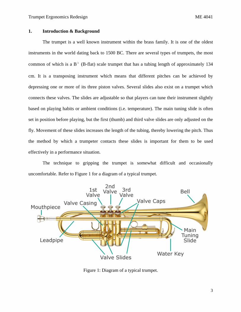
The technique to gripping the trumpet is somewhat difficult and occasionally
uncomfortable. Refer to Figure 1 for a diagram of a typical trumpet.
Figure 1: Diagram of a typical trumpet.
Trumpet Ergonomics Redesign ME 4041
4
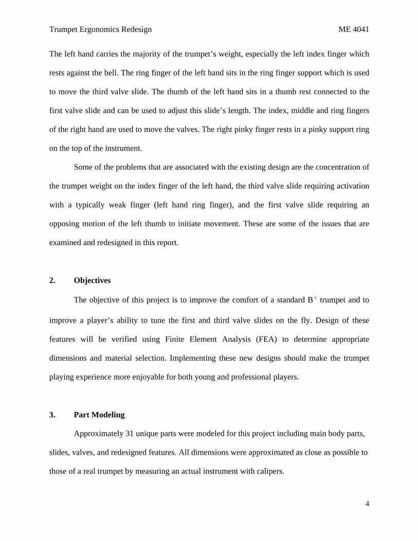
The left hand carries the majority of the trumpet’s weight, especially the left index finger which
rests against the bell. The ring finger of the left hand sits in the ring finger support which is used
to move the third valve slide. The thumb of the left hand sits in a thumb rest connected to the
first valve slide and can be used to adjust this slide’s length. The index, middle and ring fingers
of the right hand are used to move the valves. The right pinky finger rests in a pinky support ring
on the top of the instrument.
Some of the problems that are associated with the existing design are the concentration of
the trumpet weight on the index finger of the left hand, the third valve slide requiring activation
with a typically weak finger (left hand ring finger), and the first valve slide requiring an
opposing motion of the left thumb to initiate movement. These are some of the issues that are
examined and redesigned in this report.
2. Objectives
The objective of this project is to improve the comfort of a standard B♭ trumpet and to
improve a player’s ability to tune the first and third valve slides on the fly. Design of these
features will be verified using Finite Element Analysis (FEA) to determine appropriate
dimensions and material selection. Implementing these new designs should make the trumpet
playing experience more enjoyable for both young and professional players.
3. Part Modeling
Approximately 31 unique parts were modeled for this project including main body parts,
slides, valves, and redesigned features. All dimensions were approximated as close as possible to
those of a real trumpet by measuring an actual instrument with calipers.
Trumpet Ergonomics Redesign ME 4041
5
3.1. Body Parts
The trumpet body parts consist of the bell, valve housing, mouthpiece, mouthpiece tube,
and various structural and gripping supports. While many of the geometries are not difficult to
model, accurate dimensioning was critical for assembly of the many parts later in the project.
Modeling of these parts is discussed below.
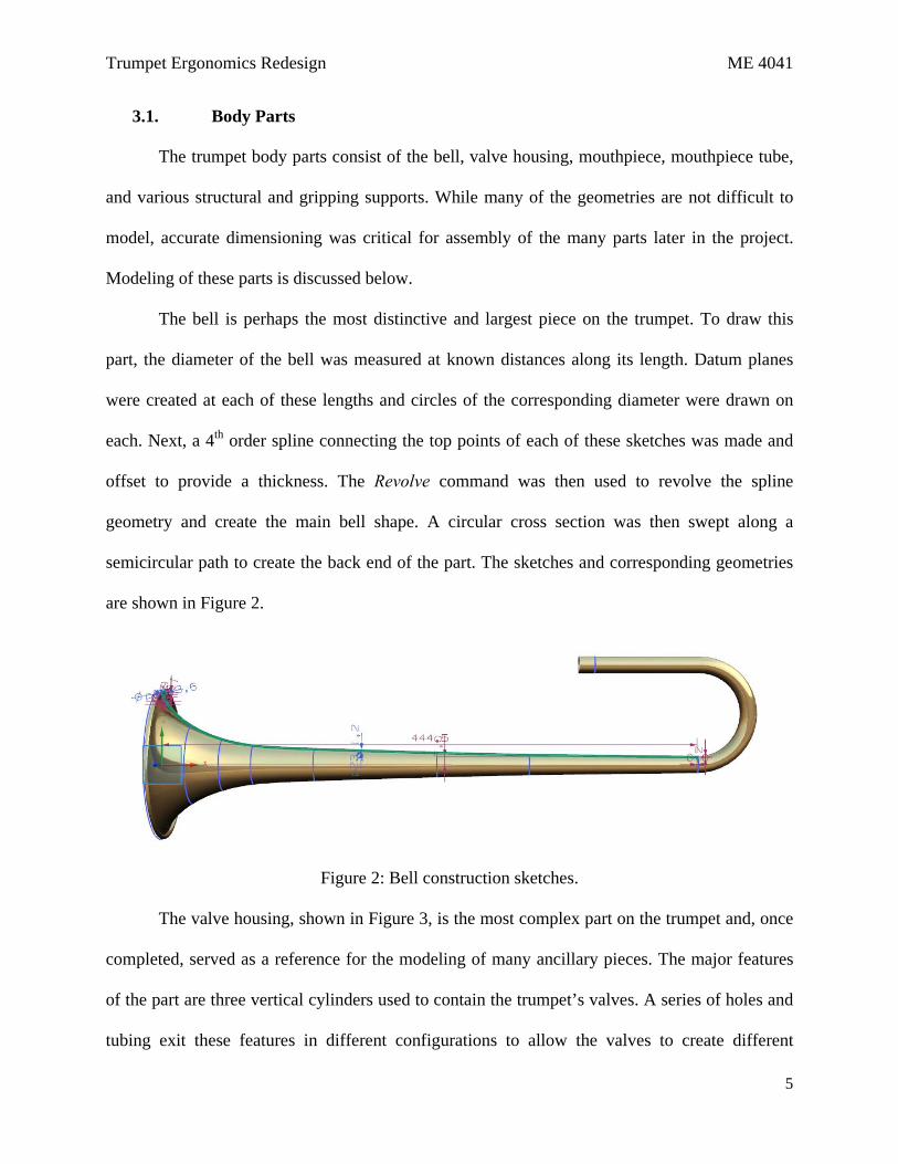
The bell is perhaps the most distinctive and largest piece on the trumpet. To draw this
part, the diameter of the bell was measured at known distances along its length. Datum planes
were created at each of these lengths and circles of the corresponding diameter were drawn on
each. Next, a 4th order spline connecting the top points of each of these sketches was made and
offset to provide a thickness. The Revolve command was then used to revolve the spline
geometry and create the main bell shape. A circular cross section was then swept along a
semicircular path to create the back end of the part. The sketches and corresponding geometries
are shown in Figure 2.
Figure 2: Bell construction sketches.
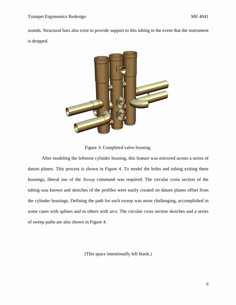
The valve housing, shown in Figure 3, is the most complex part on the trumpet and, once
completed, served as a reference for the modeling of many ancillary pieces. The major features
of the part are three vertical cylinders used to contain the trumpet’s valves. A series of holes and
tubing exit these features in different configurations to allow the valves to create different
Trumpet Ergonomics Redesign ME 4041
6
sounds. Structural bars also exist to provide support to this tubing in the event that the instrument
is dropped.
Figure 3: Completed valve housing.
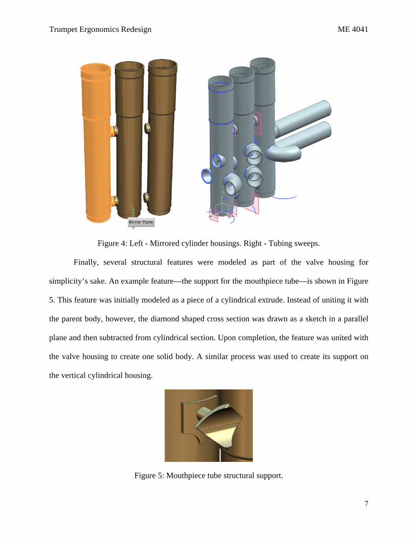
After modeling the leftmost cylinder housing, this feature was mirrored across a series of
datum planes. This process is shown in Figure 4. To model the holes and tubing exiting these
housings, liberal use of the Sweep command was required. The circular cross section of the
tubing was known and sketches of the profiles were easily created on datum planes offset from
the cylinder housings. Defining the path for each sweep was more challenging, accomplished in
some cases with splines and in others with arcs. The circular cross section sketches and a series
of sweep paths are also shown in Figure 4.
(This space intentionally left blank.)
Trumpet Ergonomics Redesign ME 4041
7
Figure 4: Left - Mirrored cylinder housings. Right - Tubing sweeps.
Finally, several structural features were modeled as part of the valve housing for
simplicity’s sake. An example feature—the support for the mouthpiece tube—is shown in Figure
5. This feature was initially modeled as a piece of a cylindrical extrude. Instead of uniting it with
the parent body, however, the diamond shaped cross section was drawn as a sketch in a parallel
plane and then subtracted from cylindrical section. Upon completion, the feature was united with
the valve housing to create one solid body. A similar process was used to create its support on
the vertical cylindrical housing.
Figure 5: Mouthpiece tube structural support.
Trumpet Ergonomics Redesign ME 4041
8
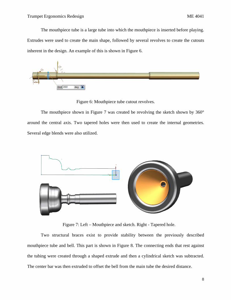
The mouthpiece tube is a large tube into which the mouthpiece is inserted before playing.
Extrudes were used to create the main shape, followed by several revolves to create the cutouts
inherent in the design. An example of this is shown in Figure 6.
Figure 6: Mouthpiece tube cutout revolves.
The mouthpiece shown in Figure 7 was created be revolving the sketch shown by 360°
around the central axis. Two tapered holes were then used to create the internal geometries.
Several edge blends were also utilized.
Figure 7: Left – Mouthpiece and sketch. Right - Tapered hole.
Two structural braces exist to provide stability between the previously described
mouthpiece tube and bell. This part is shown in Figure 8. The connecting ends that rest against
the tubing were created through a shaped extrude and then a cylindrical sketch was subtracted.
The center bar was then extruded to offset the bell from the main tube the desired distance.

Trumpet Ergonomics Redesign ME 4041
9
Figure 8: Left - Structural brace. Right – Extrude and cylindrical subtraction.
Three different finger rests for the pinky, ring finger, and thumb were also created and
are shown in Figure 9. The section of the pinky support that rests on the mouthpiece tube was
created by revolving a sketch by 20° around a reference sketch and then mirroring this piece. The
finger support was created from a sweep along a curve composed of a circular segment and an
arc. Multiple edge blends were also used.
Figure 9: Pinky, ring, and thumb finger rests, ring finger support screw.
The ring finger and thumb supports were first designed like the features found on a current
trumpet. However, these features were also redesigned as part of this project. For a discussion of
the redesign, please refer to Section 3.4. The ring finger rest was composed from a simple
extrude and multiple edge blends. The thumb rest was a little more complex requiring extrudes
and subtractions for the base support, and three studio surfaces for the section that touches the
thumb. Finally, the screw that secures the ring finger support to the 3rd valve slide was created
from an extrusion while the Instance Feature command was used to model the grip around the
head. The Thread tool was also used to create threads.
Trumpet Ergonomics Redesign ME 4041
10
3.2. Slides
Four slides were also designed to connect the various tubes projecting from the valve
housing. The main body of each of these was created by extruding and sweeping cylindrical
cross sections or using the Tube command by specifying inner and outer diameters and a curve to
sweep along. Two of these slides, however, contained knobs used to aid in their removal. The
other two contained additional support features and water valves, commonly known as “spit
valves” which added complexity.
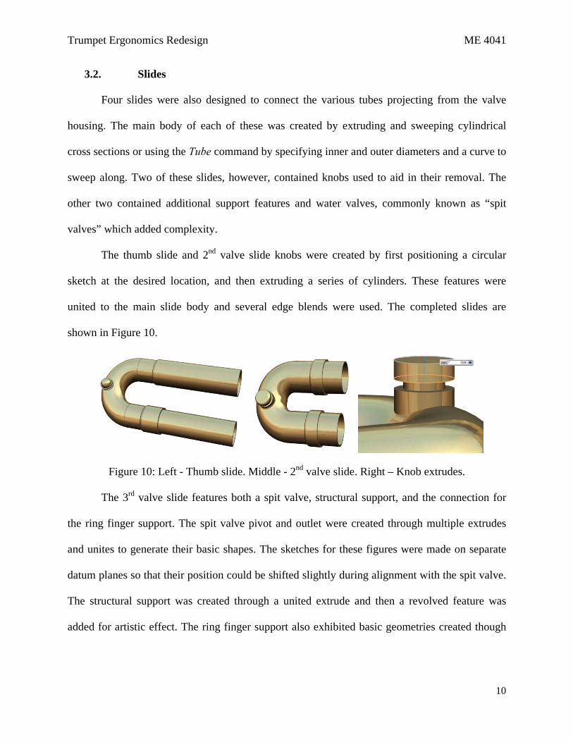
The thumb slide and 2nd valve slide knobs were created by first positioning a circular
sketch at the desired location, and then extruding a series of cylinders. These features were
united to the main slide body and several edge blends were used. The completed slides are
shown in Figure 10.
Figure 10: Left - Thumb slide. Middle - 2nd valve slide. Right – Knob extrudes.
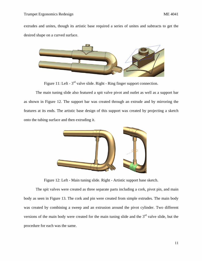
The 3rd valve slide features both a spit valve, structural support, and the connection for
the ring finger support. The spit valve pivot and outlet were created through multiple extrudes
and unites to generate their basic shapes. The sketches for these figures were made on separate
datum planes so that their position could be shifted slightly during alignment with the spit valve.
The structural support was created through a united extrude and then a revolved feature was
added for artistic effect. The ring finger support also exhibited basic geometries created though
Trumpet Ergonomics Redesign ME 4041
11
extrudes and unites, though its artistic base required a series of unites and subtracts to get the
desired shape on a curved surface.
Figure 11: Left - 3rd valve slide. Right - Ring finger support connection.
The main tuning slide also featured a spit valve pivot and outlet as well as a support bar
as shown in Figure 12. The support bar was created through an extrude and by mirroring the
features at its ends. The artistic base design of this support was created by projecting a sketch
onto the tubing surface and then extruding it.
Figure 12: Left - Main tuning slide. Right - Artistic support base sketch.
The spit valves were created as three separate parts including a cork, pivot pin, and main
body as seen in Figure 13. The cork and pin were created from simple extrudes. The main body
was created by combining a sweep and an extrusion around the pivot cylinder. Two different
versions of the main body were created for the main tuning slide and the 3rd valve slide, but the
procedure for each was the same.

Trumpet Ergonomics Redesign ME 4041
12
Figure 13: Spit valve parts and assembly.
3.3. Valves
There are three unique valves on a trumpet which are composed of a top and bottom cap,
pearl, pearl housing, felt washer, and spring base. The top and bottom cap were created by
extruding cylinders and cutouts of the desired geometry. The notches along the edges used for
gripping were created by extruding a cutout, and then using the Instance Feature command to
pattern the cutout in a circular shape. Threads were also added to the cylindrical faces that screw
onto the main housing. These two parts are pictured in Figure 14.
Figure 14: Left - Top cap. Right - Bottom cap.
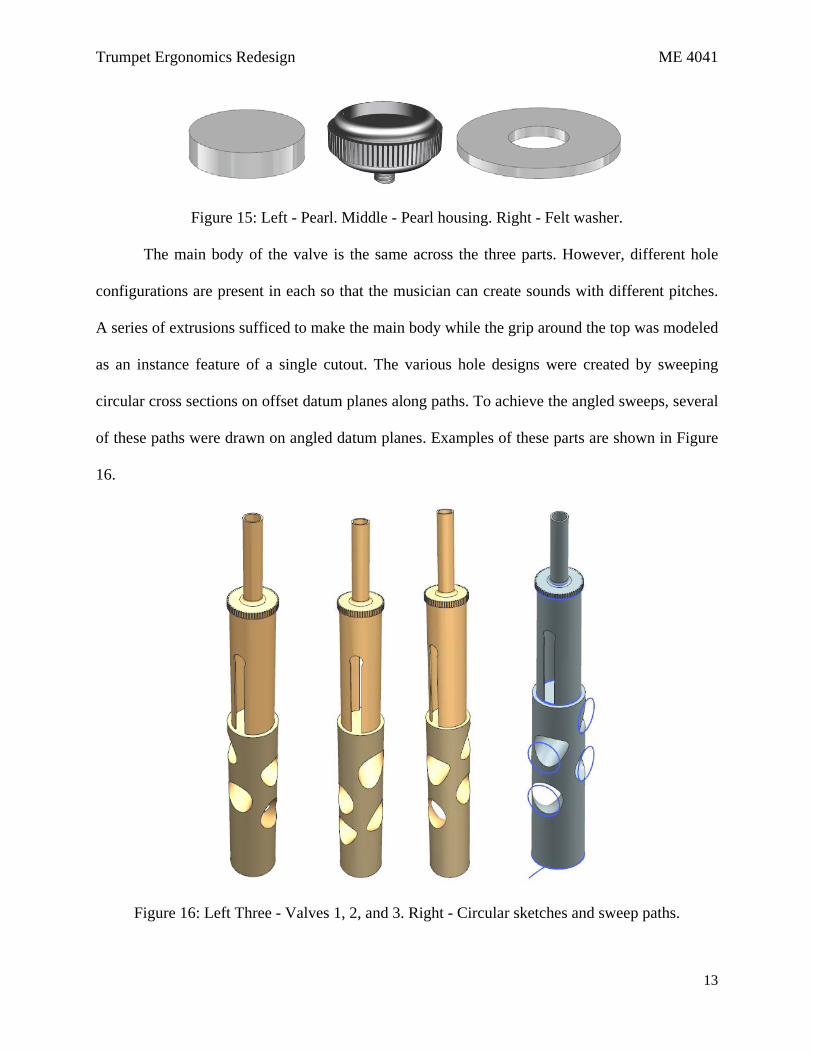
The pearl and pearl housing were also extruded and the Instance Feature command was again
used to create the grip around the top edge of the housing. Threads were added to the cylinder on
the housing that screws into the main valve. Additionally, the felt washer that softens motion of
the valve was modeled as an extrusion. These features are shown in Figure 15.
Cork Pivot Pin
Main Body
Trumpet Ergonomics Redesign ME 4041
13
Figure 15: Left - Pearl. Middle - Pearl housing. Right - Felt washer.
The main body of the valve is the same across the three parts. However, different hole
configurations are present in each so that the musician can create sounds with different pitches.
A series of extrusions sufficed to make the main body while the grip around the top was modeled
as an instance feature of a single cutout. The various hole designs were created by sweeping
circular cross sections on offset datum planes along paths. To achieve the angled sweeps, several
of these paths were drawn on angled datum planes. Examples of these parts are shown in Figure
16.
Figure 16: Left Three - Valves 1, 2, and 3. Right - Circular sketches and sweep paths.
Trumpet Ergonomics Redesign ME 4041
14
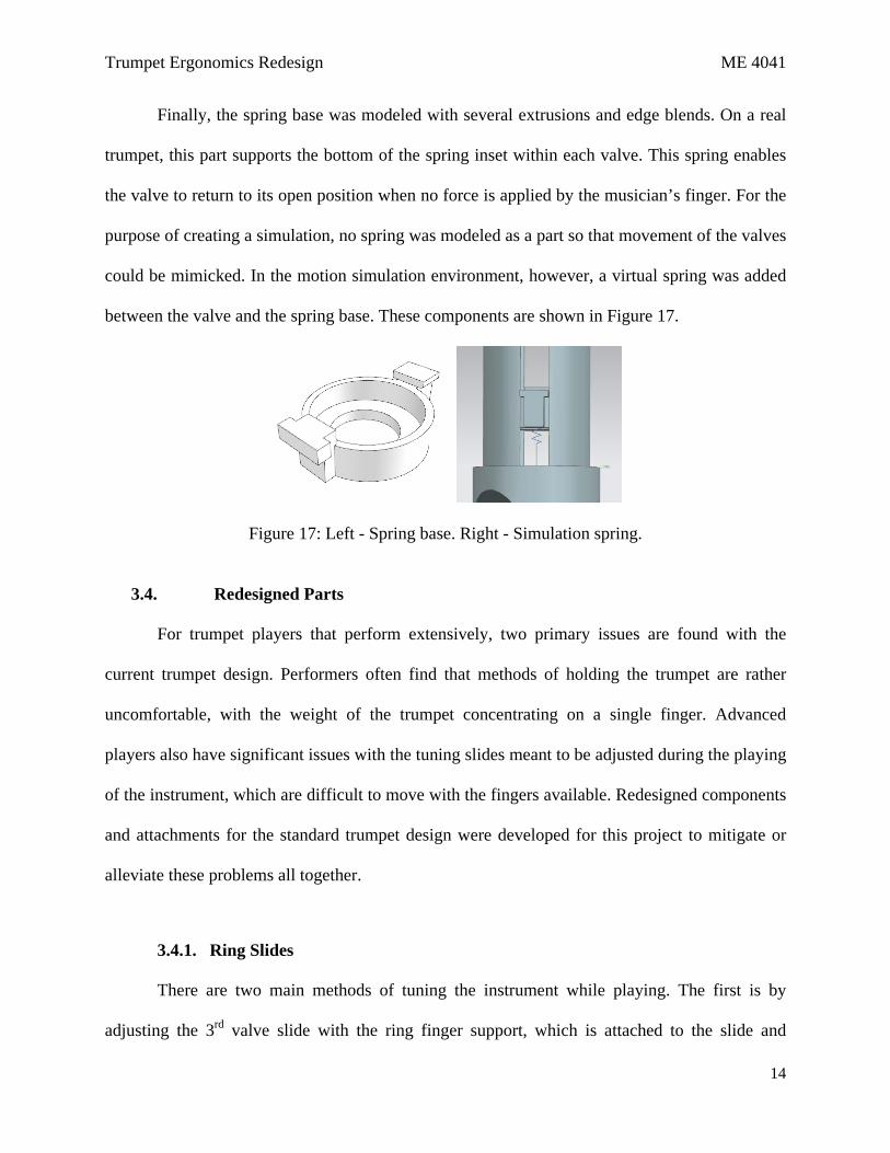
Finally, the spring base was modeled with several extrusions and edge blends. On a real
trumpet, this part supports the bottom of the spring inset within each valve. This spring enables
the valve to return to its open position when no force is applied by the musician’s finger. For the
purpose of creating a simulation, no spring was modeled as a part so that movement of the valves
could be mimicked. In the motion simulation environment, however, a virtual spring was added
between the valve and the spring base. These components are shown in Figure 17.
Figure 17: Left - Spring base. Right - Simulation spring.
3.4. Redesigned Parts
For trumpet players that perform extensively, two primary issues are found with the
current trumpet design. Performers often find that methods of holding the trumpet are rather
uncomfortable, with the weight of the trumpet concentrating on a single finger. Advanced
players also have significant issues with the tuning slides meant to be adjusted during the playing
of the instrument, which are difficult to move with the fingers available. Redesigned components
and attachments for the standard trumpet design were developed for this project to mitigate or
alleviate these problems all together.
3.4.1. Ring Slides
There are two main methods of tuning the instrument while playing. The first is by
adjusting the 3rd valve slide with the ring finger support, which is attached to the slide and
Trumpet Ergonomics Redesign ME 4041
15
protrudes back to be adjusted by the ring finger of the left hand. The second method is to adjust
the back or thumb slide using the thumb of the left hand in a crevice directly attached to the
slide. The ring support redesign addresses the first method of tuning on the 3rd valve or forward
slide.
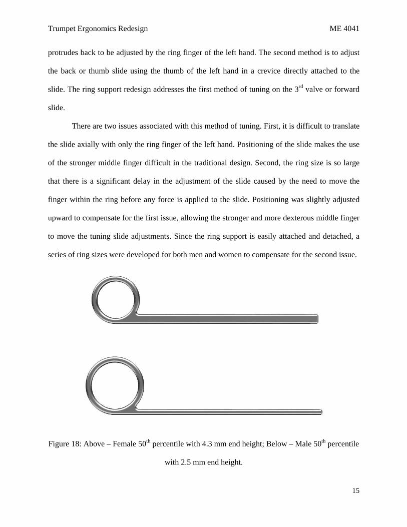
There are two issues associated with this method of tuning. First, it is difficult to translate
the slide axially with only the ring finger of the left hand. Positioning of the slide makes the use
of the stronger middle finger difficult in the traditional design. Second, the ring size is so large
that there is a significant delay in the adjustment of the slide caused by the need to move the
finger within the ring before any force is applied to the slide. Positioning was slightly adjusted
upward to compensate for the first issue, allowing the stronger and more dexterous middle finger
to move the tuning slide adjustments. Since the ring support is easily attached and detached, a
series of ring sizes were developed for both men and women to compensate for the second issue.
Figure 18: Above – Female 50th percentile with 4.3 mm end height; Below – Male 50th percentile
with 2.5 mm end height.
Trumpet Ergonomics Redesign ME 4041
16
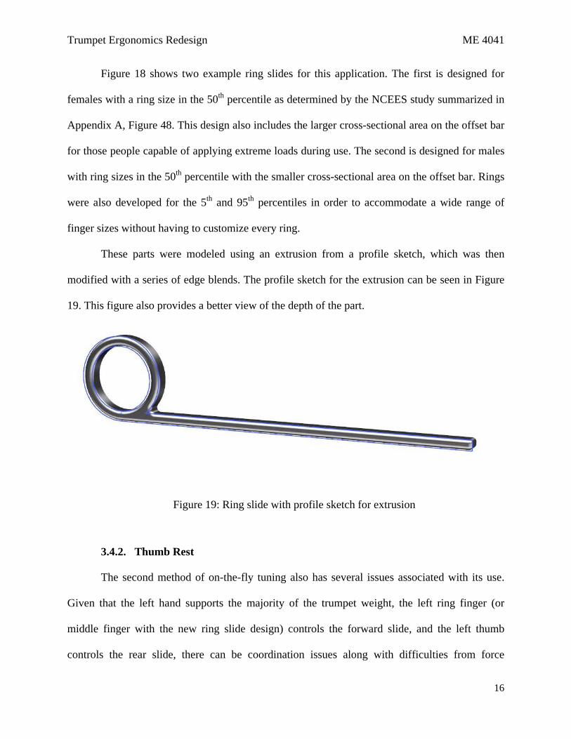
Figure 18 shows two example ring slides for this application. The first is designed for
females with a ring size in the 50th percentile as determined by the NCEES study summarized in
Appendix A, Figure 48. This design also includes the larger cross-sectional area on the offset bar
for those people capable of applying extreme loads during use. The second is designed for males
with ring sizes in the 50th percentile with the smaller cross-sectional area on the offset bar. Rings
were also developed for the 5th and 95th percentiles in order to accommodate a wide range of
finger sizes without having to customize every ring.
These parts were modeled using an extrusion from a profile sketch, which was then
modified with a series of edge blends. The profile sketch for the extrusion can be seen in Figure
19. This figure also provides a better view of the depth of the part.
Figure 19: Ring slide with profile sketch for extrusion
3.4.2. Thumb Rest
The second method of on-the-fly tuning also has several issues associated with its use.
Given that the left hand supports the majority of the trumpet weight, the left ring finger (or
middle finger with the new ring slide design) controls the forward slide, and the left thumb
controls the rear slide, there can be coordination issues along with difficulties from force

Trumpet Ergonomics Redesign ME 4041
17
resolutions. That is to say that the application of force to move the front slide makes it difficult to
simultaneously adjust the rear slide. The curved structure designed to allow the thumb to move
the rear slide is too wide in a similar fashion to the forward slide rings.
To resolve these issues, the duty of movement of the rear slide was reallocated to the right
thumb, which normally simply rests beside the trumpet. The ring was also made smaller and
more ergonomic to avoid any delay from finger movement associated with the adjustment of the
slide. In order to allow the right thumb to access the slide, the rest was moved approximately 20
mm above the slide using a set of three legs attached to the slide. The top two legs prevent
significant forces from bending the rest axially along the trumpet, while the third prevents lateral
movement. The rear leg is extended back in order to translate as much of the force applied to the
rest in the direction of movement. Figure 20 shows how this thumb rest would appear.
Figure 20: Thumb rest rendering.
In order to model this component, a set of circular extrusions were created to mimic the
existence of the slide parts. A reference plane was created 20 mm above the higher of the two
extrusions, which is where the thumb rest is mounted on the legs. A 5 control point spline was
Trumpet Ergonomics Redesign ME 4041
18
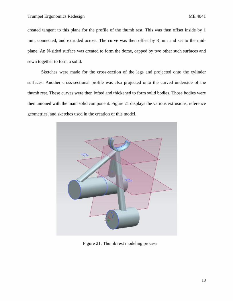
created tangent to this plane for the profile of the thumb rest. This was then offset inside by 1
mm, connected, and extruded across. The curve was then offset by 3 mm and set to the mid-
plane. An N-sided surface was created to form the dome, capped by two other such surfaces and
sewn together to form a solid.
Sketches were made for the cross-section of the legs and projected onto the cylinder
surfaces. Another cross-sectional profile was also projected onto the curved underside of the
thumb rest. These curves were then lofted and thickened to form solid bodies. Those bodies were
then unioned with the main solid component. Figure 21 displays the various extrusions, reference
geometries, and sketches used in the creation of this model.
Figure 21: Thumb rest modeling process

Trumpet Ergonomics Redesign ME 4041
19
3.4.3. Hand Support
The issue of comfort while playing is addressed through the addition of a hand support
structure that can be easily added to any existing trumpet design. This solves the discomfort in
two ways. First, it provides a soft material that allows the palm of the left hand to rest in a more
relaxed position rather than against the side of the trumpet. This separation space reduces the
discomfort felt when the left hand palm is forced against the side of the trumpet in order to
stabilize it while being played. Second, a grooved finger slide distributes the weight of the
trumpet along the entirety of the top of the finger and part of the hand. Usually, the majority of
the weight of the trumpet is held by the end of the left index finger. However, this hand support
distributes that weight over a larger area, reducing the stresses felt by that finger and thus the
likelihood of developing medical conditions associated with constant stresses on particular body
parts.
Figure 22: Hand support front view
Trumpet Ergonomics Redesign ME 4041
20
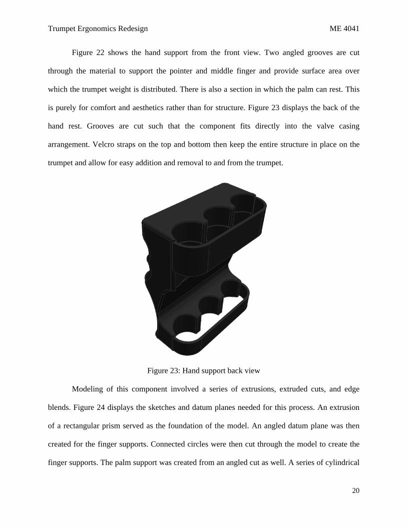
Figure 22 shows the hand support from the front view. Two angled grooves are cut
through the material to support the pointer and middle finger and provide surface area over
which the trumpet weight is distributed. There is also a section in which the palm can rest. This
is purely for comfort and aesthetics rather than for structure. Figure 23 displays the back of the
hand rest. Grooves are cut such that the component fits directly into the valve casing
arrangement. Velcro straps on the top and bottom then keep the entire structure in place on the
trumpet and allow for easy addition and removal to and from the trumpet.
Figure 23: Hand support back view
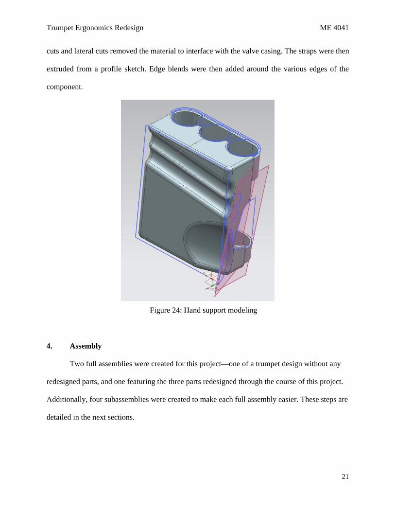
Modeling of this component involved a series of extrusions, extruded cuts, and edge
blends. Figure 24 displays the sketches and datum planes needed for this process. An extrusion
of a rectangular prism served as the foundation of the model. An angled datum plane was then
created for the finger supports. Connected circles were then cut through the model to create the
finger supports. The palm support was created from an angled cut as well. A series of cylindrical
Trumpet Ergonomics Redesign ME 4041
21
cuts and lateral cuts removed the material to interface with the valve casing. The straps were then
extruded from a profile sketch. Edge blends were then added around the various edges of the
component.
Figure 24: Hand support modeling
4. Assembly
Two full assemblies were created for this project—one of a trumpet design without any
redesigned parts, and one featuring the three parts redesigned through the course of this project.
Additionally, four subassemblies were created to make each full assembly easier. These steps are
detailed in the next sections.
Trumpet Ergonomics Redesign ME 4041
22
4.1. Subassemblies
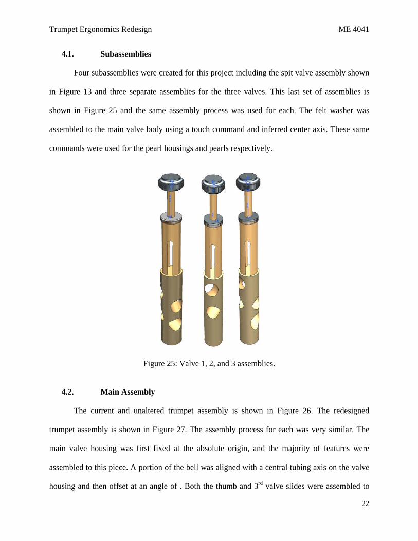
Four subassemblies were created for this project including the spit valve assembly shown
in Figure 13 and three separate assemblies for the three valves. This last set of assemblies is
shown in Figure 25 and the same assembly process was used for each. The felt washer was
assembled to the main valve body using a touch command and inferred center axis. These same
commands were used for the pearl housings and pearls respectively.
Figure 25: Valve 1, 2, and 3 assemblies.
4.2. Main Assembly
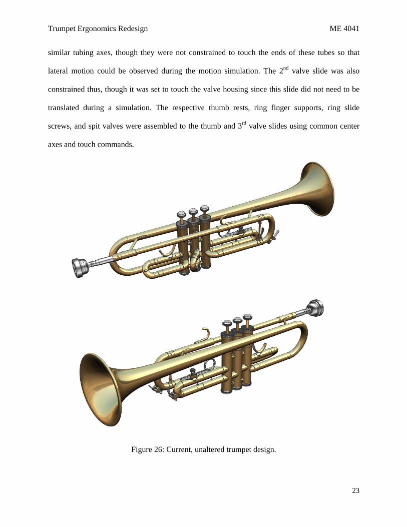
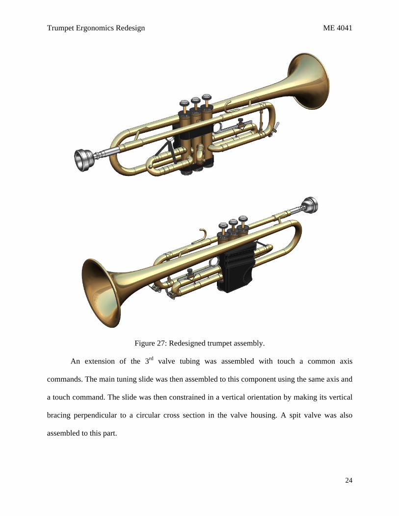
The current and unaltered trumpet assembly is shown in Figure 26. The redesigned
trumpet assembly is shown in Figure 27. The assembly process for each was very similar. The
main valve housing was first fixed at the absolute origin, and the majority of features were
assembled to this piece. A portion of the bell was aligned with a central tubing axis on the valve
housing and then offset at an angle of . Both the thumb and 3rd valve slides were assembled to
Trumpet Ergonomics Redesign ME 4041
23
similar tubing axes, though they were not constrained to touch the ends of these tubes so that
lateral motion could be observed during the motion simulation. The 2nd valve slide was also
constrained thus, though it was set to touch the valve housing since this slide did not need to be
translated during a simulation. The respective thumb rests, ring finger supports, ring slide
screws, and spit valves were assembled to the thumb and 3rd valve slides using common center
axes and touch commands.
Figure 26: Current, unaltered trumpet design.
Trumpet Ergonomics Redesign ME 4041
24
Figure 27: Redesigned trumpet assembly.
An extension of the 3rd valve tubing was assembled with touch a common axis
commands. The main tuning slide was then assembled to this component using the same axis and
a touch command. The slide was then constrained in a vertical orientation by making its vertical
bracing perpendicular to a circular cross section in the valve housing. A spit valve was also
assembled to this part.
Trumpet Ergonomics Redesign ME 4041
25
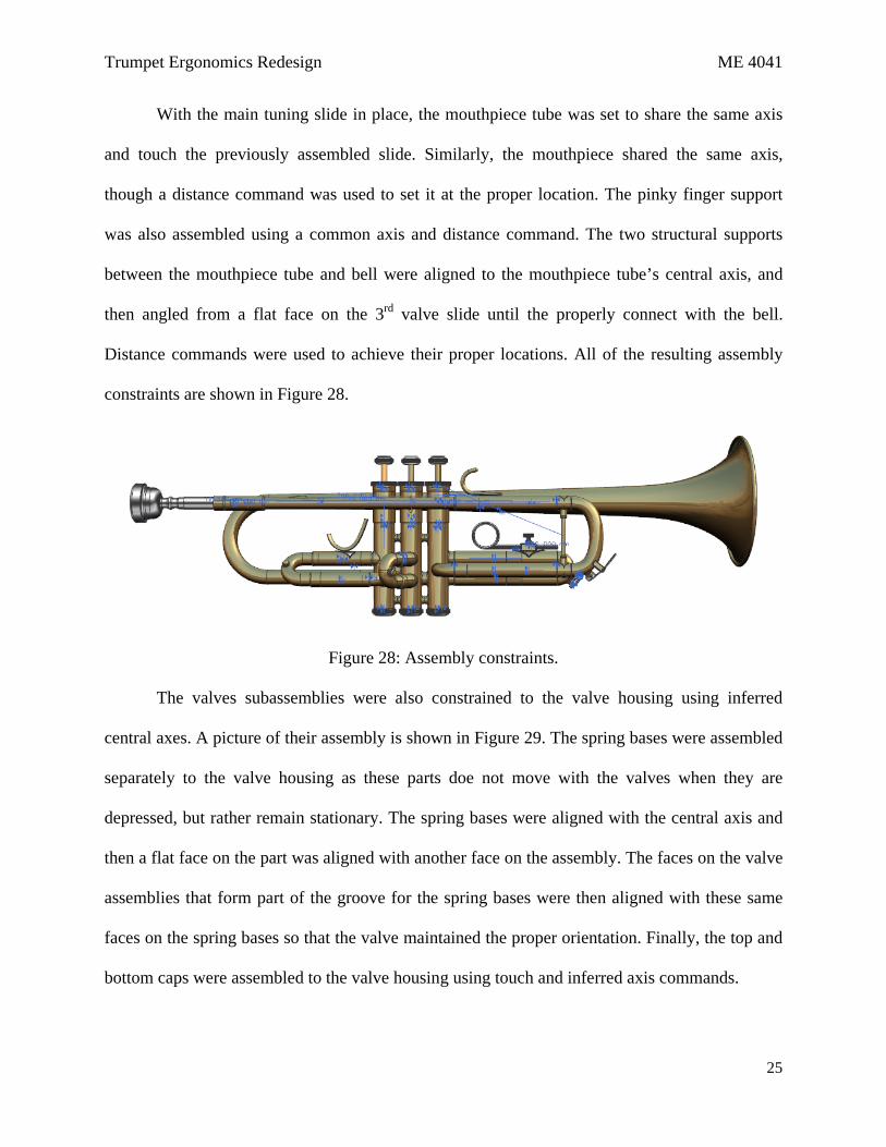
With the main tuning slide in place, the mouthpiece tube was set to share the same axis
and touch the previously assembled slide. Similarly, the mouthpiece shared the same axis,
though a distance command was used to set it at the proper location. The pinky finger support
was also assembled using a common axis and distance command. The two structural supports
between the mouthpiece tube and bell were aligned to the mouthpiece tube’s central axis, and
then angled from a flat face on the 3rd valve slide until the properly connect with the bell.
Distance commands were used to achieve their proper locations. All of the resulting assembly
constraints are shown in Figure 28.
Figure 28: Assembly constraints.
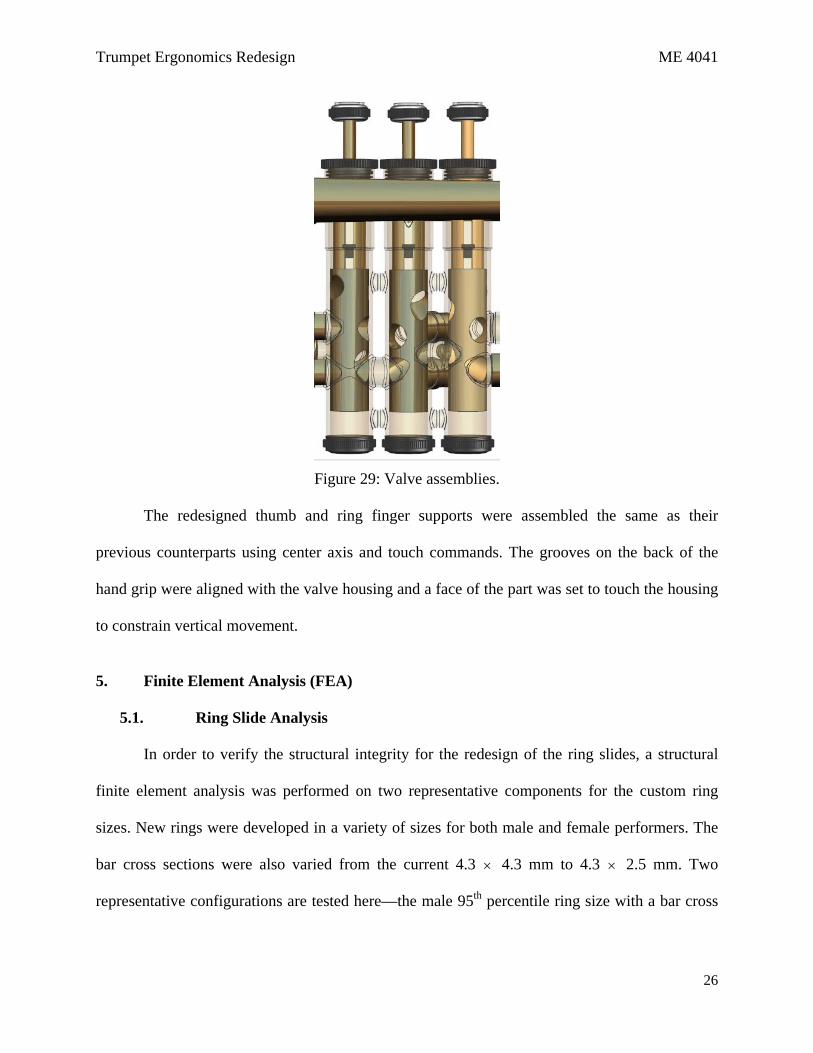
The valves subassemblies were also constrained to the valve housing using inferred
central axes. A picture of their assembly is shown in Figure 29. The spring bases were assembled
separately to the valve housing as these parts doe not move with the valves when they are
depressed, but rather remain stationary. The spring bases were aligned with the central axis and
then a flat face on the part was aligned with another face on the assembly. The faces on the valve
assemblies that form part of the groove for the spring bases were then aligned with these same
faces on the spring bases so that the valve maintained the proper orientation. Finally, the top and
bottom caps were assembled to the valve housing using touch and inferred axis commands.
Trumpet Ergonomics Redesign ME 4041
26
Figure 29: Valve assemblies.
The redesigned thumb and ring finger supports were assembled the same as their
previous counterparts using center axis and touch commands. The grooves on the back of the
hand grip were aligned with the valve housing and a face of the part was set to touch the housing
to constrain vertical movement.
5. Finite Element Analysis (FEA)
5.1. Ring Slide Analysis
In order to verify the structural integrity for the redesign of the ring slides, a structural
finite element analysis was performed on two representative components for the custom ring
sizes. New rings were developed in a variety of sizes for both male and female performers. The
bar cross sections were also varied from the current 4.3 × 4.3 mm to 4.3 × 2.5 mm. Two
representative configurations are tested here—the male 95th percentile ring size with a bar cross
Trumpet Ergonomics Redesign ME 4041
27
section of 4.3 × 4.3 mm and the female 50th percentile ring size with a bar cross section of 4.3 ×
2.5 mm.
The most extreme load cases were analyzed for both cases, where the material geometries
were such that the most deflection would occur for those cases and the load was the maximum
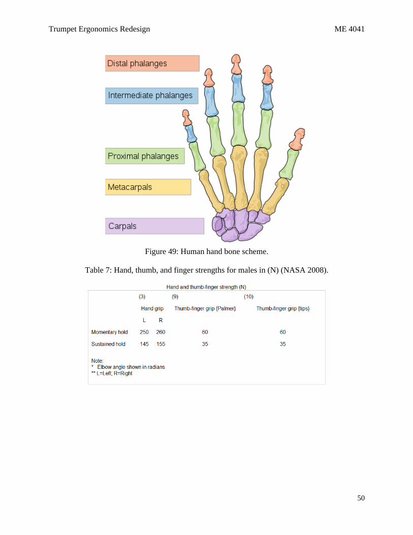
possible load for a human to apply. Loads were determined from the NASA study summarized in
Table 7 of Appendix A, where the maximum force for a male for the thumb-to-finger grip is 60
N. The ring was said to be fixed at the very end, giving the largest moment arm possible for
multi-dimensional forces and resulting in the largest deflection. The material is assumed to be a
mild 310 stainless steel with a Young’s Modulus of approximately 200 GPa.
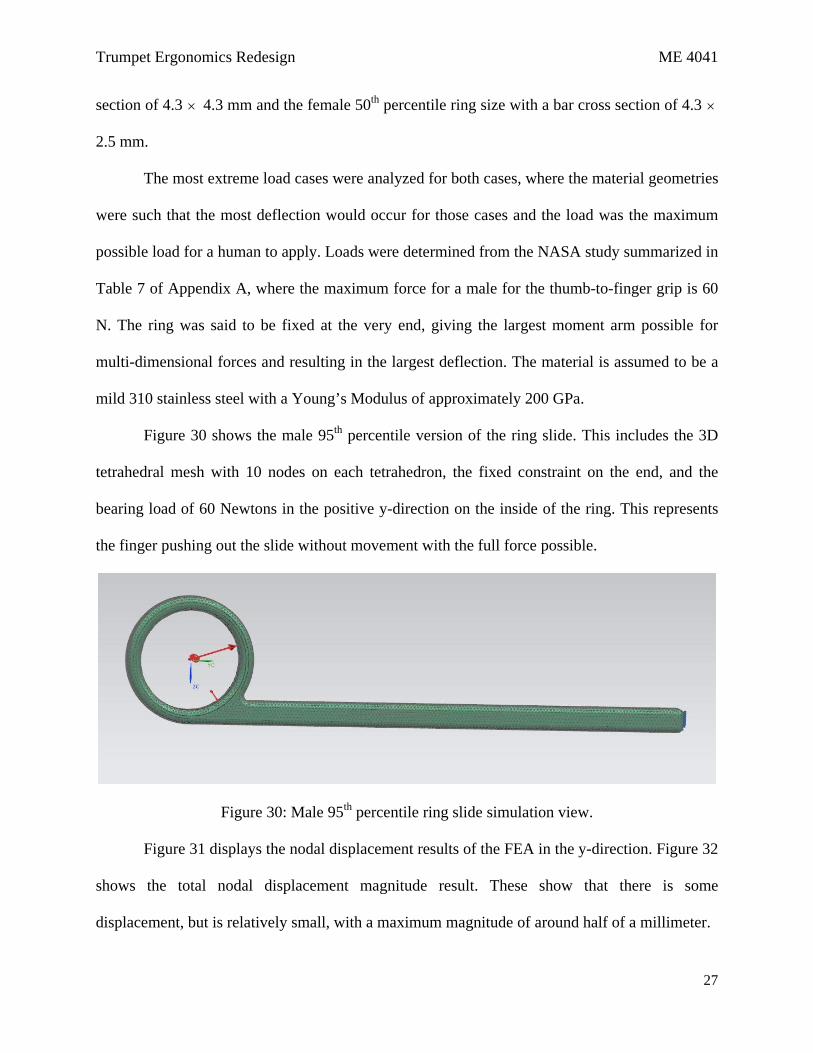
Figure 30 shows the male 95th percentile version of the ring slide. This includes the 3D
tetrahedral mesh with 10 nodes on each tetrahedron, the fixed constraint on the end, and the
bearing load of 60 Newtons in the positive y-direction on the inside of the ring. This represents
the finger pushing out the slide without movement with the full force possible.
Figure 30: Male 95th percentile ring slide simulation view.
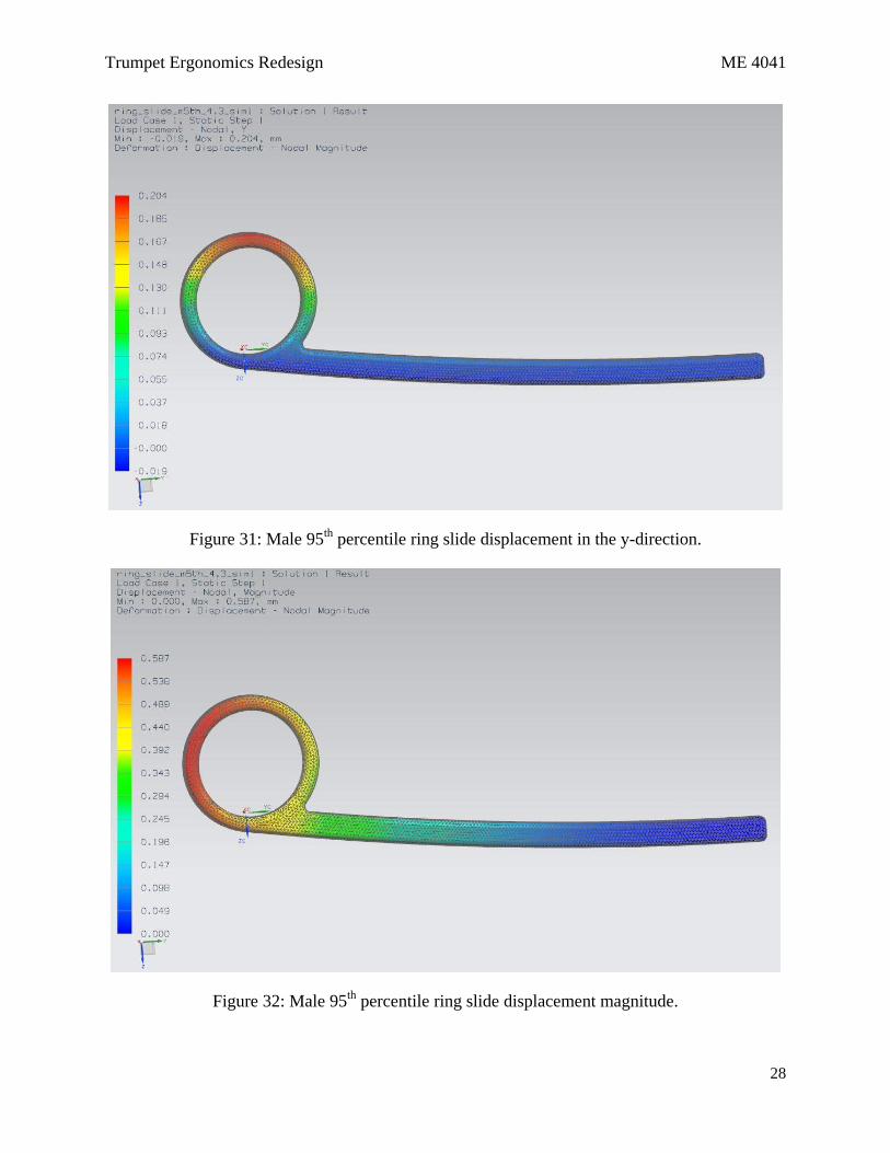
Figure 31 displays the nodal displacement results of the FEA in the y-direction. Figure 32
shows the total nodal displacement magnitude result. These show that there is some
displacement, but is relatively small, with a maximum magnitude of around half of a millimeter.
Trumpet Ergonomics Redesign ME 4041
28
Figure 31: Male 95th percentile ring slide displacement in the y-direction.
Figure 32: Male 95th percentile ring slide displacement magnitude.
Trumpet Ergonomics Redesign ME 4041
29
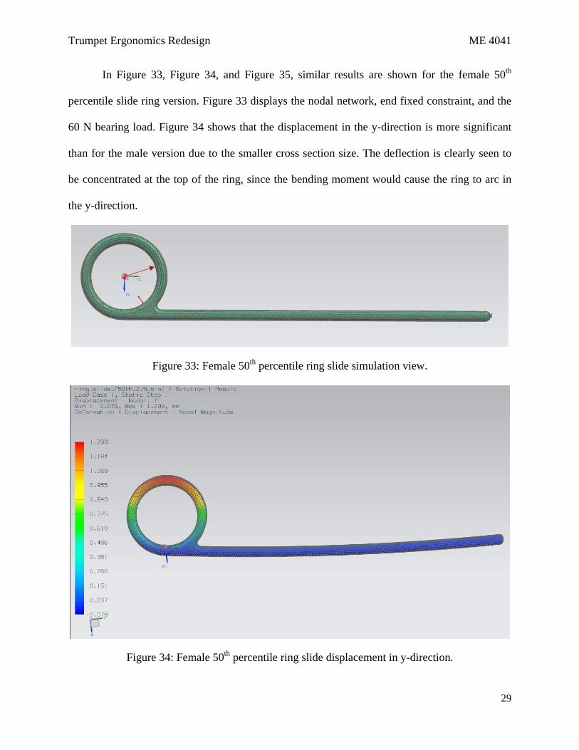
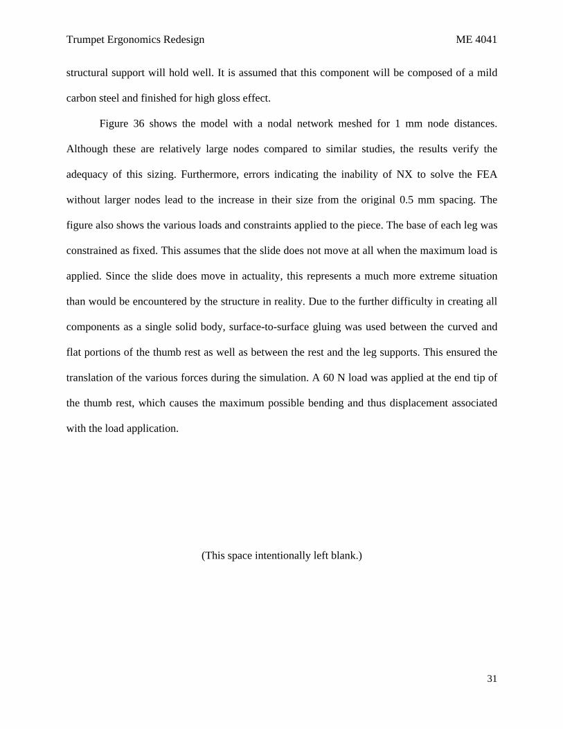
In Figure 33, Figure 34, and Figure 35, similar results are shown for the female 50th
percentile slide ring version. Figure 33 displays the nodal network, end fixed constraint, and the
60 N bearing load. Figure 34 shows that the displacement in the y-direction is more significant
than for the male version due to the smaller cross section size. The deflection is clearly seen to
be concentrated at the top of the ring, since the bending moment would cause the ring to arc in
the y-direction.
Figure 33: Female 50th percentile ring slide simulation view.
Figure 34: Female 50th percentile ring slide displacement in y-direction.

Trumpet Ergonomics Redesign ME 4041
30
Figure 35: Female 50th percentile ring slide displacement magnitude.
Figure 35 gives a maximum displacement magnitude with the smaller bar cross section of
4.371 mm. While it was hoped that redesigning the ring slide bar to include less material would
be possible, this result shows that maintaining the current bar cross section of 4.3 × 4.3 mm is
desirable to minimize displacement during worst case scenario loading. Thus a variety of ring
sizes will be offered for this trumpet redesign based on the performer’s preference, but the bar
cross section will remain the same as the current trumpet design.
5.2. Thumb Rest Analysis
In order to verify the structural integrity of the new thumb rest redesign, it must be shown
that the triple support beams provide adequate support under the maximum load that can be
applied by a human at that interface. The NASA study outlined in Table 7 of Appendix A can
again be referenced for the maximum finger tip load of 60 N in the 50th percentile of men. It
must be shown that under this instantaneous load applied to the worst possible location that the
Trumpet Ergonomics Redesign ME 4041
31
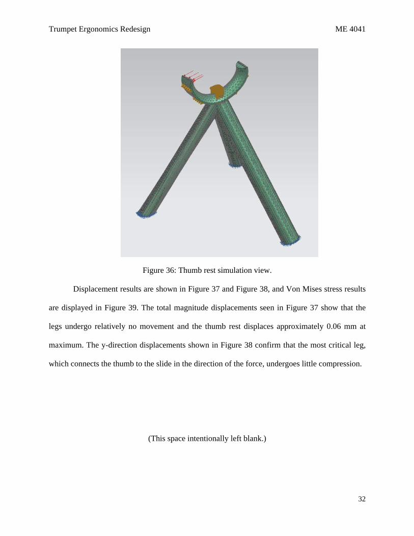
structural support will hold well. It is assumed that this component will be composed of a mild
carbon steel and finished for high gloss effect.
Figure 36 shows the model with a nodal network meshed for 1 mm node distances.
Although these are relatively large nodes compared to similar studies, the results verify the
adequacy of this sizing. Furthermore, errors indicating the inability of NX to solve the FEA
without larger nodes lead to the increase in their size from the original 0.5 mm spacing. The
figure also shows the various loads and constraints applied to the piece. The base of each leg was
constrained as fixed. This assumes that the slide does not move at all when the maximum load is
applied. Since the slide does move in actuality, this represents a much more extreme situation
than would be encountered by the structure in reality. Due to the further difficulty in creating all
components as a single solid body, surface-to-surface gluing was used between the curved and
flat portions of the thumb rest as well as between the rest and the leg supports. This ensured the
translation of the various forces during the simulation. A 60 N load was applied at the end tip of
the thumb rest, which causes the maximum possible bending and thus displacement associated
with the load application.
(This space intentionally left blank.)
Trumpet Ergonomics Redesign ME 4041
32
Figure 36: Thumb rest simulation view.
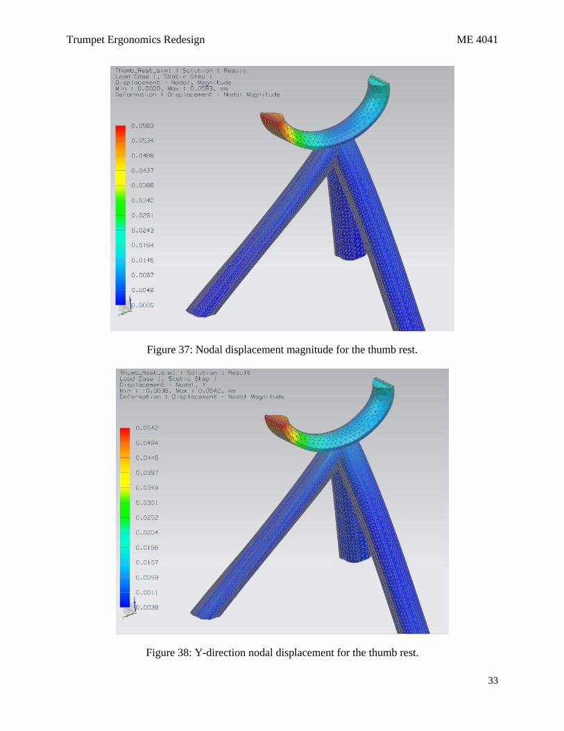
Displacement results are shown in Figure 37 and Figure 38, and Von Mises stress results
are displayed in Figure 39. The total magnitude displacements seen in Figure 37 show that the
legs undergo relatively no movement and the thumb rest displaces approximately 0.06 mm at
maximum. The y-direction displacements shown in Figure 38 confirm that the most critical leg,
which connects the thumb to the slide in the direction of the force, undergoes little compression.
(This space intentionally left blank.)
Trumpet Ergonomics Redesign ME 4041
33
Figure 37: Nodal displacement magnitude for the thumb rest.
Figure 38: Y-direction nodal displacement for the thumb rest.
Trumpet Ergonomics Redesign ME 4041
34
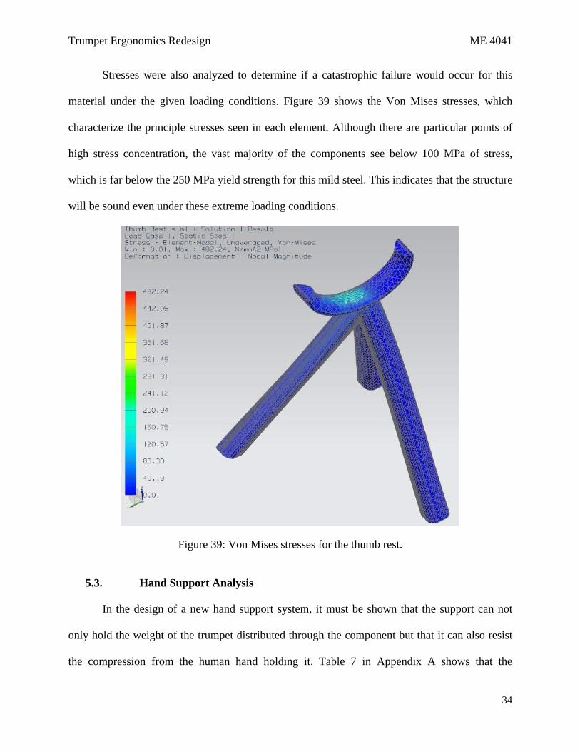
Stresses were also analyzed to determine if a catastrophic failure would occur for this
material under the given loading conditions. Figure 39 shows the Von Mises stresses, which
characterize the principle stresses seen in each element. Although there are particular points of
high stress concentration, the vast majority of the components see below 100 MPa of stress,
which is far below the 250 MPa yield strength for this mild steel. This indicates that the structure
will be sound even under these extreme loading conditions.
Figure 39: Von Mises stresses for the thumb rest.
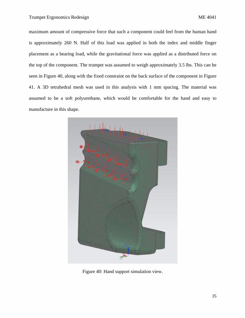
5.3. Hand Support Analysis
In the design of a new hand support system, it must be shown that the support can not
only hold the weight of the trumpet distributed through the component but that it can also resist
the compression from the human hand holding it. Table 7 in Appendix A shows that the
Trumpet Ergonomics Redesign ME 4041
35
maximum amount of compressive force that such a component could feel from the human hand
is approximately 260 N. Half of this load was applied in both the index and middle finger
placement as a bearing load, while the gravitational force was applied as a distributed force on
the top of the component. The trumpet was assumed to weigh approximately 3.5 lbs. This can be
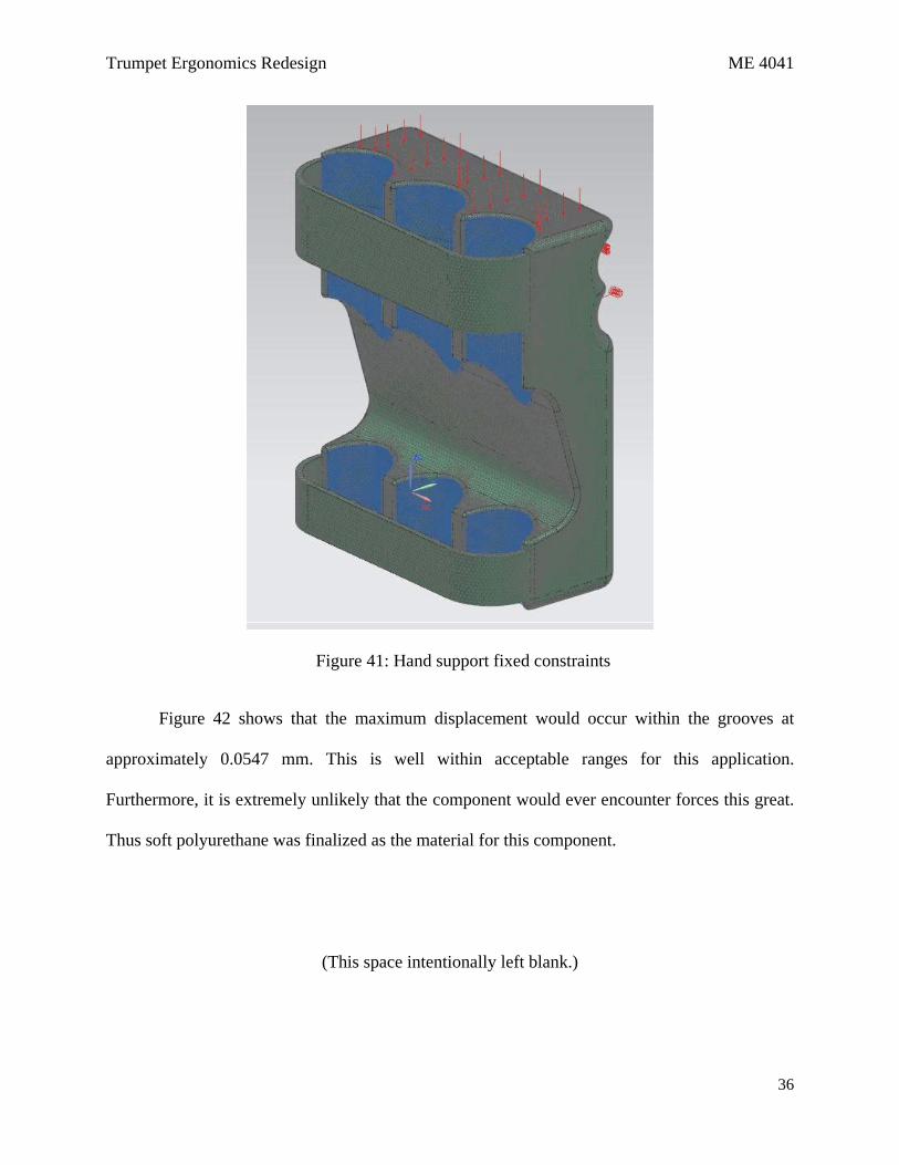
seen in Figure 40, along with the fixed constraint on the back surface of the component in Figure
41. A 3D tetrahedral mesh was used in this analysis with 1 mm spacing. The material was
assumed to be a soft polyurethane, which would be comfortable for the hand and easy to
manufacture in this shape.
Figure 40: Hand support simulation view.
Trumpet Ergonomics Redesign ME 4041
36
Figure 41: Hand support fixed constraints
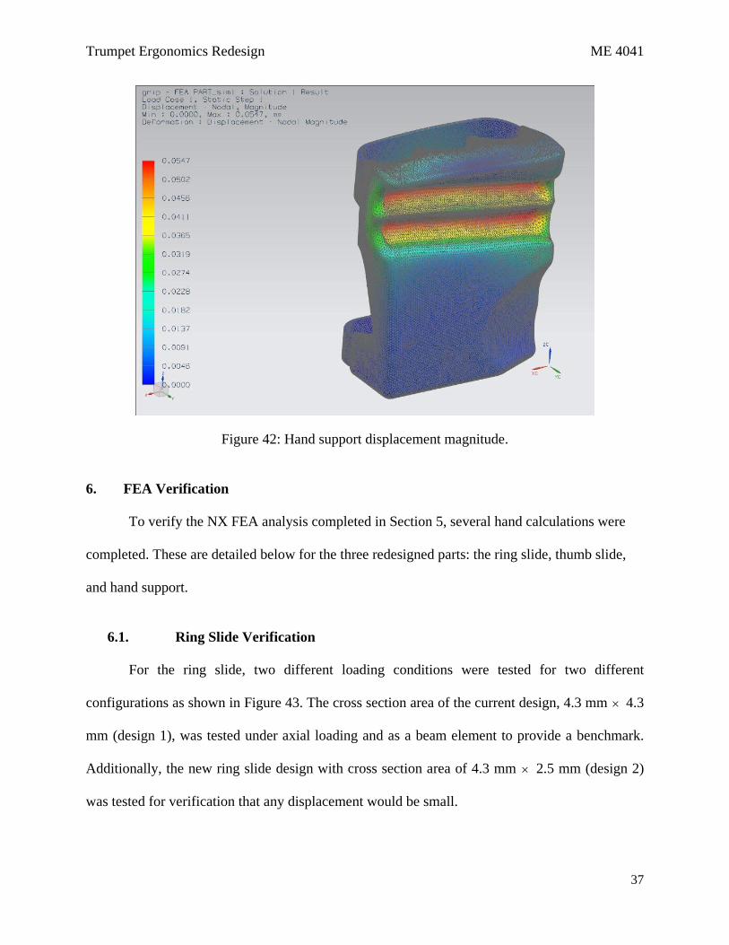
Figure 42 shows that the maximum displacement would occur within the grooves at
approximately 0.0547 mm. This is well within acceptable ranges for this application.
Furthermore, it is extremely unlikely that the component would ever encounter forces this great.
Thus soft polyurethane was finalized as the material for this component.
(This space intentionally left blank.)
Trumpet Ergonomics Redesign ME 4041
37
Figure 42: Hand support displacement magnitude.
6. FEA Verification
To verify the NX FEA analysis completed in Section 5, several hand calculations were
completed. These are detailed below for the three redesigned parts: the ring slide, thumb slide,
and hand support.
6.1. Ring Slide Verification
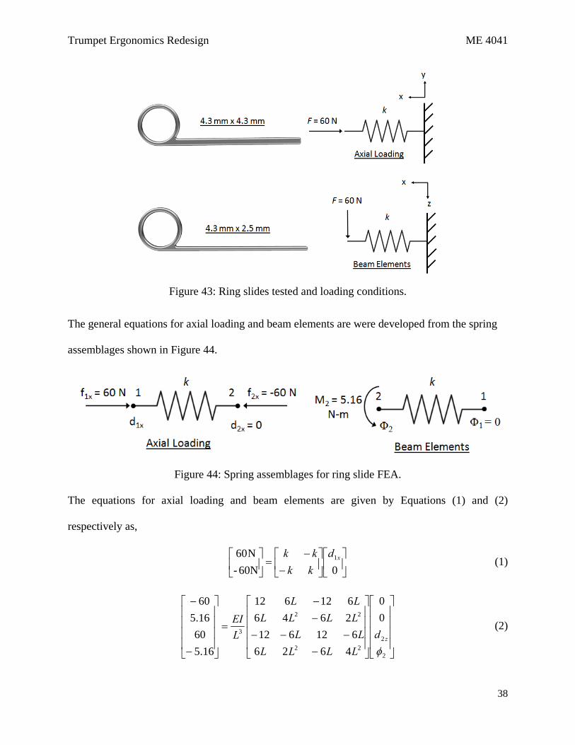
For the ring slide, two different loading conditions were tested for two different
configurations as shown in Figure 43. The cross section area of the current design, 4.3 mm × 4.3
mm (design 1), was tested under axial loading and as a beam element to provide a benchmark.
Additionally, the new ring slide design with cross section area of 4.3 mm × 2.5 mm (design 2)
was tested for verification that any displacement would be small.
Trumpet Ergonomics Redesign ME 4041
38
Figure 43: Ring slides tested and loading conditions.
The general equations for axial loading and beam elements are were developed from the spring
assemblages shown in Figure 44.
Figure 44: Spring assemblages for ring slide FEA.
The equations for axial loading and beam elements are given by Equations (1) and (2)
respectively as,
⎥⎦
⎤⎢⎣
⎡⎥⎦
⎤⎢⎣
⎡−
−=⎥
⎦
⎤⎢⎣
⎡060N-
N60 1xdkkkk
(1)
⎥⎥⎥⎥
⎦
⎤
⎢⎢⎢⎢
⎣
⎡
⎥⎥⎥⎥
⎦
⎤
⎢⎢⎢⎢
⎣
⎡
−−−−
−−
=
⎥⎥⎥⎥
⎦
⎤
⎢⎢⎢⎢
⎣
⎡
−
−
2
222
22
3
00
4626612612
2646612612
16.56016.560
φzd
LLLLLL
LLLLLL
LEI (2)
Trumpet Ergonomics Redesign ME 4041
39
Where k is the stiffness given in Equation (3), d1x is the displacement in x at node 1, L is the
length of the bar, d2z is the displacement in z at node 2, ϕ2 is the angular displacement at node 2,
E is the Young’s Modulus of steel, and I is the area moment of inertia given by Equation (4).
L
AEk = (3)
Where A is the area of the bar and,
12
3bhI = (4)
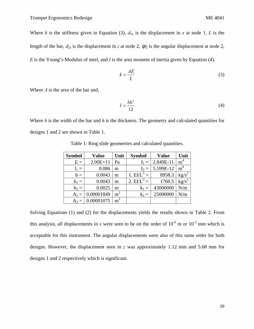
Where b is the width of the bar and h is the thickness. The geometry and calculated quantities for
designs 1 and 2 are shown in Table 1.
Table 1: Ring slide geometries and calculated quantities.
Symbol Value Unit Symbol Value Unit E = 2.00E+11 Pa I1 = 2.849E-11 m4 L = 0.086 m I2 = 5.599E-12 m4 b = 0.0043 m 1. EI/L3 = 8958.3 kg/s2
h1 = 0.0043 m 2. EI/L3 = 1760.5 kg/s2 h2 = 0.0025 m k1 = 43000000 N/m A1 = 0.00001849 m2 k2 = 25000000 N/m A2 = 0.00001075 m2
Solving Equations (1) and (2) for the displacements yields the results shown in Table 2. From
this analysis, all displacements in x were seen to be on the order of 10-6 m or 10-3 mm which is
acceptable for this instrument. The angular displacements were also of this same order for both
designs. However, the displacement seen in z was approximately 1.12 mm and 5.68 mm for
designs 1 and 2 respectively which is significant.

Trumpet Ergonomics Redesign ME 4041
40
Table 2: Results of Ring Slide FEA Verification.
Axial Loading design 1 d1x = 1.40E-06 m design 2 d1x = 2.40E-06 m
Beam Elements ϕ2 = 7.20E-07 degreesdesign 1d2z = 0.00112 m ϕ2 = 1.24E-06 degreesdesign 2d2z = 0.00568 m
In this verification, displacement corresponds to the displacement in y found in the FEA
analysis in Section 5. As in the NX FEA results, displacement was within acceptable bounds for
the larger bar cross section of design 1 where a maximum displacement of 1.12 mm was
calculated as compared to the FEA value of 0.587 mm. Additionally, the smaller bar cross
section maximum displacement for design 2 was found to be 5.68 mm as compared to the FEA
value of 4.371 mm, both of which are unacceptable for this design. Thus while there is some
slight discrepancy between the displacement values found in this verification and the NX FEA
results, both calculations are of the same order and lead to the same conclusions.
6.2. Thumb Rest Verification
With a redesign involving three support beams underneath the thumb rest, a full analysis
of the support system becomes rather complex. To simplify the geometry for hand calculations,
only the beam projected toward the end of the slide will be analyzed, since this translates the
forces exerted by the hand onto the slide. A maximum force of 60 N was applied in the x-
direction at the top of the beam, described by Figure 45, resulting in components along the beam
and perpendicular to the beam of 49.92 N and 33.28 N, respectively. The angle between the
horizontal axis and the beam is approximately 33.69°.

Trumpet Ergonomics Redesign ME 4041
41
Figure 45: Spring and Beam Element Simplification for Thumb Rest Loading
With forces both axial and normal to the beam, both axial spring and beam element
methods must be used to solve for displacement in the plane. The same method was employed as
described in Equations (1) – (4) above. Equations (1) and (2) were replaced with Equations (5)
and (6).
⎥⎦
⎤⎢⎣
⎡⎥⎦
⎤⎢⎣
⎡−
−=⎥
⎦
⎤⎢⎣
⎡
xdkkkk
2
049.92N-
N92.49
(5)
⎥⎥⎥⎥
⎦
⎤
⎢⎢⎢⎢
⎣
⎡
⎥⎥⎥⎥
⎦
⎤
⎢⎢⎢⎢
⎣
⎡
−−−−
−−
=
⎥⎥⎥⎥
⎦
⎤
⎢⎢⎢⎢
⎣
⎡
−
−
2
222
22
3
00
4626612612
2646612612
206.128.33
206.128.33
φzd
LLLLLL
LLLLLL
LEI (6)
where all variables are as described in section 6.1.
Trumpet Ergonomics Redesign ME 4041
42
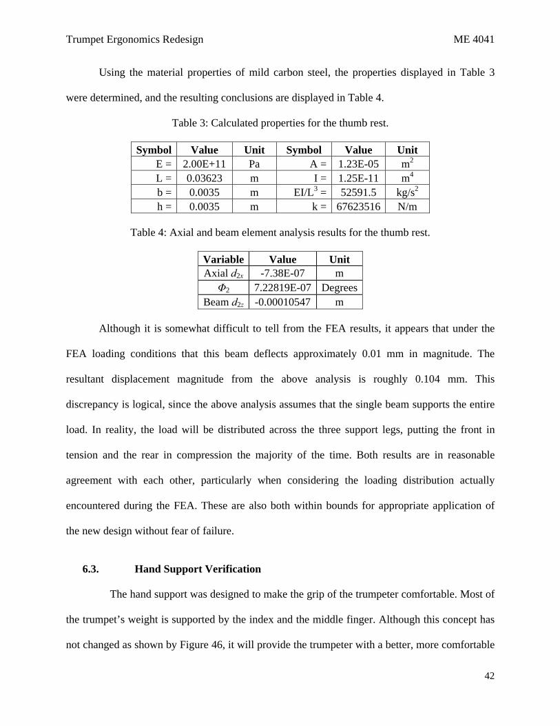
Using the material properties of mild carbon steel, the properties displayed in Table 3
were determined, and the resulting conclusions are displayed in Table 4.
Table 3: Calculated properties for the thumb rest.
Symbol Value Unit Symbol Value Unit E = 2.00E+11 Pa A = 1.23E-05 m2 L = 0.03623 m I = 1.25E-11 m4 b = 0.0035 m EI/L3 = 52591.5 kg/s2 h = 0.0035 m k = 67623516 N/m
Table 4: Axial and beam element analysis results for the thumb rest.
Variable Value Unit Axial d2x -7.38E-07 m Φ2 7.22819E-07 Degrees
Beam d2z -0.00010547 m
Although it is somewhat difficult to tell from the FEA results, it appears that under the
FEA loading conditions that this beam deflects approximately 0.01 mm in magnitude. The
resultant displacement magnitude from the above analysis is roughly 0.104 mm. This
discrepancy is logical, since the above analysis assumes that the single beam supports the entire
load. In reality, the load will be distributed across the three support legs, putting the front in
tension and the rear in compression the majority of the time. Both results are in reasonable
agreement with each other, particularly when considering the loading distribution actually
encountered during the FEA. These are also both within bounds for appropriate application of
the new design without fear of failure.
6.3. Hand Support Verification
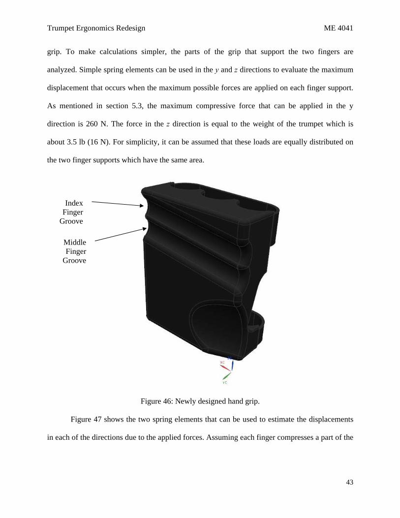
The hand support was designed to make the grip of the trumpeter comfortable. Most of
the trumpet’s weight is supported by the index and the middle finger. Although this concept has
not changed as shown by Figure 46, it will provide the trumpeter with a better, more comfortable
Trumpet Ergonomics Redesign ME 4041
43
grip. To make calculations simpler, the parts of the grip that support the two fingers are
analyzed. Simple spring elements can be used in the y and z directions to evaluate the maximum
displacement that occurs when the maximum possible forces are applied on each finger support.
As mentioned in section 5.3, the maximum compressive force that can be applied in the y
direction is 260 N. The force in the z direction is equal to the weight of the trumpet which is
about 3.5 lb (16 N). For simplicity, it can be assumed that these loads are equally distributed on
the two finger supports which have the same area.
Figure 46: Newly designed hand grip.
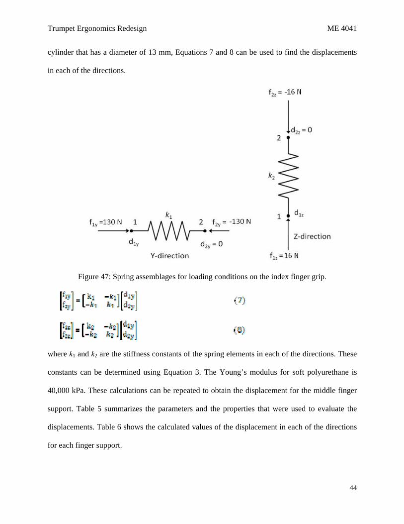
Figure 47 shows the two spring elements that can be used to estimate the displacements
in each of the directions due to the applied forces. Assuming each finger compresses a part of the
Index Finger
Groove
Middle Finger
Groove
Trumpet Ergonomics Redesign ME 4041
44
cylinder that has a diameter of 13 mm, Equations 7 and 8 can be used to find the displacements
in each of the directions.
Figure 47: Spring assemblages for loading conditions on the index finger grip.
where k1 and k2 are the stiffness constants of the spring elements in each of the directions. These
constants can be determined using Equation 3. The Young’s modulus for soft polyurethane is
40,000 kPa. These calculations can be repeated to obtain the displacement for the middle finger
support. Table 5 summarizes the parameters and the properties that were used to evaluate the
displacements. Table 6 shows the calculated values of the displacement in each of the directions
for each finger support.

Trumpet Ergonomics Redesign ME 4041
45
Table 5: Calculated properties for the hand support.
Symbol Value Unit Symbol Value Unit E = 4.00E+07 Pa I1 = 2.45 x 10⁻¹⁰ m4 L = 0.085 m EI/L3 = 16 kg/s2 d = 0.013 m k1 = 571770 N/m
A1 = 0.00122 m2 k2 = 245044 N/m A2 = 0.000521 m2
Table 6: Displacements in each direction for the hand support.
Direction Displacement (mm) Y 0.23 Z 0.033
The net displacement using the spring element approximation is about 0.23 mm. The
approximation of the displacement obtained for the same loading conditions using FEA in NX
was 0.0547 mm. The difference is expected because the model used for hand calculations is very
simplified. The minimum distance between the groove and the top edge of the grip is 6.5 mm.
Since the displacements are much smaller than this value, it is not a cause of concern. The shape
of the grip will not change significantly and is even expected to yield in order to provide
comfort.
7. Summary and Next Steps
Analysis of the deficiencies associated with current trumpet design yielded two areas of
improvement: reducing the difficulties associated with on-the-fly tuning using the forward and
rear tuning slides and increasing user comfort. After initial modeling of the original trumpet
design, three components were designed and modeled to address these issues. The forward ring
slides were adjusted to fit the ring size of the user more closely to avoid the delay caused by the
movement of the finger within the slide ring. The rear slide thumb rest was moved to a position
Trumpet Ergonomics Redesign ME 4041
46
in which the right hand thumb could adjust the rear tuning slide rather than the left thumb. It was
also redesigned to improve ergonomics and more tightly fit the standard thumb. Finally, a hand
rest was developed to distribute the trumpet weight load on the left hand fingers and provide an
offset for the palm from the trumpet side.
It was shown through the use of FEA and confirmed by hand calculations that these
components were, for the most part, well designed and structurally sound for the application. The
smaller cross-section version of the ring slides was shown by both FEA and hand calculations to
not be appropriately designed for extreme loading applications and therefore would not be
suitable for development. However, stresses in the larger cross-sectional area were within
acceptable ranges. Displacements and stresses in the thumb rest and hand support were also
shown to be within acceptable ranges for the application under the most extreme loads possible,
as derived from the NASA study shown in Table 7 of Appendix A.
To continue developing these improvements, manufacturing studies would need to be
performed. Given the materials and shapes designed, appropriate manufacturing processes would
need to be determined, and the costs associated with that manufacturing would need to be
assessed. Possible redesigns would need to be developed in case the manufacturing costs were
prohibitive. Market studies would also need to be done to determine the interest in the
marketplace and to estimate the amount of possible sales associated with these additions. If
these studies confirmed the existence of an appropriate market, patents protecting the intellectual
property would be applied for, and a business plan for sales would be developed.
8. References
Trumpet Ergonomics Redesign ME 4041
47
1. NASA (2008). “Man-
Systems Integration Standards.” Volume 1, Section 4. National Aeronautics and Space
Administration. NASA-STD-3000 4060B.
2. NCEES (2011).
Fundamentals of Engineering Supplied-Reference Handbook, 8th edition. National
Council of Examiners for Engineering and Surveying. pp. 228.
3. Wikipedia (2011). “Scheme
Human Hand Bones.” Accessed 4/18/11.
http://en.wikipedia.org/wiki/File:Scheme_human_hand_bones-en.svg.
(This space intentionally left blank.)

Trumpet Ergonomics Redesign ME 4041
48
Appendix A: U.S. Civilian Body Dimensions & Hand and Finger Strengths
Trumpet Ergonomics Redesign ME 4041
49
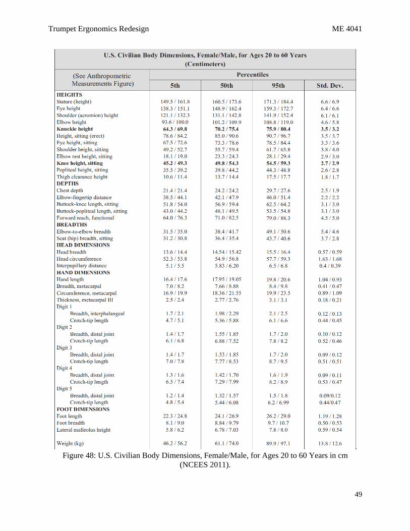
Figure 48: U.S. Civilian Body Dimensions, Female/Male, for Ages 20 to 60 Years in cm
(NCEES 2011).
Trumpet Ergonomics Redesign ME 4041
50
Figure 49: Human hand bone scheme.
Table 7: Hand, thumb, and finger strengths for males in (N) (NASA 2008).