Embed Size (px)
Citation preview
07/30/07 22:58 107/30/07 1
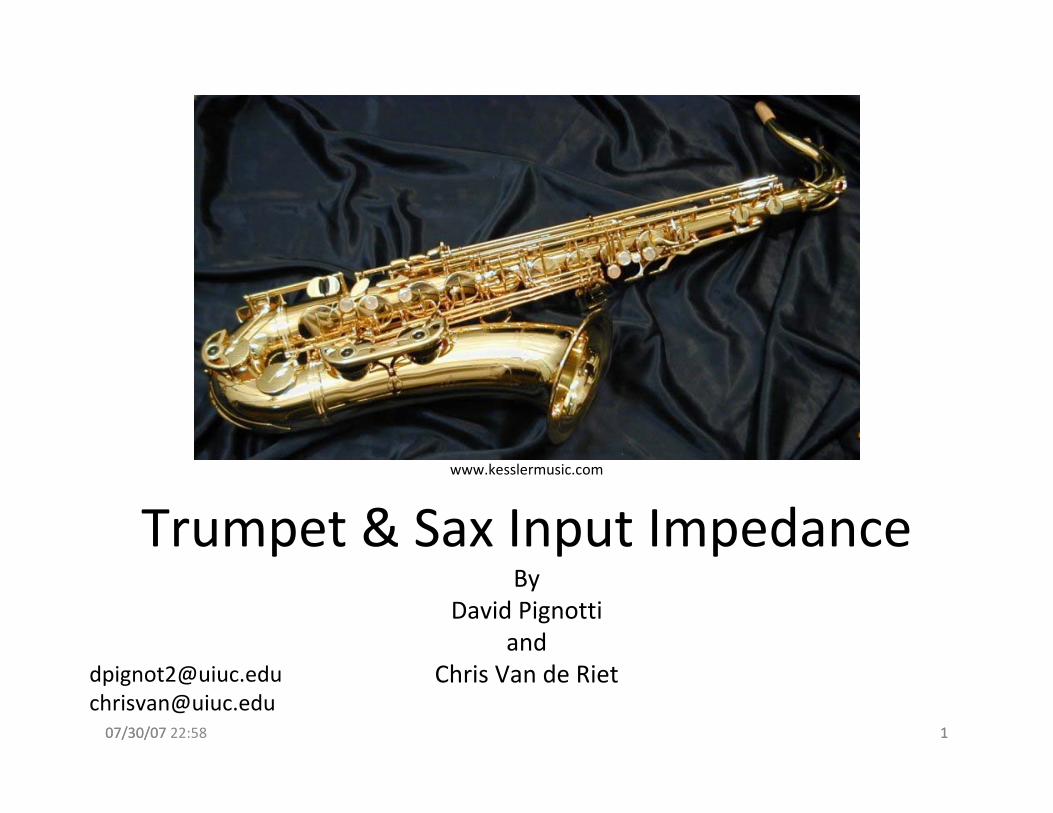
Trumpet & Sax Input ImpedanceBy
David Pignottiand
Chris Van de [email protected]@uiuc.edu
www.kesslermusic.com

07/30/07 22:58 207/30/07 2
Outline of Presentation:• Acoustics and Saxophone Overview
• Impedance and Construction of a Trumpet
• Experimental Apparatus
• Speed of Sound Measurements
• Future Work
8/25/2007 11:14 AM 38/25/2007 3
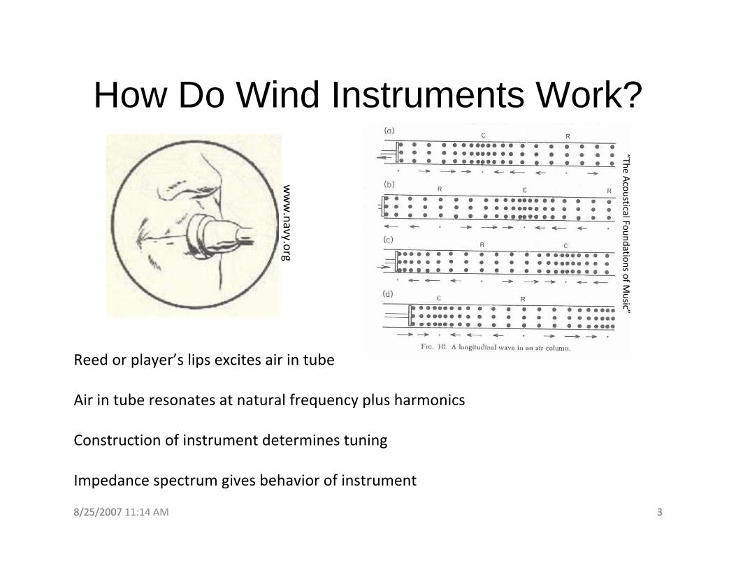
How Do Wind Instruments Work?
Reed or player’s lips excites air in tube
Air in tube resonates at natural frequency plus harmonics
Construction of instrument determines tuning
Impedance spectrum gives behavior of instrument
www.navy.org
“The Acoustical Foundations of M
usic”
07/30/07 22:58 407/30/07 4
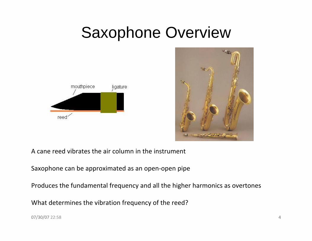
Saxophone Overview
A cane reed vibrates the air column in the instrument
Saxophone can be approximated as an open‐open pipe
Produces the fundamental frequency and all the higher harmonics as overtones
What determines the vibration frequency of the reed?
www.usd.edu

07/30/07 20:17 507/30/07 5
Acoustical impedance is a measure of resistance to putting a pressure wave though a tube
At impedance mismatches (bell end of trumpet), pressure waves are reflected back to player’s lips (or the reed for woodwinds)
Reflected waves give player’s lips (or the reed) “information” on vibration frequency
Acoustical intensity is the product of pressure and particle velocity, I = PU
8/25/2007 11:14 AM 68/25/2007 6
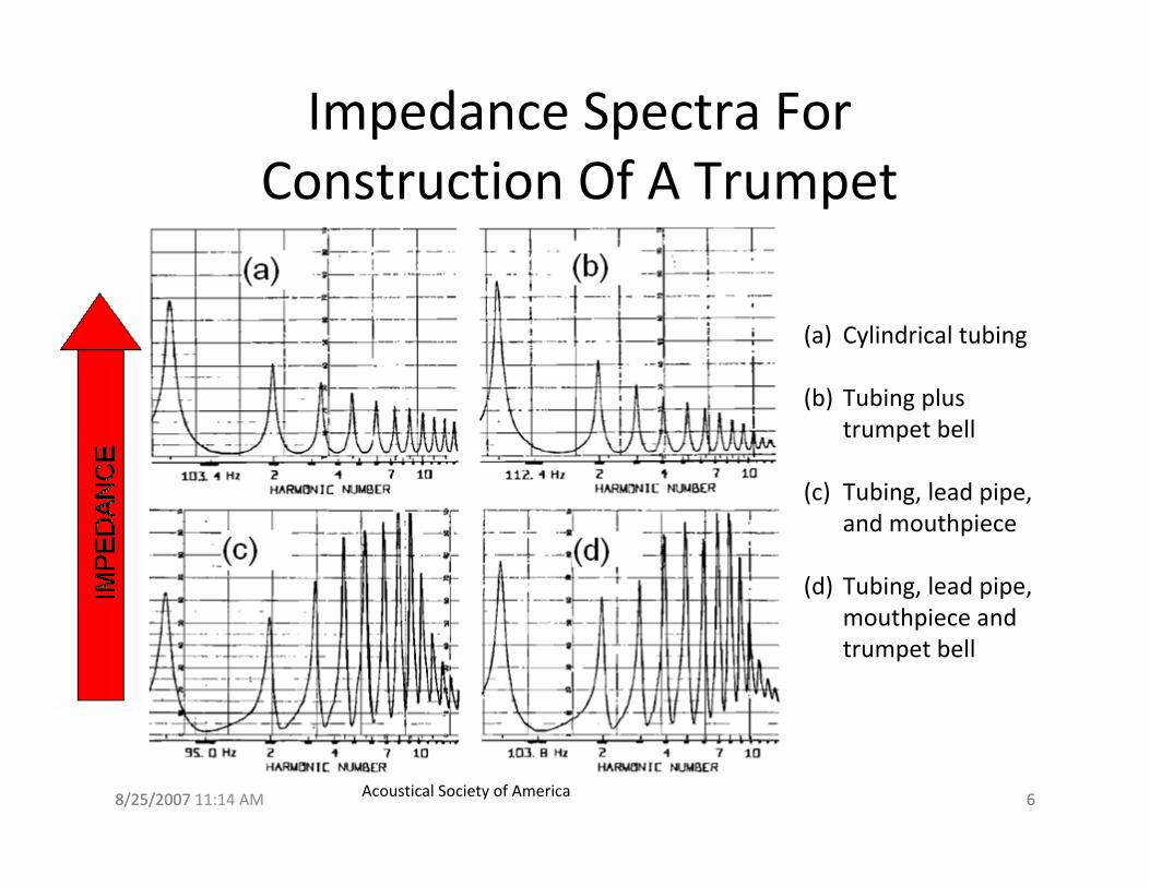
Impedance Spectra For Construction Of A Trumpet
(a) Cylindrical tubing
(b) Tubing plus trumpet bell
(c) Tubing, lead pipe, and mouthpiece
(d) Tubing, lead pipe, mouthpiece and trumpet bell
Acoustical Society of America
07/30/07 20:17 707/30/07 7
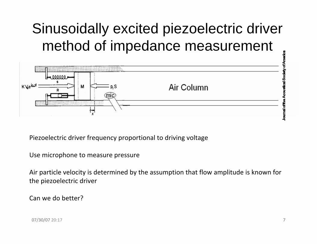
Sinusoidally excited piezoelectric driver method of impedance measurement
Piezoelectric driver frequency proportional to driving voltage
Use microphone to measure pressure
Air particle velocity is determined by the assumption that flow amplitude is known for the piezoelectric driver
Can we do better?

07/30/07 22:58 807/30/07 8
Our Plans To Get Impedance SpectrumExcite the air with a piezoelectric transducer
Measure pressure using an electret microphone
Measure particle velocity using a pressure‐differential microphone
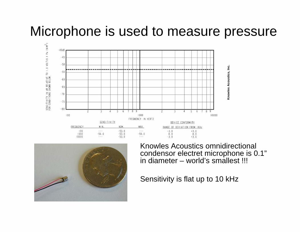
Microphone is used to measure pressure
Knowles Acoustics omnidirectionalcondensor electret microphone is 0.1”in diameter – world’s smallest !!!
Sensitivity is flat up to 10 kHz
Kno
wle
s A
cous
tics,
Inc.

Pressure-differential microphone is used to measure particle velocity
Modified RadioShack condenser microphone (Part # 270-090)
Removed back of microphone to expose both sides of the pressure gradient transducer
Integrate differential-pressure signal to get value proportional to particle velocity
Flat frequency response from 30→3000 Hz
[ ]1 20
1 ( ) ( )t
u p t p t dtdρ −∞
′ ′ ′= − −∫
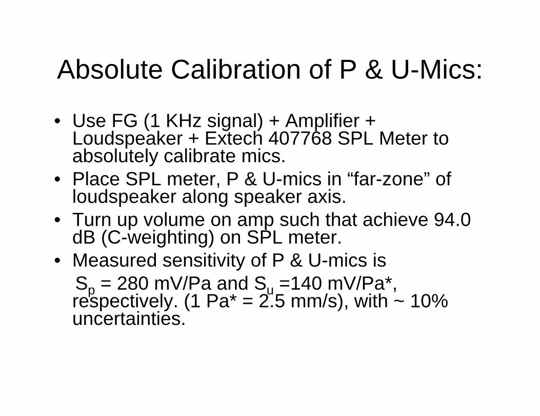
Absolute Calibration of P & U-Mics:
• Use FG (1 KHz signal) + Amplifier + Loudspeaker + Extech 407768 SPL Meter to absolutely calibrate mics.
• Place SPL meter, P & U-mics in “far-zone” of loudspeaker along speaker axis.
• Turn up volume on amp such that achieve 94.0 dB (C-weighting) on SPL meter.
• Measured sensitivity of P & U-mics is Sp = 280 mV/Pa and Su =140 mV/Pa*, respectively. (1 Pa* = 2.5 mm/s), with ~ 10% uncertainties.

Pressure Results: Trumpet-Sax Comparison
Both instruments were playing concert-pitch Ab (103.83 Hz for the sax, and 207.66 Hz for the trumpet)
Discrepancies at higher frequencies could be due to the nature of the instruments (with the trumpet, the higher frequencies are intended to be excited by the player, while with the sax, they merely “color” the sound)

Saxophone |P|, |U| Data:
1/f ventilation noise dominates the data at low frequencies
Particle velocity graph shows consistent shape of peaks

Saxophone |Z|, <|I|> Data:
1/f ventilation noise is still an issue in these plots
Impedance graph showssymmetry about peaks
Impedance graph alsoshows the fundamental isnot the easiest note to playusing this key configuration
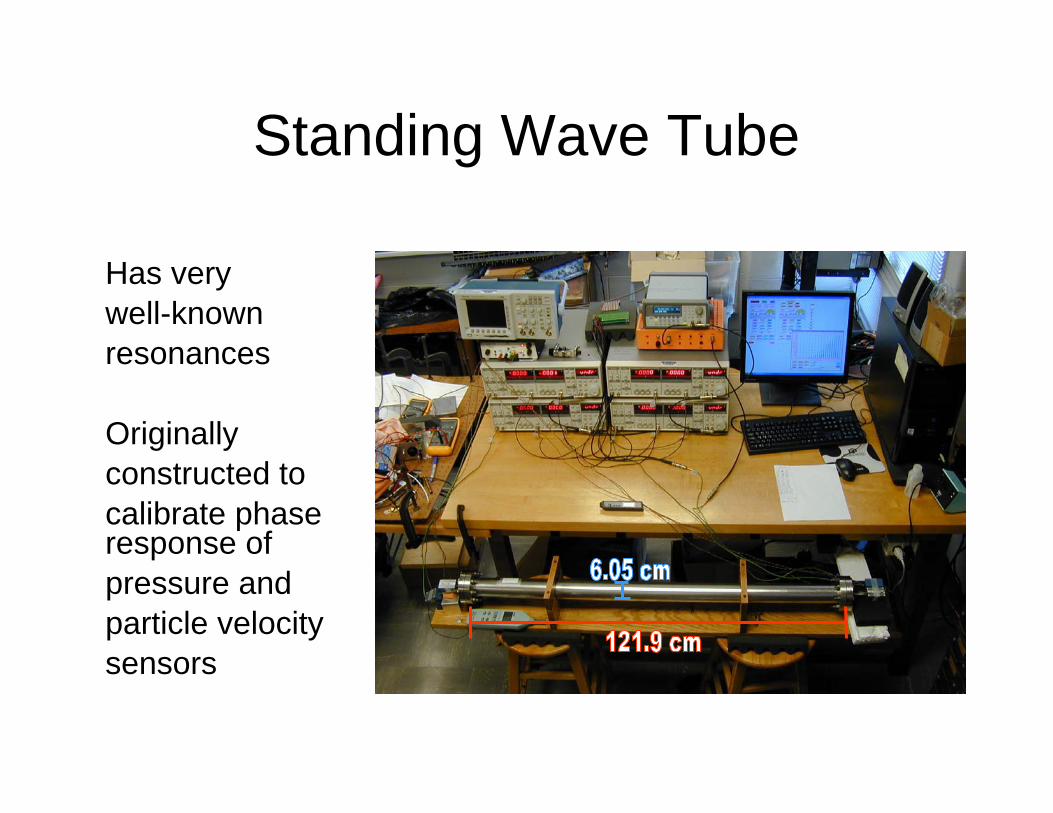
Standing Wave Tube
Has very well-knownresonances
Originallyconstructed tocalibrate phase response of pressure andparticle velocitysensors
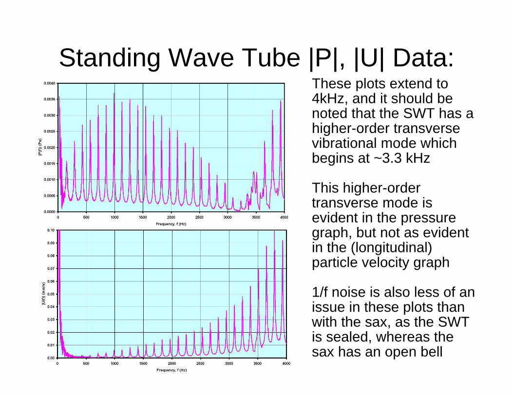
Standing Wave Tube |P|, |U| Data:These plots extend to 4kHz, and it should be noted that the SWT has a higher-order transverse vibrational mode which begins at ~3.3 kHz
This higher-order transverse mode is evident in the pressure graph, but not as evident in the (longitudinal) particle velocity graph
1/f noise is also less of an issue in these plots than with the sax, as the SWT is sealed, whereas the sax has an open bell

Standing Wave Tube |Z|, <|I|> Data:Impedance peaks are sharp, but the presence of 1/f ventilation noise (in the U-data) is an issue…
The lack of numerous impedance peaks explains why the SWT is a rather uninteresting musical instrument
The onset of the higher-order mode of the SWT is clearly visible in the both graphs
Note: The intensity graph’s vertical axis is displayed on a logarithmic scale

A measurement of the speed of sound was desired for calibration of the standing wave tube
Used a small piezoelectric speaker driven by 1-100 µs pulses from a function generator to excite sound waves in free air
Pressure microphone was placed a known distance from the speaker
Both the pulsed signal from the function generator and output of the microphone were observed on a Tektronix 3052B oscilloscope.
Measured time of propagation from the speaker to the microphone over a range of distances up to 50 cm
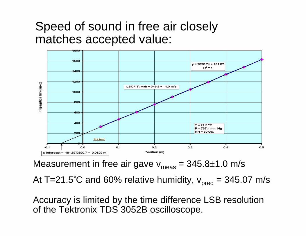
Measurement in free air gave vmeas = 345.8±1.0 m/s
At T=21.5°C and 60% relative humidity, vpred = 345.07 m/s
Accuracy is limited by the time difference LSB resolution of the Tektronix TDS 3052B oscilloscope.
Speed of sound in free air closely matches accepted value:

SWT Speed of Sound
Variations in the speed of sound with resonance frequency were observed in the standing wave tube (<vair> = 342.4 m/s measured, vs. vair = 345.8 m/s that we measured in free air). See graph on next page…
Analogous to EM waves propagating inside waveguides!

SWT Speed of Sound
n.b. Direct measurement of speed of sound in SWT using 10 μS pulses gave:
Vair = 341.0±0.5 m/s
SWT Speed of Sound
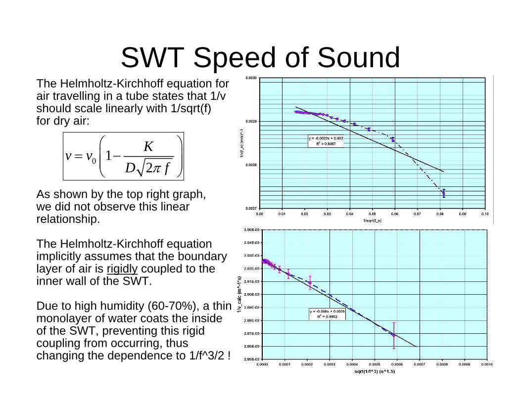
As shown by the top right graph, we did not observe this linear relationship.
The Helmholtz-Kirchhoff equation implicitly assumes that the boundary layer of air is rigidly coupled to the inner wall of the SWT.
Due to high humidity (60-70%), a thin monolayer of water coats the inside of the SWT, preventing this rigid coupling from occurring, thus changing the dependence to 1/f^3/2 !
The Helmholtz-Kirchhoff equation for air travelling in a tube states that 1/v should scale linearly with 1/sqrt(f)for dry air:
0 12Kv v
D fπ
⎛ ⎞= −⎜ ⎟⎜ ⎟
⎝ ⎠
07/30/07 22:58 2307/30/07 23
Long-term Plans:• Collect more data (and buy more lock-ins… ☺ )
• Construction of three-dimensional air particle velocity sensor
• “Universal” apparatus: can be used for measuring complex Z = p/u and I = pu for any wind instrument, as well as for arbitrary sound fields!
Questions? Email- [email protected]
Special thanks to Prof. Steve Errede.


![Finale 2008 - [Salamanca Samba.MUS]b b b b b b b b 1st Eb Alto Sax 2nd Eb Alto Sax 1st Bb Tenor Sax 2nd Bb Tenor Sax Eb Baritone Sax 1st Bb Trumpet 2nd Bb Trumpet 3rd Bb Trumpet 4th](https://img.pdfslide.net/doc/110x75/5eaaa15cfd3cb15ffc5b52df/finale-2008-salamanca-sambamus-b-b-b-b-b-b-b-b-1st-eb-alto-sax-2nd-eb-alto.jpg)