Embed Size (px)
Citation preview
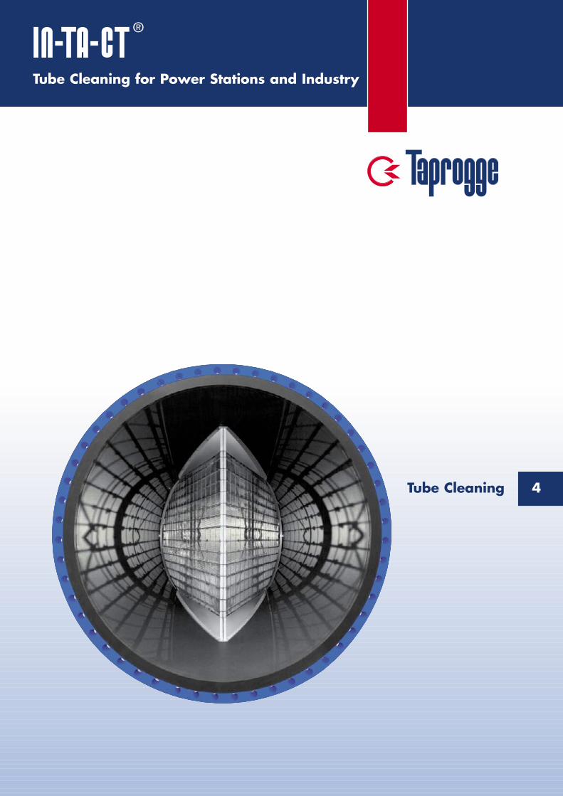
Tube Cleaning for Power Stations and Industry
4Tube Cleaning
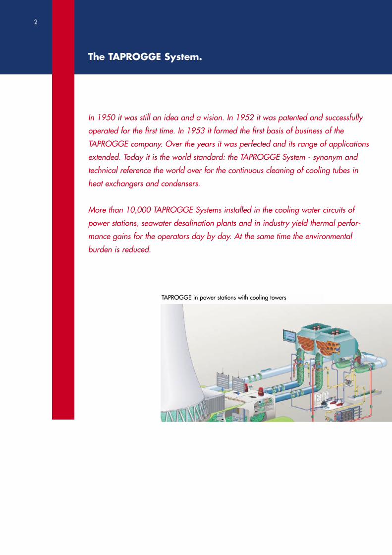
In 1950 it was still an idea and a vision. In 1952 it was patented and successfully
operated for the first time. In 1953 it formed the first basis of business of the
TAPROGGE company. Over the years it was perfected and its range of applications
extended. Today it is the world standard: the TAPROGGE System - synonym and
technical reference the world over for the continuous cleaning of cooling tubes in
heat exchangers and condensers.
More than 10,000 TAPROGGE Systems installed in the cooling water circuits of
power stations, seawater desalination plants and in industry yield thermal perfor-
mance gains for the operators day by day. At the same time the environmental
burden is reduced.
The TAPROGGE System.
TAPROGGE in power stations with cooling towers
2
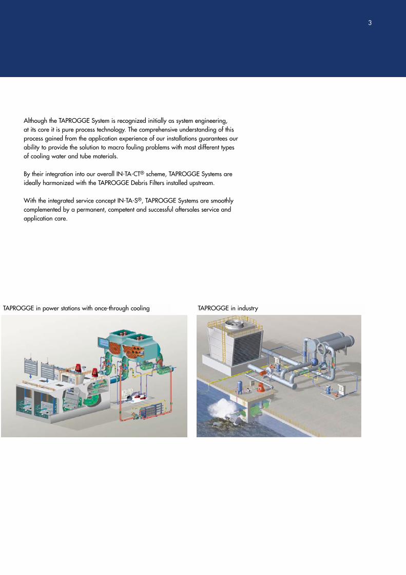
Although the TAPROGGE System is recognized initially as system engineering, at its core it is pure process technology. The comprehensive understanding of thisprocess gained from the application experience of our installations guarantees ourability to provide the solution to macro fouling problems with most different typesof cooling water and tube materials.
By their integration into our overall IN-TA-CT® scheme, TAPROGGE Systems areideally harmonized with the TAPROGGE Debris Filters installed upstream.
With the integrated service concept IN-TA-S®, TAPROGGE Systems are smoothlycomplemented by a permanent, competent and successful aftersales service andapplication care.
TAPROGGE in power stations with once-through cooling TAPROGGE in industry
3
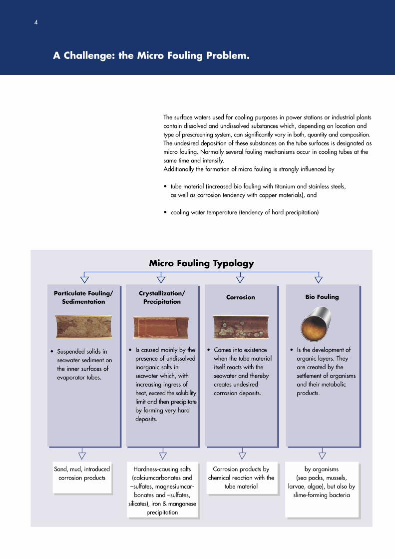
The surface waters used for cooling purposes in power stations or industrial plantscontain dissolved and undissolved substances which, depending on location andtype of prescreening system, can significantly vary in both, quantity and composition.The undesired deposition of these substances on the tube surfaces is designated asmicro fouling. Normally several fouling mechanisms occur in cooling tubes at thesame time and intensify. Additionally the formation of micro fouling is strongly influenced by
• tube material (increased bio fouling with titanium and stainless steels, as well as corrosion tendency with copper materials), and
• cooling water temperature (tendency of hard precipitation)
A Challenge: the Micro Fouling Problem.
4
Micro Fouling Typology
Particulate Fouling/Sedimentation
Crystallization/Precipitation
Corrosion Bio Fouling
Sand, mud, introducedcorrosion products
Hardness-causing salts(calciumcarbonates and
–sulfates, magnesiumcar-bonates and –sulfates,
silicates), iron & manganeseprecipitation
Corrosion products by chemical reaction with the
tube material
by organisms(sea pocks, mussels,
larvae, algae), but also byslime-forming bacteria
• Suspended solids inseawater sediment onthe inner surfaces of evaporator tubes.
• Is caused mainly by thepresence of undissolvedinorganic salts in seawater which, with increasing ingress of heat, exceed the solubilitylimit and then precipitateby forming very hard deposits.
• Comes into existencewhen the tube materialitself reacts with the seawater and thereby creates undesired corrosion deposits.
• Is the development of organic layers. They are created by the settlement of organisms and their metabolic products.
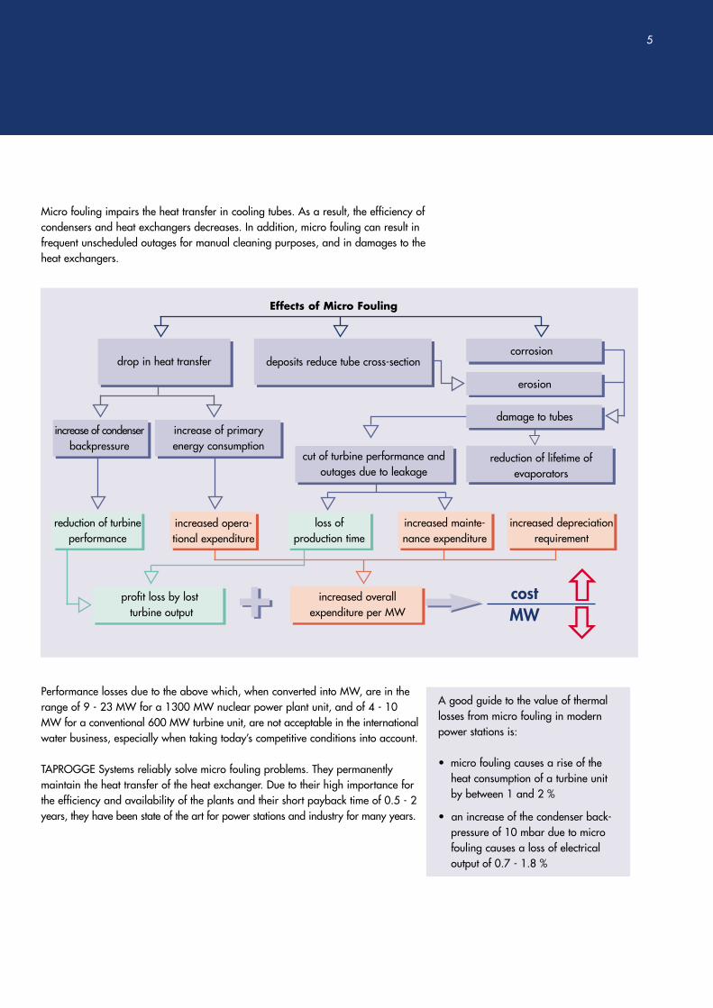
Micro fouling impairs the heat transfer in cooling tubes. As a result, the efficiency ofcondensers and heat exchangers decreases. In addition, micro fouling can result infrequent unscheduled outages for manual cleaning purposes, and in damages to theheat exchangers.
Performance losses due to the above which, when converted into MW, are in therange of 9 - 23 MW for a 1300 MW nuclear power plant unit, and of 4 - 10MW for a conventional 600 MW turbine unit, are not acceptable in the internationalwater business, especially when taking today’s competitive conditions into account.
TAPROGGE Systems reliably solve micro fouling problems. They permanentlymaintain the heat transfer of the heat exchanger. Due to their high importance forthe efficiency and availability of the plants and their short payback time of 0.5 - 2years, they have been state of the art for power stations and industry for many years.
A good guide to the value of thermallosses from micro fouling in modernpower stations is:
• micro fouling causes a rise of theheat consumption of a turbine unitby between 1 and 2 %
• an increase of the condenser back-pressure of 10 mbar due to microfouling causes a loss of electrical output of 0.7 - 1.8 %
5
Effects of Micro Fouling
drop in heat transfer
increase of condenserbackpressure
profit loss by lostturbine output
increased overall expenditure per MW
increase of primary energy consumption
increased opera-tional expenditure
loss of production time
increased mainte-nance expenditure
increased depreciationrequirement
reduction of lifetime of evaporators
damage to tubes
deposits reduce tube cross-sectioncorrosion
erosion
+ costMW+
reduction of turbineperformance
cut of turbine performance andoutages due to leakage
From the Idea to the Solution.
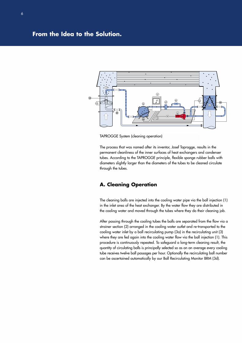
The process that was named after its inventor, Josef Taprogge, results in the permanent cleanliness of the inner surfaces of heat exchangers and condensertubes. According to the TAPROGGE principle, flexible sponge rubber balls withdiameters slightly larger than the diameters of the tubes to be cleaned circulatethrough the tubes.
The cleaning balls are injected into the cooling water pipe via the ball injection (1)in the inlet area of the heat exchanger. By the water flow they are distributed inthe cooling water and moved through the tubes where they do their cleaning job.
After passing through the cooling tubes the balls are separated from the flow via astrainer section (2) arranged in the cooling water outlet and re-transported to thecooling water inlet by a ball recirculating pump (3a) in the recirculating unit (3)where they are fed again into the cooling water flow via the ball injection (1). Thisprocedure is continuously repeated. To safeguard a long-term cleaning result, thequantity of circulating balls is principally selected so as on an average every coolingtube receives twelve ball passages per hour. Optionally the recirculating ball numbercan be ascertained automatically by our Ball Recirculating Monitor BRM (3d).
A. Cleaning Operation
6
TAPROGGE System (cleaning operation)
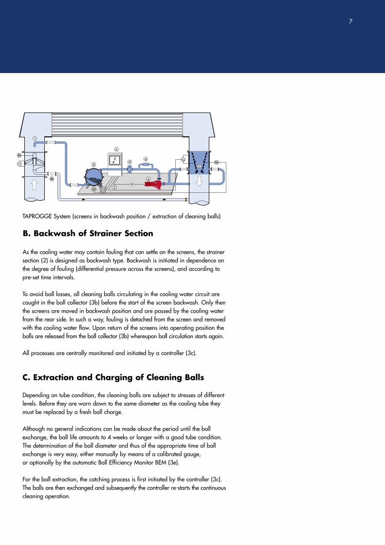
B. Backwash of Strainer Section
C. Extraction and Charging of Cleaning Balls
As the cooling water may contain fouling that can settle on the screens, the strainersection (2) is designed as backwash type. Backwash is initiated in dependence onthe degree of fouling (differential pressure across the screens), and according topre-set time intervals.
To avoid ball losses, all cleaning balls circulating in the cooling water circuit arecaught in the ball collector (3b) before the start of the screen backwash. Only thenthe screens are moved in backwash position and are passed by the cooling waterfrom the rear side. In such a way, fouling is detached from the screen and removedwith the cooling water flow. Upon return of the screens into operating position theballs are released from the ball collector (3b) whereupon ball circulation starts again.
All processes are centrally monitored and initiated by a controller (3c).
Depending on tube condition, the cleaning balls are subject to stresses of differentlevels. Before they are worn down to the same diameter as the cooling tube theymust be replaced by a fresh ball charge.
Although no general indications can be made about the period until the ballexchange, the ball life amounts to 4 weeks or longer with a good tube condition.The determination of the ball diameter and thus of the appropriate time of ballexchange is very easy, either manually by means of a calibrated gauge, or optionally by the automatic Ball Efficiency Monitor BEM (3e).
For the ball extraction, the catching process is first initiated by the controller (3c).The balls are then exchanged and subsequently the controller re-starts the continuouscleaning operation.
7
TAPROGGE System (screens in backwash position / extraction of cleaning balls)
A modular Construction Kit.
From our application experience gained through more than 10,000 installations in different cooling water qualities of the world, the TAPROGGE System has beenperfected over the years and now constitutes a sophisticated modular constructionkit that is able to meet the full extent of the operators’ requirement profiles.
The packaging of the modules to suit the relevant operational environment is thedaily task of our project and planning engineers. They make use of a basic kit thatmay optionally be complemented by further components.
The basic Construction Kit. In the basic Version, the
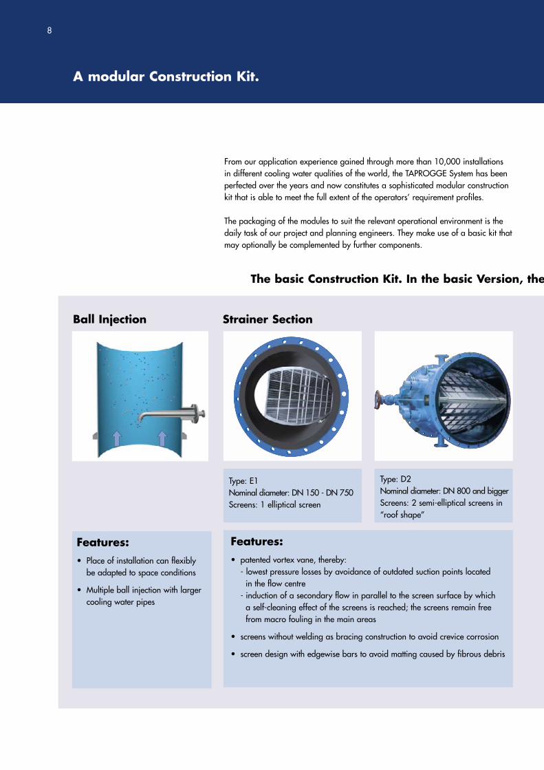
Ball Injection Strainer Section
Features:• patented vortex vane, thereby:
- lowest pressure losses by avoidance of outdated suction points located in the flow centre
- induction of a secondary flow in parallel to the screen surface by which a self-cleaning effect of the screens is reached; the screens remain freefrom macro fouling in the main areas
• screens without welding as bracing construction to avoid crevice corrosion
• screen design with edgewise bars to avoid matting caused by fibrous debris
Features:• Place of installation can flexibly
be adapted to space conditions
• Multiple ball injection with larger cooling water pipes
Type: D2Nominal diameter: DN 800 and biggerScreens: 2 semi-elliptical screens in“roof shape”
Type: E1Nominal diameter: DN 150 - DN 750Screens: 1 elliptical screen
8
TAPROGGE System comprises 3 Components:
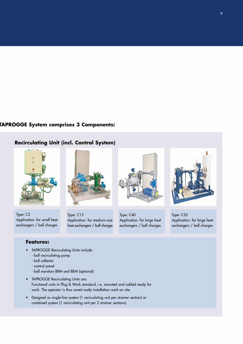
Recirculating Unit (incl. Control System)
Type: C3Application: for small heatexchangers / ball charges
Type: C40Application: for large heatexchangers / ball charges
Type: C13Application: for medium-sizeheat exchangers / ball charges
Type: C55Application: for large heatexchangers / ball charges
Features:• TAPROGGE Recirculating Units include:
- ball recirculating pump- ball collector- control panel- ball monitors BRM and BEM (optional)
• TAPROGGE Recirculating Units are:Functional units in Plug & Work standard, i.e. mounted and cabled ready forwork. The operator is thus saved costly installation work on site.
• Designed as single-line system (1 recirculating unit per strainer section) orcombined system (1 recirculating unit per 2 strainer sections).
9
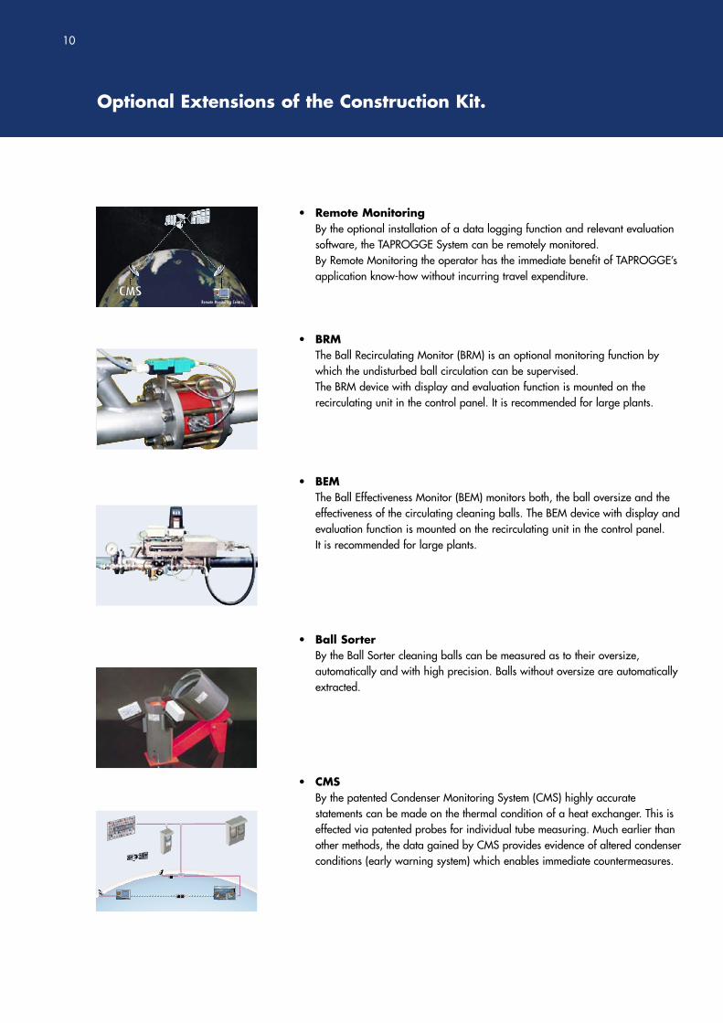
• Remote MonitoringBy the optional installation of a data logging function and relevant evaluationsoftware, the TAPROGGE System can be remotely monitored. By Remote Monitoring the operator has the immediate benefit of TAPROGGE’sapplication know-how without incurring travel expenditure.
• BRMThe Ball Recirculating Monitor (BRM) is an optional monitoring function bywhich the undisturbed ball circulation can be supervised.The BRM device with display and evaluation function is mounted on therecirculating unit in the control panel. It is recommended for large plants.
• BEMThe Ball Effectiveness Monitor (BEM) monitors both, the ball oversize and theeffectiveness of the circulating cleaning balls. The BEM device with display andevaluation function is mounted on the recirculating unit in the control panel. It is recommended for large plants.
• Ball SorterBy the Ball Sorter cleaning balls can be measured as to their oversize, automatically and with high precision. Balls without oversize are automatically extracted.
• CMSBy the patented Condenser Monitoring System (CMS) highly accurate statements can be made on the thermal condition of a heat exchanger. This iseffected via patented probes for individual tube measuring. Much earlier thanother methods, the data gained by CMS provides evidence of altered condenserconditions (early warning system) which enables immediate countermeasures.
Remote Monitoring Centre
Sponge Ball Efficiency
run time [d]
120
100
80
60
40
20
00 10 20 30 40 50 60
%
Sponge Ball Efficiency
run time [d]
120
100
80
60
40
20
00 10 20 30 40 50 60
%Sponge Ball Efficiency
run time [d]
120
100
80
60
40
20
00 10 20 30 40 50 60
%
TAPRTAPROGGEOGGEEFFIEFFICIENCYPARTNERSHIPARTNERSHIP
TAPROGGEEFFICIENCYPARTNERSHIP
TAPROGGEEFFICIENCYPARTNERSHIP
Optional Extensions of the Construction Kit.
10
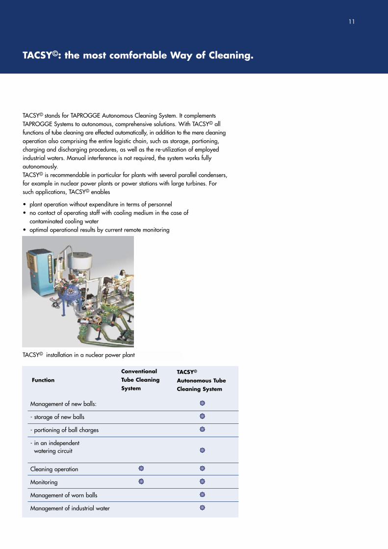
TACSY© stands for TAPROGGE Autonomous Cleaning System. It complementsTAPROGGE Systems to autonomous, comprehensive solutions. With TACSY© allfunctions of tube cleaning are effected automatically, in addition to the mere cleaningoperation also comprising the entire logistic chain, such as storage, portioning,charging and discharging procedures, as well as the re-utilization of employedindustrial waters. Manual interference is not required, the system works fully autonomously.TACSY© is recommendable in particular for plants with several parallel condensers,for example in nuclear power plants or power stations with large turbines. Forsuch applications, TACSY© enables
• plant operation without expenditure in terms of personnel• no contact of operating staff with cooling medium in the case of
contaminated cooling water• optimal operational results by current remote monitoring
TACSY©: the most comfortable Way of Cleaning.
Management of new balls:
- storage of new balls
- portioning of ball charges
- in an independentwatering circuit
Cleaning operation
Monitoring
Management of worn balls
Management of industrial water
Function
ConventionalTube Cleaning System
TACSY©
Autonomous TubeCleaning System
11
TACSY© installation in a nuclear power plant
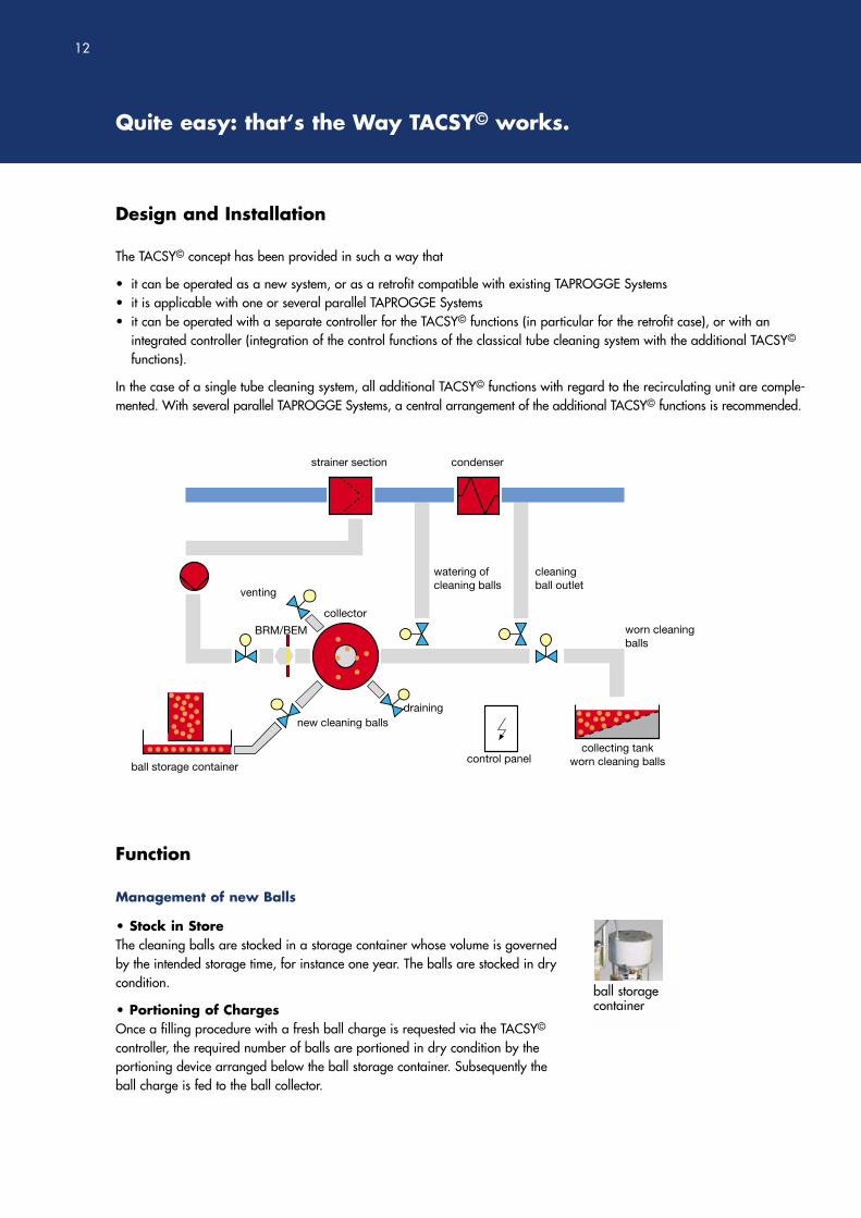
Design and Installation
Quite easy: that‘s the Way TACSY© works.
The TACSY© concept has been provided in such a way that
• it can be operated as a new system, or as a retrofit compatible with existing TAPROGGE Systems• it is applicable with one or several parallel TAPROGGE Systems• it can be operated with a separate controller for the TACSY© functions (in particular for the retrofit case), or with an
integrated controller (integration of the control functions of the classical tube cleaning system with the additional TACSY©
functions).
In the case of a single tube cleaning system, all additional TACSY© functions with regard to the recirculating unit are comple-mented. With several parallel TAPROGGE Systems, a central arrangement of the additional TACSY© functions is recommended.
Function
Management of new Balls
• Stock in StoreThe cleaning balls are stocked in a storage container whose volume is governedby the intended storage time, for instance one year. The balls are stocked in drycondition.
• Portioning of ChargesOnce a filling procedure with a fresh ball charge is requested via the TACSY©
controller, the required number of balls are portioned in dry condition by the portioning device arranged below the ball storage container. Subsequently theball charge is fed to the ball collector.
strainer section
collector
condenser
venting
new cleaning ballsdraining
watering ofcleaning balls
cleaningball outlet
worn cleaningballs
control panel
BRM/BEM
collecting tankworn cleaning ballsball storage container
12
ball storage container
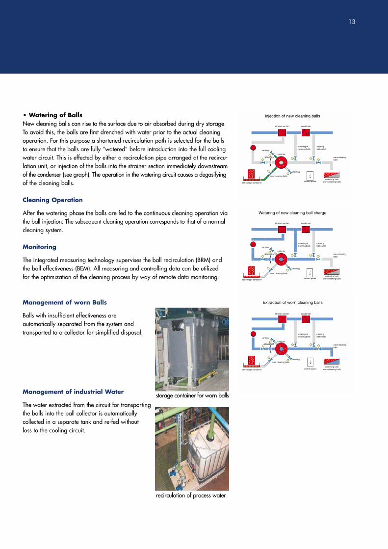
• Watering of BallsNew cleaning balls can rise to the surface due to air absorbed during dry storage.To avoid this, the balls are first drenched with water prior to the actual cleaningoperation. For this purpose a shortened recirculation path is selected for the ballsto ensure that the balls are fully “watered” before introduction into the full coolingwater circuit. This is effected by either a recirculation pipe arranged at the recircu-lation unit, or injection of the balls into the strainer section immediately downstreamof the condenser (see graph). The operation in the watering circuit causes a degasifyingof the cleaning balls.
Cleaning Operation
After the watering phase the balls are fed to the continuous cleaning operation viathe ball injection. The subsequent cleaning operation corresponds to that of a normalcleaning system.
Monitoring
The integrated measuring technology supervises the ball recirculation (BRM) andthe ball effectiveness (BEM). All measuring and controlling data can be utilized for the optimization of the cleaning process by way of remote data monitoring.
Management of worn Balls
Balls with insufficient effectiveness are automatically separated from the system and transported to a collector for simplified disposal.
Management of industrial Water
The water extracted from the circuit for transportingthe balls into the ball collector is automatically collected in a separate tank and re-fed without loss to the cooling circuit.
Injection of new cleaning balls
strainer section
collector
condenser
venting
new cleaning balls
draining
watering ofcleaning balls
cleaningball outlet
worn cleaningballs
control panel
BRM/BEM
collecting tankworn cleaning ballsball storage container
Extraction of worn cleaning balls
strainer section
collector
condenser
venting
new cleaning ballsdraining
watering ofcleaning balls
cleaningball outlet
worn cleaningballs
control panel
BRM/BEM
collecting tankworn cleaning ballsball storage container
Watering of new cleaning ball charge
strainer section
collector
condenser
venting
new cleaning balls
draining
watering ofcleaning balls
cleaningball outlet
worn cleaningballs
control panel
BRM/BEM
collecting tankworn cleaning ballsball storage container
13
storage container for worn balls
recirculation of process water
TAPROGGE Systems are Systems with added Value.
14
By TAPROGGE Systems you obtain:
• efficiency and availability by permanently constant heat transfer of your heat exchangers and condensers
• reduction of your primary energy cost, increase of your turbine output • relief of environmental burden by saved fuel (reduction of SO2, NOX, CO2)• longer lifetime of your thermal equipment• reduced corrosion in heat exchangers• avoidance of unscheduled shutdowns due to tube leakage
And TAPROGGE provides even more:
• Support in application technology at the planning stage. Prior to investment, tube examinations can provide valuable knowledge in viewof the feasibility and the extent of the future cleaning success. This assists the operator to make his investment decision wisely.
• Access to the most comprehensive ball assortment the world over. With the system the operator is provided only with a mechanism for the transport of thecleaning balls in the cooling water circuit. This alone does not yield a benefit.Benefit is created by the application-technological know-how of the relations among cooling water chemistry and biology (micro fouling), tube material and cleaning balls. The availability and optimal choice of ball type and cleaning mode are the keyto effective tube cleaning. That’s why TAPROGGE supports its customers with anunparalleled range of special cleaning balls. The quality standard and the varietyof ball types are an essential contribution to the success of our aftersales care.
• Expert know-how by IN-TA-S®. More than 50 TAPROGGE Service experts at 10international service bases provide the operators with maximum availability. More than 10,000 TAPROGGE Systems in over 100 countries of the world areproof of the know-how and experience of our international service team. In fact it can be proven that by making use of IN-TA-S® the yearly benefits exceed theinvestment value of the TAPROGGE System by far.
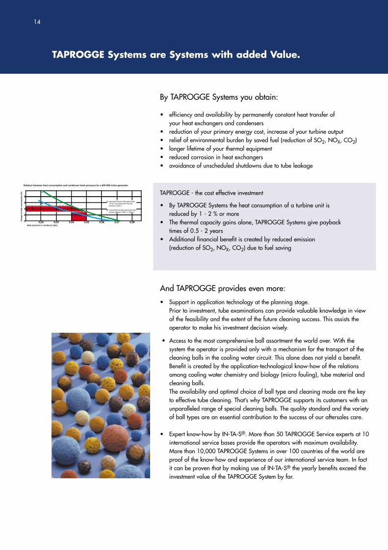
TAPROGGE - the cost effective investment
• By TAPROGGE Systems the heat consumption of a turbine unit is reduced by 1 - 2 % or more
• The thermal capacity gains alone, TAPROGGE Systems give payback times of 0.5 - 2 years
• Additional financial benefit is created by reduced emission(reduction of SO2, NOX, CO2) due to fuel saving
A
A
B
saturated-steam turbo-generator70 bar saturated with thermalreheat to 225¡ C
Conventional turbo-generator withreheat 180 bar / 530¡ C / 530¡ C
8
6
4
2
0 0,02 0,03 0,04 0,05 0,06 0,07 0,08
Relation between heat consumption and condenser back-pressure for a 600 MW turbo-generator
Back-pressure in condenser (bar)
Ch
ang
e o
f h
eat
con
sum
pti
on
(%
)
B
15
TAPROGGE Care & Comfort Package
Quality right from the Start
• Performance by TAPROGGE as per DIN EN ISO 9001• Safety of design by fulfilling the requirements of the European
Pressure Equipment Directive 97/23/EC• Application of a management system for safety, health and environmental
protection (SCC)• Standard documentation; documentation upon customer’s request, respectively• The use of extremely corrosion-resistant materials with long lifetimes safeguards
the preservation of the value of investment.
Compatibility by IN-TA-CT® Modules
• The TAPROGGE System is a modular element of IN-TA-CT®, our integral principle for the optimization of cooling water circuits.
• By combination with a TAPROGGE prescreening system and a TAPROGGE debris filter of our PR-BW series upstream, an effective overall solution presents itself for the protection from micro and macro fouling, from the intake to the heat exchanger or condenser. A complete solution - without interfaces - and inclusive of the TAPROGGE-Systemguarantee.
Competence and Experience out of one Hand
• Application consultancy, project management, fabrication, installation and commissioning of TAPROGGE Systems are available from TAPROGGE out of one source.
• With more than 12,000 successful applications, TAPROGGE can make use of itsapplication-technological experience in its special field that stands unparalleled the world over. This competence is indispensable for difficult media and unknowncleaning behaviour.
• In addition to that, the cooling water test circuits of TAPROGGE’s TechnologicalCentre allow a particularly reliable and cost-effective simulation of site conditions.
Comprehensive Operator Support by IN-TA-S®
• By the installation and commissioning of the TAPROGGE System, operators haveimmediate access to IN-TA-S®.
• By IN-TA-S®, TAPROGGE takes care of the operator in all questions of operationand maintenance. Scope, duration and frequency of the care can be determinedby the operator.
• Particularly quick support is available to the users of our Remote Monitoring Service.
Postal address:
TAPROGGE Gesellschaft mbH58292 WetterGermany
Company address:
TAPROGGE Gesellschaft mbHSchliemannstraße 2-1458300 WetterGermany
Tel.: +49 (0)2335 / 762-0Fax:+49 (0)2335 / 762-245
E-Mail: [email protected]: http://www.taprogge.de
© TAPROGGE Gesellschaft mbH. All rights reserved.TAPROGGE®, IN-TA-CT®, IN-TA-S® and TAPIS® are registered trademarks of TAPROGGE Gesellschaft mbH. 00
21-4
0030
1-01
-400
301-
02