Embed Size (px)
Citation preview

Tulkarem Multipurpose Sport Hall
Prepared by:Moatasem Ghanim
Abdul-Rahman AlsaabnehMalek Salatneh
Supervisor: Dr. Shaker Albitar
2
Contents
Chapter 1: Introduction
Chapter 2: Concrete Elements Design
Chapter 3: Steel Structure Design

3
Chapter 1: Introduction
4
Chapter 1: Introduction
•Overview
This project is a design of multipurpose sport hall with concrete walls, slabs and steel roof.
5
Chapter 1: Introduction
•Scope
The goal of the new design is to increase the hall capacity by adding more seats for audience and adding more storage area. The area of the building will remain the same, this is expected to increase the functionality of the hall.
6
Chapter 1: Introduction
•Codes of Design
This project is designed using- ACI 318-08.- IBC 2009.- AISC.
7
Chapter 1: Introduction
•Units of Measure
The units of measure used in this project are the SI units (meter, KN).
8
Chapter 1: Introduction
•Material Properties
The main materials used are:
• Concrete of ƒc= 28 Mpa.• Reinforcement Steel of Fy= 420 Mpa.• The properties of the Steel Structure’s material will mentioned
later.
9
Chapter 1: Introduction
•Loads
The design was performed considering gravity loads which include both, dead and live loads.
• Dead loads associated with the weight of structure itself.• Live loads is pre-determined by the IBC code with value of 3
KN/m².• The loads assigned to the roof will mentioned later.
10
Chapter 1: Introduction
•Description of Building and Location
- The hall consist of reinforced concrete walls and a steel roof.- The soil has a bearing capacity of 150 KN/m².

11
Chapter 1: Introduction
Two sets of spectators seats that are opposite to each other in the northern and southern sides. Both groups of seats can hold up to 525 persons. There are utility rooms for players beneath audience seats.The hall has an area of 1744 m²
12
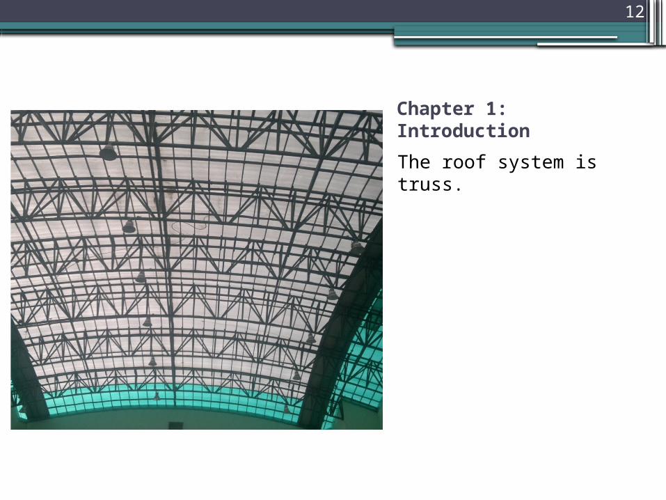
Chapter 1: Introduction
The roof system is truss.
13
Chapter 1: Introduction
•Modification of the Design
Number of seats is to be increased by 40% with increasing the number of storage area.
14
Chapter 2: Concrete Elements DesignDesign of Concrete Slabs
15
Design of Concrete Slabs
• Structural System
The structural system used was one way solid slab with different thicknesses. The thickness of each slab is shown in table 4 page 10.
16
Design of Concrete Slabs
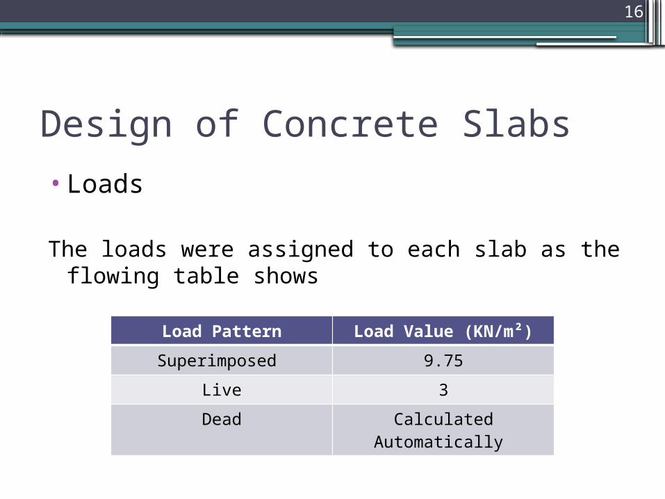
•Loads
The loads were assigned to each slab as the flowing table shows
Load Pattern Load Value (KN/m²)
Superimposed 9.75
Live 3
Dead Calculated Automatically

17
Design of Concrete Slabs
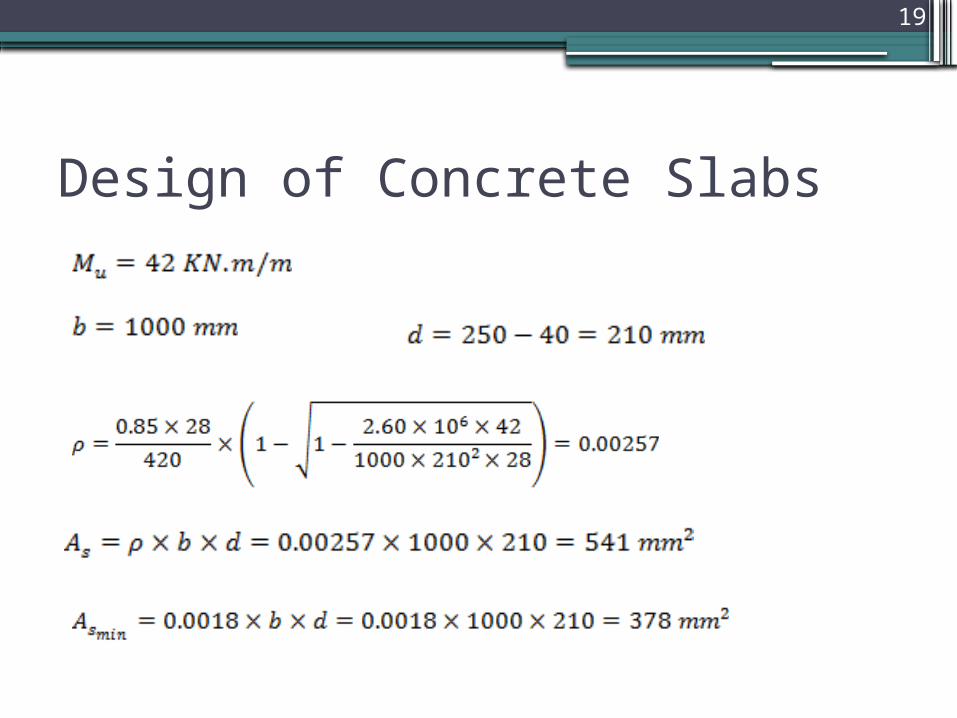
• Design Process
The methodology used here is to take the ultimate moment in each slab and design for it. Take slab 2 as an example. The plan of this slab is shown in the appendices drawings.

18
Design of Concrete Slabs
19
Design of Concrete Slabs
20
Design of Concrete Slabs
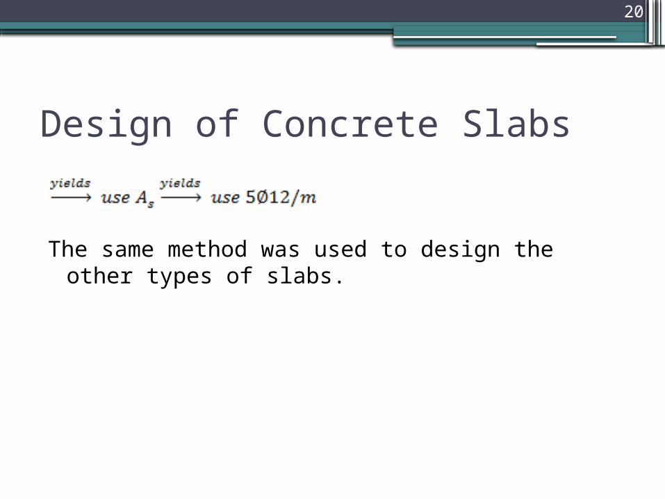
The same method was used to design the other types of slabs.
21
Chapter 2: Concrete Elements DesignDesign of Beams
22
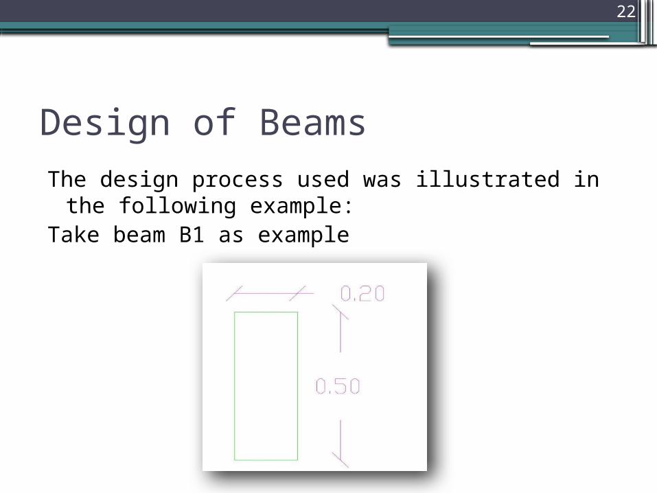
Design of BeamsThe design process used was illustrated in the following
example:Take beam B1 as example
23
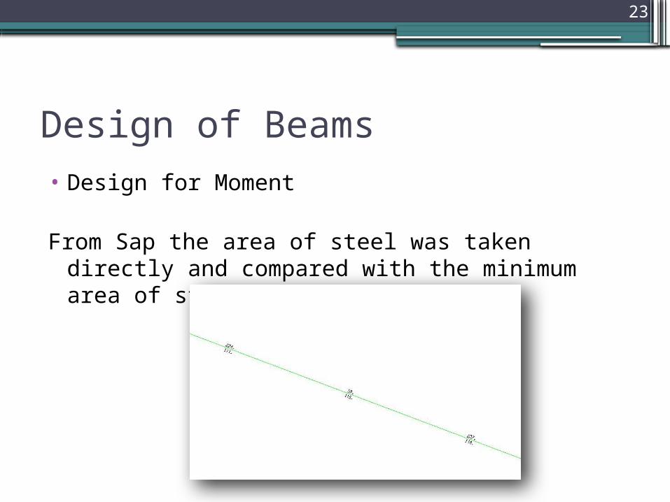
Design of Beams• Design for Moment
From Sap the area of steel was taken directly and compared with the minimum area of steel

24
Design of Beams• Design for Moment
25
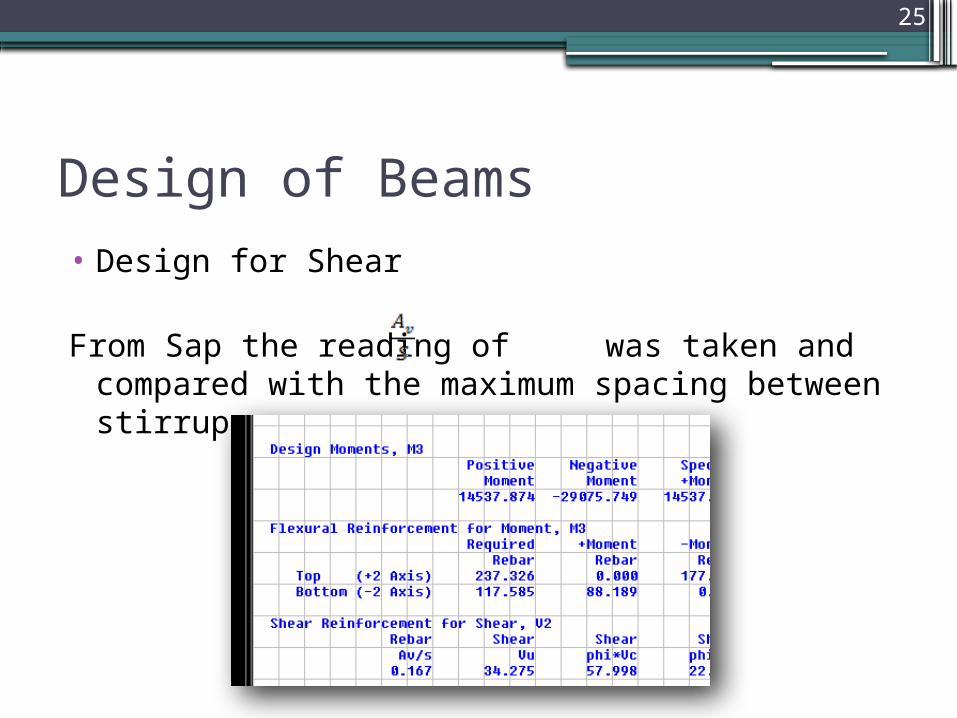
Design of Beams• Design for Shear
From Sap the reading of was taken and compared with the maximum spacing between stirrups.

26
Design of Beams• Design for Shear

27
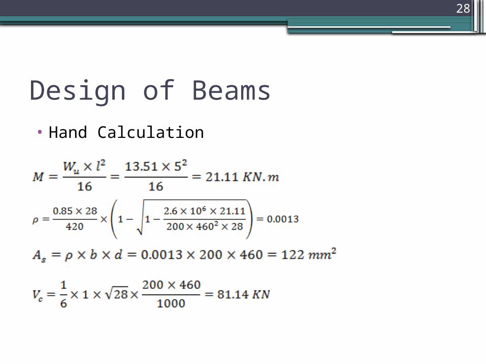
Design of Beams• Hand Calculation ??
This calculation aims to check the results of Sap, so it will perform to B1-type beams:
28
Design of Beams• Hand Calculation
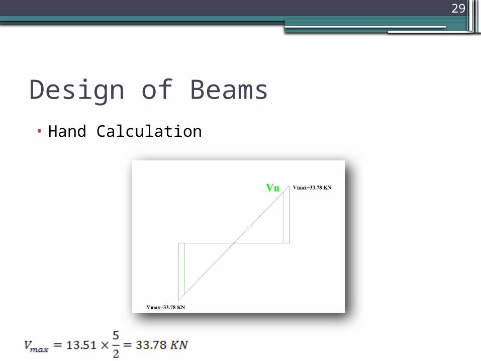
29
Design of Beams• Hand Calculation
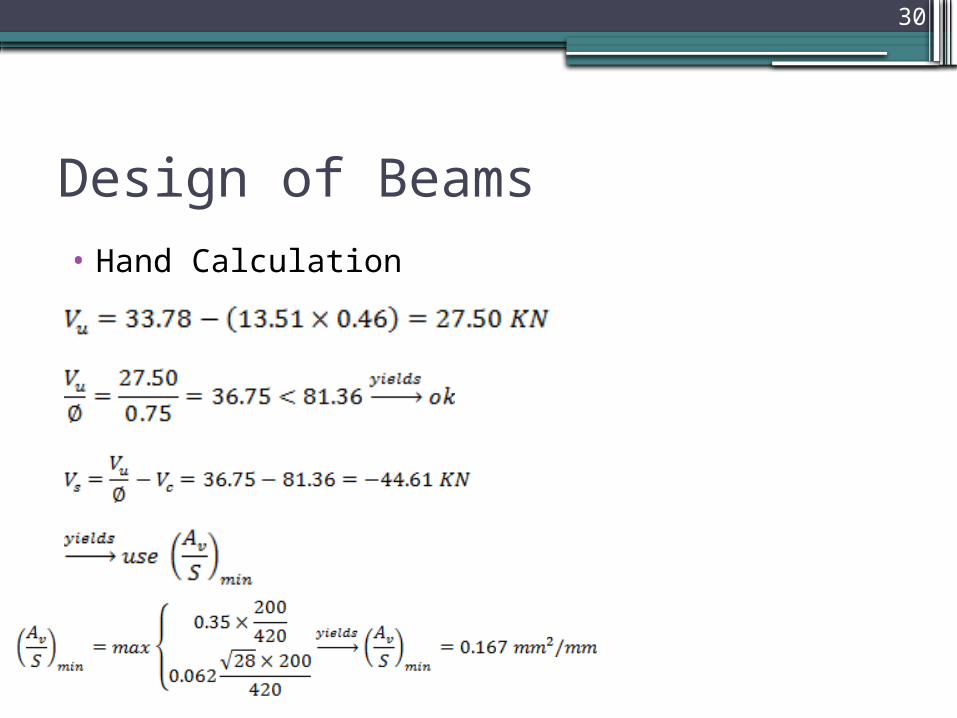
30
Design of Beams• Hand Calculation
31
Design of Beams• Hand Calculation
Compare this result with the result from sap; it’s noticeable that the two results are very close, so it’s fair to say that the Sap is accurate.
32
Chapter 2: Concrete Elements DesignDesign of Columns
33
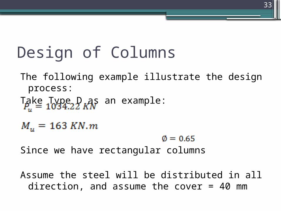
Design of ColumnsThe following example illustrate the design process:Take Type D as an example:
Since we have rectangular columns
Assume the steel will be distributed in all direction, and assume the cover = 40 mm

34
Design of Columns
The bending occurs about the strong axis which has larger moment of inertia.
35
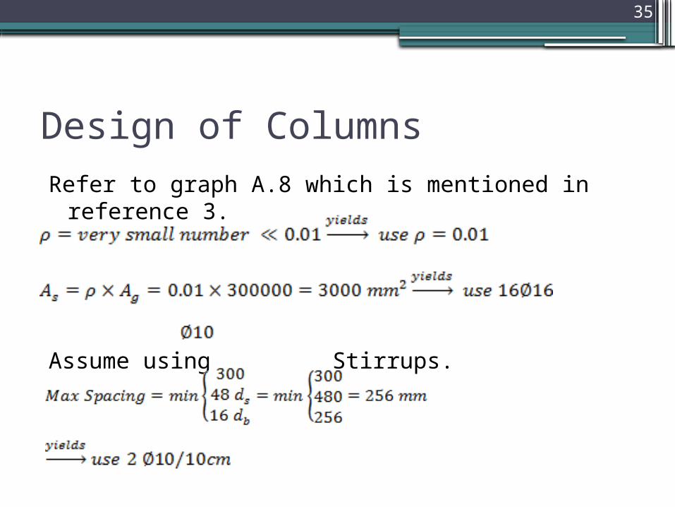
Design of ColumnsRefer to graph A.8 which is mentioned in reference 3.
Assume using Stirrups.

36
Chapter 2: Concrete Elements DesignDesign of Shear Wall
37
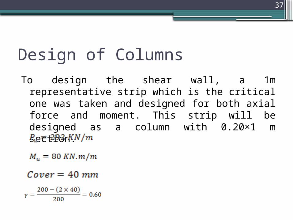
Design of ColumnsTo design the shear wall, a 1m representative strip which is the
critical one was taken and designed for both axial force and moment. This strip will be designed as a column with 0.20×1 m section.
38
Design of Columns
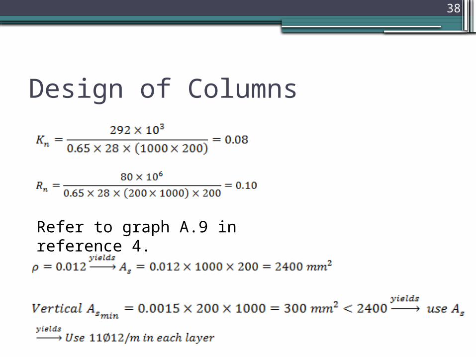
Refer to graph A.9 in reference 4.
39
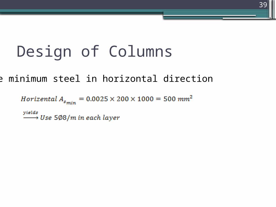
Design of Columns
Use minimum steel in horizontal direction
40
Chapter 2: Concrete Elements DesignDesign of Footings

41
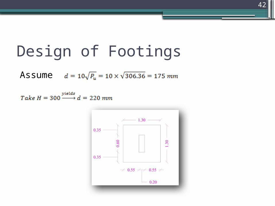
Design of FootingsThere are 3 types of footings single, combined and wall
footings, all of them was designed manually. The methodology of design for each type was shown below:
• Single footingTake column 33 which is the critical column of F2 type.
42
Design of FootingsAssume
43
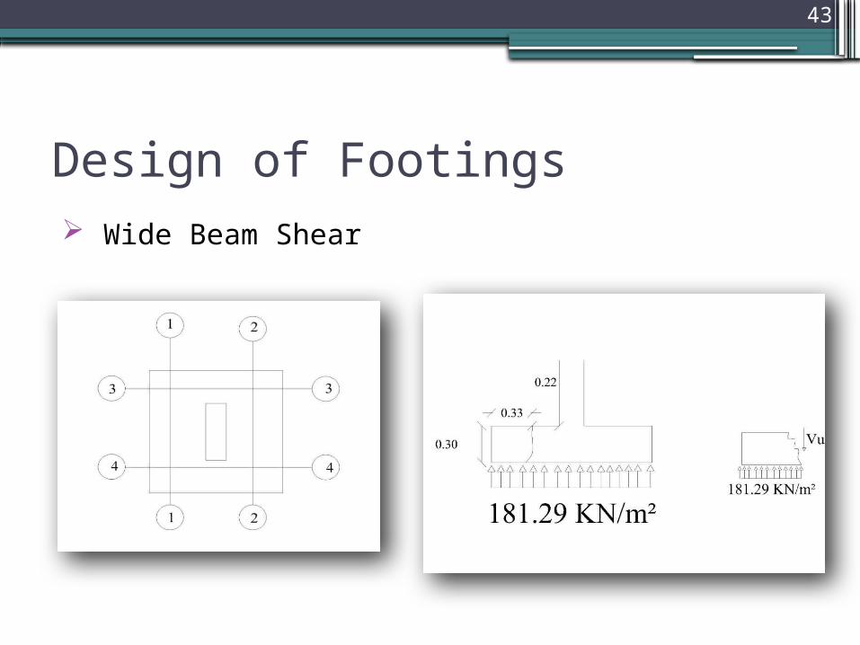
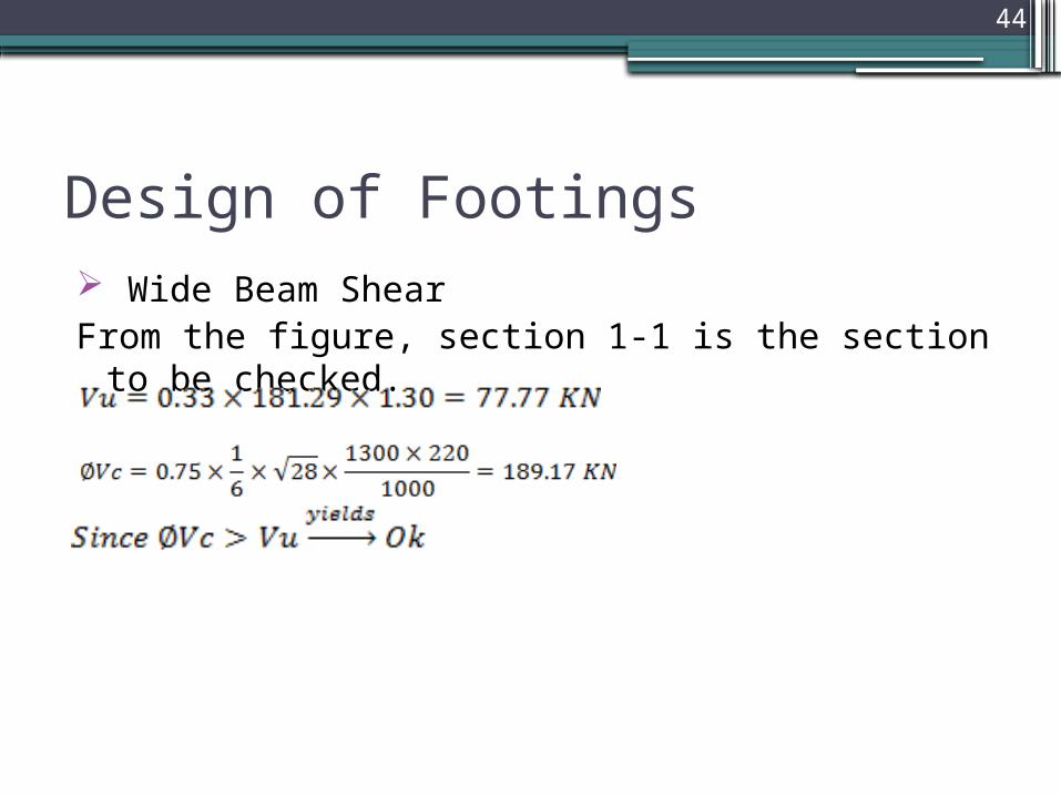
Design of Footings Wide Beam Shear
44
Design of Footings Wide Beam ShearFrom the figure, section 1-1 is the section to be checked.
45
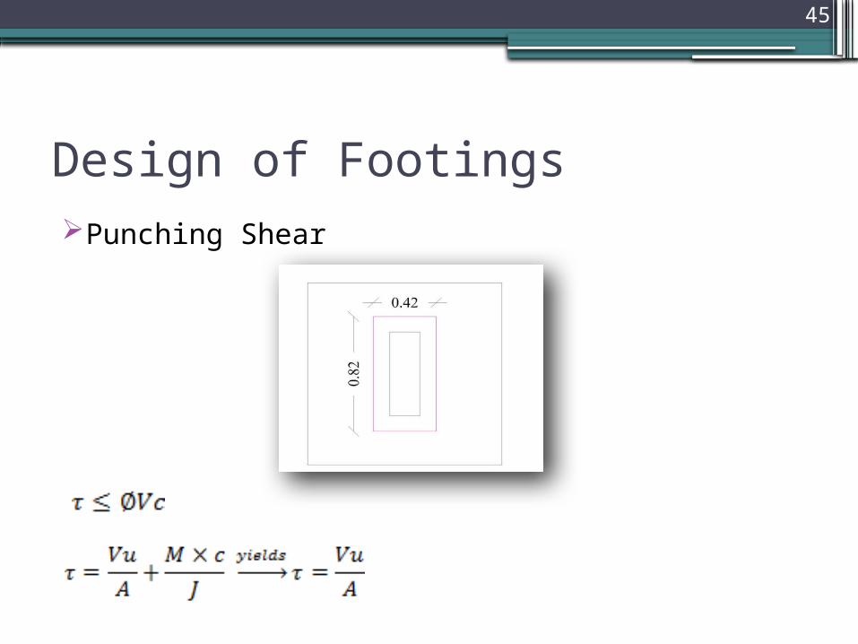
Design of FootingsPunching Shear
46
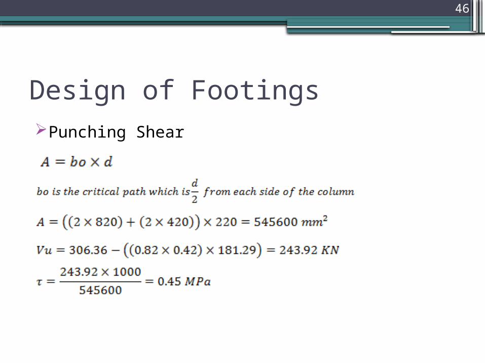
Design of FootingsPunching Shear
47
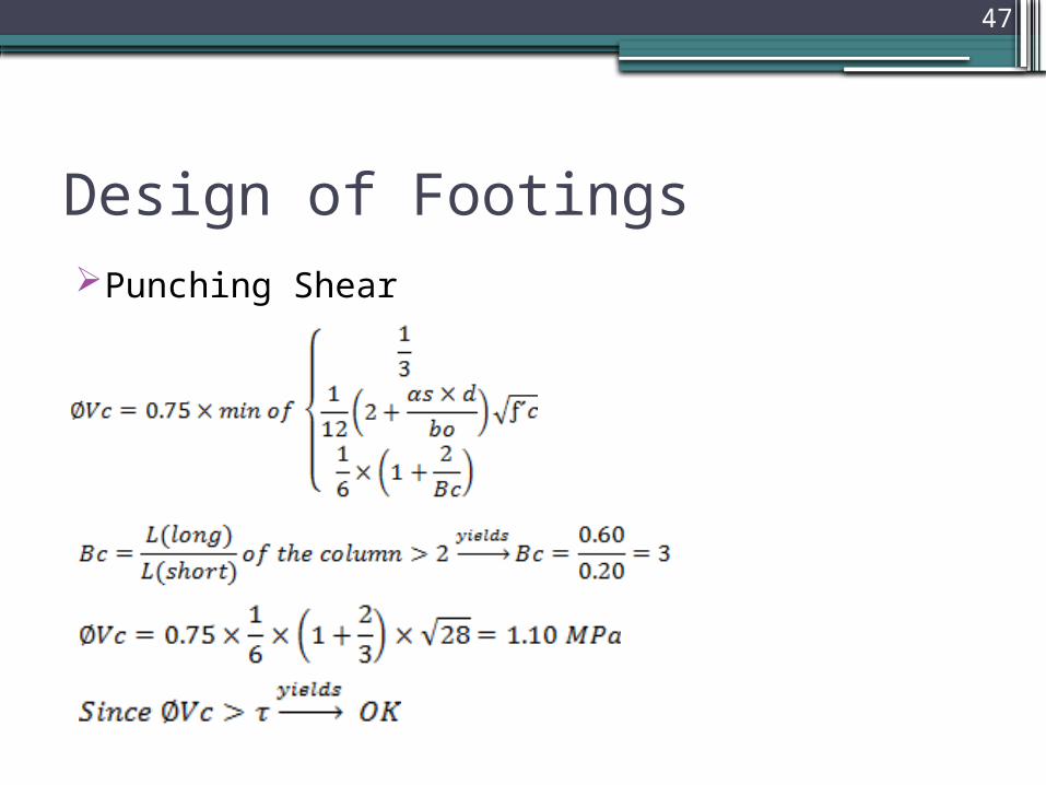
Design of FootingsPunching Shear

48
Design of FootingsReinforcement (N-S Direction).
Take a strip of 1 m wide and perform the calculation on it.

49
Design of FootingsReinforcement (N-S Direction).
50
Design of FootingsThe reinforcement of the E-W direction will be the same.
51
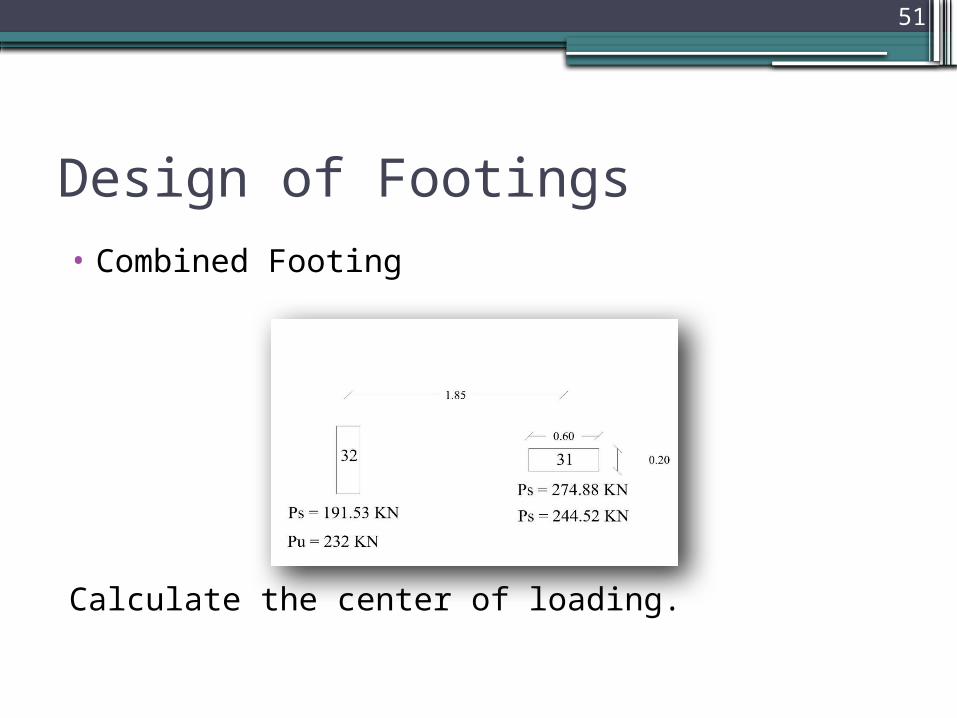
Design of Footings• Combined Footing
Calculate the center of loading.

52
Design of Footings• Combined Footing
53
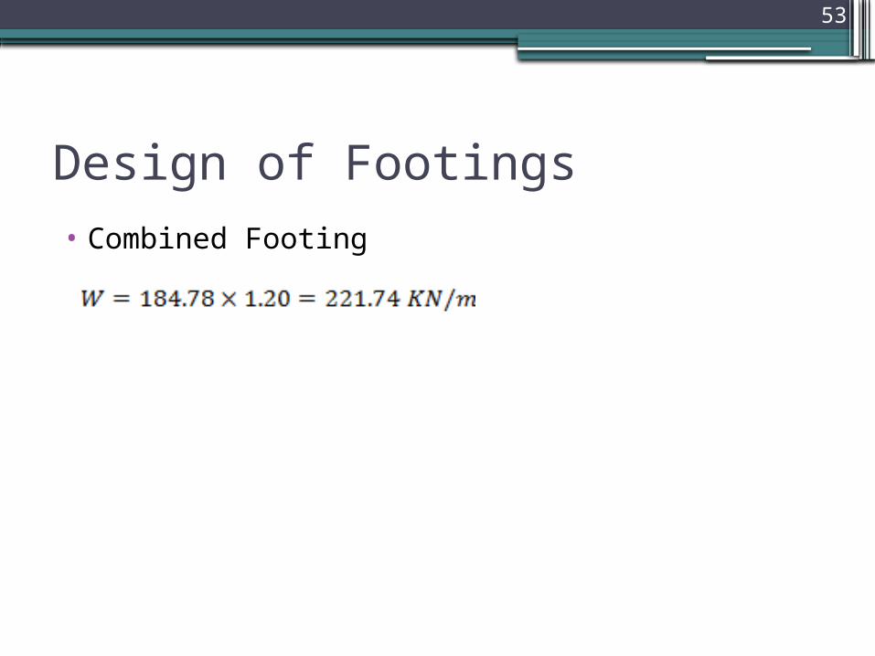
Design of Footings• Combined Footing

54
55
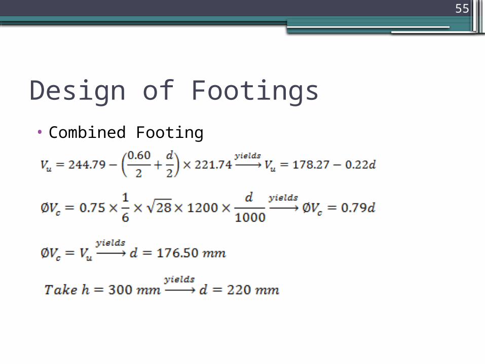
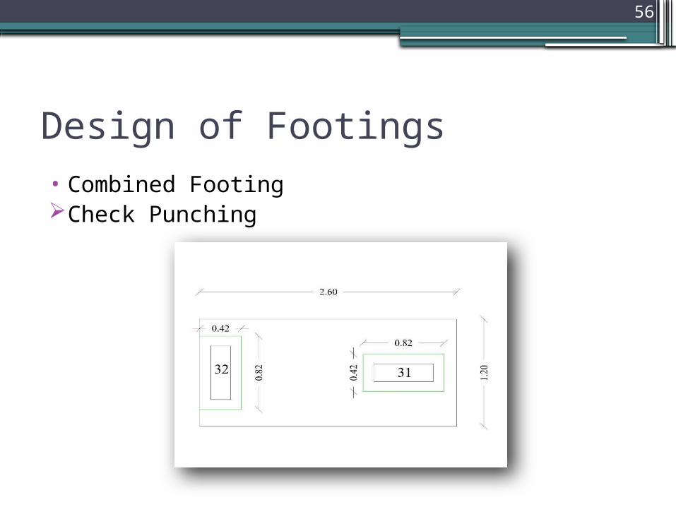
Design of Footings• Combined Footing
56
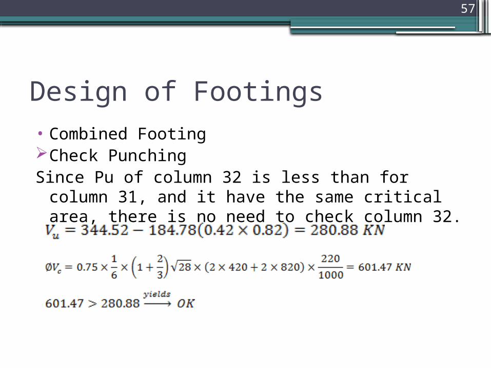
Design of Footings• Combined FootingCheck Punching
57
Design of Footings• Combined FootingCheck Punching Since Pu of column 32 is less than for column 31, and it have
the same critical area, there is no need to check column 32.
58
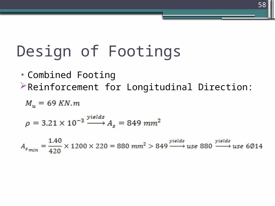
Design of Footings• Combined FootingReinforcement for Longitudinal Direction:

59
Design of Footings• Combined FootingReinforcement for Lateral Direction:

60
Design of Footings• Combined FootingReinforcement for Lateral Direction:
Zone 1 and zone 3 will designed for lateral moment, but zone 2 and zone 4 will designed for shrinkage only.
The design of zone 1 was shown below:

61
Design of Footings• Combined FootingReinforcement for Lateral Direction:
62
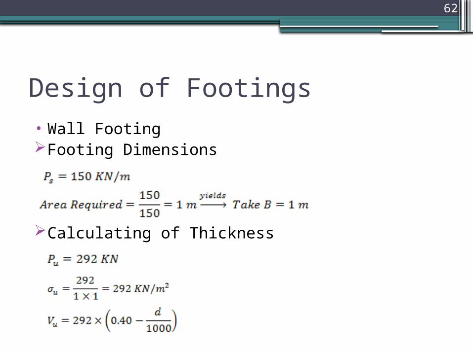
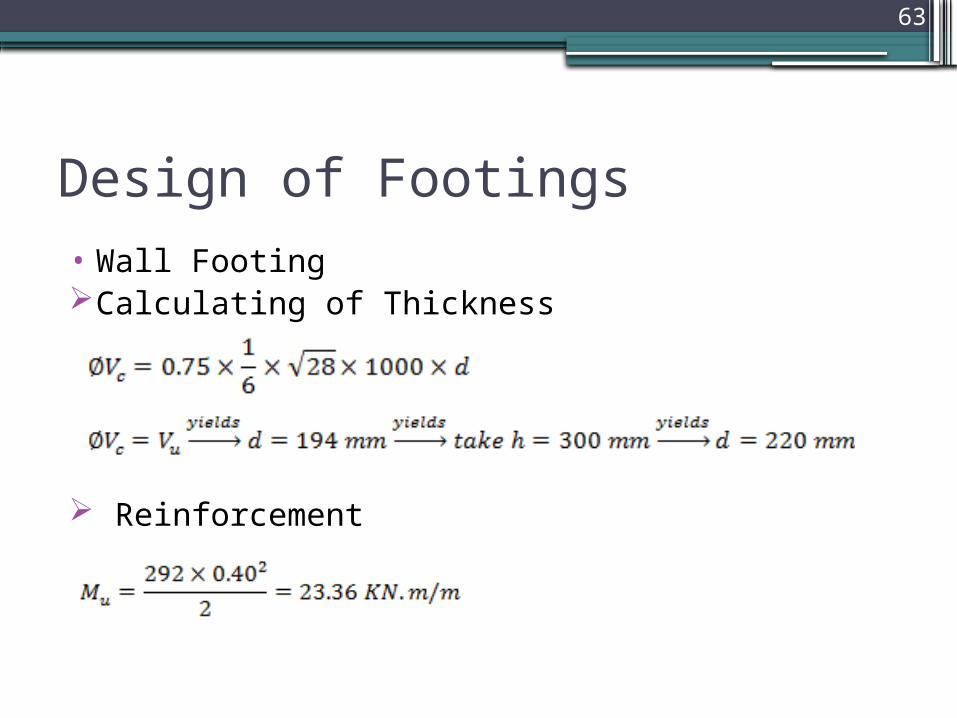
Design of Footings• Wall FootingFooting Dimensions
Calculating of Thickness
63
Design of Footings• Wall FootingCalculating of Thickness
Reinforcement

64
Design of Footings• Wall Footing Reinforcement
Use As minimum for longitudinal direction.
65
Chapter 3: Steel Structure Design
66
Design of Steel Structure• AssumptionsThe Material used in this project is steel A-36 which has the
following characteristics:- Fu = 400 Mpa.- Fy = 248 Mpa.
67
Design of Steel Structure• Assumptions
The loads resisted by the structure are:
- Live Load with a value of 1.20 KN/m².- Superimposed dead load with a value of 0.30 KN/m².- Wind Load with a value of 0.27 KN/m², the calculation of wind load will
be illustrated later.
68
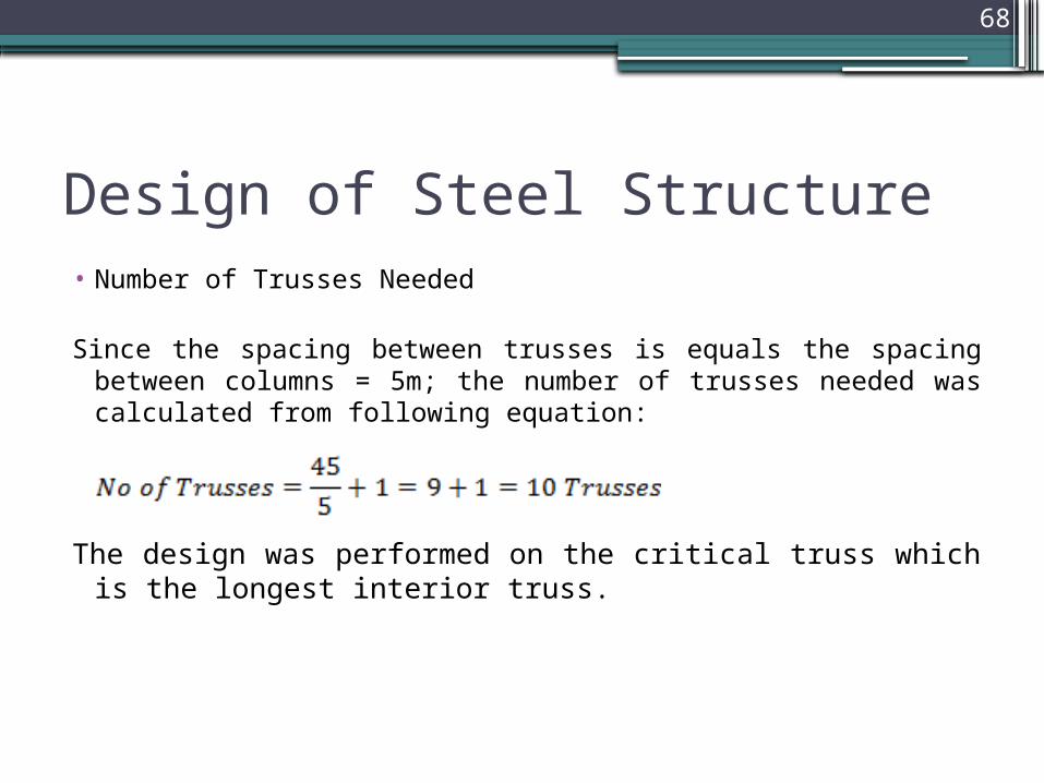
Design of Steel Structure• Number of Trusses Needed
Since the spacing between trusses is equals the spacing between columns = 5m; the number of trusses needed was calculated from following equation:
The design was performed on the critical truss which is the longest interior truss.
69
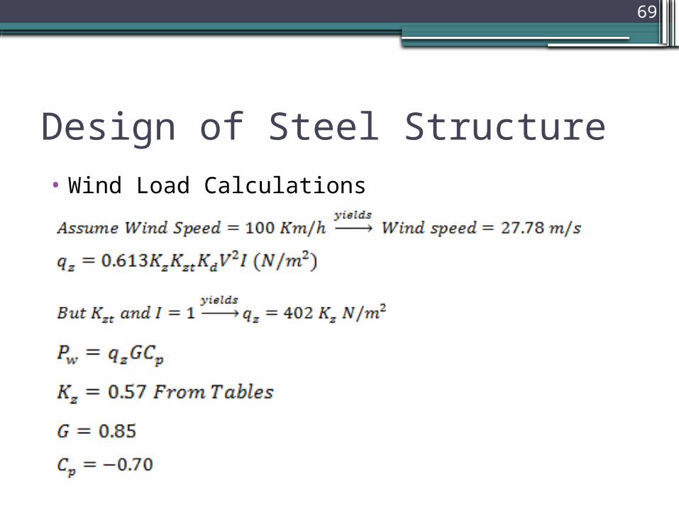
Design of Steel Structure• Wind Load Calculations

70
Design of Steel Structure• Wind Load Calculations
Since the minimum load is greater than the computed one, take the minimum as a design load.
71
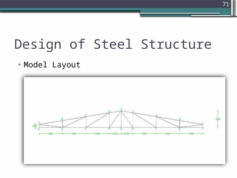
Design of Steel Structure• Model Layout
72
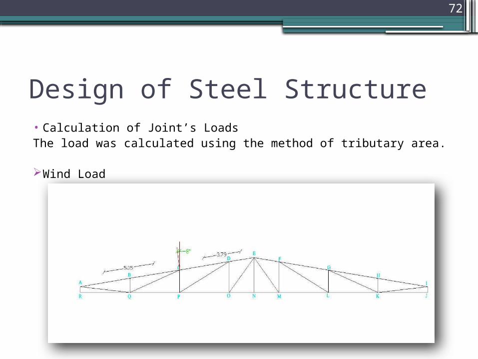
Design of Steel Structure• Calculation of Joint’s LoadsThe load was calculated using the method of tributary area.
Wind Load
73
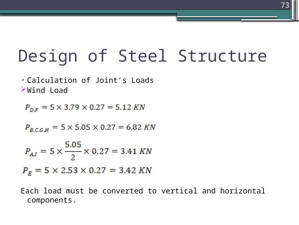
Design of Steel Structure• Calculation of Joint’s LoadsWind Load
Each load must be converted to vertical and horizontal components.
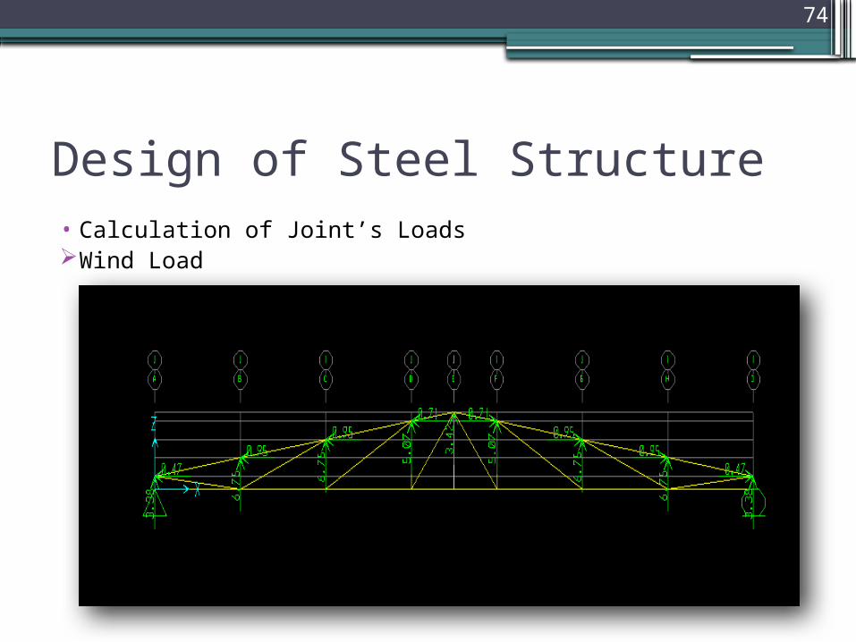
74
Design of Steel Structure• Calculation of Joint’s LoadsWind Load
75
Design of Steel Structure•Calculation of Joint’s Loads
And with the same way superimposed and live load were calculated.

76
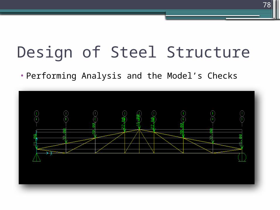
Design of Steel Structure• Performing Analysis and the Model’s Checks
After drawing 2-D model on SAP, importing the values of loads, defining load combinations and running the model, many checks should be done.
77
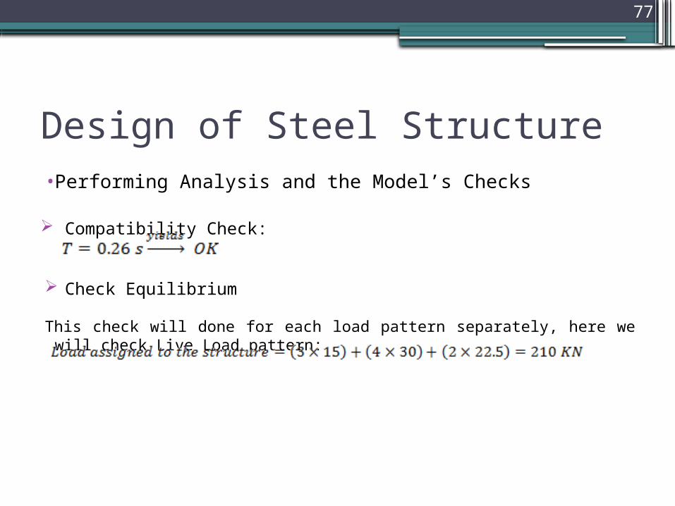
Design of Steel Structure• Performing Analysis and the Model’s Checks
Compatibility Check:
Check Equilibrium
This check will done for each load pattern separately, here we will check Live Load pattern:
78
Design of Steel Structure• Performing Analysis and the Model’s Checks

79
Design of Steel Structure• Performing Analysis and the Model’s Checks
Reactions due to live load.

80
Design of Steel Structure• Performing Analysis and the Model’s Checks
Stress-Strain Relationship

81
Design of Steel Structure• Performing Analysis and the Model’s Checks
Axial force in member MN.
82
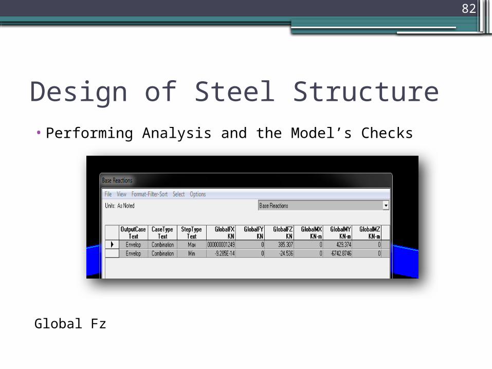
Design of Steel Structure• Performing Analysis and the Model’s Checks
Global Fz
83
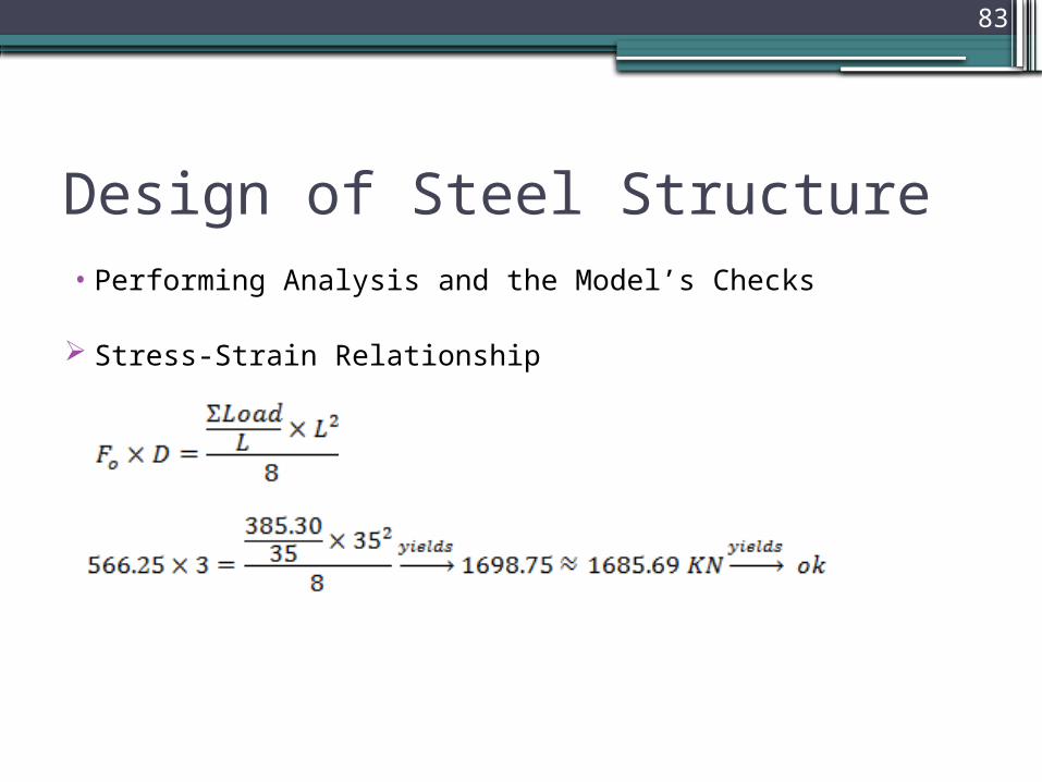
Design of Steel Structure• Performing Analysis and the Model’s Checks
Stress-Strain Relationship
84
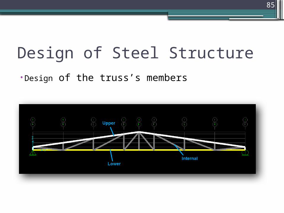
Design of Steel Structure• Design of the truss’s members
The design was performed using SAP with selecting Pipe-sections. The output results are shown in table 12 page 36.
Its clear that there are 3 different pipe sections due to defining design groups. The upper members will have the same section, also the internal members and lower members do.
85
Design of Steel Structure• Design of the truss’s members
86
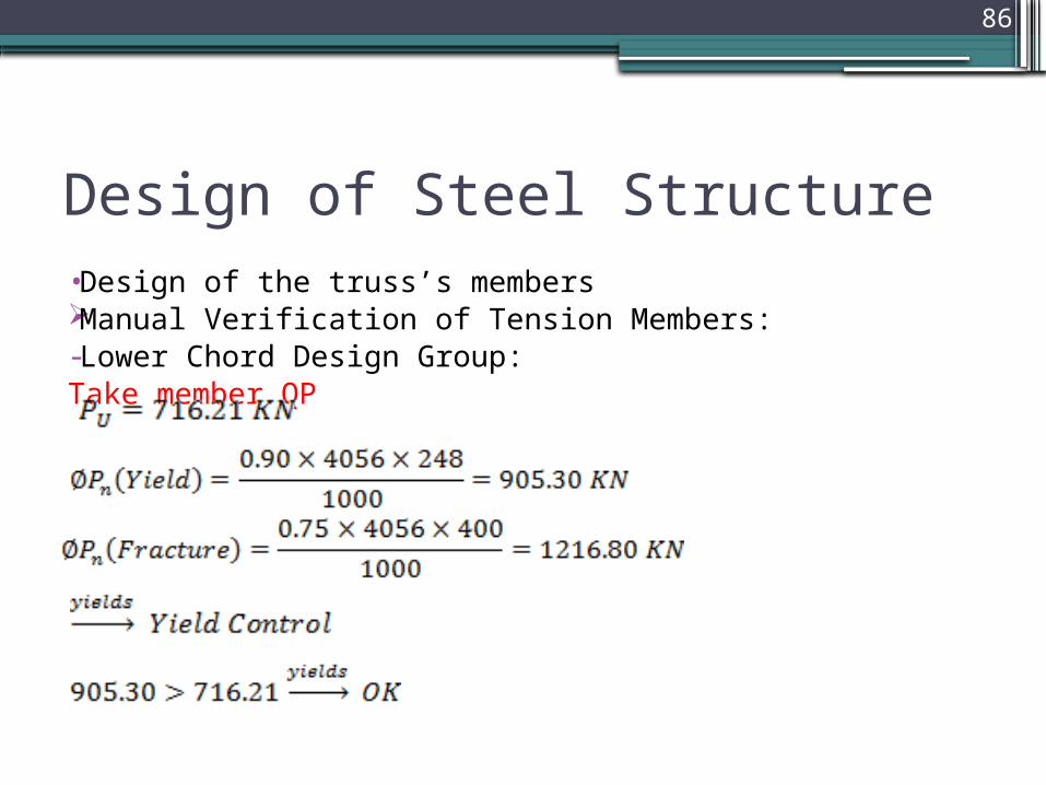
Design of Steel Structure• Design of the truss’s members Manual Verification of Tension Members:- Lower Chord Design Group:Take member QP

87
Design of Steel Structure• Design of the truss’s members Manual Verification of Tension Members:- Internal Chord Design GroupTake member AQ
88
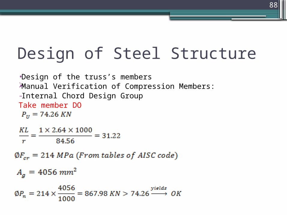
Design of Steel Structure• Design of the truss’s members Manual Verification of Compression Members:- Internal Chord Design GroupTake member DO

89
Design of Steel Structure• Design of the truss’s members Manual Verification of Compression Members:- Internal Chord Design GroupTake member GK

90
Design of Steel Structure• Design of the truss’s members Manual Verification of Compression Members:- Upper Chord Design GroupTake member CD
91
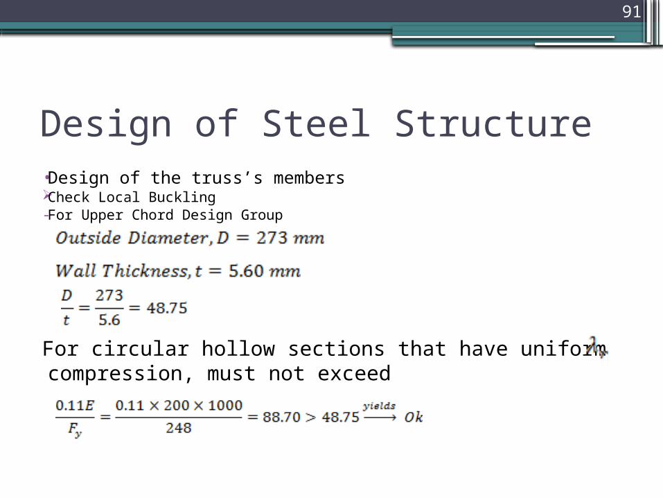
Design of Steel Structure• Design of the truss’s members Check Local Buckling- For Upper Chord Design Group
For circular hollow sections that have uniform compression, must not exceed

92
Design of Steel Structure• Design of the truss’s members Check Local Buckling- For Internal Chord Design Group
93
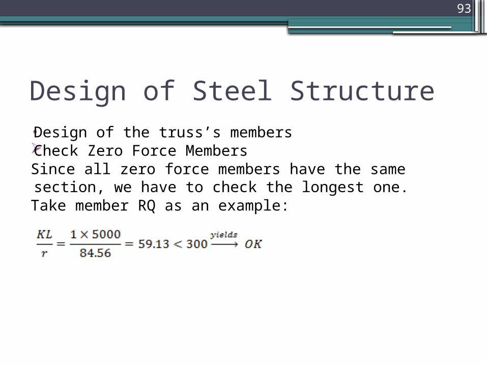
Design of Steel Structure• Design of the truss’s membersCheck Zero Force MembersSince all zero force members have the same section, we have to
check the longest one.Take member RQ as an example:
94
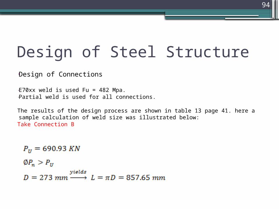
Design of Steel Structure• Design of Connections
- E70xx weld is used Fu = 482 Mpa.- Partial weld is used for all connections.
The results of the design process are shown in table 13 page 41. here a sample calculation of weld size was illustrated below:
Take Connection B
95
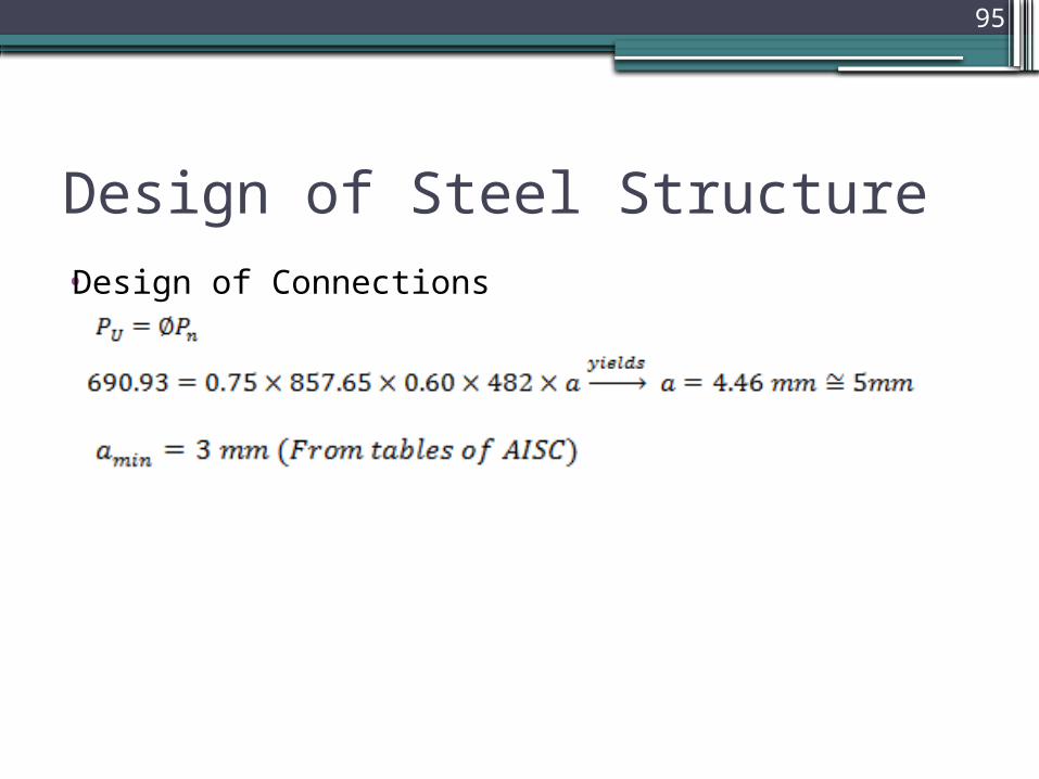
Design of Steel Structure• Design of Connections
96
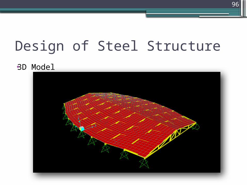
Design of Steel Structure• 3D Model

97


![Semantic Enrichments in Text Supervised Classification ...ACTI 14.2]-Albitar... · Wikipedia (Wang and Domeniconi, 2008) or domain specific ontologies like UMLS for the biomedical](https://img.pdfslide.net/doc/110x75/5b2e80a57f8b9a91438bfe6f/semantic-enrichments-in-text-supervised-classification-acti-142-albitar.jpg)


