Embed Size (px)
Citation preview
Tunable RF and Microwave Filters(Invited Paper)
Xiaoguang ”Leo” LiuDepartment of Eletrical and Computer EngineeringUniversity of California, Davis, CA, USA, 95616
Email: [email protected]
Abstract—Tunable filters at RF and microwave frequencies can po-
tentially place an important role in the implementation offuture reconfigurable wireless systems.This paper provides ageneral review of several competing technologies in realizinghigh performance tunable filters with a slight focus on recentprogress in the design and implementation of evanescent-modecavity based filters with both frequency and bandwidth tuningcapabilities.
Index Terms—microwave filter, tunable filter
I. INTRODUCTION
The last decade has seen tremendous progress in the devel-opment of wireless communication technologies. Ubiquitousconnectivity and increased functionality are the main driv-ing forces of ever increasing complexity in modern wirelesscommunication systems. For example, with the advent of 4Gnetworks, cell phones are expected to be compatible withseveral standards (2G to 4G) covering 40+ frequency bandsfrom 700 MHz to 2, 700 MHz [1]. Such complexity coupledwith stringent low-cost and low-power requirements imposeunique challenges to the RF system designers.
The well-known Software Defined Radio (SDR) [2] andCognitive Radio (CR) [3] concepts have been proposed totackle these challenges. While a number of different SDR andCR architectures have been proposed, in general, SDR or CRsystems should be able to sense the frequency spectrum andalter their operating parameters depending on the availablebands. This typically requires the ability to reconfigure theradio’s hardware and particularly the RF front-end, over a widefrequency range.
The implementation of a fully reconfigurable RF front-endrelies heavily on the availability of reconfigurable RF com-ponents. Whereas active circuits are relatively easier to tune,making high-quality low-power widely tunable passive com-ponents in mobile form factors has proven to be particularlychallenging. For example, RF filters are common but criticalcomponents in the RF front-end. Traditional technologies formaking tunable RF filters, such as ferrimagnetic resonators,micromechanical resonators, cavity resonators, varactor loadedplanar resonators, offer excellent performance in few importantareas, but fail to satisfy all necessary requirements and desires.
This paper provides a general review of recent progress inthe design and implementation of tunable RF and microwavefilters.
II. DESIGN CONSIDERATIONS
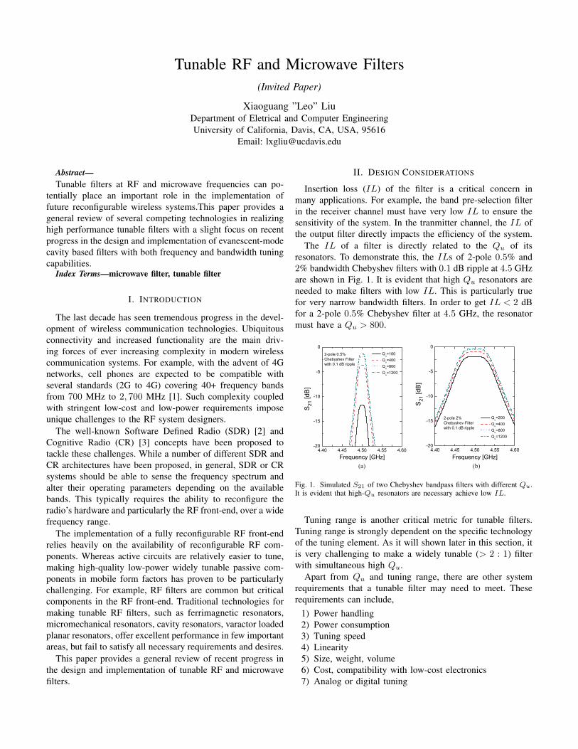
Insertion loss (IL) of the filter is a critical concern inmany applications. For example, the band pre-selection filterin the receiver channel must have very low IL to ensure thesensitivity of the system. In the tranmitter channel, the IL ofthe output filter directly impacts the efficiency of the system.
The IL of a filter is directly related to the Qu of itsresonators. To demonstrate this, the ILs of 2-pole 0.5% and2% bandwidth Chebyshev filters with 0.1 dB ripple at 4.5 GHzare shown in Fig. 1. It is evident that high Qu resonators areneeded to make filters with low IL. This is particularly truefor very narrow bandwidth filters. In order to get IL < 2 dBfor a 2-pole 0.5% Chebyshev filter at 4.5 GHz, the resonatormust have a Qu > 800.
S21
[dB
]
S21
[dB
]
(a) (b)
Fig. 1. Simulated S21 of two Chebyshev bandpass filters with different Qu.It is evident that high-Qu resonators are necessary achieve low IL.
Tuning range is another critical metric for tunable filters.Tuning range is strongly dependent on the specific technologyof the tuning element. As it will shown later in this section, itis very challenging to make a widely tunable (> 2 : 1) filterwith simultaneous high Qu.
Apart from Qu and tuning range, there are other systemrequirements that a tunable filter may need to meet. Theserequirements can include,
1) Power handling2) Power consumption3) Tuning speed4) Linearity5) Size, weight, volume6) Cost, compatibility with low-cost electronics7) Analog or digital tuning
8) Immunity to vibration, shock, temperature, noise on tun-ing voltage
III. A REVIEW OF FREQUENCY TUNING TECHNOLOGIES
A. Ferrimagnetic Tunable Filters
Today, the highest performance (in terms of tunability andloss) tunable filters are based on ferrimagnetic resonators, suchas a yttrium-iron-garnite (YIG) crystal. YIG tunable filtersfind wide applications in measurement instruments and basestations for cellular networks. The resonant frequency of aYIG resonator can be tuned higher by increasing the externalmagnetic field. YIG tunable filters offer multi-octave tuningrange (2 − 18 GHz) and very high Qu (2000 − 5000 at2 − 10 GHz). One disadvantage of the YIG filters is theirlarge power consumption (0.75 − 3 W) used to generate theexternal magnetic field and to maintain a constant temperature.It is therefore very difficult to integrate YIG filters in portablewireless devices where battery life is a critical concern. Inaddition, there is a minimum tuned frequency when theexternal magnetic field is equal to the demagnetizing fieldstrength. This minimum frequency is usually between 1 GHzand 2 GHz [4].
B. Planar Tunable Filters
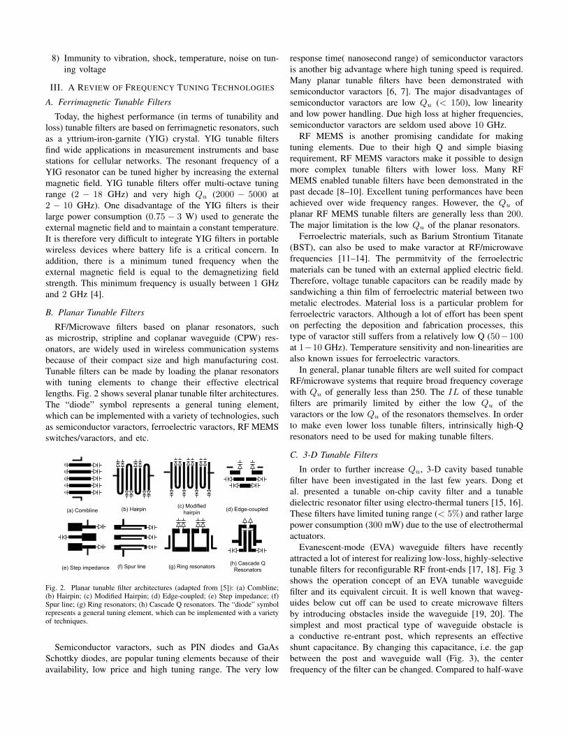
RF/Microwave filters based on planar resonators, suchas microstrip, stripline and coplanar waveguide (CPW) res-onators, are widely used in wireless communication systemsbecause of their compact size and high manufacturing cost.Tunable filters can be made by loading the planar resonatorswith tuning elements to change their effective electricallengths. Fig. 2 shows several planar tunable filter architectures.The “diode” symbol represents a general tuning element,which can be implemented with a variety of technologies, suchas semiconductor varactors, ferroelectric varactors, RF MEMSswitches/varactors, and etc.
(b) Hairpin (c) Modifiedhairpin
(e) Step impedance (g) Ring resonators (h) Cascade QResonators
(a) Combline (d) Edge-coupled
(f) Spur line
Fig. 2. Planar tunable filter architectures (adapted from [5]): (a) Combline;(b) Hairpin; (c) Modified Hairpin; (d) Edge-coupled; (e) Step impedance; (f)Spur line; (g) Ring resonators; (h) Cascade Q resonators. The “diode” symbolrepresents a general tuning element, which can be implemented with a varietyof techniques.
Semiconductor varactors, such as PIN diodes and GaAsSchottky diodes, are popular tuning elements because of theiravailability, low price and high tuning range. The very low
response time( nanosecond range) of semiconductor varactorsis another big advantage where high tuning speed is required.Many planar tunable filters have been demonstrated withsemiconductor varactors [6, 7]. The major disadvantages ofsemiconductor varactors are low Qu (< 150), low linearityand low power handling. Due high loss at higher frequencies,semiconductor varactors are seldom used above 10 GHz.
RF MEMS is another promising candidate for makingtuning elements. Due to their high Q and simple biasingrequirement, RF MEMS varactors make it possible to designmore complex tunable filters with lower loss. Many RFMEMS enabled tunable filters have been demonstrated in thepast decade [8–10]. Excellent tuning performances have beenachieved over wide frequency ranges. However, the Qu ofplanar RF MEMS tunable filters are generally less than 200.The major limitation is the low Qu of the planar resonators.
Ferroelectric materials, such as Barium Strontium Titanate(BST), can also be used to make varactor at RF/microwavefrequencies [11–14]. The permmitvity of the ferroelectricmaterials can be tuned with an external applied electric field.Therefore, voltage tunable capacitors can be readily made bysandwiching a thin film of ferroelectric material between twometalic electrodes. Material loss is a particular problem forferroelectric varactors. Although a lot of effort has been spenton perfecting the deposition and fabrication processes, thistype of varactor still suffers from a relatively low Q (50−100at 1−10 GHz). Temperature sensitivity and non-linearities arealso known issues for ferroelectric varactors.
In general, planar tunable filters are well suited for compactRF/microwave systems that require broad frequency coveragewith Qu of generally less than 250. The IL of these tunablefilters are primarily limited by either the low Qu of thevaractors or the low Qu of the resonators themselves. In orderto make even lower loss tunable filters, intrinsically high-Qresonators need to be used for making tunable filters.
C. 3-D Tunable Filters
In order to further increase Qu, 3-D cavity based tunablefilter have been investigated in the last few years. Dong etal. presented a tunable on-chip cavity filter and a tunabledielectric resonator filter using electro-thermal tuners [15, 16].These filters have limited tuning range (< 5%) and rather largepower consumption (300 mW) due to the use of electrothermalactuators.
Evanescent-mode (EVA) waveguide filters have recentlyattracted a lot of interest for realizing low-loss, highly-selectivetunable filters for reconfigurable RF front-ends [17, 18]. Fig 3shows the operation concept of an EVA tunable waveguidefilter and its equivalent circuit. It is well known that waveg-uides below cut off can be used to create microwave filtersby introducing obstacles inside the waveguide [19, 20]. Thesimplest and most practical type of waveguide obstacle isa conductive re-entrant post, which represents an effectiveshunt capacitance. By changing this capacitance, i.e. the gapbetween the post and waveguide wall (Fig. 3), the centerfrequency of the filter can be changed. Compared to half-wave
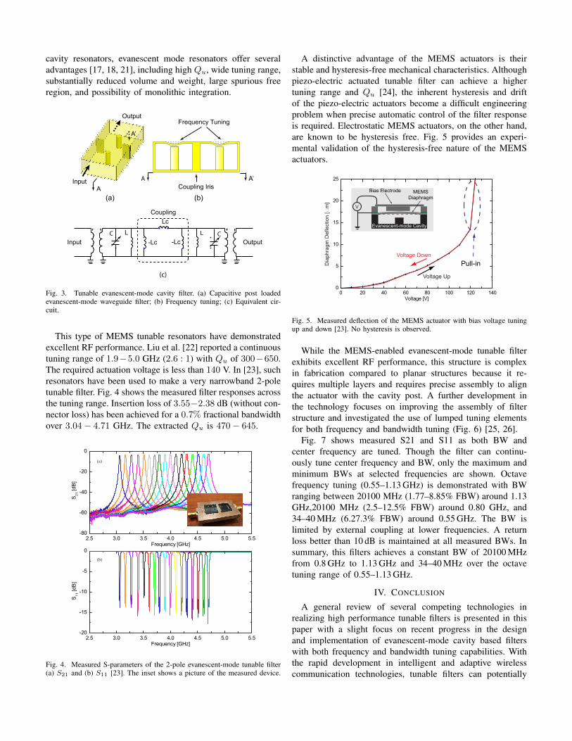
cavity resonators, evanescent mode resonators offer severaladvantages [17, 18, 21], including high Qu, wide tuning range,substantially reduced volume and weight, large spurious freeregion, and possibility of monolithic integration.
L
Lc
-Lc-Lc
Frequency Tuning
A
A’
A A’Coupling Iris
Input Output
Output
Input
L
Coupling
(a)
(c)
(b)
C C
Fig. 3. Tunable evanescent-mode cavity filter. (a) Capacitive post loadedevanescent-mode waveguide filter; (b) Frequency tuning; (c) Equivalent cir-cuit.
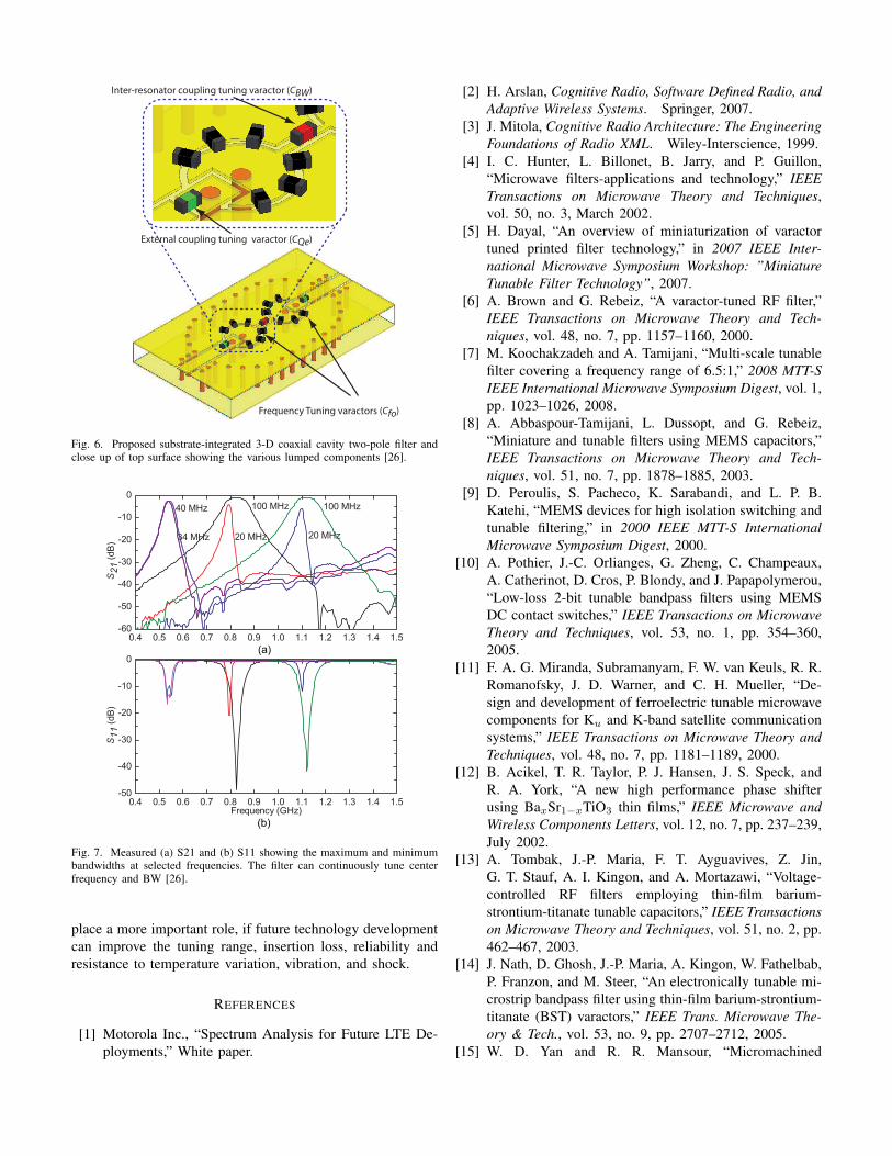
This type of MEMS tunable resonators have demonstratedexcellent RF performance. Liu et al. [22] reported a continuoustuning range of 1.9−5.0 GHz (2.6 : 1) with Qu of 300−650.The required actuation voltage is less than 140 V. In [23], suchresonators have been used to make a very narrowband 2-poletunable filter. Fig. 4 shows the measured filter responses acrossthe tuning range. Insertion loss of 3.55−2.38 dB (without con-nector loss) has been achieved for a 0.7% fractional bandwidthover 3.04− 4.71 GHz. The extracted Qu is 470− 645.
(a)
(b)
Fig. 4. Measured S-parameters of the 2-pole evanescent-mode tunable filter(a) S21 and (b) S11 [23]. The inset shows a picture of the measured device.
A distinctive advantage of the MEMS actuators is theirstable and hysteresis-free mechanical characteristics. Althoughpiezo-electric actuated tunable filter can achieve a highertuning range and Qu [24], the inherent hysteresis and driftof the piezo-electric actuators become a difficult engineeringproblem when precise automatic control of the filter responseis required. Electrostatic MEMS actuators, on the other hand,are known to be hysteresis free. Fig. 5 provides an experi-mental validation of the hysteresis-free nature of the MEMSactuators.
Dia
phra
gm D
efle
ctio
n [m
m]
Bias Electrode
Evanescent-mode Cavity
MEMSDiaphragm
V
Pull-in
Voltage Up
Voltage Down
Fig. 5. Measured deflection of the MEMS actuator with bias voltage tuningup and down [23]. No hysteresis is observed.
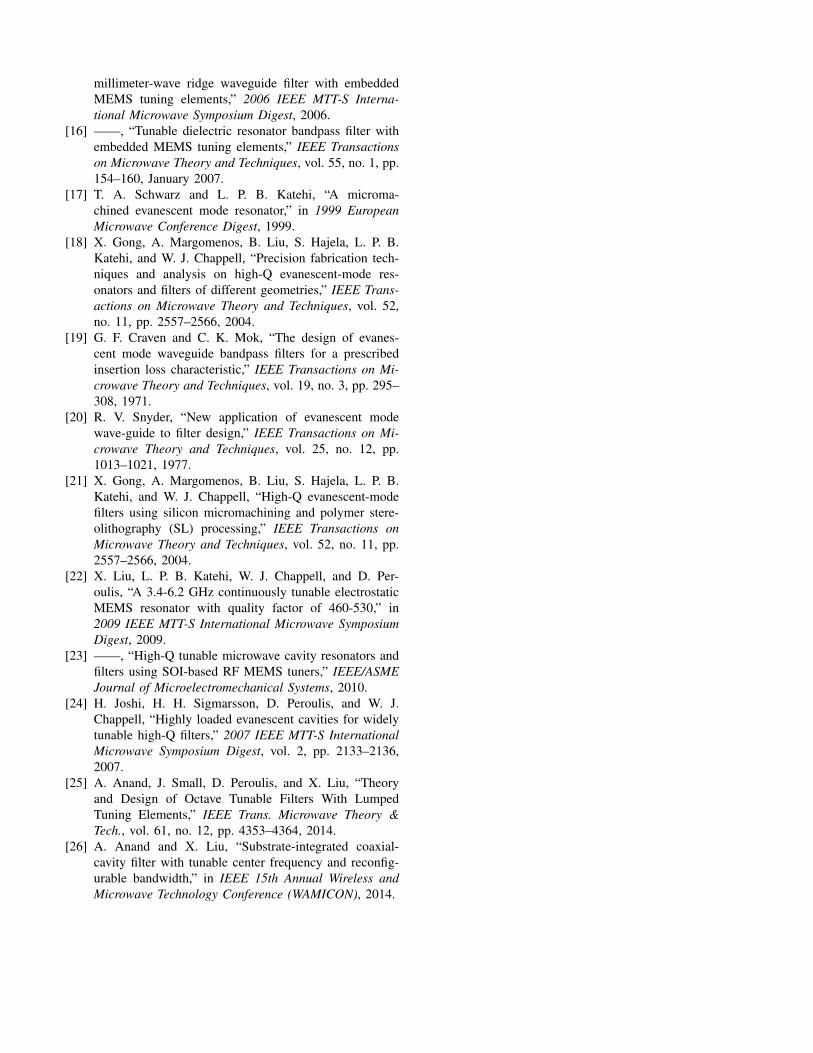
While the MEMS-enabled evanescent-mode tunable filterexhibits excellent RF performance, this structure is complexin fabrication compared to planar structures because it re-quires multiple layers and requires precise assembly to alignthe actuator with the cavity post. A further development inthe technology focuses on improving the assembly of filterstructure and investigated the use of lumped tuning elementsfor both frequency and bandwidth tuning (Fig. 6) [25, 26].
Fig. 7 shows measured S21 and S11 as both BW andcenter frequency are tuned. Though the filter can continu-ously tune center frequency and BW, only the maximum andminimum BWs at selected frequencies are shown. Octavefrequency tuning (0.55–1.13 GHz) is demonstrated with BWranging between 20100 MHz (1.77–8.85% FBW) around 1.13GHz,20100 MHz (2.5–12.5% FBW) around 0.80 GHz, and34–40 MHz (6.27.3% FBW) around 0.55 GHz. The BW islimited by external coupling at lower frequencies. A returnloss better than 10 dB is maintained at all measured BWs. Insummary, this filters achieves a constant BW of 20100 MHzfrom 0.8 GHz to 1.13 GHz and 34–40 MHz over the octavetuning range of 0.55–1.13 GHz.
IV. CONCLUSION
A general review of several competing technologies inrealizing high performance tunable filters is presented in thispaper with a slight focus on recent progress in the designand implementation of evanescent-mode cavity based filterswith both frequency and bandwidth tuning capabilities. Withthe rapid development in intelligent and adaptive wirelesscommunication technologies, tunable filters can potentially
Inter-resonator coupling tuning varactor (CBW)
External coupling tuning varactor (CQe)
Frequency Tuning varactors (Cfo)
Fig. 6. Proposed substrate-integrated 3-D coaxial cavity two-pole filter andclose up of top surface showing the various lumped components [26].
(a)
(b)
Fig. 7. Measured (a) S21 and (b) S11 showing the maximum and minimumbandwidths at selected frequencies. The filter can continuously tune centerfrequency and BW [26].
place a more important role, if future technology developmentcan improve the tuning range, insertion loss, reliability andresistance to temperature variation, vibration, and shock.
REFERENCES
[1] Motorola Inc., “Spectrum Analysis for Future LTE De-ployments,” White paper.
[2] H. Arslan, Cognitive Radio, Software Defined Radio, andAdaptive Wireless Systems. Springer, 2007.
[3] J. Mitola, Cognitive Radio Architecture: The EngineeringFoundations of Radio XML. Wiley-Interscience, 1999.
[4] I. C. Hunter, L. Billonet, B. Jarry, and P. Guillon,“Microwave filters-applications and technology,” IEEETransactions on Microwave Theory and Techniques,vol. 50, no. 3, March 2002.
[5] H. Dayal, “An overview of miniaturization of varactortuned printed filter technology,” in 2007 IEEE Inter-national Microwave Symposium Workshop: ”MiniatureTunable Filter Technology”, 2007.
[6] A. Brown and G. Rebeiz, “A varactor-tuned RF filter,”IEEE Transactions on Microwave Theory and Tech-niques, vol. 48, no. 7, pp. 1157–1160, 2000.
[7] M. Koochakzadeh and A. Tamijani, “Multi-scale tunablefilter covering a frequency range of 6.5:1,” 2008 MTT-SIEEE International Microwave Symposium Digest, vol. 1,pp. 1023–1026, 2008.
[8] A. Abbaspour-Tamijani, L. Dussopt, and G. Rebeiz,“Miniature and tunable filters using MEMS capacitors,”IEEE Transactions on Microwave Theory and Tech-niques, vol. 51, no. 7, pp. 1878–1885, 2003.
[9] D. Peroulis, S. Pacheco, K. Sarabandi, and L. P. B.Katehi, “MEMS devices for high isolation switching andtunable filtering,” in 2000 IEEE MTT-S InternationalMicrowave Symposium Digest, 2000.
[10] A. Pothier, J.-C. Orlianges, G. Zheng, C. Champeaux,A. Catherinot, D. Cros, P. Blondy, and J. Papapolymerou,“Low-loss 2-bit tunable bandpass filters using MEMSDC contact switches,” IEEE Transactions on MicrowaveTheory and Techniques, vol. 53, no. 1, pp. 354–360,2005.
[11] F. A. G. Miranda, Subramanyam, F. W. van Keuls, R. R.Romanofsky, J. D. Warner, and C. H. Mueller, “De-sign and development of ferroelectric tunable microwavecomponents for Ku and K-band satellite communicationsystems,” IEEE Transactions on Microwave Theory andTechniques, vol. 48, no. 7, pp. 1181–1189, 2000.
[12] B. Acikel, T. R. Taylor, P. J. Hansen, J. S. Speck, andR. A. York, “A new high performance phase shifterusing BaxSr1−xTiO3 thin films,” IEEE Microwave andWireless Components Letters, vol. 12, no. 7, pp. 237–239,July 2002.
[13] A. Tombak, J.-P. Maria, F. T. Ayguavives, Z. Jin,G. T. Stauf, A. I. Kingon, and A. Mortazawi, “Voltage-controlled RF filters employing thin-film barium-strontium-titanate tunable capacitors,” IEEE Transactionson Microwave Theory and Techniques, vol. 51, no. 2, pp.462–467, 2003.
[14] J. Nath, D. Ghosh, J.-P. Maria, A. Kingon, W. Fathelbab,P. Franzon, and M. Steer, “An electronically tunable mi-crostrip bandpass filter using thin-film barium-strontium-titanate (BST) varactors,” IEEE Trans. Microwave The-ory & Tech., vol. 53, no. 9, pp. 2707–2712, 2005.
[15] W. D. Yan and R. R. Mansour, “Micromachined
millimeter-wave ridge waveguide filter with embeddedMEMS tuning elements,” 2006 IEEE MTT-S Interna-tional Microwave Symposium Digest, 2006.
[16] ——, “Tunable dielectric resonator bandpass filter withembedded MEMS tuning elements,” IEEE Transactionson Microwave Theory and Techniques, vol. 55, no. 1, pp.154–160, January 2007.
[17] T. A. Schwarz and L. P. B. Katehi, “A microma-chined evanescent mode resonator,” in 1999 EuropeanMicrowave Conference Digest, 1999.
[18] X. Gong, A. Margomenos, B. Liu, S. Hajela, L. P. B.Katehi, and W. J. Chappell, “Precision fabrication tech-niques and analysis on high-Q evanescent-mode res-onators and filters of different geometries,” IEEE Trans-actions on Microwave Theory and Techniques, vol. 52,no. 11, pp. 2557–2566, 2004.
[19] G. F. Craven and C. K. Mok, “The design of evanes-cent mode waveguide bandpass filters for a prescribedinsertion loss characteristic,” IEEE Transactions on Mi-crowave Theory and Techniques, vol. 19, no. 3, pp. 295–308, 1971.
[20] R. V. Snyder, “New application of evanescent modewave-guide to filter design,” IEEE Transactions on Mi-crowave Theory and Techniques, vol. 25, no. 12, pp.1013–1021, 1977.
[21] X. Gong, A. Margomenos, B. Liu, S. Hajela, L. P. B.Katehi, and W. J. Chappell, “High-Q evanescent-modefilters using silicon micromachining and polymer stere-olithography (SL) processing,” IEEE Transactions onMicrowave Theory and Techniques, vol. 52, no. 11, pp.2557–2566, 2004.
[22] X. Liu, L. P. B. Katehi, W. J. Chappell, and D. Per-oulis, “A 3.4-6.2 GHz continuously tunable electrostaticMEMS resonator with quality factor of 460-530,” in2009 IEEE MTT-S International Microwave SymposiumDigest, 2009.
[23] ——, “High-Q tunable microwave cavity resonators andfilters using SOI-based RF MEMS tuners,” IEEE/ASMEJournal of Microelectromechanical Systems, 2010.
[24] H. Joshi, H. H. Sigmarsson, D. Peroulis, and W. J.Chappell, “Highly loaded evanescent cavities for widelytunable high-Q filters,” 2007 IEEE MTT-S InternationalMicrowave Symposium Digest, vol. 2, pp. 2133–2136,2007.
[25] A. Anand, J. Small, D. Peroulis, and X. Liu, “Theoryand Design of Octave Tunable Filters With LumpedTuning Elements,” IEEE Trans. Microwave Theory &Tech., vol. 61, no. 12, pp. 4353–4364, 2014.
[26] A. Anand and X. Liu, “Substrate-integrated coaxial-cavity filter with tunable center frequency and reconfig-urable bandwidth,” in IEEE 15th Annual Wireless andMicrowave Technology Conference (WAMICON), 2014.