Embed Size (px)
DESCRIPTION
Fire protection system in Tunnels
Citation preview

1
Tunnel EngineeringDesign and Analysis
COURSE LECTURES
#08 – Tunnel support design and analysis III: Hyperstatic Reactions Method
Dr Federica SandroneEPFL−ENAC−LMR
Tunnel Engineering Design and AnalysisLMR - Laboratoire de Mécanique des Roches
Lining design summary
At present it doesn’t exist a method that may solve any kind of problem
Each method has a specific application domain mainly depending on the hypotheses which define the limits of the method
1. Rock mass classifications based
2. Analytical methods
3. Numerical Methods

2
Tunnel Engineering Design and AnalysisLMR - Laboratoire de Mécanique des Roches
1. Rock mass classification based methods
Based on rock mass classifications:– Bieniawski (RMR-System)– Barton (Q-System)– AFTES– Hoek-Kaiser-Bawden (GSI-System)– Terzaghi
Application domain:– Can be applied to any kind of rock mass– Can be applied assuming any kind of rock mass behaviour– No limitation is given in terms of stresses– Any kind of overburden can be considered– No limitation is given in terms of tunnel geometry
Tunnel Engineering Design and AnalysisLMR - Laboratoire de Mécanique des Roches
Advantages and LimitsAdvantages:
– Easy and quick to be used– Cheap– It is possible to make comparison to other cases– It may help in the final conception of the lining (easier identification of
the main classes of support à more refined analysis for verification)Limits:
– Preliminary study– Mainly depending on the rock mass classification quality:
1. The parameters used for describing the rock mass should correctly define its behaviour and its characteristics
2. Main problem is the objectivity of the estimation of the parameters3. Difficulties in quantifying correctly all the parameters describing the
behaviour of each rock mass4. It is possible to find big differences according to the method used (i.e. not
the same criteria are considered)

3
Tunnel Engineering Design and AnalysisLMR - Laboratoire de Mécanique des Roches
AFTES Classification principles
No final evaluation determining the rock mass class but several criteria should be taken into account for each construction:
1. General geological conditions2. Hydrogeological conditions3. Joints and other discontinuities4. Mechanical parameters of the rock/ground mass5. Natural field stress and overburden6. Rock mass deformability
Other general features concerning the tunnel are also taken into account:
1. Construction method and geometry2. Settlements and hydrological environment
Tunnel Engineering Design and AnalysisLMR - Laboratoire de Mécanique des Roches
AFTES Recommendations
According to the different parameters characterising the criteria several tables have been developed for determining which kind of lining is:
§ þ recommended
§ ü favourable
§ û not favourable
§ ý impossible
4
Tunnel Engineering Design and AnalysisLMR - Laboratoire de Mécanique des Roches
AFTES Method summary
After analysing one by one the support type according to the 8 criteria, then it is necessary to make a synthesis which will consider the most unfavourable conditions
In particular:- The worse judgement corresponding to a support type should be taken
into account- Any kind of complementary suggestion for the support method should be
considered
à The final support is chosen according to the synthesis results mainly respecting the most favourable criteria (in terms of quantity and relative importance) as well as costs and logistic considerations case by case
Tunnel Engineering Design and AnalysisLMR - Laboratoire de Mécanique des Roches
Hoek-Kaiser-Bawden GSI Classification based method
GSI à Geological Strength IndexThis parameter is mainly a combination of the RMR and Q methods together
with experience of the three authorsApplication field:
– This method fits discontinuous rock masses– The stress field is not defined– Any kind of tunnel geometry (mainly for shotcrete support)– Any kind of rock mass behaviour – Any overburden
Limits:This method is mainly focused on shotcrete supports, giving type and the
thickness of the shotcrete lining to be placed for any specific caseIt is important to keep in mind that this remains an estimations and more
refined verifications should be done by performing numerical analyses

5
Tunnel Engineering Design and AnalysisLMR - Laboratoire de Mécanique des Roches
Terzaghi’s classification based method
Terzaghi proposed in 1946 a quite simple classification for estimating the loads acting on the steel sets used to support the tunnels
Application domain:– To be used with soils and continuum ground mass– The stress field is not specified– The preferred tunnel geometry is rectangular– Any kind of rock mass behaviour – Small to medium overburden
Though characterised by a conservative approach (overestimation), this method is still quite widespread at list in the USA
Tunnel Engineering Design and AnalysisLMR - Laboratoire de Mécanique des Roches
Terzaghi classification method
Rock classes:• Intact rock• Stratified rock• Moderately jointed• Blocky and seamy rock (chemically intact
fragments)• Crushed but chemically intact• Squeezing at a quite moderate depth• Squeezing rock (high depth)• Swelling rockLoad estimation:a portion of the surrounding rock mass may converge
under the gravity effects, the load acting on the tunnel crown is given in the form of an equivalent height of rock/ground mass above
6
Tunnel Engineering Design and AnalysisLMR - Laboratoire de Mécanique des Roches
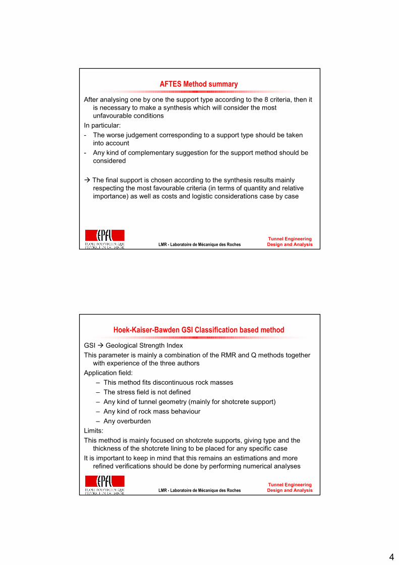
Remarks
This classification is limited to horseshoe shaped/rectangular tunnels supported by sets. It has been generalised to any geometry of the tunnel by DeereTerzaghi proposed also in 1943 an analytical solution which practically gives the resistance of the support B1 considering the width of the excavation B0, the height L and the friction angle ϕ. Moreover, he estimated also the pressure on the lining/support σv knowing the overburden H and the specific weight of the rock mass γ
1 0
tan1 1
2 2 tan4 2
1tan
HB
v
B B L
B eϕ
π ϕ
γσϕ
−
= + −
= −
Tunnel Engineering Design and AnalysisLMR - Laboratoire de Mécanique des Roches
Rock load estimation (1/3)
Light support for protection against spalling.
0 to 0.25 B
Massive rock contains widely spaced joints and fractures. Block size is large. Joints are interlocked. Vertical walls do not require support. Spalling may occur.
III. Massive, moderately jointed
Light support for protection against spalling. Load may change between layers.
0 to 0.5 B
Hard rock consists of thick strata and layers. Interface between strata is cemented. Popping and spalling at excavated face is common.
II. Hard stratified and schistose
Light lining required only if spalling or popping occurs.
0
Hard and intact rock contains no joints and fractures. After excavation the rock may have popping and spalling at excavated face.
I. Hard and intact
Remark*(B and Ht in feet)
Rock Load Factor Hp (feet)*
DefinitionRock Class

7
Tunnel Engineering Design and AnalysisLMR - Laboratoire de Mécanique des Roches
Rock load estimation (2/3)
No side pressure.0.25 B to 0.35 (B + Ht)
Rock contains moderately spaced joints. Rock is not chemically weathered and altered. Joints are not well interlocked and have small apertures. Vertical walls do not require support. Spalling may occur.
IV. Moderately blocky and seamy
Considerable side pressure. Softening effects by water at tunnel base. Use circular ribs or support rib lower end.
1.1 (B + Ht)
Rock is not chemically weathered, and highly fractured with small fragments. The fragments are loose and not interlocked. Excavation face in this material needs considerable support.
VI. Completely crushed but chemically intact
Little or no side pressure.
(0.35 to 1.1) (B + Ht)
Rock is not chemically weathered, and contains closely spaced joints. Joints have large apertures and appear separated. Vertical walls need support.
V. Very blocky and seamy
Remark*(B and Ht in feet)
Rock Load Factor
Hp (feet)*DefinitionRock Class
Tunnel Engineering Design and AnalysisLMR - Laboratoire de Mécanique des Roches
Rock load estimation (3/3)
Circular ribs required. In extreme cases use yielding support.
up to 250 feet, irrespective of B and Ht
Rock volume expands (and advances into the tunnel) due to swelling of clay minerals in the rock at the presence of moisture.
IX. Swelling rock
(2.1 to 4.5) (B + Ht)
Rock slowly advances into the tunnel without perceptible increase in volume. Great depth is considered as more than 1000 m.
VIII. Squeezing rock at great depth
Heavy side pressure. Invert struts required. Circular ribs recommended.
(1.1 to 2.1) (B + Ht)
Rock slowly advances into the tunnel without perceptible increase in volume. Moderate depth is considered as 150 ~ 1000 m.
VII. Squeezing rock at moderate depth
Remark*(B and Ht in feet)
Rock Load Factor
Hp (feet)”DefinitionRock Class

8
Tunnel Engineering Design and AnalysisLMR - Laboratoire de Mécanique des Roches
Unsupported span effects
The unsupported span effect has been estimated by Terzaghi as the interval between the excavation and the failure of the crown without support. This interval duration is different according to the rock mass conditions
Tunnel Engineering Design and AnalysisLMR - Laboratoire de Mécanique des Roches
Caquot solutionsBasics assumptions:1. Circular tunnel2. Hydrostatic and uniform stress field3. Continuous medium4. Cohesive ground mass5. Low overburden6. Elasto-plastic material characterised by
Mohr Coulomb parameters:- Friction angle φ- Cohesion c
Solution:
The tunnel is full of a fluid characterised by the same specific weight of the surrounding ground. The solution can be found by estimating the load that may cause the failure.
The failure happens when the plastic radius reach the surface. This solution can also be applied for esitmating the overburden corresponding to a failure by equating the internal pressure to zero.
9
Tunnel Engineering Design and AnalysisLMR - Laboratoire de Mécanique des Roches
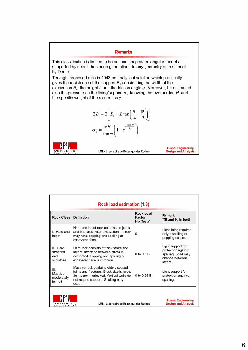
Caquot equations
( ) ( )1 2
1 12
K K
i
a a ap Hh K h
γ− − = − − + − −
WithH=c/tan(φ)K=tan²(π/4+φ/2)
Tunnel Engineering Design and AnalysisLMR - Laboratoire de Mécanique des Roches
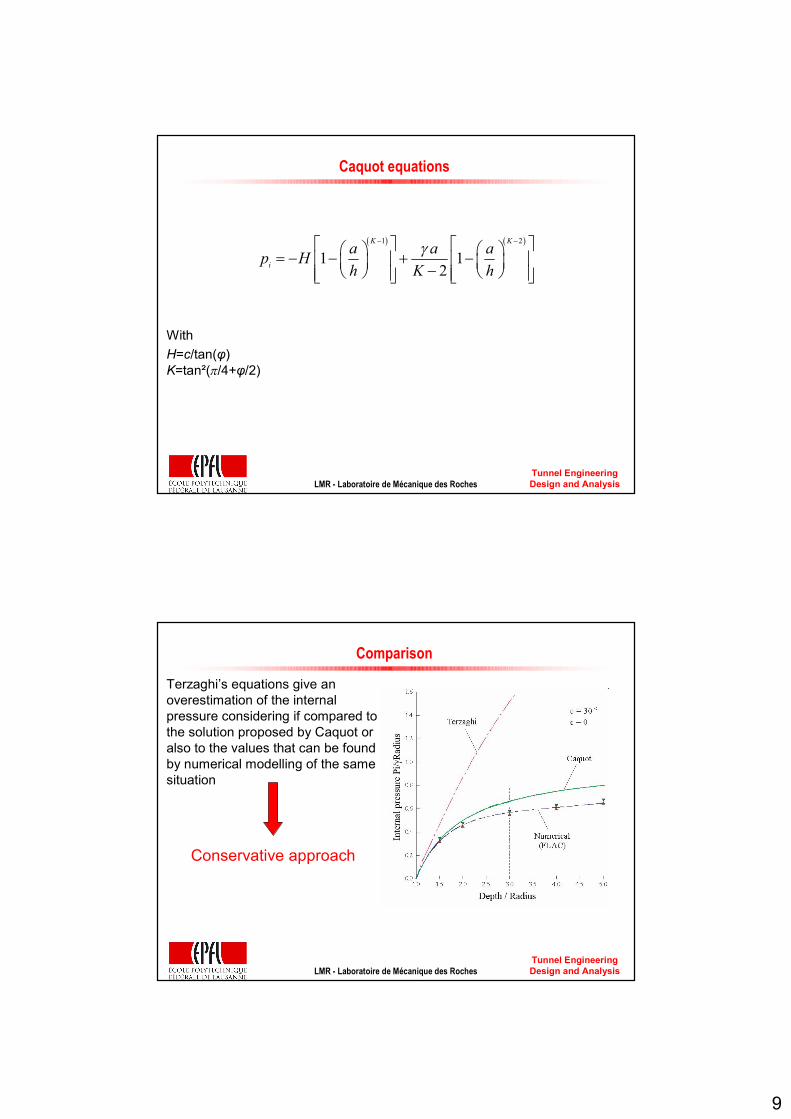
Comparison
Terzaghi’s equations give an overestimation of the internal pressure considering if compared to the solution proposed by Caquot or also to the values that can be found by numerical modelling of the same situation
Conservative approach
10
Tunnel Engineering Design and AnalysisLMR - Laboratoire de Mécanique des Roches
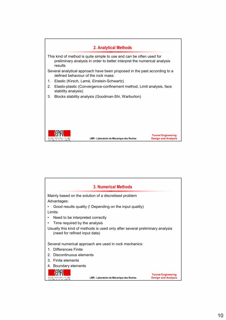
2. Analytical Methods
This kind of method is quite simple to use and can be often used for preliminary analysis in order to better interpret the numerical analysis results
Several analytical approach have been proposed in the past according to a defined behaviour of the rock mass:
1. Elastic (Kirsch, Lamé, Einstein-Schwartz)2. Elasto-plastic (Convergence-confinement method, Limit analysis, face
stability analysis)3. Blocks stability analysis (Goodman-Shi, Warburton)
Tunnel Engineering Design and AnalysisLMR - Laboratoire de Mécanique des Roches
3. Numerical Methods
Mainly based on the solution of a discretised problemAdvantages:• Good results quality (! Depending on the input quality) Limits:• Need to be interpreted correctly• Time required by the analysisUsually this kind of methods is used only after several preliminary analysis
(need for refined input data)
Several numerical approach are used in rock mechanics:1. Differences Finite2. Discontinuous elements3. Finite elements4. Boundary elements

11
Tunnel Engineering Design and AnalysisLMR - Laboratoire de Mécanique des Roches
Support design methods - Summary
• Empirical method ok only for first estimations at the preliminary designstep
• Analytical methods ok for estimation at both study and realisation steps
• Numerical Methods ok for major details at the design and realisation steps but need major precisions for input data
Tunnel Engineering Design and AnalysisLMR - Laboratoire de Mécanique des Roches
Hyperstatic Reactions method
Analytical and Numerical method for dimensioning of structure’s support
Main references:Duddeck and Erdmann, 1985Bouvard-Lecoanet et al., 1988Leca and Clough, 1992

12
Tunnel Engineering Design and AnalysisLMR - Laboratoire de Mécanique des Roches
Main Principles
Simulates the interaction between the support and rock surrounding the tunnel through many independent springs (“Winkler” type)
Calculates the behaviour of the lining under applied loads
Great number of connections of the support with the surrounding rock à Hyperstatic problem / statically indeterminate
The method requires definition of the active loads acting on the support structure and mainly due to the rock mass– technical literature (Barton et al., 1974, Barton, 2002, Unal, 1983, Goel
et al., 1995, Goel et al., 1996, Singh et al., 1992, Singh et al., 1997and Bieniawski, 1989).
– in situ monitoring, using back-analysis proceduresFurther passive loads are due to the reaction of the rock mass to the
displacement of the support structure
Tunnel Engineering Design and AnalysisLMR - Laboratoire de Mécanique des Roches
Hyperstatic Reactions methods - Loads
The support–rock interaction influences the stress state in the structure to a great extent and this interaction depends on the mechanical characteristics of the rock mass.
Three parameters influence the stress state in a support structure:the applied active loads, the stiffness of the structure (normal stiffness and bending stiffness) the pressure-displacement relation that describes the interaction between the
structure and the rock mass
There are two different types of loads:1. ACTIVE which do not depend on the lining deformation but only on the
rock volume which act on the tunnel crown (dislocation charge)2. PASSIVE which describe the rock/ground mass reaction and which do
depend on the lining/support deformation

13
Tunnel Engineering Design and AnalysisLMR - Laboratoire de Mécanique des Roches
Interaction between ground pressures and loads on lining
ACTIVE loads
Tunnel Engineering Design and AnalysisLMR - Laboratoire de Mécanique des Roches
ACTIVE loads
These are the charges which act directly on the lining (support), independent of lining deformation such as dead weight, permanent and varying inside and outside charges and pressure from the surrounding ground
They depend on:• Tunnel depth (overburden)• Tunnel geometry (size and shape)• Rock / Ground mass quality
4 main types:1. Vertical charge on the tunnel crown2. Horizontal charge3. Hydrostatic charges4. Others
14
Tunnel Engineering Design and AnalysisLMR - Laboratoire de Mécanique des Roches
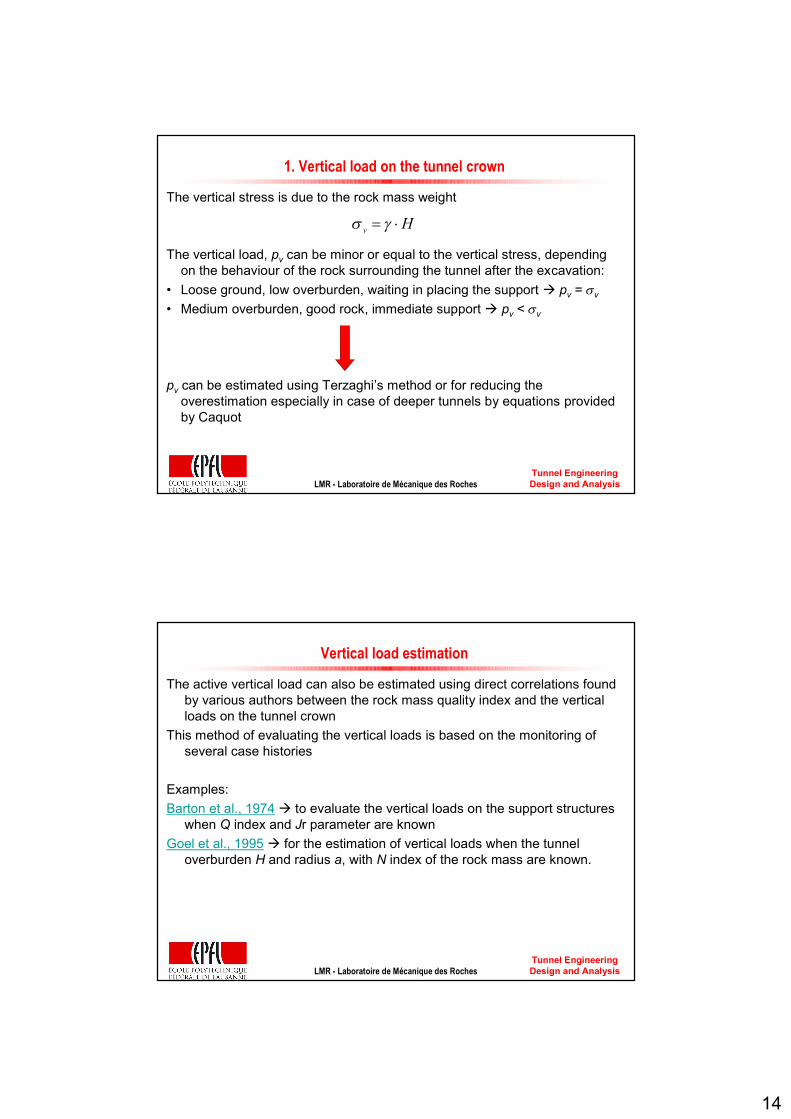
1. Vertical load on the tunnel crown
The vertical stress is due to the rock mass weight
The vertical load, pv can be minor or equal to the vertical stress, depending on the behaviour of the rock surrounding the tunnel after the excavation:
• Loose ground, low overburden, waiting in placing the support à pv = σv
• Medium overburden, good rock, immediate support à pv < σv
pv can be estimated using Terzaghi’s method or for reducing the overestimation especially in case of deeper tunnels by equations provided by Caquot
v Hσ γ= ⋅
Tunnel Engineering Design and AnalysisLMR - Laboratoire de Mécanique des Roches
Vertical load estimation
The active vertical load can also be estimated using direct correlations found by various authors between the rock mass quality index and the vertical loads on the tunnel crown
This method of evaluating the vertical loads is based on the monitoring of several case histories
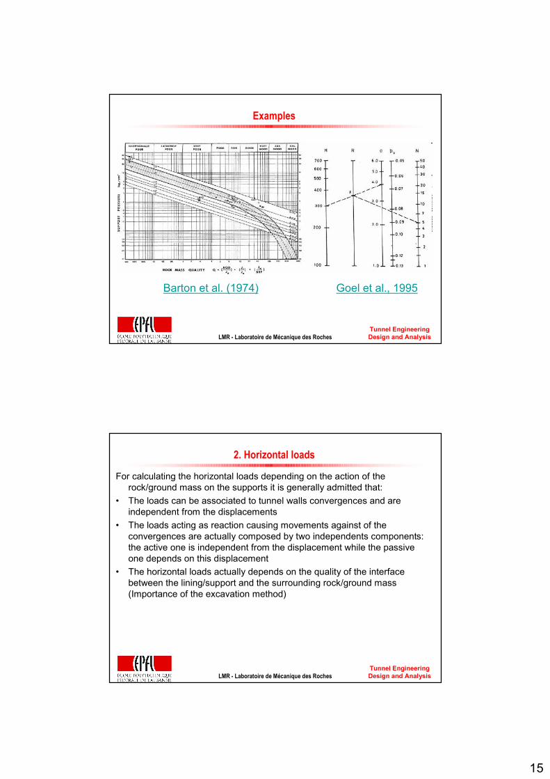
Examples:Barton et al., 1974à to evaluate the vertical loads on the support structures
when Q index and Jr parameter are knownGoel et al., 1995 à for the estimation of vertical loads when the tunnel
overburden H and radius a, with N index of the rock mass are known.
15
Tunnel Engineering Design and AnalysisLMR - Laboratoire de Mécanique des Roches
Examples
Barton et al. (1974) Goel et al., 1995
Tunnel Engineering Design and AnalysisLMR - Laboratoire de Mécanique des Roches
2. Horizontal loads
For calculating the horizontal loads depending on the action of the rock/ground mass on the supports it is generally admitted that:
• The loads can be associated to tunnel walls convergences and areindependent from the displacements
• The loads acting as reaction causing movements against of the convergences are actually composed by two independents components: the active one is independent from the displacement while the passive one depends on this displacement
• The horizontal loads actually depends on the quality of the interface between the lining/support and the surrounding rock/ground mass (Importance of the excavation method)

16
Tunnel Engineering Design and AnalysisLMR - Laboratoire de Mécanique des Roches
Horizontal loads estimation
The horizontal loads acting on the tunnel side walls are usually considered to be a percentage of the vertical loads
The ratio between the horizontal and vertical loads on the support structure is:
• lower than the in situ stress ratio K0à high quality rock mass• higher than K0 à for very crushed rock masses and for squeezing and
swelling ground
Tunnel Engineering Design and AnalysisLMR - Laboratoire de Mécanique des Roches
Terzaghi’s Rock Load Classification (modified by Deere et al.,1970)
Horizontal loads also called side pressures increase with the decreasing quality of the rock mass:
• Lower with medium to good geomechanical quality of the rock mass is medium or good
• Higher when the quality of the rock mass is very poor (i.e. completely crushed rock)

17
Tunnel Engineering Design and AnalysisLMR - Laboratoire de Mécanique des Roches
Horizontal load estimation (Terzaghi)
By analysing the potential instability of the rock mass on the tunnel sides considering a planar sliding surface, it is possible to evaluate the qh/qv ratio in function of the vertical load qv, the tunnel height Ht, the specific weight γ and the strength parameters c and φ of the rock mass:
( )
tan1 1tan12 1 tan tan sin cos sin tan
h t
v v v
q H cq q q
ϕγ α
ϕ α α α α ϕ
− = + ⋅ − ⋅ + ⋅ ⋅ + ⋅
Where α is the slope of the sliding surface:4 2π ϕα = +
Tunnel Engineering Design and AnalysisLMR - Laboratoire de Mécanique des Roches
3. Hydrostatic loads
The presence of water should be taken into account on the whole perimeter of the tunnel
18
Tunnel Engineering Design and AnalysisLMR - Laboratoire de Mécanique des Roches
4. Other active loads
• Existing loads (e.g. buildings, etc.) on the ground surface• The dead weight of the support (which can be neglected when the
overburden is high)• The operation load acting at the tunnel intrados (e.g. hydraulic tunnels)• The temporary loads mainly depending on the construction methods (e.g.
compressed air, injections, etc..)
Tunnel Engineering Design and AnalysisLMR - Laboratoire de Mécanique des Roches
PASSIVE loads
Passive loads are necessary for equating ground and lining deformation due to loadsThese loads mainly depend on the deformation of the surrounding rock/ground massThe main hypothesis consists into considering that the reaction is directly proportional to the displacement
Lining deformation à considering the strength of the material and the lining as a plane arch or thick ring…Ground deformations à the reaction modulus which is considered proportional to the deformation in any point of the surrounding rock
q K u= ⋅r r

19
Tunnel Engineering Design and AnalysisLMR - Laboratoire de Mécanique des Roches
Reaction Modulus, K
K is the reaction modulus describing the interaction of the rock/ground mass with the excavated tunnel.When the tunnel is circular (or approximately circular)
withR = tunnel radiusE, ν = Young’s modulus and Poisson’s coefficient of the rock/ground mass
If the tunnel has a different geometry then it is necessary to use other formula (e. g. Dislocation charges by Caquot & Kérisel, 1966)
(1 )EK
Rν=
+ ⋅
Tunnel Engineering Design and AnalysisLMR - Laboratoire de Mécanique des Roches
Calculation scheme
Active loads are applied to the tunnel support by the rock mass in the roof (vertical loads, qv = pv) and on the lateral sides (horizontal loads, qh = ph)The active loads are independent of the displacements that develop in the support and at the rock-support interface.
qv: vertical load qh: horizontal loadkn: stiffness of the interaction springsR: tunnel radius E · J, E · A: bending and normal stiffness of the support
20
Tunnel Engineering Design and AnalysisLMR - Laboratoire de Mécanique des Roches
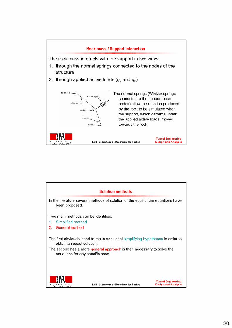
Rock mass / Support interaction
The rock mass interacts with the support in two ways: 1. through the normal springs connected to the nodes of the
structure 2. through applied active loads (qv and qh).
The normal springs (Winkler springs connected to the support beam nodes) allow the reaction produced by the rock to be simulated when the support, which deforms under the applied active loads, moves towards the rock
Tunnel Engineering Design and AnalysisLMR - Laboratoire de Mécanique des Roches
Solution methods
In the literature several methods of solution of the equilibrium equations have been proposed.
Two main methods can be identified:1. Simplified method2. General method
The first obviously need to make additional simplifying hypotheses in order to obtain an exact solution,
The second has a more general approach is then necessary to solve the equations for any specific case
21
Tunnel Engineering Design and AnalysisLMR - Laboratoire de Mécanique des Roches
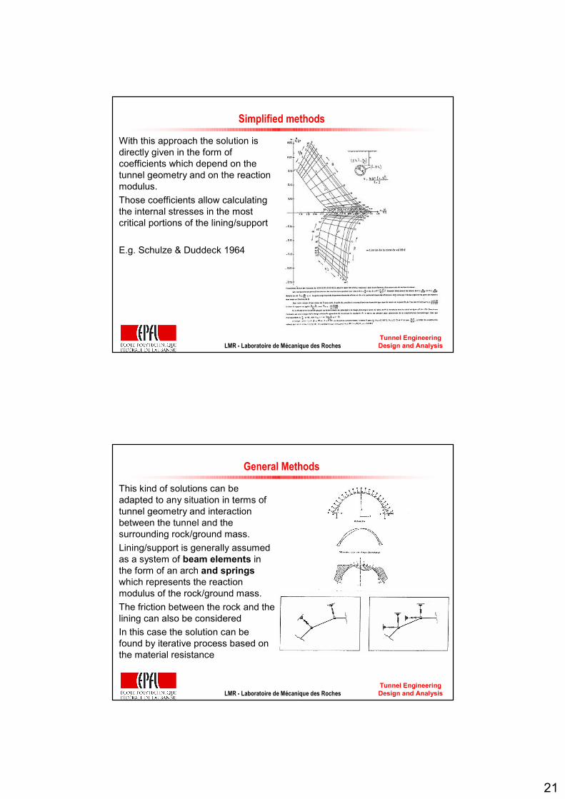
Simplified methods
With this approach the solution is directly given in the form of coefficients which depend on the tunnel geometry and on the reaction modulus. Those coefficients allow calculating the internal stresses in the most critical portions of the lining/support
E.g. Schulze & Duddeck 1964
Tunnel Engineering Design and AnalysisLMR - Laboratoire de Mécanique des Roches
General Methods
This kind of solutions can be adapted to any situation in terms of tunnel geometry and interaction between the tunnel and the surrounding rock/ground mass.Lining/support is generally assumed as a system of beam elements in the form of an arch and springswhich represents the reaction modulus of the rock/ground mass.The friction between the rock and the lining can also be consideredIn this case the solution can be found by iterative process based on the material resistance

22
Tunnel Engineering Design and AnalysisLMR - Laboratoire de Mécanique des Roches
Hyperstatic reactions method calculation
The lining is represented by beam elements (for which it is possible to describe the stress–strain law in a simple way), which are connected to the outside through springs (i.e. stiffnesses) distributed over the nodes
The support structure is therefore represented, in the calculation, by mono-dimensional elements that are able to develop bending moments, axial forces and shear forces
Scheme of the behaviour of a beam-type finite element (x and y local Cartesian coordinates):h: the initial nodej: the final nodeu: the axial displacementv: the transversal displacementφ: the rotation
Tunnel Engineering Design and AnalysisLMR - Laboratoire de Mécanique des Roches
Support geometry influence
Apart from the interaction with the rock mass, the behaviour of the support is also influenced by its bending and normal stiffness and the restraining conditions that are assumed.
Bending and normal stiffnesses depend on the elastic modulus of the support material and on the geometry of its section.
The type of constraint at the foot can influence the support behaviour to a great extent and depends on the type of foundations and on the geometry of the support.

23
Tunnel Engineering Design and AnalysisLMR - Laboratoire de Mécanique des Roches
Equivalent support concept
The most commonly used type of preliminary support structure in tunnels:- steel sets- ShotcreteThis is a composite system for which it is necessary to define a normal and a
bending equivalent stiffness in order to be able to use a bi-dimensional calculation method.
à equivalent support made up of homogeneous material for which it is possible to estimate the thickness and the elastic modulus knowing the the parameters characterising the shotcrete and the steel sets
Tunnel Engineering Design and AnalysisLMR - Laboratoire de Mécanique des Roches
Advantages and LimitsAdvantages:Easy of employFast sensitivity analyses by changes parameters describing the rock mass and lining behaviourParticularly suitable for the dimensioning of the most widely used support structures in tunnels:
steel sets & shotcreteThe method allows the results of the bending moment, the shear forces and the normal force
along the support profile
Limits:The evaluation of the active vertical loads: incertitude that grows with increasing overburdenIt is difficult to correctly evaluate the active horizontal loads (measuring?) and also to determine
the quality of the interface between lining and surrounding (local solution provided by GEORADAR measured) à not guaranteed that the interface can absorb shear stresses, very difficult to estimate the shear stiffness value. Note that when the shear stiffness on the interface is neglected, the bending moments are greater both in the crown and in the sidewalls (conservatory hypothesis)
It is quite difficult to measure the reaction modulus (it mainly depends on the type of tests in situ or in laboratory)
The reaction produced by the rock mass on the deformations of the support is also a function of the stiffness of the structure. This only depends on the mechanical and geometrical characteristics of the support. During calculation it is necessary to verify the compatibility of the stress and strain state with the maximum admissible conditions

24
Tunnel Engineering Design and AnalysisLMR - Laboratoire de Mécanique des Roches
CV-CF vs. HRM
Depthà CV-CF for deep tunnels (H>>10R)à HRM for lower overburden (H<5-10R)Relative stiffnessà CVCF stiffer rock massà HRM stiffer liningRock/ground massà CVCF rockà HRM soil and fissured rockSupporting Structureà CVCF temporary supportà HRM temporary support and definitive liningStudy/Project stepsà CVCF project and execution (estimation)à HRM project (estimation)
Tunnel Engineering Design and AnalysisLMR - Laboratoire de Mécanique des Roches
Support design methods - Comparison
According to the type of results and to the analysis approach it is also possible to distinguish 3 different families of methods:
I. Empirical methodsII. Analysis of stress and displacement distribution in the rock mass
surrounding the excavation III. Lining behaviour analysis