Embed Size (px)
Citation preview

8/10/2019 Tunnel Face Pressure
http://slidepdf.com/reader/full/tunnel-face-pressure 1/11
European Journal of Scientific Research
ISSN 1450-216X Vol.36 No.4 (2009), pp.595-605
© EuroJournals Publishing, Inc. 2009http://www.eurojournals.com/ejsr.htm
Analysis of Underground Market Settlement in Tabriz
Urban Railway
M.J.Vahdatirad
Department of Civil Engineering, Babol University of Technology, Babol, Iran
E-mail: [email protected]
H.Ghodrat
Faculty of Engineering, Tarbiat Moallem University, Tehran, Iran
S.Firuzian
Department of Civil Engineering, Babol University of Technology, Babol, Iran
A.Barari
Department of Civil Engineering, Babol University of Technology, Babol, Iran
M. Torabi
Faculty of Mining, Petroleum and Geophysics, Shahrood University of Technology
Abstract
Tunnel of Tabriz urban railway line2 (TURL2) will pass an underground market onits way. Short distance between tunnel crown and underground market foundation will
probably cause collapses or excessive settlements during tunnel construction based on
conducted investigations into geotechnical conditions of the region. Using finite elementmethod, the quantity of underground market foundation settlement is estimated in this
paper. Then, considering allowable settlement concluded from risk analysis and acceptable
risk level, some measures are suggested for settlement reduction. The results show that inorder to lessen volume loss, underground market settlement can be controlled using
grouting methods and simultaneously special measures.
Keywords: Mechanized Tunneling, Settlement, modeling, Grouting, PLAXIS.
1. Introduction
Tabriz with 1602
km area and the population about 1,360,000 is one of most crowded and important
cities in northwestern Iran. According to conducted traffic and transportation studies, 4 light urbanrailways, 48 km in length (extendable to 72 km), are considered for this city (Fig.1). Studies and design
of Tabriz urban railway line 2 (TURL2) have been commenced since 2006. TURL2 20 km in length
will connect eastern part of the city to its western part and will pass crowded parts of the city such astrading centers on its way. In the city center, the crown of TURL2 tunnel, excavated by an EPB-TBM
machine 9.2m in diameter, passes under an underground market foundation at a distance of about
13.1m (Fig. 2). The foundation of the market, 1.5m thick, is 5.86m deep (Fig.3). Based on studied

8/10/2019 Tunnel Face Pressure
http://slidepdf.com/reader/full/tunnel-face-pressure 2/11
Analysis of Underground Market Settlement in Tabriz Urban Railway 596
geotechnical condition of the region including shallow water table, low cohesion and medium densitymaterials, it is of great importance to study probable settlements.
The problem of tunnel-induced settlements has interested many researchers over the past 40
years and many literature presented (among others, by Peck, 1969 [[1]]; Cording et al., 1975 [[2],[3]];Mair et al., 1996 [[4]], 1997[[5]]; Attewell et al., 1982[[6]], 1984[[7]]; Rankin, 1988[[8]]; New et al.,
1991 [[9]]; Leblais et al., 1995 [[10]]). Moreover, Selby (1988) based on a numerical modeling studied
transmission of settlements upwards to the surface in a homogeneous medium and in a layered medium
with different consistency of the strata [[11]]. Further, because of recent progress in the ability oftunneling machines to cope with difficult ground conditions, the ground movements produced have
been greatly reduced [[12]]. A Working Group of the French Tunneling Association has published asubstantial and authoritative review paper ‘Settlements Induced by Tunneling’[13]].
In this paper, using PLAXIS finite element software code, site condition is simulated and the
foundation settlement is estimated. Owing to the fact that settlement value exceeds the accepted
quantity (resulted from risk analysis), influence of volume loss reduction and improvement of soilgeotechnical parameters, using slurry grouting, is studied. Results show that underground market
foundation settlement could be controlled using measures for volume loss reduction and improvement
of geotechnical parameters of soil layers by grouting simultaneously.
Figure 1: Tabriz urban railways

8/10/2019 Tunnel Face Pressure
http://slidepdf.com/reader/full/tunnel-face-pressure 3/11
597 M.J.Vahdatirad, H.Ghodrat, S.Firuzian, A.Barari and M. Torabi
Figure 2: Underground market plan in TURL2 corridor
Figure 3: Underground market section
2. Allowable Settlement based on Building Risk Analysis (BRA)The Building Risk Assessment – BRA – to estimate the potentially expected damages on the basis of
settlement predictions and the intrinsic vulnerability of the structures is Considered, [[14]]. By a
feedback method, the allowable settlement is estimated based on BRA.
2.1. Damage classification and concept of risk
For structures with isolated foundations, the classification is given by Rankine (1988) that fixes limit
values for settlement and angular deformation [[8]].
8/10/2019 Tunnel Face Pressure
http://slidepdf.com/reader/full/tunnel-face-pressure 4/11
Analysis of Underground Market Settlement in Tabriz Urban Railway 598
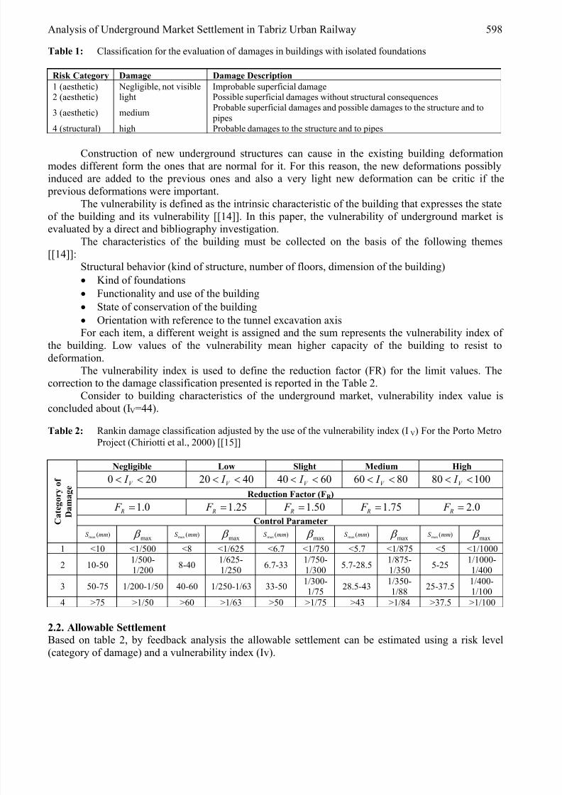
Table 1: Classification for the evaluation of damages in buildings with isolated foundations
Risk Category Damage Damage Description
1 (aesthetic) Negligible, not visible Improbable superficial damage2 (aesthetic) light Possible superficial damages without structural consequences
3 (aesthetic) mediumProbable superficial damages and possible damages to the structure and to
pipes
4 (structural) high Probable damages to the structure and to pipes
Construction of new underground structures can cause in the existing building deformation
modes different form the ones that are normal for it. For this reason, the new deformations possiblyinduced are added to the previous ones and also a very light new deformation can be critic if the
previous deformations were important.
The vulnerability is defined as the intrinsic characteristic of the building that expresses the state
of the building and its vulnerability [[14]]. In this paper, the vulnerability of underground market isevaluated by a direct and bibliography investigation.
The characteristics of the building must be collected on the basis of the following themes
[[14]]:Structural behavior (kind of structure, number of floors, dimension of the building)
•
Kind of foundations• Functionality and use of the building
• State of conservation of the building
• Orientation with reference to the tunnel excavation axisFor each item, a different weight is assigned and the sum represents the vulnerability index of
the building. Low values of the vulnerability mean higher capacity of the building to resist to
deformation.
The vulnerability index is used to define the reduction factor (FR) for the limit values. Thecorrection to the damage classification presented is reported in the Table 2.
Consider to building characteristics of the underground market, vulnerability index value is
concluded about (IV=44).
Table 2: Rankin damage classification adjusted by the use of the vulnerability index (IV) For the Porto Metro
Project (Chiriotti et al., 2000) [[15]]
Negligible Low Slight Medium High
200 << V I 4020 << V I 6040 << V I 8060 << V I 10080 << V I
Reduction Factor (FR )
0.1= R F 25.1= R F 50.1= R F 75.1= R F 0.2= R F
Control Parameter C a t e g o r y o f
D a m a g e
)(max mmS max β )(max mmS
max β )(max mmS max β )(max mmS
max β )(max mmS max β
1 <10 <1/500 <8 <1/625 <6.7 <1/750 <5.7 <1/875 <5 <1/1000
2 10-501/500-1/200
8-401/625-1/250
6.7-331/750-1/300
5.7-28.51/875-1/350
5-251/1000-1/400
3 50-75 1/200-1/50 40-60 1/250-1/63 33-501/300-1/75
28.5-431/350-1/88
25-37.51/400-1/100
4 >75 >1/50 >60 >1/63 >50 >1/75 >43 >1/84 >37.5 >1/100
2.2. Allowable Settlement
Based on table 2, by feedback analysis the allowable settlement can be estimated using a risk level
(category of damage) and a vulnerability index (Iv).

8/10/2019 Tunnel Face Pressure
http://slidepdf.com/reader/full/tunnel-face-pressure 5/11
599 M.J.Vahdatirad, H.Ghodrat, S.Firuzian, A.Barari and M. Torabi
Assuming light damage to underground market building and using table 1 the risk category isobtained. Therefore, assuming risk category and vulnerability index respectively equal to 2 and 44, the
allowable settlement is obtained about 28mm using table 2.
3. Estimation of maximum settlement of underground market foundationDespite the fact that the presence of existing buildings at the ground surface will modify the
development of ground movements depending on the proximity of the structures to the tunnel, it isimportant to understand the development of tunneling induced settlements on a greenfield site before
considering the added complexity of an existing building [[14]].Calculation of underground market foundation settlement due to mechanized tunneling, by
EPB-TBM machines, is done by PLAXIS finite element software code [[17]]. In this software after
defining geometry of the problem, assigning geotechnical specifications of soil layers, segmentsmaterial and water table, settlement calculation and stress-strain analysis are done through two phases
by stage construction capability of the software. Simulating process, calculation phases and results are
presented following.
3.1. Geometry
According to dimensions presented in the figure 3, geometry of the model is defined in PLAXISsoftware (Fig4).
Figure 4: Geometry of the model
3.2. Material specification and water table condition
Based on conducted studies in the corridor of TURL2, soil of mentioned region is mainly silt with low plasticity (ML) and silty sand (SM) and water table is 8.8m deep. Geotechnical specifications used for
soil layers of the model are presented in table3.
Table 3: Geotechnical specifications used for soil layers of the model
IdMaterial
model
Dry
density
(kn/m3)
Type
Wet
density
(kn/m3)
Permeabili
ty (m/day)
Elastic
modulus
(kn/m2)
Poisson
ratio
Cohesion
(kn/m2)
Internal
friction
angle
MLMohr-Coulomb
Drained 16.7 20 0.00423 4E04 0.35 17 27
SMMohr-Coulomb
Drained 16.4 19.8 0.043 6.5E04 0.3 7 34

8/10/2019 Tunnel Face Pressure
http://slidepdf.com/reader/full/tunnel-face-pressure 6/11
Analysis of Underground Market Settlement in Tabriz Urban Railway 600
Moreover, Beam element is used for modeling of segments and its specifications are presentedin table 4.
Table 4: Specifications of beam elements for modeling of segment
ID Material Model Ea (kn/m) Ei (kn/m2/m) D (m) W (kn/m/m) Poisson Ratio
Segment Elastic 1.103E07 1.125E05 0.35 8.4 0.15
3.3. Loading
In order to calculate the settlement, considered values for traffic load, underground market weight andthe weight of structures close to underground market modeled in type of spread load are shown in table
5.
Table 5: The amounts of various types of load in the model
ID Traffic Load Underground Market Vicinity Houses
Amount (kn/m2) 20 7 35
3.4. Settlement calculation
Settlement calculation shows that the amount of underground market foundation settlement based on
assumed value of 1% volume loss (tunnel contraction) is equal to 46.24mm. Vertical displacement
contours are depicted in figure 5. According to mentioned figure, maximum vertical displacementexceeds from allowed settlement resulted from accepted risk level.
Figure 5: Calculated vertical displacement of underground market
4. Influence of volume loss reduction on underground market settlementGround movements are an inevitable consequence of excavating and constructing a tunnel. During the
process of excavation, it will always be necessary to remove a larger volume of ground than the
theoretical volume of the finished void to avoid of the stress relief. This extra volume excavated is
known as “volume loss” and is expressed in terms of unit distance advance of the excavation thatcauses the relaxation (i.e. m3 per meter advance). In other words, volume loss/area of cross section ×
100 is the expression that is normally used for VL [[14]].

8/10/2019 Tunnel Face Pressure
http://slidepdf.com/reader/full/tunnel-face-pressure 7/11
601 M.J.Vahdatirad, H.Ghodrat, S.Firuzian, A.Barari and M. Torabi
The magnitude of the movements causing the volume loss is a function of the soil type, rate oftunnel advance, tunnel diameter, excavation method, and form and stiffness of temporary and primary
support. In the specific case of mechanized tunneling, the individual factors contributing to volume
loss are the “face loss” and the “radial loss” (Fig 6) [[14]].
Figure 6: The factors contributing to the volume loss
The sum of the “face loss” and the “radial loss” gives the overall volume loss, VL. The face lossis very limited if the tunnel face is properly pressurized and the radial loss is easily controlled byinjection of an adequate volume of grout at the right pressure, with a proper grouting mix design.
Recent experiences with closed-face mechanized tunneling (EPB and Slurry Shields) have generally
shown that in sands and gravels, a high degree of settlement control can be achieved and small volumelosses are recorded (i.e. often VL < 0.5%), while in soft clays, VL ranges between 1 and 2%, excluding
the long-term settlements. Leblais (1995) reported volume losses in the range 0.2–0.9% for 9.25-m
diameter tunnels driven through dense, fine Fontainebleau sands at depths ranging from 22 m to 52 m
[[10]].In this study, the soil type to be excavated is silty sand and tunnel diameter and depth of crown
are 9.15m and 13.1m respectively. Hence, it can be estimated a value range of 0.5-1.5% for VL
assigned by contraction factor in PLAXIS software.On account of the fact that some parameters such as soil type, tunnel diameter and excavation
method and form of supports are constant in this study, the magnitude of the movements causing
volume loss can be reduced affected by the rate of tunnel advance.Figure 7 shows the result of analysis by different VL in a range of 0.5-1.5%. The figure curves
show that maximum settlement of underground market foundation and tunnel crown displacement
decreases as a consequence of VL reduction and reaches to the minimum value of 32 mm at VL=0.5,yet in this range of VL, settlements will always be more than the maximum allowable settlement (28
mm).Figure 7: Influence of Vs amounts on underground market settlement

8/10/2019 Tunnel Face Pressure
http://slidepdf.com/reader/full/tunnel-face-pressure 8/11
Analysis of Underground Market Settlement in Tabriz Urban Railway 602
0
10
20
30
40
50
60
70
80
90
0.5 1 1.5
Volume Loss (%)
M a
x .
v e r t i c a l d i s p l a c e m e n t ( m m )
S underground market (mm) S tunnel crown (mm)
5. Influence of soil improvement on underground market settlement
Improving geotechnical characteristics of soil affected by tunneling settlement of underground marketfoundation can be controlled. Therefore, modeling is done according to improved characteristics of permeable soil existing under the market assuming cement slurry grouting (table 6) [[18]].
Table 6: improved characteristics of soil resulted from cement slurry grouting
IDMaterial
ModelType
Wet Density
(KN/m3)
Permeability
(m/day)
Elastic Modulus
(KN/m2)Poisson Ratio
Grout Linear Elastic Drained 24 2E-05 9.87E06 0.2
In order to reduce maximum vertical settlement of underground market foundation, modeling isdone assuming constant value for VL parameter (1%) and using vertical direction slurry grouting in
sandy layer existing under the market (Fig 8). Various models with different grouting depths from thetop of sandy layer down to bedrock is prepared and analyzed. Maximum vertical settlement ofunderground market foundation versus grouting depth in sandy layer is shown in figure 9.
Figure 8: a sample of made models with vertical direction grouting in sandy layer under the market
As shown in figure 9, an increase in grouting thickness leads to a decrease in maximum vertical
settlement of underground market foundation to the minimum value of 5.8 mm, when grouting layer
thickness equals to 23.86 m (bedrock). According to this figure, allowed settlement occurrs in the
grouting depth equal to 16.88 m.

8/10/2019 Tunnel Face Pressure
http://slidepdf.com/reader/full/tunnel-face-pressure 9/11
603 M.J.Vahdatirad, H.Ghodrat, S.Firuzian, A.Barari and M. Torabi
Figure 9: Influence of soil improvement on underground market settlement
0
10
20
30
40
50
60
0 5 10 15 20
Improved layer Thickness by cement slurry grouting (m) M a x . v e r t i c a l d i s p l a c e m e n t ( m m )
S underground market (mm)
S tunnel crown (mm)
6. Influence of VL reduction and soil improvement simultaneously on underground
market settlementIgnoring influence of soil improvement on VL value reduction, influence of soil improvement and VL
value reduction simultaneously are analyzed. In this case, various models with different VL values and
different grouting depths are made and the results are shown in figure 10. According to the mentionedfigure, simultaneous influence of soil improvement and VL value reduction causes more rapid slowing
down rates in maximum vertical settlement of underground market foundation. Minimum value of
settlement equal to 4.86 mm occurrs in the grouting depth and VL value equal to 23.86 m and 0.5%
respectively. According to the mentioned figure, allowable settlement is resulted in various groutingdepths and VL values shown in table 7.
Figure 10: Influence of soil improvement using slurry grout on underground market settlement
0
10
20
30
40
50
60
70
80
0 5 10 15 20 25
Improved layer Thickness by cement slurry grouting (m)
M a x .
v e r t i c a l d
i s p l a c e m e n t ( m m )
VL=1.3 (%) VL=1.1 (%) VL=0.9 (%) VL=0.7 (%) VL=0.5 (%) VL=1.0 (%) VL=1.5 (%)
Table 7: Volume loss values and improved soil thicknesses leading to allowable settlement

8/10/2019 Tunnel Face Pressure
http://slidepdf.com/reader/full/tunnel-face-pressure 10/11
Analysis of Underground Market Settlement in Tabriz Urban Railway 604
Volume Loss (%) Improved Soil Thickness (m)
0.5 11.54
0.7 14.27
0.9 16.07
1 16.881.1 17.24
1.3 18.19
1.5 19.11
7. ConclusionIn this paper an engineering practical problem of an Underground Market foundation settlementinduced by tunneling including the results of a case study conducted on an urban railway project in
Tabriz, northwestern Iran, are discussed.
Using finite element method, PLAXIS software, and based upon conducted geotechnical
studies site condition is simulated and the foundation settlement is estimated and compared toallowable settlement resulted from building risk analysis.
Considering obtained results, settlement value in underground market with VL=1%, without
consolidation measures is 46.24 mm, more than allowable settlement which is equal to 28mm.
Decreasing VL down to the minimum value of 0.5%, maximum settlement reaches to 32 mm exceedingallowable settlement. Using cement slurry grouting, 16.88 m thick, to improve the silty sand layer
under the market and maintaining VL equal to 1%, allowable settlement was achieved. Moreover,concurrent soil improvement and Volume Loss reduction led to allowable settlement for various
Volume Loss quantities between (0.5 % <VL<1.5%) and various grouting thicknesses between (11.54
m< Improved Soil Thickness<19.11 m).The investigation conducted in this research shows the sensitivity of settlement induced by
tunneling to the volume loss and soil geotechnical characteristics, particularly in special structure andunstable ground condition.
References[1] Peck, R. B., (1969), “Deep Excavations and Tunneling in Soft Ground”, Proc.: 7th International
Conf. Soil Mechanics and Foundation Engineering, Mexico, State-of-the-art volume, State-of-
the art Report, pp.225–290.
[2] Cording, E. J. and Hansmire, W. H., (1975), “Displacements around Soft Ground Tunnels”,Proc.: 5
th Pan American Conf. Soil Mechanics and Foundation Engineering, Buenos Aires, (4),
pp. 571–633.
[3] Boscarding, M. D., and Cording, E. G., (1989), “Building Response to Excavation-InducedSettlement”, Journal of Geotechnical Engineering, ASCE, 115; 1; 1-21.
[4] Mair, R. J., Taylor, R. N., and Burland, J. B., (1996), “Prediction of Ground Movements and
Assessment of Risk of Building Damage”, Geotechnical Aspects of Underground Construction
in Soft Ground, pp. 712-718, Balkema, Rotterdam.[5] Mair, R. J., and Taylor, R. N., (1997), “Bored Tunneling in the Urban Environment”, Proc.: 14
th
ICSMFE. Hamburg, pp. 2353–2385.[6] Attewell, P. B., and Woodman, (1982), “Predicting the Dynamics of Ground Settlement and its
Derivatives Caused by Tunneling in Soil”, Ground Eng. 15(8), pp.13–22.[7] Attewell, P. B., and Taylor, R. K., (1984), “Ground Movements and their Effects on
Structures”, Chapman and Hall.
[8] Rankin, W. J., (1988), “Ground Movements Resulting from Urban Tunneling: Predictions and
Effects”, Eng. Geol. of Underground Movements, pp.79–92.

8/10/2019 Tunnel Face Pressure
http://slidepdf.com/reader/full/tunnel-face-pressure 11/11
605 M.J.Vahdatirad, H.Ghodrat, S.Firuzian, A.Barari and M. Torabi
[9] New, B. M., and O’ReilIy, M. P., (1991), “Tunneling Induced Ground Movements; Predictingtheir Magnitude and Effects”, The 4th International Conference on Ground Movements and
Structures, invited review paper, Pentech Press, Cardiff, pp. 671–697.
[10] Leblais, Y., Andre, D., Chapeau, C., Dubois, P., Gigan, J. P., Guillaume, J., Leca, E., Pantet,A., and Riondy, G., (1995), “(eds), Settlements Induced by Tunneling”, AFTES
Recommendations.
[11] Selby, A. R., (1988), “Surface Movements Caused by Tunneling in Two-layer Soil”, Eng. Geol.
of Underground Movements, Nottingham, pp. 71–77.[12] Leca, E., New, B., (2007), “Settlement Induced by Tunneling in Soft Ground”, Tunneling and
Underground Space Technology, pp. 119-149.[13] Leblais, Y., Andre D., Chapeau, C., Dubois, P., Gigan, J.P, Guillaume, J., Leca, E., Pantet, A.,
Riondy, G., (1996), “Settlements induced by tunnelling”, Recommendations of Workgroup No
16 of AFTES, The French Tunnelling Association.
[14] Guglielmetti, V., Mahtab, A., Xu, S., Geodata S. p. A., Turin, Italy, (2008), “MechanizedTunneling un Urban Areas – Design methodology and construction control”, Taylor & Francis
group.
[15] Chiriotti, E., Marchionni, V. and Grasso, P., , (2000), “Porto light Metro System, Lines C, Sand J. Compendium to the Methodology Report on Building Risk Assessment Related to
Tunnel Construction”, Normetro – Transmetro, Internal technical report (in Italian andPortuguese).
[16] Grasso, P., Xu, S., Del Fedele, M., Russo, G. and Chiriotti, E., (2003), “Particular Failure
Mechanisms of Weathered Granite Observed During Construction of Metro Tunnels by TBM”,
Proc.: World Tunnel Congress. Amsterdam.
[17] PLAXIS 7.2, Professional Version (Build 09), Copyright 1998 PLAXIS B.V., KoxhiyokiKabuto, Japan, 7P105PKD 5d64c9d5 0ee09818
[18] Janalizadeh Choobbasti, A., Nikfard, R., Vahdatirad, M. J. and Hesami, S., (2008), “Control of
Jack Thrust Wall Displacement in Microtunnelling Method”, Electronic Journal ofGeotechnical Engineering, Vol.13, Bund. G.