Embed Size (px)
Citation preview
46 TRANSPORTATION RESEARCH RECORD 1316
Tunnel Lighting: Comparison and Tests of Symmetrical, Counter-Beam, and Pro-Beam Systems
J. M. DIJON AND p. WINKIN
Three tunnel lighting systems-symmetrical, counter-beam (CBL), and pro-beam (PBL)-were compared under the same geometrical and weather conditions to determine their advantages and disadvantages in terms of visibility. The PBL system was found to have no advantages over the other two system , and it should be used in combination with light, diffusing tunnel walls and road surfaces. The symmetrical system was found to provide good guidance when used with luminaires mounted in a continuous line, and the CBL system was found to ensure good perception of contrast and an acceptable level of glare, provided that certain conditions are met.
The main problem of tunnel lighting concerns the entrance zone extended over the length inside the tunnel corresponding to the safe stopping sight distance (SSSD).
The level of luminance L,h required in the threshold zone is defined in relation to the luminance level in the tunnel access zone L 20 at a distance equal to the SSSD from the tunnel mouth, according to the ratio k = L,h /L20 , where L,h is the luminance in the threshold zone and L20 is the luminance within a field of 20 degrees measured in the access zone in the direction of the traffic, where the center of the field of measurement coincides with the center of the tunnel.
However, on examination of the different recommendations it can be seen that the ratio sometimes shows wide deviations between standards, and even within the same recommendation [e.g., depending on whether the lighting system used is symmetrical or asymmetrical with counter-beam lighting (CBL)].
For example, the values of k recommended in Commission Internationale de l'Eclairage (CIE) (International Commission on Illumination) No. 88 (J) are lower for CBL than for a system with symmetrical distribution .
How can there be such discrepancies between different standards? There are a number of explanations. If the tunnel is in use, the difficulties and dangers imposed by the traffic may make conducting experiments nearly impossible. Often the tests are carried out before the tunnel is opened, but this is even more irrelevant, and the time available is usually short. Many experiments are carried out at night in order to avoid traffic, but the conditions then are totally different from those during the day , and even when experiments are carried out during the day , it is difficult to get the same field of experimentation over a period long enough to be representative of different weather conditions . Thus, to take the different con-
Schreder Construction Electric, Rue Gilles Magnee 48, Ans, Belgium.
ditions into account it is necessary to extrapolate from the results of laboratory experiments.
For example, the contrast quality factor of 2". 0.6 for CBL cited in CIE 88, namely the rntio L/Ev, where L, is the luminance of the road and Ev is the illuminance of the obstacle , can only be fully verified in the tunnel at night.
During the day, however, this factor is significantly less than 0.6, and may even be of the order of 0.4 in the first 40 m of the tunnel. This, in the opinion of the author , is mainly because the principle is based on theoretical notions that are insufficiently founded on daylight conditions in the tunnel entrance. The values put forward for the contrast quality factor are generally based on measurements carried out at night.
EXPERIMENT AL SITUATION
The experimental situation consists of a motorway tunnel that in 1975 was equipped with a symmetrical system of continuous strip lighting down the center of the ceiling. A second, asymmetrical, system-basically a CBL system-was installed in the threshold zone . The two types of lighting can be used alternatively. In 1990, the CBL system was converted to an asymmetrical system with the flux directed toward oncoming traffic by turning the luminaires through 180 degrees in azimuth.
The aim of the tests was to compare these three lighting systems in the tunnel under the same geometrical and weather conditions, and thus to deduce their advantages and disadvantages in terms of visibility, particularly to determine whether the three systems justified different choices for the ratio k = L,h/L20•
EXPERIMENTAL SET-UP
Common Elements of Symmetrical and Asymmetrical Systems
The geometry of the experiments was as follows:
•Motorway tunnel, 2 unidirectional bores . •Three traffic lanes, 3.75 m each. •Total width : 14.25 m. •Ceiling height: 5.50 m. •Length of tunnel: 467 m. • Speed of traffic: 120 kph.
Dijon and Winkin
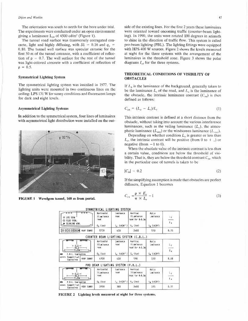
The orientation was south to north for the bore under trial. The experiments were conducted under an open environment giving a luminance L20 of 4500 cd/m2 (Figure 1).
The tunnel road surface was transversely corrugated concrete, light and highly diffusing, with Sl = 0.16 and q0 = 0.10. The tunnel wall surface was specular ceramic for the first 50 m of the tunnel entrance, with a coefficient of reflection of p = 0.7 . The wall surface for the rest of the tunnel was light-colored concrete with a coefficient of reflection of p = 0.5.
Symmetrical Lighting System
The symmetrical lighting system was installed in 1977. The lighting units were mounted in two continuous lines on the ceiling: LPS 131 W for sunny conditions and fluorescent lamps for dark and night levels.
Asymmetrical Lighting Systems
In addition to the symmetrical system, four lines of luminaires with asymmetrical light distribution were installed on the out-
FIGURE 1 Wevelgem tunnel, 160 m from portal.
47
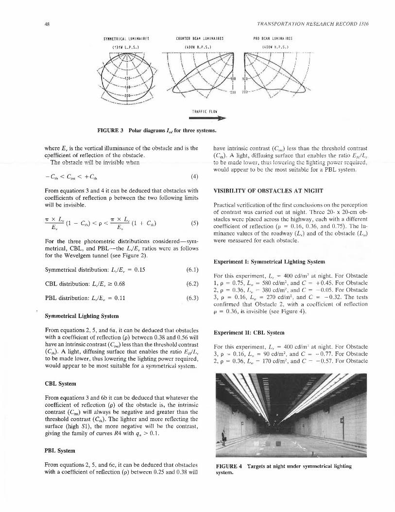
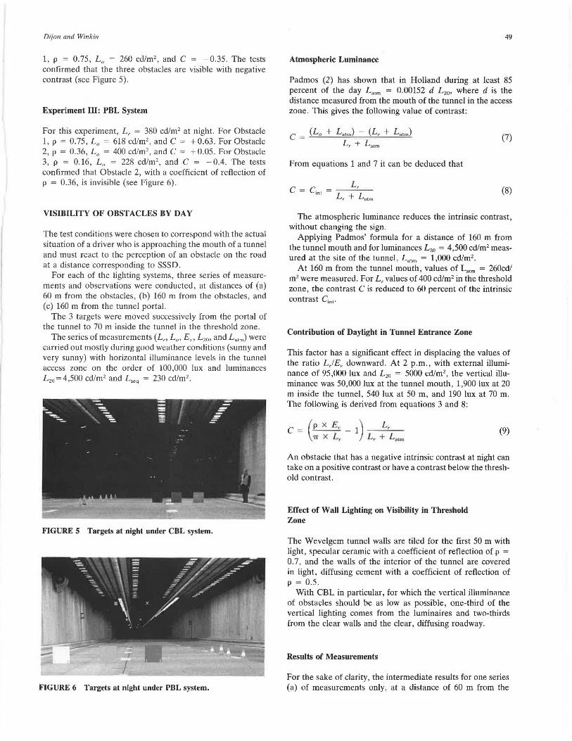
side of the existing lines. For the first 2 years these luminaires were oriented toward oncoming traffic (counter-beam lighting). In 1990, the units were rotated 180 degrees in azimuth to shine in the direction of traffic flow . This system is called pro-beam lighting (PBL). The lighting fittings were equipped with HPS 400 W sources. Figure 2 shows the levels measured at night for the three systems with the arrangement of the luminaires in the threshold zone. Figure 3 shows the polar diagrams led for the three systems.
THEORETICAL CONDITIONS OF VISIBILITY OF OBSTACLES
If Lb is the luminance of the background, generally taken to be the luminance L , of the road, and L 0 is the luminance of the obstacle, the intrinsic luminance contrast ( C;,,,) is then defined as follows:
C'"' = (L 0 - L,)IL, (1)
This intrinsic contrast is defined at a short distance from the obstacle, without taking into account the various interference luminances, such as the veiling luminance (L..), the atmospheric luminance (L.,,n) or the windscreen luminance (L,,",.).
Depending on whether condition L0 is greater or less than L,, the intrinsic contrast will be positive (from 0 to + J or negative (from -1 to 0).
When the absolute value of the intrinsic contrast is less than a certain value, conditions are below the threshold of visibility. That is, they are below the threshold contrast C,h. which in the particular case of tunnels is taken to be
(2)
If the simplifying assumption is made that obstacles are perfect diffusers, Equation 1 becomes
C =p x £ ,. -1 in • L 1T X r
(3)
SYMMETRICAL LIGHTING SYSTEM • • • I --- Horlzont1L LutlOIO(! Vertical Valls
<> l1S 1l1V ' i LLU1lnnte rnd lllutln1n<1 LUii nance Lr
0 FLUO !10V. road ro•d tor H•O.l1 -...... • sunm m. [' - Eh (Lux) L (cd/1 • l E, (lurl L, (cd/1')
loolooJ::>ooot vmsum 5700 400 1400 510 0 .15
COUNTER BEAM LIGHTING SYSTEH ( C. B. L.) Horizontal lu1lnance Vert I ca L Valls i llu1in;iince road i llU1lunce lu1inance Lr road road tor H•O.l1
'· E (Lux) L (cd/1' l E, (Luxl L, (cd/1')
4900 400 590 510 0. 68
PRO BEAH LIGHTING SYSTEM ( P. B. L.) Horizontal lu1lnance Verlical Valls i llutiunce rod lllu1inance LU1funce Lr road ro•d for H•O. l1
E, E; (Lux) L, (cd/1' ) E, (Lux) L, (cd/1')
3900 380 3400 395 0 .11
FIGURE 2 Lighting levels measured at night for three systems.
48 TRANSPORTATION RESEARCH RECORD 1316
SYKKETRICAL LUKINAIRES
(1l1V L.P.S.)
COUNTER BEAM LUK I NA I RES PRO BEAK LUMINAIRES
(IOOW H.P.S.) (IOOV H.P.S.)
TRAFF I ( FLOW
FIGURE 3 Polar diagrams led for three systems.
where Ev is the vertical illuminance of the obstacle and is the c9efficient of reflection of the obstacle.
The obstacle 'Nill be invisible '.vhen
(4)
From equations 3 and 4 it can be deduced that obstacles with coefficients of reflection p between the two following limits will be invisible.
(5)
For the three photometric distributions considered-symmetrical, CBL, and PBL-the L/Ev ratios were as follows for the Wevelgem tunnel (see Figure 2).
Symmetrical distribution: L,/Ev = 0.15
CBL distribution: L,/Ev ~ 0.68
PBL distribution: L,!Ev = 0.11
Symmetrical Lighting System
(6.1)
(6 .2)
(6.3)
From equations 2, 5, and 6a, it can be deduced that obstacles with a coefficient of reflection (p) between 0.38 and 0.56 will have an intrinsic contrast ( C;nr) less than the threshold contrast ( c,h). A light, diffusing surface that enables the ratio EH/ L, to be made lower, thus lowering the lighting power required, would appear to be most suitable for a symmetrical system.
CBL System
From equations 3 and 6b it can be deduced that whatever the coefficient of reflection (p) of the obstacle is, the intrinsic contrast ( C;n,) will always be negative and greater than the threshold contrast ( C,h). The lighter and more reflecting the surface (high Sl), the more negative will be the contrast, giving the family of curves R4 with q0 > 0.1.
PBL System
From equations 2, 5, and 6c, it can be deduced that obstacles with a coefficient of reflection (p) between 0.25 and 0.38 will
have intrinsic contrast ( C;".) less than the threshold contrast (C,h). A light, diffusing surface that enables the ratio ENIL,
would appear to be the most suitable for a PBL system.
VISIBILITY OF OBSTACLES AT NIGHT
Practical verification of the first conclusions on the perception of contrast was carried out at night. Three 20- x 20-cm obstacles were placed across the highway, each with a different coefficient of reflection (p = 0.16, 0.36, and 0.75). The luminance values of the roadway (L,) and of the obstacle (L0 )
were measured for each obstacle .
Experiment I: Symmetrical Lighting System
For this experiment, L, = 400 cd/m2 at night . For Obstacle 1, p = 0.75, L
0 = 580 cd/m2, and C = + 0.45. For Obstacle
2, p = 0.36, L0
= 380 cd/m2 , and C = -0.05. For Obstacle 3, p = 0.16, L 0 = 270 cd/m2
, and C = -0.32. The tests confirmed that Obstacle 2, with a coefficient of reflection p = 0.36, is invisible (see Figure 4).
Experiment II: CBL System
For this experiment , L, = 400 cd/m2 at night. For Obstacle 3, p = 0.16, L 0 = 90 cd/m2 , and C = -0.77. For Obstacle 2, p = 0.36, L
0 = 170 cd/m2, and C = -0.57. For Obstacle
FIGURE 4 Targets at night under symmetrical lighting system.
Dijon and Winkin
1, p = 0.75, L 0 = 260 cd/m2 , and C = -0.35. The tests confirmed that the three obstacles are visible with negative contrast (see Figure 5).
Experiment III: PBL System
For this experiment, L, = 380 cd/m2 at night. For Obstacle 1, p = 0.75, L 0 = 618 cd/m2
, and C = +0.63. For Obstacle 2, p = 0.36, L0 = 400 cd/m2
, and C = + 0.05. For Obstacle 3, p = 0.16, L 0 = 228 cd/m2 , and C = -0.4. The tests confirmed that Obstacle 2, with a coefficient of reflection of p = 0.36, is invisible (see Figure 6) .
VISIBILITY OF OBSTACLES BY DAY
The test conditions were chosen to correspond with the actual situation of a driver who is approaching the mouth of a tunnel and must react to the perception of an obstacle on the road at a distance corresponding to SSSD.
For each of the lighting systems, three series of measurements and observations were conducted, at distances of (a) 60 m from the obstacles, (b) 160 m from the obstacles, and (c) 160 m from the tunnel portal.
The 3 targets were moved successively from the portal of the tunnel to 70 m inside the tunnel in the threshold zone.
The series of measurements (L,, L 0 , E,., L 20 , and L.,m) were carried out mostly during good weather conditions (sunny and very sunny) with horizontal illuminance levels in the tunnel access zone on the order of 100,000 lux and luminances L20 =4,500 cd/m2 and Lseq = 230 cd/m2
•
FIGURE 5 Targets at night under CBL system.
FIGURE 6 Targets at night under PBL system.
49
Atmospheric Luminance
Padmos (2) has shown that in Holland during at least 85 percent of the day L.,m = 0.00152 d L 20 , where d is the distance measured from the mouth of the tunnel in the access zone. This gives the following value of contrast:
c = (Lo + L.,m) - (L, + L.,m)
L, + L.,m
From equations 1 and 7 it can be deduced that
L, C = Cin• = --'--
L, + L.,m
(7)
(8)
The atmospheric luminance reduces the intrinsic contrast, without changing the sign.
Applying Padmos' formula for a distance of 160 m from the tunnel mouth and for luminances L 20 = 4,500 cd/m2 measured at the site of the tunnel, L.,m = 1,000 cd/m2•
At 160 m from the tunnel mouth, values of L.,m = 260cd/ m2 were measured. For L, values of 400 cd/m2 in the threshold zone, the contrast C is reduced to 60 percent of the intrinsic contrast Cini'
Contribution of Daylight in Tunnel Entrance Zone
This factor has a significant effect in displacing the values of the ratio LJEv downward. At 2 p.m., with external illuminance of 95,000 lux and L 20 = 5000 cd/m2 , the vertical illuminance was 50,000 lux at the tunnel mouth, 1,900 lux at 20 m inside the tunnel, 540 lux at 50 m, and 190 lux at 70 m. The following is derived from equations 3 and 8:
C - (p x £ ,, - 1) L, - 'IT x L, L, + L, ... ,
(9)
An obstacle that has a negative intrinsic contrast at night can take on a positive contrast or have a contrast below the threshold contrast.
Effect of Wall Lighting on Visibility in Threshold Zone
The Wevelgem tunnel walls are tiled for the first 50 m with light, specular ceramic with a coefficient of reflection of p = 0.7, and the walls of the interior of the tunnel are covered in light, diffusing cement with a coefficient of reflection of p = 0.5.
With CBL in particular, for which the vertical illumin:mr.r. of obstacles should be as low as possible, one-third of the vertical lighting comes from the luminaires and two-thirds from the clear walls and the clear, diffusing roadway.
Results of Measurements
For the sake of clarity, the intermediate results for one series (a) of measurements only, at a distance of 60 m from the
50
obstacles, are given here. The differences in the results of the series are due entirely to L.,m increasing from series (a) to (c).
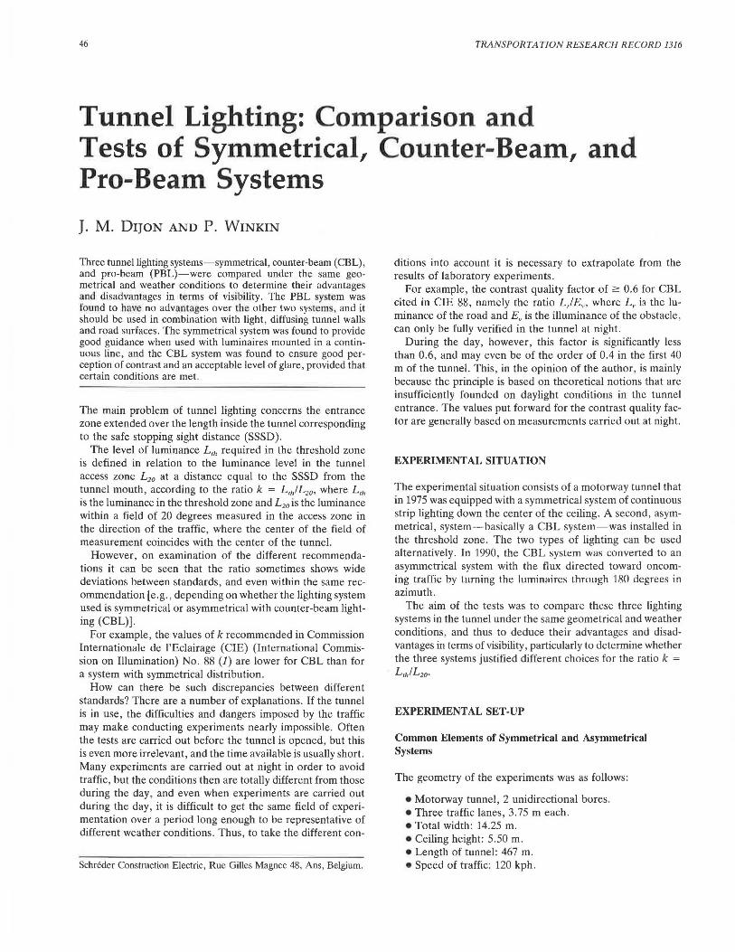
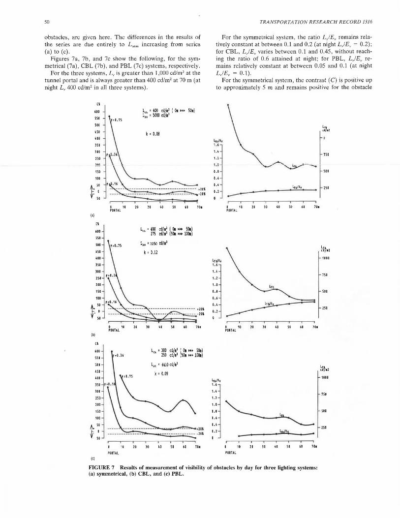
Figures 7a, 7b, and 7c show the following , for the symmetrical (7a), CBL (7b), and PBL (7c) systems, respectively.
For the three systems, L, is greater than 1,000 cd/m2 at the tunnel portal and is always greater than 400 cd/m2 at 70 m (at night L, 400 cd/m2 in all three systems).
(a)
(I
600
550
500
ISO
100
m lOO
250
Cl
IDO
550
500
450
\GO
m lOO
m 200
110
1GO
~ s: f 50
(b)
Cl
600
550
500
ISO
100
350
JOO
250
200
150
100
1+ 5: f 50
(c)
L,. • 400 cd/11 I ill ••• 50.) L,0 • 5000 cd/11
k ' 0.08
1~0-. 1~ - ~-------- ---------- .m ---- ----------_ ---------- -201
T r I T 0 10 20 lO 10 50 60 70. PORTAL
0 10 20 PORTAL
•0.36
10 20
PORTAL
L,. • 400 cd/11 ! Ill »• 50.1 275 cd/11 SOI »• 100.
L,0 • 3250 cd/11
k ' 0.12
lO
30
50 iO 701
L,. • 380 cd/11 ! Ill •» 50.1 250 cd/11 50. »• 100.
L,0 • rn.o cd/11
k ' 0.09
- ..... ..---~,,,._..,,zOI ------ - ------ -20I
10 50 60 701
TRANSPORTATION RESEARCH RECORD 1316
For the symmetrical system, the ratio L,!Ev remains relatively constant at between 0.1 and 0.2 (at night L,/ Ev = 0.2); for CBL, L,!Ev varies between 0.1 and 0.45, without reaching the ratio of 0.6 attained at night; for PBL, L,!Ev remains relatively constant at between 0.05 and 0.1 (at night L,IEV = 0.1).
For the symmetrical system, the contrast ( C) is positive up to approximately 5 m and remains positive for the obstacle
lo/I• u 1.1
1. 2
l.C
0.1
0.6
0. 1
0.2
0
lth/ly I . I
1.1
1.2
1.0
0.1
0.6
0.1
0.2
lo/I, 1.6
1.1
1. 2
1.0
0.1
0.6
0.1
0.2
0 10 20 lO PORTAL
0 10 20 30 PORTAL
10 20 lO
PORTAL
10 50 60 701
10 50 60 701
-10 50 iO 701
750
500
250
Ln cd712
1000
750
500
250
mo
750
500
m
FIGURE 7 Results of measurement of visibility of obstacles by day for three lighting systems: (a) symmetrical, (b) CBL, and (c) PBL.
Dijon and Winkin
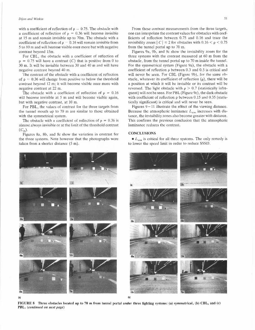
with a coefficient of reflection of p = 0. 75. The obstacle with a coefficient of reflection of p = 0.36 will become invisible at 15 m and remain invisible up to 70m. The obstacle with a coefficient of reflection of p = 0.16 will remain invisible from 5 to 10 m and will become visible once more but with negative contrast beyond 15m.
For CBL, the obstacle with a coefficient of reflection of p = 0.75 will have a contrast (C) that is positive from 0 to 30 m. It will be invisible between 30 and 40 m and will have negative contrast beyond 40 m.
The contrast of the obstacle with a coefficient of reflection of p = 0.36 will change from positive to below the threshold contrast beyond 12 m; it will become visible once more with negative contrast at 22 m.
The obstacle with a coefficient of reflection of p = 0.16 will become invisible at 5 m and will become visible again, but with negative contrast, at 10 m.
For PBL, the values of contrast for the three targets from the tunnel mouth up to 70 m are similar to those obtained with the symmetrical system .
The obstacle with a coefficient of reflection of p = 0.36 is almost always invisible or at the limit of the threshold contrast (C,h).
Figures 8a, 8b, and 8c show the variation in contrast for the three systems. Note however that the photographs were taken from a shorter distance (5 m).
(
-- - .
(a)
51
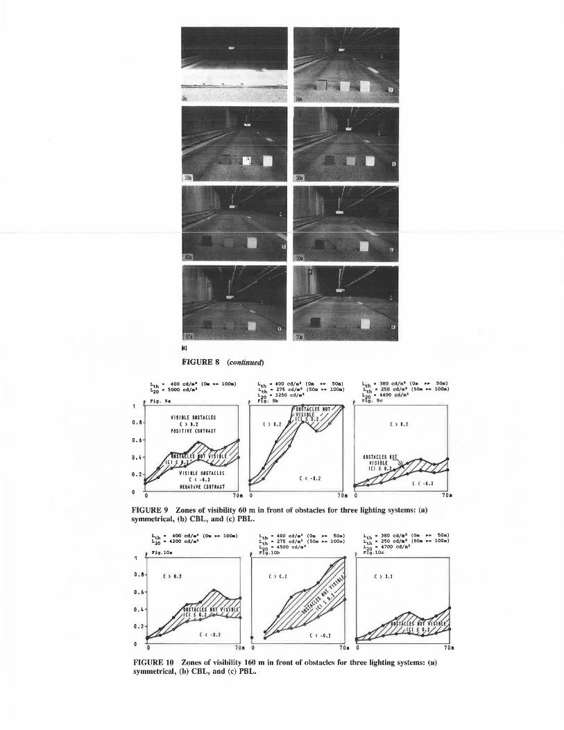
From these contrast measurements from the three targets, one can interpolate the contrast values for obstacles with coefficients of reflection between 0.75 and 0.16 and trace the invisibility zones I CI s 2 for obstacles with 0.16 < p < 0. 75 from the tunnel portal up to 70 m.
Figures 9a, 9b, and 9c show the invisibility zones for the three systems with the contrast measured at 60 m from the obstacle, from the tunnel portal up to 70 m inside the tunnel. For the symmetrical system (Figure 9a), the obstacle with a coefficient of reflection p between 0.3 and 0.5 is critical and will never be seen. For CBL (Figure 9b), for the same obstacle, whatever its coefficient of reflection (p), there will be a position at which it will be invisible or its contrast will be reversed . The light obstacle with p > 0.7 (statistically infrequent) will not be seen . For PBL (Figure 9c), the dark obstacle with coefficient of reflection p between 0.15 and 0.35 (statistically significant) is critical and will never be seen.
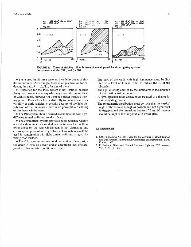
Figures 9 -11 illustrate the effect of the viewing distance. Because the atmospheric luminance L""" increases with distance , the invisibility zones also become greater with distance. This confirms the previous conclusion that the atmospheric luminance reduces the contrast.
CONCLUSIONS
• L 0 ,m is critical for all three systems. The only remedy is to lower the speed limit in order to reduce SSSD.
(b)
FIGURE 8 Three obstacles located up to 70 m from tunnel portal under three lighting systems: (a) symmetrical, (b) CBL, and (c) PBL. (continued on next page)
0.1
0.6
0.4
0.2
-!
~-=-~- -
(c)
FIGURE 8 (continued)
Lth • -400 cd/• 1 (0. •• 100.) Lio • sooo cd/•1
P'ig . 9a
VISllLE DISTACLES ( ) 1.2
IOSITIVE UITIAST
IEUTIYE CDITIAST
Lth • 390 cd/a> (Om •• 50•) 1.th • 250 cd/•' (50. •• 100.) L20 • 4400 cd/•1
Plig . 9c
( > O.l
FIGURE 9 Zones of visibility 60 m in front of obstacles for three lighting systems: (a) symmetrical, (b) CBL, and (c) PBL.
0. I
0. 6
0.4
0.2
Lth • 400 cd/• 11 (O. •• 100.) L20 • 4200 cd/• 11
Fig.10a
c ) •• ,
Lth • 380 ed/m 1 {Om .... SOa) Lth • 250 ed/m.1 (50m •• 100m) Lzo • 4700 cd/ma Fig. lOc
() 0.2
FIGURE 10 Zones of visibility 160 m in front of obstacles for three lighting systems: (a) symmetrical, (b) CBL, and (c) PBL.
Dijon and Winkin 53
Lth • 400 cd/• 1 (0. •• 100.) L20 • 4500 cd/•1
Lth • 400 cd/•8 (0. •• 50a) Lth • 275 cd/•1 (50m •• 100a) L20 • 5000 cd/al
p Fig . llb P'ig . 11•
0. 8 ( > 1.1 c > l.l c > 1.2
0.6
o.~
0.2
0 Porhl A
70. O Portal A
Portal
FIGURE 11 Zones of visibility 160 m in front of tunnel portal for three lighting systems: (a) symmetrical, (b) CBL, and (c) PBL.
• There are, for all three systems, invisibility zones of similar importance . Accordingly, there is no justification for reducing the ratio k = L,h!L20 for any of them.
• Preference for the PBL system is not justified because the system does not have any advantages over the symmetrical or CBL systems. Moreover, it demands higher installed lighting power. Dark obstacles (statistically frequent) have poor visibility as dark vehicles, especially because of the light distribution of the luminaires there is no perceptible flickering on the back windscreens.
• The PBL system should be used in combination with light, diffusing tunnel walls and road surfaces.
• The symmetrical system provides good guidance when it is used with luminaires mounted in a continuous line. A flickering effect on the rear windscreens is not distracting and ensures perception of moving vehicles. This system should be used in combination with light tunnel walls and a light, diffusing road surface.
•The CBL system ensures good perception of contrast, a reduction in installed power, and an acceptable level of glare , provided that certain conditions are met:
- The part of the walls with high luminance must be limited to a level of 1 m in order to reduce the Ev of the obstacles.
- The light intensity emitted by the luminaires in the direction of the traffic must be limited.
-A light, specular road surface must be used to enhance installed lighting power.
-The photometric distribution must be such that the vertical angle of the beam is as high as possible but not higher that 56 degrees, and the intensities between 70 and 90 degrees should be kept as low as possible to avoid glare.
REFERENCES
1. CIE Publication No. 88: Guide for the Lighting of Road Tunnels and Underpasses. International Committee on Illumination, Paris, France, 1990.
2. P. Padmos . Glare and Tunnel Entrance Lighting. CIE Journal, Vol. 3, No. 1, 1984.