Embed Size (px)
Citation preview
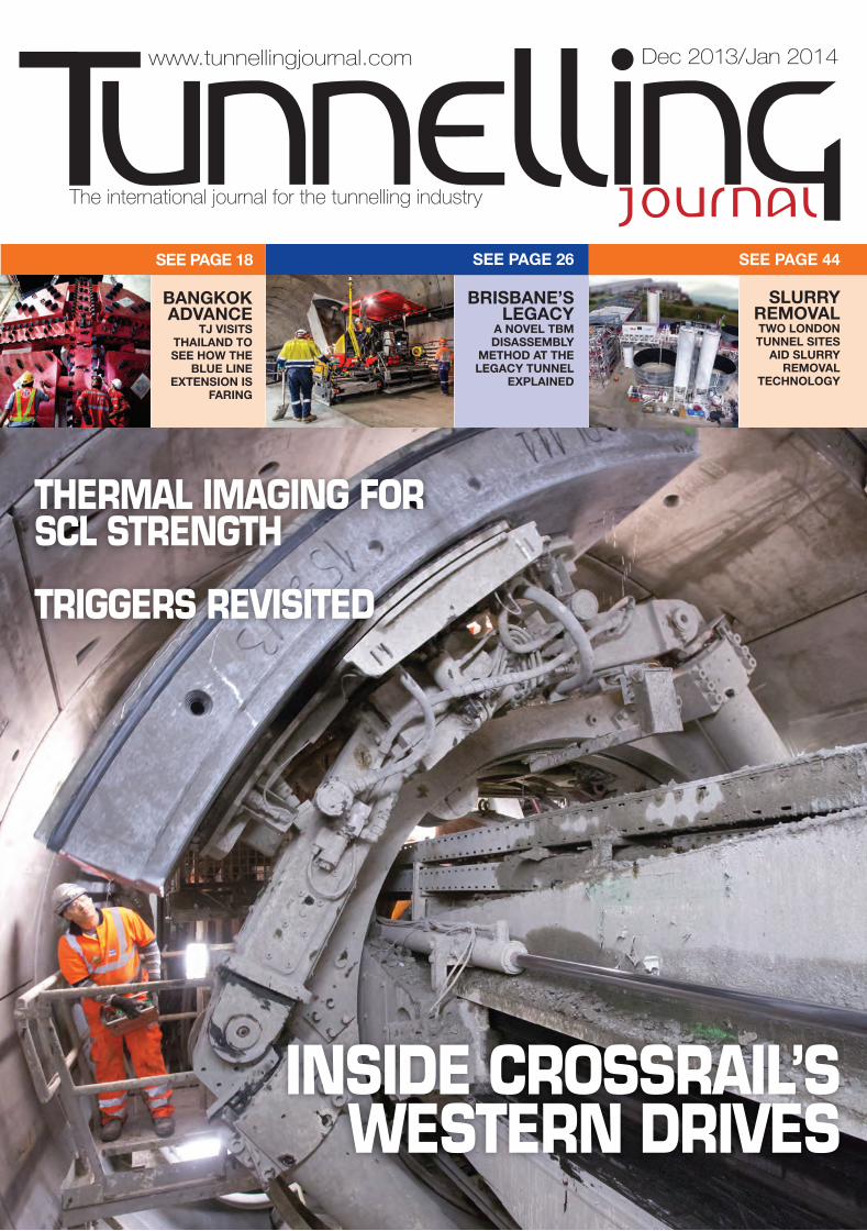
BANGKOKADVANCE
TJ VISITS THAILAND TO SEE HOW THE
BLUE LINEEXTENSION IS
FARING
SEE PAGE 44SEE PAGE 26SEE PAGE 18
BRISBANE’SLEGACY
A NOVEL TBMDISASSEMBLY
METHOD AT THELEGACY TUNNEL
EXPLAINED
SLURRYREMOVALTWO LONDONTUNNEL SITES
AID SLURRYREMOVAL
TECHNOLOGY
journalTunnelling
The international journal for the tunnelling industry
www.tunnellingjournal.com Dec 2013/Jan 2014
INSIDE CROSSRAIL’S WESTERN DRIVES
THERMAL IMAGING FORSCL STRENGTH
TRIGGERS REVISITED
THAMES WATER’S LEE TUNNEL in the UK’sEast London, with its Slurry TBM driven8.88m diameter, 6,904m length and itsgeology of more than 98% in chalk, is a realchallenge in terms of spoil treatment. Thetotal volume of the chalk slurry afterseparation of the �ints (5 to 25%, average15%) represents more than 1,200,000m 3 ofliquid slurry. In such geology, where 95% ofthe solids could be transformed into extra-�nes, well below the cut o� point forcyclones or centrifuges, several method havebeen tried in the past to facilitate the disposalof the spoils, but none met the requirementsof the contractor, both in terms of costs and�nal result. This article will describe themethods and results achieved by the MorganSindall/Vinci Construction GrandsProjets/Bachy Soletanche Joint Venture MVBin reaching a consistency of more than 75%solids by weight, and thus drasticallyreducing the volume of spoils thereby easingtheir disposal.
The article will also give an overview of theresults obtained on another tunnel site insimilar geology in London, the CrossrailThames Tunnel, being constructed by theHochtief/Murphy Joint Venture HMJV. Aftertheir success in the award winning CTRL 320tunnel, where the discharge of thecentrifuges was mixed with cement beforeplacement, HMJV accepted a re-thinking ofits excess mud treatment method, havingbeen convinced by the argument in favour of�lter-presses enabling them to use analternative approach to slurry management.
The two tunnel sitesThe Lee Tunnel is part of a scheme to storeand send to treatment the sewage andrainwater from London, which presentlyover�ows into the River Thames. The 6.9kmlong Lee Tunnel runs through East London,and will eventually carry sewage fromLondon's largest combined sewer over�owfrom the Abbey Mills Pumping Station inStratford to the Beckton Sewage TreatmentWorks (STW) in Newham. The tunnel worksstarted in February 2012, and the entirescheme is expected to be completed in 2015.
The 2.6km long twin tubes for the ThamesTunnel is the only Crossrail route whichcrosses the River Thames. It is also the onlyslurry shield TBM of this project, because of
the chalk and Thanet sand encounteredalong its alignment, elsewhere EPB machinesrun in London clay, sand and gravel. Boringstarted in October 2012, and is due to becompleted early 2014.
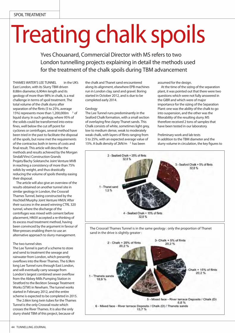
Geology The Lee Tunnel runs predominantly in theSeaford Chalk formation, with a small sectionof overlaying �ne clayey Thanet sands. ThisChalk consists of white, sometimes light grey,low to medium dense, weak to moderatelyweak chalk, with layers of �ints ranging from5 to 25%, with an expected average value of15%. A bulk density of 2kN/m 3 has been
assumed for the design. At the time of the sizing of the separation
plant, it was pointed out that there were twoquestions which were not fully answered inthe GIBR and which were of majorimportance for the sizing of the SeparationPlant: one was the ability of the chalk to gointo suspension, and the other was the�lterability of the resulting slurry. MStherefore received 2 tons of samples thathave been tested in our laboratory.
Preliminary work and lab testsIn addition to the TBM diameter and theslurry volume in circulation, the key �gures to
44 TUNNELLING JOURNAL
Yves Chouanard, Commercial Director with MS refers to twoLondon tunnelling projects explaining in detail the methods usedfor the treatment of the chalk spoils during TBM advancement
SPOIL TREATMENT
Treating chalk spoils
The Crossrail Thames Tunnel is in the same geology : only the proportion of Thanetsand in the drive is slightly greater :
SPOIL TREATMENT
take in consideration for sizing the SlurryTreatment Plant are:• the boring speed in the di erent geologies,
giving the maximum instantaneous valuesof volumes and tonnages of solids to behandled
• the daily progress target, giving averagevalues of consumables (bentonite, water…)and volumes of spoils generated
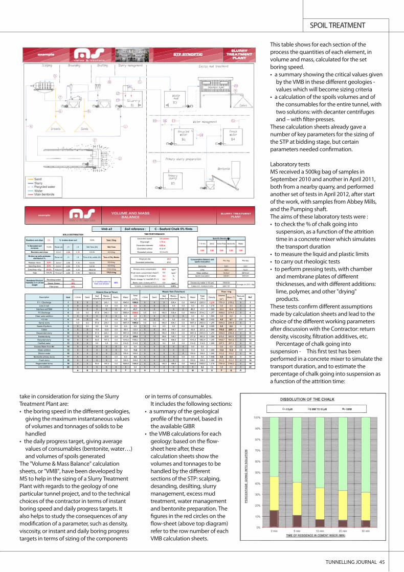
The "Volume & Mass Balance" calculationsheets, or "VMB", have been developed byMS to help in the sizing of a Slurry TreatmentPlant with regards to the geology of oneparticular tunnel project, and to the technicalchoices of the contractor in terms of instantboring speed and daily progress targets. Italso helps to study the consequences of anymod of a parameter, such as density,viscosity, or instant and daily boring progresstargets in terms of sizing of the components
or in terms of consumables.It includes the following sections:
• a summary of the geologicalpr of the tunnel, based inthe available GIBR
• the VMB calculations for eachgeology: based on the ow-sheet here after, thesecalculation sheets show thevolumes and tonnages to behandled by the di erentsections of the STP: scalping,desanding, desilting, slurrymanagement, excess mudtreatment, water managementand bentonite preparation. The
res in the red circles on thet (above top diagram)
refer to the row number of eachVMB calculation sheets.
This table shows for each section of theprocess the quantities of each element, involume and mass, calculated for the setboring speed.• a summary showing the critical values given
by the VMB in these di erent geologies -values which will become sizing criteria
• a calculation of the spoils volumes and ofthe consumables for the entire tunnel, withtwo solutions: with decanter centrifugesand – with r-presses.
These calculation sheets already gave anumber of key parameters for the sizing ofthe STP at bidding stage, but certainparameters needed co rmation.
Laboratory tests MS received a 500kg bag of samples inSeptember 2010 and another in April 2011,both from a nearby quarry, and performedanother set of tests in April 2012, after startof the work, with samples from Abbey Mills,and the Pumping shaft. The aims of these laboratory tests were :• to check the % of chalk going into
suspension, as a function of the attritiontime in a concrete mixer which simulatesthe transport duration
• to measure the liquid and plastic limits• to carry out rheologic tests• to perform pressing tests, with chamber
and membrane plates of di erentthicknesses, and with di erent additions:lime, polymer, and other "drying"products.
These tests co rm di erent assumptionsmade by calculation sheets and lead to thechoice of the di erent working parametersafter discussion with the Contractor: returndensity, viscosity, ltration additives, etc.
Percentage of chalk going intosuspension - This rst test has beenperformed in a concrete mixer to simulate thetransport duration, and to estimate thepercentage of chalk going into suspension asa function of the attrition time:
TUNNELLING JOURNAL 45
0,0 m 2,00 1,70
5,0% 5,6 m 2,00 1,70
0,0% 0,0 m 2,00 1,70
95,0% 105,9 m 2,00 1,70 80,0 kg/m3
100,0% 111,5 m 2,00 1,70 0,0 kg/m3
43,9 414,7 0,3 %
Revolving screen 0,0 %
Dewat. Screen 0,0 kg/m3
Filter-press 0,00%
Item > 6mm Sand Soil extra-fine
Recirc. extra-fine Bento. Water
Total
(m3/h)> 6mm Sand Soil
extra-fineRecirc.
extra-fine Bento. Water Total (T/h) Density
Volume
(m3)Mass (T) Tons per
day Ref.
1 X X X 240,1 0,0 1646,6 1886,8 X X X 636,4 0,0 1646,6 2283,0 1,210 1781,9 2156,2 X 12 X X X 0,0 0,0 0,0 0,0 X X X 0,0 0,0 0,0 0,0 1,210 0,0 0,0 X 23 X X X X X 41,7 41,7 X X X X X 41,7 41,7 1,000 39,4 39,4 X 34 3,6 0,0 67,9 240,1 0,0 1688,4 2000,0 9,5 0,0 180,0 636,4 0,0 1688,4 2514,2 1,257 1888,9 2374,5 X 45 X X X X X 0,0 0,0 X X X X X 0,0 0,0 1,000 0,0 0,0 0 56 3,6 X 0,0 0,1 0,0 0,6 4,2 9,5 X 0,1 0,2 0,0 0,6 10,3 2,433 4,0 9,7 233 67 0,0 0,0 67,9 240,1 0,0 1687,8 1995,8 0,0 0,0 180,0 636,1 0,0 1687,8 2503,9 1,255 1884,9 2364,8 X 78 X 0,0 0,0 0,0 0,0 0,0 0,0 X 0,0 0,0 0,0 0,0 0,0 0,0 0,000 0,0 0,0 0 89 X X 15,0 52,9 0,0 56,9 125,0 X X 39,6 140,1 0,0 56,9 237,2 1,898 118,0 224,1 5377 9
10 X X 67,9 240,1 0,0 1687,8 1995,8 X X 180,0 636,1 0,0 1687,8 2503,9 1,255 1884,9 2364,8 X 1011 X X 15,0 52,9 0,0 371,8 439,6 X X 39,6 140,1 0,0 371,8 551,5 1,255 415,2 520,9 X 1112 X X 53,0 187,2 0,0 1316,0 1556,2 X X 140,3 496,0 0,0 1316,0 1952,4 1,255 1469,7 1843,9 X 1213 X X 0,0 0,0 0,0 314,8 314,8 X X 0,0 0,0 0,0 314,8 314,8 1,000 297,3 297,3 X 1314 X X X X X 0,0 0,0 X X X X X 0,0 0,0 - 0,0 0,0 X 1415 X X X X X 15,8 15,8 X X X X X 15,8 15,8 1,000 14,9 14,9 358 1516 X X X X X 330,6 330,6 X X X X X 330,6 330,6 1,000 312,2 312,2 X 1617 X X X X 0,0 0,0 0,0 X X X X 0,0 0,0 0,0 1,048 0,0 0,0 0 1718 X X X X 0,0 330,6 330,6 X X X X 0,0 330,6 330,6 1,000 312,2 312,2 X 1819 X X 53,0 187,2 0,0 1646,6 1886,8 X X 140,3 496,0 0,0 1646,6 2283,0 1,210 1781,9 2156,2 X 1920 X X X X X X 0,9 X X X X X X 0,5 0,6 0,8 0,5 X 20
A B C D E F G H I J K L M N O P Q RLime addition
Excess Water from B6
Water addition
Dilution water
Bentonite-primary slurry
Fresh slurry
Regenerated slurry
Sands 63 -6mm
Cakes
Dessanded slurry
Excess slurry
Recycled slurry
Clarified water
Loss in soil
Interface soil/TBM
P2 Discharge
Clear water addition
> 6 mm
Sandy slurry
Volumic flow (m3/hour) Massic flow (Tons/hour) Flow / ring
Description
P.1.1 Discharge
Bento. conc. in slurry at P1.1 Excess dry matter (< 63 m) 169,8 t/hAverage on 24 h / day
24% % bento. in dewatered sands (item.8) Cakes incl. moisture & lime 224,1 t/h
Lime dosage in % of cakes Spoils evacuation 233,8 t 5610,9 t
Dewatered Product Humidity in % of wet
weight
8%% of clarified water for
fresh mud dillution 95%
Bento. dosage % / total MS (P1-1)
18%
12,2 t
Total 189,5 t/h 179,0 t/ring Fresh slurry concentration (Kg/m3) Water addition 14,9 m 357,6 m
Extra-fines <63 180,0 t/h 170,0 t/ring Primary slurry concentration Lime 0,5 t
Sand 63 -6mm 0,0 t/h 0,0 t/ring Bentonite 0,0 t 0,0 t
Rings per day 24,0 Consumables Balance and spoils evacuation Per ring Per day
Pebbles >6mm 9,5 t/h 8,9 t/ring Excavated meters/day 40,8
Broken up soils grainsize distribution % Excav vol h d Tons of dry solids (t/h) Tons of Dry Matter
2,65 2,65 2,50 1,00Boulders and chips 0,0 t/h 0,0 t/ring Excavated volume 111,5 m /h
Wet Tons Excavation diameter 8,88 m
Excavated surface 61,9 m2,65
% Saturated soil moisture 15,0% Excav vol h d Wet Tons (t/h)
Spécific Density ( s)
Ring length 1,70 m> 6 mm Sand Extra-fines Bentonite Water
SOILS DISTRIBUTION TBM PERFORMANCE
Boulders and chips 0% % broken down soil 100% Total / RingExcavation speed 3,0 cm/min
exampleSLURRY TREATMENT
PLANT
Vmb a3 Soil reference :
VOLUME AND MASS BALANCE
C - Seaford Chalk 5% flints
To maintain a safety margin, it was decided to consider for the sizing - the possibility that 100% of the chalk will come into solution, and - only5% of .
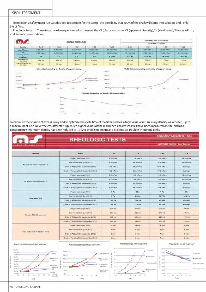
Rheologic tests - These tests have been performed to measure the VP (plastic viscosity), VA (apparent viscosity), Yv (Yield Value), Filtrates API ,at di erent concentrations:
To minimize the volume of excess slurry and to optimize the cycle time of the lter-presses, a high value of return slurry density was chosen, up toa maximum of 1.42. Nevertheless, after start-up, much higher values of the real mined chalk viscosities have been measured on site, and as aconsequence this return density has been reduced to 1.30, to avoid settlement and building up troubles in storage tanks.
SPOIL TREATMENT
46 TUNNELLING JOURNAL
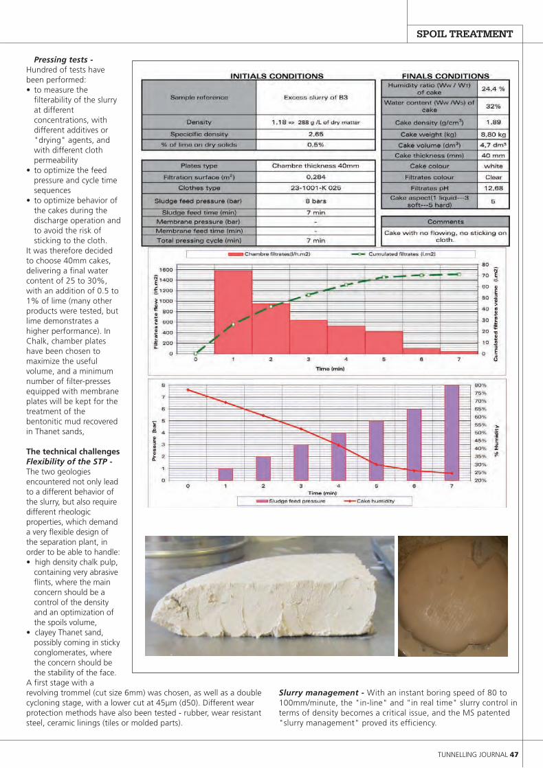
Pressing tests -Hundred of tests havebeen performed:• to measure the
filterability of the slurryat differentconcentrations, withdifferent additives or"drying" agents, andwith different clothpermeability
• to optimize the feedpressure and cycle timesequences
• to optimize behavior ofthe cakes during thedischarge operation andto avoid the risk ofsticking to the cloth.
It was therefore decidedto choose 40mm cakes,delivering a final watercontent of 25 to 30%,with an addition of 0.5 to1% of lime (many otherproducts were tested, butlime demonstrates ahigher performance). InChalk, chamber plateshave been chosen tomaximize the usefulvolume, and a minimumnumber of filter-pressesequipped with membraneplates will be kept for thetreatment of thebentonitic mud recoveredin Thanet sands,
The technical challengesFlexibility of the STP -The two geologiesencountered not only leadto a different behavior ofthe slurry, but also requiredifferent rheologicproperties, which demanda very flexible design ofthe separation plant, inorder to be able to handle:• high density chalk pulp,
containing very abrasiveflints, where the mainconcern should be acontrol of the densityand an optimization ofthe spoils volume,
• clayey Thanet sand,possibly coming in stickyconglomerates, wherethe concern should bethe stability of the face.
A first stage with arevolving trommel (cut size 6mm) was chosen, as well as a doublecycloning stage, with a lower cut at 45μm (d50). Different wearprotection methods have also been tested - rubber, wear resistantsteel, ceramic linings (tiles or molded parts).
Slurry management - With an instant boring speed of 80 to100mm/minute, the "in-line" and "in real time" slurry control interms of density becomes a critical issue, and the MS patented"slurry management" proved its efficiency.
SPOIL TREATMENT
TUNNELLING JOURNAL 47
SPOIL TREATMENT
48 TUNNELLING JOURNAL
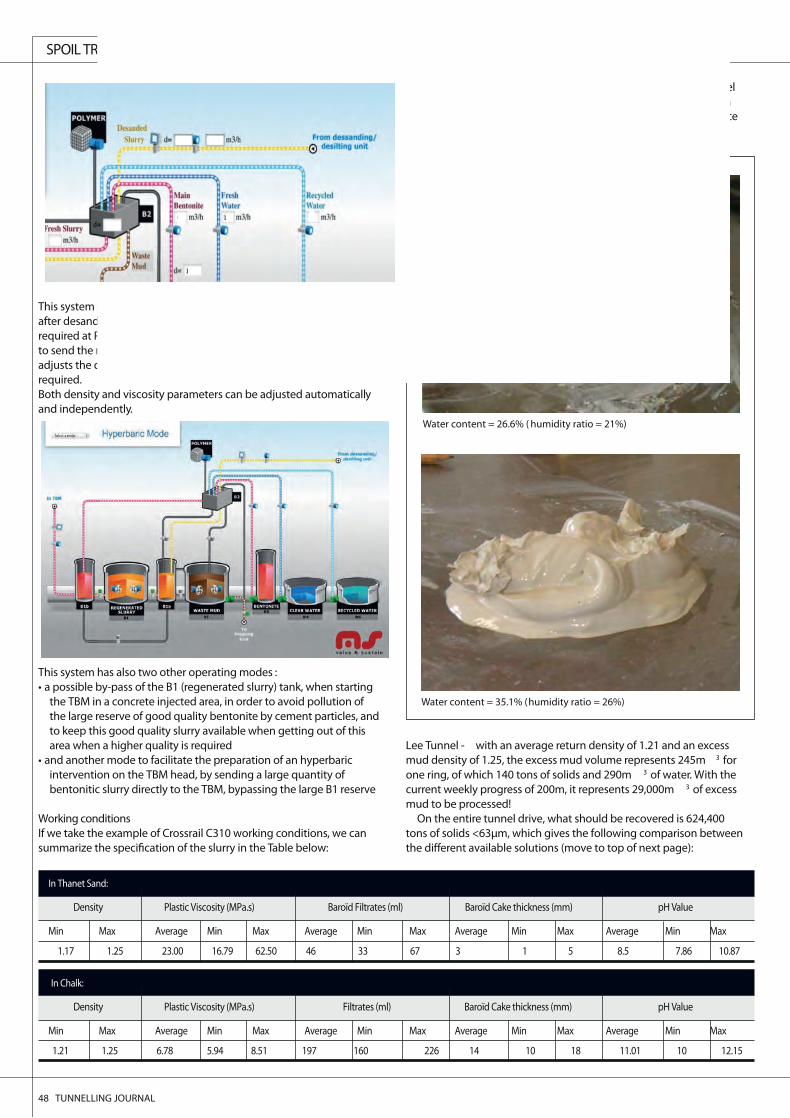
This system measures (F1) the incoming slurry volume and densityafter desanding & desilting, and compares these values to the settingsrequired at P1 pump. It opens accordingly the monitored valve MV1to send the right the volume of excess slurry to waste mud tank, andadjusts the dilution water volume (F3) and Bentonite (F2) addition ifrequired.Both density and viscosity parameters can be adjusted automaticallyand independently.
This system has also two other operating modes :• a possible by-pass of the B1 (regenerated slurry) tank, when starting
the TBM in a concrete injected area, in order to avoid pollution ofthe large reserve of good quality bentonite by cement particles, andto keep this good quality slurry available when getting out of thisarea when a higher quality is required
• and another mode to facilitate the preparation of an hyperbaricintervention on the TBM head, by sending a large quantity ofbentonitic slurry directly to the TBM, bypassing the large B1 reserve
Working conditionsIf we take the example of Crossrail C310 working conditions, we cansummarize the ion of the slurry in the Table below:
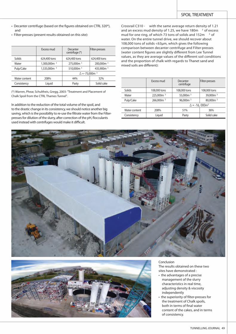
Excess mud treatment - This is the major challenge of this TunnelWork, which becomes even more challenging due to the fact that avery small di erence in the moisture content gives a huge di erencein the chalk spoil consistency and aspect:
Lee Tunnel - with an average return density of 1.21 and an excessmud density of 1.25, the excess mud volume represents 245m 3 forone ring, of which 140 tons of solids and 290m 3 of water. With thecurrent weekly progress of 200m, it represents 29,000m 3 of excessmud to be processed!
On the entire tunnel drive, what should be recovered is 624,400tons of solids <63µm, which gives the following comparison betweenthe di erent available solutions (move to top of next page):
In Thanet Sand:
Density Plastic Viscosity (MPa.s) Baroïd Filtrates (ml) Baroïd Cake thickness (mm) pH Value
Min Max Average Min Max Average Min Max Average Min Max Average Min Max
1.17 1.25 23.00 16.79 62.50 46 33 67 3 1 5 8.5 7.86 10.87
In Chalk:
Density Plastic Viscosity (MPa.s) Filtrates (ml) Baroïd Cake thickness (mm) pH Value
Min Max Average Min Max Average Min Max Average Min Max Average Min Max
1.21 1.25 6.78 5.94 8.51 197 160 226 14 10 18 11.01 10 12.15
Water content = 26.6% ( humidity ratio = 21%)
Water content = 35.1% (humidity ratio = 26%)
SPOIL TREATMENT
TUNNELLING JOURNAL 49
• Decanter centrifuge (based on the �gures obtained on CTRL 320*),and
• Filter-presses (present results obtained on this site):
In addition to the reduction of the total volume of the spoil, and to the drastic change in its consistency, we should notice another bigsaving, which is the possibility to re-use the �ltrate water from the Filter-presses for dilution of the slurry, after correction of the pH, �occulantsused instead with centrifuges would make it di�cult.
Crossrail C310 - with the same average return density of 1.21and an excess mud density of 1.25, we have 180m 3 of excessmud for one ring, of which 73 tons of solids and 152m 3 ofwater. On the entire tunnel drive, we should recover about108,000 tons of solids <63µm, which gives the followingcomparison between decanter centrifuge and Filter-presses(water content �gures are slightly di�erent from Lee Tunnelvalues, as they are average values of the di�erent soil conditionsand the proportion of chalk with regards to Thanet sand andmixed soils are di�erent):
Excess mud Decanter Filter-pressescentrifuge (*)
Solids 624,400 tons 624,400 tons 624,400 tonsWater 1,300,000m 3 275,000m 3 200,000m 3
Pulp/Cake 1,535,000m 3 510,000m 3 435,900m 3
∆ = -75,000m 3
Water content 208% 44% 32%Consistency Liquid Pasty Solid cake
(*) Warren, Phear, Schultheis, Gregg, 2003: "Treatment and Placement ofChalk Spoil from the CTRL Thames Tunnel".
Excess mud Decanter Filter-pressescentrifuge
Solids 108,000 tons 108,000 tons 108,000 tonsWater 225,000m 3 55,000m 3 39,000m 3
Pulp/Cake 266,000m 3 96,000m 3 80,000m 3
∆ = -16, 000m3
Water content 208% 51% 36%Consistency Liquid Pasty Solid cake
ConclusionThe results obtained on these twosites have demonstrated :• the advantages of a precise
management of the slurrycharacteristics in real time,adjusting density & viscosityindependently
• the superiority of �lter-presses forthe treatment of Chalk spoils,both in terms of �nal watercontent of the cakes, and in termsof consistency.