Embed Size (px)
Citation preview

Operating Manual Translation of original instructions
D445476XA vers. 2.0
EN
Twister II

© 2015 SILCA S.p.A. - Vittorio Veneto
All rights reserved. No part of this publication may be reproduced or used in any form or by any means (photocopying, microfi lm or other) without the written permission of Silca S.p.A.
Edition: July 2017
Printed in Indiaby MINDA SILCA Engineering Ltd.Plot no.37, Toy City, GREATER NOIDA (U.P.) - 201308
IMPORTANT NOTE: in compliance with current regulations relating to industrial property, we hereby state that the trade-marks or trade names mentioned in our documentation are the exclusive property of authorized manufacturers of locks and users. manufacturers of locks and users.Said trade-marks or trade names are shown only for the purposes of information so that any lock for which our keys are made can be rapidly identi-fi ed.

INDEXGUIDE TO THE MANUAL ................................................................................................................... 1
GENERAL INTRODUCTION ............................................................................................................... 21 TRANSPORT ........................................................................................................................................4
1.1 PACKING ...................................................................................................................................4
1.2 TRANSPORT ..............................................................................................................................4
1.3 UNPACKING ...............................................................................................................................4
1.4 HANDLING THE MACHINE ........................................................................................................4
1.5 SAFETY ......................................................................................................................................4
2 MACHINE DESCRIPTION ....................................................................................................................5
3 WORKING PARTS ................................................................................................................................7
3.1 TECHNICAL DATA .....................................................................................................................8
3.2 ELECTRIC CIRCUIT ...................................................................................................................9
4 ACCESSORIES PROVIDED .............................................................................................................10
5 MACHINE INSTALLATION AND PREPARATION ..............................................................................11
5.1 CHECKING FOR DAMAGE ......................................................................................................11
5.2 ENVIRONMENTAL CONDITIONS ............................................................................................11
5.3 POSITIONING .........................................................................................................................11
5.4 DESCRIPTION OF WORK STATION .......................................................................................11
6 MACHINE REGULATION AND UTILIZATION ....................................................................................12
6.1 FITTING AND REGULATING THE TOOLS ..............................................................................12
6.2 CALIBRATION OF CUTTER AND TRACER ............................................................................13
7 CUTTING OPERATIONS ...................................................................................................................14
7.1 KEY CUTTING .........................................................................................................................14
7.2 CUTTING KEYS WITH KEY STOPS ........................................................................................14
7.3 CUTTING KEYS WITHOUT KEY STOPS ................................................................................15
7.4 INSERTING THE SPRING SYSTEM FOR DIMPLE KEYS ......................................................15
7.5 CUTTING LASER (SIDEWINDER ) TYPE KEYS .....................................................................15
7.6 CUTTING NARROW-BLADE LASER (SIDEWINDER) TYPE KEYS .................................... 167.7 CUTTING KEYS FOR FICHET .................................................................................................16
8 MAINTENANCE ..................................................................................................................................17
8.1 REPLACING THE BELT AND ADJUSTING TENSION .............................................................17
8.2 REPLACING THE LAMP .........................................................................................................18
8.3 CHECKING AND REPLACING THE FUSES ............................................................................18
8.4 REPLACING THE JAWS ON RIGHT-HAND CLAMP ...............................................................198.4.1 REPLACING LEFT JAW ................................................................................................198.4.2 REPLACING RIGHT JAW ..............................................................................................19
9 DISPOSAL ..........................................................................................................................................20
10 AFTER-SALES SERVICE ..................................................................................................................21
10.1 HOW TO REQUEST SERVICE ................................................................................................21


Operating manual - English Twister II
Copyright Silca S.p.A. 2017 1
GUIDE TO THE MANUAL This manual has been produced to serve as a guide for users of the TWISTER II key-cutting machine. Read it carefully; it is essential if you wish to operate your machine safely and effi ciently.
ConsultationThe contents of the manual are divided into sections relating to:- Transport and handling ...............................................................................................Ch. 1- Description of machine and safety devices ................................................................Ch. 2-3-4- Proper use of machine ...............................................................................................Ch. 5-6-7- Maintenance ...............................................................................................................Ch. 8-9-10
Technical termsCommon technical terms are used in this manual. To assist those with little experience of key cutting, below is an illustration of the terms used for the different parts of keys.
DIMPLE KEYSkeys with holes of different dimensions,
depths, positions and shapes
LASER (SIDEWINDER) TYPE KEY LASER is the name given to the special sidewinder milled keys
Fig. 1
1) Head 5) Tip
2) Rim 6) Edge
3) Shoulder Stop 7) Cuts
4) Stem

Operating manual - English Twister II
Copyright Silca S.p.A. 20172
GENERAL INTRODUCTIONThe TWISTER II key-cutting machine has been designed according to CE specifi cations. From the design stage risks for the operator have been eliminated in all areas: transport, key- cutting, regulation and maintenance.Other risks have been eliminated by the use of protective devices for the operator.The protective devices used are designed not to provoke further risks and, above all, they cannot be ignored unless deliberately cut out. They do not hinder visibility of the work area.A special adhesive label is attached to the machine warning the operator to use goggles during the cutting operations, and this is strongly recommended in this manual.The material used in the manufacture of this machine and the components employed during use of the machine are not dangerous and their use complies with standards.
UseThe TWISTER II must be installed and used as specifi ed by the manufacturer.The TWISTER II key-cutting machine must be used only by skilled personnel (professional use).The key-cutting machine is designed for use on business or industrial premises (e.g. hardware shops, key cutting centers, etc...).If the key-cutting machine is used differently or for purposes different from those described in this manual, the customer will forego any rights he may have over the Company. Furthermore, unforeseen danger to the operator or any third parties may arise from incorrect use of the machine.Negligence in the use of the machine or failure on the part of the operator to observe the instructions given in this manual are not covered by the guarantee and the manufacturer declines all responsibility in such cases.
IT IS OBLIGATORY to read the manual carefully before using the machine.
Further RisksThere are no further risks arising from the use of the machine.
Protection and safety precautions for the operatorThe TWISTER II key-cutting machine is built entirely to CE standards. The operations for which it has been designed are easily carried out at no risk to the operator.The adoption of general safety precautions (wearing protective goggles) and observation of the instructions provided by the manufacturer in this manual eliminate all human error, unless deliberate. The TWISTER II key-cutting machine is designed with features which make it completely safe in all of its parts and operation.• Power supplyThe key-cutting machine is powered by electricity supplied through a separate grounded plug.• Start-upThe machine is turned on by means of the master switch located on the left-hand side. The switch has a safety function that prevents untimely start-up when voltage returns after a power outage.• OperationThe machine is started up by means of a motor switch.• IlluminationThe work area is illuminated by a lamp which operates when the machine is switched on with the master switch.• MaintenanceThe operations to regulate, service, repair and clean the machine have been devised in the simplest and safest way possible. There is no danger of removable parts being re-placed wrongly or unsafely.

Operating manual - English Twister II
Copyright Silca S.p.A. 2017 3
• Machine identifi cationThe TWISTER II key-cutting machine is provided with an identifi cation label which shows the serial number (Fig. 2).
Fig. 2
(*) see chap.9 DISPOSAL.

Operating manual - English Twister II
Copyright Silca S.p.A. 20174
1 TRANSPORTThe TWISTER II key-cutting machine is easily transported and is not dangerous to handle. The packed machine can be carried by two persons.
1.1 PACKING The packing used for the TWISTER II guarantees that the machine will travel safely without danger of damage to it or its components. The packing comprises two shells, lower and upper in expanded plastic in the machine is wrapped.A strong outer cardboard box, the measurements of which can be seen in Fig. 3 and the plastic wrapping protect the machine even over a long period of storage.Note: keep the packing and use it every time the machine must be transported.
Fig. 3
Keep dry Handle with care Up
1.2 TRANSPORTSymbols are printed on the outside of the cardboard box to give instructions and warnings for transportation.Use of the packing box whenever the machine is transported will avoid knocks or bumps which could cause damage.
1.3 UNPACKINGTo remove the machine from the packing box:1) Cut the straps with scissors and remove.2) Open the box without damaging it so that it may be used again (e.g. shipping to the manufacturer for repairs or
servicing).3) Check the contents of the box, which should comprise:
1 TWISTER II key-cutting machine packed in a protective shell.1 set of documents, including: operating manual, spare parts list and guarantee.1 accessory container.1 separate grounded plug wire.
4) Remove the key-cutting machine from the protective shell.
1.4 HANDLING THE MACHINEWhen the TWISTER II has been unpacked, place it directly on its workbench. This operation can be carried out by one person.ATTENTION: hold the base, and no other part, to lift and carry the machine.
1.5 SAFETY• Protective shieldA special transparent plastic shield prevents chippings from fl ying into the air.

Operating manual - English Twister II
Copyright Silca S.p.A. 2017 5
2 MACHINE DESCRIPTION The TWISTER II is an excellent quality, high precision key-cutting machine. It features great versatility in cutting keys of different types without the need to replace the clamp or apply fi xed adapters.TWISTER II cuts the following types of keys:
• DIMPLE KEYS (with fl at cuts)
• LASER (SIDEWINDER) type keys
• keys for FICHET
DIMPLE KEYS LASER (SIDEWINDER) TYPE KEYS
KEYS FOR FICHETLASER NARROW-BLADE
(SIDEWINDER) TYPE KEYS
(*) with Optional
Fig. 4

Operating manual - English Twister II
Copyright Silca S.p.A. 20176
High precision work is guarantee by the combination of the functional features on the TWISTER II and all its components, such as:
• MOVEMENTSThe two axes move on ball guides which provide smooth running and easy sliding without play.
• TRACER POINT SPRING SYSTEMThis system guides and facilitates self-centering of the cuts on dimple keys.
• PROTECTIVE SHIELDA special transparent plastic shield minimizes exposure to the cutter and chips.
• LAMPPlaced directly on the machine, it illuminates the work area.
• TRACER POINT ADJUSTING RING NUTEnsures perfect depth alignment of the tools and makes it possible to adjust for defects on worn keys.
• LEVERS AND KNOBSEach lever and knob has been designed with dimensions, materials and positions which render grip and movement extremely simple.Materials and fi nish have been chosen according to the use of each part, especially:• lever (I) for vertical carriage (Z axis)• lever (C) X-Y axes Note: the letters in brackets refer to Fig. 6, page 7.The lever which guides movement along the X-Y axes is ergonomic and allows for precise, sensitive movements.
Fig. 5
Operating manual - English Twister II
Copyright Silca S.p.A. 2017 7
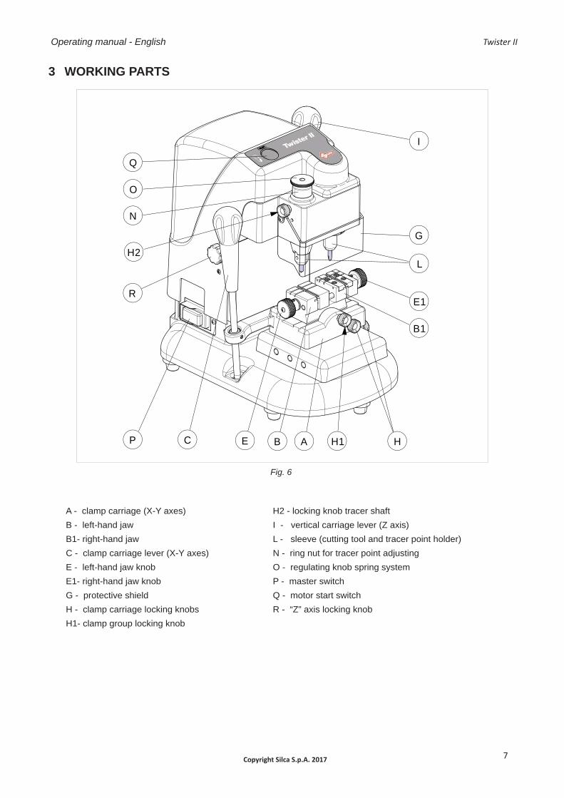
3 WORKING PARTS
Fig. 6
A - clamp carriage (X-Y axes)B - left-hand jawB1- right-hand jawC - clamp carriage lever (X-Y axes) E - left-hand jaw knobE1- right-hand jaw knobG - protective shieldH - clamp carriage locking knobsH1- clamp group locking knob
H2 - locking knob tracer shaftI - vertical carriage lever (Z axis)L - sleeve (cutting tool and tracer point holder) N - ring nut for tracer point adjustingO - regulating knob spring systemP - master switchQ - motor start switchR - “Z” axis locking knob
A H1B
B1
CP E
E1
L
I
R
Q
H
O
N
GH2

Operating manual - English Twister II
Copyright Silca S.p.A. 20178
3.1 TECHNICAL DATA
Electricity supply: 230V/50Hz110V/50-60Hz
Maximum absorbed power: 230V: 1,1 Amp. 180 Watt120V: 1,8 Amp. 160 Watt
Motor: One-speed single phase
Cutting tool: Super rapid steel HSS
Tool speed: 50Hz: 6000 rpm (+/- 10%) - 60Hz: 6000 rpm (+/- 10%)
Movements: on 3 axes: vertical axis on bars, longitudinal and transversal axes on ball guides
Clamp: universal interchangeable
Travel: X axis (lower): 40 mm - Y axis (upper): 50 mm - Z axis (vertical): 30 mm
Dimensions: width: 250 mm depth: 370 mm height: 370 mm
Weight: 24 Kg.
Sound pressure: 74,7 dB(A)
GRAPHICS ON THE TWISTER II MACHINE
THE USE OF PROTECTIVEGOGGLES IS REQUIRED
READ INSTRUCTIONS BEFORE USE
WARNING!TOOL IN ROTATION
WARNING! PRESENCE OF ELECTRIC POWER GROUND CONNECTION CUTTER ROTATION
DIRECTION

Operating manual - English Twister II
Copyright Silca S.p.A. 2017 9
3.2 ELECTRIC CIRCUIT
The main parts of the electrical and electronic circuit on the TWISTER II are listed below:
1) Machine plug2) Fuses 3,15 Amp rapid (230V) - 8 Amp delayed (120V)3) Master switch4) Led 5) Motor start switch6) Electric motor with collector 230/50 (120/50-60)
Fig. 7
Operating manual - English Twister II
Copyright Silca S.p.A. 201710
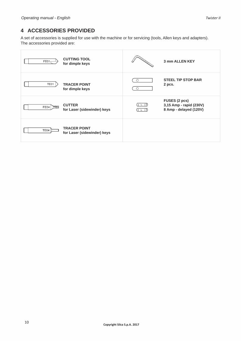
4 ACCESSORIES PROVIDED A set of accessories is supplied for use with the machine or for servicing (tools, Allen keys and adapters).The accessories provided are:
CUTTING TOOLfor dimple keys 3 mm ALLEN KEY
TRACER POINTfor dimple keys
STEEL TIP STOP BAR2 pcs.
CUTTERfor Laser (sidewinder) keys
FUSES (2 pcs)3,15 Amp - rapid (230V)8 Amp - delayed (120V)
TRACER POINTfor Laser (sidewinder) keys

Operating manual - English Twister II
Copyright Silca S.p.A. 2017 11
5 MACHINE INSTALLATION AND PREPARATION The key-cutting machine can be installed by the purchaser and does not require any special skills.The machine is supplied ready for use and does not need to be set up, except when changing to different tools. However, some checks and preparation for use need to be carried out by the operator.
5.1 CHECKING FOR DAMAGEThe TWISTER II key-cutting machine is solid and compact and will not normally damage if transport, unpacking and installation have all been carried out according to the instructions in this manual. However, it is always advisable to check that the machine has not suffered any damage .
5.2 ENVIRONMENTAL CONDITIONS To ensure that the best use is made of the TWISTER II key-cutting machine, certain parameters must be borne in mind:- damp, badly ventilated sites should be avoided.- the ideal conditions for the machine are:
between 10 and 40°C; relative humidity: approximately 60%
5.3 POSITIONING Place the key-cutting machine on a horizontal surface, solid enough to take the weight.For comfort when using the working parts of the machine, the workbench should be at the same height as the operator’s hips.It is important to leave clearance of at least 12” (30 cm) behind the machine and on each side to ensure proper ventilation.
ATTENTION: ensure that the machine voltage is the same as that of the power supply, which must be properly grounded and provided with a differential switch.
Fig. 8
5.4 DESCRIPTION OF WORK STATION The key-cutting machine needs only one operator, who has the following controls at his/her disposal:• master switch (P)• motor start switch (Q).• levers:
- lever (C) to move the clamp carriage - lever (I) to move the vertical carriage
Note: the letters in brackets refer to Fig. 6, page 7.
30 cm
30 cm
30 cm

Operating manual - English Twister II
Copyright Silca S.p.A. 201712
6 MACHINE REGULATION AND UTILIZATION Before carrying out cutting operations:• insert the proper cutter and tracer• activate the spring system (if cutting dimple keys) (ch.7.4)
6.1 FITTING AND REGULATING THE TOOLS
Fig. 9
ATTENTION: turn power off on machine. To fi t the tracer point and cutting tool into the sleeves:1) Place the tracer point all the way into the left-hand sleeve and secure by tightening the grub screw (M) (Fig. 10).2) Place the cutting tool all the way into the right-hand sleeve and secure by tightening the grub screw (M1).
Releasing the toolsUnscrew the grub screw (M) and (M1) to remove the tracer point and cutting tool from the sleeves.
M
M1
Fig. 10

Operating manual - English Twister II
Copyright Silca S.p.A. 2017 13
6.2 CALIBRATION OF CUTTER AND TRACER
Note: the TWISTER II key-cutting machine is equipped with a spring mechanism which allows precise duplication of dimple keys. The spring system is to be used only for dimple keys (chap.7.4) and is activated by rotating the ring nut (O).Once the appropriate cutter and tracer have been installed, place two identical key blanks into the clamps and proceed as follows:1) Loosen the upper ring nut (O).2) Loosen the bigger middle ring nut’s locking knob (H2).3) Turn the bigger middle ring nut (N) clockwise a few turns to lower the tracer.4) With the (I) lever lower the vertical carriage until the tracer point touches the top of the key in the left side clamp
(Fig. 12).5) Keeping the (I) lever downwards, turn the bigger middle ring nut (N) counter-clockwise until the cutter touches the
top of the key in the right side clamp (Fig. 13).6) Lock the bigger middle ring nut’s locking knob (H2).7) Turn the upper ring nut (O) clockwise up until it is tight to cut laser (sidewinder) type keys.
O
IN
H2
Fig. 11
Fig. 12
Fig. 13

Operating manual - English Twister II
Copyright Silca S.p.A. 201714
7 CUTTING OPERATIONS
ATTENTION: for complete safety during the cutting operations, take the following precautions:
• Always work with dry hands.• Ensure that the machine is properly grounded.• Wear protective goggles even if the machine is provided with a safety shield over the cutting tool.• Before starting the motor (switch Q), carry out the following operations:
a) place the pattern and blank keys into the clamps.b) install and calibrate the cutter and tracer (see chap.6.2).
• Keep hands away from the cutting tool in motion.
7.1 KEY CUTTING 1) Turn on the machine using switch (P).2) Once the keys have been loaded and gauged properly, press the switch (Q) to turn on the cutter.3) Using the lever (C) move the clamp group according to the cuts that have to be carried out.4) Using lever (I) lower the cutter/tracer group so that the tracer enters a dimple in the pattern key. Press the lever
(I) with suffi cient force to make sure the cutter removes all the necessary material from the key for the dimple being cut.
5) Repeat the operation for each dimple.6) After having carried out all the cuts, turn the machine off using the switch (Q) and remove the keys from the
clamps.
0
barretta di fermoAnschlagstabebarrette d’arretbarrita de tope
barra de encostoaanslagplaatje
tip stop bar
Fig. 14 Fig. 15
7.2 CUTTING KEYS WITH KEY STOPS1) Lock the sample key in the left hand clamp of the machine making sure that the key stop is pressedagainst the
clamp (Fig. 14).2) Lock the key to be cut in the right hand clamp of the machine making sure that the key stop ispressed against
the clamp.3) Every time cutter or tracer point are changed, check machine calibration according to chap.6.2.4) Cut the key according to chap.7.1 .

Operating manual - English Twister II
Copyright Silca S.p.A. 2017 15
7.3 CUTTING KEYS WITHOUT KEY STOPS1) Insert the tip stop bar into the appropriate slots on the clamp and load the key into the jaw so that the tip of the
key rests against the tip stop bar.2) Adjust the machine according to chap. 6.2. 3) Cut the key according to chap.7.1.
Cutting the edge If cuts are to be made on the edge, place the key in a vertical position.
Fig. 16
7.4 INSERTING THE SPRING SYSTEM FOR DIMPLE KEYSThe TWISTER II key-cutting machine is equipped with a spring mechanism which allows precise duplication of dimple keys. Using this system, it is possible to position the tracer into the groove of the sample fi rst and then proceed with cutting the key. The spring system is to be used only for dimple keys (Fig. 1) and is activated by rotating the ring nut (O).Note:for laser type keys (Fig. 1) deactivate this function.
7.5 CUTTING LASER (SIDEWINDER ) TYPE KEYSNOTE: before attempting to cut laser (sidewinder) type keys, deactivate the spring system for dimple keys using knob (O) (chap.7.4).1) Start the cutting operation by activating switch (Q).2) Lower the spindle and rest the tracer point on a cut part of the original key, cut the key and stop atthe beginning
of the cut.• secure the spindle at this height by means of knob (R).• carry out the cuts using only the left-hand lever (C).
Fig. 17

Operating manual - English Twister II
Copyright Silca S.p.A. 201716
7.6 CUTTING NARROW-BLADE LASER (SIDEWINDER) TYPE KEYS (ART.HU41P-HU55P-HU64P...)
The clamp can also be used to cut narrow-stemmed Laser (sidewinder) keys but requires the use of the adapter (optional). Proceed as follows:1) Open the clamps by loosening knobs (E) and (E1).2) Place the tip stop bar into the groove.3) Insert the adapter into the clamp.4) Insert the key so that it butts against the bar.5) Secure the adapter and key by tightening knob (E).6) Remove the bar and repeat the same operations on the right-hand jaw.Cutting:1) Before activating the start switch (Q) lower lever (I) close to the keys.2) Start the cutting operation by activating switch (Q).3) Lower the spindle, cut the key and stop at the beginning of the cut (cap.7.5).• secure the spindle at this height.• carry out the cuts using only lever (C).
Adattatori (opzionali)
Fig. 18
7.7 CUTTING KEYS FOR FICHETThe clamp can also be used to cut keys for FICHET (H profi le). Proceed as follows:1) open the clamps slightly by loosening knobs (E) and (E1) (Fig. 6, page 7).2) place the keys with the stop up against the clamp.3) secure the keys by tightening knobs (E) and (E1).Cutting:Turn on switch (Q), lower the collet assembly and position on the beginning of the cut.• secure the spindle at this height by means of knob (R).• carry out the cuts using only lever (C).
Fig. 19

Operating manual - English Twister II
Copyright Silca S.p.A. 2017 17
8 MAINTENANCE
ATTENTION: for repairs or replacement of parts for maintenance, the ‘CE’ mark is guaranteed only if original spare parts provided by the manufacturer are used.
Although the TWISTER II key-cutting machine does not require special maintenance, it is advisable to check and, if necessary, replace the parts subject to wear, such as: the belt (chap.8.1) and the lamp (chap.8.2). Replacement is simple and can be carried out by the operator.CLEANING: keep the carriage and clamps free of chippings from the cutting operations by cleaning with a dry brush.
ATTENTION: DO NOT USE COMPRESSED AIR!
ATTENTION: to keep the machine well maintained we recommend using protective oil, e.g. WD40 or similar, applied to the burnished mechanical parts. This prevents oxidation of the parts in question (clamps, guides, carriages, etc.).
Before starting any type of maintenance (checks or replacements), read the instructions below:• Never carry out maintenance or servicing with the machine switched on.• Always unplug the machine prior to servicing.• Follow all the instructions in the manual to the letter.• Use original spare parts.
8.1 REPLACING THE BELT AND ADJUSTING TENSIONIf the upper part of the machine vibrates, check the tension on the belt, as described below:1) Turn off the master switch and unplug the machine.2) Loosen the four screws (Y1), knob (R) (Fig. 6, page 7) and remove the upper casing (Y).3) Loosen (but do not remove) the four socket head screws (Y2) securing the motor.4) a) tension:
- increase belt tension by pushing the motor towards the back of the machine.b) replacement:- loosen the belt by pushing the motor slightly towards the tracer point and cutting tool.- remove the belt and replace.- tighten the tension by pushing the motor towards the back of the machine.
5) Secure the motor by tightening the four socket head screws (Y2). 6) Replace the upper casing (Y), secure with the four screws (Y1) and replace knob (R).
Fig. 20

Operating manual - English Twister II
Copyright Silca S.p.A. 201718
8.2 REPLACING THE LAMP To replace the lamp:1) Turn off the master switch and unplug the machine.2) Loosen the two screws (W1) and remove the lamp protection (W).3) Unscrew and replace the light bulb.4) Fit the lamp protection (W) and secure with the two screws (W1).
Fig. 21
8.3 CHECKING AND REPLACING THE FUSESThe fuses should always be checked with a continuity measuring instrument (tester, ohmeter, multimeter etc.) as a visible check may not reveal an electrical fault. Fuses must always be replaced with others of the same type and with the same Amps, as shown in the manual.The TWISTER II key-cutting machine has two fuses:3,15 Amps rapid for machines with 230 Volt8 Amps delayed for machines with 120 Voltplaced in the inlet socket, to protect the key-cutting machine from sudden changes in voltage or short circuits.It is advisable to check the fuses if the machine is not activated by turning on the master switch. Proceed as follows:1) Turn off the master switch (P) and remove the power cord.2) Remove the fuse board with the aid of a screwdriver.
Fig. 22

Operating manual - English Twister II
Copyright Silca S.p.A. 2017 19
8.4 REPLACING THE JAWS ON RIGHT-HAND CLAMP
Fig. 23
Make sure the motor ON switch is OFF
8.4.1 REPLACING LEFT JAW 1) Unscrew the knob (E1).2) Loosen the 2 screws (B2) and remove the jaw. 3) Fit the new jaw up against the left-hand side and align also
from the front.4) Tighten the 2 screws (B2) without exerting pressure. 5) Screw in the knob (E1).6) Fully tighten the screws (B2).
Fig. 24
8.4.2 REPLACING RIGHT JAW 1) Unscrew the knob (E1).2) Loosen the 2 screws (B3) and remove the jaw. 3) Fit the new jaw up against the right-hand side and align
also from the front.4) Tighten the 2 screws (B3) without exerting pressure. 5) Screw in the knob (E1).6) Fully tighten the screws (B3).
Fig. 25
B2
E1
B3
E1

Operating manual - English Twister II
Copyright Silca S.p.A. 201720
9 DISPOSAL For correct disposal please refer to current standards.
INFORMATION FOR USERS OF PROFESSIONAL EQUIPMENT
From “Actuation of Directive 2012/19/EU regarding Waste Electrical and Electronic Equipment (WEEE)”
The symbol of a crossed waste bin found on equipment or its packing indicates that at the end of the product’s useful life it must be collected separately from other waste so that it can be properly treated and recycled.In particular, separate collection of this professional equipment when no longer in use is organised and managed:
a) directly by the user when the equipment was placed on the market before 31 December 2010 and the user personally decides to eliminate it without replacing it with new equivalent equipment designed for the same use;
b) by the manufacturer, that is to say the subject which was the fi rst to introduce and market new equipment that replaces previous equipment, when the user decides to eliminate equipment placed on the market before 31 December 2010 at the end of its useful life and replace it with an equivalent product designed for the same use. In this latter case the user may ask the manufacturer to collect the existing equipment;
c) by the manufacturer, that is to say the subject which was the fi rst to introduce and market new equipment that replaces previous equipment, if it was placed on the market after 31 December 2010;
Suitable separate collection for the purpose of forwarding discarded equipment for recycling, treatment or disposal in an environmentally friendly way helps to avoid possible negative effects on the environment and human health and encourages re-use and/or recycling of the materials making up the equipment.
The sanctions currently provided for by law shall apply to users who dispose of products in unauthorised ways .

Operating manual - English Twister II
Copyright Silca S.p.A. 2017 21
10 AFTER-SALES SERVICE Silca provides full service to purchasers of the TWISTER II key-cutting machine.To ensure complete safety for the operator and machine, any job not specifi ed in this manual should be carried out by the manufacturer.
10.1 HOW TO REQUEST SERVICEThe limited warranty period for the TWISTER II key-cutting machine ensures free repairs or replacements of faulty parts within 24 months of purchase. All other service calls must be arranged by the customer with Silca or its Service Centres .

VITTORIO VENETO 09/06/2015 CE DECLARATION OF MACHINE COMPLIANCE SILCA S.p.A. - VIA PODGORA 20 ( Z.I.) 31029 VITTORIO VENETO (TV) - (ITALY) TEL. 0438 9136 - FAX. 0438 913800 Declares under its own responsibility that the Key-cutting machine model
TWISTER II complies with the requirements of the following European Directives: European Union DIRECTIVE 2006/42/CE (Machines) and with the ENISO 12100 – 1 & - 2 : 2003 + Amd. 1 : 2009 ENISO 14121 : 2007 Standards European Union DIRECTIVE 2004/108/CE (Electromagnetic Compatibility) and with the IEC 61000 – 6 – 3 :2006 , IEC 61000 – 6 – 1 :2005 CISPR14 – 1 : 2009 / EN 55014 – 1 :2009 IEC/EN 61000 – 3 – 2 : 2005 , IEC/EN 61000 - 3 – 3 .2005 Standards European Union DIRECTIVE 2006/95/CE (Low Voltage) | 15 | and with the IEC/EN 60204 – 1 : 2006 + Amd. 1 2009 Standards Claudio Tomasella of the Silca S.p.A. Research & Development Division is authorized to create a Technical File. General Manager Basic Production Center