Embed Size (px)
Citation preview
1323-DB-001-0-01
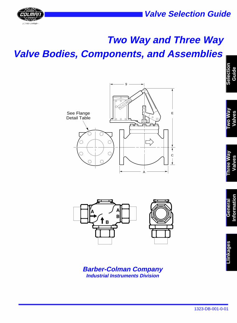
Valve Bodies, Components, and AssembliesTwo Way and Three Way
Th
ree
Way
Val
ves
Gen
eral
In
form
atio
nL
linka
ges
Valve Selection Guide
Barber-Colman Company
Industrial Instruments Division
Tw
o W
ayV
alve
s
E
C
A
9
See Flange Detail Table
Sel
ecti
on
G
uid
e
Commitment to Quality
International Standards
The International Standards Organization provides a series of international standards that are used to measure the Quality System of an organization and how it is managed. ISO 9001 is a specific standard that is applied to an organization that designs and manufactures products. The focus of this standard is how the Quality System assures the quality of the parts and services a company produces. ISO 9001 also looks at how a management system collects quality related data, and uti-lizes it to continually improve operations, reliability, productivity and other characteristics. Therefore, when an organization becomes certified under ISO 9001, it is the management system that has been certified.
Certification
On June 14, 1994, DNV (Det Norske Veritas Certification, Inc.) determined that the Quality System of the Industrial Instru-ments Division of Barber-Colman Company is certified to ISO 9001. This certification represents a standard of consistency and view of quality that is accepted worldwide. It allows a common point of reference in terminology and functional concepts that enhances our customer communications. When choosing among potential suppliers, customers can count on the char-acteristics of Barber-Colman as an ISO 9001 certified supplier.
Commitment
The Quality Manual and Procedures that form the basis of our Quality System originate from our stated quality policy:The Quality Objective of the Industrial Instruments Division of Barber-Colman Company is to provide quality products and services that meet or exceed customer requirements. To achieve our Quality Objective, the Industrial Instruments Division is committed to:
• Implementing and maintaining a continuous improvement process.
• Implementing and maintaining the Quality System described in the Quality Manual and the Procedure Manual.
• Ensuring the Quality Policy is communicated and understood at all levels of the organization.
• Providing adequate resources and assigning trained personnel for management, performance of work, verification activities and audits.
ISO 9001 Key Elements
1) Management responsibility to establish a quality representative and organization that provides feedback to management on quality issues.
2) Establish a documented quality system including a Quality Manual and Procedures. 3) Verify the needs and expectations of the customer. 4) Control and verify the design of new products to ensure specified requirements are met. 5) Control of all documents related to the control of quality. 6) Ensure that purchasing material and suppliers conform to specified requirements.
7)Identify and trace products through all stages of manufacturing. 8) Provide documented plans for control of all manufacturing processes. 9) Inspection and testing to verify requirements are met.
10) Equipment used for inspection, measurement and test is calibrated and maintained. 11) Inspection and test status of manufactured product is clearly identified. 12) Non-conforming product is prevented from unintended use. 13) Implementation of a system for corrective and preventive action. 14) Handling, storage, packaging and delivery procedures that prevent damage. 15) Establish and retain records that support the Quality System. 16) Verification of Quality System compliance through internal quality audits. 17) Identification and documentation of employee qualification, education and training needs. 18) Establish and utilize statistical techniques for process monitoring.
ISO 9001
1323-DB-001-0-01
Barber-Colman Company, Loves Park, IL
Page 3
Two-Way Valve Selection . . . . . . . . . . . . . . . . . . . . . . . . . . . . . . . . . . . . . . . . . . . . . . . . . . . 6
Three-Way Valve Selection . . . . . . . . . . . . . . . . . . . . . . . . . . . . . . . . . . . . . . . . . . . . . . . . . 8
Union End, Flared; Hydraulic . . . . . . . . . . . . . . . . . . . . . . . . . . . . . . . . . . . . . . . . . . . . . . . . 9Screwed, Union Sweat; Hydraulic . . . . . . . . . . . . . . . . . . . . . . . . . . . . . . . . . . . . . . . . . . . 12Screwed, Union Sweat; Electric . . . . . . . . . . . . . . . . . . . . . . . . . . . . . . . . . . . . . . . . . . . . . 15High Temp; Electric . . . . . . . . . . . . . . . . . . . . . . . . . . . . . . . . . . . . . . . . . . . . . . . . . . . . . . 22Mixing, Sequencing; Flared . . . . . . . . . . . . . . . . . . . . . . . . . . . . . . . . . . . . . . . . . . . . . . . . 25Mixing, Diverting; Hydraulic . . . . . . . . . . . . . . . . . . . . . . . . . . . . . . . . . . . . . . . . . . . . . . . . 28Mixing, Diverting; Electric . . . . . . . . . . . . . . . . . . . . . . . . . . . . . . . . . . . . . . . . . . . . . . . . . . 31Static Pressure Versus Temperature Ratings . . . . . . . . . . . . . . . . . . . . . . . . . . . . . . . . . . 42Flow Curves and Rangeability . . . . . . . . . . . . . . . . . . . . . . . . . . . . . . . . . . . . . . . . . . . . . . 43Guidelines . . . . . . . . . . . . . . . . . . . . . . . . . . . . . . . . . . . . . . . . . . . . . . . . . . . . . . . . . . . . . . 44Valve Sizing Information for Water . . . . . . . . . . . . . . . . . . . . . . . . . . . . . . . . . . . . . . . . . . . 46Valve Sizing Information for Steam . . . . . . . . . . . . . . . . . . . . . . . . . . . . . . . . . . . . . . . . . . 49Valve/Actuator Wiring Diagrams . . . . . . . . . . . . . . . . . . . . . . . . . . . . . . . . . . . . . . . . . . . . . 52Valve Body Cross Reference . . . . . . . . . . . . . . . . . . . . . . . . . . . . . . . . . . . . . . . . . . . . . . . 59Valve Linkage Selection Guide . . . . . . . . . . . . . . . . . . . . . . . . . . . . . . . . . . . . . . . . . . . . . . 60Valve Linkages . . . . . . . . . . . . . . . . . . . . . . . . . . . . . . . . . . . . . . . . . . . . . . . . . . . . . . . . . . 66
Table of Contents
Selection Guide
1323-DB-001-0-01
Barber-Colman Company, Loves Park, IL
Page 4
S
elec
tio
nG
uid
e
How to Use this Guide
This guide will direct you to
• part numbers of valve assemblies for specific types of applications• part numbers of components of those assemblies – valve body, actuator, linkage.
The model numbering scheme on the next page explains how the part number is composed.
To find the part number of the assembly or component you need:
1) Refer to the table on page 6 or 7 for two way valves, and page 8 for three way valves.2) Find the appropriate application parameters in the first row of the table.3) Select the desired valve body type that is designed for that application.4) To determine the actuator and linkage part numbers, follow the column down to the lower table.5) Find the appropriate actuator input signal in the left column of the lower table.6) Go to the first page number indicated to begin the assembly selection procedure. There you will find the
following tables:
Table 1. Valve body specificationsTable 2. Valve actuator specificationsTable 3. Factory assemblies (two way) or dimensions (three way)Table 4. Dimensions (two way) or flow patterns (three way)Table 5. Restrictions
electio Guide
Selection Guide
1323-DB-001-0-01
Barber-Colman Companyl, Loves Park, IL
Page 5
Sel
ecti
on
Gu
ide4 5
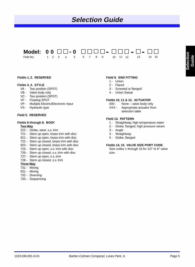
00 - 0 - - -Model:Field No. 1 2 3 6 7 8 9 10 11 12 13 14 15
Fields 1, 2. RESERVED
Fields 3, 4. STYLE
VA - Two position (SPST)VB - Valve body onlyVC - Two position (SPDT)VF - Floating SPDTVP - Multiple Electric/Electronic InputVS - Hydraulic type
Field 5. RESERVED
Fields 6 through 8. BODYTwo Way
222 - Globe, steel, s.s. trim721 - Stem up open, brass trim with disc921 - Stem up open, brass trim with disc722 - Stem up closed, brass trim with disc922 - Stem up closed, brass trim with disc725 - Stem up open, s.s. trim with disc726 - Stem up closed, s.s. trim with disc727 - Stem up open, s.s. trim728 - Stem up closed, s.s. trim
Three Way
731 - Mixing931 - Mixing732 - Diverting733 - Sequencing
Field 9. END FITTING
1 - Union2 - Flared3 - Screwed or flanged4 - Union Sweat
Fields 10, 11 & 12. ACTUATOR
000 - None – valve body onlyXXX - Appropriate actuator from
selection table
Field 13. PATTERN
1 - Straightway, high temperature water2 - Globe, flanged, high pressure steam3 - Angle4 - Straightway5 - Globe, flanged
Fields 14, 15. VALVE SIZE PORT CODE
Size codes 1 through 16 for 1/2" to 6" valve size.
Two-Way
1323-DB-001-0-01
Barber-Colman Company, Loves Park, IL
Page 6
S
elec
tio
n
Gu
ide
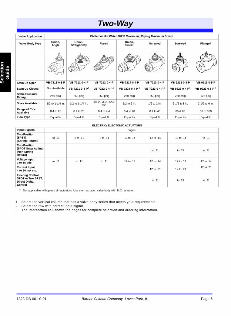
HOW TO USE TABLE:
1. Select the vertical column that has a valve body series that meets your requirements.2. Select the row with correct input signal.3. The intersection cell shows the pages for complete selection and ordering information.
a
Not applicable with gear train actuators. Use stem up open valve body with N.C. actuator.
Valve Application Chilled or Hot Water 281
°
F Maximum; 35 psig Maximum Steam
Valve Body Type Union, Angle
Union,Straightway Flared Union,
Sweat Screwed Screwed Flanged
Stem Up Open VB-7211-0-3-P VB-7211-0-4-P VB-7212-0-4-P VB-7214-0-4-P VB-7213-0-4-P VB-9213-0-4-P VB-9213-0-5-P
Stem Up Closed Not Available VB-7221-0-4-P
a
VB-7222-0-4-P
a
VB-7224-0-4-P
a
VB-7223-0-4-P
a
VB-9223-0-4-P
a
VB-9223-0-5-P
a
Static Pressure Rating
250 psig 250 psig 250 psig 250 psig 250 psig 250 psig 125 psig
Sizes Available
1/2 to 1-1/4 in. 1/2 to 1-1/4 in.5/8 in. O.D., SAE
45
°
1/2 to 2 in. 1/2 to 2 in. 2-1/2 & 3 in. 2-1/2 to 6 in.
Range of Cv’s Available
0.4 to 20 0.4 to 20 0.4 to 4.4 0.4 to 40 0.4 to 40 65 & 85 56 to 350
Flow Type
Equal % Equal % Equal % Equal % Equal % Equal % Equal %
ELECTRIC/ ELECTONIC ACTUATORS
Input Signals
Pages
Two-Position (SPST) (Spring Return)
to 11 8 to 11 8 to 11 12 to 14 12 to 14 12 to 14 to 21
Two-Position(SPDT Snap Acting)(Non-Spring Return)
to 21 to 21 to 21
Voltage Input 2 to 15 Vdc
to 11 to 11 to 11 12 to 14 12 to 14 12 to 14 12 to 14
Current Input 4 to 20 mA etc.
12 to 21 12 to 21 12 to 21
Floating Control,SPDT or Two SPST, Direct Digital Control
to 21 to 21 to 21
Two-Way
Two-Way
1323-DB-001-0-01
Barber-Colman Company, Loves Park, IL
Page 7
Sel
ecti
on
G
uid
e
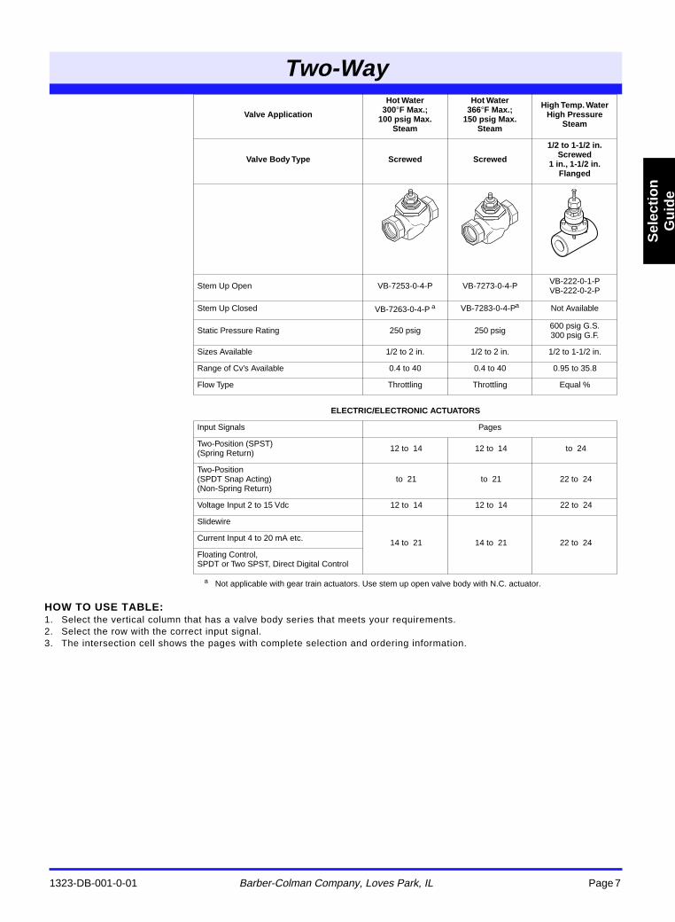
HOW TO USE TABLE:
1. Select the vertical column that has a valve body series that meets your requirements.2. Select the row with the correct input signal.3. The intersection cell shows the pages with complete selection and ordering information.
a
Not applicable with gear train actuators. Use stem up open valve body with N.C. actuator.
Valve Application
Hot Water 300
°
F Max.; 100 psig Max.
Steam
Hot Water 366
°
F Max.; 150 psig Max.
Steam
High Temp. WaterHigh Pressure
Steam
Valve Body Type Screwed Screwed
1/2 to 1-1/2 in. Screwed
1 in., 1-1/2 in. Flanged
Stem Up Open VB-7253-0-4-P VB-7273-0-4-P VB-222-0-1-PVB-222-0-2-P
Stem Up Closed VB-7263-0-4-P
a
VB-7283-0-4-P
a
Not Available
Static Pressure Rating 250 psig 250 psig 600 psig G.S.300 psig G.F.
Sizes Available 1/2 to 2 in. 1/2 to 2 in. 1/2 to 1-1/2 in.
Range of Cv’s Available 0.4 to 40 0.4 to 40 0.95 to 35.8
Flow Type Throttling Throttling Equal %
ELECTRIC/ELECTRONIC ACTUATORS
Input Signals Pages
Two-Position (SPST) (Spring Return) 12 to 14 12 to 14 to 24
Two-Position(SPDT Snap Acting)(Non-Spring Return)
to 21 to 21 22 to 24
Voltage Input 2 to 15 Vdc 12 to 14 12 to 14 22 to 24
Slidewire
14 to 21 14 to 21 22 to 24Current Input 4 to 20 mA etc.
Floating Control,SPDT or Two SPST, Direct Digital Control
Three-Way
1323-DB-001-0-01
Barber-Colman Company, Loves Park, IL
Page 8
S
elec
tio
n
Gu
ide
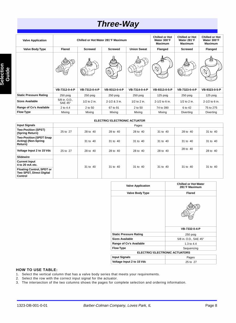
HOW TO USE TABLE:
1. Select the vertical column that has a valve body series that meets your requirements.2. Select the row with the correct input signal for the actuator.3. The intersection of the two columns shows the pages for complete selection and ordering information.
Valve Application Chilled or Hot Water 281
°
F MaximumChilled or Hot Water 300
°
F Maximum
Chilled or Hot Water 281
°
F Maximum
Chilled or Hot Water 300
°
F Maximum
Valve Body Type Flared Screwed Screwed Union Sweat Flanged Screwed Flanged
VB-7312-0-4-P VB-7313-0-4-P VB-9313-0-4-P VB-7314-0-4-P VB-9313-0-5-P VB-7323-0-4-P VB-9323-0-5-P
Static Pressure Rating
250 psig 250 psig 250 psig 250 psig 125 psig 250 psig 125 psig
Sizes Available
5/8 in. O.D., SAE 45
°
1/2 to 2 in. 2-1/2 & 3 in. 1/2 to 2 in. 2-1/2 to 6 in. 1/2 to 2 in. 2-1/2 to 6 in.
Range of Cv’s Available
2 to 4.4 2 to 50 67 to 91 2 to 50 74 to 390 6 to 42 75 to 275
Flow Type
Mixing Mixing Mixing Mixing Mixing Diverting Diverting
ELECTRIC/ ELECTRONIC ACTUATOR
Input Signals
Pages
Two-Position (SPST) (Spring Return)
25 to 27 28 to 40 28 to 40 28 to 40 31 to 40 28 to 40 31 to 40
Two-Position (SPDT Snap Acting) (Non-Spring Return)
31 to 40 31 to 40 31 to 40 31 to 40 31 to 40 31 to 40
Voltage Input 2 to 15 Vdc
25 to 27 28 to 40 28 to 40 28 to 40 28 to 40 28 to 40
28 to 40
Slidewire
31 to 40 31 to 40 31 to 40 31 to 40 31 to 40 31 to 40
Current Input4 to 20 mA etc.
Floating Control, SPDT or Two SPST, Direct Digital Control
Valve ApplicationChilled or Hot Water
281
°
F Maximum
Valve Body Type Flared
VB-7332-0-4-P
Static Pressure Rating
250 psig
Sizes Available
5/8 in. O.D., SAE 45
°
Range of Cv’s Available
1.3 to 4.4
Flow Type
Sequencing
ELECTRIC/ ELECTRONIC ACTUATORS
Input Signals
Pages
Voltage Input 2 to 15 Vdc
25 to 27
Three-Way
Tw
o W
ayV
alve
s
Union End, Flared; Hydraulic
1323-DB-001-0-01
Barber-Colman Company, Loves Park, IL
Page 9
a
CAUTION: Fittings and/or piping schedules must meet or exceed working static pressure requirements.
b
CAUTION: Freeze protection required for fluid temperatures below 32
°
F (0
°
C). Do not use Hydraulic Actuators with fluid temperatures below 40
°
F(4
°
C).
c
Factory assemblies are not available for two-position applications using reduced port valve bodies.
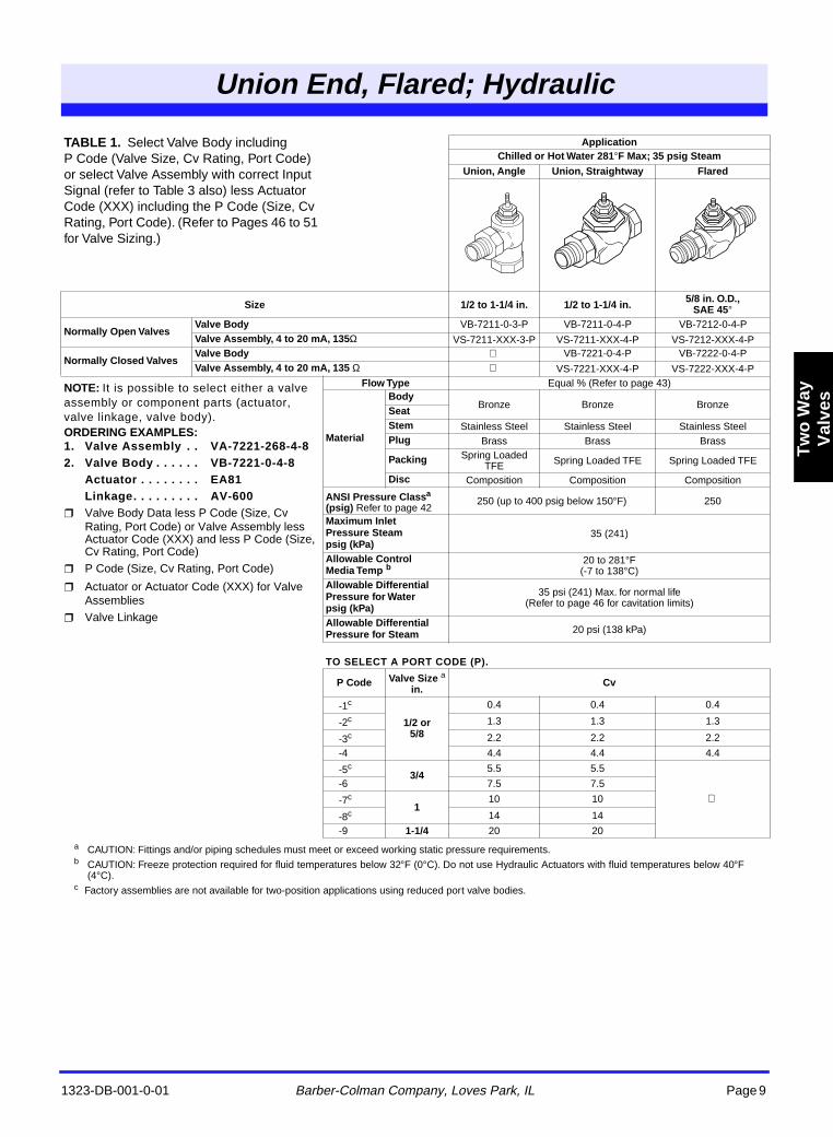
TABLE 1.
Select Valve Body including P Code (Valve Size, Cv Rating, Port Code) or select Valve Assembly with correct Input Signal (refer to Table 3 also) less Actuator Code (XXX) including the P Code (Size, Cv Rating, Port Code). (Refer to Pages 46 to 51 for Valve Sizing.)
ApplicationChilled or Hot Water 281
°
F Max; 35 psig Steam
Union, Angle Union, Straightway Flared
Size 1/2 to 1-1/4 in. 1/2 to 1-1/4 in.5/8 in. O.D.,
SAE 45
°
Normally Open ValvesValve Body
VB-7211-0-3-P VB-7211-0-4-P VB-7212-0-4-P
Valve Assembly, 4 to 20 mA, 135
Ω
VS-7211-XXX-3-P VS-7211-XXX-4-P VS-7212-XXX-4-P
Normally Closed ValvesValve Body
VB-7221-0-4-P VB-7222-0-4-P
Valve Assembly, 4 to 20 mA, 135
Ω
VS-7221-XXX-4-P VS-7222-XXX-4-P
NOTE:
It is possible to select either a valve assembly or component parts (actuator, valve linkage, valve body).
ORDERING EXAMPLES:1. Valve Assembly . . VA-7221-268-4-82. Valve Body . . . . . . VB-7221-0-4-8
Actuator . . . . . . . . EA81Linkage. . . . . . . . . AV-600
Valve Body Data less P Code (Size, Cv Rating, Port Code) or Valve Assembly less Actuator Code (XXX) and less P Code (Size, Cv Rating, Port Code)
P Code (Size, Cv Rating, Port Code)
Actuator or Actuator Code (XXX) for Valve Assemblies
Valve Linkage
Flow Type
Equal % (Refer to page 43)
Material
Body
Bronze Bronze Bronze
SeatStem
Stainless Steel Stainless Steel Stainless Steel
Plug
Brass Brass Brass
Packing
Spring Loaded TFE Spring Loaded TFE Spring Loaded TFE
Disc
Composition Composition Composition
ANSI Pressure Class
a
(psig)
Refer to page 42250 (up to 400 psig below 150
°
F) 250
Maximum Inlet Pressure Steam psig (kPa)
35 (241)
Allowable Control Media Temp
b
20 to 281
°
F(-7 to 138
°
C)
Allowable Differential Pressure for Waterpsig (kPa)
35 psi (241) Max. for normal life(Refer to page 46 for cavitation limits)
Allowable Differential Pressure for Steam
20 psi (138 kPa)
TO SELECT A PORT CODE (P).
P Code Valve Size
a
in.Cv
-1
c
1/2 or 5/8
0.4 0.4 0.4
-2
c
1.3 1.3 1.3
-3
c
2.2 2.2 2.2
-4 4.4 4.4 4.4
-5
c
3/4
5.5 5.5
-6 7.5 7.5
-7
c
1
10 10
-8
c
14 14
-9
1-1/4
20 20
UnionEnd, FlareHydraic
Two Way
Valves
Union End, Flared; Hydraulic
1323-DB-001-0-01 Barber-Colman Company, Loves Park, IL Page 10
Tw
o W
ay
Val
ves
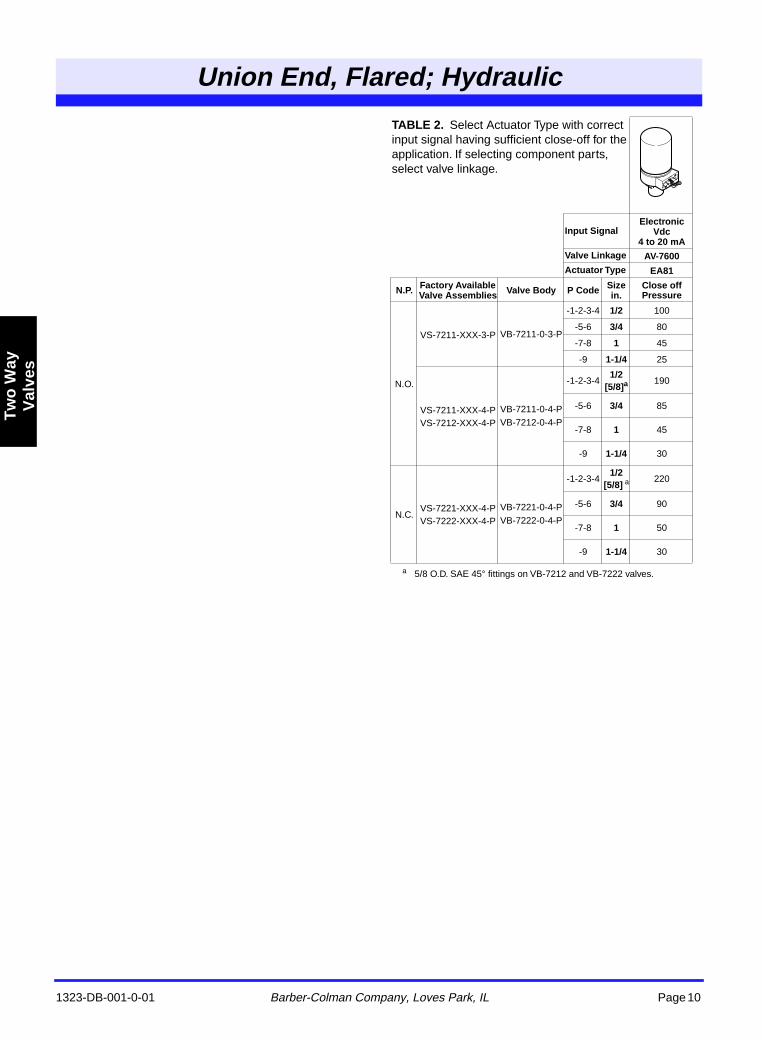
a 5/8 O.D. SAE 45° fittings on VB-7212 and VB-7222 valves.
TABLE 2. Select Actuator Type with correct input signal having sufficient close-off for the application. If selecting component parts, select valve linkage.
Input SignalElectronic
Vdc 4 to 20 mA
Valve Linkage AV-7600Actuator Type EA81
N.P. Factory Available Valve Assemblies Valve Body P Code Size
in.Close off Pressure
N.O.
VS-7211-XXX-3-P VB-7211-0-3-P
-1-2-3-4 1/2 100
-5-6 3/4 80
-7-8 1 45
-9 1-1/4 25
VS-7211-XXX-4-PVS-7212-XXX-4-P
VB-7211-0-4-PVB-7212-0-4-P
-1-2-3-41/2
[5/8]a190
-5-6 3/4 85
-7-8 1 45
-9 1-1/4 30
N.C.VS-7221-XXX-4-PVS-7222-XXX-4-P
VB-7221-0-4-PVB-7222-0-4-P
-1-2-3-41/2
[5/8] a220
-5-6 3/4 90
-7-8 1 50
-9 1-1/4 30
Tw
o W
ayV
alve
s
Union End, Flared; Hydraulic
1323-DB-001-0-01 Barber-Colman Company, Loves Park, IL Page 11
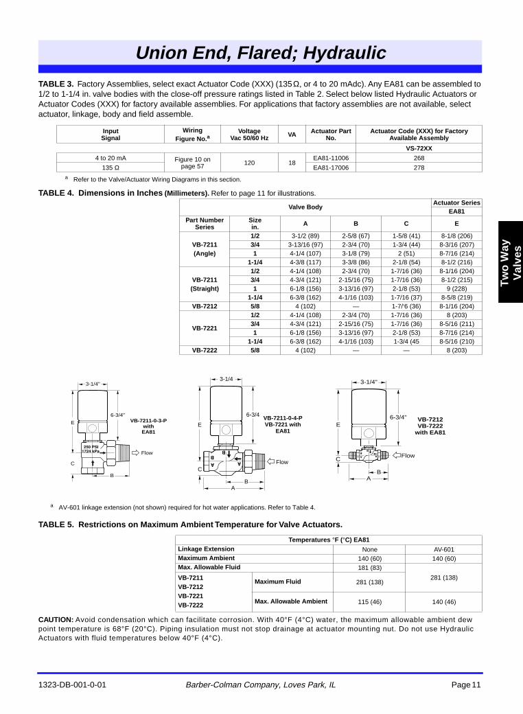
TABLE 3. Factory Assemblies, select exact Actuator Code (XXX) (135 Ω, or 4 to 20 mAdc). Any EA81 can be assembled to 1/2 to 1-1/4 in. valve bodies with the close-off pressure ratings listed in Table 2. Select below listed Hydraulic Actuators or Actuator Codes (XXX) for factory available assemblies. For applications that factory assemblies are not available, select actuator, linkage, body and field assemble.
TABLE 4. Dimensions in Inches (Millimeters). Refer to page 11 for illustrations.
TABLE 5. Restrictions on Maximum Ambient Temperature for Valve Actuators.
CAUTION: Avoid condensation which can facilitate corrosion. With 40°F (4°C) water, the maximum allowable ambient dew point temperature is 68°F (20°C). Piping insulation must not stop drainage at actuator mounting nut. Do not use Hydraulic Actuators with fluid temperatures below 40°F (4°C).
a Refer to the Valve/Actuator Wiring Diagrams in this section.
InputSignal
WiringFigure No.a
VoltageVac 50/60 Hz VA Actuator Part
No.Actuator Code (XXX) for Factory
Available Assembly
VS-72XX
4 to 20 mA Figure 10 on page 57 120 18
EA81-11006 268
135 Ω EA81-17006 278
Valve BodyActuator Series
EA81Part Number
SeriesSizein. A B C E
VB-7211(Angle)
1/2 3-1/2 (89) 2-5/8 (67) 1-5/8 (41) 8-1/8 (206)3/4 3-13/16 (97) 2-3/4 (70) 1-3/4 (44) 8-3/16 (207)1 4-1/4 (107) 3-1/8 (79) 2 (51) 8-7/16 (214)
1-1/4 4-3/8 (117) 3-3/8 (86) 2-1/8 (54) 8-1/2 (216)
VB-7211(Straight)
1/2 4-1/4 (108) 2-3/4 (70) 1-7/16 (36) 8-1/16 (204)3/4 4-3/4 (121) 2-15/16 (75) 1-7/16 (36) 8-1/2 (215)1 6-1/8 (156) 3-13/16 (97) 2-1/8 (53) 9 (228)
1-1/4 6-3/8 (162) 4-1/16 (103) 1-7/16 (37) 8-5/8 (219)VB-7212 5/8 4 (102) — 1-7/‘6 (36) 8-1/16 (204)
VB-7221
1/2 4-1/4 (108) 2-3/4 (70) 1-7/16 (36) 8 (203)3/4 4-3/4 (121) 2-15/16 (75) 1-7/16 (36) 8-5/16 (211)1 6-1/8 (156) 3-13/16 (97) 2-1/8 (53) 8-7/16 (214)
1-1/4 6-3/8 (162) 4-1/16 (103) 1-3/4 (45 8-5/16 (210)VB-7222 5/8 4 (102) — — 8 (203)
Temperatures °F (°C) EA81Linkage Extension None AV-601Maximum Ambient 140 (60) 140 (60)Max. Allowable Fluid 181 (83)
281 (138)VB-7211VB-7212VB-7221VB-7222
Maximum Fluid 281 (138)
Max. Allowable Ambient 115 (46) 140 (46)
3-1/4"
6-3/4"
E
C
B
Flow
VB-7211-0-3-P
with EA81
Flow
3-1/4
6-3/4
BA
E
C
VB-7211-0-4-P VB-7221 with
EA81
Flow
3-1/4"
6-3/4"E
C
AB
VB-7212 VB-7222
with EA81
a AV-601 linkage extension (not shown) required for hot water applications. Refer to Table 4.
Screwed, Union Sweat; Hydraulic
1323-DB-001-0-01
Barber-Colman Company, Loves Park, IL
Page 12
T
wo
Way
Val
ves
a
CAUTION: Freeze protection required for fluid temperatures below 32
°
F (0
°
C). Do not use Hydraulic Actuators with fluid temperatures below 40
°
F (4
°
C).
b
Factory assemblies are not available for two-position applications using reduced port valve bodies.
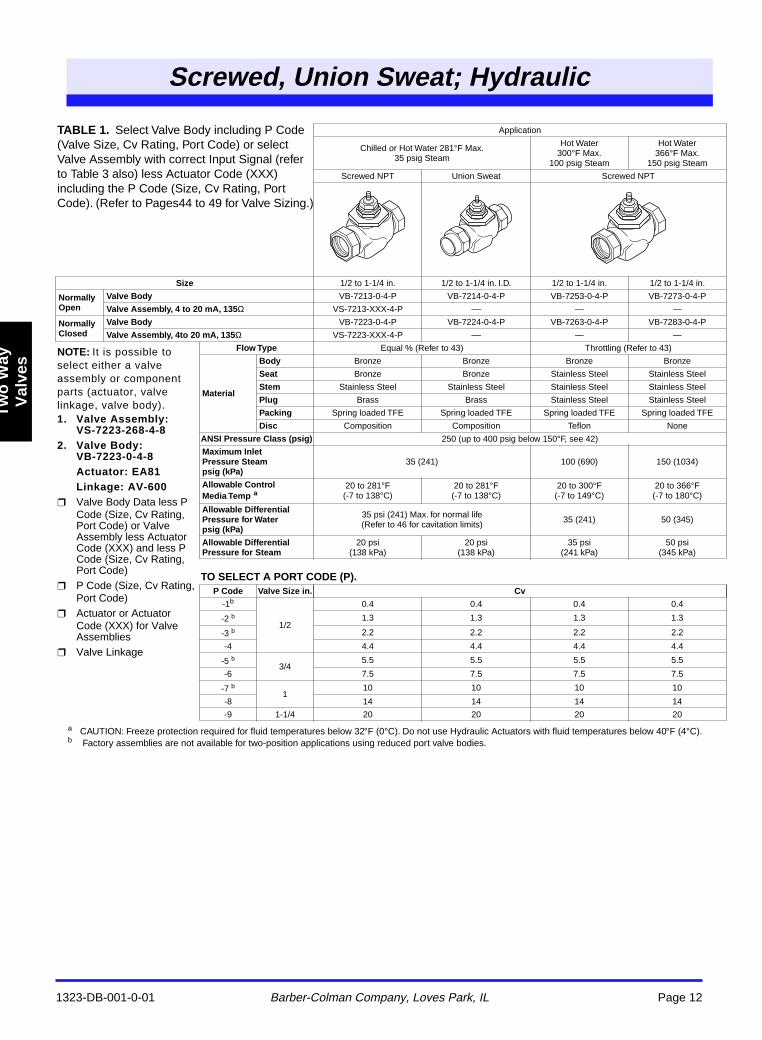
TABLE 1.
Select Valve Body including P Code (Valve Size, Cv Rating, Port Code) or select Valve Assembly with correct Input Signal (refer to Table 3 also) less Actuator Code (XXX) including the P Code (Size, Cv Rating, Port Code). (Refer to Pages44 to 49 for Valve Sizing.)
Application
Chilled or Hot Water 281
°
F Max.35 psig Steam
Hot Water 300
°
F Max.100 psig Steam
Hot Water366
°
F Max.150 psig Steam
Screwed NPT Union Sweat Screwed NPT
Size
1/2 to 1-1/4 in. 1/2 to 1-1/4 in. I.D. 1/2 to 1-1/4 in. 1/2 to 1-1/4 in.
Normally Open
Valve Body
VB-7213-0-4-P VB-7214-0-4-P VB-7253-0-4-P VB-7273-0-4-P
Valve Assembly, 4 to 20 mA, 135
Ω
VS-7213-XXX-4-P –– — —
Normally Closed
Valve Body
VB-7223-0-4-P VB-7224-0-4-P VB-7263-0-4-P VB-7283-0-4-P
Valve Assembly, 4to 20 mA, 135
Ω
VS-7223-XXX-4-P –– — —
NOTE:
It is possible to select either a valve assembly or component parts (actuator, valve linkage, valve body).
1. Valve Assembly: VS-7223-268-4-8
2. Valve Body: VB-7223-0-4-8Actuator: EA81Linkage: AV-600
Valve Body Data less P Code (Size, Cv Rating, Port Code) or Valve Assembly less Actuator Code (XXX) and less P Code (Size, Cv Rating, Port Code)
P Code (Size, Cv Rating, Port Code)
Actuator or Actuator Code (XXX) for Valve Assemblies
Valve Linkage
Flow Type
Equal % (Refer to 43) Throttling (Refer to 43)
Material
Body
Bronze Bronze Bronze Bronze
Seat
Bronze Bronze Stainless Steel Stainless Steel
Stem
Stainless Steel Stainless Steel Stainless Steel Stainless Steel
Plug
Brass Brass Stainless Steel Stainless Steel
Packing
Spring loaded TFE Spring loaded TFE Spring loaded TFE Spring loaded TFE
Disc
Composition Composition Teflon None
ANSI Pressure Class (psig)
250 (up to 400 psig below 150
°
F, see 42)
Maximum Inlet Pressure Steam psig (kPa)
35 (241) 100 (690) 150 (1034)
Allowable Control Media Temp
a
20 to 281
°
F(-7 to 138
°
C)20 to 281
°
F(-7 to 138
°
C)20 to 300
°
F(-7 to 149
°
C)20 to 366
°
F(-7 to 180
°
C)
Allowable Differential Pressure for Waterpsig (kPa)
35 psi (241) Max. for normal life(Refer to 46 for cavitation limits) 35 (241) 50 (345)
Allowable Differential Pressure for Steam
20 psi(138 kPa)
20 psi(138 kPa)
35 psi(241 kPa)
50 psi(345 kPa)
TO SELECT A PORT CODE (P).
P Code Valve Size in. Cv
-1
b
1/2
0.4 0.4 0.4 0.4
-2
b
1.3 1.3 1.3 1.3
-3
b
2.2 2.2 2.2 2.2
-4 4.4 4.4 4.4 4.4
-5
b
3/45.5 5.5 5.5 5.5
-6 7.5 7.5 7.5 7.5
-7
b
110 10 10 10
-8 14 14 14 14
-9 1-1/4 20 20 20 20
crewedUnion weat; ydrauli
Two Way
Valves
1323-DB-001-0-01 Barber-Colman Company, Loves Park, IL Page 13
Screwed, Union Sweat; Hydraulic
Two
Way
V
alve
s
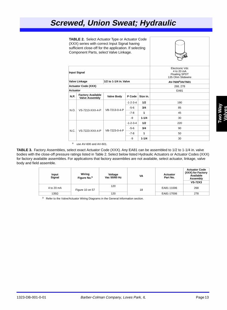
TABLE 3. Factory Assemblies, select exact Actuator Code (XXX). Any EA81 can be assembled to 1/2 to 1-1/4 in. valve bodies with the close-off pressure ratings listed in Table 2. Select below listed Hydraulic Actuators or Actuator Codes (XXX) for factory available assemblies. For applications that factory assemblies are not available, select actuator, linkage, valve body and field assemble.
a use AV-600 and AV-601.
a Refer to the Valve/Actuator Wiring Diagrams in the General Information section.
TABLE 2. Select Actuator Type or Actuator Code (XXX) series with correct Input Signal having sufficient close-off for the application. If selecting Component Parts, select Valve Linkage.
Input Signal
Electronic Vdc4 to 20 mA
Floating SPDT135 Ohm Slidewire
Valve Linkage 1/2 to 1-1/4 in. Valve AV-7600a/AV7601Actuator Code (XXX) 268, 278
Actuator EA81
N.P. Factory Available Valve Assembly Valve Body P Code Size in.
N.O. VS-7213-XXX-4-P VB-7213-0-4-P
-1-2-3-4 1/2 190
-5-6 3/4 85
-7-8 1 45
-9 1-1/4 30
N.C. VS-7223-XXX-4-P VB-7223-0-4-P
-1-2-3-4 1/2 220
-5-6 3/4 90
-7-8 1 50
-9 1-1/4 30
InputSignal
WiringFigure No.a
Voltage Vac 50/60 Hz VA Actuator
Part No.
Actuator Code (XXX) for Factory
Available AssemblyVS-72X3
4 to 20 mAFigure 10 on 57
12018
EA81-11006 268
135Ω 120 EA81-17006 278
Screwed, Union Sweat; Hydraulic
1323-DB-001-0-01 Barber-Colman Company, Loves Park, IL Page 14
Tw
o W
ayV
alve
s
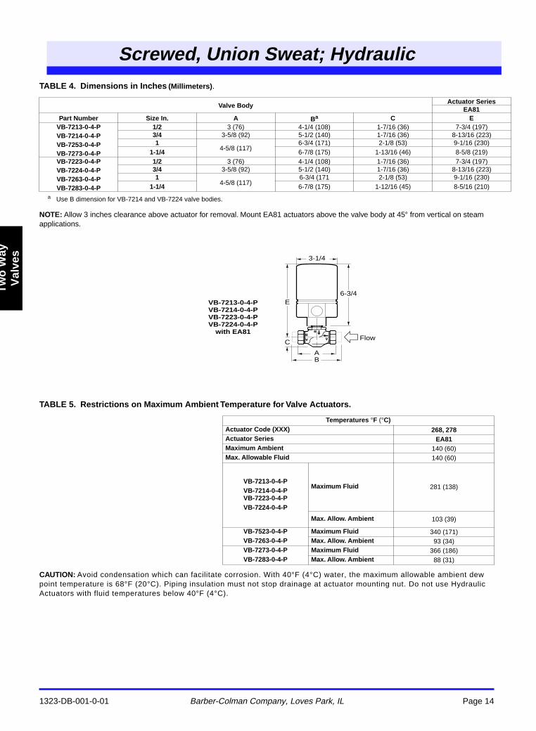
TABLE 4. Dimensions in Inches (Millimeters).
NOTE: Allow 3 inches clearance above actuator for removal. Mount EA81 actuators above the valve body at 45° from vertical on steam applications.
TABLE 5. Restrictions on Maximum Ambient Temperature for Valve Actuators.
CAUTION: Avoid condensation which can facilitate corrosion. With 40°F (4°C) water, the maximum allowable ambient dew point temperature is 68°F (20°C). Piping insulation must not stop drainage at actuator mounting nut. Do not use Hydraulic Actuators with fluid temperatures below 40°F (4°C).
a Use B dimension for VB-7214 and VB-7224 valve bodies.
Valve BodyActuator Series
EA81Part Number Size In. A Ba C E
VB-7213-0-4-PVB-7214-0-4-PVB-7253-0-4-PVB-7273-0-4-P
1/2 3 (76) 4-1/4 (108) 1-7/16 (36) 7-3/4 (197)3/4 3-5/8 (92) 5-1/2 (140) 1-7/16 (36) 8-13/16 (223)1
4-5/8 (117)6-3/4 (171) 2-1/8 (53) 9-1/16 (230)
1-1/4 6-7/8 (175) 1-13/16 (46) 8-5/8 (219)VB-7223-0-4-PVB-7224-0-4-PVB-7263-0-4-PVB-7283-0-4-P
1/2 3 (76) 4-1/4 (108) 1-7/16 (36) 7-3/4 (197)3/4 3-5/8 (92) 5-1/2 (140) 1-7/16 (36) 8-13/16 (223)1
4-5/8 (117)6-3/4 (171 2-1/8 (53) 9-1/16 (230)
1-1/4 6-7/8 (175) 1-12/16 (45) 8-5/16 (210)
Temperatures °F (°C)Actuator Code (XXX) 268, 278Actuator Series EA81Maximum Ambient 140 (60)Max. Allowable Fluid 140 (60)
VB-7213-0-4-PVB-7214-0-4-PVB-7223-0-4-PVB-7224-0-4-P
Maximum Fluid 281 (138)
Max. Allow. Ambient 103 (39)
VB-7523-0-4-P Maximum Fluid 340 (171)VB-7263-0-4-P Max. Allow. Ambient 93 (34)VB-7273-0-4-P Maximum Fluid 366 (186)VB-7283-0-4-P Max. Allow. Ambient 88 (31)
3-1/4
6-3/4E
C
VB-7213-0-4-P VB-7214-0-4-P VB-7223-0-4-P VB-7224-0-4-P
with EA81Flow
BA
Screwed, Union Sweat; Electric
1323-DB-001-0-01
Barber-Colman Company, Loves Park, IL
Page 15
Two
Way
Val
ves
a
MF-221X3 for hot water and steam applications only.
b
CAUTION: Freeze protection required for fluid temperatures below 32
°
F (0
°
C).
c
Factory assemblies are not available for two-position applications using reduced port valve bodies.
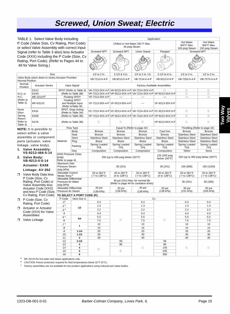
TABLE 1. Select Valve Body including P Code (Valve Size, Cv Rating, Port Code) or select Valve Assembly with correct Input Signal (refer to Table 3 also) less Actuator Code (XXX) including the P Code (Size, Cv Rating, Port Code). (Refer to Pages 44 to 49 for Valve Sizing.)
Application
Chilled or Hot Water 281
°
F Max.35 psig Steam
Hot Water 300
°
F Max.100 psig Steam
Hot Water366
°
F Max.150 psig Steam
Screwed NPT Screwed NPT Union Sweat Flanged Screwed NPT
Size 1/2 to 2 in. 2-1/2 & 3 in. 1/2 to 2 in. I.D. 2-1/2 to 6 in. 1/2 to 2 in. 1/2 to 2 in.Valve Body (stem down to close) Actuator Provides Normal Position VB-7213-0-4-P VB-9213-0-4-P VB-7214-0-4-P VB-9213-0-5-P VB-7253-0-4-P VB-7273-0-4-P
Normal Position Actuator Series Input Signal Factory Available Assemblies
N.O. or N.C.(Refer to Table 3)
EA12 SPST (Refer to Table 3) VA-7213-3XX-4-P VA-9213-3XX-4-P VA-7214-3XX-4-P
EA4X (Refer to Table 3B) VP-7213-3XX-4-P VP-9213-3XX-4-P VA-7214-3XX-4-P VP-9213-3XX-5-P
MF-221X3
a
Floating SPDT VF-7213-25X-4-P –– — –– — —
MF-631X3Floating SPDT
and Multiple Input (Refer toTable 3D
VF-7213-30X-4-P VF-9213-30X-4-P –– VF-9213-30X-5-P
None(Non-Spring Return. Refer to Table 3)
EA31 SPDT, Snap Acting (Refer to Table 3A) VC-7213-4XX-4-P VC-9213-4XX-4-P VA-7214-4XX-4-P VC-9213-4XX-5-P
EA58 (Refer to Table 3B) VP-7213-4XX-4-P VP-9213-4XX-4-P VA-7214-4XX-4-P VP-9213-4XX-5-P
EA76 (Refer to Table 3B)
VP-9213-9XX-5-P
NOTE:
It is possible to select either a valve assembly or component parts (actuator, valve linkage, valve body).
1. Valve Assembly: VS-9213-466-5-14
2. Valve Body: VB-9213-0-5-14Actuator: EA58Linkage: AV-352
Valve Body Data less P Code (Size, Cv Rating, Port Code) or Valve Assembly less Actuator Code (XXX) and less P Code (Size, Cv Rating, Port Code)
P Code (Size, Cv Rating, Port Code)
Actuator or Actuator Code (XXX) for Valve Assemblies
Valve Linkage
Flow Type Equal % (Refer to page 42) Throttling (Refer to page 42)
Material
Body Bronze Bronze Bronze Cast Iron Bronze BronzeSeat Bronze Bronze Bronze Bronze Stainless Steel Stainless SteelStem Stainless Steel Stainless Steel Stainless Steel Stainless Steel Stainless Steel Stainless SteelPlug Brass Brass Brass Brass Stainless Steel Stainless Steel
Packing Spring Loaded TFE
Spring Loaded TFE
Spring Loaded TFE
Spring Loaded TFE
Spring Loaded TFE
Spring Loaded TFE
Disc Composition Composition Composition Composition Teflon NoneANSI Pressure Class (psig)Refer to page 41
250 (up to 400 psig below 150
°
F)125 (200 psig below 150
°
F) 250 (up to 400 psig below 150
°
F)
Maximum Inlet Pressure Steam psig (kPa)
35 (241) 35 (241) 100 (690) 150 (1034)
Allowable Control Media Temp
b
20 to 281
°
F(-7 to 138
°
C)40 to 281
°
F(4 to 138
°
C)20 to 281
°
F(-7 to 138
°
C)40 to 281
°
F(4 to 138
°
C)20 to 281
°
F(-7 to 138
°
C)20 to 281
°
F(-7 to 138
°
C)Allowable Differential Pressure for Waterpsig (kPa)
35 psi (241) Max. for normal life (Refer to page 44 for cavitation limits)
35 (241) 50 (345)
Allowable Differential Pressure for Steam
20 psi(138 kPa)
20 psi(138 kPa)
20 psi(138 kPa)
20 psi(138 kPa)
35 psi(241 kPa)
50 psi(345 kPa)
TO SELECT A PORT CODE (P).
P Code
Valve Size in.
Cv-1
c
1/2
0.4
0.4
0.4 0.4
-2
c
1.3 1.3 1.3 1.3
-3
c
2.2 2.2 2.2 2.2-4 4.4 4.4 4.4 4.4
-5
c
3/4
5.5 5.5 5.5 5.5-6 7.5 7.5 7.5 7.5
-7
c
1
10 10 10 10-8 14 14 14 14-9
1-1/4
20 20 20 20-10
1-1/2
30 30 30 30-11
2
40 40 40 40-12
2-1/2
65
56
-13
3
85 85-14
4
145-15
5
235-16
6
350
SweaElec
Two Way
Valves
1323-DB-001-0-01 Barber-Colman Company, Loves Park, IL Page 16
Screwed, Union Sweat; Electric
Tw
o W
ayV
alve
s
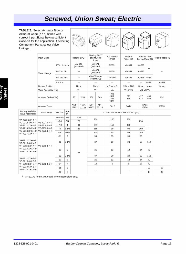
a MF-221X3 for hot water and steam applications only.
TABLE 2. Select Actuator Type or Actuator Code (XXX) series with correct Input Signal having sufficient close-off for the application. If selecting Component Parts, select Valve Linkage.
Input Signal Floating SPDTFloating SPDT and Multiple
Input
Two-Position SPST
Refer to Table 3B
Refer to Table 3A, andTable 3B Refer to Table 3B
Valve Linkage
1/2 to 1-1/4 in. AV-640(Included)
AV-671(Included) AV-391 AV-391 AV-393
—
–1-1/2 to 2 in. — AV-671(Included) AV-391 AV-391 AV-393
2-1/2 to 4 in. — AV-672 (order separately) AV-395 AV-395 AV-396 AV-352
5 to 6 in. — — — — — AV-352 AV-358
Normal Position None None N.O. or N.C. N.O. or N.C. None None None
Valve Assembly Type VF VF VA VP or VS VC, VP, VS –
Actuator Code (XXX) 251 253 301 303
301311321322
317318
417423
465466 952
Actuator Typesa MF-22103
a MF-22123
MF-63103
MF-63123 EA12 EA4X EA31
EA58 EA76
Factory Available Valve Assemblies Valve Body P Code Size
in. CLOSE-OFF PRESSURE RATING (psi)
VA-7213-3XX-4-PVC-7213-4XX-4-PVF-7213-2XX-4-PVP-7213-XXX-4-PVS-7213-XXX-4-PVF-7213-3XX-4-P
VB-7213-0-4-PVB-7214-0-4-PVB-7253-0-4-PVB-7273-0-4-P
-1-2-3-4 1/2 170250 250 250
250
—
–
-5-6 3/4 76
-7-8 1 41 241 150 150
-9 1-1/4 26 156 90 90 200
-10 1-1/2
—
105 65 65 140
-11 2 59 35 35 80
VA-9213-3XX-4-PVC-9213-4XX-4-PVF-9213-3XX-4-PVP-9213-XXX-4-PVS-9213-XXX-4-P
VB-9213-0-4-P
-12 2-1/2 37 20 20 50 112
-13 3 25 12 12 34 77
VA-9213-3XX-5-PVC-9213-4XX-5-PVF-9213-3XX-5-PVP-9213-5XX-5-PVS-9213-XXX-5-P
VB-9213-0-5-P
-12 2-1/2 37 20 20 50 112
-13 3 25 12 12 34 77
-14 4 14 6 6 17 42
-15 5— — — —
20 67
-16 6 14 46
Screwed, Union Sweat; Electric
1323-DB-001-0-01 Barber-Colman Company, Loves Park, IL Page 17
Two
Way
Val
ves
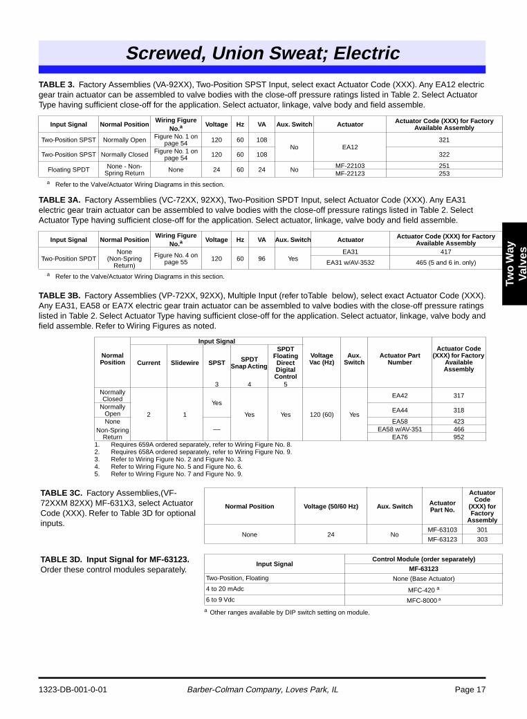
TABLE 3. Factory Assemblies (VA-92XX), Two-Position SPST Input, select exact Actuator Code (XXX). Any EA12 electric gear train actuator can be assembled to valve bodies with the close-off pressure ratings listed in Table 2. Select Actuator Type having sufficient close-off for the application. Select actuator, linkage, valve body and field assemble.
TABLE 3A. Factory Assemblies (VC-72XX, 92XX), Two-Position SPDT Input, select Actuator Code (XXX). Any EA31 electric gear train actuator can be assembled to valve bodies with the close-off pressure ratings listed in Table 2. Select Actuator Type having sufficient close-off for the application. Select actuator, linkage, valve body and field assemble.
TABLE 3B. Factory Assemblies (VP-72XX, 92XX), Multiple Input (refer toTable below), select exact Actuator Code (XXX). Any EA31, EA58 or EA7X electric gear train actuator can be assembled to valve bodies with the close-off pressure ratings listed in Table 2. Select Actuator Type having sufficient close-off for the application. Select actuator, linkage, valve body and field assemble. Refer to Wiring Figures as noted.
a Refer to the Valve/Actuator Wiring Diagrams in this section.
a Refer to the Valve/Actuator Wiring Diagrams in this section.
a Other ranges available by DIP switch setting on module.
Input Signal Normal PositionWiring Figure
No.aVoltage Hz VA Aux. Switch Actuator Actuator Code (XXX) for Factory
Available Assembly
Two-Position SPST Normally Open Figure No. 1 on page 54 120 60 108
No EA12321
Two-Position SPST Normally Closed Figure No. 1 on page 54 120 60 108 322
Floating SPDT None - Non-Spring Return None 24 60 24 No
MF-22103 251MF-22123 253
Input Signal Normal PositionWiring Figure
No.aVoltage Hz VA Aux. Switch Actuator Actuator Code (XXX) for Factory
Available Assembly
Two-Position SPDTNone
(Non-Spring Return)
Figure No. 4 on page 55 120 60 96 Yes
EA31 417
EA31 w/AV-3532 465 (5 and 6 in. only)
Normal Position
Input Signal
VoltageVac (Hz)
Aux. Switch
Actuator Part Number
Actuator Code (XXX) for Factory
Available Assembly
Current Slidewire SPST SPDT Snap Acting
SPDT Floating Direct Digital Control
3 4 5Normally Closed
2 1
Yes
Yes Yes 120 (60) Yes
EA42 317
Normally Open EA44 318
NoneNon-Spring
Return––
EA58 423EA58 w/AV-351 466
EA76 9521. Requires 659A ordered separately, refer to Wiring Figure No. 8.2. Requires 658A ordered separately, refer to Wiring Figure No. 9.3. Refer to Wiring Figure No. 2 and Figure No. 3.4. Refer to Wiring Figure No. 5 and Figure No. 6.5. Refer to Wiring Figure No. 7 and Figure No. 9.
TABLE 3C. Factory Assemblies,(VF-72XXM 82XX) MF-631X3, select Actuator Code (XXX). Refer to Table 3D for optional inputs.
Normal Position Voltage (50/60 Hz) Aux. Switch Actuator Part No.
Actuator Code
(XXX) for Factory
Assembly
None 24 NoMF-63103 301
MF-63123 303
TABLE 3D. Input Signal for MF-63123. Order these control modules separately.
Input SignalControl Module (order separately)
MF-63123Two-Position, Floating None (Base Actuator)
4 to 20 mAdc MFC-420 a
6 to 9 Vdc MFC-8000 a

1323-DB-001-0-01 Barber-Colman Company, Loves Park, IL Page 18
Screwed, Union Sweat; Electric
Tw
o W
ayV
alve
s
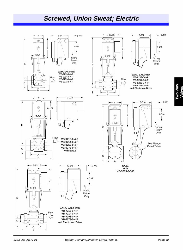
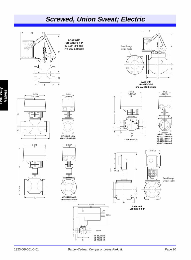
TABLE 4. Dimensions in Inches (Millimeters). (Refer to pages 18 through 19 for illustrations.)
TABLE 5. Dimensions in Inches (Millimeters). (Refer to pages 18 through 19 for illustrations.)
a Use B dimension for VB-7214.b Subtract 3/4 in. on MA actuators.
a MF-221X3 for hot water and steam applications only.b Use B dimension for VB-7214.
Valve BodyActuator Series (Code)
EA12 EA31 EA58 EA76Part Number Size In. A Ba C Eb E E E
VB-7213-0-4-PVB-7214-0-4-PVB-7253-0-4-PVB-7273-0-4-P
1/2 3 (76) 4-1/4 (108) 1-7/16 (36) 12-13/16 (325) 13-11/16 (347) 13-11/16 (347)3/4 3-5/8 (92) 5-1/2 (140) 1-7/16 (36) 13-7/16 (351) 14-11/16 (373) 14-11/16 (373)1
4-5/8 (117)6-3/4 (171) 2-1/8 (53) 14-1/8 (358) 15 (380) 15 (380)
1-1/4 6-7/8 (175) 1-7/8 (48) 13-11/16 (347) 14-9/16 (369) 14-9/16 (369)1-1/2 5-3/8 (137) 8-5/8 (219)
1-7/8 (48)13-3/4 (349) 14-5/8 (371) 14-5/8 (371)
2 6-1/8 (156) 9-3/16 (233) 14 (355) 14-7/8 (377) 14-7/8 (377)
VB-9213-0-4-P 2-1/2 8-1/2 (216) 3-3/4 (95) 16-1/4 (413) 16-1/4 (413) 15-1/4 (387)3 9-1/2 (241) 4-1/4 (108) 16-7/16 (418) 16-7/16 (418) 15-7/16 (392)
VB-9213-0-5-P
2-1/2 8-1/2 (216) 3-1/2 (89) 16-1/4 (413) 16-1/4 (413) 15-1/4 (387)3 9-1/2 (241) 3-3/4 (95) 16-5/8 (422) 16-5/8 (422) 15-5/8 (397)4 11-1/2 (292) 4-1/2 (114) 17-7/8 (454) 17-7/8 (454) 16-7/8 (429) 23 (584)5 13 (330) 5 (127) 18-1/8 (460) 24-1/4 (616)6 14 (356) 5-1/2 (140) 18-5/8 (473) 25-1/8 (638)
Valve BodyActuator Series (Code)
MF-221X3 a MF-631X3
Part Number Size In. A Bb C E E
VB-7213-0-4-PVB-7214-0-4-PVB-7253-0-4-PVB-7273-0-4-P
1/2 3 (76) 4-1/4 (108) 1-7/16 (36) 4-1/4 (107) 7 (177)3/4 3-5/8 (92) 5-1/2 (140) 1-7/16 (36) 5-1/4 (133) 8 (203)1
4-5/8 (117)6-3/4 (171) 2-1/8 (53) 5-1/2 (140) 8-5/16 (210)
1-1/4 6-7/8 (175) 1-7/8 (48) 5-1/16 (129) 7-7/8 (199)1-1/2 5-3/8 (137) 8-5/8 (219)
1-7/8 (48)4-7/8 (124) 7-15/16 (201)
2 6-1/8 (156) 9-3/16 (233) 5-7/16 (137) 8-3/16 (207)
VB-9213-0-4-P 2-1/2 8-1/2 (216) 3-3/4 (95) 13-13/16 (351)3 9-1/2 (241) 4-1/4 (108) 14-1/16 (357)
VB-9213-0-5-P2-1/2 8-1/2 (216) 3-1/2 (89) 13-7/8 (352)
3 9-1/2 (241) 3-3/4 (95) 14-1/4 (362)4 11-1/2 (292) 4-1/2 (114) 15-1/2 (394)
6-1/4
7-1/8
E
C
4
5-3/8
AB
FlowVB-7214-0-4-P VB-7253-0-4-P VB-7273-0-4-P
with EA12
7
6-3/4 1-7/8
4-1/4
E
C
4
5-3/8
AB
Spring Return Only
Flow
EA31 with VB-7214-0-4-P VB-7253-0-4-P VB-7273-0-4-P
Screwed, Union Sweat; Electric
1323-DB-001-0-01 Barber-Colman Company, Loves Park, IL Page 19
Two
Way
Val
ves
6-1/4
7-1/8
E
C
4
5-3/8
AB
A A
BB
Flow VB-9213-0-4-P VB-9214-0-4-P VB-9253-0-4-P VB-9273-0-4-P
with EA12
Refer to Table 4 and Table 5 for dimensional data.
AB
6-3/4 1-7/8
4-1/4
E
5-3/8
C
Spring Return Only
7
6-13/16
Flow
EA4X, EA5X with VB-7213-0-4-P VB-7214-0-4-P VB-7253-0-4-P VB-7273-0-4-P
and Electronic DriveA B
A
7
6-3/4 1-7/8
4-1/4
E
C
4
5-3/8
AB
A A
BB
Spring Return Only
Flow
EA4X, EA5X with VB-9213-0-4-P VB-9214-0-4-P VB-9253-0-4-P VB-9273-0-4-P
E
A
6-3/4
A A
BB
7
4
5-3/8
C
EA31 with
VB-9213-0-5-P
See Flange Detail Table
1-7/8
4-1/4
Spring Return Only
AB
6-3/4 1-7/8
4-1/4
E
5-3/8
C
Spring Return Only
7
6-13/16
Flow
EA4X, EA5X with VB-9213-0-4-P VB-9214-0-4-P VB-9253-0-4-P VB-9273-0-4-P
and Electronic DriveA B
A
1323-DB-001-0-01 Barber-Colman Company, Loves Park, IL Page 20
Screwed, Union Sweat; Electric
Tw
o W
ayV
alve
s
E
C
A
3-5/8"
MF-631X3 with VB-9213-000-5-P
5-5/8"
E
C
9-9/16
9-7/8
A
EA76 with VB-9213-0-5-P
See Flange Detail Table
E
C
A
B*
5-5/8 (143mm)
MF-631X3 with VB-7213-000-4-P VB-7214-000-4-P VB-7253-000-4-P VB-7273-000-4-P
3-5/8 (92mm)
* For VB-7214
5-5/64
3-3/16
E
C
MF-221X3 with VB-7213-0-4-P VB-7214-0-4-P
FLOW
AB
E
C
A
B*
5-5/8 (143mm)
MF-631X3 with VB-9213-000-4-P
3-5/8 (92mm)
E
C
A
9
EA58 with VB-9213-0-5-P
and AV-352 Linkage
See Flange Detail Table
9
E
A
C
A AB
EA58 with VB-9213-0-4-P (2-1/2"–3") and AV-352 Linkage
Screwed, Union Sweat; Electric
1323-DB-001-0-01 Barber-Colman Company, Loves Park, IL Page 21
Two
Way
Val
ves
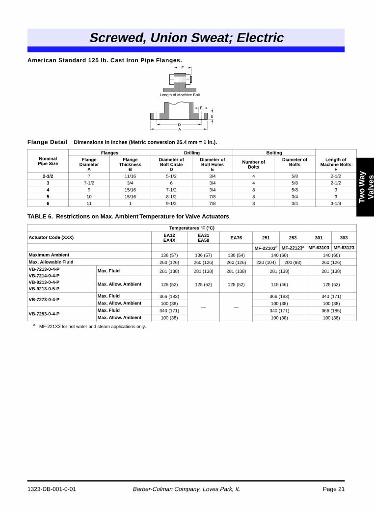
American Standard 125 lb. Cast Iron Pipe Flanges.
Flange Detail Dimensions in Inches (Metric conversion 25.4 mm = 1 in.).
TABLE 6. Restrictions on Max. Ambient Temperature for Valve Actuators.
a MF-221X3 for hot water and steam applications only.
NominalPipe Size
Flanges Drilling Bolting
FlangeDiameter
A
FlangeThickness
B
Diameter ofBolt Circle
D
Diameter ofBolt Holes
E
Number of Bolts
Diameter ofBolts
Length ofMachine Bolts
F
2-1/2 7 11/16 5-1/2 3/4 4 5/8 2-1/2
3 7-1/2 3/4 6 3/4 4 5/8 2-1/2
4 9 15/16 7-1/2 3/4 8 5/8 3
5 10 15/16 8-1/2 7/8 8 3/4 3
6 11 1 9-1/2 7/8 8 3/4 3-1/4
Temperatures °F (°C)
Actuator Code (XXX) EA12EA4X
EA31EA58 EA76 251 253 301 303
MF-22103a MF-22123a MF-63103 MF-63123
Maximum Ambient 136 (57) 136 (57) 130 (54) 140 (60) 140 (60)
Max. Allowable Fluid 260 (126) 260 (126) 260 (126) 220 (104) 200 (93) 260 (126)
VB-7213-0-4-PVB-7214-0-4-PVB-9213-0-4-PVB-9213-0-5-P
Max. Fluid 281 (138) 281 (138) 281 (138) 281 (138) 281 (138)
Max. Allow. Ambient 125 (52) 125 (52) 125 (52) 115 (46) 125 (52)
VB-7273-0-4-PMax. Fluid 366 (183)
— —
366 (183) 340 (171)
Max. Allow. Ambient 100 (38) 100 (38) 100 (38)
VB-7253-0-4-PMax. Fluid 340 (171) 340 (171) 366 (185)
Max. Allow. Ambient 100 (38) 100 (38) 100 (38)
D
Length of Machine Bolt
A
E
B
F
1323-DB-001-0-01 Barber-Colman Company, Loves Park, IL Page 22
High Temp; Electric
Tw
o W
ayV
alve
s
a CAUTION: Maximum recommended differential pressure in full open position. Do not exceed recommended differential pressure (pressure drop) or integrity of parts may be affected. Do not exceed close-off rating.
b CAUTION: Fittings and/or pipe schedules must meet or exceed working static pressure requirements.
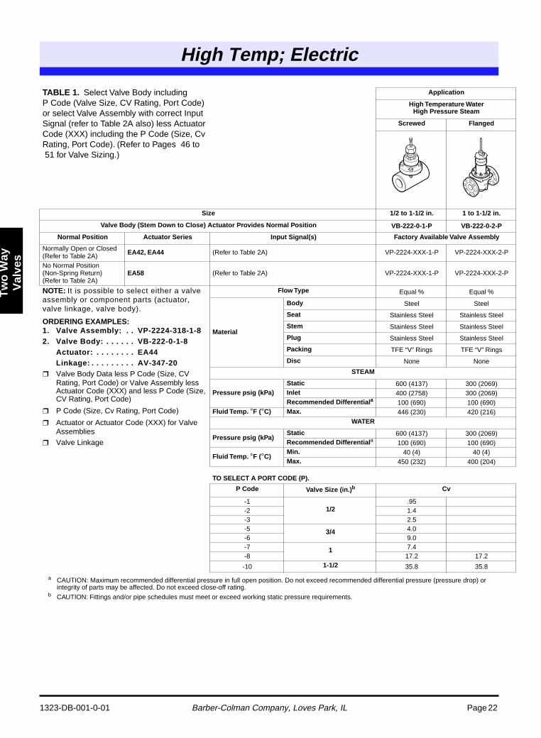
TABLE 1. Select Valve Body including P Code (Valve Size, CV Rating, Port Code) or select Valve Assembly with correct Input Signal (refer to Table 2A also) less Actuator Code (XXX) including the P Code (Size, Cv Rating, Port Code). (Refer to Pages 46 to 51 for Valve Sizing.)
Application
High Temperature WaterHigh Pressure Steam
Screwed Flanged
Size 1/2 to 1-1/2 in. 1 to 1-1/2 in.
Valve Body (Stem Down to Close) Actuator Provides Normal Position VB-222-0-1-P VB-222-0-2-P
Normal Position Actuator Series Input Signal(s) Factory Available Valve Assembly
Normally Open or Closed (Refer to Table 2A) EA42, EA44 (Refer to Table 2A) VP-2224-XXX-1-P VP-2224-XXX-2-P
No Normal Position (Non-Spring Return) (Refer to Table 2A)
EA58 (Refer to Table 2A) VP-2224-XXX-1-P VP-2224-XXX-2-P
NOTE: It is possible to select either a valve assembly or component parts (actuator, valve linkage, valve body).
ORDERING EXAMPLES:1. Valve Assembly: . . VP-2224-318-1-82. Valve Body: . . . . . . VB-222-0-1-8
Actuator: . . . . . . . . EA44Linkage: . . . . . . . . . AV-347-20
Valve Body Data less P Code (Size, CV Rating, Port Code) or Valve Assembly less Actuator Code (XXX) and less P Code (Size, CV Rating, Port Code)
P Code (Size, Cv Rating, Port Code)
Actuator or Actuator Code (XXX) for Valve Assemblies
Valve Linkage
Flow Type Equal % Equal %
Material
Body Steel Steel
Seat Stainless Steel Stainless Steel
Stem Stainless Steel Stainless Steel
Plug Stainless Steel Stainless Steel
Packing TFE “V” Rings TFE “V” Rings
Disc None None
STEAM
Pressure psig (kPa)Static 600 (4137) 300 (2069)Inlet 400 (2758) 300 (2069)Recommended Differentiala 100 (690) 100 (690)
Fluid Temp. °F (°C) Max. 446 (230) 420 (216)WATER
Pressure psig (kPa)Static 600 (4137) 300 (2069)Recommended Differentiala 100 (690) 100 (690)
Fluid Temp. °F (°C)Min. 40 (4) 40 (4)Max. 450 (232) 400 (204)
TO SELECT A PORT CODE (P).
P Code Valve Size (in.)b Cv
-11/2
.95-2 1.4-3 2.5-5 3/4 4.0-6 9.0-7 1 7.4-8 17.2 17.2
-10 1-1/2 35.8 35.8
igh emp; lectric
Two
High Temp; Electric
1323-DB-001-0-01 Barber-Colman Company, Loves Park, IL Page 23
Tw
o W
ay
Val
ves
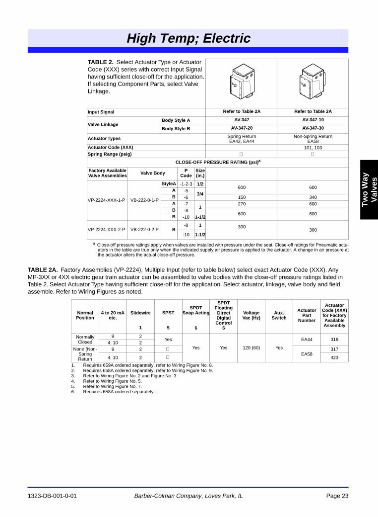
TABLE 2A. Factory Assemblies (VP-2224), Multiple Input (refer to table below) select exact Actuator Code (XXX). Any MP-3XX or 4XX electric gear train actuator can be assembled to valve bodies with the close-off pressure ratings listed in Table 2. Select Actuator Type having sufficient close-off for the application. Select actuator, linkage, valve body and field assemble. Refer to Wiring Figures as noted.
a Close-off pressure ratings apply when valves are installed with pressure under the seat. Close-off ratings for Pneumatic actu-ators in the table are true only when the indicated supply air pressure is applied to the actuator. A change in air pressure atthe actuator alters the actual close-off pressure.
TABLE 2. Select Actuator Type or Actuator Code (XXX) series with correct Input Signal having sufficient close-off for the application. If selecting Component Parts, select Valve Linkage.
Input Signal Refer to Table 2A Refer to Table 2A
Valve LinkageBody Style A AV-347 AV-347-10
Body Style B AV-347-20 AV-347-30
Actuator Types Spring ReturnEA42, EA44
Non-Spring ReturnEA58
Actuator Code (XXX) 101, 103Spring Range (psig)
CLOSE-OFF PRESSURE RATING (psi)a
Factory Available Valve Assemblies Valve Body P
CodeSize (in.)
VP-2224-XXX-1-P VB-222-0-1-P
StyleA -1-2-3 1/2600 600
A -53/4
B -6 150 340A -7
1270 600
B -8600 600
B -10 1-1/2
VP-2224-XXX-2-P VB-222-0-2-P B-8 1 300
300-10 1-1/2
Normal Position
4 to 20 mA etc.
Slidewire
1
SPST
5
SPDT Snap Acting
6
SPDT Floating Direct Digital Control
6
VoltageVac (Hz)
Aux.Switch
Actuator Part
Number
Actuator Code (XXX) for Factory Available Assembly
Normally Closed
9 2Yes
Yes Yes 120 (60) Yes
EA44 3184, 10 2
None (Non-Spring Return
9 2 EA58
317
4, 10 2 423
1. Requires 659A ordered separately, refer to Wiring Figure No. 8.2. Requires 658A ordered separately, refer to Wiring Figure No. 9.3. Refer to Wiring Figure No. 2 and Figure No. 3.4. Refer to Wiring Figure No. 5.5. Refer to Wiring Figure No. 7.6. Requires 658A ordered separately..
1323-DB-001-0-01 Barber-Colman Company, Loves Park, IL Page 24
High Temp; Electric
Tw
o W
ayV
alve
s
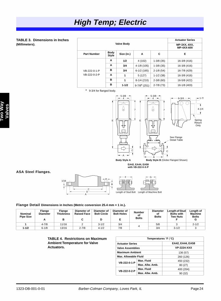
ASA Steel Flanges.
Flange Detail Dimensions in Inches (Metric conversion 25.4 mm = 1 in.).
a 9-3/4 for flanged body.
TABLE 3. Dimensions in Inches(Millimeters). Valve Body
Actuator Series
MP-3XX, 4XX,MP-4XX-600
Part Number Body Style Size (in.) A C E
VB-222-0-1-PVB-222-0-2-P
A 1/2 4 (102) 1-3/8 (35) 16-3/8 (416)
A 3/4 4-1/8 (105) 1-3/8 (35) 16-3/8 (416)
B 3/4 6-1/2 (165) 2-1/8 (54) 16-7/8 (429)
A 1 5 (127) 1-1/2 (38) 16-3/8 (416)
B 1 8-1/4 (210) 2-3/8 (60) 16-5/8 (422)
B 1-1/2 9-7/8a (251) 2-7/8 (73) 16-1/8 (403)
NominalPipe Size
FlangeDiameter
A
FlangeThickness
B
Diameter of Raised Face
C
Diameter ofBolt Circle
D
Diameter ofBolt Holes
E
Numberof
Bolts
Diameterof
Bolts
Length of Stud Bolts with Two Nuts
F
Length of Machine
BoltsG
1 4-7/8 11/16 2 3-1/2 3/44
5/8 3 2-1/21-1/2 6-1/8 13/16 2-7/8 4-1/2 7/8 3/4 3-1/2 3
TABLE 4. Restrictions on Maximum Ambient Temperature for Valve Actuators.
Temperatures °F (°C)
Actuator Series EA42, EA44, EA58
Valve Assemblies VP-2224-XXX
Maximum Ambient 136 (57)
Max. Allowable Fluid 260 (126)
VB-222-0-1-PMax. Fluid 450 (232)
Max. Allw. Amb. 80 (27)
VB-222-0-2-PMax. Fluid 400 (204)
Max. Allw. Amb. 90 (32)
E
7
45-3/8
E
6-3/4
A
4-1/4
Spring Return Only
See Flange Detail Table
1-7/8
CC
A
7
45-3/8
Body Style A
EA42, EA44, EA58 with VB-222-0-X-P
Body Style B (Globe Flanged Shown)
C
B
EF G
DA
Length of Stud Bolt Length of Machine Bolt
1/16
Mixing, Sequencing; Flared
1323-DB-001-0-01 Barber-Colman Company, Loves Park, IL Page 25
Th
ree
Way
Val
ves
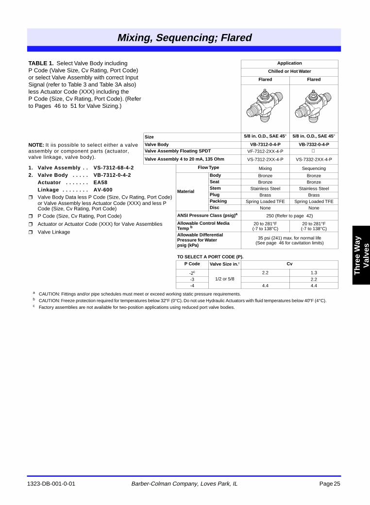
a CAUTION: Fittings and/or pipe schedules must meet or exceed working static pressure requirements.b CAUTION: Freeze protection required for temperatures below 32°F (0°C). Do not use Hydraulic Actuators with fluid temperatures below 40°F (4°C).c Factory assemblies are not available for two-position applications using reduced port valve bodies.
TABLE 1. Select Valve Body including P Code (Valve Size, Cv Rating, Port Code) or select Valve Assembly with correct Input Signal (refer to Table 3 and Table 3A also) less Actuator Code (XXX) including the P Code (Size, Cv Rating, Port Code). (Refer to Pages 46 to 51 for Valve Sizing.)
Application
Chilled or Hot Water
Flared Flared
Size 5/8 in. O.D., SAE 45° 5/8 in. O.D., SAE 45°
NOTE: It iis possible to select either a valve assembly or component parts (actuator, valve linkage, valve body).
Valve Body VB-7312-0-4-P VB-7332-0-4-PValve Assembly Floating SPDT VF-7312-2XX-4-P
Valve Assembly 4 to 20 mA, 135 Ohm VS-7312-2XX-4-P VS-7332-2XX-4-P
1. Valve Assembly . . VS-7312-68-4-22. Valve Body . . . . . VB-7312-0-4-2
Actuator . . . . . . . EA58Linkage . . . . . . . . AV-600
Valve Body Data less P Code (Size, Cv Rating, Port Code) or Valve Assembly less Actuator Code (XXX) and less P Code (Size, Cv Rating, Port Code)
P Code (Size, Cv Rating, Port Code)
Actuator or Actuator Code (XXX) for Valve Assemblies
Valve Linkage
Flow Type Mixing Sequencing
Material
Body Bronze BronzeSeat Bronze BronzeStem Stainless Steel Stainless SteelPlug Brass BrassPacking Spring Loaded TFE Spring Loaded TFEDisc None None
ANSI Pressure Class (psig)a 250 (Refer to page 42)
Allowable Control Media Temp b
20 to 281°F (-7 to 138°C)
20 to 281°F(-7 to 138°C)
Allowable Differential Pressure for Waterpsig (kPa)
35 psi (241) max. for normal life (See page 46 for cavitation limits)
TO SELECT A PORT CODE (P).
P Code Valve Size in.c Cv
-2c
1/2 or 5/82.2 1.3
-3 2.2-4 4.4 4.4
Mixing,
Sequencing; Flared
Mixing, Sequencing; Flared
1323-DB-001-0-01 Barber-Colman Company, Loves Park, IL Page 26
Th
ree
Way
Val
ves
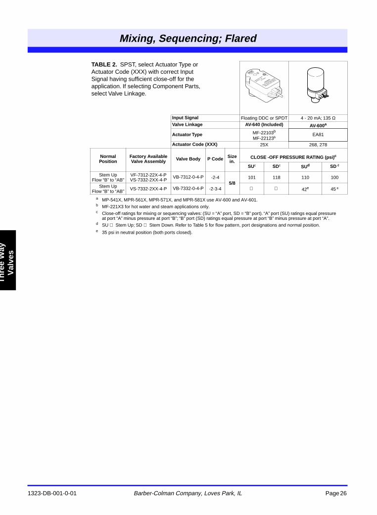
a MP-541X, MPR-561X, MPR-571X, and MPR-581X use AV-600 and AV-601.b MF-221X3 for hot water and steam applications only.c Close-off ratings for mixing or sequencing valves: (SU = “A” port, SD = “B” port). “A” port (SU) ratings equal pressure
at port “A” minus pressure at port “B”; “B” port (SD) ratings equal pressure at port “B” minus pressure at port “A”.d SU Stem Up; SD Stem Down. Refer to Table 5 for flow pattern, port designations and normal position.e 35 psi in neutral position (both ports closed).
TABLE 2. SPST, select Actuator Type or Actuator Code (XXX) with correct Input Signal having sufficient close-off for the application. If selecting Component Parts, select Valve Linkage.
Input Signal Floating DDC or SPDT 4 - 20 mA; 135 ΩValve Linkage AV-640 (Included) AV-600a
Actuator Type MF-22103b
MF-22123bEA81
Actuator Code (XXX) 25X 268, 278
Normal Position
Factory Available Valve Assembly Valve Body P Code Size
in.CLOSE -OFF PRESSURE RATING (psi)c
SUc SDc SUd SD d
Stem Up Flow “B” to “AB”
VF-7312-22X-4-P VS-7332-2XX-4-P
VB-7312-0-4-P -2-45/8
101 118 110 100
Stem Up Flow “B” to “AB” VS-7332-2XX-4-P VB-7332-0-4-P -2-3-4 42e 45 e
Mixing, Sequencing; Flared
1323-DB-001-0-01 Barber-Colman Company, Loves Park, IL Page 27
Th
ree
Way
Val
ves
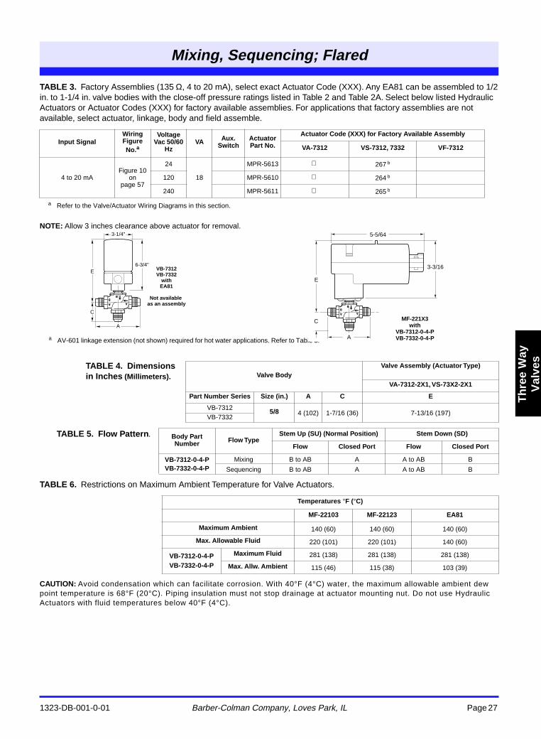
TABLE 3. Factory Assemblies (135 Ω, 4 to 20 mA), select exact Actuator Code (XXX). Any EA81 can be assembled to 1/2 in. to 1-1/4 in. valve bodies with the close-off pressure ratings listed in Table 2 and Table 2A. Select below listed Hydraulic Actuators or Actuator Codes (XXX) for factory available assemblies. For applications that factory assemblies are not available, select actuator, linkage, body and field assemble.
NOTE: Allow 3 inches clearance above actuator for removal.
TABLE 6. Restrictions on Maximum Ambient Temperature for Valve Actuators.
CAUTION: Avoid condensation which can facilitate corrosion. With 40°F (4°C) water, the maximum allowable ambient dew point temperature is 68°F (20°C). Piping insulation must not stop drainage at actuator mounting nut. Do not use Hydraulic Actuators with fluid temperatures below 40°F (4°C).
a Refer to the Valve/Actuator Wiring Diagrams in this section.
Input SignalWiring Figure No.a
Voltage Vac 50/60
HzVA Aux.
SwitchActuator Part No.
Actuator Code (XXX) for Factory Available Assembly
VA-7312 VS-7312, 7332 VF-7312
4 to 20 mAFigure 10
on page 57
24
18
MPR-5613 267 b
120 MPR-5610 264 b
240 MPR-5611 265 b
TABLE 4. Dimensions in Inches (Millimeters). Valve Body
Valve Assembly (Actuator Type)
VA-7312-2X1, VS-73X2-2X1
Part Number Series Size (in.) A C E
VB-7312 5/8 4 (102) 1-7/16 (36) 7-13/16 (197)VB-7332
TABLE 5. Flow Pattern. Body Part Number Flow Type
Stem Up (SU) (Normal Position) Stem Down (SD)
Flow Closed Port Flow Closed Port
VB-7312-0-4-PVB-7332-0-4-P
Mixing B to AB A A to AB B
Sequencing B to AB A A to AB B
Temperatures °F (°C)
MF-22103 MF-22123 EA81
Maximum Ambient 140 (60) 140 (60) 140 (60)
Max. Allowable Fluid 220 (101) 220 (101) 140 (60)
VB-7312-0-4-PVB-7332-0-4-P
Maximum Fluid 281 (138) 281 (138) 281 (138)
Max. Allw. Ambient 115 (46) 115 (38) 103 (39)
a AV-601 linkage extension (not shown) required for hot water applications. Refer to Table 3.
3-1/4"
6-3/4"E
C
A
VB-7312 VB-7332
with EA81
Not available
as an assembly
5-5/64
3-3/16
E
C MF-221X3 with
VB-7312-0-4-P VB-7332-0-4-PA
Mixing, Diverting; Hydraulic
1323-DB-001-0-01
Barber-Colman Company, Loves Park, IL
Page 28
T
hre
e W
ayV
alve
s
a
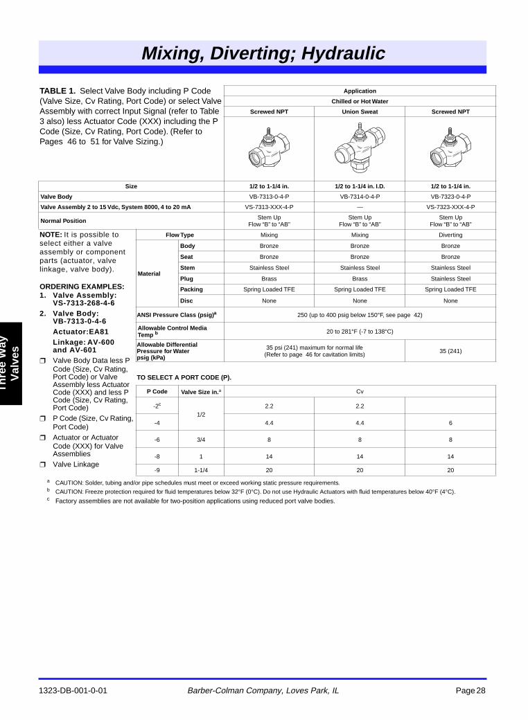
CAUTION: Solder, tubing and/or pipe schedules must meet or exceed working static pressure requirements.
b
CAUTION: Freeze protection required for fluid temperatures below 32
°
F (0
°
C). Do not use Hydraulic Actuators with fluid temperatures below 40
°
F (4
°
C).
c
Factory assemblies are not available for two-position applications using reduced port valve bodies.
TABLE 1.
Select Valve Body including P Code (Valve Size, Cv Rating, Port Code) or select Valve Assembly with correct Input Signal (refer to Table 3 also) less Actuator Code (XXX) including the P Code (Size, Cv Rating, Port Code). (Refer to Pages 46 to 51 for Valve Sizing.)
Application
Chilled or Hot Water
Screwed NPT Union Sweat Screwed NPT
Size 1/2 to 1-1/4 in. 1/2 to 1-1/4 in. I.D. 1/2 to 1-1/4 in.
Valve Body
VB-7313-0-4-P VB-7314-0-4-P VB-7323-0-4-P
Valve Assembly 2 to 15 Vdc, System 8000, 4 to 20 mA
VS-7313-XXX-4-P — VS-7323-XXX-4-P
Normal Position
Stem Up Flow “B” to “AB”
Stem Up Flow “B” to “AB”
Stem Up Flow “B” to “AB”
NOTE:
It is possible to select either a valve assembly or component parts (actuator, valve linkage, valve body).
ORDERING EXAMPLES:1. Valve Assembly:
VS-7313-268-4-62. Valve Body:
VB-7313-0-4-6Actuator:EA81Linkage: AV-600 and AV-601
Valve Body Data less P Code (Size, Cv Rating, Port Code) or Valve Assembly less Actuator Code (XXX) and less P Code (Size, Cv Rating, Port Code)
P Code (Size, Cv Rating, Port Code)
Actuator or Actuator Code (XXX) for Valve Assemblies
Valve Linkage
Flow Type
Mixing Mixing Diverting
Material
Body
Bronze Bronze Bronze
Seat
Bronze Bronze Bronze
Stem
Stainless Steel Stainless Steel Stainless Steel
Plug
Brass Brass Stainless Steel
Packing
Spring Loaded TFE Spring Loaded TFE Spring Loaded TFE
Disc
None None None
ANSI Pressure Class (psig)
a
250 (up to 400 psig below 150
°
F, see page 42)
Allowable Control Media Temp
b
20 to 281
°
F (-7 to 138
°
C)
Allowable Differential Pressure for Waterpsig (kPa)
35 psi (241) maximum for normal life (Refer to page 46 for cavitation limits) 35 (241)
TO SELECT A PORT CODE (P).
P Code Valve Size in.
a
Cv
-2
c
1/22.2 2.2
-4 4.4 4.4 6
-6 3/4 8 8 8
-8 1 14 14 14
-9 1-1/4 20 20 20
ing, ertin
drauli
Mixing, Diverting; Hydraulic
1323-DB-001-0-01 Barber-Colman Company, Loves Park, IL Page 29
Th
ree
Way
Val
ves
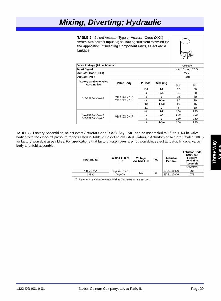
TABLE 3. Factory Assemblies, select exact Actuator Code (XXX). Any EA81 can be assembled to 1/2 to 1-1/4 in. valve bodies with the close-off pressure ratings listed in Table 2. Select below listed Hydraulic Actuators or Actuator Codes (XXX) for factory available assemblies. For applications that factory assemblies are not available, select actuator, linkage, valve body and field assemble.
a Refer to the Valve/Actuator Wiring Diagrams in this section.
TABLE 2. Select Actuator Type or Actuator Code (XXX) series with correct Input Signal having sufficient close-off for the application. If selecting Component Parts, select Valve Linkage.
Valve Linkage (1/2 to 1-1/4 in.) AV-7600Input Signal 4 to 20 mA, 135 ΩActuator Code (XXX) 2XXActuator Type EA81
Factory Available Valve Assemblies Valve Body P Code Size (in.)
SU c SD c
VS-7313-XXX-4-PVB-7313-0-4-P VB-7314-0-4-P
-2-4 1/2 55 80-6 3/4 35 50-8 1 25 30-9 1-1/4 15 20-10 1-1/2 10 15-11 2 6 10
VA-7323-XXX-4-P VS-7323-XXX-4-P
VB-7323-0-4-P
-4 1/2 250 250-6 3/4 250 250-8 1 250 250-9 1-1/4 250 250
Input SignalWiring Figure
No.aVoltage
Vac 50/60 Hz VA Actuator Part No.
Actuator Code (XXX) for Factory
Available AssemblyVS-73X3
4 to 20 mA Figure 10 on page 57 120 18
EA81-11006 268135 Ω EA81-17006 278
Mixing, Diverting; Hydraulic
1323-DB-001-0-01 Barber-Colman Company, Loves Park, IL Page 30
Th
ree
Way
Val
ves
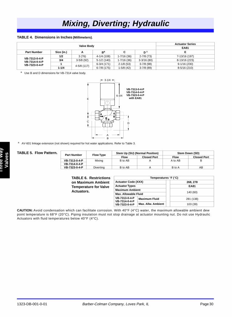
TABLE 4. Dimensions in Inches (Millimeters).
CAUTION: Avoid condensation which can facilitate corrosion. With 40°F (4°C) water, the maximum allowable ambient dew point temperature is 68°F (20°C). Piping insulation must not stop drainage at actuator mounting nut. Do not use Hydraulic Actuators with fluid temperatures below 40°F (4°C).
a Use B and D dimensions for VB-7314 valve body.
Valve BodyActuator Series
EA81Part Number Size (in.) A Ba C D a E
VB-7313-0-4-P VB-7314-0-4-P VB-7323-0-4-P
1/2 3 (76) 4-1/4 (108) 1-7/16 (36) 2-7/8 (73) 7-13/16 (197)3/4 3-5/8 (92) 5-1/2 (140) 1-7/16 (36) 3-3/16 (80) 8-13/16 (223)1
4-5/8 (117)6-3/4 (171) 2-1/8 (53) 3-7/8 (98) 9-1/16 (230)
1-1/4 6-7/8 (175) 1-5/8 (42) 3-7/8 (89) 8-5/16 (210)
TABLE 5. Flow Pattern.Part Number Flow Type
Stem Up (SU) (Normal Position) Stem Down (SD) Flow Closed Port Flow Closed Port
VB-7313-0-4-P Mixing B to AB A A to AB BVB-7314-0-4-PVB-7323-0-4-P Diverting B to AB A B to A AB
TABLE 6. Restrictions on Maximum Ambient Temperature for Valve Actuators.
Temperatures °F (°C)Actuator Code (XXX) 268, 278Actuator Types EA81Maximum Ambient
140 (60)Max. Allowable FluidVB-7313-0-4-P VB-7314-0-4-P VB-7323-0-4-P
Maximum Fluid 281 (138)
Max. Allw. Ambient 103 (39)
3-1/4
6-3/4
D
E
C
BA
VB-7313-0-4-P VB-7314-0-4-P VB-7323-0-4-P
with EA81
a AV-601 linkage extension (not shown) required for hot water applications. Refer to Table 3.
Mixing, Diverting; Electric
1323-DB-001-0-01 Barber-Colman Company, Loves Park, IL Page 31
Th
ree
Way
Val
ves
X
a
Refer to Table 3 and Table 6 for flow pattern, port designations, and normal position.
b
MF-221X3 for hot water and steam applications only.
c
CAUTION: Solder, tubing and/or pipe schedules must meet or exceed working static pressure requirements.
d
CAUTION: Freeze protection required for fluid temperatures below 32
°
F (0
°
C).
e
Factory assemblies are not available for two-position application using reduced port valve bodies.
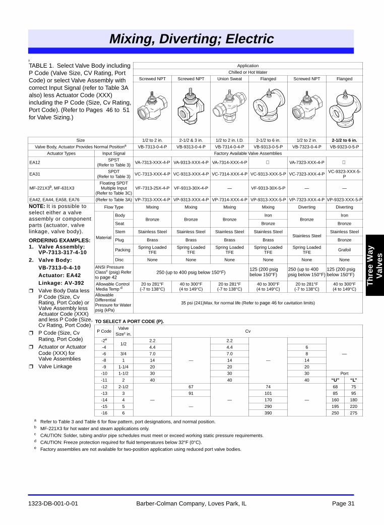
TABLE 1. Select Valve Body including P Code (Valve Size, CV Rating, Port Code) or select Valve Assembly with correct Input Signal (refer to Table 3A also) less Actuator Code (XXX) including the P Code (Size, Cv Rating, Port Code). (Refer to Pages 46 to 51 for Valve Sizing.)
Application
Chilled or Hot Water
Screwed NPT Screwed NPT Union Sweat Flanged Screwed NPT Flanged
Size 1/2 to 2 in. 2-1/2 & 3 in. 1/2 to 2 in. I.D. 2-1/2 to 6 in. 1/2 to 2 in.
2-1/2 to 6 in.
Valve Body, Actuator Provides Normal Position
a
VB-7313-0-4-P VB-9313-0-4-P VB-7314-0-4-P VB-9313-0-5-P VB-7323-0-4-P VB-9323-0-5-P
Actuator Types Input Signal Factory Available Valve Assemblies
EA12 SPST (Refer to Table 3) VA-7313-XXX-4-P VA-9313-XXX-4-P VA-7314-XXX-4-P
VA-7323-XXX-4-P
EA31 SPDT (Refer to Table 3) VC-7313-XXX-4-P VC-9313-XXX-4-P VC-7314-XXX-4-P VC-9313-XXX-5-P VC-7323-XXX-4-P VC-9323-XXX-5-
P
MF-221X3
b
, MF-631X3Floating SPDTMultiple Input
(Refer to Table 3C)VF-7313-25X-4-P VF-9313-30X-4-P — VF-9313-30X-5-P — —
EA42, EA44, EA58, EA76 (Refer to Table 3A) VP-7313-XXX-4-P VP-9313-XXX-4-P VP-7314-XXX-4-P VP-9313-XXX-5-P VP-7323-XXX-4-P VP-9323-XXX-5-P
NOTE:
It is possible to select either a valve assembly or component parts (actuator, valve linkage, valve body).
ORDERING EXAMPLES:1. Valve Assembly:
VP-7313-317-4-102. Valve Body:
VB-7313-0-4-10Actuator: EA42Linkage: AV-392
Valve Body Data less P Code (Size, Cv Rating, Port Code) or Valve Assembly less Actuator Code (XXX) and less P Code (Size, Cv Rating, Port Code)
P Code (Size, Cv Rating, Port Code)
Actuator or Actuator Code (XXX) for Valve Assemblies
Valve Linkage
Flow Type Mixing Mixing Mixing Mixing Diverting Diverting
Material
BodyBronze Bronze Bronze
IronBronze
Iron
Seat Bronze Bronze
Stem Stainless Steel Stainless Steel Stainless Steel Stainless SteelStainless Steel
Stainless Steel
Plug Brass Brass Brass Brass Bronze
Packing Spring Loaded TFE
Spring Loaded TFE
Spring Loaded TFE
Spring Loaded TFE
Spring Loaded TFE Grafoil
Disc None None None None None None
ANSI Pressure Class
c
(psig) Refer to page 42
250 (up to 400 psig below 150
°
F)125 (200 psig below 150
°
F)250 (up to 400 psig below 150
°
F)125 (200 psig below 150
°
F)
Allowable Control Media Temp
d
20 to 281
°
F(-7 to 138
°
C)40 to 300
°
F(4 to 149
°
C)20 to 281
°
F(-7 to 138
°
C)40 to 300
°
F(4 to 149
°
C)20 to 281
°
F(-7 to 138
°
C)40 to 300
°
F(4 to 149
°
C)Allowable Differential Pressure for Waterpsig (kPa)
35 psi (241)Max. for normal life (Refer to page 46 for cavitation limits)
TO SELECT A PORT CODE (P).
P CodeValve
Size
c
in.Cv
-2
e
1/22.2
—
2.2
—
—-4 4.4 4.4 6
-6 3/4 7.0 7.0 8
-8 1 14 14 14
-9 1-1/4 20 20 20
-10 1-1/2 30 30 30 Port
-11 2 40 40 40
“U” “L”
-12 2-1/2
—
67
—
74
—
68 75
-13 3 91 101 85 95
-14 4
—
170 160 180
-15 5 290 195 220
-16 6 390 250 275
Mixing, Diverting
Three Way
Mixing, Diverting; Electric
1323-DB-001-0-01 Barber-Colman Company, Loves Park, IL Page 32
Th
ree
Way
V
alve
s
Three Way
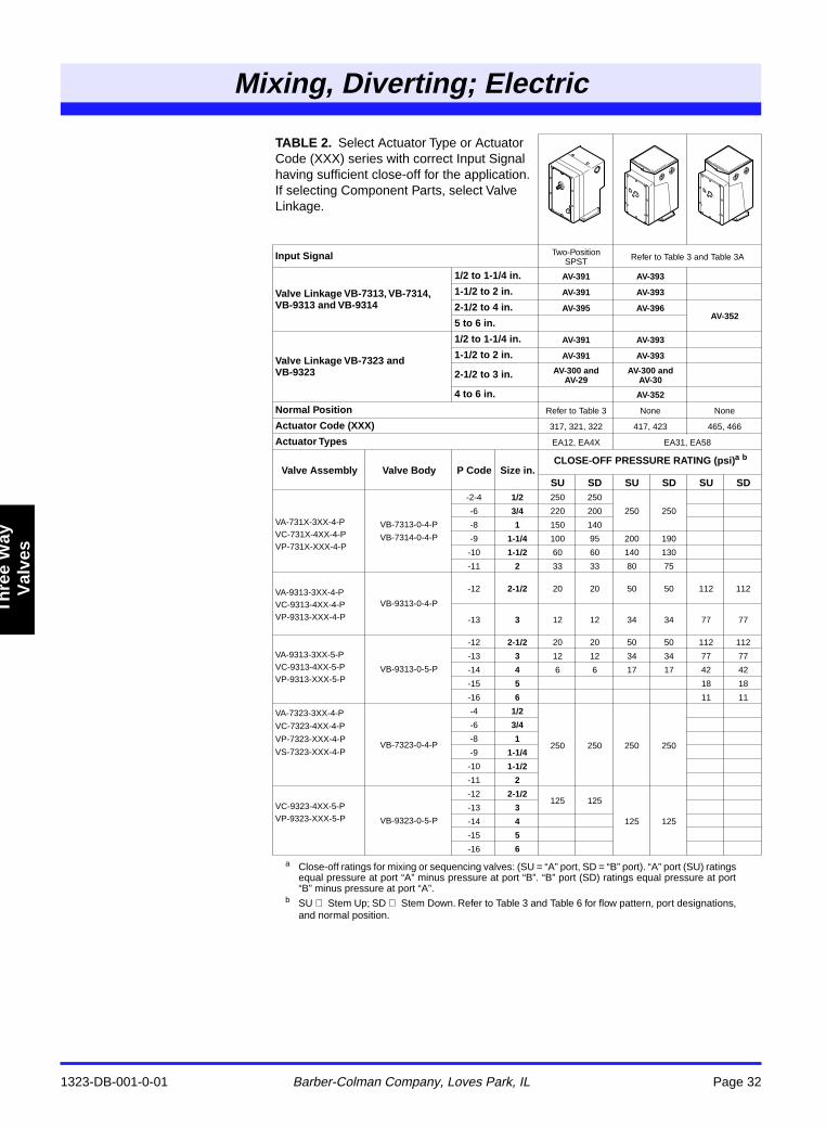
a Close-off ratings for mixing or sequencing valves: (SU = “A” port, SD = “B” port). “A” port (SU) ratingsequal pressure at port “A” minus pressure at port “B”. “B” port (SD) ratings equal pressure at port“B” minus pressure at port “A”.
b SU Stem Up; SD Stem Down. Refer to Table 3 and Table 6 for flow pattern, port designations,and normal position.
TABLE 2. Select Actuator Type or Actuator Code (XXX) series with correct Input Signal having sufficient close-off for the application. If selecting Component Parts, select Valve Linkage.
Input Signal Two-Position SPST Refer to Table 3 and Table 3A
Valve Linkage VB-7313, VB-7314, VB-9313 and VB-9314
1/2 to 1-1/4 in. AV-391 AV-393
1-1/2 to 2 in. AV-391 AV-393
2-1/2 to 4 in. AV-395 AV-396AV-352
5 to 6 in.
Valve Linkage VB-7323 and VB-9323
1/2 to 1-1/4 in. AV-391 AV-393
1-1/2 to 2 in. AV-391 AV-393
2-1/2 to 3 in. AV-300 andAV-29
AV-300 andAV-30
4 to 6 in. AV-352
Normal Position Refer to Table 3 None None
Actuator Code (XXX) 317, 321, 322 417, 423 465, 466
Actuator Types EA12, EA4X EA31, EA58
Valve Assembly Valve Body P Code Size in.CLOSE-OFF PRESSURE RATING (psi)a b
SU SD SU SD SU SD
VA-731X-3XX-4-PVC-731X-4XX-4-PVP-731X-XXX-4-P
VB-7313-0-4-P
VB-7314-0-4-P
-2-4 1/2 250 250
250 250-6 3/4 220 200
-8 1 150 140
-9 1-1/4 100 95 200 190
-10 1-1/2 60 60 140 130
-11 2 33 33 80 75
VA-9313-3XX-4-PVC-9313-4XX-4-PVP-9313-XXX-4-P
VB-9313-0-4-P
-12 2-1/2 20 20 50 50 112 112
-13 3 12 12 34 34 77 77
VA-9313-3XX-5-PVC-9313-4XX-5-PVP-9313-XXX-5-P
VB-9313-0-5-P
-12 2-1/2 20 20 50 50 112 112
-13 3 12 12 34 34 77 77
-14 4 6 6 17 17 42 42
-15 5 18 18
-16 6 11 11
VA-7323-3XX-4-P
VC-7323-4XX-4-P
VP-7323-XXX-4-P
VS-7323-XXX-4-PVB-7323-0-4-P
-4 1/2
250 250 250 250
-6 3/4
-8 1
-9 1-1/4
-10 1-1/2
-11 2
VC-9323-4XX-5-PVP-9323-XXX-5-P VB-9323-0-5-P
-12 2-1/2125 125
125 125
-13 3
-14 4
-15 5
-16 6
Mixing, Diverting; Electric
1323-DB-001-0-01 Barber-Colman Company, Loves Park, IL Page 33
Th
ree
Way
Val
ves
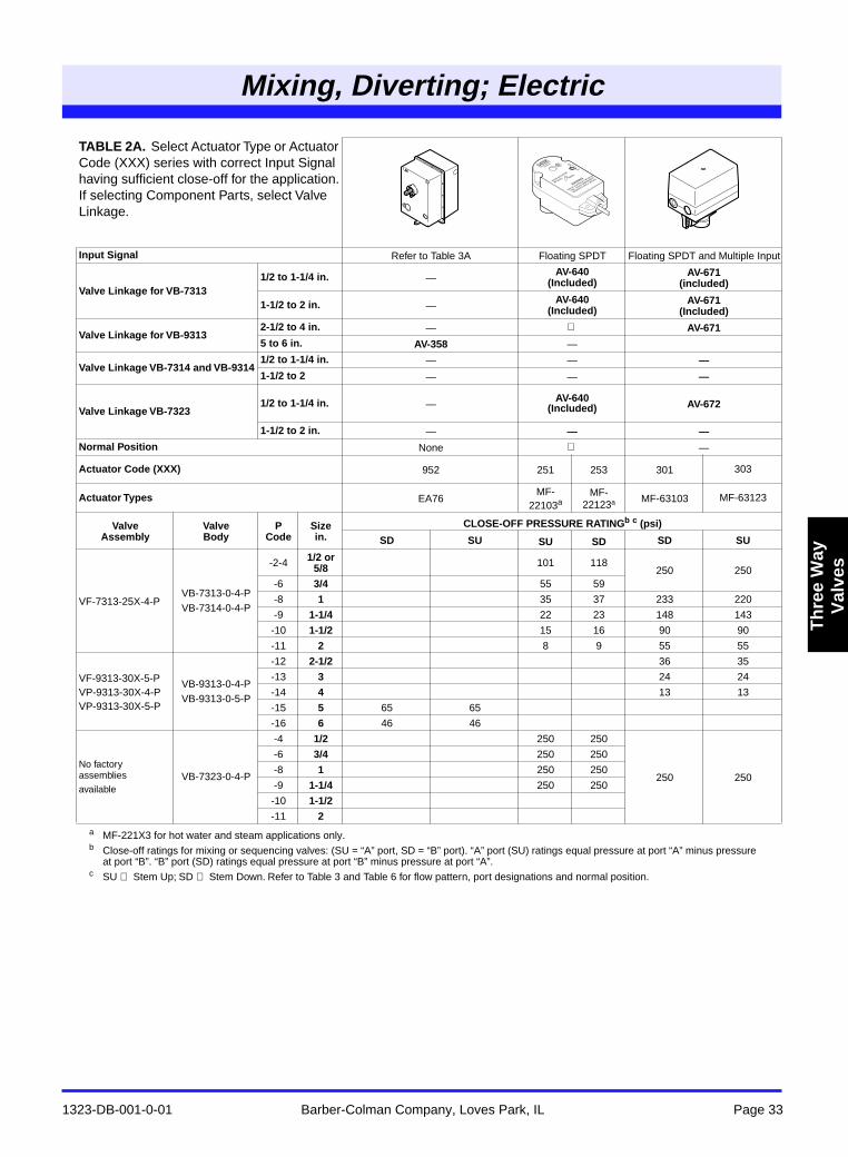
a MF-221X3 for hot water and steam applications only.b Close-off ratings for mixing or sequencing valves: (SU = “A” port, SD = “B” port). “A” port (SU) ratings equal pressure at port “A” minus pressure
at port “B”. “B” port (SD) ratings equal pressure at port “B” minus pressure at port “A”.c SU Stem Up; SD Stem Down. Refer to Table 3 and Table 6 for flow pattern, port designations and normal position.
TABLE 2A. Select Actuator Type or Actuator Code (XXX) series with correct Input Signal having sufficient close-off for the application. If selecting Component Parts, select Valve Linkage.
Input Signal Refer to Table 3A Floating SPDT Floating SPDT and Multiple Input
Valve Linkage for VB-73131/2 to 1-1/4 in. —
AV-640(Included)
AV-671(included)
1-1/2 to 2 in. —AV-640
(Included)AV-671
(Included)
Valve Linkage for VB-93132-1/2 to 4 in. — AV-6715 to 6 in. AV-358 —
Valve Linkage VB-7314 and VB-93141/2 to 1-1/4 in. — — —1-1/2 to 2 — — —
Valve Linkage VB-73231/2 to 1-1/4 in. —
AV-640(Included) AV-672
1-1/2 to 2 in. — — —Normal Position None —
Actuator Code (XXX) 952 251 253 301 303
Actuator Types EA76MF-
22103aMF-
22123a MF-63103 MF-63123
ValveAssembly
ValveBody
PCode
Sizein.
CLOSE-OFF PRESSURE RATINGb c (psi)
SD SU SU SD SD SU
VF-7313-25X-4-PVB-7313-0-4-PVB-7314-0-4-P
-2-4 1/2 or 5/8 101 118
250 250-6 3/4 55 59
-8 1 35 37 233 220
-9 1-1/4 22 23 148 143
-10 1-1/2 15 16 90 90
-11 2 8 9 55 55
VF-9313-30X-5-PVP-9313-30X-4-PVP-9313-30X-5-P
VB-9313-0-4-PVB-9313-0-5-P
-12 2-1/2 36 35
-13 3 24 24
-14 4 13 13
-15 5 65 65
-16 6 46 46
No factory assemblies
availableVB-7323-0-4-P
-4 1/2 250 250
250 250
-6 3/4 250 250
-8 1 250 250
-9 1-1/4 250 250
-10 1-1/2
-11 2
Mixing, Diverting; Electric
1323-DB-001-0-01 Barber-Colman Company, Loves Park, IL Page 34
Th
ree
Way
V
alve
s
Three Way
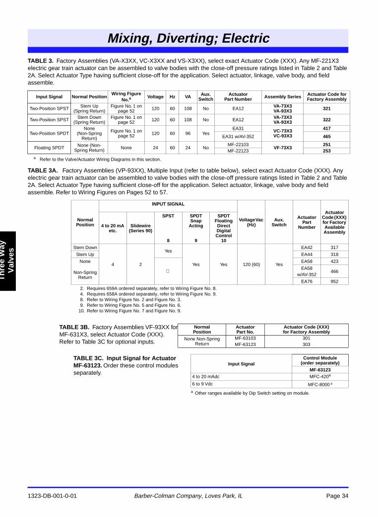
TABLE 3. Factory Assemblies (VA-X3XX, VC-X3XX and VS-X3XX), select exact Actuator Code (XXX). Any MF-221X3 electric gear train actuator can be assembled to valve bodies with the close-off pressure ratings listed in Table 2 and Table 2A. Select Actuator Type having sufficient close-off for the application. Select actuator, linkage, valve body, and field assemble.
TABLE 3A. Factory Assemblies (VP-93XX), Multiple Input (refer to table below), select exact Actuator Code (XXX). Any electric gear train actuator can be assembled to valve bodies with the close-off pressure ratings listed in Table 2 and Table 2A. Select Actuator Type having sufficient close-off for the application. Select actuator, linkage, valve body and field assemble. Refer to Wiring Figures on Pages 52 to 57.
a Refer to the Valve/Actuator Wiring Diagrams in this section.
a Other ranges available by Dip Switch setting on module.
Input Signal Normal PositionWiring Figure
No.aVoltage Hz VA Aux.
SwitchActuator
Part Number Assembly Series Actuator Code for Factory Assembly
Two-Position SPST Stem Up (Spring Return)
Figure No. 1 on page 52 120 60 108 No EA12 VA-73X3
VA-93X3 321
Two-Position SPST Stem Down (Spring Return)
Figure No. 1 on page 52 120 60 108 No EA12 VA-73X3
VA-93X3 322
Two-Position SPDTNone
(Non-Spring Return)
Figure No. 1 on page 52 120 60 96 Yes
EA31 VC-73X3VC-93X3
417
EA31 w/AV-352 465
Floating SPDT None (Non-Spring Return) None 24 60 24 No
MF-22103VF-73X3
251MF-22123 253
Normal Position
INPUT SIGNAL
Voltage Vac (Hz)
Aux. Switch
ActuatorPart
Number
Actuator Code (XXX) for Factory Available Assembly
4 to 20 mA etc.
Slidewire (Series 90)
SPST
8
SPDT Snap
Acting
9
SPDT Floating Direct Digital Control
10
Stem Down
4 2
Yes
Yes Yes 120 (60) Yes
EA42 317
Stem Up EA44 318
None
EA58 423
Non-SpringReturn
EA58 w/AV-352
466
EA76 952
2. Requires 659A ordered separately, refer to Wiring Figure No. 8.4. Requires 658A ordered separately, refer to Wiring Figure No. 9.8. Refer to Wiring Figure No. 2 and Figure No. 3.9. Refer to Wiring Figure No. 5 and Figure No. 6.
10. Refer to Wiring Figure No. 7 and Figure No. 9.
TABLE 3B. Factory Assemblies VF-93XX for MF-631X3, select Actuator Code (XXX). Refer to Table 3C for optional inputs.
NormalPosition
ActuatorPart No.
Actuator Code (XXX)for Factory Assembly
None Non-Spring Return
MF-63103MF-63123
301303
TABLE 3C. Input Signal for Actuator MF-63123. Order these control modules separately.
Input SignalControl Module
(order separately)
MF-631234 to 20 mAdc MFC-420a
6 to 9 Vdc MFC-8000 a
Mixing, Diverting; Electric
1323-DB-001-0-01 Barber-Colman Company, Loves Park, IL Page 35
Th
ree
Way
Val
ves
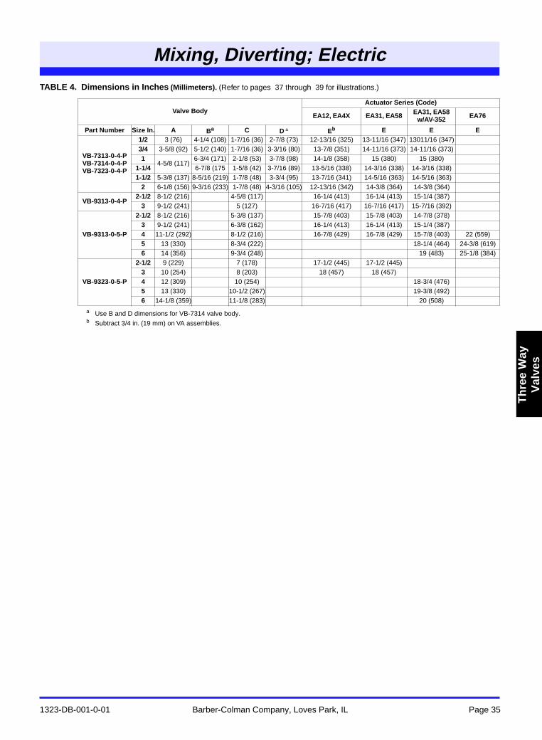
TABLE 4. Dimensions in Inches (Millimeters). (Refer to pages 37 through 39 for illustrations.)
a Use B and D dimensions for VB-7314 valve body.b Subtract 3/4 in. (19 mm) on VA assemblies.
Valve BodyActuator Series (Code)
EA12, EA4X EA31, EA58 EA31, EA58w/AV-352 EA76
Part Number Size In. A Ba C D a Eb E E E
VB-7313-0-4-PVB-7314-0-4-PVB-7323-0-4-P
1/2 3 (76) 4-1/4 (108) 1-7/16 (36) 2-7/8 (73) 12-13/16 (325) 13-11/16 (347) 13011/16 (347)3/4 3-5/8 (92) 5-1/2 (140) 1-7/16 (36) 3-3/16 (80) 13-7/8 (351) 14-11/16 (373) 14-11/16 (373)1
4-5/8 (117)6-3/4 (171) 2-1/8 (53) 3-7/8 (98) 14-1/8 (358) 15 (380) 15 (380)
1-1/4 6-7/8 (175 1-5/8 (42) 3-7/16 (89) 13-5/16 (338) 14-3/16 (338) 14-3/16 (338)1-1/2 5-3/8 (137) 8-5/16 (219) 1-7/8 (48) 3-3/4 (95) 13-7/16 (341) 14-5/16 (363) 14-5/16 (363)
2 6-1/8 (156) 9-3/16 (233) 1-7/8 (48) 4-3/16 (105) 12-13/16 (342) 14-3/8 (364) 14-3/8 (364)
VB-9313-0-4-P2-1/2 8-1/2 (216) 4-5/8 (117) 16-1/4 (413) 16-1/4 (413) 15-1/4 (387)
3 9-1/2 (241) 5 (127) 16-7/16 (417) 16-7/16 (417) 15-7/16 (392)
VB-9313-0-5-P
2-1/2 8-1/2 (216) 5-3/8 (137) 15-7/8 (403) 15-7/8 (403) 14-7/8 (378)3 9-1/2 (241) 6-3/8 (162) 16-1/4 (413) 16-1/4 (413) 15-1/4 (387)4 11-1/2 (292) 8-1/2 (216) 16-7/8 (429) 16-7/8 (429) 15-7/8 (403) 22 (559)5 13 (330) 8-3/4 (222) 18-1/4 (464) 24-3/8 (619)6 14 (356) 9-3/4 (248) 19 (483) 25-1/8 (384)
VB-9323-0-5-P
2-1/2 9 (229) 7 (178) 17-1/2 (445) 17-1/2 (445)3 10 (254) 8 (203) 18 (457) 18 (457)4 12 (309) 10 (254) 18-3/4 (476)5 13 (330) 10-1/2 (267) 19-3/8 (492)6 14-1/8 (359) 11-1/8 (283) 20 (508)
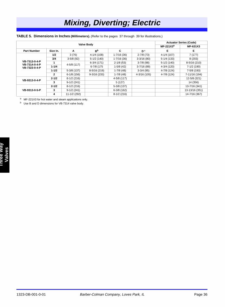
Mixing, Diverting; Electric
1323-DB-001-0-01 Barber-Colman Company, Loves Park, IL Page 36
Th
ree
Way
V
alve
s
Three Way
TABLE 5. Dimensions in Inches (Millimeters). (Refer to the pages 37 through 39 for illustrations.)
a MF-221X3 for hot water and steam applications only.b Use B and D dimensions for VB-7314 valve body.
Valve BodyActuator Series (Code)
MF-221X3a MF-631X3
Part Number Size In. A Bb C D a E E
VB-7313-0-4-PVB-7314-0-4-PVB-7323-0-4-P
1/2 3 (76) 4-1/4 (108) 1-7/16 (36) 2-7/8 (73) 4-1/4 (107) 7 (177)3/4 3-5/8 (92) 5-1/2 (140) 1-7/16 (36) 3-3/16 (80) 5-1/4 (133) 8 (203)1
4-5/8 (117)6-3/4 (171) 2-1/8 (53) 3-7/8 (98) 5-1/2 (140) 8-5/16 (210)
1-1/4 6-7/8 (175 1-5/8 (42) 3-7/16 (89) 4-3/4 (120) 7-1/2 (190)1-1/2 5-3/8 (137) 8-5/16 (219) 1-7/8 (48) 3-3/4 (95) 4-7/8 (124) 7-5/8 (193)
2 6-1/8 (156) 9-3/16 (233) 1-7/8 (48) 4-3/16 (105) 4-7/8 (124) 7-11/16 (194)
VB-9313-0-4-P2-1/2 8-1/2 (216) 4-5/8 (117) 12-5/8 (321)
3 9-1/2 (241) 5 (127) 14 (356)
VB-9313-0-5-P2-1/2 8-1/2 (216) 5-3/8 (137) 13-7/16 (341)
3 9-1/2 (241) 6-3/8 (162) 13-13/16 (351)4 11-1/2 (292) 8-1/2 (216) 14-7/16 (367)
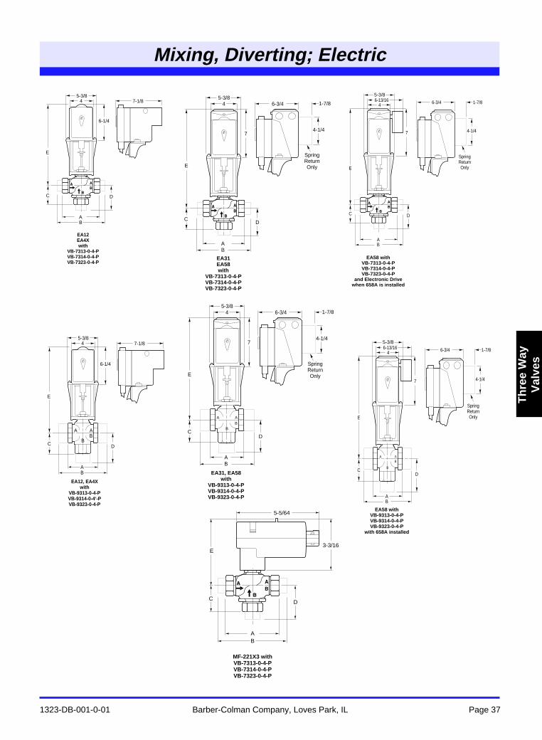
Mixing, Diverting; Electric
1323-DB-001-0-01 Barber-Colman Company, Loves Park, IL Page 37
Th
ree
Way
Val
ves
Refer to Table 4 and Table 5 for dimensional data.
6-1/4
7-1/8
E
C D
45-3/8
AB
EA12 EA4X with
VB-7313-0-4-P VB-7314-0-4-P VB-7323-0-4-P
6-1/4
7-1/8
E
C D
45-3/8
AB
A A
BB
EA12, EA4X with
VB-9313-0-4-P VB-9314-0-4‘-P VB-9323-0-4-P
7
6-3/4 1-7/8
4-1/4
E
CD
45-3/8
AB
A A
BB
Spring Return Only
EA31, EA58 with
VB-9313-0-4-P VB-9314-0-4-P VB-9323-0-4-P
5-5/64
AB
MF-221X3 with VB-7313-0-4-P VB-7314-0-4-P VB-7323-0-4-P
3-3/16E
CD
7
6-3/4 1-7/8
4-1/4
E
CD
45-3/8
AB
Spring Return Only
EA31 EA58 with
VB-7313-0-4-P VB-7314-0-4-P VB-7323-0-4-P
7
6-3/4 1-7/8
4-1/4
E
C D
4
AB
Spring Return Only
5-3/86-13/16
EA58 with VB-7313-0-4-P VB-7314-0-4-P VB-7323-0-4-P
and Electronic Drive when 658A is installed
7
6-3/4 1-7/8
4-1/4
E
CD
4
AB
A A
B
B
Spring Return Only
5-3/86-13/16
EA58 with VB-9313-0-4-P VB-9314-0-4-P VB-9323-0-4-P
with 658A installed
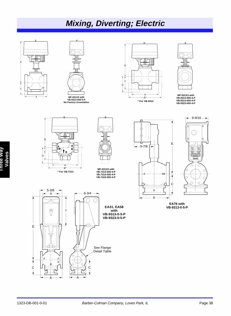
Mixing, Diverting; Electric
1323-DB-001-0-01 Barber-Colman Company, Loves Park, IL Page 38
Th
ree
Way
V
alve
s
Three Way
Refer to Table 4 and Table 5 for dimensional data.
E
C
A MF-631X3 with VB-9313-000-5-P
No Factory Assemblies
E
C
D
AB*
MF-631X3 with VB-9313-000-4-P VB-9314-000-4-P VB-9323-000-4-P
* For VB-9314
E
C
D
AB* MF-631X3 with
VB-7313-000-4-P VB-7314-000-4-P VB-7323-000-4-P
* For VB-7314
E
C
9-9/16
9-7/8
A
EA76 with VB-9313-0-5-P
A
B
AB
E
A A
C
6-3/4
A A
BB
7
45-3/8
C
EA31, EA58 with
VB-9313-0-5-P VB-9323-0-5-P
See Flange Detail Table
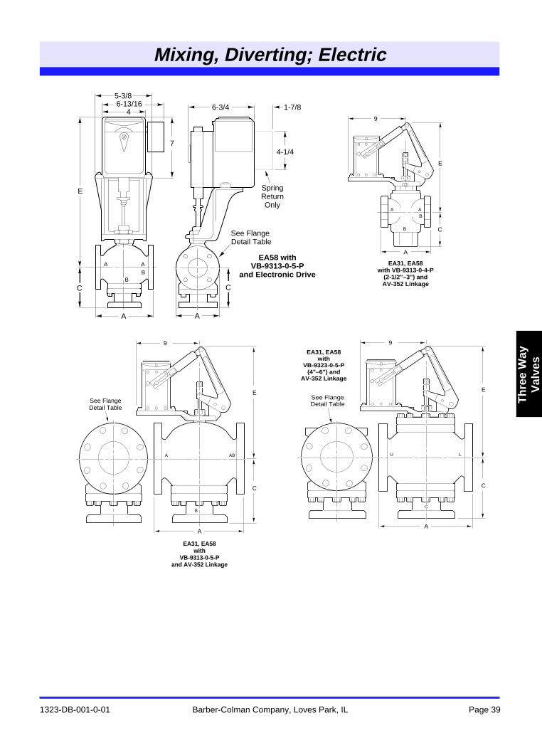
Mixing, Diverting; Electric
1323-DB-001-0-01 Barber-Colman Company, Loves Park, IL Page 39
Th
ree
Way
Val
ves
Refer to Table 4 and Table 5 for dimensional data.
E
9
U L
C
A
C
EA31, EA58 with
VB-9323-0-5-P (4"–6") and
AV-352 Linkage
See Flange Detail Table
9
E
A
C
A A
B
B
EA31, EA58 with VB-9313-0-4-P
(2-1/2"–3") and AV-352 Linkage
A AB
B
E
A
C
9
EA31, EA58 with
VB-9313-0-5-P and AV-352 Linkage
See Flange Detail Table
74-1/4
Spring Return Only
See Flange Detail Table
E
A A
C
4
5-3/8
6-3/4 1-7/8
A AB
B
C
6-13/16
EA58 with VB-9313-0-5-P
and Electronic Drive
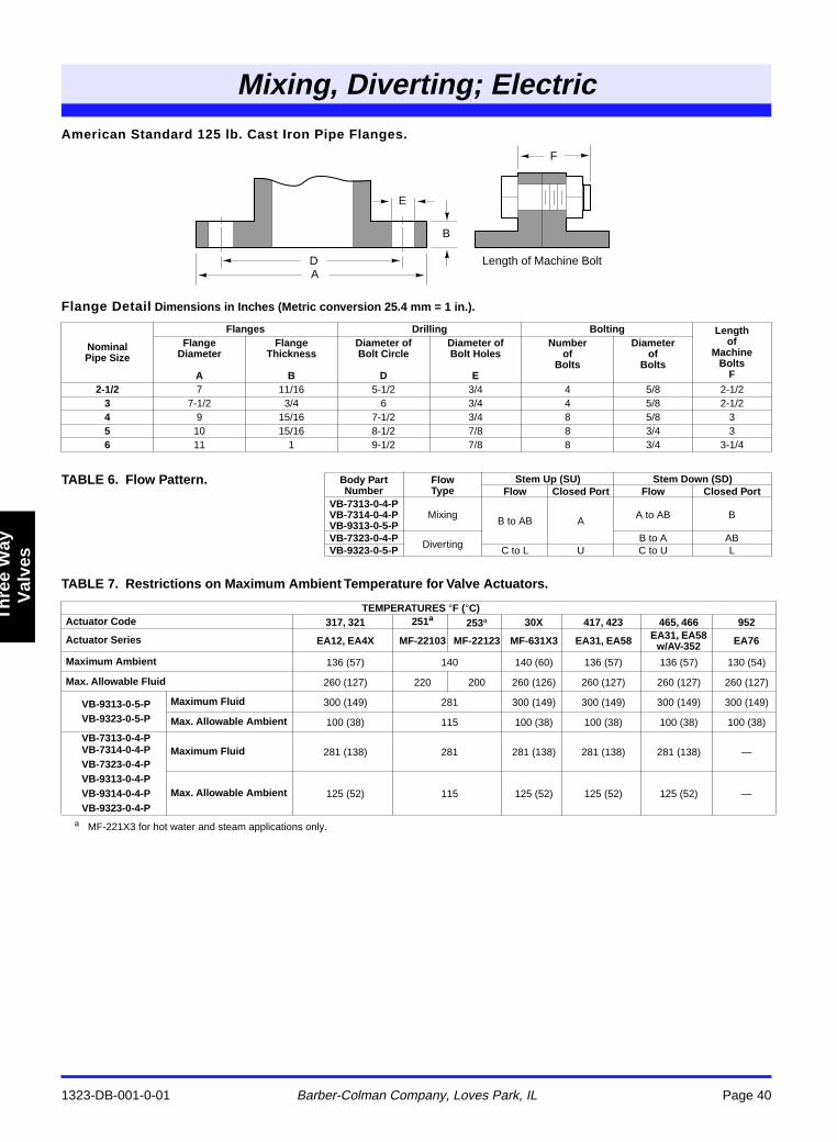
Mixing, Diverting; Electric
1323-DB-001-0-01 Barber-Colman Company, Loves Park, IL Page 40
Th
ree
Way
V
alve
s
Three Way
American Standard 125 lb. Cast Iron Pipe Flanges.
Flange Detail Dimensions in Inches (Metric conversion 25.4 mm = 1 in.).
TABLE 7. Restrictions on Maximum Ambient Temperature for Valve Actuators.
a MF-221X3 for hot water and steam applications only.
NominalPipe Size
Flanges Drilling Bolting Lengthof
MachineBolts
F
FlangeDiameter
A
FlangeThickness
B
Diameter ofBolt Circle
D
Diameter ofBolt Holes
E
Numberof
Bolts
Diameterof
Bolts
2-1/2 7 11/16 5-1/2 3/4 4 5/8 2-1/23 7-1/2 3/4 6 3/4 4 5/8 2-1/24 9 15/16 7-1/2 3/4 8 5/8 35 10 15/16 8-1/2 7/8 8 3/4 36 11 1 9-1/2 7/8 8 3/4 3-1/4
TABLE 6. Flow Pattern. Body Part Number
FlowType
Stem Up (SU) Stem Down (SD)Flow Closed Port Flow Closed Port
VB-7313-0-4-PVB-7314-0-4-PVB-9313-0-5-P
MixingB to AB A
A to AB B
VB-7323-0-4-PDiverting
B to A ABVB-9323-0-5-P C to L U C to U L
TEMPERATURES °F (°C)Actuator Code 317, 321 251a 253a 30X 417, 423 465, 466 952
Actuator Series EA12, EA4X MF-22103 MF-22123 MF-631X3 EA31, EA58 EA31, EA58w/AV-352 EA76
Maximum Ambient 136 (57) 140 140 (60) 136 (57) 136 (57) 130 (54)
Max. Allowable Fluid 260 (127) 220 200 260 (126) 260 (127) 260 (127) 260 (127)
VB-9313-0-5-PVB-9323-0-5-P
Maximum Fluid 300 (149) 281 300 (149) 300 (149) 300 (149) 300 (149)
Max. Allowable Ambient 100 (38) 115 100 (38) 100 (38) 100 (38) 100 (38)
VB-7313-0-4-PVB-7314-0-4-PVB-7323-0-4-PVB-9313-0-4-PVB-9314-0-4-PVB-9323-0-4-P
Maximum Fluid 281 (138) 281 281 (138) 281 (138) 281 (138) —
Max. Allowable Ambient 125 (52) 115 125 (52) 125 (52) 125 (52) —
D Length of Machine BoltA
E
B
F
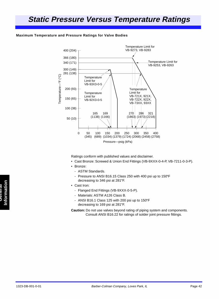
1323-DB-001-0-01 Barber-Colman Company, Loves Park, IL Page 42
Static Pressure Versus Temperature Ratings
Gen
eral
Info
rmat
ion
Maximum Temperature and Pressure Ratings for Valve Bodies
Ratings conform with published values and disclaimer.• Cast Bronze: Screwed & Union End Fittings (VB-9XXX-0-4-P, VB-7211-0-3-P).• Bronze:
- ASTM Standards.- Pressure to ANSI B16.15 Class 250 with 400 psi up to 150°F
decreasing to 346 psi at 281°F.• Cast Iron:
- Flanged End Fittings (VB-9XXX-0-5-P).- Materials: ASTM A126 Class B.- ANSI B16.1 Class 125 with 200 psi up to 150°F
decreasing to 169 psi at 281°F.
Caution: Do not use valves beyond rating of piping system and components.Consult ANSI B16.22 for ratings of solder joint pressure fittings.
Static Pressure VersusTempeature Ratings
Pressure—psig (kPa)
100 (689)
50 (345)
0 150 (1034)
200 (1379)
250 (1724)
300 (2068)
350 (2458)
400 (2758)
50 (10)
100 (38)
150 (65)
200 (93)
281 (138)300 (149)
340 (171)
366 (180)
400 (204)
Tem
pera
ture
—°F
(°C
)
Temperature Limit for VB-9273, VB-9283
Temperature Limit for VB-721X, 921X, VB-722X, 922X, VB-73XX, 93XX
Temperature Limit for VB-93X3-0-5
Temperature Limit for VB-92X3-0-5
165 (1138)
169 (1166)
270 (1863)
286 (1973)
321 (2218)
Temperature Limit for VB-9253, VB-9263
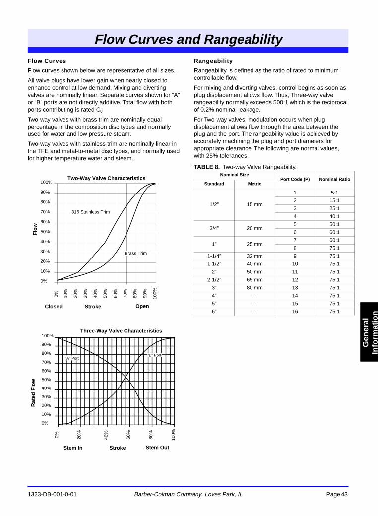
1323-DB-001-0-01 Barber-Colman Company, Loves Park, IL Page 43
Flow Curves and Rangeability
Gen
eral
Info
rmat
ion
Flow Curves
Flow curves shown below are representative of all sizes.
All valve plugs have lower gain when nearly closed to enhance control at low demand. Mixing and diverting valves are nominally linear. Separate curves shown for “A” or “B” ports are not directly additive. Total flow with both ports contributing is rated Cv.
Two-way valves with brass trim are nominally equal percentage in the composition disc types and normally used for water and low pressure steam.
Two-way valves with stainless trim are nominally linear in the TFE and metal-to-metal disc types, and normally used for higher temperature water and steam.
Rangeability
Rangeability is defined as the ratio of rated to minimum controllable flow.
For mixing and diverting valves, control begins as soon as plug displacement allows flow. Thus, Three-way valve rangeability normally exceeds 500:1 which is the reciprocal of 0.2% nominal leakage.
For Two-way valves, modulation occurs when plug displacement allows flow through the area between the plug and the port. The rangeability value is achieved by accurately machining the plug and port diameters for appropriate clearance. The following are normal values, with 25% tolerances.
TABLE 8. Two-way Valve Rangeability.
Two-Way Valve Characteristics
Flo
w
Stroke
0%
100%
90%
80%
70%
60%
50%
40%
30%
20%
10%
0% 100%
90%
80%
70%
60%
50%
40%
30%
20%
10%
316 Stainless Trim
Brass Trim
Closed Open
Rat
ed F
low
Stroke
Three-Way Valve Characteristics
Stem In Stem Out
0%
100%
90%
80%
70%
60%
50%
40%
30%
20%
10%
0% 80%
60%
40%
20%
100%
"A" Port"B" Port
Nominal SizePort Code (P) Nominal Ratio
Standard Metric
1/2” 15 mm
1 5:1
2 15:1
3 25:1
4 40:1
3/4” 20 mm5 50:1
6 60:1
1” 25 mm7 60:1
8 75:1
1-1/4” 32 mm 9 75:1
1-1/2” 40 mm 10 75:1
2” 50 mm 11 75:1
2-1/2” 65 mm 12 75:1
3” 80 mm 13 75:1
4” — 14 75:1
5” — 15 75:1
6” — 16 75:1
Flow Curvesand Rangeility
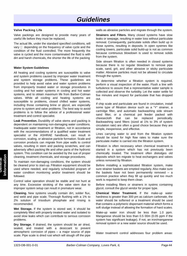
1323-DB-001-0-01 Barber-Colman Company, Loves Park, IL Page 44
Guidelines
Gen
eral
Info
rmat
ion
Valve Packing Life
Valve packings are designed to provide many years ofuseful life before they must be replaced.
The actual life, under the standard specified conditions, willvary depending on the frequency of valve cycle and thecondition of the fluid controlled. The more frequently thevalve is cycled and the more contaminated the fluid is withdirt and harsh chemicals, the shorter the life of the packing
Water System Guidelines
All heating and cooling systems are susceptible to valveand system problems caused by improper water treatmentand system storage problems. These guidelines areprovided to help avoid valve and water system problemsfrom improperly treated water or storage procedures incooling and hot water systems in cooling and hot watersystems, and to obtain maximum life from Barber-Colmanvalves. While all cooling and heating systems aresusceptible to problems, closed chilled water systems,including those containing brine or glycol, are especiallyprone to system and valve problems. The best way to avoidproblems is to follow the advice of a professional watertreatment and control specialist.
Leak Prevention. Durability of valve stems and packing isdependent on maintaining non-damaging water conditions.Inadequate water treatment or filtration, not in accordancewith the recommendations of a qualified water treatmentspecialist or the ASHRAE handbook, can result incorrosion, scaling, or abrasive particle formation. Scale andcorrosion products can migrate from pipe walls to controlvalves, resulting in stem and packing scratches, and canadversely affect packing life and other parts of the hydronicsystem. This condition can be avoided by the sue of propercleaning, treatment chemicals, and storage procedures.
To maintain non-damaging conditions, the system shouldbe cleaned prior to start-up. Filtration equipment should beused where needed, and regularly scheduled program ofwater condition monitoring and/or treatment should befollowed.
Control valve operation should be stable and not hunt atany time. Excessive stroking of the valve stem due toimproper system setup can result in premature wear.
Cleaning. New systems usually contain dirt, solder flux,and weld and pipe scale. Thorough flushing with a 1% to2% solution of trisodium phosphate and rinsing isrecommended.
Wet Storage. If the system is stored wet, it should becompletely filled with properly treated water and isolated toavoid slow leaks which can contribute to serious corrosionproblems.
Dry Storage. If drained, the system should be air dried,sealed, and treated with a desiccant to preventatmospheric corrosion of pipes – a major source of pipescale. Pipe scale is dried rust which will slough off the pipe
walls as abrasive particles and migrate through the system.
Strainers and Filters. Many closed systems have slowleaks or seepage, resulting in water loss without particulateremoval. Consequently, particulate solids often build up inthose systms, resulting in deposits. In open systmes likecooling towers, particulate solid build-up is not as commonbecause continuous blowdown is used to remove solidsfrom the system.
Side stream filtration is often needed in closed systemsbecause there is no regular blowdown to remove pipescale, sand, grit, and other abrasive or sticky particulatematter. Abrasive particles must not be allowed to circulatethrough the system.
To determine whether a filtration system is required,perform a visual inspection of the water. Flush a line withturbulence to assure that a representative water sample iscollected and observe the turbidity. Let the water settle forfive minutes and inspect for particulate that has droppedout.
If chip scale and particulate are found in circulation, installsome type of filtration device such as a “Y” strainer, acartridge filter, and automatic backwashing side streamsand filter, or a chemical pot feeder packed withcheesecloth that can be replaced periodically.Backwashing sand filters (sized at 1% to 3% of systemcirculation rate) are often a good choice because they aresimple, inexpensive, and effective.
Lines carrying water to and from the filtration systemshould be sized for high flow rates to make sure theparticulate matter is carried into the filtration system.
Filtration is often necessary when chemical treatment isstarted in a system which has not previously beenchemically treated. The treatment often dislodges olddeposits which ten migrate to heat exchangers and valvesunless removed by filtration.
Before installing a sophisticated filtration system, makesure strainer baskets are emptied regularly. Also make surethe baskets have not been permanently removed – acommon practice when they fill up quickly and too muchwork is required to keep them clean.
Before installing filters or strainers in systms containingglycol, consult the glycol vendor for proper type.
Chemical Water Treatment. If the make-up waterhardness is greater than 300 pm as calcium carbonate, thewater should be softened or a treatment should be usedthat contains a polymeric dispersant material which forms asoft sludge instead of allowing the formation of hard scales.
Make-up water iron should be less than 1.0 ppm.Manganese should be less than 0.5 00m (0.05 ppm if thesystem has significant leakage). If not, an iron/manganeseremoval system or a new water source should be used.
Water treatment control addresses four problem areas:
Guidelins
1323-DB-001-0-01 Barber-Colman Company, Loves Park, IL Page 45
Guidelines
Gen
eral
Info
rmat
ion
corrosion, scale, deposition, and bacteria. For control, anitrite or molybdate based program is typically used inconjunction with testing and monitoring.
The corrosion control program most commonly used is 600to 1220 ppm sodium nitrite or 100 to 300 ppm molybdate,at a pH of 9.5 to 10.5. Include a copper corrosion inhibitorsuch as Tolytriazol (TTA) or Benzotriazole (BZT) sinceuncontrolled copper corrosion can lead to corrosion ofsteel.
Note – The addition of glycol, especially automotiveantifreeze, does not assure corrosion protection. Refer tothe manufacturer’s literature for specific requirements,including concentrations and materials of construction.
Control of bacteria is important because bacteria can breakdown the nitrites. The level of bacteria should be kept atless than 10,000 CFUs (colony forming units) per ml ofwater. Follow your supplier’s instructions for bacterialcontrol.
Operate your chemical treatment program within theguidelines set by your water treatment supplier. Monitorresults monthly, switching to weekly if problem resolution isnecessary.
Control Loop Operation. Valves should not be oversized.Set the control system operating parameters so thathunting does not occur, even at light load conditions suchas fall, spring, and morning operation. Valves which cycleoften or continuously require a preventive maintenanceprogram to replace worn parts.
Valve Sizing Information for Water
1323-DB-001-0-01 Barber-Colman Company, Loves Park, IL Page 46
Gen
eral
In
form
atio
n
GENERAL INFORMATION REQUIRED
1. Fluid controlled:• Chilled water, hot water, or steam.
2. Temperature limitations:• Fluid, maximum, and minimum.• Ambient for actuator.
3. Pressure:• Static.• Close-off Fully closed.• Differential Pressure drop across the valve in the
fully open position.4. End fitting:
• Union end.• Globe screwed.• Flared.• Flanged.• Flangeless.
5. For return to a known position (i.e., normally open or normally closed): Specify 200 or 300 Series spring return actuator.
6. Dimensional data.7. Cv (flow coefficient) requirement is calculated from flow
rate and differential pressure. Refer to formulas and tables.
For additional sizing and selection background information, refer to:
• CA-28 Control Valve Sizing, F-13755.• CA-27 Three-Way Valves, F-12348.• CA-15 Control of High Temperature Water Systems,
F-7638.• CA-13 Fundamentals of Hot Water Pump
Installation, F-7767.
RECOMMENDED PRESSURE DROPS FOR WATER
Refer to specific valve data in this catalog for maximum allowable pressure drops and close-off ratings.
A. Two-Position Valves
Two-position valves are normally selected “line size” to keep pressure drop at a minimum. If desirable to reduce valve below line size, then 10% of “available pressure” normally used to select valve.
B. Proportional Two-Way Valves
Usually selected to take a pressure drop equal to at least 50% of the “available pressure” (i.e., the pump pressure differential available between supply and return mains with design flow at the valve location). As “available pressure” is often difficult to calculate, the normal procedure is to select the valve using a pressure drop at least equal to the drop in the coil or other load being controlled (except where small booster pumps are used), but never less than 5 psi (34 kPa).
When design temperature drop is less than 60°F (33°C) for
conventional heating systems, higher pressure drops across the valve are needed for good control results. Refer to the following table.
C. Proportional Three-Way Valves
Recommended Pressure Drop Bypass Application: 50% of “available pressure”, or equal to pressure drop through the load at full flow.
Three-way valves in the return used to control heat output by throttling water flow to the load (bypass applications) are controlling output in the same manner as throttling two-way valves, and must be selected using the same high pressure drops if good control results are to be obtained.
Recommended Pressure Drop Constant Flow Applications: 20% of “available pressure”, or equal to 1/4 of the pressure drop through the load at full flow.
Three-way valves used with individual pumps to control heat output by varying water temperature to the load (constant flow applications) are controlling output by mixing two water sources at different temperatures, and do not require high pressure drops for good control results.
In most cases the required Cv falls between two valve sizes. If the pressure drop of the smaller is acceptable for the application, select the smaller valve.
CAVITATION LIMITATIONS ON VALVE PRESSURE DROP
A valve selected with too high a pressure drop can cause erosion of discs and/or wire drawing of the seat. In addition, cavitation can cause noise, damage to the valve trim (and possibly the body) and choke the flow through the valve.
Do not exceed the maximum differential pressure (pressure drop) for the valve selected.
The following formula can be used on higher temperature water systems, where cavitation could be a problem, to estimate the maximum allowable pressure drop across the valve: Pm = 0.5 (P1 - Pv)
Pm = Maximum allowable pressure drop
P1 = Absolute inlet pressure (psia)
Pv = Absolute vapor pressure (refer to Vapor Pressure of Water Table or Steam Table)
ValveSizingInformtion fWater
Conventional Heating Systems
Design Temp. Drop °F (°C)
Recom. Pressure Dropa (% of Available Pressure)
Multiplier on Load Drop
60 (33) or more 50% 1 x load drop
40 (22) 66% 2 x load drop
20 (11) 75% 3 x load drop
a Recommended minimum pressure drop 5 psi (34 kPa).
Secondary Circuits with Small Booster Pumps
50% of Available Pressure Difference (Equal to drop through load, or 50% of booster pump head)
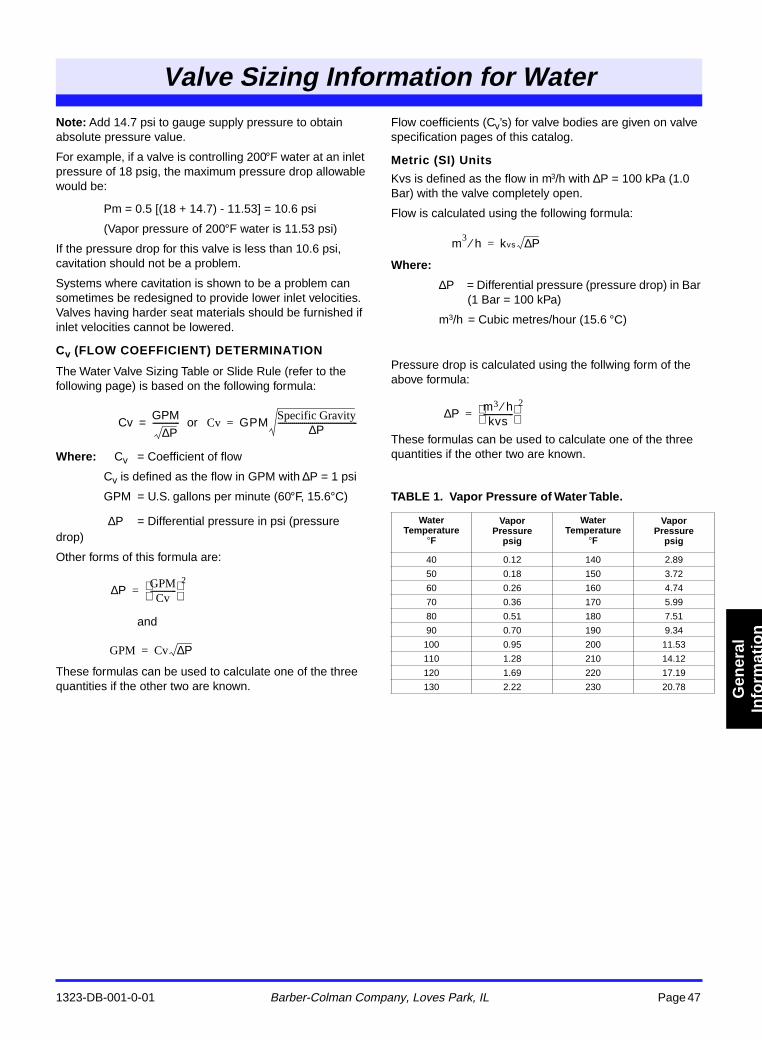
Valve Sizing Information for Water
1323-DB-001-0-01 Barber-Colman Company, Loves Park, IL Page 47
Gen
eral
In
form
atio
n
Note: Add 14.7 psi to gauge supply pressure to obtain absolute pressure value.
For example, if a valve is controlling 200°F water at an inlet pressure of 18 psig, the maximum pressure drop allowable would be:
Pm = 0.5 [(18 + 14.7) - 11.53] = 10.6 psi
(Vapor pressure of 200°F water is 11.53 psi)
If the pressure drop for this valve is less than 10.6 psi, cavitation should not be a problem.
Systems where cavitation is shown to be a problem can sometimes be redesigned to provide lower inlet velocities. Valves having harder seat materials should be furnished if inlet velocities cannot be lowered.
Cv (FLOW COEFFICIENT) DETERMINATION
The Water Valve Sizing Table or Slide Rule (refer to the following page) is based on the following formula:
or
Where: Cv = Coefficient of flow
Cv is defined as the flow in GPM with ∆P = 1 psi
GPM = U.S. gallons per minute (60°F, 15.6°C)
= Differential pressure in psi (pressure drop)
Other forms of this formula are:
and
These formulas can be used to calculate one of the three quantities if the other two are known.
Flow coefficients (Cv’s) for valve bodies are given on valve specification pages of this catalog.
Metric (SI) Units
Kvs is defined as the flow in m3/h with ∆P = 100 kPa (1.0 Bar) with the valve completely open.
Flow is calculated using the following formula:
Where:
∆P = Differential pressure (pressure drop) in Bar (1 Bar = 100 kPa)
m3/h = Cubic metres/hour (15.6 °C)
Pressure drop is calculated using the follwing form of the above formula:
These formulas can be used to calculate one of the three quantities if the other two are known.
TABLE 1. Vapor Pressure of Water Table.
CvGPM
P∆-------------= Cv GPM
Specific Gravity P
∆
---------------------------------------
=
P∆
P∆ GPMCv
------------- 2
=
GPM Cv P∆=
WaterTemperature
°
F
Vapor Pressure
psig
WaterTemperature
°
F
VaporPressure
psig
40 0.12 140 2.89
50 0.18 150 3.72
60 0.26 160 4.74
70 0.36 170 5.99
80 0.51 180 7.51
90 0.70 190 9.34
100 0.95 200 11.53
110 1.28 210 14.12
120 1.69 220 17.19
130 2.22 230 20.78
m3 h⁄ kvs P∆=
P∆ m3 h⁄kvs
---------------
2
=
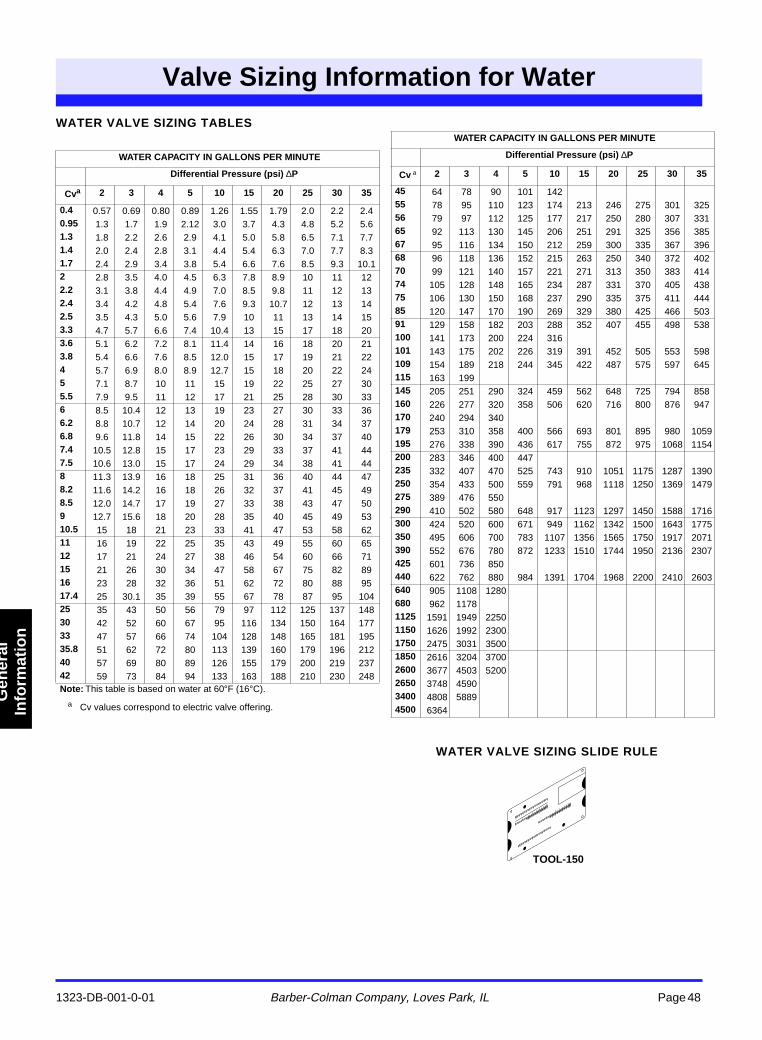
Valve Sizing Information for Water
1323-DB-001-0-01
Barber-Colman Company, Loves Park, IL
Page 48
Gen
eral
In
form
atio
n
WATER VALVE SIZING TABLES
a
Cv values correspond to electric valve offering.
WATER VALVE SIZING SLIDE RULE
WATER CAPACITY IN GALLONS PER MINUTE
Differential Pressure (psi)
∆
P
Cv
a
2 3 4 5 10 15 20 25 30 35
0.4
0.57 0.69 0.80 0.89 1.26 1.55 1.79 2.0 2.2 2.4
0.95
1.3 1.7 1.9 2.12 3.0 3.7 4.3 4.8 5.2 5.6
1.3
1.8 2.2 2.6 2.9 4.1 5.0 5.8 6.5 7.1 7.7
1.4
2.0 2.4 2.8 3.1 4.4 5.4 6.3 7.0 7.7 8.3
1.7
2.4 2.9 3.4 3.8 5.4 6.6 7.6 8.5 9.3 10.1
2
2.8 3.5 4.0 4.5 6.3 7.8 8.9 10 11 12
2.2
3.1 3.8 4.4 4.9 7.0 8.5 9.8 11 12 13
2.4
3.4 4.2 4.8 5.4 7.6 9.3 10.7 12 13 14
2.5
3.5 4.3 5.0 5.6 7.9 10 11 13 14 15
3.3
4.7 5.7 6.6 7.4 10.4 13 15 17 18 20
3.6
5.1 6.2 7.2 8.1 11.4 14 16 18 20 21
3.8
5.4 6.6 7.6 8.5 12.0 15 17 19 21 22
4
5.7 6.9 8.0 8.9 12.7 15 18 20 22 24
5
7.1 8.7 10 11 15 19 22 25 27 30
5.5
7.9 9.5 11 12 17 21 25 28 30 33
6
8.5 10.4 12 13 19 23 27 30 33 36
6.2
8.8 10.7 12 14 20 24 28 31 34 37
6.8
9.6 11.8 14 15 22 26 30 34 37 40
7.4
10.5 12.8 15 17 23 29 33 37 41 44
7.5
10.6 13.0 15 17 24 29 34 38 41 44
8
11.3 13.9 16 18 25 31 36 40 44 47
8.2
11.6 14.2 16 18 26 32 37 41 45 49
8.5
12.0 14.7 17 19 27 33 38 43 47 50
9
12.7 15.6 18 20 28 35 40 45 49 53
10.5
15 18 21 23 33 41 47 53 58 62
11
16 19 22 25 35 43 49 55 60 65
12
17 21 24 27 38 46 54 60 66 71
15
21 26 30 34 47 58 67 75 82 89
16
23 28 32 36 51 62 72 80 88 95
17.4
25 30.1 35 39 55 67 78 87 95 104
25
35 43 50 56 79 97 112 125 137 148
30
42 52 60 67 95 116 134 150 164 177
33
47 57 66 74 104 128 148 165 181 195
35.8
51 62 72 80 113 139 160 179 196 212
40
57 69 80 89 126 155 179 200 219 237
42
59 73 84 94 133 163 188 210 230 248
Note:
This table is based on water at 60
°
F (16
°
C).
WATER CAPACITY IN GALLONS PER MINUTE
Differential Pressure (psi)
∆
P
Cv
a
2 3 4 5 10 15 20 25 30 35
45
64 78 90 101 142
55
78 95 110 123 174 213 246 275 301 325
56
79 97 112 125 177 217 250 280 307 331
65
92 113 130 145 206 251 291 325 356 385
67
95 116 134 150 212 259 300 335 367 396
68
96 118 136 152 215 263 250 340 372 402
70
99 121 140 157 221 271 313 350 383 414
74
105 128 148 165 234 287 331 370 405 438
75
106 130 150 168 237 290 335 375 411 444
85
120 147 170 190 269 329 380 425 466 503
91
129 158 182 203 288 352 407 455 498 538
100
141 173 200 224 316
101 143 175 202 226 319 391 452 505 553 598109 154 189 218 244 345 422 487 575 597 645115 163 199145 205 251 290 324 459 562 648 725 794 858160 226 277 320 358 506 620 716 800 876 947170 240 294 340179 253 310 358 400 566 693 801 895 980 1059195 276 338 390 436 617 755 872 975 1068 1154200 283 346 400 447235 332 407 470 525 743 910 1051 1175 1287 1390250 354 433 500 559 791 968 1118 1250 1369 1479275 389 476 550290 410 502 580 648 917 1123 1297 1450 1588 1716300 424 520 600 671 949 1162 1342 1500 1643 1775350 495 606 700 783 1107 1356 1565 1750 1917 2071390 552 676 780 872 1233 1510 1744 1950 2136 2307425 601 736 850440 622 762 880 984 1391 1704 1968 2200 2410 2603640 905 1108 1280680 962 11781125 1591 1949 22501150 1626 1992 23001750 2475 3031 35001850 2616 3204 37002600 3677 4503 52002650 3748 45903400 4808 58894500 6364
TOOL-150
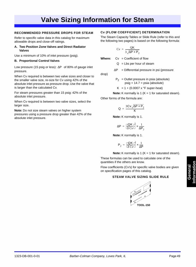
Valve Sizing Information for Steam
1323-DB-001-0-01 Barber-Colman Company, Loves Park, IL Page 49
Gen
eral
In
form
atio
n
RECOMMENDED PRESSURE DROPS FOR STEAM
Refer to specific valve data in this catalog for maximum allowable drops and close-off ratings.
A. Two Position Zone Valves and Direct Radiator Valves
Use a minimum of 10% of inlet pressure (psig).
B. Proportional Control Valves
Low pressure (15 psig or less): of 80% of gauge inlet pressure.
When Cv required is between two valve sizes and closer to the smaller valve size, re-size for Cv using 42% of the absolute inlet pressure as pressure drop. Use the valve that is larger than the calculated Cv.
For steam pressures greater than 15 psig: 42% of the absolute inlet pressure.
When Cv required is between two valve sizes, select the larger size.
Note: Do not size steam valves on higher system pressures using a pressure drop greater than 42% of the absolute inlet pressure.
Cv (FLOW COEFFICIENT) DETERMINATION
The Steam Capacity Tables or Slide Rule (refer to this and the following two pages) is based on the following formula:
Where: Cv = Coefficient of flow
Q = Lbs per hour of steam
= Differential pressure in psi (pressure drop)
P2 = Outlet pressure in psia (absolute)psig + 14.7 = psia (absolute)
K = 1 + (0.0007 x °F super-heat)
Note: K normally is 1 (K = 1 for saturated steam).
Other forms of the formula are:
Note: K normally is 1.
Note: K normally is 1.
Note: K normally is 1 (K = 1 for saturated steam).
These formulas can be used to calculate one of the quantities if the others are know.
Flow coefficients (Cv’s) for specific valve bodies are given on specification pages of this catalog.
STEAM VALVE SIZING SLIDE RULE
Valve Sizing Information for Steam
P∆
Cv QK
3 P P2×∆----------------------------=
P∆
Q3Cv P P2×∆
K------------------------------------=
P∆ QK3 Cv -----------
2
1
P 2 ∆ ---------- × =
P2QK3 Cv -----------
2
1
P ∆ -------
×
=
TOOL-150
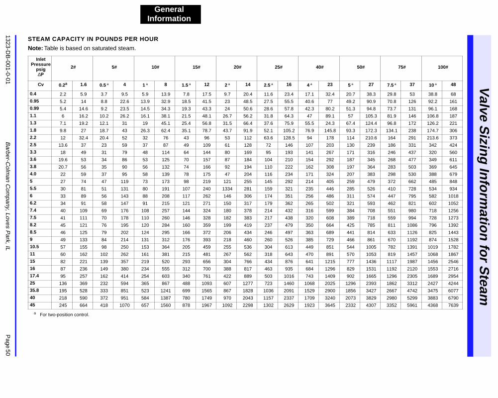
1323-DB
-001-0-01
Barber-C
olman C
ompany, Loves P
ark, IL
Page 50
Valve S
izing
Info
rmatio
n fo
r Steam
GeneralInformation
STEAM CAPACITY IN POUNDS PER HOUR
Note:
Table is based on saturated steam.
a
For two-position control.
Inlet Pressure
psig
∆
P
2# 5# 10# 15# 20# 25# 40# 50# 75# 100#
Cv 0.2
a
1.6 0.5
a
4 1
a
8 1.5
a
12 2
a
14 2.5
a
16 4
a
23 5
a
27 7.5
a
37 10
a
48
0.4
2.2 5.9 3.7 9.5 5.9 13.9 7.8 17.5 9.7 20.4 11.6 23.4 17.1 32.4 20.7 38.3 29.8 53 38.8 68
0.95
5.2 14 8.8 22.6 13.9 32.9 18.5 41.5 23 48.5 27.5 55.5 40.6 77 49.2 90.9 70.8 126 92.2 161
0.99
5.4 14.6 9.2 23.5 14.5 34.3 19.3 43.3 24 50.6 28.6 57.8 42.3 80.2 51.3 94.8 73.7 131 96.1 168
1.1
6 16.2 10.2 26.2 16.1 38.1 21.5 48.1 26.7 56.2 31.8 64.3 47 89.1 57 105.3 81.9 146 106.8 187
1.3
7.1 19.2 12.1 31 19 45.1 25.4 56.8 31.5 66.4 37.6 75.9 55.5 24.3 67.4 124.4 96.8 172 126.2 221
1.8
9.8 27 18.7 43 26.3 62.4 35.1 78.7 43.7 91.9 52.1 105.2 76.9 145.8 93.3 172.3 134.1 238 174.7 306
2.2
12 32.4 20.4 52 32 76 43 96 53 112 63.6 128.5 94 178 114 210.6 164 291 213.6 373
2.5
13.6 37 23 59 37 87 49 109 61 128 72 146 107 203 130 239 186 331 342 424
3.3
18 49 31 79 48 114 64 144 80 169 95 193 141 267 171 316 246 437 320 560
3.6
19.6 53 34 86 53 125 70 157 87 184 104 210 154 292 187 345 268 477 349 611
3.8
20.7 56 35 90 56 132 74 166 92 194 110 222 162 308 197 364 283 503 369 645
4.0
22 59 37 95 58 139 78 175 47 204 116 234 171 324 207 383 298 530 388 679
5
27 74 47 119 73 173 98 219 121 255 145 292 214 405 259 479 372 662 485 848
5.5
30 81 51 131 80 191 107 240 1334 281 159 321 235 446 285 526 410 728 534 934
6
33 89 56 143 88 208 117 262 146 306 174 351 256 486 311 574 447 795 582 1018
6.2
34 91 58 147 91 215 121 271 150 317 179 362 265 502 321 593 462 821 602 1052
7.4
40 109 69 176 108 257 144 324 180 378 214 432 316 599 384 708 551 980 718 1256
7.5
41 111 70 178 110 260 146 328 182 383 217 438 320 608 389 718 559 994 728 1273
8.2
45 121 76 195 120 284 160 359 199 419 237 479 350 664 425 785 811 1086 796 1392
8.5
46 125 79 202 124 295 166 372 206 434 246 497 363 689 441 814 633 1126 825 1443
9
49 133 84 214 131 312 176 393 218 460 260 526 385 729 466 861 670 1192 874 1528
10.5
57 155 98 250 153 364 205 459 255 536 304 613 449 851 544 1005 782 1391 1019 1782
11
60 162 102 262 161 381 215 481 267 562 318 643 470 891 570 1053 819 1457 1068 1867
15
82 221 139 357 219 520 293 656 304 766 434 876 641 1215 777 1436 1117 1987 1456 2546
16
87 236 149 380 234 555 312 700 388 817 463 935 684 1296 829 1531 1192 2120 1553 2716
17.4
95 257 162 414 254 603 340 761 422 889 503 1016 743 1409 902 1665 1296 2305 1689 2954
25
136 369 232 594 365 867 488 1093 607 1277 723 1460 1068 2025 1296 2393 1862 3312 2427 4244
35.8
195 528 333 851 523 1241 699 1565 867 1828 1036 2091 1529 2900 1856 3427 2667 4742 3475 6077
40 218 590 372 951 584 1387 780 1749 970 2043 1157 2337 1709 3240 2073 3829 2980 5299 3883 6790
45 245 664 418 1070 657 1560 878 1967 1092 2298 1302 2629 1923 3645 2332 4307 3352 5961 4368 7639
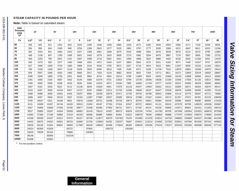
1323-DB
-001-0-01B
arber-Colm
an Com
pany, Loves Park, IL
Page 51
Valve S
izing
Info
rmatio
n fo
r Steam
General Information
STEAM CAPACITY IN POUNDS PER HOUR
Note: Table is based on saturated steam.
a For two-position control.
Inlet Pressure
psig∆P
2# 5# 10# 15# 20# 25# 40# 50# 75# 100#
Cv 0.2a 1.6 0.5 a 4 1 a 8 1.5 a 12 2 a 14 2.5 a 16 4 a 23 5 a 27 7.5 a 37 10 a 48
56 305 826 521 1331 818 1942 1093 2448 1359 2860 1620 3271 2392 4536 2903 5360 4171 7418 5436 9506
65 354 958 604 1545 949 2254 1268 2842 1577 3320 1881 3797 2777 5265 3369 6221 4842 8611 6310 11034
70 381 1032 651 1664 1022 2427 1366 3061 1698 3575 2025 4089 2991 5670 3628 6670 5214 9273 6795 11882
75 409 1106 697 1783 1095 2601 1463 3279 1820 3830 2170 4381 3204 6075 3887 7179 5587 9935 7280 12731
85 463 1253 790 2021 1241 2947 1658 3716 2062 4341 2459 4966 3631 6885 4406 8136 6332 11260 8251 14429
100 545 1475 930 2377 1460 3468 1951 4372 2426 5107 2893 5842 4272 8101 5183 9571 7449 13247 9707 16975
115 627 1696 1069 2734 1680 3988 2244 5028 2790 5873 3327 6718 4913 9316 5961 11007 8566 15234 11163 19521
145 790 2138 1348 3447 2118 5028 2829 6340 3518 7405 4195 8471 6195 11746 7516 13878 10801 19208 14075 24613
170 926 2507 1580 4042 2483 5895 3317 7433 4124 8682 4918 9931 7263 13771 8811 16271 12663 22519 16502 28857
200 1090 2949 1859 4755 2921 6935 3902 8744 4852 10214 5786 11684 8544 16201 10366 19143 14898 26494 19414 33950
235 1281 3465 2184 5587 3432 8149 4585 10275 5701 12002 6799 13729 10040 19036 12180 22493 17505 31130 22812 39891
275 1499 4055 2556 6538 4016 9536 5366 12024 6672 14044 7956 16065 11749 22277 14254 26321 20484 36429 26695 46681
350 1907 5161 3253 8321 5112 12136 6829 15303 8491 17875 10126 20447 14953 28352 18141 33500 26071 46264 33975 59412
425 2316 6267 3950 10104 6207 14737 8292 18582 10311 21705 12296 24828 18157 34427 22028 40678 31658 56300 41256 72143
440 2398 6488 4090 10461 6426 15257 8585 19238 10675 22471 12730 25704 18798 35642 22806 42114 32775 58287 42712 74689
640 3488 9437 5949 15215 9347 22192 12487 27982 15527 32685 18516 37388 27342 51844 33172 61257 47672 84781 62126 108639
680 3706 10027 6321 16166 9931 23579 13268 29731 16498 34728 19673 39725 29051 55084 35245 65085 50652 90080 66009 115429
1125 6131 16589 10457 26746 16430 39010 21950 49187 27294 57454 32547 65722 48063 91131 58310 107678 83799 149029 109206 190967
1150 6267 16958 10689 27340 16796 39877 22438 50280 27900 58731 33271 67182 49131 93156 59606 110071 85661 152341 111633 195210
1750 9537 25805 16267 41604 25558 60682 34145 76513 42457 89373 50629 102234 74764 141760 90705 167499 130354 231823 169876 297059
1850 10082 27280 17196 43982 27019 64150 36096 80885 44883 94481 53522 108076 79036 149860 95888 177070 137803 245070 179583 314034
2600 14169 38339 24167 61812 37972 90157 50730 113677 63079 132783 75220 151890 111078 210614 134762 248855 193669 344422 252388 441345
2650 14442 39076 24632 63001 38703 91890 51706 115863 64292 135337 76667 154811 113214 214665 137353 253641 197394 351046 257241 449832
3400 18529 50136 31604 80831 49656 117897 66339 148654 82488 173640 98365 198625 145256 275419 176227 325426 253260 450398 330045 577143
4500 24524 66356 41828 65722 87802 109175 130189
5400 29429 79628 50194 78866 105362
7000 38148 65066 102234
10000 54498 92952
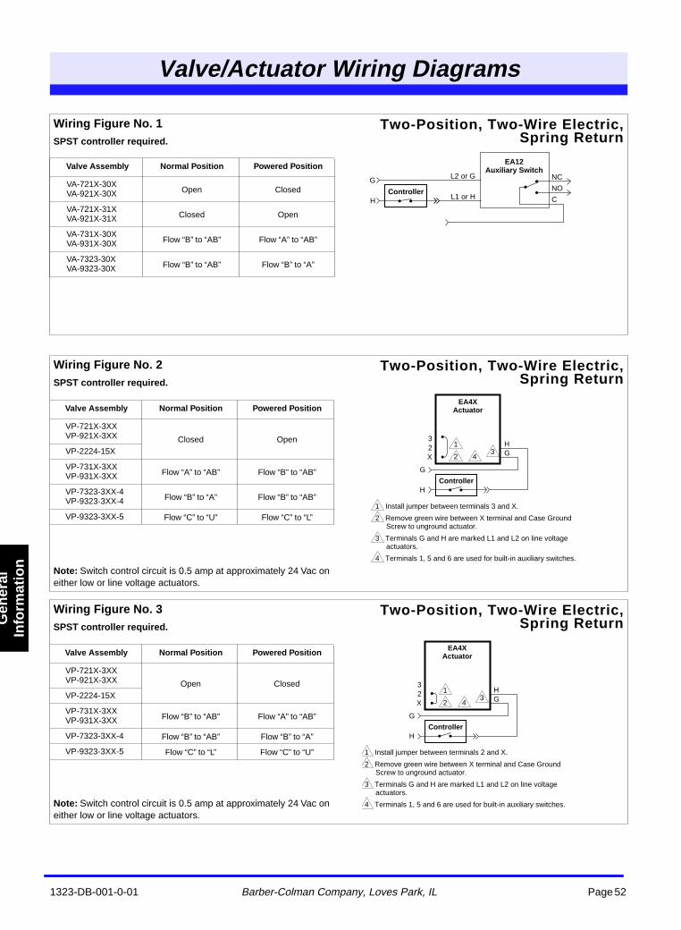
1323-DB-001-0-01 Barber-Colman Company, Loves Park, IL Page 52
Valve/Actuator Wiring Diagrams
Gen
eral
In
form
atio
n
Valve/Aator WiringDiagra
Wiring Figure No. 1 SPST controller required.
Two-Position, Two-Wire Electric,Spring Return
Valve Assembly Normal Position Powered Position
VA-721X-30XVA-921X-30X Open Closed
VA-721X-31XVA-921X-31X Closed Open
VA-731X-30XVA-931X-30X Flow “B” to “AB” Flow “A” to “AB”
VA-7323-30XVA-9323-30X Flow “B” to “AB” Flow “B” to “A”
EA12 Auxiliary Switch
Controller
L2 or G
L1 or HH
G
C
NO
NC
Wiring Figure No. 2 SPST controller required.
Note: Switch control circuit is 0.5 amp at approximately 24 Vac on either low or line voltage actuators.
Two-Position, Two-Wire Electric,Spring Return
Valve Assembly Normal Position Powered Position
VP-721X-3XXVP-921X-3XX Closed OpenVP-2224-15X
VP-731X-3XXVP-931X-3XX Flow “A” to “AB” Flow “B” to “AB”
VP-7323-3XX-4VP-9323-3XX-4 Flow “B” to “A” Flow “B” to “AB”
VP-9323-3XX-5 Flow “C” to “U” Flow “C” to “L”
EA4X Actuator
Controller
GX23
H
G
H
1 Install jumper between terminals 3 and X.
2 Remove green wire between X terminal and Case Ground Screw to unground actuator.
3 Terminals G and H are marked L1 and L2 on line voltage actuators.
4 Terminals 1, 5 and 6 are used for built-in auxiliary switches.
1
2 43
Wiring Figure No. 3 SPST controller required.
Note: Switch control circuit is 0.5 amp at approximately 24 Vac on either low or line voltage actuators.
Two-Position, Two-Wire Electric,Spring Return
Valve Assembly Normal Position Powered Position
VP-721X-3XXVP-921X-3XX Open ClosedVP-2224-15X
VP-731X-3XXVP-931X-3XX Flow “B” to “AB” Flow “A” to “AB”
VP-7323-3XX-4 Flow “B” to “AB” Flow “B” to “A”
VP-9323-3XX-5 Flow “C” to “L” Flow “C” to “U”
EA4X Actuator
Controller
GX23
H
G
H
1 Install jumper between terminals 2 and X.
2 Remove green wire between X terminal and Case Ground Screw to unground actuator.
3 Terminals G and H are marked L1 and L2 on line voltage actuators.
4 Terminals 1, 5 and 6 are used for built-in auxiliary switches.
1
2 43
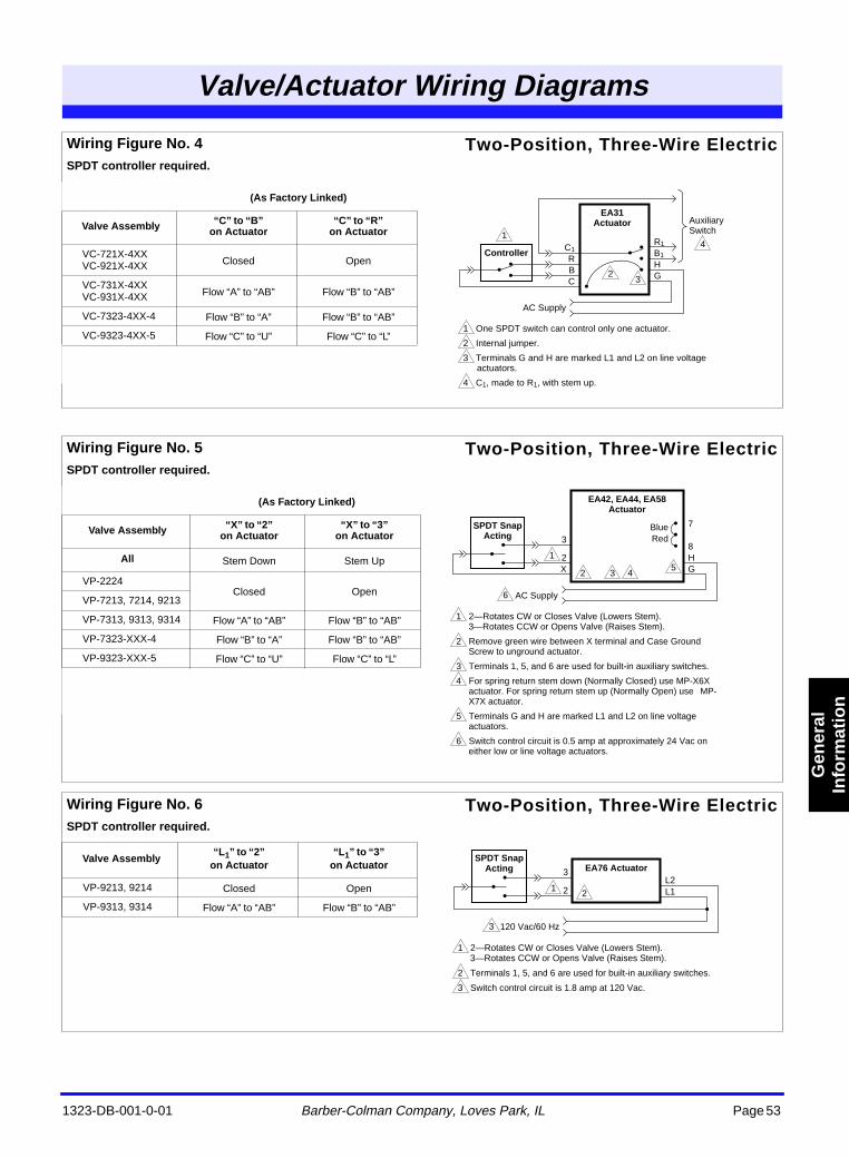
1323-DB-001-0-01 Barber-Colman Company, Loves Park, IL Page 53
Valve/Actuator Wiring Diagrams
Gen
eral
In
form
atio
n
Wiring Figure No. 4 SPDT controller required.
Two-Position, Three-Wire Electric
(As Factory Linked)
Valve Assembly “C” to “B” on Actuator
“C” to “R” on Actuator
VC-721X-4XXVC-921X-4XX Closed Open
VC-731X-4XXVC-931X-4XX Flow “A” to “AB” Flow “B” to “AB”
VC-7323-4XX-4 Flow “B” to “A” Flow “B” to “AB”
VC-9323-4XX-5 Flow “C” to “U” Flow “C” to “L”
EA31 Actuator
Controller
GH
AC Supply
Auxiliary Switch
B1
R1
CBR
C1
1 One SPDT switch can control only one actuator.
2 Internal jumper.
3 Terminals G and H are marked L1 and L2 on line voltage actuators.
4 C1, made to R1, with stem up.
1
2
4
3
Wiring Figure No. 5 SPDT controller required.
Two-Position, Three-Wire Electric
(As Factory Linked)
Valve Assembly “X” to “2”on Actuator
“X” to “3”on Actuator
All Stem Down Stem Up
VP-2224Closed Open
VP-7213, 7214, 9213
VP-7313, 9313, 9314 Flow “A” to “AB” Flow “B” to “AB”
VP-7323-XXX-4 Flow “B” to “A” Flow “B” to “AB”
VP-9323-XXX-5 Flow “C” to “U” Flow “C” to “L”
EA42, EA44, EA58 Actuator
SPDT Snap Acting
GH
AC Supply
8
7
X2
3
1 2—Rotates CW or Closes Valve (Lowers Stem).3—Rotates CCW or Opens Valve (Raises Stem).
2 Remove green wire between X terminal and Case Ground Screw to unground actuator.
3 Terminals 1, 5, and 6 are used for built-in auxiliary switches.
4 For spring return stem down (Normally Closed) use MP-X6X actuator. For spring return stem up (Normally Open) use MP-X7X actuator.
5 Terminals G and H are marked L1 and L2 on line voltage actuators.
6 Switch control circuit is 0.5 amp at approximately 24 Vac on either low or line voltage actuators.
1
2
6
3 45
BlueRed
Wiring Figure No. 6 SPDT controller required.
Two-Position, Three-Wire Electric
Valve Assembly“L1” to “2”
on Actuator“L1” to “3”
on Actuator
VP-9213, 9214 Closed Open
VP-9313, 9314 Flow “A” to “AB” Flow “B” to “AB”
EA76 ActuatorSPDT Snap
Acting
L1L2
120 Vac/60 Hz
2
3
1 2—Rotates CW or Closes Valve (Lowers Stem).3—Rotates CCW or Opens Valve (Raises Stem).
2 Terminals 1, 5, and 6 are used for built-in auxiliary switches.
3 Switch control circuit is 1.8 amp at 120 Vac.
12
3
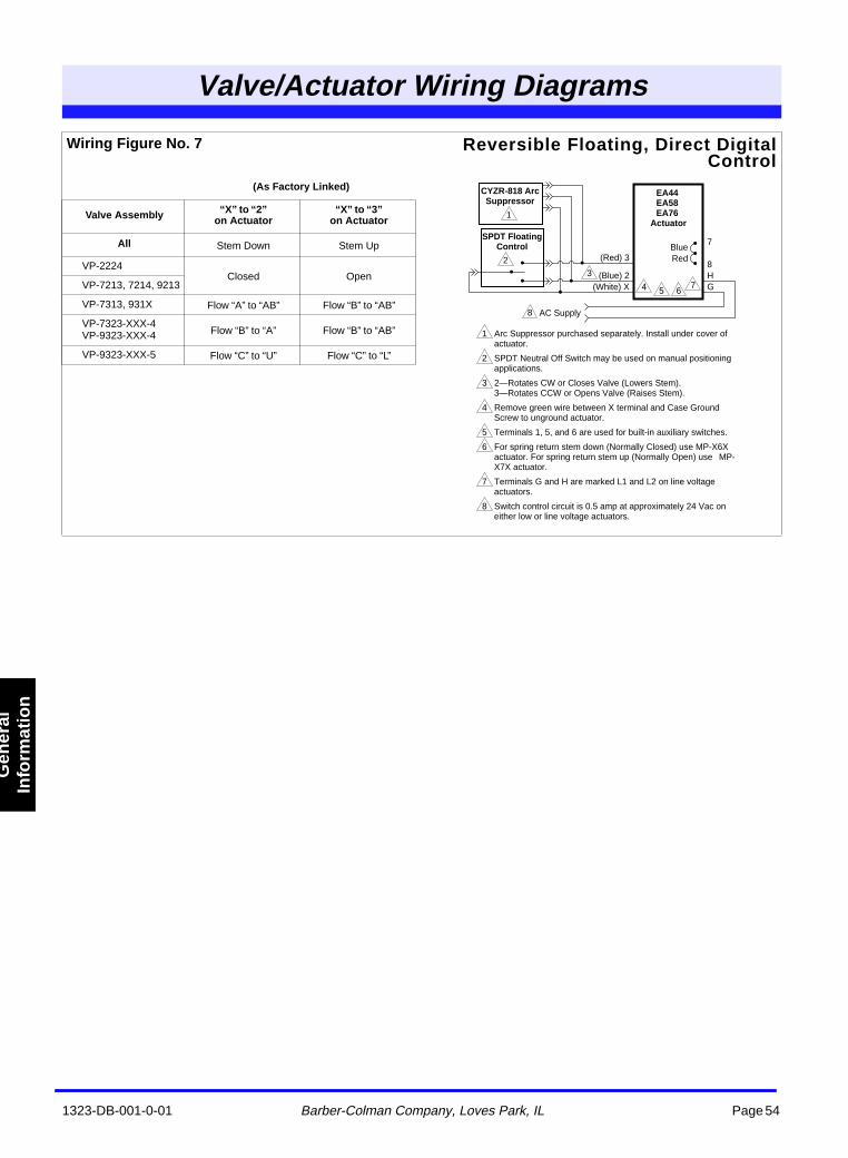
1323-DB-001-0-01 Barber-Colman Company, Loves Park, IL Page 54
Valve/Actuator Wiring Diagrams
Gen
eral
In
form
atio
n
Wiring Figure No. 7 Reversible Floating, Direct DigitalControl
(As Factory Linked)
Valve Assembly “X” to “2”on Actuator
“X” to “3”on Actuator
All Stem Down Stem Up
VP-2224Closed Open
VP-7213, 7214, 9213
VP-7313, 931X Flow “A” to “AB” Flow “B” to “AB”
VP-7323-XXX-4VP-9323-XXX-4 Flow “B” to “A” Flow “B” to “AB”
VP-9323-XXX-5 Flow “C” to “U” Flow “C” to “L”
EA44 EA58 EA76
Actuator
SPDT Floating Control
GH
AC Supply
8
7
(White) X(Blue) 2
(Red) 3
1 Arc Suppressor purchased separately. Install under cover of actuator.
2 SPDT Neutral Off Switch may be used on manual positioning applications.
3 2—Rotates CW or Closes Valve (Lowers Stem).3—Rotates CCW or Opens Valve (Raises Stem).
4 Remove green wire between X terminal and Case Ground Screw to unground actuator.
5 Terminals 1, 5, and 6 are used for built-in auxiliary switches.
6 For spring return stem down (Normally Closed) use MP-X6X actuator. For spring return stem up (Normally Open) use MP-X7X actuator.
7 Terminals G and H are marked L1 and L2 on line voltage actuators.
8 Switch control circuit is 0.5 amp at approximately 24 Vac on either low or line voltage actuators.
4
32
1
8
5 67
CYZR-818 Arc Suppressor
BlueRed
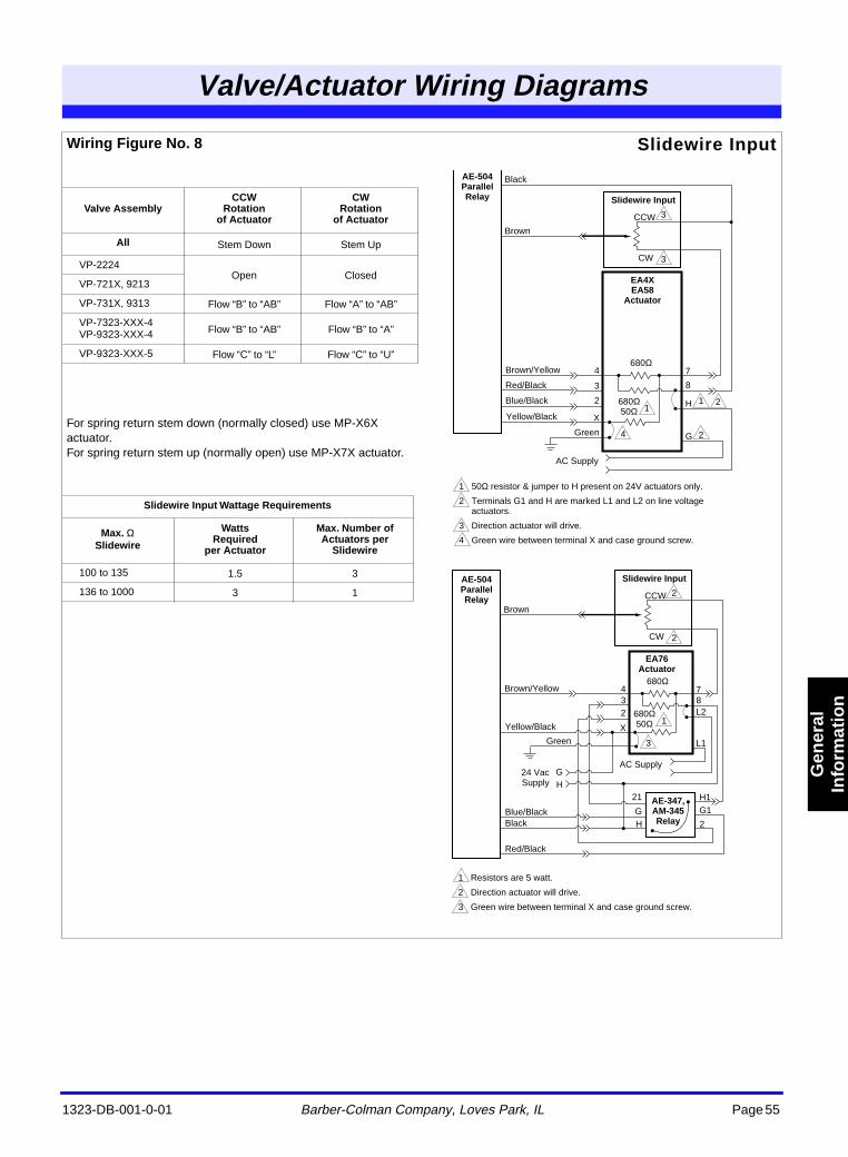
1323-DB-001-0-01 Barber-Colman Company, Loves Park, IL Page 55
Valve/Actuator Wiring Diagrams
Gen
eral
In
form
atio
n
Wiring Figure No. 8
For spring return stem down (normally closed) use MP-X6X actuator. For spring return stem up (normally open) use MP-X7X actuator.
Slidewire Input
Valve AssemblyCCW
Rotationof Actuator
CWRotation
of Actuator
All Stem Down Stem Up
VP-2224Open Closed
VP-721X, 9213
VP-731X, 9313 Flow “B” to “AB” Flow “A” to “AB”
VP-7323-XXX-4VP-9323-XXX-4 Flow “B” to “AB” Flow “B” to “A”
VP-9323-XXX-5 Flow “C” to “L” Flow “C” to “U”
Slidewire Input Wattage Requirements
Max. Ω Slidewire
WattsRequired
per Actuator
Max. Number of Actuators per
Slidewire
100 to 135 1.5 3
136 to 1000 3 1
11
2
3
3
24
7
H
G
8
AE-504 Parallel Relay Slidewire Input
Blue/Black
Yellow/Black
Red/Black
EA4X EA58
Actuator
3
2
Green
X
AC Supply
Brown/Yellow 4
1 50Ω resistor & jumper to H present on 24V actuators only.
2 Terminals G1 and H are marked L1 and L2 on line voltage actuators.
3 Direction actuator will drive.
4 Green wire between terminal X and case ground screw.
CCW
CW
Black
Brown
680Ω 50Ω
680Ω
Yellow/Black
Red/Black
Blue/BlackAE-347, AM-345 Relay
32
X
GH
21
G1
2
H1
Black
1
2
2
3
7
L2
L1
8
AE-504 Parallel Relay
Slidewire Input
EA76 Actuator
Green
AC Supply
Brown/Yellow 4
1 Resistors are 5 watt.
2 Direction actuator will drive.
3 Green wire between terminal X and case ground screw.
CCW
CW
Brown
680Ω 50Ω
680Ω
GH
24 Vac Supply
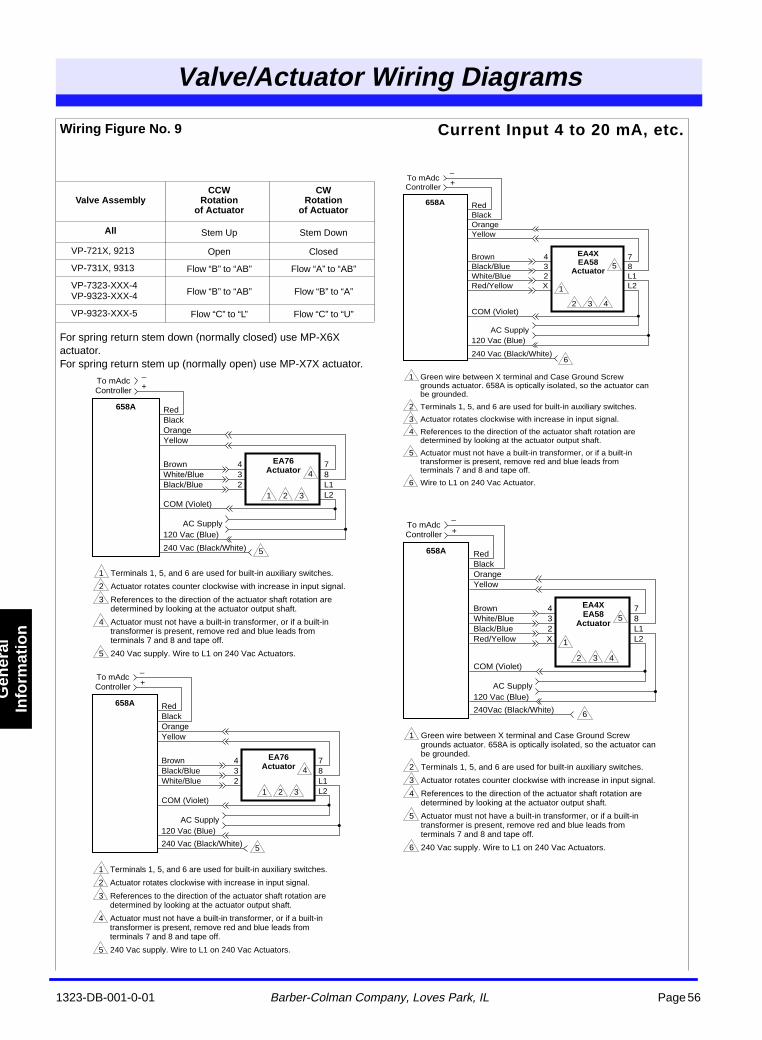
1323-DB-001-0-01 Barber-Colman Company, Loves Park, IL Page 56
Valve/Actuator Wiring Diagrams
Gen
eral
In
form
atio
n
Wiring Figure No. 9
For spring return stem down (normally closed) use MP-X6X actuator. For spring return stem up (normally open) use MP-X7X actuator.
Current Input 4 to 20 mA, etc.
Valve AssemblyCCW
Rotationof Actuator
CWRotation
of Actuator
All Stem Up Stem Down
VP-721X, 9213 Open Closed
VP-731X, 9313 Flow “B” to “AB” Flow “A” to “AB”
VP-7323-XXX-4VP-9323-XXX-4 Flow “B” to “AB” Flow “B” to “A”
VP-9323-XXX-5 Flow “C” to “L” Flow “C” to “U”
+
4
1 2 3
5
658A
EA76 Actuator
Red
432
Black
–
OrangeYellow
BrownWhite/BlueBlack/Blue
78L1L2
COM (Violet)
120 Vac (Blue)
240 Vac (Black/White)
1 Terminals 1, 5, and 6 are used for built-in auxiliary switches.
2 Actuator rotates counter clockwise with increase in input signal.
3 References to the direction of the actuator shaft rotation are determined by looking at the actuator output shaft.
4 Actuator must not have a built-in transformer, or if a built-in transformer is present, remove red and blue leads from terminals 7 and 8 and tape off.
5 240 Vac supply. Wire to L1 on 240 Vac Actuators.
To mAdc Controller
AC Supply
+
4
1 2 3
5
658A
EA76 Actuator
Red
432
Black
–
OrangeYellow
Brown
White/BlueBlack/Blue
78L1L2
COM (Violet)
120 Vac (Blue)
240 Vac (Black/White)
1 Terminals 1, 5, and 6 are used for built-in auxiliary switches.
2 Actuator rotates clockwise with increase in input signal.
3 References to the direction of the actuator shaft rotation are determined by looking at the actuator output shaft.
4 Actuator must not have a built-in transformer, or if a built-in transformer is present, remove red and blue leads from terminals 7 and 8 and tape off.
5 240 Vac supply. Wire to L1 on 240 Vac Actuators.
To mAdc Controller
AC Supply
1
5
2 3 4
6
658A
EA4X EA58
Actuator
Red
432X
Black
+–
OrangeYellow
BrownWhite/BlueBlack/BlueRed/Yellow
78L1L2
COM (Violet)
120 Vac (Blue)
240Vac (Black/White)
1 Green wire between X terminal and Case Ground Screw grounds actuator. 658A is optically isolated, so the actuator can be grounded.
2 Terminals 1, 5, and 6 are used for built-in auxiliary switches.
3 Actuator rotates counter clockwise with increase in input signal.
4 References to the direction of the actuator shaft rotation are determined by looking at the actuator output shaft.
5 Actuator must not have a built-in transformer, or if a built-in transformer is present, remove red and blue leads from terminals 7 and 8 and tape off.
6 240 Vac supply. Wire to L1 on 240 Vac Actuators.
To mAdc Controller
AC Supply
1
6
5
2 3 4
658A
EA4X EA58
Actuator
Red
432X
Black
+–
OrangeYellow
BrownBlack/BlueWhite/BlueRed/Yellow
78L1L2
COM (Violet)
120 Vac (Blue)
240 Vac (Black/White)
1 Green wire between X terminal and Case Ground Screw grounds actuator. 658A is optically isolated, so the actuator can be grounded.
2 Terminals 1, 5, and 6 are used for built-in auxiliary switches.
3 Actuator rotates clockwise with increase in input signal.
4 References to the direction of the actuator shaft rotation are determined by looking at the actuator output shaft.
5 Actuator must not have a built-in transformer, or if a built-in transformer is present, remove red and blue leads from terminals 7 and 8 and tape off.
6 Wire to L1 on 240 Vac Actuator.
To mAdc Controller
AC Supply
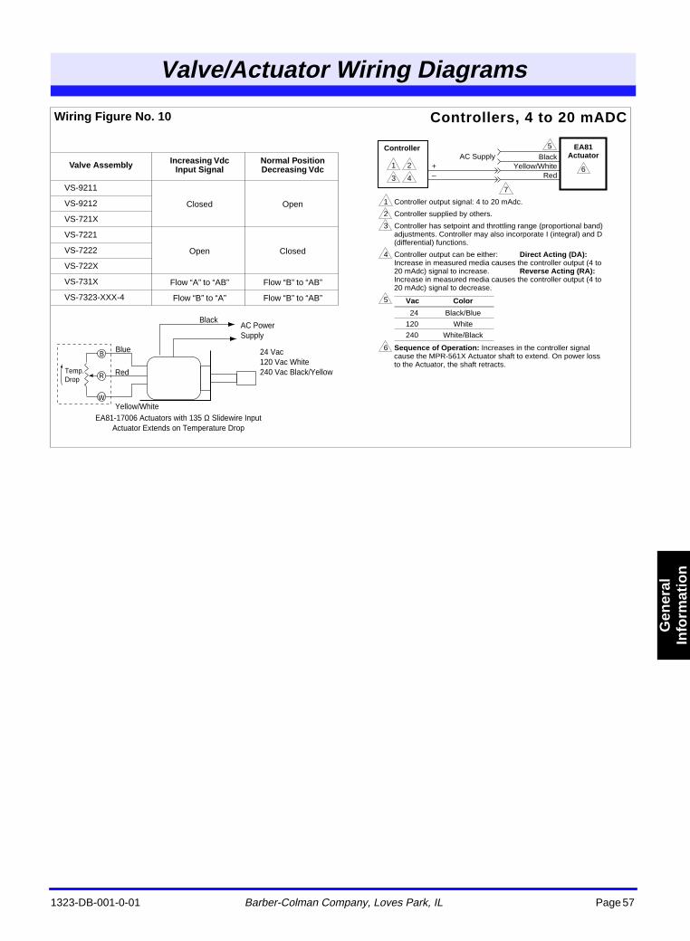
1323-DB-001-0-01 Barber-Colman Company, Loves Park, IL Page 57
Valve/Actuator Wiring Diagrams
Gen
eral
In
form
atio
n
Wiring Figure No. 10 Controllers, 4 to 20 mADC
Valve Assembly Increasing Vdc Input Signal
Normal Position Decreasing Vdc
VS-9211
Closed OpenVS-9212
VS-721X
VS-7221
Open ClosedVS-7222
VS-722X
VS-731X Flow “A” to “AB” Flow “B” to “AB”
VS-7323-XXX-4 Flow “B” to “A” Flow “B” to “AB”
BlackAC Power Supply
24 Vac 120 Vac White 240 Vac Black/Yellow
Blue
Red
Yellow/White
B
R
W
Temp. Drop
EA81-17006 Actuators with 135 Ω Slidewire Input Actuator Extends on Temperature Drop
1 2
3 46
7
5Controller EA81 ActuatorBlack
Yellow/WhiteRed
+–
1 Controller output signal: 4 to 20 mAdc.
2 Controller supplied by others.
3 Controller has setpoint and throttling range (proportional band) adjustments. Controller may also incorporate I (integral) and D (differential) functions.
4 Controller output can be either: Direct Acting (DA): Increase in measured media causes the controller output (4 to 20 mAdc) signal to increase. Reverse Acting (RA): Increase in measured media causes the controller output (4 to 20 mAdc) signal to decrease.
5
6 Sequence of Operation: Increases in the controller signal cause the MPR-561X Actuator shaft to extend. On power loss to the Actuator, the shaft retracts.
AC Supply
Vac Color
24 Black/Blue
120 White
240 White/Black
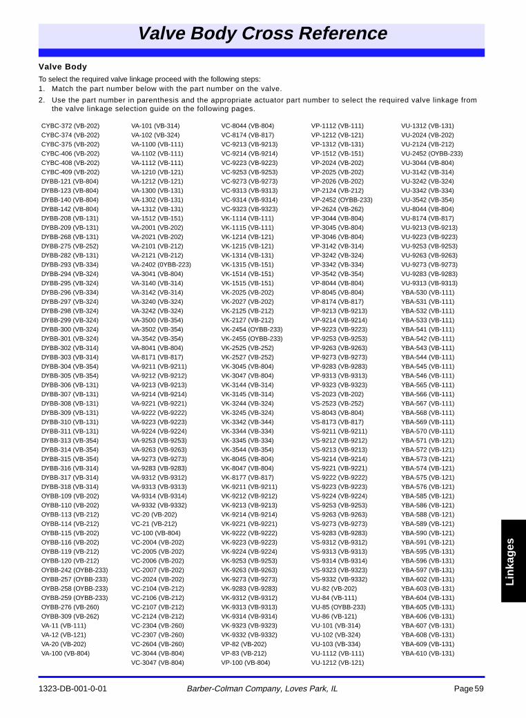
Valve Body Cross Reference
1323-DB-001-0-01 Barber-Colman Company, Loves Park, IL Page 59
Lin
kag
es
Valve BodyTo select the required valve linkage proceed with the following steps:1. Match the part number below with the part number on the valve.
2. Use the part number in parenthesis and the appropriate actuator part number to select the required valve linkage from the valve linkage selection guide on the following pages.
CYBC-372 (VB-202) VA-101 (VB-314) VC-8044 (VB-804) VP-1112 (VB-111) VU-1312 (VB-131)CYBC-374 (VB-202) VA-102 (VB-324) VC-8174 (VB-817) VP-1212 (VB-121) VU-2024 (VB-202)CYBC-375 (VB-202) VA-1100 (VB-111) VC-9213 (VB-9213) VP-1312 (VB-131) VU-2124 (VB-212)CYBC-406 (VB-202) VA-1102 (VB-111) VC-9214 (VB-9214) VP-1512 (VB-151) VU-2452 (OYBB-233)CYBC-408 (VB-202) VA-1112 (VB-111) VC-9223 (VB-9223) VP-2024 (VB-202) VU-3044 (VB-804)CYBC-409 (VB-202) VA-1210 (VB-121) VC-9253 (VB-9253) VP-2025 (VB-202) VU-3142 (VB-314)DYBB-121 (VB-804) VA-1212 (VB-121) VC-9273 (VB-9273) VP-2026 (VB-202) VU-3242 (VB-324)DYBB-123 (VB-804) VA-1300 (VB-131) VC-9313 (VB-9313) VP-2124 (VB-212) VU-3342 (VB-334)DYBB-140 (VB-804) VA-1302 (VB-131) VC-9314 (VB-9314) VP-2452 (OYBB-233) VU-3542 (VB-354)DYBB-142 (VB-804) VA-1312 (VB-131) VC-9323 (VB-9323) VP-2624 (VB-262) VU-8044 (VB-804)DYBB-208 (VB-131) VA-1512 (VB-151) VK-1114 (VB-111) VP-3044 (VB-804) VU-8174 (VB-817)DYBB-209 (VB-131) VA-2001 (VB-202) VK-1115 (VB-111) VP-3045 (VB-804) VU-9213 (VB-9213)DYBB-268 (VB-131) VA-2021 (VB-202) VK-1214 (VB-121) VP-3046 (VB-804) VU-9223 (VB-9223)DYBB-275 (VB-252) VA-2101 (VB-212) VK-1215 (VB-121) VP-3142 (VB-314) VU-9253 (VB-9253)DYBB-282 (VB-131) VA-2121 (VB-212) VK-1314 (VB-131) VP-3242 (VB-324) VU-9263 (VB-9263)DYBB-293 (VB-334) VA-2402 (0YBB-223) VK-1315 (VB-151) VP-3342 (VB-334) VU-9273 (VB-9273)DYBB-294 (VB-324) VA-3041 (VB-804) VK-1514 (VB-151) VP-3542 (VB-354) VU-9283 (VB-9283)DYBB-295 (VB-324) VA-3140 (VB-314) VK-1515 (VB-151) VP-8044 (VB-804) VU-9313 (VB-9313)DYBB-296 (VB-334) VA-3142 (VB-314) VK-2025 (VB-202) VP-8045 (VB-804) YBA-530 (VB-111)DYBB-297 (VB-324) VA-3240 (VB-324) VK-2027 (VB-202) VP-8174 (VB-817) YBA-531 (VB-111)DYBB-298 (VB-324) VA-3242 (VB-324) VK-2125 (VB-212) VP-9213 (VB-9213) YBA-532 (VB-111)DYBB-299 (VB-324) VA-3500 (VB-354) VK-2127 (VB-212) VP-9214 (VB-9214) YBA-533 (VB-111)DYBB-300 (VB-324) VA-3502 (VB-354) VK-2454 (OYBB-233) VP-9223 (VB-9223) YBA-541 (VB-111)DYBB-301 (VB-324) VA-3542 (VB-354) VK-2455 (OYBB-233) VP-9253 (VB-9253) YBA-542 (VB-111)DYBB-302 (VB-314) VA-8041 (VB-804) VK-2525 (VB-252) VP-9263 (VB-9263) YBA-543 (VB-111)DYBB-303 (VB-314) VA-8171 (VB-817) VK-2527 (VB-252) VP-9273 (VB-9273) YBA-544 (VB-111)DYBB-304 (VB-354) VA-9211 (VB-9211) VK-3045 (VB-804) VP-9283 (VB-9283) YBA-545 (VB-111)DYBB-305 (VB-354) VA-9212 (VB-9212) VK-3047 (VB-804) VP-9313 (VB-9313) YBA-546 (VB-111)DYBB-306 (VB-131) VA-9213 (VB-9213) VK-3144 (VB-314) VP-9323 (VB-9323) YBA-565 (VB-111)DYBB-307 (VB-131) VA-9214 (VB-9214) VK-3145 (VB-314) VS-2023 (VB-202) YBA-566 (VB-111)DYBB-308 (VB-131) VA-9221 (VB-9221) VK-3244 (VB-324) VS-2523 (VB-252) YBA-567 (VB-111)DYBB-309 (VB-131) VA-9222 (VB-9222) VK-3245 (VB-324) VS-8043 (VB-804) YBA-568 (VB-111)DYBB-310 (VB-131) VA-9223 (VB-9223) VK-3342 (VB-344) VS-8173 (VB-817) YBA-569 (VB-111)DYBB-311 (VB-131) VA-9224 (VB-9224) VK-3344 (VB-334) VS-9211 (VB-9211) YBA-570 (VB-111)DYBB-313 (VB-354) VA-9253 (VB-9253) VK-3345 (VB-334) VS-9212 (VB-9212) YBA-571 (VB-121)DYBB-314 (VB-354) VA-9263 (VB-9263) VK-3544 (VB-354) VS-9213 (VB-9213) YBA-572 (VB-121)DYBB-315 (VB-354) VA-9273 (VB-9273) VK-8045 (VB-804) VS-9214 (VB-9214) YBA-573 (VB-121)DYBB-316 (VB-314) VA-9283 (VB-9283) VK-8047 (VB-804) VS-9221 (VB-9221) YBA-574 (VB-121)DYBB-317 (VB-314) VA-9312 (VB-9312) VK-8177 (VB-817) VS-9222 (VB-9222) YBA-575 (VB-121)DYBB-318 (VB-314) VA-9313 (VB-9313) VK-9211 (VB-9211) VS-9223 (VB-9223) YBA-576 (VB-121)OYBB-109 (VB-202) VA-9314 (VB-9314) VK-9212 (VB-9212) VS-9224 (VB-9224) YBA-585 (VB-121)OYBB-110 (VB-202) VA-9332 (VB-9332) VK-9213 (VB-9213) VS-9253 (VB-9253) YBA-586 (VB-121)OYBB-113 (VB-212) VC-20 (VB-202) VK-9214 (VB-9214) VS-9263 (VB-9263) YBA-588 (VB-121)OYBB-114 (VB-212) VC-21 (VB-212) VK-9221 (VB-9221) VS-9273 (VB-9273) YBA-589 (VB-121)OYBB-115 (VB-202) VC-100 (VB-804) VK-9222 (VB-9222) VS-9283 (VB-9283) YBA-590 (VB-121)OYBB-116 (VB-202) VC-2004 (VB-202) VK-9223 (VB-9223) VS-9312 (VB-9312) YBA-591 (VB-121)OYBB-119 (VB-212) VC-2005 (VB-202) VK-9224 (VB-9224) VS-9313 (VB-9313) YBA-595 (VB-131)OYBB-120 (VB-212) VC-2006 (VB-202) VK-9253 (VB-9253) VS-9314 (VB-9314) YBA-596 (VB-131)OYBB-242 (OYBB-233) VC-2007 (VB-202) VK-9263 (VB-9263) VS-9323 (VB-9323) YBA-597 (VB-131)OYBB-257 (OYBB-233) VC-2024 (VB-202) VK-9273 (VB-9273) VS-9332 (VB-9332) YBA-602 (VB-131)OYBB-258 (OYBB-233) VC-2104 (VB-212) VK-9283 (VB-9283) VU-82 (VB-202) YBA-603 (VB-131)OYBB-259 (OYBB-233) VC-2106 (VB-212) VK-9312 (VB-9312) VU-84 (VB-111) YBA-604 (VB-131)OYBB-276 (VB-260) VC-2107 (VB-212) VK-9313 (VB-9313) VU-85 (OYBB-233) YBA-605 (VB-131)OYBB-309 (VB-262) VC-2124 (VB-212) VK-9314 (VB-9314) VU-86 (VB-121) YBA-606 (VB-131)VA-11 (VB-111) VC-2304 (VB-260) VK-9323 (VB-9323) VU-101 (VB-314) YBA-607 (VB-131)VA-12 (VB-121) VC-2307 (VB-260) VK-9332 (VB-9332) VU-102 (VB-324) YBA-608 (VB-131)VA-20 (VB-202) VC-2604 (VB-260) VP-82 (VB-202) VU-103 (VB-334) YBA-609 (VB-131)VA-100 (VB-804) VC-3044 (VB-804) VP-83 (VB-212) VU-1112 (VB-111) YBA-610 (VB-131)
VC-3047 (VB-804) VP-100 (VB-804) VU-1212 (VB-121)
s en
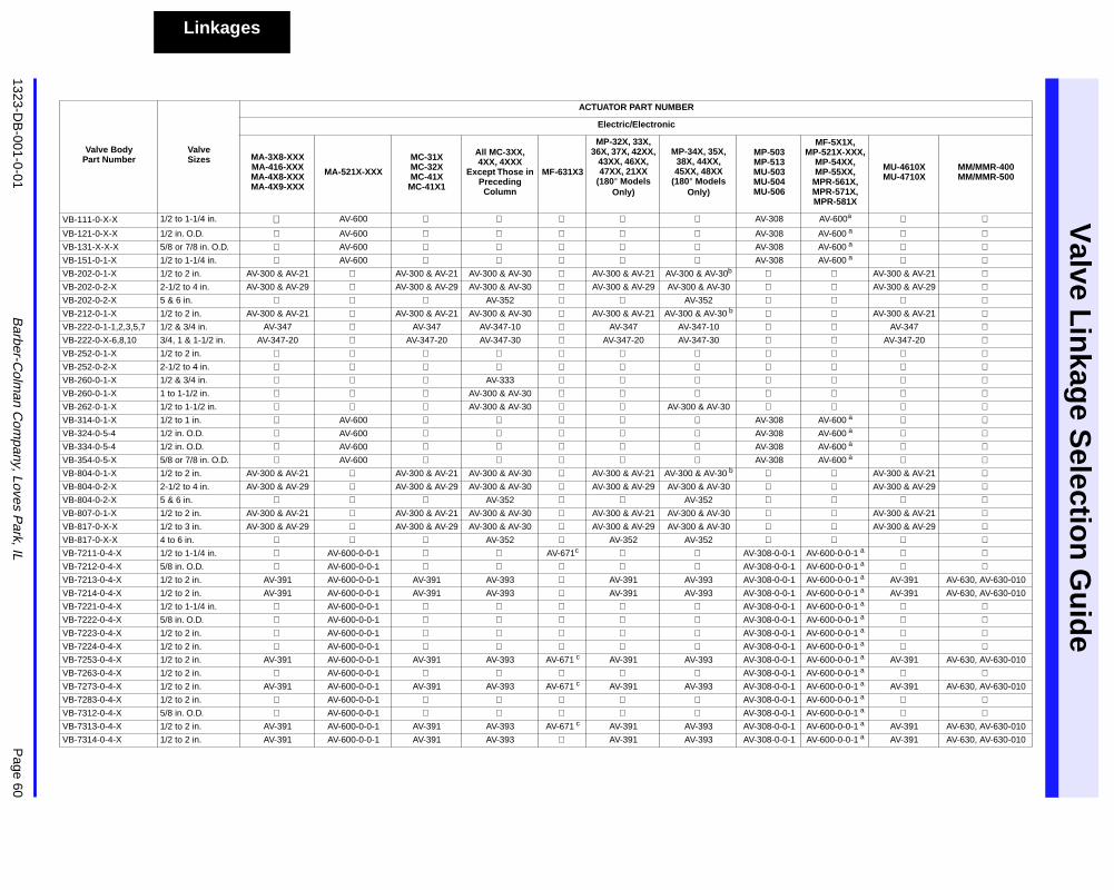
Valve L
inkag
e Selectio
n G
uid
e
1323-DB
-001-0-01
Barber-C
olman C
ompany, Loves P
ark, IL
Page 60
Linkages
Valve BodyPart Number
ValveSizes
ACTUATOR PART NUMBER
Electric/Electronic
MA-3X8-XXX MA-416-XXX MA-4X8-XXX MA-4X9-XXX
MA-521X-XXX
MC-31X MC-32X MC-41X
MC-41X1
All MC-3XX, 4XX, 4XXX
Except Those in Preceding
Column
MF-631X3
MP-32X, 33X, 36X, 37X, 42XX,
43XX, 46XX, 47XX, 21XX
(180
°
Models Only)
MP-34X, 35X, 38X, 44XX, 45XX, 48XX
(180
°
Models Only)
MP-503 MP-513 MU-503 MU-504 MU-506
MF-5X1X, MP-521X-XXX,
MP-54XX, MP-55XX,
MPR-561X, MPR-571X, MPR-581X
MU-4610X MU-4710X
MM/MMR-400 MM/MMR-500
VB-111-0-X-X 1/2 to 1-1/4 in.
AV-600
AV-308 AV-600
a
VB-121-0-X-X 1/2 in. O.D.
AV-600
AV-308 AV-600
a
VB-131-X-X-X 5/8 or 7/8 in. O.D.
AV-600
AV-308 AV-600
a
VB-151-0-1-X 1/2 to 1-1/4 in.
AV-600
AV-308 AV-600
a
VB-202-0-1-X 1/2 to 2 in. AV-300 & AV-21
AV-300 & AV-21 AV-300 & AV-30
AV-300 & AV-21 AV-300 & AV-30
b
AV-300 & AV-21
VB-202-0-2-X 2-1/2 to 4 in. AV-300 & AV-29
AV-300 & AV-29 AV-300 & AV-30
AV-300 & AV-29 AV-300 & AV-30
AV-300 & AV-29
VB-202-0-2-X 5 & 6 in.
AV-352
AV-352
VB-212-0-1-X 1/2 to 2 in. AV-300 & AV-21
AV-300 & AV-21 AV-300 & AV-30
AV-300 & AV-21 AV-300 & AV-30
b
AV-300 & AV-21
VB-222-0-1-1,2,3,5,7 1/2 & 3/4 in. AV-347
AV-347 AV-347-10
AV-347 AV-347-10
AV-347
VB-222-0-X-6,8,10 3/4, 1 & 1-1/2 in. AV-347-20
AV-347-20 AV-347-30
AV-347-20 AV-347-30
AV-347-20
VB-252-0-1-X 1/2 to 2 in.
VB-252-0-2-X 2-1/2 to 4 in.
VB-260-0-1-X 1/2 & 3/4 in.
AV-333
VB-260-0-1-X 1 to 1-1/2 in.
AV-300 & AV-30
VB-262-0-1-X 1/2 to 1-1/2 in.
AV-300 & AV-30
AV-300 & AV-30
VB-314-0-1-X 1/2 to 1 in.
AV-600
AV-308 AV-600
a
VB-324-0-5-4 1/2 in. O.D.
AV-600
AV-308 AV-600
a
VB-334-0-5-4 1/2 in. O.D.
AV-600
AV-308 AV-600
a
VB-354-0-5-X 5/8 or 7/8 in. O.D.
AV-600
AV-308 AV-600
a
VB-804-0-1-X 1/2 to 2 in. AV-300 & AV-21
AV-300 & AV-21 AV-300 & AV-30
AV-300 & AV-21 AV-300 & AV-30
b
AV-300 & AV-21
VB-804-0-2-X 2-1/2 to 4 in. AV-300 & AV-29
AV-300 & AV-29 AV-300 & AV-30
AV-300 & AV-29 AV-300 & AV-30
AV-300 & AV-29
VB-804-0-2-X 5 & 6 in.
AV-352
AV-352
VB-807-0-1-X 1/2 to 2 in. AV-300 & AV-21
AV-300 & AV-21 AV-300 & AV-30
AV-300 & AV-21 AV-300 & AV-30
AV-300 & AV-21
VB-817-0-X-X 1/2 to 3 in. AV-300 & AV-29
AV-300 & AV-29 AV-300 & AV-30
AV-300 & AV-29 AV-300 & AV-30
AV-300 & AV-29
VB-817-0-X-X 4 to 6 in.
AV-352
AV-352 AV-352
VB-7211-0-4-X 1/2 to 1-1/4 in.
AV-600-0-0-1
AV-671
c
AV-308-0-0-1 AV-600-0-0-1
a
VB-7212-0-4-X 5/8 in. O.D.
AV-600-0-0-1
AV-308-0-0-1 AV-600-0-0-1
a
VB-7213-0-4-X 1/2 to 2 in. AV-391 AV-600-0-0-1 AV-391 AV-393
AV-391 AV-393 AV-308-0-0-1 AV-600-0-0-1
a
AV-391 AV-630, AV-630-010
VB-7214-0-4-X 1/2 to 2 in. AV-391 AV-600-0-0-1 AV-391 AV-393
AV-391 AV-393 AV-308-0-0-1 AV-600-0-0-1
a
AV-391 AV-630, AV-630-010
VB-7221-0-4-X 1/2 to 1-1/4 in.
AV-600-0-0-1
AV-308-0-0-1 AV-600-0-0-1
a
VB-7222-0-4-X 5/8 in. O.D.
AV-600-0-0-1
AV-308-0-0-1 AV-600-0-0-1
a
VB-7223-0-4-X 1/2 to 2 in.
AV-600-0-0-1
AV-308-0-0-1 AV-600-0-0-1
a
VB-7224-0-4-X 1/2 to 2 in.
AV-600-0-0-1
AV-308-0-0-1 AV-600-0-0-1
a
VB-7253-0-4-X 1/2 to 2 in. AV-391 AV-600-0-0-1 AV-391 AV-393 AV-671
c
AV-391 AV-393 AV-308-0-0-1 AV-600-0-0-1
a
AV-391 AV-630, AV-630-010
VB-7263-0-4-X 1/2 to 2 in.
AV-600-0-0-1
AV-308-0-0-1 AV-600-0-0-1
a
VB-7273-0-4-X 1/2 to 2 in. AV-391 AV-600-0-0-1 AV-391 AV-393 AV-671
c
AV-391 AV-393 AV-308-0-0-1 AV-600-0-0-1
a
AV-391 AV-630, AV-630-010
VB-7283-0-4-X 1/2 to 2 in.
AV-600-0-0-1
AV-308-0-0-1 AV-600-0-0-1
a
VB-7312-0-4-X 5/8 in. O.D.
AV-600-0-0-1
AV-308-0-0-1 AV-600-0-0-1
a
VB-7313-0-4-X 1/2 to 2 in. AV-391 AV-600-0-0-1 AV-391 AV-393 AV-671
c
AV-391 AV-393 AV-308-0-0-1 AV-600-0-0-1
a
AV-391 AV-630, AV-630-010
VB-7314-0-4-X 1/2 to 2 in. AV-391 AV-600-0-0-1 AV-391 AV-393
AV-391 AV-393 AV-308-0-0-1 AV-600-0-0-1
a
AV-391 AV-630, AV-630-010
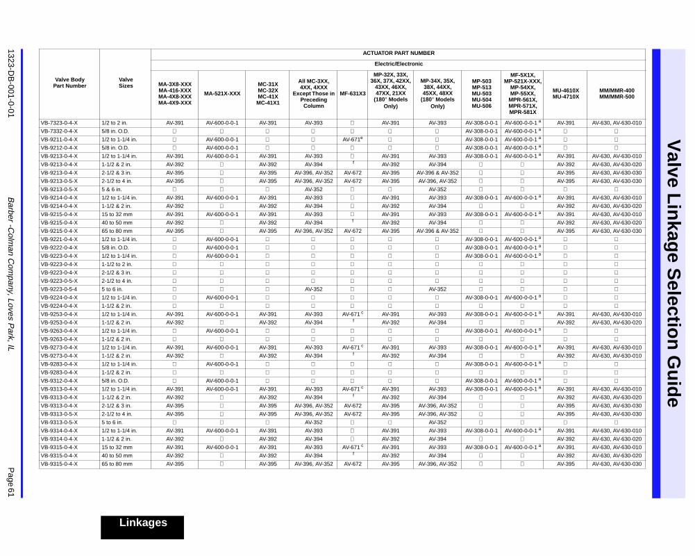
1323-DB
-001-0-01
Barber -C
olman C
ompany, Loves P
ark, IL
Page 61
Valve L
inkag
e Selectio
n G
uid
e
Linkages
VB-7323-0-4-X 1/2 to 2 in. AV-391 AV-600-0-0-1 AV-391 AV-393
AV-391 AV-393 AV-308-0-0-1 AV-600-0-0-1
a
AV-391 AV-630, AV-630-010
VB-7332-0-4-X 5/8 in. O.D.
AV-308-0-0-1 AV-600-0-0-1
a
VB-9211-0-4-X 1/2 to 1-1/4 in.
AV-600-0-0-1
AV-671
e
AV-308-0-0-1 AV-600-0-0-1
a
VB-9212-0-4-X 5/8 in. O.D.
AV-600-0-0-1
AV-308-0-0-1 AV-600-0-0-1
a
VB-9213-0-4-X 1/2 to 1-1/4 in. AV-391 AV-600-0-0-1 AV-391 AV-393
AV-391 AV-393 AV-308-0-0-1 AV-600-0-0-1
a
AV-391 AV-630, AV-630-010
VB-9213-0-4-X 1-1/2 & 2 in. AV-392
AV-392 AV-394
f
AV-392 AV-394
AV-392 AV-630, AV-630-020
VB-9213-0-4-X 2-1/2 & 3 in. AV-395
AV-395 AV-396, AV-352 AV-672 AV-395 AV-396 & AV-352
AV-395 AV-630, AV-630-030
VB-9213-0-5-X 2-1/2 to 4 in. AV-395
AV-395 AV-396, AV-352 AV-672 AV-395 AV-396, AV-352
AV-395 AV-630, AV-630-030
VB-9213-0-5-X 5 & 6 in.
AV-352
AV-352
VB-9214-0-4-X 1/2 to 1-1/4 in. AV-391 AV-600-0-0-1 AV-391 AV-393
AV-391 AV-393 AV-308-0-0-1 AV-600-0-0-1
a
AV-391 AV-630, AV-630-010
VB-9214-0-4-X 1-1/2 & 2 in. AV-392
AV-392 AV-394
AV-392 AV-394
AV-392 AV-630, AV-630-020
VB-9215-0-4-X 15 to 32 mm AV-391 AV-600-0-0-1 AV-391 AV-393
AV-391 AV-393 AV-308-0-0-1 AV-600-0-0-1
a
AV-391 AV-630, AV-630-010
VB-9215-0-4-X 40 to 50 mm AV-392
AV-392 AV-394
f
AV-392 AV-394
AV-392 AV-630, AV-630-020
VB-9215-0-4-X 65 to 80 mm AV-395
AV-395 AV-396, AV-352 AV-672 AV-395 AV-396 & AV-352
AV-395 AV-630, AV-630-030
VB-9221-0-4-X 1/2 to 1-1/4 in.
AV-600-0-0-1
AV-308-0-0-1 AV-600-0-0-1
a
VB-9222-0-4-X 5/8 in. O.D.
AV-600-0-0-1
AV-308-0-0-1 AV-600-0-0-1 a VB-9223-0-4-X 1/2 to 1-1/4 in. AV-600-0-0-1 AV-308-0-0-1 AV-600-0-0-1 a VB-9223-0-4-X 1-1/2 to 2 in. VB-9223-0-4-X 2-1/2 & 3 in. VB-9223-0-5-X 2-1/2 to 4 in. VB-9223-0-5-4 5 to 6 in. AV-352 AV-352 VB-9224-0-4-X 1/2 to 1-1/4 in. AV-600-0-0-1 AV-308-0-0-1 AV-600-0-0-1 a VB-9224-0-4-X 1-1/2 & 2 in. VB-9253-0-4-X 1/2 to 1-1/4 in. AV-391 AV-600-0-0-1 AV-391 AV-393 AV-671 c AV-391 AV-393 AV-308-0-0-1 AV-600-0-0-1 a AV-391 AV-630, AV-630-010
VB-9253-0-4-X 1-1/2 & 2 in. AV-392 AV-392 AV-394 f AV-392 AV-394 AV-392 AV-630, AV-630-020
VB-9263-0-4-X 1/2 to 1-1/4 in. AV-600-0-0-1 AV-308-0-0-1 AV-600-0-0-1 a VB-9263-0-4-X 1-1/2 & 2 in. VB-9273-0-4-X 1/2 to 1-1/4 in. AV-391 AV-600-0-0-1 AV-391 AV-393 AV-671 c AV-391 AV-393 AV-308-0-0-1 AV-600-0-0-1 a AV-391 AV-630, AV-630-010
VB-9273-0-4-X 1-1/2 & 2 in. AV-392 AV-392 AV-394 f AV-392 AV-394 AV-392 AV-630, AV-630-010
VB-9283-0-4-X 1/2 to 1-1/4 in. AV-600-0-0-1 AV-308-0-0-1 AV-600-0-0-1 a VB-9283-0-4-X 1-1/2 & 2 in. VB-9312-0-4-X 5/8 in. O.D. AV-600-0-0-1 AV-308-0-0-1 AV-600-0-0-1 a VB-9313-0-4-X 1/2 to 1-1/4 in. AV-391 AV-600-0-0-1 AV-391 AV-393 AV-671 c AV-391 AV-393 AV-308-0-0-1 AV-600-0-0-1 a AV-391 AV-630, AV-630-010
VB-9313-0-4-X 1-1/2 & 2 in. AV-392 AV-392 AV-394 f AV-392 AV-394 AV-392 AV-630, AV-630-020
VB-9313-0-4-X 2-1/2 & 3 in. AV-395 AV-395 AV-396, AV-352 AV-672 AV-395 AV-396, AV-352 AV-395 AV-630, AV-630-030
VB-9313-0-5-X 2-1/2 to 4 in. AV-395 AV-395 AV-396, AV-352 AV-672 AV-395 AV-396, AV-352 AV-395 AV-630, AV-630-030
VB-9313-0-5-X 5 to 6 in. AV-352 AV-352 VB-9314-0-4-X 1/2 to 1-1/4 in. AV-391 AV-600-0-0-1 AV-391 AV-393 AV-391 AV-393 AV-308-0-0-1 AV-600-0-0-1 a AV-391 AV-630, AV-630-010
VB-9314-0-4-X 1-1/2 & 2 in. AV-392 AV-392 AV-394 AV-392 AV-394 AV-392 AV-630, AV-630-020
VB-9315-0-4-X 15 to 32 mm AV-391 AV-600-0-0-1 AV-391 AV-393 AV-671 c AV-391 AV-393 AV-308-0-0-1 AV-600-0-0-1 a AV-391 AV-630, AV-630-010
VB-9315-0-4-X 40 to 50 mm AV-392 AV-392 AV-394 f AV-392 AV-394 AV-392 AV-630, AV-630-020
VB-9315-0-4-X 65 to 80 mm AV-395 AV-395 AV-396, AV-352 AV-672 AV-395 AV-396, AV-352 AV-395 AV-630, AV-630-030
Valve BodyPart Number
ValveSizes
ACTUATOR PART NUMBER
Electric/Electronic
MA-3X8-XXX MA-416-XXX MA-4X8-XXX MA-4X9-XXX
MA-521X-XXX
MC-31X MC-32X MC-41X
MC-41X1
All MC-3XX, 4XX, 4XXX
Except Those in Preceding
Column
MF-631X3
MP-32X, 33X, 36X, 37X, 42XX,
43XX, 46XX, 47XX, 21XX
(180° Models Only)
MP-34X, 35X, 38X, 44XX, 45XX, 48XX
(180° Models Only)
MP-503 MP-513 MU-503 MU-504 MU-506
MF-5X1X, MP-521X-XXX,
MP-54XX, MP-55XX,
MPR-561X, MPR-571X, MPR-581X
MU-4610X MU-4710X
MM/MMR-400 MM/MMR-500
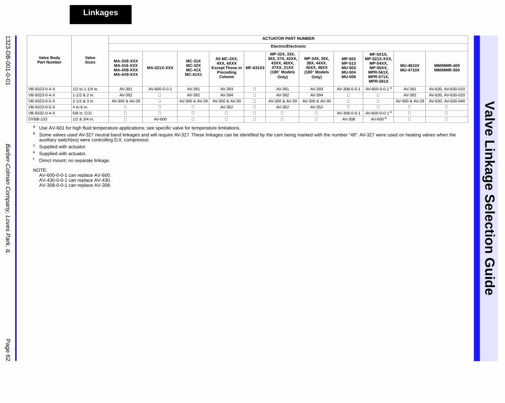
Valve L
inkag
e Selectio
n G
uid
e
1323-DB
-001-0-01B
arber-Colm
an Com
pany, Loves Park, IL
Page 62
Linkages
NOTE:AV-600-0-0-1 can replace AV-600.AV-430-0-0-1 can replace AV-430.AV-308-0-0-1 can replace AV-308.
a Use AV-601 for high fluid temperature applications; see specific valve for temperature limitations.b Some valves used AV-327 neutral band linkages and will require AV-327. These linkages can be identified by the cam being marked with the number “49”. AV-327 were used on heating valves when the
auxiliary switch(es) were controlling D.X. compressor.c Supplied with actuator.e Supplied with actuator.f Direct mount; no separate linkage.
VB-9323-0-4-X 1/2 to 1-1/4 in. AV-391 AV-600-0-0-1 AV-391 AV-393 AV-391 AV-393 AV-308-0-0-1 AV-600-0-0-1 a AV-391 AV-630, AV-630-010
VB-9323-0-4-X 1-1/2 & 2 in. AV-392 AV-392 AV-394 AV-392 AV-394 AV-392 AV-630, AV-630-020
VB-9323-0-5-X 2-1/2 & 3 in. AV-300 & AV-29 AV-300 & AV-29 AV-300 & AV-30 AV-300 & AV-29 AV-300 & AV-30 AV-300 & AV-29 AV-630, AV-630-040
VB-9323-0-5-X 4 to 6 in. AV-352 AV-352 AV-352 VB-9332-0-4-X 5/8 in. O.D. AV-308-0-0-1 AV-600-0-0-1 a OYBB-233 1/2 & 3/4 in. AV-600 AV-308 AV-600 a
Valve BodyPart Number
ValveSizes
ACTUATOR PART NUMBER
Electric/Electronic
MA-3X8-XXX MA-416-XXX MA-4X8-XXX MA-4X9-XXX
MA-521X-XXX
MC-31X MC-32X MC-41X
MC-41X1
All MC-3XX, 4XX, 4XXX
Except Those in Preceding
Column
MF-631X3
MP-32X, 33X, 36X, 37X, 42XX,
43XX, 46XX, 47XX, 21XX
(180° Models Only)
MP-34X, 35X, 38X, 44XX, 45XX, 48XX
(180° Models Only)
MP-503 MP-513 MU-503 MU-504 MU-506
MF-5X1X, MP-521X-XXX,
MP-54XX, MP-55XX,
MPR-561X, MPR-571X, MPR-581X
MU-4610X MU-4710X
MM/MMR-400 MM/MMR-500
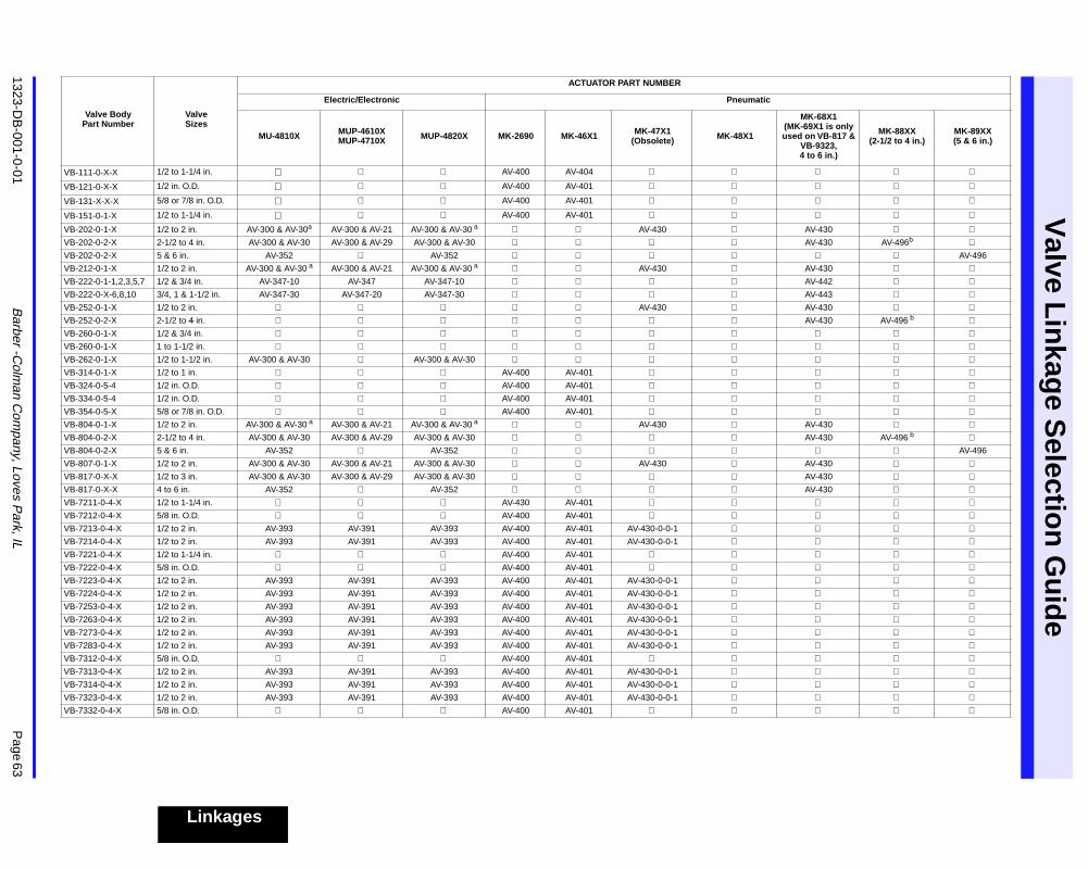
1323-DB
-001-0-01B
arber -Colm
an Com
pany, Loves Park, IL
Page 63
Valve L
inkag
e Selectio
n G
uid
e
Linkages
Valve BodyPart Number
ValveSizes
ACTUATOR PART NUMBER
Electric/Electronic Pneumatic
MU-4810X MUP-4610X MUP-4710X MUP-4820X MK-2690 MK-46X1 MK-47X1
(Obsolete) MK-48X1
MK-68X1 (MK-69X1 is only used on VB-817 &
VB-9323, 4 to 6 in.)
MK-88XX(2-1/2 to 4 in.)
MK-89XX(5 & 6 in.)
VB-111-0-X-X 1/2 to 1-1/4 in. AV-400 AV-404
VB-121-0-X-X 1/2 in. O.D. AV-400 AV-401
VB-131-X-X-X 5/8 or 7/8 in. O.D. AV-400 AV-401
VB-151-0-1-X 1/2 to 1-1/4 in. AV-400 AV-401
VB-202-0-1-X 1/2 to 2 in. AV-300 & AV-30a AV-300 & AV-21 AV-300 & AV-30 a AV-430 AV-430 VB-202-0-2-X 2-1/2 to 4 in. AV-300 & AV-30 AV-300 & AV-29 AV-300 & AV-30 AV-430 AV-496b VB-202-0-2-X 5 & 6 in. AV-352 AV-352 AV-496
VB-212-0-1-X 1/2 to 2 in. AV-300 & AV-30 a AV-300 & AV-21 AV-300 & AV-30 a AV-430 AV-430 VB-222-0-1-1,2,3,5,7 1/2 & 3/4 in. AV-347-10 AV-347 AV-347-10 AV-442 VB-222-0-X-6,8,10 3/4, 1 & 1-1/2 in. AV-347-30 AV-347-20 AV-347-30 AV-443 VB-252-0-1-X 1/2 to 2 in. AV-430 AV-430 VB-252-0-2-X 2-1/2 to 4 in. AV-430 AV-496 b VB-260-0-1-X 1/2 & 3/4 in. VB-260-0-1-X 1 to 1-1/2 in. VB-262-0-1-X 1/2 to 1-1/2 in. AV-300 & AV-30 AV-300 & AV-30 VB-314-0-1-X 1/2 to 1 in. AV-400 AV-401 VB-324-0-5-4 1/2 in. O.D. AV-400 AV-401 VB-334-0-5-4 1/2 in. O.D. AV-400 AV-401 VB-354-0-5-X 5/8 or 7/8 in. O.D. AV-400 AV-401 VB-804-0-1-X 1/2 to 2 in. AV-300 & AV-30 a AV-300 & AV-21 AV-300 & AV-30 a AV-430 AV-430 VB-804-0-2-X 2-1/2 to 4 in. AV-300 & AV-30 AV-300 & AV-29 AV-300 & AV-30 AV-430 AV-496 b VB-804-0-2-X 5 & 6 in. AV-352 AV-352 AV-496
VB-807-0-1-X 1/2 to 2 in. AV-300 & AV-30 AV-300 & AV-21 AV-300 & AV-30 AV-430 AV-430 VB-817-0-X-X 1/2 to 3 in. AV-300 & AV-30 AV-300 & AV-29 AV-300 & AV-30 AV-430 VB-817-0-X-X 4 to 6 in. AV-352 AV-352 AV-430 VB-7211-0-4-X 1/2 to 1-1/4 in. AV-430 AV-401 VB-7212-0-4-X 5/8 in. O.D. AV-400 AV-401 VB-7213-0-4-X 1/2 to 2 in. AV-393 AV-391 AV-393 AV-400 AV-401 AV-430-0-0-1 VB-7214-0-4-X 1/2 to 2 in. AV-393 AV-391 AV-393 AV-400 AV-401 AV-430-0-0-1 VB-7221-0-4-X 1/2 to 1-1/4 in. AV-400 AV-401 VB-7222-0-4-X 5/8 in. O.D. AV-400 AV-401 VB-7223-0-4-X 1/2 to 2 in. AV-393 AV-391 AV-393 AV-400 AV-401 AV-430-0-0-1 VB-7224-0-4-X 1/2 to 2 in. AV-393 AV-391 AV-393 AV-400 AV-401 AV-430-0-0-1 VB-7253-0-4-X 1/2 to 2 in. AV-393 AV-391 AV-393 AV-400 AV-401 AV-430-0-0-1 VB-7263-0-4-X 1/2 to 2 in. AV-393 AV-391 AV-393 AV-400 AV-401 AV-430-0-0-1 VB-7273-0-4-X 1/2 to 2 in. AV-393 AV-391 AV-393 AV-400 AV-401 AV-430-0-0-1 VB-7283-0-4-X 1/2 to 2 in. AV-393 AV-391 AV-393 AV-400 AV-401 AV-430-0-0-1 VB-7312-0-4-X 5/8 in. O.D. AV-400 AV-401 VB-7313-0-4-X 1/2 to 2 in. AV-393 AV-391 AV-393 AV-400 AV-401 AV-430-0-0-1 VB-7314-0-4-X 1/2 to 2 in. AV-393 AV-391 AV-393 AV-400 AV-401 AV-430-0-0-1 VB-7323-0-4-X 1/2 to 2 in. AV-393 AV-391 AV-393 AV-400 AV-401 AV-430-0-0-1 VB-7332-0-4-X 5/8 in. O.D. AV-400 AV-401
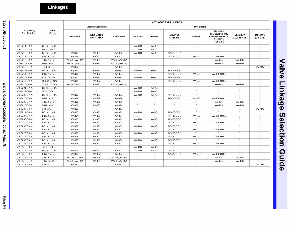
Valve L
inkag
e Selectio
n G
uid
e
1323-DB
-001-0-01B
arber-Colm
an Com
pany, Loves Park, IL
Page 64
Linkages
VB-9211-0-4-X 1/2 to 1-1/4 in. AV-430 AV-401 VB-9212-0-4-X 5/8 in. O.D. AV-400 AV-401 VB-9213-0-4-X 1/2 to 1-1/4 in. AV-393 AV-391 AV-393 AV-400 AV-401 AV-430-0-0-1 VB-9213-0-4-X 1-1/2 & 2 in. AV-394 AV-392 AV-394 AV-430-0-0-1 AV-420 AV-430-0-0-1 VB-9213-0-4-X 2-1/2 & 3 in. AV-396, AV-352 AV-395 AV-396, AV-352 AV-495 AV-496 VB-9213-0-5-X 2-1/2 to 4 in. AV-396, AV-352 AV-395 AV-396, AV-352 AV-495 AV-496 VB-9213-0-5-X 5 & 6 in. AV-352 AV-352 AV-496
VB-9214-0-4-X 1/2 to 1-1/4 in. AV-393 AV-391 AV-393 AV-400 AV-401 AV-430-0-0-1 VB-9214-0-4-X 1-1/2 & 2 in. AV-394 AV-392 AV-394 AV-430-0-0-1 AV-420 AV-430-0-0-1 VB-9215-0-4-X 15 to 32 mm AV-393 AV-391 AV-393 AV-400 AV-401 AV-430-0-0-1 VB-9215-0-4-X 40 and 50 mm AV-394 AV-392 AV-394 AV-430-0-0-1 AV-420 AV-430-0-0-1 VB-9215-0-4-X 65 and 80 mm AV-396, AV-352 AV-395 AV-396, AV-352 AV-495 AV-496 VB-9221-0-4-X 1/2 to 1-1/4 in. AV-400 AV-401 VB-9222-0-4-X 5/8 in. O.D. AV-400 AV-401 VB-9223-0-4-X 1/2 to 1-1/4 in. AV-393 AV-391 AV-393 AV-400 AV-401 AV-430-0-0-1 VB-9223-0-4-X 1-1/2 to 2 in. AV-394 AV-392 AV-394 AV-430-0-0-1 AV-420 AV-430-0-0-1 VB-9223-0-4-X 2-1/2 & 3 in. AV-396 AV-395 AV-396 AV-495 AV-496 VB-9223-0-5-X 2-1/2 to 4 in. AV-396 AV-395 AV-396 AV-495 AV-496 VB-9223-0-5-4 5 to 6 in. AV-352 AV-352 AV-496
VB-9224-0-4-X 1/2 to 1-1/4 in. AV-393 AV-391 AV-393 AV-400 AV-401 AV-430-0-0-1 VB-9224-0-4-X 1-1/2 & 2 in. AV-394 AV-392 AV-394 AV-430-0-0-1 AV-420 AV-430-0-0-1 VB-9253-0-4-X 1/2 to 1-1/4 in. AV-393 AV-391 AV-393 AV-400 AV-401 AV-430-0-0-1 VB-9253-0-4-X 1-1/2 & 2 in. AV-394 AV-392 AV-394 AV-430-0-0-1 AV-420 AV-430-0-0-1 VB-9263-0-4-X 1/2 to 1-1/4 in. AV-393 AV-391 AV-393 AV-400 AV-401 AV-430-0-0-1 VB-9263-0-4-X 1-1/2 & 2 in. AV-394 AV-392 AV-394 AV-430-0-0-1 AV-420 AV-430-0-0-1 VB-9273-0-4-X 1/2 to 1-1/4 in. AV-393 AV-391 AV-393 AV-400 AV-401 AV-430-0-0-1 VB-9273-0-4-X 1-1/2 & 2 in. AV-394 AV-392 AV-394 AV-430-0-0-1 AV-420 AV-430-0-0-1 VB-9283-0-4-X 1/2 to 1-1/4 in. AV-393 AV-391 AV-393 AV-400 AV-401 AV-430-0-0-1 VB-9283-0-4-X 1-1/2 & 2 in. AV-394 AV-392 AV-394 AV-430-0-0-1 AV-420 AV-430-0-0-1 VB-9312-0-4-X 5/8 in. O.D. AV-400 AV-401 VB-9313-0-4-X 1/2 to 1-1/4 in. AV-393 AV-391 AV-393 AV-400 AV-401 AV-430-0-0-1 VB-9313-0-4-X 1-1/2 & 2 in. AV-394 AV-392 AV-394 AV-430-0-0-1 AV-420 AV-430-0-0-1 VB-9313-0-4-X 2-1/2 & 3 in. AV-396, AV-352 AV-395 AV-396, AV-352 AV-495 AV-496 VB-9313-0-5-X 2-1/2 to 4 in. AV-396, AV-352 AV-395 AV-396, AV-352 AV-495 AV-496 VB-9313-0-5-X 5 to 6 in. AV-352 AV-352 AV-496
Valve BodyPart Number
ValveSizes
ACTUATOR PART NUMBER
Electric/Electronic Pneumatic
MU-4810X MUP-4610X MUP-4710X MUP-4820X MK-2690 MK-46X1 MK-47X1
(Obsolete) MK-48X1
MK-68X1 (MK-69X1 is only used on VB-817 &
VB-9323, 4 to 6 in.)
MK-88XX(2-1/2 to 4 in.)
MK-89XX(5 & 6 in.)
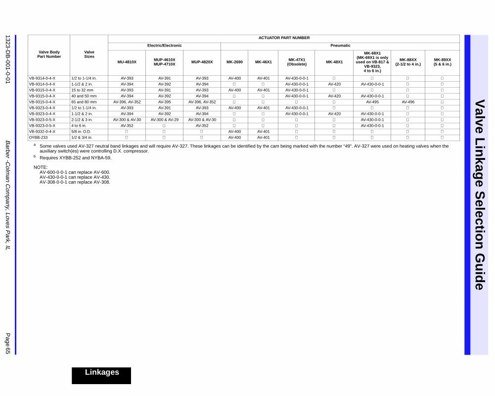
1323-DB
-001-0-01B
arber -Colm
an Com
pany, Loves Park, IL
Page 65
Valve L
inkag
e Selectio
n G
uid
e
Linkages
NOTE:AV-600-0-0-1 can replace AV-600.AV-430-0-0-1 can replace AV-430.AV-308-0-0-1 can replace AV-308.
a Some valves used AV-327 neutral band linkages and will require AV-327. These linkages can be identified by the cam being marked with the number “49”. AV-327 were used on heating valves when theauxiliary switch(es) were controlling D.X. compressor.
b Requires XYBB-252 and NYBA-59.
VB-9314-0-4-X 1/2 to 1-1/4 in. AV-393 AV-391 AV-393 AV-400 AV-401 AV-430-0-0-1 VB-9314-0-4-X 1-1/2 & 2 in. AV-394 AV-392 AV-394 AV-430-0-0-1 AV-420 AV-430-0-0-1 VB-9315-0-4-X 15 to 32 mm AV-393 AV-391 AV-393 AV-400 AV-401 AV-430-0-0-1 VB-9315-0-4-X 40 and 50 mm AV-394 AV-392 AV-394 AV-430-0-0-1 AV-420 AV-430-0-0-1 VB-9315-0-4-X 65 and 80 mm AV-396, AV-352 AV-395 AV-396, AV-352 AV-495 AV-496 VB-9323-0-4-X 1/2 to 1-1/4 in. AV-393 AV-391 AV-393 AV-400 AV-401 AV-430-0-0-1 VB-9323-0-4-X 1-1/2 & 2 in. AV-394 AV-392 AV-394 AV-430-0-0-1 AV-420 AV-430-0-0-1 VB-9323-0-5-X 2-1/2 & 3 in. AV-300 & AV-30 AV-300 & AV-29 AV-300 & AV-30 AV-430-0-0-1 VB-9323-0-5-X 4 to 6 in. AV-352 AV-352 AV-430-0-0-1 VB-9332-0-4-X 5/8 in. O.D. AV-400 AV-401 OYBB-233 1/2 & 3/4 in. AV-400 AV-401
Valve BodyPart Number
ValveSizes
ACTUATOR PART NUMBER
Electric/Electronic Pneumatic
MU-4810X MUP-4610X MUP-4710X MUP-4820X MK-2690 MK-46X1 MK-47X1
(Obsolete) MK-48X1
MK-68X1 (MK-69X1 is only used on VB-817 &
VB-9323, 4 to 6 in.)
MK-88XX(2-1/2 to 4 in.)
MK-89XX(5 & 6 in.)
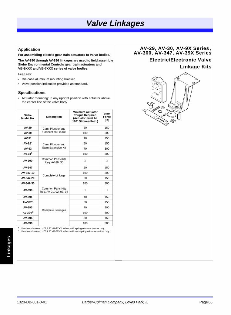
1323-DB-001-0-01 Barber-Colman Company, Loves Park, IL Page 66
Valve Linkages
Lin
kag
es
ApplicationFor assembling electric gear train actuators to valve bodies.
The AV-390 through AV-396 linkages are used to field assemble Siebe Environmental Controls gear train actuators and VB-9XXX and VB-7XXX series of valve bodies.
Features:
• Die case aluminum mounting bracket.
• Valve position indication provided as standard.
Specifications• Actuator mounting: In any upright position with actuator above
the center line of the valve body.
AV-29, AV-30, AV-9X Series ,AV-300, AV-347, AV-39X Series
Electric/Electronic ValveLinkage Kits
Valve Linkage
SiebeModel No. Description
Minimum Actuator Torque Required
(Actuator must be 180° Stroke) (lb-in.)
Stem Force
(lb)
AV-29 Cam, Plunger and Connection Pin Kit
50 150
AV-30 100 300
AV-91
Cam, Plunger and Stem Extension Kit
40 150
AV-92a 50 150
AV-93 70 300
AV-94b 100 300
AV-300 Common Parts Kits Req. AV-29, 30
AV-347
Complete Linkage
50 150
AV-347-10 100 300
AV-347-20 50 150
AV-347-30 100 300
AV-390 Common Parts KitsReq. AV-91, 92, 93, 94
AV-391
Complete Linkages
40 150
AV-392a 50 150
AV-393 70 300
AV-394b 100 300
AV-395 50 150
AV-396 100 300
a Used on obsolete 1-1/2 & 2” VB-9XXX valves with spring return actuators only.b Used on obsolete 1-1/2 & 2” VB-9XXX valves with non-spring return actuators only.
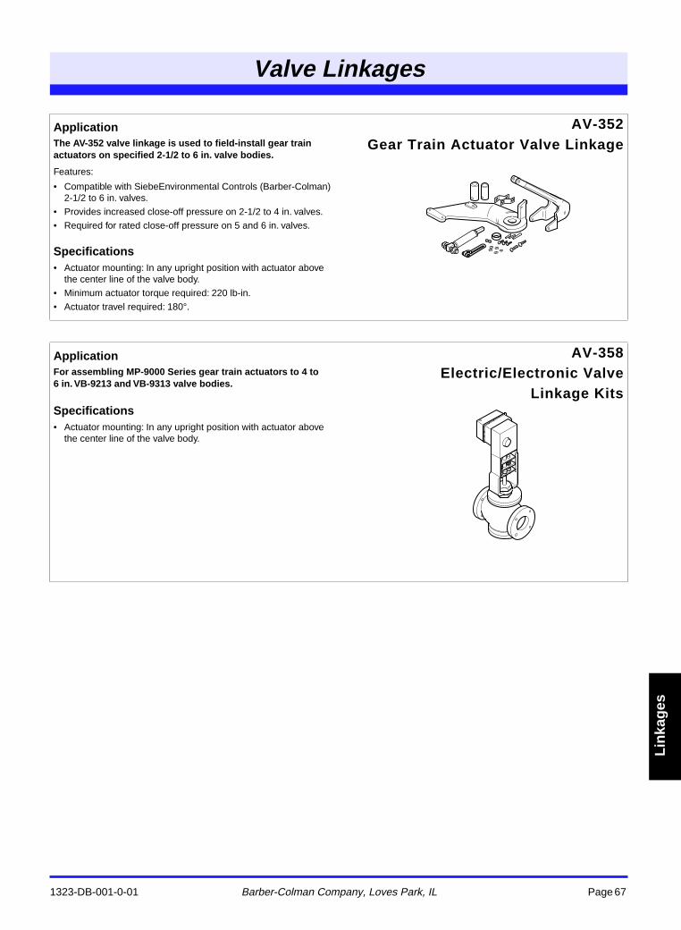
1323-DB-001-0-01 Barber-Colman Company, Loves Park, IL Page 67
Valve Linkages
Lin
kag
es
ApplicationThe AV-352 valve linkage is used to field-install gear train actuators on specified 2-1/2 to 6 in. valve bodies.
Features:
• Compatible with SiebeEnvironmental Controls (Barber-Colman) 2-1/2 to 6 in. valves.
• Provides increased close-off pressure on 2-1/2 to 4 in. valves.
• Required for rated close-off pressure on 5 and 6 in. valves.
Specifications• Actuator mounting: In any upright position with actuator above
the center line of the valve body.
• Minimum actuator torque required: 220 lb-in.
• Actuator travel required: 180°.
AV-352Gear Train Actuator Valve Linkage
ApplicationFor assembling MP-9000 Series gear train actuators to 4 to 6 in. VB-9213 and VB-9313 valve bodies.
Specifications• Actuator mounting: In any upright position with actuator above
the center line of the valve body.
AV-358Electric/Electronic Valve
Linkage Kits
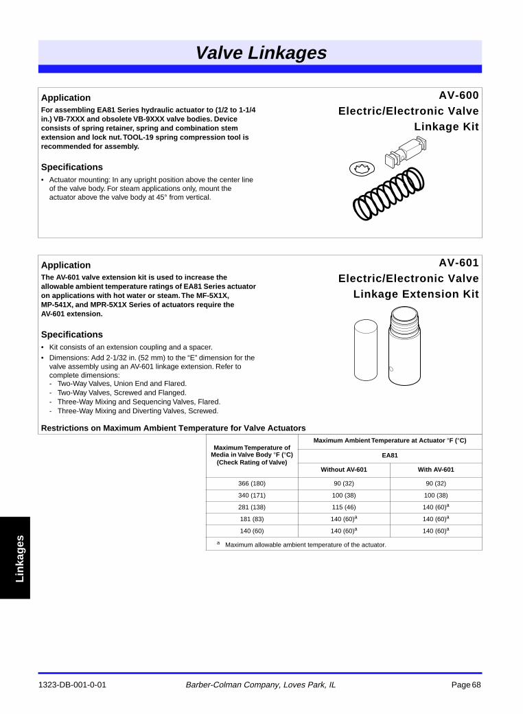
1323-DB-001-0-01 Barber-Colman Company, Loves Park, IL Page 68
Valve Linkages
Lin
kag
es
ApplicationFor assembling EA81 Series hydraulic actuator to (1/2 to 1-1/4 in.) VB-7XXX and obsolete VB-9XXX valve bodies. Device consists of spring retainer, spring and combination stem extension and lock nut. TOOL-19 spring compression tool is recommended for assembly.
Specifications• Actuator mounting: In any upright position above the center line
of the valve body. For steam applications only, mount the actuator above the valve body at 45° from vertical.
AV-600Electric/Electronic Valve
Linkage Kit
ApplicationThe AV-601 valve extension kit is used to increase the allowable ambient temperature ratings of EA81 Series actuator on applications with hot water or steam. The MF-5X1X, MP-541X, and MPR-5X1X Series of actuators require the AV-601 extension.
Specifications• Kit consists of an extension coupling and a spacer.
• Dimensions: Add 2-1/32 in. (52 mm) to the “E” dimension for the valve assembly using an AV-601 linkage extension. Refer to complete dimensions:- Two-Way Valves, Union End and Flared.- Two-Way Valves, Screwed and Flanged.- Three-Way Mixing and Sequencing Valves, Flared.- Three-Way Mixing and Diverting Valves, Screwed.
AV-601Electric/Electronic Valve
Linkage Extension Kit
Restrictions on Maximum Ambient Temperature for Valve Actuators
Maximum Temperature of Media in Valve Body °F (°C)
(Check Rating of Valve)
Maximum Ambient Temperature at Actuator °F (°C)
EA81
Without AV-601 With AV-601
366 (180) 90 (32) 90 (32)
340 (171) 100 (38) 100 (38)
281 (138) 115 (46) 140 (60)a
181 (83) 140 (60)a 140 (60)a
140 (60) 140 (60)a 140 (60)a
a Maximum allowable ambient temperature of the actuator.
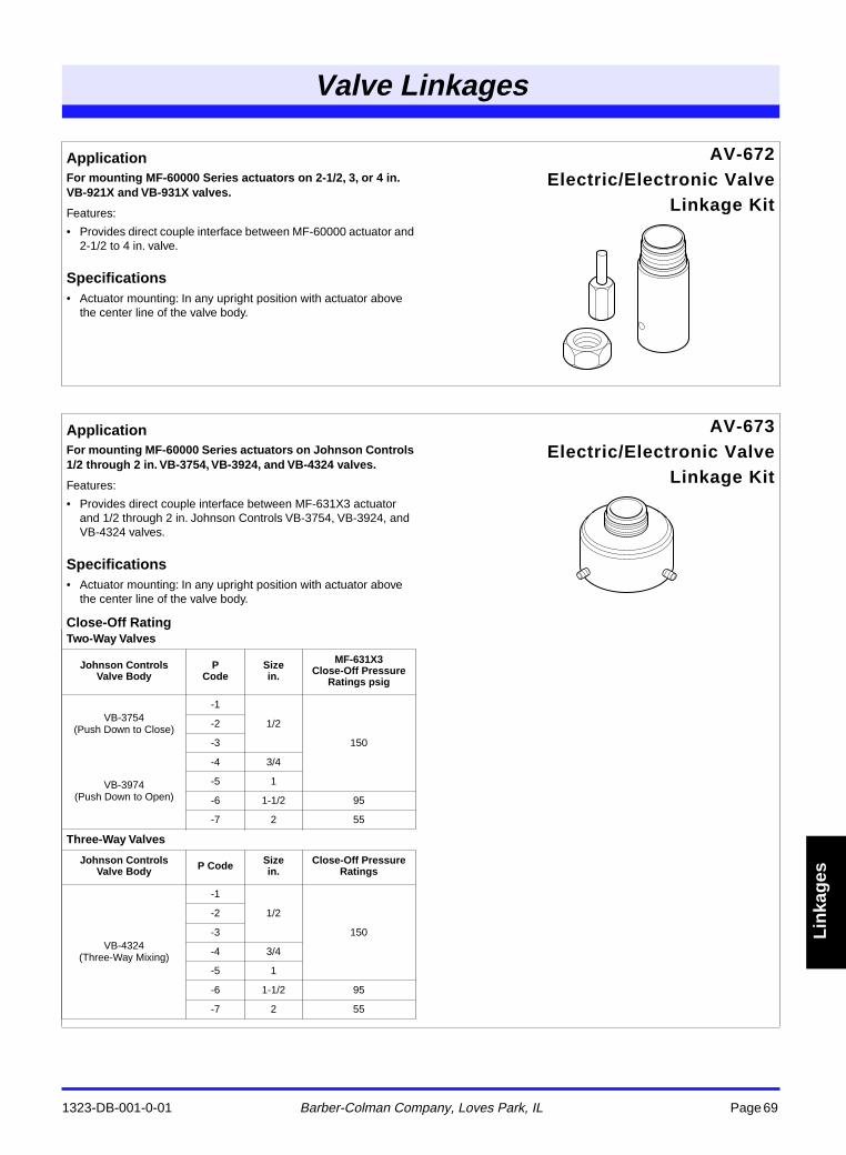
1323-DB-001-0-01 Barber-Colman Company, Loves Park, IL Page 69
Valve Linkages
Lin
kag
es
ApplicationFor mounting MF-60000 Series actuators on 2-1/2, 3, or 4 in. VB-921X and VB-931X valves.
Features:
• Provides direct couple interface between MF-60000 actuator and 2-1/2 to 4 in. valve.
Specifications• Actuator mounting: In any upright position with actuator above
the center line of the valve body.
AV-672Electric/Electronic Valve
Linkage Kit
ApplicationFor mounting MF-60000 Series actuators on Johnson Controls 1/2 through 2 in. VB-3754, VB-3924, and VB-4324 valves.
Features:
• Provides direct couple interface between MF-631X3 actuator and 1/2 through 2 in. Johnson Controls VB-3754, VB-3924, and VB-4324 valves.
Specifications• Actuator mounting: In any upright position with actuator above
the center line of the valve body.
Close-Off Rating
AV-673Electric/Electronic Valve
Linkage Kit
Two-Way Valves
Johnson Controls Valve Body
PCode
Sizein.
MF-631X3Close-Off Pressure
Ratings psig
VB-3754(Push Down to Close)
-1
1/2
150
-2
-3
VB-3974(Push Down to Open)
-4 3/4
-5 1
-6 1-1/2 95
-7 2 55
Three-Way Valves
Johnson Controls Valve Body P Code Size
in.Close-Off Pressure
Ratings
VB-4324(Three-Way Mixing)
-1
1/2
150
-2
-3
-4 3/4
-5 1
-6 1-1/2 95
-7 2 55
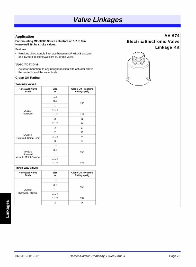
1323-DB-001-0-01 Barber-Colman Company, Loves Park, IL Page 70
Valve Linkages
Lin
kag
es
ApplicationFor mounting MF-60000 Series actuators on 1/2 to 3 in. Honeywell 3/4 in. stroke valves.
Features:
• Provides direct couple interface between MF-631X3 actuator and 1/2 to 3 in. Honeywell 3/4 in. stroke valve.
Specifications• Actuator mounting: In any upright position with actuator above
the center line of the valve body.
Close-Off Rating
AV-674Electric/Electronic Valve
Linkage Kit
Two-Way Valves
Honeywell Valve Body
Sizein.
Close-Off Pressure Ratings psig
V5011F(Screwed)
1/2
1503/4
1
1-1/4
1-1/2 123
2 75
2-1/2 44
3 27
V5011G(Screwed, Comp. Disc)
2 75
2-1/2 44
3 27
V5011G(Screwed,
Metal-to-Metal Seating)
1/2
1503/4
1
1-1/4
1-1/2 123
Three-Way Valves
Honeywell Valve Body
Sizein.
Close-Off Pressure Ratings psig
V5013F(Screwed, Mixing)
1/2
1503/4
1
1-1/4
1-1/2 137
2 96
Distributed Worldwide by www.mcgoff-bethune.com Email: [email protected] +1-770-840-9811
Warranty
Products are warranted according to the General Warranty Statement that is part of the Terms and Conditions of Sale of the Industrial Instruments Division (Literature Part No. 0001-GI-015-0-XX), Barber-Colman Company.
Barber-Colman CompanyIndustrial Instruments Division