Embed Size (px)
Citation preview
CAUTIONS AND WARNINGS . . . . . . . . . . 2SYSTEM COMPATIBILITY . . . . . . . . . . . . 3FEATURES . . . . . . . . . . . . . . . . . . . . . . . 4TOOLS YOU MAY NEED . . . . . . . . . . . . . . 4MOUNTING LOCATION . . . . . . . . . . . . . . 5REMOVE OLD THERMOSTAT . . . . . . . . . . 5INSTALL THERMOSTAT BASE . . . . . . . . . 6WIRING INFORMATION . . . . . . . . . . . . . . 6WIRING DIAGRAMS . . . . . . . . . . . . . . . . 8HARDWARE SETUP OPTIONS . . . . . . . . 17
COMPLETE THE INSTALL . . . . . . . . . . . 19FRONT PANEL ITEMS . . . . . . . . . . . . . . 19OPERATING INSTRUCTIONS . . . . . . . . . 21TEMPERATURE PROGRAMS . . . . . . . . . 23ADVANCED FEATURES . . . . . . . . . . . . . 24BATTERY REPLACEMENT . . . . . . . . . . . 31TECHNICAL ASSISTANCE . . . . . . . . . . . 31LIMITED WARRANTY . . . . . . . . . . . . . . 32MERCURY NOTICE . . . . . . . . . . . . . . . . 32
WARNING: Use Energizer® or DURACELL® Alkaline Batteries Only.Energizer® is a registered trademark of Eveready Battery Company, Inc.DURACELL® is a registered trademark of The Procter & Gamble Company
© 2013 LUX PRODUCTS CORPORATION. ALL RIGHTS RESERVED
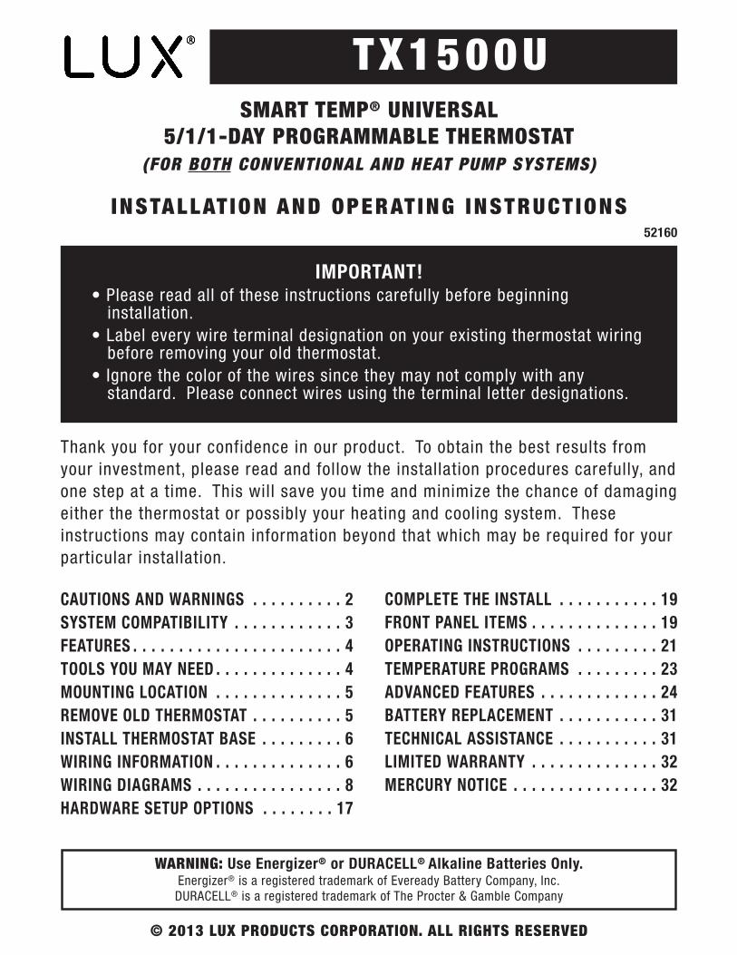
TX1500USMART TEMP® UNIVERSAL
5/1/1-DAY PROGRAMMABLE THERMOSTAT(FOR BOTH CONVENTIONAL AND HEAT PUMP SYSTEMS)
INSTALLAT ION AND OPERAT ING INSTRUCT IONS
IMPORTANT!• Please read all of these instructions carefully before beginning
installation.• Label every wire terminal designation on your existing thermostat wiring
before removing your old thermostat.• Ignore the color of the wires since they may not comply with any
standard. Please connect wires using the terminal letter designations.
Thank you for your confidence in our product. To obtain the best results fromyour investment, please read and follow the installation procedures carefully, andone step at a time. This will save you time and minimize the chance of damagingeither the thermostat or possibly your heating and cooling system. Theseinstructions may contain information beyond that which may be required for yourparticular installation.
52160
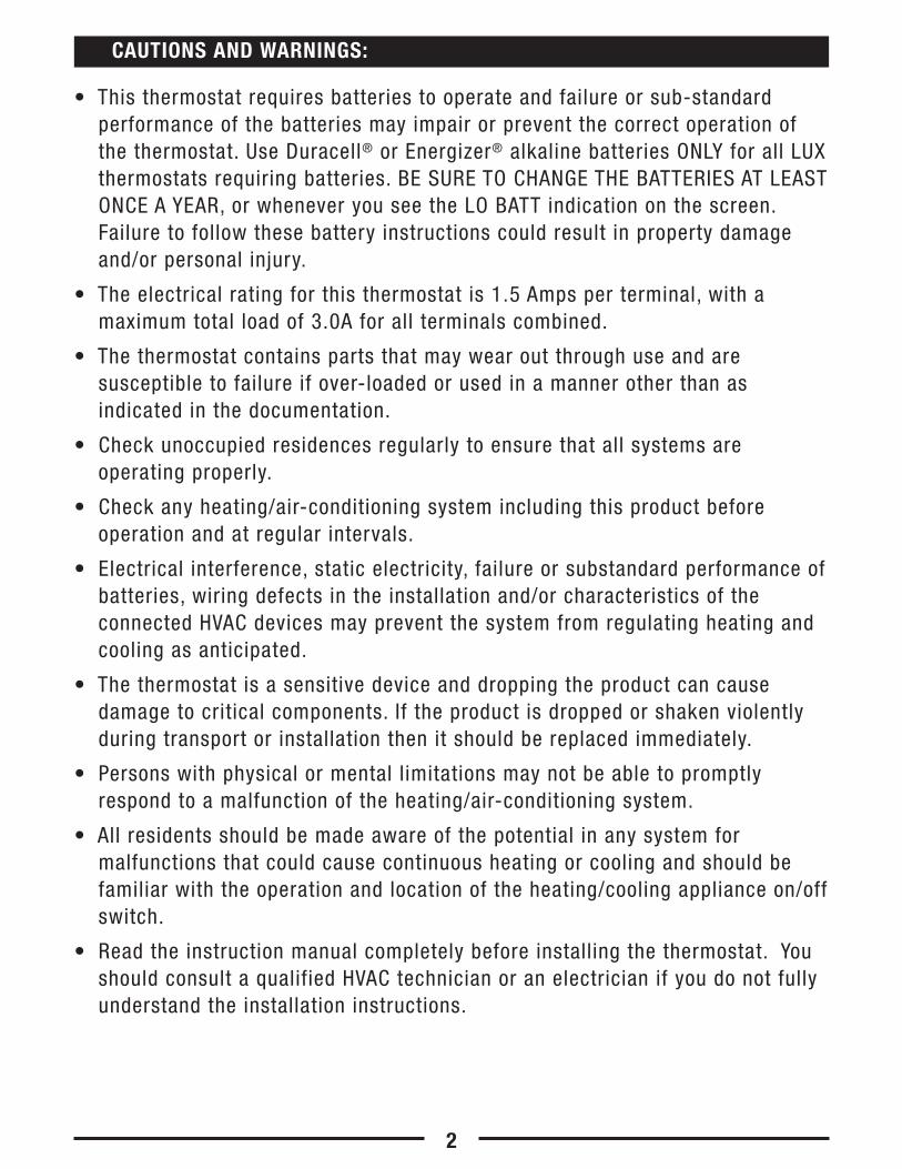
• This thermostat requires batteries to operate and failure or sub-standardperformance of the batteries may impair or prevent the correct operation ofthe thermostat. Use Duracell® or Energizer® alkaline batteries ONLY for all LUXthermostats requiring batteries. BE SURE TO CHANGE THE BATTERIES AT LEASTONCE A YEAR, or whenever you see the LO BATT indication on the screen.Failure to follow these battery instructions could result in property damageand/or personal injury.
• The electrical rating for this thermostat is 1.5 Amps per terminal, with amaximum total load of 3.0A for all terminals combined.
• The thermostat contains parts that may wear out through use and aresusceptible to failure if over-loaded or used in a manner other than asindicated in the documentation.
• Check unoccupied residences regularly to ensure that all systems areoperating properly.
• Check any heating/air-conditioning system including this product beforeoperation and at regular intervals.
• Electrical interference, static electricity, failure or substandard performance ofbatteries, wiring defects in the installation and/or characteristics of theconnected HVAC devices may prevent the system from regulating heating andcooling as anticipated.
• The thermostat is a sensitive device and dropping the product can causedamage to critical components. If the product is dropped or shaken violentlyduring transport or installation then it should be replaced immediately.
• Persons with physical or mental limitations may not be able to promptlyrespond to a malfunction of the heating/air-conditioning system.
• All residents should be made aware of the potential in any system formalfunctions that could cause continuous heating or cooling and should befamiliar with the operation and location of the heating/cooling appliance on/offswitch.
• Read the instruction manual completely before installing the thermostat. Youshould consult a qualified HVAC technician or an electrician if you do not fullyunderstand the installation instructions.
2
CAUTIONS AND WARNINGS:

SETBACK HOLD
SET
RUN
DAY/TIME
TEMP PROG
AIR FILTER
TEMPERATURE
HEAT
OFF
COOL
FAN
AUTO
ON
EMER
NEXT
74F̊72F̊
5:36P
HEAT
TUDAY
SET
FAN
40%LEFTFILTER
LCD Display ScreenTX1500U
UP / DOWN Buttons
Set SlideSwitch
Fan ModeSwitch
System ModeSwitch
The electrical rating for this thermostat is 1.5 Amps per terminal, with amaximum total combined load of 3.0A for all terminals combined.
COMPATIBLE WITH:• Most 24-volt heating and cooling systems• 1 or 2 stage Heat / 1 stage Cool: Gas, Oil or Electric systems• 1 or 2 stage Heat / 1 stage Cool: Heat Pump systems• 3-wire hydronic (hot water) zone valves• Gas Millivolt heaters
NOT COMPATIBLE WITH:• 120/240 VAC line-voltage systems (without a transformer), ask your LUX
dealer for thermostats to control these systems.
SYSTEM COMPATIBILITY:
3

• 1 or 2-Heat / 1-Cool, 5/1/1-day programming• Universal Compatibility for all system types• Weekdays, Saturday, and Sunday can be programmed separately• Exclusive LUX® Speed SlideTM for easy programming• User-selectable periods per day (2 or 4)• User-selectable programmable or non-programmable operation• LuxLight® EL (Electro-Luminescent) lighted display• Programmable air filter life timer• Graphical filter monitor• Keypad lockout for unauthorized users• Manual temperature hold• Adjustable vacation hold (1 to 30 days)• Temporary temperature override• Adjustable temperature differential / cycle-rate• Adjustable 2nd heat stage Offset setting• User temperature calibration• Adjustable heat/cool set temperature limit stops• Smart recovery• Dual-powered (battery and/or 24-volt system powered)• Battery-free memory storage• F/C temperature display• 12/24-hour clock display• 5/2-minute selectable time delay for equipment protection
• Screwdrivers• Wire Stripper• Wire Cutter• Drill with assorted drill bits (new installations only)
TOOLS YOU MAY NEED:
FEATURES:
4
On replacement installations, mount the new thermostat in place of the old oneunless the conditions listed below suggest otherwise. On new installations,please follow these general guidelines:1. Mount the thermostat on an inside wall, about 5 ft. (1.5m) above the floor.2. Do not locate the thermostat where air circulation is poor such as in a corner,
alcove, or behind a door that is normally left open.3. Do not locate the thermostat where unusual heating or cooling conditions may
be present, such as: direct sunlight, above a lamp, television, or radiator, or ona wall next to an exterior door or window.
4. Do not locate in a damp environment, as this can lead to corrosion that mayshorten thermostat life.
5. If painting or construction work is still ongoing, cover the thermostatcompletely or wait until this work is complete before installation.
WARNING:
All wiring must conform to the local codes and ordinances that are in yourparticular location.
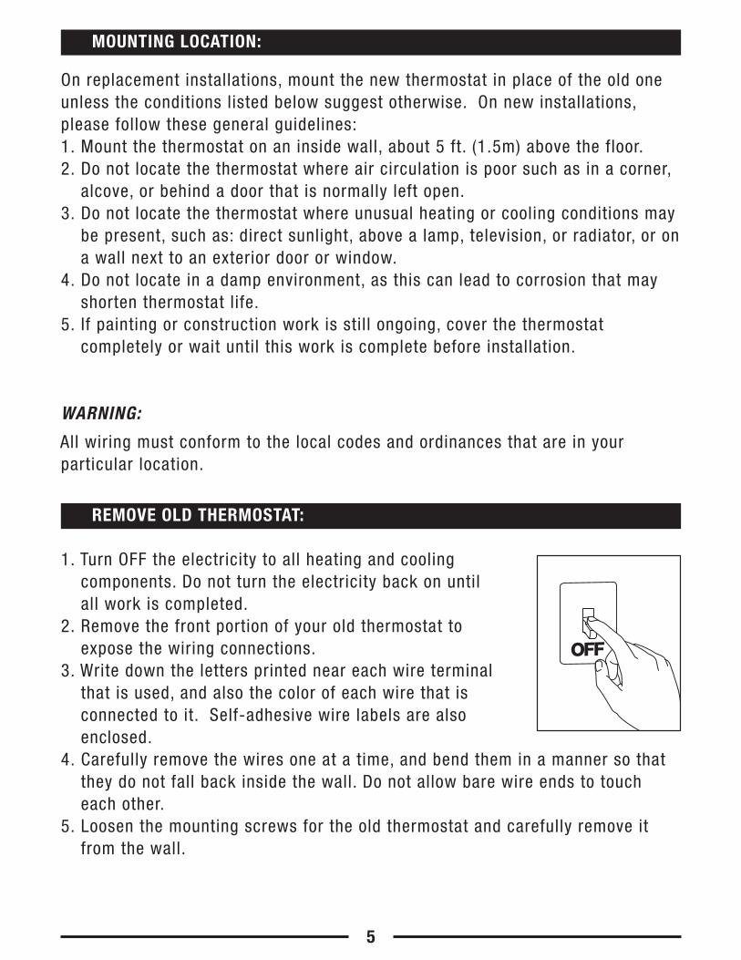
1. Turn OFF the electricity to all heating and coolingcomponents. Do not turn the electricity back on untilall work is completed.
2. Remove the front portion of your old thermostat toexpose the wiring connections.
3. Write down the letters printed near each wire terminalthat is used, and also the color of each wire that isconnected to it. Self-adhesive wire labels are alsoenclosed.
4. Carefully remove the wires one at a time, and bend them in a manner so thatthey do not fall back inside the wall. Do not allow bare wire ends to toucheach other.
5. Loosen the mounting screws for the old thermostat and carefully remove itfrom the wall.
REMOVE OLD THERMOSTAT:
MOUNTING LOCATION:
OFF
5
1. Strip wire insulation leaving only 3/8 in. (9.5mm) bare wire ends, and clean offany corrosion present.
2. Fill the wall opening with non-combustible insulation to prevent drafts fromaffecting the thermostat’s normal operation.
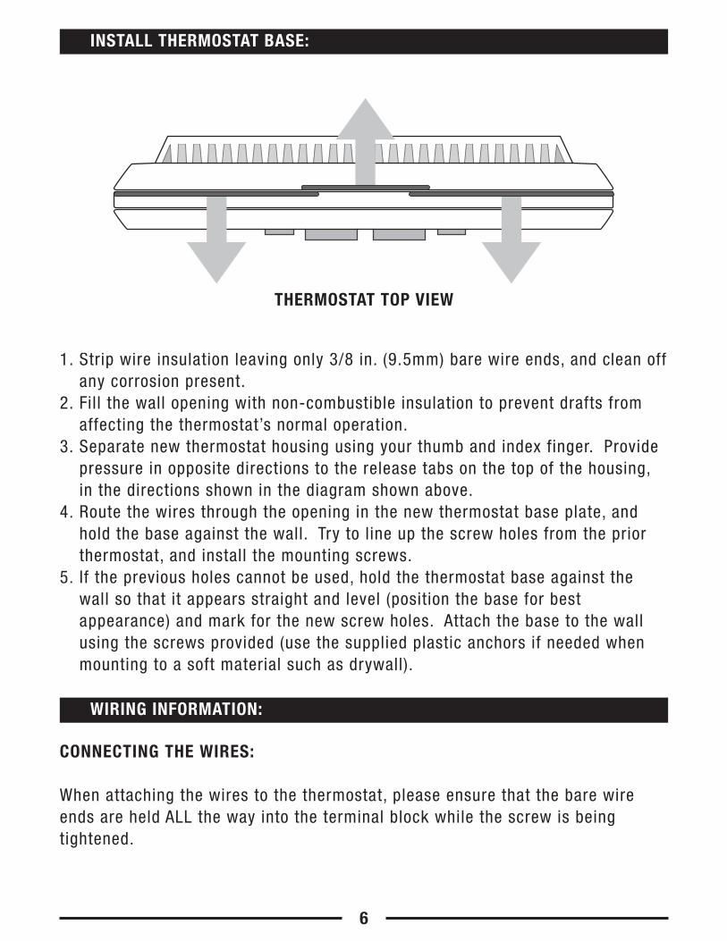
3. Separate new thermostat housing using your thumb and index finger. Providepressure in opposite directions to the release tabs on the top of the housing,in the directions shown in the diagram shown above.
4. Route the wires through the opening in the new thermostat base plate, andhold the base against the wall. Try to line up the screw holes from the priorthermostat, and install the mounting screws.
5. If the previous holes cannot be used, hold the thermostat base against thewall so that it appears straight and level (position the base for bestappearance) and mark for the new screw holes. Attach the base to the wallusing the screws provided (use the supplied plastic anchors if needed whenmounting to a soft material such as drywall).
CONNECTING THE WIRES:
When attaching the wires to the thermostat, please ensure that the bare wireends are held ALL the way into the terminal block while the screw is beingtightened.
WIRING INFORMATION:
6
INSTALL THERMOSTAT BASE:
THERMOSTAT TOP VIEW
WIRING DIAGRAM NOTES:
(Important, please read all notes before connecting wires)
• If the information provided in the following wiring diagrams does not clearlyrepresent or match your system, please refer to the “TECHNICAL ASSISTANCE”section of this manual, and contact us before removing any of your existingthermostat wiring.
• All of the dashed wires shown in the wiring diagrams are either optional, ortheir usage depends upon your specific system type or brand. For example:Diagram #1 shows the fan wire as optional. If your system does not have afan, than this terminal will not be used.
• Terminal letters shown in black represent typical wiring applications.Depending upon the brand of your specific system or thermostat, your terminalletters may not match exactly. Terminal letters shown in gray represent otherpossible wiring designations that you might see on your existing thermostatterminals.
• The optional “C” terminal is used for powering the thermostat by the 24-voltsystem, using the System Common wire. This can be used alone, or inaddition to installing batteries as a backup. NOTE: connecting the SystemCommon wire to the thermostat is not necessary for heating and cooling tofunction properly.
• If your old thermostat has both a “Y” and “C” wire both present, then “C” ismost likely a System Common wire.
• For Heat Pump systems, you will use either the “O” terminal or the “B”terminal on this thermostat, but not both. If your old thermostat has both an“O” and a “B” wire present, then “B” is likely a System Common wire and maybe connected to the “C” terminal. Connecting a System Common wire to thisthermostat’s “B” terminal may damage the thermostat, and also your heatingand cooling system.
• Some Heat Pump systems have a wire for AUX electric heat (usually W2), andalso a separate wire for Emergency electric heat (usually E). This thermostatuses the W2 terminal for both AUX and Emergency Heat. Tape off your “E”wire, and confirm that all components function without it.
• If replacing an old thermostat that has a mechanical clock, there may be twowires labeled as “C” for the clock power. Tape off these wires and do notconnect them to the “C” terminal of this thermostat.
7
8
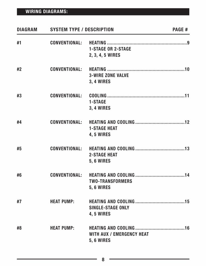
#1 CONVENTIONAL: HEATING ............................................................91-STAGE OR 2-STAGE2, 3, 4, 5 WIRES
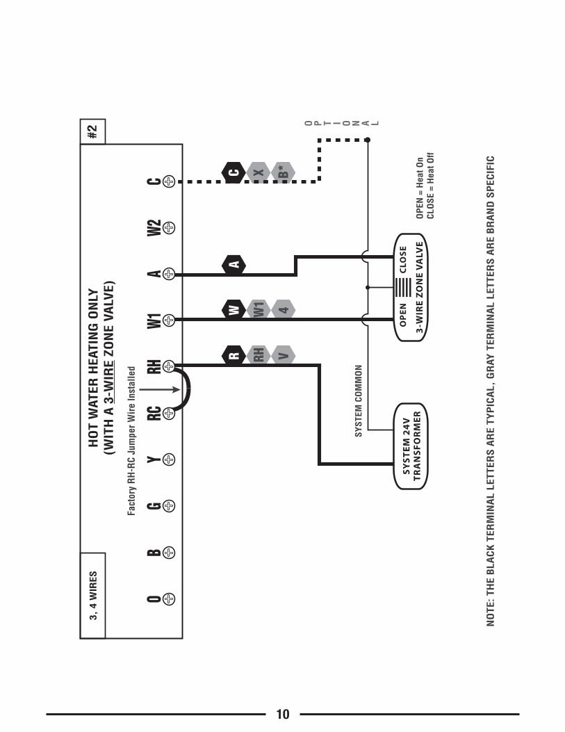
#2 CONVENTIONAL: HEATING ..........................................................103-WIRE ZONE VALVE3, 4 WIRES
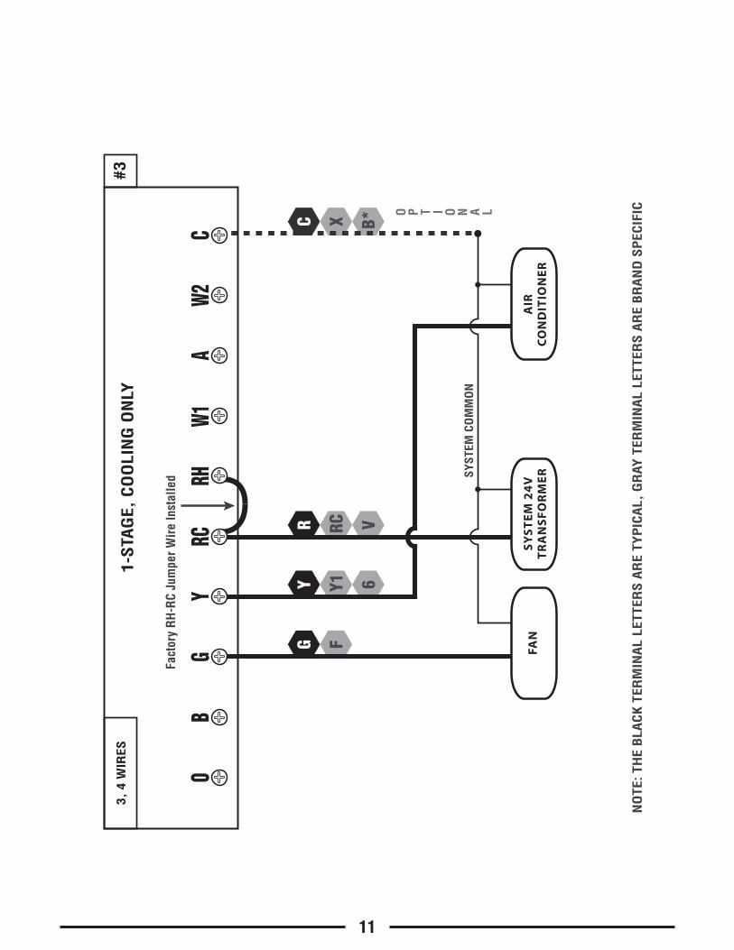
#3 CONVENTIONAL: COOLING ..........................................................111-STAGE3, 4 WIRES
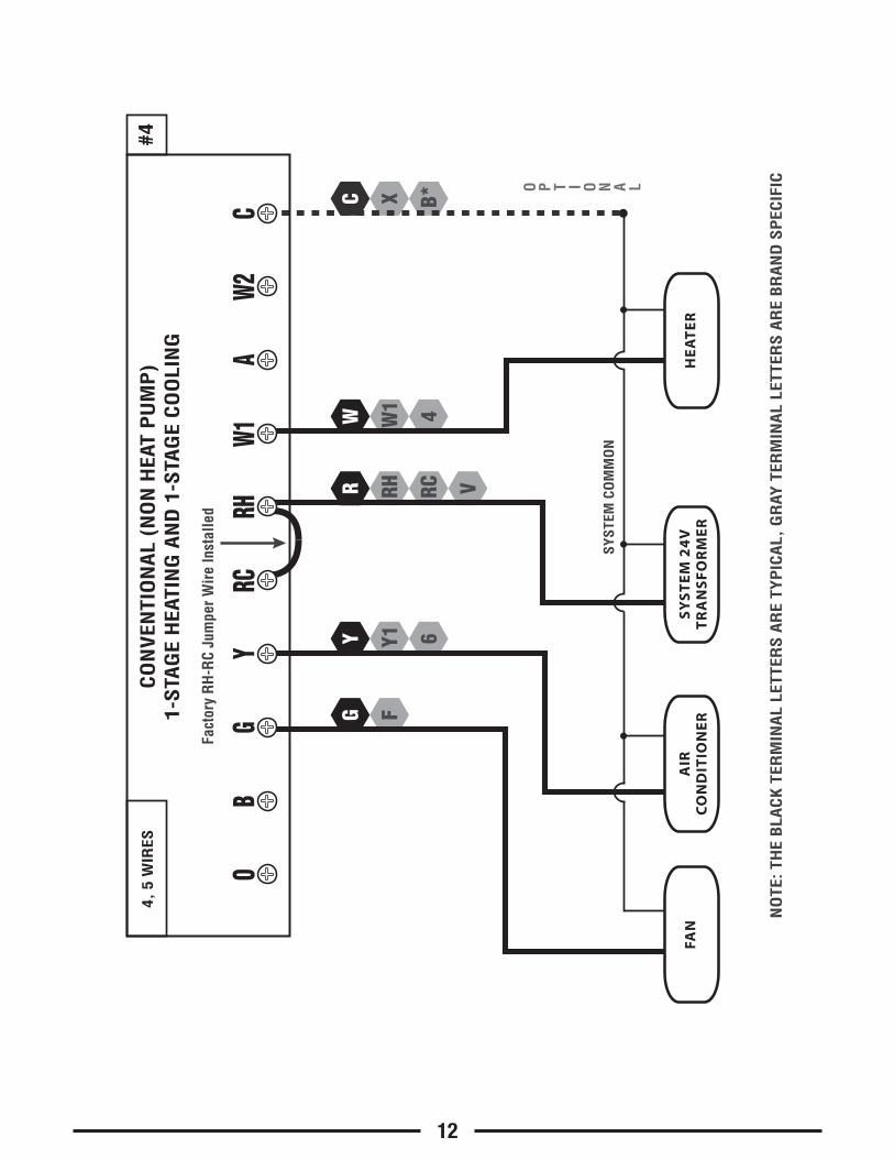
#4 CONVENTIONAL: HEATING AND COOLING .....................................121-STAGE HEAT4, 5 WIRES
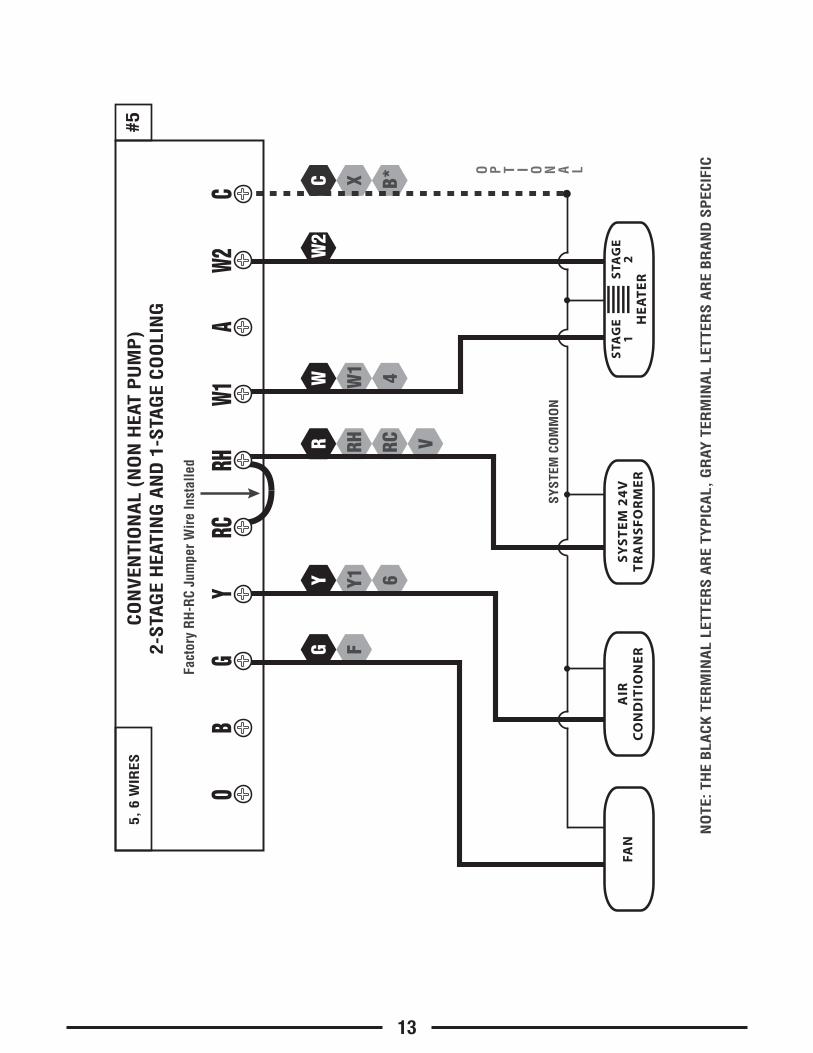
#5 CONVENTIONAL: HEATING AND COOLING .....................................132-STAGE HEAT5, 6 WIRES
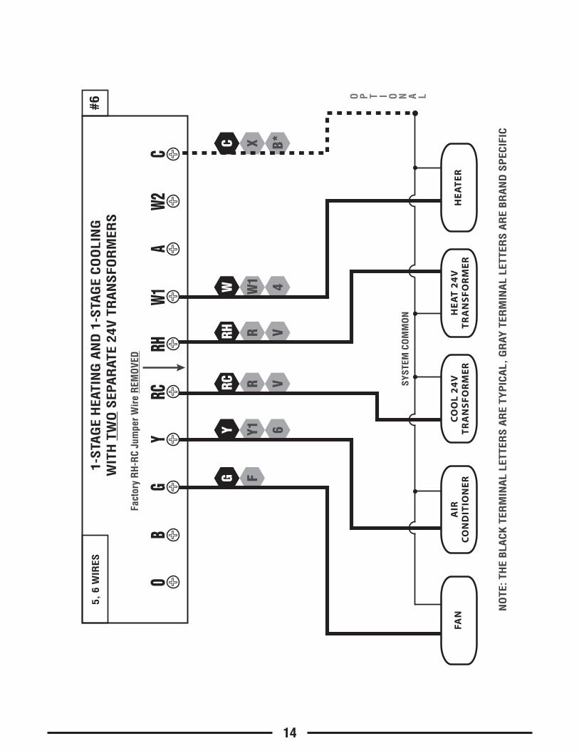
#6 CONVENTIONAL: HEATING AND COOLING .....................................14TWO-TRANSFORMERS5, 6 WIRES
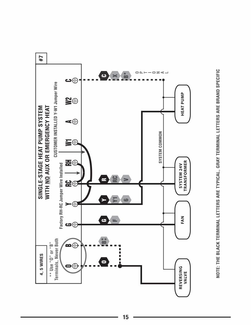
#7 HEAT PUMP: HEATING AND COOLING .....................................15SINGLE-STAGE ONLY4, 5 WIRES
#8 HEAT PUMP: HEATING AND COOLING .....................................16WITH AUX / EMERGENCY HEAT5, 6 WIRES
DIAGRAM SYSTEM TYPE / DESCRIPTION PAGE #
WIRING DIAGRAMS:

W1 4W
XFG
B*
W2
RH VR
W1A
W2O
BC
GY
RCRH
1-S
TAG
E O
R 2
-STA
GE,
HEA
TIN
G O
NLY
(IN
CLU
DIN
G M
ILLI
VO
LT)
(2-
WIR
E H
EAT
US
E “R
H”
& “
W1”
)
Fact
ory
RH
-RC
Jum
per W
ire
Inst
alle
d
#12,
3,
4, 5
WIR
ES
C
HE
AT
ER
STA
GE
1S
TAG
E2
FAN
SY
ST
EM
24
VT
RA
NS
FO
RM
ER
SYST
EM C
OM
MO
N
FAN
WIR
EM
AY N
OT
BEPR
ESEN
T IN
ALL
SYST
EMS
NO
TE: T
HE
BLA
CK
TER
MIN
AL
LETT
ERS
AR
E TY
PIC
AL,
GR
AY T
ERM
INA
L LE
TTER
S A
RE
BR
AN
D S
PEC
IFICO P T I O N A L
9
X B*C
RH VR
W1 4W
A
W1A
W2O
BC
GY
RCRH
HO
T W
ATER
HEA
TIN
G O
NLY
(WIT
H A
3-W
IRE
ZON
E VA
LVE)
Fact
ory
RH
-RC
Jum
per W
ire
Inst
alle
d
#23,
4 W
IRES
NO
TE: T
HE
BLA
CK
TER
MIN
AL
LETT
ERS
AR
E TY
PIC
AL,
GR
AY T
ERM
INA
L LE
TTER
S A
RE
BR
AN
D S
PEC
IFIC
SY
ST
EM
24
VT
RA
NS
FO
RM
ER
SYST
EM C
OM
MO
N
OPE
N =
Hea
t On
CLO
SE =
Hea
t Off
3-W
IRE
ZO
NE
VA
LVE
OP
EN
CLO
SE
O P T I O N A L
10
XFG
Y1 6Y
B*
RC VR
W1A
W2O
BC
GY
RCRH
1-S
TAG
E, C
OO
LIN
G O
NLY
Fact
ory
RH
-RC
Jum
per W
ire
Inst
alle
d
#3
C
FAN
SY
ST
EM
24
VT
RA
NS
FO
RM
ERSY
STEM
CO
MM
ON
3, 4
WIR
ES
NO
TE: T
HE
BLA
CK
TER
MIN
AL
LETT
ERS
AR
E TY
PIC
AL,
GR
AY T
ERM
INA
L LE
TTER
S A
RE
BR
AN
D S
PEC
IFICO P T I O N A L
AIR
CO
ND
ITIO
NE
R
11
RH RC VR
Y1 6Y
FG
XW
1 4W
B*
W1A
W2C
GO
BY
RCRH
CO
NV
ENTI
ON
AL
(NO
N H
EAT
PU
MP
)1-
STA
GE
HEA
TIN
G A
ND
1-S
TAG
E C
OO
LIN
G
Fact
ory
RH
-RC
Jum
per W
ire
Inst
alle
d
#4
C
FAN
SY
ST
EM
24
VT
RA
NS
FO
RM
ER
SYST
EM C
OM
MO
N
HE
AT
ER
AIR
CO
ND
ITIO
NE
R
4, 5
WIR
ES
NO
TE: T
HE
BLA
CK
TER
MIN
AL
LETT
ERS
AR
E TY
PIC
AL,
GR
AY T
ERM
INA
L LE
TTER
S A
RE
BR
AN
D S
PEC
IFICO P T I O N A L
12
W2
RH RC VR
Y1 6Y
FG
XW
1 4W
B*
W1A
W2C
GO
BY
RCRH
CO
NV
ENTI
ON
AL
(NO
N H
EAT
PU
MP
)2-
STA
GE
HEA
TIN
G A
ND
1-S
TAG
E C
OO
LIN
G
Fact
ory
RH
-RC
Jum
per W
ire
Inst
alle
d
#5
C
FAN
SY
ST
EM
24
VT
RA
NS
FO
RM
ER
SYST
EM C
OM
MO
N
AIR
CO
ND
ITIO
NE
R
5, 6
WIR
ES
NO
TE: T
HE
BLA
CK
TER
MIN
AL
LETT
ERS
AR
E TY
PIC
AL,
GR
AY T
ERM
INA
L LE
TTER
S A
RE
BR
AN
D S
PEC
IFICO P T I O N A L
HE
AT
ER
STA
GE
1S
TAG
E2
13
X B*C
R VRH
R VRC
Y1 6Y
FG
W1 4W
W1A
W2O
BC
GY
RCRH
1-S
TAG
E H
EATI
NG
AN
D 1
-STA
GE
CO
OLI
NG
WIT
H T
WO
SEP
AR
ATE
24V
TR
AN
SFO
RM
ERS
Fact
ory
RH
-RC
Jum
per W
ire
REM
OVE
D
#6
FAN
HE
AT
24
VT
RA
NS
FO
RM
ER
CO
OL
24
VT
RA
NS
FO
RM
ER
SYST
EM C
OM
MO
N
HE
AT
ER
AIR
CO
ND
ITIO
NE
R
5, 6
WIR
ES
NO
TE: T
HE
BLA
CK
TER
MIN
AL
LETT
ERS
AR
E TY
PIC
AL,
GR
AY T
ERM
INA
L LE
TTER
S A
RE
BR
AN
D S
PEC
IFIC
O P T I O N A L
14
O
XFG
Y1 6Y
B*
RC VR
W1A
W2O
BC
GY
RCRH
SIN
GLE
-STA
GE
HEA
T P
UM
P S
YS
TEM
WIT
H N
O A
UX
OR
EM
ERG
ENC
Y H
EAT
#7
C
FAN
SY
ST
EM
24
VT
RA
NS
FO
RM
ERSY
STEM
CO
MM
ON
4, 5
WIR
ES
NO
TE: T
HE
BLA
CK
TER
MIN
AL
LETT
ERS
AR
E TY
PIC
AL,
GR
AY T
ERM
INA
L LE
TTER
S A
RE
BR
AN
D S
PEC
IFICO P T I O N A L
HE
AT
PU
MP
RE
VE
RS
ING
VA
LVE
** U
se “
O”
or “
B”Te
rmin
als,
Nev
er B
oth
CUST
OM
ER IN
STAL
LED
Y-W
1 Ju
mpe
r Wir
eFa
ctor
y R
H-R
C Ju
mpe
r Wir
e In
stal
led
15
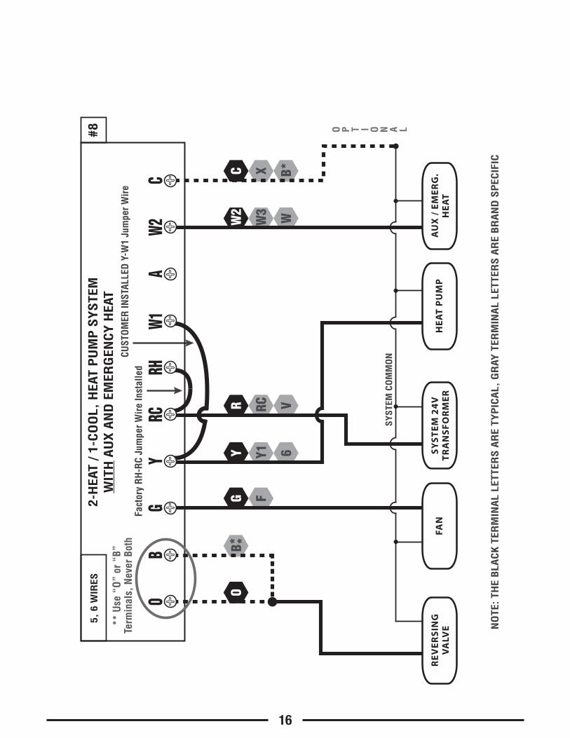
CUST
OM
ER IN
STAL
LED
Y-W
1 Ju
mpe
r Wir
e
X B*C
W3 WW2
O
FG
Y1 6Y
RC VR
W1A
W2O
BC
GY
RCRH
2-H
EAT
/ 1-
CO
OL,
HEA
T P
UM
P S
YS
TEM
WIT
H A
UX
AN
D E
MER
GEN
CY
HEA
T
Fact
ory
RH
-RC
Jum
per W
ire
Inst
alle
d
#8
FAN
SY
ST
EM
24
VT
RA
NS
FO
RM
ER
SYST
EM C
OM
MO
N
5, 6
WIR
ES
NO
TE: T
HE
BLA
CK
TER
MIN
AL
LETT
ERS
AR
E TY
PIC
AL,
GR
AY T
ERM
INA
L LE
TTER
S A
RE
BR
AN
D S
PEC
IFIC
HE
AT
PU
MP
RE
VE
RS
ING
VA
LVE
** U
se “
O”
or “
B”Te
rmin
als,
Nev
er B
oth
AU
X /
EM
ER
G.
HE
AT
O P T I O N A L
16
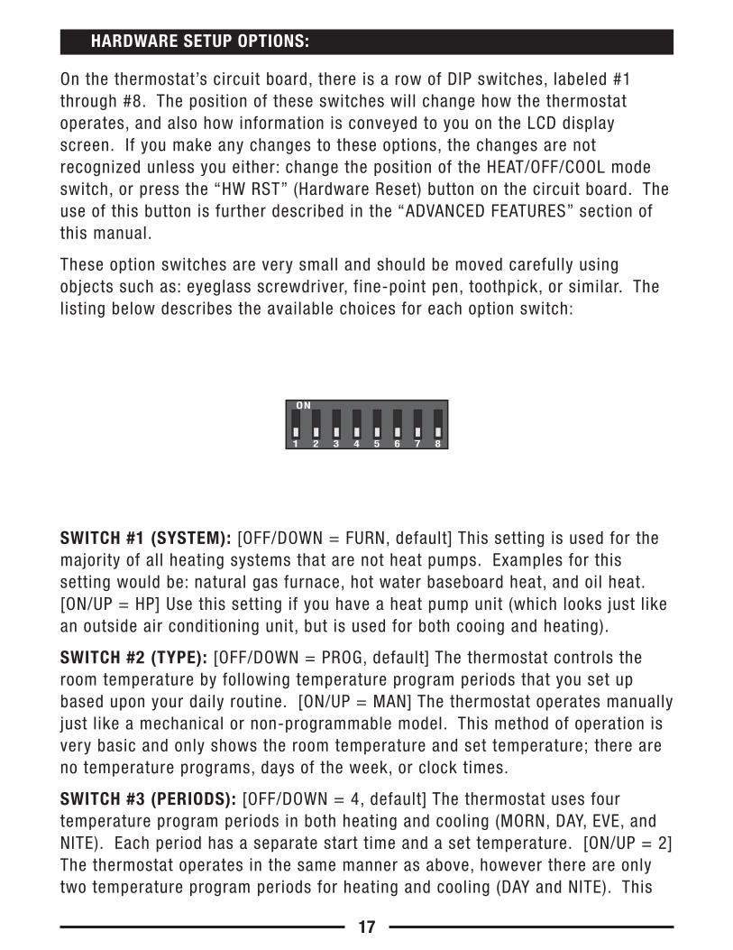
On the thermostat’s circuit board, there is a row of DIP switches, labeled #1through #8. The position of these switches will change how the thermostatoperates, and also how information is conveyed to you on the LCD displayscreen. If you make any changes to these options, the changes are notrecognized unless you either: change the position of the HEAT/OFF/COOL modeswitch, or press the “HW RST” (Hardware Reset) button on the circuit board. Theuse of this button is further described in the “ADVANCED FEATURES” section ofthis manual.
These option switches are very small and should be moved carefully usingobjects such as: eyeglass screwdriver, fine-point pen, toothpick, or similar. Thelisting below describes the available choices for each option switch:
SWITCH #1 (SYSTEM): [OFF/DOWN = FURN, default] This setting is used for themajority of all heating systems that are not heat pumps. Examples for thissetting would be: natural gas furnace, hot water baseboard heat, and oil heat.[ON/UP = HP] Use this setting if you have a heat pump unit (which looks just likean outside air conditioning unit, but is used for both cooing and heating).
SWITCH #2 (TYPE): [OFF/DOWN = PROG, default] The thermostat controls theroom temperature by following temperature program periods that you set upbased upon your daily routine. [ON/UP = MAN] The thermostat operates manuallyjust like a mechanical or non-programmable model. This method of operation isvery basic and only shows the room temperature and set temperature; there areno temperature programs, days of the week, or clock times.
SWITCH #3 (PERIODS): [OFF/DOWN = 4, default] The thermostat uses fourtemperature program periods in both heating and cooling (MORN, DAY, EVE, andNITE). Each period has a separate start time and a set temperature. [ON/UP = 2]The thermostat operates in the same manner as above, however there are onlytwo temperature program periods for heating and cooling (DAY and NITE). This
17
ON
1 2 3 4 5 6 7 8
HARDWARE SETUP OPTIONS:
may be more convenient if you are typically home during the day, and only needthe set temperature to be different while you are sleeping.
SWITCH #4 (SCALE): [OFF/DOWN = F, default] All temperature values aredisplayed using the Fahrenheit scale. [ON/UP = C] This setting displays alltemperature values using the Celsius scale.
SWITCH #5 (TIME): [OFF/DOWN = 12 HR, default] This setting displays the clocktimes and temperature program period start time values on the screen using USstandard AM and PM values. [ON/UP = 24 HR] This setting displays the clock andtemperature program period start time values on the screen using the 24 HRmilitary-time format (17:30 hours, 22:00 hours, without using AM/PM).
SWITCH #6 (DELAY): [OFF/DOWN = 5 MIN, default] This sets the minimum lengthof time that Heat or Cool must remain either On or Off, before it willautomatically switch to the alternate On or Off state. This internal delay preventsrapid cycling of your system and provides equipment protection particularly forcooling units. The 5-minute setting is fine for most applications. [ON/UP = 2MIN] If you feel that your system may need to cycle more frequently than thethermostat is allowing, then you may use the 2-minute setting.
SWITCH #7 (RECOVERY): [OFF/DOWN = DISABLE, default] The Early Recoveryfeature affects how the thermostat transitions from an energy saving setback(DAY and NITE) program period, to a comfort (MORN and EVE) program periodtemperature, when it is following the daily temperature programs. When this isdisabled, the thermostat makes a set temperature change at the beginning of anupcoming period's start time. [ON/UP = ENABLE] The Early Recovery feature willcalculate the capability of your system and turn on the heating or cooling earlyso that the temperature in your home reaches the desired set point as close aspossible to the start of the period. During the time that the thermostat isperforming a recovery, the word “RECOV.” will be shown in the display screen.
SWITCH #8 (BATTERY MONITOR): [OFF/DOWN = ON, default] This setting,regularly monitors the battery level, and shows “LOW BAT” on the screen if thebatteries need to be replaced. Use this setting at all times when batteries arepresent in the thermostat. [ON/UP = OFF] This setting only applies if you areNOT physically using batteries in the thermostat, and are powering thethermostat entirely from the system (“C” wire terminal).
18
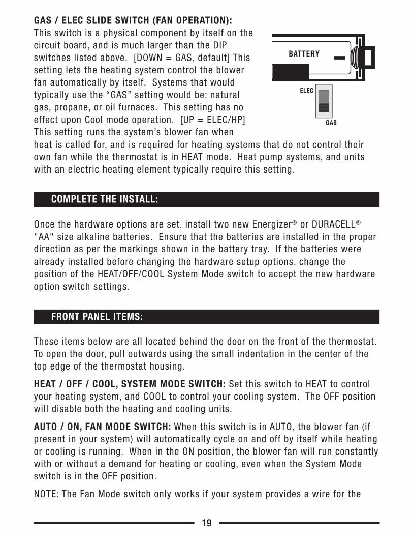
GAS / ELEC SLIDE SWITCH (FAN OPERATION):This switch is a physical component by itself on thecircuit board, and is much larger than the DIPswitches listed above. [DOWN = GAS, default] Thissetting lets the heating system control the blowerfan automatically by itself. Systems that wouldtypically use the “GAS” setting would be: naturalgas, propane, or oil furnaces. This setting has noeffect upon Cool mode operation. [UP = ELEC/HP]This setting runs the system’s blower fan whenheat is called for, and is required for heating systems that do not control theirown fan while the thermostat is in HEAT mode. Heat pump systems, and unitswith an electric heating element typically require this setting.
Once the hardware options are set, install two new Energizer® or DURACELL®
"AA" size alkaline batteries. Ensure that the batteries are installed in the properdirection as per the markings shown in the battery tray. If the batteries werealready installed before changing the hardware setup options, change theposition of the HEAT/OFF/COOL System Mode switch to accept the new hardwareoption switch settings.
These items below are all located behind the door on the front of the thermostat.To open the door, pull outwards using the small indentation in the center of thetop edge of the thermostat housing.
HEAT / OFF / COOL, SYSTEM MODE SWITCH: Set this switch to HEAT to controlyour heating system, and COOL to control your cooling system. The OFF positionwill disable both the heating and cooling units.
AUTO / ON, FAN MODE SWITCH: When this switch is in AUTO, the blower fan (ifpresent in your system) will automatically cycle on and off by itself while heatingor cooling is running. When in the ON position, the blower fan will run constantlywith or without a demand for heating or cooling, even when the System Modeswitch is in the OFF position.
NOTE: The Fan Mode switch only works if your system provides a wire for the
19
COMPLETE THE INSTALL:
FRONT PANEL ITEMS:
ELEC
GAS
BATTERY
thermostat’s “G” wire terminal, to control a blower fan. The Fan Mode switchhas no effect in systems that do not have a blower fan (such as a hot waterradiator system).
MULTI-FUNCTION, SET SLIDE SWITCH: This switch provides an easy way toquickly access the most commonly used thermostat settings. This switch has 4individual positions, and unless a specific setting is being adjusted, this switchshould always remain in the RUN position for the thermostat to control the roomtemperature. The other Set Slide switch positions are described in greater detailin the ADVANCED FEATURES section. NOTE: this switch is only operable when thethermostat is in “Programmable” mode. When the thermostat is used in“Manual” control mode, all 4 of the switch positions will act like the RUNposition, except the “AIR FILTER” position.
SETBACK BUTTON: This button activates and deactivates the SETBACK feature,which overrides the set temperature for an adjustable duration. This feature isdescribed in greater detail in the ADVANCED FEATURES section.
UP / DOWN BUTTONS: The UP and DOWN buttons are used to adjust any itemthat can be changed by the user. Examples are the set temperatures, clocktimes, and days of the week. In many cases, an item may be flashing if it cancurrently be adjusted.
HOLD BUTTON: This button activates and deactivates the manual TemperatureHold feature.
EMER BUTTON: When in Normal Run mode, the usage of this button variesdepending upon your specific system configuration. For heat pump systems,pressing this button enables your emergency heat function, which is described ingreater detail in the OPERATING INSTRUCTIONS section. For conventionalsystems, there is no such thing as emergency heat, so this button will have noeffect.
20
NEXT BUTTON: This button is mostly used while setting items such as softwareoptions, and temperature program periods. When there are several items on thescreen that can be changed, usually one of them is flashing indicating that it canbe adjusted. Pressing the NEXT button will cycle through which item is flashing.
SET DAY AND TIME: Place the Set Slide Switch into the DAY/TIME position. Withthe day flashing, press UP or DOWN to set the day of the week. Press NEXT andthe clock time will start flashing. Use UP or DOWN to set the time, making surethe AM/PM indication is correct. Holding the UP or DOWN buttons will make theclock digits scroll rapidly. Return the Set Slide switch to the RUN position whenfinished.
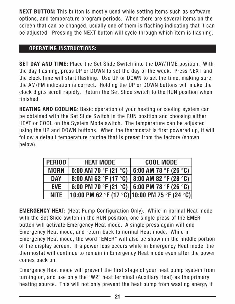
HEATING AND COOLING: Basic operation of your heating or cooling system canbe obtained with the Set Slide Switch in the RUN position and choosing eitherHEAT or COOL on the System Mode switch. The temperature can be adjustedusing the UP and DOWN buttons. When the thermostat is first powered up, it willfollow a default temperature routine that is preset from the factory (shownbelow).
EMERGENCY HEAT: (Heat Pump Configuration Only). While in normal Heat modewith the Set Slide switch in the RUN position, one single press of the EMERbutton will activate Emergency Heat mode. A single press again will endEmergency Heat mode, and return back to normal Heat mode. While inEmergency Heat mode, the word “EMER” will also be shown in the middle portionof the display screen. If a power loss occurs while in Emergency Heat mode, thethermostat will continue to remain in Emergency Heat mode even after the powercomes back on.
Emergency Heat mode will prevent the first stage of your heat pump system fromturning on, and use only the “W2” heat terminal (Auxiliary Heat) as the primaryheating source. This will not only prevent the heat pump from wasting energy if
21
PERIODMORNDAYEVENITE
HEAT MODE6:00 AM 70 °F (21 °C)8:00 AM 62 °F (17 °C)6:00 PM 70 °F (21 °C)10:00 PM 62 °F (17 °C)
COOL MODE6:00 AM 78 °F (26 °C)8:00 AM 82 °F (28 °C)6:00 PM 78 °F (26 °C)10:00 PM 75 °F (24 °C)
OPERATING INSTRUCTIONS:
outdoor temperatures are too low to support efficient operation, but it could alsoprevent damage to the heat pump if outside temperatures are below themanufacturer’s recommendations. As every heat pump has different operatingcharacteristics, you should refer to your heat pump literature to determine whento disable the heat pump and run in Emergency Heat mode.
LCD DISPLAY BACKLIGHT: The display screen is lighted to assist viewing atnighttime, or in locations with low light levels. A press of any button on the frontpanel will light the display for approximately 10 seconds. Any button pressesthat occur while the light is on will reset the 10-second timer, causing the screento remain illuminated for an additional 10 seconds.
TEMPERATURE OVERRIDE: While in Program RUN mode, the set temperature canbe temporarily changed by pressing UP or DOWN. The set temperature will returnto the programmed value stored in memory when the start time of the nextupcoming program period is reached (Morn, Day, Eve, Nite). While a TemporaryOverride is in effect, the word “OVERRIDE” will be shown in the display screen.An Override may be cancelled moving the mode switch to OFF, then back to HEATor COOL.
MINIMUM RUN TIME: The thermostat has a default internal time delay of 5minutes between load-on and load-off activations to prevent heating or coolingsystem damage, which can occur from very frequent cycling. If heating orcooling does not turn on right away with a manual change in set temperature,please wait at least 5 minutes and the system should resume normal operation.
TEMPERATURE HOLD: A Temperature Hold is used for maintaining a fixed settemperature. Once a Hold is initiated, the thermostat will maintain the settemperature indefinitely. A Hold may be used for days, weeks, or even months ata time, as long as the thermostat has adequate power. To enter Hold mode:press the HOLD button one time and the word “HOLD” will appear in the display.To cancel a Hold, press the HOLD button one more time. If a complete powerfailure occurs during a Temperature Hold, the thermostat will continue to remainin Hold mode even after the power comes back on. NOTE: If you plan to leavethe thermostat in Hold mode for an extended duration (unattended), it isadvisable to install new Energizer® or DURACELL® "AA" size alkaline batteriesprior to leaving to ensure reliable operation of your heating and cooling system.
STATIC NOTICE: This thermostat is protected against normal static electricdischarges, however to minimize the risk of damaging the unit in extremely dryweather, please touch a grounded metal object before touching your thermostat.
22
By default, this thermostat has 4 separate program periods for both Heat andCool mode, they are: MORN, DAY, EVE, and NITE. Each period ends at the starttime of the following period. The heat programs are set in HEAT mode, and thecool programs are set in COOL mode.
NOTE: If the thermostat is configured to use only 2 periods per day instead of 4(HARDWARE SETUP OPTIONS), the thermostat will only use the DAY and NITEperiods. The MORN and EVE periods will not be visible on the screen.
SET TEMPERATURE PROGRAMS: Move the Set Slide switch to the TEMP PROGposition. Programming will start with all 5 weekdays, Monday through Friday (allgrouped together). Use the UP/DOWN buttons to adjust the start time for theMORN period, then press the NEXT button to advance. Use the UP/DOWN buttonsto adjust the set temperature for the MORN period, then press the NEXT button toadvance. Now adjust the start time and set temperature for the DAY period,pressing the NEXT button after each to advance. Continue with these same stepsto adjust the start times and set temperatures for the EVE and NITE programperiods.
When the NITE period is finished for the weekdays, the thermostat will advanceforward to the Saturday program, with the MORN period start time flashing.Perform the same steps that you used for setting the weekday periods, pressingthe NEXT button to advance through each flashing value.
When the Saturday NITE period is finished, the thermostat will advance forwardto the Sunday program, with the MORN period start time flashing. Perform thesame steps that you used for setting the Saturday periods, pressing the NEXTbutton to advance through each flashing value. Return the Set Slide switch tothe RUN position when you are finished.
23
TEMPERATURE PROGRAMS:
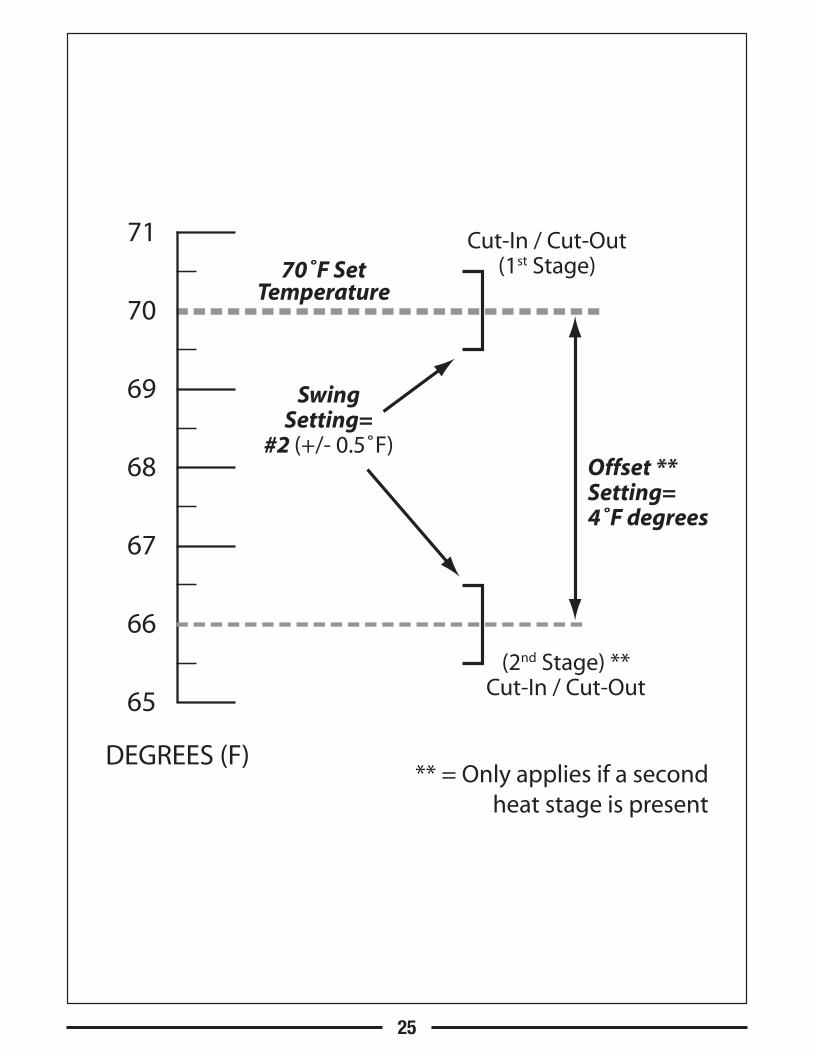
TEMPERATURE SWING AND OFFSET SETTING: A thermostat works by turningyour heating or cooling system on and off whenever the room temperature variesfrom the desired set-point temperature. The amount of this variation is calledthe swing. Generally your system should cycle on about 3 to 6 times per hour. Asmaller swing number makes the system cycle more frequently, so the roomtemperature is more precise and constant. A larger swing number will make thesystem remain on for a longer duration each time and decreases the number ofcycles per hour. There is only one Swing setting, and this determines the cut-inand cut-out points for both the first and second stages (if present), in both Heatmode and Cool mode.
NOTE: The Swing and Offset settings need to be performed in a timely manner, asthe thermostat will timeout and automatically exit these adjustment screens afterapproximately 10 seconds without a button press.
TO CHANGE THE SWING SETTING: Ensure that the System Mode switch is in theOFF position and the Set Slide switch is in the RUN position. Press and hold theHOLD button for at least 5 seconds. The words “SET” and “SWING” will appearon the screen, along with a single flashing digit. Use the UP/DOWN buttons tochange the number value between 1 and 9 (0.25F to 2.25F, in 0.25F degreeincrements). Number 1 is the default setting. Press the NEXT button to acceptthe swing setting and proceed to the OFFSET setting.
TO CHANGE THE OFFSET: After the Swing value has been accepted, the words“SET” and “OFFSET” will be shown on the screen, along with a flashing digit.This setting is shown as a number of degrees, and is similar in nature to theSwing however this only effects the operation of the second (auxiliary) heatingstage, if present. The setting range for Offset is from 0 to 9 degrees. When setto 0 degrees, the second heating stage is completely disabled while in regularHeat mode (Emergency Heat mode will still function for heat pumpconfigurations). An Offset value from 1 to 9 degrees will determine the numberof degrees from the set point that will be required for the second heating stageto turn on. This setting can be used to conserve energy in situations where thesecond heating stage is more costly to operate when compared to the first stage.
24
ADVANCED FEATURES:
70˚F SetTemperature
71
DEGREES (F)** = Only applies if a second
heat stage is present
70
69
68
67
66
65
SwingSetting=
#2 (+/- 0.5˚F)
Cut-In / Cut-Out(1st Stage)
(2nd Stage) **Cut-In / Cut-Out
Offset **Setting=4˚F degrees
25
TEMPERATURE CALIBRATION: The internal temperature sensor in this thermostatis accurately calibrated at the factory, and in most cases alterations to thissetting should not be needed. The Temperature Calibration feature allows you tomanually offset the measured temperature by as much as plus or minus 5°F(3°C) degrees from its original value. This feature can be useful to match orsynchronize this thermostat to another one or more, if multiple thermostats areused in the same home.
NOTE: The Temperature Calibration setting need to be performed in a timelymanner, as the thermostat will timeout and automatically exit the adjustmentscreen after approximately 10 seconds without a button press.
TO CHANGE THE TEMPERATURE CALIBRATION: Ensure that the System Modeswitch is in the OFF position and the Set Slide switch is in the RUN position.Press and hold both the UP and DOWN buttons together for at least 5 seconds.The words “SET” and “CAL” will appear on the screen, along with a singleflashing temperature digit. Use the UP/DOWN buttons to change the number ofdegrees of adjustment. 0° degrees is the default value, and means no correctionis being applied. Press the NEXT button to accept the setting.
SETBACK FEATURE: The setback feature is similar to both a TemperatureOverride and a Temperature Hold, in that both are used to maintain a fixed settemperature instead of following a programmed daily routine. A Setback can beconsidered the same as a Temperature Override, which can last for a longerduration that you can adjust from 1-12 hours, or 1-30 days. By default, when aSetback is activated in Heat mode, the set temperature used will be 5F (3C)degrees lower than the current set temp. For Cool mode, the set temperatureused will be 5F (3C) degrees higher than the current set temp.
TO START A SETBACK: Ensure that the System Mode switch is in either the Heator Cool position, and that the Set Slider is in the RUN position. Press and holdthe SETBACK button for at least 2 seconds. The screen will change and show thewords “HOURS LEFT” and “OVERRIDE”, along with two digits. Use the UP/DOWNbuttons to set the duration for how long you would like to maintain a fixed settemperature (from 1 to 12 hours). If you would like to set the duration for longerthan 12 hours, keep pressing the UP button. The display will change from“HOURS LEFT” to “DAYS LEFT”, with an available duration of 1 to 30 days. Onceyour desired Setback duration is shown on the screen, you can either wait for thescreen to advance forward on its own, or press the NEXT button (behind the door)one time to jump ahead rapidly. Now use the UP/DOWN buttons to select your
26
desired set temperature that will be used for the Setback duration. Just like theprevious step, you can either wait for the screen to advance on its own, or pressthe NEXT button to advance and return to the Normal Run screen.
TO CANCEL A SETBACK: While in the Normal Run screen, press and hold theSETBACK button for at least 2 seconds. The word “OVERRIDE” will disappearfrom the screen and the Setback will be cancelled. Moving the System Modeswitch or Set Slide switch, will also cancel a Setback.
TEMPERATURE LIMIT STOPS: There are two independent set temperature limitstops: a maximum heat set temperature, and a minimum cool set temperature.These stops do not prevent a user from performing normal actions likeTemperature Override or Hold. The Heat Limit Stop prevents the set temperaturefrom being adjusted higher than the heat limit setting. The Cool Limit Stopprevents the set temperature from being adjusted lower than the cool limitsetting. Each of these temperature stops is user adjustable in one-degreeincrements, and these settings are protected by a selectable 2-digit code toprevent unauthorized tampering. By default, this 2-digit code is “00”, and thetemperature stops can be used as-is with this code.
NOTE: The Temperature Limit Stop settings need to be performed in a timelymanner, as the thermostat will timeout and automatically exit the setting screensafter approximately 10 seconds without a button press.
TO SET THE HEAT LIMIT STOP: Place the System Mode switch in the OFF position,and the Set Slide switch in the RUN position. Press and hold the UP button whilesliding the System Mode switch from OFF to HEAT. The words “TEMP STOP” and“LOCK CODE” will appear on the screen, along with two digits. Use the UP/DOWNbuttons to select the proper code to access the heat limit setting. Press theNEXT button to accept the setting. If the code you tried was not correct, thethermostat will exit and return to the Normal Run screen with no changes made.If the entered code is correct, the screen will add the word “SET” and display thecurrent heat set temperature limit. Use the UP/DOWN buttons to adjust themaximum heat set temperature value. Press the NEXT button to accept thesetting and return to the Normal Run screen in heat mode.
TO SET THE COOL LIMIT STOP: Place the System Mode switch in the OFF position,and the Set Slide switch in the RUN position. Press and hold the DOWN buttonwhile sliding the System Mode switch from OFF to COOL. The words “TEMPSTOP” and “LOCK CODE” will appear on the screen, along with two digits. Use
27
the UP/DOWN buttons to select the proper code to access the cool limit setting.Press the NEXT button to accept the setting. If the code you tried was notcorrect, the thermostat will exit and return to the Normal Run screen with nochanges made. If the entered code is correct, the screen will add the word “SET”and display the current cool set temperature limit. Use the UP/DOWN buttons toadjust the minimum cool set temperature value. Press the NEXT button to acceptthe setting and return to the Normal Run screen in cool mode.
TO CHANGE THE TEMPERATURE STOP LOCK CODE: Place the System Mode switchin the OFF position, and the Set Slide switch in the RUN position. Press and holdthe NEXT button for at least 5 seconds. The words “TEMP STOP” and “LOCKCODE” will appear on the screen, along with two digits. Use the UP/DOWNbuttons to enter the current code (“00” by default) and press the NEXT buttonone time. The word “SET” will now be displayed. Use the UP/DOWN buttons tochoose a new 2-digit code between “00” and “99”. Press the NEXT button toaccept the setting. The screen will flash briefly to confirm the code change, andreturn to the Normal Run screen in Off mode.
IF YOU FORGET YOUR TEMPERATURE STOP CODE: The code can be reset to thefactory default “00” by performing the following steps. Place the System Modeswitch in the OFF position, and the Set Slide switch in the RUN position. Pressand hold the NEXT and HOLD buttons together for at least 10 seconds. Thescreen will start flashing, and display words “SET”, “TEMP STOP” and “LOCKCODE”, along with the new code of “00”. After a couple seconds, the screen willautomatically return to the Normal Run screen in Off mode.
KEYPAD LOCKOUT: You can lock the front panel buttons to prevent unauthorizedtampering of your thermostat settings.
NOTE: These keypad lock instructions need to be performed in a timely manner.The 4-button sequence which locks the thermostat must be entered within a 10-second timeframe, or the keypad lockout sequence will have to be entered againfrom the beginning.
TO LOCK THE KEYPAD: Start with the System Mode switch in either the HEAT orCOOL positions, and the Set Slide switch in the RUN position. Perform a singlepress of each button, in the following sequence: NEXT, NEXT, NEXT, HOLD.
TO UNLOCK THE KEYPAD: Start with the System Mode switch in either the HEATor COOL positions, and the Set Slide switch in the RUN position. Perform a singlepress of each button, in the following sequence: NEXT, NEXT, NEXT, HOLD. Thepadlock should no longer be present, with the thermostat now unlocked. If thepadlock is still on the screen, please try to enter the 4-button sequence again.
28
GRAPHICAL AIR FILTER MONITOR: In most systems that use a blower fan and airducts, there is an air filter that is either replaceable or requires cleaning. Thefilter is usually located in the air handler, where the blower fan is. Thisthermostat feature assists you with keeping track of proper maintenance and/orperiodic replacement intervals for your system’s filter.
The Graphical Filter Monitor displays a visual bar graph in the center of thescreen, which shows the amount of air filter life remaining (in % percent), sincethe last time the air filter timer has been reset. Each dot in the filter bar graphequals 10 percent (example: 4 dots shown means 40 percent filter liferemaining). This feature is for information purposes only, and does not affect theoperation of your heating or cooling equipment, or the thermostat. When thefilter usage duration has completly expired, the vertical filter bar graph will beempty, and the word “FILTER” will flash on the screen.
TO SET THE AIR FILTER DURATION: Move the Set Slide switch to the “AIR FILTER”position. The words “SET DAYS” will be shown on the screen, along with theword “FILTER” and 2-3 characters at the top right corner of the display. Presseither of the UP/DOWN buttons to select the desired filter duration (in days) fromthe following choices: OFF, 30, 60, 90, 120, 180, or 365. If the filter durationvalue is set to “OFF”, then the Air Filter Monitor will be completely disabled.Return the Set Slide switch to the RUN position when you are finished.
TO RESET THE FILTER USAGE COUNTER: Move the Set Slide switch to the “AIRFILTER” position. The three small digits at the bottom of the screen tell you thequantity of filter days remaining. Pressing the NEXT button will toggle thedisplay between showing the days remaining as a number, or a graphicalprecentage remaining using the vertical bar graph. Press both the UP and DOWNbuttons together at the same time, and the usage counter will return to thebeginning of the value that it originally started counting from. Refer to theprevious paragraph, should you wish to change the starting value for the filtermonitor. Return the Set Slide switch to the RUN position when you are finished.
29
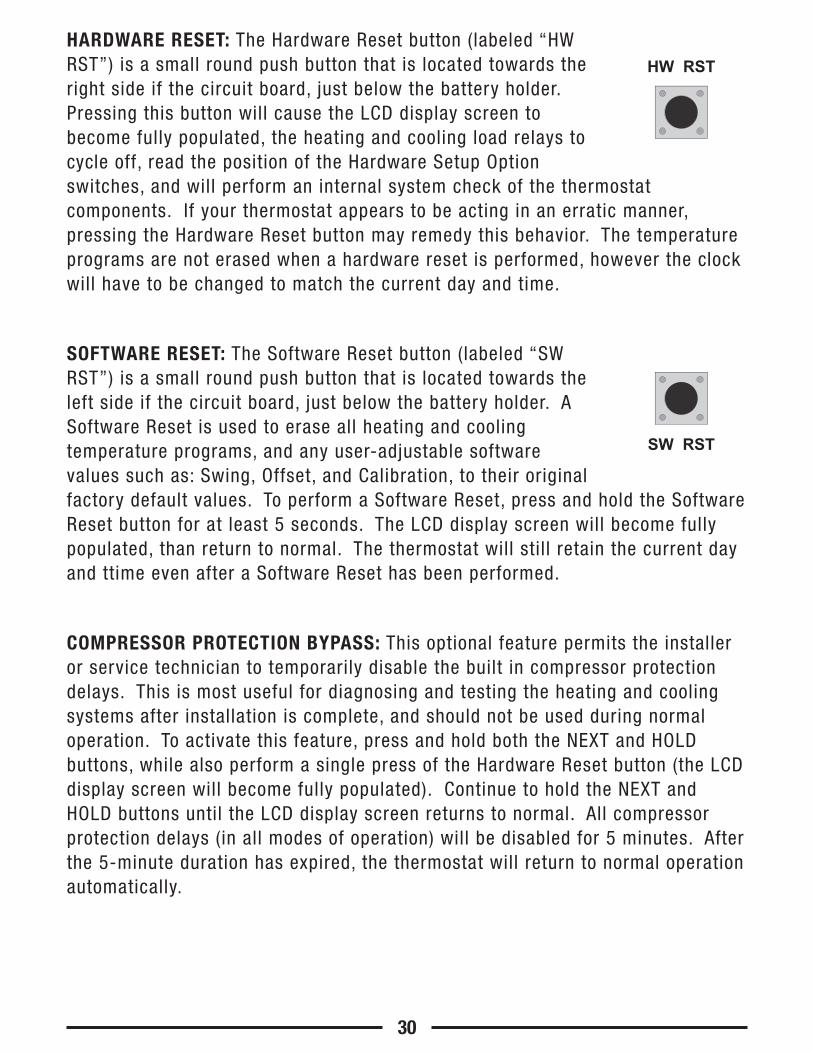
HARDWARE RESET: The Hardware Reset button (labeled “HWRST”) is a small round push button that is located towards theright side if the circuit board, just below the battery holder.Pressing this button will cause the LCD display screen tobecome fully populated, the heating and cooling load relays tocycle off, read the position of the Hardware Setup Optionswitches, and will perform an internal system check of the thermostatcomponents. If your thermostat appears to be acting in an erratic manner,pressing the Hardware Reset button may remedy this behavior. The temperatureprograms are not erased when a hardware reset is performed, however the clockwill have to be changed to match the current day and time.
SOFTWARE RESET: The Software Reset button (labeled “SWRST”) is a small round push button that is located towards theleft side if the circuit board, just below the battery holder. ASoftware Reset is used to erase all heating and coolingtemperature programs, and any user-adjustable softwarevalues such as: Swing, Offset, and Calibration, to their originalfactory default values. To perform a Software Reset, press and hold the SoftwareReset button for at least 5 seconds. The LCD display screen will become fullypopulated, than return to normal. The thermostat will still retain the current dayand ttime even after a Software Reset has been performed.
COMPRESSOR PROTECTION BYPASS: This optional feature permits the installeror service technician to temporarily disable the built in compressor protectiondelays. This is most useful for diagnosing and testing the heating and coolingsystems after installation is complete, and should not be used during normaloperation. To activate this feature, press and hold both the NEXT and HOLDbuttons, while also perform a single press of the Hardware Reset button (the LCDdisplay screen will become fully populated). Continue to hold the NEXT andHOLD buttons until the LCD display screen returns to normal. All compressorprotection delays (in all modes of operation) will be disabled for 5 minutes. Afterthe 5-minute duration has expired, the thermostat will return to normal operationautomatically.
30
HW RST
SW RST
This thermostat is powered by two “AA” Alkaline batteries. The batteries shouldbe replaced AT LEAST once per year to ensure reliable operation (or sooner, if the“LOW BATT” icon appears at the top of the display screen). The batteries arelocated on the back of the thermostat, at the top of the circuit board. The frontportion of the thermostat can be removed from the back half by pulling straightoutwards on the top and bottom of the thermostat housing, at the largeindentations that are present in the center of the top and bottom edges.
When installing new batteries, we recommend using only brand new Energizer®
or DURACELL®, “AA” size alkaline batteries. Please observe the polaritymarkings shown in the battery compartment to ensure proper installation. Whenfinished, line up the front of the thermostat to the base, and firmly press togetherto securely latch the front and back halves together properly.
If you have any problems installing or using this thermostat, please carefully andthoroughly review the instruction manual. If you require assistance, pleasecontact our Technical Assistance department at 856-234-8803 during regularbusiness hours between 8:00AM and 4:30PM Eastern Standard Time, Mondaythrough Friday. You can also receive technical assistance online anytime day ornight at http://www.luxproducts.com. Our website offers you troubleshootingguides, answers to the most common technical questions, and also permits youto email your questions to our technical support staff at your convenience.
31
BATTERY REPLACEMENT:
TECHNICAL ASSISTANCE:
If this unit fails because of defects in materials or workmanship within threeyears of the date of original purchase, LUX will, at its option, repair or replace it.This warranty does not cover damage by accident, misuse, or failure to followinstallation instructions. Implied warranties are limited in duration to three yearsfrom the date of original purchase. Some states do not allow limitations on howlong an implied warranty lasts, so the above limitation may not apply to you.Please return malfunctioning or defective units to the location from which thepurchase was made, along with proof of purchase. Please refer to “TECHNICALASSISTANCE” before returning thermostat. Purchaser assumes all risks andliability for incidental and consequential damage resulting from installation anduse of this unit. Some states do not allow the exclusion of incidental orconsequential damages, so the above exclusion may not apply to you. Thiswarranty gives you specific legal rights and you may also have other rights,which vary from state to state. Applicable in the U.S.A. and Canada only.
Mercury is considered to be a hazardous material. If this product is replacing athermostat that contains mercury in a sealed tube, contact your local wastemanagement authority for instructions regarding recycling and proper disposal.It may be unlawful in your state to place it in the trash.
32
LIMITED WARRANTY:
MERCURY WARNING AND RECYCLING NOTICE:
Philadelphia, PA 19912 www.luxproducts.com
856-234-7905
33
SETBACK HOLD
74F̊72F̊
5:36P
HEAT
TUDAY
SET
FAN
40%LEFTFILTER