Embed Size (px)
Citation preview

CONSTRUCTION STANDARDS GUIDELINES
Revised Jan-15 A/E Deliverables-2.02
TXST BIM-FM Requirements
Table of Contents
E.0 – Section 0 – Executive Summary
E.1 – Section 1 – Strategy and Objectives
E.2 – Section 2 – BIM Execution Plan
Exhibit 2.A – Sample Project Schedule
Exhibit 2.B – Close-Out Procedures
E.3 – Section 3 – FM Data Requirements
Exhibit 3.A – Responsibility Matrix
Exhibit 3.B – Facilities Data Integrator
Exhibit 3.C – Asset Type Matrix
Exhibit 3.D – FM Model Criteria

CONSTRUCTION STANDARDS GUIDELINES
Revised Jan-15 A/E Deliverables-2.02
E.0 – Section 0 - Executive Summary
Building Information Modeling (BIM) and
Facilities Management (FM) Data Requirements
Section 1 – Strategy and Objectives
Knowing the strategy and objectives of Texas State University (TXST) in Building Information
Management for Facilities Management (BIM for FM) is important for all project delivery teams (AEC
+ CxA) in order to satisfy the expectations and project requirements. The
strategy and objectives section states that the BIM for FM process and documentation was
undertaken by TXST in order to provide direction and to equip project teams for facilities
management data specification, collection, validation, and ultimately handover to TXST. Handover
deliverables shall be in a digital format and support operational objectives and efficiencies, such as
import to the asset management (CMMS - Computerized Maintenance Management System) system
AiM by AssetWorks.
Section 2 - BIM Execution Plan (BEP)
Developing and communicating a clear plan for carrying out BIM for FM is necessary for each project
team. The BIM Execution Plan (also referred to as a BEP) section provides an outline and framework
for planning how BIM for FM is to be accomplished at the project level. The overall intent is to allow
and require project delivery team members to communicate to TXST how they intend to meet the
BIM for FM requirements. Each member of the AEC team shall submit a plan per the stated
requirements in this section. The Facilities Data Integrator (FDI) receives each plan and reviews it
according to the contracted section requirements for that team member. This plan outlines items
such as: company roles, contact information, AEC team collaboration procedures, information
exchange schedules, quality control procedures, and others. Submitted execution plans enable the
Facilities Data Integrator (FDI), an agent of the owner (TXST), the ability to better guide and manage
teams to accomplish BIM for FM deliverables. The BEP allows teams to demonstrate how they will
comply with the prescriptive requirements as well as the performance based requirements. This
leaves room for project delivery teams to impose their own means and methods where prescriptive
requirements do not exist.
Section 3 - FM Data Criteria
The FM Data Criteria is the largest section of the BIM for FM Requirements documents. It is a detailed
specification and guide to understanding how project information shall be organized and delivered
to Texas State. This is the most prescriptive part of the BIM for FM process due to the specific and
structured data requirements for TXST’s configuration of AiM. This section outlines what data is to
be collected (i.e., what do we need), in what format (i.e., how do we need it delivered), division of
responsibility (i.e., who is to collect specific information), and deliverable schedules (i.e., when are

CONSTRUCTION STANDARDS GUIDELINES
Revised Jan-15 A/E Deliverables-2.02
the milestone deliverables over the project’s duration). This level of detail is required in order to
properly communicate and contract these requirements with the project delivery team members in
each standalone contract with the owner (i.e., AE, CM, CxA, others). In the absence of this level of
detail, confusion will be present and the process for BIM for FM will break down. This section
introduces a role called the Facilities Data Integrator (FDI) to the project delivery team who is chosen
by the owner to manage and ensure correct execution of BIM for FM data requirements and process
across the entire project delivery process. This section references attachments and specific Texas
State University roles for providing the latest version of the San Marcos facilities-specific data to be
incorporated into projects. Requirements for other campuses will differ for many reasons such as
the CMMS platform being employed by the campus, the data configurations for the CMMS, and the
content valued by the owner at that campus to name a few.

CONSTRUCTION STANDARDS GUIDELINES
Revised Jan-15 A/E Deliverables-2.02
E.1 - Section 1: Strategy and Objectives
Explanation of the BIM Strategy and Objectives
Texas State University (TXST) desires to use technology to improve construction projects and the
way they are handed over, keeping in mind operational objectives and efficiency. The strategy and
objectives of TXST in Building Information Modeling for Facilities Management (BIM for FM) is
important for all project delivery teams (AEC + CxA) in order to satisfy expectations and project
requirements. This section describes the reasoning behind BIM for FM process and documentation
was undertaken by TXST, and explains the intent to provide direction and to equip project teams for
facilities management data specification, collection, validation, and ultimately handover to TXST.
Handover deliverables shall be in a digital format and support operational objectives and efficiencies,
such as import to the asset management (CMMS - Computerized Maintenance Management System)
system using AiM by AssetWorks. Through the establishment of BIM for FM requirements, TXST will
obtain consistent and useful handover deliverables (digitally formatted) that support operations and
maintenance for many years to come. TXST’s intent is to facilitate and produce a repeatable process
at the San Marcos campus that can be employed on capital projects of various sizes.
The intent of this document is not to add unreasonable scope upon individual project team members,
but rather to provide a method and format for capturing useful project information that is already
being managed throughout the planning, design, construction, and commissioning phases. In some
cases, project team members will realize efficiencies by following these guidelines and having a
consistent project repository of facility data and associated documents. For other team members
that already use a thorough system for tracking project spaces, equipment, and documents, this
guideline will have little impact upon their current project workflows other than to specify the
owner’s requirements. By TXST investing in the development of this process, they will be able to
contract for these requirements in the course of the normal project delivery process, reduce change
orders, reduce rework, and allow project team members the opportunity to align their project
delivery processes and data management processes in advance of the performance of work. This
alignment is intended to eliminate rework situations and streamline the project delivery process for
digital data and documents for handover and integration by the Facilities Data Integrator (FDI) into
the owner’s operations and maintenance systems, namely AiM by AssetWorks.
TXST requires BIM to be used in a way that supports evolving and advancing operational and
maintenance workflows. Some specific BIM uses that the project team will be required to support
include but are not limited to: 1) record set 3D design model, 2) as-built/as-coordinated 3D trade
models, 3) Federated/combined trade model (in Navisworks NWD format), and 4) FM data set (in
COBie format) with associated documents to be imported to AiM by the Facilities Data Integrator
(FDI). The process established and confirmed by TXST does not require each project delivery team
member to be a 3D modeling subject matter expert or a COBie subject matter expert. Instead, the
project team members are required to provide elements of the facilities management data set
requirements over the life of the project in an open-standard format or in a manner that enables the

CONSTRUCTION STANDARDS GUIDELINES
Revised Jan-15 A/E Deliverables-2.02
Facilities Data Integrator (FDI) to extract the same information using industry standard tools and
software. These project details will be documented and confirmed by the approval of the BIM
Execution Plan (BEP) elements for each team member. BEP revisions may be required as team
members are added and as the overall plan evolves for the project team members. One of the FM
Data Integrator’s roles is to manage the overall BIM-FM Data process and oversee the compilation
(i.e., integration) of the FM Data while ensuring that configuration control is maintained for revisions
and changes over the lifecycle of the project. Thus, team members are expected to provide the same
type of project information they normally produce for use at specific points in the project lifecycle.
These are outlined along with the specific details of the role of FM Data Integrator in other sections
of the specifications. The BIM Execution Plan (BEP) will outline and document the project specific
processes to be employed and will provide a mechanism for owner review and approval of the FM
Data process via submittals for review and approval by the FDI. In this manner, additional services
are not expected from the project delivery team members because TXST is not asking for new
deliverables but rather, the same information in a modified format in advance of contracting and
work production to eliminate the occurrence of rework.
Description of Existing Infrastructure and other Operational Interfaces
TXST currently uses AiM by AssetWorks as its computerized maintenance management system
(CMMS). AiM supports the import of COBie (Construction Operations Building Information
Exchange) files, which is an industry recognized open standard data format. COBie is one “tool” that
is used in this process to organize and format the FM Data for use. The data structure (i.e., Asset
Groups) from AiM will help guide the assembly of COBie data at TXST. These data structure rules
have guided and informed the development of these requirements, and when followed correctly, will
ensure project teams have built the COBie data-set in a manner that is consistent with TXST CMMS
requirements and data structures.
TXST anticipates using 3D models as a tool in facilities management. By requiring project teams to
coordinate and share building models, allowance is made for immediate and future needs of the
university. Therefore, all 3D Facilities Models (i.e., models from the AE (design intent) and the CM
(as-built)) shall be provided in an acceptable format (see the FM data specifications) and not in any
other proprietary or subscription based software. Additional requirements can be found in the FM
data specifications.
As the construction industry and technology advances, TXST will make incremental changes to the
BIM for FM requirements over time. The current specifications represent the first generation of FM
Data specifications and changes are expected to be accepted and processed that will integrate future
technologies and workflow changes over time. However, these must be evaluated by TXST for
adoption from the industry and integrated into the project delivery strategy and handover
requirements in light of how TXST does FM work and how they want to receive and process project
information (data), documents, and models.

CONSTRUCTION STANDARDS GUIDELINES
Revised Jan-15 A/E Deliverables-2.02
Explanation of TXST Expectations
The FM data specifications developed for and applied to this project are an evolving guideline for
capturing BIM data at TXST. However, a specific set of requirements does apply to this contract per
the identified Exhibit. With each new building, this specification may require the attention of an
Facilities Data Integrator (FDI) to ensure current requirements are appropriate and/or are updated
for additional scope that was unforeseen at the writing of the current publication. This updating
process will continue to “build-out” and enhance the overall FM Data specifications in a way that
creates a more robust specification based upon project scopes and building/project types at TXST.
The first generation FM Data specifications have been formulated to capture as much institutional
information as possible based upon past FM Data projects conducted. It should be noted that each
owner has a varying array of interests and requirements that are driven by their perception of the
value to the FM process. Thus, these requirements are likely to be modified over time as more
operating experience is gained in the use of FM Data and associated documents.
The FM Data Integrator shall also assess each project teams’ ability to perform the scope of the BIM
and FM data requirements and provide specific recommendations for implementing requirements
on a project by project basis. The role and responsibility of FM Data Integrator is outlined in other
sections of this guide. However, the general responsibility is to manage the BIM process and the FM
Data on projects and to ensure the correct execution of these BIM for FM Data guidelines. The role
of the FM Data Integrator can be performed by different parties within the project delivery team
during construction or within TXST (i.e., internal direct staff or a third party consultant) throughout
a project’s life cycle.
TXST expects that all large scale projects will use the current BIM for FM requirements and produce
an FM data-set for import into the CMMS. However, the Director of Facilities Management will
determine expectations in regard to these requirements on projects under five million ($5M) dollars.
Project team members will each be expected to contribute to the project’s FM Data requirements
where appropriate, contracted, and as explained through this specification.
Specific information regarding responsibility and accountability are detailed in other sections of this
specification. However, some of the general expectations include but are not limited to the following:
1) the party responsible for space planning will be expected to provide a schedule of spaces with use
categories and associated space attributes, 2) the A/E in the design phase will be expected to provide
square footage information, equipment locations, and scheduled equipment design information, 3)
the construction contractor will be responsible for providing equipment manufacturer, model, asset
attribute information, and associated documents as the submittal process is completed. The
construction contractor will be expected during construction to assign documents (drawings,
submittals, O&M’s, and others) to equipment and serial numbers via the FM Data format as well. The
contractor will produce a coordinated model prior to field installation.
CONSTRUCTION STANDARDS GUIDELINES
Revised Jan-15 A/E Deliverables-2.02
E.2 - Section 2 - BIM Execution Plan (BEP)
The objective of this section is to provide a project specific plan on how the BIM for FM
requirements and deliverables will be accomplished. Each member of the AEC team shall submit
a plan, to the Facilities Data Integrator (FDI), conforming to the requirements set forth in this
section and other parts of the BIM specifications. The intent is for the BIM Execution Plan (BEP)
to clearly identify how the project team members will comply with the BIM for FM Data
requirements as well as how they will cooperate and coordinate with the other team members.
Following the review of individual BIM Execution Plans, the Facilities Data Integrator (FDI) shall
coordinate a meeting to provide a Team BIM Execution Plan (BEP). The Team Execution Plan
shall provide considerable detail on deliverable schedules, review points and process, grading,
and handover requirements. For more information on aspects of the team execution plan, see
other sections and exhibits to the BIM for FM requirements.
The submittal process is employed to allow team members to respond to the requirements on
two main fronts. First, the BIM and FM requirements have certain aspects that are prescriptive.
That is, TXST requires certain elements of the requirements in a particular content, format, and
timeframe from specific team members. See the requirements for further details. Secondly, the
BIM and FM requirements have certain aspects that are performance based. That is, the owner
desires and requires certain outcomes and results to be achieved. However, the owner does not
want to impose means and methods of deliverable or result production that are unreasonable.
Thus, the team member, for these elements of the BEP, is allowed to propose and describe their
plan, approach, and means/methods for achieving the requirements and desired outcome. This
is intended to provide reasonable flexibility for the team members in order to allow for workflow
and deliverable production efficiency when and where an owner’s need for a prescriptive
requirement does not exist.
The following outline is a “framework” only and the team members are encouraged to add
additional sections and subsections to the plan as needed. The framework below is intended to
communicate the minimum content required (not the maximum). We recognize that many
project delivery team members have prepared and executed multiple BEP’s in the past. The
intent in this specification is to launch the BEP development process and not to limit the BEP
contents to this document. Team members are encouraged to add information to the extent
needed to clearly communicate their implementation intent and plans. Several different BEP
formats have been developed in the industry and this specification and framework is not
intended to be a limiting factor in the team members’ efforts to communicate and seek approval
from the owner for the BEP. As the BEP is incrementally developed by the team members,
additional details and clarifications are expected to be required to clarify how team members will
interact and deliver on the entire set of requirements. It is expected that the BEP will have
multiple revisions as the team iterates to a completed project and meets the overall
requirements. The intent is also to eliminate rework on elements of the BEP that are approved.
Team members are expected to consider downstream team members in the process and take
CONSTRUCTION STANDARDS GUIDELINES
Revised Jan-15 A/E Deliverables-2.02
every reasonable measure to minimize and eliminate rework. The FM Data Integrator will assist
in this determination and will be the primary party representing the owner in the BEP approval
process.
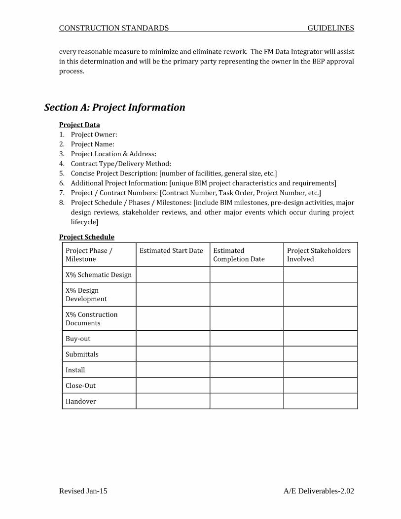
Section A: Project Information
Project Data
1. Project Owner:
2. Project Name:
3. Project Location & Address:
4. Contract Type/Delivery Method:
5. Concise Project Description: [number of facilities, general size, etc.]
6. Additional Project Information: [unique BIM project characteristics and requirements]
7. Project / Contract Numbers: [Contract Number, Task Order, Project Number, etc.]
8. Project Schedule / Phases / Milestones: [include BIM milestones, pre-design activities, major
design reviews, stakeholder reviews, and other major events which occur during project
lifecycle]
Project Schedule
Project Phase / Milestone
Estimated Start Date Estimated Completion Date
Project Stakeholders Involved
X% Schematic Design
X% Design Development
X% Construction Documents
Buy-out
Submittals
Install
Close-Out
Handover

CONSTRUCTION STANDARDS GUIDELINES
Revised Jan-15 A/E Deliverables-2.02
Key Project Contacts
List of lead BIM contacts for each organization on the project.
Role Organization Contact Name
Location E-Mail Phone
Project Manager(s)
BIM Manager(s)
Discipline Leads
Other Project Roles
Section B: Project Goals
Acknowledgment of BIM and FM Data Requirements
1. Identify Major BIM and FM Data Goals / Objectives: [state major BIM & FM data goals, actions
to implement, evidence the goal has been achieved, and participants involved]
Section C: BIM Uses
Acknowledgment of BIM and FM Data Requirements
1. Identify Major BIM uses on the project: [state major BIM use cases, their author, other users,
and file types (if applicable)]
2. Identify Project Assets: [see ‘Asset Requirements Matrix’ and indicate project assets]
3. Identify Elements to by Modeled and the responsible party to model such elements
4. Identify other areas of particular interest in BIM that require clarity: [origin point, scale,
model maintenance, other CAD/BIM Guidelines applicable, etc.]
Section D: BIM Use Staffing
Organizational Roles / Staffing
1. BIM for FM Roles and Responsibility:
2. BIM Use Staffing: [for each BIM & FM use selected, identify the team within the
organization(s) who will staff and perform that use and estimate the personal time required.

CONSTRUCTION STANDARDS GUIDELINES
Revised Jan-15 A/E Deliverables-2.02
This helps the owner understand the level of effort (i.e., staffing plan) expected by the team
members in delivery of the requirements.
BIM for FM Use
Organization Number of Total Staff for Use
Estimated Worker Hours
Location(s) Lead Contact
Section E: Collaboration Procedures
1. Collaboration Strategy: [describe how the project team will collaborate. Include items such
as communication methods, document management and transfer, file naming structure, and
record storage, etc.]
2. Meeting Procedures: [the following are examples that should be considered]
Meeting Type Project Stage Frequency Participants Location
BIM for FM Requirements Kick-Off
BIM for FM Execution Plan Demonstration
Design Coordination
Construction over-the-shoulder progress reviews
Any other BIM meetings that occur with multiple parties
CONSTRUCTION STANDARDS GUIDELINES
Revised Jan-15 A/E Deliverables-2.02
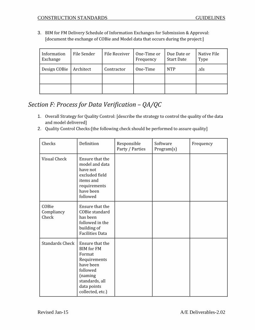
3. BIM for FM Delivery Schedule of Information Exchanges for Submission & Approval:
[document the exchange of COBie and Model data that occurs during the project:]
Information Exchange
File Sender File Receiver One-Time or Frequency
Due Date or Start Date
Native File Type
Design COBie Architect Contractor One-Time NTP .xls
Section F: Process for Data Verification – QA/QC
1. Overall Strategy for Quality Control: [describe the strategy to control the quality of the data
and model delivered]
2. Quality Control Checks:[the following check should be performed to assure quality]
Checks Definition Responsible Party / Parties
Software Program(s)
Frequency
Visual Check Ensure that the model and data have not excluded field items and requirements have been followed
COBie Compliancy Check
Ensure that the COBie standard has been followed in the building of Facilities Data
Standards Check Ensure that the BIM for FM Format Requirements have been followed (naming standards, all data points collected, etc.)

CONSTRUCTION STANDARDS GUIDELINES
Revised Jan-15 A/E Deliverables-2.02
Accuracy Ensure that all Facilities Data provided is 100% accurate
3. Accuracy and Tolerances:
a. Note: At any time during the project where the data errors grow to a point above 10% of
the entire data set; the owner reserves the right to take appropriate corrective action such
as having another party finish the BIM for FM deliverable at the expense of the responsible
party in error. The FDI’s role is to take preliminary steps to preclude this action. However,
if timely completion of the FM data process is delayed by an unreasonable amount of time,
the owner may direct such corrective actions be taken.
Section G: Technological Infrastructure Needs
1. Software [List software that COBie data and Model will be created and maintained in]
2. Modeling Content (conforming to TXST Asset Requirements Matrix)
Project Deliverables [list the BIM for FM deliverables for the project and the format in
which the information will be delivered]
BIM for FM Submittal Item
Stage Approximate Due Date
Format Notes
Record Design Model
Coordinated/ Combined Model
As-Coordinated/ As-built Trade Models
COBie
COBie Docs

CONSTRUCTION STANDARDS GUIDELINES
Revised Jan-15 A/E Deliverables-2.02
Section H: Process for Data Collection
1. Describe methods for collecting data during the project and how the team member intends
to coordinate and collaborate with the Facilities Data Integrator (FDI).
Section J: Update of the BEP
1. Provide Plan for revising BIM Execution Plan at each stage.
Attachments to Section 2 – BIM Execution Plan (BEP)
These are not attachments to the BEP but are critical parts of the requirements that must be
considered in the development of and updates to the BEP.
Exhibit 2.A - Grading Fields and Procedures
Exhibit 2.B - Sample Project Schedule
Exhibit 2.C – Close-Out Procedures
Coordinate the BEP development with each of the following and all parts of Exhibit E.
Section 3 – FM Data Requirements
Exhibit 3.A – Responsibility Assignment Matrix (RAM), Data Collection and Schedule (XLS
File)
Exhibit 3.B – Facilities Data Integrator (FDI) Role
Exhibit 3.C – Asset Type Matrix
Exhibit 3.D – FM Model Criteria

Exhibit 2.A: Schedule TXST - SAMPLE PROJECT SCHEDULE COBie Project
Month 1 Month 2 Month 3 Month 4 Month 5 Month 6 Month 7 Month 8 Month 9 Month 10 Month 11 Month 12 Month 13 Month 14 Month 15 Month 16Dec-13 Jan-14 Feb-14 Mar-14 Apr-14 May-14 Jun-14 Jul-14 Aug-14 Sep-14 Oct-14 Nov-14 Dec-14 Jan-14 Feb-15 Mar-15
Required Categories 8 2 4 6 7 7 8 8 8Required Fields/Columns 14 14 14 14 14 14 14 14 14
Proposed Quantity (Rows) 300 10 25 40 50 60 75 90 105
Required Categories 1 1Required Fields/Columns 5 5
Proposed Quantity (Rows) 1 1
Required Categories 3 3Required Fields/Columns 6 6
Proposed Quantity (Rows) 4 4
Required Categories 65 65Required Fields/Columns 10 10
Proposed Quantity (Rows) 100 100
Required Categories 5 2 3 5Required Fields/Columns 6 6 6 6
Proposed Quantity (Rows) 50 20 30 50
Required Categories 80 20 40 80 5 10 16 32 48 64 80Required Fields/Columns 17 6 6 6 17 17 17 17 17 17 17
Proposed Quantity (Rows) 100 25 50 100 5 10 20 40 60 80 100
Required Categories 100 25 50 100 20 5 10 20 40 60 80 100 100 100 100Required Fields/Columns 12 7 7 7 5 3 4 5 6 7 8 9 10 11 12
Proposed Quantity (Rows) 1500 375 750 1500 300 75 150 300 600 900 1200 1500 1500 1500 1500
Required Categories 20 5 10 20Required Fields/Columns 6 6 6 6
Proposed Quantity (Rows) 25 5 15 25
Required Categories 10 1 1 1 2 2 2 2 2 2 3 4 5 6 8 10Required Fields/Columns 10 10 10 10 10 10 10 10 10 10 10 10 10 10 10 10
Proposed Quantity (Rows) 1200 20 40 100 130 160 190 220 250 280 380 500 650 800 1000 1200O&M --> Cx -->
Required Categories 400 40 80 120 160 200 240 280 340 400Required Fields/Columns 8 8 8 8 8 8 8 8 8 8
Proposed Quantity (Rows) 500 50 100 150 200 250 300 350 425 500
Required Categories 1 1 1Required Fields/Columns 9 9 9
Proposed Quantity (Rows) 50 25 50
Proposed Quantity (Rows)Yellow milestone represents AE handover to Constructor
13-Attribute
14-Coordinate
Notes:
See Section 2: BIM Execution Plan with Exhibit 2.A.Required Categories (see Section 3 FM Data Specificaitons)
Zone & System row count based on COBie 2.24 method of one system/zone per row.
Drawings --> Submittals --> Submittals --> Model Viewpoints -->
Required Fields/Columns (See Section 3 with RAM Exhibit 3.A)
6-Type
7-Component
8-System
1-Contact
12-Document
Total
2-Facility
3-Floor
4-Space
5-Zone
E.2.B - Sample Project Schedule (Rev 03 - 9.24.15)

CONSTRUCTION STANDARDS GUIDELINES
Revised Jan-15 A/E Deliverables-2.02
Exhibit 2.B – Close-Out Procedures
End User Review & Acceptance
Test imports of the COBie data and documents may be performed leading up to final acceptance and
review. However, once the COBie file has been successfully test imported into AiM, the Facilities Data
Integrator (FDI) shall notify the Owner. The Owner then shall notify each end user to review assets
identified as belonging to their respective department (organization). Areas of particular interest in
review shall include those items that are shared between multiple end users/departments; ex: large
Utility Water Valves should be reviewed by both Facilities Plumbing and Utilities Water Distribution.
This review exercise will ensure that all assets are accepted and are being maintained after handover.
This also provides the owner’s personnel an opportunity to become familiar with the new assets
being added to their stewardship and to establish preventive maintenance (PM) procedures and/or
to apply standing PM’s to these newly uploaded assets.
Following notification to the owner, each end user shall have thirty (30) calendar days to review
assets and schedule a meeting with the Facilities Data Integrator (FDI) and Owner to address any
concerns and/or corrective actions that may be needed. If data concerns/issues have not been
provided in writing to the Facilities Data Integrator within this 30 day period, acceptance by the end
user shall be considered to be confirmed. The Facilities Data Integrator will be responsible to develop
and submit a schedule to the Owner for how end user concerns (if any) will be resolved.
Owner Review and Acceptance
Following End User Review and Acceptance, the Owner is responsible to review and provide final
comments for the Facilities Data Integrator to address with AEC team. If no comments have been
received by the Owner within thirty (30) calendar days of end user acceptance AND completion of
final punch list items, Owner acceptance shall be granted to the FDI. This process should generally
follow overall project substantial and final completion to ensure that all team members remain
engaged in the FM data process.
AEC Team Final Handover
Per the BIM Execution Plan, regularly scheduled COBie data and document submissions will be
reviewed and reported on by the Facilities Data Integrator at the agreed upon review intervals.
At the final scheduled COBie report, the Facilities Data Integrator shall provide the AEC team and
Owner a final punch list to address all outstanding items in the COBie data to be corrected. If all
outstanding items have not been completed within the subsequent fourteen (14) calendar days, the
owner may elect to take reasonable corrective actions as outlined in other parts of these
specifications.

CONSTRUCTION STANDARDS GUIDELINES
Revised Jan-15 A/E Deliverables-2.02
AEC team members that are contracted for COBie deliverables are responsible to validate (i.e., verify
by their own means and methods) their own work prior to regularly scheduled submissions to the
FDI. This will greatly shorten Corrective Action reports provided by the Facilities Data Integrator
and the meetings allocated to review these reports with the AEC team on a prescribed and regular
basis. The basic premise here is that progressive elaboration and “building up” of the FM data occurs
over multiple phases of the project duration.
Final Handover Deliverables Include (but may not be limited to):
● Project team compliance and conformance to the FM Data requirements (the FM Data
Specification).
● COBie Version 2.24 file (latest approved version) with all documents in one folder.
● Record Set Design Model (native files)
● As-built trade models (including all native files and one federated NWD file).
● Facilities Model with saved viewpoints of all COBie components per the FM Data requirements
(the FM Data Specification).

CONSTRUCTION STANDARDS GUIDELINES
Revised Jan-15 A/E Deliverables-2.02
Continue for the following Section 3 Exhibits:
Exhibit 3.A – Responsibility Matrix
Exhibit 3.B - Facilities Data Integrator
Exhibit 3.C - Asset Type Matrix (Full and Summary)
Exhibit 3.D - FM Model Criteria

Facilities Data Integrator will
be responsiblle to provide
information for all purple cells
indicated with "X" per Section
3 (FM Data Requirements).
See below for scheduled
delivery milestone.
(100% Design)
Design
Development
(100% Design) Construction
DocumentSubmittals Install Close Out Handover Instructions / Comments
Architect / Engineer Architect / Engineer Contractor Contractor Contractor Facilities Data Integrator
Introduction
Title n/a
2.24 Version n/a
Release n/a
Status n/a
Region n/a
Purpose n/a
Outline n/a
Contact Design Team
Contruction Team,
Subcontractors, &
Manufacturers from
Approved Submittals
Update if necessary Update if necessary
Contacts are the main personnel of contact for design team and
construction team. The other parties that get listed in Tab 1 are the
“Providers”. Providers are people/companies who have provided labor
and/or material to build the project. Providers will be discussed in Tab 6
(Types) in more detail.
A Email x x x x
Enter the contact’s e-mail address. Where a specific person is not
available, the company’s email address or URL is provided
(http://www.example.com/html).
B CreatedBy n/a
C CreatedOn n/a
D Category x x x x
This is the category (or project “role”) of the contact (or provider).
Categorize the list of Contacts as follows: (Contractor, Architect,
Engineer, Consultant, Manufacturer, Supplier, Owner, FM Data
Integrator
E Company x x x x
This is the name of the company that the contact (or provider) works for
during the project. Note: Use Owner provided vendor names for
manufacturers/suppliers and contractor codes for contractors.
F Phone x x x x
Enter the contact’s phone number or a main company phone number.
Format in the United States shall be 123-456-7890. For international
phone numbers, include the international exchange, as applicable,
before the local number.
G ExtSystem n/a
H ExtObject n/a
I ExtIdentifier n/a
J Department x x x
Enter a department code or name (description), as applicable, for the
contact (provider). If contact is a contractor, provide contractor company
name in this field.
K OrganizationCode n/a
L GivenName x x x x This is the first name of the contact (provider).
M FamilyName x x x x This is the last name of the contact (provider).
N Street x x x xEnter the contact’s street address or business address, as applicable.
O PostalBox x x x xEnter the contact’s postal box or business address, as applicable. Enter
as “PO Box 1234” for consistency.
P Town x x x x Enter the contact’s town of residence or the company town.
Q StateRegion x x x x
Enter the contact’s state or region for the applicable address. For
addresses in the United States, use the two character identifier for the
state (i.e., TX for Texas, LA for Louisiana, etc.). Do not write out the
entire state name.
R PostalCode x x x x
Enter the contact’s postal code for the applicable address. Typically, a
five (5) digit code applies (i.e. 77840). If a four (4) digit extension is
applicable then include that information as well in the following format
(i.e. 77840-0123).
S Country x x x x Enter the contact’s country. If in the United States, then use “USA”.
Facility xThe facility worksheet lists the “buildings” in the project and identifies the
measurement standards that apply to the COBie data. Facilities consist
of “floors” (see Tab 3 for Floors).
A Name x
This is a unique “facility” name (building name, site phase name, etc.).
Note: Facility names shall be obtained from the owner for each project
and shall correlate to the building number assigned by Space
Management.
B CreatedBy n/a
C CreatedOn n/a
D Category x
This is the category of the facility. Category relates to AiM ‘property type
code’, obtain list from Owner, CMMS Manager.
Input Category in this format: “Property Type Code” (Example: 2)
E ProjectName n/a
F SiteName n/a
G LinearUnits n/a
H AreaUnits n/a
I VolumeUnits n/a
J CurrencyUnits n/a
K AreaMeasurement n/a
L ExtSystem n/a
M ExtProjectObject n/a
N ExtProjectIdentifier n/a
O ExtSiteObject n/a
P ExtSiteIdentifier n/a
Q ExtFacilityObject n/a
R ExtFacilityIdentifier n/a
S Description x Provide an extended description of the facility.
T ProjectDescription x Provide an extended description of project.
U SiteDescription xProvide an extended description of the site of the project.
Note: Use campus name as default.
V Phase n/a
CO
Bie
2 W
ork
shee
t
CO
Bie
2 F
ield
Exhibit 3.A:
Responsibility Matrix
Architect will be responsiblle to provide
information for all green cells indicated with "X"
per Section 3 (FM Data Requirements). See below
for scheduled delivery milestone.
Contractor will be responsiblle to provide information for all
orange cells indicated with "X" per Section 3 (FM Data
Requirements). See below for scheduled delivery milestone.
E.3.A.- RAM with Schedule Rev 03 Dated 9.24.15 Page 1 of 7

(100% Design)
Design
Development
(100% Design) Construction
DocumentSubmittals Install Close Out Handover Instructions / Comments
Architect / Engineer Architect / Engineer Contractor Contractor Contractor Facilities Data IntegratorCO
Bie
2 W
ork
shee
t
CO
Bie
2 F
ield
Floor
The floor worksheet is associated with floors within a specific facility.
Floors can be vertical floors (ground, 1, 2, 3, other, etc.) as named by
the designer. Floors can also include basements, crawl spaces, roofs,
and site areas outside of the buildings when these areas have assigned
Components. Floors are horizontal planes that include specific “spaces”.
A Name x
This is a unique “floor” name for the facility and the primary key for all
floors. Choose from owner designated list for floor names. Floors shall
be named as integer: 1,2,3,4,5,6 etc.
*See NOTE 1 Below for more information
B CreatedBy n/a
C CreatedOn n/a
D Category n/a
E ExtSystem n/a
F ExtObject n/a
G ExtIdentifier n/a
H Description x Provide an extended description of the floor, per the Owners approval.
I Elevation x
Provide height above established project datum.
Note: The project datum shall be taken as Elevation 0’-0” at the ground
level (LEVEL 1).
J Height xProvide floor to floor height, as applicable. Provide the floor to floor
heights as listed on construction drawings.
Space Update Update if NecessaryUpdate if
Necessary
Update if
Necessary
The space worksheet includes the project’s space name. Spaces are
cross-referenced to floors from Tab 3. Space data also includes the
following: space function, floor identification, area measurement, and
the owner’s room number (final way finding nomenclature), if different
from the contract document space naming protocol.
A Name x x x x x
This is a unique “space” name for the. This field will be the room
numbers indicated on the final way finding. For exterior spaces, provide
location in reference to the building name (ex: 999-South, 999-East, 999-
North, 999-West)
Note: The current maximum number of allowable characters for a space
name is 15. Also, commas “,” are not allowed in space names.
B CreatedBy n/a
C CreatedOn n/a
D Category x x x x
Note: Space categories will be confirmed by Owner and chosen from
Texas Higher Education Coordinating Board (THECB) space use codes.
For list of space code obtain latest approved list from the THECB. At the
writing of this document, the latest list could be obtained from the link
below (page 71):
http://www.thecb.state.tx.us/reports/PDF/2520.PDF?CFID=10580093&C
FTOKEN=21211486
E FloorName x x x x xThis corresponds to what established floor the space exists on for floors
defined in Tab 3 (Floors).
F Description x x x x x
Provide space description, as applicable.
Note: IF way finding space name differs from name on construction
document then following the space description, provide the space name
as indicated on the contract documents / drawing which shall be used
with “: PLAN-” proceeding. (ex: “Mens Restroom : PLAN-104”)
G ExtSystem n/a
H ExtObject n/a
I ExtIdentifier n/a
J RoomTag x x
If the way finding room numbering system is different from the
construction document space naming convention from Column A, then
the space number on the construction drawings shall be used in this
field.
K UsableHeight x x x x This unit of measure is “feet”. Use decimal format (i.e., 10 feet 6 inches
of height would be 10.5, and 8 feet 4 inches of height would be 8.33).
L GrossArea n/a
M NetArea x x x x
Provide usable net area in each space, which shall be measured from
edge of finish wall to edge of finish wall. This unit of measure is “square
feet”. Use decimal format to two places (i.e., one hundred fifty six
square feet would be 156.00).
Zone Space Use ZonesUpdate & add
HVAC Zones
The zone worksheet is used to assign spaces (see Tab 4) into specific
groups, as needed by the Owner. The following shall be assumed the
minimum amount of zone types per COBie; however, the FDI shall
confirm each with the owner per facility:
A Name x x
Provide zone names. Within COBie, zones are specific to the
corresponding facility and should not correspond to areas in other
facilities. Zone should read per the following example below:
Maximum number of characters = 15
See Note 2 Below for more information*
B CreatedBy n/a
C CreatedOn n/a
D Category x xProvide category code for the named zone from the following list: HVAC
Support, Special Access, Non Occupancy, Facility Special.
E SpaceNames x x
Assign spaces to each named zone, as applicable. Given that multiple
zones will (could) exist and that spaces will be associated with each
zone, a space may be assigned to multiple zones.
F ExtSystem n/a
G ExtObject n/a
H ExtIdentifier n/a
I Description x x
This is a description of the Zone and should read per the following list:
HVAC Support Locations, Special Access Locations, Non Occupancy
Locations, Facility Specialty Locations
E.3.A.- RAM with Schedule Rev 03 Dated 9.24.15 Page 2 of 7

(100% Design)
Design
Development
(100% Design) Construction
DocumentSubmittals Install Close Out Handover Instructions / Comments
Architect / Engineer Architect / Engineer Contractor Contractor Contractor Facilities Data IntegratorCO
Bie
2 W
ork
shee
t
CO
Bie
2 F
ield
TypeUnique to Asset Group /
Classification
Update with Accepted
Submittals
Update if
Necessary
Update if
Necessary
The type worksheet categorizes components (see Tab 7) by model and
includes warranty information. See Exhibit 3c: Asset Type Matrix for
required types.
Note: Types shall be created for each model number within a family of
components (like AHU’s). Example: If there are three (3) different
models of AHU’s, then there would need to be three (3) unique “types” of
AHU’s to correspond. If Asset Type Matrix indicates an Asset Type as
group or on per building, then it is acceptable for that Type to not be
specific to a single model.
A Name x x x xProvide a name for the “type” of component which shall be unique
among all types.
B CreatedBy n/a
C CreatedOn n/a
D Category x x x x
This is the category of the type. Categories correlate to AiM “Asset
Groups” and should be chosen from Exhibit 3c: Asset Type Matrix
obtained by Owner CMMS Manager.
Note: Where the Asset Type Matrix appears to be missing an Asset Type
that is present in the project and seemingly important to facility
preventative maintenance, inquire with the Owner CMMS Manager.
E Description x x x x
Choose from “fixed” or “moveable” for the asset type to describe how the
asset is employed in the current project. Example: Fire Extinguishers
are movable assets.
F AssetType x x x x
Choose from “fixed” or “moveable” for the asset type to describe how the
asset is employed in the current project. Example: Fire Extinguishers
are movable assets.
G Manufacturer x x x
Product (type) manufacturer selected from the Contacts email
(Providers) (see Tab 1).
Note: This field corresponds to the “provider” of the product and is
different from Contacts although the providers are listed in the Contacts
tab of COBie. Providers are directly related to business entities that
have supplied labor and/or materials that will be subject to Warranty
terms.
H ModelNumber x x x
Provide product (type) model number (typically, provided before
installation in accepted submittals). Not necessary for Asset Types that
are grouped or ‘one per bulding’.
I WarrantyGuarantorParts x x xProduct (type) warranty provider for parts selected from the Contacts
email (see Tab 1).
J WarrantyDurationParts x x x
Provide the parts warranty duration in years for the product (type) in the
units of Column M.
Note: Warranty start dates correspond with substantial completion per
phased turnover, unless directed otherwise by available documents or
owner.
K WarrantyGuarantorLabor x x xProduct (type) warranty for labor selected from the Contacts email (see
Tab 1).
L WarrantyDurationLabor x x x
Provide the labor warranty duration in years for the product (type) in the
units of Column M.
Note: Warranty start dates correspond with substantial completion per
phased turnover, unless directed otherwise by available documents or
owner.
M WarrantyDurationUnit x x x Duration unit shall be in “year”.
N ExtSystem n/a
O ExtObject n/a
P ExtIdentifier n/a
Q ReplacementCost x x x Replacement / purchase cost for the type of product.
R ExpectedLife x x xProvide the expected service life for the product (type) in units of time in
years.
S DurationUnit x x x Duration unit shall be in “year”.
T WarrantyDescription x x x
Provide warranty description if there are special warranties for the
product. For example; if there is a 5 year warranty for a water heater’s
tank, and a standard 1 year warranty for all other components of the
water heater, include these details in the warranty description field.
Actual warranty documents will be attached to the corresponding type,
when available. Otherwise, leave this field blank.
ComponentUpdate with Accepted
Submittals
Update if
Necessary
Update if
Necessary
The component worksheet contains the unique equipment from the
project that is specifically mentioned in the latest Asset Type Matrix as
seen in Exhibit 3C. For example: Components that can be seen in the
field are not incorporated into the file unless specifically called for in
Exhibit 3c: Asset Type Matrix attachment.
A Name x x x x
Note: Components that are scheduled on the contract documents shall
have the same name (i.e., mark number) as the equipment schedule.
See below for specific components naming conventions and content for
those components that are not uniquely named on contract drawings.
*See NOTE 3 below for more information
B CreatedBy n/a
C CreatedOn n/a
D TypeName x x x xProvide cross reference to the previously established type names on Tab
6.
E SpaceNames x x x xProvide cross reference to the previously established space names on
Tab 4.
F Description x x x x
Provide a brief description of the component. If the component is located
in a large common area provide a location descriptor too. Ex: south east
smoke detector
G ExtSystem n/a
H ExtObject n/a
I ExtIdentifier n/a
J SerialNumber x xProvide the component serial number. If no serial number provided or
available then “n/a” is entered in this field.
K InstallationDateSpecial Warranty
Itemsx
Provide the component installation date. This date shall be taken as the
Substantial Completion date, unless directed otherwise by available
documents or owner.
L WarrantyStartDateSpecial Warranty
Itemsx
Provide the component warranty start date. This date shall be taken as
the Substantial Completion date, unless directed otherwise by available
documents or owner.
M TagNumber x x x x
Provide the component tag number (i.e., brass tags, name tags,
security/fire points, etc.) assigned and attached during construction
and/or operations, as applicable.
N BarCode If available If available
O AssetIdentifier n/a
E.3.A.- RAM with Schedule Rev 03 Dated 9.24.15 Page 3 of 7

(100% Design)
Design
Development
(100% Design) Construction
DocumentSubmittals Install Close Out Handover Instructions / Comments
Architect / Engineer Architect / Engineer Contractor Contractor Contractor Facilities Data IntegratorCO
Bie
2 W
ork
shee
t
CO
Bie
2 F
ield
System Building Systems
Update & add
HVAC & Elec
Parent/Child
The system worksheet defines the building systems that are built from
components. This worksheet allows multiple components to be
assigned to a system.
Minimum Systems are as follows:
● HVAC Children - (provide HVAC equipment downstream of air
handling devices)
● Electrical Children - (provide equipment downstream of panel)
● Building Systems – (provide system information per indicated in Asset
Type Matrix)
A Name x x
Provide a unique name for each building system. Refer to Exhibit 3c:
Asset Type Matrix for building systems. For Parent/Child Systems
provide the component name in the System name. Named by Building
System and Building Number, Example: HVAC-866. For Parent/Child
relationships, systems shall be named by the parent asset.
Maximum number of characters = 25
B CreatedBy n/a
C CreatedOn n/a
D Category x
This is the category of the system. Categories shall be assigned per list
below:
● HVAC Children
● Electrical Children
● Building Systems
Maximum number of characters = 25
E ComponentNames x
Provide list of components that are part of this unique system. Every
component is assigned to at least a primary system. Components are
assigned based on the system they serve, not based upon the system
that they are supplied from. For example, if a Variable Frequency Drive
(VFD) is supplied by an electrical system but serves an Air Handling Unit
(AHU) then the VFD is grouped within the same system as the AHU.
F ExtSystem n/a
G ExtObject n/a
H ExtIdentifier n/a
I Description x x Provide description of System.
Spare n/a
Resource n/a
JobManufacturer
recommended PM's
from O&M
The job worksheet organizes facility Preventative Maintenance Plans
and Procedures
A Name x Provide a unique name for each job record.
B CreatedBy n/a
C CreatedOn n/a
D Category x Preventative Maintenance Procedure shall be the Job Category.
E Status n/a
F TypeName x What type of item is the job associated with from Tab 6 (Type)?
G Description xWhat needs to be done for this job record? Individual tasks can be
separated (in XLS format) by commas.
H Duration x Provide the estimated duration of the job for units listed in Column I.
I DurationUnit x Provide the duration time unit (i.e., minutes, hours, days, etc).
J Start x Provide start date for job.
K TaskStartUnit x
Provide the unit of time that the job is to be performed relative to the
start date in Column J. Use month or year. That is, using the start date,
will the frequency period key off of the month for the start or the year for
the start. Jobs are organized by monthly increments or annual
increments.
L Frequency x
Provide frequency (interval period) that the job is to be performed per
the Column M units. Frequency shall be month (for monthly) and year
(for annual).
M FrequencyUnit x Provide the frequency time unit for the job (i.e., month or year).
N ExtSystem n/a
O ExtObject n/a
P ExtIdentifier n/a
Q TaskNumber n/a
R Priors n/a
S ResourceNames n/a
E.3.A.- RAM with Schedule Rev 03 Dated 9.24.15 Page 4 of 7

(100% Design)
Design
Development
(100% Design) Construction
DocumentSubmittals Install Close Out Handover Instructions / Comments
Architect / Engineer Architect / Engineer Contractor Contractor Contractor Facilities Data IntegratorCO
Bie
2 W
ork
shee
t
CO
Bie
2 F
ield
Document Drawings
Update & add
Submittal with
Approval
Update and add
Commissioning and
O&M's
Complete Model Linking
The document worksheet is an index of the physical documents (in
electronic format) associated with the project and links the documents to
spaces, components, and systems. Only provide documents that
reference a space, component, or system; for example: do not provide
concrete testing documents as concrete is not a space, component, or
system.
*See NOTE 4 for more info
A Name x x x xProvide a unique name for each document record.
*See NOTE 5 for more info
B CreatedBy n/a
C CreatedOn n/a
D Category x x x xProvide the document category from the list below:
*See NOTE 5 for more info
E ApprovalBy n/a
F Stage n/a
G SheetName x x x x
Provide the COBie worksheet name (Tab name) that the document is
being cross referenced to such as type, component, etc.
A document will be referenced to the lowest common denominator of
facilities data. For example, submittal data that applied to all equipment
in a certain type will be attached to the Type (Tab 6) level and not to
each Component (Tab 7). Similarly, Grounding Data for a facility will
cover several types, and components, and systems so the document will
be cross referenced to the System(s) applicable in order to limit the
number of documents in the database.
H RowName x x x x
Provide the corresponding row name (Column A) for the above sheet
(Tab name) that the document is being cross referenced to. Some
documents will need to be cross referenced to several row names and
this is possible.
I Directory x x x x Provide the directory or location where the document can be found.
J File x x x xThis is the actual file name of the document and should be an exact
match to what will be found in the file directory.
K ExtSystem n/a
L ExtObject n/a
M ExtIdentifier n/a
N Description x x x xProvide a description of the document in short form if the previous
columns of information are insufficient.
O Reference n/a
Attribute Add submittal dataUpdate if
Necessary
Update if
NecessaryReverse system & zones
The attribute worksheet typically captures design parameters Attributes
for Components, Spaces, Types & Systems.
See Exhibit 3c: Asset Type Matrix for required attributes per type.
*See NOTE 6 for more info
A Name x x x x
Provide unique name for each record, this can be done by giving a short
description of the attribute and then following with the name of the
component, space, type or system to which the attribute is associated
with. Ex: “capacity–Component Name”
Maximum number of characters = 25
B CreatedBy n/a
C CreatedOn n/a
D Stage n/a
E SheetName x x x xProvide the COBie worksheet name (Tab name) that the document is
being cross referenced to such as type, component, etc.
F RowName x x x x
Provide the corresponding row name (Column A) for the above sheet
(Tab name) that the document is being cross referenced to. Some
documents will need to be cross referenced to several row names and
this is possible.
G Value x x x x
Value contains the actual description to the component, space, floor, or
type that is to receive an attribute. For instance, if Gallons per Minute for
a Pump was a desired field to capture, the actual GPM number (ex: 300
GMP) would be the value.
H Unit x x x x
Unit describes the value. For example, if dimensions of a pump should
be captured, inches/feet/centimeters/millimeters would be the unit to
describe this dimension.
I ExtSystem n/a
J ExtObject n/a
K ExtObject n/a
L Description x x x xUse description to describe the attribute used; ex: “supply fan capacity”,
“HVAC CHILDREN”, “HVAC SUPPORT LOCATION”, etc.
Coordinate Site EquipmentUpdate if
NecessaryUpdate if Necessary
Coordinates will only be used for Site components. Coordinates shall be
provided with an accuracy of within 1 foot or the 6th decimal place in
Latitude/Longitude decimal degrees.
A Name x x x
Provide unique name for each record. Enter the name of the object
being located and “COORDINATE” for the coordinate name. Ex: “SS
MANHOLE 1 COORDINATE”
B CreatedBy n/a
C CreatedOn n/a
D Category x x x Enter “point”.
E SheetName x x xProvide the COBie worksheet name (Tab name) that the document is
being cross referenced to such as type, component, etc.
F RowName x x x
Provide the corresponding row name (Column A) for the above sheet
(Tab name) that the document is being cross referenced to. Some
documents will need to be cross referenced to several row names and
this is possible.
G CoordinateXAxis x x xThis field should contain the latitudinal coordinate (in degrees) of the
object being described, IF AVAILABLE
H CoordinateYAxis x x xThis field should contain the latitudinal coordinate (in degrees) of the
object being described, IF AVAILABLE
I CoordinateZAxis x x x This field should be left empty.
J ExtSystem n/a
K ExtIdentifier n/a
L ExtObject n/a
Connection n/a
Issue n/a
PickLists n/a
E.3.A.- RAM with Schedule Rev 03 Dated 9.24.15 Page 5 of 7
(100% Design)
Design
Development
(100% Design) Construction
DocumentSubmittals Install Close Out Handover Instructions / Comments
Architect / Engineer Architect / Engineer Contractor Contractor Contractor Facilities Data IntegratorCO
Bie
2 W
ork
shee
t
CO
Bie
2 F
ield
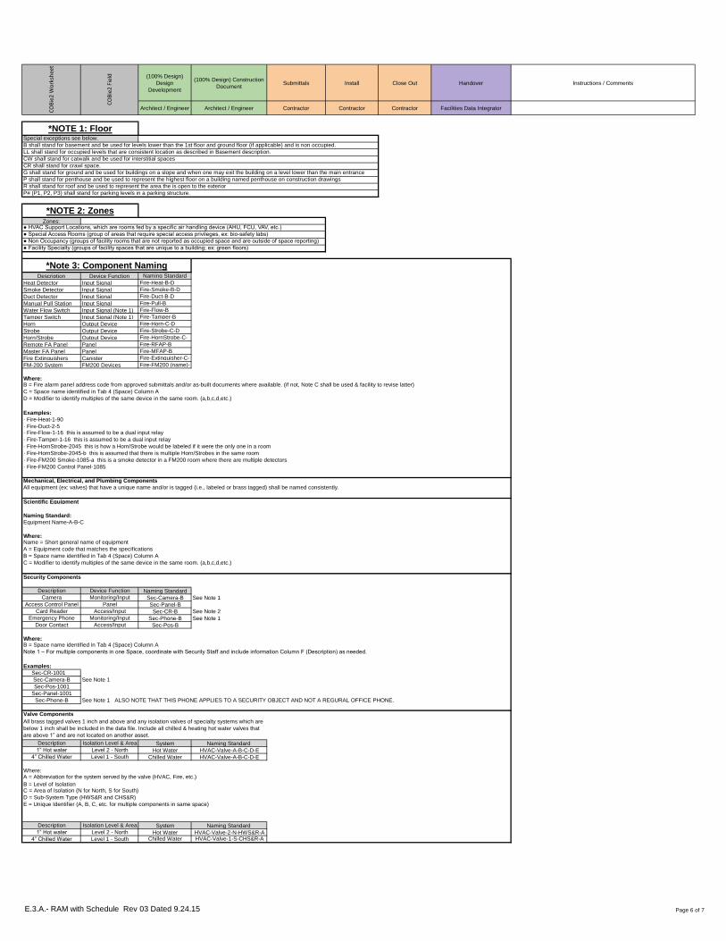
Zones:
Description Device Function Naming Standard
Heat Detector Input Signal Fire-Heat-B-D
Smoke Detector Input Signal Fire-Smoke-B-D
Duct Detector Input Signal Fire-Duct-B-D
Manual Pull Station Input Signal Fire-Pull-B
Water Flow Switch Input Signal (Note 1) Fire-Flow-B
Tamper Switch Input Signal (Note 1) Fire-Tamper-B
Horn Output Device Fire-Horn-C-D
Strobe Output Device Fire-Strobe-C-D
Horn/Strobe Output Device Fire-HornStrobe-C-
Remote FA Panel Panel Fire-RFAP-B
Master FA Panel Panel Fire-MFAP-B
Fire Extinguishers Canister Fire-Extinguisher-C-
FM-200 System FM200 Devices Fire-FM200 (name)-
Where:
Examples:
· Fire-Heat-1-90
· Fire-Duct-2-5
Scientific Equipment
Naming Standard:
Equipment Name-A-B-C
Where:
Security Components
Description Device Function Naming Standard
Camera Monitoring/Input Sec-Camera-B See Note 1
Access Control Panel Panel Sec-Panel-B
Card Reader Access/Input Sec-CR-B See Note 2
Emergency Phone Monitoring/Input Sec-Phone-B See Note 1
Door Contact Access/Input Sec-Pos-B
Where:
Examples:
Sec-CR-1001
Sec-Camera-B See Note 1
Sec-Pos-1001
Sec-Panel-1001
Sec-Phone-B See Note 1 ALSO NOTE THAT THIS PHONE APPLIES TO A SECURITY OBJECT AND NOT A REGURAL OFFICE PHONE.
Valve Components
Description Isolation Level & Area System Naming Standard
1” Hot water Level 2 - North Hot Water HVAC-Valve-A-B-C-D-E
4” Chilled Water Level 1 - South Chilled Water HVAC-Valve-A-B-C-D-E
Where:
B = Level of Isolation
Description Isolation Level & Area System Naming Standard
1” Hot water Level 2 - North Hot Water HVAC-Valve-2-N-HWS&R-A
4” Chilled Water Level 1 - South Chilled Water HVAC-Valve-1-S-CHS&R-A
*NOTE 2: Zones
● Facility Specialty (groups of facility spaces that are unique to a building; ex: green floors)
● Special Access Rooms (group of areas that require special access privileges, ex: bio-safety labs)
● HVAC Support Locations, which are rooms fed by a specific air handling device (AHU, FCU, VAV, etc.)
● Non Occupancy (groups of facility rooms that are not reported as occupied space and are outside of space reporting)
Name = Short general name of equipment
A = Equipment code that matches the specifications
B = Space name identified in Tab 4 (Space) Column A
C = Modifier to identify multiples of the same device in the same room. (a,b,c,d,etc.)
B = Space name identified in Tab 4 (Space) Column A
E = Unique Identifier (A, B, C, etc. for multiple components in same space)
G shall stand for ground and be used for buildings on a slope and when one may exit the building on a level lower than the main entrance
P shall stand for penthouse and be used to represent the highest floor on a building named penthouse on construction drawings
CR shall stand for crawl space.
P# (P1, P2, P3) shall stand for parking levels in a parking structure.
R shall stand for roof and be used to represent the area the is open to the exterior
All brass tagged valves 1 inch and above and any isolation valves of specialty systems which are
below 1 inch shall be included in the data file. Include all chilled & heating hot water valves that
are above 1” and are not located on another asset.
*Note 3: Component Naming
*NOTE 1: Floor
B shall stand for basement and be used for levels lower than the 1st floor and ground floor (if applicable) and is non occupied.
CW shall stand for catwalk and be used for interstitial spaces
LL shall stand for occupied levels that are consistent location as described in Basement description.
Special exceptions see below.
B = Fire alarm panel address code from approved submittals and/or as-built documents where available. (if not, Note C shall be used & facility to revise latter)
C = Space name identified in Tab 4 (Space) Column A
D = Modifier to identify multiples of the same device in the same room. (a,b,c,d,etc.)
· Fire-Flow-1-16 this is assumed to be a dual input relay
· Fire-Tamper-1-16 this is assumed to be a dual input relay
· Fire-HornStrobe-2045 this is how a Horn/Strobe would be labeled if it were the only one in a room
· Fire-HornStrobe-2045-b this is assumed that there is multiple Horn/Strobes in the same room
· Fire-FM200 Smoke-1085-a this is a smoke detector in a FM200 room where there are multiple detectors
· Fire-FM200 Control Panel-1085
All equipment (ex: valves) that have a unique name and/or is tagged (i.e., labeled or brass tagged) shall be named consistently.
Mechanical, Electrical, and Plumbing Components
Note 1 – For multiple components in one Space, coordinate with Security Staff and include information Column F (Description) as needed.
A = Abbreviation for the system served by the valve (HVAC, Fire, etc.)
C = Area of Isolation (N for North, S for South)
D = Sub-System Type (HWS&R and CHS&R)
E.3.A.- RAM with Schedule Rev 03 Dated 9.24.15 Page 6 of 7

(100% Design)
Design
Development
(100% Design) Construction
DocumentSubmittals Install Close Out Handover Instructions / Comments
Architect / Engineer Architect / Engineer Contractor Contractor Contractor Facilities Data IntegratorCO
Bie
2 W
ork
shee
t
CO
Bie
2 F
ield
Document Types Naming Standard
System Readiness CX - SRC
Functional CX - FPT
Integrated Systems CX - IST System
Submittals SUB - Equipment
Finish/Hardware Drawing - Name
Point to Point List Drawing - PTP
Operations & OM - Equipment
Model Viewpoints Model – HTML Name
Warranty Warranty - Equipment
Drawing Drawing - Drawing
Training Training – Unique
TAB TAB – Unique
Manufacturer Testing TEST – Equipment
Field Image Image – Equipment
Document Examples:
● Drawings
● Submittal
● Schedule
● Test Reports
● Operations and
● Warranties
● Model
● Training Videos
● Testing Balance
● Image
*NOTE 6: AttributesSome attributes have been included per owner’s request. These include attributes for spaces (recording the VAV that feeds into the room),
VAV boxes (recording which space it will feed into). Where there is multiple attributes surrounding a single object, like a motor, attributes will
be numbered (1,2,3, etc.).
*NOTE 4: DocumentsAll project drawings will be assigned to spaces represented in them. For example, if A101 is seen in, Architectural, Electrical, Plumbing, &
Mechanical floor plan drawings, each of those drawings should be attached to A101 as a COBie Document. Documents to be provided are
Architectural, Electrical, Plumbing, Mechanical, AV/IT floor plans attached to spaces, and Equipment schedules attached to components.
Submittals and O&M documents shall contain only information that is pertinent to the type that the document is being attached to. For
example, it is not acceptable to attach a submittal on air handlers to all air handlers on the project, unless they happen to be all of the same
manufacturer and model and type.
Field images are taken for each asset immediately prior to cover up (excluding interior lighting, fire alarm devices, & HVAC controls).
*NOTE 5: Documents
E.3.A.- RAM with Schedule Rev 03 Dated 9.24.15 Page 7 of 7

CONSTRUCTION STANDARDS GUIDELINES
Revised Jan-15 A/E Deliverables-2.02
Exhibit 3.B - Facilities Data Integrator Role
Role: Facilities Data Integrator (FDI)
Description: Manager of BIM for FM Process on Design/Construction Projects
Overall Responsibility: Ensure correct execution of the TXST BIM for FM Requirements
Specific Responsibilities Include (but are not limited to):
Planning / Programming Phase
● Determine feasibility of FM data collection for proposed projects.
● Confirm FM data requirements are to be employed on certain design/construction jobs.
● Update (if needed) and provide latest BIM for FM requirements to new projects.
● For unique projects, reconcile the FM requirements and update the FM requirements.
● Setup project responsibilities and roles per Owner’s directives and BIM for FM requirements.
● Integrate FM data requirements into the project delivery process for RFQ, RFP, and other
contracting processes for the design, construction, commissioning, and other team members.
● Establish budget allocations in the capital budget for FM data functions on the project.
● Review and assess project team members (i.e., AEC teams) for their ability to comply with
requirements (via RFQ and RFP activities) and the review of “draft” BIM Execution Plans.
● Other duties as required to implement the TXST BIM and FM requirements and specifications.
Design / Construction / Commissioning Phases
● Hold kick-off and orientation meetings detailing BIM for FM requirements.
● Review and assess submitted BIM Execution Plans from AEC project team members.
● Hold meetings for BIM for FM Execution Plan review and project coordination planning including
deliverable schedules.
● Adjust AEC team BIM for FM scope, if necessary, and in accordance with Owner’s directives and
specific or unique project requirements not listed in the latest FM data specifications.
● Monitor progress, assess quality, and confirm accuracy of ongoing data collection and validation
process.
● Hold regular project meetings with project team members to discuss the progress and quality of
the deliverables and the schedule for incremental deliverable development.
● Conduct payment application reviews of the FM data deliverables for AEC payment process.
● Inspect and evaluate (i.e., grade) deliverables in accordance with BIM for FM requirements and
project schedules.
● Integrate owner data into project data set, as applicable for OFOI / OFCI assets.
● Integrate project team data deliverables into latest acceptable COBie format for test uploads to
CMMS (AiM).

CONSTRUCTION STANDARDS GUIDELINES
Revised Jan-15 A/E Deliverables-2.02
● Conduct several incremental / test uploads to AiM to confirm data migration is functional. If not
functional, take corrective actions as needed.
● Ensure facility models are setup for O&M facility viewer and integration with CMMS model
linking functions.
● Provide necessary minor adjustments to models to make them lighter and user friendly for O&M
purposes (ex: transparent ceilings and site ground, contrast colors appropriately, etc).
● Other duties as required to implement the TXST BIM and FM requirements and specifications.
Qualifications for the Facilities Data Integrator (FDI) Role
● Any team member (Architect, Engineer, General Contractor, Consultant, Commissioning Agent,
or Owner’s Representative, etc.) that can show successful management of past FM Data
(specifically, the COBie 2.24 format) projects that have been imported to a client’s (i.e., owner’s)
CMMS and are currently in use for Asset Management functions.
○ provide references of qualifying projects
○ provide references of owners/clients currently using the imported COBie formatted data for
Asset Management
● Any team that can demonstrate understanding of the TXST BIM for FM requirements and provide
an example for how each section is carried out using a sample higher education project of their
choice. Samples should include the following, at a minimum:
○ COBie sample files shall successfully import to TXST AiM and include a minimum of the
following for sample data sets: 10 contacts, 5 spaces, 1 zone, 5 types, 10 components, 2
systems, 10 documents, and 15 equipment attributes matching the most current TXST
requirements.
○ Ability to complete the TXST BIM Execution Plan outlining their role as a Facilities Data
Integrator on the sample project.
● It is recommended that the Facilities Data Integrator (FDI) chosen for a specific project not be
someone who already has a substantial responsibility with BIM for FM data production
(authorship) on that project. This would typically exclude the AEC team from functioning as the
FDI. This criteria allows for objectivity (independent verification) and helps to prohibit a conflict
of interest in the evaluation (grading) functions by the FDI. Since the FDI’s role is essentially data
commissioning, independent quantity and quality verification is desirable since the information
will be used in operational workflow processes.

Exhibit 3.C Asset Type Matrix
Acid Tank Uniformat TNK-ACID PLUMB Facilities Plumbing storage type
D2060.40 nominal capacity
Master Format effective capacity
22 66 83 operating weight
Omni-class number of sections
23-27 29 19
ADA Doors & Openers Uniformat ADA ELEC Facilities Electric
B2050.90
Master Format
08 71 00
Omni-class
23-17 19 11
Air Compressor Uniformat ACU PLUMB Facilities Plumbing & Facilities ACpower*
D2050 electrical panel name*
Master Format capacity*
22 15 00 has hot gas bypass
Omni-class ideal capacity
23-27 21 00 nominal capacity
max pressure
compressor type
Air Dryer Uniformat ADY PLUMB Facilities Plumbing & Facilities ACpower*
D2050 electrical panel name*
Master Format capacity*
22 15 00 refigerant type
Omni-class pressure dew point
23-33 47 00 max pressure
Air Handler Unit Uniformat AHU HVAC Facilities AC & Utilities Tech Servicespower*
D3050.50 electrical panel name*
Master Format capacity*
23 70 00 air filter type
Omni-class return fan capacity
23-33 25 00 supply fan capacity
fan ext pressure drop
chilled water rate
coil flow
coil velocity
coil capacity
coil pressure drop
entering air temp db/wb
leaving air temp db/wb
entering water temp
leaving water temp
Air Handler Unit - Clean Room Uniformat AHU-CLR HVAC Facilities AC & Utilities Tech Servicespower*
D3050.50 electrical panel name*
Master Format capacity*
23 70 00 air filter type
Omni-class return fan capacity
23-33 25 00 supply fan capacity
fan ext pressure drop
chilled water rate
coil flow
coil velocity
coil capacity
coil pressure drop
entering air temp db/wb
leaving air temp db/wb
entering water temp
leaving water temp
Air Handler Unit - Elevator Uniformat AHU-ELV HVAC Facilities AC & Utilities Tech Servicespower*
D3050.50 electrical panel name*
Master Format capacity*
23 70 00 air filter type
Omni-class return fan capacity
23-33 25 00 supply fan capacity
fan ext pressure drop
chilled water rate
coil flow
coil velocity
coil capacity
coil pressure drop
entering air temp db/wb
leaving air temp db/wb
entering water temp
leaving water temp
ReviewAttribute Sheet
"Attributes"
Asset Group /
COBie "Type Category"Classification Abbreviation Comments System
E.3.C - Full (Rev 03 Dated 9.24.15) Page 1 of 42

Annunciators Uniformat FIR-ANNUNC FIRE ALARM Util Tech Services
D7050.10
Master Format
28 31 23
Omni-class
23-29 31 11
Auditorium Seating Uniformat STG One per building FURNITURE Facilities Maintenance
E2010.70
Master Format
12 61 00
Omni-class
23-21 25 11
Automatic Doors Uniformat ELEC
B2050.10
Master Format
08 42 29
Omni-class
23-17 19 11 31
Automatic Transfer Switch Uniformat ATS ELEC Utilities Electric & Facilities Electric & ITpower*
D5010.70 electrical panel name*
Master Format capacity*
26 36 23
Omni-class
23-35 37 11
Auxiliary Water Pump Uniformat PMP-AUX Facilties Plumbing power*
D2010.20 electrical panel name*
Master Format capacity*
22 11 23 feet head
Omni-class suction pressure
23-27 17 00 type (endsuction, inline, etc)
max temp
max pressure
suction size
discharge size
Backflow Preventor Uniformat BFP PLUMB Facilities Plumbing capacity*
G3010.10 type (double check, etc.)
Master Format
33 12 13
Omni-class
23-27 31 11
Battery Systems Uniformat BES ELEC Utilities Electric & Facilities Electric & ITpower*
D5010.20 electrical panel name*
Master Format capacity*
26 33 00 supply voltage
Omni-class supply voltage offset
23-35 19 00
Blue Lights & Phones Uniformat ECB SECURITY Facilites Electric power*
D6020.20 electrical panel name*
Master Format
27 32 26
Omni-class
23-37 27 00
Boiler Uniformat BGO HVAC Facilities AC & Utilities Tech Servicespower*
D3020.10 electrical panel name*
Master Format capacity*
23 52 00 energy source
Omni-class partial load efficiency curves
23-33 11 00 outlet temperature range
nominal energy consumption
nominal efficiency
heat output
pressure rating
normal operating pressure set point
maximum allowable pressure
maximum boiler temperature
boiler design temperature
water storage capacity
type of boiler
number of passes
E.3.C - Full (Rev 03 Dated 9.24.15) Page 2 of 42

Boiler Feedwater Pump Uniformat PMP-BFW PLANT Utilities Water & Facilities Plumbingpower*
D3020.10 electrical panel name*
Master Format capacity*
23 53 13 feet head
Omni-class suction pressure
23-27 17 00 type (endsuction, inline, etc)
max temp
max pressure
suction size
discharge size
Building Sump Pumps Uniformat PMP-SMP PLUMB
D2030.10
Master Format
22 14 29
Omni-class
23-27 17 00
Burglar Alarm Uniformat SEC-ALM SECURITY Access Services & Facilites Electric
D7010.50
Master Format
28 16 00
Omni-class
23-29 11 23
Carbon Monoxide Detector Uniformat CMD One per building SAFETY Risk Management
D7050.10
Master Format
28 31 49
Omni-class
23-27 11 27 17
Card Readers Uniformat SEC-CARD SECURITY Access Services
D7010.10
Master Format
08 74 13
Omni-class
23-29 13 13
Ceiling Tile Uniformat CLG-TIL One per building ARCHITECTURAL Facilities Maintenance
C1070.10
Master Format
09 51 00
Omni-class
23-15 19 15
Chemical Pump Uniformat PMP-CHE PLUMB Facilities Plumbing power*
D2060.40 electrical panel name*
Master Format capacity*
22 66 00 feet head
Omni-class suction pressure
23-27 17 00 type (endsuction, inline, etc)
max temp
max pressure
suction size
discharge size
Chilled Water Expansion Tank Uniformat TNK-CHW HVAC Facilities AC capacity*
D3050.10 tank volume
Master Format max system temp
23 00 00 max system pressure
Omni-class
23-27 29 19
Chilled Water Pump Uniformat PMP-CHW HVAC Facilities AC & Utilitiespower*
D3050.10 electrical panel name*
Master Format capacity*
23 21 23 feet head
Omni-class suction pressure
23-27 17 00 type (endsuction, inline, etc)
max temp
max pressure
suction size
discharge size
Chilled Water Pump - Special ProcessUniformat PMP-SP HVAC Facilities AC power*
D3050.10 electrical panel name*
Master Format capacity*
23 21 23 feet head
Omni-class suction pressure
23-27 17 00 type (endsuction, inline, etc)
max temp
max pressure
suction size
discharge size
E.3.C - Full (Rev 03 Dated 9.24.15) Page 3 of 42

Chilled/Heating Water Isolation ValvesUniformat VAL-HVAC HVAC Facilities AC & Utilities Tech Services & Utilitiescapacity*
D2030.90 maximum operating pressure
Master Format valve operation
23 20 00 type of valve
Omni-class location in space
23-27 31 00
Chiller Compressor Uniformat CMP-CHR PLANT PLANT power*
D3030.10 electrical panel name*
Master Format capacity*
23 61 00 nominal capacity
Omni-class ideal capacity
maximum allowable pressure
compressor speed
compressor stage
drive method
engine hp
tank size in gallons
type of oil
oil weight
Chillers Uniformat CHR & Dx Chillers HVAC Utilites Plant power*
D3030.10 electrical panel name*
Master Format capacity*
23 64 00 chiller cooling capacity
Omni-class chilled water inlet/outlet temp
23-33 21 00 chilled water flow rate
chilled water pressure drop
cooling water inlet/outlet temp
cooling water flow rate
cooling water pressure drop
hot water inlet/outlet temp
hot water flow rate
hot water pressure drop
Cisterns Uniformat CISTERN PLUMB Facilities Plumbing capacity
G3030.70
Master Format
33 47 00
Omni-class
23-27 29 11
Clocks Uniformat CLK One per building FURNITURE Facilities Maintenance
D6060.50
Master Format
27 53 13
Omni-class
23-21 37 13 13
Communication Manhole Uniformat MAN-COM ELEC Utilities Electric & IT location in space
G5010.10 GPS location
Master Format
33 81 26
Omni-class
23-17 11 27 23
Compressors Uniformat CMP AHU's, A/C equipment, refrigeration, etc.HVAC Facilities AC power*
D3030.10 electrical panel name*
Master Format capacity*
23 61 00 nominal capacity
Omni-class ideal capacity
23-27 21 00 maximum allowable pressure
compressor speed
compressor stage
drive method
engine hp
tank size in gallons
type of oil
oil weight
Condensate Pumps Uniformat PMP-CON PLANT Facilities AC & Utilitiespower*
D3050.30 electrical panel name*
Master Format capacity*
23 22 23 feet head
Omni-class suction pressure
23-27 17 00 type (endsuction, inline, etc)
max temp
max pressure
suction size
discharge size
E.3.C - Full (Rev 03 Dated 9.24.15) Page 4 of 42
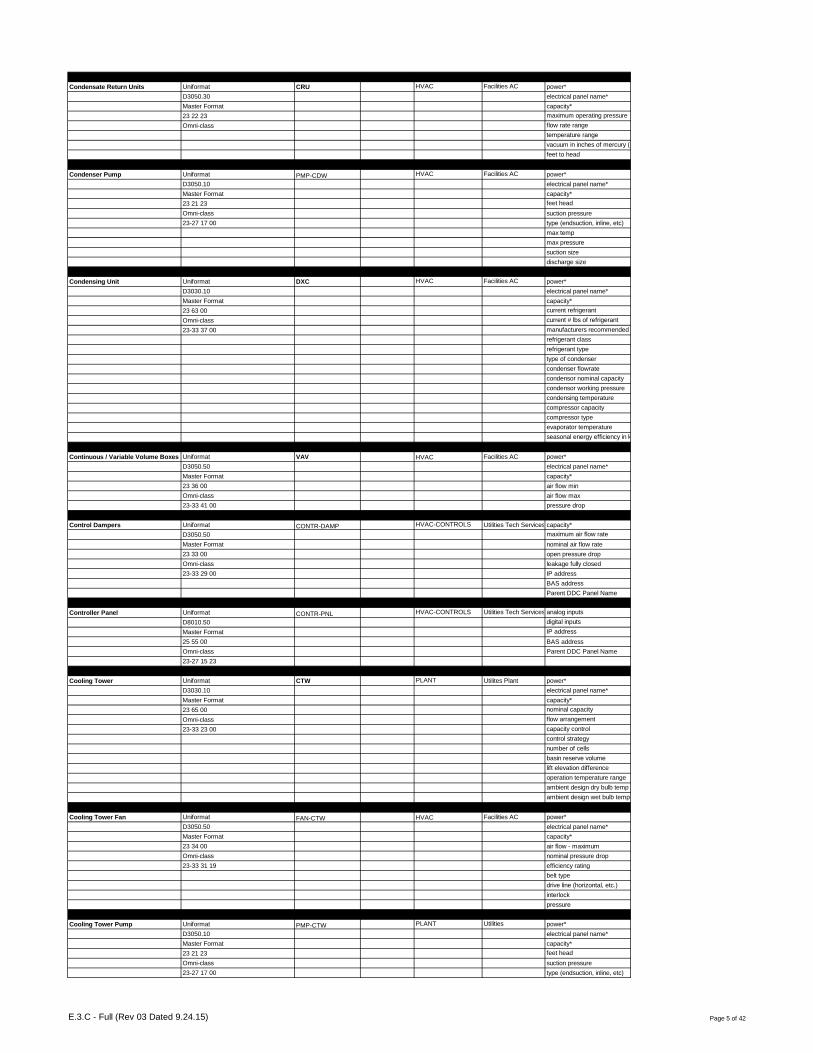
Condensate Return Units Uniformat CRU HVAC Facilities AC power*
D3050.30 electrical panel name*
Master Format capacity*
23 22 23 maximum operating pressure
Omni-class flow rate range
temperature range
vacuum in inches of mercury (hg)
feet to head
Condenser Pump Uniformat PMP-CDW HVAC Facilities AC power*
D3050.10 electrical panel name*
Master Format capacity*
23 21 23 feet head
Omni-class suction pressure
23-27 17 00 type (endsuction, inline, etc)
max temp
max pressure
suction size
discharge size
Condensing Unit Uniformat DXC HVAC Facilities AC power*
D3030.10 electrical panel name*
Master Format capacity*
23 63 00 current refrigerant
Omni-class current # lbs of refrigerant
23-33 37 00 manufacturers recommended charge
refrigerant class
refrigerant type
type of condenser
condenser flowrate
condensor nominal capacity
condensor working pressure
condensing temperature
compressor capacity
compressor type
evaporator temperature
seasonal energy efficiency in kbtu
Continuous / Variable Volume Boxes Uniformat VAV HVAC Facilities AC power*
D3050.50 electrical panel name*
Master Format capacity*
23 36 00 air flow min
Omni-class air flow max
23-33 41 00 pressure drop
Control Dampers Uniformat CONTR-DAMP HVAC-CONTROLS Utilities Tech Services & Facilities ACcapacity*
D3050.50 maximum air flow rate
Master Format nominal air flow rate
23 33 00 open pressure drop
Omni-class leakage fully closed
23-33 29 00 IP address
BAS address
Parent DDC Panel Name
Controller Panel Uniformat CONTR-PNL HVAC-CONTROLS Utilities Tech Services & Facilities ACanalog inputs
D8010.50 digital inputs
Master Format IP address
25 55 00 BAS address
Omni-class Parent DDC Panel Name
23-27 15 23
Cooling Tower Uniformat CTW PLANT Utilites Plant power*
D3030.10 electrical panel name*
Master Format capacity*
23 65 00 nominal capacity
Omni-class flow arrangement
23-33 23 00 capacity control
control strategy
number of cells
basin reserve volume
lift elevation difference
operation temperature range
ambient design dry bulb temp
ambient design wet bulb temp
Cooling Tower Fan Uniformat FAN-CTW HVAC Facilities AC power*
D3050.50 electrical panel name*
Master Format capacity*
23 34 00 air flow - maximum
Omni-class nominal pressure drop
23-33 31 19 efficiency rating
belt type
drive line (horizontal, etc.)
interlock
pressure
Cooling Tower Pump Uniformat PMP-CTW PLANT Utilities power*
D3050.10 electrical panel name*
Master Format capacity*
23 21 23 feet head
Omni-class suction pressure
23-27 17 00 type (endsuction, inline, etc)
E.3.C - Full (Rev 03 Dated 9.24.15) Page 5 of 42

max temp
max pressure
suction size
discharge size
Defibrillator Uniformat EMG SAFETY Risk Management location in space
C1090.60
Master Format
10 43 13
Omni-class
23-25 21 13 19 11
Deionized Water Pumps Uniformat PMP-DIW PLUMB Utilities Water & Facilities Plumbingfilter face velocity
D2060.50 media surface velocity
Master Format pressure drop
22 67 19 particle geometric mean diameter
Omni-class water filter type
23-27 17 00
Dishwasher Uniformat DM FOOD SERVICE Contractors
E1030.80
Master Format
11 48 13
Omni-class
23-31 31 19 11
Distribution Panel Uniformat PNL ELEC Facilities Electric power*
D5020.30 electrical panel name*
Master Format capacity*
26 24 16 main bus current
Omni-class aic rating
23-35 31 13
Domestic Cold Water Pump Uniformat PMP-DOM PLUMB Facilities Plumbing power*
D2010.20 electrical panel name*
Master Format capacity*
22 11 23 feet head
Omni-class suction pressure
23-27 17 00 type (endsuction, inline, etc)
max temp
max pressure
suction size
discharge size
Domestic Hot Water Pump Uniformat PMP-DHW PLUMB Facilities Plumbing power*
D2010.20 electrical panel name*
Master Format capacity*
22 11 23 feet head
Omni-class suction pressure
23-27 17 00 type (endsuction, inline, etc)
max temp
max pressure
suction size
discharge size
Domestic Water Isolation Valves Uniformat VAL-DOM PLUMB Facilities Plumbing & Utilitiescapacity*
D2010.40 valve type
Master Format location in space
22 11 19
Omni-class
23-27 31 00
Door Contact Uniformat SEC-CON SECURITY Access Services
B2050.90
Master Format
08 71 00
Omni-class
23-17 19 11 21 17
Door Position Switch Uniformat SEC-POS SECURITY Access Services
D7010.10
Master Format
28 13 53
Omni-class
23-17 19 11 29 11
E.3.C - Full (Rev 03 Dated 9.24.15) Page 6 of 42

Drinking Fountains & Water Coolers Uniformat DFN PLUMB Facilities Plumbing fountain type
D2010.60
Master Format
22 47 13
Omni-class
23-31 31 00
Drives (VFD, etc.) Uniformat VFD ELEC Utilities Electric & Facilities Electric & Facilities ACpower*
electrical panel name*
Master Format minimum output frequency
40 92 49 maximum output frequency
Omni-class
23-35 17 00
Dumbwaiter - Elevator & Controls Uniformat ELV-DBW CONVEYING Contractor power*
D1010.50 electrical panel name*
Master Format weight limit
14 10 00 speed
Omni-class src hp rating
23-23 17 11 mg motor power
starting amps
accelerating amps
Electric Meter Uniformat METER-ELEC ELEC Facilities Electric meter type
D5020.10 remote reading
Master Format reading ranges
26 16 00 temp range
Omni-class
23-39 23 00
Electrical & Communication Manhole Sump PumpsUniformat PMP-SMP ELEC Utilities Electric & Facilities Electricpower*
D2030.10 electrical panel name*
Master Format capacity*
22 14 29 feet head
Omni-class suction pressure
23-27 17 00 type (endsuction, inline, etc)
max temp
max pressure
suction size
discharge size
max solid size
Electrical Manhole Uniformat MAN-ELEC ELEC Utilities Electric & Facilities Electriclocation in space
G4010.20 GPS location
Master Format
33 71 19
Omni-class
23-17 11 27 23
Electronic Air Cleaner Uniformat FIL-ELE HVAC Facilities AC power*
D3050.50 electrical panel name*
Master Format capacity*
23 43 00 maximum air flow
Omni-class operating temp range
23-27 57 31 operating humidity range
efficiency
replacement filter
initial pressure drop
Elevator Sump Pump Uniformat PMP-SMP CONVEYING Facilities Plumbing power*
D2030.10 electrical panel name*
Master Format capacity*
22 14 29 feet head
Omni-class suction pressure
23-27 17 00 type (endsuction, inline, etc)
max temp
max pressure
suction size
discharge size
max solid size
Emergency Eye Wash Uniformat EMG-EYE SAFETY
D2010.60
Master Format
22 45 16
Omni-class
23-29 37 13
E.3.C - Full (Rev 03 Dated 9.24.15) Page 7 of 42

Emergency Generator Uniformat EMG-GEN ELEC Utilities Electric & Facilities Electric & ITpower*
D5010.10 electrical panel name*
Master Format capacity*
26 32 00 electric generator efficiency
Omni-class gfci capable
23-35 11 00 number of sources
maximum power output
start current factor
fuel type
fuel storage
fuel capacity
operating rpm limits
engine cooling type
engine size
number of batteries
battery capacity
Emergency Lighting Types Uniformat LGT-EMG One type per building (exit signs, emergency common area lights, etc.)ELEC Facilities Electric
D5040.50
Master Format
26 52 00
Omni-class
23-35 47 13
Emergency Shower Uniformat EMG-SHW SAFETY
D2010.60
Master Format
22 45 13
Omni-class
23-29 37 15
Emergency Shower/Eye Wash ComboUniformat EMG-E&S SAFETY Risk Management location in space
D2010.60
Master Format
22 45 00
Omni-class
23-39 37 00
Energy Recovery Unit Uniformat ERU HVAC Facilities AC power*
D3060.60 electrical panel name*
Master Format capacity*
23 72 00 supply fan ext. static pressure
Omni-class supply fan max hp
23-33 55 00 exhaust fan ext static pressure
exaust fan total hp
cfm range
weight
Equipment Disconnects Uniformat EQD One per building ELEC Facilities Electric power*
D5030.00
Master Format
26 28 16
Omni-class
23-35 37 19
Evaporative Cooling Unit Uniformat ECU HVAC Facilities AC power*
D3030.30 electrical panel name*
Master Format capacity*
23 76 00 seasonal energy efficiency in kbtu
Omni-class nominal heat transfer area
23-33 45 13 nominal heat transfer coefficient
evaporator coolant
evaporator temperature range
minimum evaporator flow
maximum evaporator flow
Exhaust Fans Uniformat FAN-EXH HVAC Facilities AC power*
D3060.30 electrical panel name*
Master Format capacity*
23 34 00 air flow - maximum
Omni-class nominal pressure drop
23-33 31 19 efficiency rating
belt type
drive line (horizontal, etc.)
interlock
pressure
Expansion Tanks Uniformat TNK-EXP HVAC Facilities AC capacity*
D3050.10 tank volume
Master Format max system temp
23 00 00 max system pressure
Omni-class
23-27 29 15
E.3.C - Full (Rev 03 Dated 9.24.15) Page 8 of 42

Exterior Art Uniformat ART-EXT One per building (Statues, monuments, etc.)SITE Facilities Maintenance
E2010.10
Master Format
12 10 00
Omni-class
23-21 37 13 11
Exterior Doors Uniformat BXD One per building EGRESS Facilities Maintenance
B2050
Master Format
08 10 00
Omni-class
23-17 11 00
Exterior Signage Uniformat SIGN One per building SITE Facilities Maintenance
G2060.30
Master Format
10 14 00
Omni-class
Fan Coil Units / Blower Coil Units Uniformat FCU HVAC Facilities AC power*
D3020.70 / D3030.70 electrical panel name*
Master Format capacity*
23 82 19 exit static pressure
Omni-class entering air temp db/wb
23-33 33 00 leaving air temp db/wb
entering water temp
leaving water temp
total capacity
sensible capacity
chilled water flow
cooling coil delta P
fan motor hp
filter type
fan type
type of fan drive
fan size (inches)
fan efficiency in % or pf
static pressure in "inches"
Fan Supply - AHU Uniformat FAN-SUP HVAC Facilities AC power*
D3060.10 electrical panel name*
Master Format capacity*
23 34 00 air flow - maximum
Omni-class nominal pressure drop
23-33 31 19 efficiency rating
belt type
drive line (horizontal, etc.)
interlock
pressure
Faucet Uniformat FCT One per building PLUMB Facilities Plumbing
D2010.60
Master Format
22 42 39
Omni-class
23-31 11 00
Filters Uniformat FIL One per building HVAC Facilities AC air flow - maximum
D30 nominal pressure drop
Master Format efficiency rating
23 41 00 belt type
Omni-class drive line (horizontal, etc.)
23-27 57 27 interlock
pressure
Fire & Smoke Dampers Uniformat FIR-DMP FIRE ALARM Util Tech Services
D3050.50
Master Format
23 33 13
Omni-class
23-33 29 11
Fire Alarm Panel Uniformat FIR-PNL FIRE ALARM Util Tech Services power*
D7050.10 electrical panel name*
Master Format
28 31 11
Omni-class
23-29 31 13
E.3.C - Full (Rev 03 Dated 9.24.15) Page 9 of 42

Fire Department Connections Uniformat FIRE-FDC FIRE SUPPRESSION
D4010.10
Master Format
21 11 19
Omni-class
23-29 25 15 19
Fire Extinguishers Uniformat FIR-EXT FIRE SUPPRESSION Facilities Plumbing & Risk Management
D4030.30
Master Format
10 44 16
Omni-class
23-29 25 19
Fire Flow Meters Uniformat METER-FIRE FIRE SUPPRESSION meter type
D4010.90 remote reading
Master Format reading ranges
21 05 19 temp range
Omni-class
23-27 11 15 21
Fire Hydrants Uniformat FIR-HYD FIRE SUPPRESSION
G3010.10
Master Format
33 12 19
Omni-class
23-29 25 13
Fire Indicating Devices Uniformat FIR-IND FIRE ALARM Util Tech Services
D7050.10
Master Format
28 31 63
Omni-class
23-29 31 00
Fire Initiating Devices Uniformat FIR-INI FIRE ALARM Util Tech Services
D7050.10
Master Format
28 31 53
Omni-class
23-29 29 00
Fire Pump Uniformat PMP-FIR FIRE SUPPRESSION power*
D4010.10 electrical panel name*
Master Format capacity*
21 30 00 feet head
Omni-class suction pressure
23-27 17 00 type (endsuction, inline, etc)
max temp
max pressure
suction size
discharge size
Fire Water Valves Uniformat VAL-FIR FIRE SUPPRESSION location in space
D4010.10
Master Format
21 12 23
Omni-class
23-27 31 00
Floor Drain Uniformat DRN-FLR One per building PLUMB Facilities Plumbing
D2020.30
Master Format
22 13 19
Omni-class
23-31 27 00
Floors Uniformat FLO One per building ARCHITECTURAL Custodial
C2030
Master Format
09 60 00
Omni-class
23-15 17 00
Flushometer Valves - Toilet Uniformat VAL-TLT One per building PLUMB Facilities Plumbing
D2010.60
Master Format
22 42 43
Omni-class
23-31 19 15
E.3.C - Full (Rev 03 Dated 9.24.15) Page 10 of 42

Flushometer Valves - Urinal Uniformat VAL-URN One per building PLUMB Facilities Plumbing
D2010.60
Master Format
22 42 43
Omni-class
23-31 21 00
Food Service Range Uniformat KIT-RNG FOOD SERVICE Contractors
E1030.80
Master Format
11 44 13
Omni-class
23-21 21 13 35
Food Service Sinks Uniformat SNK FOOD SERVICE Contractors
D2010.60
Master Format
22 42 16
Omni-class
23-31 13 19 19
Fountains Uniformat FTN PLUMB Facilities Plumbing
IN-F1050.20/EX-G2060.10
Master Format
13 12 00
Omni-class
23-11 29 27
Freezer Uniformat RU FOOD SERVICE Facilities AC & Contractorspower*
E1030.80 electrical panel name*
Master Format capacity*
11 41 26 compressor oil type
Omni-class referigerant type
23-21 21 27 13 compressor type
Freight - Elevator & Controls Uniformat ELV-FRT CONVEYING
D1010.10
Master Format
14 20 00
Omni-class
23-23 11 11
Fresh Air Fans Uniformat FAN-FAF HVAC Facilities AC power*
D3060.40 electrical panel name*
Master Format capacity*
23 34 00 air flow - maximum
Omni-class nominal pressure drop
23-33 31 19 efficiency rating
belt type
drive line (horizontal, etc.)
interlock
pressure
Fresh Air Unit Uniformat FAU HVAC Facilities AC power*
D3060.40 electrical panel name*
Master Format capacity*
23 36 00 air filter type
Omni-class return fan capacity
supply fan capacity
fan ext pressure drop
chilled water rate
coil flow
coil velocity
coil capacity
coil pressure drop
entering air temp db/wb
leaving air temp db/wb
entering water temp
leaving water temp
Fryer Uniformat KIT-FRY FOOD SERVICE Contractors
E1030.80
Master Format
11 44 00
Omni-class
23-21 21 13 21
Fuel Tanks Uniformat TNK-FUEL SITE Facilities access type
D3010.50 storage type
Master Format capacity
23 13 00
Omni-class
23-27 29 19
E.3.C - Full (Rev 03 Dated 9.24.15) Page 11 of 42

Fume Hoods Uniformat FAN-FUF HVAC Utilities Tech Services & Facilities Electricpower*
D3060.30 electrical panel name*
Master Format capacity*
23 38 16 maximum air flow rate
Omni-class temperature range
23-33 31 15 maximum working pressure
termperature rating
nominal air flow rate
open pressure drop
leakage fully closed
Furnaces Uniformat FURN HVAC Facilities AC power*
D3020.10 electrical panel name*
Master Format capacity*
23 54 00 input (BTU/hr)
Omni-class natural gas output
23-33 13 00 LP gas output
AFUE
available AC @.5" ESP
temp rise range
blower speed
no. of burners
Gas Meter Uniformat METER-GAS PLUMB Facilities Plumbing meter type
G3060.10 remote reading
Master Format reading ranges
33 51 33 temp range
Omni-class
23-39 25 00
Gas Regulator Uniformat GAS-REG PLUMB Facilities Plumbing test pressure
G3060.10 working pressure
Master Format flow coefficient
43 13 23 close off rating
Omni-class
23-27 31 47
Gas Systems Uniformat GAS-SYS PLUMB Facilities Plumbing
D2060.30
Master Format
22 63 00
Omni-class
23-39 25 00
Generator Uniformat GEN-SET PLANT Utilities power*
D5010.10 electrical panel name*
Master Format capacity*
26 32 00
Omni-class
23-35 11 00
Graywater System Equipment Uniformat GRAYWATER One per Individual Components (Pumps, Tanks, etc.)PLUMB Facilities Plumbing power*
D2030.60 electrical panel name*
Master Format capacity*
22 13 00
Omni-class
23-39 29 00
Grease Trap Uniformat GRS-TRP PLUMB Facilities Plumbing capacity
D2020.30
Master Format
22 13 19
Omni-class
23-39 33 17 15
Gutters Uniformat ROO-GUT One per building ROOF Facilities Maintenance
B3020.70
Master Format
07 71 23
Omni-class
23-13 41 33
Heat Exchangers - Misc Uniformat HEX HVAC Facilities AC electrical panel name*
D3020.10 capacity*
Master Format exchanger type
23 57 00 dry weight
Omni-class fluid volume
23-27 23 00 max temp
recommended coolant
E.3.C - Full (Rev 03 Dated 9.24.15) Page 12 of 42

Heat Exchangers - Steam Uniformat HEX-STM HVAC Facilities AC power*
D3020.10 electrical panel name*
Master Format capacity*
23 57 00 exchanger type
Omni-class dry weight
23-27 23 00 fluid volume
max temp
recommended coolant
Heat Exchangers - Water Uniformat HEX-WTR HVAC Facilities AC power*
D3020.10 electrical panel name*
Master Format capacity*
23 57 00 exchanger type
Omni-class dry weight
23-27 23 25 fluid volume
max temp
recommended coolant
Heat Pump Uniformat PMP-HEA HVAC Facilities AC power*
D3030.70 electrical panel name*
Master Format capacity*
23 81 43/46 cooling entering fluid temp
Omni-class cooling pressure drop
23-33 17 00 cooling entering air temp
cooling total capacity (mbtuh)
cooling sensible capacity (mbtuh)
cooling heat of rej. (mbtuh)
cooling power input
cooling eer
heating entering fluid temp
heating entering air temp
heating total capacity (mbtuh)
heating heat of abs. (mbtuh)
compressor type
compressor refirgerant charge oz.
Heat Recovery Unit Uniformat ERU-HRU HVAC Facilities AC power*
electrical panel name*
Master Format capacity*
44 67 00 supply fan ext. static pressure
Omni-class supply fan max hp
23-33 11 23 21 exhaust fan ext static pressure
exaust fan total hp
cfm range
weight
Heat Tracing / Anti-Freeze Controls Uniformat HEAT-TRACE PLUMB Facilities Plumbing max pressure
D2010.90 suction size
Master Format discharge size
22 05 33
Omni-class
23-33 15 15 21
Heating Hot Water Pumps Uniformat PMP-HHW HVAC Facilities AC & Utilitiespower*
D3050.10 electrical panel name*
Master Format capacity*
23 21 23 feet head
Omni-class suction pressure
23-27 17 00 type (endsuction, inline, etc)
max temp
max pressure
suction size
discharge size
Heating/Cooling water treatment equipment & tankUniformat TNK-HVAC HVAC Utilities & Facilities ACcapacity*
D3050.10 gallon capacity
Master Format
23 25 00
Omni-class
23-39 33 00
High Voltage Transformer Uniformat HXF exterior transformers (high voltage)ELEC - DISTRIBUTION Utilities Electric power*
G4010.40 electrical panel name*
Master Format
33 73 00
Omni-class
23-35 13 15
High Votage Switches Uniformat HVS ELEC Utilities Electric power*
G4010.50 electrical panel name*
Master Format
33 75 00
Omni-class
23-35 35 00
E.3.C - Full (Rev 03 Dated 9.24.15) Page 13 of 42
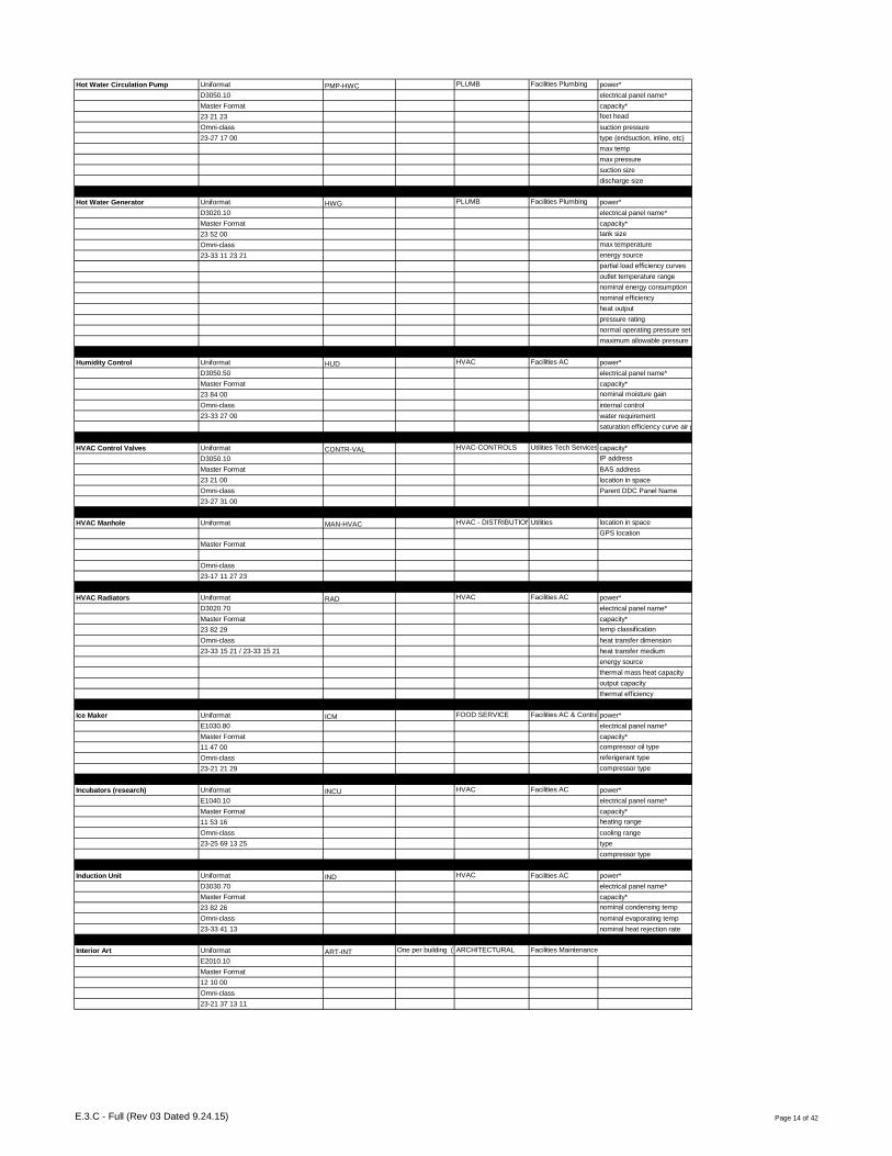
Hot Water Circulation Pump Uniformat PMP-HWC PLUMB Facilities Plumbing power*
D3050.10 electrical panel name*
Master Format capacity*
23 21 23 feet head
Omni-class suction pressure
23-27 17 00 type (endsuction, inline, etc)
max temp
max pressure
suction size
discharge size
Hot Water Generator Uniformat HWG PLUMB Facilities Plumbing power*
D3020.10 electrical panel name*
Master Format capacity*
23 52 00 tank size
Omni-class max temperature
23-33 11 23 21 energy source
partial load efficiency curves
outlet temperature range
nominal energy consumption
nominal efficiency
heat output
pressure rating
normal operating pressure set point
maximum allowable pressure
Humidity Control Uniformat HUD HVAC Facilities AC power*
D3050.50 electrical panel name*
Master Format capacity*
23 84 00 nominal moisture gain
Omni-class internal control
23-33 27 00 water requirement
saturation efficiency curve air pressure drop curve
HVAC Control Valves Uniformat CONTR-VAL HVAC-CONTROLS Utilities Tech Services & Facilities ACcapacity*
D3050.10 IP address
Master Format BAS address
23 21 00 location in space
Omni-class Parent DDC Panel Name
23-27 31 00
HVAC Manhole Uniformat MAN-HVAC HVAC - DISTRIBUTIONUtilities location in space
GPS location
Master Format
Omni-class
23-17 11 27 23
HVAC Radiators Uniformat RAD HVAC Facilities AC power*
D3020.70 electrical panel name*
Master Format capacity*
23 82 29 temp classification
Omni-class heat transfer dimension
23-33 15 21 / 23-33 15 21 heat transfer medium
energy source
thermal mass heat capacity
output capacity
thermal efficiency
Ice Maker Uniformat ICM FOOD SERVICE Facilities AC & Contractorspower*
E1030.80 electrical panel name*
Master Format capacity*
11 47 00 compressor oil type
Omni-class referigerant type
23-21 21 29 compressor type
Incubators (research) Uniformat INCU HVAC Facilities AC power*
E1040.10 electrical panel name*
Master Format capacity*
11 53 16 heating range
Omni-class cooling range
23-25 69 13 25 type
compressor type
Induction Unit Uniformat IND HVAC Facilities AC power*
D3030.70 electrical panel name*
Master Format capacity*
23 82 26 nominal condensing temp
Omni-class nominal evaporating temp
23-33 41 13 nominal heat rejection rate
Interior Art Uniformat ART-INT One per building (Statues, monuments, etc.)ARCHITECTURAL Facilities Maintenance
E2010.10
Master Format
12 10 00
Omni-class
23-21 37 13 11
E.3.C - Full (Rev 03 Dated 9.24.15) Page 14 of 42

Interior Light Fixtures Uniformat LGT-INS One per building ELEC Facilities Electric
D5040.50
Master Format
26 51 00
Omni-class
23-35 47 11
Interior Signage Uniformat SIGN One per building ARCHITECTURAL Facilities Maintenance
C1090.20
Master Format
10 14 00
Omni-class
Irrigation Backflow Preventer Uniformat IRR-BFP IRRIGATION Grounds Irrigation & Facilities Plumbingtype (double check, etc.)
G3010.50
Master Format
33 12 13
Omni-class
23-27 31 11
Irrigation Cisterns & Rainwater Collection with FiltersUniformat IRR-RAIN IRRIGATION Grounds Irrigation & Facilities Plumbing
G3010.50
Master Format
33 47 19
Omni-class
23-27 29 13
Irrigation Controls Uniformat IRR-CON IRRIGATION Grounds Irrigation power*
G2080.10 electrical panel name*
Master Format
32 80 00
Omni-class
Irrigation Flow Sensors Uniformat IRR-FLOW IRRIGATION Grounds Irrigation location in space
G2080.10 GPS location
Master Format
32 80 00
Omni-class
23-27 11 15 23
Irrigation Meter Uniformat METER-IRR IRRIGATION Grounds Irrigation power*
G3010.50 electrical panel name*
Master Format GPS location
33 12 33 location in space
Omni-class meter type
remote reading
reading ranges
temp range
Irrigation Pumps Uniformat PMP-IRR IRRIGATION Grounds Irrigation & Facilities Plumbingpower*
G2080.10 electrical panel name*
Master Format capacity*
32 82 00 feet head
Omni-class suction pressure
23-27 17 00 type (endsuction, inline, etc)
max temp
max pressure
suction size
discharge size
Irrigation Shut-off Valves Uniformat VAL-IRR IRRIGATION Grounds Irrigation location in space
G3010.50 GPS location
Master Format
33 12 16
Omni-class
23-27 31 00
Irrigation Splice Boxes Uniformat IRR-SPLICE IRRIGATION Grounds Irrigation GPS location
G3010.50
Master Format
33 12 00
Omni-class
Irrigation System Uniformat IRR one system asset per buildingIRRIGATION Grounds Irrigation
G2080.10
Master Format
32 80 00
Omni-class
23-11 27 15
E.3.C - Full (Rev 03 Dated 9.24.15) Page 15 of 42
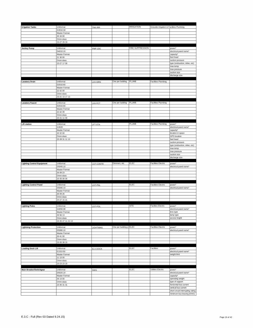
Irrigation Tanks Uniformat TNK-IRR IRRIGATION Grounds Irrigation & Facilities Plumbing
G3010.50
Master Format
33 16 00
Omni-class
23-27 29 19
Jockey Pump Uniformat PMP-JOC FIRE SUPPRESSION power*
D4010.10 electrical panel name*
Master Format capacity*
21 30 00 feet head
Omni-class suction pressure
23-27 17 00 type (endsuction, inline, etc)
max temp
max pressure
suction size
discharge size
Lavatory Drain Uniformat LAV-DRN One per building PLUMB Facilities Plumbing
D2010.60
Master Format
22 42 00
Omni-class
23-31 13 17 13
Lavatory Faucet Uniformat LAV-FCT One per building PLUMB Facilities Plumbing
D2010.60
Master Format
22 42 39
Omni-class
23-31 11 00
Lift station Uniformat LFT-STA PLUMB Facilities Plumbing power*
G3020 electrical panel name*
Master Format capacity*
33 32 00 location in space
Omni-class GPS location
23-39 31 11 13 feet head
suction pressure
type (endsuction, inline, etc)
max temp
max pressure
suction size
discharge size
Lighting Control Equipment Uniformat LGT-CONTR Dimmers, etc. ELEC Facilities Electric power*
D5040.10 electrical panel name*
Master Format
26 09 23
Omni-class
23-35 00 00
Lighting Control Panel Uniformat LGT-PNL ELEC Facilities Electric power*
D5040.10 electrical panel name*
Master Format
26 09 26
Omni-class
23-27 15 21
Lighting Poles Uniformat LGT-POL SITE Facilites Electric power*
G4050.90 electrical panel name*
Master Format lens type
26 56 13 lamp type
Omni-class access height
23-35 47 11 21 13
Lightning Protection Uniformat LIGHTNING One per building per type (emergency, normal power, etc.)ELEC Facilities Electric power*
D5080.10 electrical panel name*
Master Format
26 41 00
Omni-class
23-35 39 15
Loading Dock Lift Uniformat ELV-DOCK ELEC Facilities power*
E1010.50 electrical panel name*
Master Format weight limit
11 13 00
Omni-class
23-23 23 15
Main Breaker/Switchgear Uniformat SWG ELEC Utilities Electric power*
D5020.10 electrical panel name*
Master Format capacity*
26 13 00 operating weight
Omni-class type of support
23-35 31 31 horizontal bus current
vertical bus current
short circuit interrupting rating (KAIC)
minimum bus bracing (KAIC)
E.3.C - Full (Rev 03 Dated 9.24.15) Page 16 of 42

Mechanized Shades Uniformat MOT-SHADE Machine run only ELEC Facilities
E2010.20
Master Format
12 24 00
Omni-class
23-17 21 13 17
Medium & Low Voltage Transformers Uniformat TXF interior transformers (medium & low voltage)ELEC Utilities Electric power*
D5020.10 electrical panel name*
Master Format
26 12 00
Omni-class
23-35 13 17
Misc Emergency Equipment Uniformat EMG SAFETY
E1040.10
Master Format
10 43 00
Omni-class
23-25 21 00
Misc Fans Uniformat FAN HVAC Facilities AC power*
D3050.50 electrical panel name*
Master Format capacity*
23 34 00 air flow - maximum
Omni-class nominal pressure drop
23-33 31 19 efficiency rating
belt type
drive line (horizontal, etc.)
interlock
pressure
Misc Manholes Uniformat MAN MISC Facilities Plumbing, Utilities, Electric
Master Format
Omni-class
23-17 11 27 23
Misc Meters Uniformat METER MISC Facilities Plumbing meter type
G30 remote reading
Master Format reading ranges
33 00 00 temp range
Omni-class
23-39 00 00
Misc Pumps Uniformat PMP MISC Facilities AC, Facilities Plumbing & Utilities
Master Format
Omni-class
23-27 17 00
Misc Tank Uniformat TNK PLUMB Facilities Plumbing
Master Format
Omni-class
23-27 29 00
Motors Uniformat MOT Pumps, Fans, AHUs, etc.HVAC Facilities AC & Facilities Electricpower*
D30 electrical panel name*
Master Format capacity*
23 05 13 HP
Omni-class efficiency
23-35 15 00 drive line (horizontal, etc.)
break horse power in bhp
Oil & Seperator Tanks Uniformat TNK-OIL PLUMB Facilities Plumbing capacity
D2020.30
Master Format
22 13 19
Omni-class
23-39 33 17
Operable Partitions Uniformat MOV-PART ARCHITECTURAL Facilities Maintenance
C1010.50
Master Format
10 22 00
Omni-class
23-15 11 17
Outside Lighting Uniformat LGT-OUT One per building SITE Facilites Electric
G4050.00 attached to facility
Master Format
26 56 00
Omni-class
23-35 47 11 15
E.3.C - Full (Rev 03 Dated 9.24.15) Page 17 of 42

Package Unit Air Conditioner Uniformat DXP HVAC Facilities AC power*
D3050.50 electrical panel name*
Master Format capacity*
23 74 00 nominal condensing temp
Omni-class nominal evaporating temp
23-33 39 19 nominal heat rejection rate
Packaged Terminal Units/ Wall Air Conditioner UnitUniformat PTU HVAC Facilities AC power*
D3030.70 electrical panel name*
Master Format capacity*
23 81 13 nominal condensing temp
Omni-class nominal evaporating temp
23-33 39 19 nominal heat rejection rate
Passenger - Elevator & Controls Uniformat ELV-PAS CONVEYING
D1010.10
Master Format
14 20 00
Omni-class
23-23 11 11
Pressure Reducing Valves & Station Uniformat PRV PLUMB Facilities Plumbing inlet pressure
D2010.40 outlet pressure
Master Format minimum capacity
22 11 19 valve size
Omni-class
23-27 31 47 / 23-27 27 00
Refrigerator Uniformat RU FOOD SERVICE Facilities AC & Contractorspower*
E1030.80 electrical panel name*
Master Format capacity*
11 41 23 compressor oil type
Omni-class referigerant type
23-21 21 27 15 compressor type
Return Air Fan - AHU Uniformat FAN-RAF HVAC Facilities AC power*
D3060.20 electrical panel name*
Master Format capacity*
23 34 00 air flow - maximum
Omni-class nominal pressure drop
23-33 31 19 efficiency rating
belt type
drive line (horizontal, etc.)
interlock
pressure
Reverse Osmosis Pumps Uniformat PMP-ROW PLUMB Utilities Water & Facilities Plumbingfilter face velocity
D2060.50 media surface velocity
Master Format pressure drop
22 67 19 particle geometric mean diameter
Omni-class water filter type
23-27 17 00
Roof Uniformat ROO One per type per building (shingle, metal, foam, etc.)ROOF Facilities Maintenance
B3010.00
Master Format
07 00 00
Omni-class
23-13 39 00
Roof Drain Uniformat ROO-DRN One per building PLUMB Facilities Plumbing & Facilities Maintenance
D2030.30
Master Format
22 14 26
Omni-class
23-13 41 39
Roof scuppers Uniformat ROO-SCUP One per building ROOF Facilities Maintenance
B3020.70
Master Format
07 71 33
Omni-class
23-13 41 11 21
Sanitary Manhole & Storm Manhole Uniformat MAN-PLUMB PLUMB Utilities Water & Facilities PlumbingGPS location
D2020.30/D2030.20
Master Format
22 05 73
Omni-class
23-39 29 11 13 11 / 23-39 29 13 19 15
Sanitary Manhole & Storm Manhole Sump PumpsUniformat PMP-SMP PLUMB Facilities Plumbing power*
D2030.10 electrical panel name*
Master Format capacity*
22 14 29 feet head
Omni-class suction pressure
23-27 17 00 type (endsuction, inline, etc)
max temp
max pressure
suction size
discharge size
max solid size
E.3.C - Full (Rev 03 Dated 9.24.15) Page 18 of 42

Security Cameras Uniformat SEC-CAM SECURITY Access Services
D7030.10
Master Format
28 23 00
Omni-class
23-29 11 00
Control Devices Uniformat CONTR-SENS thermostats, flow indicators, etc.HVAC-CONTROLS Utilities Tech Services & Facilities ACIP address
D8010.50 BAS address
Master Format Parent DDC Panel Name
25 35 16
Omni-class
23-27 11 11 23
Septic Tank Uniformat TNK-SEP PLUMB Facilities Plumbing capacity*
D2020.10 capacity
Master Format inlet size
22 13 53 outlet size
Omni-class
23-27 29 15 15
Sinks Uniformat SNK One per building, unless specialty (surgeons, etc.)PLUMB Facilities Plumbing
D2010.60
Master Format
22 42 16
Omni-class
23-31 13 00
Soil Moisture Sensors Uniformat IRR-MOIST IRRIGATION Grounds Irrigation location in space
G2080.10 GPS location
Master Format
32 80 00
Omni-class
Solar/PV Equipment Uniformat PV-EQUIP ELEC Facilities Electric power*
D5010.30 electrical panel name*
Master Format capacity*
26 31 00 cell type
Omni-class power tolerance
23-35 11 17 number of cells
Special Action Doors Uniformat DOOR-SPEC Mechanical, Overhead, Special Function, etc.EGRESS Facilities Maintenance door type
B2050.40
Master Format
08 30 00
Omni-class
23-17 11 00
Specialty Air Compressor Uniformat ACU-S Engine start, pnuematically controled instrumentation system, black start, etc.PLUMB Facilities Plumbing & Facilities ACpower*
D2050 electrical panel name*
Master Format capacity*
22 15 00 has hot gas bypass
Omni-class ideal capacity
23-27 21 00 nominal capacity
max pressure
compressor type
Stage Lift - Elevator & Controls Uniformat ELV-STG CONVEYING
D1010.20
Master Format
14 43 00
Omni-class
23-23 13 11 19
Steam Isolation Valves Uniformat VAL-STM PLUMB Facilities Plumbing & Utilitieslocation in space
D3050.30 GPS location
Master Format valve type
23 22 16
Omni-class
23-27 31 00
Steam Traps Uniformat STM-TRP PLUMB Facilities AC & Facilities Plumbingmaximum operating pressure
D3050.30 water inlet temperature range
Master Format flow coefficient
23 22 00
Omni-class
23-27 37 15
Strainer Uniformat STR PLUMB Facilities Plumbing
D20
Master Format
22 00 00
Omni-class
23-27 55 29
Surge Protectors Uniformat TVSS Facility System Surge Protectors only; not communicaiton or IT room Surge ProtectorsELEC Utilities Electric & Facilities Electric & ITpower*
D5080.70 electrical panel name*
Master Format max allowed voltage drop
26 43 00 net impendance
Omni-class
23-35 39 17
E.3.C - Full (Rev 03 Dated 9.24.15) Page 19 of 42

Switchboards & Panelboards Uniformat PNL ELEC Facilities Electric power*
D5020.30 electrical panel name*
Master Format capacity*
26 24 00 main bus current
Omni-class aic rating
23-35 31 29
Trash Compactor Uniformat TRSH-COM SITE Facilities
E1090.10
Master Format
11 82 26
Omni-class
23-27 59 15 19
Unit Heater Uniformat FAN-UNH HVAC power*
D3020.70 electrical panel name*
Master Format capacity*
23 82 39 temp rise
Omni-class
23-33 15 00
UPS System Uniformat UPS Facility System UPS only; not communicaiton or IT room UPSELEC Facilities Electric power*
D5010.20 electrical panel name*
Master Format supply voltage
26 33 53 supply voltage offset
Omni-class connected conductor function
23-35 23 21
Vacuum Pump Uniformat PMP-VAC PLUMB Facilities Plumbing & Facilities ACpower*
D2060.20 electrical panel name*
Master Format capacity*
22 62 19 max vacuum
Omni-class head
23-27 17 00 pump type
Waste Disposal Uniformat KIT-WSD FOOD SERVICE Contractors
D2010.60
Master Format
22 42 26
Omni-class
23-21 21 21
Waste Ejector Pump Uniformat PMP-WEP PLUMB Facilities Plumbing power*
D2020.10 electrical panel name*
Master Format capacity*
22 13 36 feet head
Omni-class suction pressure
23-27 17 35 type (endsuction, inline, etc)
max temp
max pressure
suction size
discharge size
max solid size
Water Heater Uniformat WTR-HTR PLUMB Utilities Water & Facilities Plumbingpower*
D2010.20 electrical panel name*
Master Format capacity*
22 33 00 / 22 34 00 flow rate recovery at 100˚
Omni-class storage capacity
23-31 29 00 steam supply entering coil pressure
entering water temp
leaving water temp
Water Meter Uniformat METER-WATER PLUMB Utilities Water & Facilities Plumbingmeter type
G3010.10 remote reading
Master Format reading ranges
33 12 33 temp range
Omni-class
23-39 27 00
Water Purificaiton - Deionized Uniformat WTR-DI PLUMB Facilities Plumbing, Utilitiesfilter face velocity
D2060.50 media surface velocity
Master Format pressure drop
22 67 19 particle geometric mean diameter
Omni-class water filter type
23-27 55 21
Water Purification - Reverse OsmosisUniformat WTR-RO PLUMB Utilities Water & Facilities Plumbingpower*
D2060.50 electrical panel name*
Master Format capacity*
22 67 19 initial resistance
Omni-class final resistance
23-39 41 13 15 flow rate range
filter face velocity
media surface velocity
pressure drop
particle geometric mean diameter
water filter type
E.3.C - Full (Rev 03 Dated 9.24.15) Page 20 of 42

Water Softener Uniformat WS PLUMB Utilities Water power*
D2010.20 capacity*
Master Format
22 31 00
Omni-class
23-27 55 27 11
Wheelchair/Personal Lift - Elevator & ControlsUniformat ELV-WCH CONVEYING
D1010.20
Master Format
14 42 00
Omni-class
23-23 13 11 25
E.3.C - Full (Rev 03 Dated 9.24.15) Page 21 of 42

Asset Group DescriptionCOBie "Type
Category"System Type
Interior ArtART-INT ARCHITECTURAL
One per
building
Ceiling TileCLG-TIL ARCHITECTURAL
One per
building
FloorsFLO ARCHITECTURAL
One per
building
Operable Partitions MOV-PART ARCHITECTURAL
Dumbwaiter - Elevator & Controls ELV-DBW CONVEYING
Freight - Elevator & Controls ELV-FRT CONVEYING
Passenger - Elevator & Controls ELV-PAS CONVEYING
Stage Lift - Elevator & Controls ELV-STG CONVEYING
Wheelchair/Personal Lift - Elevator & Controls ELV-WCH CONVEYING
Exterior DoorsBXD EGRESS
One per
building
Special Action Doors DOOR-SPEC EGRESS
ADA Doors & Openers ADA ELEC
Automatic Transfer Switch ATS ELEC
Battery Systems BES ELEC
Automatic Doors DOOR-AUTO ELEC
Loading Dock Lift ELV-DOCK ELEC
Emergency Generator EMG-GEN ELEC
Equipment DisconnectsEQD ELEC
One per
building
High Votage Switches HVS ELEC
Lighting Control EquipmentLGT-CONTR ELEC
Dimmers,
etc.
Emergency Lighting Types
LGT-EMG ELEC
One type
per
building
Interior Light FixturesLGT-INS ELEC
One per
building
Lighting Control Panel LGT-PNL ELEC
Lightning Protection
LIGHTNING ELEC
One per
building
per type
Communication Manhole MAN-COM ELEC
Electrical Manhole MAN-ELEC ELEC
Electric Meter METER-ELEC ELEC
Mechanized ShadesMOT-SHADE ELEC
Machine
run only
Sanitary Manhole & Storm Manhole Sump Pumps PMP-SMP ELEC
Distribution Panel PNL ELEC
Switchboards & Panelboards PNL ELEC
Solar/PV Equipment PV-EQUIP ELEC
Main Breaker/Switchgear SWG ELEC
Surge Protectors TVSS ELEC Not IT
Medium & Low Voltage Transformers TXF ELEC
UPS System UPS ELEC Not IT
Drives (VFD, etc.) VFD ELEC
High Voltage Transformer HXF ELEC - DISTRIBUTION
Annunciators FIR-ANNUNC FIRE ALARM
Fire & Smoke Dampers FIR-DMP FIRE ALARM
E.3.C - Summarized (Rev 03 Dated 9.24.15) Page 1 of 5
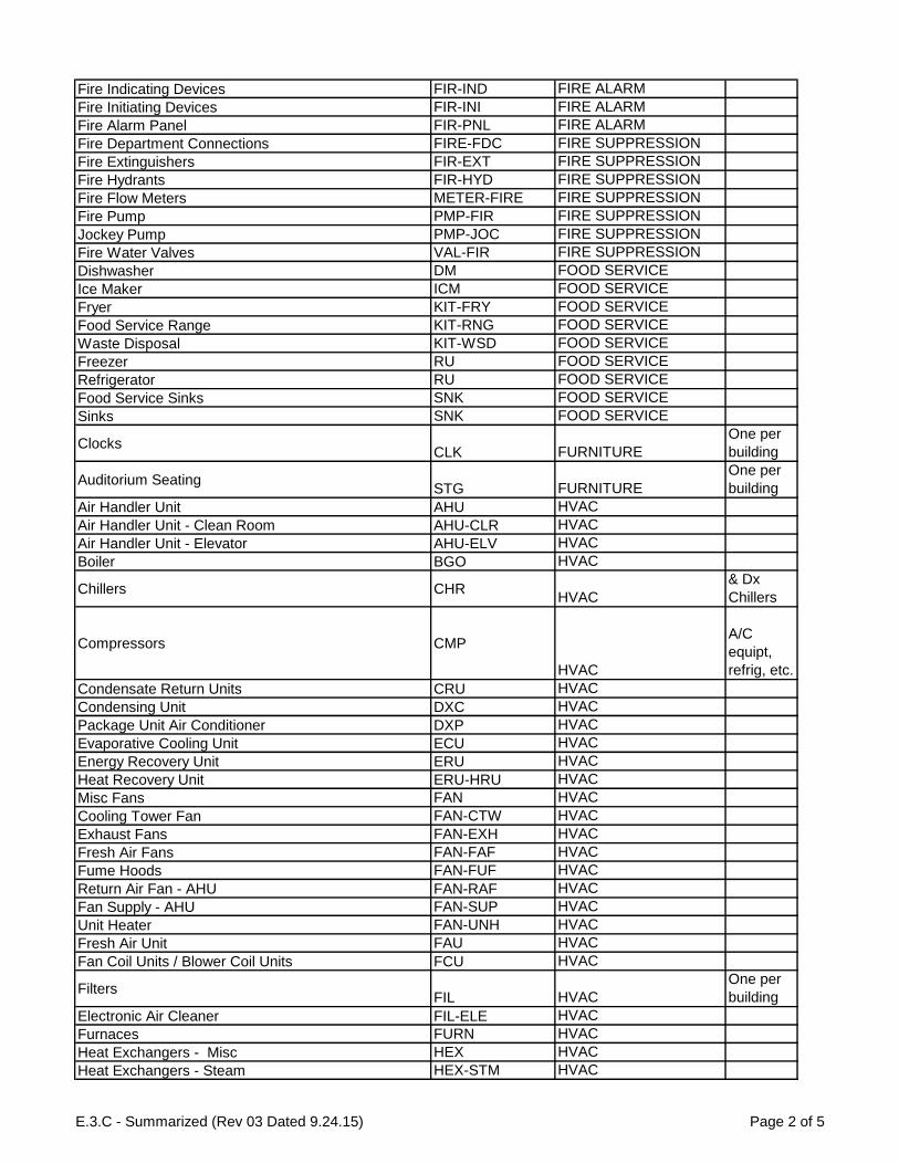
Fire Indicating Devices FIR-IND FIRE ALARM
Fire Initiating Devices FIR-INI FIRE ALARM
Fire Alarm Panel FIR-PNL FIRE ALARM
Fire Department Connections FIRE-FDC FIRE SUPPRESSION
Fire Extinguishers FIR-EXT FIRE SUPPRESSION
Fire Hydrants FIR-HYD FIRE SUPPRESSION
Fire Flow Meters METER-FIRE FIRE SUPPRESSION
Fire Pump PMP-FIR FIRE SUPPRESSION
Jockey Pump PMP-JOC FIRE SUPPRESSION
Fire Water Valves VAL-FIR FIRE SUPPRESSION
Dishwasher DM FOOD SERVICE
Ice Maker ICM FOOD SERVICE
Fryer KIT-FRY FOOD SERVICE
Food Service Range KIT-RNG FOOD SERVICE
Waste Disposal KIT-WSD FOOD SERVICE
Freezer RU FOOD SERVICE
Refrigerator RU FOOD SERVICE
Food Service Sinks SNK FOOD SERVICE
Sinks SNK FOOD SERVICE
ClocksCLK FURNITURE
One per
building
Auditorium SeatingSTG FURNITURE
One per
building
Air Handler Unit AHU HVAC
Air Handler Unit - Clean Room AHU-CLR HVAC
Air Handler Unit - Elevator AHU-ELV HVAC
Boiler BGO HVAC
Chillers CHRHVAC
& Dx
Chillers
Compressors CMP
HVAC
A/C
equipt,
refrig, etc.
Condensate Return Units CRU HVAC
Condensing Unit DXC HVAC
Package Unit Air Conditioner DXP HVAC
Evaporative Cooling Unit ECU HVAC
Energy Recovery Unit ERU HVAC
Heat Recovery Unit ERU-HRU HVAC
Misc Fans FAN HVAC
Cooling Tower Fan FAN-CTW HVAC
Exhaust Fans FAN-EXH HVAC
Fresh Air Fans FAN-FAF HVAC
Fume Hoods FAN-FUF HVAC
Return Air Fan - AHU FAN-RAF HVAC
Fan Supply - AHU FAN-SUP HVAC
Unit Heater FAN-UNH HVAC
Fresh Air Unit FAU HVAC
Fan Coil Units / Blower Coil Units FCU HVAC
FiltersFIL HVAC
One per
building
Electronic Air Cleaner FIL-ELE HVAC
Furnaces FURN HVAC
Heat Exchangers - Misc HEX HVAC
Heat Exchangers - Steam HEX-STM HVAC
E.3.C - Summarized (Rev 03 Dated 9.24.15) Page 2 of 5

Heat Exchangers - Water HEX-WTR HVAC
Humidity Control HUD HVAC
Incubators (research) INCU HVAC
Induction Unit IND HVAC
Motors
MOT HVAC
Pumps,
Fans,
AHUs,
etc.
Condenser Pump PMP-CDW HVAC
Chilled Water Pump PMP-CHW HVAC
Heat Pump PMP-HEA HVAC
Heating Hot Water Pumps PMP-HHW HVAC
Chilled Water Pump - Special Process PMP-SP HVAC
Packaged Terminal Units/ Wall Air Conditioner Unit PTU HVAC
HVAC Radiators RAD HVAC
Chilled Water Expansion Tank TNK-CHW HVAC
Expansion Tanks TNK-EXP HVAC
Heating/Cooling water treatment equipment & tank TNK-HVAC HVAC
Chilled/Heating Water Isolation Valves VAL-HVAC HVAC
Continuous / Variable Volume Boxes VAV HVAC
HVAC Manhole MAN-HVAC HVAC - DISTRIBUTION
Control Dampers CONTR-DAMP HVAC-CONTROLS
Control Devices
CONTR-DEV HVAC-CONTROLS
One per
type per
building
Controller Panel CONTR-PNL HVAC-CONTROLS
HVAC Control Valves CONTR-VAL HVAC-CONTROLS
Irrigation System
IRR IRRIGATION
one
system
asset per
building
Irrigation Backflow Preventer IRR-BFP IRRIGATION
Irrigation Controls IRR-CON IRRIGATION
Irrigation Flow Sensors IRR-FLOW IRRIGATION
Soil Moisture Sensors IRR-MOIST IRRIGATION
Irrigation Cisterns & Rainwater Collection with Filters IRR-RAIN IRRIGATION
Irrigation Splice Boxes IRR-SPLICE IRRIGATION
Irrigation Meter METER-IRR IRRIGATION
Irrigation Pumps PMP-IRR IRRIGATION
Irrigation Tanks TNK-IRR IRRIGATION
Irrigation Shut-off Valves VAL-IRR IRRIGATION
Misc Manholes MAN MISC
Misc Meters METER MISC
Misc Pumps PMP MISC
Chiller Compressor CMP-CHR PLANT
Cooling Tower CTW PLANT
Generator GEN-SET PLANT
Boiler Feedwater Pump PMP-BFW PLANT
Condensate Pumps PMP-CON PLANT
Cooling Tower Pump PMP-CTW PLANT
Air Compressor ACU PLUMB
Specialty Air Compressor ACU-S PLUMB
Air Dryer ADY PLUMB
Backflow Preventor BFP PLUMB
Cisterns CISTERN PLUMB
E.3.C - Summarized (Rev 03 Dated 9.24.15) Page 3 of 5
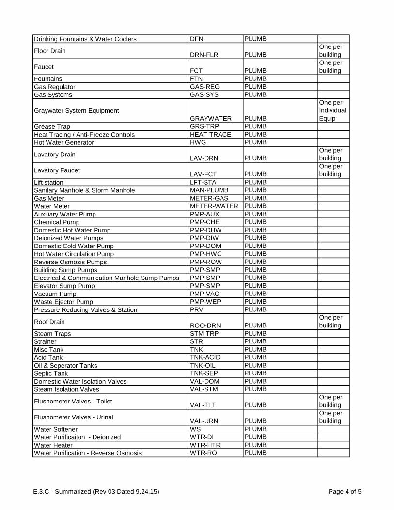
Drinking Fountains & Water Coolers DFN PLUMB
Floor DrainDRN-FLR PLUMB
One per
building
FaucetFCT PLUMB
One per
building
Fountains FTN PLUMB
Gas Regulator GAS-REG PLUMB
Gas Systems GAS-SYS PLUMB
Graywater System Equipment
GRAYWATER PLUMB
One per
Individual
Equip
Grease Trap GRS-TRP PLUMB
Heat Tracing / Anti-Freeze Controls HEAT-TRACE PLUMB
Hot Water Generator HWG PLUMB
Lavatory DrainLAV-DRN PLUMB
One per
building
Lavatory FaucetLAV-FCT PLUMB
One per
building
Lift station LFT-STA PLUMB
Sanitary Manhole & Storm Manhole MAN-PLUMB PLUMB
Gas Meter METER-GAS PLUMB
Water Meter METER-WATER PLUMB
Auxiliary Water Pump PMP-AUX PLUMB
Chemical Pump PMP-CHE PLUMB
Domestic Hot Water Pump PMP-DHW PLUMB
Deionized Water Pumps PMP-DIW PLUMB
Domestic Cold Water Pump PMP-DOM PLUMB
Hot Water Circulation Pump PMP-HWC PLUMB
Reverse Osmosis Pumps PMP-ROW PLUMB
Building Sump Pumps PMP-SMP PLUMB
Electrical & Communication Manhole Sump Pumps PMP-SMP PLUMB
Elevator Sump Pump PMP-SMP PLUMB
Vacuum Pump PMP-VAC PLUMB
Waste Ejector Pump PMP-WEP PLUMB
Pressure Reducing Valves & Station PRV PLUMB
Roof DrainROO-DRN PLUMB
One per
building
Steam Traps STM-TRP PLUMB
Strainer STR PLUMB
Misc Tank TNK PLUMB
Acid Tank TNK-ACID PLUMB
Oil & Seperator Tanks TNK-OIL PLUMB
Septic Tank TNK-SEP PLUMB
Domestic Water Isolation Valves VAL-DOM PLUMB
Steam Isolation Valves VAL-STM PLUMB
Flushometer Valves - ToiletVAL-TLT PLUMB
One per
building
Flushometer Valves - UrinalVAL-URN PLUMB
One per
building
Water Softener WS PLUMB
Water Purificaiton - Deionized WTR-DI PLUMB
Water Heater WTR-HTR PLUMB
Water Purification - Reverse Osmosis WTR-RO PLUMB
E.3.C - Summarized (Rev 03 Dated 9.24.15) Page 4 of 5

Roof
ROO ROOF
One per
type per
building
(shingle,
metal,
foam,
etc.)
GuttersROO-GUT ROOF
One per
building
Roof scuppersROO-SCUP ROOF
One per
building
Carbon Monoxide DetectorCMD SAFETY
One per
building
Defibrillator EMG SAFETY
Misc Emergency Equipment EMG SAFETY
Emergency Shower/Eye Wash Combo EMG-E&S SAFETY
Emergency Eye Wash EMG-EYE SAFETY
Emergency Shower EMG-SHW SAFETY
Blue Lights & Phones ECB SECURITY
Burglar Alarm SEC-ALM SECURITY
Security Cameras SEC-CAM SECURITY
Card Readers SEC-CARD SECURITY
Door Contact SEC-CON SECURITY
Door Position Switch SEC-POS SECURITY
Exterior ArtART-EXT SITE
One per
building
Outside LightingLGT-OUT SITE
One per
building
Lighting Poles LGT-POL SITE
Exterior SignageSIGN SITE
One per
building
Interior SignageSIGN SITE
One per
building
Fuel Tanks TNK-FUEL SITE
Trash Compactor TRSH-COM SITE
E.3.C - Summarized (Rev 03 Dated 9.24.15) Page 5 of 5

CONSTRUCTION STANDARDS GUIDELINES
Revised Jan-15 A/E Deliverables-2.02
Exhibit 3.D - FM Model Criteria
A valuable part of the BIM process, models provide opportunity to improve communication during
planning, design, construction, and operations. Outstanding implications exist for the use of models
in facilities management; however, model integration is not currently a common management tool at
Texas State University (TXST). Desiring to always improve, TXST is committed to the innovative use
of tools such as models that help staff to better steward facilities. A continued improvement of
operational workflows is an expected result from the use of model deliverables.
The intent of this section is to include the minimum criteria for 3D models as they relate to the BIM
for FM Deliverables alone. This section does not replace or lessen modeling criteria in other sections
of TXST specifications or contract requirements related to other BIM Use Cases (applications of BIM
for other objectives).
Native Files from As-Built / Field Coordinated Model
The construction contractor shall provide two versions of the native files that support the as-built /
field coordinated model at multiple times before project closeout and at substantial completion.
These files are the model instances that build the federated coordination models. One version shall
be the native files saved from the design / trade software it was created in. The other version shall
be the interoperable / sharing formats from the design / trade software it was created in. Examples
of interoperable formats include: LandXML, gbXML, DWG, ASCII, etc. The intent for design / trade
files and interoperable formats is to allow opportunities for integration in future design work,
allowing for record update with field changes, and much more.
FM Model
The construction contractor shall provide two versions of the as-built / field coordinated model in
re-savable NWD format at multiple times before close-out (per the BIM Execution Plan) and at
substantial completion of the project. As-built models shall at a minimum include all components
represented in the COBie deliverable for spaces and components (named equipment). Exception to
this shall be all building level assets (clocks, seating, faucets, etc.), fire initiating and indicating
devices, and BAS sensors.
One version of the NWD provided model shall be the final as-built model per the field coordination
effort.
The second version of the NWD model shall be optimized (stripped down and lightweight) for
Facilities Management use. Optimization shall allow for easy navigation and viewing of assets.
Particular optimization shall include, but not be limited to, ceilings at fifty percent transparency and
the hiding of all doors. Also, included shall be the unique color-coding of all building systems
(electrical, chilled water, heating water, domestic water, etc.) per the current TXST coloring schema.
The coloring schema shall be documented in the BIM Execution Plan as well.

CONSTRUCTION STANDARDS GUIDELINES
Revised Jan-15 A/E Deliverables-2.02
Each component in COBie shall have a minimum of one saved viewpoint in the model. Exception to
this shall be all building level assets (clocks, seating, faucets, etc.), fire initiating and indicating
devices, and BAS sensors. These saved viewpoint files shall be attached to the component in the
documents portion of the COBie file.


![Development of BIM Execution Plan for BIM Model …...information system (GIS)-based FM system. Lin et al. [12] proposed a mobile automated BIM-based facility management (BIMFM) system](https://img.pdfslide.net/doc/110x75/5f5355582cc3004cb219b75f/development-of-bim-execution-plan-for-bim-model-information-system-gis-based.jpg)