Embed Size (px)
Citation preview

CITY AND COUNTY OF SAN FRANCISCO Attachment B, Bid Ad. No. 01 ITSF14000283/CD
RQMT14000042
Budget #s: MT14108N & MT14109N
MSF60 CABINET ASSEMBLY SPECIFICATION Dated 12-17-2013
Page 1 of 31
SECTION 1 – GENERAL EQUIPMENT SPECIFICATIONS: 1
2 SPECIFICATION OUTLINE: 3 The following specifications are for MSF60 Cabinet Assembly. The specifications are 4 divided into five complete sections. The First Section outlines the overall specification 5 requirements. The Second Section details the MSF Cabinet Assembly. The Third 6 Section details Shipping. The Forth Section details Warranty and Support. The Fifth 7 Section details supporting Tables and Drawings attached in PDF format. The MSF60 8 Cabinet shall be delivered complete with all equipment and accessories necessary for 9 safe and efficient operation. 10 The MSF60 Cabinet shall be ready for immediate job site operation within the City and 11 County of San Francisco. The MSF60 Cabinet shall comply with NEMA Standards 12 Publication TS2-2003 v02.06. 13 14 MANUFACTURING, MATERIAL AND DESIGN PRACTICES: 15 It is intended that the manufacturer, in the selection of components will use material and 16 design practices that are the best available in the industry for the type of operating 17 conditions to which the unit will be subjected. All MSF60 Cabinet parts, equipment and 18 accessories shall conform in strength, quality of material and workmanship to 19 recognized industry standards. 20 21 ALTERNATES: 22 When the name of a manufacturer, brand or make, with or without model number, is 23 used in describing any item in this specification, bids for similar articles will be 24 considered unless otherwise stated. Bidders may also propose items of equivalent 25 features or manufacturer’s updated part or part number. Purchasing shall be the sole 26 judge as to whether such alternate articles are acceptable. Unless bidder states to the 27 contrary, articles offered will be assumed to be the specific article named in this 28 specification. If not offering the specific article named, bidder should enclose with its bid, 29 full information, specifications and descriptive data on items offered. Purchasing 30 reserves the right to permit deviations from the specifications if any article offered is 31 substantially in accord with Purchasing’s specifications and is deemed by Purchasing to 32 be of as good quality and as fully satisfactory for its intended use, Bidder is responsible 33 for identifying any deviations from Purchasing’s specifications. Bidders should not 34 assume an alternate offered is an approved equal. The City will evaluate the alternate 35 and inform the bidder if the alternate is acceptable. Purchasing must approve all 36 alternates. 37 38 39

CITY AND COUNTY OF SAN FRANCISCO Attachment B, Bid Ad. No. 01 ITSF14000283/CD
RQMT14000042
Budget #s: MT14108N & MT14109N
MSF60 CABINET ASSEMBLY SPECIFICATION Dated 12-17-2013
Page 2 of 31
GENERALITIES: 40 To allow for manufacturer’s specific designs, and insure a level of competitiveness, we 41 have left certain areas of our specifications general by design. In such cases, the items 42 being referred to may be general, but adherence to the requested end product and /or 43 result must be met. This is especially important in areas where critical dimensions, 44 capacities, grades of steel, etc. are specified. In the cases where the word SHALL is 45 used, no substitution will be allowed. 46
47 APPLICABLE DOCUMENTS AND CERTIFICATIONS: 48 Specifications on the following pages are written with the intent to comply with all 49 applicable documents and certifications, but the final responsibility to comply shall rest 50 with the vendor and not the City and County of San Francisco. The successful bidder 51 shall adhere to the standards set forth by the following agency: 52 53
NEMA Standards Publication TS2- 2003 v02.06.0 54
UL 3R Certification 55 56 DEMONSTRATIONS 57 The City reserves the option to request, and the bidder shall agree to provide, an “on 58 the job demonstration and evaluation” for the City’s Traffic Signal Shop personnel 59 before acceptance of contract in the event performance of unit proposed is not familiar 60 to the City. If requested by the City, a demonstrator unit shall be made available prior to 61 award and provided at no additional cost to the City. Time and amount of hours 62 required for such evaluation shall be as determined by the City. 63 64 WIRING ROUTING AND HARDWARE REQUIREMENTS: 65 All wiring shall have adequate protective covers wherever there is a possibility of 66 contact with any other components. Separators shall be used where applicable. No 67 tape or adhesive fasteners will be accepted. All wiring shall be routed to be clear of all 68 heat sources and shall be protected from any present or potential source of snags, 69 abrasions or sharp edges. 70 71 DELIVERY REQUIREMENTS: 72 We are setting the delivery schedule at not more than 60 calendar days. This unit 73 should be delivered and be ready for service within the stated time range. If the MSF60 74 Cabinet being bid meets all other requirements of the specification, but cannot meet the 75 specified time allotted for delivery, this discrepancy shall be stated upon the bid return. 76 77

CITY AND COUNTY OF SAN FRANCISCO Attachment B, Bid Ad. No. 01 ITSF14000283/CD
RQMT14000042
Budget #s: MT14108N & MT14109N
MSF60 CABINET ASSEMBLY SPECIFICATION Dated 12-17-2013
Page 3 of 31
CONTRACT AMENDMENT: 78 Any changes made to the specifications after the order is issued shall be approved by 79
the Purchaser prior to the incorporation of the changes. Any work performed prior to 80
the City’s issuance of a written amendment to the order will be done at the risk of the 81
vendor with the possibility of delayed acceptance and payment of the cabinets. 82
83
BIDDER’S QUALIFICATIONS Not used in Technical Specification 84 Performance testing of a sample cabinet assembly shall be required by the SFMTA 85 Traffic Signal Shop following contract award. If the sample cabinet fails to meet 86 standard practice workmanship, the units shall be rejected. 87 88 Purchasing reserves the right, when evaluating bids, to consider factors other than bid 89 prices. Such factors include but are not limited to: 90
The manufacturer’s track record for meeting the specifications below, especially 91 in regards to workmanship and on-time delivery. 92
Adequacy of bidder's service department (equipment and personnel) where 93 support would be provided and where warranty and other repair work would be 94 performed. 95
96 If successful bidder is not the manufacturer, bidder shall furnish a manufacturer's 97 written guarantee that the manufacturer's warranty and service will be passed on to the 98 City. 99 100

CITY AND COUNTY OF SAN FRANCISCO Attachment B, Bid Ad. No. 01 ITSF14000283/CD
RQMT14000042
Budget #s: MT14108N & MT14109N
MSF60 CABINET ASSEMBLY SPECIFICATION Dated 12-17-2013
Page 4 of 31
BIDDER’S COMPLIANCE AND EXCEPTIONS 101 All exceptions shall be stated no matter how seemingly minor. Bidders shall 102
indicate compliance with each section and line item specifications as required, in 103
the line spaces provided by marking with a “Y” for yes. If the bidder is offering 104
an alternate of equal or superior status to the line item specification, bidder will 105
indicate by marking with an “E” for exception on each line item. The bidder must 106
then reference each item exception and explain the exception taken and the 107
proposed alternate on the Bid Exception Sheets. 108
109
**Bids which do not include confirmation of each section and line item as 110
required, will be deemed to take exception to such bid requirements, which may 111
result in the bid being deemed non-responsive. If exceptions are taken, Bid 112
Exception Sheets must be returned with the submitted bids. 113
114
IMPORTANT: If a single vendor is submitting multiple bids, the vendor shall 115
submit a completed set of specs for each individual bid. Multiple bids that are 116
submitted as one bid package will not be acceptable. 117
118

CITY AND COUNTY OF SAN FRANCISCO Attachment B, Bid Ad. No. 01 ITSF14000283/CD
RQMT14000042
Budget #s: MT14108N & MT14109N
MSF60 CABINET ASSEMBLY SPECIFICATION Dated 12-17-2013
Page 5 of 31
Section 2 – PRODUCTS 119
120 DESCRIPTION: 121 This specification describes the MSF60 Cabinet, a cabinet that meets design and 122 operation standards for the City and County of San Francisco Municipal Transportation 123 Agency (SFMTA). The cabinet is to house and operate with a 2070 LXN2 controller, 124 and shall also be able to house and operate with a NEMA TS 2 Type 1 controller. 125 126 This specification is for the cabinet only. The 2070 LXN2 controller will be provided 127 from other sources. 128 129 GENERAL BID ITEM: 130 131 MSF60 Cabinet Assembly, per this specification and bid packet. 132 133 MSF60 CABINET ASSEMBLY, DETAILED ITEM DESCRIPTIONS 134 _____ All Cabinets shall be manufactured to the NEMA Standards Publication TS2- 135
2003 v02.06. 136 _____ The traffic signal controller cabinet shall be NEMA TS 2 Type 1. The TS 2 Type 137
1 cabinets provided in this contract shall be 100% compatible with type 2070 138 LXN2 controllers as described in the March 12, 2009 Caltrans Transportation 139 Electrical Equipment Specifications (TEES). 140
_____ The TS 2 Type 1 cabinet assembly provided in this contract shall accept both 141 2070 and NEMA TS 2 Type 1 controllers built by other manufacturers that 142 conform to the 2070 and NEMA specifications respectively. All necessary data 143 shall be transferred between controller and cabinet. SFMTA will not accept 144 hybrid non-standard solutions. 145
146 The MSF60 Cabinet assembly shall meet the following additional requirements: 147 _____ Cabinet wiring and cabinet layout diagrams shall be provided as follows: 148
Two printed sets, folded to finished size of 8 ½” X 11”. 149
On Compact Disk or USB Flash Drive in CAD and PDF format. 150 _____ Cabinets shall be equipped with a sliding computer shelf with built in document 151
storage compartment. (See detail drawings MSF60 CABINET BOTTOM SHELF 152 LAPTOP SHELF-DRAWER in Section 5, Line 587 on Page 21. 153
_____ See Section 5, Line 602 on Page 25 for Cabinet Layout details. 154 _____ The cabinet shall be designed to mount on an M-SF concrete controller 155
foundation as illustrated on Section 5, Line 579 on Page 19. 156 157

CITY AND COUNTY OF SAN FRANCISCO Attachment B, Bid Ad. No. 01 ITSF14000283/CD
RQMT14000042
Budget #s: MT14108N & MT14109N
MSF60 CABINET ASSEMBLY SPECIFICATION Dated 12-17-2013
Page 6 of 31
Wiring and Equipment Layout 158 _____ Equipment and auxiliary panels shall be installed as per Cabinet Layout drawing 159
on Section 5, Line 602 on Page 25. 160 _____ Cabinet shall be wired and labeled as per wiring diagram on Section 5, Line 598 161
on page 24. Wiring and terminals shall be labeled as illustrated on wiring 162 diagram. 163
164 Enclosure: (See drawings in Section 5, Line 598/603/609 on pages 24, 25 and 26) 165 _____ The cabinet shall be weatherproof and shall meet UL 3R enclosure specification. 166 _____ Enclosure shall be 0.125" aluminum. 167 _____ Dimensions shall be as follows: 168
169
MSF60
External
Height – “Front / Back” 61” / 60”
Width 36”
Depth(with doors) 18 ½”
Door Opening Height (Minimum) 51”
Width (Minimum) 33 5/8”
Base Flange (See Page 19)
Front and Back 3”
Sides 3 1/2 “
170 _____ Four anchor bolt holes slotted in the base flange: diameter 1-3/8”, pattern 2 @ 171
13.5” center-to-center (front & back) and 2 @ 32.5” center-to-center (sides) to 172 match M-SF foundation anchor bolt pattern. See base pattern diagram on 173 Section 5, Line 579 page 19. Concrete foundation bolts are not required or 174 desired with cabinets. 175
_____ Channels shall be of the type to hold ¼” - 20 Channel Nut, Unistrut Part No. 176 A4006-1420EG or approved equal. Height of the channel shall be 5/8”. Two or 177 more metal channels shall be installed vertically on each of the three interior 178 sides of the cabinet. The channels shall be welded permanently at points along 179 the full interior length of the sides and back of the cabinet. 180
_____ Cabinet Shelves: 181
The cabinet shall have two shelves 11 ½” minimum depth. 182
The Top Shelf shall have a height of ¾” and shall be reserved for 183 peripherals such as Variable Message Sign controllers, or Ethernet 184 switch. The Top Shelf shall have the Detector Rack. Detector Rack shall 185 be mounted as far left as possible. The front edge of the shelves shall 186 have ¼” holes punched every 6 inches to accommodate tie wrapping of 187 cables / harnesses. 188

CITY AND COUNTY OF SAN FRANCISCO Attachment B, Bid Ad. No. 01 ITSF14000283/CD
RQMT14000042
Budget #s: MT14108N & MT14109N
MSF60 CABINET ASSEMBLY SPECIFICATION Dated 12-17-2013
Page 7 of 31
The Lower Shelf shall hold the controller, the MMU and the cabinet power 189 supply. 190
The Lower Shelf shall house a sliding computer shelf with built in 191 document storage compartment. See Section 5, Line 587 on page 21 for 192 details. The front edge of the shelves shall have ¼” holes punched as 193 illustrated on the drawing. 194
_____ The enclosure doorframe shall be double flanged out on all four sides. The door 195 shall close against a weatherproof and dust-proof closed cell neoprene gasket 196 seal. The gasket for the main door shall be a minimum of 0.250” thick by 1.00” 197 wide. The police door gasket shall be a minimum of 0.250” thick x 0.500” wide. 198 All gaskets shall be bonded permanently to the metal. 199
_____ The roof of the enclosure shall incorporate: 200
An exhaust plenum with a vent screen. Perforations in the vent screen 201 shall not exceed 0.125 inches in diameter. 202
It shall also include a thermostatically controlled Cabinet Ventilation 203 system, as per 7.9 of the TS 2-2003 v02.06 NEMA Standards. It shall 204 be acceptable to use Omega KT01101141900 thermostat or equal as 205 per 6.2.4.4 of March 12, 2009 TEES. 206
_____ All exterior seams shall be continuously welded and ground smooth. Interior 207 seams shall be spot welded and sealed. 208
_____ Cabinet shall include a 16 Watt T4 Micro Fluorescent with ground. The fixture 209 shall be equipped with day light lamp with a door activated ON/OFF Switch. 210
Must meet California State Law, AB 1109. Required to have 5mg of 211 mercury or less. 212
Record mercury content of the product proposed__________% 213 _____ The cabinet shall be equipped with a unique serial number. 214
215 Doors (See Section 5, Line 607 page 26 and Line 613 page 27 drawings) 216 _____ Door dimensions shall conform to the door opening height. Typical: Height 52.6”, 217
Width 18”. 218 _____ Doors shall be 0.125" aluminum. 219 _____ The cabinet shall have a twin door and shall be on the front, full width, full 220
height. The right side door shall include an auxiliary door or police panel. The 221 police door shall include a gasket to prevent entry of moisture or dust and the 222 lock shall be provided with one brass key (SM-0200). The Police door shall 223 contain the following: 224
AUTO/MANUAL SWITCH. Cabinet wiring shall include a properly labeled 225 AUTO/MANUAL toggle switch. The switch shall be in the top position 226 in the AUTO mode. A permanently wired six foot (6’) manual control 227

CITY AND COUNTY OF SAN FRANCISCO Attachment B, Bid Ad. No. 01 ITSF14000283/CD
RQMT14000042
Budget #s: MT14108N & MT14109N
MSF60 CABINET ASSEMBLY SPECIFICATION Dated 12-17-2013
Page 8 of 31
cord with push button switch shall also be provided and stored in the 228 police panel. 229
AUTO/FLASH SWITCH. 230 _____ The door on the right shall be equipped with a three point latching mechanism 231
with nylon rollers at the top and bottom. 232 _____ The door handle shall be stainless steel and shall have provisions for 233
padlocking. The handle shall be on the right side door. 234 _____ The main door lock shall be a Corbin #1548-1 or equal (single locking 235
mechanism with Corbin #2 key). 236 _____ Both doors shall have a heavy duty gauge continuous hinge with a 3/16” 237
minimum diameter stainless steel hinge pin. The hinge pin shall be secured with 238 ¼-20 stainless steel carriage bolts and stainless steel lock nuts. 239
_____ Both door opening shall stop at 90 and 180 degrees. 240 _____ All door hardware to be stainless steel. 241 _____ The door on the right shall have a: 242
Louvered Air Vent with Filter Retainer Bracket, details on Section 5, Line 243 590 on page 22. 244
1 only Flanders PrecisionAire Model ST55R-1216, Ring Panel Air Filter or 245 approved equal. 246 247
Finish 248 _____ The exterior shall be powder coated forest green (Cardinal Industrial Products 249
#T007-GN16) or accepted equivalent at a minimum thickness of 2 mils over 250 prime coating. Then apply a final top coat of Coval Anti-Graffiti Coat for metal 251 surfaces by Coval Molecular Coatings Inc., or accepted equivalent. 252
_____ The interior shall be powder coated white (Cardinal Industrial Products #T009-253 WH11) or accepted equivalent at a minimum thickness of 2 mils. 254
_____ All surfaces, burrs, and welds to be cleaned and smoothed before painting. 255 256
Cabinet Power Distribution and Wiring (See layout on Section 5, Line 598 on page 257 24 and Line 602 on Page 25) 258 _____ The cabinet’s Signal Bus shall be supplied with a solid state relay; mercury 259
relays will not be accepted. Signal Bus Solid State Relay shall be CRYDOM 260 CWA4850H or approved equal. 261
_____ The cabinet’s Line Filter shall be 120 VAC, 60Amps, HESCO LF 60 or approved 262 equal. 263
_____ The cabinet’s Surge Protector shall be 120VAC, 10AMP, 50/60 HZ, EDCO ACP-264 340 or approved equal. 265
_____ All terminal block screws shall be tightened to the manufacturers recommended 266 screw tightening torque. 267

CITY AND COUNTY OF SAN FRANCISCO Attachment B, Bid Ad. No. 01 ITSF14000283/CD
RQMT14000042
Budget #s: MT14108N & MT14109N
MSF60 CABINET ASSEMBLY SPECIFICATION Dated 12-17-2013
Page 9 of 31
_____ The cabinet shall be powered by a 30A, 120/240V, main circuit breaker (Square 268 D cat. # QOU130 Series 3 or accepted equal). This breaker shall be labeled as 269 CB1 Main disconnect. This Main circuit breaker shall feed three (3) circuit 270 breakers adjacent to it; these three breakers shall feed the following. 271
One (1) 20 amp breaker to feed the fan/thermostat, cabinet light, and the 272 20 amp GFI receptacle. This breaker shall be labeled CB2 GFI FAN 273 LIGHT. 274
One (1) 20 amp circuit breaker to feed all other cabinet functions (except 275 for CB2 and CB4). This breaker shall be labeled CB3 EQUIP. 276
CB4 - One (1) 10 amp surge protected circuit breaker to feed 20-amp 277 quad surge protected NEMA rated non GFI double duplex outlet in 278 Section 2, Line 364 on Page 11. This breaker shall be labeled CB4 ACO. 279
_____ One Marathon #1423570 three-position power distribution block and one 280 Marathon #1422570 two position power distribution block (or approved equal) 281 shall be installed side by side. A jumper shall be wired in series between the 282 two. A bonding jumper between AC neutral and ground shall be installed. The 283 jumpers shall be on the rear side of the terminal block /blocks. The field terminal 284 side shall face forward. This assembly shall be mounted on a common back 285 plate. A suitable dead front cover shall be placed over this assembly. The plate 286 shall be mounted on the lower right side of the cabinet. This facilitates the 287 incorporation of a battery back-up system. See Power Panel assembly diagram 288 on Section 5, Line 598 on Page 24 and Line 602 on page 25. 289
_____ One eight-position minimum terminal block shall be installed for power supply 290 terminations for auxiliary devices. The minimum termination functions shall be: 291
AC Line. 292
AC Neutral. 293
Earth Ground. 294
Logic Ground. 295
+12 VDC. 296
+24 VDC. 297
12 VAC. 298
Line Frequency Reference. 299
AC Neutral and or Earth Ground may be terminated on a bus bar in close 300 proximity to this terminal block. The terminal block shall be appropriate for 301 terminating copper wire; spade-type lugs will be allowed. 302
Each terminal shall be isolated from the next. This terminal block is in 303 addition to 5.3.1.3 Power and Control Terminals section of the NEMA TS2 304 Version 02.06. 305
306

CITY AND COUNTY OF SAN FRANCISCO Attachment B, Bid Ad. No. 01 ITSF14000283/CD
RQMT14000042
Budget #s: MT14108N & MT14109N
MSF60 CABINET ASSEMBLY SPECIFICATION Dated 12-17-2013
Page 10 of 31
_____ The cabinet shall be wired with an octal style relay to disconnect +24 VDC from 307 the common side of the load switches when the intersection is in flash using 308 flash transfer relays. This relay shall have an LED status lamp and a Non 309 Lockable momentary pushbutton to apply power to the load switches +24 VDC 310 inputs for troubleshooting purposes. Acceptable relays shall be Magnecraft 311 750XCXM4L-120A or 750XBXM4L-120A (with locking door removed by cabinet 312 manufacturer) or approved equal. 313
_____ FLASH TRANSFER RELAY terminals shall be provided for the flash circuits to 314 the Red and Yellow indications of each Load Switch. The cabinet drawing shall 315 include instructions for flash color change or no flash. The wiring of the cabinet 316 shall be as follows: 317
Channels 1–16, shall have flash transfer relays. 318
Load Switches 1, 2, 5, 6, 9, 11, 13, and 14 shall be controlled by circuit 319 one of the Flasher Unit. 320
Load Switches 3, 4, 7, 8, 10, 12, 15 and 16 shall be controlled by circuit 321 two of the Flasher Unit. 322
Configure load switch channels 1, 2, 3, 4, 5, 6, 7, 8, 13, 14, 15 and 16 to 323 Flash Red in fault condition. 324
Configure load switch channels 9, 10, 11 and 12 for no flash (dark) in fault 325 condition. 326
_____ Spade terminal lugs shall not be used on field conductors. 327 _____ The cabinet shall be wired to accommodate 16 load switches. 328 _____ Field Output Terminal Block shall be mounted at the front bottom of the cabinet 329
panel in two tiers. The tiers shall be spaced 5” center to center minimum. The 330 tiers shall face up at a 30 to 50 degree angle from the back plane. The first eight 331 load switches (LS1 - LS8) shall terminate on the upper tier, the second eight 332 load switches (LS9 – LS16) shall terminate on the lower tier. The terminals shall 333 be oriented such that no cabinet or field wiring shall obstruct the terminals. 334
_____ Field Output Terminal Block Field wire terminals shall be Square D, class 9080 335 type GR6 or approved equal. Use color coded blocks as follows: 336
GRR6 for Red signal outputs. 337
GRY6 for Yellow signal outputs. 338
GRG6 for Green signal outputs. 339
The panel shall have 2 rows of 48 blocks. Blocks shall be color coded 340 from left to right, 2 red (GRR6), 2 yellow (GRY6), 2 green (GRG6) this 341 would be LS-1. Repeat this pattern thru to LS–16. 342
Use 2 pole jumpers 9080 GH72 for continuity of terminal pairs. 343
Mount blocks on din 3 9080 MH3** or Phoenix Contact NS 35/7, 5 344 Perforated-0801733 or Allen Bradley 199-DR1/DR2. 345
Use screw on end clamps MHA10. 346

CITY AND COUNTY OF SAN FRANCISCO Attachment B, Bid Ad. No. 01 ITSF14000283/CD
RQMT14000042
Budget #s: MT14108N & MT14109N
MSF60 CABINET ASSEMBLY SPECIFICATION Dated 12-17-2013
Page 11 of 31
Use end barrier GM6B. 347
Use vinyl marking strip (9080 GH220) with marking strip end plug (9080 348 GH60). Label as illustrated in Section 5, Line 594 on page 23. 349
Install cabinet wiring and 2 pole jumpers (9080 GH72), on the top side of 350 the terminal blocks. 351
And install the jumper portion of the 9080 GH72 facing the din rail. 352 _____ Load Switch driver wiring to the Field Output Terminal Block shall be 14AWG 353
stranded copper wire. Use TE Connectivity 790347 Male Blade Nylon Insulated 354 or approved equal prior to termination. 355
_____ Use TE Connectivity 150730 Male Blade Nylon Insulated or approved equal for 356 MMU wiring to the Field Output Terminal Block. 357
_____ The cabinet shall have AC Neutral bus, 15 positions minimum for field neutrals. 358 _____ The cabinet shall have ground bus, 15 positions minimum for field grounding 359
system. 360 _____ The back panel (Load Switch Bay and field wire terminal blocks) shall be “fold-361
out” for easier access to the rear wires and soldered terminals. A distance of not 362 less than 6” shall be maintained from the interior bottom of the cabinet to the 363 lower edge of the field terminal blocks. This space shall have no obstructions 364 within its boundaries. 365
_____ In addition to the TS-2 standard GFI convenience outlet, the cabinet shall be 366 furnished with one quad 20A double duplex surge protected NEMA rated non-367 GFI outlet located as shown on cabinet layout diagram on Section 5, Line 602 368 page 25. 369
_____ Cabinet shall be wired with a type RH (MIL-R-18546D Type RE) chassis mount, 370 wire-wound 25 Watt, 2KΩ resistors, on the pedestrian yellow outputs as shown 371 on Cabinet Layout diagram on Section 5, Line 602 page 25.These resistors shall 372 be situated so as to be easily accessible for maintenance and replacement. 373 (This is to allow the MMU to monitor pedestrian protection outputs.) 374
_____ One TS-2 standard detector rack shall be provided for each cabinet. One BIU 375 shall be provided for each detector rack. The detector rack shall have 10 slots, 376 the first eight accommodating two-channel loop amplifier cards or four channel 377 loop amplifier cards and the last two wired for Opticom. Slot 9 shall be wired for 378 an Opticom two channel optical phase selector to drive PE IN-3 and PE IN-4. 379 Slot 10 shall be wired for an Opticom phase selector (either optical or GPS) to 380 drive PE IN-1 and PE IN-2 for a two channel phase selector, or PE IN-1, PE IN-381 2, PE IN-3, and PE IN-4 for a 4 channel phase selector. See Opticom Detector 382 Rack Slots Table on Section 5, Line 573 on Page 18. 383
_____ The Opticom green sensing block shall not be provided. 384 _____ 300 series Marathon/Kulka or equivalent terminal blocks for loop wires shall be 385
provided for 16 channels. 386

CITY AND COUNTY OF SAN FRANCISCO Attachment B, Bid Ad. No. 01 ITSF14000283/CD
RQMT14000042
Budget #s: MT14108N & MT14109N
MSF60 CABINET ASSEMBLY SPECIFICATION Dated 12-17-2013
Page 12 of 31
_____ 300 series Marathon/Kulka or Square D, class 9080 type GR6 (black GRB6) or 387 equivalent terminal blocks for 8 pedestrian detector inputs and at least 4 388 pedestrian detector common inputs. 389
_____ 300 series Marathon/Kulka or equivalent terminal blocks for Opticom wires shall 390 be provided for 4 channels. 391
_____ The following switches shall be included inside the cabinet: 392
AUTO/FLASH SWITCH. 393
SIGNALS ON/OFF SWITCH. When in the SIGNALS OFF position, power 394 shall be removed from all signal heads at the intersection. The MMU shall 395 not fault or require reset. 396
STOP TIME SWITCH. The switch shall have two positions: stop time, 397 and normal. 398
CONTROLLER EQUIPMENT ON/OFF SWITCH. When in the ON 399 position the controller, MMU, all load switch bays, all BIU’s and the 400 cabinet power supply shall run. When in the OFF position they shall 401 power down, signals shall flash, and the MMU shall not fault. 402
DOOR SWITCH. The switch shall call Alarm 1 when the cabinet door is 403 open. It shall be a normally closed switch. 404
_____ The SDLC Bus shall be constructed as follows: 405
Place eight 15 pin D-sub female sockets with screw-locks in one row on a 406 flat back mount panel. 407
The D-sub sockets shall have gold plated soldered terminals and shall 408 meet the TS-2 Specification. 409
The panel shall measure approximately 1 ¾” wide x 9 ½” long x 1” deep. 410
The panel shall include 1” mounting ears either at each end or side, offset 411 toward the back of this assembly so as to provide clearance for wiring the 412 D-sub sockets. 413
All D-sub female terminals shall be wired as per the TS-2 specification. 414
Any unused female terminals shall be populated. 415
Mount this panel at an accessible location, horizontally on the left side at 416 the upper most position below the top shelf. 417
_____ Provide SDLC cables with: 418
Screw-locks on one end to connect to the SDLC buss in Section 2, Line 419 395 on page 11 and on the other end connect with standard TS-2 spring-420 locks. 421
Male sockets for all SDLC equipment installed in the cabinet plus 1 spare. 422
The D-sub sockets shall have gold plated soldered or crimped terminals 423 and back-shells that meet and are wired as per the TS-2 Specification. 424
Any unused male terminals shall be fully populated. 425 426

CITY AND COUNTY OF SAN FRANCISCO Attachment B, Bid Ad. No. 01 ITSF14000283/CD
RQMT14000042
Budget #s: MT14108N & MT14109N
MSF60 CABINET ASSEMBLY SPECIFICATION Dated 12-17-2013
Page 13 of 31
Traffic Signal Controller Cabinet Components / Equipment 427 _____ Payment for all Traffic Signal Controller Components / Equipment shall be 428
included with the controller cabinet assembly bid item unless noted otherwise. 429 Where possible all items shall ship in their original manufacturers packaging. 430
_____ All Bus Interface Units (BIU’s) shall be for a TS-2 environment. The only 431 approved model at this time is the Eberle Design Inc. (EDI) BIU-700. Samples 432 of other BIU’s may be submitted for testing and may be approved for future 433 contracts. 434
_____ Each cabinet shall include two (2) TS-2 Bus Interface Units (BIU’s) mounted on 435 the back panel and one (1) TS-2 BIU in the detector rack as a minimum. 436
_____ Each cabinet shall include two (2)16-channel NEMA Malfunction Management 437 Units (MMU’s) with LCD display which shall monitor all field outputs. The MMU 438 shall be EDI MMU-16LEIP with ECCOM software or approved equal in all 439 features and functionality. 440
_____ Each cabinet shall include one (1) TS-2 cabinet power supply. The cabinet 441 power supply shall be EDI Model PS-200 or approved equal. 442
_____ Each cabinet shall include eight (8) load switches each with an input/output 443 display indication. Load switch output indicator light shall not draw current to 444 prevent MMU from identifying a no-load condition in the field. Load switches 445 shall be PDC SSS-86I/O or RENO A & E Model LS-200 or approved equal. 446
_____ Each cabinet shall include two (2) Flasher Units. The flasher units shall be PDC 447 model SSF-87 or EDI model 810 or approved equal. 448
_____ Each cabinet shall include eight (8) NEMA Flash Transfer Relays. Flash transfer 449 relays shall be Struthers-Dunn 21XBXPL33-120VAC or approved equal. 450
_____ Each cabinet shall include two (2) Garmin GPS units, Model GPS 19 x HVS, 451 Garmin Part # 010-01010-00 or approved equal. One unit shall be installed by 452 cabinet manufacture as described in Section 2, Line 486 on Page 14 and as per 453 GARMIN GPS WIRING diagram in Section 5, Line 583 on page 20.The second 454 unit shall be a spare unit, shipped to us, configured, painted and wired ready for 455 installation. 456
_____ Each Cabinet shall include the following Network Switch and accessories: 457
Two (2) Cisco Industrial Ethernet Switches model (IE-3000-8TC). 458
Two (2) Cisco Power Modules model (PWR-IE3000-AC). 459
Four (4) SFP-GBIC, Cisco model (GLC-LH-SMD), or approved equal. 460
These units are not to be installed by cabinet vendor. 461
Two (2) SC-LC, duplex single mode fiber optic patch cords, 2 meters in 462 length. 463
Two (2) Belkin A3L791-08-GRN CAT5e Patch Cable RJ45M / RJ45M; 8’ 464 Green or approved equal. 465

CITY AND COUNTY OF SAN FRANCISCO Attachment B, Bid Ad. No. 01 ITSF14000283/CD
RQMT14000042
Budget #s: MT14108N & MT14109N
MSF60 CABINET ASSEMBLY SPECIFICATION Dated 12-17-2013
Page 14 of 31
One (1) Belkin A3L791-03-S CAT5e 700 Series Patch Cable RJ45M / 466 RJ45M; 3’ Grey or approved equal. 467
One (1) Cat 5e RJ45 Inline Coupler- Straight, with Gold Plated contacts, 468 with non-conducting housing. 469
_____ For each ten (10) cabinets purchased or fraction thereof, provide the following 470 spare components: 471
1 AC power line filter. 472
1 surge protector filter. 473
1 of all types of MOV’s used in the cabinet. 474
1 of all types of RC networks used in the cabinet. 475
1 of all types of diodes used in the cabinet. 476
1 relay used in Section 2, Line 305 on Page 9. 477
1 solid state Main contactor. 478 479 120 Volt 12-Conductor Interconnect Cable Components. 480 _____ Install a 12 position terminal Block Marathon 1112S or approved equal. This 481
terminal strip is used as a feed through only, the controller shall not receive 482 information from the 12 conductor cable. 483
_____ 12 conductor terminal strip layout and order. (See table below). Wire color code 484 is informational only. 485
486
Color & Terminal Strip Order FUNCTION LABEL
Green Offset 1 O1
Blue w / black stripe Offset 2 O2
Green w / black stripe Offset 3 O3
Black Cycle 2 C2
Blue Cycle 3 C3
Orange w / black stripe Flash FL
Red Split 2 ST2
Orange Split 3 ST3
White w / black stripe Spare SP1
Red w / black stripe Spare SP2
Black w /white stripe Spare SP3
White Interconnect Common COM
487 488

CITY AND COUNTY OF SAN FRANCISCO Attachment B, Bid Ad. No. 01 ITSF14000283/CD
RQMT14000042
Budget #s: MT14108N & MT14109N
MSF60 CABINET ASSEMBLY SPECIFICATION Dated 12-17-2013
Page 15 of 31
GARMIN GPS Unit and Termination Panel 489 _____ Wire as per diagram in Section 5, Line 583 on Page 20. 490 _____ Supply Garmin Termination panel using NEMA Type Terminal Blocks, class 491
9080 type GM6 Natural White. The panel shall have: 492
1 row of 8 blocks plus one IDEC NRC110 1A Circuit Breaker (din rail 493 mount) or approved equal. 494
24VDC power shall be brought to the GARMIN panel from cabinet 24VDC 495 source. (Use 16 AWG Red and Black stranded). 496
The panel wiring shall be protected via 1A circuit breaker installed on the 497 panel. 498
GARMIN supplied fuse shall not be used. 499
Install NEMA approved DB9 Male Connector and wire as per wiring 500 diagram. This is to allow GARMIN GPS serial connection to the 2070-7A 501 module. 502
For wiring DB9 and GARMIN GPS Antenna use GARMIN supplied cable. 503 Each cable shall be maximum 5' in length. 504
_____ Mount Blocks on din 3 9080 MH** or Phoenix Contact NS 35/7, 5 Perforated - 505 0801733 or Allen Bradley 199-DR1/DR2. 506
_____ Use end barrier (GM6B). 507 _____ Use screw on end clamp (MHA10). 508 _____ Use vinyl marking strip (9080 GH220) and leave blank. Use marking strip end 509
plug (9080 GH80). 510 _____ The panels shall be made of 0.090, 5052 H32 aluminum material. 511 _____ Install GARMIN Antenna: 512
As per GARMIN installation manual instructions for surface mounting 513 GPS 19x antenna. 514
In addition to the mounting instruction, apply a bead of sealant to the 515 “surface mount bracket” before and after installation of GARMIN antenna. 516 Apply sealant around the base of the antenna where it meets the cabinet 517 surface. 518
Use “DAP® DYNAFLEX 230® Premium Indoor/Outdoor Sealant – Clear” 519 or approved equal. 520
Paint GARMIN GPS Antenna to match cabinet exterior color as per 521 Section 2, Line 248 on page 8. Do not prime or use anti-graffiti coat. 522
_____ Mount this panel at an accessible location, horizontally on the left side at the 523 upper most position below the bottom shelf. 524
_____ Mount GARMIN GPS antenna externally, centered on the top of the cabinet. 525 526

CITY AND COUNTY OF SAN FRANCISCO Attachment B, Bid Ad. No. 01 ITSF14000283/CD
RQMT14000042
Budget #s: MT14108N & MT14109N
MSF60 CABINET ASSEMBLY SPECIFICATION Dated 12-17-2013
Page 16 of 31
Section 3- SHIPPING / PALLETIZING: 527
528
Each cabinet shipped shall be bolted to a pallet with the following minimum 529 specifications/instructions: 530 531 _____ Pallet Size shall be 40” wide x 29” deep. 532 _____ Top Construction shall be 1 each 7 ply (minimum) ¾” D-D Structural Plywood 533
(type used in concrete forming). Attached using 7each 6D pallet nails per riser 534 (21 each). 535
_____ Riser Construction shall be 3 each 2” x 4” x 29” S4S (surfaced 4 sides) board on 536 edge (1 at left and right edge and 1 centered). 537
_____ Base Construction shall be 3 each 1” x 4” x 40” S4S slat flat (1 at front and rear 538 edge and 1 centered). Attached using 2 each 6D pallet nails per slat and per 539 riser (18 each). 540
_____ Cabinet Assembly shall be centered on pallet including door handle. 541 _____ Cabinet Assembly shall be mounted on the pallet with 4 each 2” x ½-13 plain or 542
plated steel bolts, 8 each ½” US plain or plated steel flat washers, and 4 each ½-543 13 plain or plated steel full hex nuts (one set near each cabinet corner through 544 cabinet base and plywood top. 545 546
547

CITY AND COUNTY OF SAN FRANCISCO Attachment B, Bid Ad. No. 01 ITSF14000283/CD
RQMT14000042
Budget #s: MT14108N & MT14109N
MSF60 CABINET ASSEMBLY SPECIFICATION Dated 12-17-2013
Page 17 of 31
Section 4- TRAFFIC SIGNAL CABINET SUPPORT and WARRANTY 548
549 _____ The cabinet vendor shall provide phone technical support with a response time 550
of 2 hours or less during vendor’s normal business hours. This technical support 551 shall be at no additional cost during the life of the contract or warranty period. 552 The technical support shall be provided by qualified personnel with extensive 553 knowledge of the hardware characteristics of the cabinets provided in this 554 contract. 555
_____ The cabinet, including cabinet wiring and related hardware, shall be guaranteed 556 against defective materials or workmanship for a 24-month period (from date of 557 delivery). The vendor shall be responsible for reimbursing City forces for any 558 time and material utilized to make necessary field trouble calls due to defective 559 cabinets and/or related hardware peripherals during the warranty period. Units 560 that are identified as being defective before the warranty has expired shall be 561 replaced within 14 calendar days. The vendor shall be responsible for all costs, 562 including shipping, incurred by SFMTA for all units that are installed at an 563 intersection and fail as a result of warranty covered failure within the warranty 564 period. 565
_____ Prior to delivery, the cabinet assembly shall be tested by the cabinet 566 manufacturer or authorized local distributor to ensure proper component 567 integration and operation. All inputs and outputs shall be tested. The cabinet 568 manufacturer shall provide certification that the cabinet assembly has met all 569 NEMA quality assurance tests. 570
_____ The manufacturer shall in writing authorize SFMTA Signal Shop copyrights to 571 reproduce wiring diagram on paper and electronic media for shop and field use. 572

CITY AND COUNTY OF SAN FRANCISCO Attachment B, Bid Ad. No. 01 ITSF14000283/CD
RQMT14000042
Budget #s: MT14108N & MT14109N
MSF60 CABINET ASSEMBLY SPECIFICATION Dated 12-17-2013
Page 18 of 31
SECTION 5 – TABLES AND DRAWINGS 573
574 _____ OPTICOM DETECTOR RACK SLOTS TABLE 575
P17 OPTICOM DETECTOR RACK SLOT TABLE 576 577
578

CITY AND COUNTY OF SAN FRANCISCO Attachment B, Bid Ad. No. 01 ITSF14000283/CD
RQMT14000042
Budget #s: MT14108N & MT14109N
MSF60 CABINET ASSEMBLY SPECIFICATION Dated 12-17-2013
Page 19 of 31
_____ MSF-60CABINET BASE 579 P18 MSF60 CABINET BASE 580
581
582

CITY AND COUNTY OF SAN FRANCISCO Attachment B, Bid Ad. No. 01 ITSF14000283/CD
RQMT14000042
Budget #s: MT14108N & MT14109N
MSF60 CABINET ASSEMBLY SPECIFICATION Dated 12-17-2013
Page 20 of 31
_____ GARMIN GPS WIRING 583 P19 GARMIN GPS PANEL 584
585
586

CITY AND COUNTY OF SAN FRANCISCO Attachment B, Bid Ad. No. 01 ITSF14000283/CD
RQMT14000042
Budget #s: MT14108N & MT14109N
MSF60 CABINET ASSEMBLY SPECIFICATION Dated 12-17-2013
Page 21 of 31
_____ MSF60 CABINET BOTTOM SHELF LAPTOP SHELF-DRAWER 587 P20 MSF60 CABINET BOTTOM SHELF LAPTOP SHELF-DRAWER 588
589

CITY AND COUNTY OF SAN FRANCISCO Attachment B, Bid Ad. No. 01 ITSF14000283/CD
RQMT14000042
Budget #s: MT14108N & MT14109N
MSF60 CABINET ASSEMBLY SPECIFICATION Dated 12-17-2013
Page 22 of 31
_____ DOOR AIR FILTER RETAINER BRACKET 590 P21 DOOR AIR FILTER RETAINER BRACKET 591
592
593

CITY AND COUNTY OF SAN FRANCISCO Attachment B, Bid Ad. No. 01 ITSF14000283/CD
RQMT14000042
Budget #s: MT14108N & MT14109N
MSF60 CABINET ASSEMBLY SPECIFICATION Dated 12-17-2013
Page 23 of 31
_____ FIELD OUTPUT FILE LABEL 594 P22 FIELD OUTPUT FILE LABEL 595
596
597
CITY AND COUNTY OF SAN FRANCISCO Attachment B, Bid Ad. No. 01 ITSF14000283/CD
RQMT14000042
Budget #s: MT14108N & MT14109N
MSF60 CABINET ASSEMBLY SPECIFICATION Dated 12-17-2013
Page 24 of 31
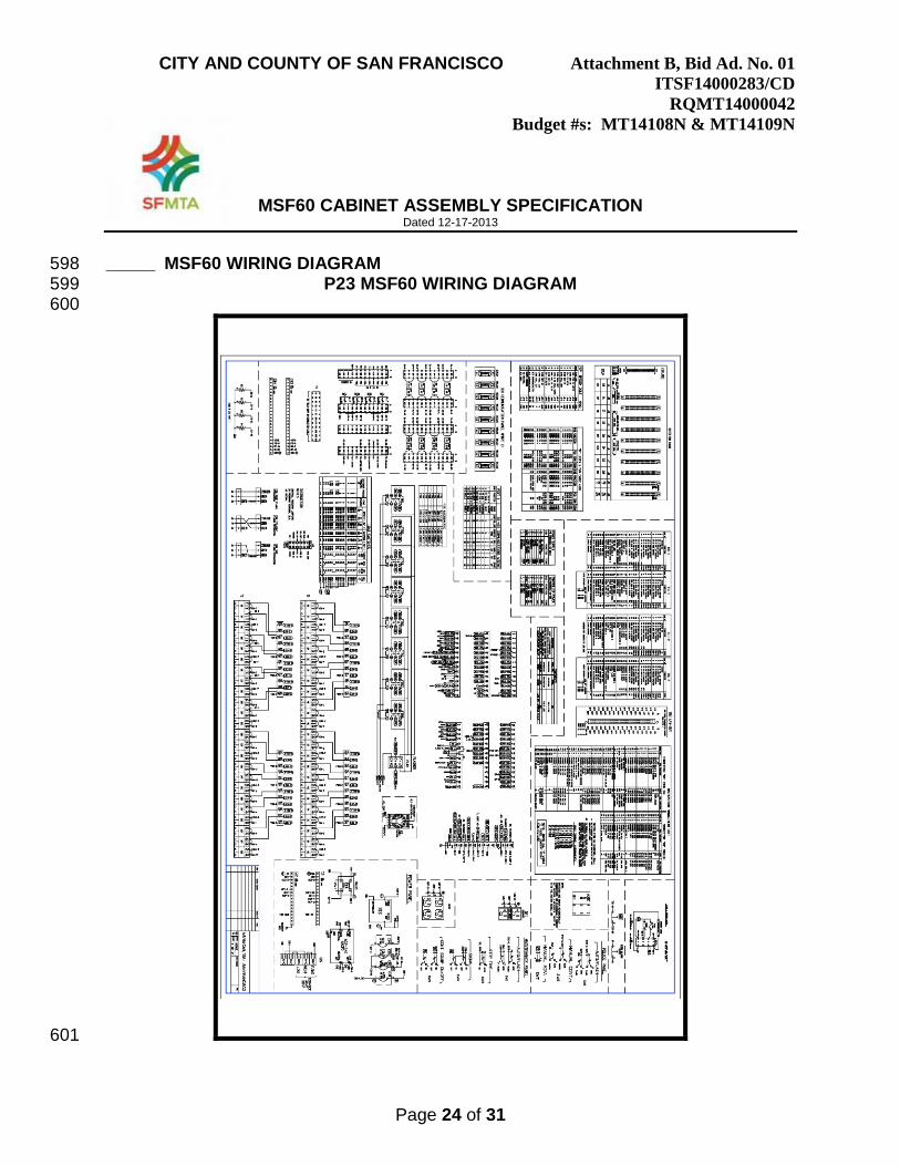
_____ MSF60 WIRING DIAGRAM 598 P23 MSF60 WIRING DIAGRAM 599
600
601

CITY AND COUNTY OF SAN FRANCISCO Attachment B, Bid Ad. No. 01 ITSF14000283/CD
RQMT14000042
Budget #s: MT14108N & MT14109N
MSF60 CABINET ASSEMBLY SPECIFICATION Dated 12-17-2013
Page 25 of 31
_____ MSF60 CABINET LAYOUT 602 P24 MSF60 CABINET LAYOUT 603
604
605 606

CITY AND COUNTY OF SAN FRANCISCO Attachment B, Bid Ad. No. 01 ITSF14000283/CD
RQMT14000042
Budget #s: MT14108N & MT14109N
MSF60 CABINET ASSEMBLY SPECIFICATION Dated 12-17-2013
Page 26 of 31
_____ MSF60 CABINET DOOR PDF SHEET 1 607 P25 MSF60 CABINET DOOR PDF SHEET 1 608
609
610 611 612

CITY AND COUNTY OF SAN FRANCISCO Attachment B, Bid Ad. No. 01 ITSF14000283/CD
RQMT14000042
Budget #s: MT14108N & MT14109N
MSF60 CABINET ASSEMBLY SPECIFICATION Dated 12-17-2013
Page 27 of 31
_____ MSF60 CABINET DOOR PDF SHEET 2 613 P26 MSF60 CABINET DOOR PDF SHEET 2 614
615
616 617

CITY AND COUNTY OF SAN FRANCISCO Attachment B, Bid Ad. No. 01 ITSF14000283/CD
RQMT14000042
Budget #s: MT14108N & MT14109N
MSF60 CABINET ASSEMBLY SPECIFICATION Dated 12-17-2013
Page 28 of 31
BID EXCEPTION SHEETS 618
Return with Bid if any exceptions are taken 619 620
Please Note: All exceptions to the City’s bid requirements must be listed on the 621 sheets provided. Only those exceptions that are listed on the sheets provided 622 will be evaluated. Any material exceptions may result in the rejection of the bid 623 and the bidder will not receive further consideration. 624 625 *Section Title, Line Number, & Page Number:________________________________ 626 627 Description:____________________________________________________________628
______________________________________________________________________629
______________________________________________________________________ 630
631 Alternative:_____________________________________________________________632
______________________________________________________________________633
______________________________________________________________________ 634
635 *Section Title, Line Number, & Page Number:________________________________ 636 637 Description:____________________________________________________________638
______________________________________________________________________639
______________________________________________________________________ 640
641 Alternative:_____________________________________________________________642
______________________________________________________________________643
______________________________________________________________________ 644
645 *Section Title, Line Number, & Page Number:________________________________ 646 647 Description:____________________________________________________________648
______________________________________________________________________649
______________________________________________________________________ 650

CITY AND COUNTY OF SAN FRANCISCO Attachment B, Bid Ad. No. 01 ITSF14000283/CD
RQMT14000042
Budget #s: MT14108N & MT14109N
MSF60 CABINET ASSEMBLY SPECIFICATION Dated 12-17-2013
Page 29 of 31
651 Alternative:_____________________________________________________________652
______________________________________________________________________653
______________________________________________________________________ 654
655 *Section Title, Line Number, & Page Number:________________________________ 656 657 Description:____________________________________________________________658
______________________________________________________________________659
______________________________________________________________________ 660
661 Alternative:_____________________________________________________________662
______________________________________________________________________663
______________________________________________________________________ 664
*Section Title, Line Number, & Page Number:________________________________ 665 666 Description:____________________________________________________________667
______________________________________________________________________668
______________________________________________________________________ 669
670 Alternative:_____________________________________________________________671
______________________________________________________________________672
______________________________________________________________________ 673
674 *Section Title, Line Number, & Page Number:________________________________ 675 676 Description:____________________________________________________________677
______________________________________________________________________678
______________________________________________________________________ 679
680

CITY AND COUNTY OF SAN FRANCISCO Attachment B, Bid Ad. No. 01 ITSF14000283/CD
RQMT14000042
Budget #s: MT14108N & MT14109N
MSF60 CABINET ASSEMBLY SPECIFICATION Dated 12-17-2013
Page 30 of 31
Alternative:_____________________________________________________________681
______________________________________________________________________682
______________________________________________________________________ 683
684 *Section Title, Line Number, & Page Number:________________________________ 685 686 Description:____________________________________________________________687
______________________________________________________________________688
______________________________________________________________________ 689
690 Alternative:_____________________________________________________________691
______________________________________________________________________692
______________________________________________________________________ 693
694 *Section Title, Line Number, & Page Number:________________________________ 695 696 Description:____________________________________________________________697
______________________________________________________________________698
______________________________________________________________________ 699
700 Alternative:_____________________________________________________________701
______________________________________________________________________702
______________________________________________________________________ 703
704 *Section Title, Line Number, & Page Number:________________________________ 705 706 Description:____________________________________________________________707
______________________________________________________________________708
______________________________________________________________________ 709
710

CITY AND COUNTY OF SAN FRANCISCO Attachment B, Bid Ad. No. 01 ITSF14000283/CD
RQMT14000042
Budget #s: MT14108N & MT14109N
MSF60 CABINET ASSEMBLY SPECIFICATION Dated 12-17-2013
Page 31 of 31
Alternative:_____________________________________________________________711
______________________________________________________________________712
______________________________________________________________________ 713
714 *Section Title, Line Number, & Page Number:________________________________ 715 716 Description:____________________________________________________________717
______________________________________________________________________718
______________________________________________________________________ 719
720 Alternative:_____________________________________________________________721
______________________________________________________________________722
______________________________________________________________________ 723
*Section Title, Line Number, & Page Number:________________________________ 724 725 Description:____________________________________________________________726
______________________________________________________________________727
______________________________________________________________________ 728
729 Alternative:_____________________________________________________________730
______________________________________________________________________731
______________________________________________________________________ 732
*Section Title, Line Number, & Page Number:________________________________ 733 734 Description:____________________________________________________________735
______________________________________________________________________736
______________________________________________________________________ 737
738 Alternative:_____________________________________________________________739
______________________________________________________________________740
______________________________________________________________________ 741