Embed Size (px)
Citation preview
CHAPTER 5
SOLID FILL TYPE DOCKS, PIERS AND WHARVES
Docks, piers and wharves constructed of a natural or artificial fill
surrounded by a vertical wall are considered solid fi.ll structures. While
there are many variations, anchored bulkheads are the most common wall
type. Others include cantilever sheet pile walls, cantilever "L" walls,
gabion walls, crib walls, cellular sheet pile walls, concrete caisson
walls, and walls supported by relieving platforms. Each wall type is
suitable for different applications depending on the required depth of
water, character of the foundation material, loads imposed, and. the
allowable movement once it is put in service. Basin depth depends on boat
size and berth layout plan, topics that were discussed in Chapter 2. Soil
properties and the loads soils impose on a retaining wall are addressed
by Saczynski and Kulhawy �982!. Wall structures are also described by
Zhrlich and Kulhawy �9S2! with regard to their use for erosion control
and wave protection.
This chapter presents a brief'discussion of each wall type, the
factors involved in selecting the proper wall type for a particular site
or application, and the design considerations pertaining to the use of solid
fill structures for docks, piers and wharves.
5. l WALL TYPES
Anchored Bulkheads and Cantilever Sheet, Pile Walls
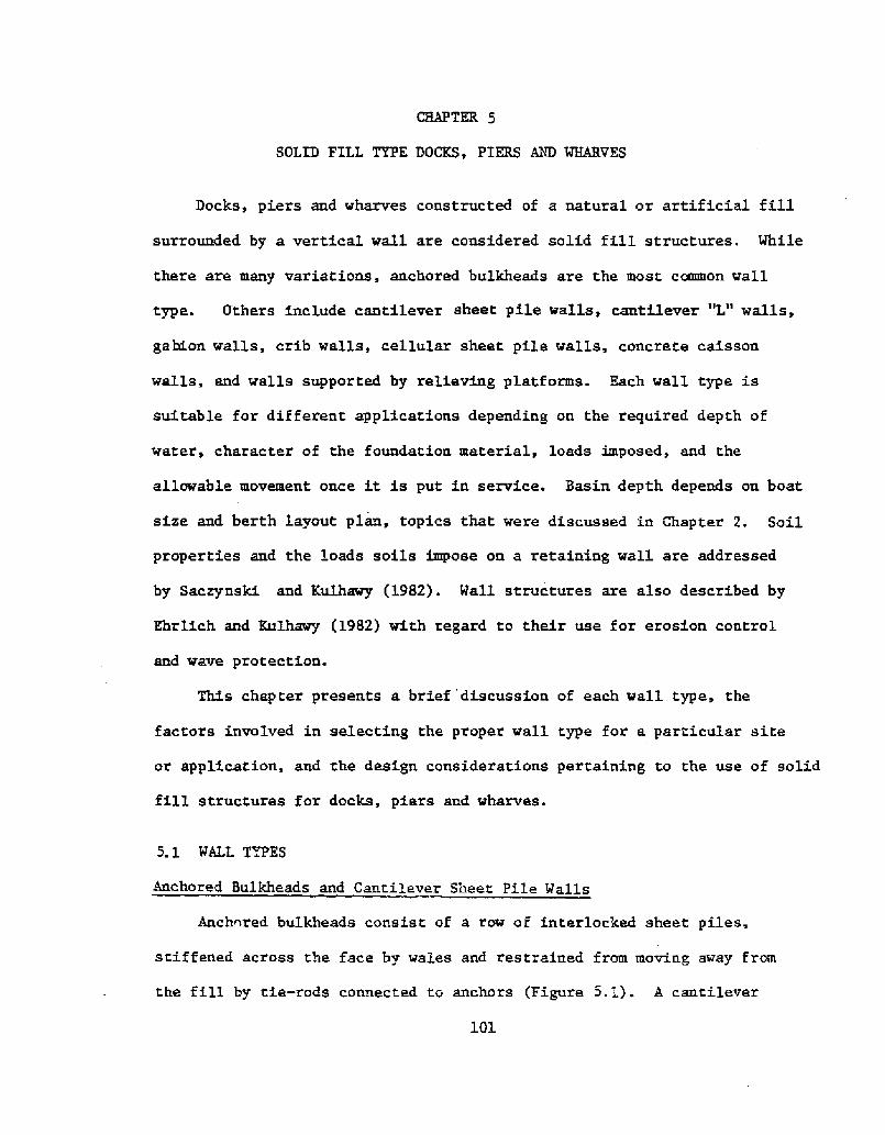
Anchored bulkheads consist of a row of interlocked sheet piles,
stiffened across the face by wales and restrained from moving away from
the fill by tie-rods connected to anchors Figure 5.1!. A canti.lever
101
3.02
Figure $.1 Anchored Bulkhead Wall Saczyaski and Kulhavy,1982, p. 8!
103
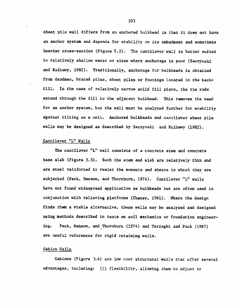
sheet pile walL differs from an anchored bulkhead in that it does not have
an anchor system and depends f' or stability on its embedment and sometimes
heavier cross-section Figure 5.2!. The cantilever wall is better suited
to relatively shallow water or sites where anchorage is poor Saczynski
and Kulhawy, 1982!. Traditionally, anchorage for bulkheads is obtained
from deadmen, braced piles, sheet piles or footings located in the back-
fill. In the case of relatively narrow solid fill piers, the tie rods
extend through the fill to the adjacent bulkhead. This removes the need
for an anchor system, but the wall must be analyzed further for stability
against tilting as a unit. Anchored bulkheads and cantilever sheet pile
walLs may be designed as described by Saczynski and Kulhawy �982!.
Cantilever "L" Walls
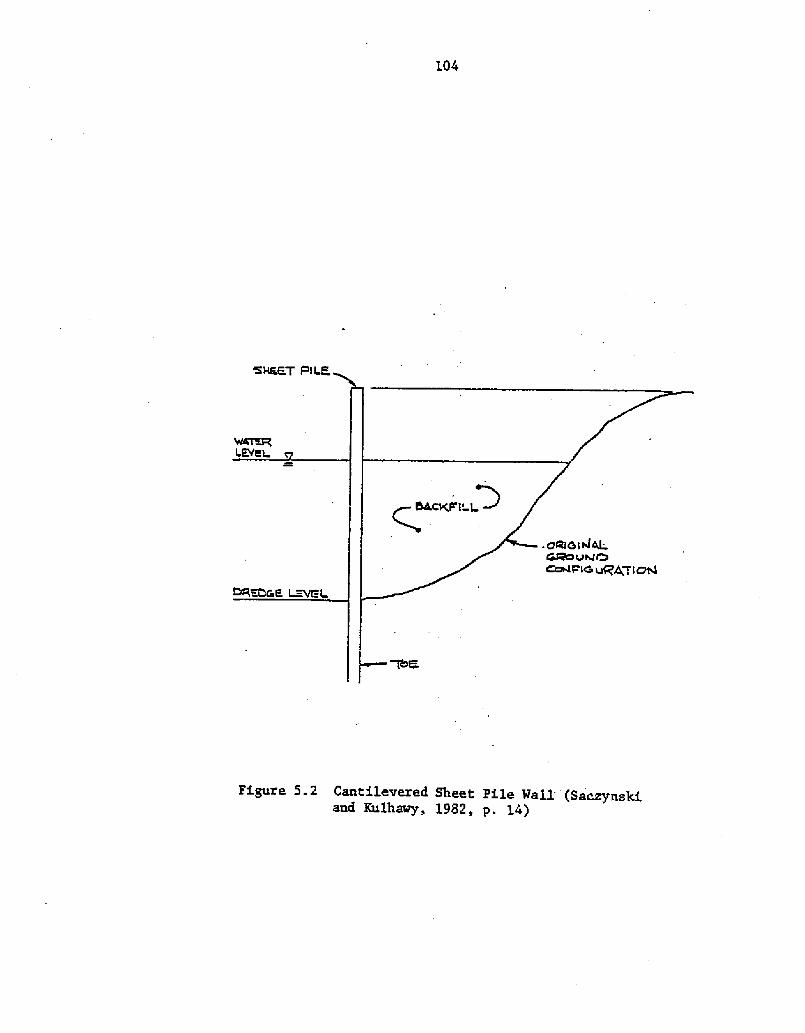
The cantilever "L" wall consists of a concrete stem and concrete
base slab Figure 5.3!. Both the stem and slab are relatively thin and
are steel reinforced to resist the moments and shears to which they are
subjected Peck, Hanson, and Thornburn, 1974!. Cantilever "L" walls
have not found widespread application as bulkheads but are often used in
conjunction with relieving platforms Chancy, 1961!. Where the design
finds them a viable alternative, these walls may be analyzed and designed
using methods described in texts on soil mechanics or foundation engineer-
ing. Peck, Hanson, and Thornburn �974! and Terzaghi and Peck �967!
are useful references for rigid retaining walls.
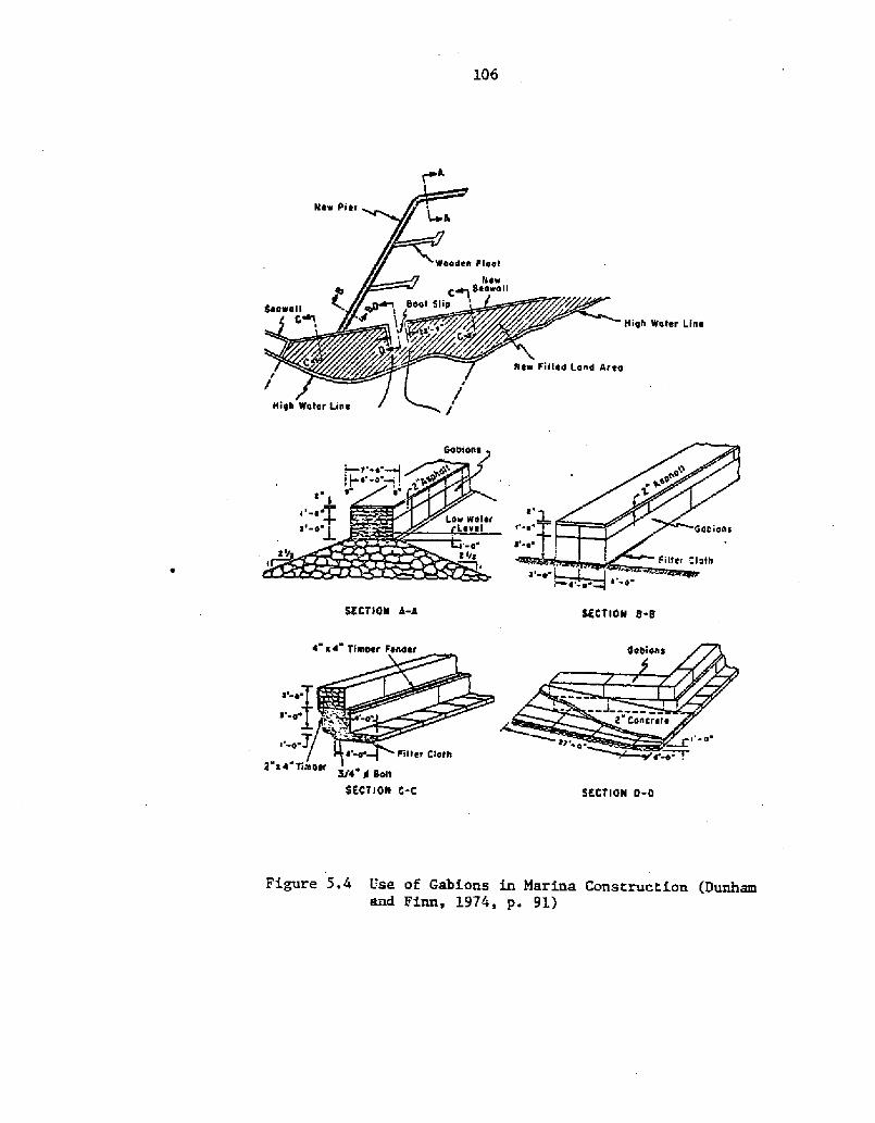
Gabion Walls
Gabions {Figure 5.4! are low cost structural walls that offer several
advantages, including: �! flexibility, allowing them to adjust to
104
Figure 5.2 Cantilevered Sheet Pile WalL Saczynskiand Kulhawy, 1982, y. 14!
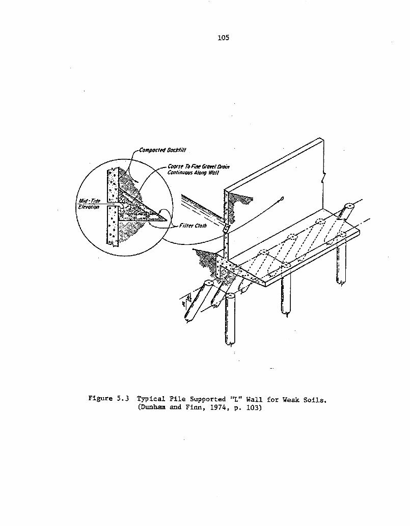
Figure 5.3 Typical Pile Supported "L" Wall for Weak Soils. Dunham and Finn, 1974, p. 103!
ttiqh water Line
SECTION 8 8S ECTION A-A
! ~ Ttnttter Fenaer
!' 4
SECTION O-O
Figure 5.4 Use of Gabions in Marina Construction Dunhamand Finn, 1,974, p. 9l!
5/4" ti saltSECTION C-C
iIe tti en!+
107
foundation irregularities and settlement, �! versatility, or the capa-
bility to be placed and filled under water with minimal problems, and
�! permeability, preventing the development of a hydrostatic head ir.
the backfill Hubbell and Kulhawy, 1979a!. Gabion assembly is labor
intensive and requires the rock fill to be hand placed before the lids are
"sewn" shut with wire. Protection in the form of a fender system or
facing material is a must for gabion walls since the wire mesh is sus-
ceptible to damage by impact which could allow the rock fill to spill out.
When used to support a solid fill structure, it is common practice to cap
the wall with a concrete slab Bekaert Gabions, 1977! which may dramatically
reduce flexibility. Gabions as a coastal material are discussed by
Bubbell and Kulhawy �979a! while Ehrlich and Kulhawy {1982! address the
use of gabions in coastal protection structures.
Crib Walls
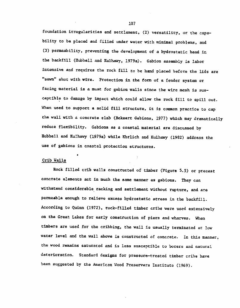
Rock filled crib walls constructed of timber Pigure 5.5! or precast
concrete elements act in much the same manner as gabions. They can
withstand considerable racking and. settlement without rupture, and are
permeable enough to relieve excess hydrostatic stress in the backfill.
According to Quinn �972!, rock-filled timber cribs were used extensively
on the Great Lakes for early construction of piers and wharves. When
timbers are used for t' he cribbing, the wall is usually terminated at low
water level and the wall above is constructed of concrete. In this manner,
the wood remains saturated and is less susceptible to borers and natural
deterioration. Standard designs for pressure-treated timber cribs have
been suggested by the American Wood Preservers Institute �969!.
108
Figure 5.5-' Typical Timber-Crib Wharf Quean, l972, p. 279!
109
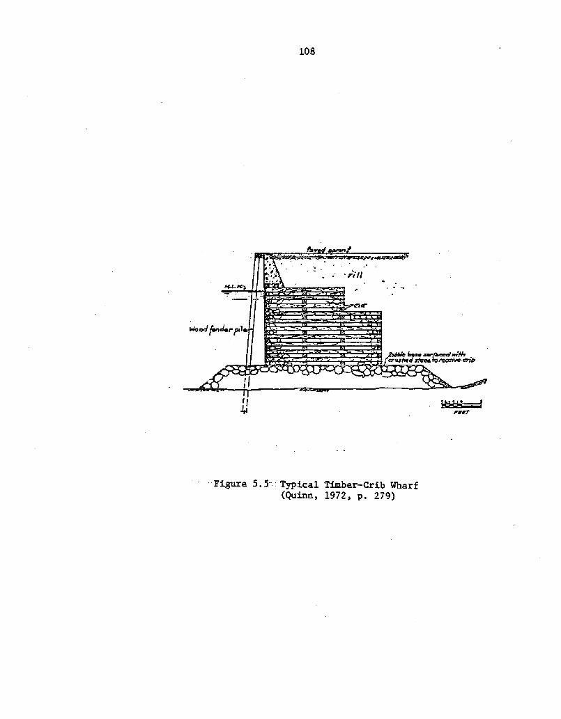
Cellular Sheet Pile Walls
One variation of the conventional steel sheet pile wall is the
celluLar wall type illustrated in Figure 5.6. The cellular sheet pile
wall possesses a high degree of stability in conditions where anchored
bulkheads are impractical. Lt should be considered for dock, pier
and wharf constnxction where the water depth is greater than the feasible
anchored bulkhead height, or where sufficient penetration may not
be obtained because of shallow bedrock Cummings, 1957!. To avoid sta-
bility problems or excessive settlement when used on soft materials,
predredging and placement of a foundation mat may be necessary. A
stability analysis for cellular sheet pile walls should include sliding
along the base, overturning as a unit, and rupture of the web and inter-
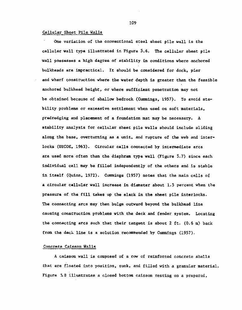
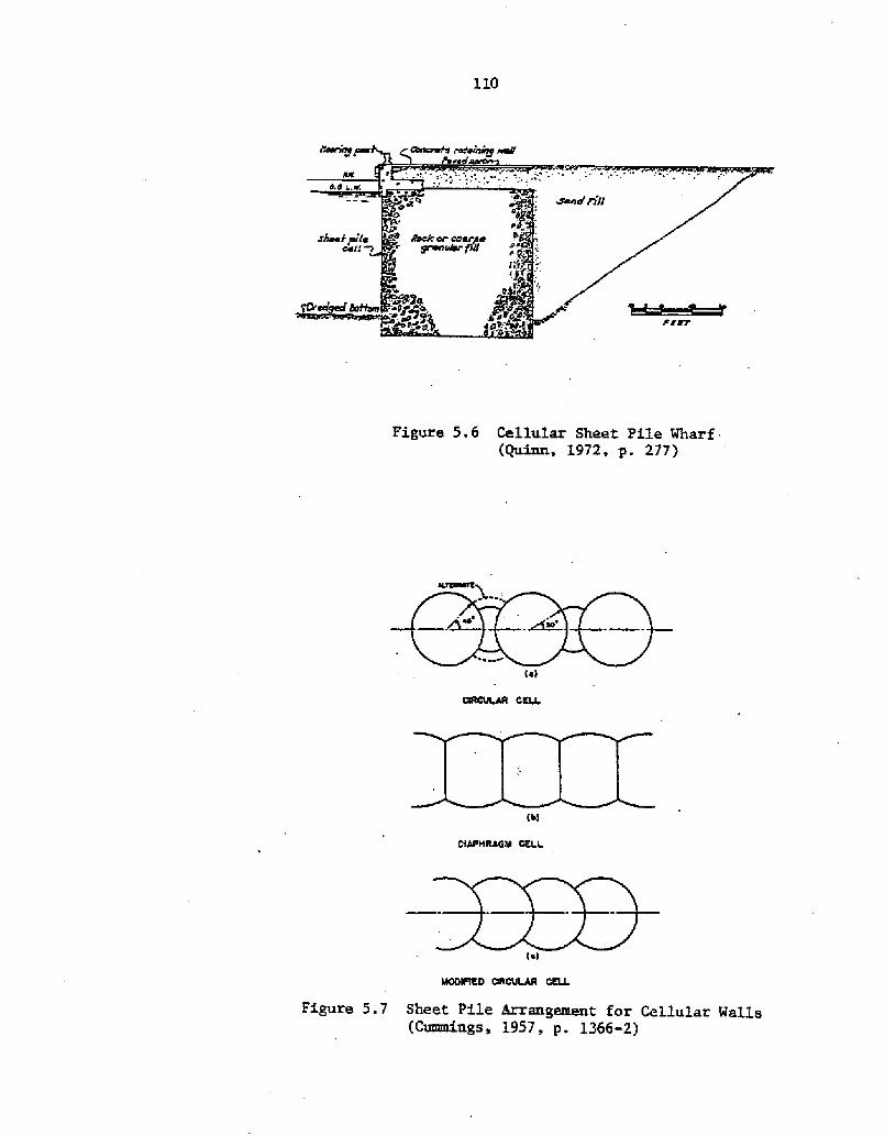
locks USCOK, 1963!. Circular cells connected by intermediate arcs
are used more often than the diaphram type wall Figure 5.7! since each
individual cell may be filled independently of the others and is stable
in itself Quinn, 1972!. Cummings �9S7! notes that the main cells of
a circular cellular wall increase in diameter about 1.5 percent when the
pressure of the fill takes up the slack in the sheet pile interlocks.
The connecting arcs may then bulge outward beyond the bulkhead line
causing construction problems with the deck and fender system. Locating
the connecting arcs such that their tangent is about 2 ft. �.6 m! back
from the deck line is a solution recommended by Cummings �9S7!.
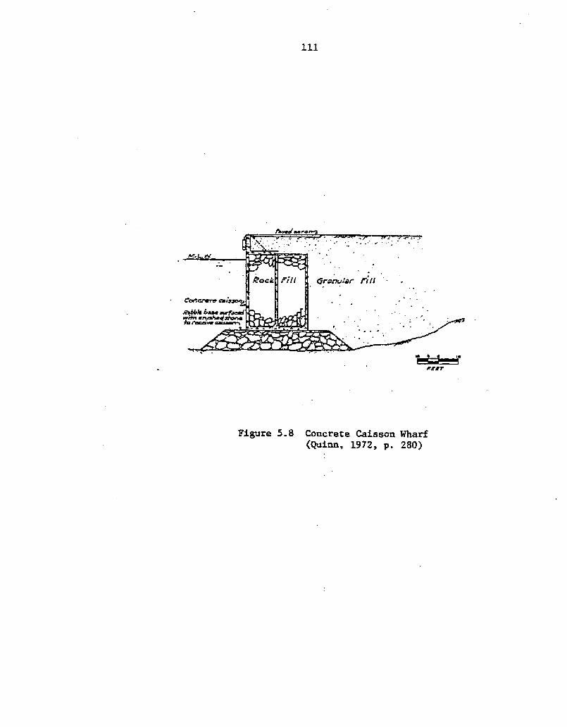
Concrete Caisson Walls
A caisson wall is composed of a row of reinforced concrete shells
that are floated into position, sunk, and filled with a granular material.
Figure 5.8 illustrates a closed bottom caisson resting on a prepared,
1.10
Figure 5.6 Cellular Sheet Pile Wharf Quinn, 1972, p. 277!
CRI~R CELL
Figure 5.7 Sheet Pile Arrangement for Cellular Walls Cuamdags, 1957, p. 1366-2!
111
Figure 5.8 Concrete Caisson Wharf Quinn, 1972, p. 280!
112
level foundation mat. Open well caissons with cutting edges that obtain
support by sinking into a soft bottom are also used Quinn, 1972!.
Caissons are usually designed so that their tops lie gust above the
Lowwater level. A cast-in-place concrete cap forms the upper part of
the dock face, allowing true alignment and grade as well as providing
for the attachment of the fender system, cleats, railings, and other
hardware. One of the advantages of concrete caissons is that much of
the construction work is performed on land for ease of access. In
addition, construction is much less dependent on weather and wave
conditions.
Relievin Platforms
A relieving platform type bulkhead combines many of the features
of walls previously discussed into one system. As Figure 5. 9 illustrates,
it consists of a concrete wall resting on a pile supported timber plat-
form. A. line of sheet piling retains the soil behind the bulkhead
while rip-rap under the platform provides stability. The rei.iev'ng
platform is suitable for greater water depths and softer under1ying mate-
rial than are sheet pile walls Chancy, 1961!. To minimize deterioration
and prolong its life, the timber members of the relieving platform should
be Locatei at or near the Low-water level so that they are continuously
wet. The rip-rap acts to reduce the stresses in the sheet pile wall
while at the same time protecting against Loss-of-ground from scour.
In addition, its sloped and porous surface absorbs wave energy and creates
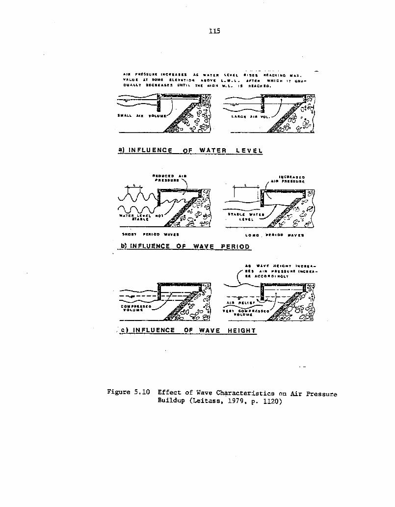
a calmer berthing environment. Depending on the geometry of the face
of the pLatform, problems can arise because of air pressure that causes
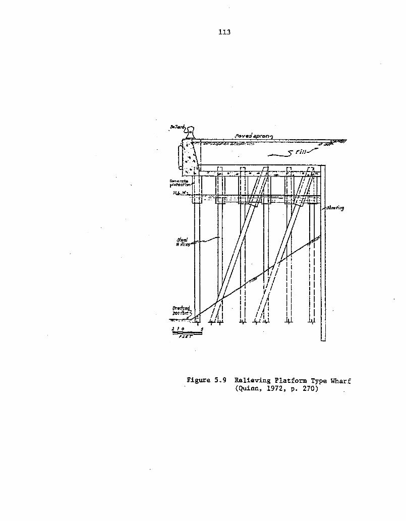
Figure 5.9 Relieving Platform Type Wharf Quinn, L972, p. 270!
114
structural damage and rip-rap instability Leitass, 1979!. Figure 5.3.0
illustrates the effect of wave characteristics on this air pressure
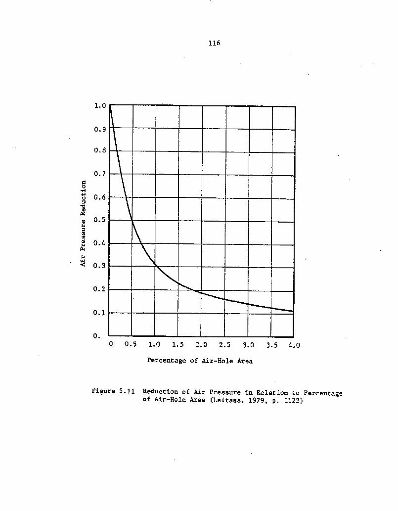
buildup, while Figure 5.11 shows the reduction of air pressure in relation
to relief hole area. Remedial measures include reducing the wave energy
with protective structures, resisting the air pressure by stronger plat-
form design, and arranging for air relief. While relieving platforms
are the most desirable wall type with respect to permanence and stability,
they are also the most costly to construct Chancy, 1961!.
5.2 SELECTION OF WALL TYPE
Each of the wall types discussed above has been constructed and has
performed effectively in harbors around the world. None of the wall types
are universally applicable to any given location, however. In addition
to sound design, construction and maintenance practices, a successful in-
stallation requires that the wall be well,-suited to the site conditions and
its intended application. The designer should consider the following
factors when selecting a wall type to be used at a particular location
after Chancy, 1961!:
in most marinas ranges from 8 to 12 ft �.5 to 3.5 m!
See Chapter 2!. For this wall height, anchored bulkheads
will be the most economical wall type, given sufficient
embedment and anchorage for stability.
2. Soft Substrata. When the substrata is composed of layers
of soft sediments, piles driven to "refusal" will show
less settlement than gravity structures such as crib
walls or concrete caissons.
A I 5 P RESS 4 5 5 I N C A E A S 5 5 A 5 WATER L 5 4 5 I. 5 t 5 5 5 RE AC H I It 5 Il A XvAI.VE AT SOWE ELEV*TION *SOvE L.W.L. APTER WNICN IT CRA-OVALLT SECRE*SE5 llNTI L TNE ttIOIt W L ~ IS REACIIEO
a! tNFLUENCE OF WATER LEVEL
REOVCED AIR I i!CAR* 5 5 5
5IIOR'l PER tOD WAVES I.O NO PER IOD w*v 55
b! /NFLUKN E OF WAVE PERIOD
AS WAVE RE IONT IN CREA
. c! !NFLUENCE OF WAVE HEIGHT
Figure 9.10 Effect of Wave Characteristics on Air PressureBuildup Leitass, 1979, p. 1120!
116
1.0
0.9
0.8
0.7
a u 0.6CC g 0.5
F 4
0.3
0.2
0.1
0. 0 05 10 15 20 25 30 35 4.0Percentage of Air-Hole Area
Figure 5.11 Reduction of Air Pressure in Relation to Percentageof Air-Hole Area Leitass, 1979, p. 1122!
3. Hard Substrata. When a dense layer of soil or rock lies at
a shallow depth below the dredging line, piles may not
penetrate far enough for adequate horizontal stability,
and concrete caissons or filled cribs may be more suitable.
Settlement. The use of gravity walls rock filled cribs
and concrete caissons! causes high contact stresses on
the foundation. When placed on relatively soft underlying
materials, these walls are subject to settlement and
horizontal slippage that may result in damage to walks,
buildings, and other structures resting on them.
dredge soft foundation materials and replace them with a
bedding layer of sand and gravel. This technique will
reduce settlements in gravity walls, and assure adequate
anchorage for sheet pile stability. Densification of
bottom materia1.s may also be achieved by loading with a
layer of rip-rap.
6. Berthin Access. The use of a relieving platform with a
line of sheet piles driven landward of the platform, or
sheet piling alone, driven at the face of the bulkhead
will permit dredging to full project. depth up to the
face of the wall. On the other hand, sloping rip-rap and
some crib walls will encroach considerably into the water
area and prevent boats from berthing along the wall.
7. Materials. The durability and disintegration of materials
when subjected to alternate wetting and drying should be
Ll8
considered when selecting a wall type. For material
px'operties see Chapter 4. Materials are also dis-
cussed. by Hubbell and Kulhawy �9>9a!.
5 3 GEOTECHNICAL DESIGN CONSIDERATIONS
Perimeter walls in small craft harbors are seldom used as breasting
docks permitting boats to tie up parallel to the wall face Dunham, 1969!.
Except for small scale prospects or private installations, breasting is
an inefficient use of dock space. Bow cIamps and stern hooks have been
used to moor small craft perpendicular to a perimeter wall, but they
are inconvenient to use and pose boarding problems.
Generally, solid fill structures are used to stabilize the boundary
walls of a harbor and provide anchorage and access to either a fixed
or floating berthing system. In some locations, fire and safety regula-
tions require that the fuel dock be of solid fill construction See
Chapter 8 on Utilities and Services!. Where solid fill docks, piers
and wharves are to be used, some areas of design deserve special attention.
The following discussi.on addresses foundation design, dredging, and back-
fill considerations for solid fill walls.
Foundation Desi Considerations
Foundation design is concerned with the interacti.on between a struc-
ture and Zne material it rests upon. In the case of waterfront struc-
tures such as docks, piers, and wharves, the underlying material usually
consists of layers of sand and clay. The in-place or undisturbed density
of these marine sediments is often quite low since they are deposited
undex' water in a very Loose condition. Although the engineering behavior
ll9
of clay in general is very complex, it should be sufficient for this
discussion to note that marine clays are often weak and highly com-
pressible. Sands, on the other hand, are much less compressible and
can be easily densified through vibration. In practice, soils range
continuously from fine-grained clay! to coar'se-grained sand! sizes.
Since the engineering properties of a soil are highly dependent on
grain size and in-situ condition, a geotechnical investigation is usually
performed to characterize the soil type, extent, and expected behavior.
The scope of such an investigation depends primarily on the scale of
the project and the discretion of the designer.
The character of the underlying soil is an important factor influenc-
ing the stability and settlement of a foundation. Zn addition, scour
potential is determined by the soil type to be transported as well as
the energy available to move it. Ideally, foundation design is intended
to protect structures from failure because of a lack of bearing capacity,
excessive settlement, rapid scour, or combinations of these. Unfor-
tunately, foundation design is often minimized in coastal structure
design, resulting in problems that are difficult and costly to repair.
The following discussion briefly addresses each of the possible failure
modes with respect to waterfront design. Xt is not within the scope
of this report to go into the details of geotechnical analysis; the
reader should r'efer to texts on soil mechanics and foundation engineering
for this information.
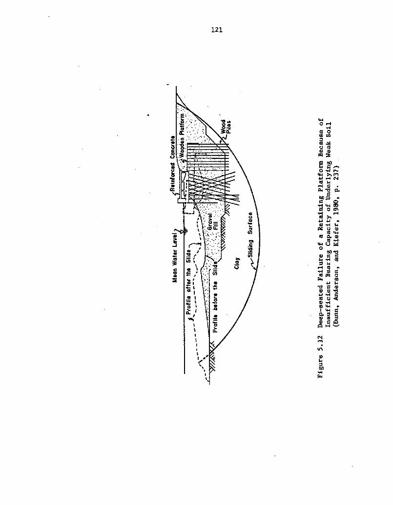
Bearin Ca acit . Bearing capacity refers to the ability of the
foundation to carry a load without failure within the soil. Failure
120
usuaLLy occurs because of shearing of the underlying strata and backfill
along a cuxved surface Figure 5.1 2!. Stability of a sheet pile wall de-
pends on the depth of embedment; greater embedment depth forces the failure
surface to go deeper and thereby mobilizes more resistance. Saczynski
and Kulhawy �982! present the procedures for analysis and design of
anchored bulkheads and cantilever sheet pile wal3.s. The stability of
gravity walls such as concrete caissons, cx'ibs and gabions is dependent on
the size of the base and the wall weight, and may be enhanced by the
placement of bedding layers.
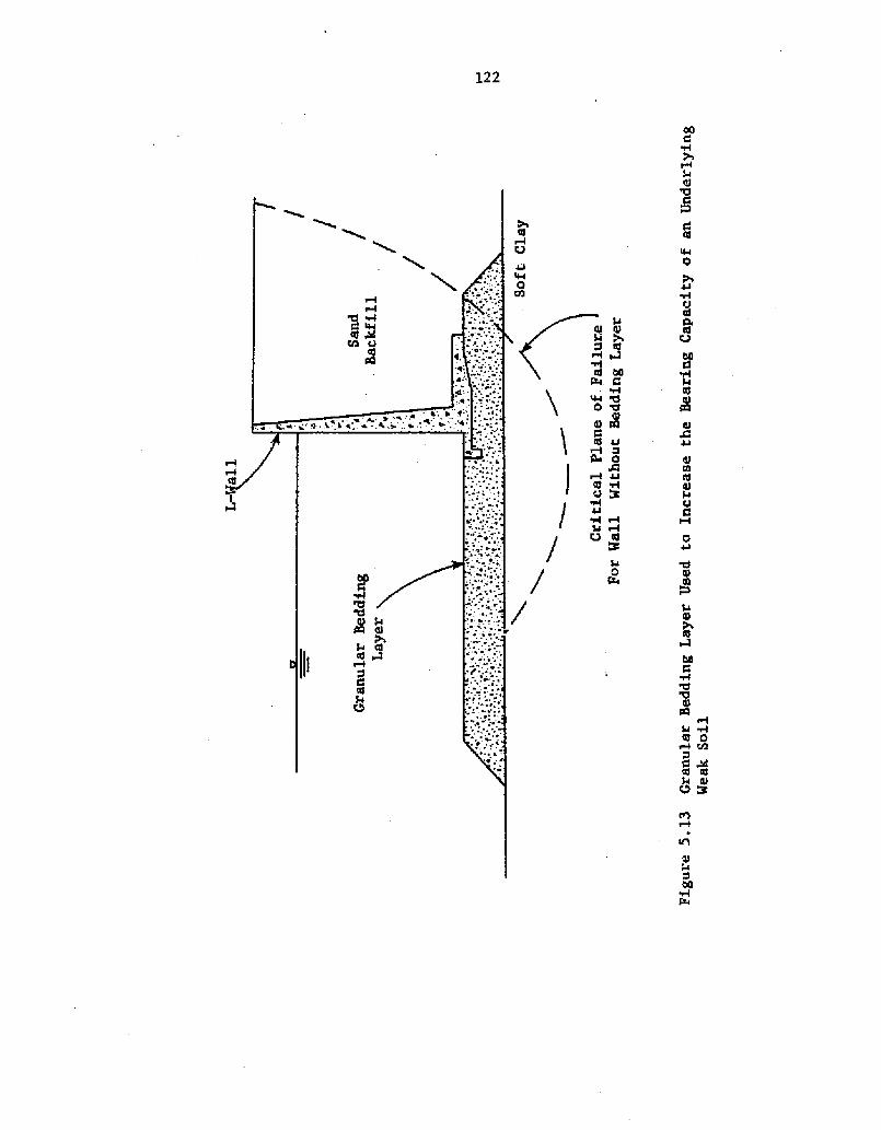
According to Quinn �972!, the bedding layer should extend beyond the
toe and the critical plane of failure so that its weight and strength in-
crease the factor of safety with respect to a shear failure at the toe
Figure 5.13!. A properly designed bedding layer will reduce settlement
by spx'eading out the wall load to decrease its contact pressure below,
provide a leveling course that facilitates constxuction, and protect the
foundation material against scour. Foundation blanket design is
addressed by Ehrlich and Kulhawy �982!.
Stability against a bearing capacity failure can on3.y be determined
through a detailed geotechnical analysis. The approach commonly used is to
analyze a number of possible failure planes and determine which is likely to
be critical. The conservative assumptions of a fully saturated backfill and
extreme 3.ow water at the face of the wall are made to simulate the worst ex-
pected service condition. A. more critical state can be created during con-
struction if poorly administered hydraulic fills are used in conjunction
with dredging in front of the wall. According to the Committee for
Waterfront Structures �966!, a temporary lateral pressure may exist with an
0 W
Cl 0 I Q3
gAvtl! lQ
8f0&m4J HCVC
Q ~0
Cgg a~WR
0 Ch
44I 4J
4 WRl 0 Q.
wog0
bO M8
C4
tQaf Pl 0
�4J
'O 0 I8 tll &4J
Ol H8 W a
WC4 J8 tOQl C Ch
0 V al0 ClC!
0A4J
Ol
8 S g 00'a S$Cl
C 0
cd gt4 A
QV W
123
intensity somewhere neax' the hydrostatic pressure of a material with
the density of the slux'ry and the earth pressure at rest of the
consolidated hydraulically filled soil. The actual pressure will
depend on the degx'ee of consolidation the fill has reached.
Settlement. Settlement relates to the downward movement of a struc-
ture during and after construction. The two ma!or causes of settlement
of waterfront structures are the consolidation of weak, compressible
soils in the foundation and the removal of supporting soil from scour.
Scoux' related settlement is discussed in a subsequent section.
Settlement is not always detrimental to solid fill docks, piers
and wharves. Uniform settlement can be tolerated as long as the wall
remains functional and buried utilities are not damaged. Gn the other
hand, differential settlement from compressible strata of irregular
thickness can easily result in structural damage to the wall- that. will
lead to complete failure. Some wall types, notably gabion and timber crib
walls, are more resistant to differential settlement and racking than
are rigid walls. While a deformed wall may be structux'ally sound, its
appearance can deter usexs such that it consti.tutes a functional failure.
Although good foundation design cannot eliminate settlement, its
magnitude may be reduced and. its effects mitigated so that it is no
longer harmful to the structure.
Consolidation settlement is a timeMependent phenomenon that occurs
when a surcharge load is placed above a layer of soft substrata. One
method of controlling this settlement is to place a temporary surcharge
to "preconsolidate" the soil. After consolidation is complete� the sur-
charge is removed and is replaced by a wall structure and backfill. A
124
disadvantage of preconsolidation is that substantial time measured
perhaps in years! is necessary for completion, especially if the
foundation materials are fina-grained with low permeabili,ty. Aa alter-
native suggested by Quinn �972! is excavation and replacement of the
compressible layer with a more competent material. Foundation mats are
commonly used beneath gravity walls to provide a stable base for con-
struction and minimize settlement. Design of these mats is presented
by Ehrlich and Kulhawy �982!.
Scour. Bulkheads must be both vertical and smooth-faced to serve
properly as a dock, pier or wharf. Unfortunately, such a barrier is a
very efficient reflection of wave energy and is accepted as the primary
cause of bed scour. Since scour potential is greatest at the toe of
a wall where its smooth face meets the foundation material, progressive
excavation will take place ~til undermining, 'stability and settlement
problems occur. The situation may be aggravated if excess hydrostatic
pressures are allowed to build up in the backfill as in the case of
hydraulic fill placement. Water will then flow along a path leading
under the toe of the wall and cause a reduction in the soil strength
and resistance to erosion.
When scour-induced erosion is expected to be a problem, protection
is commonly provided in the form of a foundation blanket. While the
blanket serves as a mat to distribute wall loads over a larger area and
reduce settlement and bearing capacity problems, it. must also be designed
as a filter to avoid the loss of fines through its voids. The mechanism
125
of scour and protective measures including foundation blanket design
are addressed by Ehrlich and Kulhawy �982!. Additional references that
should be consulted include HaLe �9 80! on site ~ecific scour problems,
scour control methods and construction techniques, and Keown and Dardeau
�980! on filter fabrics and filter design criteria.
Dr~ed ~in
While the general topic of dredging is presented later in this report
S ee Chapter 9!. some of the aspects of dredging that relate to solid
fill structures should be mentioned here. The dredging process occurs
in two phases. The first or initial phase is performed when the harbor
basin is originally excavated for navigation. Dredging must precede
placement of a foundation mat for gravity type walls. In the case of
sheet pile walls, however, Saczynski and Kulhawy �982! recommend that
dredging operations be conducted after wall construction is complete
and the backfill has been placed and consolidated. This delay allows
arching to occur in the backfill that wiLL reduce the stress level in
the wall and result in less outward deflection.
The second or maintenance phase of dredging must be carefuLLy
administered to avoid. over-dredging and hitting the wall. Over-dredging
adjacent to the wall should not be allowed since excavation of material
below the original design depth will result in a Loss of toe support
and possible stability problems. Depending on the dredge method used,
it is relatively easy to damage bulkheads structurally by hitting them.
The dredge operator must exercise caution and proceed more slowly than
usual.
Another important aspect of dredging is the disposal of the excavated.
126
material. Assuming the soil is acceptable backfill material, using it
for fill behind the wall is obviously more efficient than wasting it
sway from the site. The use of dredge spoil for backfill is discussed
subsequently while other disposal methods are addressed in Chapter 9.
Backf ill
The second step in solid fill dock, pier or wharf construction
following the completion of the wall is the placement of the backfill.
The type of fill material and method of placement used are important
parameters determining wall stability and long-term performance. These
topics are addressed in the following discussions.
The strength and engineering behavior of cohesive soils or clays is
highly variable and depends on mineralogy, structure, stress history and
water content. Low permeability and poor drainage is characteristic of clay
fills causing them to consolidate for long periods of time, and to develop
hydrostatic imbalances under the action of heavy rain or rapid tides. A
successful clay backfill requires that the same type of soil be used
throughout and that special attention be given to the water content and
compactive effort during placement so that a uniform solid mass is achieved.
The Committee for waterfront Structures �966! suggests, however,-
that compaction of clay backf ills causes considerable additional earth
pressure that may damage an otherwise sound wall. Zn light of these
problems, cohesive backfills should be used only when cohesionless
materials are not available within a reasonable radius of transportation.
Saczynski and Kulhawy �982! suggest that a coarse-grained, free-
draining backfill should be used whenever possible. Because the engineer-
ing behavior of these cohesiouless materials sands and gravels! 's
127
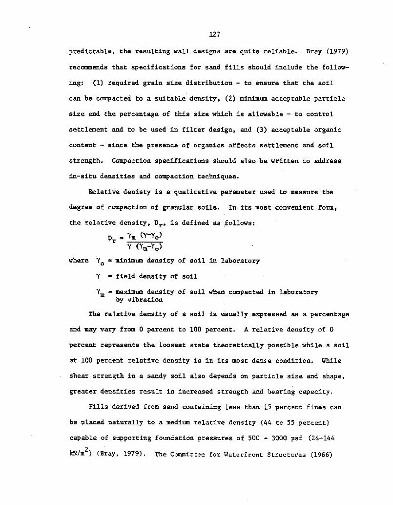
predictable, the resulting wall designs are quite reliable. Bray �979!
recommends that specifications for sand fills should include the follow-
ing: �! required grain size distribution - to ensure that the soil
can be compacted to a suitable density, �! minimum acceptable particle
size and the percentage of this size which is allowable � to control
settlement and to be used in filter design, and �! acceptable organic
content � since the presence of organics affects settlement and soil
strength. Compaction specifications should also be written to address
in-situ densities and compaction techniques.
Relative denisty is a qualitative parameter used to measure the
degree of compaction of granular soils. Xn its most convenient form,
the relative density, Dr, is defined as follows:
m Y-Yo!Y Ym-Yo!
where Y minimum density of soil in laboratory
Y ~ field density of soil
Y maximum density of soil when compacted in laboratoryby vibration
The relative density of a soiL is usually expressed as a percentage
and may vary from 0 percent to 100 percent. A relative density of 0
percent represents the loosest state theoretically possible while a soil
at 100 percent relative density is in its most dense condition. While
shear strength in a sandy soil also depends on particle size and shape,
greater densities result in increased strength and bearing capacity.
FILLs derived from sand containing less than 15 percent fines can
be placed naturally to a medium relative density �4 to 55 percent!
capable of supporting foundation pressures of 500 - 3000 psf �4-144
2k<fm ! Bray, 1979! ~ The Committee for Waterfront Structures �966!
128
notes that a relative density of around 85 percent may be obtained by
placing the fill in well-compacted layers.
Placement of backfill material is accomplished by either mechanical
or hydraulic means. Mechanical methods include dumping by truck, or
dropping from a clamshell, dipper, or drag bucket. The fill is first
placed in piles aad then distributed into even layers with a bulldozer.
Hydraulic fills are created by pumping a soil/water mixture iato a
contaminant area through a pipeline. Hydraulic fills are very convenient
whea granular materials must be dredged nearby, but they create some
special problems. Ponding of the water in the reclamation area should
not be allowed since fines may be segregated into mud pockets. Unfor-
tunately, the initial fill behind a bulkhead must often be placed under-
water. Bray �979! suggests that this initial layer be formed to a
level 2 to 3.5 ft. �.5 to 1 m! above the maximum level of the water
in front of the wall. Subsequent layers 3.5 ft. � m! thick can be
added as compaction and consolidation is achieved. Saczynski and Kulhawy
�982! note that the fill should be placed in even lifts along the length
of the wall to avoid local overstressing.
Compaction of sandy fills is commonly achieved through the use of
vibroflotation or a vibratory roller. Vibratory compaction is effective
oaly in well-drained soils and becomes less efficient with increasing
silt or clay content. Vibroflotatioa can be conducted 'above or below
the water table and is accomplished by insertiag a vibrating probe into
the fill and feeding the annular space around the probe with additional
fill material as it is withdrawn Bray, 1979!. A grid spacing of less
than 15 ft. � m! is normally required to obtain full coverage or 80
129
percent relative density using a 100 horsepower probe. Vibratory rollers
are used above the water tabl.e where the density that may be achieved
depends on the soils moisture content. Bray �979! suggests that a
vibratory frequency of 1500 to 1700 Hz is most effective in compacting
sands.
En areas of active seismicity or intense industrial or construction
activity, sand backfills are subject to liquefaction. The vibration of an
earthquake, blasting, or heavy equipment acts in much the same manner as
vibratory compaction but on a much larger scale. The effect is known as
liquefaction and is manifested in a sudden, temporary loss of shear
strength. Liquefaction potential depends on soil grain size and density
and is greatest for silts and fine sands of uniform gradation. The risk
of liquefaction is minimized by specifying a well-graded granular backfill
to be compacted as dense as passible.
5.4 S~mm
Solid. fill structures are rarely used for berthing because of their
inefficient use of space and high cost compared to fixed or floating docks
or piers. They are more suitable for stabilization and protection of
the harbor perimeter and for the construction of marginal wharves.
Selection of the type of solid fill wall depends on site specific
conditions and the scope of the pro]ect. Anchored bulkheads are the most
common wall type for recreational marines because of their low cost and
ease of construction.
Solid fill walls must be designed against bearing capacity failures,
excessive settlement, undermining from scour, or combinations of these.
Design itself follows the procedures of soil mechanics and foundation
130
engineering and should be performed by a competent geotechnical engineer.
Attention must be given to dredging and backfill operations to control
the forces acting on a wall and to avoid damage during construction.