Embed Size (px)
Citation preview
' .
TYPEHK STORED--ENERGY METAL--CLAD SWITCHGEAR
Bulletin 8.2-lC
www . El
ectric
alPar
tMan
uals
. com
www . El
ectric
alPar
tMan
uals
. com
2
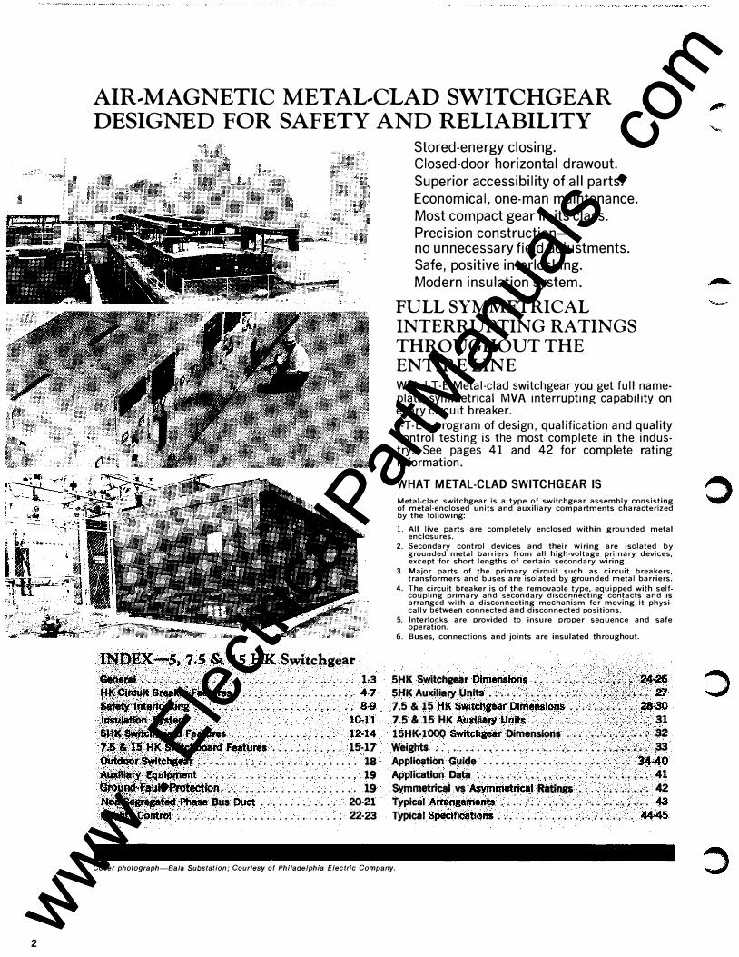
AIR .. MAGNETIC METAL .. CLAD SWITCHGEAR DESIGNED FOR SAFETY AND RELIABILITY
l�p�:--5,.1.5 &. IS .HK Switchgear •••.••• ·-:· .' ; • . • . • • ; . �.; • . . . . • . . . .•. . . . . 1·3 AKQ.�Bt4aketf"eatutes- . . . . • . . . . . • , • . . . . . . . +7
-�:::::::::::::::::::·!�T! 1� tt�.$ HK Switeb1)(;8td Feat!!"'S . . . . . • . . . . . . 15·17 �r$witcll&ear . . . . .. , . . . . . . . . . . . . . . . . . . . . . 18 ��IY �ipinent .. .. .. . .. • .. .. .. . . .. .. . .. . 19 tlt®�fa):llt. �rbtect-ion . . . . . . . . . . . . . . . . . . . . . . 19
'· Pita$& .Bus ou� . . . . . . . . . . . . . . 20-21 ·:·eohlrot . . . . . . . . . . . . . . . . . . . . .. . . . . . . 22·23
Stored-energy closing. Closed-door horizontal drawout.
Superior accessibility of all parts. Economical, one-man maintenance. Most compact gear in its class. Precision construction-no unnecessary field adjustments. Safe, positive interlocking. Modern insulation system.
FULL SYMMETRICAL
INTERRUPTING RATINGS
THROUGHOUT THE
ENTIRE LINE With ITE Metal-clad switchgear you get full nameplate symmetrical MVA interrupting capability on every circuit breaker.
1-T-E's program of design, qualification and quality control testing is the most complete in the industry. See pages 41 and 42 for complete rating information.
WHAT METAL-CLAD SWITCHGEAR IS
Metal-clad switchgear is a type of switchgear assembly consisting of metal-enclosed units and auxiliary compartments characterized by the following:
1. All live parts are completely enclosed within grounded metal enclosures.
2. Secondary control devices and their wiring are isolated by grounded metal barriers from all high-voltage primary devices, except for short lengths of certain secondary wiring.
3. Major parts of the primary circuit such as circuit breakers, transformers and buses are isolated by grounded metal barriers.
4. The circuit breaker is of the removable type, equipped with selfcoupling primary and secondary disconnecting contacts and is arranged with a disconnecting mechanism for moving it physically between connected and disconnected positions.
5. lnterlo�ks are provided to insure proper sequence and safe operatoon.
6. Buses, connections and joints are insulated throughout.
5HK SWI.tchgea· r Dimensw.n_s l ,' ·�----- ... ·.· 26. IVU -�- ,._- ., ._ • .,-. -,., ·�-··._ 4:/··�·�·sf"�:�,;.� � SHK Auxiliaf)' Units . . . • • - . . . • • , ; _ . . . , • ... }. :b�� . , 2:7 7.5 & 15 HK Switcfl8ear DiMepsionl; .... ; .. • ; . �. 28•30 7.5 & 15 HK Auxifiary Units .... : • • ; • . • • . 31 15HK·1000 Switchgeai DimefiSiC>OS . ; . . � . . • • • . -32 Weights • . . • . . • • . • . . . • • . . . • . .. • • . � • • · • • · •.• . 33 Application Guide ...................... : • . $4-40 Application Data . • . . . . . . . . . . . . . • . • • • • • . . • • • . . 41 Symmetrical vs Asymrneti'k:al Ratings • . • • •.• ' . � . 42 Typical A�ngemeJlt$ ........ , .. , . . . , • : : • • ; , . . 43 Typical Speeiftcatiom ................ , , • . . • . 44-45
Cover photograph-Sa/a Substation; Courtesy of Philadelphia Electric Company.
-
www . El
ectric
alPar
tMan
uals
. com
www . El
ectric
alPar
tMan
uals
. com
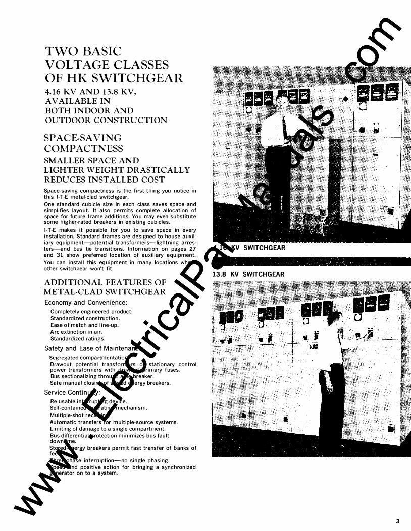
TWO BASIC VOLTAGE CLASSES OF HK SWITCHGEAR 4.16 KV AND 13.8 KV,
AVAILABLE IN
BOTH INDOOR AND
OUTDOOR CONSTRUCTION
SPACE .. SA VING COMPACTNESS SMALLER SPACE AND
LIGHTER WEIGHT DRASTICALLY
REDUCES INSTALLED COST
Space-saving com pactness is the first thing you notice i n this 1-T-E metal-clad switchgear_
One standard cu bicle size in each class saves space and simpl ifies layout. It also permits complete al location of space for future frame additions. You may even substitute some h igher-rated breakers in existing cubicles.
1-T-E makes it possible for you to save space in every i nstal lation. Standard frames a re designed to house a uxi l iary eq uipment-potential transformers-lightning arresters-and bus tie transitions. Information on pages 27 a nd 31 show preferred location of a uxil iary equi pment.
You can i nsta l l this eq u ipment in many locations where other switchgear won't fit.
ADDITIONAL FEATURES OF
METAL-CLAD SWITCHGEAR
Economy and Convenience:
Completely engineered product. Standard ized construction. Ease of match and l i ne-up.
Arc extinction i n a ir. Standard ized ratings.
Safety and Ease of Maintenance:
Segregated compartmentation. Drawout potential transformers or stationary control power transformers with d rawout primary fuses. Bus sectional iz ing through a tie breaker. Safe manual closing of stored energy breakers.
Service Continuity:
Re-usable i nterrupting device. Self-contai ned operating mechanism.
M ultiple-shot reclosing.
Automatic transfers for m ultiple-source systems. L imiting of damage to a single com pa rtment.
Bus d ifferential protection min imizes bus fau lt downtime.
Stored-energy breakers permit fast transfer of banks of feeders.
Three-phase interruption-no single phasing. Speed a nd positive action for bringing a synchronized generator on to a system.
4.16 KV SWITCHGEAR
13.8 KV SWITCHGEAR
.. ' • i -
3 www . El
ectric
alPar
tMan
uals
. com
www . El
ectric
alPar
tMan
uals
. com
4
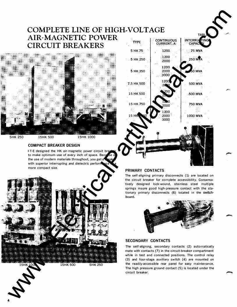
COMPLETE LINE OF HIGH .. VOLTAGE
5HK 250
AIR .. MAGNETIC POWER CIRCUIT BREAKERS
1 5HK 500 1 5HK 1000
COMPACT BREAKER DESIGN
1-T-E designed the HK air-magnetic power c ircuit breaker
to make optimum use of every inch of space_ Because of
the use of modern materials th roughout, you get a breaker
with superior i nterrupting and dielectric performance in a
more compact size_
1 5HK 1000 1 5HK 500 5HK 250
TYPE
5 HK75
5 HK 250
5 HK350
7_5 HK 500
1 5 HK 500
1 5 HK 750
1 5 HK 1 000
CONTINUOUS CURRENT, A
1200
1 200 2000
1200 2000 3000
1200 2000
1 200 2000
1200 2000
1 200 2000 3000
PRIMARY CONTACTS
TABLE 1
INTERRUPTING CAPACITY
75MVA
250 MVA
350 MVA
500 MVA
500 MVA
750 MVA
1 000 MVA
The self-a ligning primary disconnects (1) a re located on
the circuit breaker for complete accessibi l ity_ Conserva
tively designed lock-wound, stai n less steel mu lti ple
springs insure good high-pressu re contact with the sta
tionary primary d isconnects (6) located i n the switchboard_
SECONDARY CONTACTS
The self-aligning, secondary contacts (2) a utomatically
mate with contacts (7) in the circu it-breaker compartment
wh i le in test and connected positions_ The control relay
(3) and fou r-stage auxi l iary switch (4) are mou nted on
the readily-accessible rear panel for easy mai ntenance_
The high pressu re ground contact (5) is located u nder the
circuit breaker.
www . El
ectric
alPar
tMan
uals
. com
www . El
ectric
alPar
tMan
uals
. com
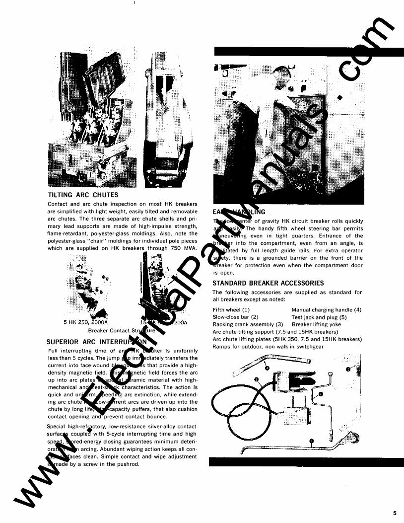
TILTING ARC CHUTES
Contact and arc chute inspection on most HK breakers
are simplified with light weight, easily tilted and removable
arc chutes. The three separate arc chute shells and pri
mary lead supports are made of high-impulse strength,
flame-retardant, polyester-glass moldings. Also, note the
polyester-glass "chair" moldings for individual pole pieces
which are supplied on HK breakers through 750 MVA.
Breaker Contact Structure
SUPERIOR ARC INTERRUPTION
Full interrupting time of any HK breaker is uniformly
less than 5 cycles. The jump gap immediately transfers the
current into face-wound blowout coils that provide a high
density magnetic field. This magnetic field forces the arc
up into arc plates of special ceramic material with high
mechanical and heat-shock characteristics. The action is
quick and uniform, speeding arc extinction, while extend
ing arc chute life. Low-current arcs are driven up into the
chute by long life, high-capacity puffers, that also cushion
contact opening and prevent contact bounce.
Special high-refractory, low-resistance silver-alloy contact
surfaces coupled with 5-cycle interrupting time and high
speed, stored-energy closing guarantees minimum deteri
oration from arcing. Abundant wiping action keeps all con
tact surfaces clean. Simple contact and wipe adjustment
is made by a screw in the pushrod.
EASY HANDLING
The low center of gravity HK circuit breaker rolls quickly
and easily. The handy fifth wheel steering bar permits
maneuvering even in tight quarters. Entrance of the
breaker into the compartment, even from an angle, is
facilitated by full length guide rails. For extra operator
safety, there is a grounded barrier on the front of the
breaker for protection even when the compartment door
is open.
STANDARD BREAKER ACCESSORIES
The following accessories are supplied as standard for
all breakers except as noted:
Fifth wheel (1) Manual charging handle (4)
Slow-close bar (2) Test jack and plug (5)
Racking crank assembly (3) Breaker lifting yoke
Arc chute tilting support (7.5 and 15HK breakers)
Arc chute lifting plates (5HK 350, 7.5 and 1 5HK breakers)
Ramps for outdoor, non walk-in switchgear
5 www . El
ectric
alPar
tMan
uals
. com
www . El
ectric
alPar
tMan
uals
. com
6
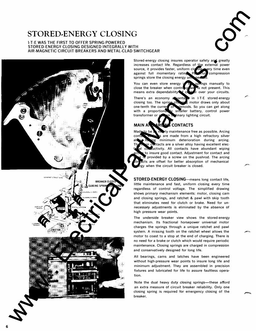
STORED .. ENERGY CLOSING 1-T-E WAS THE FIRST TO OFFER SPRING-POWERED STORED-ENERGY CLOSING DESIGNED INTEGRALLY WITH AIR-MAGNETIC CIRCUIT BREAKERS AND METAL-CLAD SWITCHGEAR
BREAKER CLOSEO
Stored-energy closing insures operator safety and greatly increases contact life. Regardless of the external power source, it provides faster, uniform closing every time even against full momentary rating. Powerful compression springs store the closing energy until needed.
You can even store energy in the springs manually to close the breaker when control power is not present. This means extra dependability of control over your circuits.
There's an economy advantage in 1-T-E stored-energy closing too. The spring charging motor draws only about one-tenth the current of solenoids. So you can get along with a proportionately smaller battery, control power transformer or use an ordinary lighting circuit.
MAIN AND ARCING CONTACTS
Made to be as nearly maintenance free as possible. Arcing contact surfaces are made from a high refractory silver alloy having mm1mum deterioration during arcing. The main contacts are a silver alloy having excellent electrical conductivity. All contacts have abundant wiping action to insure good contact. Adjustment for contact and wipe is provided by a screw on the pushrod. The arcing contacts are offset for better absorption of mechanical energy when the circuit breaker is closed.
STORED-ENERGY CLOSING-means long contact life,
little maintenance and fast, uniform closing every time
regardless of control voltage. The simplified drawing
shows primary mechanism elements: motor, closing cam
and closing springs, and ratchet & pawl with skip tooth
that eliminates need for clutch or brake. Need for un
necessary adjustments is eliminated by the absence of
high pressure wear points.
The underside breaker view shows the stored-energy
mechanism. Its fractional horsepower universal motor
charges the springs through a unique ratchet and pawl
system. A missing tooth on the ratchet wheel allows the _,., motor to coast to a stop at the end of charging. There is
no need for a brake or clutch which would require periodic
maintenance. Closing springs are charged in compression
and conservatively designed for long life.
All bearings, cams and latches have been engineered
without high-pressure wear points to insure long life and
minimum adjustment. They are assembled in precision
fixtures and lubricated for life to assure faultless opera
tion.
Note the dual heavy duty closing springs-these afford
an extra measure of circuit breaker reliability. Only one
closing spring is required for emergency closing of the
breaker.
www . El
ectric
alPar
tMan
uals
. com
www . El
ectric
alPar
tMan
uals
. com
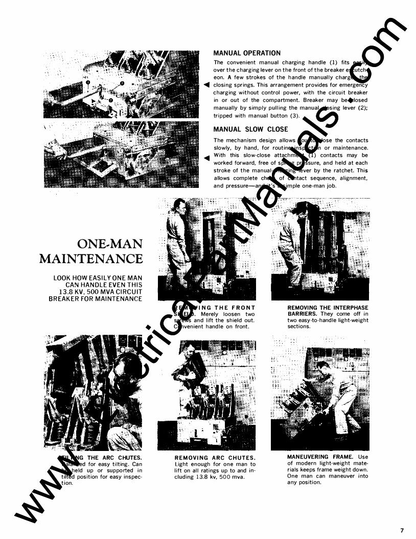
ONE .. MAN
MAINTENANCE
LOOK HOW EASILY ONE MAN CAN HANDLE EVEN THIS
13.8 KV, 500 MVA CIRCUIT BREAKER FOR MAINTENANCE
TILTING THE ARC CHUTES. Bala nced for easy tilting. Ca n be held up or supported in tilted position for easy inspec· tion.
MANUAL OPERATION
The convenient man ual charging handle (1) fits easily
over the charging lever on the front of the breaker escutch·
eon. A few strokes of the handle man ually charges the
� closi ng springs. This arrangement provides for emergency
charging without control power, with the circuit breaker
in or out of the compartment. B reaker may be closed
manually by simply pulling the manual closing lever {2);
tripped with manua l button (3).
MANUAL SLOW CLOSE
The mechanism design a l lows you to close the contacts
slowly, by hand, for routine inspection or maintenance .
.... With this slow-close attachment (1) contacts may be
worked forwa rd, free of spring pressu re, and held at each
stroke of the man ual-charging lever by the ratchet. This
allows complete check of contact sequence, a lignment,
and pressure-and it's a simple one-man job.
R E M O V I N G T H E F R O NT SHIELD. Merely loosen two screws and lift the shield out. Convenient handle on front.
REM O V I N G ARC CH UTES. Light enough for one man to lift on all ratings up to and in · e luding 13.8 kv, 500 mva .
REMOVING THE INTERPHASE BARRIERS. They come off i n two easy-to-handle light-weight sections.
MANEUVERING FRAME. Use of modern light-weight mate· rials keeps frame weight down. One man can maneuver i nto a ny position.
7
www . El
ectric
alPar
tMan
uals
. com
www . El
ectric
alPar
tMan
uals
. com
8
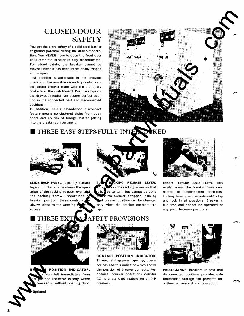
CLOSED .. DOOR SAFETY
You get the extra safety of a solid steel barrier
at ground potential during the drawout opera
tion . You NEVER have to open the front door
until after the breaker is fully discon nected.
For added safety, the breaker can not be
moved unless it has been intentionally tripped
and is open .
Test position is automatic in the drawout
operation . The movable secondary contacts on
the circuit breaker mate with the stationary
contacts in the switchboard. Positive stops on
the drawout mechanism assure perfect posi
tion in the connected, test and discon nected
positions.
In addition, 1-T·E's closed-door disconnect
feature mea ns no cluttered aisles from open
doors and no risk of foreign matter getting
into the breaker compartment .
• THREE EASY STEPS .. fULLY INTERLOCKED
S LIDE BACK PANEL. A plai nly marked
legend on the outside shows the oper·
ation of the racking release lever and
the racki n g s c rew. Rega rdl ess of
breaker position, these controls are
always close to the opening for easy
access .
TURN RACKING RELEASE LEVER.
This u nlocks the racking screw so that
it is free to turn, but can not be done
unless the breaker is tripped, insuring
that breaker position can be cha nged
only when the breaker contacts are
open.
• THREE EXTRA SAFETY PROVISIONS
BREAKER P O S I TION IND I CATOR.
Operator can tell immed iately from
th is position i ndicator exactly where
the breaKer is without open i ng door.
*Optional
CONTACT P OSITION IND I CAT OR.
Through sliding panel opening, opera
tor can see this i ndicator which shows
the position of breaker contacts. Me·
chanica! breaker operations counter
(1) is a sta ndard feature on all HK breakers.
INSERT CRANK AND T URN. This
easily moves the breaker from con·
nected to disconnected positions.
Locking lever provides automatic stop and lock i n all positions. Breaker is
trip free and can not be operated at
any point between positions.
PADLOCK ING*-breakers in test and
disconnected positions provides safe
u nattended storage and prevents un
authorized removal and operation .
www . El
ectric
alPar
tMan
uals
. com
www . El
ectric
alPar
tMan
uals
. com
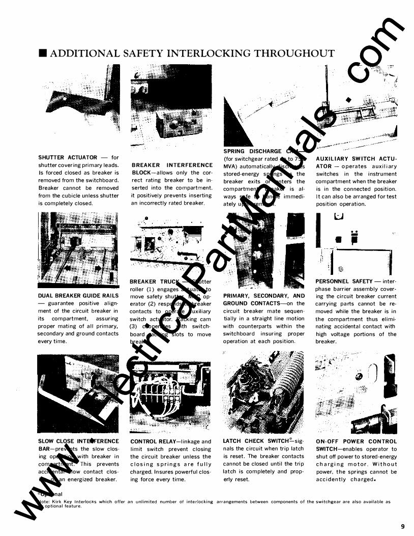
• ADDITIONAL SAFETY INTERLOCKING THROUGHOUT
SHUTTER ACTUATOR - for
shutter covering primary leads.
Is forced closed as breaker is
removed from the switchboard.
Breaker cannot be removed
from the cubicle unless shutter
is completely closed.
DUAL BREAKER GUIDE RAILS
- guarantee positive align·
ment of the circuit breaker in
its compartment, assuring
proper mating of all primary,
secondary and ground contacts
every time.
SLOW CLOSE INTERFERENCE
BAR-prevents the slow clos
ing operation with breaker in
compartment. This prevents
accidental slow contact clos
ing of an energized breaker.
':'Optional
B REAKE R I NTE R FE RE NCE
BLOCK-allows only the cor
rect rating breaker to be in
serted into the compartment.
it positively prevents inserting
an incorrectly rated breaker.
BREAKER T RUCK - Shutter
roller (1) engages actuator to
move safety shutter. MOC op
erator (2) responds to breaker
contacts to operate auxiliary
switch actuator. Racking cam
(3) cooperates with switch
board racking slots to move
breaker.
CONTROL RELAY-lin kage and
limit switch prevent closing
the circuit breaker unless the
c l o s i n g s p ri n g s a r e f u l l y
charged. I n sures powerful clos
ing force every time.
SPRING DISCHARGE CAM
(for switchgear rated up to 750
MVA) automatically discharges
stored-energy springs as the
breaker exits or enters the
compartment. Breaker is al
ways safe to handle immedi
ately upon removal .
PRIMARY, SECONDARY, AND
GROUND CONTACTS-on the
circuit breaker mate sequen
tially in a straight line motion
with counterparts within the
switchboard insuring proper
operation at each position.
LATCH CHECK SWITCH�sig
nals the circuit when trip latch
is reset. The breaker contacts
can not be closed until the trip
latch is completely and prop·
erly reset.
A UXILIARY SWITCH ACT U·
ATO R - operates auxiliary
switches in the instrument
compartment when the breaker
is in the con nected position.
It can also be arranged for test
position operation.
I • ••
;
PERSONNEL SAFETY - inter
phase barrier assembly cover·
ing the circuit breaker current
carrying parts cannot be re·
moved while the breaker is in
the compartment thus elimi
nating accidental contact with
high voltage portions of the
breaker.
O N-OFF POWE R CONTROL
SWITCH-enables operator to
shut off power to stored-energy
c h a rgi n g m o t o r . Wi t h o u t
powe� t h e springs can not be
acci d e n tly c ha rged.
Note: Kirk Key I nterlocks which offer an unlimited number of interlocking arrangements between components of the switchgear are also available as an optional feature.
9 www . El
ectric
alPar
tMan
uals
. com
www . El
ectric
alPar
tMan
uals
. com
10
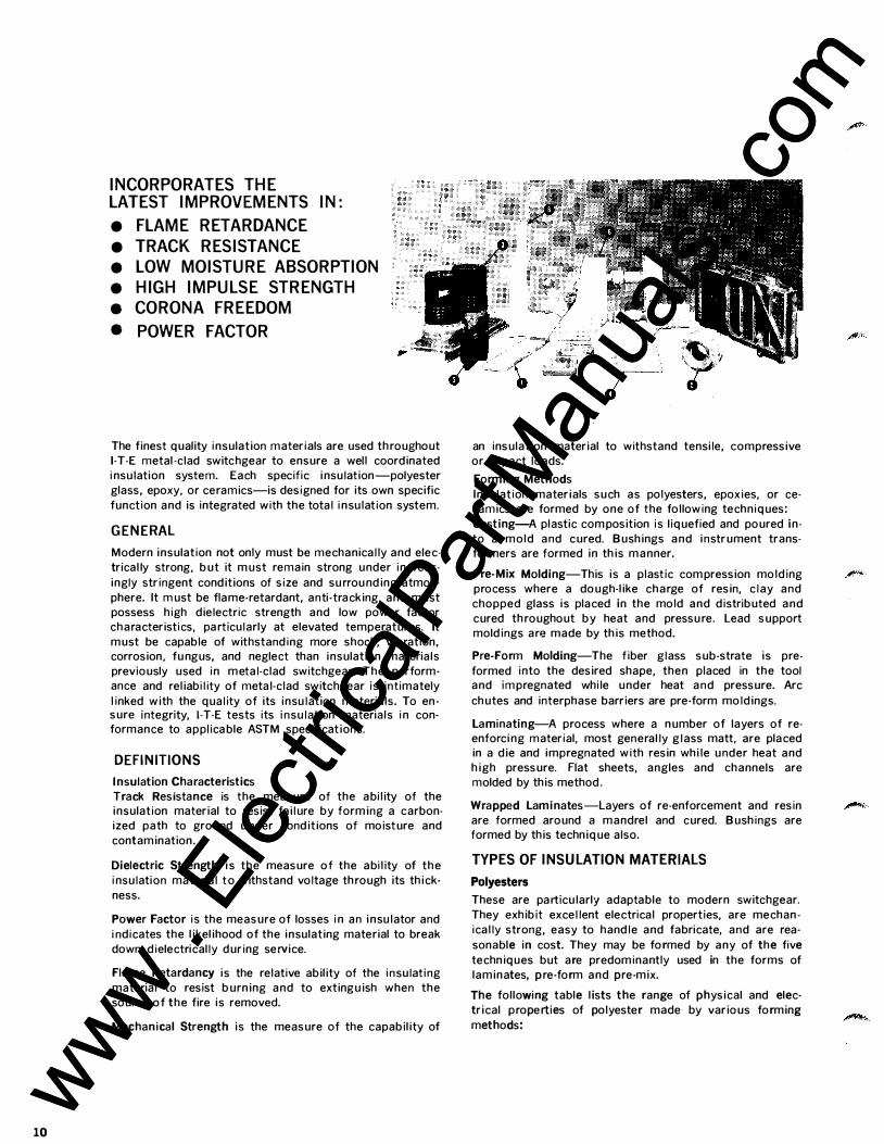
INCORPORATES THE LATEST IMPROVEMENTS IN: e FLAME RETARDANCE e TRACK RESISTANCE e LOW MOISTURE ABSORPTION e HIGH IMPULSE STRENGTH • CORONA FREEDOM • POWER FACTOR
The finest quality insulation materials are used th roughout 1-T-E metal -clad switchgear to ensure a well coordinated insulation system. Each specific insulation-polyester
glass, epoxy, or ceramics-is designed for its own specific
function and is integrated with the total insulation system.
GENERAL
Modern insulation not only must be mechanically and elec
trical ly strong, but it must remain strong under increas
ingly stringent conditions of size and surrounding atmos
phere. It must be flame-retardant, anti-tracking, and must possess high dielectric strength and low power factor characteristics, particularly at elevated temperatures. It
must be capable of withstanding more shock, vibration, corrosion, fungus, and neglect than insulation materials
previously used in metal-clad switchgear. The performance and reliability of metal-clad switchgear is intimately
linked with the quality of its insulation materials. To ensure integrity, 1-T-E tests its insulation materials in conformance to applicable ASTM specifications.
DEFINITIONS
Insulation Characteristics
Track Resistance is the measure of the ability of the insulation material to resist failure by forming a carbonized path to ground u nder conditions of moisture and
contamination .
Dielectric Strength is the measure of the ability of the
insulation material to withstand voltage th rough its thick
ness.
Power Factor is the measure of losses in an insulator and
indicates the likelihood of the insulating material to break
down dielectrically during service.
Flame Retardancy is the relative ability of the insulating
material to resist burning and to extinguish when the source of the fire is removed.
Mechanical Strength is the measure of the capability of
an insulation material to withstand tensile, compressive
or impact loads.
Forming Methods
Insulation materials such as polyesters, epoxies, or ceramics are formed by one of the following techniques:
Casting-A plastic com position is liquefied and poured in
to a mold and cured. Bushings and instrument transformers are formed in this manner.
Pre-Mix Molding-This is a plastic com pression molding process where a dough-like charge of resin, clay and
chopped glass is placed in the mold and distributed and
cured th roughout by heat and pressure. Lead support moldings are made by this method.
Pre-Form Molding-The fiber glass sub-strate is pre
formed into the desired shape, then placed in the tool and impregnated while under heat and pressure. Arc
chutes and interphase barriers are pre-form moldings.
Laminating-A process where a number of layers of reenforcing material, most generally glass matt, are placed in a die and impregnated with resin while under heat and high pressure. Flat sheets, angles and channels are
molded by this method.
Wrapped Laminates-Layers of re-enforcement and resin are formed around a mandrel and cured. Bushings are formed by this technique also.
TYPES OF INSULATION MATERIALS
Polyesters These are particularly adaptable to modern switchgear.
They exhibit excellent electrical properties, are mechan
ically strong, easy to handle and fabricate, and are rea
sonable in cost. They may be formed by any of the five
techniques but are predominantly used in the forms of
laminates, p re-form and pre-mix.
The following table lists the range of physical and elec
trical properties of polyester made by various forming
methods:
www . El
ectric
alPar
tMan
uals
. com
www . El
ectric
alPar
tMan
uals
. com
CHARACTERISTIC PRE-FORM PRE-MIX LAMINATE
Flexu ra I Strength, psi 18-20,000 14·15,000 18-20,000 Tensile Strength, psi 15,000 6·7,000 15,000 Compressive Strength, psi 20,000 23-27,000 30,000 lzod Impact, ft. lbs./in.
of notch 8-12 3-6 8-12 Flame Retardancy Yes Yes Yes Dielectric Strength
(Short Time) vpm V." tk., 25°C 350-375 350-375 350-375 Dielectric Constant 4-6 4-7 4-6 Power Factor o/o, 60 Hz,
25°C 0.5-3 0.5-3 0.5-3 Power Factbr o/o, 60 Hz,
105°C 3-7 2-7 3-7 Track Resistance hrs. 200+ 200+ 200+
Epoxies
The epoxy resins are some of the newest and most versa
tile of the modern plastics. Their chief adva ntages a re their excellent electrical and mechanical properties. They
are exceedingly tough, show excellent adhesion and excel
lent impregnating qualities. These resins give off no byproducts during cure and show very low cure shrinkageless than 2%-
Epoxies are most generally formed by casting tech niques.
They are excellent for voltage and current transformers,
bushings, a nd low volume items. They are pa rticularly
good in bonding a pplications. They are low enough i n vis
cosity that they can be used to im pregnate between fine wires used on transformers.
The following table compares the physical and electrica l properties of epoxy systems formed by various methods:
PRE-MIX CHARACTERISTIC CASTING LAMINATE (GLASS)
Flexural Strength, psi 17,000 40-50,000 24,000 Tensile Strength, psi 8,000 35-40,000 20,000 Compressive Strength, psi 22,000 60,000 32,000 lzod I mpact, ft. lbs./in. of
notch .3-.5 8-30 8-15 Dielectric Strength (Short Time)
vpm V." tk., 25°C 450 500 350 Dielectric Constant 4 4 4 Power Factor o/o, 60 Hz, 25oc 1.0 1.5 1.5 Power Factor o/o, 60 Hz, 105°C 4.0 6.0 6.0
Ceramics
Because ceramics are relatively inert, except at exceed
ingly high temperatures, they are used in critical a reas of
the switchgear. The following table shows typical physical and electrical properties of ceramic materials.
CHARACTERISTIC CORDIERITE
Flexural Strength, psi 8-10,000 Tensile Strength. psi 4,000 Impact ft., lbs./sq. in. 1 Specific Gravity, gms/cc 2.31 Moisture Absorption % 1-2 Thermal Expansion, in./in./°F
77-1290°F 2.8 X 1Q-6 Thermal Shock cycles 32-23000F 100+ Dielectric Strength, vpm, 25°C 100 Dielectric Constant 5
SWITCHBOARD INSULATION':' Bus
PORCELAIN
10.500 6.000
1.5 2.50
0
5.2 X 10⁻⁶ 1
300 6.1
All bus, including bends and odd configurations, is fully insulated with an epoxy compound (1). Bus joints, taps,
and splices are covered with a low power factor, air filled
vinyl boot (2). The boots a re placed over the bus joints and a re secured in place with nylon fasteners, thereby making joints accessible with a minimum of effort. 7.5 and 1 5 H K bus is supported by wet process procelain (3). The mai n bus is carried th rough the wall of the frame with
porcelain bus supports imbedded in polyester glass. 5 H K
bus is supported with track resistant polyester-glass
angles and the main bus is carried th rough the wall of
the frame with polyester-glass pre-mix parts (4).
Current Transformers A rigid epoxy case is cast and the current transformer is potted in the base and enca psulated with a flexible epoxy
resin (5). Shutters and Primary Disconnects The safety shutter covering the stationary primary discon nects of 5 and 15 HK switchgear th rough 750 MVA is made of a polyester laminate which exhibits high track
resistance, high flexural strength, good dielectric strength and flame reta rdancy. For 15 HK 1000 switchgear, the shutter is aluminum . Directly behind the safety shutter a re the stationary primary disconnects (3). 7.5 and 15 H K primary disconnects (up to 7 5 0 MVA) a re porcelain hous
ings mounted on track-resista nt polyester-glass pre-forms
bonded with an epoxy compound. 15 HK 1 000 primary disconnect housings a re mounted on aluminum. The primary conductors a re mounted to the porcelain housings with an epoxy compound. The disconnect housings for 5 HK a re made of polyester-glass pre-mix molding compound.
CIRCUIT BREAKER INSULATION':' Lead Assembly
Lead support moldings (6) are basically a polyester-glass pre-mix molding compound (through 750 MVA) which sup
port the circuit breaker continuous current components and isolate them from ground. 15 H K 1 000 MVA circuit breakers utilize epoxy bushings mounted to metal f rames.
Push rods a re the insulating link between the breaker
mechanism and the moving contact bridge. A wrapped laminate of epoxy glass cloth is used for the push rod. A gas deflector of highly track-resistant polyester is bonded
to the rod to serve as a seal which prevents the possibility
of ionized gases blowing into the operating mechanism.
Arc Chute Assembly The arc chute and coil assembly (7) a re made of high impact, track-resistant polyester pre-mix for 5 H K and pre
form for 7.5 and 15 H K. Arc chute halves a re bonded
together with epoxy and bolted, thereby preventing ionized gases f rom blowing through the joints. The a rc chute is formed so that coils can be potted directly onto the shel l and recesses are formed to receive the ceramic liners (8).
The liners are cemented to the shell adjacent to the contacts. The arc plates a re made of an exceptional ly high
heat shock material known as cordierite (see Ceramics
above).
Interphase Barrier Assembly
The interphase barrier assembly has the primary function of increasing air strike distance between the phases. The
front of the interphase barrier is pre-form molding polyester-glass. Polyester-glass laminates a re bonded to either
side of the pre-form with epoxy.
*Refer to photograph on page 10 for i l l ustration of various insulators used in HK metal-clad switchgear.
11 www . El
ectric
alPar
tMan
uals
. com
www . El
ectric
alPar
tMan
uals
. com
12
5HK
I .. T .. E PROVES HOW CONVENIENT,
SAFE,AND PROTECTIVE SWITCHGEAR CAN BE
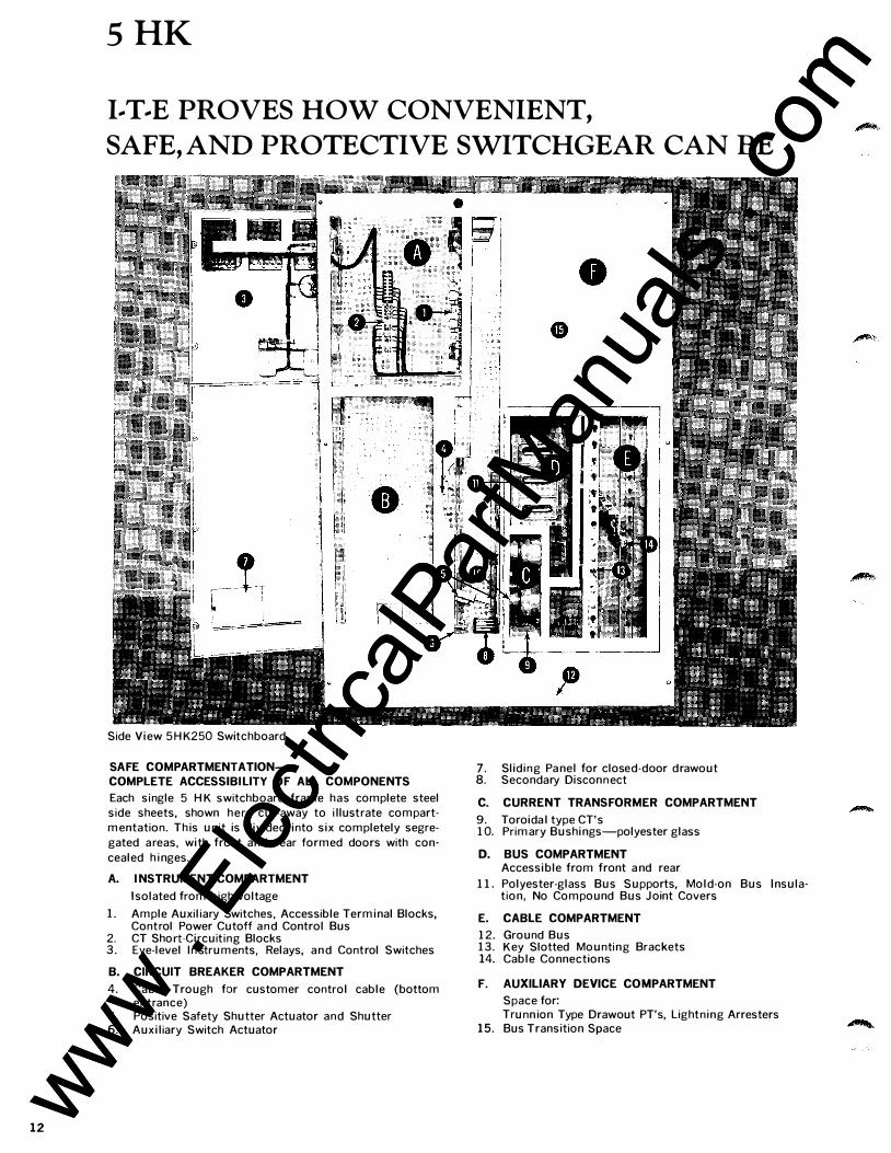
Side View 5 H K250 Switchboard
SAFE COMPARTMENTATION-COMPLETE ACCESSIBI LITY OF ALL COMPONENTS Each single 5 H K switchboard frame has complete steel
side sheets, shown here cut-away to i llustrate compart
mentation. This unit is divided into six completely segre
gated areas, with front and rear formed doors with con
cealed h i nges.
A. I NSTRUMENT COMPARTMENT Isolated from h igh voltage
L Ample Auxiliary Switches, Accessible Terminal Blocks, Control Power Cutoff and Control Bus
2. CT Short-Circuit ing Blocks 3. Eye-level I n struments, Relays, a n d Control Switches
B. CIRCUIT BREAKER COMPARTMENT 4. Cable Trough for customer control cable (bottom
entrance) 5. Positive Safety Shutter Actuator and Shutter 6. Auxiliary Switch Actuator
7. Sliding Pa nel for closed-door drawout 8. Secondary Disconnect
C. CURRENT TRANSFORMER COMPARTMENT 9. Toroidal type CT's 1 0. Primary Bushings-polyester glass
D. BUS COMPARTMENT Accessible from front a nd rear
1 1 . Polyester-glass Bus Supports, Mold-on Bus Insula-tion, No Compound Bus Joint Covers
E. CABLE COMPARTMENT 1 2. Ground Bus 1 3. Key Slotted Mounting Brackets 14. Cable Connections
F. AUXILIARY DEVICE COMPARTMENT Space for: Trunn ion Type Drawout PT's, Lightning Arresters
15. Bus Transition Space
www . El
ectric
alPar
tMan
uals
. com
www . El
ectric
alPar
tMan
uals
. com
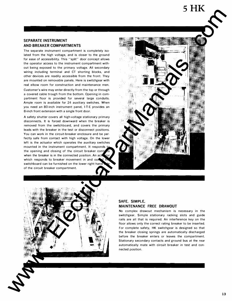
SEPARATE INSTRUMENT
AND BREAKER COMPARTMENTS
The sepa rate instrument compartment is completely iso
lated from the high voltage, and is closer to the ground
for ease of accessibi l ity. This "split" door concept a l lows
the operator access to the instrument compartment with·
out being exposed to the prima ry voltage. Al l secondary
wiring incl uding terminal and CT shorting blocks, and
other devices a re readi ly accessible from the front. They
a re mounted on remova ble panels. Here is switchgear with
real e lbow room for construction and mai ntenance men.
Customer's wire may enter directly from the top or through
a covered cable trough from the bottom. Opening in com
partment floor is provided for several la rge conduits.
Ample room is avai la ble for 24 a uxi liary switches. When
you need a n 80-inch instrument panel, 1-T-E provides an
8-inch front extension with a single front door.
A safety sh utter covers all high-voltage stationary primary
d isconnects. It is forced downward when the breaker is
removed from the switch board, and covers the primary
leads with the breaker in the test or d isconnect positions.
You can work in the circu it-breaker enclosure and be per
fectly safe from contact with high voltage. On the lower
left is the actuator which operates the a uxiliary switches
mounted in the instrument compartment. It responds to
the opening and closing of the circuit breaker contacts
when the breaker is in the connected position. An actuator
which responds to breaker movement in and out of the
switchboard can be fu rnished on the lower right hand side
of the circuit breaker compa rtment.
5HK
SAFE, SIMPLE,
MAINTENANCE FREE DRAWOUT
No complex d rawout mechanism is necessary in the
switchgear. Simple stationary racking slots and guide
rails are a l l that is req u ired. An interference key on the
floor a l lows only the correct rating breaker to be inserted.
For complete safety, HK switchgear is designed so that
the breaker closing springs a re a utomatica l ly discharged
before the breaker enters or leaves the compa rtment.
Stationary secondary contacts and ground bus at the rear
a utomatica l ly mate with circuit breaker in test and con
nected position.
13 www . El
ectric
alPar
tMan
uals
. com
www . El
ectric
alPar
tMan
uals
. com
14
5HK
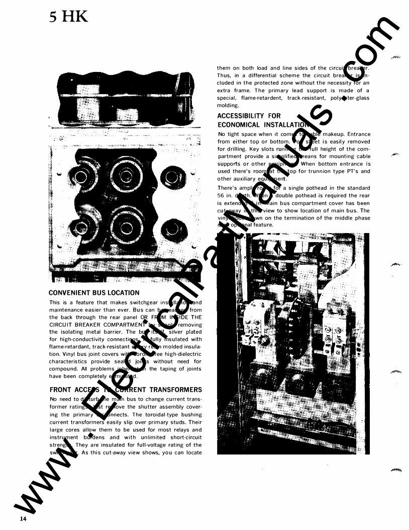
CONVENIENT BUS LOCATION
This is a feature that makes switchgear i n sta llation and
mai ntenance easier than ever. Bus can be reached from
the back through the rear panel OR FROM I N SIDE THE
C I RCUIT B R EAKER COMPARTM ENT by simply removing
the isolating metal barrier. The bus itself, silver plated
for high-conductivity connections, is fully insulated with
flame-retardant, track-resistant epoxy resin molded insula
tion. Vinyl bus joint covers with corona-free high-dielectric
characteristics provide sealed joints without need for
compound. All problems in herent in the taping of joi nts
h ave been completely e l iminated .
FRONT ACCESS TO CURRENT TRANSFORMERS
No need to d isturb the main bus to change current trans
former ratings. Just remove the shutter assembly cover
ing the primary d isconnects. The toroidal-type bush ing
current transformers easily slip over primary studs. Their
l a rge cores a l low them to be used for most relays a n d
instrument burdens a n d w i t h un l imited short-circuit
strength. They a re insulated for full-voltage rat ing of the
switchgear. As this cut-away view shows, you can locate
them on both load and l i ne sides of the c ircuit breaker.
Thus, in a differential scheme the c i rcuit breaker is in
c luded i n the protected zone without the necessity for a n
extra frame. T h e primary lead support is made of a
specia l , flame-reta rdent, track-resistant, polyester-glass
molding.
ACCESSIBILITY FOR
ECONOMICAL INSTALLATION
No tight space when it comes to cable makeup. Entra nce
from either top or bottom. Top sheet is easily removed
for d rilling. Key slots run n i ng the full height of the com
partment provide a simplified mea ns for mount ing cable
supports or other equipment. When bottom e ntrance is
used there's room at the top for trun n ion type PT's and
other auxiliary equipment.
There 's ample room for a single pothead in the standard
56 in. depth . When a double pothead is required the rear
is extended 8 in. Ma in bus compartment cover has been
cut away in this view to show location of main bus. The
vi nyl boot shown on the termi nation of the middle phase is a n optional feature.
www . El
ectric
alPar
tMan
uals
. com
www . El
ectric
alPar
tMan
uals
. com
COMPACT OUTSIDE
ACCESSIBLE INSIDE
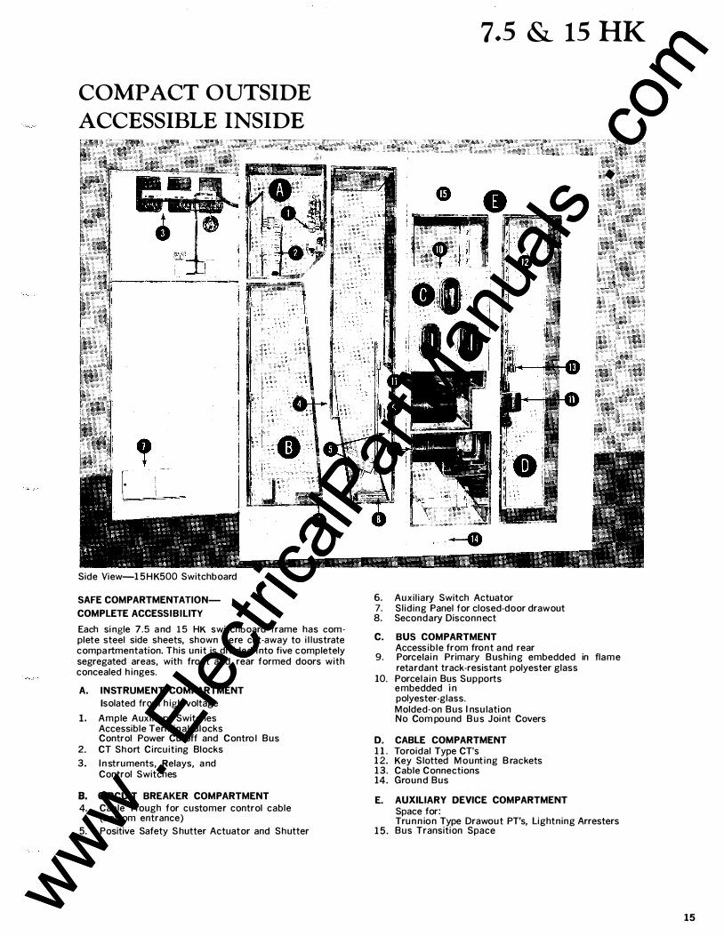
Side View-15HK500 Switchboard
SAFE COMPARTMENTATIONCOMPLETE ACCESSIBILITY
Each si ngle 7.5 a nd 15 HK switchboard frame has complete steel side sheets, shown here cut·away to i l lustrate compartmentation. This unit is divided i nto five completely segregated areas, with front a nd rear formed doors with concealed h inges.
A. INSTRUMENT COMPARTMENT Isolated from h igh voltage
1. Ample Auxi l iary Switches Accessible Terminal Blocks Control Power Cutoff and Contro l Bus
2. CT Short Circuiting Blocks
3. I n struments, Relays, a nd Control Switches
B. CIRCUIT BREAKER COMPARTMENT 4. Cable Trough for customer control cable
(bottom entrance)
5. Positive Safety S hutter Actuator and Shutter
7.5 & 15 HK
, , ;! •II II'
6. Auxil iary Switch Actuator 7. Sliding Panel for closed-door drawout 8. Secondary Disconnect
C. BUS COMPARTMENT Accessible from front a nd rear
9. Porcelai n Primary Bushing embedded in flame retardant track-resistant polyester glass
10. Porcela in Bus Supports embedded in polyester-glass. Molded-on Bus I nsu lation No Com pound B u s Joi nt Covers
D. CABLE COMPARTMENT 1 1 . Toroidal Type CT's 1 2. Key Slotted Mount ing B rackets 13. Cable Connections 14. Ground Bus
E.
15.
AUXILIARY DEVICE COMPARTMENT Space for: Tru n n ion Type Drawout PT's, lightning Arresters Bus Transition Space
15 www . El
ectric
alPar
tMan
uals
. com
www . El
ectric
alPar
tMan
uals
. com
16
7.5 & 15 HK
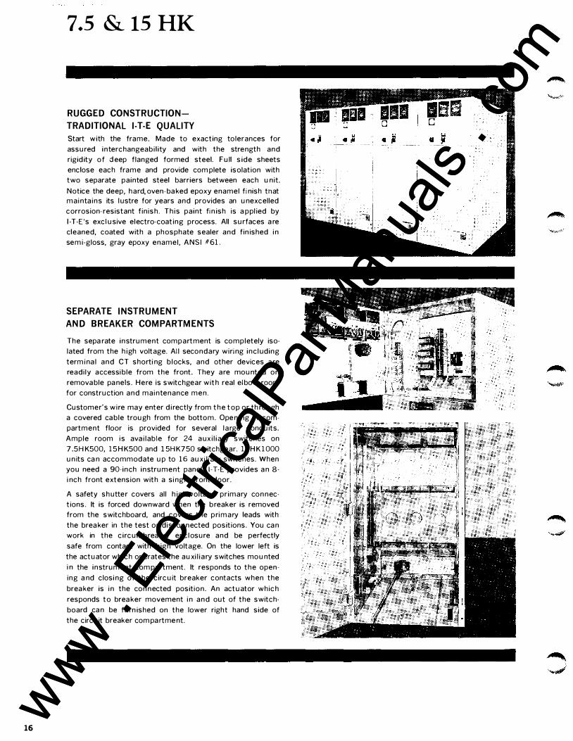
RUGGED CONSTRUCTION
TRADITIONAL 1-T-E QUALITY
Start with the frame. Made to exacting tolerances for
assured interchangeabi l i ty and with the strength and
rigid ity of deep flanged formed steel. Full s ide sheets
enclose each frame and provide com plete isolation with
two separate painted steel barriers between each unit.
Notice the deep, hard,oven·ba ked epoxy enamel finish tnat
mai nta ins its lustre for years and provides an unexcelled
corrosion-resistant f in ish. Th is paint fin ish is a ppl ied by
I ·T·E's exclusive electro-coating process. All surfaces a re
cleaned, coated with a phosphate sealer and fin ished i n
sem i-gloss, gray epoxy enamel , ANSI #61 .
SEPARATE INSTRUMENT
AND BREAKER COMPARTMENTS
The sepa rate instrument compartment is completely iso·
lated from the h igh voltage. All secondary wiring including
term i na l and CT shorti ng b locks, and other devices a re
readi ly accessi ble from the front. They are mounted on
remova ble pa nels. Here is switchgear with real el bow room
for construction and mai ntenance men.
Customer's wire may enter d i rectly from the top or th rough
a covered ca ble trough from the bottom. Open ing in com·
partment floor is provided for several large conduits.
Ample room is ava i lable for 24 aux i l iary switches on
7.5HK500, 1 5 H K500 and 15HK750 switchgear. 1 5 H K 1 000
un its ca n accommodate up to 16 auxiliary switches. When
you need a 90- inch instrument panel, I·T·E provides a n 8·
i nch front extension with a si ngle front door.
A safety shutter covers all h igh-voltage primary con nec·
tions. It is forced downward when the breaker is removed
from the switchboard, and covers the primary leads with
the brea ker in the test or discon nected positions. You ca n
work in the circuit-brea ker encl osure and be perfectly
safe from contact with h igh voltage. On the lower left is
the actuator wh ich operates the auxi l iary switches mounted
i n the instrument com pa rtment. It responds to the open·
ing a nd closi ng of the circuit breaker contacts when the
brea ker is i n the con nected position. An actuator which
responds to brea ker movement i n and out of the switch·
board ca n be furn ished on the lower right hand side of
the circuit breaker com pa rtme nt.
www . El
ectric
alPar
tMan
uals
. com
www . El
ectric
alPar
tMan
uals
. com
7.5 & 15 HK
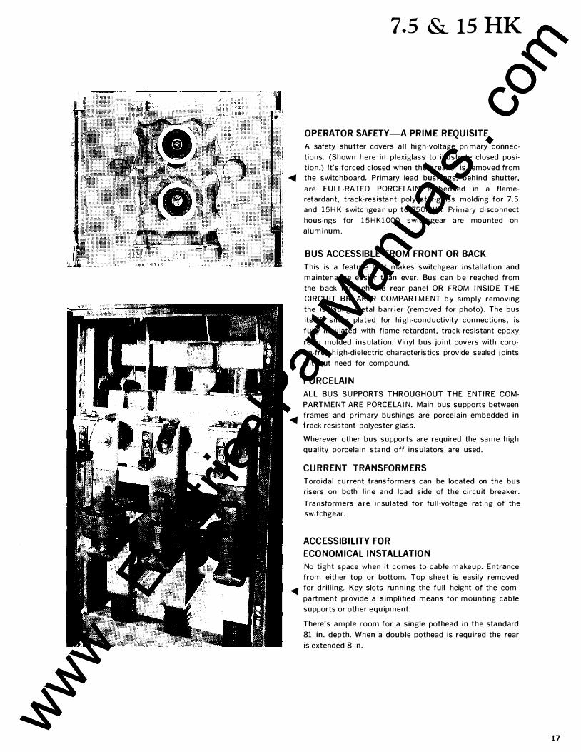
OPERATOR SAFETY-A PRIME REQUISITE
A safety shutter covers a l l h igh -voltage primary connec
tions. (Shown here in p lexiglass to i l lustrate closed posi·
t ion.) It's forced c losed when the breaker is removed from
� the switchboard. Primary lead bushings, beh ind shutter,
a re FULL·RATED PORCELA I N embedded in a flame
retardant, track-resista nt polyester-glass molding for 7 .5
and 1 5HK switc hgea r u p to 750MVA. Pri mary d isconnect
housings for 15HK1000 switchgear a re mounted on
alum i num .
BUS ACCESSIBLE FROM FRONT OR BACK
This is a feature that makes switchgea r instal lation and
m a i ntenance easier than ever. Bus can be reached from
the back through the rear panel OR FROM INSIDE THE
CI RCU IT B REAKER COMPARTMENT by sim ply removing
the isolating metal barrier (removed for photo) . The bus
itself, silver plated for high-conductivity con nections, is
fully insulated with flame-retardant, track-resistant epoxy
resin molded insulation. Vinyl bus joi nt covers with coro
na-free h igh-dielectric characteristics provide sealed joints
without need for com pound.
PORCELAIN
ALL BUS SUPPORTS THROUGHOUT T H E ENTIRE COM
PARTMENT ARE PORCELAIN. Main bus supports between
� frames and primary bushings are porcela in embedded i n track-resistant polyester-glass.
Wherever other bus supports are required the sa me h igh
qual ity porcela i n sta nd off i nsulators are used .
CURRENT TRANSFORMERS
Toroidal current transformers can be located on the bus
risers on both l i ne and load side of the circuit breaker.
Transformers are insulated for full-voltage rating of the
switchgear.
ACCESSIBILITY FOR
ECONOMICAL INSTALLATION
No tight space when it comes to cable makeup. Entrance
from either top or bottom. Top sheet is easily removed
� for dr i l l ing. Key slots run n i ng the full height of the com
partment provide a simpl ified means for m ounti ng cable
supports or other equipment.
There's a m ple room for a single pothead in the sta ndard
81 in . depth. When a double pothead is required the rear
is extended 8 i n .
17 www . El
ectric
alPar
tMan
uals
. com
www . El
ectric
alPar
tMan
uals
. com
5, 7.5 & 15 HK
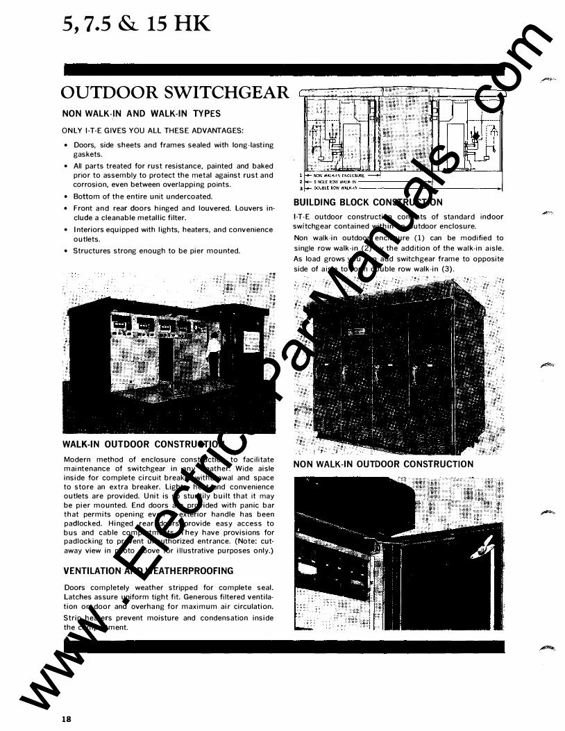
OUTDOOR SWITCHGEAR NON WALK-IN AND WALK-IN TYPES
ONLY 1-T-E G IVES YOU ALL THESE ADVANTAGES:
• Doors, side sheets and frames sealed with long-lasting gaskets.
• All parts treated for rust resistance, painted and baked prior to assembly to protect the metal against rust and corrosion, even between overla pping points.
• Bottom of the entire unit undercoated.
• Front a n d rear doors hinged and louvered. Louvers in
clude a cleanable metal l ic filter.
• Interiors equipped with l ights, heaters, and convenience
outlets.
• Structures strong enough to be pier mounted.
WALK-IN OUTDOOR CONSTRUCTION
Modern method of enclo.sure construction to faci l i tate mai ntenance of switchgear in any weather. Wide aisle inside for complete circuit breaker withdrawal and space to store an extra breaker. Lights, heat and convenience outlets are provided. Unit is so sturdily built that it may be pier mounted. End doors are provided with panic bar that permits opening even if exterior ha ndle has been padlocked. Hinged rear doors provide easy access to bus and cable compartments. They have provisions for padlocking to prevent unauthorized entrance. (Note: cut
away view in photo above for i l lustrative purposes only.)
VENTILATION AND WEATHERPROOFING
Doors completely weather stripped for complete seal.
Latches assure uniform tight fit. Generous fi ltered ventila
tion on door and overha ng for maximum air circulation.
Strip heaters prevent moisture and condensation inside
the compartment.
18
BUILDING BLOCK CONSTRUCTION
1-T-E outdoor construction consists of sta ndard indoor
switchgear contained within an outdoor enclosure.
Non walk-in outdoor enclosure ( 1 ) can be m odified to
single row walk-i n (2) by the add ition of the walk-i n a isle.
As load grows you can add switchgear frame to opposite
side of a isle to form double row walk-in (3) .
NON WALK-IN OUTDOOR CONSTRUCTION
www . El
ectric
alPar
tMan
uals
. com
www . El
ectric
alPar
tMan
uals
. com
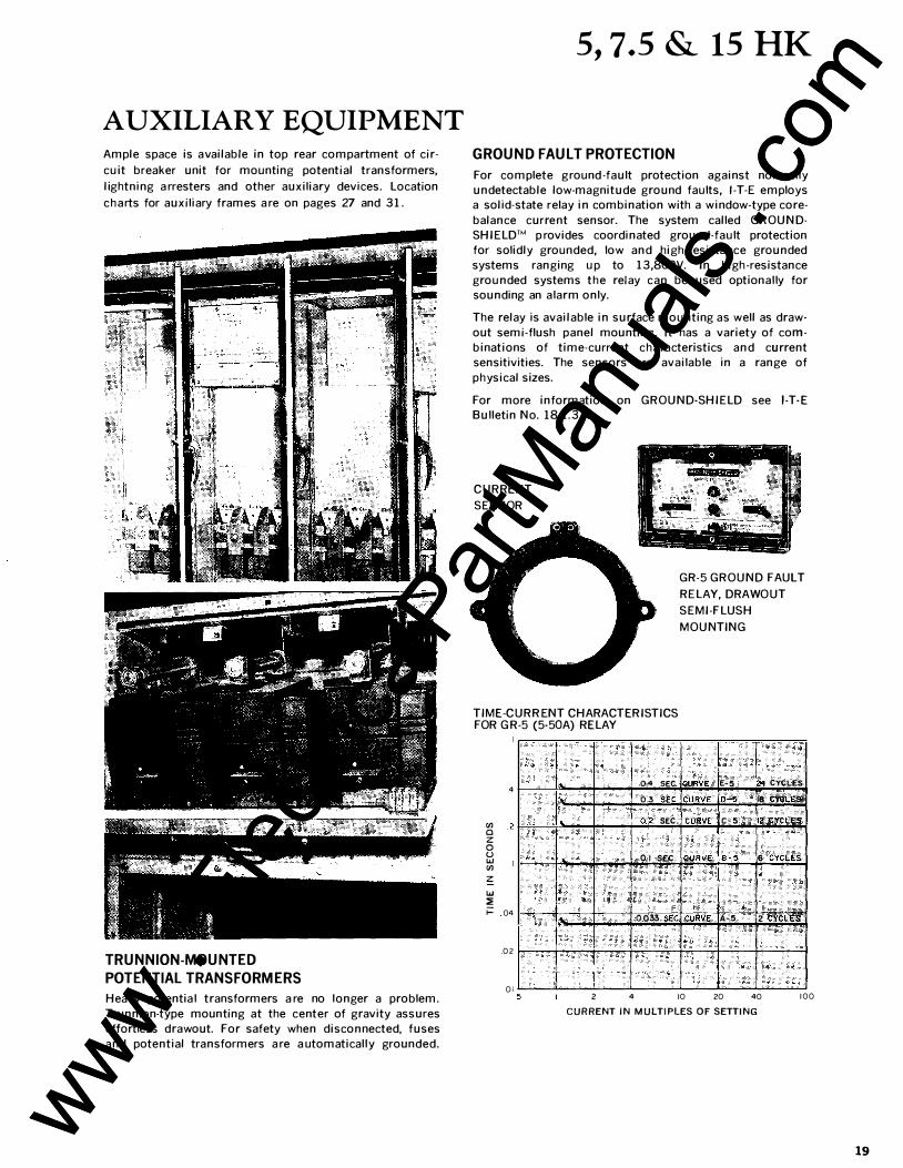
AUXILIARY EQUIPMENT Ample space is available in top rear compartment of cir
cuit breaker unit for mounting potential transformers,
lightning a rresters and other auxiliary devices. Location
charts for auxiliary frames a re on pages 27 and 31 .
TRUNNION-MOUNTED
POTENTIAL TRANSFORMERS
Heavy potentia l transformers a re no longer a problem.
Trunnion-type mounting at the center of gravity assures
effortless drawout. For safety when disconnected, fuses
and potential transformers a re a utomatical ly grounded.
5, 7.5 & 15 HK
GROUND FAULT PROTECTION
For complete ground -fault protection against normal ly undetectable low-magnitude ground faults, 1-T·E employs a solid·state relay in combination with a window-type core
balance current sensor. The system called GROUND·
SHIELD'M p rovides coordinated ground-fault protection
for solidly grounded, low and high-resistance grounded
systems ranging up to 1 3,800V. In high-resistance
grounded systems the relay can be used optional ly for sounding an a larm only.
The relay is available in surface mounting as well as draw·
out semi-flush panel mounting. It has a variety of com
binations of time-current characteristics and current
sensitivities. The sensors a re available in a range of
physical sizes.
For more information on GROUND-SHIELD see 1-T-E Bulletin No. 18. 1 . 3 - 3
C U RRENT
SENSOR
TIME-CURRENT CHARACTERISTICS FOR G R-5 (5-50A) RELAY
4 0.4 SEC. . 0.3 SEC.
rJl Q2 SEC.
c z 0 u .., 0.1 SEC. rJl z .., ::;: ;:: 04 0.033 SEC
02
01
GR-5 GROUND FAULT
RELAY, DRAWOUT
SEMI-FLUSH
MOUNTING
CIJF!\IE E-5 l CYCLES
CURVE D-5 J8 CYcLES
CURVE c-5 112 CYCLES
CURVE B-5 6 CYCLES
CURVE A-5 2 CYCLE;$.
5 2 4 10 20 40 100
CURRENT IN MULTIPLES OF SETTING
19 www . El
ectric
alPar
tMan
uals
. com
www . El
ectric
alPar
tMan
uals
. com
5, 7.5 & 15 HK
-1 -�
�
Table 2
Nominal System
Voltage, kV
2.4 4.16
7.2 13.8
20
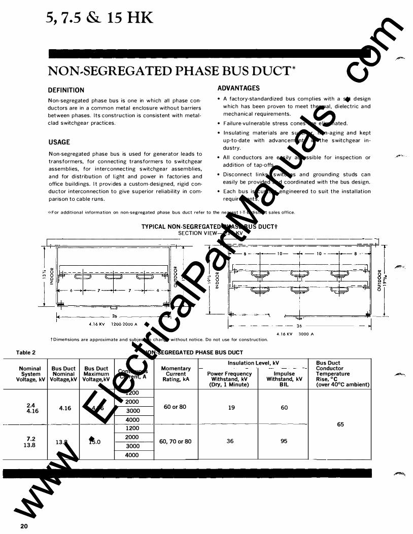
NON .. SEGREGATED PHASE BUS DUCT*
DEFINITION
Non-segregated phase bus is one in which all phase con
ductors are in a common meta l enclosure without ba rriers
between p hases. Its construction is consistent with meta l
clad switchgea r practices.
USAGE
Non-segregated phase bus is used for generator leads to
transformers, for con necti ng transformers to switchgear
assembl ies, for interconnecting switchgea r assembl ies,
a nd for d i stribution of light and power in factories and
office bui ld i ngs. I t p rovides a custom-designed, rigid con
ductor i ntercon nection to give superior rel iab i l ity in com
parison to ca ble runs.
ADVANTAGES
• A factory-sta ndardized bus com pl ies with a set d esign
w h ich has been p roven to meet thermal , d i electric a nd
mecha nical requirements.
• Fai lure-vul nerab le stress cones a re e l i m i nated.
• I n sulati ng mater ia ls are superior, non-aging a n d kept
up-to-date with advancements in the switchgear i n
dustry.
• Al l conductors a re easily accessi b le for inspection or
add i tion of tap-offs.
• Disconnect l i nks, switches and grounding studs ca n
easi ly be provided and coord i nated with the bus design.
• Each bus is custom engineered to suit the instal lation
requirements.
�:�For additional information on non-segregated phase bus duct refer to the nearest 1-T-E district sales office.
TYPICAL NON-SEGREGATED PHASE BUS DUCTt SECTION V I EW-4.16 KV
,-------------------1 r---------------------,
a: 0 0 Q �
7
-�-- 10--...k--- 10 __ ,.... __
36 4.16 KV 3000 A
tDimensions are approximate and subject to change without notice. Do not use for construction.
NON-SEGREGATED PHASE BUS DUCT
Insulation Level, kV Bus Duct Bus Duct Bus Duct Continuous Momentary Conductor Nominal Maximum Current, A Current Power Frequency Impulse Temperature
Voltage,kV Voltage,kV Rating, kA Withstand, kV Withstand, kV Rise, °C (Dry, 1 Minute) B IL (over 40°C ambient)
1200 2000
4.16 4.76 3000 60 or80 19 60
4000 1200 65
2000 60,70 or80 36 13.8 15.0 95
3000 4000
www . El
ectric
alPar
tMan
uals
. com
www . El
ectric
alPar
tMan
uals
. com
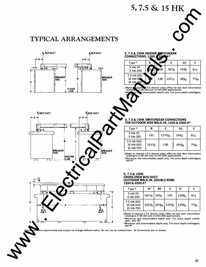
TYPICAL ARRANGEMENTS
f Ci
A
L
D
II ..--�16 r
!'-BUS DUCT
I . I-E
I
I I \I
·�:r BREAKER SIDE C
BREAKER SIDE
j FLOOR LINE
B C
GROUND LINE
!-D-..
I I� *E�
B
l
I
BUS DUCT
� 1-oof
I
BREAKER SIDE
BREAKER SIDE
r=- 1-E £-f Fl
D I A G
B B G 11
�-�=��
S
-
T
------IL�------------�IL=--------�=��\�
5, 7.5 & 15 HK
5, 7.5 & 15HK INDOOR SWITCHGEAR CONNECTIONS, 1200 & 2000 A*
Typed A B c
5 H K-75 5 HK-250 80 1 06 92Va
7.5 H K-500 15 H K-500 90 1 26 1 101h 15 H K-750
Dt
13%
32%6
E
61h
71�6
dRefer to nea rest 1-T-E district sales office for bus duct information relating to 5 HK-350 and 15 H K-1000 applications.
tMinimum and intermediate depth only. For extra depth switchgear, add 8".
5, 7.5 & 15HK SWITCHGEAR CONNECTIONS FOR OUTDOOR NON WALK-IN, 1200 & 2000 A*
Typed B c Dt
5 H K-75 13 1 1 1 71�6 1 6%
5 H K-250
7.5 H K-500 15 H K-500 1 5 1% 136 451%s 15 H K-750
E
61h
71�6
dRefer to nearest 1-T-E district sales office for bus duct information relating to 5 HK-350 and 15 H K·1000 applications.
tMinimum and intermediate depth only. For extra depth switchgear, add 8".
5, 7.5& 15HK CROSS-OVER BUS DUCT (OUTDOOR WALK-IN, DOUBLE ROW) 1200 & 2000 A*
Typed Ao Bt c
5 H K-75 1 6 1 1,4 1 6% 1 05
5 H K-250
7.5 H K-500 15 H K-500 1 52% 451%6 1 15%
15 H K-750
D E
1 22f16 61h
135fls 71�6
dRefer to nearest 1-T·E district sales office for bus duct information relating to 5 HK-350 and 15 H K-1000 applications.
0Minimum and intermediate d epth only. For extra depth switchgear, add 16''.
tMinimum and intermediate depth only. For extra depth switchgear, add 8".
*Dimensions a re approximate and subject to change without notice. Do not use for construction. All dimensions are in inches.
21 www . El
ectric
alPar
tMan
uals
. com
www . El
ectric
alPar
tMan
uals
. com
22
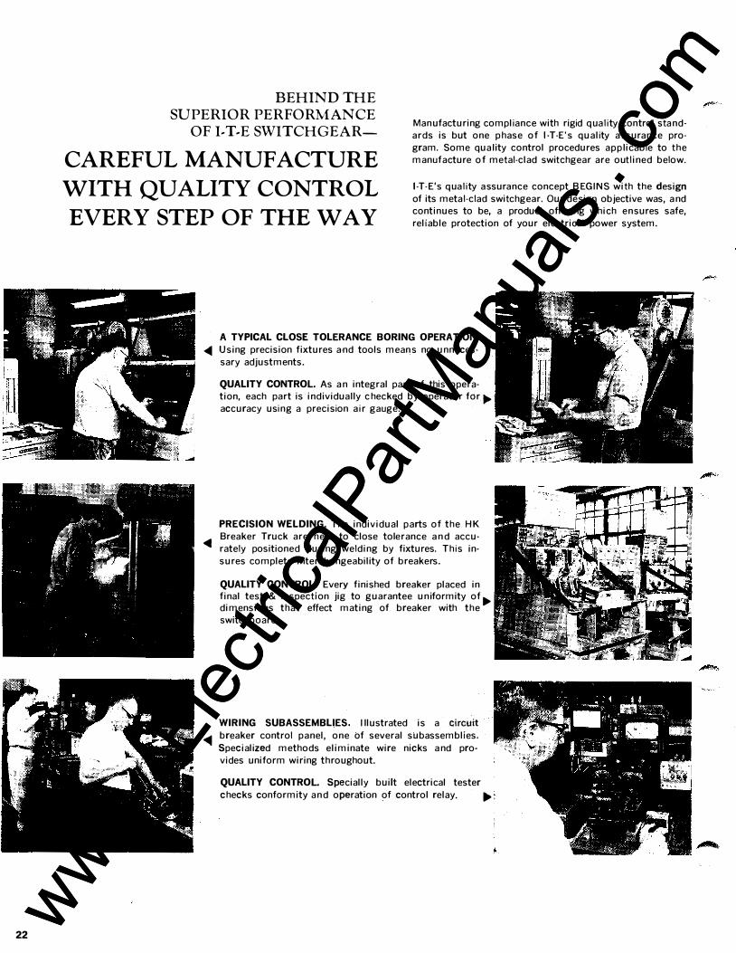
BEHIND THE
SUPERIOR PERFORMANCE
OF I-T-E SWITCHGEAR-Manufacturing compliance with rigid qual i ty control sta ndards is but one p hase of 1-T-E's quality a ssurance pro
gram. Some quality control procedures applicable to the manufacture of metal-clad switchgear are outlined below. CAREFUL MANUFACTURE
WITH QUALITY CONTROL
EVERY STEP OF THE WAY
1-T-E's qual i ty assurance concept B EG I N S with the design
of its metal-clad switchgear. Our design objective was, a nd continues to be, a product offering which ensures safe,
reliable protection of your electrical power system.
A TYPICAL CLOSE TOLERANCE BORING OPERATION. <1111 Using precision fixtures a-nd tools mean s no unneces
sary adjustments.
<1111
QUALITY CONTROL As a n integral part of this operation, each part is individually c hecked by operator for ... accuracy usi ng a precision a i r gauge.
PRECISION WELDING. The individual parts of the H K
Breaker Truck are held to close tolerance a n d accu-
rately positioned during welding by fixtures. Th is in
sures complete intercha ngeability of breakers.
QUALITY CONTROL. Every finished breaker placed in final test & inspection jig to guarantee uniformity of ... dimensions that effect mating of breaker with the
switchboard.
WIRING SUBASSEMBLIES. I llustrated is a circuit <1111 breaker control panel, one of several subassemblies.
Specialized methods eliminate wire nicks a nd pro
vides uniform wiring throughout.
QUALITY CONTROL Specially built electrical tester
checks conformity a n d operation of control relay. ...
www . El
ectric
alPar
tMan
uals
. com
www . El
ectric
alPar
tMan
uals
. com
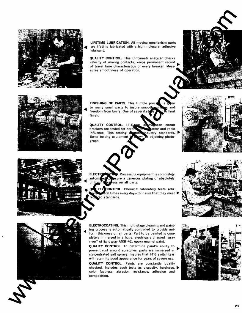
LIFETIME LUBRICATION. All moving mechanism parts � are lifetime lubricated with a high-molecular adhesive
lubricant.
QUALITY CONTROL. This Cincinnati analyzer checks velocity of moving contacts, keeps permanent record of travel time characteristics of every breaker. Meas- .... sures smoothness of operation.
FINISHING OF PARTS. This tumble process is given to many small parts to i ns u re smooth su rfaces and � freedom from bu rrs. One of several steps prior to final finish.
QUALITY CONTROL. 1 -T-E HK a i r-magnetic c i rcuit b reakers a re tested for corona, power factor and radio i nfluence. This testing exceeds industry standards. .... Some testing equ i pment is shown i n adjoining photograph.
ELECTROPLATING. Processi ng eq ui pment is completely
� automated to i nsure a generous plating of a bsolutely u niform thickness on al l parts.
QUALITY CONTROL. Chemical laboratory tests solutions several t imes every day-to insure that they meet � requ i red standards.
ELECTROCOATING. This m ulti-stage cleaning and paint-<11111 i ng process is automatically controlled to provide u n i
form thickness on al l parts. Part to b e painted is completely immersed i n a huge, electrically charged "gray river" of light gray ANSI #61 epoxy enamel paint. QUALITY CONTROL. To determi n e pai nt's abi lity to prevent rust around scratches, parts are i mmersed in .... concentrated salt sprays. I ns u res that 1-T-E switchgear will retai n its good appearance for years of severe use. QUALITY CONTROL. Paints a re constantly qual ity checked. Includes such tests as viscosity, hardness, .... color fastness, a brasion resistance, adhesion a nd composition.
23 www . El
ectric
alPar
tMan
uals
. com
www . El
ectric
alPar
tMan
uals
. com
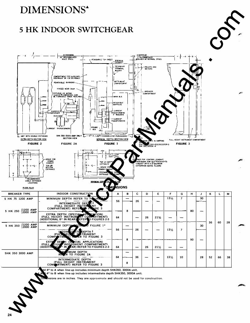
DIMENSIONs·
5 HK INDOOR SWITCHGEAR
� I I
!SHK 350·3000 AMP ONLY �_..--:3-.... 4 . 1 LB/FT. CHANNELS (BY PURCHASER)� NOTES
RELAYS AND METERS
BREAKER
COMPARTMENT
FLOOR LINE
!!... UNIT WITH DOUBLE POTHEADS
EXl'JtA DEPTH-SECTlON VIEW SECTION VIEW MINIMUM DEPTH-SECTION VIEW (i) MAXIMUM UNITS IN SHIPP!NG SECTION '
FULL HEIGHT INSTRUMENT COMPARTMENT
FIGURE 2
RECOMMENDED CABLE ENTRANCE
LOCATIONS
SPACE FOR POWER
CONDUIT
TOP OR BOTTOM ENTRANCE
FIGURE 2A FIGURE 1
DIMENSIONS
BREAKER TYPE
5 H K 75 1200 A M P
5 H K 250 f1200 AMP 2000 AMP
5 H K 350 f1200 AMP 2000 AMP
5 H K 350 3000 A M P
I N DOOR CONSTRUCTION
M I N I M U M DEPTH REFER TO FIGURE 1 *
I NTERMEDIATE DEPTH t (FULL HEIGHT I NSTRUMENT
COM PARTMENT) REFER TO FIGURE 3
EXTRA DEPTH (SPECIAL APPLICATION) (FULL HEIG HT INSTRUMENT COMPARTMENn
(ADDITIONAL 8" IN REAR) REFER TO FIGU RES 2-3
M I N I M U M DEPTH REFER TO FIGURE 1 *
I NTERMED IATE DEPTH f (FULL HEIGHT INSTRUMENT
COMPARTMENn REFER TO FIGURE 3
EXTRA DEPTH (SPECIAL APPLICATION) (FULL H E I G HT INSTRUM ENT COM PARTMENn
(ADDITIONAL 8" IN REAR) REFER TO FIGURES 2-3
M I N I M U M DEPTH REFER TO FIGURE 2A
INTERMEDIATE DEPTH (FULL HEIGHT I NSTRUMENT
COMPARTMENn REFER TO FIGURE 3
A B
-56 r--
8
64
-56 '---
8
64
-
64 r---8
c
26
-
26
-
36
• Add 4" to A when line-up includes minimum depth 5HK350, 3000A unit.
5HK 75, 250,350-1200 6 2000A·5 5HK 350, 3000A -4
D E F
1 3 1h - -
26 2 1 'h -
- - 1 3 'h
26 2 1 'h -
- - 13 'h
t Add 4" to B when line-up includes intermediate depth 5H K350, 3000A unit .
.& Dimensions a re in inches. They a re approximate and should not be used for construction.
24
FIGURE 3
G H J 7 30
f---
80 -
-
30
7 �
90 -
-
10 28
K L M
36 60 28
52 66 38
www . El
ectric
alPar
tMan
uals
. com
www . El
ectric
alPar
tMan
uals
. com
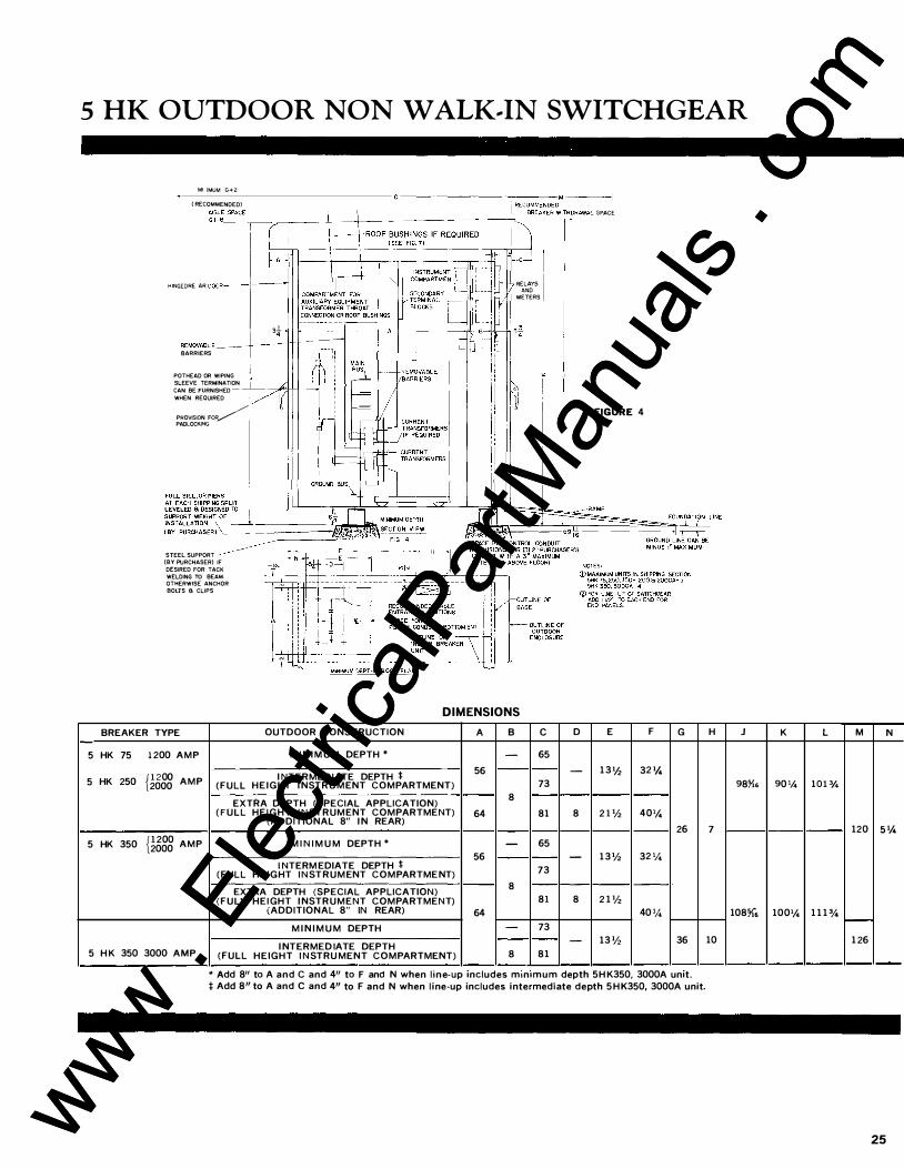
5 HK OUTDOOR NON WALK .. IN SWITCHGEAR
MINIMUM G+2
( RECOMMENDED) ----------..1-,-
R-EC
-0-
MM_E_N_DE-DM-------1
, _,. ,, :_
s
_
P
.
_
c
E
_
I 'c__-'.,---L--+---"-E_E_'_'c_, 7-'-------.c---mi, __ .----'�,�1'-""
I ,, :':1::
REMOVABLE_-+� BARRIERS I
POTHEAD OR WIPING 1
SLEEVE TERMINATION CAN BE FURNISHED WHEN REQUIRED
PROVISION FOR/ PADLOCKING
FIGURE 4
STEEL SUPPORT (BY PURCHASER) IF DESIRED FOR TACK WELDING TO BEAM. OTHERWISE ANCHOR BOlJS a CLIPS
DIMENSIONS
5
5
BREAKER TYPE
HK 75
HK 250
1 200 AMP
{ 1 200 AMP 2000
5 HK 350 {1 200 AMP 2000
5 H K 350 3000 AMP
OUTDOOR CONSTRUCTION A B
M I N I M U M DEPTH * -I NTERMEDIATE DEPTH l 56
(FULL HEIGHT I NSTR U MENT COMPARTMENT) EXTRA DEPTH (SPECIAL APPLICATION) 8
(FULL HEIGHT I N STRUMENT COMPARTMENT) 64 (ADDITIONAL 8" I N REAR)
M I N I M U M DEPTH * -I NTERM EDIATE DEPTH l 56
(FULL HEIGHT I N STRUMENT COMPARTMENT) EXTRA DEPTH (SPECIAL APPLICATION) 8
(FULL HEIGHT I NSTRUMENT COMPARTMENT) (ADDITIONAL 8" IN REAR) 64
M I N I M U M DEPTH -I NTERMED IATE DEPTH
(FULL HEIGHT I NSTRU MENT COMPARTMENT) 8
c D E F
65 - 1 3 1h 32 11. 73
81 8 2 1 % 40'1.
65 - 1 3 % 32 11. 73
81 8 2 1 % 40 '1.
73 - 13 '12 81
G
26
36
• Add 811 to A and C and 411 to F and N when l one-up oncludes monomum depth 5H K350, 3000A unot. t Add 8" to A and C and 4" to F and N when l ine-up includes intermediate depth 5 H K350, 3000A unit.
H J
98�.
7
108X'o
10
K L M N
90% 101 %
120 s •;.
10011. 1 1 1 % -1 26
25 www . El
ectric
alPar
tMan
uals
. com
www . El
ectric
alPar
tMan
uals
. com
26
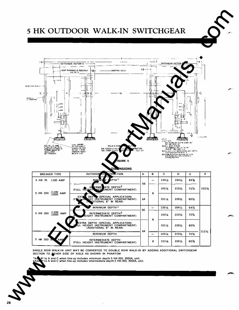
5 HK OUTDOOR WALK .. IN SWITCHGEAR
BREAKER TYPE
5 H K 75 1 200 AMP
5 H K 250 {1 200 AMP 2000
5 H K 350 {1 200 AM P 2000
5 HK 350 3000 AMP
FIGURE 5
DIMENSIONS
OUTDOOR CONSTRUCTION
M I N I M U M DEPTH *
I NTERMEDIATE DEPTH * (FULL HEIGHT I NSTRU MENT COMPARTMENT)
EXTRA DEPTH (SPECIAL APPLICATION) (FULL HEIGHT I NSTRUMENT COMPARTMENT)
(ADDITIONAL 8" IN REAR)
M I N I M U M DEPTH *
INTERMEDIATE DEPTH * (FULL HEIGHT I NSTRUMENT COMPARTMENT)
EXTRA DEPTH (SPECIAL APPLICATION) (FULL H E IGHT I NSTRUMENT COMPARTMENT)
(ADDITIONAL 8" IN REAR)
M I N I M U M DEPTH
I NTERMEDIATE DEPTH (FULL HEIGHT I NSTRUMENT COMPARTMENT)
A B c D
- 1351,4 194'/:z 56
143 % 210'/:z 8
64 151 % 226'/:z
- 135 1,4 194'12 56
143% 210'/:z 8
151 % 226'/:z
64 - 143 % 210'/:z
8 1 5 1 1,4 226'/:z
E
64'l's
72'l's
80'l's
64%
72'l's
80%
72'l's
80'l's
SINGLE ROW WALK-I N U N IT MAY BE CONVERTED TO DOUBLE ROW WALK- I N BY ADDING ADDITIONAL SWITCHGEAR SECTION TO OTHER S I DE OF AISLE AS SHOWN IN PHANTOM *Add 8" to A and C when line-up includes minimum depth 5 H K-350, 3000A, unit. *Add 811 to A and C when line-up includes intermediate depth 5 H K-350, 3000A, unit.
F
1023,4
1 1 2 %
www . El
ectric
alPar
tMan
uals
. com
www . El
ectric
alPar
tMan
uals
. com
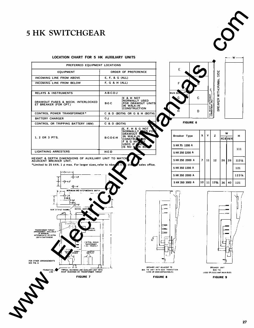
5 HK SWITCHGEAR
LOCATION CHART FOR 5 HK AUXILIARY UNITS
PREFERRED EQU I PMENT LOCATIONS
EQU IPMENT ORDER OF PREFERENCE
I NCOM ING LINE FROM ABOVE E, F, & G (ALL) I NCOM I N G L I N E FROM BELOW F, G & H (ALL)
RELAYS & I NSTRUMENTS A·B·C·D·J fE & H NOT DRAWOUT FUSES & M ECH. I NTERLOCKED NORMALLY USED ET BREAKER (FOR CPT.) B-E·C (OR DRAWOUT U NITS
IN WALK-I N CONSTRUCTION
CONTROL POWER TRANSFORMER * C & D (BOTH) OR G & H (BOTH) BATTERY CHARGER C-J
CONTROL OR TRIPPING BATTERY (48V) c & D (BOTH) r· F, H & G NOT N ORMALLY USED FOR DRAWOUT U N ITS
1, 2 OR 3 PT'S. B·C·D·E·H IN WALK- I N l CONSTRUCTION F & G MAY B E USED I F THERE IS NO MAIN BUS
LIGHTN ING ARRESTERS H·E·D
H E IGHT & DEPTH D I M ENSIONS OF AUXILIARY U N IT TO MATCH ADJACENT BREAKER U NIT. * Limited to 25 kVA. 1 t/1 max. For larger sizes, refer to nearest 1-T-E d istrict sales office.
TRANSFORMER THROAT ARRANGEMENT AVAILABLE
IN MINIMUM, INTERMEDIATE OR EXTRA
DEPTH SWITCHGEAR
FOR OTHER ARRANGEMENTS SEE FIG. 6
·� DEPTH
I w
l I
I 26
l
E
F -MAIN SUS__...--
G
H
FIGURE 6
Breaker Type
5 HK 75 1200 A
5 HK 250 1200 A
5 HK 250 2000 A
5 HK 350 1200 A
5 HK 350 2000 A
5 HK 350 3000 A
FOUNDATION�L INCOMING LINE AUXILIARY UNIT WITH
BREAK(R UNIT ADJACENT TO LJNE ROOF BUSHINGS OR TRANSFORMER THROAT
FIGURE 7
aus TIE UNIT WITH BUS TRAN SITION
(1200 OR 2000 AMJ?MAINBUS)
FIGURE 8
A
B
c
0
X
7
10
;) �� � z � 0 � � �i � "' • I � 2 � 0 ""
w y z AC.S AU}(
11
1 1
12 26
13% 36
BREAKER UNIT
BUS TIE
26
40
( 1200 00 2000 AMP. MAtN BUS)
FIGURE 9
H
1 1 1
113 V..
121
1 2 3 V..
1 2 1
27 www . El
ectric
alPar
tMan
uals
. com
www . El
ectric
alPar
tMan
uals
. com
••
28
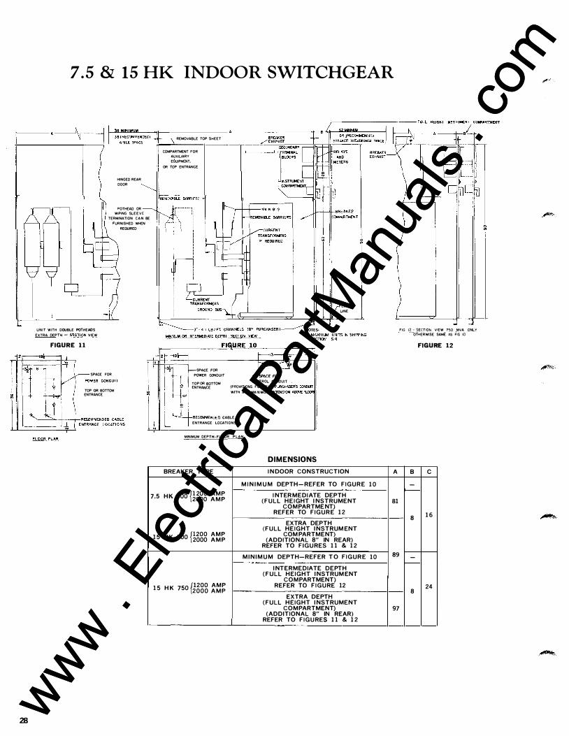
7 . 5 & 15 HK INDOOR SWITCHGEAR
UNIT WITH DOUBLE POTHEADS EXTRA DEPTH � SECTION VIEW
FIGURE 1 1
HINGED REAR DOOR
POTHEAD OR WIPING SLE E V E
TERMINATION C A N BE FURNISHED WHEN
REQUIRED
SPACE FOR
TOP OR BOTTOM ENTRANCE
REMOVABLE TOP SHEET
COMPARTMENT FOR AUXILIARY E6UlPMENT,
OR TOP ENTRANCE
f*i--�SPACE FOR
FLOOR UNE
: + l 1: POWER CONDUIT I I � TOP OR BOTTOM CONTROL CONDUIT
I rtl ENTRANCE ��:'!'���=�:�'� �;:�;.SE:;,�rr �RECOMMENDED CABLE
___ _j ENTRANCE LOCATIONS
MINIMUM DEPTH-FLOOR PLAN
BREAKER TYPE
p200 AMP 7.5 HK 500 2000 AMP
15 H K 500 p200 AMP 2000 AMP
1 5 H K 750 {1200 AMP 2000 AMP
DIMENSIONS
I N DOOR CONSTRUCTION
M I N I M U M DEPTH- REFER TO FIGURE I NTERMEDIATE DEPTH
(FULL HEIGHT I NSTRUMENT COMPARTMENT)
REFER TO FIGURE 12 EXTRA DEPTH
(FULL HEIGHT I NSTRUM ENT COM PARTMENT)
(ADDITIONAL 8" IN REAR) REFER TO FIGURES 1 1 & 12
M I N I M U M DEPTH-REFER T O FIGURE I NTERMEDIATE DEPTH
(FULL HEIGHT I NSTRUM ENT COMPARTMENT)
REFER TO FIGURE 12 EXTRA DEPTH
(FULL HEIGHT I NSTRUMENT COMPARTMENT)
(ADDITIONAL 8" IN REAR) REFER TO FIGURES 1 1 & 1 2
10
10
, , �J .J
A
81
89
97
FIG 12 - SECTION VIEW 750 M�A ONLY OTHERWISE SAME AS FIG 10
FIGURE 12
B c -
I--
8 1 6
--8
24
www . El
ectric
alPar
tMan
uals
. com
www . El
ectric
alPar
tMan
uals
. com
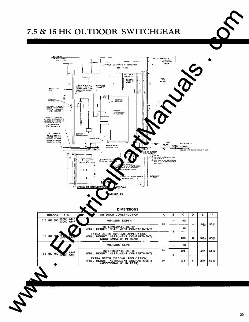
7.5 & 15 HK OUTDOOR SWITCHGEAR
-�,,� .. ·��M�M�����-;-------------------- c ------------------------�--������--� 54"(RECOMMENDEO) I 126" ( RECOMMENDED) I AISLE S��C�E
-_.t-----}-----�----+---:::::::::--.:::==��===-
-----to::::::--t BREAKER l WITHDRAWAL
! I I SPACE ( �/ROOF BUSHINGS IF REQUIRED 1 i l r ( SEE FIG 1 6 )
�' \ ! I 111 ,j L_T j_l i � i��������::r �- �n� f--·_j �j
l l r-tt-----+--i-RELAYS SECON�:�
l _ -� AND
1-c==="ic::--+--------+--A I I ������.� L_ rL�� •i METERs
COMPARTMENT FOR REMOVASLE � I n � r�����l���:��Tr::��:��---- � m L,=:
II) V
MAIN
PROVISIONS 0 �,r-- - I BUS i _.. �EMO
VABLE FOR PADLOCKING� )K j t--'"" BARRIERS �����,.l+2l, :: tJI POTHEAD OR WIPING r--CAN BE FURNISHED
SLEEVE TERMINATION � I WHEN REQUIRED , t r- ---, . _ f-- ��:��1RMERS I : Di_ _ _j� IF REQUIRED
FULL SILL, OR PIERS I l -LEVELED B DESIGNED TO AT EACH SHIPPING SPLIT, �' SUPPORT WEIGHT OF
INSTALLATION n ::T:::��:�:���\ ��:��RMERS '------:£, DESIRED FOR TACK WELDING TO BEAM GROUND BUS OTHERWISE ANCHOR BOLTS 6 CLIPS
6� J 1 MINIMW DEPTH J I
�· 0 0
RAMP r---FOUNOATION Ll
L:=�=====s�·�'.if��';ft. ·-��;l··•�.;��.u.t1\:·\ SECTION VI
EW L__GROUNO LINE CAN BE MINUS I" MAX.
BREAKER TYPE
OUTLINE OF OUTDOOR E F I 13� �NCLOSURE
-- --- __ ------------- ---- ---- - - -- NOTES· ----- -�--------------- - - - - - ------- - ---- - -1 '1 <D MAXIMUM UNITS IN SHIPPING
·--�- r----------,�1"' I SECTION IS 4 , 3--t-D-j RECOMMENDED CABLE �-----j_____L""' : I : , (%) FOR LINE-UP OF SWITCHGEAR '
I : 2+- � -· ENTRANCE LOCATIONS LSPA.CE FOR I : I ' ADO 1 112" TO EACH END FOR' I ' : CONTROL CONDUIT : • I END PANEt.S
1 CONDUIT WITH A 3" MAXIMUM : , 'I _y- {PROVISIONS FOR (3J 2� PURCHASERS •1. I •1 I : t-tt_-+-- ' EXTENSION ABOVE FLOOR) 1 •1 I ' ' I ' i I T OUTLINE OF INOOOR � i-1--0UTLINE OF : ' +---+-·-+-'- SREAKER UNIT
_\.li I ; BASE b-�:.==:) ______ ��r!1;������,�------------------ U 1 MINIMUM OR INTERMEDIATE DEPTH - FLOOR PLAN
FIGURE 13
DIMENSIONS
OUTDOOR CONSTRUCTION A B {1200 A M P 7 .5 H K 500 2000 A M P M I N I M U M DEPTH -
15 H K 500 fl200 A M P 2000 A M P
1 5 H K 750 fl200 A M P 2000 A M P
I NTERMEDIATE DEPTH (FULL HEIGHT I NSTRUMENT COM PARTMENT)
EXTRA DEPTH (SPECIAL APPLICATION) (FULL HEIGHT I NSTRUMENT COMPARTMENT)
(ADDITIONAL 8" IN REAR)
M I N I M U M DEPTH
I NTERMEDIATE DEPTH (FULL HEIGHT I NSTRUMENT COM PARTM ENT)
EXTRA DEPTH (SPECIAL APPLICATION) (FULL HEIGHT I NSTRUMENT COMPARTMENT)
(ADDITIONAL 8" I N REAR)
81
8
-89
8
97
c D E
90 - 10'1.
98
106 8 18'1.
98
106 - 10 1h
114 8 18'1.
F
55 1/4
631/.o
551/4
63 1/4
29 www . El
ectric
alPar
tMan
uals
. com
www . El
ectric
alPar
tMan
uals
. com
30
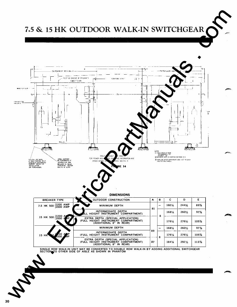
7.5 & 15 HK OUTDOOR W ALK .. IN SWITCHGEAR
?<�.:(·�:� (_
'OCL"lL OR P"RS� •. • S1<EC SUPPORT
" EAC" S"'"'" "'"'· � \BT PURC .. SERJ "
LEVELED a DESIGNED TO DESIRED FOR TACK
SUPPORT WEIGHT OF WELDING TO BEAM INSTALLATION OTHERWISE ANCHOR
(8Y PURCHASE:R} SOLTS a CLIPS
7.5
BREAKER TYPE
HK 500 p200 A M P 2000 A M P
15 H K 500 {1200 AMP 2000 AMP
15 H K 750 p200 AMP 2000 AMP
(FULL
SINGLE 8 DOUBLE ROW WALK-IN
FOR POWER AND CONTRCL ENTRANCE INFORMATION AND
OTHER DESIGN CHARACTERISTICS SEE FIG 13
FIGURE 14
DIMENSIONS
OUTDOOR CONSTRUCTION
M IN I M U M DEPTH
I NTERMEDIATE DEPTH H EIGHT I NSTRUMENT COMPARTMENT)
EXTRA DEPTH (SPECIAL APPLICATION) (FULL HEIGHT I NSTRUMENT COMPARTMENT)
(ADDITIONAL 8" IN REAR) M I N I M U M DEPTH
I NTERMEDIATE DEPTH (FULL HEIGHT I N STRUMENT COMPARTMENT)
EXTRA DEPTH (SPECIAL APPLICATION) (FULL HEIGHT I NSTRUMENT COM PARTMENT)
(ADDITIONAL 8" IN REAR)
A
81
89
97
NOTES
(]) AISLE: SPACE AT REAR RECOMMENDED - 54"
MINIMUM - 38" iZ) MAXIMUM UNITS IN SHIPPING SECTIONS IS 4
:3) FOR LINE-UP OF SWITCHGEAR, ADO 1 112" TO EACH END FOR END PANELS
B c D
- 160 1!. 244'h
1681!. 260Vz 8
1761!. 2761/z
- 1681!. 260Vz
1761!. 276Vz 8
184% 292Vz
E
89%
97%
105%
97%
105%
113%
SINGLE ROW WALK- I N U N I T MAY BE CONVERTED T O DOUBLE ROW WALK- I N B Y ADDING ADDITIONAL SWITCHGEAR SECTION TO OTHER SIDE OF AISLE AS SHOWN IN PHANTOM
www . El
ectric
alPar
tMan
uals
. com
www . El
ectric
alPar
tMan
uals
. com
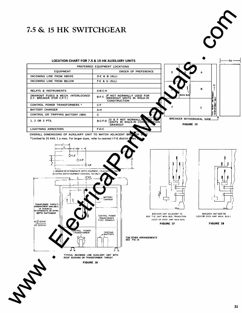
7.5 & 15 HK SWITCHGEAR
LOCATION CHART FOR 7.5 & 15 HK AUXILIARY UNITS
PREFERRED EQUIPMENT LOCATIONS EQUI PMENT ORDER OF PREFERENCE D G A
I NCOMING LINE FROM ABOVE D·E & G (ALL) I NCOMING LINE FROM BELOW F·E & G (ALL) I H RELAYS & I NSTRUMENTS A·B·C·H E I I B I \ .. " DRAWOUT FUSES & MECH. I NTERLOCKED B·F·C t NOT NORMALLY USED FOR E.T. BREAKER (FOR C.P.T.) DRAWOUT UN ITS IN WALK·I N
CONSTRUCTION
MAIN BUS .. h ii ! - ..
CONTROL POWER TRANSFORMERS • C·F BATTERY CHARGER A·H
F c i i H :i l � 8 CONTROL OR TRIPPING BATTERY (48V) c 1, 2 OR 3 PTS. {D & F NOT NORMALLY USED FOR B·C·F·D U N ITS IN WALK- I N CONSTRUCTION
BREAKER WITHDRAWAL S I DE=.! DRAWOUT FIGURE 15
LIGHTNING ARRESTERS F·D·C
OVERALL DIMENSIONS OF AUXILIARY U N IT TO MATCH ADJACENT BREAKER UNIT * Limited to 25 kVA, 1 tfJ max. For larger sizes, refer to nearest I·T·E district sales office.
� MINIMUM OR INTERMEDIATE DEPTH EQUIPMENT, ( 15 HK 500,750 ONLY)
® EXTRA DEPTH EQUIPMENT ( 15HK500, 750 ONLY )
(
TRANSFORMER THROAT� ARRANGEMENT AVAILABLE
I N MINIMUM, INTERMEDIATE OR EXTRA
CEPTH SWITCHGEAR.
120� ( 1200Al
123.
(2000 A )
" .j. _,r:-90!:,.
i i i +--t-r+ I! V;u,
1 ! i11 o-�TT ERY
CHARGER ul ! ul L_J._j _ _ _ _ _ _ t-
-I CONTROL POWER
TRANSFORM E R F U S E DRAWOU T
CONTROL POWER T RANSFORMER TRIPPING
� I rill"" n n
TYPICAL INCOMING LINE AUXILIARY UNIT WITH ROOF BUSHING OR TRANSFORMER THROAT
FIGURE 16
I
BREAKER UNIT ADJACENT TO
BUS T I E U N I T WITH BUS TRAN S ITION
( 1 2 0 0 OR 2000 AMP. MAIN BUS) FIGURE 17
F OR OTHER ARRANGEMENTS EE FIG. 15 s
BREAKER UNIT BUS TIE ( 1 200 OR 2000 A M P. MAI N BUS )
FIGURE 18
31 www . El
ectric
alPar
tMan
uals
. com
www . El
ectric
alPar
tMan
uals
. com
32
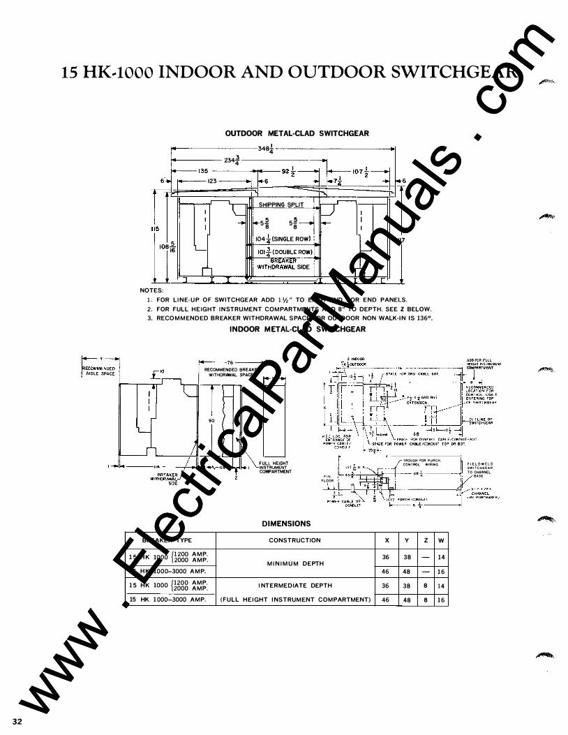
15 HK .. lOOO INDOOR AND OUTDOOR SWITCHGEAR
r-M:::�
OUTDOOR METAL·CLAD SWITCHGEAR
234� - 135
• 1 ..
n 1i I
5 8i6
NOTES:
123
lc I I ..... I
L--
r'l
3484
.. 1·�6 92!-=1 •7* - 1o 1 t:j I -:-, I
II SHIPPING SPLIT I : r5
2 5L-1 8 8
: 104*- (SINGLE ROW) :
IOI! (DOUBLE ROWJ \. : WITH���w�r SlOE i
=r- I - I
I
I--'
r1
•6 1 117
1 . FOR LI NE· U P OF SWITCHGEAR ADD 1 V2 " TO EACH END FOR END PANELS. 2. FOR FULL HEIGHT I N STRUMENT COMPARTMENTS ADD 8" TO DEPTH. SEE Z BELOW. 3. RECO M M ENDED BREAKER WITHDRAWAL SPACE FOR OUTDOOR NON WALK·I N IS 136".
INDOOR METAL-CLAD SWITCHGEAR
14---7s •I RECOMMENDED BREAKER
WITHDRAWAL SPACE r��� SPACE 1 n----...--Trl roe-·�
l _j-1 .. -
BREAKER TYPE
1 5 H K
15 H K
1 5 HK
1000 p2oo A M P. 2000 AMP.
1000-3000 A M P.
1000 p2oo AMP. 2000 AMP.
15 HK 1000-3000 AMP. (FULL
TROUGH FOR PURCH. CONTROL WIRING FULL HEIGHT INSTRUMENT COMPARTMENT F I N . 1o FLOOR •' -T::r=�st:;;;;-+--- 68 � -----''
_Lj
DIMENSIONS
CONSTRUCTION X y z w
36 38 - 14 M I N I M U M DEPTH
46 48 - 16
I NTERMEDIATE DEPTH 36 38 8 14
HEIGHT I NSTRUMENT COMPARTMENT) 46 48 8 16
F I E L D W E L D SWITCHGEAR TO CHANNEL BASE
www . El
ectric
alPar
tMan
uals
. com
www . El
ectric
alPar
tMan
uals
. com
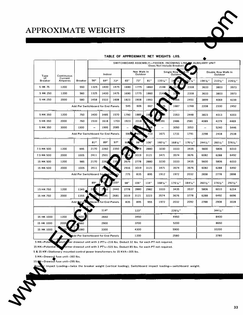
APPROXIMATE WEIGHTS
TABLE OF APPROXIMATE NET WEIGHTS -LBS.
SWITCHBOARD ASSE M B LY-FEEDER. I NCOM I N G L I N E O R AUXI LIARY UNIT (Does Not I nclude B reaker)
Non Walk- In Single Row Walk- I n Type Continuous Indoor Outdoor Outdoor
of Cu rrent Breaker Amperes Breaker 5611 6411 7211 65" 73" 81" 135 '!. " 143 1/4 "
5 HK 75 1 200 550 1 325 1400 1475 1 690 1 775 1860 2148 2233
5 HK 250 1 200 560 1325 1400 1475 1690 1775 1860 2148 2233
5 HK 250 2000 580 1458 1533 1 608 1823 1908 1993 2281 2366
Add Per Switchboard for End Panels 545 606 667 1626 1 687
5 H K 350 1 200 750 1400 1485 1 570 1 790 1885 1980 2258 2353
5 HK 350 2000 760 1 533 1618 1703 1923 2018 2 1 1 3 2391 2486
5 HK 350 3000 1300 - 1995 2085 - 2495 2598 - 3050
Add Per Switchboard for End Panels 590 650 7 1 0 1671 1731
8111 8911 9711 90" 98" 106" 1 60 1/4" 1681/4 "
7 .5 HK 500 1 200 995 2 1 70 2260 2350 2675 2778 2880 3230 3333
7.5 HK 500 2000 1005 241 1 2501 2591 2916 3019 3121 3471 3574
15 HK 500 1 200 985 2 1 70 2260 2350 2675 2778 2880 3230 3333
15 HK 500 2000 1005 241 1 2501 2591 2916 3019 3121 3471 3574
Add Per Switchboard for End Panels 775 835 895 1912 1972
8911 9711 10511 98" 106" 1 14" 168 1/4" 1 76 1/4 "
1 5 H K 750 1 200 1 345 2260 2350 2440 2778 2880 2982 3333 3435
15 HK 750 2000 1355 2501 2591 2681 3019 3121 3223 3574 3676
Add Per Switchboard for End Panels 835 895 955 1 972 2032
1 1 411 123" 2261/4"
15 HK 1000 1 200 2600 2650 3450 4950
15 HK 1000 2000 2660 2900 3700 5200
15 HK 1000 3000 3380 3300 4300 5900
Add Per Switchboard for End Panels 1 200 2580
5 H K-Potential transformer d rawout unit with 3 PT's-2 1 6 lbs. Deduct 32 lbs. for each PT not required.
15 H K-Potential transformer d rawout un it with 3 PT's-515 lbs. Deduct 85 lbs. for each PT not required.
5 & 15 KV-Stationary mounted control power transformers to 15 KVA-305 lbs.
5 H K-Drawout fuse un it-160 lbs.
1 5 H K-Drawout fuse un it-295 lbs.
1 51 1!. "
2318
2318
2451
1 748
2448
2581
3153
1791
1 76 '!. "
3435
3676
3435
3676
2032
1841!. "
3537
3778
2092
Breaker I m pact Loading-twice the breaker weight (vertical loading); Switchboard impact loading- switchboard weight.
Double Row Walk· l n Outdoor
1 94 1h " 210 1/2 " 2261h "
3633 3803 3973
3633 3803 3973
3899 4069 4239
2208 2330 2452
3823 4013 4203
4089 4279 4469
- 5240 5446
2298 2418 2538
244 1/2 " 260 '/2 " 276 1/2 "
5600 5806 6010
6082 6288 6492
5600 5806 6010
6082 6288 6492
2658 2778 2898
260 1h " 2761h " 292 1h "
5806 6010 6214
6288 6492 6696
2788 2908 3028
344 1/2 "
8400
8650
10200
3780
33 www . El
ectric
alPar
tMan
uals
. com
www . El
ectric
alPar
tMan
uals
. com
34
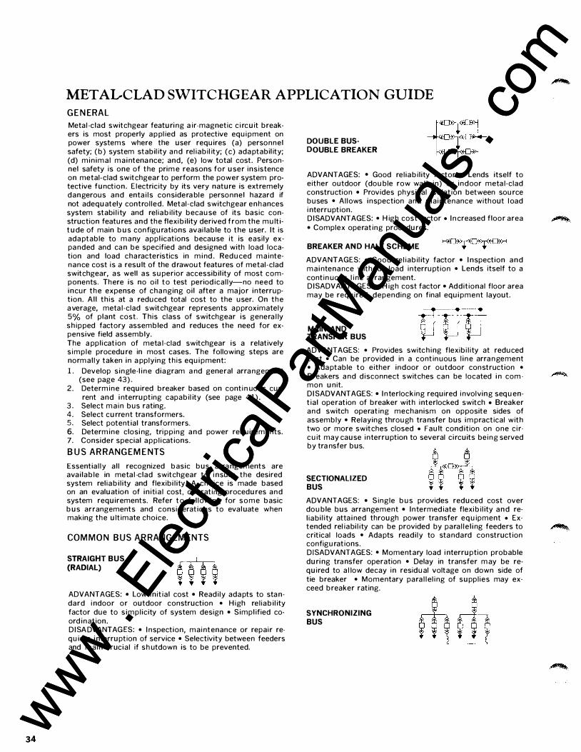
METALCLAD SWITCHGEAR APPLICATION GUIDE
GENERAL
Metal -c lad switchgear featuri ng a ir-magnetic c i rcuit breakers is most properly a p pl ied as protective equi pment on power systems where the user requires (a) personnel safety; (b) system stabil ity and rel iabi l ity; (c) ada ptabil ity; (d) min ima l mai ntena nce; and, (e) low total cost. Personnel safety is one of the prim e reasons for user ins istence on metal-clad switchgear to perform the power system protective function. E lectricity by its very nature is extremely dangerous and enta i ls considera ble personnel hazard if not adequately control led. Metal-clad switchgear enhances system stabi l i ty and rel iabi l i ty because of its basic construction features and the flexibi l ity derived from the multitude of main bus configurations avai lable to the user. It is ada ptable to many appl ications because i t is easi ly expa nded and ca n be specified and designed with load location and load characteristics in m i nd . Reduced m a intenance cost is a result of the drawout features of metal-clad switchgear, as well as superior accessibil ity of most components. There is no oi l to test period ical ly-no need to incur the expense of cha nging oi l after a major interruption. A l l th is at a reduced total cost to the user. On the a verage, meta l -clad switchgear represents a pproximately 5% of plant cost_ This class of switchgear is genera l ly sh ipped factory assembled and reduces the need for expensive field assembly. The a ppl ication of meta l -clad switchgear is a relatively s imple procedure in most cases. The following steps are normal ly taken in a pplying th is equi pment:
L Develop s ingle-l i n e diagram a nd general arra ngement (see page 43) .
2. Determ ine required breaker based on conti n uous cur-rent and i nterrupting capabil ity (see page 4 1 ) .
3 . Select ma in bus rating_ 4. Select current tra nsformers. 5. Select potential transformers. 6. Determ ine closi ng, tri pp ing a n d power requirements. 7. Consider special app l ications.
BUS ARRANGEMENTS
Essentia l ly a l l recognized basic bus arra ngements are ava i lable in meta l -clad switchgear to i nsure the desired system rel iabi l i ty and flexibi l i ty_ A choice is made based on an evaluation of in i ti a l cost, operating procedures and system requirements_ Refer to fol lowi ng for some basic bus arrangements and considerations to evaluate when making the ultimate choice.
COMMON BUS ARRANGEM ENTS
STRAIGHT BUS (RADIAL)
ADVANTAGES: • Low i n it ia l cost • Read i ly ada pts to sta ndard i ndoor or outdoor construction • H igh rel iabi l ity factor due to s impl icity of system design • Simpl ified coord ination. D I SA DVANTAG ES: • I nspection, mai ntenance or repair requires i nterruption of service • Selectivity between feeders and main crucia l if shutdown is to be prevented.
DOUBLE BUSDOUBLE BREAKER
ADVANTAGES: • Good rel iabi l ity factor • Lends itself to either outdoor (double row wa l k- in) or indoor meta l -clad construction • Provides physical isolation between source buses • Al lows inspection and mai ntenance without l oad i nterruption. D I SADVANTAGES: • H igh cost factor • I n creased floor area • Complex operating procedures.
BREAKER AN D HALF SCHEME
ADVANTAGES: • Good rel iabi l ity factor • I nspection a n d mai ntena nce without load interruption • Lends itself to a cont inuous l i ne arrangement. D I SADVANTAGES: • H igh cost factor • Additional floor area may be required, depending on final equi pment layout.
MAIN AND TRANSFER BUS
ADVANTAGES: • Provides switch ing flexibi l i ty at reduced cost • Can be provided in a continuous l i ne arra ngement • Ada ptable to e ither indoor or outdoor construction • Breakers a nd d isconnect switches can be located i n com mon unit. D I SADVANTAGES: • I n terlocking required i nvolving sequent ial operation of breaker with interlocked switch • Breaker and switch operating mechanism on opposite sides of assembly • Relaying through tra nsfer bus im practical with two or more switches closed • Fault cond ition on one c ircuit may cause interruption to several circuits being served by tra nsfer bus_
SECTIONALIZED BUS
ADVANTAGES: • Single bus provides reduced cost over double bus arrangement • I n termed iate flexibi l ity a n d rel iabi l i ty atta i ned through power tra nsfer equipment • Extended rel iabi l i ty can be provided by para l le l i ng feeders to critical loads • Ada pts readi ly to sta ndard construction configurations_ DISADVANTAGES: • Momentary load i nterruption probable duri ng tra nsfer operation • Delay in transfer m ay be required to a l low decay in residual voltage on down side of tie breaker • Momentary para l l el i ng of suppl ies may exceed breaker rating_
SYNCHRONIZING BUS
www . El
ectric
alPar
tMan
uals
. com
www . El
ectric
alPar
tMan
uals
. com
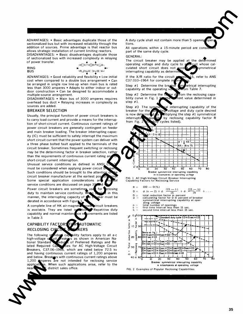
ADVANTAGES: • Basic adva ntages d u pl icate those of the sectional ized bus but with increased re l iab i l ity through the addition of sou rces. Prime adva ntage is that reactor bus a l lows strategic instal lation of cu rrent l i m it ing reactors. D ISADVANTAGES: • Basic d isadvantages d u pl icate those of sect ional ized bus with increased complexity in rel aying of power tra nsfer.
R I N G BUS
ADVANTAG ES: • Good rel iab i l ity and flexib i l ity • Low in it ial cost when compa red to a double bus a rra ngement • Ca n be a rranged in s ingle row l i ne-up when main bus is rated less than 3000 amperes • Ada pts to either i ndoor or outdoor construction • Can be designed to accom modate a m ulti ple-source arra ngement. D I SADVANTAGES: • Main bus of 3000 am peres req u i res overhead bus du ct • Relaying increases i n complexity as sources a re added .
BREAKER SELECTION
Usua lly, the pr incipal fu nction of power c i rcuit breakers is
to carry load cu rrent and provide a means for the i nterruption of short-c i rcuit cu rrent. Cont inuous cu rrent ratings of
power c i rcuit breakers a re genera l ly cont ingent on feeder
and main breaker load i ng. The b reaker interrupting capac
ity ( IC) m ust be suffic ient to safely i nterrupt the max i m u m short c i rc u it cu rrent that t h e power system can del iver with
a three phase bolted fa ult a ppl ied to the termina ls of the
c i rc u it breaker. Sometimes freq u ent switch ing or reclosing may be the determ i n i ng factor in breaker selection, rather
than the req u i rements of conti nuous c u rrent rating and/or
short-c i rcuit c u rrent i nterruption.
U n usual service condit ions as d efined in ANSI C37.04
must be considered when a pplying power c i rc u it brea kers .
Such conditions should be brought to the attention of the
c i rcuit brea ker man ufacturer at the ea rl iest possib le t ime.
Some specia l appl ication considerations and u n usual
service conditions are discussed on page 39 and 40.
Power c i rcuit breakers are sometimes used for reclosing
duty to mainta in service conti nu ity. When appl ied in this
man ner, the interru pting capacity of the b reaker m ust be
derated in accordance with Figu re 1 .
A com plete l i n e of H K a i r-magnetic power c i rc u it b reakers is available. They are listed in Ta b l e 7. Repetitive d uty capabi l ity and normal maintenance requ i rements are l i sted
in Table 3.
CAPABILITY FACTORS FOR AUTOMATIC
RECLOSING CIRCUI T BREAKERS
The following standard capabi l ity factors a pply to a l l a-c h igh-voltage c i rcu it breakers as shown i n America n Nationa l Sta ndard Sched u les of Preferred Rati ngs and Related Req u i red Ca pabi l it ies for AC H igh-Voltage C i rcuit Breakers, C37.06-1966, which are rated below 72.5 kv and having conti nuous cu rrent ratings of 1 , 200 a m peres and below. Breakers with cont inuous c u rrent ratings a bove 1 , 200 a m peres a re not i ntended for reclosing service appl ications. When such appl ications a rise, refer to the nea rest I ·T·E d istrict sales office.
A d uty cycle sha l l not conta in more than 5 opening opera· t ions.
A l l operations with in a 1 5- m i n ute period a re considered part of the same d uty cycle.
G E N ERAL:
The c i rcu i t breaker may be a pp l ied at the determ ined operating voltage and d uty cyc l e to a c i rcuit whose ca l · c u lated short c i rcu it does not exceed the symmetrical i nterrupt ing capabi l ity as determi ned.
If the X/R ratio for the c i rcu it exceeds 1 5, refer to ANS C37 .010-1 964 for com plete i nformation.
Step # 1 Determ ine the b reaker sym metrical interru pting capabi l ity at the operati ng voltage from Ta
.ble 7.
Step #2 Determ ine the factor d, from the reclosing capa· b i l ity c u rve in Fig. 1 for the cu rrent va l u e determined in step # 1 .
Step #3 T h e sym metrical i nterrupting capabi l ity of the b reaker for the operating voltage and d uty cyc le des i red is now dete rmi ned by m u lt ip ly ing the step #1 symmetrical i nterru pt i ng capabi l ity by reclosi ng capabi l ity factor R from Fig. 2 (for duty cycles l i sted).
0 ,g 0 c �
� r- L � i-�;�, O to l8 -,g 5 c ·� I'. d ' t KA .......
...... KA ' 18 to 75 � I *
" ...... .....
10 20 30 40 50 60 70 80 Breaker sym metrical interrupting capability
in k i l o a m peres at operating vo ltage
FIG. 1 AC H igh-Voltage Circuit Breaker I nterrupting Capabil ity Factors for Reclosing Service
R = 100 - D( % ) (15 - t. ) (15 - t2)
D = d1 (n - 2) + d , 15 + d , 15 + · · ·
,g 0 c 0 t;
D = total reduction factor in percent d, = calculating factor for D in percent of breaker
symmetrical interrupting capabil ity at oper· ating voltage
n = total n umber of openings t 1 = first t ime interval less than 15 sec. t2 -= second t ime interval less than 15 sec.
0 �100 .s -- - '!'-S�ndord duty cycle CO+I5 sec+CO
0 - · ---- ... r-- - ----- - - .... ... -.oil -,g 1 0 � 90 ... ... --... �"-...::: - · -c >-0 7; .0 � 20 g_ 80 � s 2 go
Some OS fi� I ' 0+ 15 sec+ 0+15sec+ Co-r---:
-o+? sel+c
1o J. I .i ..
f2+15sec+CO+I5sec+CO+I5sec+CO ' Ot9sec + CO + 1
15sec+CO I I
- .. .. :/' -. - -
'' ... � 30 � 70 u " "
0+ 15sec+CO+ 15sec+C0+15sec+C.£.+15sec+ CO O+Osec+CO+ 15sec+CO+I5sec+CO (-- . · ... a: 0 " O+?si+C?+ t1
5se/+Cf+fj+C�
40 a: 600 10 20 30 40 50 60 Breaker symmetrical interrupting capability
in kiloamperes at operating voltage FIG. 2 Examples of Popu lar Reclosing Capabi l ities
· , 70 80
35
www . El
ectric
alPar
tMan
uals
. com
www . El
ectric
alPar
tMan
uals
. com
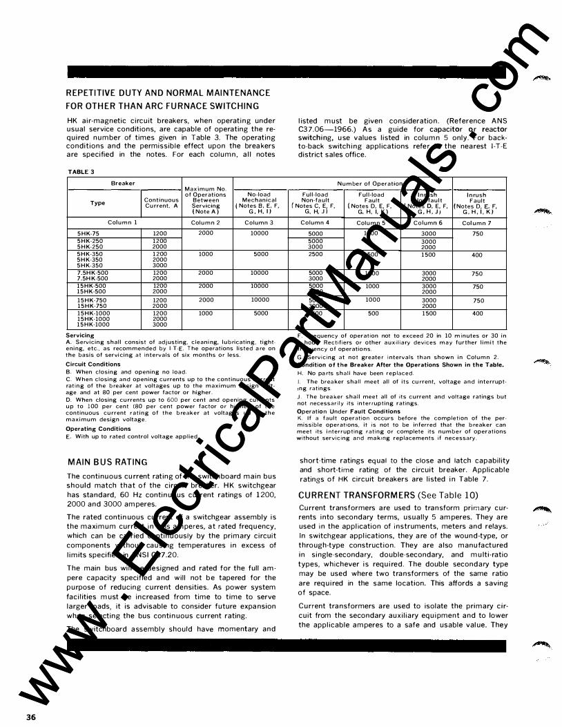
36
REPETITIVE DUTY AND NORMAL MAINTENANCE
FOR OTHER THAN ARC FURNACE SWITCHING
HK a i r-magnetic c i rc u it breakers, when operat i ng under usual service conditions, are capable of operating the req u i red n u m ber of times given in Table 3. The operat ing condit ions a nd the permiss ib le effect upon the brea kers a re specified in the notes. For each col u m n , a l l notes
TABLE 3
Breaker Maximum No. of Operations No-load
Type Continuous Between Mechanical Cu rrent. A Servicing ( Notes 8 , E, F,
( Note A ) G , H, l )
Column 1 Colu m n 2 Column 3
5HK-75 1200 2000 10000 5HK-250 1200 5HK-250 2000 5HK-350 1 200 1000 5000 5H K-350 2000 5HK-350 3000 7.5H K-500 1200 2000 10000 7.5H K-500 2000 15HK-500 1200 2000 10000 15HK-500 2000
15HK-750 1200 2000 10000 15HK-750 2000 15HK-1000 1200 1000 5000 15HK-1000 2000 15HK-1000 3000
Servicing A. Servicing sha l l consist of adj usting, c leani ng, l ub ricating, tightening, etc., as recommended by 1-T-E. The operations l isted a re on the basis of servicing at intervals of six months o r less.
Circuit Conditions B. When closing and opening no load. C. When closing and opening cu rrents up to the continuous current rat ing of the b reaker at voltages up to the maximum design voltage and at 80 per cent power factor or higher. D. When closing cu rrents up to 600 per cent and opening cu rrents up to 100 per cent (80 per cent power factor o r higher) of the continuous cu rrent rat ing of the b reaker at voltages up to the max imum design voltage_
Operating Conditions E. With up to rated control voltage appl ied.
MAIN BUS RATING
The conti nuous cu rrent rat ing of the switch board ma in bus shou ld match that of the c irc u it breaker. H K switchgear
has sta ndard, 60 Hz conti n uous c u rrent ratings of 1 200, 2000 and 3000 am peres.
The rated conti n uous cu rrent of a switchgear assembly i s the maxi m u m current i n rms a m peres, a t rated freq u ency,
which can be carried conti n u ously by the primary c i rcuit
components without ca u s i ng tem peratu res i n excess of
l i m its specified in ANSI C37.20.
The main bus wi l l be designed a nd rated for the ful l a m
pere ca pacity specified a nd wi l l not b e tapered for the
p u rpose of red ucing c u rrent densities. As power system
fac i l ities m ust be increased from time to t ime to serve
larger loads, it is advisable to consider future expa nsion
when selecting the bus conti n uous c u rrent rating.
The switchboard a ssembly should have momentary and
l isted m ust be given consideration . (Reference A N S C3 7.06-1966.) A s a guide for capacitor o r reactor switchi ng, u se values l isted in col u m n 5 only. For backto-back switch i ng appl ications refe r to the nea rest 1 -T-E district sales office.
Number of Operations
Ful l- load Ful l- load I n rush I n rush Non-fa ult Fault Non-fau l t Fault ( Notes C, E
j F, ( Notes D. E, F, ( Notes D, E, F, ( Notes D, E. F,
G, H, J G, H, I, K ) G , H , J i G , H , I , K )
Column 4 Colu m n 5 Column 6 Col umn 7
5000 1000 3000 750 5000 3000 3000 2000 2500 500 1 500 400
5000 1000 3000 750 3000 2000 5000 1000 3000 750 3000 2000 5000 1000 3000 750 3000 2000 2500 500 1 500 400
F. Frequency of operation not to exceed 20 in 10 m inutes or 30 in 1 hou r. Rectif iers or other aux i l i a ry devices may further l im i t the freq uency of operations. G. Serv ic ing at not greate r i ntervals than shown in Column 2. Condition of the Breaker After the Operations Shown in the Table. H. No pa rts sha l l have been replaced. I . The brea ker shal l meet al l of its cu rrent, voltage and interrupttng ratings. J . The brea ker sha l l meet all of its current and voltage ratings but not necessar i ly its in terrupting ratings. Operat ion Under Fault Conditions K. I f a fault operation occurs before the completion of the permissible operations, it is not to be inferred that the b reaker can meet its i nterrupting rat ing or complete its number of operations without servic ing and ma kmg replacements if necessary.
short-time ratings eq ual to the close and latch capabi l ity and short-t ime rating of the c ircuit breaker. Appl icable
ratings of HK c ircu it breakers are l isted i n Table 7 .
CURRENT TRANSFORMERS (See Ta b le 1 0)
Cu rrent transformers a re used to tra n sform primary c u rrents i nto secondary terms, usua l ly 5 am peres. They a re used i n the appl ication of instruments, meters and relays.
In switchgear appl ications, they a re of the wound-type, or
through-type construct ion . They are a lso manufactured
in s i ngle-seconda ry, double-secondary, and m u lti -ratio
types, whichever i s req u i red. The double second a ry type
may be used where two tra nsformers of the same ratio
are req u i red in the same location. This affords a saving
of space.
Cu rrent tra nsformers a re used to isolate the primary c i r
c u it from the secondary aux i l iary eq u i pment a nd to lower
the appl icable a m peres to a safe and usable val ue. They
-�-
www . El
ectric
alPar
tMan
uals
. com
www . El
ectric
alPar
tMan
uals
. com
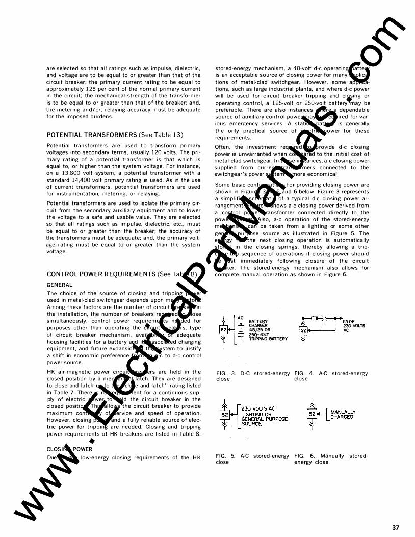
a re selected so that a l l ratings such as impu lse, d ie lectric,
and voltage a re to be eq ual to or greater than that of the c ircu it b reaker; the prima ry c u rrent rating to be eq u a l to
a pproximately 1 25 per cent of the normal p rimary cu rrent in the c i rcuit ; the mechan ical strength of the tra n sformer
is to be equal to or greater than that of the breaker; a nd,
the mete ring and/ or, relaying accu racy m ust be adeq uate
for the i m posed b u rdens.
POTENTIAL TRANSFORMERS (See Ta ble 1 3 )
Potential tra n sformers a re used t o transform pr imary voltages into secondary terms, usual ly 1 20 volts . The p ri
m a ry rating of a pote ntial tra nsformer is that which is equal to, or h igher than the system voltage. For instance,
on a 13,800 volt system, a pote ntial tra nsformer with a
sta ndard 14,400 volt pr imary rating is used. As in the use of cu rrent tra nsformers, potential transformers a re used for instrumentation, mete ri ng, or relaying.
Potential transformers a re used to isolate the pr imary c i r
c u it from the seconda ry a ux i l i a ry equ ipment and to lower the voltage to a safe and usable value. They a re sel ected
so that a l l ratings such as impu lse, d i electric, etc. , m ust
be eq ual to or greater than the b reaker; the accu racy of the transformers must be adeq uate; a nd, the pr imary volt
age rating must be equal to or greater than the system
voltage.
CONTROL POWER REQUIREMENTS (See Ta ble 8)
GEN ERAL
The choice of the source of closing and tripp ing power used in metal-clad switchgear depends u pon many factors.
Among these factors a re the n u mber of c i rc u it breakers in the insta l lation, the n u m be r of b rea kers req u i red to close
s im ultaneously, control power req u i rements needed for
pu rposes other than operating the c i rcuit breakers, type of c i rcu it b reaker mechan ism, ava i labi l ity of adeq uate
housing faci l ities for a battery and its associated charging eq u i pment, and futu re expansion of th e system to j u stify
a sh ift in econom ic p reference from an a-c to d-e control power source.
H K a i r-magnetic power c i rc u it breakers a re held i n the
closed position by a mechanical latch . They a re designed to close and latch up to the "close and latch" rating l isted
in Table 7. Th ere is no req u i rement for a conti nuou s s u pply of el ectric power to hold the c i rc u it b reaker in the closed posit ion. This a l lows the c i rcuit b rea ker to p rovide
maximum cont inu ity of service and speed of operation. However, clos ing power and a ful ly re l iable sou rce of elec
tric power for tripp ing a re needed. Closing and tripping
power req u i rements of HK brea kers a re l i sted i n Ta ble 8.
CLOS I NG POWER
Due to the low-energy closing req u i rements of the H K
stored -energy mechanism, a 48-volt d-e operating battery is an accepta ble source of closing power for many a ppl ica
t ions of metal-clad switchgear. However, some appl ica
tions, such as large ind ustrial pla nts, and where d-e power
wi l l be used for c i rcu it b reaker tripp ing and closing or
operati ng control, a 1 25-volt or 250-volt battery may be p referable. There a re a lso i n stances where a dependa ble
source of aux i l i a ry control power may be req u i red for var
ious emergency services. A station battery is generally
the only p ractical sou rce of electric power for these
req u i rem ents.
Often , the i nvestment requ i red to p rovide d-e closing power is u nwa rranted when com pa red to the i n it ial cost of metal-clad switchgear. I n these instances, a -c closi ng power
su ppl ied from cu rrent tra n sformers connected to the switchgea r's power system is more econom ica l .
Some basic configu rations f o r provid ing closing power a re
shown in Figu res 3, 4, 5 and 6 below. Figu re 3 represents
a s impl ified schematic of a typical d-e closing power a r
ra ngem ent. F igure 4 shows a-c closing power derived from
a control power tra n sformer con nected d i rectly to the
power system. Also, a-c operation of the stored -energy
mechanism can be taken from a l ighting or some other
general pu rpose sou rce as i l l u strated i n Figu re 5. The
energy for the next clos ing operat ion is automatica l ly stored i n the closing spr ings, thereby a l lowi ng a trip
close-trip seq u ence of operations if closi ng power should be lost immediately following c losure of the c i rcuit
b reaker. The stored -ene rgy mechanism a lso a l lows for complete manual operation as shown in Figure 6.
AC
± T
BATTERY CHARGER 48,125 OR 250-VOLT TRIPPING BATTERY
rE J'••oo 230 VOLTS AC
I
FIG. 3. D-C stored-energy FIG. 4. A-C stored-energy close close
h. �MANUALLY T- LCHARGED y
FIG. 5. A-C stored -energy FIG. 6. Manual ly stored-close energy close
37
www . El
ectric
alPar
tMan
uals
. com
www . El
ectric
alPar
tMan
uals
. com
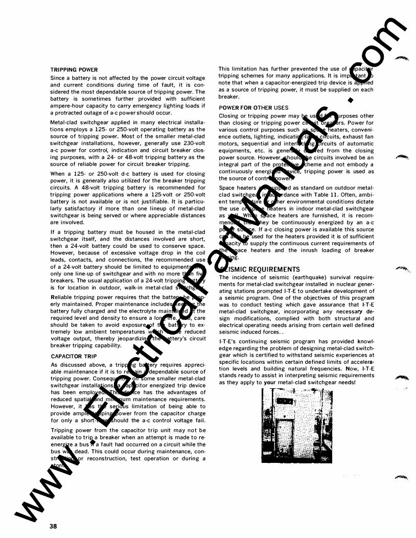
TRI PPING POWER
Si nce a battery is not affected by the power circuit voltage and cu rrent conditions d u ring time of fault, it is con
sidered the most dependable sou rce of tripping power. The
battery is sometimes further provided with sufficient
a m pere-hour capacity to ca rry emergency l ighting loads if
a protracted outage of a-c power should occur.
Meta l-clad switchgear a pplied in many electrical i nstal la
t ions employs a 1 25- or 250-volt operating battery as the
sou rce of tri pping power. Most of the smal ler meta l -clad switchgear i nsta l lations, however, generally use 230-volt
a-c power for control, indication and circuit breaker clos
i ng pu rposes, with a 24- or 48-volt tripping battery as the source of rel iable power for circuit breaker tri pping.
When a 1 25- or 250-volt d-e battery is used for closing power, it is genera l ly a lso uti l ized for the breaker tripping
c ircu its. A 48-volt tripping battery is recommended for
tripping power appl ications where a 1 25-volt or 250-volt
battery is not ava i lable or is not justifiable. It is particu
larly satisfactory if more tha n one l i neup of metal-clad switchgear is being served or where a ppreciable distances a re i nvolved.
If a trippi ng battery m ust be housed in the meta l-clad switchgear itself, and the distances i nvolved a re short,
then a 24-volt battery could be used to conserve space. However, because of excessive voltage d rop in the coil
leads, contacts, a nd connections, the recom mended use
of a 24-volt battery should be l im ited to equi pments with only one l i ne-up of switchgear and with no more than five breakers. The usual appl ication of a 24-volt tripping battery
is for location in outdoor, walk-in metal-clad switchgear.
Reliable tripping power req u ires that the battery be properly mai nta ined. Proper mai ntenance incl udes keeping the
battery ful ly charged and the electrolyte mai ntained at the requ i red level and density to ensure a long l ife_ Also, care
should be taken to avoid exposure of the battery to extremely low am bient temperatures which cause red uced voltage output, thereby jeopardizing the battery's circuit breaker tripping ca pabi l ity.
CAPACITOR TRI P
As discussed above, a tripping battery req u i res appreciable mai ntenance if it is to remain a dependable sou rce of tripping power. Consequently, on some smaller metal -clad switchgear i nstal lations, a capacitor energized trip device has been employed. This device has the adva ntages of
reduced spatial and min imum maintenance requ i rements.
However, it has the serious l im itation of being able to
provide ample tripping power from the capacitor charge
for only a short-time should the a -c control voltage fa i l .
Tripping power from the capacitor tr ip unit may not be
avai lable to tr ip a breaker when a n attempt is made to re
energize a bus if a fault had occu rred on a c ircuit while the
bus was dead. This could occur during maintenance, construction or reconstruction, test operation or d u ring a
storm.
38
Th is l imitation has further prevented the use of capacitor tripping schemes for many a ppl ications. It is im portant to
note that when a capacitor-energized tri p device is appl ied
as a source of tripping power, it m ust be suppl ied on each
breaker.
POWER FOR OTHER USES
Closing or tripping power may be used for purposes other than closing or tripping power circuit breakers. Power for
various control purposes such as space heaters, convenience outlets, l ighti ng, indicating-lamp c ircu its, exhaust fa n motors, seq uential and interlocking c ircuits of a utomatic
equi pments, etc. is genera l ly derived from the closing
power source_ However, should the c ircu its involved be a n integral pa rt of the protective scheme a n d not embody a cont in uously energized device, tripping power is used as
the source of control power.
Space heaters are suppl ied as standard on outdoor meta l
c lad switchgear in accordance with Table 1 1 . Often, ambi ent temperature or other environmental cond itions- dictate
the use of space heaters in i ndoor metal-clad switchgear as wel l . When space heaters a re furnished, it is recom
mended that they be conti nuously energized by an a-c
power source. If a-c closing power is ava i lable this sou rce
ca n also be used for the heaters provided it is of sufficient capacity to supply the conti n uous current req u irements of the space heaters and the i n rush loading of breaker
closing_
SEISMIC REQUIREMENTS The i ncidence of seismic (ea rthquake) survival req u i rements for metal-clad switchgear i nstal led in n uclear generating stations prom pted 1 -T-E to u ndertake development of a seismic program. One of the objectives of this program was to cond uct testing which gave assurance that 1-T-E meta l-clad switchgear, incorporating a ny necessary de
sign modifications, compl ied with both structural and electrical operating needs arising from certai n wel l defined seismic i nduced forces. _
1-T-E's continu ing seismic program has provided knowledge regarding the problem of designing metal-clad switchgear which is certified to withstand seismic experiences at specific locations within certai n defined l im its of acceleration levels and bui lding natura l freq uencies. Now, 1-T-E stands ready to assist in i nterpreting seismic requ i rements
as they a pply to your meta l -clad switchgear needs!
www . El
ectric
alPar
tMan
uals
. com
www . El
ectric
alPar
tMan
uals
. com
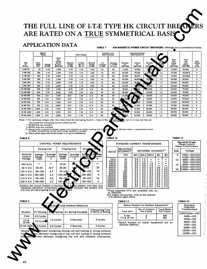
THE FULL LINE OF I .. T .. E TYPE HK CIRCUIT BREAKERS
ARE RATED ON A TRUE SYMMETRICAL BASIS
APPLICATION DATA TABLE 7 AIR-MAGNETIC POWER CIRCUIT BREAKERS--Ratings on a symmetrical basis.
Nominal Insulation level Interrupting Ratingst Rating Rated Voltages Rated Withstand AMPS-Symmetrical
Rated Con-
tinuotts Asym-Type Three- Current Maximum K-Factor Minimum LOW lmpu\se.6, Maximum Nominal Minimum metricato of Phase ���w�� 60 Hertz Voltage Max. KV Voltage Frequency 1.2 ,x50MS KV KV KV Breaker MVA AMPS-RMS KV-RMS Min. KV KV-RMS KV-RMS KV-Crest AMPS-RMS AMPS-RMS AMPS-RMS
5 HK 75 75 4.16 1,200 4.76 1.36 3.50 19. 60. 9,100 10,500 12,500
5 HK 250 250 4.16 1,200 4.76 1.24 3.85 19. 60. 30,300 35,000 37,500
5 HK 250 250 4.16 2,000 4.76 1.24 3.85 19. 60. 30,300 35,000 37,500
5 HK 350 350 4.16 1,200 4.76 1.19 4.00 19. 60. 42,400 48,600 50,000
5 HK 350 350 4.16 2.000 4.76 1.19 4.00 19. 60. 42,400 48,600 50,000
5 HK 350 350 4.16 3,000 4.76 1.19 4.00 19. 60. 42,400 48,600 50,000
7.5 HK 500 500 7.20 1,200 8.25 1.25 6.6 36. 95. 35,000 40,000 44,000
7.5 HK 500 500 7.20 2,000 8.25 1.25 6.6 36. 95. 35,000 40,000 44,000
15 HK 500 500 13.8 1,200 15.0 1.30 11.5 36. 95. 19,300 21,000 25,000
1 5 HK 500 500 13.8 2,000 15.0 1.30 11.5 36. 95. 19,300 21,000 25,000
15 HK 750 750 13.8 1.200 15.0 1.30 1 1.5 36. 95. 28,900 31 ,500 37,500
15 HK 750 750 13.8 2,000 15.0 1.30 1 1 . 5 36. 95. 28,900 31 ,500 37,500
15 H K 1000 1,000 13.8 1,200 15.0 1.30 1 1 .5 36. 95. 38,500 42,000 50,000
15 HK 1000 1,000 13.8 2,000 15.0 1.30 1 1 .5 36. 95. 38,500 42,000 50,000
15 HK 1000 1 ,000 13.8 3,000 15.0 1.30 11.5 36. 95. 38,500 42,000 50,000
Notes: t-For operating voltages other than those listed the interrupting Current = Amps at Max. KV Op�r:�i
nKgV
KV but in no case can this cur-
rent exceed the Interrupting Current at Minimum KV. • -60,000 Amp also available. i-80,000 Amp also available.
0- Rating factor is based on breaker speed from initiation to contact parting with 1/2 cycle relay time. M u ltiply factor X symmetrical current to obtain asymmetrical current interrupting capability of breaker .
.6,-These values apply with circuit breaker in or out of switchboard.
TABLE B TABLE 10
Rating Factor 1.2
1.2
1.2
1.2
1 .2
1.2
1.2
1.2
1.2
1.2
1.2
1.2
1 . 2
1 . 2
1.2
CONTROL POWER REQUIREMENTS STANDARD CURRENT TRANSFOR MERS
Closing Coil Tripping Coil Charging Motor . RELAY I NGt METERING ACCURACY t RATIO ACCURACY Nominal Voltage Average Voltage Average Voltage Average Control Range, Current, Range, Current, Range, Current Voltage Volts A Volts A Volts A
24V D-CA. - - 14-30 22.0 - -
48 V D-C 35-50 10.7 28-60 10.7 35·50 20 1 2 5 V D·C 90-130 6.7 70-140 6.7 90-130 10 250 V D-C 180-260 2.2 140-280 2.2 1 80-260 5 1 1 5 V A·C 95-125 4.5 95-125 4.5 95-125 10 230 V A·C 1 90-250 2.3 1 90-250 2.3 190-250 5
A-Unless the circuit breaker is located close to the battery and relay and adequate electrical connections are provided between the battery and trip coil, 24-volt tripping is not recommended.
TABLE 9
HK BREAKER T I M E CHARACTERISTICS
10H B0.1 B0.2 80.5 81 75/5 10 0.6 1 .2 - -
100/5 10 0.6 1.2 - -1 50/5 20 0.3 0.6 1 .2 -200/5 20 0.3 0.6 1 .2 -300/5 50 0.3 0.3 0.3 0.6 400/5 50 0.3 0.3 0.3 0.3 600/5 100 0.3 0.3 0.3 0.3 800/5 100 0.3 0.3 0.3 0.3
1 200/5 200 0.3 0.3 0.3 0.3 1 500/5 200 0.3 0.3 0.3 0.3 2000/5 200 0.3 0.3 0.3 0.3 2500/5 200 0.3 0.3 0.3 0.3 3000/5 200 0.3 0.3 0.3 0.3 4000/5 200 0.3 0.3 0.3 0.3
• Front mounted CT's are available only u p to 2000/5A.
tFor higher accuracies, refer to the nearest 1-T-E district sales office.
TABLE 1 1
82 ----
1 .2 0.6 0.3 0.3 0.3 0.3 0.3 0.3 0.3 0.3
Space Heaters for Outdoor Equipment•
Short Close Time and Inter-
Rating Latch rupting 3 Sec. Rating Time AMPS-RMS AMPS·RMS Cycles
1 2,500 20,000 5
37,500 60,000 :j: 5
37,500 60,000:j: 5
50,000 80,000 5
50,000 80,000 5
50.000 80,000 5
44,000 70,000 5
44,000 70,600 5
25,000 40,000' 5
25,000 40,000" 5
37,500 60,000t 5
37,500 60,000t 5
50,000 80,000 5
50,000 80,000 5
50,000 80,000 5
TABLE 12 Standard Single
Phase Control Power Transformers
KVA Voltage 5 2400-240/120
4160-240/120 1 0 4800-240/120
7200-240/120 1 5 8400-240/120
13200-240/120 25 13800-240/120
TABLE 13
I nterrupting Time No. of Heaters Total Watts Standard Potential
Transformers Breaker Av. closing Av. Tripping Av. Spring Charging 0-100% of Rating
5 H K 4.5 Cycles 7.5 & 7.5 Cycles 1.5 Cycles 2 Seconds 5 Cycles 15 H K
1 5 H K 1000 6 Cycles 2.0 Cycles 2 Seconds 5 Cycles
Closing Time--Between energizing closing coil and making of arcing contacts. Tripping Time--Between energizing of trip coil and parting of arcing contacts. Interrupting Time--Between energizing trip coil and complete interruption.
41
Type Unit Per Frame Per Frame
5 H K 2 300 7.5 & 15 H K 3 450
•Space heaters on indoor equipment are an optional addition.
2400/4160y-120 2400-120 4200-120 4800-120 7200-120 8400-120
1200D-120 1440D-120
www . El
ectric
alPar
tMan
uals
. com
www . El
ectric
alPar
tMan
uals
. com
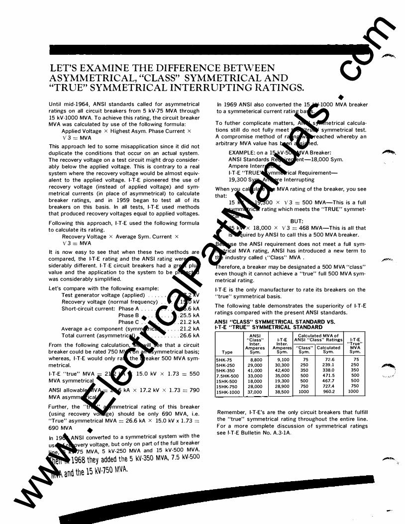
LET'S EXAMINE THE DIFFERENCE BETWEEN ASYMMETRICAL, "CLASS" SYMMETRICAL AND "TRUE" SYMMETRICAL INTERRUPTING RATINGS.
U ntil mid-1 964, ANSI standa rds called for asymmetrical ratings on all circuit breakers from 5 kV-75 MVA through
15 kV-1000 MVA. To achieve this rating, the circuit breaker MVA was calculated by use of the following form ula:
Applied Voltage x Highest Asym. Phase Current x V 3 = MVA
This approach led to some misappl ication since it did not dupl icate the conditions that occur on an actual system . The recovery voltage on a test circuit m ight drop considerably below the a ppl ied voltage. This is contrary to a real system where the recovery voltage would be almost equivalent to the a pplied voltage. 1-T-E pioneered the use of
recovery voltage (instead of a pplied voltage) and symmetrical cu rrents (in place of asymmetrical) to calculate breaker ratings, and in 1959 began to test all of its breakers on this basis. In all tests, 1-T-E used methods that produced recovery voltages equal to a ppl ied voltages.
Following this a pproach, 1 -T-E used the following form ula to calculate its rating.
Recovery Voltage x Average Sym . Cu rrent x V 3 = MVA
It is now easy to see that wh en these two methods are
compa red, the 1-T-E rating and the ANSI rat ing were considerably different. 1-T-E c i rcuit breakers had a great plus
value and the appl ication to the system to be protected was considerably simpl ified.
Let's compare with the following exa m ple: Test generator voltage (appl ied) . . . . . 1 7.2 kV
Recovery voltage (normal frequency) . . . . . . 1 5 .0 kV
Short-circuit current: Phase A . . . . . . . . . . . . 26.6 kA Phase B . . . . . . . . . . . . 25.5 kA Phase C . . . . . . . . . . . . 2 1 . 2 kA
Average a-c component (symmetrical) . . . . . 2 1 .2 kA Total cu rrent (asymmetrical) . . . . . . . . . . . . . 26.6 kA
From the following calculation, we will see that a circuit breaker could be rated 750 MVA on an asymmetrical basis; whereas, 1 -T-E would only rate the breaker 500 MVA sym
metrical.
1-T-E "true" MVA = 2 1 . 2 kA X 15 .0 kV X 1 . 73 = 550
MVA symmetrical
ANSI al lowable MVA = 26.6 kA X 1 7.2 kV X 1 . 73 = 790
MVA asymmetrical
Further, the "true" asymmetrical rating of this breaker
(using recovery voltage) should be only 690 MVA, i .e.
"True" asymmetrical MVA = 26.6 kA X 15.0 kV x 1 . 73 = 690 MVA
In 1 964 ANSI converted to a symmetrical system with the
use of recovery voltage, but only on part of the full breaker
l ine, 5 kV-75 MVA, 5 kV-250 MVA and 15 kV-500 MVA.
1hen in 1968 they added the 5 I<.V-350 MVA, 7 .5 kV-500
NN� and the 15 I<.'J-750 M'Jt-..
In 1969 ANSI also converted the 15 kV-1000 MVA breaker to a symmeterical cu rrent rating basis.
To futher compl icate m atters, ANSI symmetrical calcula
tions sti l l do not fully meet the "true" symmetrical test. A compromise method of rating was reached whereby a n
a rbitrary MVA value has been assigned.
EXAM PLE: on a 15 kV-500 MVA B reaker:
ANSI Standards Requ i rement-18,000 Sym. Ampere I nterrupting
1-T-E "TRU E" Symmetrical Requ i rement-
19,300 Sym. Ampere I nterrupting
When you calculate the MVA rating of the breaker, you see
that: 15 kV X 19,300 X V 3 = 500 MVA-This is a ful l symmetrical rating which meets the "TRUE" symmet
rical test BUT:
15 kV X 18,000 X V 3 = 468 MVA-This is al l that
is required by ANSI to cal l this a 500 MVA b reaker.
Because the ANS I req uirement does not meet a full symmetrical MVA rating, ANSI has introduced a new term to the industry called \ "Class" MVA .
Therefore, a breaker may be designated a 500 MVA "class" even though it can not ach ieve a "true" full 500 MVA symmetrical rating.
1-T-E is the only manufacturer to rate its breakers on the "true" symmetrical basis.
The following table demonstrates the superiority of 1-T-E ratings compa red with the present ANSI standards.
ANSI "CLASS" SYMMETRICAL STANDARD VS. 1-T-E "TRUE" SYMMETRICAL STANDARD
ANSI Calculated MVA of "Class" 1-T-E ANSI "Class" Ratings 1-T-E
Inter. Inter. "True" Amperes Amperes "Class" Calculated MVA
Type Sym. Sym. Sym. Sym. Sym.
5HK-75 8,800 9, 100 75 72.6 75 5HK-250 29,000 30,300 250 239.1 250 5HK-350 41,000 42,400 350 338.0 350 7.5HK-500 33,000 35,000 500 471.5 500 15HK-500 18,000 19,300 500 467.7 500 15HK-750 28,000 28,900 750 727.4 750 15HK-1000 37,000 38,500 1000 960.2 1000
Remember, 1-T-E's a re the only circuit breakers that fulfi l l
the "true" symmetrical rating throughout the enti re l ine.
For a more com plete discussion of symmetrical ratings
see 1-T-E Bul letin No. A.3-1A.
..... www . El
ectric
alPar
tMan
uals
. com
www . El
ectric
alPar
tMan
uals
. com
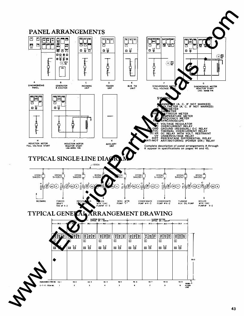
PANEL ARRANGEMENTS � (!] � � [� rrW!r'� .. JUL.J
A
SYKCHROHIZING PANEL
r-� ijJj!: �·•I liiori � � �t D C IDI C lll ini qp llll (;\IXC ,_; litH
D B
GENERATOR a EXCITER
gg� • • L.J c l(jJ c
c INCOMING
UNIT
�B LJ[;1LJ C ljjl
H
INDUCTION MOTOR FULL VOLT AGE START
� . . LJ O ljjl
t 6 f INOUCTION MOTOR
REACTOR START LINE-SIMES TYP1.
� '
gLJLJ
0 FEEDER
UNIT
K
AUXILIARY UNIT
�1f0C1fl)G� L�L . .JU LJ
1·· � l
E
BUS TIE UNIT
TYPICAL SINGLE-LINE DIAGRAM
Lj�LJ [Oi;,J:a�.-1 1�1 tl I L L....Jl.d � . . LJ w ... ....
c ljjl g�B F'it� � · .... c l(jJ
(;'� ,__litH.
� /- , r:xc. \ 0 . ,\.0 -../ ltM.
t 6 � I � t f F
SYNCHRONOUS MOTOR FULL VOLTAGE START
G
SYNCHRONOUS MOT'OR REACTOR START
UNI- lt:IUB TYII!
SYM BOLS
A v w VAR
WHM T
FM SYN
VR oc OC-GND
TOC OC·VR uv
DIFF ANTI-MOT
AMMETER (A. C. IF NOT MARKED) VOLTMETER (A. C. IF NOT MARKED) WATTMETER VARMETER WATTHO U R METER TEMPERATURE METER FREQUENCY METER SYNCHROSCOPE VOLTAGE REGULATOR OVERCU RRENT RELAY GROUND (RESIDUAL) 0-C RELAY THERMAL OVERCURRENT RELAY OC RELAY WITH VOLT. RESTRAI NT U N DERVOLTAGE RELAY PERCENTAGE DIFFERENTIAL R ELAY ANTI-MOTORING (POWER DIR.) RELAY
Complete description of panel arrangements A through K appear in specifications on pages 44 and 45.
I 1 2ooA n
5HK250 � I
12ooA n 5HK250 Y
I I 1 1 2ooA n 12ooA M 12ooA n
5HK25: Y
F5HK25: Y
F5HK250"'Y
F INCOMING FORCED
DRAFT FAN # 4-2
480VOLT BUS BOILER TX . " T4B2 " WTR. CIRC.
PUMP# 4 - 3 SERV. WTR. PUMP "F "
' � . � 2 � 2 3 51 AS A � 3 51 AS A _ 3 5 1 AS A
CONDE NSATE CONDENSATE PUMP # 4 - 3 PUMP # 4 -2
TURBINE BOILER AUX. OIL PUMP WTR. CIRC.
PUMP#' 4-2
TYPICAL GENERAL ARRANGEMENT DRAWING
F SHIPPING SECTION =+= - ft · -·
I 2&.0 -� ... oT ... oT ... oT ... o
SHIPPING SECTION � - ft · ·-
I I � OT� oT ... oT ·· o
lm]� ., l.ID�I�I ������' OOlli!ID �· ;r [ID[ill] ,.. 5I � � � � �
0 0 0 0 0 0 0 0 0 0 !!! § !!! § � § !!! § � §
R ITEN NO. 4A I .. . •• 3 .. . .. . I-T-E ITEM NO.
lliHIID .. tmifl ., � �
0 0 � ij' � §
•• • •• 7
rnJOOrnl 51 51
� 0 0 � §
•• 8
00� s. sr l � 0 0 � §
•• •
80.0
ROOM � FI.OOft LINE
43 www . El
ectric
alPar
tMan
uals
. com
www . El
ectric
alPar
tMan
uals
. com
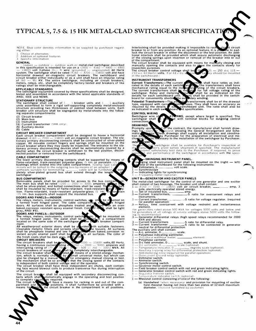
TYPICAL 5 , 7.5 & 1 5 HK METAL·CLAD SWITCHGEAR SPECIFICATIONS
NOl E. B l u e c o l o r d e n otes i n fo rm a t i o n to b e s u p p l i e d by p u rc h a s e r regardt n g e t t h e r: 1 . C h o i c e of a l te r n a tes 2 _ A d d i t i o n of o pt i o n a l featu res 3. S p e c i f t c m fo r m a t t o n
GENERAL ( i n d oo r - o ut d o o r - o u t d o o r w a l k t n ) metal-clad switchgear described
in this specification is intended for use on a 1 2 4 00 -- 4 1 60 - 4 800 - 6900 - 1 3 800) volt 3-phase (3--- 4) wire (g ro u n d e d - u n g ro u n d ed ) 60 Hertz system. The switchgear shal l be rated (4 1 60 �- 7200 -- 1 3 800) volt and have horizontal drawout a i r -magnetic circuit breakers. The switchboard and c i rcuit breaker either individual ly or as a un it shall have a n impu lse rating of (60 -- 95) KV. The entire switchgear, including air c i rcuit breakers, meters, relays, etc., shal l be completely factory tested and breakers of l i ke ratings sha l l be interchangeable. APPLICABLE STANDARDS The switchgear equi pment covered by these specifications sha l l be designed, tested and assembled in accordance with the latest appl icable standards of ANSI , I EEE and NEMA. STATIONARY STRUCTURE The switchgear shal l consist of ( ) breaker units and ( ) auxi l iary un its assembled to form a rigid self-supporting completely metal-enclosed structure providing two thicknesses of painted steel betwe_en units. Each breaker un it structure shall be segregated by metal-sheets 1nto the following separate compa rtments: (1) Circuit breaker (2) Main bus (3) I nstrument (4) Current transformer ( 5 H K o n l y) (5) Auxil iary device (6) Cable CIRCUIT BREAKER COMPARTMENT Each circuit breaker compartment shal l be designed to house a horizontal drawout 14 1 6 0 - 7?00 - 1 3 800) volt a i r-magnetic c i rcuit breaker. The stat ionary primary disconnecting contacts shall be constructed of si lver-plated copper. All movable contact fingers and springs sha l l be mounted on the circuit breaker where they may easily be inspected. The entrance to the stationary primary disconnecting devices sha l l be automatica l ly covered by a shutter when the circuit breaker is withdrawn to the test pos1t10n, d1scon· nected position or removed from the switchboard. CABLE COMPARTMENT The lower primary disconnecting contacts shal l be supported by means of f lame-retardant, track-resistant polyester glass ( 5 H K) or porcela in ( 1 5 H K ) bushings which extend into t h e cable compartment. ( C l a m p type c a b l e t e r m i n a l s w i l l b e b o l t e d t o t h e o utgo1 n g b u � b y m e a n s o f a n a d a pt e r ) ( ___ _ pot h e a d s s u i t a b l e fo r t e r m 1 n a t r n g _____ c a b l e w i l l be f u rn is h ed . ) A com-pletely si lver-plated ground bus shal l extend through the length of the switchgear. BUS COM PARTM ENT Removable panels shal l be provided for access to the bus compartment. The main bus shall be rated ( 1 2 00 - · 2000 - 3000; amperes. All bus bars shal l be silver-plated , and bolted connections sha l l be used. The conductors shal l be insu lated by means of f lame-retardant, track·resistant epoxy insulation. Flame-retardant, track- resistant polyester glass (5 H K l or porcela in ( 1 5 H K ) bus supports sha l l support the insulated bus.
DOORS AND PANELS-INDOOR The relays, meters, instruments, control switches, etc. shall be mounted on a formed front h inged paneL The cable compartment shal l have hi nged doors. All surfaces sha l l be phosphate treated and painted with an oven baked, corrosion resistant epoxy enamel f inish. Color of finish shall be l ight gray, ANSI #61.
DOORS AND PANELS-OUTDOOR The relays, meters, instruments, control switches, etc. shal l be mounted on a formed hinged paneL The panel shal l be mounted in a compartment located on the same side of the switchgear as the c ircuit breaker compa rtment. All weatherproof exterior doors shall be provided with suitable fasteners. Cleanable meta l l ic filters and screens shal l cover the louvers. All su rfaces shal l be phosphate treated and one finish coat of oven baked, corrosion resistant acrylic enamel painf shal l be applied to a l l su rfaces. The color of the fi nish coats sha l l be dark gray, ANSI #24. CIRCUIT BREAKERS The circuit breakers shall be rated 14 1 60 -- 7200 -- 1 3 800'1 volts, 60 Hertz, having a continuous cu rrent rating of 1 1 200 - 2000 - 30001 amperes and interrupting rating of <Ti - 2 5 0 -- 350 - · - oOO -- 750 - l OOIJl MVA. Al l c ircuit breakers of equal rating sha l l be completely interchangeable. The c ircuit breaker sha l l be operated by means of a stored-energy mechanism, which is normally charged by a small un iversal motor, but which can a lso be charged by a manual handle for emergency manual closing or test. The mechanism shal l be so arranged that the closing speed of the contacts is independent of both control voltage and of the operator. The circuit breaker sha l l have three independent arc chutes, each containing face wound blowout coils to produce transverse flux during interruption of the c ircuit. The circuit breaker shall be equi pped with secondary disconnecting contacts which shall automatically engage in the operating and test position to complete c i rcuits as requ i red. The circuit breaker shal l have a means for racking in and out of the compartment a nd between positions. I t sha l l furthermore be provided with a means for holding the circuit breaker in the compartment in a l l positions.
4 4
Interlocking sha l l be provided making i t impossible to rack a closed circuit breaker to or from any position. As an optional feature, it is possible to padlock the circuit breaker in either the disconnect or the test position. An additional interlock shall be provided which shall assure automatic discharging of the closing springs upon insertion or removal of the breaker into or out of the compartment. The c ircuit breaker shall be equipped with means tor manual ly closing and manua l ly opening the contacts and a lso to close the contacts slowly for inspection pu rposes. The c ircuit breaker control voltage sha l l be: (48 - 1 2 5 - 250 d - e ; 1 1 5 2 3 0 a -c . 6 0 H e rt z l volts. ! F o r 4 8 v d-e a p p l i ca t io n , battery s h o u l d b e m o u n t e d i n t h e s w i t c h b o a rd . )
INSTRUM ENT TRANSFORMERS Current Transformers-The current transformers shall have ratios as indicated in the details of each switchboard un it. The transformers shall have mechanical rating equal to the momentary rating of the c ircuit breakers. The cu rrent transformers shal l be insulated for full voltage rating of the switchgear. Relay and metering accuracy shal l be as indicated on the details for each switchboard un it. M eans shal l be provided in the switchboard for conveniently shorting the secondary winding. Potentia l Transformers-The potential transformers shall be of the drawout type, equipped with current l imiting fuses. They shall have an accuracy as req u ired by the deta i ls of each switchboard un it. The ratio shal l a lso be as ind icated in each switchboard un it specification.
CONTROL W I R I NG Switchgear wire shal l be #14 AWG, except where larger is specified. The switchgear shal l be provided with terminal blocks for outgoing control connections. DRAWI NGS Promptly upon award of the contract, the manufacturer sha l l furnish drawings for ( a p p ro v a l - record) showing the General Arrangement and Schematic Diagrams. These drawings sha l l supply all installation and coordination data requ i red by Purchaser for the preparation of e lectrical and mechanical deta ils necessary to the insta l l ation of the switchgear by Purchaser. I N SPECTION The c o m p l eted s w i t c h ge a r s h a l l b e a va i l a b l e for Pu rc h a s e r' s i n s p e c t i o n a t t h e m a n u f� ctu re_r's p l <1 n t b e f o re s h i p m e n t . i f s p e c i f i ed . T h e _ m a n u fa c t u re r sh a l l s u b m t t s a t r s fa ctory t e s t d a t a t o t h e P u rc h a s e r, i f r e q u 1 red, t o prove o pe ra t t o n and p e r fo r m a n c e of t h e switc h ge a r in a cc o rd a n c e with the s p e c i f t c a t t o n s .
U NIT A-SWINGING INSTRUMENT PANEL. A swinging steel instrument panel sha l l be mounted on the (right - left) hand end of the switchboard for the following instruments: 2 - Voltmeters, 0-____ volt scale. 1 - Synchroscope 2 - Indicating lights for synchronizing 1 --- F r e q u e n c y m et e r ( o p t t o n a l )
U N I T B-GENERATOR A N D EXCITER PANELS The metal-clad switchgear for the control of one generator and one exciter sha l l consist of two housings. The breaker un it shal l contain: 1 - 14 1 60 - 7 2 00 - 1 3 800) volt air circuit breaker, amp, 3
pole, electrically operated stored energy. 1 - Set of insulated bus, amp. 3 - Current transformers, -5 ratio for overcurrent relays and
instruments. 1 - Current transformer, _____ -5 ratio for voltage regulator. (req u i red
for paral le l operation) 3 - Relays, time overcurrent with voltage restra int and instantaneous
element. For g e n e r a t o rs ratecl a b_ove 500 KVA f o r voltages 5000 v o l t s and below a nd f o r g 0 n e ra t o rs of a l l r a t � n g s rlt s e rv 1 c e voltages a bove 5000 v o l t s t h e f o ! lowl l lg i s reco m rn e n c.J ed 3 - Generator d i fferential relays (high speed relays recommended for 2000
KVA and above). 3 - Current transformers -5 ratio for d i fferential relay. 3 - Current transformer -5 ratio to be connected in generator
neutral for d i fferential protection. The auxi l iary unit shall contain: 1 - A-c, ammeter, Q. _____ scale. 1 - Polyphase indicating wattmeter. 1 - P o l y ��h a',e w a t t h o u r m et e r, e l e m e n t 1 - Polyphase varmeter. 1 - D-e field ammeter, 0-_______ scale, and shunt. I -- D-e vo l t m et e r , 0-______ s c a l e ( o pt i o n a l ) . 1 -- T e M p e ra t u re i n d i c a t o r, 0 ____ degrees s c a l e (o pt i o n <'l l ) . 1 - A u x d 1 c H y t r 1 p p 1 n g rf: l a y f o r d 1 ffcre n t i a l protecti o n ( o pt i o n a l ) . 1 -- A n t 1 - m o to n n g r e l < l Y ( re q u 1 r e d f o r p a r a l l e l o pe ra t i o n ) . 1 --- O v e rc u r r e n t g ro u n d r e l a y ( o pt i o n a l ) 1 - Voltmeter switch. 1 - Ammeter switch. 1 - Synchronizing switch. 1 - Governor motor control switch. 1 - Field breaker control switch with red and green indicating lights. 1 - Generator breaker control switch with red and green indicating l ights. ' - Reg u i ::Jt o r t ra n s f e r s w i t c h l - T 12 rn p r:- r at u re • n d 1 c a t o r s w 1 t c h { o pt i o n a l \ . 1 - Rheostat control consisting o f o n e of the following:
(a) Handwheel ( w h e n necessa ry) and provision for mounting of exciter fie ld rheostat having not more than two plates of 1 2-inch maximum diameter. ( r h co � t a t f u r n i s h e d b y cu <::. t o m e r)
www . El
ectric
alPar
tMan
uals
. com
www . El
ectric
alPar
tMan
uals
. com
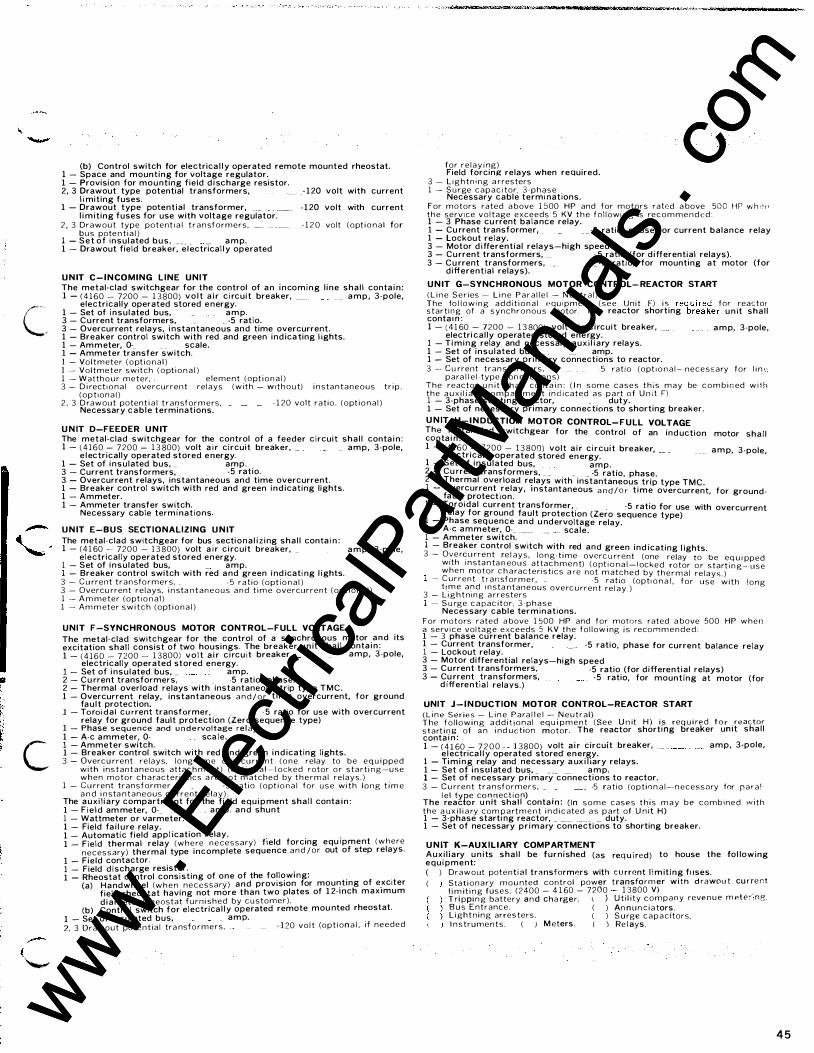
C�
c
-( ""-"
(b) Control switch for electrica l ly operated remote mounted rheostat. 1 - Space and mounting for voltage regulator. 1 - Provision for mounting field d ischarge resistor. 2, 3 Drawout type potential transformers, ___ _ - 120 volt with current
l i miting fuses. 1 - Drawout type potential transformer, _ - 120 volt with current
l im iting fuses for use with voltage regulator. 2 , 3 Drawout type potent 1 a l t r a n sformers, _ - 1 2 0 volt ( o pt i o n a l for
b u s pote n t i a l ) 1 - Set of insulated bus , ____ _ __ amp. 1 - Drawout field breaker, e lectrical ly operated
U N IT C-INCOMING LINE UNIT The metal-clad switchgear for the control of an incoming l ine shal l conta in : 1 - ( 4 1 6 0 - 7200 - 1 3 800) vo lt a i r c i rcuit breaker, __ _ __ amp, 3-pole,
electrically operated stored energy. 1 - Set of insulated bus, amp. 3 - Current transformers, _ -5 ratio. 3 - Overcurrent relays, instantaneous and time overcurrent. 1 - Breaker control switch with red and green ind icating l ights. 1 - Ammeter, 0·_ _ scale. 1 - Ammeter transfer switch. I - Vo l t m eter ( o pt i o n a l ) I -- Voltmeter switch ( o pt i o n a l ) 1 - W alth o u r meter, element (opt i o n a l ) 3 - D i rect i o n a l overcurrent relays ( w i t h - W i t h o u t) i n sta n t a n e o u s t r i p .
( o p t 1 o n a l ) 2 , 3 D rawout potent i a l t r a n sf o r m e rs , - 1 20 volt rat io. ( o pt i o n a l )
Necessary cab le terminations.
U N IT D-FEEDER U N IT The metal-clad switchgear for the control of a feeder circuit shal l conta in : 1 - ( 4 1 6 0 - 7200 - 1 3 800) volt a i r circuit breaker, _ _ amp, 3-pole,
e lectrically operated stored energy. 1 - Set of insulated bus, _ amp. 3 - Current transformers, _ -5 ratio. 3 - Overcurrent relays, instantaneous and time overcurrent. 1 - Breaker control switch with red and green ind icating lights. 1 - Ammeter. 1 - Ammeter transfer switch.
Necessary cable terminations
U N IT E-BUS SECTIONALIZING U N IT The metal-clad switchgear for bus sectional iz ing shal l conta in : 1 - (41 60 - 7200 - 1 3 800) volt a i r c ircuit breaker, _ amp, 3-pole,
electrically operated stored energy. 1 - Set of insulated bus, _ amp. 1 - Breaker control switch with red and green ind icati ng l ights. 3 - C u rrent t r a n sfo r m e r s , - 5 r a t i o ( o pt i o n a l ) 3 - Overcu rrent relays, i n sta n t a n e o u s a n d t i m e overcurrent ( o pt i o n a l ) 1 - A m meter ( o pt 1 o n a l ) I - Am m eter s w i t c h ( o pt i o n a l )
UNIT F-SYNCHRONOUS MOTOR CONTROL-FULL VOLTAGE The metal-clad switchgear for the control of a synchronous motor and its excitation shal l consist of two housings. The breaker un it shal l conta in : 1 - ( 4 1 6 0 - 7 200 - 1 3800) volt a i r c ircuit breaker, amp, 3-pole,
electrically operated stored energy. 1 - Set of insulated bus, _ amp. 2 - Cu rrent transformers, _ -5 ratio, phase. 2 - Thermal overload relays with instantaneous trip type TMC. 1 - Overcurrent relay, instantaneous a n d / o r t ime overcurrent, for ground
fault protection. 1 - Toro i da l cu rrent transformer, __ _ -5 ratio for use with overcurrent
relay for ground fault protection (Zero sequence type) 1 - Phase sequence and u n d e rvoltage rela y . 1 - A-c ammeter, 0- sca le. 1 - Ammeter switch. 1 - Breaker control switch with red and green ind icating lights. 3 - Overc u rrent relays, l o ng-t i m e ove rc_u rrent ( o n e relay to b e e_q u i pped
with i n s t a n t a n e o u s attac h m ent) ( o pt 1 o n a l -· l ocked rotor o r sta rtmg-use w h e n motor c h a racterist ics a re n o t m at c h ed by t h e r m a l relays.)
1 - C u rrent transformer - 5 ratio ( o pt i o n a l for u s e w i t h l o n g t i m e a n d i n sta n t a n e o u s c u rrent relay) . .
The auxi l iary compartment for the field equ ipment shal l conta 1n : 1 - Fie ld am meter, 0-_ amp. and shunt 1 - Wattmeter or varmeter. 1 - Field fa i l ure relay. 1 - Automatic field appl ication relay. . . . 1 - Field thermal relay ( w h e re n e ce s s a ry) field forc1ng equ ipment ( w h e re
necessary) thermal type incomplete sequence a n d / o r out of step relays. 1 - Field contactor. 1 - Field discharge resistor. . 1 - Rheostat control consisting of one of the followmg: .
(a) Handwheel (w h e n n e c e s s a ry) and provision for mou�ting of e.xc1ter field rheostat having not more than two plates of 1 2- lnch max1mum diameter ( r h eostat f u r n i s h e d by c u stomer).
(b) Control switch for electrica l ly operated remote mou nted rheostat. 1 - Set of insulated bus, amp. 2, 3 Drawout pot e n t i a l tra nsfo r m e r s . - 1 20 v o l t (opt i on a l , i f n e e d e d
for r e l a y i ng) Field forcing relays when required.
3 - L i g h t n i n g a rresters I - S u rge c a p a c itor, 3 - p h a s e
Necessary cable termi nations. For motors rated a bove 1 500 HP and for motors rated a bove 500 HP w h co 1• t h e serv1ce v o l tage exceeds 5 KV t h e f o l l owmg 1s rec o m m e n d e d : 1 - 3 Phase cu rrent balance relay. 1 - Cu rrent transformer, _ -5 ratio, phase for current balance relay 1 - Lockout relay. 3 - Motor d ifferential relays-high speed 3 - Current transformers, _ _ - 5 ratio (for differential relays). 3 - Cu rrent transformers, __ _ -5 ratio, for mounting at motor (for
differential relays).
U N IT G-SYNCHRONOUS MOTOR CONTROL- REACTOR START ( L i n e S e r i es - L i n e P a r a l l e l - N e u t r a l ) The _fo l lo w i n g a d d i t i o n a l e q u i p m e n t ( s e e U n i t F) i s req u i red for reactor startl l] g of a s y n c h r o n o u s motor. The reactor shorting breaker un it shal l contam : 1 - (41 60 - 7200 - 1 3 800) volt a i r c ircuit breaker, _ amp, 3-pole,
electrical ly operated stored energy. 1 - Timing relay and necessary auxi l iary relays. 1 - Set of insulated bus, __ _ amp. 1 - Set of necessary primary connections to reactor. 3 - C u rrent t r a n sformers , - 5 ratio ( o pt i o n a l - n e c e s s a ry for l i n •.
p a ra l l e l -type con necti o n s) T h e reactor u n it s h a l l cont_a i n_: ( I n s o m e c a s e s t h i s m a y be c o m b i n ed w 1 t h t h e a u x i l i a ry c o m p a rt m e n t 1 n d 1 cated a s p a rt o f U n it F) 1 - 3-phase startmg reactor, _ duty. 1 - Set of necessary primary connections to shorting breaker. U N IT H - I N DUCTION MOTOR CONTROL- FULL VOLTAGE ���
ta7'
n�tal-clad switchgear for the control of an induction motor shal l
1 - ( 4 1 6 0 - 7200 - 1 3 800) volt a i r circuit breaker amp, 3-pole, electrically operated stored energy. ' 1 - Set of insulated bus, amp. 2 - Cu rrent transformers, _ _ _ _ -5 ratio, phase. 2 - Thermal overload relays with instantaneous trip type TMC. 1 - Overcurrent _relay, mstantaneous a n d / o r t ime overcurrent for ground-fault protectiOn. ' 1 - Toroidal current transformer, _ -5 ratio for use with overcurrent relay for ground fault protection (Zero sequence type) 1 - Phase sequence and u ndervoltage relay. 1 - A-c ammeter, 0- _ ___ · - sca le. 1 - Ammeter switch.
---1 - Breaker control switch with red and green ind icating l ights. 3 - O�e r� u rrent re l ay s , l o n g - t i m e ovcrc_u rrent (one relay to be eq u i pped w1th I n sta n ta n eo u s at�ac_ h m e n t) ( o rt 1 o n a l - l ocked rotor o r start i n g-- u s e w h e n motor c h a racter 1st 1cs a re not m at_ched by t h e r m a l relays.) - � u r rent t r a n sf o r m e r, _ - 5 rat1o (optJ o n a l , for u s e with l o ng t 1 _m e a � d I n sta n t a n e o u s overc u rrent rel a y . ) 3 - L 1 g h t n 1 n g a rresters 1 - S u rge c a pac itor, 3 - p h a s e
Necessary cable terminations. For m � t o rs rated a bove 1 �00 HP and for motors rated a bove 500 HP w h e n a serv 1 c e voltage exceeds 5 KV t h e f o l l ow i ng i s reco M m e n d e d : 1 - 3 phase current balance relay. 1 - Current transformer, __ -5 ratio, phase for current balance relay 1 - Lockout relay. 3 - Motor differential relays-high speed 3 - Current transformers, -5 ratio (for differential relays) 3 - Cu rrent transformers, ·5 ratio, for mounting at motor (for
d 1 fferent1al relays.)
UNIT J - I N DUCTION MOTOR CONTROL-REACTOR START (L i n e Series - L i n e P a ra l l e l - N e u t r a l ) T h e f o l l o w i n g a d d it i o n a l eq u i p m e n t (See U n it H ) i? re� u i re d f o r .reactor s t a rt i n g of a n i nd u ction motor . The reactor shortmg breaker umt shal l conta in : 1 - ( 4 1 60 - 7 2 0 0 - - 1 3800) volt a i r circuit breaker, __ _ _ amp, 3-pole,
e lectrica l ly operated stored energy. 1 - Timing relay and necessary a ux i l iary relays. 1 - Set of insulated bus, _ __ _ amp. 1 - Set of necessary primary connections to reactor.
3 - C u rrent t r a n sformers. _ -5 ra t io (option a l - n ecess�ry for r a r a !
The 1�!�6fo8r c��i�e
sc���r)
conta in : ( In s o m e c a s e s t h i s m a y b e c o m b i n e d with t h e a ux i l i a ry c o m p a rt m e n t i n d i c ated a s p a rt of U n it H) 1 - 3-phase startmg reactor, _ _____ _ _ _ duty. 1 - Set of necessary primary connections to shorting breaker.
U N IT K-AUXILIARY COMPARTMENT Auxi l iary un its shal l be furnished (as req uired) to house the fol lowing equipment: ( ) D r a w o ut pote nt ia l tr3nsformers with cu rrent l im iting fuses. ( Sta t i o n a ry m o u nted control power transformer with d rawou t cu rre nt
l i m it i n g fuses. (2400 - 4 1 60 - 7200 - 1 3800 V) . T r i ppin g battery and cha rger. \ ) U t i l ity c o m p a n y reve n u e m P\e,,ng_
B u s E n t r a n c e . ( ) An n u nc i a tors . L i g h t n i n g arresters. ( ) S u rge c a p a c itors. I n s t r u m e n t s . ( ! M eters . ( l Re l ays .
45 www . El
ectric
alPar
tMan
uals
. com
www . El
ectric
alPar
tMan
uals
. com
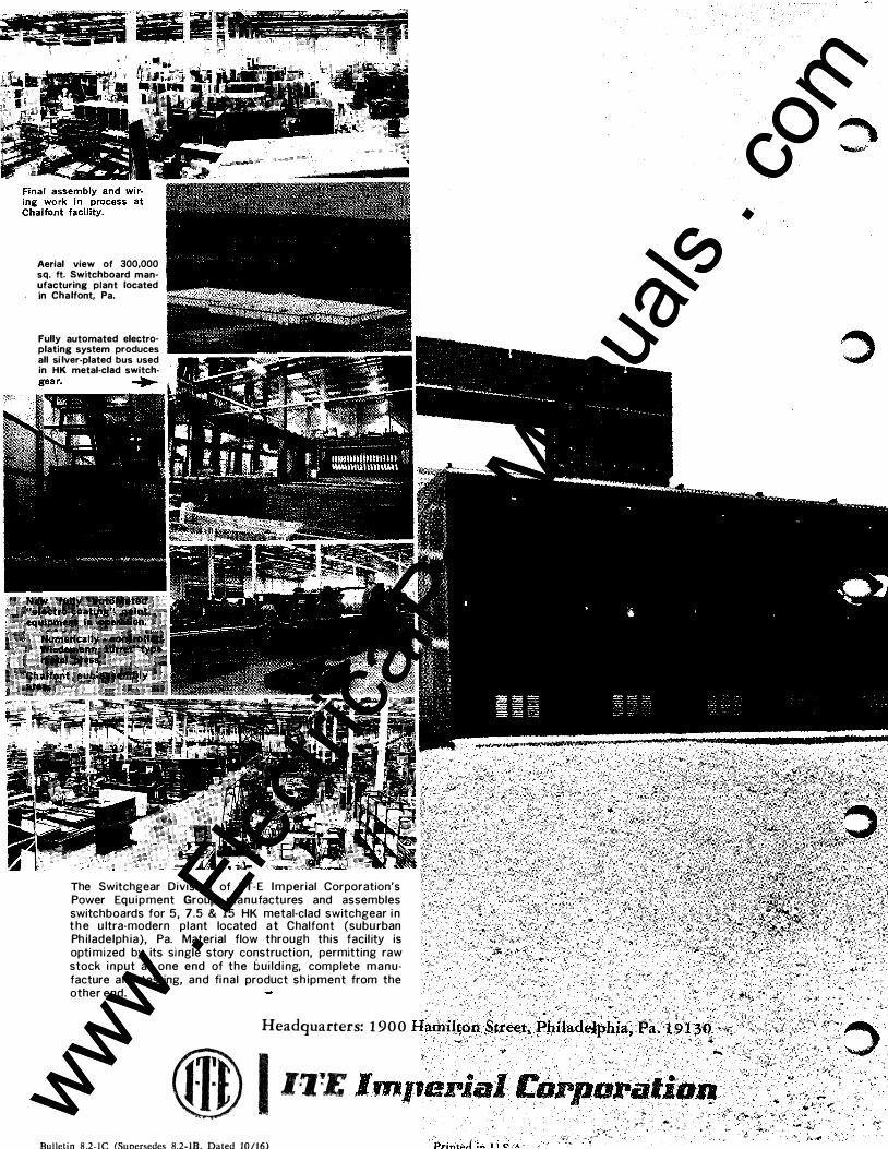
Aerial view of 300,000 sq. ft. Switchboard man· ufacturing plant located in Chalfont, Pa.
Fully automated electro· plating system produces all si lver-plated bus used in HK metal-clad switch·
�
The Switchgear Division of ITE Im perial Corporation's Power Equipment Group manufactures and assembles switchboards for 5, 7.5 & 15 HK metal-clad switchgear i n t h e u ltra-modern plant located a t Chalfont (subu rban Ph iladelph ia), Pa. Material flow through this facil ity is opti mized by its si ngle story construction, permitting raw stock i nput at one end of the b ui ld i ng, complete manu· facture and testing, and fi nal product sh ipment from the other end.
]" - '"-
Headquarters: 1 900 Hamilton $u·eet, ?hiladelphia, Pa>i 91 3'0 ·�(
Qj}) I J!J!£ lm�e;i�; t:orpciNiio; ... �
Bulletin 8 .2-IC (Supersedes 8.2-IB, Dated 10/16)
-.,-"'; .. _ .. � �
• . www . El
ectric
alPar
tMan
uals
. com
www . El
ectric
alPar
tMan
uals
. com