Embed Size (px)
Citation preview

U-Sand® Maintenance Manual U-Series
800-392-8894 March 2012
3
Contents BACKER PAD REPLACEMENT ........................................... 4 BELT REPLACEMENT .......................................................... 6 BELT COVER REPLACEMENT ............................................ 9 DUST SKIRT REPLACEMENT ........................................... 12 HANDLE ASSEMBLY REPLACEMENT ............................ 14 HANDLE GRIP REPLACEMENT ........................................ 17 LOWER SHAFT REPLACEMENT....................................... 19 MOTOR COVER REPLACEMENT ..................................... 21 MOTOR FAN REPLACEMENT ........................................... 23 SPINDLE REPLACEMENT .................................................. 25 SWITCH REPLACEMENT ................................................... 27 SWITCH COVER REPLACEMENT..................................... 31 VACUUM PORT.................................................................... 33 WHEEL REPLACEMENT .................................................... 34 WHEEL BRACKET REPLACEMENT ................................. 36 PARTS LISTS ........................................................................ 38
US-146 ................................................................................ 38
US-PRO MODEL ............................................................... 44
BT700 MODEL .................................................................. 51
4
BACKER PAD REPLACEMENT
REASONS TO CHANGE BACKER PAD
TOOLS NEEDED QUANTITY TOOL NAME
1 3/4” Open end wrench
PARTS NEEDED QTY PART NUMBER NAME
1 BP6 6” BACKER PAD
BACKER PAD REPLACEMENT
PICS
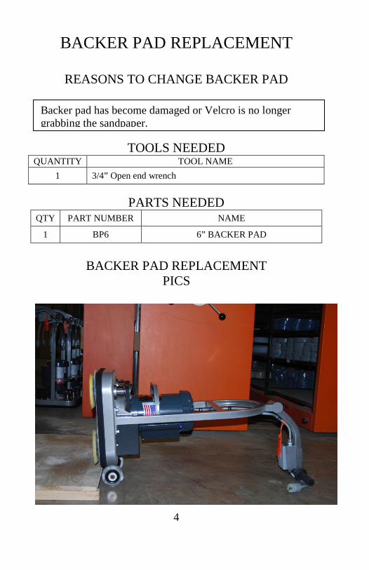
Backer pad has become damaged or Velcro is no longer grabbing the sandpaper.
5
PROCEDURE MAKE SURE SWITCH IS TURNED OFF AND
MACHINE IS UNPLUGGED.
STEP PART DESCRIPTION
1 Remove Vacuum attachment, lean machine back on wheels and rest on handle.
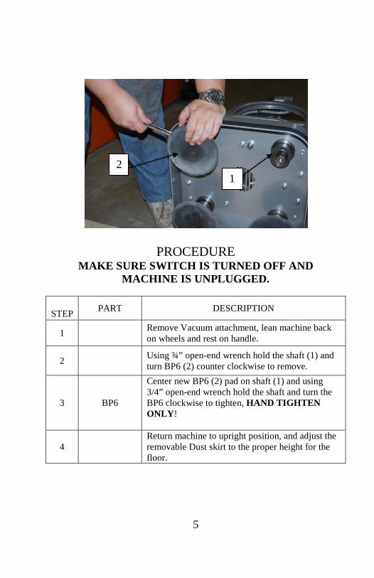
2 Using ¾” open-end wrench hold the shaft (1) and turn BP6 (2) counter clockwise to remove.
3 BP6
Center new BP6 (2) pad on shaft (1) and using 3/4” open-end wrench hold the shaft and turn the BP6 clockwise to tighten, HAND TIGHTEN ONLY!
4 Return machine to upright position, and adjust the removable Dust skirt to the proper height for the floor.
1 2

6
BELT REPLACEMENT
Reason to change Belt REASONS TO CHANGE BE
TOOLS NEEDED QUANTITY TOOL NAME
1 3/16” hex wrench-Belt Cover bolts 1 5/16” hex wrench-housing and motor mounting bolts 1 7/32” hex wrench-impeller mounting bolt 1 Pliers, flat screwdriver, and an adjustable wrench
PARTS NEEDED
QTY PART NUMBER NAME 1 PCB-146 Poly Cog Belt 1 US-152 Gasket
Shredded Belt, Squealing Belt, Belt Slipping, Broken Belt
7
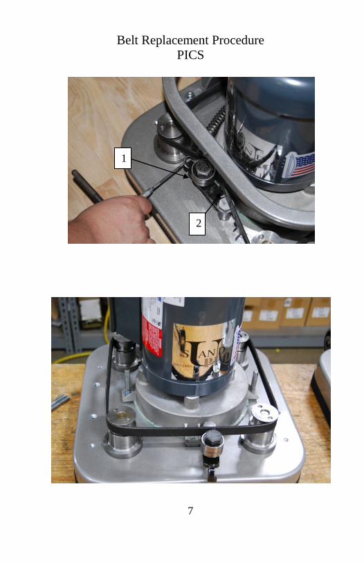
Belt Replacement Procedure PICS
1
2
8
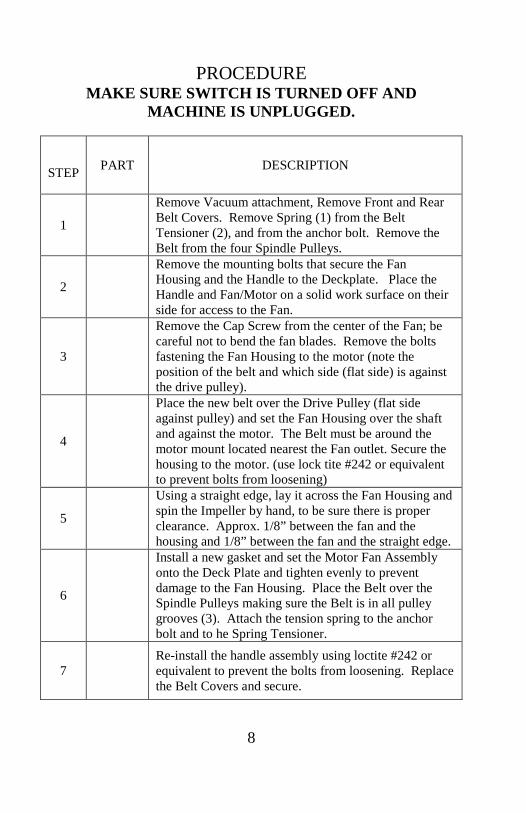
PROCEDURE
MAKE SURE SWITCH IS TURNED OFF AND MACHINE IS UNPLUGGED.
STEP PART DESCRIPTION
1
Remove Vacuum attachment, Remove Front and Rear Belt Covers. Remove Spring (1) from the Belt Tensioner (2), and from the anchor bolt. Remove the Belt from the four Spindle Pulleys.
2
Remove the mounting bolts that secure the Fan Housing and the Handle to the Deckplate. Place the Handle and Fan/Motor on a solid work surface on their side for access to the Fan.
3
Remove the Cap Screw from the center of the Fan; be careful not to bend the fan blades. Remove the bolts fastening the Fan Housing to the motor (note the position of the belt and which side (flat side) is against the drive pulley).
4
Place the new belt over the Drive Pulley (flat side against pulley) and set the Fan Housing over the shaft and against the motor. The Belt must be around the motor mount located nearest the Fan outlet. Secure the housing to the motor. (use lock tite #242 or equivalent to prevent bolts from loosening)
5
Using a straight edge, lay it across the Fan Housing and spin the Impeller by hand, to be sure there is proper clearance. Approx. 1/8” between the fan and the housing and 1/8” between the fan and the straight edge.
6
Install a new gasket and set the Motor Fan Assembly onto the Deck Plate and tighten evenly to prevent damage to the Fan Housing. Place the Belt over the Spindle Pulleys making sure the Belt is in all pulley grooves (3). Attach the tension spring to the anchor bolt and to he Spring Tensioner.
7 Re-install the handle assembly using loctite #242 or equivalent to prevent the bolts from loosening. Replace the Belt Covers and secure.

9
BELT COVER REPLACEMENT
REASONS TO CHANGE Belt Cover
TOOLS NEEDED QUANTITY TOOL NAME
1 3/16” hex wrench-Belt Cover bolts 1 1/8” High speed steel drill bit 1 POP rivet gun
PARTS NEEDED
QTY PART NUMBER NAME
1 CH-102-146-reference part list for
your model unit
Set replacement Belt Covers
4 HW-RVT POP rivets (only needed if serial tag is missing or damaged)
6 HW-CS ¼ Belt Cover bolts (only needed if damaged or missing)
6 HW-FW 3/8 Washers (only needed if damaged or missing)
Broken Tabs, Worn Safety Tag, Damaged Belt Cover
10
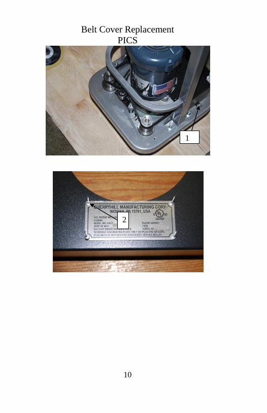
Belt Cover Replacement PICS
1
2

11
PROCEDURE MAKE SURE SWITCH IS TURNED OFF AND
MACHINE IS UNPLUGGED.
STEP PART DESCRIPTION
1
With machine in the upright position (sanding position)
Use 3/16” hex wrench to remove (6) Belt Cover bolts and washers (1)
Remove used belt covers from machine
2
Inspect Belt Cover bolts for worn or damaged threads (If replacement belt covers do not have a serial tag) Use 1/8” drill bit to remove serial number tag from
used front belt cover by drilling rivets in the center to remove (DO NOT DO THIS WHILE BELT COVER
IS ON MACHINE, COULD CAUSE POSSIBLE DAMAGE TO BELT)
3
Replace Rear Belt Cover by placing Fan port cut out over the Fan housing port. Insert (2) bolts with
washers into tabs on belt cover tighten (DO NOT OVER TIGHTEN, BOLTS WILL STRIP)
4
(If installing new serial tag only) Use (4) new POP rivets (2) to install serial number tag
in prefabricated holes located on top of front belt cover (centered) NOTE: THIS TAG MUST BE
PRESENT ON MACHINE Use POP rivet gun to fasten rivets
5
Replace front belt cover by lining up bolt holes on top of front and rear covers
Insert (2) bolts and washers into bolt holes (do not tighten, use only for alignment)
6
Insert remaining belt cover bolts and washers into tabs on front belt cover
Tighten all belt cover bolts (DO NOT OVER TIGHTEN, BOLTS WILL STRIP)

12
DUST SKIRT REPLACEMENT
REASONS TO CHANGE Dust Skirt
TOOLS NEEDED QUANTITY TOOL NAME
PARTS NEEDED
QTY PART NUMBER NAME 1 US115-146 Dust Skirt (removable and adjustable) 1 US115-146B Dust Skirt VD (attaches permanently to
Deck plate)
DUST SKIRT REPLACEMENT PICS
Dust Skirt is worn, cracked or damaged. Be sure to inspect dust skirt to ensure that both sides have been used, as you can flip dust skirt over before replacement.
1
2

13
PROCEDURE MAKE SURE SWITCH IS TURNED OFF AND
MACHINE IS UNPLUGGED.
STEP PART DESCRIPTION
1 Remove old Dust Skirt by pulling apart from deck plate. Re-align the new Dust Skirt level with the floor and press into place.
2
Remove the Dust Skirt that came attached to the Deck plate if it no longer has Velcro adhesion for the removable part or is damaged by a rental customer. By Pulling and scraping away from the Deck plate and using mineral spirits or similar solvent to completely clean the surface prior to adhering the replacement dust skirt.
3
Clean surface of the deck plate thoroughly and dry completely. Pull the paper backer from the replacement dust skirt (US-115-146B) and adhere to the Deck plate 1/8” from the bottom edge.
14
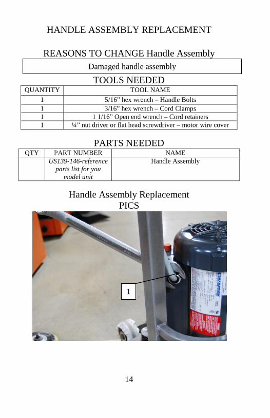
HANDLE ASSEMBLY REPLACEMENT
REASONS TO CHANGE Handle Assembly
TOOLS NEEDED QUANTITY TOOL NAME
1 5/16” hex wrench – Handle Bolts 1 3/16” hex wrench – Cord Clamps 1 1 1/16” Open end wrench – Cord retainers 1 ¼” nut driver or flat head screwdriver – motor wire cover
PARTS NEEDED
QTY PART NUMBER NAME US139-146-reference
parts list for you model unit
Handle Assembly
Handle Assembly Replacement
PICS
Damaged handle assembly
1
15
2
2
16
PROCEDURE MAKE SURE SWITCH IS TURNED OFF AND
MACHINE IS UNPLUGGED.
STEP PART DESCRIPTION
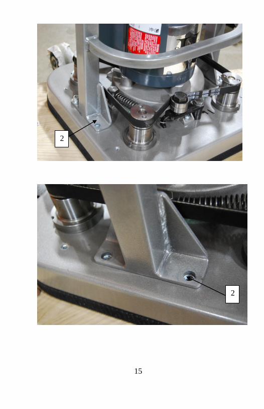
1
Ensure that machine is unplugged, remove Vacuum attachment
Remove belt covers Remove the motor wire cover Remove only RED wire nuts Loosen the cord retainers (1)
2 Pull the cord out of the cord retainer
3 Remove the handle bolts and washers (2) Pull old handle assembly from machine
4
Install new handle assembly over mounting holes (3) Using LOCTITE #242 or equivalent on bolt threads
Install handle bolts and washers and tighten Install belt covers
5
Insert cord into cord retainer until able to see wire coating
If needed loosen cord restraints to gain more wire take care not to pull too much wire.
Tighten cord retainer Wire in the following order using RED wire nuts
removed earlier P1 to BLACK cord wire
YELLOW BLACK and White motor wire to WHITE cord wire
GREEN (ground) to GREEN (ground)
17
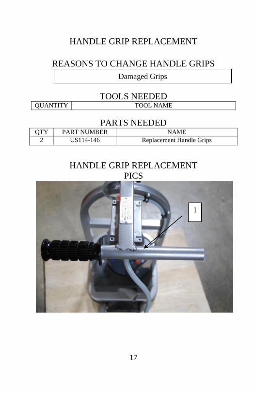
HANDLE GRIP REPLACEMENT
REASONS TO CHANGE HANDLE GRIPS
TOOLS NEEDED QUANTITY TOOL NAME
PARTS NEEDED
QTY PART NUMBER NAME 2 US114-146 Replacement Handle Grips
HANDLE GRIP REPLACEMENT PICS
Damaged Grips
1
18
PROCEDURE MAKE SURE SWITCH IS TURNED OFF AND
MACHINE IS UNPLUGGED.
STEP PART DESCRIPTION
1 Remove old grips (1)
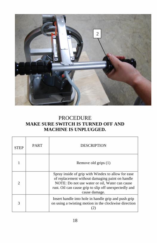
2
Spray inside of grip with Windex to allow for ease of replacement without damaging paint on handle NOTE: Do not use water or oil, Water can cause
rust. Oil can cause grip to slip off unexpectedly and cause damage.
3 Insert handle into hole in handle grip and push grip
on using a twisting motion in the clockwise direction (2)
2
19
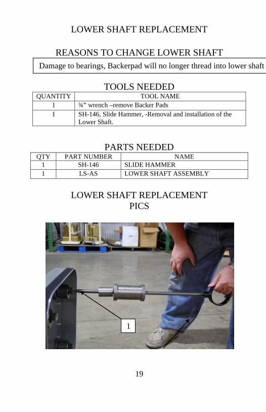
LOWER SHAFT REPLACEMENT
REASONS TO CHANGE LOWER SHAFT
TOOLS NEEDED QUANTITY TOOL NAME
1 ¾” wrench –remove Backer Pads 1 SH-146, Slide Hammer, -Removal and installation of the
Lower Shaft.
PARTS NEEDED QTY PART NUMBER NAME
1 SH-146 SLIDE HAMMER 1 LS-AS LOWER SHAFT ASSEMBLY
LOWER SHAFT REPLACEMENT
PICS
Damage to bearings, Backerpad will no longer thread into lower shaft
1
20
PROCEDURE MAKE SURE SWITCH IS TURNED OFF AND
MACHINE IS UNPLUGGED.
STEP PART DESCRIPTION
1 Tilt unit back on the wheels and rest on the handle. Remove the (4) Backer Pads (BP6) from the shaft assembly using a ¾” wrench.
2
Thread the Slide Hammer (SH-146) (1) into the lower shaft until tight. Brace the machine to prevent it from moving and pull the hammer on the slide toward you with enough force to remove the Lower Shaft Assembly. (May need the assistance of WD-40 or comparable lubricant for removal)
3
Remove the old assembly from the Slide Hammer and install the new assembly onto the Slide Hammer.
4
Using the Slide Hammer, install the new Lower Shaft Assembly into the Spindle. Be sure the Bearings are seated completely by replacing the (4) Backer Pads and operating the unit on a test board to insure all pads are contacting the board’s surface.
21
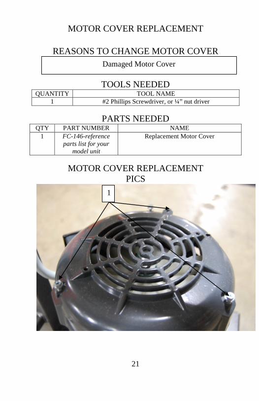
MOTOR COVER REPLACEMENT
REASONS TO CHANGE MOTOR COVER
TOOLS NEEDED QUANTITY TOOL NAME
1 #2 Phillips Screwdriver, or ¼” nut driver
PARTS NEEDED QTY PART NUMBER NAME
1 FC-146-reference parts list for your
model unit
Replacement Motor Cover
MOTOR COVER REPLACEMENT
PICS
Damaged Motor Cover
1
22
PROCEDURE MAKE SURE SWITCH IS TURNED OFF AND
MACHINE IS UNPLUGGED.
STEP PART DESCRIPTION
1
Remove (3) retaining screws (1) holding old motor cover in place (Take note of how the motor cover is sitting, as the new one will have to be installed
in the same position)
2 Remove old motor cover and replace with new motor cover in the same position as the old one
3 Install (3) retaining screws until tight (Do Not Over tighten, damage to motor cover could occur)
23
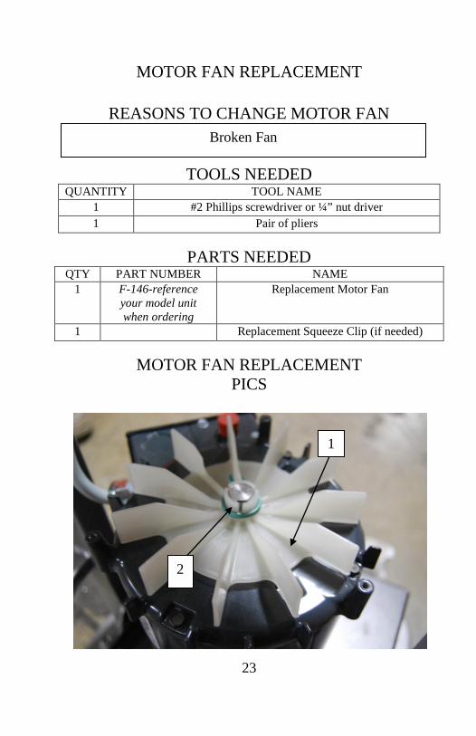
MOTOR FAN REPLACEMENT
REASONS TO CHANGE MOTOR FAN
TOOLS NEEDED QUANTITY TOOL NAME
1 #2 Phillips screwdriver or ¼” nut driver 1 Pair of pliers
PARTS NEEDED
QTY PART NUMBER NAME 1 F-146-reference
your model unit when ordering
Replacement Motor Fan
1 Replacement Squeeze Clip (if needed)
MOTOR FAN REPLACEMENT PICS
Broken Fan
1
2
24
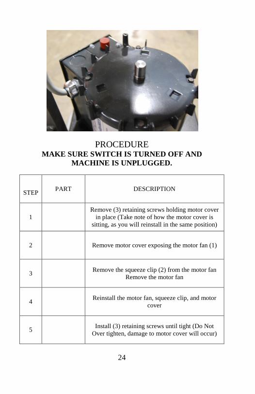
PROCEDURE MAKE SURE SWITCH IS TURNED OFF AND
MACHINE IS UNPLUGGED.
STEP PART DESCRIPTION
1 Remove (3) retaining screws holding motor cover
in place (Take note of how the motor cover is sitting, as you will reinstall in the same position)
2 Remove motor cover exposing the motor fan (1)
3 Remove the squeeze clip (2) from the motor fan Remove the motor fan
4 Reinstall the motor fan, squeeze clip, and motor cover
5 Install (3) retaining screws until tight (Do Not Over tighten, damage to motor cover will occur)
25
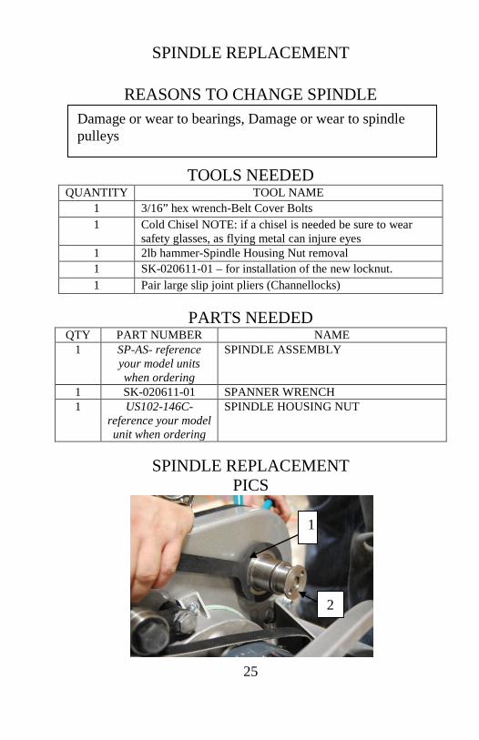
SPINDLE REPLACEMENT
REASONS TO CHANGE SPINDLE
TOOLS NEEDED QUANTITY TOOL NAME
1 3/16” hex wrench-Belt Cover Bolts 1 Cold Chisel NOTE: if a chisel is needed be sure to wear
safety glasses, as flying metal can injure eyes 1 2lb hammer-Spindle Housing Nut removal 1 SK-020611-01 – for installation of the new locknut. 1 Pair large slip joint pliers (Channellocks)
PARTS NEEDED
QTY PART NUMBER NAME 1 SP-AS- reference
your model units when ordering
SPINDLE ASSEMBLY
1 SK-020611-01 SPANNER WRENCH 1 US102-146C-
reference your model unit when ordering
SPINDLE HOUSING NUT
SPINDLE REPLACEMENT
PICS
Damage or wear to bearings, Damage or wear to spindle pulleys
1
2

26
PROCEDURE MAKE SURE SWITCH IS TURNED OFF AND
MACHINE IS UNPLUGGED.
STEP PART DESCRIPTION
1 Remove the Vacuum attachment, Belt Covers, Spring Tensioner, and belt
2
Tilt machine back onto the handle. Grip spindle housing (located tight against the deckplate) and use the spanner wrench (1) to see if Spindle Housing Nut will come loose. If Spindle Housing Nut (2) will not loosen, place cold chisel into one of the divots in Spindle Housing Nut and strike with 2lb hammer with enough force to break the nut.
3 Remove old spindle from the deckplate, and replace with new spindle
4 Install new lock nut using Loctite #242 or equivalent thread locker, tighten using spanner wrench and slip joint pliers.
5 Reinstall Belt, Spring Tensioner, and Belt Covers
27
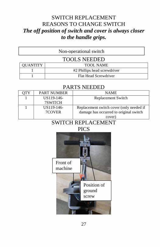
SWITCH REPLACEMENT REASONS TO CHANGE SWITCH
The off position of switch and cover is always closer to the handle grips.
TOOLS NEEDED QUANTITY TOOL NAME
1 #2 Phillips head screwdriver 1 Flat Head Screwdriver
PARTS NEEDED
QTY PART NUMBER NAME 1 US119-146-
7SWITCH Replacement Switch
1 US119-146-7COVER
Replacement switch cover (only needed if damage has occurred to original switch
cover) SWITCH REPLACEMENT
PICS
Non-operational switch
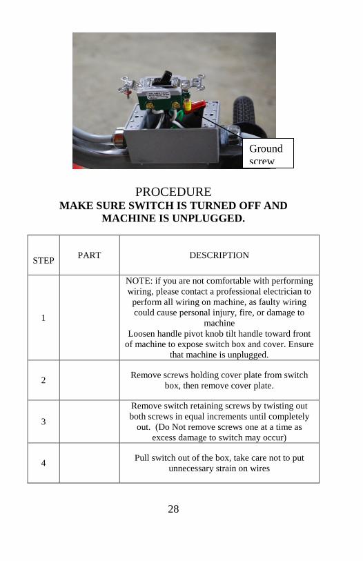
Position of ground screw
Front of machine
28
PROCEDURE MAKE SURE SWITCH IS TURNED OFF AND
MACHINE IS UNPLUGGED.
STEP PART DESCRIPTION
1
NOTE: if you are not comfortable with performing wiring, please contact a professional electrician to
perform all wiring on machine, as faulty wiring could cause personal injury, fire, or damage to
machine Loosen handle pivot knob tilt handle toward front
of machine to expose switch box and cover. Ensure that machine is unplugged.
2 Remove screws holding cover plate from switch box, then remove cover plate.
3
Remove switch retaining screws by twisting out both screws in equal increments until completely
out. (Do Not remove screws one at a time as excess damage to switch may occur)
4 Pull switch out of the box, take care not to put unnecessary strain on wires
Ground screw
29
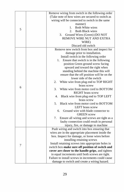
5
Remove wiring from switch in the following order (Take note of how wires are secured to switch as wiring will be connected to switch in the same
manner) 1. Both White wires 2. Both Black wires
3. Ground Wires (Green) (DO NOT REMOVE WIRE NUT AND EXTRA
WIRE) Discard old switch
6
Remove new switch from box and inspect for damage prior to installation.
Install switch in the following order 1. Ensure that switch is in the following
position Green ground screw facing upward and toward the right when
standing behind the machine this will ensure that the off position will be on the
lower side of the switch 2. White wire from plug end to TOP RIGHT
brass screw 3. White wire from motor cord to BOTTOM
RIGHT brass screw 4. Black wire from plug end to TOP LEFT
brass screw 5. Black wire from motor cord to BOTTOM
LEFT brass screw 6. Ground wire with blade connector to
GREEN screw 7. Ensure all wiring and screws are tight as a
faulty connection could result in personal injury, fire, or damage to machine
7
Push wiring and switch into box ensuring that wires are in the appropriate placement inside the box. Inspect for damage, or loose wires before
installing retaining screws Install retaining screws into appropriate holes in
switch box-make sure off position of switch and cover are closer to the handle grips, and tighten
in equal increments until both screws are tight. Failure to install screws in increments could cause
damage to switch and create a wiring hazard.

30
8
Line up switch cover prongs with flipper on switch, make sure switch on/off matches the switch position you are covering. Push cover down tight
to box and install cover retaining screws Test switch with machine unplugged before using
machine
31
SWITCH COVER REPLACEMENT
REASONS TO CHANGE SWITCH COVER
TOOLS NEEDED QUANTITY TOOL NAME
1 #2 Phillips screwdriver
PARTS NEEDED QTY PART NUMBER NAME
1 US119-146-7COVER
Replacement Switch Cover
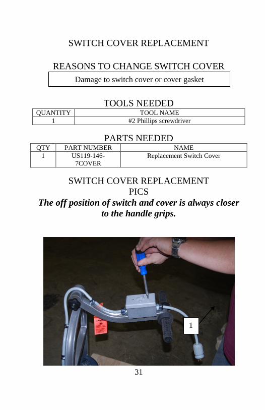
SWITCH COVER REPLACEMENT
PICS The off position of switch and cover is always closer
to the handle grips.
Damage to switch cover or cover gasket
1
32
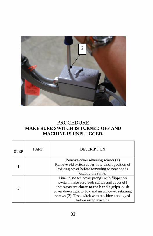
PROCEDURE MAKE SURE SWITCH IS TURNED OFF AND
MACHINE IS UNPLUGGED.
STEP PART DESCRIPTION
1
Remove cover retaining screws (1) Remove old switch cover-note on/off position of
existing cover before removing so new one is exactly the same.
2
Line up switch cover prongs with flipper on switch, make sure both switch and cover off
indicators are closer to the handle grips, push cover down tight to box and install cover retaining screws (2). Test switch with machine unplugged
before using machine
2
33
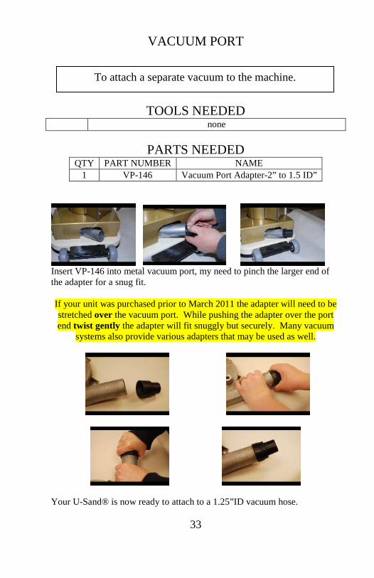
VACUUM PORT
mAY
TOOLS NEEDED none
PARTS NEEDED
QTY PART NUMBER NAME 1 VP-146 Vacuum Port Adapter-2” to 1.5 ID”
Insert VP-146 into metal vacuum port, my need to pinch the larger end of the adapter for a snug fit. If your unit was purchased prior to March 2011 the adapter will need to be stretched over the vacuum port. While pushing the adapter over the port end twist gently the adapter will fit snuggly but securely. Many vacuum
systems also provide various adapters that may be used as well.
Your U-Sand® is now ready to attach to a 1.25”ID vacuum hose.
To attach a separate vacuum to the machine.
34
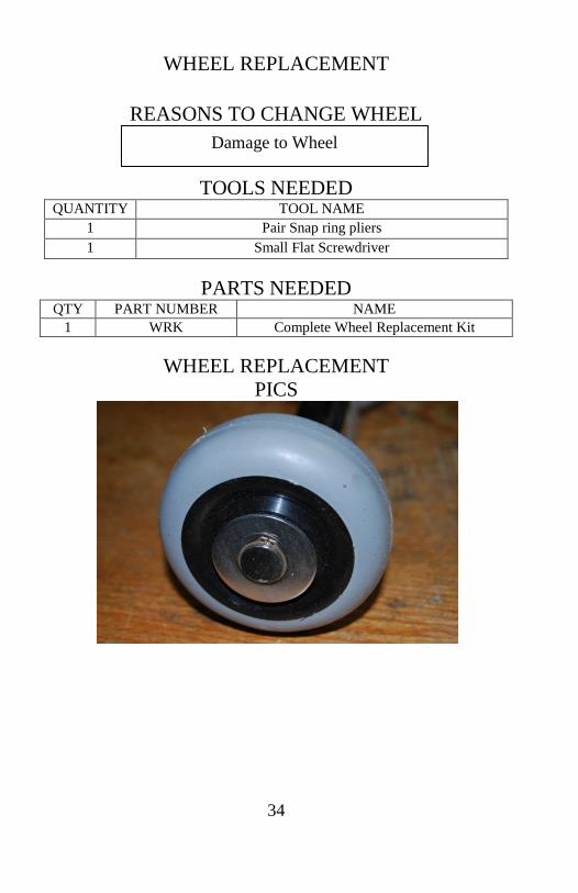
WHEEL REPLACEMENT
REASONS TO CHANGE WHEEL
TOOLS NEEDED QUANTITY TOOL NAME
1 Pair Snap ring pliers 1 Small Flat Screwdriver
PARTS NEEDED
QTY PART NUMBER NAME 1 WRK Complete Wheel Replacement Kit
WHEEL REPLACEMENT
PICS
Damage to Wheel

35
PROCEDURE MAKE SURE SWITCH IS TURNED OFF AND
MACHINE IS UNPLUGGED.
STEP PART DESCRIPTION
1 Remove snap ring, wave spring, outer washer, wheel, inner washer
2
Install WRK in the following order 1. Washer 2. Wheel 3. Washer
4. Wave Spring 5. Snap Ring be sure its completely seated
in the groove
36
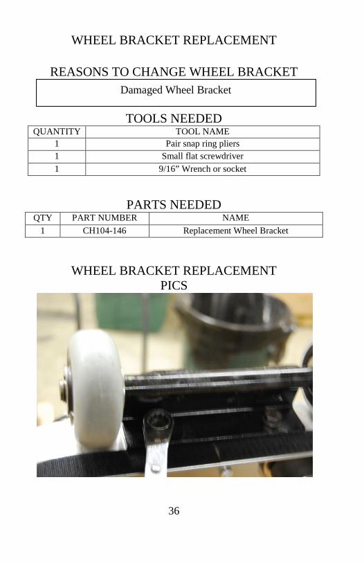
WHEEL BRACKET REPLACEMENT
REASONS TO CHANGE WHEEL BRACKET
TOOLS NEEDED QUANTITY TOOL NAME
1 Pair snap ring pliers 1 Small flat screwdriver 1 9/16” Wrench or socket
PARTS NEEDED QTY PART NUMBER NAME
1 CH104-146 Replacement Wheel Bracket
WHEEL BRACKET REPLACEMENT PICS
Damaged Wheel Bracket

37
PROCEDURE MAKE SURE SWITCH IS TURNED OFF AND
MACHINE IS UNPLUGGED.
STEP PART DESCRIPTION
1 Remove old bracket from machine
Keep bolts and washers from bracket Remove wheels from old bracket
2
Install Wheels on new bracket using the following order for each wheel
1. Washer 2. Wheel 3. Washer
4. Wave Spring 5. Snap Ring be sure its completely seated in the
groove
3 Install new bracket on machine with saved bolts and washers
38
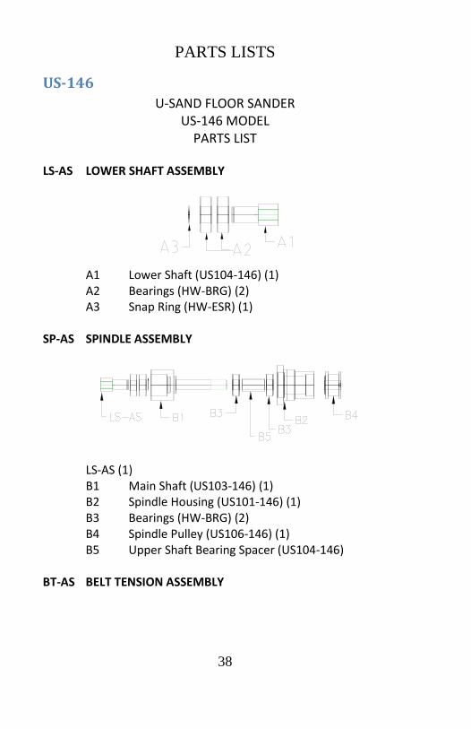
PARTS LISTS
US-146 U-SAND FLOOR SANDER
US-146 MODEL PARTS LIST
LS-AS LOWER SHAFT ASSEMBLY
A1 Lower Shaft (US104-146) (1) A2 Bearings (HW-BRG) (2) A3 Snap Ring (HW-ESR) (1) SP-AS SPINDLE ASSEMBLY
LS-AS (1) B1 Main Shaft (US103-146) (1)
B2 Spindle Housing (US101-146) (1) B3 Bearings (HW-BRG) (2) B4 Spindle Pulley (US106-146) (1) B5 Upper Shaft Bearing Spacer (US104-146)
BT-AS BELT TENSION ASSEMBLY
39
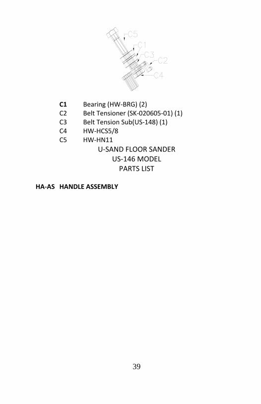
C1 Bearing (HW-BRG) (2) C2 Belt Tensioner (SK-020605-01) (1) C3 Belt Tension Sub(US-148) (1) C4 HW-HCS5/8 C5 HW-HN11
U-SAND FLOOR SANDER US-146 MODEL
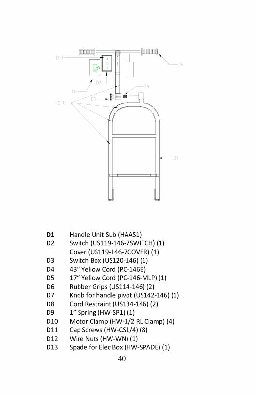
PARTS LIST HA-AS HANDLE ASSEMBLY
40
D1 Handle Unit Sub (HAAS1) D2 Switch (US119-146-7SWITCH) (1) Cover (US119-146-7COVER) (1) D3 Switch Box (US120-146) (1) D4 43” Yellow Cord (PC-146B) D5 17” Yellow Cord (PC-146-MLP) (1) D6 Rubber Grips (US114-146) (2) D7 Knob for handle pivot (US142-146) (1) D8 Cord Restraint (US134-146) (2) D9 1” Spring (HW-SP1) (1) D10 Motor Clamp (HW-1/2 RL Clamp) (4) D11 Cap Screws (HW-CS1/4) (8) D12 Wire Nuts (HW-WN) (1) D13 Spade for Elec Box (HW-SPADE) (1)
41
U-SAND FLOOR SANDER US-146 MODEL
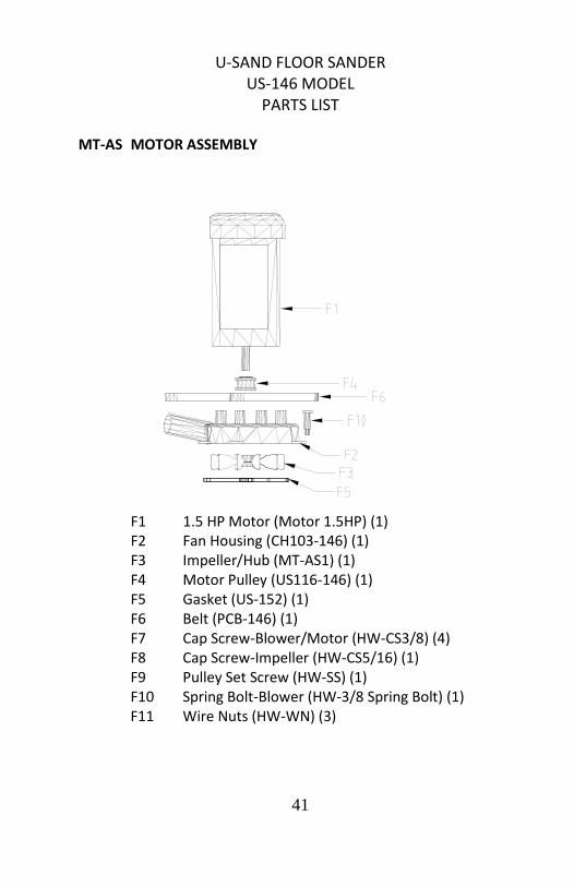
PARTS LIST MT-AS MOTOR ASSEMBLY
F1 1.5 HP Motor (Motor 1.5HP) (1) F2 Fan Housing (CH103-146) (1) F3 Impeller/Hub (MT-AS1) (1) F4 Motor Pulley (US116-146) (1) F5 Gasket (US-152) (1) F6 Belt (PCB-146) (1) F7 Cap Screw-Blower/Motor (HW-CS3/8) (4) F8 Cap Screw-Impeller (HW-CS5/16) (1) F9 Pulley Set Screw (HW-SS) (1) F10 Spring Bolt-Blower (HW-3/8 Spring Bolt) (1) F11 Wire Nuts (HW-WN) (3)
42
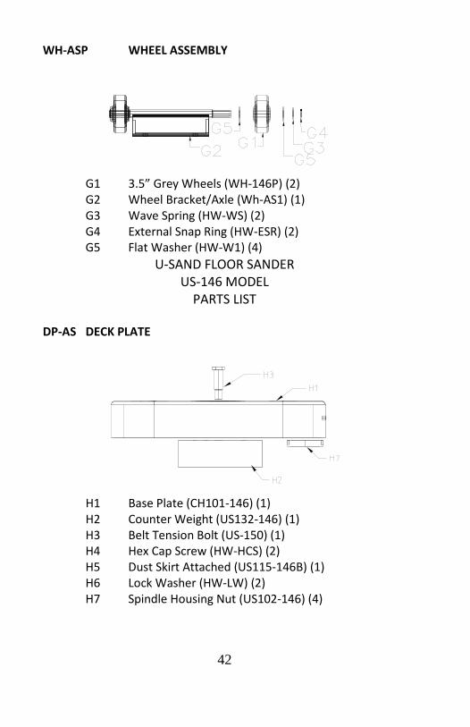
WH-ASP WHEEL ASSEMBLY
G1 3.5” Grey Wheels (WH-146P) (2) G2 Wheel Bracket/Axle (Wh-AS1) (1) G3 Wave Spring (HW-WS) (2) G4 External Snap Ring (HW-ESR) (2) G5 Flat Washer (HW-W1) (4)
U-SAND FLOOR SANDER US-146 MODEL
PARTS LIST DP-AS DECK PLATE
H1 Base Plate (CH101-146) (1) H2 Counter Weight (US132-146) (1) H3 Belt Tension Bolt (US-150) (1) H4 Hex Cap Screw (HW-HCS) (2) H5 Dust Skirt Attached (US115-146B) (1) H6 Lock Washer (HW-LW) (2) H7 Spindle Housing Nut (US102-146) (4)
43
US-146 SANDER Nuisance Tag (US-143) (1) UL Listed Tag (US-145) (1) American Flag (LABL-FLAG) (1) Rivets (HW-RVT) (10) Orange Bag Safety (US148) (1) Belt Cover (CH02-146) (1 set 2 pc) Motor Clamps Cap Screws (HW-CS1/4) (6) Flat Washer (Hw-FW/16) (6) Lock Nut-Motor (HW-CLN) (1) Cord Restraint (US134-146) (1) Flat Washer (HW-FW3/8) (4) spring (HW-SP3/4) (2) ACCESSORY ITEMS US-146
Dust Skirt (US115-146) (1) Backer Pads (BP6) (4) Manual (US-M) (1) 25’ Yellow Cord (PC-146-FLP) (1)

44
US-PRO MODEL U-SAND FLOOR SANDER
PARTS LIST US-PRO MODEL
LS-AS LOWER SHAFT ASSEMBLY
A1 Lower Shaft (US104-146) (1) A2 Bearings (HW-BRG) (2) A3 Snap Ring (HW-ESR) (1) SP-AS-C SPINDLE ASSEMBLY
LS-AS (1) B1 Main Shaft (US103-146C) (1)
B2 Spindle Housing (US101-146C) (1) B3 Bearings (HW-BRG) (1) B4 Spindle Pulley (US106-146-7) (1) B5 Upper Shaft Bearing Spacer (US105-146) B6 Bearing (HW-BRG) (1)

45
BT-AS BELT TENSION ASSEMBLY
C1 Bearing (HW-BRG) (2) C2 Belt Tensioner (SK-020605-01) (1) C3 Belt Tension Sub(US-148) (1) C4 HW-HCS5/8 C5 HW-HN11

46
U-SAND FLOOR SANDER PARTS LIST
US-PRO MODEL HA-AS-C HANDLE ASSEMBLY
D1 Handle Unit Sub (HAAS1C) D2 Switch (US119-146-7SWITCH) (1) Cover (US119-146-7COVER) (1) D3 Switch Box (US120-146-7) (1) D4 43” Grey Cord (PC-146C) D5 17” Grey Cord (PC-146-MLPC) (1) D6 Rubber Grips (US114-146) (2) D7 Knob for handle pivot (US142-146) (1) D8 Cord Restraint (US134-146) (2) D9 1” Spring (HW-SP1) (1) D10 Motor Clamp (HW-1/2 RL Clamp) (4) D11 Cap Screws (HW-CS1/4) (8) D12 Wire Nuts (HW-WN) (1) D13 Spade for Electric Box (HW-SPADE) (1)
47
U-SAND FLOOR SANDER PARTS LIST
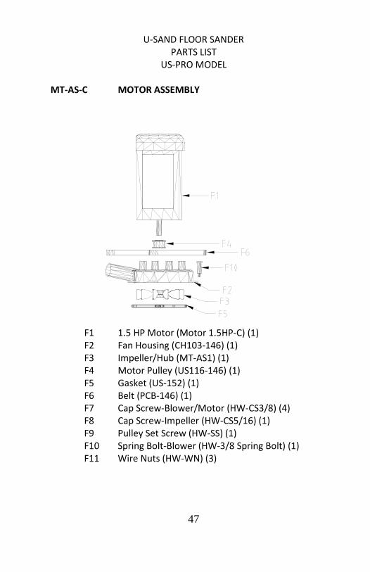
US-PRO MODEL MT-AS-C MOTOR ASSEMBLY
F1 1.5 HP Motor (Motor 1.5HP-C) (1) F2 Fan Housing (CH103-146) (1) F3 Impeller/Hub (MT-AS1) (1) F4 Motor Pulley (US116-146) (1) F5 Gasket (US-152) (1) F6 Belt (PCB-146) (1) F7 Cap Screw-Blower/Motor (HW-CS3/8) (4) F8 Cap Screw-Impeller (HW-CS5/16) (1) F9 Pulley Set Screw (HW-SS) (1) F10 Spring Bolt-Blower (HW-3/8 Spring Bolt) (1) F11 Wire Nuts (HW-WN) (3)

48
WH-ASP WHEEL ASSEMBLY
G1 3.5” Grey Wheels (WH-146P) (2) G2 Wheel Bracket/Axle (Wh-AS1) (1) G3 Wave Spring (HW-WS) (2) G4 External Snap Ring (HW-ESR) (2) G5 Flat Washer (HW-W1) (4)
49
U-SAND FLOOR SANDER PARTS LIST
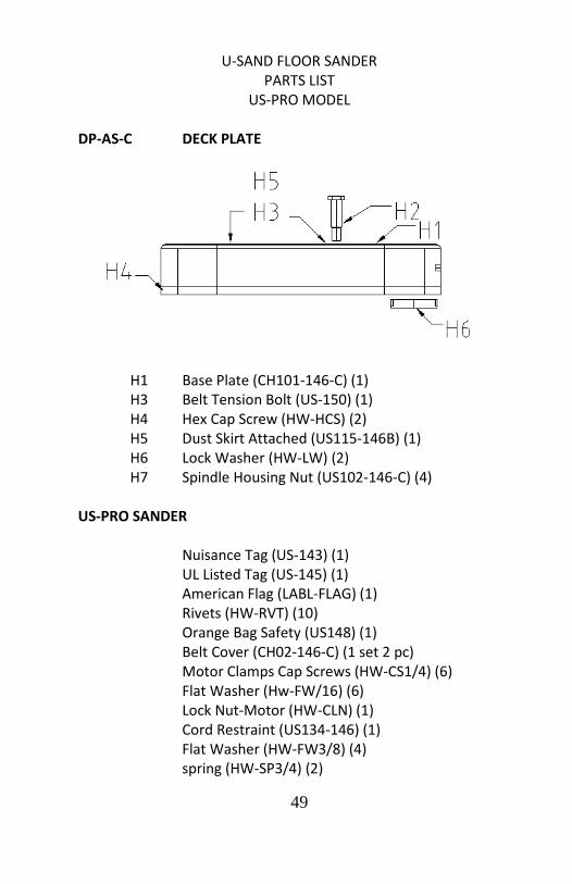
US-PRO MODEL DP-AS-C DECK PLATE
H1 Base Plate (CH101-146-C) (1) H3 Belt Tension Bolt (US-150) (1) H4 Hex Cap Screw (HW-HCS) (2) H5 Dust Skirt Attached (US115-146B) (1) H6 Lock Washer (HW-LW) (2) H7 Spindle Housing Nut (US102-146-C) (4) US-PRO SANDER Nuisance Tag (US-143) (1) UL Listed Tag (US-145) (1) American Flag (LABL-FLAG) (1) Rivets (HW-RVT) (10) Orange Bag Safety (US148) (1) Belt Cover (CH02-146-C) (1 set 2 pc) Motor Clamps Cap Screws (HW-CS1/4) (6) Flat Washer (Hw-FW/16) (6) Lock Nut-Motor (HW-CLN) (1) Cord Restraint (US134-146) (1) Flat Washer (HW-FW3/8) (4) spring (HW-SP3/4) (2)

50
ACCESSORY ITEMS US-PRO
Dust Skirt (US115-146) (1) Backer Pads (BP6) (4) Manual (US-MP) (1) 25’ Grey Cord (PC-146-FLPC) (1)
51
BT700 MODEL U-SAND FLOOR SANDER
BT700 MODEL PARTS LIST
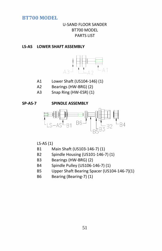
LS-AS LOWER SHAFT ASSEMBLY
A1 Lower Shaft (US104-146) (1) A2 Bearings (HW-BRG) (2) A3 Snap Ring (HW-ESR) (1) SP-AS-7 SPINDLE ASSEMBLY
LS-AS (1) B1 Main Shaft (US103-146-7) (1)
B2 Spindle Housing (US101-146-7) (1) B3 Bearings (HW-BRG) (2) B4 Spindle Pulley (US106-146-7) (1) B5 Upper Shaft Bearing Spacer (US104-146-7)(1) B6 Bearing (Bearing-7) (1)
52
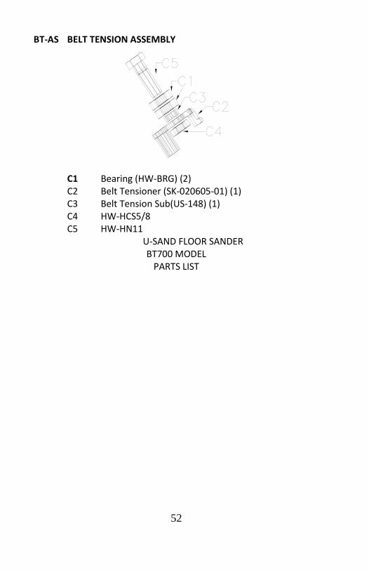
BT-AS BELT TENSION ASSEMBLY
C1 Bearing (HW-BRG) (2) C2 Belt Tensioner (SK-020605-01) (1) C3 Belt Tension Sub(US-148) (1) C4 HW-HCS5/8 C5 HW-HN11
U-SAND FLOOR SANDER BT700 MODEL
PARTS LIST

53
HA-AS-7 HANDLE ASSEMBLY
D1 Handle Unit Sub (HAASY) D2 Switch (US119-146-7SWITCH) (1) Cover (US119-146-7COVER) (1) D3 Switch Box (US120-146) (1) D4 43” Yellow Cord (PC-146B-7)(1) D5 17” Yellow Cord (PC-146S-7) (1) D6 Rubber Grips (US114-146) (2) D7 Knob for handle pivot (US142-146) (1) D8 Cord Restraint (US134-146) (2) D9 1” Spring (HW-SP1) (1) D10 Motor Clamp (HW-1/2 RL Clamp) (4) D11 Cap Screws (HW-CS1/4) (8) D12 Wire Nuts (HW-WN) (1) D13 Spade for Elec Box (HW-SPADE) (1)

54
U-SAND FLOOR SANDER BT700 MODEL
PARTS LIST MT-AS-7 MOTOR ASSEMBLY
F1 Motor 3HP (Motor 3HP) (1) F2 Fan Housing (CH103-146) (1) F3 Impeller/Hub (MT-AS1) (1) F4 Motor Pulley (US116-146-7) (1) F5 Gasket (US-152) (1) F6 Belt (PCB-146) (1) F7 Cap Screw-Blower/Motor (HW-CS3/8) (4) F8 Cap Screw-Impeller (HW-CS5/16) (1) F9 Pulley Set Screw (HW-SS) (1) F10 Spring Bolt-Blower (HW-3/8 Spring Bolt) (1) F11 Wire Nuts (HW-WN) (3)
55
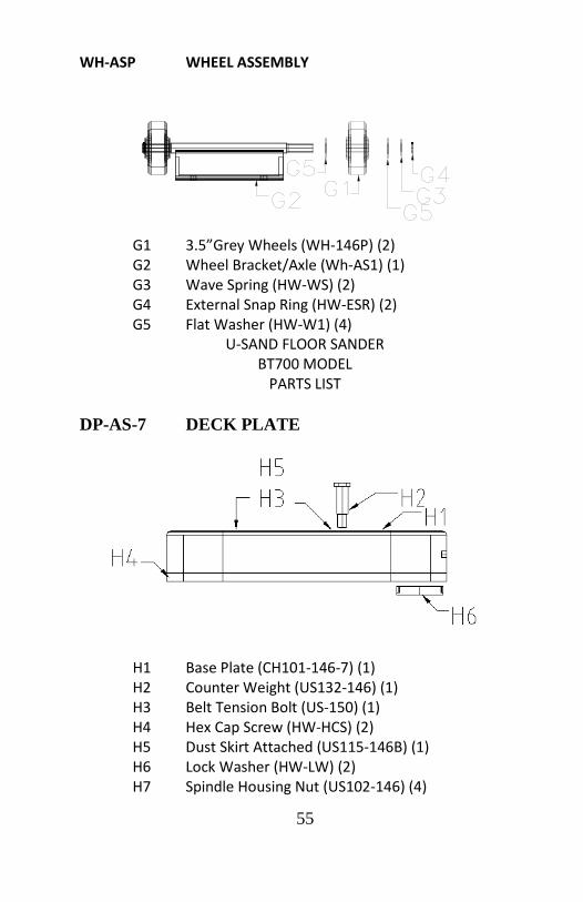
WH-ASP WHEEL ASSEMBLY
G1 3.5”Grey Wheels (WH-146P) (2) G2 Wheel Bracket/Axle (Wh-AS1) (1) G3 Wave Spring (HW-WS) (2) G4 External Snap Ring (HW-ESR) (2) G5 Flat Washer (HW-W1) (4)
U-SAND FLOOR SANDER BT700 MODEL
PARTS LIST DP-AS-7 DECK PLATE
H1 Base Plate (CH101-146-7) (1) H2 Counter Weight (US132-146) (1) H3 Belt Tension Bolt (US-150) (1) H4 Hex Cap Screw (HW-HCS) (2) H5 Dust Skirt Attached (US115-146B) (1) H6 Lock Washer (HW-LW) (2) H7 Spindle Housing Nut (US102-146) (4)
56
BT700 SANDER Nuisance Tag (US-143) (1) American Flag (LABL-FLAG) (1) Rivets (HW-RVT) (10) Orange Bag Safety (US148) (1) Belt Cover (CH02-146-7) (1 set 2 pc) Motor Clamps Cap Screws (HW-CS1/4) (6) Flat Washer (Hw-FW/16) (6) Lock Nut-Motor (HW-CLN) (1) Cord Restraint (US134-146) (1) Flat Washer (HW-FW3/8) (4) spring (HW-SP3/4) (2) ACCESSORY ITEMS BT700
Dust Skirt (US115-146) (1) Backer Pads (BP6) (4) Manual (US-M) (1) 50’ Yellow Cord (PC-146-FLP-7) (1)