Embed Size (px)
Citation preview
Naval Research LaboratoryWashington, DC 20375-5320
NRL/MR/5760--17-9727
(U) U.S. Naval Research LaboratoryFinal Analysis Report to NATO Above Water Warfare Capabilities Group2016 Naval Electromagnetic Operations Trials
May 23, 2017
Approved for public release; distribution is unlimited.
Anthony J. AllegrezzA
Advanced Techniques Branch Tactical Electronic Warfare Division
UNCLASSIFIED
UNCLASSIFIED

i
REPORT DOCUMENTATION PAGE Form ApprovedOMB No. 0704-0188
3. DATES COVERED (From - To)
Standard Form 298 (Rev. 8-98)Prescribed by ANSI Std. Z39.18
Public reporting burden for this collection of information is estimated to average 1 hour per response, including the time for reviewing instructions, searching existing data sources, gathering and maintaining the data needed, and completing and reviewing this collection of information. Send comments regarding this burden estimate or any other aspect of this collection of information, including suggestions for reducing this burden to Department of Defense, Washington Headquarters Services, Directorate for Information Operations and Reports (0704-0188), 1215 Jefferson Davis Highway, Suite 1204, Arlington, VA 22202-4302. Respondents should be aware that notwithstanding any other provision of law, no person shall be subject to any penalty for failing to comply with a collection of information if it does not display a currently valid OMB control number. PLEASE DO NOT RETURN YOUR FORM TO THE ABOVE ADDRESS.
5a. CONTRACT NUMBER
5b. GRANT NUMBER
5c. PROGRAM ELEMENT NUMBER
5d. PROJECT NUMBER
5e. TASK NUMBER
5f. WORK UNIT NUMBER
2. REPORT TYPE1. REPORT DATE (DD-MM-YYYY)
4. TITLE AND SUBTITLE
6. AUTHOR(S)
8. PERFORMING ORGANIZATION REPORT NUMBER
7. PERFORMING ORGANIZATION NAME(S) AND ADDRESS(ES)
10. SPONSOR / MONITOR’S ACRONYM(S)9. SPONSORING / MONITORING AGENCY NAME(S) AND ADDRESS(ES)
11. SPONSOR / MONITOR’S REPORT NUMBER(S)
12. DISTRIBUTION / AVAILABILITY STATEMENT
13. SUPPLEMENTARY NOTES
14. ABSTRACT
15. SUBJECT TERMS
16. SECURITY CLASSIFICATION OF:
a. REPORT
19a. NAME OF RESPONSIBLE PERSON
19b. TELEPHONE NUMBER (include areacode)
b. ABSTRACT c. THIS PAGE
18. NUMBEROF PAGES
17. LIMITATIONOF ABSTRACT
(U) U.S. Naval Research Laboratory Final Analysis Report toNATO Above Water Warfare Capabilities Group2016 Naval Electromagnetic Operations Trials
Anthony J. Allegrezza
Naval Research Laboratory4555 Overlook Avenue, SWWashington, DC 20375-5339
NRL/MR/5760--17-9727
OPNAV N2/N6 F321
Approved for public release. Distribution unlimited.
NOTE: Specific distribution to meet reporting requirements: 1) OPNAV N2/N6 F321 - PDF 2) Norwegian Navy NEMO 2016 TrialDirector - PDF & Word Document (with supporting graphics files)
UnclassifiedUnlimited
SAR 34
Carlos Maraviglia
(202) 404-7686
23-05-2017 Memorandum Report
Tactical Electronic Warfare Division (TEWD)Naval Electro Magnetic Operation (NEMO)Electro-optical (EO)
Imaging infrared (IIR)Radio frequency (RF)Stimulator
Simulator
06 June 2016 – 15 June 2016
Office of the Chief of Naval OperationsAttn: OPNAV N2/N6 F3212000 Navy PentagonWashington, D.C. 20350-2000
UnclassifiedUnlimited
UnclassifiedUnlimited
(U) During the week of 06 June 2016, the Tactical Electronic Warfare Division (TEWD) of the US Naval Research Laboratory (NRL) participated in the NATO Naval Electro Magnetic Operation (NEMO) 2016 Trials. Assets consisted of two flyable and one shore-based optical seeker simulators and one shore based RF stimulator. This report addresses NRL Code 5752’s fielded Electro-Optical (EO) and Imaging Infrared (IIR) Seeker Simulation Systems and the NRL Code 5763 Radio Frequency (RF) Stimulator. It includes and covers system descriptions, setup, data collection, and test goals that were accomplished.

UNCLASSIFIED
ii UNCLASSIFIED
This Page Intentionally Left Blank

UNCLASSIFIED
iii UNCLASSIFIED
Table of Contents
Table of Contents .......................................................................................................................... iii
List of Tables .......................................................................................................................... iv
List of Figures .......................................................................................................................... iv
List of Appendices ......................................................................................................................... iv
EXECUTIVE SUMMARY ......................................................................................................... E-1
1. Introduction ........................................................................................................................... 1
2. US NEMO Objectives................................................................................................................. 3
2.1. EO/IIR Objectives ................................................................................................................ 3
2.2. RF Objectives....................................................................................................................... 3
3. Test Sites, Assets & Setup .......................................................................................................... 4
3.1. Shore Sites ........................................................................................................................... 4
3.2. Lear jet Systems ................................................................................................................... 6
4. Test Asset Descriptions............................................................................................................... 7
4.1. Description of FOXTROT Anti-ship Missile (ASM) Simulator ......................................... 7
4.2. Description of IOTA-MIKE Unmanned Aircraft System (UAS) Simulator ....................... 7
4.3. Description of CAWS .......................................................................................................... 8
4.4. Norwegian DA-20 ................................................................................................................ 9
5. Test Planning ........................................................................................................................... 9
5.1. Test Serial Descriptions ....................................................................................................... 9
5.2. Flight Test Planning ........................................................................................................... 11
5.3. Shore Test Planning ........................................................................................................... 13
6. Data Collected & Test Results .................................................................................................. 14
6.1. Lear Flight Test Results ..................................................................................................... 14
6.2. FOXTROT Portable (Shore) Test Results ......................................................................... 14
6.3. ROSY Decoy Demonstration ............................................................................................. 14
6.4. IOTA-MIKE ...................................................................................................................... 17
6.5. Decoy Runs ........................................................................................................................ 17
6.6. CAWS Ground ................................................................................................................... 17
7. NRL Summary ......................................................................................................................... 18

UNCLASSIFIED
iv UNCLASSIFIED
List of Tables
Table 1 EO/IIR Simulator Sensors ................................................................................................. 8 Table 2 Complex Arbitrary Waveform Synthesizer (CAWS) Specifications ................................ 9 Table 3 US Trials Objectives from the NOL ................................................................................ 10 Table 4 Test Range Op Areas ....................................................................................................... 11 Table 5 Planned Lear Sortie Schedule .......................................................................................... 12 Table 6 Actual Lear Sortie Schedule ............................................................................................ 12 Table 7 ASMD Serial Descriptions .............................................................................................. 13 Table 8 ROSY Run Information - 09 Jun 2016 ............................................................................ 16 Table 9 Post-processing results of ROSY Decoys ........................................................................ 16 Table 10 CAWS Waveforms ........................................................................................................ 18
List of Figures
Figure 1 Map of Norway................................................................................................................. 1 Figure 2 Andenes and Andøya Air Station ..................................................................................... 2 Figure 3 Shore Test Site Locations ................................................................................................. 4 Figure 4 FOXTROT Portable Shore Configuration........................................................................ 5 Figure 5 CAWS Shore Site Configuration...................................................................................... 5 Figure 6 Lear jet .............................................................................................................................. 6 Figure 7 IOTA MIKE Pod .............................................................................................................. 6 Figure 8 FOXTROT Pod ................................................................................................................ 6 Figure 9 NEMO Trials Op Areas .................................................................................................. 11 Figure 10 ROSY Installation Locations ........................................................................................ 15
Figure 11 ROSY Installation on HNoMS Mjølner ....................................................................... 15
List of Appendices
Appendix 1 EO/IIR Simulator Configuration Appendix 2 Summary of Lear FOXTROT Runs Appendix 3 Summary of Lear IOTA-MIKE Runs
Appendix 4 Summary of FOXTROT Portable (Shore) Runs Appendix 5 Summary of CAWS Runs Appendix 6 Results of ROSY Demo Runs
Appendix 7 Acronyms

UNCLASSIFIED
E-1 UNCLASSIFIED
EXECUTIVE SUMMARY
NATO Above Water Warfare Capabilities Group (AWWCG) has set out a program of annual Trials, approved by the NATO Naval Armaments Group (NNAG), to evaluate the effectiveness of techniques and tactics needed to establish interoperability, and to examine and reduce the potential for blue on blue engagements between member nations.
The annual program called Naval Electro Magnetic Operation (NEMO), were held from 06-10 June 2016 off Andenes/Andøya, Norway. Host for the Trials was Norway, with the United States as the co-host.
The Trials provide the opportunity to:
Improve interoperability
Collect scientific data for member nations and NATO STO groups
Test procedures, tactics and equipment
Utilize data from other countries’ test equipment and ASCM Simulators/Stimulators
Conduct Joint Electronic Warfare training
Develop improved, and cooperative, platform protection based on Trials results The Trials were designed from the NEMO Objectives List (NOL) as published by the System Concept and Integration Group (SCI-293) of the AWWCG. The NOL provides both broad and detailed objectives for evaluation of all aspects of Electronic Warfare related testing. Test specific objectives were derived from national requests and from available participating assets.

UNCLASSIFIED
E-2 UNCLASSIFIED
This Page Intentionally Left Blank

UNCLASSIFIED
Page 1 of 18
UNCLASSIFIED
1. Introduction
The Naval Research Laboratory (NRL), Tactical Electronic Warfare Division (TEWD) participated in the NATO Above Water Warfare Capabilities Group (AWWCG), 2016 Naval Electromagnetic Operations (NEMO) Trials. The Trials were hosted by Norway, with the United States as the co-host.
The Trials were conducted in the area of Andøya, Norway (reference Figure 1). The Norwegian Air Force, 133 Air Wing based at Andøya Air Station, was the host location for the Trials. Facilities and test support were provided by Andøya Air Station, the Andøya Space Launch Center, the Norwegian Navy Operational Logistics Unit (MARCSS), and associated Surface and Air Operations Areas.
Andøya Air Station is located in Andenes, on the northern end of the island of Andøya, in Northern Norway approximately 200 miles north of the Arctic Circle (reference Figure 2). This area provided a protected fjord (Andfjorden) on the east and open ocean on the north and west. The Air Station provided ground sites to support numerous test and measurement stations, airfield, and aircraft support.
NRL provided a Lear jet with captive-carry imaging infrared (IIR) and Electro-Optical (EO) Simulators, and at ground sites located on the Air Station, an IIR Simulator and Radio Frequency (RF) Stimulator.
Figure 1 Map of Norway ________________Manuscript approved February 28, 2017.

UNCLASSIFIED
Page 2 of 18
UNCLASSIFIED
Figure 2 Andenes and Andøya Air Station
The following ships participated in the 2016 NEMO Trials:
HDMS Niels Juel (F-363) – Denmark
BNS Leopold I (F-930) – Belgium
HNLMS De Ruyter (F-804) – Netherlands
SPS Blas de Lezo (F-103) – Spain
FS Aquitaine (D-650) – France
TCG Barbaros (F-224) – Turkey
HNoMS Roald Amundsen (F-311) – Norway
HNoMS Storm (P-961) – Norway
HNoMS Steil (P-963) – Norway
HNoMS Mjølner (HS-5) – Norway (used only for ROSY testing)
The following countries provided shore assets:
Germany Norway USA France Turkey NATO (JEWCS)
Denmark Great Britain Netherlands

UNCLASSIFIED
Page 3 of 18
UNCLASSIFIED
The following countries provided air assets:
USA – Lear jet
Norway – DA-20 jet, PICO-SAR Helo, P3-C, UAV
Germany – TERRASAR Satellite
2. US NEMO Objectives
2.1. EO/IIR Objectives
Collect EO/IIR imagery of various platforms
Evaluate the effectiveness of decoys and deployment tactics against imaging infrared (IIR) seekers
Evaluate ship detection based on signature measurements.
2.2. RF Objectives
Create a multi-threat environment using the CAWS Radar Stimulator in conjunction with German ASCM Simulator.

UNCLASSIFIED
Page 4 of 18
UNCLASSIFIED
3. Test Sites, Assets & Setup
3.1. Shore Sites
EO/IIR and RF test and measurement sites were set up on the eastern shore side of the Air Station. FOXTROT Portable and CAWS were housed in host provided CONEX type shelters. Figure 3 shows the locations of the FOXTROT Portable and CAWS systems shore sites.
FOXTROT Portable 69° 17.178’ N, 016° 10.299’ E
o Shore Site Equipment Configuration shown in Figure 4
CAWS was located at 69° 17.037’ N, 016° 10.590’ E
o Shore Site Equipment Configuration shown in Figure 5
Figure 3 Shore Test Site Locations

UNCLASSIFIED
Page 5 of 18
UNCLASSIFIED
Figure 4 FOXTROT Portable Shore Configuration
Figure 5 CAWS Shore Site Configuration

UNCLASSIFIED
Page 6 of 18
UNCLASSIFIED
3.2. Lear jet Systems
Lear jet (Figure 6) was configured with flight-ready versions built in Standard Instrumentation Pod (SIP), and deployed as a captive-carry simulator under the wing. FOXTROT flyable simulator (Figure 8) is a programmable, man-in-the-loop, real-time image tracking systems designed to simulate imaging infrared (IIR) and Electro-Optical (EO) Television (TV) missile threats. The systems are research tools intended to represent both modern and future classes of threats with imaging front-ends, and sophisticated image processing capabilities. Two configurations of flyable payloads were deployed: IOTA-MIKE (Figure 7) an EO TV visible band seeker, and FOXTROT, a mid-wave IIR band seeker simulator. The air crew consisted of a pilot, copilot, the FOXTROT operator, the IOTA-MIKE operator.
Figure 6 Lear jet
Figure 8 FOXTROT Pod Figure 7 IOTA MIKE Pod

UNCLASSIFIED
Page 7 of 18
UNCLASSIFIED
4. Test Asset Descriptions
4.1. Description of FOXTROT Anti-ship Missile (ASM) Simulator
FOXTROT is a simulator for an IIR ASM, composed of off-the-shelf, commercially available components. Configuration and general specifications as shown in Table 1, detailed specifications as shown in Appendix 1. This simulator is maintained under the US Navy’s Effectiveness of Naval Electronic Warfare Systems (ENEWS) program. Control and integration software was developed by NRL’s Tactical Electronic Warfare Division. Two versions of the simulator were fielded:
Flyable – housed in a Standard Instrument Pod (SIP) for captive-carry under the wing of the Lear jet.
Portable – packaged in lightweight containers and located in a shelter at the ground operations IR Test Site.
The FOXTROT simulator is a programmable, man-in-the-loop, real-time image tracking system designed to simulate imaging infrared (IIR) missile threats. The system was developed as a research tool with the ability to represent both modern and future classes of threats, with an imaging front end and sophisticated image processing capabilities. Video data from an imager can be processed in real time or saved as raw video data that can be post-processed for target track evaluation and algorithm development.
The FOXTROT simulators consists of several major sub-system components: commercially available infrared imager, wide field-of-view reference TV camera (visible band), video image processing and analysis computer, gyro-stabilized gimbal with an electronic control loop, data recording devices, and standard PC for I/O control. The infrared imager and the reference camera are installed on the same gimbal.
Both FOXTROT simulators (flyable and portable) were based on a "NightConqueror II - 256" IIR camera from Cincinnati Electronics as the primary tracker. The NightConqueror is a ruggedized, staring focal plane array based, mid-wave infrared camera.
FOXTROT simulators also utilize a visual reference camera. The flyable system contains a Cohu Closed Circuit Television (CCD), wide field-of-view visible TV camera. The FOXTROT portable system uses a Photon Focus, 14-bit monochrome visible camera.
FOXTROT relies on manual acquisition, by an experienced operator to select the target of interest, after which the target is auto-tracked. The tracking algorithm is based on a binary threshold, centroid track. The digital image is passed into the video processing PC which determines a target pixel value threshold based on imagery inside several gates. Outer clutter gates adjust the threshold based upon the amount of clutter in the scene/image. A background gate and track gate then determines the final threshold based upon the image within their gates and clutter data from the clutter gates. The result is a binary color image of the target. This image is centroided and new track gate dimensions are calculated for the next image. The resulting data is then passed back to the gimbal to maintain pointing accuracy.
4.2. Description of IOTA-MIKE Unmanned Aircraft System (UAS) Simulator
IOTA-MIKE Standard Instrument Pod (SIP) Anti-ship Missile Simulator – The IOTA-MIKE system is a programmable simulator of a visible band optical UAS payload comprised all off-

UNCLASSIFIED
Page 8 of 18
UNCLASSIFIED
the-shelf, commercially available components. Configuration and general specifications as shown in Table 1, detailed specifications as shown in Appendix 1. The software is written and maintained by NRL’s Tactical Electronic Warfare Division and the software load used for the NEMO 2016 Trials is unclassified. This system is housed in a SIP that was slightly modified to accommodate its gimbal and mounted to the wing of the Lear jet for flight.
The IOTA-MIKE simulator consists of several major sub-system components: commercially available CCD NTSC camera (visible band) imager, laptop computer for system control, gyro-stabilized gimbal with an electronic control loop, data recording devices, and an on board PC/104 embedded computer for I/O control.
IOTA-MIKE relies on an experienced operator to determine the target of interest. The tracking algorithm is based on a binary threshold, centroid track. The digital image is passed into the video processing PC which determines a target pixel value threshold based on imagery inside several gates. Outer clutter gates adjust the threshold based upon the amount of clutter in the scene/image. A background gate and track gate then determines the final threshold based upon the image within their gates and clutter data from the clutter gates. The result is a binary color image of the target. This image is centroided and new track gate dimensions are calculated for the next image. The resulting data is then passed back to the gimbal to maintain pointing accuracy.
UNCLASSIFIED
System Name Spectral Band
(µm) Detector Type
FOV
(Wide/Narrow) Gimbal Limits Tracker
FOXTROT Portable SIM
- CE Night Conqueror Mid-Wave IIR
InSb (256 x 256)
7°x7°/-3°x3° Az ±20°
El +2.5° to -10° Man-In-Loop
- Photon Focus Visible Camera
Monochrome 14-bit Visible
CMOS (1312 x 1082)
FOXTROT Flyable SIM
- CE Night Conqueror Mid-Wave IIR
InSb (256 x 256) 7°x7°/-3°x3°
Az ±20° El +2.5° to -10°
Man-In-Loop - Cohu TV Color Visible CCD NTSC IOTA-MIKE Flyable SIM
- Cohu CCD Camera
Color Visible CCD NTSC 6°x6°
Az ±20° El +2.5° to -10°
Man-In-Loop
UNCLASSIFIED
Table 1 EO/IIR Simulator Sensors
4.3. Description of CAWS
The Complex Arbitrary Waveform Synthesizer (CAWS) is a programmable radar stimulator (transmit only) that was developed and built by the Naval Research Laboratory. CAWS is capable of reproducing simple to complex waveforms in the I and J bands from a single device. Table 2 provides the overall system capabilities for the CAWS Stimulator. Each waveform parameter can be individually programmed to provide accurate signals for laboratory and operational testing. CAWS can be packaged in both portable (configuration used for NEMO

UNCLASSIFIED
Page 9 of 18
UNCLASSIFIED
2016), and captive carry flyable configurations. CAWS requires connection to an external RF amplifier and antenna. Amplifiers can vary in size to match the individual test requirements. The operational concept of CAWS is similar to JEWCS ALQ-167 Stimulation Pods.
UNCLASSIFIED
Complex Arbitrary Waveform Synthesizer (CAWS) Specifications Frequency 8 – 18 GHz (I & J Band) PRF Programmable Pulse Modulation Programmable Pulse Width Programmable Antenna Fixed Horn Polarization Vertical Scan Programmable Attenuator Simulation ERP 40 dBw Data Products Electronic On/Off Log Files
Operator Notes UNCLASSIFIED
Table 2 Complex Arbitrary Waveform Synthesizer (CAWS) Specifications
4.4. Norwegian DA-20
The Royal Norwegian Air Force operates a small fleet of Falcon DA20ECM aircraft in the electronic warfare role. Built in France as the Dassault Falcon 200 and originally designed as a business jet. The aircraft was modified to undertake maritime surveillance, electronic warfare and other roles.
5. Test Planning
5.1. Test Serial Descriptions
SCI-293 is a Task Group under the NATO Science and Technology Organization (STO), Systems, Concepts and Integration (SCI) Panel that is responsible for providing scientific support for the NEMO Trials, maintaining continuity in those trial activities from year to year.
To support this continuity, SCI-293 has developed the NEMO Objectives List (NOL) that describes the objectives that are applicable to the Electronic Warfare Community. These objectives encompass signature measurements, decoy/electronic warfare evaluation and tactics, ASCM seeker simulators and stimulators, GPS and communications jamming, radar/infrared/electro-optical threats and evaluation, and experimental concepts/equipment from participating nations and industry.
The goals and conduct of the Trials are dependent on the participation of National assets, and industry. These assets include ships, aircraft, and shore-based equipment. Test Serial Descriptions are developed from known participating assets and the individual objectives that apply form the NOL.
Table 3 outlines the NOL objectives that the US proposed to accomplish with the provided US assets.

UNCLASSIFIED
Page 10 of 18
UNCLASSIFIED
UNCLASSIFIED
Objective Description Lear Shore DA-20
FOXTROT IOTA-
MIKE
FOXTROT CAWS EW
D2 Flare Performance X X X R1 RESM against simple
waveforms X
R3 ESM performance in cluttered, congested, special environments, and situations
X X
R6 Missile and projectile approach warning sensors
X X
S1 Signatures - IR X X X S1.1 Steady state IR signature X X S1.2 IR signature at different
distances and at long distance X X
S1.3 Dynamic IR signature X X S1.5 IR signature of exhaust gas X X S3.2 Monitoring and influencing
passive signatures X X
U1 Radar/ Comms Jamming X U4 IR (including IIR) seeker tactics
(decoys, IR jamming, and/or combinations)
X X
U4.1 IR decoying on IR seeker X X U4.3 IR (including IIR) seeker tactics
(decoys, IR jamming and or combinations)
X X
U4.4 Command Line-Of-Sight (CLOS; including Active/Laser) seeker tactics (decoys, jamming and or combinations)
X X X
U6 EO (TV/IR) seeker tactics (decoys, jamming and/or combinations)
X X
U7 Hybrid/multi-mode RF/IR/IIR/ARM seeker tactics (decoys, RF/IR/IIR jamming and/or combinations)
X X
X Experimental (industry/demonstration)
X X
UNCLASSIFIED Table 3 US Trials Objectives from the NOL
The Andøya Test Range was subdivided into smaller OpAreas that provided regions for specific testing requirements. Figure 9 depicts the layout of the Test Range Op Areas; areas used by US are described in Table 4.

UNCLASSIFIED
Page 11 of 18
UNCLASSIFIED
Figure 9 NEMO Trials Op Areas
UNCLASSIFIED OpArea Designated Use
AIR-SEA 2 (Sienna) Northern Open Water testing with Surface and Air assets. Flight area for Lear
LAND-AIR (Black) Open Water testing with Surface and Air assets, directly west of Fjord entrance. Flight area for Lear
IIR Measurement (Green)
Test and measurement of Surface assets by IIR equipment from shore sites (FOXTROT Portable)
RF Seeker (Blue) Test area for RF Seekers from shore sites (CAWS location) UNCLASSIFIED
Table 4 Test Range Op Areas
5.2. Flight Test Planning
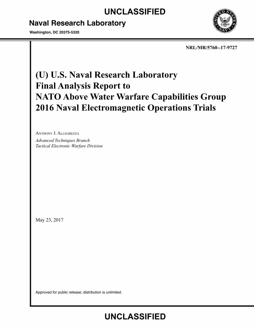
Lear jet testing was scheduled for 18 flight hours during the Trials. Due to poor weather conditions the Monday afternoon sortie was terminated early and flights for Tuesday (AM and PM sorties) and Wednesday morning were cancelled. Back-up sortie time was utilized to obtain a total of 13 flight hours of testing. Planned flights for Trials are as shown in Table 5, Actual Schedule is shown in Table 6. Note – All times are Local (BRAVO) Time, UTC +2:00.
UNCLASSIFIED
UNCLASSIFIED
UNCLASSIFIED
Page 12 of 18
UNCLASSIFIED
UNCLASSIFIED
Planned Lear Sortie Schedule Mon
06 Jun
Tue
07 Jun
Wed
08 Jun
Thu
09 Jun
Fri
10 Jun
No Fly 0800-1030 0800-1030 0800-1030 Back-Up 1330-1600 1330-1600 1330-1600 Back-Up -----
UNCLASSIFIED Table 5 Planned Lear Sortie Schedule
UNCLASSIFIED
Actual Lear Sortie Schedule Mon
06 Jun
Tue
07 Jun
Wed
08 Jun
Thu
09 Jun
Fri
10 Jun
No Fly No Flight Ops
Due To Weather
No Flight Ops Due To Weather 0843-1142 0808-1054
1745-1842 Return Early
Due To Weather 1605-1730 1522-1720 1245-1422
UNCLASSIFIED Table 6 Actual Lear Sortie Schedule
Test Serials were developed for Lear operations that would employ the captive carry aircraft simulator systems against the units available in the assigned Op Areas. Sixteen individual Serial Descriptions were developed. The Serials were identified as “ASMD” (Anti-Ship Missile Defense) and are summarized in Table 7.
Serials ASMD 01 through 07 supported flight operations in the AIR-SEA (Sienna) Op Area, ASMD 08 through 14 are the same, with the exception of specifying the LAND-SEA (Black) Op Area. ASMD 15 and 16 encompassed the decoy test firing for ROSY. ROSY is a demonstration decoy from Rhienmettal. Open water firings of ROSY were conducted in the LAND-AIR (Black) Op Area under Serial ASMD-15. ASMD 16 governed the runs firings ROSY inside the Fjord, in the IR Measurement (Green) Area.
All EO/IIR engagements against ships were conducted in the Air-Sea 2 (Sienna) and Land Air (Black) Op Areas. The Lear flew patterns around the Op Areas to engage single or multiple units as required. Serials were written from the NEMO Objectives List (NOL) and requirements from individual Nations. Due to limitations for Norwegian airspace, the Lear was limited to a minimum altitude of 300 feet. These Serials and the associated objectives from the NOL are described in Table 7.

UNCLASSIFIED
Page 13 of 18
UNCLASSIFIED
UNCLASSIFIED
Serial ID Serial Description NEMO OpArea Objectives
ASMD 01 Calibration Run – 300 FT LEAR EO/IR CALIBRATION RUN
Air-Sea 2 Sienna
U4, U6
ASMD 02 No Decoy Firing Run – 300 FT NO DECOY RUN, SINGLE UNIT
Air-Sea 2 Sienna
U4, U6
ASMD 03 Decoy Firing Run – 300 FT DECOY FIRING RUN, SINGLE UNIT
Air-Sea 2 Sienna
U4, U6, D2
ASMD 04 UAS Lookdown Run – 3000, 6000 & 9000 FT UAS LOOKDOWN, SINGLE UNIT
Air-Sea 2 Sienna
U4, U6
ASMD 05 Stack Lookdown Run – 3000, 6000 & 9000 FT STACK LOOKDOWN, SINGLE UNIT
Air-Sea 2 Sienna
U4, U6
ASMD 06 Force ASMD – No Decoy Firing – 300 FT NO DECOY RUN, FORCE
Air-Sea 2 Sienna
U4, U6
ASMD 07 Force ASMD – Decoy Firing – 300 FT DECOY FIRING RUN, FORCE
Air-Sea 2 Sienna
U4, U6, D2
ASMD 08 Calibration Run – 300 FT LEAR EO/IR CALIBRATION RUN
Air-Land Black
U4, U6
ASMD 09 No Decoy Firing Run – 300 FT NO DECOY RUN, SINGLE UNIT
Air-Land Black
U4, U6
ASMD 10 Decoy Firing Run – 300 FT DECOY FIRING RUN, SINGLE UNIT
Air-Land Black
U4, U6, D2
ASMD 11 UAS Lookdown Run – 3000, 6000 & 9000 FT UAS LOOKDOWN, SINGLE UNIT
Air-Land Black
U4, U6
ASMD 12 Stack Lookdown Run – 3000, 6000 & 9000 FT STACK LOOKDOWN, SINGLE UNIT
Air-Land Black
U4, U6
ASMD 13 Force ASMD – No Decoy Firing – 300 FT NO DECOY RUN, FORCE
Air-Land Black
U4, U6
ASMD 14 Force ASMD – Decoy Firing – 300 FT DECOY FIRING RUN, FORCE
Air-Land Black
U4, U6, D2
ASMD 15 ROSY Firing – 300 FT ROSY DECOY RUN, AIR-LAND
Air-Land Black
D2, S1, X
ASMD 16 ROSY Firing – 300 FT ROSY DECOY RUN, IR AREA
Shore IR Green
D2, S1, X
UNCLASSIFIED Table 7 ASMD Serial Descriptions
5.3. Shore Test Planning
The overall NEMO Trials Serial Plan placed ships in designated Op Areas (IIR and RF Seeker) during specific time periods. Conduct of US shore asset participation was limited to units as they were assigned to those areas. The CAWS system operated in conjunction with the RF Simulator from Germany, to provide a multi-threat environment.

UNCLASSIFIED
Page 14 of 18
UNCLASSIFIED
6. Data Collected & Test Results
6.1. Lear Flight Test Results
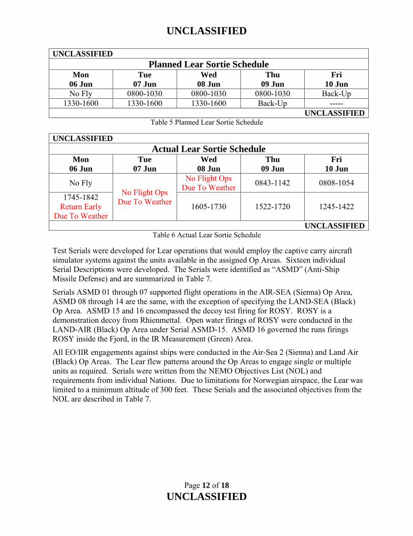
FOXTROT Flyable collected data for a total of 82 inbound runs on ships during 6 sorties on the Lear jet. A total of 31 decoy runs were recorded. The first sortie on 06 June was aborted early due to weather. The flights for 07 June and morning of 08 June were rescheduled due to poor weather conditions. FOXTROT SIP collected mid-wave IIR, visible band images and System Control Overlay Video of all of the listed runs. A summary of Lear runs conducted are found in Appendix 2.
FOXTROT Flyable experienced early problems with internal network communications preventing control. This problem was resolved and the system worked for the duration of the test.
IOTA-MIKE experienced a progressive processor failure. The processor failure caused gimbal control and camera focusing issues. This failure prevented it from operating for more than half of the later flight runs.
FOXTROT Flyable was operated in one of two modes, a man-in-the-loop mode, and a data collection mode for post processing analysis during the trial. The man in the loop run entails the operator operating the gimbal to scan the horizon for the targets of opportunity and initiating a track manually. The tracker did not simulate any specific threat missile, but rather operated in a generic centroid, binary threshold algorithm. The Data Acquisition Mode capture entailed the operator centering the image on the ship and collecting data as the system flew in. The data is full digital dynamic range which allows for high fidelity post processing of varying track algorithms and model validation.
6.2. FOXTROT Portable (Shore) Test Results
FOXTROT Portable collected data for a total of 66 runs on ships, 19 of which were decoy runs, during four days of testing. IIR and visible band imagery was recorded of eight ships at close ranges and all ship heading aspects. Target acquisition attained through man-in-the-loop mode to search and select a target of interest. After the target was selected, FOXTROT Portable used a generic centroid, binary threshold algorithm to track. Mid-wave IIR, 14 bit visible images and System Control Overlay Video collected for all of the listed runs. A summary of FOXTROT Portable (Shore) runs conducted are found in Appendix 4.
6.3. ROSY Decoy Demonstration
The evaluation of the decoy effectiveness against the imaging infrared (IIR) seekers was planned using the FOXTROT Flyable seeker simulator flying captive-carry on the Lear jet and the FOXTROT portable system set up on the shore site.
The NEMO 16 Trials offered a perfect opportunity to create and collect a data set of IIR imagery for future Science and Technology Organization (STO) Task group exploitations. This data set can be used in modeling runs for several member nations’ digital ASCM models. The critical component was to use an unclassified decoy, unclassified target boat and unclassified imager(s).

UNCLASSIFIED
Page 15 of 18
UNCLASSIFIED
Rhienmettal generously provided the organizers two ROSY tank defense decoy launchers and 120 rounds of red phosphorus decoys. The test organizers found a tug boat as the launch platform. The two launchers were mounted fore and aft at 15 degrees off axis, as shown in Figure 10. Figure 11 shows the ROSY installation on HNoMS Mjølner. STO also approved supplemental funding for expendables under their established policies. This allowed the Lear to fly against the tug and collect data. Netherlands provided a calibrated black body for FOXTROT Flyable and Portable systems to collect black body data before and after the sortie – a needed step for data to be used in modeling work.
The test was designed in two phases. The first set of runs was conducted against the tug placed within the operational area of the IIR shore site. This allowed for the assets at this site to image the event. The Lear flew a very tight approach against this configuration. This portion occurred at the beginning of the sortie. The FOXTROT ground system collected IIR and high resolution EO imagery.
Figure 10 ROSY Installation Locations
Figure 11 ROSY Installation on HNoMS Mjølner
The second phase was done towards the end of this sortie and conducted in the Land-Sea sector, which is located to the west of the Fjord entrance. This location only permitted Lear flights and was out of view for the Portable system. This allowed for more variations in the approach angle. Data collection included flying into the sun. Also collections approaching bow were done to allow for decoy signature/capture for future work.
Each run was to use ten rounds per event. One concern was the short duration of the rounds (3 seconds) but this proved to be more than enough. The tug was 25m long and the coverage offered was more than sufficient to allow for investigations into multi-munition decoy systems.

UNCLASSIFIED
Page 16 of 18
UNCLASSIFIED
There were 16 runs (7 successful decoys, 1 failure, 8 not post-processed) collected from the aircraft, and 7 from the shore side FOXTROT unit (3 successful decoys, and 4 failures). Run information and associated Run numbers are as shown in Table 8.
UNCLASSIFIED
System OpArea Run Numbers
FOXTROT Portable IR Measurement (Green) 12a – 18
FOXTROT (Lear) IR Measurement (Green) 12 – 19
FOXTROT (Lear) Land-Air (Black) 38 – 45
UNCLASSIFIED
Table 8 ROSY Run Information - 09 Jun 2016
UNCLASSIFIED
ROSY Decoy Demonstration Results
S/F/U/NO S= Successful; F=Failed; U=Unknown; NO=No Decoy Results of Foxtrot Flyable Simulator Run Result Comments
12-15 U Runs unable to be post-processed 16 F Separation between decoy and tug was clear enough, so Track Gate (TG) stayed on tug.
17 S Decoy covered tug completely. Elongated decoy cloud pulled TG away from tug and to the center of a cloud.
18 S Similar to Run 17. 19 S Similar to Run 17. Size and intensity of decoy moved TG away from tug. 38 NO Calibration Run. Not post-processed
39 S Decoy covered tug completely. After TG moved to the center of decoy cloud, tug moved away from cloud swiftly.
40 S Similar to Run39; Cloudy sky; Background was gray. Tug was hot on cooler water. 41 S Similar to Run39; Cloudy sky; Tug was hot on cooler water. 42 S Similar to Run39; Gray background but still clear horizon. 43 NO Tug was overlapped with other ship. Not post-processed
44 U Tug was in negative contrast; Unable to perform man-in-the-loop decoy test; sky was cooler (black) and water had lots of glints. Not post-processed
45 NO Tug was in negative contrast. Not post-processed
Results of Foxtrot Portable Simulator on Shore Site Run Result Comments 12a F Separation between tug and decoy was clear from seeker; Starboard Rear Quarter. 13 S Decoy fully covered tug; TG lost on water; Starboard Side. 14 F Separation between tug and decoy was clear from seeker; Bow Port Quarter. 15 F Separation between tug and decoy was clear from seeker; Bow Port Quarter.
16 F Decoy covered tug and TG expanded, seduced initially, but TG returned to the center and recaptured tug; Starboard. 10 Rounds.
17 S Decoy fully covered tug; tug escaped from decoy swiftly. TG lost on water; Starboard. 10 Rounds.
18 S Similar to Run 17; TG lost in sky; Starboard. 10 Rounds. UNCLASSIFIED
Table 9 Post-processing results of ROSY Decoys

UNCLASSIFIED
Page 17 of 18
UNCLASSIFIED
Table 9 shows the results of the ROSY decoy demonstration runs from both the Flyable and Portable FOXTROT simulators. A run was considered successful if the track gate initially on the ship was merged with the decoy and separated from the ship and then lost to some other parts of the background. If the decoy was launched such that it did not seduce the track gate away from the ship or later the track gate jumped back on the ship, then the run was considered a failure. For the Flyable simulator, seven of the eight runs against the model track gate stayed away from the ship. Three of the seven runs against the portable simulator were successful, and four runs failed. The four runs failed due to poor geometry and the decoy did not seduce the track gate away from the ship.
6.4. IOTA-MIKE
IOTA-MIKE flyable was operated in the man-in-the-loop mode during the Trial. This entails the operator scanning the horizon for the targets of opportunity and initiating a track manually. The tracker did not simulate any specific threat missile, but rather operated in a generic centroid, binary threshold algorithm. IOTA-MIKE being a visible band TV seeker simulator was not involved in decoy testing; however, was able to record the visible band imagery and tracking during ship runs as listed in Appendix 2. Specific results discussed between U.S. Subject Matter Expert and nation representatives during subsequent meeting.
Seven Ship Runs were recorded with IOTA-MIKE. Progressive hardware failures of the processor prevented further recording.
6.5. Decoy Runs
A total of 32 ship decoy runs were recorded by the two FOXTROT systems. Results of the individual decoy runs will not be included in this report, but will be turned over to the host nation for direct dissemination to their respective countries.
The ROSY run data (23 runs, 18 decoys) will be supplied to the host nation, and forwarded to the NATO Science & Technology Organization (STO), EO and IR Countermeasures against Anti-Ship Missiles Task Group (SCI-224).
6.6. CAWS Ground
The CAWS system was operated in conjunction with the German RF Simulator to provide a multi-threat environment. CAWS was only operated on Day 2 (07 June), participating in 22 runs.
Three signal groups were developed and provided for use in the NEMO Trials. The CAWS signals are detailed in Table 10. These signals were representative of threat type signals, but did not represent a specific threat. Mode 1 and 2 signals had frequency interference problems with other equipment, and only Mode 3a Waveform was transmitted.
CAWS transmits through a fixed horn, and produces an ERP of 40 dBw. Scanning simulation is achieved through the use of a program controlled attenuator which modulates signal power level to simulate a scanning system. For NEMO a Sector Scan was reproduced with a Scan Period of 4 seconds.
CAWS Run information is listed in Appendix 5.

UNCLASSIFIED
Page 18 of 18
UNCLASSIFIED
UNCLASSIFIED
Mode
Name
Frequency
(MHz)
Freq
Agile
Freq Agile
Range
(MHz)
PRI
(µs)
PRI
Agile
PRI Agile
Range
(µs)
PW
(µs) PW Agile
1a
8500.00
No ---
150.000
No ---
1.000 No 1b Yes ±150.0 No ---
1c Yes ±250.0 Yes ±50.0
2a
12500.000
No ---
150.000
No ---
1.000 No 2b Yes ±150.0 No ---
2c Yes ±250.0 Yes ±50.0
3a
15500.00
No ---
150.000
No ---
1.000 No 3b Yes ±150.0 No ---
3c Yes ±250.0 Yes ±50.0
UNCLASSIFIED
Table 10 CAWS Waveforms
CAWS signal summary:
1.a, 2.a, 3.a – Simple Signal - Fixed Frequency, Fixed PRI, Fixed PW
1.b, 2.b, 3.b – Frequency Modulated - Fixed PRI, Fixed PW, Frequency Sine Modulated ±150 MHz at 100 Hz rate
1.c, 2.c, 3.c – Frequency and PRI Modulated - Fixed PW, 10 position discrete frequencies (500 MHz bandwidth) and 10 discrete PRI values (100 µsec variation, 10 µsec steps)
7. NRL Summary
The primary objective of this trial was to take EO/IIR imagery of various platforms and to evaluate the effectiveness of IIR decoys and deployment tactics against imaging infrared (IIR) seekers. The secondary mission was to support ESM operations by transmitting a radar signal with the CAWS system. All proposed U.S. test objectives were met.
In operations with multiple ships it is critical to be able to locate and identify of each unit. The use of TACAN and AIS during testing ensures that aircraft are inbound to correct ship under test. This is extremely important when unit is firing decoys, to avoid the loss of data.
The Foxtrot flyable system collected over 776 files consisting of 314M bytes of data. The system collected both visible and mid wave IR imagery and GPS tracking data for 86 ship runs.
The Foxtrot portable system collected over 467 files consisting of 1.6T bytes of data. The system collected both visible and mid wave IR imagery for 66 ship runs.
The IOTA-MIKE system collected over 239 files consisting of 205M bytes of data. The system collected visible band imagery and GPS tracking data for 6 ship runs.
The CAWS Stimulator operated for 22 runs, providing a multiple threat environment in conjunction with the German RF Simulator.

UNCLASSIFIED
Page App 1-1 of 1
UNCLASSIFIED
Appendix 1 EO/IIR Simulator Configuration
UNCLASSIFIED
FOXTROT Flyable SIP IOTA-MIKE Flyable SIP FOXTROT Portable
System Type Man-in-the-Loop, imaging IIR Man-in-the-Loop, imaging Visible
Same as FOXTROT SIP
Gimbal Limits AZ = +/- 20°, EL = +8° / -17°
AZ = +/- 20°, EL = +8° / -17°
AZ = +/- 20°, EL = +2.5° / -10°
Camera Type IIR Cincinnati Electronics NightConqueror II-256
COHU Model 3810 Same as FOXTROT SIP
Sensor Type InSb Photovoltaic FPA CCD color camera Same as FOXTROT SIP
Readout CMOS switched FET, read while integrate
Same as FOXTROT SIP
FPA Format 256(h) x 256(v) pixels NTSC Same as FOXTROT SIP
FPA Pixel Pitch 30 μm Same as FOXTROT SIP
FPA Dimension 7.68 mm (h) x 7.68 mm (v) Same as FOXTROT SIP
Optical Band 3.6 - 5.0 μm Nominal Visible Same as FOXTROT SIP
Optics Assembly Dual FOV motorized lens, f/4, 50/250 mm EFL
22X 3.9mm to 85.8mm
Dual FOV manual lens, f/4, 50/250 mm EFL
Wide FOV 7° x 7° 2.51° Same as FOXTROT SIP
Narrow FOV 3° x 3° 48.94° Same as FOXTROT SIP
Analog Output RS-170 Video NTSC Same as FOXTROT SIP
Digital Output 14-bit HOTlink at 22.1 MByte/sec Same as FOXTROT SIP
Cooler Ricor K508 rotary Stirling cooler N/A Same as FOXTROT SIP
Reference Camera Model 3810 None Monochrome 14 Bit
Visible Manufacturer COHU N/A Photon Focus Camera Type CCD color camera N/A CMOS Image Area 3.6 x 2.7 mm (1/4 inch format) N/A Cell Size NTSC: 4.75 (h) x 5.55 μm (v)
PAL: 4.85 (h) x 4.65 μm (v) N/A
Number of pixels 768(h) x 494(v) = 379392 pixels N/A 1312 x 1082 pixels Video Resolution NTSC: 460 lines (h) x 250 (v)
PAL: 450 lines (h) x 415 (v) N/A NTSC: 470 lines (h)
PAL: 460 lines (h) Lens (Wide/Tele) 3.9 / 85.8 mm N/A 2.4 / 60 mm Optical/Digital Zoom
22x / 8x N/A 25x / 12x
Angle of view (h) 48.94° (Wide) / 2.51° (Tele) N/A 45° (Wide) / 2.0° (Tele) Max. Lens Aperture
Wide: f/1.6; Tele: f/3.7 N/A Wide: f/1.6; Tele: f/2.7
S/N ratio 56 dB N/A 49 dB UNCLASSIFIED

UNCLASSIFIED
Page App 2-1 of 3
UNCLASSIFIED
Appendix 2 Summary of Lear FOXTROT Runs
UNCLASSIFIED
Date Run Start/Stop
Time(Z) Ship Series Decoy
8-Jun-16 3* 1424/1426 Blas de Lezo ASMD 01 No 8-Jun-16 4* 1435/1436 Blas de Lezo ASMD 03 No 8-Jun-16 5* 1444/1436 Blas de Lezo ASMD 02 Yes 8-Jun-16 6* 1453/1456 Blas de Lezo ASMD 03 No 8-Jun-16 7* 1503/1506 Blas de Lezo ASMD 04 No 8-Jun-16 8* 1511/1514 Blas de Lezo ASMD 04 No 9-Jun-16 12* 0656/0657 Mjølner ASMD 16 No 9-Jun-16 13* 0658/0700 Mjølner ASMD 16 No 9-Jun-16 14* 0702/0703 Mjølner ASMD 16 Yes 9-Jun-16 15* 0705/0707 Mjølner ASMD 16 Yes 9-Jun-16 16* 0709/0711 Mjølner ASMD 16 Yes 9-Jun-16 17* 0713/0714 Mjølner ASMD 16 Yes 9-Jun-16 18* 0718/0720 Mjølner ASMD 16 Yes 9-Jun-16 19* 0724/0725 Mjølner ASMD 16 Yes 9-Jun-16 19a* 0743/0745 Barbaros ASMD 09 Yes 9-Jun-16 20* 0746/0748 Aquitaine ASMD 08 No 9-Jun-16 21* 0749/0751 Blas de Lezo ASMD 08 No 9-Jun-16 22* 0752/0754 Barbaros ASMD 09 Yes 9-Jun-16 23* 0755/0757 Aquitaine ASMD 10 No 9-Jun-16 24* 0757/0759 Niels Juel ASMD 08 No 9-Jun-16 25* 0800/0802 Roald Amundsen ASMD 08 No 9-Jun-16 26* 0803/0805 Barbaros ASMD 09 Yes 9-Jun-16 27* 0806/0808 Aquitaine ASMD 09 No 9-Jun-16 28* 0809/0810 Blas de Lezo ASMD 10 No 9-Jun-16 29* 0812/0814 Roald Amundsen ASMD 10 No 9-Jun-16 30* 0815/0817 Barbaros ASMD 09 Yes 9-Jun-16 31* 0819/0821 Aquitaine ASMD 10 No 9-Jun-16 32* 0822/0824 Niels Juel ASMD 10 No 9-Jun-16 33* 0825/0827 Roald Amundsen ASMD 10 No 9-Jun-16 34* 0828/0830 Barbaros ASMD 09 Yes 9-Jun-16 35* 0832/0833 Aquitaine ASMD 09 Yes 9-Jun-16 36* 0838/0840 Aquitaine ASMD 10 No 9-Jun-16 37* 0845/0847 Aquitaine ASMD 10 No 9-Jun-16 38* 0855/0857 Mjølner ASMD 15 No 9-Jun-16 39 0901/0903 Mjølner ASMD 15 Yes
UNCLASSIFIED

UNCLASSIFIED
Page App 2-2 of 3
UNCLASSIFIED
UNCLASSIFIED
Date Run Start/Stop
Time(Z) Ship Series Decoy
9-Jun-16 40 0905/0907 Mjølner ASMD 15 Yes 9-Jun-16 41 0910/0911 Mjølner ASMD 15 Yes 9-Jun-16 42 0917/0918 Mjølner ASMD 15 Yes 9-Jun-16 43 0923/0924 Mjølner ASMD 15 No 9-Jun-16 44 0928/0929 Mjølner ASMD 15 Yes 9-Jun-16 45 0933/0934 Mjølner ASMD 15 No 9-Jun-16 46 1330/1332 Leopold I ASMD 08 No 9-Jun-16 47 1332/1334 Barbaros ASMD 08 No 9-Jun-16 48 1340/1342 Leopold I ASMD 08 No 9-Jun-16 49 1346/1350 Barbaros ASMD 09 Yes 9-Jun-16 50 1354/1358 Leopold I ASMD 09 Yes 9-Jun-16 51* 1403/1407 Barbaros ASMD 09 Yes 9-Jun-16 52* 1410/1413 Leopold I ASMD 09 Yes 9-Jun-16 53* 1418/1420 Barbaros ASMD 08 No 9-Jun-16 54* 1425/1429 Leopold I ASMD 09 Yes 9-Jun-16 55* 1432/1436 Barbaros ASMD 09 Yes 9-Jun-16 56* 1440/1442 Leopold I ASMD 09 Yes 9-Jun-16 57* 1454/1456 Barbaros ASMD 10 No 9-Jun-16 58* 1459/1501 Leopold I ASMD 10 No 9-Jun-16 59* 1506/1508 Barbaros ASMD 11 No
10-Jun-16 60* 0628/0630 De Ruyter ASMD 08 No 10-Jun-16 61* 0634/0636 Blas de Lezo ASMD 09 Yes 10-Jun-16 62* 0641/0643 Leopold I ASMD 08 No 10-Jun-16 63* 0648/0651 Aquitaine ASMD 08 No 10-Jun-16 64* 0655/0658 De Ruyter ASMD 10 No 10-Jun-16 65* 0702/0704 Blas de Lezo ASMD 10 No 10-Jun-16 66* 0709/0712 Leopold I ASMD 10 No 10-Jun-16 67* 0719/0721 Aquitaine ASMD 09 Yes 10-Jun-16 68* 0726/0727 De Ruyter ASMD 10 No 10-Jun-16 69* 0731/0734 De Ruyter ASMD 10 No 10-Jun-16 70* 0738/0740 Blas de Lezo ASMD 10 No 10-Jun-16 71* 0745/0748 Aquitaine ASMD 09 Yes 10-Jun-16 72* 0754/0757 De Ruyter ASMD 09 Yes 10-Jun-16 73 0800/0805 Blas de Lezo ASMD 10 No 10-Jun-16 74 0808/0811 Aquitaine ASMD 10 No 10-Jun-16 75 0816/0819 De Ruyter ASMD 09 Yes 10-Jun-16 76 0824/0826 Blas de Lezo ASMD 10 No
UNCLASSIFIED

UNCLASSIFIED
Page App 2-3 of 3
UNCLASSIFIED
UNCLASSIFIED
Date Run Start/Stop
Time(Z) Ship Series Decoy
10-Jun-16 77* 0831/0833 Aquitaine ASMD 10 No 10-Jun-16 78* 0839/0843 De Ruyter ASMD 09 Yes 10-Jun-16 79* 1059/1102 De Ruyter ASMD 08 No 10-Jun-16 80* 1105/1108 De Ruyter ASMD 10 No 10-Jun-16 81* 1115/1119 De Ruyter ASMD 10 No 10-Jun-16 82* 1126/1129 De Ruyter ASMD 10 No 10-Jun-16 83* 1135/1138 De Ruyter ASMD 10 No 10-Jun-16 84* 1144/1147 De Ruyter ASMD 10 No 10-Jun-16 85* 1152/1157 De Ruyter ASMD 10 No 10-Jun-16 86* 1202/1204 De Ruyter ASMD 10 No
UNCLASSIFIED
* DA-20 aircraft flew in formation
UNCLASSIFIED
Page App 3-1 of 1
UNCLASSIFIED
Appendix 3 Summary of Lear IOTA-MIKE Runs
UNCLASSIFIED
Date Run Start/Stop
Time(Z) Ship Series Decoy
8-Jun-16 3 1424/1426 Blas de Lezo ASMD 01 No 8-Jun-16 4 1435/1436 Blas de Lezo ASMD 03 No 8-Jun-16 5 1444/1436 Blas de Lezo ASMD 02 Yes 8-Jun-16 6 1453/1456 Blas de Lezo ASMD 03 No 8-Jun-16 7 1503/1506 Blas de Lezo ASMD 04 No 8-Jun-16 8 1511/1514 Blas de Lezo ASMD 04 No
UNCLASSIFIED

UNCLASSIFIED
Page App 4-1 of 2
UNCLASSIFIED
Appendix 4 Summary of FOXTROT Portable (Shore) Runs
UNCLASSIFIED
Date Run Start/Stop
Time(Z) Ship
NEMO
Objective Decoy
7-Jun-16 1 0639/0647 Blas de Lezo S1 No 7-Jun-16 2 0648/0649 Blas de Lezo S1 No 7-Jun-16 3 0651/0652 Blas de Lezo S1 No 7-Jun-16 4 0655/0702 Blas de Lezo S1 No 7-Jun-16 5 0707/0709 Blas de Lezo S1 No 7-Jun-16 6 0715/0719 Blas de Lezo S1 No 7-Jun-16 7 0722/0725 Blas de Lezo S1 No 7-Jun-16 8 0735/0738 Blas de Lezo S1 No 7-Jun-16 9 0815/0820 Blas de Lezo S1 No 7-Jun-16 10 0825/0830 Blas de Lezo S1 No 7-Jun-16 11 0831/0835 Blas de Lezo S1 No 7-Jun-16 12 1124/1131 Blas de Lezo S1 No 7-Jun-16 13 1205/1210 De Ruyter S1 No 7-Jun-16 14 1227/1231 De Ruyter S1 No 7-Jun-16 15 1239/1243 De Ruyter S1 No 7-Jun-16 16 1254/1259 De Ruyter S1 No 7-Jun-16 17 1305/1311 Niels Juel S1 No 7-Jun-16 18 1325/1330 Niels Juel S1 No 7-Jun-16 19 1356/1402 Niels Juel S1 No 7-Jun-16 20 1422/1427 Niels Juel S1 (3.2) No 7-Jun-16 21 1442/1447 Niels Juel S1 (3.2) No 7-Jun-16 22 1448/1454 Niels Juel S1 (1.1) No 7-Jun-16 23 1456/1459 Niels Juel S1 (1.1) No 7-Jun-16 24 1502/1505 Niels Juel S1 (1.1) No 7-Jun-16 25 1514/1518 Niels Juel S1 (1.5) No 8-Jun-16 1 1035/1036 Roald Amundsen S1 No 8-Jun-16 2 1049/1050 Roald Amundsen S1 No 8-Jun-16 3 1056/1059 Roald Amundsen S1 (1.1) No 8-Jun-16 4 1116/1119 Roald Amundsen S1 (1.5) No 8-Jun-16 5 1120/1122 Roald Amundsen S1 (1.5) No 8-Jun-16 6 1129/1131 Roald Amundsen S1 (1.5) No 8-Jun-16 7 1132/1134 Roald Amundsen S1 (1.5) No 8-Jun-16 8 1441/1415 Roald Amundsen D1 Yes 8-Jun-16 9 1719/1723 De Ruyter U7 Yes 8-Jun-16 10 1733/1737 Roald Amundsen U7 Yes 8-Jun-16 11 1743/1745 Roald Amundsen U7 Yes
UNCLASSIFIED

UNCLASSIFIED
Page App 4-2 of 2
UNCLASSIFIED
UNCLASSIFIED
Date Run Start/Stop
Time(Z) Ship
NEMO
Objective Decoy
8-Jun-16 12 1747/1751 Roald Amundsen U7 Yes 9-Jun-16 12a 0646/0650 Mjølner U7 Yes 9-Jun-16 13 0655/0659 Mjølner U7 Yes 9-Jun-16 14 0703/0705 Mjølner U7 Yes 9-Jun-16 15 0707/0710 Mjølner U7 Yes 9-Jun-16 16 0713/0715 Mjølner U7 Yes 9-Jun-16 17 0718/0721 Mjølner U7 Yes 9-Jun-16 18 0729/0733 Mjølner U7 Yes 9-Jun-16 19 0841/0845 Storm S1 (1.1) No 9-Jun-16 20 0904/0908 Storm S1 No 9-Jun-16 21 0912/0917 Storm S1 (1.5) No 9-Jun-16 22 0919/0923 Storm S1 (1.2) No 9-Jun-16 23 0926/0930 Storm S1 (1.2) No 9-Jun-16 24 1142/1147 Storm S1 (3.2) No 9-Jun-16 25 1155/1200 Roald Amundsen N/S No 9-Jun-16 26 1213/1218 Leopold I N/S No 9-Jun-16 27 1241/1246 Storm U7 Yes 9-Jun-16 28 1249/1254 Storm U7 Yes 9-Jun-16 29 1301/1306 Storm U7 Yes 10-Jun-16 30 0659/0701 Barbaros S1 No 10-Jun-16 31 0702/0703 Barbaros S1 No 10-Jun-16 32 0707/0708 Barbaros S1 No 10-Jun-16 33 0733/0734 Barbaros S1 (1.5) No 10-Jun-16 34 0736/0740 Barbaros S1 (1.5) No 10-Jun-16 35 0816/0819 Barbaros S1 (1.3) No 10-Jun-16 36 1050/1052 Aquitaine N/S No 10-Jun-16 37 1127/1129 Barbaros U7 (4.1) Yes 10-Jun-16 38 1137/1140 Barbaros U7 (4.1) Yes 10-Jun-16 39 1149/1152 Barbaros U7 (4.3) Yes 10-Jun-16 40 1205/1207 Barbaros U7 (4.4) Yes
UNCLASSIFIED

UNCLASSIFIED
Page App 5-1 of 1
UNCLASSIFIED
Appendix 5 Summary of CAWS Runs
UNCLASSIFIED
Event
Run #
CAWS
Run # Time On Time Off Test Unit Notes
2 1 082407 082609 Target called as NOVEMBER
by RF, AIS shows NOVEMBER in port. Appears
to be OSCAR
3 2 083305 083509
4 3 083903 084132
5 4 084502 084703
1 5 095008 095232 Steil
1 6 095604 100133 Steil
2 7 100422 100512 Steil
3 8 100815 101015 Steil
4 9 101308 101417 Steil
5 10 104842 100529 Steil
6 11 105534 105727 Steil
7 12 110012 110205 Steil
8 13 110516 110656 Steil
9 14 111133 111315 Steil
10 15 111704 111925 Steil
12 16 112908 113053 Steil
13 17 113628 113648 Steil
14 18 113911 114046 Steil
15 19 114308 114525 Steil
16 20 114905 115128 Steil
17 21 115419 115652 Steil
1 1 131349 131709 Leopold I
UNCLASSIFIED

UNCLASSIFIED
Page App 6-1 of 1
UNCLASSIFIED
Appendix 6 Results of ROSY Demo Runs
UNCLASSIFIED
Date Run Start/Stop
Time(Z) Ship Series Sim
Result
Seduction
9-Jun-16 12a 0646/0650 Mjølner ASMD 02 Foxtrot Portable No
9-Jun-16 13 0655/0659 Mjølner ASMD 02 Foxtrot Portable Yes
9-Jun-16 14 0703/0705 Mjølner ASMD 02 Foxtrot Portable No
9-Jun-16 15 0707/0710 Mjølner ASMD 02 Foxtrot Portable No
9-Jun-16 16 0713/0715 Mjølner ASMD 02 Foxtrot Portable No
9-Jun-16 17 0718/0721 Mjølner ASMD 02 Foxtrot Portable Yes
9-Jun-16 18 0729/0733 Mjølner ASMD 02 Foxtrot Portable Yes
9-Jun-16 12 0656/0657 Mjølner ASMD 02 Foxtrot SIP N/A
9-Jun-16 13 0658/0700 Mjølner ASMD 02 Foxtrot SIP N/A
9-Jun-16 14 0702/0703 Mjølner ASMD 02 Foxtrot SIP N/A
9-Jun-16 15 0705/0707 Mjølner ASMD 02 Foxtrot SIP N/A
9-Jun-16 16 0709/0711 Mjølner ASMD 02 Foxtrot SIP No
9-Jun-16 17 0713/0714 Mjølner ASMD 02 Foxtrot SIP Yes
9-Jun-16 18 0718/0720 Mjølner ASMD 02 Foxtrot SIP Yes
9-Jun-16 19 0724/0725 Mjølner ASMD 02 Foxtrot SIP Yes
9-Jun-16 38 0855/0857 Mjølner ASMD 02 Foxtrot SIP N/A
9-Jun-16 39 0901/0903 Mjølner ASMD 02 Foxtrot SIP Yes
9-Jun-16 40 0905/0907 Mjølner ASMD 02 Foxtrot SIP Yes
9-Jun-16 41 0910/0911 Mjølner ASMD 02 Foxtrot SIP Yes
9-Jun-16 42 0917/0918 Mjølner ASMD 02 Foxtrot SIP Yes
9-Jun-16 43 0923/0924 Mjølner ASMD 02 Foxtrot SIP N/A
9-Jun-16 44 0928/0929 Mjølner ASMD 02 Foxtrot SIP N/A 9-Jun-16 45 0933/0934 Mjølner ASMD 02 Foxtrot SIP N/A
UNCLASSIFIED

UNCLASSIFIED
Page App 7-1 of 1
UNCLASSIFIED
Appendix 7 Acronyms
UNCLASSIFIED
Acronym Description
ASCM Anti-Ship Cruise Missile ASM Anti-Ship Missile ASMD Anti-Ship Missile Defense AWWCG NATO Above Water Warfare Capabilities Group reporting to NNAG CAWS NRL Complex Arbitrary Waveform Synthesizer – Programmable I and J Band Radar
Stimulator ENEWS NRL Effectiveness of Navy Electronic Warfare Systems Program EO Electro Optical IIR Imaging Infra-Red JEWCS NATO military organization tasked with providing a wide variety of capabilities
related to the domain of Electronic Warfare (EW) MARCSS Norwegian Navy Operational Logistics Unit NATO North Atlantic Treaty Organization NEMO Naval Electro-Magnetic Operations NNAG NATO Naval Armaments Group NOL NEMO Objectives List NRL United States Naval Research Laboratory RF Radio Frequency ROSY Rheinmetall Rapid Obscuring System capable of rapidly obscuring the line of sight,
the ROSY 40 mm countermeasure system protects vessels from littoral and riverine threats such as small arms fire, RPGs and missiles
SCI Systems Concepts and Integration (SCI) Panel is to advance knowledge concerning advanced systems, concepts, integration, engineering techniques and technologies across the spectrum of platforms and operating environments to assure cost-effective mission area capabilities
SCI-224 NATO Scientific Concepts and Integration Group for EO and IR Countermeasures against Anti-Ship Missiles
SCI-293 NATO Scientific Concepts and Integration Group providing continuity of annual NEMO Trials
SIP Standard Instrumentation Pod STO NATO Science and Technology Organization responsible for scientific research,
technology development, transition, application and field-testing, experimentation and a range of related scientific activities that include systems engineering, operational research and analysis, synthesis, integration and validation of knowledge derived through the scientific method
TEWD Tactical Electronic Warfare Division of US Naval Research Laboratory UAS Unmanned Aerial System
UNCLASSIFIED

UNCLASSIFIED
UNCLASSIFIED