Embed Size (px)
Citation preview
NIPPON STEEL TECHNICAL REPORT No. 92 July 2005
- 51 -
UDC 621 . 791 . 753 . 9 - 52 : 621 . 644
*1 Energy Facilities, Civil Engineering & Marine Construction Division *2 Steel Research Laboratories
Automatic Control Technologyof Welding Machine MAG-II for Onshore Pipelines
Satoshi NAKAMURA*1 Yuichi FURUKAWA*1
Yasuyuki IKUNO*1 Shinji KODAMA*2
Tsuyoshi MAEDA*2
Abstract
The authors developed a new, automatic narrow groove welding system MAG-II
for onshore gas pipelines. It has a through-the-arc sensor (arc sensor) and a vision-
based sensor. The vision-based sensor is used for controlling the traveling speed and
oscillation width for the root pass. The arc sensor is used for controlling the torch
position and torch oscillation width for hot and filler passes. MAG-II equipped with
these sensors enables high quality girth welding at field.
1. IntroductionFor gas pipeline construction in Japan, the introduction of auto-
matic welding machines began to be considered for welding large-and medium-diameter steel pipes in the 1970s, and the automaticwelding of pipes for high-pressure gas pipelines was rather firmlyestablished in the 1990s. Since the mid 1990s, Nippon Steel hasbeen developing a welding system MAG-I to assure weld qualityand for higher-speed welding performance, NSC has developed andintroduced in site work an automatic welding system MAG-II. Thispaper mainly describes technical aspects of the MAG-II automaticcontrol.
2. Characteristics of MAG-II2.1 System configuration
Fig. 1 and Table 1 show the system configuration and the speci-fication of MAG-II. MAG-II consists of: (1) a welding head; (2) acontroller; (3) pendant box; (4) guide rail; (5) an internal clampingmachine; (6) a power supply; and (7) shield gas.
By the combination of the pinion gear of the welding head andthe rack formed on a guide rail suited for a steel pipe size between12”O.D. and 36”O.D., this system performs high-speed welding withone or two heads, while providing high-precision speed control.Photo 1 illustrates MAG-II performing two-head welding.2.2 Welding process
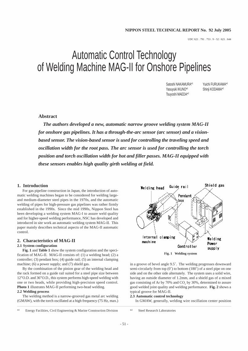
The welding method is a narrow-grooved gas metal arc welding(GMAW), with the torch oscillated at a high frequency (75 Hz, max.)
in a groove of bevel angle 9.5˚. The welding progresses downwardsemi-circularly from top (0˚) to bottom (180˚) of a steel pipe on oneside and on the other side alternately. The system uses a solid wire,having an outside diameter of 1.2mm, and a shield gas of a mixedgas consisting of Ar by 70% and CO
2 by 30%, determined to assure
good welded joint quality and welding performance. Fig. 2 shows atypical groove for MAG-II.2.3 Automatic control technology
In GMAW, generally, welding wire oscillation center position
Fig. 1 Welding system
NIPPON STEEL TECHNICAL REPORT No. 92 July 2005
- 52 -
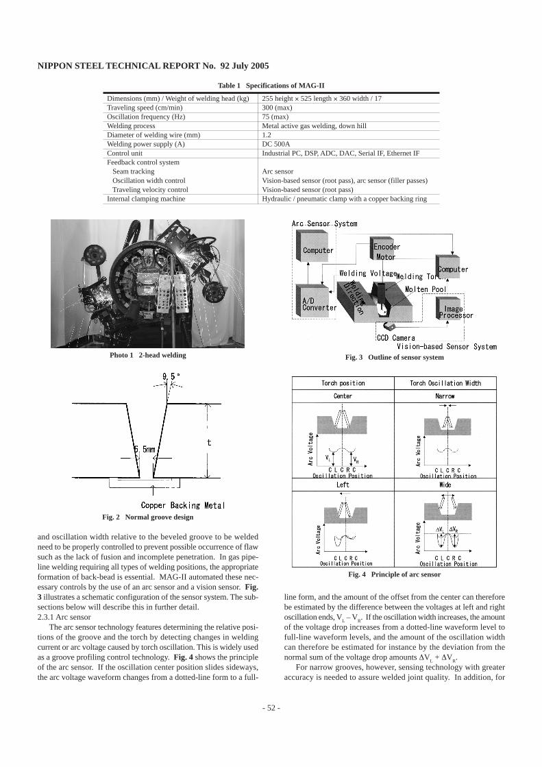
and oscillation width relative to the beveled groove to be weldedneed to be properly controlled to prevent possible occurrence of flawsuch as the lack of fusion and incomplete penetration. In gas pipe-line welding requiring all types of welding positions, the appropriateformation of back-bead is essential. MAG-II automated these nec-essary controls by the use of an arc sensor and a vision sensor. Fig.3 illustrates a schematic configuration of the sensor system. The sub-sections below will describe this in further detail.2.3.1 Arc sensor
The arc sensor technology features determining the relative posi-tions of the groove and the torch by detecting changes in weldingcurrent or arc voltage caused by torch oscillation. This is widely usedas a groove profiling control technology. Fig. 4 shows the principleof the arc sensor. If the oscillation center position slides sideways,the arc voltage waveform changes from a dotted-line form to a full-
line form, and the amount of the offset from the center can thereforebe estimated by the difference between the voltages at left and rightoscillation ends, V
L – V
R. If the oscillation width increases, the amount
of the voltage drop increases from a dotted-line waveform level tofull-line waveform levels, and the amount of the oscillation widthcan therefore be estimated for instance by the deviation from thenormal sum of the voltage drop amounts ∆V
L + ∆V
R.
For narrow grooves, however, sensing technology with greateraccuracy is needed to assure welded joint quality. In addition, for
Photo 1 2-head welding
Fig. 2 Normal groove design
Fig. 3 Outline of sensor system
Table 1 Specifications of MAG-II
Dimensions (mm) / Weight of welding head (kg)Traveling speed (cm/min)Oscillation frequency (Hz)Welding processDiameter of welding wire (mm)Welding power supply (A)Control unitFeedback control system Seam tracking Oscillation width control Traveling velocity controlInternal clamping machine
255 height × 525 length × 360 width / 17300 (max)75 (max)Metal active gas welding, down hill1.2DC 500AIndustrial PC, DSP, ADC, DAC, Serial IF, Ethernet IF
Arc sensorVision-based sensor (root pass), arc sensor (filler passes)Vision-based sensor (root pass)Hydraulic / pneumatic clamp with a copper backing ring
Fig. 4 Principle of arc sensor
NIPPON STEEL TECHNICAL REPORT No. 92 July 2005
- 53 -
welding pipes at horizontally fixed pipelines, various welding con-ditions were used depending on welding positions, and enhancedsensing accuracy particularly in low current regions was an importantrequirement because arc voltage fluctuations due to short-circuit trans-fer in low current regions could degrade the sensing accuracy.
To solve those problems, MAG-II has a high-frequency oscilla-tion mechanism with unique arc sensor design that can freely set uposcillation frequency and oscillation width.1) Seam tracking system
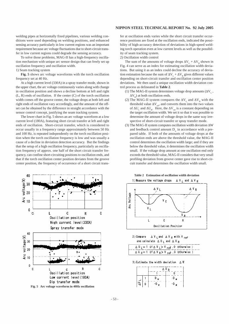
Fig. 5 shows arc voltage waveforms with the torch oscillationfrequency set at 40 Hz.
At a high current level (330A) in a spray transfer mode, shown inthe upper chart, the arc voltage continuously varies along with changein oscillation position and shows a decline bottom at left and right(L, R) ends of oscillation. If the center (C) of the torch oscillationwidth comes off the groove center, the voltage drops at both left andright ends of oscillation vary accordingly, and the amount of the off-set can be obtained by the difference in straight accordance with thesensor control concept, justifying the seam tracking system.
The lower chart in Fig. 5 shows an arc voltage waveform at a lowcurrent level (180A), featuring short circuit transfer at left and rightends of oscillation. Short-circuit transfer, which is considered tooccur usually in a frequency range approximately between 50 Hzand 100 Hz, is repeated independently on the torch oscillation posi-tion when the torch oscillation frequency is low and was usually acause of a decline in deviation detection accuracy. But the findingsthat the setup of a high oscillation frequency, particularly an oscilla-tion frequency of approx. one half of the short circuit transfer fre-quency, can confine short-circuiting positions to oscillation ends, andthat if the torch oscillation center position deviates from the groovecenter position, the frequency of occurrence of a short circuit trans-
fer at oscillation ends varies while the short circuit transfer occur-rence positions are fixed at the oscillation ends, indicated the possi-bility of high-accuracy detection of deviations in high-speed weld-ing torch operation even at low current levels as well as the possibil-ity of seam tracking system.2) Oscillation width control
The sum of the amounts of voltage drops ∆VL + ∆V
R shown in
Fig. 4 can serve as an index for estimating oscillation width devia-tions. But using it as an index could decline the accuracy of devia-tion estimation because the sum of ∆V
L + ∆V
R gives different values
depending on short-circuit transfer and oscillation center positiondeviations. We then used a unique oscillation width deviation con-trol process as delineated in Table 2.
(1) The MAG-II system determines voltage drop amounts (∆VL ,
∆VR) at both oscillation ends.
(2) The MAG-II system compares the ∆VL and ∆V
R with the
threshold value ∆Vref
, and converts them into the two valuesof ∆U
L and ∆U
R. Here, the ∆V
ref is a constant depending on
the target oscillation width. We set it so that it was possible todetermine the amount of voltage drops in the same way irre-spective of short-circuit transfer or spray transfer mode.
(3) The MAG-II system computes oscillation width deviation ∆Wand feedback control amount D
w in accordance with a pre-
pared table. If both of the amounts of voltage drops at theoscillation ends are above the threshold value, the MAG-IIcontrol determines the oscillation width large; and if they arebelow the threshold value, it determines the oscillation widthsmall. If the voltage drop amount at one oscillation end onlyexceeds the threshold value, MAG-II considers that very smallprofiling deviation from groove center gave rise to short-cir-cuit transfer and determines the oscillation width small.
Fig. 5 Arc voltage waveform in 40Hz oscillation
Table 2 Estimation of oscillation width deviation
NIPPON STEEL TECHNICAL REPORT No. 92 July 2005
- 54 -
By repeating the processing of the steps described above for eve-ry oscillation cycle, MAG-II can perform high-precision control ofoscillation width1).2.3.2 Vision-based sensor2)
1) System configurationAs shown in Fig. 3, the vision-based sensor system has a CCD
camera fitted with an interference filter that is arranged so that themain transmission waveform is in the near infrared region frontwardin the welding direction. Images of molten pool are taken into animage processor, where image measurements and control amountsare generated. Oscillation width profiling control and back-bead con-trol are also performed. The following subsections describe the back-bead control in particular.2) Precedence length measurement and back-bead control
The following is an investigation of molten pool images and back-bead formation in welding.
A CCD camera arranged as shown in Fig. 6 revealed that therelative positions of the arc point and molten pool end can signifi-cantly affect the formation of the back-bead, and that a good beadcan be formed there if the distance between the bottom of the moltenpool image (the front end of molten pool) and the bottom of thewelding wire image (hereinafter referred to as precedence length ofmolten pool, PL) is within a certain range.
Letting PWY represent Y ordinates for the welding wire endknown from a characteristic point in the molten pool image shownin Fig. 7 and by measurement, and PSY represent Y ordinates for thebottom at the center of the molten pool, the equation below is at-tained.
PL = PSY – PWYBy using a median of data around PL detection and by letting φ
denote a position angle at the time of detection, we obtain smootheddate PLmed(φ). If we let PLstd(φ) be a standard precedence lengthat the position angle φ and enter the difference δPL from PLmed(φ)into the speed control function graph in Fig. 8, the speed increment/
decrement value δV (%) is computed and is transmitted as a speedcontrol command to the control panel of the welding system.3) Results of back-bead control experiment using precedence length
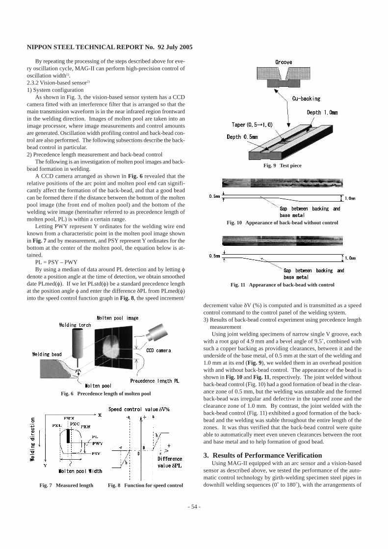
measurementUsing joint welding specimens of narrow single V groove, each
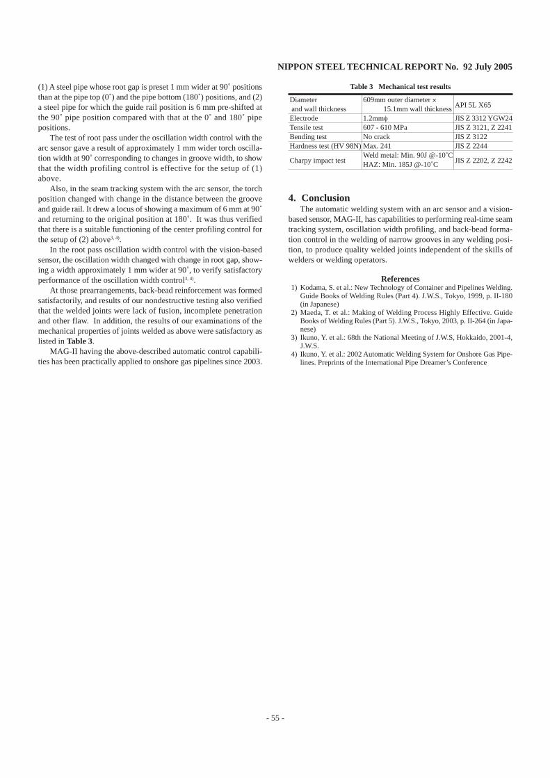
with a root gap of 4.9 mm and a bevel angle of 9.5˚, combined withsuch a copper backing as providing clearances, between it and theunderside of the base metal, of 0.5 mm at the start of the welding and1.0 mm at its end (Fig. 9), we welded them in an overhead positionwith and without back-bead control. The appearance of the bead isshown in Fig. 10 and Fig. 11, respectively. The joint welded withoutback-bead control (Fig. 10) had a good formation of bead in the clear-ance zone of 0.5 mm, but the welding was unstable and the formedback-bead was irregular and defective in the tapered zone and theclearance zone of 1.0 mm. By contrast, the joint welded with theback-bead control (Fig. 11) exhibited a good formation of the back-bead and the welding was stable throughout the entire length of thezones. It was thus verified that the back-bead control were quiteable to automatically meet even uneven clearances between the rootand base metal and to help formation of good bead.
3. Results of Performance VerificationUsing MAG-II equipped with an arc sensor and a vision-based
sensor as described above, we tested the performance of the auto-matic control technology by girth-welding specimen steel pipes indownhill welding sequences (0˚ to 180˚), with the arrangements of
Fig. 6 Precedence length of molten pool
Fig. 7 Measured length Fig. 8 Function for speed control
Fig. 11 Appearance of back-bead with control
Fig. 10 Appearance of back-bead without control
Fig. 9 Test piece
NIPPON STEEL TECHNICAL REPORT No. 92 July 2005
- 55 -
(1) A steel pipe whose root gap is preset 1 mm wider at 90˚ positionsthan at the pipe top (0˚) and the pipe bottom (180˚) positions, and (2)a steel pipe for which the guide rail position is 6 mm pre-shifted atthe 90˚ pipe position compared with that at the 0˚ and 180˚ pipepositions.
The test of root pass under the oscillation width control with thearc sensor gave a result of approximately 1 mm wider torch oscilla-tion width at 90˚ corresponding to changes in groove width, to showthat the width profiling control is effective for the setup of (1)above.
Also, in the seam tracking system with the arc sensor, the torchposition changed with change in the distance between the grooveand guide rail. It drew a locus of showing a maximum of 6 mm at 90˚and returning to the original position at 180˚. It was thus verifiedthat there is a suitable functioning of the center profiling control forthe setup of (2) above3, 4).
In the root pass oscillation width control with the vision-basedsensor, the oscillation width changed with change in root gap, show-ing a width approximately 1 mm wider at 90˚, to verify satisfactoryperformance of the oscillation width control3, 4).
At those prearrangements, back-bead reinforcement was formedsatisfactorily, and results of our nondestructive testing also verifiedthat the welded joints were lack of fusion, incomplete penetrationand other flaw. In addition, the results of our examinations of themechanical properties of joints welded as above were satisfactory aslisted in Table 3.
MAG-II having the above-described automatic control capabili-ties has been practically applied to onshore gas pipelines since 2003.
4. ConclusionThe automatic welding system with an arc sensor and a vision-
based sensor, MAG-II, has capabilities to performing real-time seamtracking system, oscillation width profiling, and back-bead forma-tion control in the welding of narrow grooves in any welding posi-tion, to produce quality welded joints independent of the skills ofwelders or welding operators.
References1) Kodama, S. et al.: New Technology of Container and Pipelines Welding.
Guide Books of Welding Rules (Part 4). J.W.S., Tokyo, 1999, p. II-180(in Japanese)
2) Maeda, T. et al.: Making of Welding Process Highly Effective. GuideBooks of Welding Rules (Part 5). J.W.S., Tokyo, 2003, p. II-264 (in Japa-nese)
3) Ikuno, Y. et al.: 68th the National Meeting of J.W.S, Hokkaido, 2001-4,J.W.S.
4) Ikuno, Y. et al.: 2002 Automatic Welding System for Onshore Gas Pipe-lines. Preprints of the International Pipe Dreamer’s Conference
Diameter and wall thicknessElectrodeTensile testBending testHardness test (HV 98N)
Charpy impact test
Table 3 Mechanical test results
609mm outer diameter × 15.1mm wall thickness1.2mmφ607 - 610 MPaNo crackMax. 241Weld metal: Min. 90J @-10˚CHAZ: Min. 185J @-10˚C
API 5L X65
JIS Z 3312 YGW24JIS Z 3121, Z 2241JIS Z 3122JIS Z 2244
JIS Z 2202, Z 2242