Embed Size (px)
Citation preview
UFC 3-230-01 AC 150/5320-5C 8/1/2006 9/29/2006
Figure 4-37. Length of Stone Protection, Horizontal Blanket
164
UFC 3-230-01 AC 150/5320-5C 8/1/2006 9/29/2006
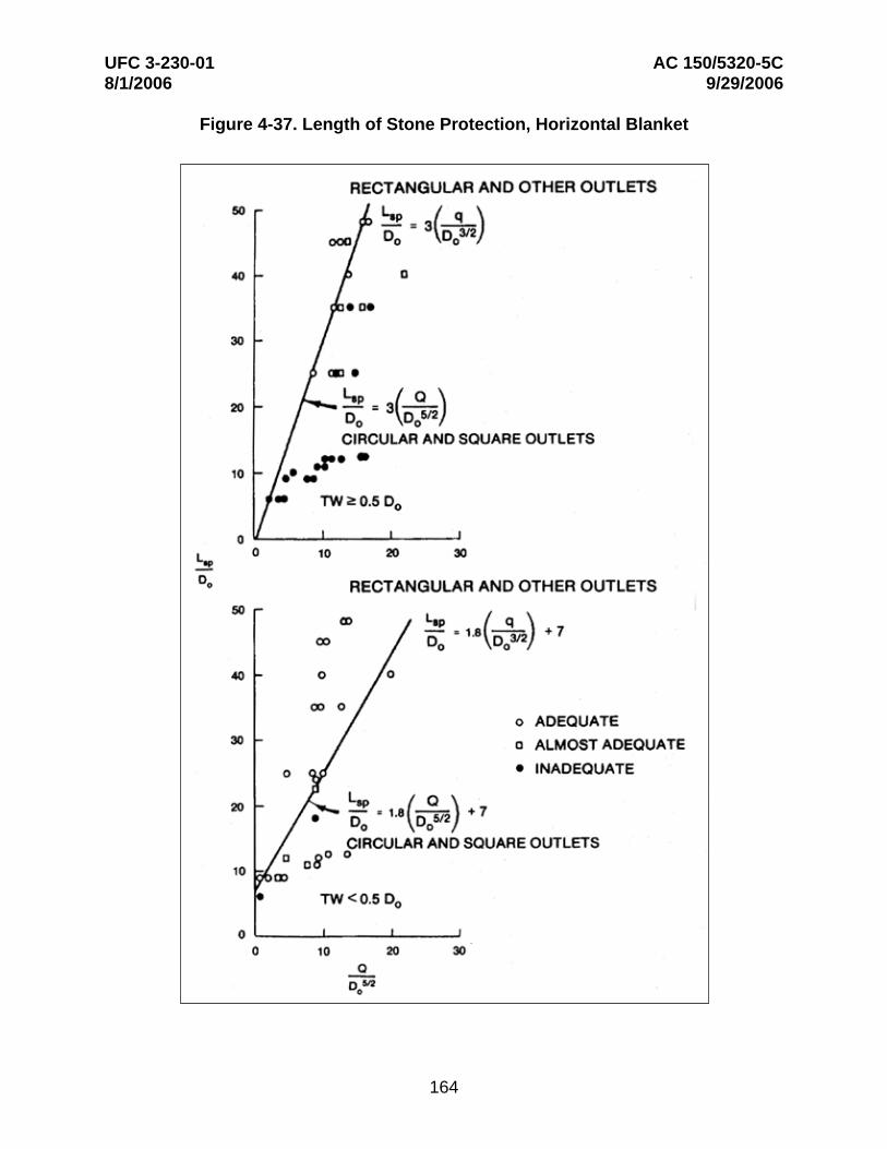
Figure 4-38. Recommended Configuration of Riprap Blanket Subject to Minimum and Maximum Tailwaters
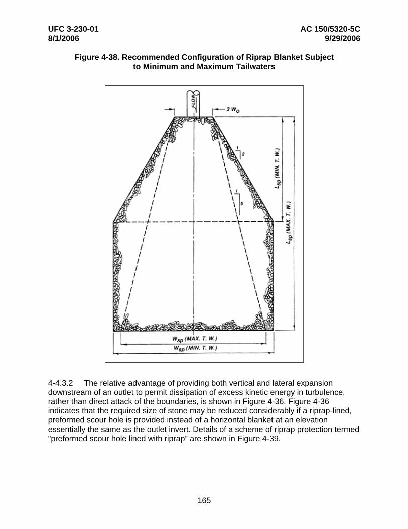
4-4.3.2 The relative advantage of providing both vertical and lateral expansion downstream of an outlet to permit dissipation of excess kinetic energy in turbulence, rather than direct attack of the boundaries, is shown in Figure 4-36. Figure 4-36 indicates that the required size of stone may be reduced considerably if a riprap-lined, preformed scour hole is provided instead of a horizontal blanket at an elevation essentially the same as the outlet invert. Details of a scheme of riprap protection termed "preformed scour hole lined with riprap” are shown in Figure 4-39.
165
UFC 3-230-01 AC 150/5320-5C 8/1/2006 9/29/2006
Figure 4-39. Preformed Scour Hole
4-4.3.3 Three ways in which riprap can fail are movement of the individual stones by a combination of velocity and turbulence, movement of the natural bed material through the riprap, resulting in slumping of the blanket, and undercutting and raveling of the riprap by scour at the end of the blanket; therefore, in design, consideration must be given to the selection of adequately sized stone, use of an adequately graded riprap or provision of a filter blanket, and proper treatment of the end of the blanket.
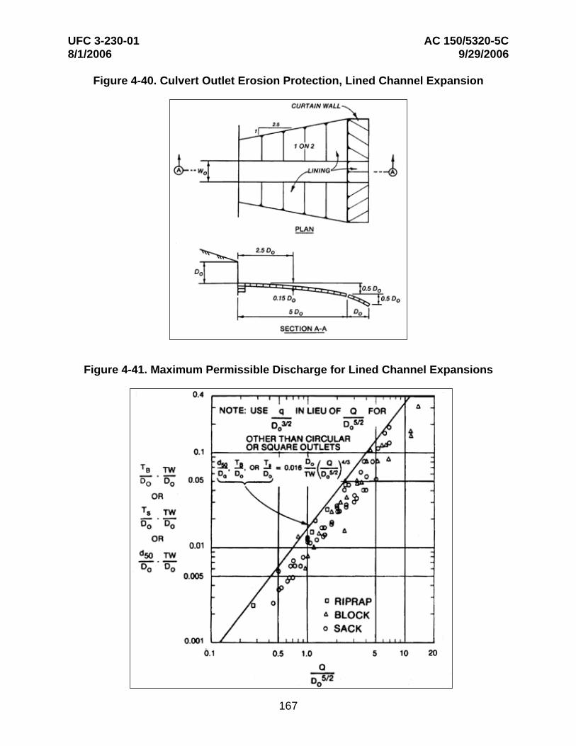
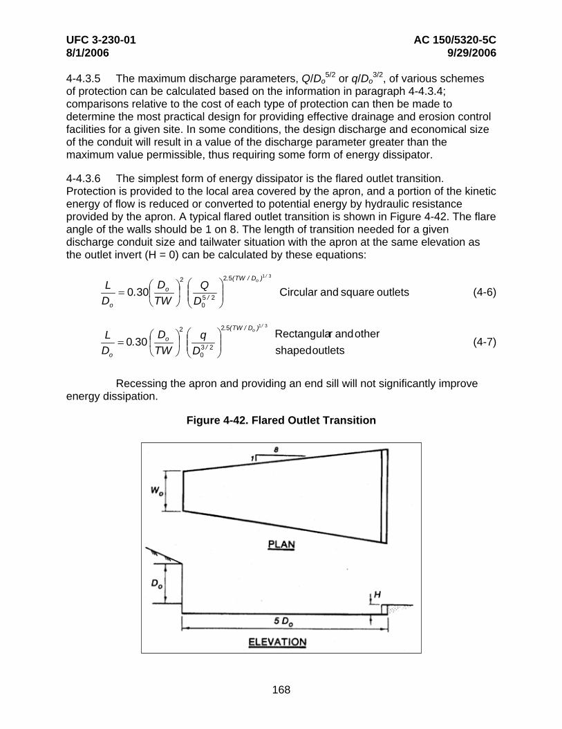
4-4.3.4 Expanding and lining the channel downstream from a square or rectangular outlet for erosion control is usually accomplished using rip rap as shown in Figure 4-40. Figure 4-41 can be used to determine the thickness of the riprap lining. The effectiveness of the lined channel expansion relative to the other schemes of riprap protection described previously is shown in Figure 4-36.
166
UFC 3-230-01 AC 150/5320-5C 8/1/2006 9/29/2006
Figure 4-40. Culvert Outlet Erosion Protection, Lined Channel Expansion
Figure 4-41. Maximum Permissible Discharge for Lined Channel Expansions
167
UFC 3-230-01 AC 150/5320-5C 8/1/2006 9/29/2006
4-4.3.5 The maximum discharge parameters, Q/Do 5/2 or q/Do
3/2, of various schemes of protection can be calculated based on the information in paragraph 4-4.3.4; comparisons relative to the cost of each type of protection can then be made to determine the most practical design for providing effective drainage and erosion control facilities for a given site. In some conditions, the design discharge and economical size of the conduit will result in a value of the discharge parameter greater than the maximum value permissible, thus requiring some form of energy dissipator.
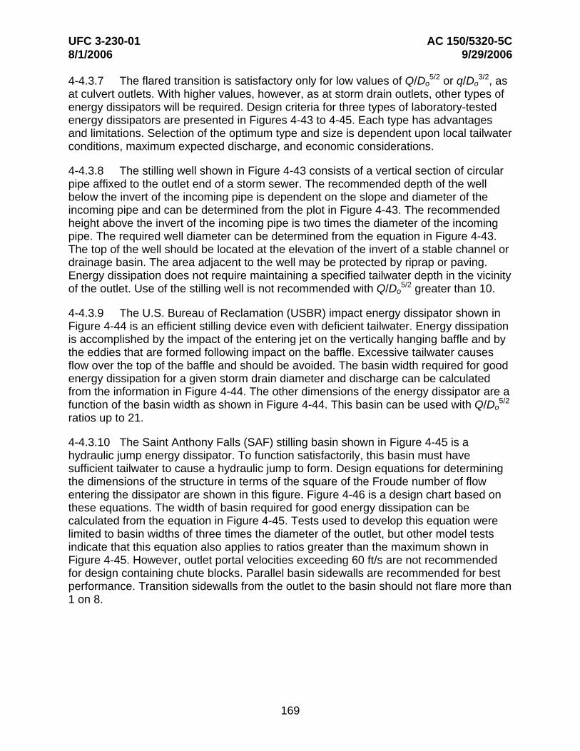
4-4.3.6 The simplest form of energy dissipator is the flared outlet transition. Protection is provided to the local area covered by the apron, and a portion of the kinetic energy of flow is reduced or converted to potential energy by hydraulic resistance provided by the apron. A typical flared outlet transition is shown in Figure 4-42. The flare angle of the walls should be 1 on 8. The length of transition needed for a given discharge conduit size and tailwater situation with the apron at the same elevation as the outlet invert (H = 0) can be calculated by these equations:
2 2.5(TW / D )1 / 3
D ⎜ ⎟
⎜ ⎟
⎛⎜⎝
⎛⎜⎝
⎞
2D ⎞
⎛⎜⎝
⎛⎜⎝
⎞⎟ ⎠
oL Q0.30= Circular and square outlets (4-6)⎟⎠
o 5 / 2D TW D0o
2.5(TW / Do )1 / 3
Rectangular andother⎞⎟ ⎠
L q0.30= (4-7)⎟⎠
o 3 / 2 shapedoutletsDo TW D0
Recessing the apron and providing an end sill will not significantly improve energy dissipation.
Figure 4-42. Flared Outlet Transition
168
UFC 3-230-01 AC 150/5320-5C 8/1/2006 9/29/2006
4-4.3.7 The flared transition is satisfactory only for low values of Q/Do 5/2 or q/Do
3/2, as at culvert outlets. With higher values, however, as at storm drain outlets, other types of energy dissipators will be required. Design criteria for three types of laboratory-tested energy dissipators are presented in Figures 4-43 to 4-45. Each type has advantages and limitations. Selection of the optimum type and size is dependent upon local tailwater conditions, maximum expected discharge, and economic considerations.
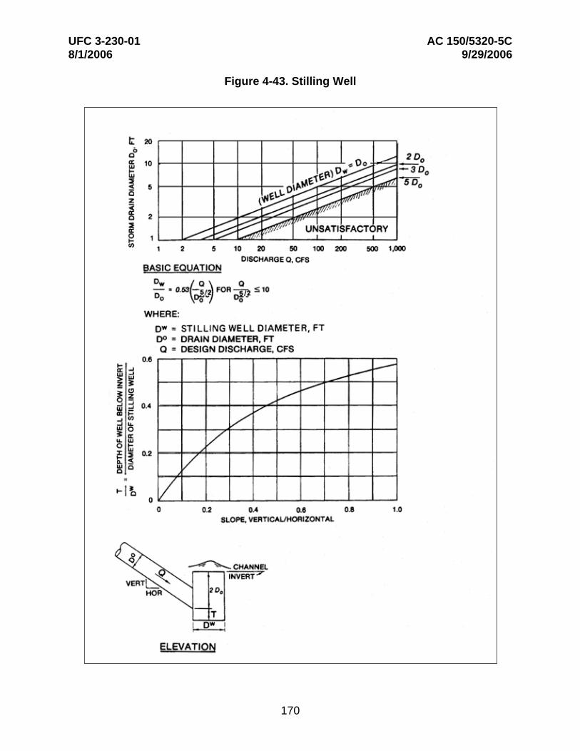
4-4.3.8 The stilling well shown in Figure 4-43 consists of a vertical section of circular pipe affixed to the outlet end of a storm sewer. The recommended depth of the well below the invert of the incoming pipe is dependent on the slope and diameter of the incoming pipe and can be determined from the plot in Figure 4-43. The recommended height above the invert of the incoming pipe is two times the diameter of the incoming pipe. The required well diameter can be determined from the equation in Figure 4-43. The top of the well should be located at the elevation of the invert of a stable channel or drainage basin. The area adjacent to the well may be protected by riprap or paving. Energy dissipation does not require maintaining a specified tailwater depth in the vicinity of the outlet. Use of the stilling well is not recommended with Q/Do
5/2 greater than 10.
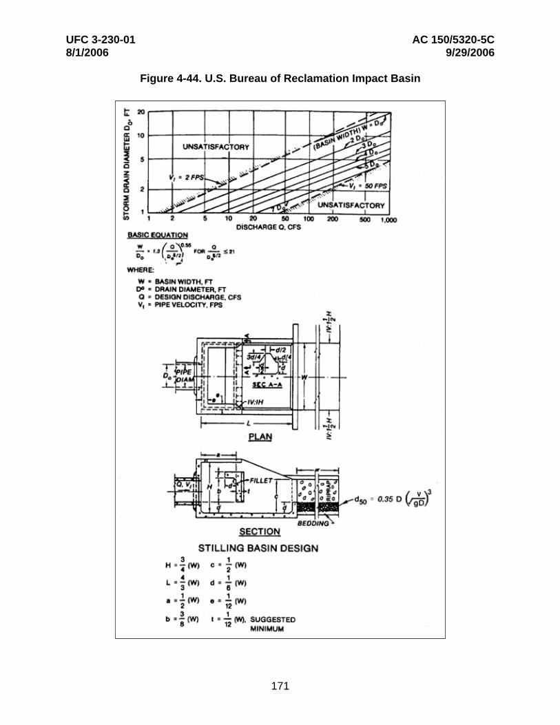
4-4.3.9 The U.S. Bureau of Reclamation (USBR) impact energy dissipator shown in Figure 4-44 is an efficient stilling device even with deficient tailwater. Energy dissipation is accomplished by the impact of the entering jet on the vertically hanging baffle and by the eddies that are formed following impact on the baffle. Excessive tailwater causes flow over the top of the baffle and should be avoided. The basin width required for good energy dissipation for a given storm drain diameter and discharge can be calculated from the information in Figure 4-44. The other dimensions of the energy dissipator are a function of the basin width as shown in Figure 4-44. This basin can be used with Q/Do
5/2
ratios up to 21.
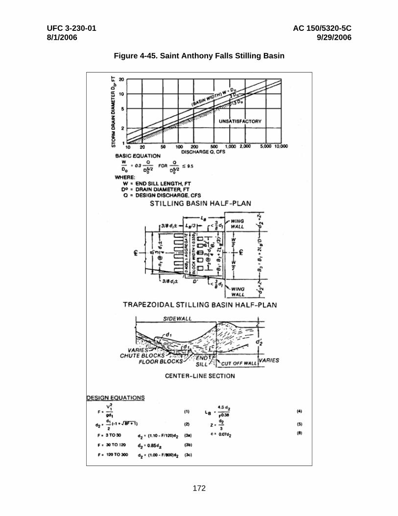
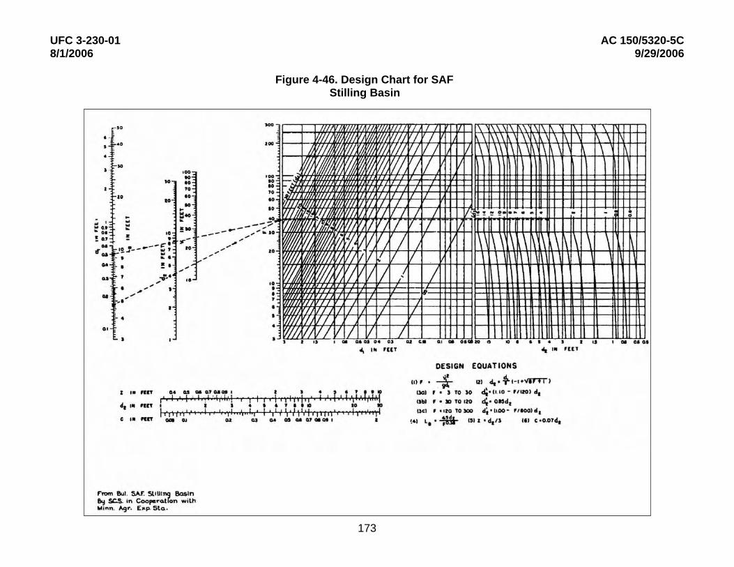
4-4.3.10 The Saint Anthony Falls (SAF) stilling basin shown in Figure 4-45 is a hydraulic jump energy dissipator. To function satisfactorily, this basin must have sufficient tailwater to cause a hydraulic jump to form. Design equations for determining the dimensions of the structure in terms of the square of the Froude number of flow entering the dissipator are shown in this figure. Figure 4-46 is a design chart based on these equations. The width of basin required for good energy dissipation can be calculated from the equation in Figure 4-45. Tests used to develop this equation were limited to basin widths of three times the diameter of the outlet, but other model tests indicate that this equation also applies to ratios greater than the maximum shown in Figure 4-45. However, outlet portal velocities exceeding 60 ft/s are not recommended for design containing chute blocks. Parallel basin sidewalls are recommended for best performance. Transition sidewalls from the outlet to the basin should not flare more than 1 on 8.
169
UFC 3-230-01 AC 150/5320-5C 8/1/2006 9/29/2006
Figure 4-43. Stilling Well
170
UFC 3-230-01 AC 150/5320-5C 8/1/2006 9/29/2006
Figure 4-44. U.S. Bureau of Reclamation Impact Basin
171
UFC 3-230-01 AC 150/5320-5C 8/1/2006 9/29/2006
Figure 4-45. Saint Anthony Falls Stilling Basin
172
UFC 3-230-01 AC 150/5320-5C 8/1/2006 9/29/2006
Figure 4-46. Design Chart for SAF Stilling Basin
173
UFC 3-230-01 AC 150/5320-5C 8/1/2006 9/29/2006
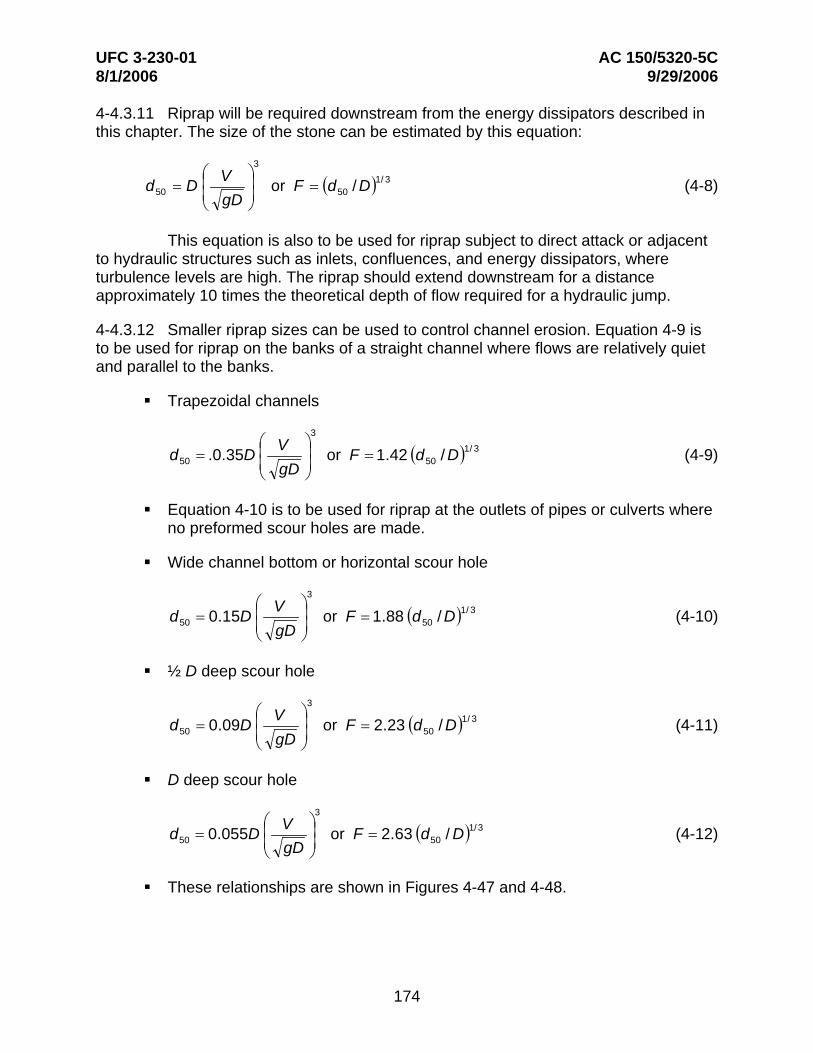
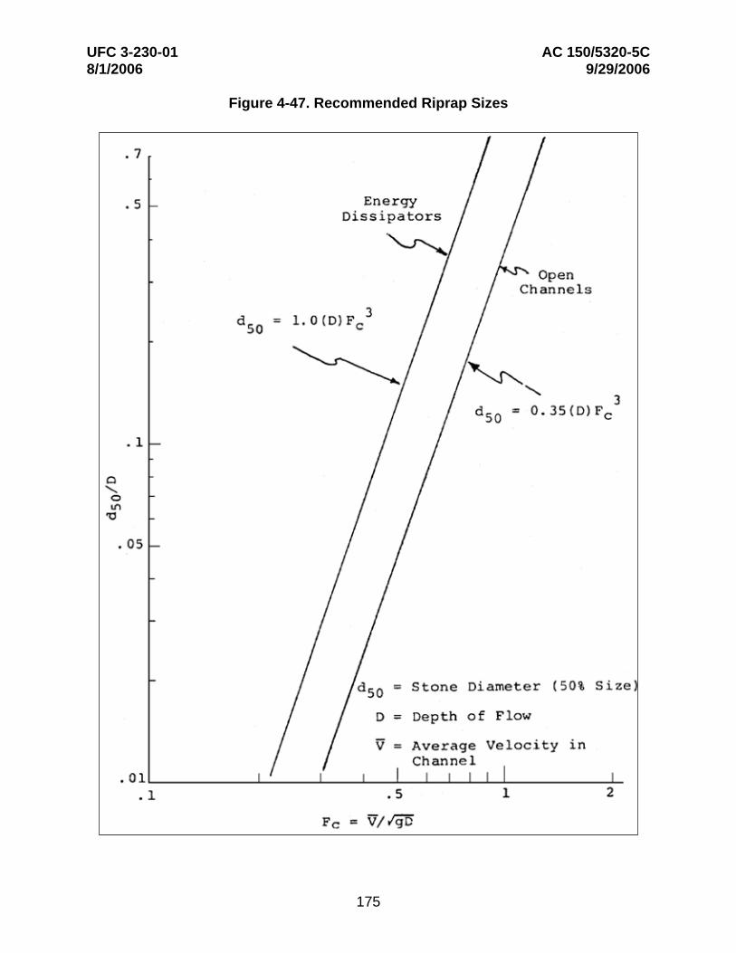
4-4.3.11 Riprap will be required downstream from the energy dissipators described in this chapter. The size of the stone can be estimated by this equation:
3
d50 = D ⎛⎜ V
gD
⎞⎟⎟ or F = (d50 / D)1/ 3 (4-8)⎜⎠⎝
This equation is also to be used for riprap subject to direct attack or adjacent to hydraulic structures such as inlets, confluences, and energy dissipators, where turbulence levels are high. The riprap should extend downstream for a distance approximately 10 times the theoretical depth of flow required for a hydraulic jump.
4-4.3.12 Smaller riprap sizes can be used to control channel erosion. Equation 4-9 is to be used for riprap on the banks of a straight channel where flows are relatively quiet and parallel to the banks.
Trapezoidal channels
3
d50 = .0.35D ⎜⎜⎛ V ⎟
⎟⎞
or F = 1.42 (d50 / D)1/ 3 (4-9)gD ⎠⎝
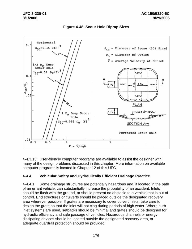
Equation 4-10 is to be used for riprap at the outlets of pipes or culverts where no preformed scour holes are made.
Wide channel bottom or horizontal scour hole
d50 = 0.15D ⎜⎜⎛ V ⎟
⎟⎞
3
or F = 1.88 (d50 / D)1/ 3 (4-10)gD ⎠⎝
½ D deep scour hole
3
d50 = 0.09D ⎛⎜ V
gD
⎞⎟⎟⎠
or F = 2.23 (d50 / D)1/ 3 (4-11)⎜⎝
D deep scour hole
d50 = 0.055D ⎛⎜ V
gD
⎞⎟⎠⎟
3
or F = 2.63 (d50 / D)1/3 (4-12)⎜⎝
These relationships are shown in Figures 4-47 and 4-48.
174
UFC 3-230-01 AC 150/5320-5C 8/1/2006 9/29/2006
Figure 4-47. Recommended Riprap Sizes
175
UFC 3-230-01 AC 150/5320-5C 8/1/2006 9/29/2006
Figure 4-48. Scour Hole Riprap Sizes
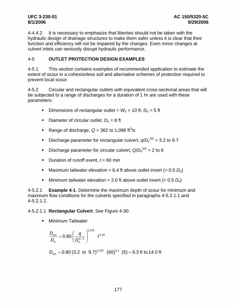
4-4.3.13 User-friendly computer programs are available to assist the designer with many of the design problems discussed in this chapter. More information on available computer programs is located in Chapter 12 of this UFC.
4-4.4 Vehicular Safety and Hydraulically Efficient Drainage Practice
4-4.4.1 Some drainage structures are potentially hazardous and, if located in the path of an errant vehicle, can substantially increase the probability of an accident. Inlets should be flush with the ground, or should present no obstacle to a vehicle that is out of control. End structures or culverts should be placed outside the designated recovery area wherever possible. If grates are necessary to cover culvert inlets, take care to design the grate so that the inlet will not clog during periods of high water. Where curb inlet systems are used, setbacks should be minimal and grates should be designed for hydraulic efficiency and safe passage of vehicles. Hazardous channels or energy dissipating devices should be located outside the designated recovery area, or adequate guardrail protection should be provided.
176
UFC 3-230-01 AC 150/5320-5C 8/1/2006 9/29/2006
4-4.4.2 It is necessary to emphasize that liberties should not be taken with the hydraulic design of drainage structures to make them safer unless it is clear that their function and efficiency will not be impaired by the changes. Even minor changes at culvert inlets can seriously disrupt hydraulic performance.
4-5 OUTLET PROTECTION DESIGN EXAMPLES
4-5.1 This section contains examples of recommended application to estimate the extent of scour in a cohesionless soil and alternative schemes of protection required to prevent local scour.
4-5.2 Circular and rectangular outlets with equivalent cross-sectional areas that will be subjected to a range of discharges for a duration of 1 hr are used with these parameters:
Dimensions of rectangular outlet = Wo = 10 ft, Do = 5 ft
Diameter of circular outlet, Do = 8 ft
Range of discharge, Q = 362 to 1,086 ft3/s
Discharge parameter for rectangular culvert, q/Do 3/2 = 3.2 to 9.7
Discharge parameter for circular culvert, Q/Do 5/2 = 2 to 6
Duration of runoff event, t = 60 min
Maximum tailwater elevation = 6.4 ft above outlet invert (> 0.5 Do)
Minimum tailwater elevation = 2.0 ft above outlet invert (< 0.5 Do)
4-5.2.1 Example 4-1. Determine the maximum depth of scour for minimum and maximum flow conditions for the culverts specified in paragraphs 4-5.2.1.1 and 4-5.2.1.2.
4-5.2.1.1 Rectangular Culvert. See Figure 4-30.
Minimum Tailwater
0.375Dsm = 0.80 ⎜⎜
⎛ q 3 / 2 ⎟⎟
⎞ t 0.10
Do ⎝ Do ⎠
D = 0.80 (3.2 to 9.7)0.375 (60)0.1 (5) = 9.3 ft to 14.0 ftsm
177
UFC 3-230-01 AC 150/5320-5C 8/1/2006 9/29/2006
Maximum Tailwater
0.375Dsm = 0.74 ⎜⎜
⎛ q 3 / 2 ⎟⎟
⎞ t 0.10
Do ⎝ Do ⎠
Dsm = 0.74 (3.2 to 9.7)0.375 (60)0.1 (5) = 8.6 ft to 13.0 ft
4-5.2.1.2 Circular Culvert. See Figure 4-30.
Minimum Tailwater
0.375Dsm ⎛ Q ⎞ 0.10= 0.80 ⎜⎜ 5 / 2 ⎟⎟ tDo ⎝ Do ⎠
Dsm = 0.80 (2 to 6)0.375 (60)0.1 (8) = 12.5 ft to 18.9 ft
Maximum Tailwater
0.375Dsm = 0.74
⎛⎜⎜
q 5 / 2
⎞⎟⎟ t 0.1
Do ⎝ Do ⎠
Dsm = 0.74 (2 to 6)0.375 (60)0.1 (8) = 11.6 ft to 17.5 ft
4-5.2.2 Example 4-2. Determine the maximum width of scour for minimum and maximum flow conditions for the culverts specified in paragraphs 4-5.2.2.1 and 4-5.2.2.2.
4-5.2.2.1 Rectangular Culvert. See Figure 4-31.
Minimum Tailwater
0.915Wsm = 1.00 ⎜⎜
⎛ q 3 / 2 ⎟⎟
⎞ t 0.15
Do ⎝ Do ⎠
W = 1.00 (3.2 to 9.7)0.915 (60)0.15 (5) = 27 ft to 74 ftsm
W = W + Wo −
Do = (27 to 74) + 10
− 5 = 29.5 ft to 76.5 ftsmr sm 2 2 2 2
178
UFC 3-230-01 AC 150/5320-5C 8/1/2006 9/29/2006
Maximum Tailwater
0.915Wsm = 0.72 ⎜⎜
⎛ q 3 / 2 ⎟⎟
⎞ t 0.15
Do ⎝ Do ⎠
W = 0.72 (3.2 to 9.7)0.915 (60)0.015 = 19 ft to 53 ftsm
W D 10 5W = W + o − o = (19 to 53) + − = 21.5 ft to 55.5 ftsmr sm 2 2 2 2
4-5.2.2.2 Circular Culvert. See Figure 4-31.
Minimum Tailwater
0.915Wsm ⎛ Q ⎞ 0.15= 1.00 ⎜⎜ 5 / 2 ⎟⎟ tDo ⎝ Do ⎠
Wsm = 1.00 (2 to 6)0.915 (60)0.15 (8) = 28 ft to 76 ft
Maximum Tailwater
0.915Wsm ⎛ Q ⎞ 0.15= 0.72 ⎜⎜ 5 / 2 ⎟⎟ tDo ⎝ Do ⎠
Wsm = 0.72 (2 to 6)0.915 (60)0.15 (8) = 20 ft to 55 ft
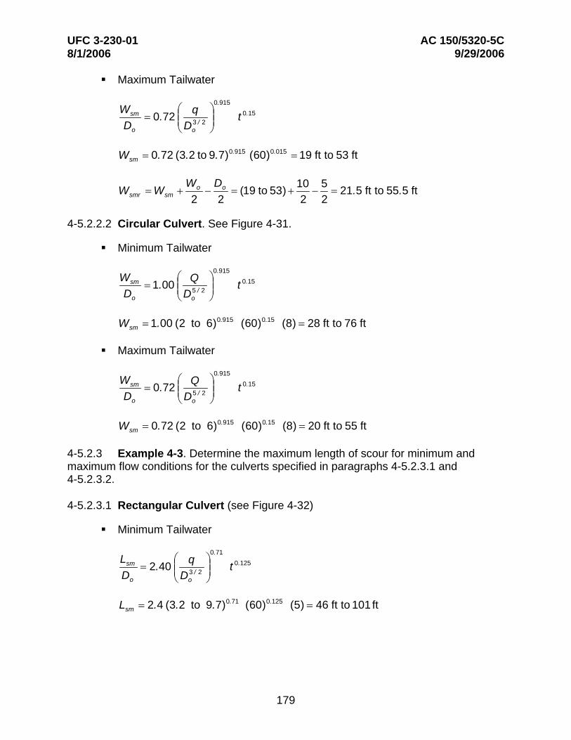
4-5.2.3 Example 4-3. Determine the maximum length of scour for minimum and maximum flow conditions for the culverts specified in paragraphs 4-5.2.3.1 and 4-5.2.3.2.
4-5.2.3.1 Rectangular Culvert (see Figure 4-32)
Minimum Tailwater
0.71Lsm = 2.40
⎛⎜⎜
q 3 / 2
⎞⎟⎟ t 0.125
Do ⎝ Do ⎠
L = 2.4 (3.2 to 9.7)0.71 (60)0.125 (5) = 46 ft to 101 ftsm
179
UFC 3-230-01 AC 150/5320-5C 8/1/2006 9/29/2006
Maximum Tailwater
0.71Lsm = 4.10
⎛⎜⎜
q 3 / 2
⎞⎟⎟ t 0.125
Do ⎝ Do ⎠
Lsm = 4.10 (3.2 to 9.7)0.71 (60)0.125 (5) = 78 ft to 171 ft
4-5.2.3.2 Circular Culvert. See Figure 4-32.
Minimum Tailwater
0.71Lsm ⎛ Q ⎞ 0.125= 2.40 ⎜⎜ 5 / 2 ⎟⎟ tDo ⎝ Do ⎠
Lsm = 2.4 (2 to 6)0.71 (60)0.125 (8) = 52 ft to 114 ft
Maximum Tailwater
0.71Lsm ⎛ Q ⎞ 0.125= 4.10 ⎜⎜ 5 / 2 ⎟⎟ tDo ⎝ Do ⎠
Lsm = 4.10 (2 to 6)0.71 (60)0.125 (8) = 90 ft to 195 ft
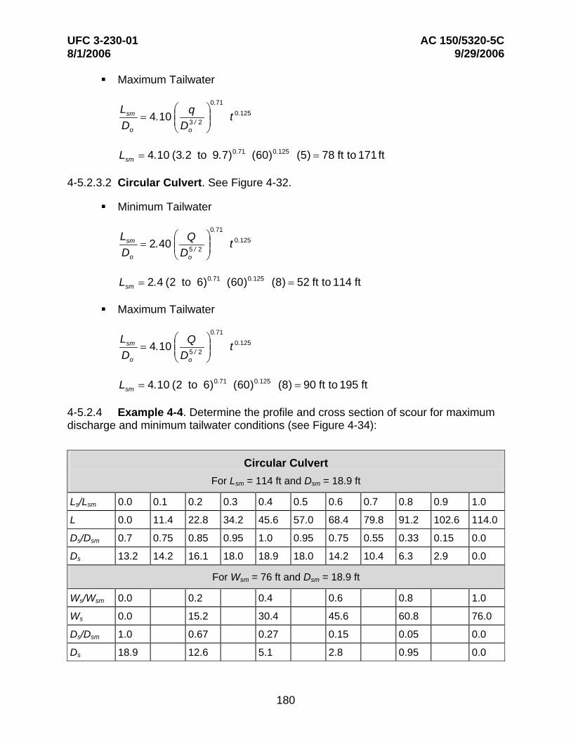
4-5.2.4 Example 4-4. Determine the profile and cross section of scour for maximum discharge and minimum tailwater conditions (see Figure 4-34):
Circular Culvert For Lsm = 114 ft and Dsm = 18.9 ft
Ls/Lsm 0.0 0.1 0.2 0.3 0.4 0.5 0.6 0.7 0.8 0.9 1.0
L 0.0 11.4 22.8 34.2 45.6 57.0 68.4 79.8 91.2 102.6 114.0
Ds/Dsm 0.7 0.75 0.85 0.95 1.0 0.95 0.75 0.55 0.33 0.15 0.0
Ds 13.2 14.2 16.1 18.0 18.9 18.0 14.2 10.4 6.3 2.9 0.0
For Wsm = 76 ft and Dsm = 18.9 ft
Ws/Wsm 0.0 0.2 0.4 0.6 0.8 1.0
Ws 0.0 15.2 30.4 45.6 60.8 76.0
Ds/Dsm 1.0 0.67 0.27 0.15 0.05 0.0
Ds 18.9 12.6 5.1 2.8 0.95 0.0
180
UFC 3-230-01 AC 150/5320-5C 8/1/2006 9/29/2006
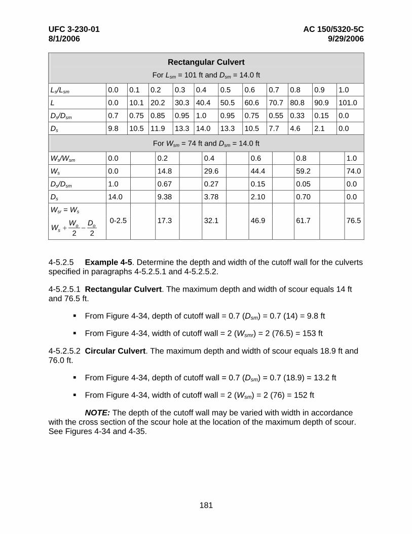
Rectangular Culvert For Lsm = 101 ft and Dsm = 14.0 ft
Ls/Lsm 0.0 0.1 0.2 0.3 0.4 0.5 0.6 0.7 0.8 0.9 1.0
L 0.0 10.1 20.2 30.3 40.4 50.5 60.6 70.7 80.8 90.9 101.0
Ds/Dsm 0.7 0.75 0.85 0.95 1.0 0.95 0.75 0.55 0.33 0.15 0.0
Ds 9.8 10.5 11.9 13.3 14.0 13.3 10.5 7.7 4.6 2.1 0.0
For Wsm = 74 ft and Dsm = 14.0 ft
Ws/Wsm 0.0 0.2 0.4 0.6 0.8 1.0
Ws 0.0 14.8 29.6 44.4 59.2 74.0
Ds/Dsm 1.0 0.67 0.27 0.15 0.05 0.0
Ds 14.0 9.38 3.78 2.10 0.70 0.0
Wsr = Ws
22 oo
s DWW −+
0-2.5 17.3 32.1 46.9 61.7 76.5
4-5.2.5 Example 4-5. Determine the depth and width of the cutoff wall for the culverts specified in paragraphs 4-5.2.5.1 and 4-5.2.5.2.
4-5.2.5.1 Rectangular Culvert. The maximum depth and width of scour equals 14 ft and 76.5 ft.
From Figure 4-34, depth of cutoff wall = 0.7 (Dsm) = 0.7 (14) = 9.8 ft
From Figure 4-34, width of cutoff wall = 2 (Wsmr) = 2 (76.5) = 153 ft
4-5.2.5.2 Circular Culvert. The maximum depth and width of scour equals 18.9 ft and 76.0 ft.
From Figure 4-34, depth of cutoff wall = 0.7 (Dsm) = 0.7 (18.9) = 13.2 ft
From Figure 4-34, width of cutoff wall = 2 (Wsm) = 2 (76) = 152 ft
NOTE: The depth of the cutoff wall may be varied with width in accordance with the cross section of the scour hole at the location of the maximum depth of scour. See Figures 4-34 and 4-35.
181
UFC 3-230-01 AC 150/5320-5C 8/1/2006 9/29/2006
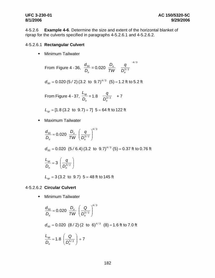
4-5.2.6 Example 4-6. Determine the size and extent of the horizontal blanket of riprap for the culverts specified in paragraphs 4-5.2.6.1 and 4-5.2.6.2.
4-5.2.6.1 Rectangular Culvert
Minimum Tailwater
From Figure 4 - 36, d50 = 0.020
Do q 3 / 2
4 / 3
D TW Do o
d50 = 0.020 (5 / 2) (3.2 to 9.7)4 / 3 (5) = 1.2 ft to 5.2 ft
Lsp qFrom Figure 4 - 37, = 1.8 3 / 2 + 7
D Do o
Lsp = [1.8 (3.2 to 9.7) + 7] 5 = 64 ft to 122 ft
Maximum Tailwater
d50 = 0.020 Do ⎛ q ⎞4 / 3
⎜⎜ 3 / 2 ⎟⎟Do TW ⎝ Do ⎠
d50 = 0.020 (5 / 6.4) (3.2 to 9.7)4 / 3 (5) = 0.37 ft to 0.76 ft
spLDo
= 3 ⎜⎜⎛
⎝ Do
q 3 / 2 ⎟⎟
⎞
⎠
Lsp = 3 (3.2 to 9.7) 5 = 48 ft to 145 ft
4-5.2.6.2 Circular Culvert
Minimum Tailwater
d50 = 0.020 Do ⎛ Q ⎞4 / 3
⎜⎜ 5 / 2 ⎟⎟Do TW ⎝ Do ⎠
d50 = 0.020 (8 / 2) (2 to 6)4 / 3 (8) = 1.6 ft to 7.0 ft
L ⎛ ⎞sp = 1.8 ⎜⎜ Q
⎟⎟ + 7 Do ⎝ Do
5 / 2 ⎠
182
UFC 3-230-01 AC 150/5320-5C 8/1/2006 9/29/2006
L = 1.8 (2 to 6) + 7 8 = 85 ft to 142 ftsp
Maximum Tailwater
d50 Do ⎛ Q ⎞4 / 3
= 0.020 ⎜⎜ 5 / 2 ⎟⎟Do TW ⎝ Do ⎠
d50 = 0.020 (8 / 6.4) (2 to 6)4 / 3 (8) = 0.50 ft to 2.18 ft
Lsp ⎛ Q ⎞= 3 ⎜⎜ 5 / 2 ⎟⎟Do ⎝ Do ⎠
Lsp = 3 (2 to 6) 8 = 48 ft to 144 ft
Use Figure 4-38 to determine the recommended configuration of a horizontal blanket of riprap subject to minimum and maximum tailwaters.
4-5.2.7 Example 4-7. Determine the size and geometry of riprap-lined preformed scour holes 0.5- and 1.0-Do deep for minimum tailwater conditions for the culverts specified in paragraphs 4-5.2.7.1 and 4-5.2.7.2.
4-5.2.7.1 Rectangular Culvert. See Figure 4-36.
0.5-Do-Deep Riprap-Lined Preformed Scour Hole
d D ⎛ ⎞4 / 3
50 = 0.0125 o ⎜⎜
q 3 / 2 ⎟⎟Do TW ⎝ Do ⎠
d50 = 0.0125 (5 / 2) (3.2 to 9.7)4 / 3 (5) = 0.73 ft to 3.2 ft
1.0-Do-Deep Riprap-Lined Preformed Scour Hole
d D ⎛ q ⎞4 / 3
50 o= 0.0082 ⎜⎜ 3 / 2 ⎟⎟Do TW ⎝ Do ⎠
d50 = 0.0082 (5 / 2) (3.2 to 9.7)4 / 3 (5) = 0.48 ft to 2.1ft
183
UFC 3-230-01 AC 150/5320-5C 8/1/2006 9/29/2006
4-5.2.7.2 Circular Culvert
0.5-Do-Deep Riprap-Lined Preformed Scour Hole
d50 = 0.0125 Do ⎛⎜⎜
Q ⎞⎟⎟
4 / 3
Do TW ⎝ Do 5 / 2
⎠
d50 = 0.0125 (8 / 2) (2 to 6)4 / 3 (8) = 1.0 ft to 4.4 ft
1.0-Do-Deep Riprap-Lined Preformed Scour Hole
d D ⎛ Q ⎞4 / 3
50 o
Do
= 0.0082 TW ⎝
⎜⎜ Do 5 / 2
⎠⎟⎟
d50 = 0.0082 (8 / 2) (2 to 6)4 / 3 (8) = 0.66 ft to 2.9 ft
See Figure 4-24 for geometry.
4-5.2.8 Example 4-8. Determine the size and geometry of a riprap-lined channel expansion for minimum tailwaters for the culverts specified in paragraphs 4-5.2.8.1 and 4-5.2.8.2 (see Figure 4-41).
4-5.2.8.1 Rectangular Culvert
d D ⎛ q ⎞4 / 3
50 o
Do
= 0.016 TW ⎝
⎜⎜ Do 3 / 2
⎠⎟⎟
d50 = 0.016 (5 / 2) (3.2 to 9.7)4 / 3 (5) = 0.94 ft to 4.1ft
4-5.2.8.2 Circular Culvert
d D ⎛ Q ⎞4 / 3
50 o
Do
= 0.016 TW ⎝
⎜⎜ Do 5 / 2
⎠⎟⎟
d50 = 0.016 (8 / 2) (2 to 6)4 / 3 (8) = 1.29 ft to 5.6 ft
See Figure 4-40 for geometry.
4-5.2.9 Example 4-9. Determine the length and geometry of a flared outlet transition for minimum tailwaters for the culverts specified in paragraphs 4-5.2.9.1 and 4-5.2.9.2.
184
UFC 3-230-01 AC 150/5320-5C 8/1/2006 9/29/2006
4-5.2.9.1 Rectangular Culvert
L = 0.30 ⎜⎛
Do ⎟⎞
2
⎜⎜⎛ q
3 / 2 ⎟⎟⎞
2.5(TW / Do )1/ 3
Do ⎝TW ⎠ ⎝ Do ⎠
L = 0.3 (5 / 2)2 (3.2 to 9.7)2.5( 2 / 5 )1 / 3
5 = 80 ft to 616 ft
4-5.2.9.2 Circular Culvert
L ⎢⎡ ⎛ D ⎞
2 ⎛ Q ⎞2.5(TW / Do )1 / 3
⎥⎤
o= 0.30 ⎜ ⎟ ⎜⎜ 5 / 2 ⎟⎟ D ⎢ TW D ⎥o ⎣ ⎝ ⎠ ⎝ o ⎠ ⎦
2 2.5( 2 / 8 )1 / 3
L = [ 0.3 (8 / 2) (2 to 6) ] 8 = 114 ft to 645 ft
See Figure 4-42 for geometric details. These equations were developed for H equals 0 or horizontal apron at outlet invert elevation without an end sill.
4-5.2.10 Example 4-10. Determine the diameter of the stilling well required downstream of the 8-ft-diameter outlet:
From Figure 4-43:
1.0DW ⎛ Q ⎞
= 0.53 ⎜⎜ 5 / 2 ⎟⎟Do ⎝ Do ⎠
DW = 0.53 (2 to 6) 8 = 8.5 ft to 25.4 ft
See Figure 4-43 for additional dimensions.
4-5.2.11 Example 4-11. Determine the width of a USBR Type VI basin required downstream of the 8-ft-diameter outlet:
From Figure 4-44:
0.55WVI ⎛ Q ⎞
= 1.30 ⎜⎜ 5 / 2 ⎟⎟Do ⎝ Do ⎠
0.55WVI = [ 1.3 (2 to 6) ] 8 = 15.2 ft to 27.9 ft
185
UFC 3-230-01 AC 150/5320-5C 8/1/2006 9/29/2006
See Figure 4-44 for additional dimensions.
4-5.2.12 Example 4-12. Determine the width of the SAF basin required downstream of the 8-ft-diameter outlet:
From Figure 4-45:
1.0WSAF ⎛ ⎞
= 0.30 ⎜⎜ Q
⎟⎟ D D5 / 2 o ⎝ o ⎠
WSAF = 0.30 (2 to 6) 8 = 4.8 ft to 14.4 ft
See Figure 4-45 for additional dimensions.
4-5.2.13 Example 4-13. Determine the size of riprap required downstream of an 8-ft-diameter culvert and a 14.4-ft-wide SAF basin with a discharge of 1,086 ft3/s:
q = Q
= 1086
= 75 ft3 /s/ftWSAF 14.4
V1 = Q
= 1086
2 = 21.6 ft/sA 0.785(8)
d1 = q
= 75
= 3.5 ft V1 21.6
d2 = 8.4 ft (from conjugate depth relations)
Minimum Tailwater Required For A Hydraulic Jump = 0.90 (8.4) = 7.6 ft
3
d50 = D ⎜⎛⎜ V ⎞
⎟ gD ⎟⎠⎝
V = q =
75 = 9.9 ft/s
D 7.6
⎡ 9.9 ⎤3
d50 = 1.0 ⎢ ⎥ 7.6⎢ 32.2 (7.6) ⎥⎦⎣
d50 = 1.9 ft
186