Embed Size (px)
Citation preview
UFC 3-610-01N 16 January 2004
UNIFIED FACILITIES CRITERIA (UFC)
ADMINITRATIVE FACILITIES
APPROVED FOR PUBLIC RELEASE; DISTRIBUTION UNLIMITED
CANCELLED
UFC 3-610-01N 16 January 2004
UNIFIED FACILITIES CRITERIA (UFC)
ADMINISTRATIVE FACILITIES
Any copyrighted material included in this UFC is identified at its point of use. Use of the copyrighted material apart from this UFC must have the permission of the copyright holder. U.S. ARMY CORPS OF ENGINEERS NAVAL FACILITIES ENGINEERING COMMAND (Preparing Activity) AIR FORCE CIVIL ENGINEER SUPPORT AGENCY Record of Changes (changes are indicated by \1\ ... /1/) Change No. Date Location
This UFC supersedes Military Handbook 1034, dated March 1988.
CANCELLED
UFC 3-610-01N 16 January 2004
FOREWORD \1\ The Unified Facilities Criteria (UFC) system is prescribed by MIL-STD 3007 and provides planning, design, construction, sustainment, restoration, and modernization criteria, and applies to the Military Departments, the Defense Agencies, and the DoD Field Activities in accordance with USD(AT&L) Memorandum dated 29 May 2002. UFC will be used for all DoD projects and work for other customers where appropriate. All construction outside of the United States is also governed by Status of forces Agreements (SOFA), Host Nation Funded Construction Agreements (HNFA), and in some instances, Bilateral Infrastructure Agreements (BIA.) Therefore, the acquisition team must ensure compliance with the more stringent of the UFC, the SOFA, the HNFA, and the BIA, as applicable. UFC are living documents and will be periodically reviewed, updated, and made available to users as part of the Services’ responsibility for providing technical criteria for military construction. Headquarters, U.S. Army Corps of Engineers (HQUSACE), Naval Facilities Engineering Command (NAVFAC), and Air Force Civil Engineer Support Agency (AFCESA) are responsible for administration of the UFC system. Defense agencies should contact the preparing service for document interpretation and improvements. Technical content of UFC is the responsibility of the cognizant DoD working group. Recommended changes with supporting rationale should be sent to the respective service proponent office by the following electronic form: Criteria Change Request (CCR). The form is also accessible from the Internet sites listed below. UFC are effective upon issuance and are distributed only in electronic media from the following source: • Whole Building Design Guide web site http://dod.wbdg.org/. Hard copies of UFC printed from electronic media should be checked against the current electronic version prior to use to ensure that they are current. /1/ AUTHORIZED BY: ______________________________________ DONALD L. BASHAM, P.E. Chief, Engineering and Construction U.S. Army Corps of Engineers
______________________________________DR. JAMES W WRIGHT, P.E. Chief Engineer Naval Facilities Engineering Command
______________________________________ KATHLEEN I. FERGUSON, P.E. The Deputy Civil Engineer DCS/Installations & Logistics Department of the Air Force
______________________________________Dr. GET W. MOY, P.E. Director, Installations Requirements and Management Office of the Deputy Under Secretary of Defense (Installations and Environment)
CANCELLED
UFC 4-610-01 16 January 2004
i
CONTENTS
Page CHAPTER 1 INTRODUCTION Paragraph 1-1 PURPOSE AND SCOPE ....................................................... 1-1
1-2 APPLICABILITY..................................................................... 1-1 1-2.1 General Building Requirements ............................................. 1-1 1-2.2 Safety .................................................................................... 1-1 1-2.3 Fire Protection ....................................................................... 1-1 1-2.4 Antiterrorism/Force Protection ............................................... 1-1 1-3 REFERENCES ...................................................................... 1-1
APPENDIX A MIL-HDBK 1034……...…………...................…………………… A-1
CANCELLED
UFC 4-610-01 16 January 2004
1-1
CHAPTER 1
INTRODUCTION 1-1 PURPOSE AND SCOPE. This UFC is comprised of two sections. Chapter 1 introduces this UFC and provides a listing of references to other Tri-Service documents closely related to the subject. Appendix A contains the full text copy of the previously released Military Handbook (MIL-HDBK) on this subject. This UFC serves as criteria until such time as the full text UFC is developed from the MIL-HDBK and other sources.
This UFC provides general criteria for the design of administrative facilities.
Note that this document does not constitute a detailed technical design, maintenance or operations manual, and is issued as a general guide to the considerations associated with the design of administrative facilities. 1-2 APPLICABILITY. This UFC applies to all DoD agencies and contractors preparing designs of administrative facilities. 1-2.1 GENERAL BUILDING REQUIREMENTS. All DoD facilities must comply with UFC 1-200-01, Design: General Building Requirements. If any conflict occurs between this UFC and UFC 1-200-01, the requirements of UFC 1-200-01 take precedence. 1-2.2 SAFETY. All DoD facilities must comply with DODINST 6055.1 and applicable Occupational Safety and Health Administration (OSHA) safety and health standards. NOTE: All NAVY projects, must comply with OPNAVINST 5100.23 (series), Navy Occupational Safety and Health Program Manual. The most recent publication in this series can be accessed at the NAVFAC Safety web site: www.navfac.navy.mil/safety/pub.htm. If any conflict occurs between this UFC and OPNAVINST 5100.23, the requirements of OPNAVINST 5100.23 take precedence. 1-2.3 FIRE PROTECTION. All DoD facilities must comply with UFC 3-600-01, Design: Fire Protection Engineering for Facilities. If any conflict occurs between this UFC and UFC 3-600-01, the requirements of UFC 3-600-01 take precedence. 1-2.4 ANTITERRORISM/FORCE PROTECTION. All DoD facilities must comply with UFC 4-010-01, Design: DoD Minimum Antiterrorism Standards for Buildings. If any conflict occurs between this UFC and UFC 4-010-01, the requirements of UFC 4-010-01 take precedence. 1-3 REFERENCES. The following Tri-Service publications have valuable information on the subject of this UFC. When the full text UFC is developed for this subject, applicable portions of these documents will be incorporated into the text. The
CANCELLED

UFC 4-610-01 16 January 2004
1-1
designer is encouraged to access and review these documents as well as the references cited in Appendix A.
CANCELLED

UFC 4-610-01 16 January 2004
A-1
APPENDIX A
MIL-HDBK 1034 ADMINISTRATIVE FACILITIES
CANCELLED
MIL-HDBK-1034
MIL-HDBK-1034NOTICE 131 MARCH 1988
MILITARY HANDBOOK
ADMINISTRATIVE FACILITIES
TO ALL HOLDERS OF MIL-HDBK-1034:
1. THE FOLLOWING PAGES OF MIL-HDBK-1034 HAVE BEEN REVISED ANDSUPERSEDE THE PAGES LISTED:
NEW PAGE DATE SUPERSEDED PAGE DATE56
REPRINTED WITHOUT CHANGE31 MAR 88 6 OCT 87
2. RETAIN THIS NOTICE AND INSERT BEFORE TABLE OF CONTENTS.
3. Holders of MIL-HDBK-1034 will verify that all changes indicatedabove have been made. This notice page will be retained as a checksheet. This issuance, together with appended pages, is a separatepublication. Each notice is to be retained by stocking points untilthe Military Handbook is completely revised or cancelled.
CUSTODIANS: PREPARING ACTIVITY:NAVY-YD NAVY-YD
PROJECT NO. 0241
DISTRIBUTION STATEMENT A. Approved for public release; distribution
is unlimited.
AREA FACR
CANCELLED
MIL-HDBK-1034
2.4.10.7 Color Application. A conservative approach to color is best forsmall enclosed spaces, such as interior offices. Too much intense hue willpsychologically tire an occupant quickly.
2.4.10.8 Value and Intensity of Hue. Value and intensity of hue play crucialroles in the specification of color. The lighter, more pastel, and neutralvalues provide better design solutions for background areas of floors, walls,and ceilings. Neutral colors are less inhibitive when used in materials andfurnishings. They reflect light better, provide an open expansion to thespace, and support the use of deep value accents or patterned materials.
2.4.10.9 Strong Colors. Strong colors, if used too extensively on one sideof a room, create a spatial imbalance.
2.4.10.10 Pale Pastel Colors. Pale, pastel colors make walls look light,contributing to a feeling of openness. In a small room, walls can be made toseem to recede by painting them in light values of cool colors such as greenor blue. Saturated colors absorb a great deal of light, contributing to asense of heaviness.
2.4.10.11 Principles of Spatial Manipulation. The following statements areprinciples of spatial manipulation through the use of color:
a) Dark ceilings will visually lower the apparent height of a room.
b) Dark or strong-valued ceilings and floors will jointly unify aspace.
c) Light ceilings will visually increase the apparent height of aroom, while light walls will expand a space.
d) Strong color on an end wall will visually shorten the length ofa room. Conversely, cool colors will recede a plane.
e) Strong color on a wall will call attention to itself.
f) A brightly colored wall will appear larger than it actually is,because the retina is more actively stimulated than with a greyed hue.
g) A light wall will emphasize dark objects placed in front of it.
h) A dark wall will make light colors or tints appear brighter.
i) Color can direct movement through a space: in furnishings, ingraphics, or through the relationship of colors between surrounding andadjoining spaces.
j) Light objects will appear larger in dimension against a whitebackground.
k) In order to balance light and dark areas in relation to oneanother, light areas should be smaller in size than dark areas.
REPRINTED WITHOUT CHANGE
CANCELLED

MIL-HDBK-1034
l) Strong color, coupled with texture, can camouflage undesirablearchitectural elements.
m) Colors affect and modify one another. Therefore, it isnecessary to give careful consideration to the effects of one color on another.
o) Colors of deep value in too great a quantity will make the wallsof a room appear heavy; pale colors will impart a feeling of lightness andexpansion.
2.4.11 Signage. A sign system shall be provided for direction,identification, and regulation of spaces. Both interior and exterior signsshall be included to orient, direct, and control pedestrian and vehiculartraffic (refer to NAVFAC NFGS-10440, Signs).
2.4.12 Vending/Cafeteria Area. The Randolph Sheppard Act requires that aninvitation be given to blind vendors to establish a vending or cafeteria areawithin the building.
2.4.13 Access for the Physically Handicapped. The building shall bedesigned to ensure accessibility for the physically handicapped in accordancewith the Uniform Federal Accessibility Standards, Federal Register, Vol. 49,No. 153, August 7, 1984, and MIL-HDBK-1190.
2.4.14 Security. Identify all areas requiring physical security with theuser agency of the specific administration facility; security provisions shallbe in compliance with MIL-HDBK-1013/1, Physical Security. Some areas inadministration buildings have special requirements for excluding unauthorizedpersonnel and for protecting Government property and classified information.Coordinate with the project sponsor to obtain applicable securityrequirements. General requirements for physical security are included inOPNAVINST 5530.14A, Physical Security and Loss Prevention Manual, Office ofthe Chief of Naval Operations, 16 September 1985. OPNAVINST 5510.16,Information and Personnel Security Program Regulations, Office of the Chief ofNaval Operations, shall apply for classified information. All areas’ requiringsecurity measures should be grouped together to facilitate control. Theserestricted areas are classified as follows:
2.4.14.1 Exclusion Area. An exclusion area is an area containing classifiedinformation of such nature that access to the area constitutes, for allpractical purposes, access to classified information.
2.4.14.2 Limited Area. A limited area is defined as an area containingclassified information and in which uncontrolled movement would permit accessto the classified information, but within which access may be prevented byescort and other internal restrictions and controls.
CHANGE 1, MARCH 1988
CANCELLED
MIL-HDBK-1034
ABSTRACT
Design criteria for use by experienced architects and engineers arepresented for facilities covered by Category Class 600. The contents includecriteria for Navy and Marine Corps administration buildings and relatedfacilities. This includes architectural, mechanical, and electricalrequirements; interior systems requirements; electromagnetic compatibilityrequirements; areas housing electronic equipment; TEMPEST requirements; andrequirements for security and restricted areas, plus designs and types offlagstaffs.
iii
CANCELLED

MIL-HDBK-1034
iv
CANCELLED
MIL-HDBK-1034
FOREWORD
This handbook has been developed from an evaluation of facilities in the shoreestablishment, from surveys of the availability of new materials andconstruction methods, and from selection of the best design practices of theNaval Facilities Engineering Command (NAVFACENGCOM), other Governmentagencies, and the private sector. This handbook was prepared using, to themaximum extent feasible, national professional society, association, andinstitute standards. Deviations from these criteria, in the planning,engineering, design, and construction of Naval shore facilites, cannot be madewithout prior approval of NAVFACENGCOM HQ Code 04.
Design cannot remain static any more than the functions it serves or thetechnologies it uses. Accordingly, recommendations for improvement areencouraged and should be furnished to Commander, Naval Facilities EngineeringCommand, Western Division, Code 406C, P.O. Box 727, San Bruno, California94066-0720, telephone commercial (415) 877-7422.
THIS HANDBOOK SHALL NOT BE USED AS A REFERENCE DOCUMENT FOR PROCUREMENT OFFACILITIES CONSTRUCTION. IT IS TO BE USED IN THE PURCHASE OF FACILITIESENGINEERING STUDIES AND DESIGN (FINAL PLANS, SPECIFICATIONS, AND COSTESTIMATES). DO NOT REFERENCE IT IN MILITARY OR FEDERAL SPECIFICATIONS OROTHER PROCUREMENT DOCUMENTS.
CANCELLED
MIL-HDBK-1034
ADMINISTRATIVE FACILITIES CRITERIA MANUALS
CriteriaManual Title
MIL-HDBK-1034 Administrative Facilities WESTDIV
PA
Note: This handbook is issued to provide immediate guidance to the user.However, it may or may not conform to format requirements ofMIL-HDBK-1006/3 and will be corrected on the next update.
vi
CANCELLED
MIL-HDBK-1034
ADMINISTRATIVE FACILITIES
CONTENTS
Page
Section 1 INTRODUCTION1.1 Scope ................................................. 1
1.2 Related Criteria ...................................... 1
1.3 Cancellation .......................................... 1
Section 2 DESIGN/PLANNING CONSIDERATIONS2.1 Predesign Planning ....................................2.1.1 Square Footage Criteria ...............................2.1.2 Expansion .............................................2.1.2.1 Service Core ..........................................2.1.2.2 Short-Term Expansion ..................................2.2 Site Planning .........................................2.2.1 Administration Building ...............................2.2.2 Parking ...............................................2.2.3 Flagstaff .............................................2.3 Design Character ......................................2.4 Design Factors ........................................2.4.1 Reception Area ........................................2.4.2 Lobby Area ............................................2.4.3 Toilets ...............................................2.4.4 Private Offices .......................................2.4.4.1 Command Suite .........................................2.4.4.2 Other Executive Offices ...............................2.4.5 General Offices .......................................2.4.6 Communications Areas ..................................2.4.7 Circulation ...........................................2.4.8 Ancillary Spaces ......................................2.4.9 Building Design and Materials .........................2.4.10 Colors ................................................2.4.10.1 Color Perception ......................................2.4.10.2 Color Properties ......................................2.4.10.3 Cool Colors ...........................................2.4.10.4 Warm Colors ...........................................2.4.10.5 Emotional Responses to Color ..........................2.4.10.6 Mental Responses to Color .............................2.4.10.7 Color Application .....................................2.4.10.8 Value and Intensity of Hue ............................2.4.10.9 Strong Colors .........................................2.4.10.10 Pale Pastel Colors ....................................2.4.10.11 Principles of Spatial Manipulation ....................2.4.11 Signage ...............................................2.4.12 Vending/Cafeteria Area ................................2.4.13 Access for the Physically Handicapped .................2.4.14 Security ..............................................2.4.14.1 Exclusion Area ........................................2.4.14.2 Limited Area ..........................................
2222222223333333333444444444455555666666
vii
CANCELLED
MIL-HDBK-1034
Page
2.4.14.3 Controlled Area ....................................... 72.4.14.4 Restricted Area ....................................... 7
Section 3 BUILDING SYSTEMS REQUIREMENTS3.1 Structural ............................................ 83.2 Civil ................................................. 83.3 Mechanical ............................................ 83.3.1 Plumbing .............................................. 83.3.2 Heating, Ventilation, and Air Conditioning ............ 83.3.2.1 Special Temperature and Humidity Control .............. 83.3.2.2 Smoke Exhaust System .................................. 83.3.2.3 Combustible Materials ................................. 83.3.3 Fire Protection ....................................... 83.4 Electrical ............................................ 83.4.1 Communications ........................................ 83.4.2 Lighting .............................................. 83.4.3 Power Requirements .................................... 93.5 Energy Conservation ................................... 93.5.1 Guidelines ............................................ 93.5.2 Standards ............................................. 93.6 Requirements for Security and Restricted Areas ........ 93.6.1 Vaults ................................................ 93.6.2 Physical Security ..................................... 9
Section 4 INTERIOR SYSTEMS REQUIREMENTS4.1 Space Planning ........................................ 104.1.1 Building Elements ..................................... 104.1.2 Floor Size and Building Configuration................. 104.1.3 Zoning Diagrams ....................................... 104.1.4 Planning Criteria ..................................... 104.2 Space Standards ....................................... 104.2.1 Automated and Conventional Workstations ............... 104.2.1.1 VDT/Keyboard Configuration ............................ 104.2.1.2 Conventional Task Space ............................... 104.2.1.3 Additional Equipment .................................. 144.2.1.4 Special Equipment Requirements ........................ 144.2.2 Shared Equipment ...................................... 144.3 Human Comfort ......................................... 144.3.1 Temperature ........................................... 144.3.1.1 Equipment ............................................. 144.3.1.2 Equipment Distribution ................................ 144.3.1.3 Heat Emission ......................................... 144.3.2 Humidity/Static Control ............................... 144.3.3 Fresh Air ............................................. 144.4 Power, Telephone, Data Distribution ................... 144.4.1 Power ................................................. 144.4.1.1 Poke-Through System ................................... 154.4.1.2 Power Pole System ..................................... 154.4.1.3 Conventional Walls and Columns ........................ 154.4.1.4 Wired Slabs ........................................... 15
viii
CANCELLED
MIL-HDBK-1034
Page
4.4.1.5 Flat Conductor Cable .................................. 154.4.1.6 Raised Floor Systems .................................. 154.4.2 Communications ........................................ 154.4.2.1 Telephone Outlet Boxes ................................ 154.4.2.2 Installation of Communications Systems ................ 154.4.2.3 Interior Telephone Service ............................ 154.4.3 Data .................................................. 154.4.3.1 Distribution of Data Cable ............................ 164.4.3.2 Installation of Local Area Network .................... 16
4.5 Lighting .............................................. 164.5.1 Lighting Design Application ........................... 164.5.1.1 Video Display Terminal (VDT) Area ..................... 164.5.1.2 Reflectance Values .................................... 164.5.1.3 Location of VDT Terminals ............................. 164.5.1.4 Lamps ................................................. 16
4.5.1.5 Maintenance ........................................... 164.5.2 General (Ambient) Lighting ............................ 164.5.2.1 Recessed Ceiling Fixtures (Direct) .................... 164.5.2.2 Baffled Ceiling Fixtures (Direct) ..................... 164.5.2.3 Pendant Ceiling Fixtures (Indirect or Direct) ......... 164.5.2.4 Floor- or Furniture-Mounted Fixtures .................. 194.5.3 Task Lighting ......................................... 19
4.5.4 Accent Lighting ....................................... 19
4.5.5 General Maintained Light Levels ....................... 194.6 Acoustics ............................................. 19
4.6.1 Noise Transfer ........................................ 194.6.2 Acoustically Absorbent Ceilings ....................... 194.6.3 Sound Masking ......................................... 194.6.4 Acoustical Hoods and Isolation Pads ................... 194.7 Materials and Finishes ................................ 194.8 Furnishings ........................................... 194.8.1 Task Requirements ..................................... 214.8.2 Furniture Options ..................................... 214.8.2.1 Conventional Furniture ................................ 214.8.2.2 Systems/Modular Furniture ............................. 214.8.2.3 Combination ........................................... 214.8.3 Seating ............................................... 21
4.8.4 Evaluation of Workstation Design ...................... 224.8.5 Evaluation of Products and Vendors .................... 234.9 Areas Housing Electronic Equipment .................... 234.9.1 General Architectural Requirements .................... 234.9.1.1 Applicability ......................................... 234.9.1.2 Equipment ............................................. 234.9.1.3 Location .............................................. 244.9.2 Construction .......................................... 244.9.2.1 Exterior Walls ........................................ 244.9.2.2 Floors ................................................ 24
4.9.2.3 Windows ............................................... 24
4.9.3 Heating and Ventilating Requirements .................. 244.9.4 Fire Protection ....................................... 24
ix
CANCELLED
MIL-HDBK-1034
Page
Section 5 MODERNIZATION OF EXISTING ADMINISTRATION FACILITIES5.1 Modernization ......................................... 255.2 Architectural Requirements ............................ 255.2.1 Lobby ................................................. 255.2.2 Acoustics ............................................. 255.2.3 Floors ................................................ 255.2.4 Interior Finishes ..................................... 255.2.5 Colors ................................................ 255.2.6 Signage ............................................... 255.2.7 Fire Protection ....................................... 255.2.8 Handicapped Facilities ................................ 255.3 Structural Requirements ............................... 265.4 Electrical Requirements ............................... 265.4.1 Reuse ................................................. 265.4.2 Special Systems ....................................... 265.4.3 Lighting .............................................. 265.5 Mechanical Requirements ............................... 26
5.6 Energy Conservation ................................... 265.7 Toxic Materials ....................................... 265.8 Fire Protection and Life Safety ....................... 26
Section 6 FLAGSTAFFS6.1 Definitive Design ..................................... 27
6.2 Wind Loads ............................................ 276.3 Types ................................................. 276.3.1 Ground-Set ............................................ 276.3.1.1 Relationship to Nearest Building ..................... 276.3.1.2 Height Versus Ball Diameter ........................... 276.3.2 Vertical Wall-Set ..................................... 276.4 Pull Loads ............................................ 29
1 Building Module And Dimensions Affect Planning Criteria ........... 112 Block Diagrams .................................................... 123 Zoning Diagrams ................................................... 134 Video Display Terminal Location ................................... 175 Recessed Ceiling Fixtures ......................................... 186 Baffled Ceiling Fixtures .......................................... 187 Pendant Ceiling Fixtures .......................................... 18
8 Floor/Furniture Mounted Fixtures .................................. 209 Task Lighting ..................................................... 2010 Flagpole Details .................................................. 28
FIGURES
BIBLIOGRAPHY . . . . . . . . . . . . . . . . . . . . . . . . . . . . . . . . . . . . . . . . . . . . . . . . . . . . . . . . . 31
REFERENCES . . . . . . . . . . . . . . . . . . . . . . . . . . . . . . . . . . . . . . . . . . . . . . . . . . . . . . . . ... 33
X
CANCELLED
MIL-HDBK-1034
Section 1: INTRODUCTION
1.1 Scope. This military handbook provides design criteria for Navy andMarine Corps administration buildings and related facilities at shoreactivities.
1.2 Related Criteria. All documents referenced in this militaryhandbook are included in the REFERENCES. Publications from which criteria inthis handbook were developed but not specifically referenced as well assuggested readings are included in the BIBLIOGRAPHY.
1.3 Cancellation. This handbook, MIL-HDBK-1034, supersedes and cancelsNAVFAC DM-34, Administrative Facilities, of March 1981.
CANCELLED

MIL-HDBK-1034
Section 2: DESIGN/PLANNING CONSIDERATIONS
2.1 Predesign Planning. All administration building requirements andcomponents should be identified and outlined in a comprehensive program.
2.1.1 Square Footage Criteria. Square footage criteria should beestablished based on the functional requirements of each job categoryincluding worksurface, storage, office equipment, and meeting areas. (Referto NAVFAC P-80, Facility Planning Criteria for Navy and Marine Corns ShoreInstallations, and MIL-HDBK-1190, Facility Planning and Design Guide, forguidelines.)
2.1.2 Expansion. In administration building design, taking plans forexpansion of the Station into consideration is particularly important, sinceany such expansion may result in a corresponding increase in administrativeworkload and increased space requirements.
2.1.2.1 Service Core. Where future expansion is contemplated, the servicecore (that is, reception, circulation, toilet, storage, and mechanicalfacilities) should be designed to accommodate such expansion.
2.1.2.2 Short-Term Expansion. To maximize flexibility and operatingefficiency, short-term expansion (growth within 2 years of occupancy) shouldbe incorporated into the building area and distributed throughout thefacility, adjacent to the functional units requiring the additional space.
2.2 Site Planning. The site location must agree with the Base MasterPlan and Base Exterior Architecture Plan.
2.2.1 Administration Building. The administration building should becentrally located in relation to the activity or subsidiary group thatprovides its workload; e.g., public work groups or training groups and supplygroups. In addition, the administration building should occupy a prominentposition at the activity or the subsidiary group’s main approach roads. Thesite should provide ample area for initial construction, parking, and roadwaysplus any possible expansion.
2.2.2 Parking. Provide parking facilities at the sides and/or rear of theadministration building. Avoid parking in front of and directly adjacent tothe building. Parking for the staff and the handicapped should be providednear a building entrance. Consider screening parking areas to make them lessconspicuous. Parking areas should be located to prevent cars from backinginto oncoming traffic when pulling out of parking spaces. (Refer to theNAVFAC P-272, Definitive Designs for Naval Shore Activities, and DD-1404370,Parking Area Criteria for Vehicles, for additional information.)
2.2.3 Flagstaff. The flagstaff should be the focal point of the Stationand located in front of the administration building in a dignified, formalsetting, removed from the visual distraction of parked vehicles.
2
CANCELLED
MIL-HDBK-1034
2.3 Design Character. Architectural treatment should express theadministration building’s significance as the activity’s command and receptioncenter. Building massing (number of stories, heights, and roof pitches)should relate to internal programmatic requirements, and the primary entranceto the facility should be clearly visible. Exterior building materials shouldbe compatible with those of the surrounding buildings.
2.4 Design Factors. Administration buildings must be organized forready access to public areas and general work areas and for controlled accessto more sensitive areas. Although operational requirements can vary, thefollowing areas are common to virtually all administration buildings:
2.4.1 Reception Area. Unless the mission of the administration buildingrequires absolute exclusion of the public, functional arrangements shouldprovide for orderly, pleasant reception and direction of visitors.
2.4.2 Lobby Area. Provide facilities for information, reception, andwaiting.
2.4.3 Toilets. Toilets should be convenient to the lobby and be properlyidentified.
2.4.4 Private Offices. Size and assignment of private offices should bebased on rank or function and located to provide proximity to related workareas.
2.4.4.1 Command Suite. Offices of Commanding and Executive Officers shouldbe adjacent to each other and connected to administrative support areas.These executive offices should be isolated from the building’s main trafficflow and enclosed by permanent partitions. The Commanding Officer’s officemust receive the same careful architectural treatment as the lobby, since it,too, serves as a reception area for important visitors. Consideration shouldalso be given to private entrance and exit requirements, private toiletfacilities, and overall security of the suite.
2.4.4.2 Other Executive Offices. Other executive offices should be locatedconsistent with organizational relationship and supervisory requirements.
2.4.5 General Offices. It is desirable to provide large, clear areas forgeneral office space, to permit flexibility in reapportionment of spaces.These areas should be designed around a modular scheme for the greatestpossible flexibility in arrangement. Where individual offices are requiredwithin general office areas, they should be enclosed by lightweight, movablepartitions. Select movable partitions to satisfy visual, acoustical, andaccess requirements of the spaces being enclosed, in accordance with criteriaset forth in this handbook. (Refer to Paragraphs 4.1.3, 4.8.4, and 4.8.5 foradditional information.)
2.4.6 Communications Areas. Requirements for communications may rangefrom relatively simple installations to complex radio and electronicsfacilities. (Refer to Paragraph 4.9 for special requirements for areashousing electronic equipment.)
CANCELLED
MIL-HDBK-1034
2.4.7 Circulation. Stairs, corridors, elevators, and other means ofcirculation should occupy minimum space consistent with efficiency and safety.
2.4.8 Ancillary Spaces. Provisions for the following areas may berequired: utility areas, storage areas, coffee/vending areas, break-rooms,conference areas, reproduction areas, minicomputer areas, word processing,maintenance/janitorial/housekeeping areas, computer rooms, mailrooms, centralsupply, and telephone switchboard.
2.4.9 Building Design and Materials. The building design and materialsshall be in compliance with the standards set forth in the Occupational Safetyand Health Act of 1970 (OSHA), Public Law 91-596, and all applicable DOD andNavy safety and health requirements and conformance standards.
2.4.10 Colors. Colors shall be in accordance with NAVFAC P-309, Color forNaval Shore Facilities; DM-1.01, Basic Architectural Requirements and DesignConsiderations; and established Base color themes.
2.4.10.1 Color Perception. Color as perceived by the human eye is the productof light wavelengths in the visible spectrum being absorbed and reflected froman object. The degree of ray penetration depends on the texture and porosityof the receiving object. Objects themselves have no color. The color of anobject is determined by its ability to absorb light rays. Thus, a colorsurface will reflect the spectrum color it does not absorb. Yet, becauseobjects do not absorb the same quantity of light at each wavelength, variouscolors are produced. A wall that appears blue to the eye is reflecting bluerays while absorbing all others. White surfaces reflect all color, absorbingnone. Black surfaces absorb all wavelengths, reflecting none.
2.4.10.2 Color Properties. Color has three distinct properties: hue, value,and intensity. Hue is the designation or name of a color, such as red. Valueis the designation for the brightness of a hue, its degree of lightness ordarkness. Intensity is the designation for the saturation of a hue. It isthe degree to which a hue is lacking any white pigment.
2.4.10.3 Cool Colors. Cool colors include blue, violet, green, blue-green,and yellow-green and are considered psychologically relaxing and mentallyelevating when viewed above eye level. They appear spacious and enlighteningwhen viewed from the side and smooth and hard when viewed from below.
2.4.10.4 Warm Colors. Warm colors include red, red-orange, red-violet,yellow, yellow-orange, and yellow-green and are considered stimulating whenthey come from above. They produce a warm feeling when they come from theside and have an elevating effect when positioned at eye level or below.
2.4.10.5 Emotional Responses to Color. Emotional responses to color areinfluenced by viewing conditions, the manner in which color is used onsurrounding objects and surfaces, and the size and relationship of thesefactors.
2.4.10.6 Mental Responses to Color. Color elicits various mental responsesthat can stimulate the imagination and create, attract, and maintain interest.
CANCELLED
MIL-HDBK-1034
2.4.10.7 Color Application. A conservative approach to color is best forsmall enclosed spaces, such as interior offices. Too much intense hue willpsychologically tire an occupant quickly.
2.4.10.8 Value and Intensity of Hue. Value and intensity of hue play crucialroles in the specification of color. The lighter, more pastel, and neutralvalues provide better design solutions for background areas of floors, walls,and ceilings. Neutral colors are less inhibitive when used in materials andfurnishings. They reflect light better, provide an open expansion to thespace, and support the use of deep value accents or patterned materials.
2.4.10.9 Strong Colors. Strong colors, if used too extensively on one sideof a room, create a spatial imbalance.
2.4.10.10 Pale Pastel Colors. Pale, pastel colors make walls look light,contributing to a feeling of openness. In a small room, walls can be made toseem to recede by painting them in light values of cool colors such as greenor blue. Saturated colors absorb a great deal of light, contributing to asense of heaviness.
I
2.4.10.11 Principles of Spatial Manipulation. The following statements areprinciples of spatial manipulation through the use of color:
a) Dark ceilings will visually lower the apparent height of a room.
b) Dark or strong-valued ceilings and floors will jointly unify aspace.
c) Light ceilings will visually increase the apparent height of aroom, while light walls will expand a space.
d) Strong color on an end wall will visually shorten the length ofa room. Conversely, cool colors will recede a plane.
e) Strong color on a wall will call attention to itself.
f) A brightly colored wall will appear larger than it actually is,because the retina is more actively stimulated than with a greyed hue.
g) A light wall will emphasize dark objects placed in front of it.
h) A dark wall will make light colors or tints appear brighter.
i) Color can direct movement through a space: in furnishings, ingraphics, or through the relationship of colors between surrounding andadjoining spaces.
j) Light objects will appear larger in dimension against a whitebackground.
k) In order to balance light and dark areas in relation to oneanother, light areas should be smaller in size than dark areas.
CANCELLED
MIL-HDBK-1034
l) Strong color, coupled with texture, can camouflage undesirablearchitectural elements.
m) Colors affect and modify one another. Therefore, it isnecessary to give careful consideration to the effects of one color on another.
o) Colors of deep value in too great a quantity will make the wallsof a room appear heavy; pale colors will impart a feeling of lightness andexpansion.
2.4.11 Signage. A sign system shall be provided for direction,identification, and regulation of spaces. Both interior and exterior signsshall be included to orient, direct, and control pedestrian and vehiculartraffic (refer to NAVFAC NFGS-10440, Signs).
2.4.12 Vending/Cafeteria Area. The Randolph Sheppard Act requires that aninvitation be given to blind vendors to establish a vending or cafeteria areawithin the building.
2.4.13 Access for the Physically Handicapped. The building shall bedesigned to ensure accessibility for the physically handicapped in accordancewith the Uniform Federal Accessibility Standards, Federal Register, Vol. 49,No. 153, August 7, 1984, and MIL-HDBK-1190.
2.4.14 Security. Identify all areas requiring physical security with theuser agency of the specific administration facility; security provisions shallbe in compliance with MIL-HDBK-1013/1, Physical Security. Some areas inadministration buildings have special requirements for excluding unauthorizedpersonnel and for protecting Government property and classified information.Coordinate with the project sponsor to obtain applicable securityrequirements. General requirements for physical security are included inOPNAVINST 5530.14A, Physical Security and Loss Prevention Manual, Office ofthe Chief of Naval Operations, 16 September 1985. OPNAVINST 5510.16,Information and Personnel Security Program Regulations, Office of the Chief ofNaval Operations, shall apply for classified information. All areas’ requiringsecurity measures should be grouped together to facilitate control. Theserestricted areas are classified as follows:
2.4.14.1 Exclusion Area. An exclusion area is an area containing classifiedinformation of such nature that access to the area constitutes, for allpractical purposes, access to classified information.
2.4.14.2 Limited Area. A limited area is defined as an area containingclassified information and in which uncontrolled movement would permit accessto the classified information, but within which access may be prevented byescort and other internal restrictions and controls.
CHANGE 1, MARCH 1988
CANCELLED

MIL-HDBK-1034
2.4.14.3 Controlled Area. A controlled area is defined as an area withinwhich uncontrolled movement does not permit access to classified information.It is designed for the principal purpose of providing administrative control,safety, or a buffer area of security restriction for limited or exclusionareas.
2.4.14.4 Restricted Area. Controlled areas, limited areas, and exclusionareas shall not be designated in any way that outwardly notes their relativesensitivity. Any such area will be identified as a restricted area.
7
CANCELLED
MIL-HDBK-1034
Section 3: BUILDING SYSTEMS REQUIREMENTS
3.1 Structural. Structural design for administration buildings shouldbe in compliance with NAVFAC DM-2 Series, Structural Engineering; NAVFACP-355, Seismic Design for Buildings; and MIL-HDBK-419, Grounding;. Bonding. andShielding for Electronic Equipment and Facilities.
3.2 Civil. Site work, roadways, parking, and walks for administrationbuildings shall be designed in compliance with NAVFAC DM-5 Series, CivilEngineering.
3.3 Mechanical. Refer to MIL-HDBK-1190 for overall mechanicalengineering criteria.
3.3.1 Plumbing. Provide plumbing in accordance with NAVFAC DM-3.01,Plumbing Systems. Combustible plastic piping should not be used in return airplenums.
3.3.2 Heating. Ventilation. and Air Conditioning. General heating,ventilation, and air conditioning should be provided in accordance with NAVFACDM-3.03, Heating, Ventilating. Air Conditioning. and Dehumidifying Systems,and DM-3.01. (Refer to Paragraph 4.3.)
3.3.2.1 Special Temperature and Humidity Control. Automated officeequipment may require special temperature and humidity control; obtainmanufacturer's technical data to establish appropriate design criteria.
3.3.2.2 Smoke Exhaust System. Conference rooms and office areas may requirespecial smoke exhaust systems; establish requirements with the user agency.
3.3.2.3 Combustible Materials. Combustible pneumatic thermostat linesshould not be used in return air plenums.
3.3.3 Fire Protection. Fire protection systems should be designed inaccordance with NAVFAC MIL-HDBK-1008, Fire Protection for FacilitiesEngineering. Design and Construction, and National Fire Protection Association(NFPA) 101, Life Safety Code.
3.4 Electrical. Electrical and communication service should be providedin accordance with NAVFAC DM-4 Series, Electrical Engineering, and NFPA-70,National Electric Code.
3.4.1 Communications. Provide telephone service entrance supportingfacilities, telephone backboards, conduit runs, and outlet boxes fortelephones. Locate telephone outlet boxes in each office as stipulated in thedesign program. Provide outlets for public telephones as required. Special
requirements for areas housing electronic equipment are covered inParagraph 4.9.
3.4.2 Lighting. Provide lighting in accordance with the design criteriain MIL-HDBK-1190. (Refer to Paragraph 4.5.)
8
CANCELLED
MIL-HDBK-1034
3.4.3 Power Requirements. Provide power and control equipment inaccordance with DM-4.04, Electrical Utilization Systems. (Refer toParagraph 5.4.) Conference rooms, briefing theaters, and other assembly areasmay require additional electrical systems to support rear view, overhead, andvideo projection capabilities and public address sound systems.
3.5 Energy Conservation. The building shall be energy efficient and itsdesign shall take into consideration siting, orientation, and outdoor designconditions.
3.5.1 Guidelines. Guidelines for indoor design conditions, ventilationand infiltration rates, solar screening, building envelope, and insulationfactors are included in NAVFAC DM-3 Series, Mechanical Engineering, andDM-1.01.
3.5.2 Standards. Standards for Energy Monitoring and Control Systems(EMCS) are included in NAVFAC DM-4.09, Energy Monitoring and Control Systems.
3.6 Requirements for Security and Restricted Areas. Provide physicalsecurity in accordance with MIL-HDBK-1013/l. General security requirements inadministrative facilities are described in paras. 3.6.1 and 3.6.2.
3.6.1 Vaults. When new vaults or strong-rooms are constructed, they shallbe built in accordance with the standards specified in the Security Manager’sHandbook.
3.6.2 Physical Security. Physical security is that part of an overallsecurity program concerned with the physical measures designed to preventunauthorized access to facilities, equipment, material, and documents and tosafeguard them against espionage, sabotage, damage, theft, vandalism, or othercovert acts. These physical measures include, but are not limited to,physical barriers, protective lighting, electronic alarm systems, andfunctional arrangement of spaces to discourage unauthorized access.
9
CANCELLED
MIL-HDBK-1034
Section 4: INTERIOR SYSTEMS REQUIREMENTS
4.1 Space Planning. Careful interior planning and design are necessaryfor administration facilities in order to ensure the most efficient,productive work environment. Space planning should originate in theconceptual design stage of the project. Furniture and equipment layoutsketches should be developed in this early stage and incorporated into alladditional submittal stages. Consideration of methods to control naturallight and temperature effects should also be incorporated to assure that thesolutions are integrated into the total building concept. This process willenable potential problems to be recognized and corrected.
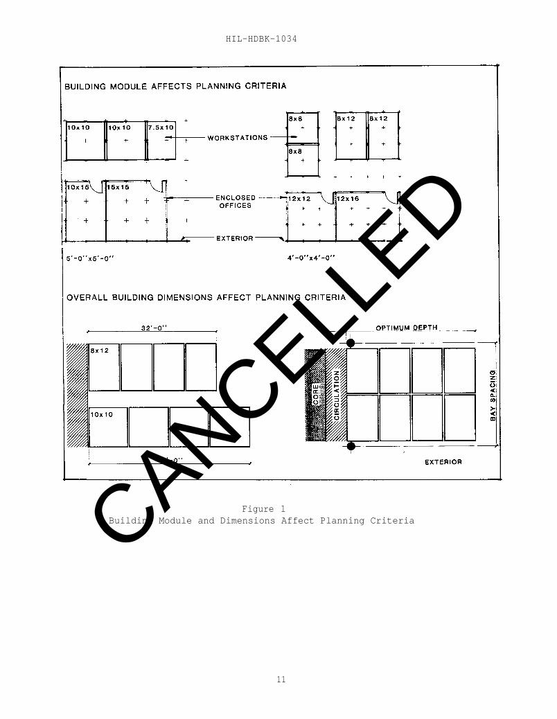
4.1.1 Building Elements. Building elements such as building module,column bay spacing, window-to-building core dimensions, and window spacingshould be evaluated as they relate to the sizes of offices, workstations, andequipment outlined in the user program (Figure 1).
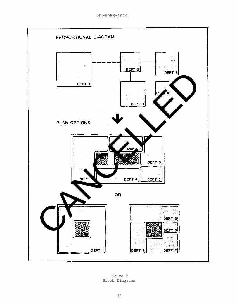
4.1.2 Floor Size and Building Configuration. Floor size and overallbuilding configurations should respond to the requirements of the user agency(Figure 2).
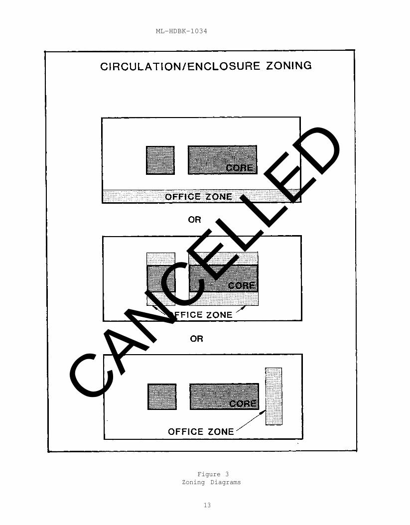
4.1.3 Zoning Diagrams. To ensure maximum flexibility, zoning diagramsshould be developed to allow the best distribution of open or enclosed spacesto respond to specific program data and management objectives (Figure 3).
4.1.4 Planning Criteria. Specific planning criteria should be developedregarding entry, circulation, office placement, and workstation placement.This criteria will become the basis of the initial space layout and for anyfuture changes. As such, they will maintain spatial clarity and ensureoptimum utilization of the facility.
4.2 Space Standards. Configurations and space standards for individualworkspaces should be developed for offices and workstations based uponfunctional requirements, including worksurface, seating, storage,meeting/supervisory activities, equipment, and privacy requirements.
4.2.1 Automated and Conventional Workstations. Automated workstations (anorganization of computer-interfaced equipment and task-supportive furnituredistinguished from the conventional workstation by the type and quantity ofequipment, the particular requirements of the tasks, and the criteria thatgovern the design of its furnishings) require 10 to 15 percent more area thanconventional workstations (an organization of separate components that supportstandard tasks and equipment such as typing and dictation).
4.2.1.1 VDT/Keyboard Configuration. VDT keyboard configurations requiredeeper worksurfaces than conventional typewriters.
4.2.1.2 Conventional Task Space. Space must be provided for conventionaltasks in addition to electronic equipment.
10
CANCELLED
HIL-HDBK-1034
Figure 1Building Module and Dimensions Affect Planning Criteria
11
CANCELLED
ML-HDBK-1034
Figure 2Block Diagrams
12
CANCELLED
ML-HDBK-1034
Figure 3Zoning Diagrams
13
CANCELLED
MIL-HDBK-1034
4.2.1.3 Additional Equipment. Additional peripheral equipment such as diskdrives, printers, and media storage may be required.
4.2.1.4 Special Equipment Requirements. Special requirements of specificequipment for access, ventilation, or acoustical separation may requireadditional space.
4.2.2 Shared Equipment. Shared equipment may require the development ofspecially configured work areas containing terminals, controllers, printers,viewers, etc., for general use of the work unit as a whole. Specificrequirements should be determined with the user agency.
4.3 Human Comfort. The increased usage of electronic equipment inadministration facilities has generated the need to ensure productive comfortlevels and proper equipment operations by considering the following factors indeveloping the HVAC systems design:
4.3.1 Temperature. The ambient temperature of office space is affected bythe cumulative heat generated by electronic equipment.
4.3.1.1 Equipment. The user agency should specify low heat generatingequipment.
4.3.1.2 Equipment Distribution. Distribute equipment uniformly throughoutthe space or provide special consideration for equipment-intensive areas.(Refer to Paragraph 4.9 and NAVFAC DM-12.01, Electronic FacilitiesEngineering.)
4.3.1.3 Heat Emission. Direct heat emission away from the operator andneighboring individuals.
4.3.2 Humidity/Static Control. HVAC systems design should maintainrelative humidity levels within the human comfort range and proper operatinglevels for electronic equipment. Design for a relative humidity range between40 percent and 60 percent in office areas. Specify antistatic carpet andfabrics. Maintain relative humidity above 30 percent.
4.3.3 Fresh Air. Provide fresh air flow requirements in accordance withNAVFAC DM-3 Series.
4.4 Power, Telephone, Data Distribution. With the advances inelectronic equipment, the introduction of computers into the officeenvironment, and the proliferation of telecommunications, the concealedrouting of cable to the end user point requires careful planning.
4.4.1 Power. Provide power outlets for offices and workstations asidentified in the design program. In addition, provide duplex convenienceoutlets approximately every 30 feet in corridors and other areas to allow useof janitorial equipment and other portable appliances. The followingalternatives are currently available for wiring distribution systems:
14
CANCELLED
MIL-HDBK-1034
4.4.1.1 Poke-Through System. Conduit or flexible wiring is brought througha hole or sleeve in the floor slab from the ceiling plenum below. This systemoffers low initial cost but provides less capacity and flexibility than othersystems.
4.4.1.2 Power Pole System. Wiring is brought through a pole from theceiling above. This system offers better flexibility but contributes to thevisual clutter of the space.
4.4.1.3 Conventional Walls and Columns. Wiring is brought from the ceilingthrough walls and columns to desired locations. This system does not alwaysallow the wires to be located where they are needed, especially in open planareas.
4.4.1.4 Wired Slabs. Wiring is brought through floor duct systems orthrough cellular raceways in the structural pan. These systems require anintegrated design approach that incorporates the design of workstations andtheir spacing with the location of predetermined outlet inserts.
4.4.1.5 Flat Conductor Cable. This system requires junction boxes at thebase of columns or core walls from which flat cable can be run whereverrequired. It must be used in conjunction with carpet tile.
4.4.1.6 Raised Floor Systems. These consist of a substructure that holds afloor panel system 3 to 18 inches above the subfloor. This system has thegreatest flexibility and capacity but has high initial cost.
4.4.2 Communications. Provide telephone service entrances, telephonecabinets, wire distribution system, and outlet boxes for telephones.
4.4.2.1 Telephone Outlet Boxes. Locate telephone outlet boxes as stipulatedin the design program and provide outlet boxes for public telephones asrequired.
4.4.2.2 Installation of Communications Systems. There are two methods ofinstalling communication systems: obtain telephone service (interior cable andend user instruments) via competitive procurement or obtain basic service fromthe local franchised common-carrier company and have cable and equipmentinstallation provided by the general contractor.
4.4.2.3 Interior Telephone Service. Interior telephone service (and theupgrade of existing cable distribution systems) should be coordinated with thelocal franchised common carrier, COMNAVTELCOM, or other Navy/DOD entityresponsible for telephone service.
4.4.3 Data. The location of electronic equipment in the officeenvironment may require connecting cables from the central processing unit(CPU) to specific terminals and/or printers or connecting several computerstogether in a Local Area Network (LAN).
15
CANCELLED
MIL-HDBK-1034
4.4.3.1 Distribution of Data Cable. Distribution of data cable may beaccomplished by any of the methods listed in Paragraph 4.4.1, with theexception that some equipment manufacturers may not endorse flat cable.
4.4.3.2 Installation of Local Area Network (LAN). There are two methods ofinstalling LAN: general contractor provides the wire distribution system only(the actual data cable is provided by the equipment installer) or the generalcontractor provides the complete LAN including distribution system and wiring.
4.5 Lighting. Provide energy efficient lighting in accordance with thedesign criteria in MIL-HDBK-1190 and NAVFAC DM-4.04.
4.5.1 Lighting Design Application. In administrative facilities, theemphasis should be placed on the design application. Consider the quality ofthe light as well as the quantity of light. Avoid excessive amounts ofillumination and glare.
4.5.1.1 Video Display Terminal (VDT) Area. Avoid high lighting contrasts inVDT use areas. The brightness ratios between the keyboard, the screen of thevideo display terminal, and surrounding surfaces should be 1:3:10,respectively.
4.5.1.2 Reflectance Values. Select materials with reflectance values asfollows: walls 40-80 percent, furniture/vertical surfaces 40-70 percent,worksurface 30 percent maximum, ceilings 80-90 percent, floors 20-40 percent.
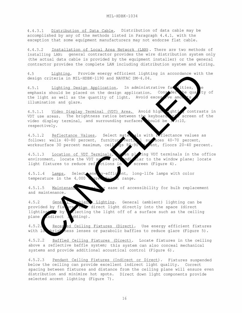
4.5.1.3 Location of VDT Terminals. When placing VDT terminals in the officeenvironment, locate the VDT screen perpendicular to the window plane; locatelight fixtures to reduce reflections in the screen (Figure 4).
4.5.1.4 Lamps. Select energy-efficient, long-life lamps with colortemperature in the 4,000 degree Kelvin range.
4.5.1.5 Maintenance. Consider ease of accessibility for bulb replacementand maintenance.
4.5.2 General (Ambient) Lighting. General (ambient) lighting can beprovided by fixtures that direct light directly into the space (directlighting) or by reflecting the light off of a surface such as the ceilingplane (indirect lighting).
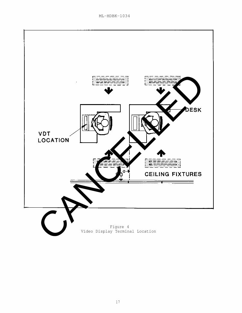
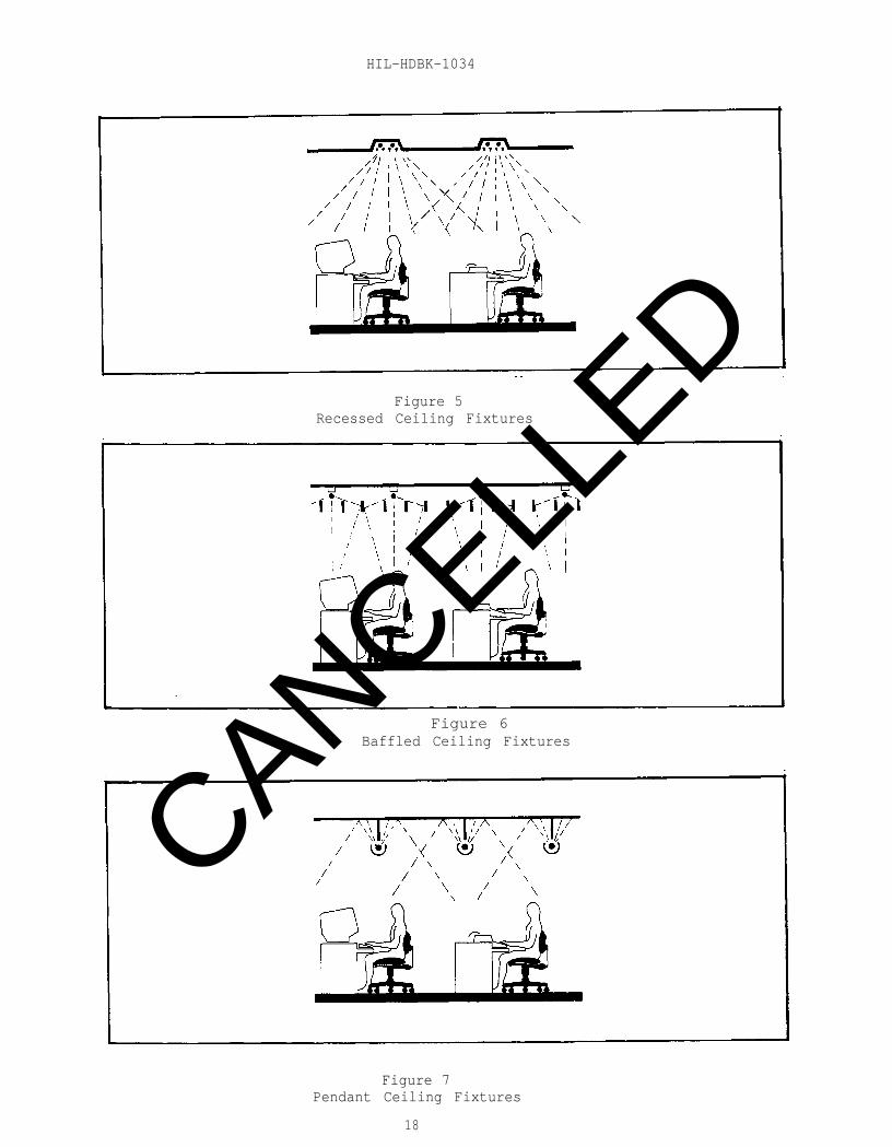
4.5.2.1 Recessed Ceiling Fixtures (Direct). Use energy efficient fixtureswith low brightness lenses or parabolic baffles to reduce glare (Figure 5).
4.5.2.2 Baffled Ceiling Fixtures (Direct). Locate fixtures in the ceilingabove a reflective baffle system; this system can also conceal mechanicalsystems and provide additional acoustical control (Figure 6).
4.5.2.3 Pendant Ceiling Fixtures (Indirect or Direct). Fixtures suspendedbelow the ceiling can provide excellent indirect light quality. Correctspacing between fixtures and distance from the ceiling plane will ensure evendistribution and minimize hot spots. Direct down light components provideselected accent lighting (Figure 7).
16
CANCELLED
ML-HDBK-1034
Figure 4Video Display Terminal Location
17
CANCELLED
HIL-HDBK-1034
Figure 5Recessed Ceiling Fixtures
Figure 6Baffled Ceiling Fixtures
Figure 7Pendant Ceiling Fixtures
18
CANCELLED
MIL-HDBK-1034
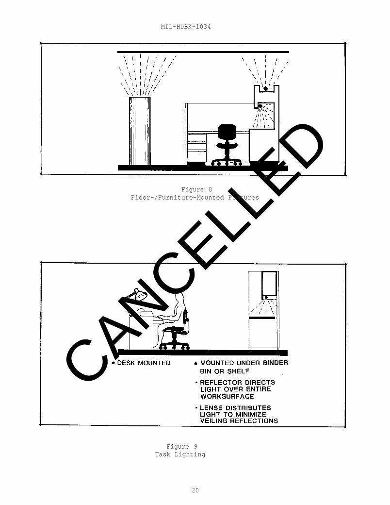
4.5.2.4 Floor- or Furniture-Mounted Fixtures. Floor-supported pedestals orfurniture-mounted fixtures (indirect) eliminate fixtures from the ceilingplane. Lighting design may be disrupted by relocation of furniture as changesoccur (Figure 8).
4.5.3 Task Lighting. Task lighting or lighting for use on a particulartask or work area supplements general ambient lighting. Placement and designof the fixture and lens should prevent glare and veiling reflections(Figure 9).
4.5.4 Accent Lighting. Provide selected accent lighting on verticalsurfaces to add shape and focus to the space.
4.5.5 General Maintained Light Levels. This information is furtherdefined to provide the following general maintained light levels:general ambient (overall light level in corridors and non-task-related areas)- 30 footcandles, (consider that screening panels will cast shadows and reduceeffective light levels), worksurfaces - 50 footcandles, and conference ormeeting areas - 30 footcandles:
4.6 Acoustics. Provide acoustical control in compliance with NAVFACDM-1.03, Architectural Acoustics. In the administration facility, considerprovisions to provide normal speech privacy (defined as the ability to hearconversations in adjacent workspace without understanding the overall meaningand content) in open plan and office areas; provide control for airborne andstructure-borne noise from equipment.
4.6.1 Noise Transfer. Plan offices and locate workstations with adequatedistance and entry orientation to minimize noise transfer.
4.6.2 Acoustically Absorbent Ceilings. In open areas, provideacoustically absorbent ceilings and select light fixtures that will minimizethe reflection of sound.
4.6.3 Sound Masking. Consider masking sound for open plan areas. (Referto DM-1.03.)
4.6.4 Acoustical Hoods and Isolation Pads. Provide acoustical hoods orisolation pads for printers and equipment generating impact noise.
4.7 Materials and Finishes. Specifications for interior materials andfinishes shall comply with NAVFAC DM-1 Series.
4.8 Furnishings. Furniture selections should be made to best supportthe activities being performed in the office or workstation. These activitieswill vary depending on the job responsibilities. Some typical functional jobcategories are management, professional, technical, data entry, clerical, etc.
19
CANCELLED
MIL-HDBK-1034
Figure 8Floor-/Furniture-Mounted Fixtures
Figure 9Task Lighting
20
CANCELLED
MIL-HDBK-1034
4.8.1 Task Requirements. Consider what the person actually does and whatis required to accomplish the task. Issues for consideration include:
a) Frequency of meetings held in the work area and the number ofparticipants at each meeting.
b) Confidentiality of information handled and conversations held.
c) Number, duration, and purpose of telephone conversations.
d) Requirement for concentration and freedom from distractions inorder to plan, read, write, etc.
e) Storage for files, binders, reports, books, reference manuals,equipment, etc.
f) Electronic equipment activities such as data entry, dataretrieval, word processing, programming.
4.8.2 Furniture Options. There are three basic. furniture options:
4.8.2.1 Conventional Furniture. Conventional furniture such as desks,chairs, tables, etc., accommodates tasks related to traditional workactivities and equipment (typing, reading, writing, dictation, etc.) but doesnot always meet the needs of automated equipment. Some manufacturers aredeveloping furniture items to support automated equipment in a conventionalenvironment.
4.8.2.2 Systems/Modular Furniture. Structural panels that support worksurfaces, lighting, and storage components provide privacy and acousticalcontrol in an open environment. These systems allow great flexibility forchanging organizations and provide components to satisfy almost any need.
4.8.2.3 Combination. Screening panels and conventional furniture may beused together to provide storage and privacy screening. This allows the reuseof existing equipment if required. It is sometimes difficult to achieve theoptimum layout and space utilization with this approach.
4.8.3 Seating. The selection of the task chair is critical to thepersonal comfort, physical health, and productivity of the occupant. Chairselection should be based on the following guidelines:
a) Adjustability. Allow the individual to adjust the seat height,back height, and tilt to meet his or her own needs.
b) Support. The chair should support the body in the correctposition, relieving pressure on the back and legs. The seat angle should besloped 3 to 5 degrees from front to back, and the front edge should bedesigned to relieve pressure on the thighs. The back should be shaped tosupport the correct spinal curvature.
c) Seat Height. Proper seat height allows the feet to rest on thefloor while the thighs remain horizontal.
21
CANCELLED
MIL-HDBK-1034
d) Seat Width and Depth. The seat width and depth should evenlydistribute body weight.
e) Armrests. Armrest designs should support the arm at the correctheight but not impair movement. The armrest should be designed to allow thechair to be pulled close enough to the work surface to perform whatever taskis required.
f) Task Chairs. Task chair bases should have casters to allowmovement within the work area. Five-star bases do not tip over as easily andare more maneuverable than bases with only four prongs.
4.8.4 Evaluation of Workstation Design. Criteria for evaluating aworkstation design include:
a) Adjustability. The user should be able to make minor height orangle adjustments to satisfy his individual needs.
b) Simplicity. With fewer components involved, inventory controland facility management are much easier.
c) Flexibility. The equipment should be easy to disassemble orreassemble with a minimum amount of effort and with simple tools. Ifpossible, the workstation should be able to be moved as a whole unit.
d) Convenience. Frequently used equipment and reference materialshould be within easy reach of the user.
e) Visual Sight Line. The user should be able to see other workerswhen necessary.
f) Layout should allow free leg movement under the work surface.
g) Entrances. Entrances should be wide enough to allow ease ofpassage; 36 inches is comfortable, 32 inches minimum.
h) Storage. Enough of the correct type of storage should beprovided (legal, letter, forms, card, tape, binder, etc.).
i) Stability. The surfaces should support heavy equipment loadsand resist tipping. Panels should not sway or move when lateral pressure isapplied.
j) Maintenance. The equipment should be easy to maintain.Surfaces should be easy to clean. Upholstery should be easy to replace. Allmaterials should resist damage.
k) Construction. There should be no sharp comers or protrudingedges.
1) Privacy. The workstation should provide appropriate visual andacoustical privacy.
22
CANCELLED
MIL-HDBK-1034
m) Cable Raceways. Power, data, and communication cables should beaccommodated through convenient raceways and access points.
n) Lighting. Lighting should be adjustable and positioned to avoidglare and ceiling reflections.
4.8.5 Evaluation of Products and Vendors. Criteria for evaluating andcomparing products and vendors include:
a) Comprehensive Product Line. The anticipated components shouldbe available from one source.
b) Module. Heights and widths should correspond with the ceilingheights and building dimensions.
c) Responsiveness. The manufacturer and/or dealer should beavailable to provide training and to assist in solving problems.
d) Cost. Material and finish options should allow the user totailor selections to fit budget constraints.
e) Aesthetics. The furnishings should support and extend thedesign concept of the facility.
f) Manufacturing Capability and Delivery Time. The vendor shouldbe able to provide the amount of equipment required within a reasonable periodof time. While production schedules vary, most manufacturers will deliverwithin 12 weeks of receipt of an order of a standard product. Somemanufacturers offer rapid shipment (sometimes as little as 2 weeks) on limitedproduct selections.
4.9 Areas Housing Electronic Equipment
4.9.1 General Architectural Requirements. While most automated equipmentno longer requires special environmental conditions and is often foundcontiguous with the office environment in an administration facility, certainapplications require the concentration of equipment in a relatively smallarea. Areas housing electronic equipment require special treatment to assureoperating efficiency, comfort of personnel, and fire safety. (Refer toMIL-HDBK-1008.) Special provisions are required when an area is designated asa Sensitive Compartmented Information Facility (SCIF). (Refer to DefenseIntelligence Agency Memorandum (DIAM) 50-3, Control of Compromising Emanations.
4.9.1.1 Applicability. Criteria for communications facilities are containedin DM-12.01.
4.9.1.2 Equipment. The degree of special treatment varies according to thenature and extent of equipment. Generally, the following items requireadditional consideration: electronic data processing machines (EDPM),permanently installed radio receiver and transmitting equipment, and teletypeequipment.
23
CANCELLED
MIL-HDBK-1034
4.9.1.3 Location. Areas housing electronic equipment must be isolated fromareas accessible to the public. In one-story buildings, consider locatingthese areas away from the main lobby. In two-story buildings, considerlocating these areas on the second floor. Electronic equipment areas shouldnot be located adjacent to or below toilet areas, kitchens, or other areascontaining plumbing, drain lines, or water piping.
4.9.2 Construction. The following criteria shall be used in constructionplanning. Material and building system selection shall be based on:
4.9.2.1 Exterior Walls. One of the following: concrete masonry units orbrick, reinforced concrete (where required), or lightweight steel frame withmetal curtain walls of galvanized metal, aluminum, or similar material.
4.9.2.2 Floors. In areas housing extensive equipment, provide floor systemsfor electrical flexibility. (Refer to Paragraph 4.4.)
4.9.2.3 Windows. In areas housing electronic equipment, windows can beprovided if such provision does not reduce operating efficiency of theequipment or create a security hazard. Windows, if provided, should be placedhigh, except where they occur in offices or workstations. Double or tripleglass windows with thermal barriers may be required, depending on outsidedesign temperature. Window construction and finish should be of a type thatrequires minimum maintenance. For glazing requirements, refer to ANSISpecification Z97.1, Safety Glazing Materials Used in Buildings, andNFGS-08800, Glazing.
4.9.3 Heating and Ventilating Requirements. These standards and criteriaapply primarily to planning and design of ventilating and air conditioningsystems. They fulfill temperature and humidity control requirements foroperation of electronic data computer systems and related areas, such as tapestorage rooms, machine repair rooms, administration areas, and planning areassupporting an electronic data processing facility. Use NAVFAC DM-3 Series forgeneral design criteria for heating, ventilating, and air conditioningequipment. For special heating, ventilating, and air conditioningrequirements in communication areas, refer to NAVFAC DM-12.01. Climate andweather conditions can be obtained from P-89, Engineering Weather Data.
4.9.4 Fire Protection. See MIL-HDBK-1008 for details of fire protectionrequirements for air conditioning equipment and for electrical distributioninstallation.
24
CANCELLED
MIL-HDBK-1034
Section 5: MODERNIZATION OF EXISTING ADMINISTRATIVE FACILITIES
5.1 Modernization. It is intended to bring the livability of existingsemipermanent and permanent administration buildings to a level comparablewith current standards in new construction. Buildings selected formodernization should be structurally sound, architecturally acceptable, andeconomically feasible, based on an actual feasibility study comparingmodernization and new construction costs. NAVFAC criteria for newconstruction should be applied to modernization projects to the maximum extentfeasible in accordance with good architectural and engineering judgement.
5.2 Architectural Requirements. The following items provide guidance onbasic modernization techniques:
5.2.1 Lobby. The main entrance lobby should be made attractive. Newentrance doors and the provision of canopies should be considered wherecovered entryways are not provided. All nonlobby functions such as vendingmachines, filing, shelving, etc., should be removed from the lobby and placedin an area specifically assigned for each function. A suitable display areaindigenous to the local command is appropriate.
5.2.2 Acoustics. Provide acoustical treatment with high noise reductioncoefficient (NRC) in all areas where there is a high noise level, particularlyin data processing and message communication areas. Provide acousticaltreatment with high sound transmission coefficient (STC) in areas requiringprivacy, such as conference rooms. (Refer to the NAVFAC DM-1 Series.)
5.2.3 Floors. Where the present floor surface is concrete, installresilient floor tile or carpeting with appropriate base. If the present flooris of wood, tile, or linoleum, provide new tile or carpeting only if theexisting floor is excessively worn and unattractive. The use of carpet shallbe in accordance with NAVFAC DM-14.02, Carpet Selection Guide.
5.2.4 Interior Finishes. Where interior finishes need replacement, theyshall conform to the interior finish requirements in MIL-HDBK-1190 andMIL-HDBK-1008.
5.2.5 Colors. Colors shall conform to NAVFAC P-309 and DM-1.01.
5.2.6 Signage. To assist the users and visitors of the building, asignage system shall be provided. Refer to NAVFAC NFGS-10440.
5.2.7 Fire Protection. Fire protection shall conform to MIL-HDBK-1008.
5.2.8 Handicapped Facilities. Handicapped facilities shall conform toMIL-HDBK-1190 and the NAVFAC DM-1 Series.
25
CANCELLED
MIL-HDBK-1034
5.3 Structural Requirements. Modernization of existing structures shallbe investigated and upgraded seismically in accordance with NAVFAC P-355.Where modifications are made to improve functional operations, the structuralsystem can be modified, provided that the new loading distribution caused bysuch modifications does not overload existing members. When it is determinedthat the structural system will not meet the design loads, those members thatare considered inadequate should be strengthened, modified, and/or replaced.The structural systems should be inspected; where deficiencies are noted,maintenance and repair work should be performed.
5.4 Electrical Requirements. Lighting, power, and telephone systemsshould be in accordance with the requirements of the NAVFAC DM-4 Series,NFPA-70, and Paragraphs 4.4 and 4.5.
5.4.1 Reuse. Wiring and transformer capacities should be checked foradequacy with respect to current and future load requirements and upgraded asnecessary. Equipment judged to be in safe and operable condition should bereused.
5.4.2 Special Systems. Special systems requirements should be inaccordance with the NAVFAC DM-32 Series, Storage, and as outlined inParagraph 4.9.
5.4.3 Lighting. Where lighting intensities are deficient, existinglighting fixtures should be supplemented or replaced with more efficientlighting fixtures for the required intensity.
5.5 Mechanical Requirements. The following mechanical requirementsshould be observed in the modernization of existing buildings: The number ofplumbing fixtures specified in MIL-HDBK-1190 should be provided. New toiletaccessories should be provided where deficiencies exist. Plumbing shouldconform to the minimum requirements set forth in the NAVFAC DM-3 Series.
5.6 Energy Conservation. In an existing building, the site (geographiclocation), orientation, controls, equipment sizes, and selections areessentially fixed. However, the values of other basic parameters such asventilation, infiltration, building envelope, "U" factor (walls, floor, glass,roof), and shading can be improved and should be evaluated as accurately aspossible for energy and cost-effective improvement. The existing HVACequipment should be evaluated and potentially modified to comply with theenergy conservation requirements in DM-3.03. (Refer to the NAVFAC DM-3 Seriesand MIL-HDBK-1190.)
5.7 Toxic Materials. Existing building products containing asbestos orother toxic materials should be removed in accordance with NFGS-02075, Removaland Disposal of Asbestos Materials; OPNAVINST 5100.23B, Navy OccupationalSafety and Health Program; OSHA Standards 1910 Series; and other currentFederal and industry standards.
5.8 Fire Protection and Life Safety. Fire protection and life safetyrequirements shall be in accordance with MIL-HDBK-1008 and NFPA 101.
26
CANCELLED
MIL-HDBK-1034
Section 6: FLAGSTAFFS
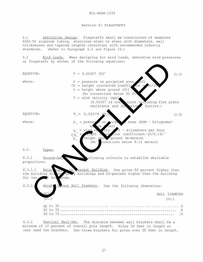
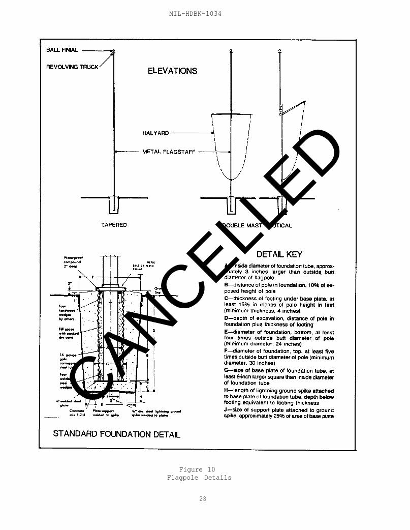
6.1 Definitive Design. Flagstaffs shall be constructed of seamless6063-T6 aluminum tubing, stainless steel or steel with diameters, wallthicknesses and tapered lengths consistant with recommended industrystandards. (Refer to Paragraph 6.3 and Figure 10.)
6.2 Wind Loads. When designing for wind loads, determine wind pressureson flagstaffs by either of the following equations:
EQUATION: P = 0.00307 ChV2
(1-1)
where: P = pressure on projected area (psf)Ch = height corrected coefficient = (h/30)2/7
h = height above ground (ft)(No corrections below 30 ft.)
V = wind velocity (mph)(0.00307 is coefficient including flat plateresistance and dimensional factors.)
EQUATION: P m = 0.00579 ChmVm
2
(1-2)
where: P m= pressure on projected area (KSM - kilograms/
square meter)
V m= wind velocity (KPH - kilometers per hour
C hm= height correction coefficient-(h/9.14)2/7
h m= height above ground (m-meters)
(No corrections below 9.14 meters)
6.3. Types.
6.3.1 Ground-Set. Use the following criteria to establish desirableproportions:
6.3.1.1 Relationship to Nearest Building. Use poles 50 percent higher thanthe building for one-story buildings and 25-percent higher than the buildingfor two-story buildings.
6.3.1.2 Height Versus Ball Diameter. Use the following dimensions:
HEIGHT BALL DIAMETER(ft.) (in.)
up to 30 . . . . . . . . . . . . . . . . . . . . . . . . . . . . . . . . . . . . . . . . . . . . . . . . . . . . 640 to 50 ............................................................ 860 to 70 ........................................................... 10
6.3.2 Vertical Wall-Set. The distance between wall brackets shall be aminimum of 10 percent of overall pole length. Poles 30 feet in length orless need two brackets. Use three brackets for poles over 30 feet in length.
27
CANCELLED
MIL-HDBK-1034
Figure 10Flagpole Details
28
CANCELLED
MIL-HDBK-1034
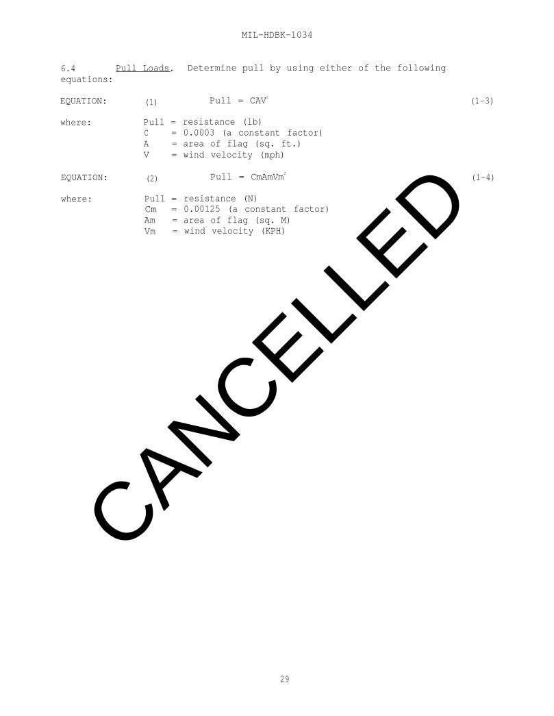
6.4 Pull Loads. Determine pull by using either of the followingequations:
EQUATION: (1) Pull = CAV2(1-3)
where: Pull = resistance (lb)C = 0.0003 (a constant factor)A = area of flag (sq. ft.)V = wind velocity (mph)
EQUATION: (2) Pull = CmAmVm2(1-4)
where: Pull = resistance (N)Cm = 0.00125 (a constant factor)Am = area of flag (sq. M)Vm = wind velocity (KPH)
29
CANCELLED

MIL-HDBK-1034
30
CANCELLED
MIL-HDBK-1034
BIBLIOGRAPHY
Accessibility Modifications. Mace, Ronald L., North Carolina Department ofInsurance, Raleigh, NC 27611.
American Society of Heating. Refrigeration. and Air Conditioning Engineers,Inc. (ASHRAE) 1791 Tullie Circle, NE., Atlanta, GA 30329.
An Illustrated Handbook of the Handicapped Section of the North Carolina StateBuilding Code, Mace, Ronald L., North Carolina.
Architectural Graphic Standards, Ramsey-Sleeper, John Wiley & Sons, New York,NY 10016.
Designing the Automated Office, Pulgram, William, and Stonis, Richard E.,Whitney Library of Design, 1515 Broadway, New York, NY 10036.
Electric Power for ADP Installations, FIPS PUB-94, National TechnicalInformation Service, U.S. Department of Commerce, Springfield, VA 22161.
Guidelines for Facility Design and Red/Black Installation (U), NavalElectronic Security Engineering Center, 3801 Nebraska Avenue, NW.Washington, DC 20390-5270.
Illuminating Engineering Society (IES). Lighting Handbook, 345 East 47thStreet, New York, NY 10017.
NBX Atmospheric Air Dust Stain Test, National Bureau of Standards. Copies canbe obtained from the National Technical Information Service, U.S. Departmentof Commerce, Springfield, VA 22161.
Security Managers Handbook, Department of the Navy, Office of the Chief ofNaval Operations, Office of Naval Intelligence, Washington, DC 20350.
Time Saver Standards, McGraw-Hill Book Company, New York, NY 10020.
31
CANCELLED

MIL-HDBK-1034
32
CANCELLED
MIL-HDBK-1034
REFERENCES
American National Standards Institute, Inc. (ANSI), 1430 Broadway, New York,New York, 10008.
Z97.1 Safety Glazing Materials Used in Buildings
A117.1 Specifications For Making Buildings and FacilitiesAccessible by Physically Handicapped People
Department of the Navy, Copies of Design Manuals (DMs), Publications (Ps),Military Handbooks (MIL-HDBKs), and Chief of Naval Operations Instructions(OPNAVINSTs) can be obtained from the U.S. Naval Publications and FormsCenter, 5801 Tabor Avenue, Philadelphia, PA 19120. Copies of DefinitiveDesigns (DDs) can be obtained from any of the following Engineering FieldDivision Offices:
CommanderAtlantic Division Code 04A4Naval Facilities Engineering CommandNorfolk, VA 23511-6287
Telephone: (804) 444-9970
CommanderChesapeake Division Code 04Naval Facilities Engineering CommandWashington Navy Yard, Building 212Washington, DC 20374-2121
Telephone: (202) 433-3314
Commanding OfficerNorthern Division Code 04ABNaval Facilities Engineering CommandPhiladelphia, PA 19112
Telephone: (215) 897-6153
CommanderPacific Division Code 406CNaval Facilities Engineering CommandPearl Harbor, HI 96869
Telephone: (808) 471-8436
Commanding OfficerSouthern Division Code 04A3Naval Facilities Engineering CommandP.O. Box 10068Charleston, SC 29411-0068
Telephone: (803) 743-0458
33
CANCELLED
MIL-HDBK-1034
REFERENCES (Continued)
CommanderWestern Division Code 406CNaval Facilities Engineering CommandP.O. Box 727San Bruno, CA 94066-0720
Telephone: (415) 877-7422
Naval Facilities Engineering Command (NAVFACENGCOM)
DM-1 Series
DM-1.01
DM-1.03
DM-2 Series
DM-3 Series
DM-3.01
DM-3.03
DM-4 Series
DM-4.04
DM-4.09
DM-5 Series
MIL-HDBK-419
MIL-HDBK-1008
MIL-HDBK-1013/1
DM-12.01
DM-14.02
DM-32 Series
MIL-HDBK-1190
Architecture
Basic Architectural Requirements and DesignConsiderations
Architectural Acoustics
Structural Engineering
Mechanical Engineering
Plumbing Systems
Heating, Ventilating, Air Conditioning, andDehumidifying Systems
Electrical Engineering
Electrical Utilization Systems
Energy Monitoring and Control Systems
Civil Engineering
Grounding, Bonding, and Shielding for ElectronicEquipment and Facilities
Fire Protection for Facilities Engineering, Designand Construction
Physical Security
Electronic Facilities Engineering
Carpet Selection Guide
Storage
Facility Planning and Design Guide
34
CANCELLED
MIL-HDBK-1034
REFERENCES (Continued)
P-80 Facility Planning Criteria for Navy and MarineCorps Shore Installations
P-89 Engineering Weather Data
P-272 Definitive Designs for Naval Shore Activities
P-309 Color for Naval Shore Facilities
P-355 Seismic Design for Buildings
NFGS-02075 Removal and Disposal of Asbestos Materials
NFGS-08800 Glazing
NFGS-10440 Signs
DD-1404370 Parking Area Criteria for Vehicles
Office of the Chief of Naval Operations
OPNAVINST 5100.23B Navy Occupational Safety and Health Program
OPNAVINST 5510.16 Information and Personnel Security ProgramRegulations
OPNAVINST 5530.14A Physical Security and Loss Prevention Manual,16 September 1985
National Fire Protection Association (NFPA), Batterymarch Park, Quincy,MA 02269.
NFPA 70 National Electric Code
NFPA 101 Life Safety Code
Naval Intelligence Command (NIC)31, Physical Security Standards for SensitiveCompartmented Information Facilities - Defense Intelligence Agency Memorandum(DIAM) 50-3, Control of Compromising Emanations. Copy can be obtained fromNaval Intelligence Command, 4600 Silver Hill Road, Washington, DC 20389.
Occupational Safety and Health Act of 1970 (OSHA). Public Law 91-596. Copiescan be obtained from the Superintendent of Documents, U.S. Government PrintingOffice, Washington, DC 20402.
Uniform Federal Accessibility Standards. Federal Register, Vol. 49, No. 153,August 7, 1984. Copies can be obtained from the Superintendent of Documents,U.S. Government Printing Office, Washington, DC 20402.
35
CANCELLED

MIL-HDBK-1034
CUSTODIANNAVY-YD
PREPARING ACTIVITYNAVY-YD
PROJECT NO.FACR-0191
36
CANCELLED
STANDARDIZATION DOCUMENT IMPROVEMENT PROPOSAL(See Instructions - Reverse Side)
1. DOCUMENT NUMBER 2. DOCUMENT TlTLE
MIL-HDBK-1034 ADMINISTRATIVE FACILITES3a. NAME OF SUBMITTING ORGANIZATION 4. TYPE OF ORGANIZATION (Mark one)
o VENDOR
b. ADDRESS (Street, City State, ZIP Code)
5. PROBLEM AREASa. Paragraph Number and Wording:
o USER
o MANUFACTURER
o OTHER (Specify):
b. Recommended Wording:
c. Reason/Rationale for Recommendation:
6. REMARKS
7a. NAME OF SUBMITTER (Last, First, MI) - Optional b. WORK TELEPHONE NUMBER (Include AreaCode) - Optional
c. MAILING ADDRESS (Street, City, State, ZIP Code) - Optional 8. DATE OF SUBMISSION (YYMMDD)
PREVIOUS EDITION IS OBSOLETE.
CANCELLED

INSTRUCTIONS: In a continuing effort to make our standardization documents better, the DoD provides this form for use insubmitting comments and suggestions for improvements. All users of military standardization documents are invited to provide
suggestions. This form may be detached, folded along the liner indicated, taped along the loose edge (DO NOT STAPLE), andtiled. In block 5, be as specific as possible about particular problem areas such as wording which required interpretation, wastoo rigid, restrictive, loose, ambiguous, or was incompatible, and give proposed wording changes which would alleviate theproblems. Enter in block 6 any remarks not related to a specific paragraph of the document. If block 7 is filled out, anacknowledgement will be mailed to you within 30 days to let you know that your comments were received and are beingconsidered.
NOTE: This form may not be used to request copies of documents, nor to request waivers, deviations, or clarification ofSpecification requirements on current contracts. Comments submitted on this form do not constitute or imply authorizationto waive any portion of the referenced document(r) or to amend contractual requirements.
(Fold along this line)
(Fold along this line)
DEPARTMENT OF THE NAVY
OFFICIAL BUSINESSPENALTY FOR PRIVATE USE $300 BUSINESS REPLY MAIL
FIRST CLASS PERMIT NO. 12503 WASHINGTON D. C.
POSTAGE WILL BE PAID BY THE DEPARTMENT OF THE NAVY
NO POSTAGENECESSARYIF MAILED
IN THEUNITED STATES
COMMANDER, WESTERN DIVISIONNAVAL FACILITIES ENGINEERING COMMANDCODE 406P.O. BOX 727SAN BRUNO, CA 94066
CANCELLED
MIL-HDBK-1034
2.4.10.7 Color Application. A conservative approach to color is best forsmall enclosed spaces, such as interior offices. Too much intense hue willpsychologically tire an occupant quickly.
2.4.10.8 Value and Intensity of Hue. Value and intensity of hue play crucialroles in the specification of color. The lighter, more pastel, and neutralvalues provide better design solutions for background areas of floors, walls,and ceilings. Neutral colors are less inhibitive when used in materials andfurnishings. They reflect light better, provide an open expansion to thespace, and support the use of deep value accents or patterned materials.
2.4.10.9 Strong Colors. Strong colors, if used too extensively on one sideof a room, create a spatial imbalance.
2.4.10.10 Pale Pastel Colors. Pale, pastel colors make walls look light,contributing to a feeling of openness. In a small room, walls can be made toseem to recede by painting them in light values of cool colors such as greenor blue. Saturated colors absorb a great deal of light, contributing to asense of heaviness.
2.4.10.11 Principles of Spatial Manipulation. The following statements areprinciples of spatial manipulation through the use of color:
a) Dark ceilings will visually lower the apparent height of a room.
b) Dark or strong-valued ceilings and floors will jointly unify aspace.
c) Light ceilings will visually increase the apparent height of aroom, while light walls will expand a space.
d) Strong color on an end wall will visually shorten the length ofa room. Conversely, cool colors will recede a plane.
e) Strong color on a wall will call attention to itself.
f) A brightly colored wall will appear larger than it actually is,because the retina is more actively stimulated than with a greyed hue.
g) A light wall will emphasize dark objects placed in front of it.
h) A dark wall will make light colors or tints appear brighter.
i) Color can direct movement through a space: in furnishings, ingraphics, or through the relationship of colors between surrounding andadjoining spaces.
j) Light objects will appear larger in dimension against a whitebackground.
k) In order to balance light and dark areas in relation to oneanother, light areas should be smaller in size than dark areas.
CANCELLED

MIL-HDBK-1034
l) Strong color, coupled with texture, can camouflage undesirablearchitectural elements.
m) Colors affect and modify one another. Therefore, it isnecessary to give careful consideration to the effects of one color on another.
o) Colors of deep value in too great a quantity will make the wallsof a room appear heavy; pale colors will impart a feeling of lightness andexpansion.
2.4.11 Signage. A sign system shall be provided for direction,identification, and regulation of spaces. Both interior and exterior signsshall be included to orient, direct, and control pedestrian and vehiculartraffic (refer to NAVFAC NFGS-10440, Signs).
2.4.12 Vending/Cafeteria Area. The Randolph Sheppard Act requires that aninvitation be given to blind vendors to establish a vending or cafeteria areawithin the building.
2.4.13 Access for the Physically Handicapped. The building shall bedesigned to ensure accessibility for the physically handicapped in accordancewith the Uniform Federal Accessibility Standards, Federal Register, Vol. 49,No. 153, August 7, 1984, and MIL-HDBK-1190.
2.4.14 Security. Identify all areas requiring physical security with theuser agency of the specific administration facility; security provisions shallbe in compliance with MIL-HDBK-1013/1, Physical Security. Some areas inadministration buildings have special requirements for excluding unauthorizedpersonnel and for protecting Government property and classified information.Coordinate with the project sponsor to obtain applicable securityrequirements. General requirements for physical security are included inOPNAVINST 5530.14A, Physical Security and Loss Prevention Manual, Office ofthe Chief of Naval Operations, 16 September 1985. OPNAVINST 5510.16,Information and Personnel Security Program Regulations, Office of the Chief ofNaval Operations, shall apply for classified information. All areas’ requiringsecurity measures should be grouped together to facilitate control. Theserestricted areas are classified as follows:
2.4.14.1 Exclusion Area. An exclusion area is an area containing classifiedinformation of such nature that access to the area constitutes, for allpractical purposes, access to classified information.
2.4.14.2 Limited Area. A limited area is defined as an area containingclassified information and in which uncontrolled movement would permit accessto the classified information, but within which access may be prevented byescort and other internal restrictions and controls.
CHANGE 1, MARCH 1988
CANCELLED

STANDARDIZATION DOCUMENT IMPROVEMENT PROPOSAL(See Instructions - Reverse Side)
1. DOCUMENT NUMBER 2. DOCUMENT TlTLE
MIL-HDBK-1034 ADMINISTRATIVE FACILITES3a. NAME OF SUBMITTING ORGANIZATION 4. TYPE OF ORGANIZATION (Mark one)
o VENDOR
b. ADDRESS (Street, City State, ZIP Code)
5. PROBLEM AREASa. Paragraph Number and Wording:
o USER
o MANUFACTURER
o OTHER (Specify):
b. Recommended Wording:
c. Reason/Rationale for Recommendation:
6. REMARKS
7a. NAME OF SUBMITTER (Last, First, MI) - Optional b. WORK TELEPHONE NUMBER (Include AreaCode) - Optional
c. MAILING ADDRESS (Street, City, State, ZIP Code) - Optional 8. DATE OF SUBMISSION (YYMMDD)
PREVIOUS EDITION IS OBSOLETE.
CANCELLED