Embed Size (px)
Citation preview
**************************************************************************USACE / NAVFAC / AFCEC / NASA UFGS- 33 52 40 ( November 2018) Change 1 - 08/ 19 - - - - - - - - - - - - - - - - - - - - - - - - - - - - -Pr epar i ng Act i v i t y: NAVFAC Super sedi ng UFGS- 33 52 43 ( May 2011)
UNI FI ED FACI LI TI ES GUI DE SPECI FI CATI ONS
Ref er ences ar e i n agr eement wi t h UMRL dat ed Oct ober 2019**************************************************************************
SECTION TABLE OF CONTENTS
DIVISION 33 - UTILITIES
SECTION 33 52 40
FUEL SYSTEMS PIPING (NON-HYDRANT)
11/18
PART 1 GENERAL
1.1 SUMMARY 1.2 REFERENCES 1.3 ADMINISTRATIVE REQUIREMENTS 1.4 SUBMITTALS 1.5 QUALITY ASSURANCE 1.5.1 Contractor Qualifications 1.5.2 System Supplier 1.5.3 Work Plan 1.5.4 Pigging Plan 1.5.5 Hydrotesting Plan 1.5.6 Water for [Hydrotesting][Pigging] 1.5.7 Design Data 1.5.7.1 Pipeline Inventory 1.5.8 Material and System Components Qualifications 1.5.9 Nameplates 1.5.10 Delivery, Storage, and Handling
PART 2 PRODUCTS
2.1 ELECTRICAL WORK 2.1.1 General 2.1.2 Grounding and Bonding 2.2 MATERIALS 2.2.1 Types of Fuel 2.2.2 Carbon Steel Piping 2.2.3 Stainless Steel Piping 2.2.4 Steel Reinforced Flexible Pipe 2.2.5 External Protective Coatings for Aboveground Piping 2.2.6 External Protective Coatings for Buried Steel Piping 2.2.6.1 Carbon Steel Piping 2.2.6.2 Stainless Steel Piping 2.2.6.3 Rock Shield, Direct Buried Piping 2.2.7 Fittings
SECTION 33 52 40 Page 1
2.2.7.1 General 2.2.7.2 Carbon Steel Fittings 2.2.7.3 Stainless Steel Fittings 2.2.7.4 Steel Reinforced Flexible Pipe Fittings 2.2.8 Insulating Flange Kits (Electrically Isolating) 2.2.9 Bolts, Nuts and Washers 2.2.10 Gaskets 2.2.11 Flange Protectors 2.3 MANUAL VALVES 2.3.1 Ball Valves 2.3.1.1 Materials 2.3.1.2 V-Port Ball Valve 2.3.1.3 Full Port Ball (DBBV) Valves for Piggable Lines 2.3.1.4 Electric Valve Actuator 2.3.2 Plug (Double Block and Bleed) Valves 2.3.2.1 General 2.3.2.2 Valve Operation 2.3.2.3 Relief Valves 2.3.2.4 Bleed Valves 2.3.2.5 Electric Valve Actuator 2.3.3 Swing Check Valves 2.3.4 Silent Check Valves 2.3.5 Butterfly Valve with Fusible Link Operator 2.3.6 Globe Valve 2.4 THERMAL RELIEF VALVE 2.4.1 Valve Material 2.4.2 Thermal Relief Valve (ASME Type) 2.4.3 Thermal Relief Valve (Balanced Type) 2.5 PIPING ACCESSORIES 2.5.1 Flexible Ball Joints 2.5.2 Bellows Expansion Joints for Axial Movement 2.5.3 Mechanically Adjustable Segmented Elastomeric Seal 2.5.4 Pipe Sleeves 2.5.5 Strainers 2.5.5.1 Basket Type 2.5.5.2 Cone Type 2.5.6 Thermometer 2.5.7 Pressure Gauge 2.5.8 Pipe Supports 2.5.8.1 General 2.5.8.2 Adjustable Pipe Supports 2.5.8.3 Low Friction Supports 2.5.8.4 U-bolt Half Round Supports 2.5.8.5 Concrete and Grout 2.5.9 Sample Connections 2.5.10 Sight Flow Indicators 2.6 PIGGING SYSTEM COMPONENTS 2.6.1 Maintenance Pig Launchers and Receivers 2.6.2 Smart Pig Launchers and Receivers 2.6.3 Launcher and Receiver Closure Door 2.6.4 Signaler 2.7 FLEXIBLE HOSE CONNECTORS 2.8 AUTOMATIC AIR VENT 2.9 SURGE SUPPRESSOR TANK AND VALVE 2.10 MISCELLANEOUS ACCESSORIES 2.10.1 Concrete Anchor Bolts 2.10.2 Coatings for Bolts, Studs, Nuts, and Washers 2.10.3 Polytetrafluoroethylene (PTFE) Tape 2.10.4 Pipe Sleeves
SECTION 33 52 40 Page 2
2.10.5 Escutcheon 2.10.6 Pipe Casings 2.10.7 Buried Utility Tape 2.10.8 Pipeline Markers 2.11 FINISHES 2.11.1 Factory Coating 2.11.1.1 Valves 2.11.1.2 Equipment and Components 2.11.2 Field Painting
PART 3 EXECUTION
3.1 GENERAL 3.2 VERIFICATION OF DIMENSIONS 3.3 CLEANING OF PIPING 3.4 TRENCHING AND BACKFILLING 3.5 PIPING LAYOUT REQUIREMENTS 3.5.1 Pipe Fabrication 3.5.2 Interferences and Measurements 3.5.3 Space and Access 3.5.4 Location 3.5.5 Pipe Supports 3.5.6 Structural Support 3.5.7 Grade 3.5.8 Size Changes 3.5.9 Direction Changes 3.5.10 Threaded End Connections 3.5.11 Existing Pipe Systems 3.5.12 Bolted Connections 3.5.13 Flanges and Unions 3.5.14 Flange Protector 3.5.15 Manual Valves 3.5.16 Air Vents 3.5.17 Drains 3.5.18 Bellows Expansion Joints 3.5.19 Thermometers 3.5.20 Pipe Sleeves 3.5.21 Escutcheons 3.6 SEISMIC REQUIREMENTS 3.7 STRUCTURAL ATTACHMENTS 3.8 WELDING 3.8.1 General 3.9 INSTALLATION 3.9.1 Precautions 3.9.2 Protective Coatings for Buried Piping Including Stainless
Steel Piping 3.9.2.1 Application of Coating System 3.9.2.2 Inspection and Testing 3.9.2.3 Damage Repair 3.10 INTERIOR EPOXY COATING 3.11 INSTALLATION OF UNDERGROUND PIPE 3.11.1 Pipe Assembly 3.11.2 Warning Tapes in Earth Trenches 3.11.3 Clearances 3.11.4 Protective Coating 3.11.5 Pipe Casing 3.11.6 Pipeline Markers 3.11.7 Steel Reinforced Flexible Pipe 3.12 SYSTEM COMMISSIONING
SECTION 33 52 40 Page 3
3.13 TESTING 3.13.1 Before Backfilling 3.13.1.1 Exterior Coating Holiday Test 3.13.2 Pneumatic Test 3.13.2.1 Pneumatic Test Procedure 3.13.3 Hydrostatic Test 3.13.4 Soak Testing 3.13.5 Performance Testing 3.14 PIPE PIGGING - CLEANING 3.14.1 General 3.14.2 Use of Fuel in Cleaning Pigging 3.14.3 Use of Water in Cleaning Pigging 3.14.4 Cleaning Pig Run 3.14.5 Wire Brush Pig Run 3.15 PIPE PIGGING VERIFICATION 3.15.1 Use of Water in Pipe Pigging Verification 3.15.2 Geometry/Ultrasonic Tool Reports 3.15.3 Pipeline Internal Inspection Operations 3.15.3.1 General 3.15.3.2 Preparatory Work 3.15.3.3 Pig Load And Launch 3.15.3.4 Pipeline Operation During Pigging 3.15.3.5 Brush and Gauging Survey 3.15.3.6 Geometry/Ultrasonic Survey 3.15.3.7 Pipe Wall Thickness Survey 3.15.3.8 Lost Pig 3.16 DEMONSTRATIONS 3.17 POSTED OPERATING INSTRUCTIONS
-- End of Section Table of Contents --
SECTION 33 52 40 Page 4

**************************************************************************USACE / NAVFAC / AFCEC / NASA UFGS- 33 52 40 ( November 2018) Change 1 - 08/ 19 - - - - - - - - - - - - - - - - - - - - - - - - - - - - -Pr epar i ng Act i v i t y: NAVFAC Super sedi ng UFGS- 33 52 43 ( May 2011)
UNI FI ED FACI LI TI ES GUI DE SPECI FI CATI ONS
Ref er ences ar e i n agr eement wi t h UMRL dat ed Oct ober 2019**************************************************************************
SECTION 33 52 40
FUEL SYSTEMS PIPING (NON-HYDRANT)11/18
**************************************************************************NOTE: Thi s gui de speci f i cat i on cover s t he r equi r ement s f or pi pi ng, pi pi ng component s, val v i ng and mi scel l aneous accessor i es f or gener al f uel i ng syst ems, non- hydr ant t ype and non- ser vi ce st at i on. Do not use t hi s speci f i cat i on f or desi gns r el at ed t o pr essur i zed hydr ant f uel i ng syst ems and super r ef uel er f i l l s t ands. For such syst ems, r ef er t o t he r equi r ement s of t he DOD Type I I I / I V/ V, and Cut and cover Hydr ant Ref uel i ng Syst em St andar ds.
Adher e t o UFC 1-300-02 Uni f i ed Faci l i t i es Gui de Speci f i cat i ons ( UFGS) For mat St andar d when edi t i ng t hi s gui de speci f i cat i on or pr epar i ng new pr oj ect speci f i cat i on sect i ons. Edi t t hi s gui de speci f i cat i on f or pr oj ect speci f i c r equi r ement s by addi ng, del et i ng, or r evi s i ng t ext . For br acket ed i t ems, choose appl i cabl e i t em( s) or i nser t appr opr i at e i nf or mat i on.
Remove i nf or mat i on and r equi r ement s not r equi r ed i n r espect i ve pr oj ect , whet her or not br acket s ar e present.
Comment s, suggest i ons and r ecommended changes f or t hi s gui de speci f i cat i on ar e wel come and shoul d be submi t t ed as a Criteria Change Request (CCR) .
**************************************************************************
PART 1 GENERAL
**************************************************************************NOTE: Use t hi s UFGS i n conj unct i on wi t h UFC 3- 460- 01 " Desi gn: Pet r ol eum Fuel Faci l i t i es" . I ncl ude i n t hi s speci f i cat i on any addi t i onal equi pment / devi ces necessar y t o meet st at e and l ocal regulations.
The speci f i cat i on i s wr i t t en ar ound ASME' s st andar d Cl ass 150 r at i ng. For appl i cat i ons r equi r i ng hi gher pr essur e r at i ngs ( e. g. , Cl ass 300) , t he desi gner
SECTION 33 52 40 Page 5
wi l l have t o modi f y t hi s speci f i cat i on appr opr i at el y.
Cut and Cover syst ems must conf or m t o St andar d Desi gn AW 078- 24- 33 UNDERGROUND VERTI CAL STORAGE TANKS CUT AND COVER. Fi el d f abr i cat ed ASTs must conf or m t o AW 078- 24- 27 ABOVEGROUND VERTI CAL STEEL TANKS WI TH FI XED ROOFS. St andar ds can be f ound on t he Whol e Bui l di ng Desi gn Gui de at t he f ol l owi ng location:http://www.wbdg.org/ffc/dod/non-cos-standards .
**************************************************************************
1.1 SUMMARY
This section defines the requirements for pipe, piping components, and valves as related to an non-hydrant, non-service station, fuel distribution system. Such systems include, but are not limited to: marine receipt, pipeline receipt, truck off-loading receipt, pumphouse, pump pad, truck loading, marine loading, transfer pipeline, product recovery, and other miscellaneous piping systems. Provide the entire fuel distribution system as a complete and fully operational system. Size, select, construct, and install equipment and system components to operate together as a complete system. Substitutions of functions specified herein will not be acceptable. Coordinate the work of the system manufacturer's service personnel during construction, testing, calibration, and acceptance of the system. System components and piping specified herein must be designed to handle a working pressure of [ 1900 kPa 275 psig ][[_____] kPa [_____] psig ] at 38 deg C 100 deg F . Components specified herein must be compatible with the fuel to be handled. Components to be suitable for outside, unsheltered location, and to function normally in ambient temperatures between [_____] degrees C degrees F and [_____] degrees C degrees F .
1.2 REFERENCES
**************************************************************************NOTE: Thi s par agr aph i s used t o l i s t t he publ i cat i ons c i t ed i n t he t ext of t he gui de speci f i cat i on. The publ i cat i ons ar e r ef er r ed t o i n t he t ext by basi c desi gnat i on onl y and l i s t ed i n t hi s par agr aph by or gani zat i on, desi gnat i on, dat e, and t i t l e.
Use t he Ref er ence Wi zar d' s Check Ref er ence f eat ur e when you add a Ref er ence I dent i f i er ( RI D) out si de of t he Sect i on' s Ref er ence Ar t i c l e t o aut omat i cal l y pl ace t he r ef er ence i n t he Ref er ence Ar t i c l e. Al so use t he Ref er ence Wi zar d' s Check Ref er ence f eat ur e t o updat e t he i ssue dat es.
Ref er ences not used i n t he t ext wi l l aut omat i cal l y be del et ed f r om t hi s sect i on of t he pr oj ect speci f i cat i on when you choose t o r econci l e r ef er ences i n t he publ i sh pr i nt pr ocess.
**************************************************************************
The publications listed below form a part of this specification to the extent referenced. The publications are referred to within the text by the basic designation only.
SECTION 33 52 40 Page 6
AMERICAN PETROLEUM INSTITUTE (API)
API 570 (2016; Addendum 1 2017; Addendum 2 2018; ERTA 1 2018) Piping Inspection Code: In-Service Inspection, Rating, Repair, and Alteration of Piping Systems
API RP 540 (1999; R 2004) Electrical Installations in Petroleum Processing Plants
API RP 1110 (2013; R 2018) Recommended Practice for the Pressure Testing of Steel Pipelines for the Transportation of Gas, Petroleum Gas, Hazardous Liquids, Highly Volatile Liquids, or Carbon Dioxide
API RP 1595 (2012; R 2019; 2nd Ed) Design, Construction, Operation, Maintenance, and Inspection of Aviation Pre-Airfield Storage Terminals
API RP 2003 (2015; 8th Ed) Protection Against Ignitions Arising out of Static, Lightning, and Stray Currents
API RP 2009 (2002; R 2007; 7th Ed) Safe Welding, Cutting, and Hot Work Practices in Refineries, Gasoline Plants, and Petrochemical Plants
API RP 2200 (1999; R 2004) Electrical Installations in Petroleum Processing Plants
API STD 600 (2015) Steel Gate Valves-Flanged and Butt-welding Ends, Bolted Bonnets
API STD 608 (2012) Metal Ball Valves - Flanged, Threaded, And Welding End
API Spec 5L (2018; 46th Ed; ERTA 2018) Line Pipe
API Spec 6D (June 2018, 4th Ed; Errata 1 July 2018; Errata 2 August 2018) Specification for Pipeline and Piping Valves
API Spec 6FA (1999; R 2006; Errata 2006; Errata 2008; R 2011) Specification for Fire Test for Valves
API Spec 17J (2016; Errata 2 2017; ADD 1 2017) Specification for Unbonded Flexible Pipe
API Std 594 (2017) Check Valves: Flanged, Lug, Wafer and Butt-Welding
API Std 607 (2016) Fire Test for Quarter-turn Valves and Valves Equipped with Non-metallic Seats
SECTION 33 52 40 Page 7

API Std 609 (2016; ERTA 2017) Butterfly Valves: Double Flanged, Lug-and-Wafer Type
AMERICAN WATER WORKS ASSOCIATION (AWWA)
AWWA C210 (2007) Standard for Liquid Epoxy Coating Systems for the Interior and Exterior of Steel Water Pipelines
ASME INTERNATIONAL (ASME)
ASME B1.1 (2003; R 2018) Unified Inch Screw Threads (UN and UNR Thread Form)
ASME B16.5 (2017) Pipe Flanges and Flanged Fittings NPS 1/2 Through NPS 24 Metric/Inch Standard
ASME B16.9 (2018) Factory-Made Wrought Buttwelding Fittings
ASME B16.11 (2016) Forged Fittings, Socket-Welding and Threaded
ASME B16.21 (2016) Nonmetallic Flat Gaskets for Pipe Flanges
ASME B16.34 (2017) Valves - Flanged, Threaded and Welding End
ASME B18.2.1 (2012; Errata 2013) Square and Hex Bolts and Screws (Inch Series)
ASME B18.2.2 (2015) Nuts for General Applications: Machine Screw Nuts, Hex, Square, Hex Flange, and Coupling Nuts (Inch Series)
ASME B31.3 (2016) Process Piping
ASME BPVC SEC VIII D1 (2017) BPVC Section VIII-Rules for Construction of Pressure Vessels Division 1
ASTM INTERNATIONAL (ASTM)
ASTM A36/A36M (2014) Standard Specification for Carbon Structural Steel
ASTM A53/A53M (2018) Standard Specification for Pipe, Steel, Black and Hot-Dipped, Zinc-Coated, Welded and Seamless
ASTM A105/A105M (2018) Standard Specification for Carbon Steel Forgings for Piping Applications
ASTM A123/A123M (2017) Standard Specification for Zinc (Hot-Dip Galvanized) Coatings on Iron and Steel Products
ASTM A153/A153M (2016) Standard Specification for Zinc Coating (Hot-Dip) on Iron and Steel
SECTION 33 52 40 Page 8

Hardware
ASTM A182/A182M (2019) Standard Specification for Forged or Rolled Alloy and Stainless Steel Pipe Flanges, Forged Fittings, and Valves and Parts for High-Temperature Service
ASTM A193/A193M (2017) Standard Specification for Alloy-Steel and Stainless Steel Bolting Materials for High-Temperature Service and Other Special Purpose Applications
ASTM A194/A194M (2018) Standard Specification for Carbon Steel, Alloy Steel, and Stainless Steel Nuts for Bolts for High-Pressure or High-Temperature Service, or Both
ASTM A234/A234M (2018) Standard Specification for Piping Fittings of Wrought Carbon Steel and Alloy Steel for Moderate and High Temperature Service
ASTM A240/A240M (2018) Standard Specification for Chromium and Chromium-Nickel Stainless Steel Plate, Sheet, and Strip for Pressure Vessels and for General Applications
ASTM A269/A269M (2015a; R 2019) Standard Specification for Seamless and Welded Austenitic Stainless Steel Tubing for General Service
ASTM A276/A276M (2017) Standard Specification for Stainless Steel Bars and Shapes
ASTM A312/A312M (2017) Standard Specification for Seamless, Welded, and Heavily Cold Worked Austenitic Stainless Steel Pipes
ASTM A358/A358M (2015) Standard Specification for Electric-Fusion-Welded Austenitic Chromium-Nickel Stainless Steel Pipe for High-Temperature Service and General Applications
ASTM A403/A403M (2019) Standard Specification for Wrought Austenitic Stainless Steel Piping Fittings
ASTM A436 (1984; R 2015) Standard Specification for Austenitic Gray Iron Castings
ASTM A564/A564M (2019) Standard Specification for Hot-Rolled and Cold-Finished Age-Hardening Stainless Steel Bars and Shapes
ASTM A653/A653M (2019) Standard Specification for Steel Sheet, Zinc-Coated (Galvanized) or Zinc-Iron Alloy-Coated (Galvannealed) by the Hot-Dip Process
SECTION 33 52 40 Page 9
ASTM A924/A924M (2018) Standard Specification for General Requirements for Steel Sheet, Metallic-Coated by the Hot-Dip Process
ASTM A961/A961M (2019) Standard Specification for Common Requirements for Steel Flanges, Forged Fittings, Valves, and Parts for Piping Applications
ASTM B117 (2016) Standard Practice for Operating Salt Spray (Fog) Apparatus
ASTM B696 (2000; R 2015) Standard Specification for Coatings of Cadmium Mechanically Deposited
ASTM B766 (1986; R 2015) Standard Specification for Electrodeposited Coatings of Cadmium
ASTM D229 (2019) Standard Test Methods for Rigid Sheet and Plate Materials Used for Electrical Insulation
ASTM D1655 (2018a) Standard Specification for Aviation Turbine Fuels
ASTM D3308 (2012; R 2017) Standard Specification for PTFE Resin Skived Tape
ASTM F436 (2011) Hardened Steel Washers
BRITISH STANDARDS INSTITUTE (BSI)
BS EN ISO 10497 (2010) Testing of Valves Fire Type-Testing Requirements
INSTITUTE OF ELECTRICAL AND ELECTRONICS ENGINEERS (IEEE)
IEEE 142 (2007; Errata 2014) Recommended Practice for Grounding of Industrial and Commercial Power Systems - IEEE Green Book
IEEE 1100 (2005) Emerald Book IEEE Recommended Practice for Powering and Grounding Electronic Equipment
IEEE C62.41.2 (2002) Recommended Practice on Characterization of Surges in Low-Voltage (1000 V and Less) AC Power Circuits
MANUFACTURERS STANDARDIZATION SOCIETY OF THE VALVE AND FITTINGS INDUSTRY (MSS)
MSS SP-58 (2018) Pipe Hangers and Supports - Materials, Design and Manufacture, Selection, Application, and Installation
NACE INTERNATIONAL (NACE)
NACE SP0188 (1999; R 2006) Discontinuity (Holiday)
SECTION 33 52 40 Page 10
Testing of New Protective Coatings on Conductive Substrates
NATIONAL FIRE PROTECTION ASSOCIATION (NFPA)
NFPA 30 (2018) Flammable and Combustible Liquids Code
NFPA 70 (2017; ERTA 1-2 2017; TIA 17-1; TIA 17-2; TIA 17-3; TIA 17-4; TIA 17-5; TIA 17-6; TIA 17-7; TIA 17-8; TIA 17-9; TIA 17-10; TIA 17-11; TIA 17-12; TIA 17-13; TIA 17-14; TIA 17-15; TIA 17-16; TIA 17-17 ) National Electrical Code
NFPA 77 (2014) Recommended Practice on Static Electricity
NFPA 407 (2017) Standard for Aircraft Fuel Servicing
NFPA 780 (2017) Standard for the Installation of Lightning Protection Systems
SOCIETY FOR PROTECTIVE COATINGS (SSPC)
SSPC SP 5/NACE No. 1 (2007) White Metal Blast Cleaning
SOCIETY OF AUTOMOTIVE ENGINEERS INTERNATIONAL (SAE)
SAE J514 (2012) Hydraulic Tube Fittings
U.S. DEPARTMENT OF DEFENSE (DOD)
MIL-DTL-5624 (2016; Rev W) Turbine Fuel, Aviation, Grades JP-4 and JP-5
MIL-PRF-4556 (1998; Rev F; Am 1 1999; CANC Notice 1 2011) Coating Kit, Epoxy, for Interior of Steel Fuel Tanks
MIL-PRF-13789 (1999; Rev E; Notice 1 2008; Notice 2 1016) Strainers, Sediment: Pipeline, Basket Type
MIL-STD-161 (2005; Rev G; Notice 1 2010) Identification Methods for Bulk Petroleum Products Systems Including Hydrocarbon Missile Fuels
MIL-STD-3004-1 (2018) Quality Assurance for Bulk Fuels, Lubricants and Related Products
1.3 ADMINISTRATIVE REQUIREMENTS
Design conditions must be as specified in Section 33 57 55 FUEL SYSTEM COMPONENTS (NON-HYDRANT). Refer to Section 01 78 23 OPERATION MAINTENANCE DATA.
SECTION 33 52 40 Page 11
1.4 SUBMITTALS
**************************************************************************NOTE: Revi ew Submi t t al Descr i pt i on ( SD) def i ni t i ons i n Sect i on 01 33 00 SUBMI TTAL PROCEDURES and edi t t he f ol l owi ng l i s t t o r ef l ect onl y t he submi t t al s r equi r ed f or t he pr oj ect .
The Gui de Speci f i cat i on t echni cal edi t or s have desi gnat ed t hose i t ems t hat r equi r e Gover nment appr oval , due t o t hei r compl exi t y or cr i t i cal i t y, wi t h a " G. " Gener al l y, ot her submi t t al i t ems can be r evi ewed by t he Cont r act or ' s Qual i t y Cont r ol Syst em. Onl y add a " G" t o an i t em, i f t he submi t t al i s suf f i c i ent l y i mpor t ant or compl ex i n cont ext of t he pr oj ect .
For submi t t al s r equi r i ng Gover nment appr oval on Ar my pr oj ect s, a code of up t o t hr ee char act er s wi t hi n t he submi t t al t ags may be used f ol l owi ng t he " G" desi gnat i on t o i ndi cat e t he appr ovi ng aut hor i t y. Codes f or Ar my pr oj ect s usi ng t he Resi dent Management Syst em ( RMS) ar e: " AE" f or Ar chi t ect - Engi neer ; " DO" f or Di st r i ct Of f i ce ( Engi neer i ng Di v i s i on or ot her or gani zat i on i n t he Di st r i ct Of f i ce) ; " AO" f or Ar ea Of f i ce; " RO" f or Resi dent Of f i ce; and " PO" f or Pr oj ect Of f i ce. Codes f ol l owi ng t he " G" t ypi cal l y ar e not used f or Navy, Ai r For ce, and NASA pr oj ect s.
The " S" f ol l owi ng a submi t t al i t em i ndi cat es t hat t he submi t t al i s r equi r ed f or t he Sust ai nabi l i t y eNot ebook t o f ul f i l l f eder al l y mandat ed sust ai nabl e r equi r ement s i n accor dance wi t h Sect i on 01 33 29 SUSTAI NABI LI TY REPORTI NG. Locat e t he " S" submi t t al under t he SD number t hat best descr i bes t he submi t t al i t em.
Choose t he f i r st br acket ed i t em f or Navy, Ai r For ce and NASA pr oj ect s, or choose t he second br acket ed i t em f or Ar my pr oj ect s.
**************************************************************************
Government approval is required for submittals with a "G" designation; submittals not having a "G" designation are [for Contractor Quality Control approval.][for information only. When used, a designation following the "G" designation identifies the office that will review the submittal for the Government.] Submittals with an "S" are for inclusion in the Sustainability eNotebook, in conformance with Section 01 33 29 SUSTAINABILITY REPORTING. Submit the following in accordance with Section 01 33 00 SUBMITTAL PROCEDURES:
SD-01 Preconstruction Submittals
Work Plan ; G[, [_____]]
[ Pigging Plan ; G[, [_____]]
] Hydrotesting Plan ; G[, [_____]]
SECTION 33 52 40 Page 12
Quality Assurance Plan ; G[, [_____]]
SD-02 Shop Drawings
Grounding and Bonding
Pipe Supports ; G[, [_____]]
Pigging System Components ; G[, [_____]]
SD-03 Product Data
Carbon Steel Piping ; G[, [_____]]
[ Stainless Steel Piping ; G[, [_____]]
][ Steel Reinforced Flexible Pipe ; G[, [_____]]
] External Protective Coatings For Aboveground Piping ; G[, [_____]]
[ External Protective Coatings For Buried Steel Piping ; G[, [_____]]
][ Rock Shield ; G[, [_____]]
] Fittings ; G[, [_____]]
Carbon Steel Fittings ; G[, [_____]]
Insulating Flange Kits ; G[, [_____]]
Lightning Surge Arrester ; G[, [_____]]
Bolts, Nuts And Washers ; G[, [_____]]
Gaskets ; G[, [_____]]
Flange Protectors ; G[, [_____]]
Ball Valves ; G[, [_____]]
V Port Ball Valve ; G[, [_____]]
Full Port Ball (DBBV) Valves ; G[, [_____]]
Plug (Double Block and Bleed) Valves ; G[, [_____]]
Electric Valve Actuator
Swing Check Valves
Silent Check Valves
Butterfly Valve with Fusible Link Operator
Globe Valve ; G[, [_____]]
Thermal Relief Valve ; G[, [_____]]
SECTION 33 52 40 Page 13
Flexible Ball Joints ; G[, [_____]]
Mechanically Adjustable Segmented Elastomeric Seal ; G[, [_____]]
Pipe Sleeves ; G[, [_____]]
Strainers ; G[, [_____]]
Thermometer ; G[, [_____]]
Sample Connections ; G[, [_____]]
Sight Flow Indicators ; G[, [_____]]
Flexible Hose Connectors ; G[, [_____]]
Automatic Air Vent ; G[, [_____]]
Surge Suppressor Tank And Valve ; G[, [_____]]
Pipe Casings ; G[, [_____]]
Buried Utility Tape ; G[, [_____]]
Pipeline Markers ; G[, [_____]]
Bellows Expansion Joints ; G[, [_____]]
SD-06 Test Reports
Exterior Coating Holiday Test
Pneumatic Test
Hydrostatic Test
Piping Dehydration Test
Performance Testing
Pipe Pigging Verification
SD-07 Certificates
[ Water for [Hydrotesting][Pigging] ; G[, [_____]]
] Contractor Qualifications ; G[, [_____]]
System Supplier ; G[, [_____]]
Pipeline Inventory ; G[, [_____]]
Qualifications of Owner's Inspector ; G[, [_____]]
Survey Final Elevations ; G[, [_____]]
Demonstrations
SD-08 Manufacturer's Instructions
SECTION 33 52 40 Page 14
Flexible Ball Joints ; G[, [_____]]
Bellows Expansion Joints ; G[, [_____]]
SD-10 Operation and Maintenance Data
Insulating Flange Kits ; G[, [_____]]
Lightning Surge Arrester ; G[, [_____]]
Ball Valves ; G[, [_____]]
V Port Ball Valve ; G[, [_____]]
Full Port Ball (DBBV) Valves ; G[, [_____]]
Plug (Double Block and Bleed) Valves ; G[, [_____]]
Electric Valve Actuator ; G[, [_____]]
Swing Check Valves ; G[, [_____]]
Butterfly Valve with Fusible Link Operator ; G[, [_____]]
Globe Valve ; G[, [_____]]
Thermal Relief Valve ; G[, [_____]]
Flexible Ball Joints ; G[, [_____]]
Mechanically Adjustable Segmented Elastomeric Seal ; G[, [_____]]
Strainers ; G[, [_____]]
Thermometer ; G[, [_____]]
Sample Connections ; G[, [_____]]
Sight Flow Indicators ; G[, [_____]]
Automatic Air Vent ; G[, [_____]]
Surge Suppressor Tank And Valve ; G[, [_____]]
Bellows Expansion Joints ; G[, [_____]]
1.5 QUALITY ASSURANCE
**************************************************************************NOTE: Speci f y as di r ect ed by t he Ser vi ce Headquarters.
**************************************************************************
1.5.1 Contractor Qualifications
Each installation Contractor must have successfully completed at least 3 projects of the similar scope and the same size or larger within the last 6 years. Each installation Contractor must demonstrate specific
SECTION 33 52 40 Page 15
installation experience in regard to the specific system installation to be performed. Each installation Contractor must have taken, if applicable, manufacturer's training courses on the installation of piping and must meet the licensing requirements in the state. Submit a letter listing prior projects, the date of construction, a point of contact for each prior project, the scope of work of each prior project, and a detailed list of work performed. Provide in the letter evidence of prior manufacturer's training and state licensing.
1.5.2 System Supplier
As per requirements in Section 33 57 55 FUEL SYSTEM COMPONENTS (NON-HYDRANT).
1.5.3 Work Plan
Submit a comprehensive work plan that provides sufficient detail to demonstrate a thorough understanding of the project. Document that all components to be provided will function together and produce the result expected by the Government. Include any proposed dates for piping system shutdowns as well as the Contractor's ability to complete the work within the allotted shutdown periods. Show proposed dates and nature of piping system operations required of the Government. Include a list of manpower, spare piping and system component that will be on hand for each phase of the work. Describe, in detail, the means of:
a. Coordinating work with Government and third parties.
b. Preparing for safe piping repair work.
c. Pneumatic pressure testing new piping sections.
d. Hydrostatic pressure testing new piping sections.
[ e. Drying lines after water was introduced for [hydrotesting][hydrotesting and pigging][pigging].
][ f. Interrupting or isolating an existing fuel service or system.
] g. Purging piping.
h. Vapor monitoring.
i. Preparations for containing and disposing of residual fuel.
j. Cutting, sealing, and welding into existing piping systems.
k. Welding tie-ins in place.
l. Examining repair section tie-in welds.
m. Collecting, storing and disposing of waste fuel generated during work.
[ 1.5.4 Pigging Plan
**************************************************************************NOTE: Pr ovi de i f pi pi ng i s pi ggabl e.
**************************************************************************
SECTION 33 52 40 Page 16
The Contractor must submit a detailed written plan covering all aspects of the pipeline pigging operation, including anticipated pig runs, types of pigs, sequence of work, and retrieval/repair procedures. The Contractor must identify for each pigging evolution, the characteristics of the pig (type/purpose) and method/medium for propulsion.
] 1.5.5 Hydrotesting Plan
The Contractor must submit a detailed written plan covering all aspects of the pipeline hydrostatic testing operations, including procedures and sequencing of testing, segments of piping to be tested, fluid to be used during testing, equipment removal and isolation, hydrostatic testing pressures, safety protocols, etc.
[ 1.5.6 Water for [Hydrotesting][Pigging]
Submit results of water testing and amount of water required.
] 1.5.7 Design Data
1.5.7.1 Pipeline Inventory
Fuel system volume must be calculated using as constructed pipe lengths, internal diameters, fittings, and components. Totals must be provided for all items containing fuel with the exception of tanks which is covered by other specifications. A certified pipeline inventory - a detailed list with sizes, lengths, quantity, and volumes must be provided for the systems in this project. Such systems include, but are not limited to: marine receipt, pipeline receipt, truck off-loading receipt, pumphouse, pump pad, truck loading, marine loading, transfer pipeline, product recovery, and other miscellaneous piping systems.
1.5.8 Material and System Components Qualifications
As per requirements in Section 33 57 55 FUEL SYSTEM COMPONENTS (NON-HYDRANT).
1.5.9 Nameplates
As per requirements in Section 33 57 55 FUEL SYSTEM COMPONENTS (NON-HYDRANT).
1.5.10 Delivery, Storage, and Handling
As per requirements in Section 33 57 55 FUEL SYSTEM COMPONENTS (NON-HYDRANT). If fuel is used for [hydrotesting] [and] [or] [cleaning pigging], comply with all the requirements in Section 33 08 55 FUEL DISTRIBUTION SYSTEM START-UP (NON-HYDRANT).
PART 2 PRODUCTS
2.1 ELECTRICAL WORK
**************************************************************************NOTE: Show el ect r i cal char act er i st i cs on t he drawings.
Coor di nat e t he i gni t i on t emper at ur e of t he f uel ( s) t o be handl ed wi t h t he el ect r i cal desi gn. I gni t i on
SECTION 33 52 40 Page 17
t emper at ur es wi l l be as def i ned i n NFPA 497M. Fuel i gni t i on t emper at ur es wi l l di ct at e t he maxi mum al l owabl e t emper at ur e r at i ng of t he el ect r i cal syst em component s. Coor di nat e t he ar ea cl assi f i cat i on and t he el ect r i cal desi gn wi t h UFC 3-460-01.
Coor di nat e pi pi ng, val ve, syst em component s and ot her syst ems bondi ng and gr oundi ng r equi r ement s wi t h UFC 3- 460- 01. I ncl ude al so i n t he desi gn a bondi ng and gr oundi ng pl an t o r el i eve and cont r ol st at i c el ect r i c i t y bui l dup as descr i bed i n UFC 3-460-01.
**************************************************************************
2.1.1 General
Motors, manual or automatic motor control system components except where installed in motor control centers, and protective or signal devices required for the operation specified herein must be provided under this section in accordance with Section 26 20 00 INTERIOR DISTRIBUTION SYSTEM. Any wiring required for the operation specified herein, but not shown on the electrical plans, must be provided under this section in accordance with Section 26 20 00 INTERIOR DISTRIBUTION SYSTEM [, Section 33 71 01 OVERHEAD TRANSMISSION AND DISTRIBUTION] [, Section 33 71 02 UNDERGROUND ELECTRICAL DISTRIBUTION].
2.1.2 Grounding and Bonding
Ground and bond as indicated on the drawings and in accordance with NFPA 70 , NFPA 77 , NFPA 407 , NFPA 780 , API RP 540 , API RP 2003 , IEEE 142 , and IEEE 1100 . Provide jumpers to overcome the insulating effects of gaskets, paints, or nonmetallic components.
2.2 MATERIALS
**************************************************************************NOTE: Cont act Ser vi ce Headquar t er s Cat hodi c Pr ot ect i on Exper t f or di r ect i on on pi pel i ne cat hodi c protection.
**************************************************************************
Pipe and fittings in contact with fuel must be stainless steel, interior epoxy coated carbon steel, or interior uncoated carbon steel as indicated on the drawings or as specified herein. No zinc coated metals, brass, bronze or other copper bearing alloys must be used in contact with the fuel. All carbon steel and stainless steel underground piping must have an exterior protective coating and must be cathodically protected in accordance with Section [ 26 42 14.00 10 CATHODIC PROTECTION SYSTEM (SACRIFICIAL ANODE)] [ 26 42 13.00 20 CATHODIC PROTECTION BY GALVANIC ANODES] [ 26 42 19.00 20 CATHODIC PROTECTION BY IMPRESSED CURRENT] [26 42 17.00 10 CATHODIC PROTECTION SYSTEM (IMPRESSED CURRENT)]. Cathodic protection for metal components that attach to a tank must be coordinated and compatible with the tank corrosion control system. Identification of piping must be in accordance with MIL-STD-161 unless specified otherwise. Material for manual valves must be as specified hereinafter. Do not use aluminum valves.
SECTION 33 52 40 Page 18

2.2.1 Types of Fuel
**************************************************************************NOTE: Sel ect t ype of f uel and i nser t expect ed t emper at ur e ext r emes.
**************************************************************************
Components must be suitable for use with [F-24 turbine fuel (Jet A with additives FSII, CI/LE, and SDA); specific gravity 0.81 at 16 degrees C 60 degrees F ; viscosity 1.62 CS at 16 degrees C 60 degrees F ; Reid vapor pressure less than 0.35 kPa 0.05 psi , ASTM D1655] [JP-4 turbine fuel; specific gravity 0.76 at 16 degrees C 60 degrees F ; viscosity 0.92 CS at 16 degrees C 60 degrees F ; Reid vapor pressure 14 to 21 kPa 2 to 3 psi , MIL-DTL-5624 ] [JP-5 turbine fuel; specific gravity 0.82 at 16 degrees C 60 degrees F ; viscosity 1.62 CS at 16 degrees C 60 degrees F ; Reid Vapor pressure less than 0.35 kPa 0.05 psi , MIL-DTL-5624 ] [_____].
2.2.2 Carbon Steel Piping
Subject each length of pipe to factory hydrostatic testing and ultrasonic testing in accordance with their respective pipe specification.
a. Piping 300 mm 12-inches and Larger: API Spec 5L Product Specification Level (PSL) 1, Grade B, [seamless] [seamless or electric welded] [submerged-arc welded or gas metal-arc welded]; or ASTM A53/A53M Grade B, [seamless] [seamless or electric welded] [submerged-arc welded or gas metal-arc welded]; all having a wall thickness of 9 mm 0.375-inch .
b. Piping 65 through 250 mm 2-1/2 through 10 inches : Schedule 40, API Spec 5L Product Specification Level (PSL) 1, Grade B, [seamless] [seamless or electric welded] [submerged-arc welded or gas metal-arc welded] Grade B; or Schedule 40, Seamless, ASTM A53/A53M Grade B.
**************************************************************************NOTE: Use schedul e 80 f or most pi pi ng 2 i nches and smal l er ; except f or ext r eme/ hi gh cor r osi on envi r onment s such as t he t r opi cs use Schedul e 160 f or abovegr ound and under gr ound pi pi ng.
**************************************************************************
c. Piping 50 mm 2-inches and Smaller: Schedule [80][160], API Spec 5L Product Specification Level (PSL) 1, Grade B, [seamless] [seamless or electric welded] [submerged-arc welded or gas metal-arc welded] Grade B; or Seamless, Schedule [80] [160] ASTM A53/A53M Grade B.
**************************************************************************NOTE: Unl ess ot her wi se di r ect ed by t he Ser vi ce Headquar t er s, i nt er i or coat t he pi pi ng as f ol l ows:
Do not i nt er i or coat car bon st eel pi pi ng f or f uel s ot her t han avi at i on j et f uel s.
Do not i nt er i or coat car bon st eel pi pi ng f or j et f uel ser vi ce i n bul k f uel oper at i ons l i ke Bul k Fuel Far ms, Def ense Fuel Suppor t Poi nt s ( DFSPs) , Mar i ne Pi er Recei pt / I ssue, i nt r at er mi nal t r ansf er pi pel i nes, and i nt er t er mi nal t r ansf er pi pel i nes.
I nt er i or coat al l car bon st eel pi pi ng f or j et f uel
SECTION 33 52 40 Page 19

ser vi ce i n syst ems t hat di r ect l y l oad ai r cr af t or t hat f i l l ai r cr af t r ef uel er t r ucks af t er r ecei pt f i l t r at i on. Do not i nt er i or coat car bon st eel pi pi ng bef or e r ecei pt f i l t r at i on.
**************************************************************************
d. Internal Pipe Coating (Epoxy Lining) for piping 90 mm 3.5 inches and larger must be internally coated with an epoxy coating in accordance with MIL-PRF-4556 and in accordance with Section 33 52 80 LIQUID FUELS PIPELINE COATING SYSTEMS. The ends of the pipe must be masked or wiped back a minimum of 25 mm one-inch but not more than 40 mm 1-1/2 inches .
2.2.3 Stainless Steel Piping
a. Piping:
(1) ASTM A358/A358M , Grade 304L, Class 1 or Class 3 with supplementary requirements of S1, S2 and S3, or ASTM A312/A312M Type 304L, seamless (only). Any agreements between the purchaser and the manufacturer or supplier as referenced in the applicable ASTM must include the Contracting Officer as a party to the agreement. All longitudinal piping welds will receive 100 percent radiographic inspection, 100 percent liquid penetrant inspection, 100 percent visual inspection and all tests as required by the applicable ASTM Standard. All other welds must be inspected per Section 33 52 23.15 POL SERVICE PIPING WELDING. ASTM A312/A312M seamless piping must be provided with a minimum schedule 10S wall thickness for pipe 200 mm 8 inches and larger; minimum schedule 40S for pipe smaller than 200 mm 8 inches (except for threaded pipe which must be minimum Schedule 80S).
(2) Pipe Ends: All Piping must be provided with beveled ends per Chapter V, ASME B31.3 , and must be shipped with the ends capped.
**************************************************************************NOTE: Do not r equi r e Fact or y Test i ng and I nspect i on Recor ds be pr ovi ded i f cal cul at i ons show t hat t he maxi mum nor mal syst em oper at i ng pr essur e, pump deadhead pr essur e, or any t her mal r el i ef val ve set poi nt i s 100 psi g or l ess and t he syst em sur ge pr essur e does not exceed 150 psi g.
**************************************************************************
(3) Factory Testing and Inspection Records: Per Table K341.3.2 of Chapter IX of ASME B31.3 , visual, radiographic and liquid penetrant tests must be performed for each section of piping provided as all sections are subjected to cyclic conditions. All testing and inspections records must be submitted to the Contracting Officer and must indicate the pipe mark and installed location of each piping section on the project site. Observation by the Contracting Officer of the manufacturers and the fields testing and inspection procedures must be allowed under this contract. Pipe certification along with pipe markings must be submitted before the pipe arrives on the job site.
(4) Qualifications of Owner's Inspector : Provide a qualified inspector in accordance with Chapter VI of ASME B31.3 . to act as the owner's inspector (for the Government) at the pipe manufacturer's facility
SECTION 33 52 40 Page 20
in addition to the manufacturer's inspector.
(5) Quality Assurance Plan : Submit Quality Assurance Plan for the welding, inspecting and testing of the welded seam pipe.
b. Stainless Steel Control Tubing: Seamless, fully annealed tubing conforming to ASTM A269/A269M , Grade TP316, Rockwell hardness B80 or less. Wall thickness for 13 mm 1/2-inch tubing to be a minimum of 1.2 mm 0.049-inch .
[ 2.2.4 Steel Reinforced Flexible Pipe
**************************************************************************NOTE: Ser vi ce Headquar t er s must appr ove use of HDPE st eel r ei nf or ced f l exi bl e pi pe. Do not use HDPE st eel r ei nf or ced f l exi bl e pi pe abovegr ound.
The use of st eel r ei nf or ced f l exi bl e pi pe i n l i eu of t r adi t i onal doubl e- wal l ed under gr ound pi pi ng on pr oj ect s i n st at es t hat r equi r e doubl e- wal l ed under gr ound pi pi ng needs t o be coor di nat ed bet ween t he syst em desi gner and t he st at e agency t hat r egul at es under gr ound pi pi ng. The t est pr ot ocol t o be used f or t est i ng t he i nt egr i t y of st eel r ei nf or ced f l exi bl e pi pe wi l l need t o be pr ovi ded by t he pi pi ng suppl i er and be accept ed by t he st at e r egul at or y agency as equi val ent t o t he t r adi t i onal doubl e- wal l ed under gr ound pi pi ng t est pr ot ocol r equi r ed by t hat agency.
**************************************************************************
Steel Reinforced High Density Polyethylene (HDPE) flexible piping must be manufactured in accordance with API Spec 17J and consist of an inner layer of HDPE material, a steel reinforcing layer and an outer HDPE protective layer.
] 2.2.5 External Protective Coatings for Aboveground Piping
Provide exterior coating of aboveground piping and fittings, piping in pits, pipe supports, filter separators, and miscellaneous metal and system components in accordance with Section 09 97 13.27 EXTERIOR COATING OF STEEL STRUCTURES. Color of finish coat must be [white][beige]. Do not coat aboveground stainless steel or aluminum surfaces.
[ 2.2.6 External Protective Coatings for Buried Steel Piping
2.2.6.1 Carbon Steel Piping
a. New pipe and fittings must be factory coated in accordance with Section 33 52 80 LIQUID FUELS PIPELINE COATING SYSTEM.
b. Field joints and repairs must be in accordance with Section 33 52 80 LIQUID FUELS PIPELINE COATING SYSTEMS.
c. Field joints and repairs in tight spots (valve pits when heaters are too big) must be liquid epoxy in accordance with Section 33 52 80 LIQUID FUELS PIPELINE COATING SYSTEMS.
d. Existing systems must match existing coating system and must be in
SECTION 33 52 40 Page 21
accordance with Section 33 52 80 LIQUID FUELS PIPELINE COATING SYSTEMS.
[ e. Abrasion-resistant topcoat. Following the initial FBE coating application, provide a 20 mil thick abrasion-resistant FBE topcoat. Abrasion-resistant topcoat must be specifically suited for directional boring piping installation.
] 2.2.6.2 Stainless Steel Piping
**************************************************************************NOTE: Use AWWA C210 l i qui d- epoxy coat i ng syst em when pi pi ng i s t o be i nst al l ed i n non- f uel cont ami nat ed soi l . For f uel cont ami nat ed soi l , ext er nal coat i ng syst em must be i n accor dance wi t h 09 97 13. 27 EXTERI OR COATI NG OF STEEL STRUCTURES, however , appl i cat i on of t he pol yur et hane t op coat i s not r equi r ed.
**************************************************************************
Provide exterior coating of piping with factory coated AWWA C210 Liquid-Epoxy Coating System.[ Provide exterior coating of piping with a zinc-rich epoxy/epoxy coating system in accordance with 09 97 13.27 EXTERIOR COATING OF STEEL STRUCTURES. For buried piping systems omit the polyurethane top coat.]
Damaged Areas of Pipe Coating: Provide exterior coating of piping with AWWA C210 Liquid-Epoxy Coating System.[ Provide exterior coating of piping with a zinc-rich epoxy/epoxy coating system in accordance with 09 97 13.27 EXTERIOR COATING OF STEEL STRUCTURES. For buried piping systems omit the polyurethane top coat.]
Fittings, Couplings, and Regular Surfaces: Provide exterior coating of piping with AWWA C210 Liquid-Epoxy Coating System.[ Provide exterior coating of piping with a zinc-rich epoxy/epoxy coating system in accordance with 09 97 13.27 EXTERIOR COATING OF STEEL STRUCTURES. For buried piping systems omit the polyurethane top coat.]
Testing of Protective Coatings: Perform tests with an approved silicone rubber electric wire brush or an approved electric spring coil flaw tester. Tester must be equipped with an operating bell, buzzer, or other audible signal which will sound when a holiday is detected at minimum testing voltage equal to 6,275 times the square root of the average coating thickness in mils. Tester must be a type so fixed that field adjustment cannot be made. Calibration by tester manufacturer must be required at six-month intervals or at such time as crest voltage is questionable. Certify in writing the calibration date and crest voltage setting. Maintain the battery at ample charge to produce the crest voltage during tests. Areas where arcing occurs must be repaired by using material identical to original coating or coating used for field joints. After installation, retest the exterior surfaces, including field joints, for holidays. Promptly repair holidays.
[ 2.2.6.3 Rock Shield , Direct Buried Piping
**************************************************************************NOTE: Speci f y r ock shi el d wher e sel ect f i l l i s not avai l abl e and possi bi l i t y of damage f r om r ock f i l l exists.
**************************************************************************
SECTION 33 52 40 Page 22
Provide a minimum 10 mm 3/8-inch -thick perforated rock shield around buried piping. Rock shield must consist of a polyethylene outer surface bonded to a closed cell foam substrate with uniform perforations intended for use with cathodic protection systems. Rock shield must overlap on itself no less than 152 mm 6 inches . Secure rock shield tightly to the pipe using either strapping tape or plastic ties. Air filled cell type rock shield is prohibited.
] ] 2.2.7 Fittings
2.2.7.1 General
Welding ells, caps, tees, reducers, must be of materials compatible for welding to the pipeline in which they are installed, and wall thickness, pressure and temperature ratings of the fittings must be not less than the adjoining pipeline. Unless otherwise specified herein or required by the conditions of installation, all elbows must be the 1.5 diameter (D) type. Miter joints are not acceptable. Make odd angle offsets with pipe bends or elbows cut to the proper angle. Butt weld fittings must be factory-made wrought fittings manufactured by forging or shaping. Fabricated fittings will not be permitted. Welding branch fittings must be insert type suitable for radiographic inspections specified herein.
Make branch connections with butt-welded tees except where the branch is at least two pipe sizes smaller than the run, in which case the branch connection can be made with a forged or seamless branch outlet fitting. The branch outlet fitting must be designed in such a way that the connection can be radiographed. The branch outlet fittings may be a non-radiographicable if: the piping it is connected to is aboveground, the branch outlet size is 2.5 inches or less in diameter, and the branch outlet is located in contained pumphouses, contained truck offloads, contained truck fill stands, and other visibly contained areas equipped with containment curb.
2.2.7.2 Carbon Steel Fittings
**************************************************************************NOTE: Sel ect opt i on f or pi ggabl e f i t t i ngs i f l i ne i s pi ggabl e.
**************************************************************************
**************************************************************************NOTE: I ncl ude t he r adi ogr aphi cabl e exami nat i on of t he f i t t i ng wel ds i f cal cul at i ons show t hat t he maxi mum nor mal syst em oper at i ng pr essur e, pump deadhead pr essur e or any t her mal r el i ef set poi nt i s 689 kPa 100 psi g or mor e, or i f t he syst em sur ge pr essur e exceeds 1034 kPa 150 psi g.
**************************************************************************
a. Fittings 65 mm 2.5 inches and Larger: Butt weld, conforming to ASTM A234/A234M , grade WPB and ASME B16.9 of the same wall thickness as the adjoining pipe.[ All welds must be radiographically examined throughout the entire length of each weld. Each fitting must be subjected to the Supplementary Requirements S3 and S4, Liquid Penetration examination and Magnetic-Particle Examination. Detectable flaws will not be accepted in the supplementary examinations. Fittings must be identified to relate them to their respective
SECTION 33 52 40 Page 23
radiograph.]
b. Fittings 50 mm 2 inches and Smaller: Forged, butt weld or socket welded (except flanges, see below). If specifically indicated on drawings, non-flange fittings may be threaded. Socket welded or threaded fittings must be Class 3000, conforming to ASTM A105/A105M , Grade 2 and ASME B16.11 . Threaded fittings must only be used for above grade applications. Underground and in pits, low point drain pipe, and high point vent pipe must be butt welded.
c. Flanges: Class 150 weld neck, butt weld, forged flanges conforming to ASTM A105/A105M , and ASME B16.5 except flanges that are to be connected to pumps must match the pump flanges rating. Threaded and slip-on flanges are not allowed. Flanges to be 2 mm 1/16-inch raised face with modified spiral serrated gasket surface finish, except where required otherwise to match system components furnished. Match flange face to valves or system components furnished. Flange face must be machined to match valves or system components furnished. Use of spacing rings or gaskets discs are not allowed. Flanges must be subjected to the Supplementary Requirements S56, Liquid Penetrant Examination as outlined in ASTM A961/A961M . Detectable flaws will not be accepted. For flanges 50 mm 2 inches and smaller located in contained pumphouses, contained truck offloads, contained truck fill stands, and other visibly contained areas the fitting may be forged (socket welded), Class 150, conforming to ASTM A105/A105M , Grade 2 and ASME B16.5 . In pits, vaults, on thermal relief valve piping for pipeline routes, and other uncontained locations the flanges must be radiographicable, butt welded, weld neck type.
[ d. Piggable System
(1) Provide barred tees on all branch outlets 50 mm 2-inch and larger when within 6.1 meters 20 feet of pig launcher or receiver barrel, including the barrels. Provide barred tees on all size outlets greater than 50 mm 2-inch in size with any part of the outlet on the bottom half of the pipe. Provide barred tees on all branch connections equal to or greater than 50 percent of piggable line size.
(2) Use 1.5 D elbows, or 3 D sweeps between pig launchers and receivers. Do not place 1.5 D elbows back to back.
] e. Interior Epoxy Coating System must be applied to the fittings as specified in paragraph CARBON STEEL PIPING.
2.2.7.3 Stainless Steel Fittings
**************************************************************************NOTE: Sel ect opt i on f or pi ggabl e f i t t i ng i f l i ne i s piggable.
**************************************************************************
a. Fittings 65 mm 2.5 inches and Larger: Butt weld stainless steel conforming to ASTM A403/A403M , Class WP, Type 304L, seamless or welded, and ASME B16.9 of the same minimum wall thickness as the adjoining pipe. Welded fittings must be tested and inspected the same as the welded seam pipe and meet the same requirements as for the pipe.
b. Fittings 50 mm 2 inches and Smaller: Forged Type 304 or 304L , butt
SECTION 33 52 40 Page 24
weld, or socket welded (except flanges, see below). If specifically indicated on drawings, non-flange fittings may be threaded. Socket welded or threaded fittings must be Class 3000 conforming to ASTM A182/A182M and ASME B16.11 . Threaded fittings must only be used for above grade applications. Underground and in pits, low point drain pipe, and high point vent pipe must be butt welded.
c. Unions: Conforming to ASTM A182/A182M , Grade 304 or 316.
**************************************************************************NOTE: Type 304L st ai nl ess st eel f l anges ar e pr ohi bi t ed and must not be speci f i ed.
**************************************************************************
d. Flanges. Class 150 weld neck, butt weld, forged Type 304 stainless steel flanges conforming to ASTM A182/A182M and ASME B16.5 , except flange that are to be connected to pumps must match the pump flanges rating. Threaded and slip-on flanges are not allowed. Flanges to be 2mm 1/16-inch raised-face with modified spiral serrated gasket surface finish, except where required otherwise to match system components furnished. Flange face must be machined to match valves or system components furnished. Match flange face to valves or system components furnished. Flanges must be subjected to the Supplementary Requirements S56, Liquid Penetrant Examination as outlined in ASTM A961/A961M . Detectable flaws will not be acceptable. For flanges 50 mm 2 inches and smaller located in contained pumphouses, contained truck offloads, contained truck fill stands, and other visibly contained areas the fitting may be forged (socket welded), Class 150, conforming to ASTM A182/A182M and ASME B16.5 . In pits, vaults, on thermal relief valve piping for pipeline routes, and other uncontained locations the flanges must be radiographicable, butt welded, weld neck type.
[ e. Piggable System:
(1) Provide barred tees on all branch outlets 50 mm 2-inch and larger when within 6 m 20 feet of pig launcher or receiver barrel, including the barrels. Provide barred tees on all size outlets greater than 50 mm 2-inch in size with any part of the outlet on the bottom half of the pipe. Provide barred tees on all branch connections equal to or greater than 50 percent of piggable line size.
(2) Use 1.5 D elbows, or 3 D sweeps between pig launchers and receivers. Do not place 1.5 D elbows back to back.
] f. Stainless Steel Tube Fittings. Flareless, 316 stainless steel fittings conforming to SAE J514 .
[ 2.2.7.4 Steel Reinforced Flexible Pipe Fittings
End connections and mid-line connections for steel reinforced high density polyethylene (HDPE) flexible pipe must be of stainless steel swaged onto the pipe ends.
End connections must terminate in either flanged or weld ends as indicated. Mid-line connections must terminate in flanged fittings if they are in a pit or double swage type if they are not.
SECTION 33 52 40 Page 25
] 2.2.8 Insulating Flange Kits (Electrically Isolating)
**************************************************************************NOTE: Use i n t he f ol l owi ng l ocat i ons t o avoi d af f ect i ng t he under gr ound pi pi ng cat hodi c pr ot ect i on system:
a. Wher e pi pi ng t r ansi t i ons f r om abovegr ound t o underground.
b. Bel ow dr ai n and vent val ves i n under gr ound pi t s and val ve vaul t s.
c. On bot h s i des of mot or i zed val ves i n under gr ound val ve vaul t s.
NOTE: Pr ovi de weat her pr oof l i ght ni ng sur ge ar r est er ar ound i nsul at i ng f l ange ki t s wher e pi pi ng t r ansi t i ons f r om abovegr ound t o under gr ound.
NOTE: These gasket s ar e of t en i nst al l ed t o pr event cor r osi on bet ween t wo f l anges const r uct ed of di ssi mi l ar met al s such as car bon st eel and st ai nl ess st eel . Exper i ence i n even ext r emel y cor r osi ve mar i ne envi r onment s shows t hem t o be of l i t t l e use i n pr event i ng f l ange t o f l ange cor r osi on; t he cor r osi on i n t hose cases ar e usual l y t he f l ange f ace and/ or f ast ener s cor r odi ng t o t hemsel ves. Bef or e usi ng t o pr event f l ange t o f l ange cor r osi on, cont act Base Per sonnel and t r y and det er mi ne what k i nd of cor r osi on t hey have and how sever e i t i s .
NOTE: Pr ovi de f l ange pr ot ect or s wher e i ndi cat ed and at cat hodi c pr ot ect i on i sol at i ng f l anges.
**************************************************************************
Provide ASTM D229 electrical insulating material of 1,000 ohms minimum resistance; material must be resistant to the effects of aviation and non-aviation hydrocarbon fuels. Provide full face insulating gaskets between flanges. Provide full surface 0.75 mm 0.03-inch thick wall thickness, spiral-wound mylar insulating sleeves between the bolts and the holes in flanges; bolts may have reduced shanks of a diameter not less than the diameter at the root of threads. Provide 3 mm 0.125-inch thick high-strength phenolic insulating washers next to flanges and provide flat circular stainless steel washers over insulating washers and under bolt heads and nuts. Provide bolts 12 mm 0.5-inch longer than standard length to compensate for the thicker insulating gaskets and the washers under bolt heads and nuts. Above grade flanges separated by electrically insulating flange kits must be provided with weatherproof lightning surge arrester devices. The surge arrester must bolt across flanges separated by insulating gasket kits per detail on contract drawings. Provide with flange protector as described in this section. The arrestor must have the following features:
a. Weatherproof NEMA 4 enclosure.
b. Bidirectional and bipolar protection.
c. Constructed of solid state components, no lights, fuses or relays and
SECTION 33 52 40 Page 26
used without required maintenance or replacement.
d. Withstand unlimited number of surges at 50,000 Amperes.
e. Maximum clamping voltage of 700 Volts based on a IEEE C62.41.2 8x20 microsecond wave form at 50,000 Amperes peak measured at the device terminals (zero lead length).
f. A UL listed arrester for installation in Class 1, Division 1 and Division 2, Group D, hazardous areas.
Install the mounting bracket and leads on the flange side of the bolt insulating sleeve and washer, and size in accordance with this schedule:
Line Size Bolt Size
50 mm 2 inch 16 mm 5/8 inch
65 mm 2.5 inch 16 mm 5/8 inch
80 mm 3 inch 16 mm 5/8 inch
100 mm 4 inch 16 mm 5/8 inch
150 mm 6 inch 19 mm 3/4 inch
200 mm 8 inch 19 mm 3/4 inch
250 mm 10 inch 22 mm 7/8 inch
300 mm 12 inch 22 mm 7/8 inch
350 mm 14 inch 25 mm 1 inch
400 mm 16 inch 25 mm 1 inch
Note: Make allowance for the 1 mm 1/32-inch thickness of the insulating sleeve around the bolts when sizing the mounting lugs.
2.2.9 Bolts, Nuts and Washers
a. Bolts and nuts for pipe flanges, flanged fittings, valves and accessories must conform to ASME B18.2.1 and ASME B18.2.2 , except as otherwise specified.
b. Bolts must be of sufficient length to obtain full bearing on the nuts
and must project no more than three full threads and no less than two full threads beyond the nuts with the bolts tightened to the required torque.
c. Bolts must be regular hexagonal bolts conforming to ASME B18.2.1 with material conforming to ASTM A193/A193M , Class 2, Grade B8, stainless steel, when connections are made where a stainless steel flange is involved, and Grade B7, chromium molybdenum alloy, when only carbon steel flanges are involved. Bolts and nuts chosen must have sufficient strength to seat gasket types chosen. Bolts must be threaded in accordance with ASME B1.1 , Class 2A fit, Coarse Thread Series, for sizes 25 mm one-inch and smaller and Eight-Pitch Thread Series for sizes larger than 25 mm one-inch .
d. Nuts must conform to ASME B18.2.2 , hexagonal, heavy series with
SECTION 33 52 40 Page 27
material conforming to ASTM A194/A194M , Grade 8, stainless steel for stainless steel bolts, and Grade 7, chromium molybdenum allow for chromium molybdenum alloy bolts. Nuts must be threaded in accordance with ASME B1.1 , Class 2B fit, Coarse Thread Series for sizes 25 mm one-inch and smaller and Eight-Pitch Thread Series for sizes larger than 25 mm one-inch .
e. Provide washers under bolt heads and nuts. Use chromium molybdenum alloy washers dimensioned to ASTM F436 flat circular for chromium molybdenum bolts. Stainless steel washer dimensioned similar to ASTM A436 flat circular, use material the same as the bolt.
f. Use torque wrenches to tighten all flange bolts to the torque recommended by the gasket manufacturer. Tight in the pattern recommended by the gasket manufacturer. Use anti-seize compound on stainless steel bolts.
2.2.10 Gaskets
ASME B16.21 , composition ring, using a Buna-N, polytetrafluoroethylene (PTFE), or a protein and glycerin binder, 3 mm 0.1250-inch thick. Gaskets must be resistant to the effects of aviation and non-aviation hydrocarbon fuels and manufactured of fire-resistant materials. Full-face gaskets must be used for flat-face flanged joints. Ring gaskets must be used for raised-face flanged joints. Gaskets must be of one piece factory cut.
2.2.11 Flange Protectors
**************************************************************************NOTE: Pr ovi de at al l cat hodi c pr ot ect i on i sol at i on f l anges f r om shor t i ng out due t o debr i s col l ect i ng i n/ on f l ange. Use t he UV pl ast i c t ype i f possi bl e as t he st ai nl ess st eel bands somet i mes " gr ound out " t he i nsul at i ng f l ange.
Use i n t r opi cs and wat er f r ont l ocat i ons f or al l s i ze f l anges t o mi ni mi ze/ pr event wat er mi gr at i on bet ween t he f l ange f aces and pr event cor r osi on.
**************************************************************************
Protectors must protect the bolts, studs, nuts, and gaskets of a flanged end connection from corrosion or damage due to exposure to the environment. Protectors must be weather and ultraviolet (UV) resistant. Protectors must allow for quick and easy removal and re-installation by maintenance personnel. Provide grease filled bolt caps. Corrosion Prevention grease must be non-expansive and designed for the service.[ Provide protectors that allow visual inspection of the flange gasket without requiring removal.][ For electrically insulating flange connections, provide protectors with grease fittings that allow the injection of grease into the flange cavity.]
2.3 MANUAL VALVES**************************************************************************
NOTE: Per Ser vi ce Headquar t er s or of f i c i al l y desi gnat ed al t er nat e f or mar i ne envi r onment , pr ovi de st ai nl ess st eel val ves on ext er i or ( abovegr ound and i n pi t s) pi pi ng.
**************************************************************************
SECTION 33 52 40 Page 28
**************************************************************************NOTE: Sel ect opt i on f or pi ggabl e val ves i f l i ne i s piggable.
**************************************************************************
All portions of a valve coming in contact with fuel in stainless steel pipelines or epoxy lined carbon steel pipelines must be of noncorrosive material. Valves in stainless steel pipelines or epoxy lined carbon steel pipelines must be Type 304 or Type 316 stainless steel or carbon steel internally plated with chromium or nickel or internally electroless nickel plated. Valves in unlined carbon steel pipelines must have carbon steel body. Stem and trim must be stainless steel for all valves. Manually operated valves 150 mm 6 inches and larger must be worm-gear operated and valves smaller than 150 mm 6 inches must be lever operated or handwheel operated. Valves smaller than 50 mm 2 inches must have lever-type handles. Valves installed more than 2.4 m 8 feet above finished floor must have chain operators and a position indicators visible from ground level. Sprocket wheel for chain operator must be aluminum.[ Valves in the piggable line flow path between the pig launchers and the pig receivers, including the valves in the isolation valve pits must be full bore, piggable, double block and bleed type. The full bore piggable valves at the launcher and the receiver must be ball type. Valves must be true full bore with no projections extending into the flow path of the pig train.]
2.3.1 Ball Valves
Ball valves must be fire tested and qualified in accordance with the requirements of API Std 607 and API STD 608 . Seal material for the fire test must be graphite, seal material for the project must be as as indicated below. Ball valves must be nonlubricated valves that operate from fully open to fully closed with 90-degree rotation of the ball. Valves 2 inches and larger must conform to applicable construction and dimension requirements of API Spec 6D , ANSI Class 150 and must have flanged ends. Valves 50 mm 2 inches and larger must conform to applicable construction and dimension requirements of API Spec 6D , ANSI Class 150 and must have flanged ends. The balls in valves 250 mm 10 inches and larger full port and 300 mm 12 inches and larger regular port and larger must have trunnion type support bearings. Except as otherwise specified or indicated, reduced port or full port valves may be provided at the Contractor's option. Balls must be solid, not hollow cavity.
2.3.1.1 Materials
Ball must be stainless steel. Ball valves must have tetrafluoroethylene (TFE) or fluoroelastetomer (FKM), commonly referred to as Viton seats, body seals and stem seals. Valves 100 mm 4 inches and smaller must have a locking mechanism.
2.3.1.2 V-Port Ball Valve
**************************************************************************NOTE: Pr i mar i l y used on Tr uck Of f l oadi ng Syst em t o set mi ni mum of f l oad f l ow r at e.
**************************************************************************
Valve must conform to requirements as specified for BALL VALVES paragraph in this section. Valve must be provided with characterized linear v-port
SECTION 33 52 40 Page 29
for flowrate control, and with infinite position lever bracket with locking bolt for set position.
2.3.1.3 Full Port Ball (DBBV) Valves for Piggable Lines
**************************************************************************NOTE: Sel ect opt i on f or pi ggabl e val ves i f l i ne i s piggable.
**************************************************************************
Required for piggable lines, and where indicated elsewhere. Ball valves must be designed, manufactured, and tested to API Spec 6D , fire-safe and tested to API Spec 6FA , and BS EN ISO 10497 (BS 6755, Part 2). Seal material for the fire test must be graphite, seal material for the project must be as as indicated below. Valves must be trunnion-mounted with independent spring and hydraulically actuated, floating, single piston effect, self-relieving seat rings, with bi-directional sealing. Ball must be solid type with full through-conduit opening, suitable for passage of pipeline pigs. Stem must be anti-static, blow-out-proof design with o-ring seals and provided with an emergency sealant injection fitting. Valves must be 3-piece, bolted body design with raised-faced ANSI Class 150 flanged connections, equipped with body drain/bleed valve and vent fitting, and suitable for double block and bleed service in the closed and open positions. Valves must be all stainless steel construction, or carbon steel with stainless steel stem, and all wetted parts electroless nickel-plated. Valves must have nylon, devlon, or polytetrafluoroethylene (TFM) seat inserts, FKM B body, stem, and seat o-rings, with stainless steel and graphite body gaskets and graphite secondary stem seals. Valves located in vaults or pits must be equipped with actuator extensions.
2.3.1.4 Electric Valve Actuator
Electric valve actuator must be as indicated for Plug (Double Block and Bleed) Valves, electric valve actuator.
2.3.2 Plug (Double Block and Bleed) Valves
**************************************************************************NOTE: Sel ect opt i on f or pi ggabl e val ves i f l i ne i s piggable.
**************************************************************************
API Spec 6D , API Spec 6FA , ANSI Class 150, non-lubricated, resilient, double seated, trunnion mounted, tapered lift plug capable of two-way shutoff. Valve must have tapered plug of steel or ductile iron with chrome or nickel plating and plug supported on upper and lower trunnions. Sealing slips must be steel or ductile iron, with Viton seals which are held in place by dovetail connections. Valve design must permit sealing slips to be replaced from the bottom with the valve mounted in the piping. Valves must operate from fully open to fully closed by rotation of the handwheel to lift and turn the plug. Valves must have weatherproof operators with mechanical position indicators. Indicator shaft must be stainless steel. Minimum bore size must be not less than 65 percent of the internal cross sectional area of a pipe of the same nominal diameter unless bore height of plug equals the nominal pipe diameter and manufacturer can show equal or better flow characteristics of the reduced bore size design.[ Valves in the piggable line flow path between the pig launchers and the pig receivers, including the valves in the isolation valve pits, in fuel piping between the pig launchers and the pig receivers
SECTION 33 52 40 Page 30
must be full bore, piggable. Valves must be true full bore with no projections extending into the flow path of the pig train. Full port plug valves in distribution piping must be provided with a 15 mm 1/2-inch threaded body drain.]
2.3.2.1 General
Valves in the operating tank suction and fill lines and the valves at the four valve manifold in the pump room in the tank fill lines must be provided with a factory-installed limit switch that is actuated by the valve closure. Tank fill line valve and four valve manifold limit switches must be provided with one double pole double throw contacts or four single pole, double throw contracts, two for open, two for closed. Tank suction line valve limit switches must be provided with one double pole double throw contacts or four single pole, double throw contacts, for closed, and one single pole double throw contact or two single pole, double throw contacts for open. All components must be watertight and U.L. listed for Class I, Division 1, Group D hazardous areas.
2.3.2.2 Valve Operation
Rotation of the handwheel toward open must lift the plug without wiping the seals and retract the sealing slips so that during rotation of the plug clearance is maintained between the sealing slips and the valve body. Rotation of the handwheel toward closed must lower the plug after the sealing slips are aligned with the valve body and force the sealing slips against the valve body for positive closure. When valve is closed, the slips must form a secondary fire-safe metal-to-metal seat on both sides of the resilient seal. Plug valves located in Isolation Valve Pits or vaults must be provided with handwheel extensions.
2.3.2.3 Relief Valves
ANSI Class 150. Provide plug valves with automatic thermal relief valves to relieve the pressure build up in the internal body cavity when the plug valve is closed. Relief valves must open at 175 kPa 25 psi differential pressure and must discharge to the throat of, and to the upstream side, of the plug valve.
2.3.2.4 Bleed Valves
ANSI Class 150, stainless steel body valve. Provide manually operated bleed valves that can be opened to verify that the plug valves are not leaking when in the closed position.
2.3.2.5 Electric Valve Actuator
**************************************************************************NOTE: Maxi mum avai l abl e t emper at ur e r anges f or a r egul ar act uat or i s mi nus 30 degr ees C t o 70 degr ees C mi nus 22 t o 158 degr ees F. A l ower t emper at ur e r at i ng t han t hat wi l l r esul t i n an act uat or encapsul at ed i n i nsul at i on maki ng access t op manual cont r ol s and t he handwheel di f f i cul t .
**************************************************************************
The actuator, controls and accessories must be the responsibility of the valve-actuator supplier for sizing, assembly, certification, field-testing and any adjustments necessary to operate the valve as specified. The
SECTION 33 52 40 Page 31
electric valve actuator must include as an integral unit the electric motor, actuator unit gearing, limit switch gearing, position limit switches, torque switches, drive bushing or stem nut, declutch lever, wiring terminals for power, remote control, indication connections and handwheel. The electrically actuated plug valve must be set to open and close completely in 30 to 60 seconds against a differential pressure of 2 MPa 275 psig . The actuator settings of torque and limit contacts must be adjustable. The valve actuator must be suitable for mounting in a vertical or horizontal position and be rated for 30 starts per hour. The valve actuator must be capable of functioning in an ambient environment temperature ranging from [_____] [minus 38 to 70 degrees C] [_____] [minus 22 to 158 degrees F] .
a. The electrical enclosure must be specifically approved by UL or Factory Mutual for installation in Class I, Division 1, Group D locations.
b. The electric motor must be specifically designed for valve actuator service and must be totally enclosed, non-ventilated construction. The motor must be capable of complete operation at plus/minus 10 percent of specified voltage. Motor insulation must be a minimum NEMA Class F. The motor must be a removable subassembly to allow for motor or gear ratio changes as dictated by system operational requirements. The motor must be equipped with an embedded thermostat to protect against motor overload and also be equipped with space heaters. It must de-energize when encountering a jammed valve.
c. The reversing starter, control transformer and local controls must be integral with the valve actuator and suitably housed to prevent breathing or condensation buildup. The electromechanical starter must be suitable for 30 starts per hour. The windings must have short circuit and overload protection. A transformer, if needed, must be provided to supply all internal circuits with 24 VDC or 110 VAC may be used for remote controls.
d. The actuator gearing must be totally enclosed in an oil-filled or grease-filled gearcase. Standard gear oil or grease must be used to lubricate the gearcase.
e. The actuator must integrally contain local controls for Open, Close and Stop and a local/remote three position selector switch: Local Control Only, Off, and Remote Control plus Local Stop Only. A metallic handwheel must be provided for emergency operation. The handwheel drive must be mechanically independent of the motor drive. The remote control capability must be to open and close. Rim pull to operate valve manually must not exceed 28 kg 80 pounds .
f. Position limit switches must be functional regardless of main power failure or manual operation. Four contacts must be provided with each selectable as normally open or normally closed. The contacts must be rated at 5A, 120 VAC, 30 VDC.
g. Each valve actuator must be connected to a PLC supplied by "others".
h. The actuator must have a local display of position even when power has been lost.
i. The actuator must be supplied with a start-up kit comprising installation instruction, electrical wiring diagram and spare cover
SECTION 33 52 40 Page 32
screws and seals.
j. The actuator must be performance tested and a test certificate must be supplied at no extra charge. The test should simulate a typical valve load with current, voltage, and speed measured.
2.3.3 Swing Check Valves
**************************************************************************NOTE: Li mi t ed t o 2- i nch si ze and bel ow. Used i n under gr ound PRT f i l l l i ne.
**************************************************************************
Swing check valves must conform to API STD 600 , regular type, ANSI Class 150 with flanged end connections. Discs and seating rings must be renewable without removing the valve from the line. The disc must be guided and controlled to contact the entire seating surface.
2.3.4 Silent Check Valves
Spring assisted, wafer/tapped lug pattern, butterfly check with or globe type FKM or PTFE seat ring, designed to prevent flow reversal slamming of valve, dual plate, and must conform to ASME B16.34 , API Std 594 , except face to face dimensions may deviate from standard. Valves must be suitable for installation in any orientation. Valve body and trim material must be as previously indicated herein.
2.3.5 Butterfly Valve with Fusible Link Operator
**************************************************************************NOTE: Consul t wi t h Ser vi ce Headquar t er s or of f i c i al l y desi gnat ed al t er nat e bef or e usi ng t hi s val ve. Not per mi t t ed on Ai r For ce pr oj ect s. Ther e ar e speci f i c l ocat i ons t hi s val ve i s t o be used on Navy pr oj ect s i n accor dance wi t h UFC 3- 460- 01. The sol e f unct i on of t he val ve i s t o pr ovi de a separ at e shut of f of t he suppl y and r et ur n pi pi ng at each pant ogr aph assembl y i n t he event of a f i r e.
**************************************************************************
Valve must conform to API Std 609 . Valve must meet the fire test requirements of API Std 607 . Valve must be designed for bubble tight bidirectional shutoff service at operating conditions. Disc must be Type 304L or Type 316, stainless steel. Stem must be ASTM A276/A276M Type 416 or ASTM A564/A564M Type 630 stainless steel. Seal ring must be Teflon with metal backup. Stem seals must be capable of withstanding the rated pressure and temperature of the valve seat. Provide valves 6 inches and larger and valves at pump discharge with weatherproof gear operators with handwheel; other valves must have minimum 10 position throttling handles. Valve must have a fusible link type valve operator. The fusible link and spring assembly must close the valve automatically when the link material melts at 71 degrees C 165 degrees F and lock the valve in the closed position. Spring assembly must be fully enclosed to ensure safety. Provide valve with flanged end connections independent of other flanged end connections provided on items such as system components, piping, piping components, or valves.
SECTION 33 52 40 Page 33
2.3.6 Globe Valve
Valve must conform to ASME B16.34 , Class 150.
2.4 THERMAL RELIEF VALVE
2.4.1 Valve Material
Valves must have carbon steel bodies (stainless steel on stainless steel pipelines) and bonnets with stainless steel springs and trim. Valves must be Class 150 flanged end connections.
2.4.2 Thermal Relief Valve (ASME Type)
Thermal relief valves must be the fully enclosed, spring loaded, angle pattern, single port, hydraulically operated type with plain caps, and must be labeled in accordance with ASME BPVC SEC VIII D1 . Valve stems must be fully guided between the closed and fully opened positions. The valves must be factory-set to open at pressures indicated on the drawings. Operating pressure must be adjustable by means of an enclosed adjusting screw. The valves must have a minimum capacity of 20 GPM at 10 percent overpressure. Valves must have a replaceable seat. Relief valves that do not relieve to a zone of atmospheric pressure or tank must be a balanced type relief valve.
2.4.3 Thermal Relief Valve (Balanced Type)
Thermal relief valves that do not relieve to a zone of atmospheric pressure or atmospheric tank must be a balanced type relief or regulator valve.
Thermal relief valves must be the fully enclosed, spring loaded, angle pattern, single port, fully balanced type (back pressure must not affect relief pressure) back pressure regulator/relief valve. Set valve at pressure indicated on drawings. Valve body must have 25 mm one-inch (minimum) raised face flange connections unless otherwise indicated. Orifice must have a minimum orifice size of 15 mm 0.500-inch in diameter. Valve must have bubble-tight piston and seat design with stainless steel piston and Viton seat. Valve must be selected for the nominal flow condition of: pass a minimum of [18] liters per minute [5] gallons per minute , at a differential pressure of [380] kilopascal [55] psig , with a nominal set pressure of [345] kilopascal [50] psig . Valve must be factory configured to open at required set pressure but must be field adjustable by means of an enclosed adjusting screw.
2.5 PIPING ACCESSORIES
2.5.1 Flexible Ball Joints
**************************************************************************NOTE: I ndi cat e t he l ocat i on and det ai l s of each pi pe expansi on j oi nt , amount of pi pe movement , and pi pe anchor s on t he dr awi ngs.
**************************************************************************
Flexible ball joints must be [stainless steel] [carbon steel with electroless nickel-plating to a minimum of 0.075 mm 3 mils thickness], capable of 360-degree rotation plus 15-degree angular flex movement, ASME B16.5 , Class 150 flanged end connections. Provide pressure molded
SECTION 33 52 40 Page 34
composition gaskets designed for continuous operation temperature of 135 degrees C 275 degrees F . Joints must be designed for minimum working pressure of ANSI Class 150. Injectable packing will not be allowed.
2.5.2 Bellows Expansion Joints for Axial Movement
**************************************************************************NOTE: I ndi cat e t he l ocat i on and det ai l s of each pi pe expansi on j oi nt , amount of pi pe movement , and pi pe anchor s on t he dr awi ngs.
Wher e j oi nt s ar e t o be i nst al l ed on pi er s or anywher e i n di r ect cont act wi t h sal t wat er i s a possi bi l i t y , t hen r equi r e t he bel l ows t o be const r uct ed of i nconel .
**************************************************************************
The expansion joints must be for axial compression and extension with capacity as per the design documents. Units must be of the externally pressurized design with internal and external integral guides and manufactured by an Expansion Joint Manufacturers Association certified manufacturer. They must incorporate multi-ply, Lo-corr bellows of [ASTM A240/A240M , 321/304 stainless steel] or[ Inconel 625] if chlorides are present in the atmosphere. Unit must be equipped with travel limit stops, and internal guides vented to reduce the effects of sudden pressure changes. Flanges and housing must be stainless steel or carbon steel to match piping materials. Flanges must conform to ASME B16.5 . Dual Expansion Joints must incorporate an intermediate anchor base. Housing must include lifting lug and drain port. Joints must be capable of 10,000 cycles over a period of 20 years.
Cold set joints to compensate for the temperature at the time of installation. Provide initial alignment guides on the connecting piping no more than 4 pipe diameters from the expansion joint. Provide additional alignment guides on the connecting piping no more than 14 pipe diameters from the first guide.
2.5.3 Mechanically Adjustable Segmented Elastomeric Seal
Mechanically adjustable segmented elastomeric seals must be constructed of fuel resistant Buna-N elastomers and Type 316 stainless steel fasteners and hardware.
2.5.4 Pipe Sleeves
Pipe sleeves must be installed where indicated and at all points where the piping passes through concrete construction. Such sleeves must be of sufficient inside diameter to provide a minimum clear distance between the pipe and the sleeve of 13 mm 1/2-inch . Sleeves through concrete pits or slabs must be standard weight carbon steel pipe with a protective coating. Each sleeve must extend through the respective pit wall or slab and must be provided with a wrap around Buna-N end seal (boot). (Viton when exposed to sunlight) and secured to the pipe sleeve and piping with adjustable stainless steel hose clamps. Sleeves where piping passes under roads or piping indicated to be double walled must be standard weight carbon steel pipe with a protective coating as previously specified. Alignment of the sleeve and piping must be such that the pipe is accurately centered within the sleeve by a nonconductive centering element. The sleeve must be securely anchored to prevent dislocation.
SECTION 33 52 40 Page 35
Closure of space between the pipe and the pipe sleeve must be by means of a mechanically adjustable segmented elastomeric seal. The seal must be installed so as to be flush.
2.5.5 Strainers
2.5.5.1 Basket Type
**************************************************************************NOTE: Pr ovi de 4- basket t ype at r ecei pt l i ne when t hat l i ne i s r ecei v i ng f uel : f r om a i nt er t er mi nal pi pel i ne, f r om a i nst al l at i on pi pel i ne f r om Bul k St or age, f r om a mar i ne r ecei pt ( bar ge or shi p) , and al l ot her appl i cat i ons when r ecei pt of f uel wi t h l ar ge amount s of par t i cul at es i s expect ed.
Pr ovi de si ngl e basket st r ai ner when r el at i vel y c l ean f uel i s expect ed.
Ar r ange t wo st r ai ner s i n dupl ex f ashi on when r el at i vel y di r t y f uel i s expect ed.
**************************************************************************
Strainer must be [single][ multi (four)] basket type arranged in a [simplex][duplex] configuration as indicated in compliance with MIL-PRF-13789 , except as specified otherwise. Strainer end connections must be designed in accordance with ASME B16.5 , Class 150. Strainer body material must be the same as the material specified for manual valves. Strainers must have removable baskets of [7][40][60][100][_____] mesh wire screen with larger wire mesh reinforcement; wire must be stainless steel, Type 316. Pressure drop for clean strainer must not exceed 21 kPa 3 psig at maximum design flow rate. The ratio of net effective strainer area to the area of the connecting pipe must be not less than three to one. Each strainer must be provided with a suitable drain at the bottom, equipped with a ball valve. The strainer must be equipped with a direct-reading, piston type differential pressure gauge that measures the differential pressure across the basket as perin accordance with Section 33 57 55 FUEL SYSTEM COMPONENTS (NON-HYDRANT).
2.5.5.2 Cone Type
Strainer must be stainless steel type 304 or 316, [7][40][60][100][_____] 100 mesh screen with the ratio of net open area of strainer to the area of the connecting pipe must be not less than three to one at the pump suction. Pump suction strainer must have a [7][40][60][100][_____]100 mesh screen with not less than 300 percent open area (ratio of the strainer open area to the cross section of pipe).
2.5.6 Thermometer
**************************************************************************NOTE: Used f or Bur ner Fuel s Oi l s and Lubr i cat i ng Oi l s t hat r equi r e heat i ng bef or e pumpi ng. I ndi cat e t he scal e r ange f or each t her momet er on t he dr awi ngs.
**************************************************************************
Analog, dial-type bimetallic actuated type that conforms to ASME B40.200. Thermometer must have a 125 mm 5 inches diameter dial, a hermetically sealed stainless steel case, a stainless steel stem, a safety glass face,
SECTION 33 52 40 Page 36
a fixed threaded connection, and a scale range as indicated. Thermometer accuracy must be within one percent of the scale range.
2.5.7 Pressure Gauge
See Section 33 57 55 FUEL SYSTEM COMPONENTS (NON-HYDRANT).
2.5.8 Pipe Supports
**************************************************************************NOTE: I ndi cat e i nst al l at i on det ai l s ( i ncl udi nganchor age and spaci ng) of al l suppor t s on t he dr awi ngs. I ncl ude appl i cabl e sei smi c zone desi gn requirements.
For wat er f r ont and pr oj ect s i n t he t r opi cs wi t h condensi ng chl or i de envi r onment s, sel ect gal vani zed options.
**************************************************************************
2.5.8.1 General
Pipe supports must conform to MSS SP-58 . Design pipe supports to meet the applicable requirements of ANSI/ ASME B31.3 or ANSI/ASME B31.4. Provide hot-dip galvanized finish on rods, nuts, bolts, washers, and supports.[ Provide Type 316 stainless steel nuts, bolts, washers, and screws when located at a pier.] Provide miscellaneous metal that conforms to ASTM A36/A36M, standard mill finished structural steel shapes, hot-dipped galvanized.[ Provide galvanizing in accordance with ASTM A123/A123M , ASTM A153/A153M , ASTM A653/A653M or ASTM A924/A924M , Z275 G90.]
2.5.8.2 Adjustable Pipe Supports
Adjustable pipe supports must consist of a cast iron saddle and a threaded nipple connected to a carbon steel pipe by means of a special reducer conforming to MSS SP-58 . The supports must be provided with PTFE insulation strips.
2.5.8.3 Low Friction Supports
Supports must have self-lubricating anti-friction bearing elements composed of 100 percent virgin tetrafluoroethylene polymer and reinforcing aggregates, prebonded to appropriate backing steel members. The coefficient of static friction between bearing elements must be 0.06 from initial installation for both vertical and horizontal loads and deformation must not exceed 51 micrometers 0.002-inch under allowable static loads. Bonds between material and steel must be heat cured, high temperature epoxy. Design pipe support elements for the loads applied. Provide anti-friction material with a minimum of 2.3 mm 0.09-inch thick. Provide hot-dipped galvanized steel supports. Provide supports that are factory designed and manufactured.
2.5.8.4 U-bolt Half Round Supports
Supports must have anti-friction bearing half-round in contact with the bottom of the pipe. Provide Polytetrafluoroethylene or like hydrophobic, anti-corrosive material half-round with a compressive strength of at least 69 mPa 10 ksi or greater as required. U-bolts must be installed in either a loose or limited guide configuration as indicated on the design
SECTION 33 52 40 Page 37
drawings. Provide hot-dip galvanized u-bolts with seamless non-metallic low friction coating. U-bolt connection must be double nutted on the bottom and single bolted on top.
2.5.8.5 Concrete and Grout
Concrete and grout for anchors and supports must comply with Section 03 30 00 CAST-IN-PLACE CONCRETE.
2.5.9 Sample Connections
a. Sample connections must be factory assembled units specifically designed for obtaining representative samples from fuel pipelines. Each connection must include a 6 mm 1/4-inch sampling probe where the probe faces upstream, ball valve and 6 mm 1/4-inch quick disconnect coupling with dust plug, all assembled into a unit that is suitable for installation in a pipe nipple. The sampling probe must extend not less than 25 mm one-inch into the fuel pipe. All materials in the sample connections must be stainless steel or aluminum.
b. Furnish two sampling hose assemblies to the Contracting Officer at the project site. Each assembly must consist of a 1.8 m 6-foot length of 6 mm 1/4-inch clear plastic tubing with internal bonding/grounding wire. One end of the tubing will contain a male connector that actuates flow when inserted into the quick disconnect coupler. Each end of the bonding/grounding wire must be equipped with clips for attaching to the pipe and metal sample container.
[ 2.5.10 Sight Flow Indicators
**************************************************************************NOTE: Si ght f l ow i ndi cat or s ar e sel dom used as t hey t end t o l eak when subj ect ed t o cycl i c pr essur e spi kes. Do not use wi t hout per mi ssi on of t he Ser vi ce Headquar t er s or of f i c i al l y desi gnat ed alternate.
**************************************************************************
Sight flow indicators must be ANSI Class 150 and must have flanged end connections. Sight flow indicators must consist of a housing containing a rotating propeller that is visible through a glass observation port. The housing must be stainless steel when installed in stainless steel lines and carbon steel when installed in carbon steel lines. The glass in the indicator must also meet the Class 150 rating.
] 2.6 PIGGING SYSTEM COMPONENTS
**************************************************************************NOTE: Sel ect opt i on f or pi ggabl e syst em component s i f l i ne i s pi ggabl e.
**************************************************************************
2.6.1 Maintenance Pig Launchers and Receivers
Construct of the same materials as the pipe, valves and fittings for a Class 150 system. The length of the straight barrel and the line size section must be 1.5 meters 5 feet each. Provide associated launcher kicker piping and receipt bypass piping, not less than 80 mm 3-inch in size for 150 mm 6-inch lines and 100 mm 4-inch for up to 250 mm 10-inch
SECTION 33 52 40 Page 38
and 150 mm 6-inch for up to 350 mm 14-inch pipelines.
2.6.2 Smart Pig Launchers and Receivers
Construct of the same materials as the pipe, valves and fittings for a Class 150 system. The length of the straight barrel and the line size section must each be 4.5 meter 15-feet . Provide associated launcher kicker piping and receipt bypass piping, not less than 80 mm 3-inch in size for 150 mm 6-inch lines and 100 mm 4-inch for up to 250 mm 10-inch and 150 mm 6-inch for up to 350 mm 14-inch pipelines.
2.6.3 Launcher and Receiver Closure Door
The closure must be hinged, swing bolted closure of the same material as the pipe and for a Class 150 system. Gasket must be nitrile or viton. Eye bolts must be pinned to lugs on the hub.
2.6.4 Signaler
**************************************************************************NOTE: Uni t s sui t abl e f or r emoval under pr essur e ar e expensi ve and ar e not needed i f t hey ar e ser vi ced af t er t he pi g i s l aunched or r ecei ved. Consi der t hei r use bef or e speci f y i ng.
**************************************************************************
The pig signaler must be mechanical flag type with manual reset, and be located on the pig launcher and the pig receiver. Material in contact with the fuel must be stainless steel. Units must be suitable for removal and installation under line pressure of 1.90 mPa 275 psig . Signaler must be capable of withstanding line pressure of a Class 150 system.
2.7 FLEXIBLE HOSE CONNECTORS
Flexible hoses connectors for fueling pumps must have ANSI Class 300 or 150 flanges to mate directly to the pump and Class 150 flanges to the system flanges. Flanges must be stainless steel and must conform to ASME B16.5 . These units must have an inner stainless steel or Inconel, corrugated tube with external stainless steel braid, and all components must be rated for not less than 1.90 mPa 275 psig at 37 degrees C 100 degrees F . Face to Face dimension must be as recommended by the manufacturer. Use Inconel 625 inner bellows in coastal environments or where chlorides are present in the atmosphere.
For sizes larger than 150 mm 6 inches , connectors must incorporate the use of Lo-corr, multi-ply bellows, without external braid, with bellows rating of 300 psig and overall rating consistent with the flange ANSI class. Flanges must be plate type, Vanstone design, with axial movement control rods.
Fabricate piping to measurements established on the project site and position into place without springing or forcing. Make provisions for absorbing expansion and contraction without undue stress in any part of the system. The use of flexible connectors in permanently mounted pump suction and discharge lines as a method of compensating for piping misalignment is not acceptable.
SECTION 33 52 40 Page 39
2.8 AUTOMATIC AIR VENT
Unit must have 25 mm one-inch connections and automatically vent air under pressure, and prevent a vacuum when pressure drops below a positive pressure. As fuel fills the vent, a float must rise and form a drip-tight closure. The unit pressure rating must be a minimum of 2 MPa 275 psi . The float must be stainless steel. Body and cover be carbon steel or ductile iron and be internally epoxy coated.
2.9 SURGE SUPPRESSOR TANK AND VALVE
**************************************************************************NOTE: Sel dom used devi ce, t ypi cal l y on t r uck f i l l s t ands t hat ar e l ocat ed a ver y l ong way f r om t he pumphouse on a dead end l i ne. Seek gui dance f r om t he Ser vi ce Headquar t er s or of f i c i al l y desi gnat ed alternate.
**************************************************************************
The unit must be fabricated from carbon steel, internally coated pressure vessel with a rubber bladder or a stainless steel diaphragm separating the fuel from the gas charge. The epoxy coating must be in accordance with MIL-PRF-4556 . The rubber bladder must be molded synthetic nitrile rubber (Buna-N). The unit must be constructed and labeled in accordance with ASME BPVC SEC VIII D1 . The housing must be designed for a working pressure of 2 MPa 275 PSIG . The gas precharge must be dry nitrogen and must have a pressure gauge, gas valve, and an adapter for field charging. Bladder precharge pressure must be 550 KPa 80 PSIG [_____]. The connection to the piping system must be Class 150 ANSI flange, size as indicated on the drawings. The connection must have a check valve to provide unrestricted flow into the vessel and restricted flow from the vessel. The flange must have a 13 mm 1/2-inch NPT connection with a valve and adapter to relieve fluid pressure during gas recharging and to drain the vessel during removal. A charging assembly must be provided. The surge suppressor supplier must furnish a service person trained to provide installation check-out assistance and to supervise operation and testing necessary to place the surge control system into service and to provide training on charging, recharging, and checking the surge suppressor.
2.10 MISCELLANEOUS ACCESSORIES
2.10.1 Concrete Anchor Bolts
Concrete anchors must conform to ASTM A307, Grade C, hot-dipped galvanized.
2.10.2 Coatings for Bolts, Studs, Nuts, and Washers
Carbon steel bolts, studs, nuts, and washers must be provided with a factory applied [cadmium coating that conforms to ASTM B696 or ASTM B766] [hot-dipped zinc coating that conforms to ASTM F2329].
2.10.3 Polytetrafluoroethylene (PTFE) Tape
Tape must conform to ASTM D3308.
2.10.4 Pipe Sleeves
Provided sleeves constructed of [hot-dipped galvanized steel, ductile iron, or cast-iron pipe] [uncoated carbon steel pipe] conforming to
SECTION 33 52 40 Page 40
ASTM A53/A53M, [Schedule 30] [Schedule 20] [Standard weight].
2.10.5 Escutcheon
Escutcheon must be the chrome plated, stamped steel, hinged, split ring type. Inside diameter must closely fit pipe outside diameter. Outside diameter must completely cover the corresponding floor, wall, or ceiling opening. Provided each escutcheon with necessary set screws.
2.10.6 Pipe Casings
**************************************************************************NOTE: Cased pi pe cr ossi ngs must be speci f i cal l y desi gned f or t he pur pose, i ncl udi ng dept h of bur i al ver sus pi pe wal l t hi ckness cal cul at i ons usi ng API cr i t er i a and pi pe wal l t hi ckness r equi r ed f or i nst al l at i on met hod ( such as j ack and bor e) . Appr opr i at e ext er i or coat i ngs must be consi der ed f or t he casi ng. Casi ngs must be desi gned t o be i sol at ed f r om t he pi pi ng cat hodi c pr ot ect i on syst em, and i ncl ude a t est st at i on f or conf i r mat i on t est i ng of i sol at i on bet ween pi pel i ne and casi ng. Pr oj ect dr awi ngs must f ul l y det ai l met hod of cent er i ng pi pe i n casi ng, use of casi ng segment ed seal s, and boot t o pr ot ect t he segment ed seal f r om soi l backf i l l .
**************************************************************************
Provide carbon steel casings in accordance with paragraph MATERIALS. Provide coating in accordance with Section 33 52 80 LIQUID FUELS PIPELINE COATING SYSTEMS. Alignment of the casing and piping must be such that the pipe is accurately centered within the sleeve by a nonconductive centering device specifically manufactured for the purpose. Closure of space between the pipe and the casing must be by means of a mechanically adjustable segmented elastomeric seal. The casing must be provided with a wraparound Buna-N end seal (boot),(Viton when exposed to sunlight) and be secured to the piping with adjustable stainless steel hose clamps. Sleeves where piping passes under roads must be not less than standard weight carbon steel pipe with a protective coating. Provide cathodic test station, leads and bonding to the pipe and casing such that the isolation between the casing and piping CP system can be verified.
2.10.7 Buried Utility Tape
Provide detectable aluminum foil plastic-backed tape or detectable magnetic plastic tape for warning and identification of buried piping. Tape must be detectable by an electronic detection instrument. Provide tape in minimum 75 mm 3 inches width rolls, color coded for the utility involved, with warning identification imprinted in bold black letters continuously and repeatedly over entire tape length. Warning identification must be at least 25 mm one-inch high and must state as a minimum "BURIED JET FUEL PIPING BELOW". Provide permanent code and letter coloring that is unaffected by moisture and other substances contained in trench backfill material.
2.10.8 Pipeline Markers
Provide pipeline markers constructed of 150 mm 6 inches diameter, one-half inch thick bronze disk with a 75 mm 3-inch long bronze headed bolt welded to the back of the disk. Engrave the front of the disk with the words
SECTION 33 52 40 Page 41
"UNDERGROUND FUEL LINE" in the case of one line and "UNDERGROUND FUEL LINES" in the case of multiple fuel lines.
2.11 FINISHES
2.11.1 Factory Coating
2.11.1.1 Valves
Valve surfaces must be blasted clean according to SSPC SP 5/NACE No. 1 . Valve surfaces must be primed and coated in accordance with Section 09 97 13.27 EXTERIOR COATING OF STEEL STRUCTURES.
2.11.1.2 Equipment and Components
**************************************************************************NOTE: For al l Navy pr oj ect s ( r egar dl ess of l ocat i on) , t he 500 hour sal t spr ay t est i s r equi r ed and must be speci f i ed.
For Ar my pr oj ect s, a sal t spr ay t est i s opt i onal . The 125 hour t est i s suggest ed f or mi l d or noncor r osi ve envi r onment s. The 500 hour t est i s suggest ed f or ext r emel y cor r osi ve envi r onment s.
**************************************************************************
Unless otherwise specified, provide equipment and components fabricated from ferrous metal with the manufacturer's standard factory finish.[ Each factory finish must withstand [125] [500] hours exposure to the salt spray test specified in ASTM B117. For test acceptance, the test specimen must show no signs of blistering, wrinkling, cracking, or loss of adhesion and no sign of rust creepage beyond 3 mm 1/8-inch on either side of the scratch mark immediately after completion of the test.] For equipment and component surfaces subject to temperatures above 50 degrees C 120 degrees F , the factory coating must be appropriately designed for the temperature service.
2.11.2 Field Painting
**************************************************************************NOTE: Speci f y ext er i or , abovegr ound coat i ngs per Section 09 97 13. 27 EXTERI OR COATI NG OF STEEL STRUCTURES i f SSPC QP 1 cont r act or cer t i f i cat i on i s r equi r ed f or any ot her coat i ngs on t he pr oj ect . I f Section 09 90 00 PAI NTS AND COATI NGS i s speci f i ed, consi der choosi ng t he opt i on f or t he cont r act or t o be cer t i f i ed t o SSPC QP 1, as cer t i f i ed cont r act or s ar e l i kel y t o have mor e exper i ence wor ki ng ar ound f uel f aci l i t i es.
**************************************************************************
Painting required for surfaces not otherwise specified must be field painted as specified in [Section 09 97 13.27 EXTERIOR COATING OF STEEL STRUCTURES][Section 09 90 00 PAINTS AND COATINGS]. Do not paint aboveground stainless steel and aluminum surfaces. Do not coat equipment or components provided with a complete factory coating. Hot dip galvanized pipe support steel must not receive the Zinc-Rich Epoxy Primer Coat only the Epoxy Intermediate Coat and Polyurethane Topcoat must be applied to these surfaces. Prior to any field painting, clean surfaces to
SECTION 33 52 40 Page 42

remove dust, dirt, rust, oil, and grease.
PART 3 EXECUTION
**************************************************************************NOTE: Speci f y as di r ect ed by t he Ser vi ce Headquar t er s or of f i c i al l y desi gnat ed al t er nat e.
**************************************************************************
3.1 GENERAL
Installation, workmanship, fabrication, assembly, erection, examination, inspection, and testing must be in accordance with ASME B31.3 and NFPA 30 , except as modified herein. Safety rules as specified in NFPA 30 and NFPA 407 must be strictly observed. Never direct bury threaded connections, socket welded connections, unions, flanges, valves, air vents, or drains. Install all work so that parts requiring periodic inspection, operation, maintenance, and repair are readily accessible.
3.2 VERIFICATION OF DIMENSIONS
After becoming familiar with details of the work, verify dimensions in the field, and advise the Contracting Officer of any discrepancy before performing any work.
3.3 CLEANING OF PIPING
Keep the interior and ends of all new piping, affected by construction operations, thoroughly cleaned of foreign matter and water before and after being installed. Piping systems must be kept clean during installation by means of plugs or other approved methods. When work is not in progress, open ends of piping and fittings must be closed so that no water or other foreign substance will enter the pipes or fittings. Piping must be inspected before placing into position. The interior of each length of pipe must be cleaned after welding ensuring that the interior of the piping is free of foreign matter when it is connected into the system.
3.4 TRENCHING AND BACKFILLING
Trenching and backfilling must conform to Section 31 00 00 EARTHWORK, and the following bedding and backfill requirements. The pipe must be laid in a bed of sand 150 mm 6 inches deep, compacted in accordance with Section 31 00 00 EARTHWORK, paragraph BACKFILLING AND COMPACTION. Sand must meet the requirements of Section 31 00 00 EARTHWORK, paragraph SELECT GRANULAR MATERIAL. The full length of each section of pipe without any protective covering must be excavated to permit installation of the protective covering. Pipe that has the grade or joint disturbed after laying, must be taken up and relaid. Pipe must not be laid in water or when the trench or weather conditions are unsuitable for such work. After testing and application of protective covering to joints, sand backfill must be placed and compacted around the pipe or protective coating to a depth of 300 mm 1 foot above top of pipe. The remainder of the backfill must be the same as for other types of pipe.
SECTION 33 52 40 Page 43
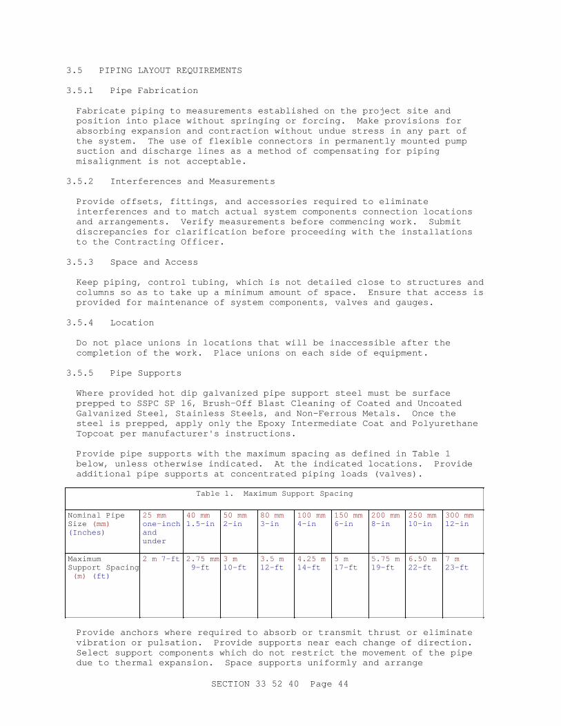
3.5 PIPING LAYOUT REQUIREMENTS
3.5.1 Pipe Fabrication
Fabricate piping to measurements established on the project site and position into place without springing or forcing. Make provisions for absorbing expansion and contraction without undue stress in any part of the system. The use of flexible connectors in permanently mounted pump suction and discharge lines as a method of compensating for piping misalignment is not acceptable.
3.5.2 Interferences and Measurements
Provide offsets, fittings, and accessories required to eliminate interferences and to match actual system components connection locations and arrangements. Verify measurements before commencing work. Submit discrepancies for clarification before proceeding with the installations to the Contracting Officer.
3.5.3 Space and Access
Keep piping, control tubing, which is not detailed close to structures and columns so as to take up a minimum amount of space. Ensure that access is provided for maintenance of system components, valves and gauges.
3.5.4 Location
Do not place unions in locations that will be inaccessible after the completion of the work. Place unions on each side of equipment.
3.5.5 Pipe Supports
Where provided hot dip galvanized pipe support steel must be surface prepped to SSPC SP 16, Brush-Off Blast Cleaning of Coated and Uncoated Galvanized Steel, Stainless Steels, and Non-Ferrous Metals. Once the steel is prepped, apply only the Epoxy Intermediate Coat and Polyurethane Topcoat per manufacturer's instructions.
Provide pipe supports with the maximum spacing as defined in Table 1 below, unless otherwise indicated. At the indicated locations. Provide additional pipe supports at concentrated piping loads (valves).
Table 1. Maximum Support Spacing
Nominal Pipe Size (mm) (Inches)
25 mm one-inch and under
40 mm 1.5-in
50 mm 2-in
80 mm 3-in
100 mm 4-in
150 mm 6-in
200 mm 8-in
250 mm 10-in
300 mm 12-in
Maximum Support Spacing (m) (ft)
2 m 7-ft 2.75 mm 9-ft
3 m10-ft
3.5 m 12-ft
4.25 m 14-ft
5 m 17-ft
5.75 m 19-ft
6.50 m 22-ft
7 m 23-ft
Provide anchors where required to absorb or transmit thrust or eliminate vibration or pulsation. Provide supports near each change of direction. Select support components which do not restrict the movement of the pipe due to thermal expansion. Space supports uniformly and arrange
SECTION 33 52 40 Page 44
symmetrically.
3.5.6 Structural Support
Provide supplementary or intermediate steel or other structural members as required for transmission of loads to members forming part of the supporting structure. Piping must not be supported from other piping.
3.5.7 Grade
Where profiles of piping lines are shown on the drawings, grade the line uniformly between changes in slope or direction. Maintain gradient to within 6 mm 1/4-inch over the entire length of pipe. When backfilling has been completed to the top of the pipe, the pipe must be surveyed at each joint, and logged by station number. Submit to the Contracting Officer for approval the survey final elevations before backfilling can continue.
3.5.8 Size Changes
Make changes in pipe size with reducing fittings. Do not use bushings. Make branch connections with butt-welded tees except where the branch is at least two pipe sizes smaller than the run, in which case the branch connection can be made with a forged or seamless branch outlet fitting. The branch outlet fitting must be designed in such a way that the connection can be radiographed. The branch outlet fittings may be a non-radiographicable if: the piping it is connected to is aboveground, the branch outlet size is 65 mm 2.5 inches or less in diameter, and the branch outlet is located either in a pumphouse or on a system component pad equipped with containment curb.
3.5.9 Direction Changes
Make changes in direction of pipes with 1.5 D fittings. Where piping is to be piggable, make changes in direction with 1.5 D fittings [and][or] 3 D sweeps as indicated. For piggable pipelines, do not place 1.5 D fittings back to back.Provide special fittings when required. Make odd-angle offsets with pipe bends or elbows cut to the proper angle. Make changes in direction with fittings, except that bending of pipe 100 mm 4 inches and smaller will be permitted, provided a pipe bender is used and wide sweep bends are formed. Mitering or notching pipe or other similar construction to form elbows or tees will not be permitted. The centerline radius of bends must not be less than 6 diameters of the pipe if a pipe bender is used.
3.5.10 Threaded End Connections
**************************************************************************NOTE: As st at ed pr evi ousl y, avoi d t hr eaded end connect i ons i f possi bl e. Thr eaded end connect i ons may be used i n cer t ai n abovegr ound appl i cat i ons i f speci f i cal l y i ndi cat ed on t he dr awi ngs. As st at ed pr evi ousl y, never r equi r e a t hr eaded end connect i on t o be di r ect bur i ed.
**************************************************************************
Provide threaded end connections only on piping 50 mm 2 inches in nominal size or smaller and only where indicated on the drawings. Provide threaded connections with PTFE tape or equivalent thread-joint compound applied to the male threads only. Not more than three threads must show
SECTION 33 52 40 Page 45
after the joint is tightened.
3.5.11 Existing Pipe Systems
**************************************************************************NOTE: Del et e t hi s par agr aph i f connect i ons t o exi st i ng pi pi ng syst ems ar e not r equi r ed. I ndi cat e on t he dr awi ngs t he appr oxi mat e l ocat i on of each connect i on poi nt bet ween new and exi st i ng pi pi ng systems.
**************************************************************************
No interruptions or isolation of an existing fuel handling service or system may be performed unless the actions are appropriately documented in the approved work plan. Perform initial cutting of existing fuel pipe with a multiwheel pipe cutter, using a nonflammable lubricant. After cut is made, seal interior of piping with a gas barrier plug. Refer to API RP 2009 and API RP 2200 . Purge interior of piping with carbon dioxide or nitrogen prior to performing any welding process.
3.5.12 Bolted Connections
For each bolted connection of stainless steel components (e.g., pipes, piping components, valves, and system components) use stainless steel bolts or studs, nuts, and washers. For each bolted connection of carbon steel components, use carbon steel bolts or studs, nuts, and washers. Bolts project no more than three full threads and no less than two full threads beyond the nuts with the bolts tightened to the required torque. Prior to installing nuts, apply a compatible anti-seize compound to the male threads.
3.5.13 Flanges and Unions
Except where threaded end connections [and][or] unions are indicated, provide flanged joints in each line immediately preceding the connection to system components or material requiring maintenance such as pumps, general valves, control valves, strainers, and other similar items and as indicated. Assemble flanged joints square and tight with matched flanges, gaskets, and bolts.
3.5.14 Flange Protector
**************************************************************************NOTE: See Not e on FLANGE PROTECTORS par agr aph i n t hi s sect i on.
**************************************************************************
Provide flange protectors [on each electrically insulating flange connection][on each flanged end connection, including valves and system components][where indicated on the drawings].[ Fill the flange cavity of electrically insulating flange connections with a corrosion inhibitor type grease.] Provide grease filled bolt caps.
3.5.15 Manual Valves
**************************************************************************NOTE: Show on t he dr awi ngs doubl e bl ock and bl eed pl ug val ves i nst al l ed upst r eam of each pump st r ai ner as wel l as downst r eam of each f i l t er separ at or
SECTION 33 52 40 Page 46

cont r ol val ve.**************************************************************************
Install isolation plug or ball valves on each side of each system equipment, at the midpoint of looped mains, and at any other points indicated or required for draining, isolating, or sectionalizing purpose. Install valves with stems vertically up unless otherwise indicated. Provide individual supports and anchors for each valve.
3.5.16 Air Vents
Provide [_____] [40 mm] [1-1/2 inches] air vents at all high points and where indicated to ensure adequate venting of the piping system.
3.5.17 Drains
Provide [_____] [50 mm] [2 inches] drains at all low points and where indicated to ensure complete drainage of the piping. Drains must be schedule 120.
3.5.18 Bellows Expansion Joints
Cold set joints to compensate for the temperature at the time of installation. Provide initial alignment guides on the connecting piping no more than 4 pipe diameters from the expansion joint. Provide additional alignment guides on the connecting piping no more than 14 pipe diameters from the first guide.
3.5.19 Thermometers
Provide thermometers with separable sockets. Install separable sockets in pipelines in such a manner to sense the temperature of flowing fluid and minimize obstruction to flow.
3.5.20 Pipe Sleeves
Provide a pipe sleeve around any pipe that penetrates a wall, floor, or slab. Do not install sleeves in structural members except where indicated or approved. Install pipe sleeves in masonry structures at the time of the masonry construction. Sleeves must be of such size as to provide a minimum of 12 mm 1/2-inch all-around clearance between bare pipe and the sleeve. Align sleeve and piping such that the pipe is accurately centered within the sleeve by a nonconductive centering element. Securely anchor the sleeve to prevent dislocation. Closure of the space between the pipe and the pipe sleeve must be by means of a mechanically adjustable segmented elastomeric seal. The seal must be installed so as to be flush. For wall or floor penetrations, extend each sleeve through its respective wall or floor and cut flush with each surface. Seal around sleeves that penetrate through valve or fuel related pits with a Buna-N casing seal. Seal around sleeves that penetrate through non-fire-rated walls and floors in accordance with Section 07 92 00 JOINT SEALANTS. Seal around sleeves that penetrate through fire-rated walls and floors as specified in Section 07 84 00 FIRESTOPPING.
3.5.21 Escutcheons
Except for utility or equipment rooms, provide finished surfaces where exposed piping pass through floors, walls, or ceilings with escutcheons. Secure escutcheon to pipe or pipe covering.
SECTION 33 52 40 Page 47
3.6 SEISMIC REQUIREMENTS
**************************************************************************NOTE: I ncl ude appl i cabl e sei smi c desi gn r equi r ement s on t he dr awi ngs. Del et e t hi s par agr aph i f t her e ar e no speci f i c sei smi c desi gn r equi r ement s.
**************************************************************************
Support and brace piping and attach valves to resist seismic loads as specified under Sections 13 48 00 [SEISMIC ]BRACING FOR MISCELLANEOUS EQUIPMENT[, 22 05 48.00 20 MECHANICAL SOUND, VIBRATION, AND SEISMIC CONTROL] and as shown on the drawings. Structural steel required for reinforcement to properly support piping, headers, and system components but not shown must be provided under this section. Material used for support must be as specified under Section 05 12 00 STRUCTURAL STEEL.
3.7 STRUCTURAL ATTACHMENTS
Provide attachment to building structure concrete and masonry by cast-in concrete inserts, built-in anchors, or masonry anchor devices. Apply inserts and anchors with a safety factor not less than 5. Do not attach supports to metal decking. Construct masonry anchors for overhead applications of ferrous materials only. Structural steel brackets required to support piping, headers, and system components, but not shown, must be provided under this section. Material used for support must be as specified under Section 05 12 00 STRUCTURAL STEEL.
3.8 WELDING
3.8.1 General
All joints, unless indicated otherwise, in carbon steel and stainless steel piping systems must be welded. Do not weld carbon steel to stainless steel. Welding of fuel pipe joints must comply with Section 33 52 23.15 POL SERVICE PIPING WELDING.
3.9 INSTALLATION
3.9.1 Precautions
Take special care to ensure that the protective coating on buried pipe is not damaged during installation and that the completed system is free of rocks, sand, dirt, water, weld slag, and foreign objects including construction debris. Take the following steps to ensure these conditions.
a. Coated pipe must be handled only with canvas or nylon slings or padded clamps. Any coating damaged by improper handling or storage must be repaired as specified.
b. Pipe brought to the site must be stored on blocks or horses at least 450 mm 18 inches above the ground and adequately supported to prevent sagging. Padded blocks or horses must be used for coated pipe. The method and height of storing coated pipe must be in accordance with the coating manufacturer's instructions. Pipe ends must be protected and capped against weather at all times, except to accommodate immediate installation.
c. Visual inspection must be made of the inside of each length of pipe to
SECTION 33 52 40 Page 48
ensure that it is clear and clean prior to installation.
d. The open ends of the pipe system must be closed at the end of each day's work or when work is not in progress by use of expansion plugs and must not be opened until the work is resumed.
e. A swab, with a leather or canvas belt disc to fit the inside diameter of pipe, must be pulled through each length of pipe after welding in place.
f. Obstruction remaining in the pipe after completion of the system must be removed at the expense of the Contractor.
g. Plasma cutters and torches are not to be used to make penetrations in the pipe or to cut pipe.
**************************************************************************NOTE: Sel ect opt i on f or swab pi g r un i f l i ne i s piggable.
**************************************************************************
h. After installation and backfill of the piggable piping is complete and before fuel is put in the pipe, the pipe will be cleaned per the paragraph[s] [CLEANING PIG RUN][WIRE BRUSH RUN] [CLEANING PIG RUN and WIRE BRUSH RUN] in this Section.
3.9.2 Protective Coatings for Buried Piping Including Stainless Steel Piping
3.9.2.1 Application of Coating System
Application of coating system must be in accordance with 33 52 80 LIQUID FUELS PIPELINE COATING SYSTEMS.[ Application of coating system must be in accordance with 09 97 13.27 EXTERIOR COATING OF STEEL STRUCTURES.]
3.9.2.2 Inspection and Testing
The condition of factory field coated piping must be the responsibility of the Contractor and all damage to the protective covering during transit and handling must be repaired at no additional cost to the Government. All field coating must be subject to approval by the Contracting Officer. The entire pipe must be inspected as specified in sub-paragraph TESTING OF PROTECTIVE COATINGS under paragraph PROTECTIVE COATINGS FOR BURIED STEEL PIPING. The inspection for holidays must be performed just prior to lowering the pipe into the ditch and every precaution must be taken during lowering and backfilling to prevent damage to the protective covering.
3.9.2.3 Damage Repair
Damaged areas of coating must be repaired as specified in the preceding paragraph for fittings.
3.10 INTERIOR EPOXY COATING
When internally epoxy lined pipe is cut, the lining must be ground back from the end a minimum of 25 mm one-inch but not more than 38 mm 1-1/2 inches .
SECTION 33 52 40 Page 49
3.11 INSTALLATION OF UNDERGROUND PIPE
Underground fuel pipelines must be pitched as shown on the drawings. Where not indicated they must be pitched a minimum of 50 mm 2 inches per 30.5 m 100 feet . 50 mm Two-inch pipe size valved drain connections must be provided at all low points and 38 mm 1-1/2-inch pipe size valved outlet vent connections must be provided at all high points. Vent and drain lines must terminate in male cam-type locking end connectors with matching female dust covers and installed in pits. The pipe must have cover as shown on the drawings. Drain lines must be installed at the slopes indicated.
3.11.1 Pipe Assembly
Pipe must be strung parallel and adjacent to or above a trench. The pipe must be supported on padded skids during welding and inspection of joints. Protective coating must be inspected and repaired prior to lowering the pipe into the trench. The pipe must be lowered using only canvas or nylon slings. The sling must be dug from underneath the pipe after placements and must not be pulled from underneath the pipe while in contact with it. Care must be taken to prevent damage to the pipe, welded joints or coating and any such damage must be repaired as directed by the Contracting Officer. Pressure testing of the pipe must be done after it has been placed in final position in the trench.
3.11.2 Warning Tapes in Earth Trenches
For the purpose of early warning and identification of buried pipes outside of building walls during future trenching or other excavation, continuous identification tapes must be provided in the trench. Provide metallic core or metallic-faced, acid- and alkali-resistant, polyethylene plastic warning tape manufactured for the purpose of early warning and identification of utilities buried below the tape. Tape must be at least 80 mm 3 inches in width. Color of tape must be as standard with the manufacturer with respect to the type of utility buried below the tape. Tape must have lettering at least 25 mm one-inch high with warning and identification imprinted in bold black letters continuously over the entire tape length with not less than the following identification on the tape: BURIED JET FUEL PIPING BELOW. Tape must be installed in accordance with the printed recommendations of the tape manufacturer, as modified herein. Tapes must be buried at a depth of 150 mm 6 inches from the top of the subgrade or 300 mm 12 inches below the top surface of earth. Provide permanent color and printing, unaffected by moisture or soil.
3.11.3 Clearances
Install pipe to be clear of contact with other pipes, pipe sleeves, casings, reinforcing steel, conduits, cables, or other metallic structures. Where pipes cross other pipes or structures with a separation of less than 150 mm 6 inches , install an insulating separator. Protect the pipe from contact with a 300 mm 12-inch square by 25 mm one-inch thick bituminous-impregnated canefiber board.
3.11.4 Protective Coating
When the protective coating on pipe is damaged, the Contracting Officer must be notified and must inspect the pipe before the coating is patched. If the damage to the pipe is deeper than 1.2 mm 0.050-inch , the damage must be repaired by welding in accordance with paragraph WELDING. If the
SECTION 33 52 40 Page 50
pipe is dented, out of round or damaged to the point that welding will not make it good as new, the length of pipe must be rejected.
3.11.5 Pipe Casing
**************************************************************************NOTE: Desi gn casi ng vent s t o pr event t he i nf l ux of r ai n or gr oundwat er i nt o t he casi ng.
The use of casi ngs on under gr ound pi pel i nes i s hi ghl y di scour aged due t o i ncr ease pr obl ems wi t h pi pe cor r osi on and i nabi l i t y t o pr ovi de cat hodi c pr ot ect i on t o t he pi pe i n t he s l eeve. Use st eel casi ng sl eeves onl y f or t hose cr ossi ngs wher e sl eeves ar e r equi r ed by aut hor i t i es havi ng j ur i sdi ct i on ( i . e. : Ai r f i el d Manager s) , or wher e i t i s necessar y t o pl ace st ai nl ess st eel l i nes bor e under t he r oadway or r ai l r oad t r acks t o whi l e avoi di ng i nt er f er ence wi t h t r af f i c , or wher e bor i ng i s t he most economi cal const r uct i on met hod. Consi der i nst al l i ng car bon st eel and st ai nl ess st eel pi pel i nes under r oadways by t he t r adi t i onal t r enchi ng met hod, or use al t er nat i ve t r enchl ess pi pe const r uct i on met hods f or car bon st eel pi pel i nes t o avoi d t he need f or a casi ng. Do not use di r ect i onal dr i l l i ng f or st ai nl ess st eel l i nes. When usi ng al t er nat i ve t r enchl ess met hods f or car bon st eel l i nes, pr ovi de suppl ement al abr asi on r esi st ant coat i ngs appl i ed i n addi t i on t o t he f usi on bonded epoxy ext er i or pi pe coat i ng. When r equi r ed t o const r uct pl anni ng const r uct i on of open t r ench cased cr ossi ngs, consi der t he economi cs of i nst al l i ng spar e casi ng sl eeves t o el i mi nat e excavat i ng f or f ut ur e f uel l i nes.
Locat e cr ossi ngs at a mi ni mum dept h of 36 i nches ( 900 mm) beneat h t he bot t om of dr ai nage di t ches. I f t hi s dept h cannot be obt ai ned, i nst al l above, but not i n cont act wi t h, t he casi ng or pi pe, a 6- i nch ( 150 mm) t hi ck r ei nf or ced concr et e s l ab of adequat e l engt h and wi dt h t o pr ot ect t he casi ng or pi pe f r om damage by equi pment such as di t ch gr ader s and mower s.
I n ar eas wi t h hi gh nor mal or seasonal gr oundwat er t abl es consi der t he use of a wat er excl udi ng casi ng f i l l mat er i al . Ref er t o API RP 1102 f or addi t i onal i nf or mat i on on t he use of casi ngs.
**************************************************************************
Casing must be continuous for the entire crossing as well as extend a minimum of 150 mm 6 inches beyond both sides of the crossing. Casings must be of such size as to provide a minimum of 12 mm 1/2-inch all-around clearance between bare pipe and the casing. Alignment of the casing and piping must be such that the pipe is accurately centered within the casing by nonconductive centering spacers properly spaced in the casing, and within 300 mm 12 inches of casing ends. Provide seals at each end of the casing. Include a vent on the higher end of each casing and a low point drain on the lower end of the casing. Ensure that the casing design electrically isolates fuel-carrying pipes from contact with the casing
SECTION 33 52 40 Page 51
pipes. Provide cathodic protection test leads to the pipe and casing to monitor for electrical isolation.[ Fill casing with water excluding casing fill material]
3.11.6 Pipeline Markers
Provide above underground fuel piping spaced every 90 meters 300 feet , at tees, and at changes in direction. For sections of underground piping less than 90 meters 300 feet long, place at midpoint. Provide directly above pipe for single lines and between pipes where pipes run in pairs. Provide additional marker over each mid-line fitting connections for steel reinforced flexible pipe. Cast marker into 450 mm 18-inch diameter, 300 mm 12-inch thick concrete plug unless it is set in an area with concrete paving in which case it must be cast into the concrete paving.
3.11.7 Steel Reinforced Flexible Pipe
**************************************************************************NOTE: St eel r ei nf or ced f l exi bl e pi pe comes i n r eel s. To t he ext ent possi bl e, desi gn pi pi ng syst em such t hat t he ent i r e l engt h of under gr ound pi pi ng can be accommodat ed wi t h one r eel .
**************************************************************************
Connections between steel pipe and steel reinforced flexible pipe and between separate lengths of steel reinforced flexible pipe must not be made aboveground but must be made either inside a pit or vault, or direct bury them. Where practicable, end-line and mid-line connections must be located inside pit type enclosures of an appropriate size. Where it is not practicable to locate mid-line connections inside pit type enclosures, mid-line connections may be wrapped with a suitable waterproof protective substance and direct buried underground. The location of direct buried mid-line connections must be indicated on the final drawings and provided with a pipeline marker and monitoring well. Record GPS coordinates of all installed direct buried joints on as-built drawings.
3.12 SYSTEM COMMISSIONING
Conform to Section 33 08 55 FUEL DISTRIBUTION SYSTEM START-UP (NON-HYDRANT).
3.13 TESTING
**************************************************************************NOTE: Hydr ost at i c t est i ng wi t h wat er r equi r es expl i c i t , wr i t t en Ser vi ce Headquar t er s appr oval except i n t he case of f uel pi pi ng syst ems cont ai ni ng f uel s wi t h a f l ash poi nt of l ess t han 38 degr ees C 100 degr ees F ( i . e. JP- 4, Mogas, Avgas, et c. ) ; wi t hout t hat appr oval , hydr ot est i ng wi t h wat er i s f or bi dden. Pr essur e t est i ng of new Mogas, Avgas, and JP- 4 pi pel i nes must be wi t h wat er .
**************************************************************************
Piping must be tested by pneumatic and hydrostatic pressure. Testing must comply with applicable requirements of ASME B31.3 , NFPA 30 and the requirements specified herein. Hydrostatic testing must be performed using [fuel] [water] as the liquid[ with Service Headquarters approval]. Pressure and hydrostatic testing must be performed only after welding
SECTION 33 52 40 Page 52
inspection has been completed. Labor, materials, equipment, electricity, repairs, and retesting necessary for any of the tests required herein must be furnished by the Contractor. Provide provisions to prevent displacement of the piping during testing. Keep personnel clear of the piping during pneumatic testing. Only authorized personnel must be permitted in the area during pneumatic and hydrostatic testing. Isolate system components such as pumps, tanks, filter separators, and meters from the piping system during the testing. Do not exceed the pressure rating of any component in the piping system during the testing. Following satisfactory completion of each test, relieve the test pressure and seal the pipe immediately.[ When water is authorized for hydrostatic testing [and] [or] pigging of fuel piping, ensure that all water is removed from the piping by a combination of pigging the piping, followed by dehydrating the line either with dehumidified air or vacuum extraction. Verification of pipeline dehydrating must be confirmed by measuring dew point of exhausted air. Do not allow water to remain in piping for more than 48 hours after testing. Schedule hydrotesting such that the pipeline can be filled with fuel as soon as possible (no more than two weeks) after testing is complete as it is nearly impossible to assuredly remove all water and corrosion can occur if the time to fuel introduction is extended. The Contractor must submit the piping dehydration test prior to filling pipelines with fuel.] Piping to be installed underground must not receive field applied exterior coatings at the joints or be covered by backfill until the piping has passed the final pneumatic tests described herein.
3.13.1 Before Backfilling
Fuel piping must not be backfilled without completing the coating, pneumatic, weld radiograph and other piping examinations and approvals. Fuel piping in trench must not have exposed welds for longer than 30 days.
3.13.1.1 Exterior Coating Holiday Test
Following installation, test the exterior coating of direct buried piping for holidays using high-voltage spark testing in accordance with NACE SP0188. Repair holidays and retest to confirm holiday-free coating. Text must include all existing underground piping exposed for this project.
3.13.2 Pneumatic Test
Piping to be installed underground must not receive field applied protective covering at the joints or be covered by backfill until the piping has passed the pneumatic test described herein. To facilitate the tests, isolate various sections of the piping system and test each one separately. Where such sections terminate at flanged valve points, the line must be closed by means of blind flanges in lieu of relying on the valve. Furnish tapped flanges that can be attached to the end of the section of line being tested, and that will permit a direct connection between the piping and the air compressor [and][or] pressurizing pump. No taps in the permanent line will be permitted. Furnish all necessary equipment for testing; all gauges must be subject to testing and approval of the Contracting Officer. The air used for pneumatic testing must have a dew point of no more than 5 degrees C 41 degrees F . Provide dehumidifying equipment on the suction or discharge side of the air compressor used to provide air for testing. Pressurizing pump must not exceed 4.7 L/s 10 cfm .
SECTION 33 52 40 Page 53
3.13.2.1 Pneumatic Test Procedure
**************************************************************************NOTE: Use 50 psi g f i nal t est pr essur e unl ess per mi ssi on t o go hi gher i s secur ed f r om t he Ser vi ce Headquar t er s and t he Cont r act i ng Of f i cer .
**************************************************************************
Special safety measures, including the wearing of face mask, must be taken during testing under pressure. Only authorized personnel must be permitted in the area during testing. The pneumatic test pressure must be applied in increments. A preliminary 167 kPa 25 psig test must be applied. Maintain the pressure while soapsuds or equivalent materials are applied to the exterior of the piping. While applying the soapsuds, visually inspect the entire run of piping, including the bottom surfaces, for leaks (bubble formations). If leaks are discovered, repair the leaks accordingly and retest. Repeat process until system is leak-free at 25 psig. The full test pressure must then be applied. Unless otherwise directed by the Contracting Officer, all piping must be tested at a pressure of [667] [333] kPa [50] [100] psig for not less than 2-hours, during which time there must be no drop in pressure, only pressure rises with temperature. The pressure source must be disconnected during the final test period. Any leaks revealed by the test must be repaired and the test repeated.
3.13.3 Hydrostatic Test
**************************************************************************NOTE: Unl ess ot her wi se di r ect ed by t he Ser vi ce Headquar t er s, hydr ost at i cal l y t est abovegr ound pi pi ng syst ems t o t he maxi mum al l owabl e wor ki ng pr essur e of t he ASME B16. 5 pi pi ng syst em f l anges at 38 degr ees C 100 degr ees F and hydr ost at i cal l y t est under gr ound pi pi ng syst ems t o 1. 5 t i mes t he maxi mum al l owabl e wor ki ng pr essur e of t he ASME B16. 5 pi pi ng syst em f l anges at 38 degr ees C 100 degr ees F. Ref er t o UFC 3- 460- 01 f or mor e gui dance.
Hydr ost at i cal l y t est i ng t he syst em t o 1. 5 t i mes t he f l ange r at i ng, wi l l r equi r e t he desi gner t o wr i t e t he commi ssi oni ng hydr ost at i c t est i ng pr ocedur es, whi ch wi l l consi der t he r emoval of syst em component s ( i . e. : bal l val ves, cont r ol val ves, met er s) , and pr ovi de pr ocedur es of t he hydr ost at i c t est whi ch shoul d i ncl ude what val ves t o c l ose, wher e t o i nst al l t he hydr ost at i c t est pump, bl i nd f l ange pl acement s, hi gh poi nt vent s and l ow poi nt dr ai ns, and ot her r equi r ement s.
NOTE: Hydr ost at i c t est i ng wi t h wat er r equi r es expl i c i t , wr i t t en Ser vi ce Headquar t er s appr oval except i n t he case of f uel pi pi ng syst ems cont ai ni ng f uel s wi t h a f l ash poi nt of l ess t hat 38 degr ees C 100 degr ees F ( i . e. JP- 4, Mogas, Avgas, et c. ) ; wi t hout t hat appr oval , hydr ot est i ng wi t h wat er i s forbidden.
NOTE: I f hydr ost at i c t est i ng wi t h wat er , per f or m soak t est af t er i ni t i al i nt r oduct i on of f uel as
SECTION 33 52 40 Page 54

descr i bed i n Sect i on 33 08 55 FUEL DI STRI BUTI ON SYSTEM START- UP ( NON- HYDRANT) .
**************************************************************************
Upon completion of pneumatic testing and after backfilling, hydrostatically test each underground piping system with [fuel] [water] at [1.9] [2] [2.9] [3.1] [_____] MPa [275] [285] [425] [450] [_____] psig in accordance with ASME B31.3 and API RP 1110 , with no leakage or reduction in gauge pressure for four hours. Upon completion of pneumatic testing, hydrostatically test each aboveground piping system with fuel at [1.9] [2] [2.9] [3.1] [_____] MPa [275] [285] [425] [450] [_____] psig in accordance with ASME B31.3 and API RP 1110 , with no leakage or reduction in gauge pressure for four hours. Furnish electricity, instruments, connecting devices, and personnel for test.[ Fuel must be furnished by the Government.][ If fuel is used for testing, comply with all the requirements in Section 33 08 55 FUEL DISTRIBUTION SYSTEM START-UP (NON-HYDRANT).][ In cases where it is not specified, water must be potable and treated and must meet all the requirements of water used for hydrostatic testing in API 570.][ Upon completion of hydrostatic testing, perform "Soak Testing" of the piping systems per API RP 1595 . Duration of the test must be a minimum of 4 days and maximum of 7 days.] Defects in work must be corrected at the Contractor's expense, and the test repeated until the work is proven to be in compliance with the Contract requirements.
3.13.4 Soak Testing
**************************************************************************NOTE: Per f or m soak t est af t er i ni t i al r ecei pt of f uel as descr i bed i n Sect i on 33 08 55 FUEL DI STRI BUTI ON SYSTEM START- UP ( NON- HYDRANT) . The t i mi ng of t he i ni t i al r ecei pt of f uel wi l l depend on wher e wat er i s used f or j ust hydr ot est i ng, or hydr ot est i ng and pi ggi ng.
**************************************************************************
[Upon completion of hydrostatic testing with fuel, perform "Soak Testing" of the piping systems per API RP 1595 . Duration of the test must be a minimum of 4 days and maximum of 7 days.] [Upon completion of initial receipt of fuel, perform "Soak Testing" of the piping systems per API RP 1595 . Duration of the test must be a minimum of 4 days and maximum of 7 days.]
3.13.5 Performance Testing
After the fuel system testing is completed (including pneumatic and hydrostatic testing) the fuel system must be flushed, cleaned and performance tested as specified in Section 33 08 55 FUEL DISTRIBUTION SYSTEM START-UP (NON-HYDRANT). All control valves, both manual and automatic, must be checked for leaks (any area wetted with fuel) and proper operation and adjusted, repaired or replaced to correct any defects.
[ 3.14 PIPE PIGGING - CLEANING
**************************************************************************NOTE: Sel ect br acket ed par agr aph i f syst em i s desi gned t o be pi ggabl e. St andar d c l eani ng pi g r uns ar e r ecommended on al l syst ems.
SECTION 33 52 40 Page 55
**************************************************************************
**************************************************************************NOTE: Pi ggi ng wi t h wat er r equi r es expl i c i t , wr i t t en Ser vi ce Headquar t er s appr oval and i s not al l owed i n syst ems whi ch cont ai ned f uel pr evi ousl y.
NOTE: The choi ce of t he f l ui d used t o pr opel c l eani ng pi gs wi l l var y gr eat l y f r om pr oj ect t o project.a. Pneumat i c pr opel l ed c l eani ng pi gs wi l l al most al ways be used bef or e any ot her pi gs ar e r un.b. Wat er pr opel l ed pi gs wi l l be al l owed onl y af t er secur i ng expl i c i t , wr i t t en Ser vi ce Headquar t er s approval.c. Fuel pr opel l ed pi gs may al ways be used.
**************************************************************************
3.14.1 General
**************************************************************************NOTE: I ncl ude br acket ed t ext f or non- st ai nl ess pi pi ng syst ems, or i f excessi ve cont ami nat i on i s anticipated.
**************************************************************************
Track all pigs, using transmitter and receivers, at no less than 805 m 1/2-mile increments, but no less than at four locations. The Contractor must prepare a contingency plan for retrieving a stuck pig and repairing any piping deformations. After pigging, plug valves must be flushed of all debris using the drain port at the bottom of the valve.
[ 3.14.2 Use of Fuel in Cleaning Pigging
Cleaning pigging with fuel will take place after the initial receipt of fuel as per Section 33 08 55 FUEL DISTRIBUTION SYSTEM START-UP (NON-HYDRANT). Ensure that the fuel that is returned to the storage tanks during the pig runs is free of gross contamination and passes the color assessment method, and meets the requirements of MIL-STD-3004-1 . Provide temporary storage tanks for the high particulate and dark color fuel that accumulates in front of and behind each pig. The contractor is responsible for [cleaning the off-spec fuel in order to meet the requirements of MIL-STD-3004-1 ] [,dispose of the off-spec fuel off-base][,obtain permission from the Contracting officer to downgrade the fuel and dispose of it in the appropriate tank].
][ 3.14.3 Use of Water in Cleaning Pigging
Ensure that the water, in cases where it is not specified, must be potable and treated and must meet all the requirements of water used for hydrostatic testing in API 570 . Dispose of the water in accordance with applicable Installation, city, county, state, and federal regulations.
] 3.14.4 Cleaning Pig Run
[Contractor-provided pig launching and receiving barrels must be
installed. ]Initially, a proving pig run (foam density 32 kg/m 3 2 lb/ft 3 should be performed to ensure the system is fully piggable. Upon completion of the successful proving pig run, the piping system must be
SECTION 33 52 40 Page 56
cleaned with a standard cleaning pig. This will provide thorough cleaning of the interior of the piping system. Cleaning pig must be the bi-directional disk scraper style with steel body and replaceable polyurethane guiding and sealing disks, as well as gauge plates of 80 percent pipe diameter with 3 mm 1/8-inch segmented aluminum fins. The pig body should include bypass nozzles and transmitter cavity. Propellant must be pressurized [fuel][water] using [the main system delivery pumps][portable pumps]. The pig must be examined after the initial run for signs of possible pipe damage, interior slag or other adhered particles. Additional runs must be performed until the amount of collected sludge or debris is minimized, as determined by the [Contracting Officer][System Supplier].
3.14.5 Wire Brush Pig Run
**************************************************************************NOTE: Sel ect wi r e br ush cl eani ng pi g opt i on i f excessi ve s l ag or ot her adher ed par t i c l es ar e suspect ed on t he pi pe i nt er i or . Requi r e st ai nl ess st eel br ushes on st ai nl ess st eel pi pi ng syst ems.
Never per f or m wi r e br ush cl eani ng pi g on i nt er i or epoxy coat ed pi pi ng syst ems.
**************************************************************************
After the cleaning pig runs, the piping system must be cleaned with a wire brush style pig. This will remove weld slag and adhered particles from the system. Wire brush pig must be the bi-directional disk style or directional cup style with two circular [stainless] steel wire brushes. The pig body should include bypass nozzles and transmitter cavity. Perform wire brush pig runs until the amount of collected weld slag or debris is minimized, as determined by the [Contracting Officer][System Supplier].
] 3.15 PIPE PIGGING VERIFICATION
**************************************************************************NOTE: Pi ggi ng wi t h wat er r equi r es expl i c i t , wr i t t en Ser vi ce Headquar t er s appr oval and i s not al l owed i n syst ems whi ch cont ai ned f uel pr evi ousl y.
**************************************************************************
[ 3.15.1 Use of Water in Pipe Pigging Verification
Ensure that the water, in cases where it is not specified, must be potable and treated and must meet all the requirements of water used for hydrostatic testing in API 570 . Dispose of the water in accordance with applicable Installation, city, county, state, and federal regulations.
] 3.15.2 Geometry/Ultrasonic Tool Reports
After the system is installed and prior to performance testing, a field/preliminary report must be issued and a debrief given to Government personnel onsite on the condition of the piping system that was pigged. This must be comprised of raw data in the form of a PC download or equivalent which shows a continuous scan of each data unit output. Results of a preliminary interpretation of the data must be reported. These must include as a minimum all critical anomalies. A final report must include a description of the principle of operation, explanation of
SECTION 33 52 40 Page 57
raw data, presentation of raw data, data to be clearly marked with distance traveled scale with classified anomaly location and all identifiable pipeline features, and all anomalies to be classified with locations in summary tabular form, pipe wall thickness survey, as well as the software necessary to read the data. Submittal must be in the form of digital media copied to a CD or DVD (flash drives are unacceptable).
3.15.3 Pipeline Internal Inspection Operations
3.15.3.1 General
The following pigs will be propelled through the pipeline with [fuel][water] in order to inspect the pipeline: 1.7 kg 5 pound density foam swab, combination poly scraper-magnetic, stainless steel wire brush (plastic brush for internally lined piping), aluminum plate gauge, and geometry/ultrasonic tool. Tracking devices must be used on all pigs. At a minimum, the sequence of pig runs must be as follows: 1) foam swab for proving and cleaning, 2) wire brush for cleaning, 3) scraper-magnetic for cleaning, 4) aluminum plate gauge for gauging internal anomalies, 5) scraper-magnetic for cleaning, 6) wire brush for cleaning, 7) scraper-magnetic for cleaning, 8) foam swab for cleaning, (Note: the number of pig flights of each type of cleaning pigs must be determined by the amount and type of debris removed. The conclusion of the cleaning process must be when debris recovered is only that from the pigs themselves. This determination will be determined by the project's System Supplier and the Contracting Officer), 9) geometry/ultrasonic tool. The pipe wall must be continuously monitored on a real-time basis during the geometry/ultrasonic pig run. Anomalies such as patches, couplings, or flanges must also be identified, and the wall thickness given. The geometry/ultrasonic pig's technician will determine if additional runs are necessary. A permanent data set of internal inspection survey findings must be generated.
3.15.3.2 Preparatory Work
The Government will bring to the attention of the Contractor all statutes, rules and regulations relevant to the performance of the work on the site (on Government property) and will also provide the Contractor with a copy of its own site regulations (if any). Provide the pigging vendors with all-available pipeline records and drawings.
3.15.3.3 Pig Load And Launch
**************************************************************************NOTE: I f pi g a l auncher and a r ecei ver ar e not pr ovi ded i n t he cont r act , por t abl e ones wi l l be by t he Cont r act or dur i ng pi ggi ng oper at i ons.
**************************************************************************
The pig must be loaded into the pig launcher by the Contractor. The method of loading and lodging the front pig cup into the launcher must not involve the use of uncontrolled mechanical force applied to the rear of the pig.
3.15.3.4 Pipeline Operation During Pigging
All pig runs must be made with the line packed with product. The system pumps will be used to propel the pig. The new pig traps will be used for pig launch and retrieval.
SECTION 33 52 40 Page 58

3.15.3.5 Brush and Gauging Survey
Run a brush pig at least as often as previously indicated. The brush pig must be designed and provided by the geometry/ultrasonic pig vendor. Additional runs may be required based upon the amount of debris found in the pipeline. The onsite geometry/ultrasonic pig vendor's personnel must determine if additional runs are required. Immediately following the brush pig run and immediately prior to the geometry/ultrasonic survey, run, as a minimum, a single batching pig fitted with a gauge plate equal to 90 percent of the pipeline normal inside diameter. The plate is to be a segmented aluminum disk of 3 mm 1/8-inch thickness. The plate gauge pig must also include a tracker and tracking equipment. Track the pig assembly above ground during the operation.
3.15.3.6 Geometry/Ultrasonic Survey
After a satisfactory gauging pig run, the pipeline geometric defects must be determined by a geometry/ultrasonic tool. The geometry/ultrasonic tool must provide accuracy geometric anomaly detection, and bend radius measuring capability. The data obtained must be presented in a PC software format to allow user friendly analysis and presentation. The geometry/ultrasonic tool assembly must be capable of:
a. Operating in [hydrocarbon liquid environment, specifically [jet fuel][_____]][water], at a pressure of up to ANSI 300 rating.
b. Traversing the pipeline with nominal wall thickness and possible bore restrictions down to 90 percent of nominal pipe inside diameter.
c. Traversing the pipeline length at a speed of between 60 and 100 m/min 3 and 5 ft/sec when propelled by pumped [jet fuel][water]. Pressure differential across pig not to exceed 34 kPa 50 psi .
d. Traversing through smooth pipe bends as small as 3D (3 pipe diameters) radius and single miter bends of up to 10 degrees change of direction.
e. Include a tracker and tracking equipment. Track the pig assembly above ground during the operation. The battery life of the tracker must not be less than 72-hours.
f. Manual loading into the new horizontal pig trap.
The geometry/ultrasonic tool assembly instrumentation performance must be capable of:
a. Battery life to be minimum 18-hours at operating conditions.
b. Principle of operation to be electronically stored geometry system.
c. Geometry sensing to span full circumference and length of pipe, with associated distance measuring method.
d. Geometry system must be capable of:
(1) positive location and identification of each geometric anomaly .
(2) positive location and identification of each bend.
SECTION 33 52 40 Page 59
(3) positive location and identification of distance marker reference points of either magnetic or electronic type placed on or above the pipe.
e. Classification of geometric anomalies to be as minimum:
(1) discrimination between ovality and intrusion anomalies.
(2) mechanical damage such as mill defects, dents, internal gouges, and buckles.
(3) pipeline weld defects (such as excess weld penetration).
(4) geometric thickness anomalies. As a minimum, these must be reported in the following categories within the listed accuracy.
(a) magnitude of anomaly (plus/minus 25 mm one-inch )
(b) span of anomaly (plus/minus 25 mm one-inch )
(c) ovality (plus/minus 2.5 mm 0.1-inch )
(d) span of ovality (plus/minus 25 mm one-inch )
(e) anomaly station (plus/minus 1:2,000)
3.15.3.7 Pipe Wall Thickness Survey
The geometry/ultrasonic tool must provide accuracy measurement of pipe wall thickness (plus/minus 0.25 mm 0.01-inch ). The data obtained must be presented in a PC software format to allow user friendly analysis and presentation.
3.15.3.8 Lost Pig
The Contractor is responsible for a lost pig, finding the pig, retrieval of the pig, and all repairs, radiographs to the pipeline system and the pig.
3.16 DEMONSTRATIONS
As per requirements in Section 33 57 55 FUEL SYSTEM COMPONENTS (NON-HYDRANT).
3.17 POSTED OPERATING INSTRUCTIONS
As per requirements in Section 33 57 55 FUEL SYSTEM COMPONENTS (NON-HYDRANT).
-- End of Section --
SECTION 33 52 40 Page 60