Embed Size (px)
Citation preview

UG0758 User Guide
PolarFire FPGA Design Flow
NOTE: PDF files are intended to be viewed on the printed page; links and cross-references in this PDF file may point to external files and generate an error when clicked. View the online help included with software to enable all linked content.

PolarFire Design Flow User Guide
3
Microsemi makes no warranty, representation, or guarantee regarding the information contained herein or the suitability of its products and services for any particular purpose, nor does Microsemi assume any liability whatsoever arising out of the application or use of any product or circuit. The products sold hereunder and any other products sold by Microsemi have been subject to limited testing and should not be used in conjunction with mission-critical equipment or applications. Any performance specifications are believed to be reliable but are not verified, and Buyer must conduct and complete all performance and other testing of the products, alone and together with, or installed in, any end-products. Buyer shall not rely on any data and performance specifications or parameters provided by Microsemi. It is the Buyer’s responsibility to independently determine suitability of any products and to test and verify the same. The information provided by Microsemi hereunder is provided “as is, where is” and with all faults, and the entire risk associated with such information is entirely with the Buyer. Microsemi does not grant, explicitly or implicitly, to any party any patent rights, licenses, or any other IP rights, whether with regard to such information itself or anything described by such information. Information provided in this document is proprietary to Microsemi, and Microsemi reserves the right to make any changes to the information in this document or to any products and services at any time without notice.
About Microsemi Microsemi Corporation (NASDAQ: MSCC) offers a comprehensive portfolio of semiconductor and system solutions for aerospace & defense, communications, data center and industrial markets. Products include high-performance and radiation-hardened analog mixed-signal integrated circuits, FPGAs, SoCs and ASICs; power management products; timing and synchronization devices and precise time solutions, setting the world's standard for time; voice processing devices; RF solutions; discrete components; enterprise storage and communication solutions; security technologies and scalable anti-tamper products; Ethernet solutions; Power-over-Ethernet ICs and midspans; as well as custom design capabilities and services. Microsemi is headquartered in Aliso Viejo, California, and has approximately 4,800 employees globally. Learn more at www.microsemi.com.
5-02-00758-4/11.17
Microsemi Corporate Headquarters One Enterprise, Aliso Viejo, CA 92656 USA Within the USA: +1 (800) 713-4113 Outside the USA: +1 (949) 380-6100 Fax: +1 (949) 215-4996 Email: [email protected] www.microsemi.com
©2017 Microsemi Corporation. All rights reserved. Microsemi and the Microsemi logo are registered trademarks of Microsemi Corporation. All other trademarks and service marks are the property of their respective owners.

PolarFire Design Flow User Guide
4
Table of Contents
Table of Contents........................................................................................... 4
Libero SoC Introduction ................................................................................ 6 Welcome to Microsemi's Libero® SoC PolarFire™ v2.0 Release .............................................. 6 Libero SoC PolarFire Design Flow ............................................................................................. 7 Constraint Flow and Design Sources ....................................................................................... 10 File Types in Libero SoC .......................................................................................................... 11 Software Tools - Libero SoC .................................................................................................... 13
Libero Design Flow ...................................................................................... 14 Starting the Libero GUI ............................................................................................................ 14 Design Report .......................................................................................................................... 15 Using the New Project Wizard to Start a Project ..................................................................... 15
Create and Verify Design ............................................................................ 21 Create SmartDesign................................................................................................................. 21 Create Core from HDL ............................................................................................................. 22 Designing with HDL.................................................................................................................. 24 Designing with Block Flow ....................................................................................................... 25 SmartDesign Testbench .......................................................................................................... 25 HDL Testbench ........................................................................................................................ 26 Verify Pre-Synthesized Design - RTL Simulation .................................................................... 27
Libero SoC Constraint Management .......................................................... 31 Invocation of Constraint Manager From the Design Flow Window .......................................... 31 Libero SoC Design Flow .......................................................................................................... 31 Introduction to Constraint Manager .......................................................................................... 32 Import a Constraint File ............................................................................................................ 36 Constraint Types ...................................................................................................................... 41 Constraint Manager – I/O Attributes Tab ................................................................................. 42 Constraint Manager – Timing Tab ........................................................................................... 43 Derived Constraints.................................................................................................................. 45 Constraint Manager – Floor Planner Tab................................................................................. 46 Constraint Manager – Netlist Attributes Tab ............................................................................ 47
Implement Design ........................................................................................ 49 Synthesize ................................................................................................................................ 49 Compile Netlist ......................................................................................................................... 53 Resource Usage ...................................................................................................................... 54 Constraint Flow in Implementation ........................................................................................... 55 Place and Route ....................................................................................................................... 59

PolarFire Design Flow User Guide
5
Multiple Pass Layout Configuration ......................................................................................... 63 Verify Post Layout Implementation .......................................................................................... 65
Program and Debug Design ........................................................................ 72 Generate FPGA Array Data ..................................................................................................... 72 Design and Memory Initialization ............................................................................................. 72 Generate Design Initialization Data ......................................................................................... 81 Configure Hardware ................................................................................................................. 82 Configure Programming Options ............................................................................................. 86 Configure Security.................................................................................................................... 87 Program Design ....................................................................................................................... 95 Program SPI Flash Image ...................................................................................................... 104 Debug Design ........................................................................................................................ 107
Handoff Design for Production ................................................................. 108 Export Bitstream ..................................................................................................................... 108 Export FlashPro Express Job ................................................................................................ 111 Export SPI Flash Image ......................................................................................................... 113 Export Pin Report ................................................................................................................... 113 Export BSDL File .................................................................................................................... 114
Export SmartDebug Data (Libero SoC) .................................................... 115
References ................................................................................................. 117

PolarFire Design Flow User Guide
6
Libero SoC Introduction
Welcome to Microsemi's Libero® SoC PolarFire™ v2.0 Release Microsemi's Libero® SoC PolarFire™ software is specifically for designing with PolarFire FPGAs, the fifth generation family of non-volatile FPGA devices from Microsemi, built on state-of-the-art 28nm non-volatile process technology. Cost-optimized PolarFire FPGAs deliver the lowest power at mid-range densities. For documentation about PolarFire FPGAs, see the PolarFire product information page on the Microsemi website. Microsemi's Libero® SoC is a comprehensive and powerful FPGA design and development software suite, providing start-to-finish design flow guidance and support for novice and experienced users alike. Libero SoC combines Microsemi's tools with EDA tools such as Synplify Pro® and ModelSim®.
More Information For more information about the Libero® SoC PolarFire v2.0 release, see the Microsemi Website.
PolarFire Design Flow User Guide
7
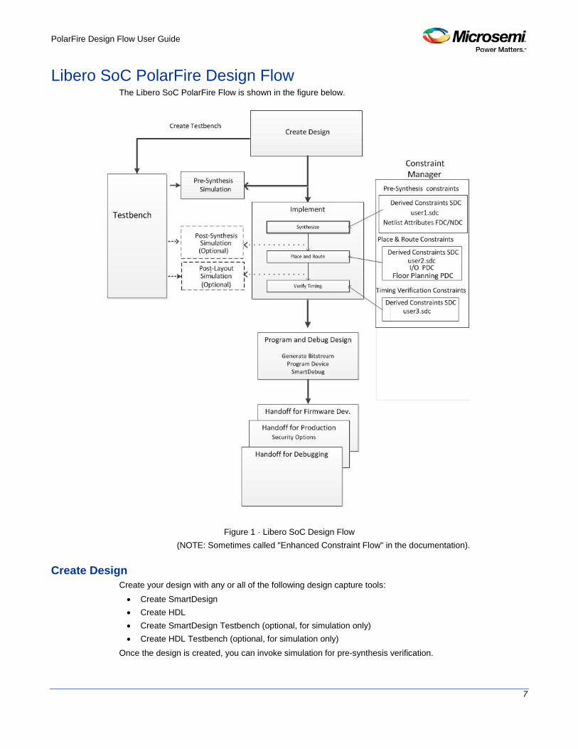
Libero SoC PolarFire Design Flow The Libero SoC PolarFire Flow is shown in the figure below.
Figure 1 · Libero SoC Design Flow
(NOTE: Sometimes called "Enhanced Constraint Flow" in the documentation).
Create Design Create your design with any or all of the following design capture tools: • Create SmartDesign • Create HDL • Create SmartDesign Testbench (optional, for simulation only) • Create HDL Testbench (optional, for simulation only)
Once the design is created, you can invoke simulation for pre-synthesis verification.
PolarFire Design Flow User Guide
8
It is also possible to click the button, to execute the Libero SoC software from Synthesis (for HDL flow) or Compile Netlist (for EDIF flow) through Place and Route with default settings. However this bypasses constraint management.
Constraints
Manage Constraints
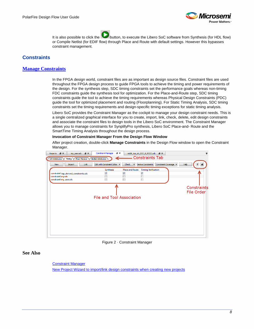
In the FPGA design world, constraint files are as important as design source files. Constraint files are used throughout the FPGA design process to guide FPGA tools to achieve the timing and power requirements of the design. For the synthesis step, SDC timing constraints set the performance goals whereas non-timing FDC constraints guide the synthesis tool for optimization. For the Place-and-Route step, SDC timing constraints guide the tool to achieve the timing requirements whereas Physical Design Constraints (PDC) guide the tool for optimized placement and routing (Floorplanning). For Static Timing Analysis, SDC timing constraints set the timing requirements and design-specific timing exceptions for static timing analysis. Libero SoC provides the Constraint Manager as the cockpit to manage your design constraint needs. This is a single centralized graphical interface for you to create, import, link, check, delete, edit design constraints and associate the constraint files to design tools in the Libero SoC environment. The Constraint Manager allows you to manage constraints for SynplifyPro synthesis, Libero SoC Place-and- Route and the SmartTime Timing Analysis throughout the design process. Invocation of Constraint Manager From the Design Flow Window After project creation, double-click Manage Constraints in the Design Flow window to open the Constraint Manager.
Figure 2 · Constraint Manager
See Also
Constraint Manager New Project Wizard to import/link design constraints when creating new projects

PolarFire Design Flow User Guide
9
Implement Netlist Viewer User Guide
Synthesize Double-click Synthesize to run synthesis on your design with the default settings. The constraints associated with Synthesis in the Constraint Manager are passed to Synplify.
Place and Route Place and Route takes the design constraints from the Constraint Manager and runs with default settings.
This is the last step in the push-button design flow execution.
Verify Post Layout Implementation • Verify Timing - Right click and select Configure Options to specify a timing report with your desired
conditions. • Open SmartTime • Verify Power
Program and Debug Design Generate FPGA Array Data
Design and Memory Initialization
Configure Hardware • Programming Connectivity and Interface - Organizes your programmer(s) and devices. • Configure Programmer - Opens your programmer settings; use if you wish to program using settings
other than default. • Device I/O States During Programming - Sets your device I/O states during programming; use if
your design requires that you change the default I/O states.
Configure Programming Options
Configure Security Wizard
Program Design • Generate Bitstream • Run PROGRAM Action
Debug Design • SmartDebug (User Guide)

PolarFire Design Flow User Guide
10
Handoff Design for Production Export Bitstream
Export SPI Flash Image
Export FlashPro Express Job
Export Pin Report
Export BSDL
Handoff Design for Debugging (Export SmartDebug Data)
Constraint Flow and Design Sources The Constraint Flow supports HDL and EDIF design sources. The Libero SoC Design Flow window and the Constraint Manager are context-sensitive to the type of design sources: HDL or EDIF.
Constraint Flow for HDL designs When the design source is HDL, the Design Flow window displays Synthesis as a design step. The Constraint Manager also makes available Synthesis as a target to receive timing constraints and netlist attribute constraints. The options to promote or demote global resources of the chip are set in the Synthesis options.
Constraint Flow for EDIF designs When the design source is EDIF/EDN, the Design Flow window displays Compile Netlist as a design step. Timing constraints can be passed to Place and Route and Timing Verification only. The options to promote or demote global resources of the chip are set in the Compile Netlist options. The HDL flow versus the EDIF Flow is compared and contrasted below.
HDL Flow EDIF Flow
Design Flow Window
Design Flow Window

PolarFire Design Flow User Guide
11
HDL Flow EDIF Flow
Constraint Manager
Constraint Manager
Constraint Manager - Check *.fdc and *.ndc
Constraint Manager - Check *.ndc only
Global Promotion/Demotion Options set in Synthesis Options Dialog Box
Global Promotion/Demotion Options set in Compile Netlist Options Dialog Box
Figure 3 · HDL vs. EDIF Flow
File Types in Libero SoC When you create a new project in Libero SoC it automatically creates new directories and project files. Your project directory contains all of your local project files. When you import files from outside your current project, the files are copied into your local project folder. The Project Manager enables you to manage your files as you import them. If you want to store and maintain your design source files and design constraint files in a central location outside the Project location, Libero gives you the option to link them to your Libero project folders when you first create your project. These linked files are not copied but rather linked to your project folder. Depending on your project preferences and the version of Libero SoC you installed, the software creates directories for your project. The top level directory (<project_name>) contains your *.prjx file; only one *.prjx file is enabled for each Libero SoC project. If you associate Libero SoC as the default program with the *.prjx file (Project > Preferences > Startup > Check the default file association (.prjx) at startup), you can double-click the *.prjx file to open the project with Libero SoC. component directory - Stores your SmartDesign components (SDB and CXF files) and the *_manifest.txt file for each design components in your Libero SoC project. Refer to the *_manifest.txt file if you want to run synthesis, simulation, and firmware development with your own point tools outside the Libero SoC

PolarFire Design Flow User Guide
12
environment. For each design component, Libero SoC generates a <component_name>_manifest.txt file which stores the file name and location of: • HDL source files to be used for synthesis and simulations • Stimulus files and configuration files for simulation • Firmware files for software IDE tools • Configuration files for programming • Configuration files for power analysis.
constraint directory - All your constraint files (SDC timing constraint files, floorplanning PDC files, I/O PDC files, Netlist Attributes NDC files) designer directory - *_ba.sdf, *_ba.v(hd), STP, PRB (for Silicon Explorer), TCL (used to run designer), impl.prj_des (local project file relative to revision), designer.log (logfile) hdl directory - all hdl sources. *.vhd if VHDL, *.v and *.h if Verilog simulation directory - meminit.dat, modelsim.ini filesfiles and *.vec file, run.do file for simulation. smartgen directory - GEN files and LOG files from generated cores stimulus directory - BTIM, Verilog, and VHDL stimulus files synthesis directory - *.edn, *_syn.prj (Synplify log file), *.psp (Precision project file), *.srr (Synplify logfile), precision.log (Precision logfile), *.tcl (used to run synthesis) and many other files generated by the tools (not managed by Libero SoC) viewdraw directory - viewdraw.ini files
Internal Files Libero SoC generates the following internal files. They may or may not be encrypted. They are for Libero SoC housekeeping and are not for users.
File File Extension Remarks
Routing Segmentation File *.seg
Combiner Info *.cob
Hierarchical Netlist *.adl
Flattened Netlist *.afl
map file *.map Fabric Programming File

PolarFire Design Flow User Guide
13
Software Tools - Libero SoC The Libero SoC integrates design tools, streamlines your design flow, manages design and log files, and passes design data between tools. For more information on Libero SoC tools, visit: https://www.microsemi.com/products/fpga-soc/design-resources/design-software/libero-soc#overview
Function Tool Company
Project Manager, HDL Editor, Core Generation Libero SoC Microsemi SoC
Synthesis Synplify® Pro ME Synopsys
Simulation ModelSim® ME Pro Mentor Graphics
Timing/Constraints, Power Analysis, Netlist Viewer, Floorplanning, Package Editing, Place-and-Route
Libero SoC Microsemi SoC
Project Manager, HDL Editor targets the creation of HDL code. HDL Editor supports VHDL and Verilog with color, highlighting keywords for both HDL languages. Synplify Pro ME from Synopsys is integrated as part of the design package, enabling designers to target HDL code to specific devices. Microsemi SoC software package includes: • Chip Planner displays I/O and logic macros in your design for floorplanning • Netlist Viewer design schematic viewer • SmartPower power analysis tool • SmartTime static timing analysis and constraints editor
ModelSim ME Pro from Mentor Graphics enables source level verification so designers can verify HDL code line by line. Designers can perform simulation at all levels: behavioral (or pre-synthesis), structural (or post-synthesis), and back-annotated (post-layout), dynamic simulation. (ModelSim ME Pro is supported in Libero Gold and Platinum only.)
PolarFire Design Flow User Guide
14
Libero Design Flow
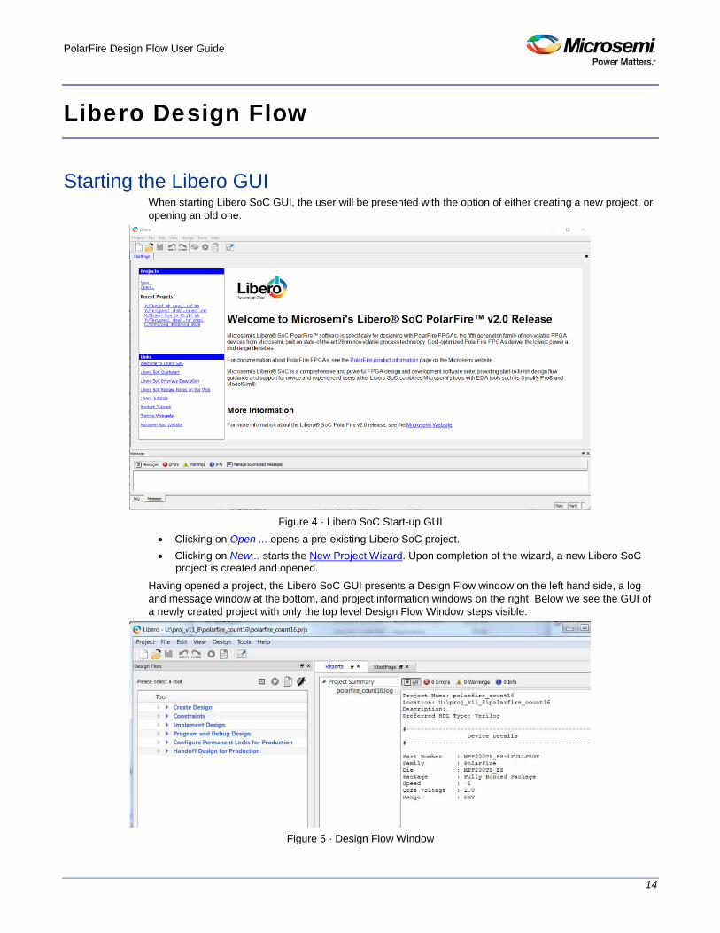
Starting the Libero GUI When starting Libero SoC GUI, the user will be presented with the option of either creating a new project, or opening an old one.
Figure 4 · Libero SoC Start-up GUI
• Clicking on Open ... opens a pre-existing Libero SoC project. • Clicking on New... starts the New Project Wizard. Upon completion of the wizard, a new Libero SoC
project is created and opened. Having opened a project, the Libero SoC GUI presents a Design Flow window on the left hand side, a log and message window at the bottom, and project information windows on the right. Below we see the GUI of a newly created project with only the top level Design Flow Window steps visible.
Figure 5 · Design Flow Window

PolarFire Design Flow User Guide
15
The Design Flow Window The Design Flow Window for each technology family may be slightly different. The Constraint Flow choice made during new project creation may also affect the exact elements of design flow. However, all flows include some version of the following design steps: • Create • Constrain • Implement
Design Report The Design Report Tab lists all the reports available for your design, and displays the selected report. Reports are added automatically as you move through design development. For example Timing reports are added when you run timing analysis on your design. The reports are updated each time you run timing analysis. If the Report Tab is not visible, you may expose it at any time by clicking on the main menu item Design > Reports If a report is not yet listed, you may have to create it manually. For example, you must invoke Verify Power manually before its report will be available. Reports for the following steps are available for viewing here: • Project Summary • Synthesize • Place and Route • Verify Timing • Verify Power • Export
• Export Pin Report • Export BSDL File
Using the New Project Wizard to Start a Project New Project Creation Wizard – Project Details
You can create a Libero SoC project using the New Project Creation Wizard. You can use the pages in the wizard to: • Specify the project name and location • Select the device family and parts • Set the I/O standards • Import HDL source files and/or design constraint files into your project

PolarFire Design Flow User Guide
16
Figure 6 · Libero SoC New Project Creation Wizard
Project
Project Name - Identifies your project name; do not use spaces or reserved Verilog or VHDL keywords. Project Location – Identifies your project location on disk. Description – General information about your design and project. The information entered appears in your Datasheet Report View. Preferred HDL type - Sets your HDL type: Verilog or VHDL. Libero-generated files (SmartDesigns, SmartGen cores, etc.) are created in your specified HDL type. Libero SoC supports mixed-HDL designs. Enable Block Creation - Enables you to build blocks for your design. These blocks can be assembled in other designs, and may have already completed Layout and been optimized for timing and power performance for a specific Microsemi device. Once optimized, the same block or blocks can be used in multiple designs. When you are finished, click Next to proceed to the Device Selection page.
See Also New Project Creation Wizard - Device Selection New Project Creation Wizard – Device Settings New Project Creation Wizard – Add HDL Source Files New Project Creation Wizard - Add Constraints
New Project Creation Wizard – Device Selection The Device Selection page is where you specify the Microsemi device for your project. Use the filters and drop-down lists to refine your search for the right part to use for your design. This page contains a table of all parts with associated FPGA resource details generated as a result of a value entered in a filter. When a value is selected for a filter: • The parts table is updated to reflect the result of the new filtered value.

PolarFire Design Flow User Guide
17
• All other filters are updated, and only relevant items are available in the filter drop-down lists. For example, when PolarFire is selected in the Family filter: • The parts table includes only PolarFire parts. • The Die filter includes only PolarFire dies in the drop-down list for Die.
Figure 7 · New Project Creation Wizard - Device Selection Page
Family – Specify the Microsemi device family. Only devices belonging to the family are listed in the parts table. Die / Package / Speed - Select your device die, package, and speed grade. Use the Die/Package/Speed filters to help in selection. The Die/Package/Speed grades available for selection depend on the level of Libero SoC license (Evaluation/Silver/Gold/Platinum) - refer to the Libero SoC Licensing Web Page for details. Range - Define the voltage and temperature ranges a device may encounter in your application. Tools such as SmartTime, SmartPower, timing-driven layout, power-driven layout, the timing report, and back-annotated simulation are affected by operating conditions. Supported ranges include: • All – All ranges • EXT – All parts that support operating temperature range from 0 to 100 degrees Celsius • IND – All parts that support operating temperature range from -40 to 100 degrees Celsius
Note: Supported operating condition ranges vary according to your device and package. Refer to your device datasheet to find your recommended temperature range. Reset Filters – Reset all filters to the default ALL option except Family. Search Parts – Enter a character-by-character search for parts. Search results appear in the parts table. When Device Selection is completed, click on: • Next to proceed to the Device Settings page
OR • Finish to complete New Project Creation with all remaining defaults.
New Project Creation Wizard – Device Settings The Device Settings page is where you set the Device I/O Technology and Reserve pins for Probes.

PolarFire Design Flow User Guide
18
Figure 8 · New Project Creation Wizard – Device Settings Page
Core Voltage - Set the core voltage for your device. Default I/O Technology - Set all your I/Os to a default value. You can change the values for individual I/Os in the I/O Attribute Editor. The I/O Technology available is family-dependent. Reserve Pins for Probes - Reserve your pins for probing if you intend to debug using SmartDebug. When you are finished, click Next to proceed to the next page, or click Finish to complete New Project Creation with all remaining defaults.
New Project Creation Wizard – Add HDL Source Files The Add HDL Source Files page is where you add HDL design source files to your Libero SoC project. The HDL source files can be imported or linked to the Libero SoC Project.
Figure 9 · New Project Creation Wizard - Add HDL Source Files Page
PolarFire Design Flow User Guide
19
Import File – Navigate to the disk location of the HDL source. Select the HDL file and click Open. The HDL file is copied to the Libero Project in the <prj_folder>/hdl folder. Link File – Navigate to the disk location of the HDL source. Select the HDL file and click Open. The HDL file is linked to the Libero Project. Use this option if the HDL source file is located and maintained outside of the Libero project. Delete - Delete the selected HDL source file from your project. If the HDL source file is linked to the Libero project, the link will be removed. When Add HDL Sources is completed, click on: • Next to proceed to the Add Constraints page
OR • Finish to complete New Project Creation.
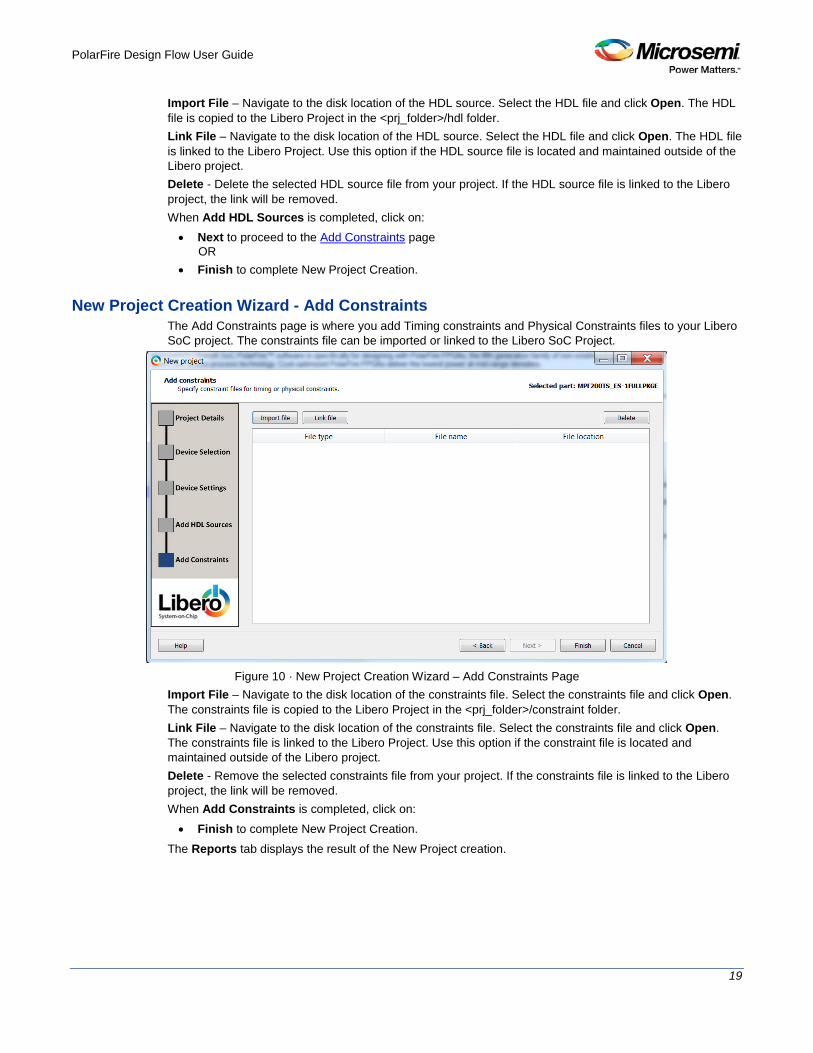
New Project Creation Wizard - Add Constraints The Add Constraints page is where you add Timing constraints and Physical Constraints files to your Libero SoC project. The constraints file can be imported or linked to the Libero SoC Project.
Figure 10 · New Project Creation Wizard – Add Constraints Page
Import File – Navigate to the disk location of the constraints file. Select the constraints file and click Open. The constraints file is copied to the Libero Project in the <prj_folder>/constraint folder. Link File – Navigate to the disk location of the constraints file. Select the constraints file and click Open. The constraints file is linked to the Libero Project. Use this option if the constraint file is located and maintained outside of the Libero project. Delete - Remove the selected constraints file from your project. If the constraints file is linked to the Libero project, the link will be removed. When Add Constraints is completed, click on: • Finish to complete New Project Creation.
The Reports tab displays the result of the New Project creation.

PolarFire Design Flow User Guide
20
Figure 11 · Reports Tab

PolarFire Design Flow User Guide
21
Create and Verify Design
Create your design with any or all of the following design capture tools: • Create SmartDesign • Create HDL • Create SmartDesign Testbench (optional, for simulation only) • Create HDL Testbench (optional, for simulation only)
Create SmartDesign About SmartDesign
SmartDesign is a visual block-based design creation/entry tool for the instantiation, configuration and connection of Microsemi IPs, user-generated IPs, custom/glue-logic HDL modules. This tool provides a canvas for instantiating and stitching together design objects. The final result from SmartDesign is a design-rule-checked and automatically abstracted synthesis-ready HDL file. A generated SmartDesign can be the entire FPGA design or a component subsystem to be re-used in a larger design. The following design objects can be instantiated in the SmartDesign Canvas: • Microsemi IP Cores • User-generated or third-party IP Cores • HDL design files • HDL + design files • Basic macros • Other SmartDesign components (*.cxf files) generated from SmartDesign in the current Libero SoC
project or may be imported from other Libero SoC projects. • Re-usable design blocks (*.cxz files) published from Libero SoC
For more information see the SmartDesign User Guide.
Create New SmartDesign This SmartDesign component may be the top level of the design or it may be used as a lower level SmartDesign component (after successful generation) in another design.
1. From the File menu, choose New > SmartDesign or in the Design Flow window or double-click Create SmartDesign. The Create New SmartDesign dialog box opens.
Figure 12 · Create New SmartDesign Dialog Box
2. Enter a name and click OK. The component appears in the Design Hierarchy tab of the Design Explorer. NOTE: The component name you choose much be unique in your project
For more information see the SmartDesign User Guide.
PolarFire Design Flow User Guide
22
Generating a SmartDesign Component Before your SmartDesign component can be used by downstream processes, such as synthesis and simulation, you must generate it.
Click the Generate button to generate a SmartDesign component. This will generate a HDL file in the directory <libero_project>/components/<library>/<yourdesign>. Note: The generated HDL file will be deleted when your SmartDesign design is modified and saved to
ensure synchronization between your SmartDesign component and its generated HDL file. Generating a SmartDesign component may fail if there are any DRC errors. DRC errors must be corrected before you generate your SmartDesign design. If the ports of a sub-design have changed, then the parent SmartDesign component will be annotated with the icon in the Design Hierarchy tab of the Design Explorer.
Generate Recursively vs. Non-Recursively These options are set in the Project Preference Dialog Box - Design Flow Preferences section. • In the "Recursive generation" mode, the Generate button will attempt to generate all sub-design
SmartDesigns, depth first. The parent SmartDesign will only be generated if all the sub-designs are generated successfully.
• In the "Non-Recursive generation" mode, the Generate button will only attempt to generate the specified SmartDesign. The generation can be marked as successful even if a sub-design is un-generated (either never attempted or unsuccessful). An un-generated component will be annotated with the icon in the Design Hierarchy tab of the Design Explorer.
Create Core from HDL You can instantiate any HDL module and connect it to other blocks inside SmartDesign. However, there are situations where you may want to extend your HDL module with more information before using it inside SmartDesign. • If you have an HDL module that contains configurable parameters or generics. • If your HDL module is intended to connect to a processor subsystem and has implemented the
appropriate bus protocol, then you can add a bus interface to your HDL module so that it can easily connect to the bus inside of SmartDesign.
To create a core from your HDL: 1. Import or create a new HDL source file; the HDL file appears in the Design Hierarchy. 2. Select the HDL file in the Design Hierarchy and click the HDL+ icon or right-click the HDL file and
choose Create Core from HDL. The Edit Core Definition – Ports and Parameters dialog appears. It shows you which ports and parameters were extracted from your HDL module.
3. Remove parameters that are not intended to be configurable by selecting them from the list and clicking the X icon. Remove parameters that are used for internal variables, such as state machine enumerations. If you removed a parameter by accident, click Re-extract ports and parameters from HDL file to reset the list so it matches your HDL module.

PolarFire Design Flow User Guide
23
Figure 13 · Edit Core Definition - Ports and Parameters Dialog Box
4. (Optional) Click Add/Edit Bus Interfaces to add bus interfaces to your core. After you have specified the information, your HDL turns into an HDL+ icon in the Design Hierarchy. Click and drag your HDL+ module from the Design Hierarchy to the Canvas. If you added bus interfaces to your HDL+ core, then it will show up in your SmartDesign with a bus interface pin that can be used to easily connect to the appropriate bus IP core. If your HDL+ has configurable parameters then double-clicking the object on the Canvas (or right-click and select Configure) invokes a configuration dialog that enables you to set these values. On generation, the specific configuration values per instance are written out to the SmartDesign netlist.
Figure 14 · HDL+ Instance and Configuration Dialog Box
You can right-click the instance and choose Modify HDL to open the HDL file inside the text editor.
Edit Core Definition You can edit your core definition after you created it by selecting your HDL+ module in the design hierarchy and clicking the HDL+ icon.

PolarFire Design Flow User Guide
24
Remove Core Definition You may decide that you do not want or need the extended information on your HDL module. You can convert it back to a regular HDL module. To do so, right-click the HDL+ in the Design Hierarchy and choose Remove Core Definition. After removing your definition, your instances in your SmartDesign that were referencing this core must be updated. Right-click the instance and choose Replace Component for Instance.
Designing with HDL Create HDL
Create HDL opens the HDL editor with a new VHDL or Verilog file. Your new HDL file is saved to your /hdl directory; all modules created in the file appear in the Design Hierarchy. You can use VHDL and Verilog to implement your design.
To create an HDL file: 1. In the Design Flow window, double-click Create HDL. The Create new HDL file dialog box opens. 2. Select your HDL Type. Choose whether or not to Initialize file with standard template to populate
your file with default headers and footers. The HDL Editor workspace opens. 3. Enter a Name. Do not enter a file extension; Libero SoC adds one for you. The filename must follow
Verilog or VHDL file naming conventions. 4. Click OK.
After creating your HDL file, click the Save button to save your file to the project.
Using the HDL Editor The HDL Editor is a text editor designed for editing HDL source files. In addition to regular editing features, the editor provides keyword highlighting, line numbering and a syntax checker. You can have multiple files open at one time in the HDL Editor workspace. Click the tabs to move between files. Editing Right-click inside the HDL Editor to open the Edit menu items. Available editing functions include cut, copy, paste, Go to line, Comment/Uncomment Selection and Check HDL File. These features are also available in the toolbar. Saving You must save your file to add it to your Libero SoC project. Select Save in the File menu, or click the Save icon in the toolbar. Printing Print is available from the File menu and the toolbar. Note: To avoid conflicts between changes made in your HDL files, Microsemi recommends that you use
one editor for all of your HDL edits.
HDL Syntax Checker
To run the syntax checker: In the Files list, double-click the HDL file to open it. Right-click in the body of the HDL editor and choose Check HDL File. The syntax checker parses the selected HDL file and looks for typographical mistakes and syntactical errors. Warning and error messages for the HDL file appear in the Libero SoC Log Window.

PolarFire Design Flow User Guide
25
Commenting Text
You can comment text as you type in the HDL Editor, or you can comment out blocks of text by selecting a group of text and applying the Comment command.
To comment or uncomment out text: 1. Type your text. 2. Select the text. 3. Right-click inside the editor and choose Comment Selection or Uncomment Selection.
Find
In the File menu, choose Find and the Find dialog box appears below the Log/Message window. You can search for a whole word or part of a word, with or without matching the case. You can search for: • Match Case • Match whole word • Regular Expression
The Find to Replace function is also supported.
Column Editing
Column Editing is supported. Press ALT+click to select a column of text to edit.
Importing HDL Source Files To import an HDL source file:
1. In the Design Flow window, right-click Create HDL and choose Import Files. The Import Files window appears.
2. Navigate to the drive/folder that contains the HDL file. 3. Select the file to import and click Open.
Note: SystemVerilog (*.sv), Verilog (*.v) and VHDL (*.vhd/*.vhdl) files can be imported.
Mixed-HDL Support in Libero SoC You must have ModelSim ME Pro to use mixed HDL in the Libero SoC. You must also have Synplify Pro to synthesize a mixed-HDL design. When you create a project, you must select a preferred language. The HDL files generated in the flow (such as the post-layout netlist for simulation) are created in the preferred language. The language used for simulation is the same language as the last compiled testbench. (For example, if tb_top is in Verilog, <fam>.v is compiled.) If your preferred language is Verilog, the post-synthesis and post-layout netlists are in Verilog 2001.
Designing with Block Flow For information about designing with Block Flow, see Designing with Blocks for Libero SoC Enhanced Constraint Flow.
SmartDesign Testbench SmartDesign Testbench is a GUI-based tool that enables you to design your testbench hierarchy. Use SmartDesign Testbench to instantiate and connect stimulus cores or modules to drive your design.

PolarFire Design Flow User Guide
26
You can create a SmartDesign Testbench by right-clicking a SmartDesign component in the Design Hierarchy and choosing Create Testbench > SmartDesign. SmartDesign Testbench automatically instantiates the selected SmartDesign component into the Canvas. You can also double-click Create SmartDesign Testbench in the Design Flow window to add a new SmartDesign testbench to your project. New testbench files appear in the Stimulus Hierarchy. SmartDesign Testbench automatically instantiates your SmartDesign component into the Canvas. You can instantiate your own stimulus HDL or simulation models into the SmartDesign Testbench Canvas and connect them to your DUT (design under test). You can also instantiate Simulation Cores from the Catalog. Simulation cores are simulation models (such as DDR memory simulation models) or basic cores that are useful for stimulus generation (such as Clock Generator, Pulse Generator, or Reset Generator). Click the Simulation Mode checkbox in the Catalog to view available simulation cores. Refer to the SmartDesign User Guide for more information.
HDL Testbench You can create a HDL Testbench by right-clicking a SmartDesign in the Design Hierarchy and choosing Create Testbench > HDL. HDL Testbench automatically instantiates the selected SmartDesign into the Component. You can also double-click Create HDL Testbench to open the Create New HDL Testbench dialog box. The dialog box enables you to create a new testbench file and gives you the option to include standard testbench content and your design data.
HDL Type Set your HDL Type: Verilog or VHDL for the testbench.
Name Specify a testbench file name. A *.v or a *.vhd file is created and opened in the HDL Editor.
Clock Period (ns) Enter a clock period in nanoseconds (ns) for the clock to drive the simulation. The default value is 100 ns (10 MHz). Libero creates in the testbench a SYSCLK signal with the specified frequency to drive the simulation. Set as Active Stimulus sets the HDL Testbench as the stimulus file to use for simulations. The active stimulus file/testbench is included in the run.do file that Libero generates to drive the simulation. Setting one testbench as the Active Stimulus is necessary when there are multiple testbenches in the stimulus hierarchy. Initialize with Standard Template adds boilerplate for a minimal standard test module. This test module does not include an instantiation of the root module under test. Instantiate Root Design Creates a test module that includes an instance of the root module under test, and clocking logic in the test module which drives the base clock of the root module under test.

PolarFire Design Flow User Guide
27
Figure 15 · Create New HDL Testbench File Dialog Box
Figure 16 · HDL Testbench Example - VHDL, Standard Template and Root Design Enabled
Verify Pre-Synthesized Design - RTL Simulation To perform pre-synthesis simulation, double-click Simulate under Verify Pre-Synthesized Design in the Design Flow window. Alternatively, in the Stimulus Hierarchy right-click the testbench and choose Simulate Pre-Synth Design > Run.
PolarFire Design Flow User Guide
28
If you want to perform pre-layout simulation with the post-synthesized netlist, in the Design Flow window, under Verify Post-Synthesized Implementation, double-click Generate Simulation File and then double-click Simulate. The default tool for RTL simulation in Libero SoC PolarFire is ModelSim™ ME Pro. ModelSim ME works with all levels of Libero SoC license (Eval, Silver, Gold and Platinum) whereas ModelSim Pro ME works with all levels of Libero SoC license except Silver. ModelSim ME and ModelSim ME Pro are custom editions of ModelSim PE that are integrated into Libero SoC's design environment. ModelSim for Microsemi is an OEM edition of Mentor Graphics ModelSim tools. ModelSim ME Pro supports mixed VHDL, Verilog, and SystemVerilog simulation but ModelSim ME does not. Both ModelSim editions only work with Microsemi simulation libraries and they are supported by Microsemi. Other editions of ModelSim are supported by Libero SoC. To use other editions of ModelSim, do not install ModelSim ME from the Libero SoC media. Note: ModelSim for Microsemi includes online help and documentation. After starting ModelSim, click the
Help menu. See the following topics for more information on simulation in Libero SoC: • Simulation Options • Selecting a Stimulus File for Simulation • Selecting additional modules for simulation • Performing Functional Simulation
Simulation Options You can set a variety of simulation options for your project.
To set your simulation options: 1. From the Project menu, choose Project Settings. 2. Click the simulation option you wish to edit: DO file, Waveforms, or Vsim commands. 3. Click Close to save your settings.
DO File
• Use automatic Do file - Select to execute the wave.do or other specified Do file. Use the wave.do file to customize the ModelSim Waveform window display settings.
• Simulation Run Time - Specify how long the simulation should run in nanoseconds. If the value is 0, or if the field is empty, there will not be a run command included in the run.do file.
• Testbench module name - Specify the name of your testbench entity name. Default is “testbench,” the value used by WaveFormer Pro.
• Top Level instance name - Default is <top_0>, the value used by WaveFormer Pro. The Libero SoC replaces <top> with the actual top level macro when you run ModelSim.
• Generate VCD file - Select this checkbox to have ModelSim automatically generate a VCD file based on the current simulation. VCD files can be used in SmartPower. For best results, Microsemi recommends that a postlayout simulation be used to generate the VCD.
• VCD filename - Specify the name of the VCD file that will be automatically generated by ModelSim • User defined DO file - Available if you opt not to use the automatic DO file. Input the path or browse
to your user-defined DO file. • DO Command parameters - Text in this field is added to the DO command.
Waveforms
• Include DO file - Including a DO file enables you to customize the set of signal waveforms that will be displayed in ModelSim.

PolarFire Design Flow User Guide
29
• Display waveforms for - You can display signal waveforms for either the top-level testbench or for the design under test. If you select top-level testbench then Libero SoC outputs the line 'add wave /testbench/*' in the DO file run.do. If you select DUT then Libero SoC outputs the line 'add wave /testbench/*' in the run.do file.
• Log all signals in the design - Saves and logs all signals during simulation.
Vsim Commands
• SDF timing delays - Select Minimum, Typical, or Maximum timing delays in the back-annotated SDF file.
• Resolution: The default is 1 ps. Some custom simulation resolutions may not work with your simulation library. Consult your simulation help for more information on how to work with your simulation library and detect infinite zero-delay loops caused by high resolution values.
• Additional options: Text entered in this field is added to the vsim command.
Simulation Libraries
• Verilog (or VHDL) library path - Enables you to choose the default library for your device, or to specify your own library. Enter the full pathname of your own library to use it for simulation.
• Restore Defaults: Restores factory settings.
Selecting a Stimulus File for Simulation Before running simulation, you must associate a testbench. If you attempt to run simulation without an associated testbench, the Libero SoC Project Manager asks you to associate a testbench or open ModelSim without a testbench.
To associate a stimulus: 1. Run simulation or in the Design Flow window under Verify Pre-Synthesized Design right-click
Simulate and choose Organize Input Files > Organize Stimulus Files. The Organize Stimulus Files dialog box appears.
2. Associate your testbench(es): In the Organize Stimulus Files dialog box, all the stimulus files in the current project appear in the Source Files in the Project list box. Files already associated with the block appear in the Associated Source Files list box. In most cases you will only have one testbench associated with your block. However, if you want simultaneous association of multiple testbench files for one simulation session, as in the case of PCI cores, add multiple files to the Associated Source Files list. To add a testbench: Select the testbench you want to associate with the block in the Source Files in the Project list box and click Add to add it to the Associated Source Files list. To remove a testbench: To remove or change the file(s) in the Associated Source Files list box, select the file(s) and click Remove. To order testbenches: Use the up and down arrows to define the order you want the testbenches compiled. The top level-entity should be at the bottom of the list.
3. When you are satisfied with the Associated Source Files list, click OK.
Selecting Additional Modules for Simulation Libero SoC passes all the source files related to the top-level module to simulation. If you need additional modules in simulation, in the Design Flow window right-click Simulate and choose Organize Input Files > Organize Source Files. The Organize Files for Simulation dialog box appears. Select the HDL modules you wish to add from the Simulation Files in the Project list and click Add to add them to the Associated Stimulus Files list
PolarFire Design Flow User Guide
30
Performing Functional Simulation To perform functional simulation:
1. Create your testbench. 2. Right-click Simulate (in the Design Flow window, Implement Design > Verify Post-Synthesis
Implementation > Simulate) and choose Organize Input Files > Organize Simulation Files from the right-click menu. In the Organize Files for Source dialog box, all the stimulus files in the current project appear in the Source Files in the Project list box. Files already associated with the block appear in the Associated Source Files list box. In most cases you will only have one testbench associated with your block. However, if you want simultaneous association of multiple testbench files for one simulation session, as in the case of PCI cores, add multiple files to the Associated Source Files list. To add a testbench: Select the testbench you want to associate with the block in the Source Files in the Project list box and click Add to add it to the Associated Source Files list. To remove a testbench: To remove or change the file(s) in the Associated Source Files list box, select the file(s) and click Remove.
3. When you are satisfied with the Associated Simulation Files list, click OK. 4. To start ModelSim ME Pro, right-click Simulate in the Design Hierarchy window and choose Open
Interactively. ModelSim starts and compiles the appropriate source files. When the compilation completes, the simulator runs for 1 s and the Wave window opens to display the simulation results.
5. Scroll in the Wave window to verify that the logic of your design functions as intended. Use the zoom buttons to zoom in and out as necessary.
6. From the File menu, select Quit.

PolarFire Design Flow User Guide
31
Libero SoC Constraint Management
In the FPGA design world, constraint files are as important as design source files. Constraint files are used throughout the FPGA design process to guide FPGA tools to achieve the timing and power requirements of the design. For the synthesis step, SDC timing constraints set the performance goals whereas non-timing FDC constraints guide the synthesis tool for optimization. For the Place-and-Route step, SDC timing constraints guide the tool to achieve the timing requirements whereas Physical Design Constraints (PDC) guide the tool for optimized placement and routing (Floorplanning). For Static Timing Analysis, SDC timing constraints set the timing requirements and design-specific timing exceptions for static timing analysis. Libero SoC provides the Constraint Manager as the cockpit to manage your design constraint needs. This is a single centralized graphical interface for you to create, import, link, check, delete, edit design constraints and associate the constraint files to design tools in the Libero SoC environment. The Constraint Manager allows you to manage constraints for SynplifyPro synthesis, Libero SoC Place-and- Route and the SmartTime Timing Analysis throughout the design process.
Invocation of Constraint Manager From the Design Flow Window After project creation, double-click Manage Constraints in the Design Flow window to open the Constraint Manager.
Figure 17 · Constraint Manager
Libero SoC Design Flow The Constraint Manager is Libero SoC’s single centralized Graphical User Interface for managing constraints files in the design flow.

PolarFire Design Flow User Guide
32
Figure 18 · Constraint Manager in Libero SoC Design Flow
Introduction to Constraint Manager Synthesis Constraints
The Constraint Manager manages these synthesis constraints and passes them to SynplifyPro: • Synplify Netlist Constraint File (*.fdc) • Compile Netlist Constraint File (*.ndc) • SDC Timing Constraints (*.sdc) • Derived Timing Constraints (*.sdc)

PolarFire Design Flow User Guide
33
Synplify Netlist Constraints (*.fdc)
These are non-timing constraints that help SynplifyPro optimize the netlist. From the Constraint Manager Netlist Attribute tab import (Netlist Attributes > Import) an existing FDC file or create a new FDC file in the Text Editor (Netlist Attributes > New > Create New Synplify Netlist Constraint). After the FDC file is created or imported, click the checkbox under synthesis to associate the FDC file with Synthesis.
Compile Netlist Constraints (*.ndc)
These are non-timing constraints that help Libero SoC optimize the netlist by combining I/Os with registers. I/Os are combined with a register to achieve better clock-to-out or input-to-clock timing. From the Constraint Manager Netlist Attribute tab import (Netlist Attributes > Import) an existing NDC file or create a new NDC file in the Text Editor (Netlist Attributes > New > Create New Compile Netlist Constraint). After the NDC file is created or imported, click the checkbox under synthesis to associate the NDC file with Synthesis.
SDC Timing Constraints (*.sdc)
These are timing constraints to guide SynplifyPro to optimize the netlist to meet the timing requirements of the design. From the Constraint Manager Timing tab, import (Timing > Import) or create in the Text Editor (Timing > New) a new SDC file. After the SDC file is created or imported, click the checkbox under synthesis to associate the SDC file with Synthesis. After the synthesis step, you may click Edit with Constraint Editor > Edit Synthesis Constraints to edit existing constraints or add new SDC constraints.
Derived Timing Constraints (*.sdc)
These are timing constraints LiberoSoC generates for IP cores used in your design. These IP cores, available in the Catalog, are family/device-dependent. Once they are configured, generated and instantiated in the design, the Constraint Manager can generate SDC timing constraints based on the configuration of the IP core and the component SDC. From the Constraint Manager Timing tab, click Derive Constraints to generate the Derived Timing Constraints (*.sdc). Click the *derived_constraints.sdc file to associate it with synthesis.
Place and Route Constraints The Constraint Manager manages these constraints for the Place-and-Route step: • I/O PDC Constraints (*io.pdc) • Floorplanning PDC Constraints (*fp.pdc) • Timing SDC constraint file (*.sdc)
I/O PDC Constraints
These are I/O Physical Design Constraints in an *io.pdc file. From the Constraint Manager I/O Attribute tab, you may import (I/O Attributes > Import) or create in the Text Editor (I/O Attributes > New) an *io.pdc file. Click the checkbox under Place and Route to associate the file with Place and Route.
Floorplanning PDC Constraints
These are floorplanning Physical Design Constraints in a *fp.pdc file. From the Constraint Manager Floor Planner tab, you may import (Floor Planner > Import) or create in the Text Editor (Floor Planner > New) a *fp.pdc file. Click the checkbox under Place and Route to associate the file with Place and Route.

PolarFire Design Flow User Guide
34
Timing SDC Constraint file (*.sdc)
These are timing constraint SDC files for Timing-driven Place and Route. From the Constraint Manager Timing tab, you may import (Timing > Import) or create in the Text Editor (Timing > New) a timing SDC file. Click the checkbox under Place and Route to associate the SDC file with Place and Route. This file is passed to Timing-driven Place and Route (Place and Route > Configure Options > Timing Driven).
Timing Verifications Constraints The Constraint Manager manages the SDC timing constraints for Libero SoC’s SmartTime, which is a Timing Verifications/Static Timing analysis tool. SDC timing constraints provide the timing requirements (e.g. create_clock and create_generated_clock) and design-specific timing exceptions (e.g. set_false_path and set_multicycle_path) for Timing Analysis. From the Constraint Manager Timing tab, you may import (Timing > Import) or create in the Text Editor (Timing > New) a SDC timing file. Click the checkbox under Timing Verifications to associate the SDC timing constraints file with Timing Verifications. Note: You may have the same set of SDC Timing Constraints for Synthesis, Place and Route and Timing Verifications to start with in the first iteration of the design process. However, very often and particularly when the design is not meeting timing requirements you may find it useful in subsequent iterations to have different sets of Timing SDC files associated with different tools. Take for example; you may want to change/modify the set of SDC timing constrains for Synthesis or Place and Route to guide the tool to focus on a few critical paths. The set of SDC timing constraints associated with Timing Verifications can remain unchanged. The Constraint Manager lets you associate/dis-associate the constraint files with the different tools with a mouse click.
Constraint Manager Components The Constraint Manager has four tabs, each corresponding to a constraint type that Libero SoC supports: • I/O Attributes • Timing • Floor Planner • Netlist Attribute
Clicking the tabs displays the constraint file of that type managed in the Libero SoC project.
Constraint File and Tool Association Each constraint file can be associated/dis-associated with a design tool by checking and unchecking the checkbox corresponding to the tool and the constraint file. When associated with a tool, the constraint file is passed to the tool for processing.
Figure 19 · Constraint File and Tool Association
Note: Libero SoC’s Design Flow window displays the state the tool is in. A green check mark indicates
successful completion. A warning icon indicates invalidation of the state because the input files for the tool have changed since the last successful run. Association of a new constraint file with a tool or dis-association of an existing constraint file with a tool invalidates the state of the tool with which the constraint file is associated.

PolarFire Design Flow User Guide
35
All Constraint files except Netlist Attributes can be opened, read and edited by Interactive Tools invoked from the Constraint Manager directly. The Interactive Tools are: • I/O Editor • Chip Planner • Constraint Editor
Constraint Type Constraint File
Extension
Location inside Project Associated with Design Tool
Interactive Tool (For Editing)
I/O Attributes PDC (*.pdc) <proj>\constraints\io\*.pdc Place and Route I/O Editor
Floorplanning PDC (*.pdc) <proj>\constraints\fp\*.pdc Place and Route Chip Planner
Timing SDC (*.sdc) <proj>\constraints\*.sdc Synthesis, Place and Route, Timing Verification
Constraint Editor
Netlist Attributes FDC (*.fdc) <proj>\constraints\*.fdc Synthesis n/a
NDC (*.ndc) <proj>\constraints\*.ndc Synthesis n/a
Derive Constraints in Timing Tab The Constraint Manager can generate timing constraints for IP cores used in your design. These IP cores, available in the Catalog, are family/device-dependent. Once they are configured, generated and instantiated in your design, the Constraint Manager can generate SDC timing constraints based on the configuration of the IP core and the component SDC. A typical example of an IP core for which the Constraint Manager can generate SDC timing constraints is the IP core for Clock Conditioning Circuitry (CCC).
Create New Constraints From the Constraint Manager, create new constraints in one of two ways: • Use the Text Editor • Use Libero SoC’s Interactive Tools
To create new constraints from the Constraint Manager using the Text Editor: 1. Select the Tab that corresponds to the type of constraint you want to create. 2. Click New. 3. When prompted, enter a file name to store the new constraint. 4. Enter the constraint in the Text Editor. 5. Click OK.
The Constraint file is saved and visible in the Constraint Manager in the tab you select: • I/O Attributes constraint file (<proj>\io\*.pdc) in the I/O Attributes tab • Floorplanning constraints (<proj>\fp\*.pdc) in the Floor Planner tab • Timing constraints (<proj>\constraints\*.sdc) in the Timing tab
6. (Optional) Double-click the constraint file in the Constraint Manager to open and add more constraints to the file.
To create new constraints from the Constraint Manager using Interactive Tools: Note: Netlist Attribute constraints cannot be created by an Interactive Tool. Netlist Attribute files can only be created with a Text Editor. Note: Except for timing constraints for Synthesis, the design needs to be in the post-synthesis state to enable editing/creation of new constraints by the Interactive Tool.

PolarFire Design Flow User Guide
36
Note: The *.pdc or *.sdc file the Constraint Manager creates is marked [Target]. This denotes that it is the target file. A target file receives and stores new constraints from the Interactive Tool. When you have multiple constraint files of the same type, you may select any one of them as target. When there are multiple constraint files but none of them is set as target, or there are zero constraint files, Libero SoC creates a new file and set it as target to receive and store the new constraints created by the Interactive Tools.
1. Select the Tab that corresponds to the type of constraint you want to create. 2. Click Edit to open the Interactive Tools. The Interactive Tool that Libero SoC opens varies with the
constraint type: • I/O Editor to edit/create I/O Attribute Constraints. See PolarFire I/O Editor User Guide for details. • Chip Planner to edit/create Floorplanning constraints. See PolarFire Chip Planner User Guide for
details. • Constraint Editor to edit/create Timing Constraints. See Timing Constraints Editor User Guide for
details. 3. Create the Constraints in the Interactive Tool. Click Commit and Save. 4. Check that Libero SoC creates these file to store the new constraints:
• Constraints\io\user.pdc file when I/O constraints are added and saved in I/O Editor. • Constraints\fp\user.pdc file when floorplanning constraints are added and saved in Chip Planner. • Constraints\user.sdc file when Timing Constraints are added and saved in Constraint Editor
Constraint File Order When there are multiple constraint files of the same type associated with the same tool, use the Up and Down arrow to arrange the order the constraint files are passed to the associated tool. Constraint file order is important when there is a dependency between constraints files. When a floorplanning PDC file assigns a macro to a region, the region must first be created and defined. If the PDC command for region creation and macro assignment are in different PDC files, the order of the two PDC files is critical.
1. To move a constraint file up, select the file and click the Up arrow. 2. To move a constraint file down, select the file and click the Down arrow.
Figure 20 · Move constraint file Up or Down
Note: Changing the order of the constraint files associated with the same tool invalidates the state of that tool.
Import a Constraint File Use the Constraint Manager to import a constraint file into the Libero SoC project. When a constraint file is imported, a local copy of the constraint file is created in the Libero Project.
To import a constraint file: 1. Click the Tab corresponding to the type of constraint file you want to import. 2. Click Import. 3. Navigate to the location of the constraint file. 4. Select the constraint file and click Open. A copy of the file is created and appears in Constraint
Manager in the tab you have selected.

PolarFire Design Flow User Guide
37
Link a Constraint File Use the Constraint Manager to link a constraint file into the Libero SoC project. When a constraint file is linked, a file link rather than a copy is created from the Libero project to a constraint file physically located and maintained outside the Libero SoC project.
To link a constraint file: 1. Click the Tab corresponding to the type of constraint file you want to link. 2. Click Link. 3. Navigate to the location of the constraint file you want to link to. 4. Select the constraint file and click Open. A link of the file is created and appears in Constraint
Manager under the tab you have selected. The full path location of the file (outside the Libero SoC project) is displayed.
Check a Constraint File Use the Constraint Manager to check a constraint file.
To check a constraint file: 1. Select the tab for the constraint type to check. 2. Click Check.
Note: I/O constraints, Floorplanning constraints, Timing constraints, and Netlist Attributes can be checked only when the design is in the proper state. A pop-up message appears when the check is made and the design state is not proper for checking.
All constraint files associated with the tool are checked. Files not associated with a tool are not checked. For Timing Constraints, select from the Check drop-down menu one of the following: • Check Synthesis Constraints • Check Place and Route Constraints • Check Timing Verification Constraints
Figure 21 · Check Constraints
Check Synthesis Constraints checks only the constraint files associated with the Synthesis. Check Place and Route Constraints checks only the constraint files associated with Place and Route Check Timing Verification Constraints checks only the Constraint Files associated with Timing Verification. For the constraint files and tool association shown in the SDC file and Tool Association Figure below: • Check Synthesis Constraints checks the following files:

PolarFire Design Flow User Guide
38
• top_derived_constraints.sdc • user.sdc • mytiming2.sdc
• Check Place and Route Constraints checks the following files: • top_derived_constraints.sdc • mytiming.sdc • mytiming2.sdc
• Check Timing Verification Constraints checks the following files: • top_derived_constraints.sdc • user.sdc • mytiming.sdc • mytiming2.sdc
Note: sdfsadf.sdc Constraint File is not checked because it is not associated with any tool.
Figure 22 · Timing Constraints SDC file and Tool Association
When a constraint file is checked, the Constraint Manager: • Checks the SDC or PDC syntax. • Compares the design objects (pins, cells, nets, ports) in the constraint file versus the design objects in
the netlist (RTL or post-layout ADL netlist). Any discrepancy (e.g. constraints on a design object which does not exist in the netlist) are flagged as errors and reported in the *.log file or message window.
Check Result
If the check is successful, this message pops up.
Figure 23 · Check Successful Message
If the check fails, this error message pops up.
Figure 24 · Check Fails Message

PolarFire Design Flow User Guide
39
Constraint Type Check for Tools Required Design State
Before Checks
Netlist Used for Checks
Check Result Details
I/O Constraints Place and Route Post-Synthesis ADL Netlist Libero Message Window
Floorplanning Constraints Place and Route Post-Synthesis ADL Netlist Libero Message Window
Timing Constraints Synthesis Pre-Synthesis RTL Netlist synthesis_sdc_check.log
Place and Route Post-Synthesis ADL Netlist placer_sdc_check.log
Timing Verifications Post-Synthesis ADL Netlist timing_sdc_check.log
Netlist Attributes (*.fdc) Synthesis Pre-Synthesis RTL Netlist *cck.srr file
Netlist Attributes (*.ndc) Synthesis Pre-Synthesis RTL Netlist Libero Log Window
Edit a Constraint File The Edit button in the Constraint Manager allows you to: • Create new constraint files. See To create new constraints from the Constraint Manager using the Text
Editor for details. • Edit existing constraint files.
To edit a constraint file Note: Netlist Attributes cannot be edited by an Interactive Tool. Use the Text Editor to edit the Netlist Attribute constraint (*.fdc and *.ndc) files.
1. Select the tab for the constraint type to edit. An Interactive Tool is opened to make the edits. 2. Click Edit.
• All constraint files associated with the tool are edited. Files not associated with the tool are not edited.
• When a constraint file is edited, the constraints in the file are read into the Interactive Tool. • Different Interactive Tools are used to edit different constraints/different files:
1. I/O Editor to edit I/O Attributes (<proj>\io\*.pdc). For details, refer to the PolarFire I/O Editor User Guide.
2. Chip Planner to edit Floorplanning Constraints (<proj>\fp\*.pdc). For details, refer to the Chip Planner User's Guide (Chip Planner > Help > Reference Manuals)
3. Constraint Editor to edit Timing Constraints (constraints\*.sdc). For details, refer to the Timing Constraints Editor User’s Guide (Help > Constraints Editor User’s Guide)
Note: I/O constraints, Floorplanning constraints, Timing constraints can be edited only when the design is in the proper state. A message pops up if the file is edited when the design state is not proper for edits. If, for example, you open the Constraints Editor (Constraint Manager > Edit) to edit timing constraints when the design state is not post-synthesis, a pop-up message appears.
Figure 25 · Pop-up Message

PolarFire Design Flow User Guide
40
3. For Timing Constraints, click one of the following to edit from the Edit with Constraint Editor drop-down menu. • Edit Synthesis Constraints • Edit Place and Route Constraints • Edit Timing Verification Constraints
Figure 26 · Edit Drop-down Menu
For the constraint files and tool association shown in the Timing Constraint File and Tool Association below: • Edit Synthesis Constraints reads the following files into the Constraint Editor:
• user.sdc • myuser1.sdc
• Edit Place and Route Constraints reads the following files into the Constraint Editor: • user.sdc • mytiming2.sdc • myuser1.sdc
• Edit Timing Verification Constraints reads the following files into the Constraint Editor: • user.sdc • mytiming2.sdc
Figure 27 · Timing Constraint File and Tool Association
4. Edit the constraint in the Interactive Tool, save and exit. 5. The edited constraint is written back to the original constraint file when the tool exits.
Refer to the Timing Constraints Editor User’s Guide (Help > Constraints Editor User’s Guide) for details on how to enter/modify timing constraints. Note: When a constraint file is edited inside an Interactive Tool, the Constraint Manager is disabled until the Interactive Tool is closed. Note: Making changes to a constraint file invalidates the state of the tool with which the constraint file is associated. For instance, if Place and Route has successfully completed with user.sdc as the associated

PolarFire Design Flow User Guide
41
constraint file, then making changes to user.sdc invalidates Place and Route. The green checkmark (denoting successful completion) next to Place and Route turns into a warning icon when the tool is invalidated.
See Also: PolarFire FPGA Design Constraints User Guide
Constraint Types Libero SoC manages four different types of constraints: • I/O Attributes Constraints – Used to constrain placed I/Os in the design. Examples include setting
I/O standards, I/O banks, and assignment to Package Pins, output drive, and so on. These constraints are used by Place and Route.
• Timing Constraints – Specific to the design set to meet the timing requirements of the design, such as clock constraints, timing exception constraints, and disabling certain timing arcs. These constraints are passed to Synthesis, Place and Route, and Timing Verification.
• Floor Planner Constraints – Non-timing floorplanning constraints created by the user or Chip Planner and passed to Place and Route to improve Quality of Routing.
• Netlist Attributes - Microsemi-specific attributes that direct the Synthesis tool to synthesize/optimize the, leveraging the architectural features of the Microsemi devices. Examples include setting the fanout limits, specifying the implementation of a RAM, and so on. These constraints are passed to the Synthesis tool only.
The following table below summarizes the features and specifics of each constraint type.
Constraint Type
File Location File Ext.
User Actions
Constraints Edited By Constraints Used By
Changes Invalidate
Design State?
I/O Attributes
<proj>/constraints/io folder
*.pdc Create New, Import, Link, Edit, Check
I/O Editor Or user editing the *.pdc file in Text Editor
Place and Route
YES
Timing Constraints
<proj>/constraints folder
*.sdc Create New, Import, Link, Edit, Check
Constraint Editor Or user editing the *.sdc file in Text Editor
Synplify Place and Route Verify Timing (SmartTime)
YES
Floor Planner Constraints
<proj>/constraints/fp folder
*.pdc Create New, Import, Link, Edit, Check
Chip Planner Or user Editing the *.pdc file in Text Editor
Place and Route
YES
Netlist Attributes
<proj>/constraints folder
*.fdc Create New, Import, Link, Check
User to Open in Text Editor to Edit
Synplify YES
Netlist Attributes
<proj>/constraints folder
*.ndc Import, Link, Check
User to Open in Text Editor to Edit
Synplify YES

PolarFire Design Flow User Guide
42
Constraint Manager – I/O Attributes Tab The I/O Attributes tab allows you to manage I/O attributes/constraints for your design’s Inputs, Outputs, and Inouts. All I/O constraint files (PDC) have the *.pdc file extension and are placed in the <Project_location>/constraint/io folder. Available actions are: • New – Creates a new I/O PDC file and saves it into the <Project_location>\constraint\io folder. There
are two options: • Create New I/O Constraint • Create New I/O Constraint From Root Module -- This will pre-populate the PDC file with
information from the Root Module Having selected the create method: • When prompted, enter the name of the constraint file. • The file is initially opened in the text editor for user entry.
• Import – Imports an existing I/O PDC file into the Libero SoC project. The I/O PDC file is copied into the <Project_location>\constraint\io folder.
• Link – Creates a link in the project’s constraint folder to an existing I/O PDC file (located and maintained outside of the Libero SoC project).
• Edit with I/O Editor – Opens the I/O Editor tool to modify the I/O PDC file(s) associated with the Place and Route tool.
• Check – Checks the legality of the PDC file(s) associated with the Place and Route tool against the gate level netlist.
When the I/O Editor tool is invoked or the constraint check is performed, all files associated files with the Place and Route tool are being passed for processing. When you save your edits in the I/O Editor tool, the I/O PDC files affected by the change will be updated to reflect the change you have made in the I/O Editor tool. New I/O constraints you add in the I/O Editor tool are written to the Target file (if a target file has been set) or written to a new PDC file (if no file is set as target) and stored in the <project>\constraint\io folder.
Figure 28 · Constraint Manager – I/O Attributes Tab
Right-click the I/O PDC files to access the available actions: • Set/UnSet as Target – Sets or clears the selected file as the target to store new constraints created in
the I/O Editor tool. Newly created constraints only go into the target constraint file. Only one file can be set as target.
• Open in Text Editor – Opens the selected constraint file in the Libero Text Editor.
PolarFire Design Flow User Guide
43
• Clone – Copies the file to a file with a different name. The original file name and its content remain intact.
• Rename – Renames the file to a different name. • Copy File Path - Copies the file path to the clipboard. • Delete From Project and Disk – Deletes the file from the project and from the disk. • Unlink: Copy file locally – Removes the link and copies the file into the <Project_location>\constraint
\io folder. This selection is available only for linked constraints files.
File and Tool Association Each I/O constraint file can be associated or disassociated with the Place and Route tool. Click the checkbox under Place and Route to associate/disassociate the file from the tool.
I/O Settings Reserve Pins for Device Migration – This option allows you to reserve pins in the currently selected device that are not bonded in a device or list of devices you may later decide to migrate your design to. Select the target device(s) you may migrate to later to ensure that there will be no device/package incompatibility if you migrate your design to that device. Reserve Pins for Probes – Check this box if you plan to use live probes when debugging your design with SmartDebug.
Constraint Manager – Timing Tab The Timing tab allows you to manage timing constraints throughout the design process. Timing constraints files (SDC) have the *.sdc file extension and are placed in the <Project_location>\constraint folder. Available actions are: • New – Creates a new timing SDC file and saves it into the <Project_location>\constraint folder.
• When prompted, enter the name of the constraint file. • The file is initially opened in the text editor for user entry.
• Import – Imports an existing timing SDC file into the Libero SoC project. The timing SDC file is copied into the <Project_location>\constraint folder.
• Link – Creates a link in the project’s constraint folder to an existing timing SDC file (located and maintained outside of the Libero SoC project).
• Edit with Constraint Editor – Opens the Timing Constraints Editor (see Timing Constraints Editor User Guide for details) to modify the SDC file(s) associated with one of the three tools: • Synthesis – When selected, the timing SDC file(s) associated with the Synthesis tool is loaded
in the constraints editor for editing. • Place and Route - When selected, the timing SDC file(s) associated with the Place and Route
tool is loaded in the constraints editor for editing. • Timing Verification - When selected, the timing SDC file(s) associated with the Timing
Verification tool is loaded in the constraints editor for editing. • Check – Check the legality of the SDC file(s) associated with one of the three tools described below:
• Synthesis – The check is performed against the pre-synthesis HDL design. • Place and Route – The check is performed against the post-synthesis gate level netlist. • Timing Verification – The check is performed against the post-synthesis gate level netlist.
• Derive Constraints – When clicked, Libero generates a timing SDC file based on user configuration of IP core, components and component SDC. It generates the create_clock and create_generated_clock SDC timing constraints. This file is named <top_level_> derived_constraints.sdc. The component SDC and the generated <root>_derived_constraint.sdc files are dependent on the IP cores and vary with the device family.
Examples:
create -name {REF_CLK_PAD_0} -period 5 [ get_ports { REF_CLK_PAD_0 } ]
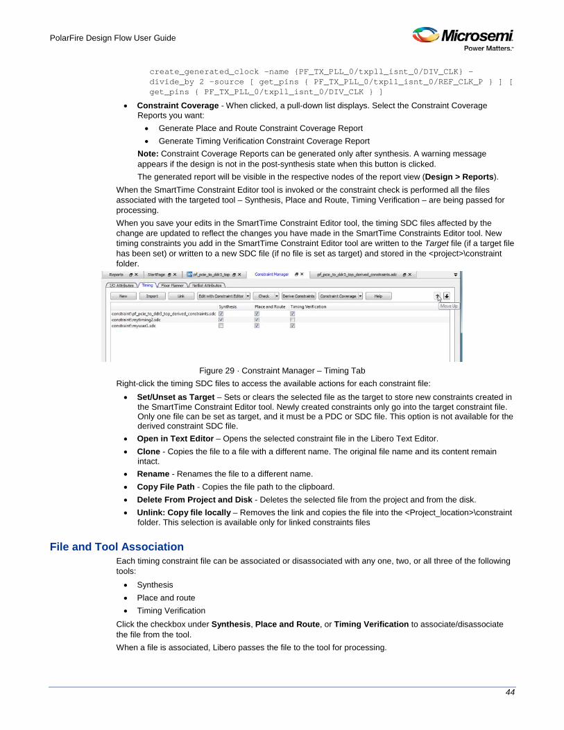
PolarFire Design Flow User Guide
44
create_generated_clock -name {PF_TX_PLL_0/txpll_isnt_0/DIV_CLK} -divide_by 2 -source [ get_pins { PF_TX_PLL_0/txpll_isnt_0/REF_CLK_P } ] [ get_pins { PF_TX_PLL_0/txpll_isnt_0/DIV_CLK } ]
• Constraint Coverage - When clicked, a pull-down list displays. Select the Constraint Coverage Reports you want: • Generate Place and Route Constraint Coverage Report • Generate Timing Verification Constraint Coverage Report
Note: Constraint Coverage Reports can be generated only after synthesis. A warning message appears if the design is not in the post-synthesis state when this button is clicked. The generated report will be visible in the respective nodes of the report view (Design > Reports).
When the SmartTime Constraint Editor tool is invoked or the constraint check is performed all the files associated with the targeted tool – Synthesis, Place and Route, Timing Verification – are being passed for processing. When you save your edits in the SmartTime Constraint Editor tool, the timing SDC files affected by the change are updated to reflect the changes you have made in the SmartTime Constraints Editor tool. New timing constraints you add in the SmartTime Constraint Editor tool are written to the Target file (if a target file has been set) or written to a new SDC file (if no file is set as target) and stored in the <project>\constraint folder.
Figure 29 · Constraint Manager – Timing Tab
Right-click the timing SDC files to access the available actions for each constraint file: • Set/Unset as Target – Sets or clears the selected file as the target to store new constraints created in
the SmartTime Constraint Editor tool. Newly created constraints only go into the target constraint file. Only one file can be set as target, and it must be a PDC or SDC file. This option is not available for the derived constraint SDC file.
• Open in Text Editor – Opens the selected constraint file in the Libero Text Editor. • Clone - Copies the file to a file with a different name. The original file name and its content remain
intact. • Rename - Renames the file to a different name. • Copy File Path - Copies the file path to the clipboard. • Delete From Project and Disk - Deletes the selected file from the project and from the disk. • Unlink: Copy file locally – Removes the link and copies the file into the <Project_location>\constraint
folder. This selection is available only for linked constraints files
File and Tool Association Each timing constraint file can be associated or disassociated with any one, two, or all three of the following tools: • Synthesis • Place and route • Timing Verification
Click the checkbox under Synthesis, Place and Route, or Timing Verification to associate/disassociate the file from the tool. When a file is associated, Libero passes the file to the tool for processing.

PolarFire Design Flow User Guide
45
Example
Figure 30 · File and Tool Association Example
In the context of the graphic above, when Edit Synthesis Constraint is selected, user.sdc, top_derived_constraints.sdc, and mytiming2.sdc are read (because these three files are associated with Synthesis); mytiming.sdc and sdfsadf.sdc are not read (because they are not associated with Synthesis). When the SmartTime Constraint Editor opens for edit, the constraints from all the files except for sdfsadf.sdc are read and loaded into the Constraint Editor. Any changes you made and saved in the Constraint Editor are written back to the files. Note: sdfsadf.sdc Constraint File is not checked because it is not associated with any tool.
Derived Constraints Libero SoC is capable of generating SDC timing constraints for design components when the root of the design has been defined. Click Derive Constraints in the Constraint Manager’s Timing tab to generate SDC timing constraints for your design’s components. The generated constraint file is named <root>_derived.sdc and is created by instantiating component SDC files created by IP configurators (e.g., CCC) and oscillators used in the design. The <root>_derived.sdc file is associated by default to the Synthesis, Place and Route and Timing Verification tool. You can change the file association in the Constraint Manager by checking or unchecking the checkbox under the tool.
To generate SDC timing constraints for IP cores: 1. Configure and generate the IP Core. 2. From the Constraint Manager’s Timing tab, click Derive Constraints (Constraint Manager > Timing >
Derive Constraints). The Constraint Manager generates the <root>_derived_constraints.sdc file and places it in the Timing Tab along with other user SDC constraint file.
3. When prompted for a Yes or No on whether or not you want the Constraint Manager to automatically associate the derived SDC file to Synthesis, Place and Route, and Timing Verification, click Yes to accept automatic association or No and then check or uncheck the appropriate checkbox for tool association. Note: Microsemi recommends the <root>_derived_constraints.sdc be always associated with all three tools: Synthesis, Place and Route, and Verify Timing. Before running SynplifyPro Synthesis, associate the <root>_derived_constraints.sdc file with Synthesis and Place and Route. This will ensure that the design objects (such as nets and cells) in the <root>_derived_constraints.sdc file are preserved during the synthesis step and the subsequent Place and Route step will not error out because of design object mismatches between the post-synthesis netlist and the <root>_derived_constraints.sdc file.
Note: Full hierarchical path names are used to identify design objects in the generated SDC file. Note: The Derive Constraints button is available for HDL-based and SmartDesign-based design flows. It is not available if the design flow is EDIF/EDN (Project > Project Settings > Design Flow > Enable Synthesis [not checked].

PolarFire Design Flow User Guide
46
Constraint Manager – Floor Planner Tab The Floor Planner tab allows you to manage floorplanning constraints. Floorplanning constraints files (PDC) have the *.pdc file extension and are placed in the <Project_location>\constraint\fp folder. Available actions are: • New – Creates a new floorplanning PDC file and saves it into the <Project_location>\constraint\fp
folder. • Import – Imports an existing floorplanning PDC file into the Libero SoC project. The floorplanning PDC
file is copied into the <Project_location>\constraint\fp folder. • Link – Creates a link in the project’s constraint folder to an existing floorplanning PDC file (located and
maintained outside of the Libero SoC project). • Edit with Chip Planner – Opens the Chip Planner tool to modify the floorplanning PDC file(s)
associated with the Place and Route tool. • Check – Checks the legality of the PDC file(s) associated with the Place and Route tool against the
gate level netlist. When the Chip Planner tool is invoked or the constraint check is performed, all files associated with the Place and Route tool are passed for processing. When you save your edits in the Chip Planner tool, the floorplanning PDC files affected by the change are updated to reflect the change you made in the Chip Planner tool. New floorplanning constraints that you add in the Chip Planner tool are written to the Target file (if a target file has been set) or written to a new PDC file (if no file is set as target) and stored in the <project>\constraint\fp folder.
Figure 31 · Constraint Manager – Floor Planner Tab
Right-click the floorplanning PDC files to access the available actions: • Set/Unset as Target – Sets or clears the selected file as the target to store new constraints created in
the Chip Planner tool. Newly created constraints only go into the target constraint file. Only one file can be set as target.
• Open in Text Editor – Opens the selected constraint file in the Libero Text Editor. • Clone - Copies the file to a file with a different name. The original file name and its content remain
intact. • Rename - Renames the file to a different name. • Copy File Path - Copies the file path to the clipboard. • Delete From Project and Disk - Deletes the selected file from the project and from the disk. • Unlink: Copy file locally – Removes the link and copies the file into the
<Project_location>\constraint\fp folder. The selection is available only for linked constraint files.

PolarFire Design Flow User Guide
47
File and Tool Association Each floorplanning constraint file can be associated or disassociated to the Place and Route tool. Click the checkbox under Place and Route to associate/disassociate the file from the tool. When a file is associated, Libero passes the file to the tool for processing.
See Also Chip Planner User Guide
Constraint Manager – Netlist Attributes Tab The Netlist Attributes tab allows you to manage netlist attribute constraints to optimize your design during the synthesis and/or compile process. Timing constraints should be entered using SDC files managed in the Timing tab. Netlist Attribute constraints files are placed in the <Project_location>\constraint folder. Libero SoC manages two types of netlist attributes: • FDC constraints are used to optimize the HDL design using Synopsys SynplifyPro synthesis engine
and have the *.fdc extension. • NDC constraints are used to optimize the post-synthesis netlist with the Libero SoC compile engine
and have the *.ndc file extension Available operations are: • New – Creates a new FDC or NDC netlist attribute constraints file in the <Project_location>\constraint
folder. • Import – Imports an existing FDC or NDC netlist attribute constraints file into the Libero SoC project.
The FDC or NDC netlist attribute constraints file is copied into the <Project_location>\constraint folder. • Link – Creates a link in the project’s constraint folder to an existing existing FDC or NDC netlist
attribute constraints file (located and maintained outside of the Libero SoC project). • Check – Checks the legality of the FDC and NDC file(s) associated with the Synthesis or Compile
tools. When the constraint check is performed, all files associated with the Synthesis or Compile tools are passed for processing.
Figure 32 · Constraint Manager – Netlist Attributes Tab
Right-click the FDC or NDC files to access the available actions: • Open in Text Editor – Opens the selected constraint file in the Libero SoC Text Editor.

PolarFire Design Flow User Guide
48
• Clone - Copies the file to a file with a different name. The original file name and its content remain intact.
• Rename - Renames the file to a different name. • Copy File Path - Copies the file path to the clipboard. • Delete From Project and Disk – Deletes the file from the project and from the disk. • Unlink: Copy file locally – Removes the link and copies the file into the <Project_location>\constraint
folder. This menu item is available only for linked constraint files.
File and Tool Association Each netlist attributes constraint file can be associated with or disassociated from the Synthesis tool. Click the checkbox under Synthesis (Compile) to associate/disassociate the file from Synthesis (Compile). When a file is associated, Libero passes the file to Synthesis (Compile) for processing when Synthesis is run. When Synthesis is ON (Project > Project Settings > Design Flow > Enable synthesis [checked]) for a project, the Design Flow Synthesis action runs both the synthesis engine and the post-synthesis compile engine. When Synthesis is OFF (Project > Project Settings > Design Flow > Enable synthesis [not checked]) for a project, the Design Flow Synthesis action is replaced by the Compile action and runs the compile engine on the gate-level netlist (EDIF or Verilog) available in the project.

PolarFire Design Flow User Guide
49
Implement Design
Synthesize Double-click Synthesize to run synthesis on your design with the default settings specified in the synthesis tool. If you want to run the synthesis tool interactively, right-click Synthesize and choose Open Interactively. If you open your tool interactively, you must complete synthesis from within the synthesis tool. The default synthesis tool included with Libero SoC is Synplify Pro ME. If you want to use a different synthesis tool, you can change the settings in your Tool Profiles. You can organize input synthesis source files via the Organize Source Files dialog box.
Synthesize Options Some families enable you to set or change synthesis configuration options for your synthesis tool. To do so, in the Design Flow window, expand Implement Design, right-click Synthesize and choose Configure Options. This opens the Synthesize Options dialog box.
Figure 33 · Synthesize Options Dialog Box

PolarFire Design Flow User Guide
50
HDL Synthesis Language Settings
HDL Synthesis language options are no longer specified in this dialog box. Please refer to Project Settings: Design Flow Options.
Global Nets (Promotions and Demotions)
Use the following options to specify to the Synthesis tool the threshold value beyond which the Synthesis tool promotes the pins to globals: • Minimum number of clock pins – Specifies the threshold value for Clock pin promotion. The default
value is 2. • Minimum number of asynchronous pins – Specifies the threshold value for Asynchronous pin
promotion. The default is 800 for PolarFire. • Minimum fanout of non-clock nets to be kept on globals – Specifies the threshold value for data
pin promotion to global resources. It is the minimum fanout of non-clock (data) nets to be kept on globals (no demotion). The default is 5000 (must be between 1000 and 200000).
• Number of global resources – This can be used to control number of Global resources you want to use in your design. By default this displays the number of available global resources for the die you have selected for the project and varies with different die sizes. For PolarFire, the default is 24 for all dies.
• Maximum number of global nets that could be demoted to row-globals – Specifies the maximum number of global nets that could be demoted to row-globals. The default is 16 (must be between 0 to 50).
• Minimum fanout of global nets that could be demoted to row-globals – Specifies the minimum fanout of global nets that could be demoted to row-global. It is undesirable to have high fanout nets demoted using row globals because it may result in high skew. The default is 300. (Must be between 25 to 5000). If you run out of global routing resources for your design, reduce this number (to allow more globals to be demoted to Row Globals) or select a bigger die for your design.
Note: Hardwired connections to global resources, such as CCC hardwired connections to GB , IO Hardwired connections to GB, and so on, cannot be controlled by these options.
Optimizations
Enable retiming – Check this box to enable Retiming during synthesis. Retiming is the process of automatically moving registers (register balancing) across combinational gates to improve timing, while ensuring identical logic behavior. The default is no retiming during synthesis. RAM optimized for: Use this option to guide the Synthesis tool to optimize RAMs to achieve your design goal. • High speed – RAM Optimization is geared towards Speed. The resulting synthesized design achieves
better performance (higher speed) at the expense of more FPGA resources. • Low power – RAM Optimization is geared towards Low Power. RAMs are inferred and configured to
ensure the lowest power consumption. Map seq-shift register components to: Use this option to select the mapping of sequential logic: • Registers – When selected, sequential shift logic in the RTL is mapped to registers. • RAM64x12 – When selected, sequential shift logic in the RTL is mapped to a 64x12 RAM block. This
is the default setting.

PolarFire Design Flow User Guide
51
Additional options for Synplify Pro synthesis
Script File
Click the Browse button to navigate to a Synplify Tcl file that contains the Synplify Pro-specific options. Libero passes the options in the Tcl file to Synplify Pro for processing. Additional Options Use this field to enter additional Synplify options. Put each additional option on a separate line. Note: Libero passes these additional options “as-is” to Synplify Pro for processing; no syntax checks are performed. All of these options are set on the Active Implementation only. The list of recommended Synthesis Tcl options below can be added or modified in the Tcl Script File or Additional Options Editor. Note: The options from the Additional Options Editor will always have priority over the Tcl Script file options if they are same. set_option -use_fsm_explorer 0/1
set_option -frequency 200.000000
set_option -write_verilog 0/1
set_option -write_vhdl 0/1
set_option -resolve_multiple_driver 1/0
set_option -rw_check_on_ram 0/1
set_option -auto_constrain_io 0/1
set_option -run_prop_extract 1/0
set_option -default_enum_encoding default/onehot/sequential/gray
set_option -maxfan 30000
set_option -report_path 5000
set_option -update_models_cp 0/1
set_option -preserve_registers 1/0
set_option -continue_on_error 1/0
set_option -symbolic_fsm_compiler 1/0
set_option -compiler_compatible 0/1
set_option -resource_sharing 1/0
set_option -write_apr_constraint 1/0
set_option -dup 1/0
set_option -enable64bit 1/0
set_option -fanout_limit 50
set_option -frequency auto
set_option -hdl_define SLE_INIT=2
set_option -hdl_param -set "width=8"
set_option -looplimit 3000
set_option -fanout_guide 50
set_option -maxfan_hard 1/0
set_option -num_critical_paths 10
set_option -safe_case 0/1
Any additional options can be entered through the Script File or Additional Options Editor. All of these options can be added and modified outside of Libero through interactive SynplifyPro. Refer to the Synplify Pro Reference Manual for detailed information about the options and supported families. The following options are already set by Libero. Do not include them in the additional options field or Script File: add_file <*>
impl <*>
project_folder <*>
PolarFire Design Flow User Guide
52
add_folder <*>
constraint_file <*>
project <*>
project_file <*>
open_file <*>
set_option –part
set_option -package
set_option -speed_grade
set_option -top_module
set_option -technology
set_option -opcond
set_option -vlog_std
set_option -vhdl2008
set_option -disable_io_insertion
set_option -async_globalthreshold
set_option -clock_globalthreshold
set_option -globalthreshold
set_option -low_power_ram_decomp
set_option -retiming
Synplify Pro ME Synplify Pro ME is the default synthesis tool for Libero SoC. To run synthesis using Synplify Pro ME and default settings, right-click Synthesize and choose Run. If you wish to use custom settings you must run synthesis interactively.
To run synthesis using Synplify Pro ME with custom settings: 1. If you have set Synplify as your default synthesis tool, right-click Synthesize in the Libero SoC Design
Flow window and choose Open Interactively. Synplify starts and loads the appropriate design files, with a few pre-set default values.
2. From Synplify’s Project menu, choose Implementation Options. 3. Set your specifications and click OK. 4. Deactivate synthesis of the defparam statement. The defparam statement is only for simulation tools
and is not intended for synthesis. Embed the defparam statement in between translate_on and translate_off synthesis directives as follows : /* synthesis translate_off */ defparam M0.MEMORYFILE = "meminit.dat" /*synthesis translate_on */ // rest of the code for synthesis
5. Click the RUN button. Synplify compiles and synthesizes the design into an EDIF, *.edn, file. Your EDIF netlist is then automatically translated by the software into an HDL netlist. The resulting *edn and *.vhd files are visible in the Files list, under Synthesis Files. Should any errors appear after you click the Run button, you can edit the file using the Synplify editor. Double-click the file name in the Synplify window showing the loaded design files. Any changes you make are saved to your original design file in your project.
6. From the File menu, choose Exit to close Synplify. A dialog box asks you if you would like to save any settings that you have made while in Synplify. Click Yes.
Note: See the Microsemi Attribute and Directive Summary in the Synplify online help for a list of attributes related to Microsemi devices.
Note: To add a clock constraint in Synplify you must add "n:<net_name>" in your SDC file. If you put the net_name only, it does not work.

PolarFire Design Flow User Guide
53
Compile Netlist The Compile Netlist step appears in the Design Flow window only when the design source is EDIF (EDIF design flow). To enable the EDIF design flow, turn off the Enable Synthesis option in the Project > Project Settings > Design Flow page. Note: When the design source is HDL/SmartDesign, this Compile Netlist step is not available in the Design Flow window. Instead, it is automatically run as part of the Synthesis step.
Options The Compile Netlist Options sets the threshold value for global resource promotion and demotion when Place and Route is executed.
Figure 34 · Compile Netlist Options Dialog Box
Number of global resources - The number of available global resources for the die is reported in this field. The number varies with the die size you select for the Libero SoC project. The following options allow you to set the maximum/minimum values for promotion and demotion of global routing resources. Maximum Number of global nets that could be demoted to row-globals – Specifies the maximum number of global nets that can be demoted to row-globals. The default is 16. Minimum fanout of global nets that could be demoted to row-globals – Specifies the minimum fanout of global nets that can be demoted to row-global. The default is 1000. If you run out of global routing resources for your design, reduce this number (to allow more globals to be demoted) or select a larger die for your design. Minimum fanout of non-clock nets to be kept on globals – Specifies the minimum fanout of non-clock (data) nets to be kept on globals (no demotion). The default is 5000 (valid range is 1000 to 200000). If you run out of global routing resources for your design, increase this number or select a larger die for your design.

PolarFire Design Flow User Guide
54
Resource Usage After layout, you can check the resource usage of your design. From the Design menu, choose Reports (Design > Reports). Click <design_name>_layout_log.log to open the log file. The log file contains a Resource Usage report, which lists the type and percentage of resource used for each resource type relative to the total resources available for the chip.
Type Used Total Percentage
4LUT 400 86184 0.46
DFF 300 86184 0.34
I/O Register 0 795 0.00
Logic Element 473 86184 0.55
4LUTs are 4-input Look-up Tables that can implement any combinational logic functions with up to four inputs. The Logic Element is a logic unit in the fabric. It may contain a 4LUT, a DFF, or both. The number of Logic Elements in the report includes all Logic Elements, regardless of whether they contain 4LUT only, DFF only, or both.
Overlapping of Resource Reporting The number of 4LUTs in the report are the total number used for your design, regardless of whether or not they are combined with the DFFs. Similarly, the number of DFFs in the report are the total number used for your design, regardless of whether or not they are combined with 4LUT’s. In the report above, there is a total of 473 Logic Elements (LEs) used for the design. 300 of the 473 LEs have DFFs inside, which means 173 (473-300) of them have no DFFs in them. These 173 LEs are using only the 4LUTs portion of the LE. 400 of the 473 LEs have 4LUTs inside, which means 73 (473-400) of them have no 4LUTS in them. These 73 LEs are using only the DFF portion of the LE.
LEs using DFF Only = 473-400 = 73
LEs using 4LUTS only = 473-300= 173
= 246 (Total of LEs using 4LUTS ONLY or DFF ONLY)
Report’s Overlapped resource = 227 (LEs using both 4LUTS and DFF)
Total number of LEs used = 473
The area where the two circles overlap represents the overlapped resources in the Resource Usage report.

PolarFire Design Flow User Guide
55
Constraint Flow in Implementation Design State Invalidation
The Libero SoC Design Flow window displays status icons to indicate the status of the design state. For any status other than a successful run, the status icon is identified with a tooltip to give you additional information.
Status Icon
Tooltip Description Possible Causes/Remedy
N/A Tool has not run yet.
NEW state Tool has not run or it has been cleaned.
Tool runs successfully.
Tool runs with no errors. PASS state.
N/A
Varies with the tool.
Tool runs but with Warnings.
Varies with the tool (e.g., for the Compile Netlist step, not all I/Os have been assigned and locked).
Tool Fails. Tool fails to run. Invalid command options or switches, invalid design
objects, invalid design constraints.
Design State is Out of Date.
Tool state changes from PASS to OUT OF DATE.
Since the last successful run, design source design files, constraint files or constraint file/tool association, constraint files order, tool options, and/or project settings have changed.
Timing Constraints have not been met.
Timing Verification runs successfully but the design fails to meet timing requirements.
Design fails Timing Analysis. Design has either set-up or hold time violations or both. See PolarFire FPGA Timing Constraints User Guide on how to resolve the timing violations.
Constraints and Design Invalidation
A tool in the Design Flow changes from a PASS state (green check mark) to an OUT OF DATE state when a source file or setting affecting the outcome of that tool has changed.
The out-of-date design state is identified by the icon in the Design Flow window. Sources and/or settings are defined as: • HDL sources (for Synthesis), gate level netlist (for Compile), and Smart Design components • Constraint files associated with a tool • Upstream tools in the Design Flow:
• If the tool state of a Design Flow tool changes from PASS to OUT OF DATE, the tool states of all the tools below it in the Design Flow, if already run and are in PASS state, also change to OUT OF DATE with appropriate tooltips. For example, if the Synthesis tool state changes from PASS to OUT OF DATE, the tool states of Place and Route tool as well as all the tools below it in the Design Flow change to OUT OF DATE.
• If a Design Flow tool is CLEANED, the tool states of all the tools below it in the Design Flow, if already run, change from PASS to OUT OF DATE.
• If a Design Flow tool is rerun, the tool states of all the tools below it in the Design Flow, if already run, are CLEANED.
• Tool Options

PolarFire Design Flow User Guide
56
• If the configuration options of a Design Flow tool (right-click the tool and choose Configure Options) are modified, the tool states of that tool and all the other tools below it in the Design Flow, if already run, are changed to OUT OF DATE with appropriate tooltips.
• Project Settings: • Device selection • Device settings • Design Flow • Analysis operating conditions
Setting Changed Note Design Flow Tools Affected New State of the Affected Design Flow
Tools
Die Part# is changed
All CLEANED/NEW
Package Part# is changed
All CLEANED/NEW
Speed Part# is changed
All CLEANED/NEW
Core Voltage Part# is changed
All CLEANED/NEW
Range Part# is changed
All CLEANED/NEW
Default I/O Technology Synthesize, and all tools below it OUT OF DATE
Reserve Pins for Probes Place and Route, and all tools below it OUT OF DATE
PLL Supply Voltage (V) Verify Power, Generate FPGA Array Data and all other “Program and Debug Design” tools below it
OUT OF DATE
Power On Reset Delay Generate FPGA Array Data and all other “Program and Debug Design” tools below it
OUT OF DATE
System controller suspended mode
Generate FPGA Array Data and all other “Program and Debug Design” tools below it
OUT OF DATE
Preferred Language None N/A
Enable synthesis All OUT OF DATE
Synthesis gate level netlist format
Synthesize CLEANED/NEW
Reports(Maximum number of high fanout nets to be displayed)
None N/A
Abort flow if errors are found in PDC
None N/A

PolarFire Design Flow User Guide
57
Setting Changed Note Design Flow Tools Affected New State of the Affected Design Flow
Tools
Abort flow if errors are found in SDC
None N/A
Temperature range(C) Verify Timing, Post Layout Simulate, and Verify Power
OUT OF DATE
Core voltage range(V) Verify Timing, Post Layout Simulate, and Verify Power
OUT OF DATE
Default I/O voltage range Verify Timing, Post Layout Simulate, and Verify Power
OUT OF DATE
• Note: Cleaning a tool means the output files from that tool are deleted including log and report files, and
the tool’s state is changed to NEW.
Check Constraints When a constraint file is checked, the Constraint Checker does the following: • Checks the syntax • Compares the design objects (pins, cells, nets, ports) in the constraint file versus the design objects in
the netlist (RTL or post-layout ADL netlist). Any discrepancy (e.g., constraints on a design object which does not exist in the netlist) are flagged as errors and reported in the *_sdc.log file
Design State and Constraints Check
Constraints can be checked only when the design is in the right state.
Constraint Type Check for Tools Required Design State Before Checking
Netlist Used for Design Objects Checks
Check Result
I/O Constraints Place and Route Post-Synthesis ADL Netlist Reported in Libero Log Window
Floorplanning Constraints
Place and Route Post-Synthesis ADL Netlist par_sdc.log
Timing Constraints Synthesis Pre-Synthesis RTL Netlist synthesis_sdc.log
Place and Route Post-Synthesis ADL Netlist par_sdc.log
Timing Verification Post-Synthesis ADL Netlist vt_sdc.log
Netlist Attributes FDC Check Pre-Synthesis RTL Netlist Libero Message Window
Netlist Attributes NDC Check Pre-Synthesis RTL Netlist Reported in Libero Log Window
A pop-up message appears when the check is made and the design flow has not reached the right state,

PolarFire Design Flow User Guide
58
Figure 35 · Pop-Up message: Design State insufficient for Constraints Check operation
Edit Constraints Click the Edit with I/O Editor/Chip Planner/Constraint Editor button to edit existing and add new constraints. Except for the Netlist Attribute constraints (*.fdc and *.ndc) file, which cannot be edited by an interactive tool, all other constraint types can be edited with an Interactive Tool. The *.fdc and *.ndc files can be edited using the Libero SoC Text Editor. The I/O Editor is the interactive tool to edit I/O Attributes, Chip Planner is the interactive tool to edit Floorplanning Constraints, and the Constraint Editor is the interactive tool to edit Timing Constraints. For Timing Constraints that can be associated to Synthesis, Place and Route, and Timing Verification, you need to specify which group of constraint files you want the Constraint Editor to read and edit: • Edit Synthesis Constraints - reads associated Synthesis constraints to edit. • Edit Place and Route Constraints - reads only the Place and Route associated constraints. • Edit Timing Verification Constraints - reads only the Timing Verification associated constraints.
For the three SDC constraints files (a.sdc, b.sdc, and c.sdc, each with Tool Association as shown in the table below) when the Constraint Editor opens, it reads the SDC file based on your selection and the constraint file/tool association.
Synthesis Place and Route Timing Verification
a.sdc X X
b.sdc X X
c.sdc [target] X X X
• Edit Synthesis Constraints reads only the b.sdc and c.sdc when Constraint Editor opens. • Edit Place and Route Constraints reads a.sdc, b.sdc and c.sdc when Constraint Editor opens. • Edit Timing Verification Constraints reads a.sdc and c.sdc when Constraint Editor opens.
Constraints in the SDC constraint file that are read by the Constraint Editor and subsequently modified by you will be written back to the SDC file when you save the edits and close the Constraint Editor. When you add a new SDC constraint in the Constraint Editor, the new constraint is added to the c.sdc file, because it is set as target. If no file is set as target, Libero SoC creates a new SDC file to store the new constraint.
Constraint Type and Interactive Tool
Constraint Type Interactive Tool For Editing
Design Tool the Constraints File is Associated
Required Design State Before Interactive Tool Opens for Edit
I/O Constraints I/O Editor Place and Route Tool Post-Synthesis
Floorplanning Constraints
Chip Planner Place and Route Tool Post-Synthesis

PolarFire Design Flow User Guide
59
Constraint Type Interactive Tool For Editing
Design Tool the Constraints File is Associated
Required Design State Before Interactive Tool Opens for Edit
Timing Constraints
SmartTime Constraints Editor
Synthesis Tool Place and Route Timing Verification
Pre-Synthesis Post-Synthesis Post-Synthesis
Netlist Attributes Synplify Netlist Constraint (*.fdc)
Interactive Tool Not Available Open the Text Editor to edit.
Synthesis Pre-Synthesis
Netlist Attributes Compile Netlist Constraint (*.ndc)
Interactive Tool Not Available Open the Text Editor to edit.
Synthesis Pre-Synthesis
Note: If the design is not in the proper state when Edit with <Interactive tool> is invoked, a pop-up message appears.
Note: When an interactive tool is opened for editing, the Constraint Manager is disabled. Close the Interactive Tool to return to the Constraint Manager.
Place and Route Double-click Place and Route to run Place and Route on your design with the default settings.
Place and Route Options To change your Place and Route settings from the Design Flow window, expand Implement Design, right-click Place and Route and choose Configure Options. This opens the Layout Options dialog box.

PolarFire Design Flow User Guide
60
Figure 36 · Layout Options Dialog Box

PolarFire Design Flow User Guide
61
Figure 37 · Layout Options Dialog Box - with Block Flow enabled
Timing-Driven
Timing-Driven Place and Route is selected by default. The primary goal of timing-driven Place and Route is to meet timing constraints, specified by you or generated automatically. Timing-driven Place and Route typically delivers better performance than Standard Place and Route. If you do not select Timing-driven Place and Route, timing constraints are not considered by the software, although a delay report based on delay constraints entered in SmartTime can still be generated for the design.
Power-Driven
Select this option to run Power-Driven layout. The primary goal of power-driven layout is to reduce dynamic power while still maintaining timing constraints.

PolarFire Design Flow User Guide
62
Driver Replication
Enables an algorithm to replicate critical net drivers to reduce timing violations. The algorithm prints the list of registers along with the duplicate names. Each set of names should be used in place of the original register in any specified timing constraint.
High Effort Layout
Enable this option to optimize performance; layout runtime will increase if you select this option.
Repair Minimum Delay Violations
Enable this option to instruct the Router engine to repair Minimum Delay violations for Timing-Driven Place and Route mode (Timing-Driven Place and Route option enabled). The Repair Minimum Delay Violations option, when enabled, performs an additional route that attempts to repair paths that have minimum delay and hold time violations. This is done by increasing the length of routing paths and inserting routing buffers to add delay to the top 100 violating paths. When this option is enabled, Libero adjusts the programmable delays through I/Os to meet hold time requirements from input to registers. For register-to-register paths, Libero adds buffers. Libero iteratively analyzes paths with negative minimum delay slacks (hold time violations) and chooses suitable connections and locations to insert buffers. Not all paths can be repaired using this technique, but many common cases will benefit. Even when this option is enabled, Libero will not repair a connection or path which: • Is a hardwired, preserved, or global net • Has a sink pin which is a clock pin • Is violating a maximum delay constraint (that is, the maximum delay slack for the pin is negative) • May cause the maximum delay requirement for the sink pin to be violated (setup violations) • Has the sink and driver pins located in the same cluster
Typically, this option is enabled in conjunction with the Incremental Layout option when a design’s maximum delay requirements have been satisfied. Every effort is made to avoid creating max-delay timing violations on worst case paths. Min Delay Repair produces a report in the implementation directory which lists all of the paths that were considered. If your design continues to have internal hold time violations, you may wish to rerun repair Minimum Delay Violations (in conjunction with Incremental Layout). This will analyze additional paths if you originally had more than 100 violating paths.
Incremental Layout
Choose Incremental Layout to use previous placement data as the initial placement for the next run. If a high number of nets fail, relax constraints, remove tight placement constraints, deactivate timing-driven mode, or select a bigger device and rerun Place and Route. You can preserve portions of your design by employing Compile Points, which are RTL partitions of the design that you define before synthesis. The synthesis tool treats each Compile Point as a block which enables you to preserve its structure and timing characteristics. By executing Layout in Incremental Mode, locations of previously-placed cells and the routing of previously-routed nets is preserved. Compile Points make it easy for you to mark portions of a design as black boxes, and let you divide the design effort between designers or teams. See the Synopsys FPGA Synthesis Pro ME User Guide for more information.

PolarFire Design Flow User Guide
63
Use Multiple Pass
Check Multiple Pass to run multiple pass of Place and Route to get the best Layout result. Click Configure to specify the criteria you want to use to determine the best layout result.
Block Creation – Number of row-global resources
This option is available only when the Block Creation option is turned on (Project > Project Settings > Design Flow > Enable Block Creation). The value entered here restricts the number of row-global resources available in every half-row of the device. During Place and Route of the block, the tool will not exceed this capacity on any half-row. The default value is the maximum number of row-globals. If you enter a value lower than the maximum capacity (the default), the layout of the block will be able to integrate with the rest of the design if they consume the remaining row-global capacity.
See Also Mutiple Pass Layout Configuration extended_run_lib
Multiple Pass Layout Configuration Multiple Pass Layout attempts to improve layout quality by selecting from a greater number of Layout results. This is done by running individual place and route multiple times with varying placement seeds and measuring the best results with specified criteria. • Before running Multiple Pass Layout, save your design. • Multiple Pass Layout is supported by all families. • Multiple Pass Layout saves your design file with the pass that has the best layout results. If you want
to preserve your existing design state, you should save your design file with a different name before proceeding. To do this, from the File menu, choose Save As.
• Four types of reports (timing, maximum delay timing violations, minimum delay timing violations, and power) for each pass are written to the working directory to assist you in later analysis: • <root_module_name>_timing_r<runNum>_s<seedIndex>.rpt • <root_module_name>_timing_violations_r<runNum>_s<seedIndex>.rpt • <root_module_name>_timing_violations_min_r<runNum>_s<seedIndex>.rpt • <root_module_name>_power_r<runNum>_s<seedIndex>.rpt • <root_module_name>_iteration_summary.rpt provides additional details about the saved files.
To configure your multiple pass options: 1. When running Layout, select Use Multiple Passes in the Layout Options dialog box. 2. Click Configure. The Multi-Pass Configuration dialog box appears.

PolarFire Design Flow User Guide
64
Figure 38 · Multi-Pass Configuration Dialog Box
3. Set the options and click OK. Number of passes: Set the number of passes (iterations) using the slider. 1 is the minimum and 25 is the maximum. The default is 5. Start at seed index: Set the specific index into the array of random seeds which is to be the starting point for the passes. If not specified, the default behavior is to continue from the last seed index that was used. Measurement: Select the measurement criteria you want to compare layout results against. • Slowest clock: Select to use the slowest clock frequency in the design in a given pass as the
performance reference for the layout pass. • Specific clock: Select to use a specific clock frequency as the performance reference for all layout
passes. Timing violations: This is the default. Select Timing Violations to use the pass that best meets the slack or timing-violations constraints. Note: You must enter your own timing constraints through SmartTime or SDC. • Maximum delay: Select to examine timing violations (slacks) obtained from maximum delay analysis.
This is the default. • Minimum delay: Select to examine timing violations (slacks) obtained from minimum delay analysis. • Select by: Worst Slack or Total Negative Slack to specify the slack criteria.
• When Worst Slack (default) is selected, the largest amount of negative slack (or least amount of positive slack if all constraints are met) for each pass is identified, and the largest value of all passes determines the best pass.

PolarFire Design Flow User Guide
65
• When Total Negative Slack is selected, the sum of negative slacks from the first 100 paths in the Timing Violations report for each pass is identified, and the largest value of all the passes determines the best pass. If no negative slacks exist for a pass, the worst slack is used to evaluate that pass.
• Stop on first pass without violations: Select to stop performing remaining passes if all timing constraints have been met (when there are no negative slacks reported in the timing violations report).
• Total power: Select to determine the best pass to be the one that has the lowest total power (static + dynamic) of all layout passes.
Iteration Summary Report The file <root_module>_iteration_summary.rpt records a summary of how the multiple pass run was invoked either through the GUI or extended_run_lib Tcl script, with arguments for repeating each run. Each new run appears with its own header in the Iteration Summary Report with fields RUN_NUMBER and INVOKED AS, followed by a table containing Seed Index, corresponding Seed value, Comparison data, Report Analyzed, and Saved Design information.
Figure 39 · Iteration Summary Report
See Also Place and Route extended_run_lib
Verify Post Layout Implementation Verify Timing
Verify Timing Configuration
Use this dialog box to configure the ‘Verify Timing’ tool to generate a timing constraint coverage report and detailed static timing analysis and violation reports based on different combinations of process speed, operating voltage, and temperature. For the timing and timing violation reports you can select: • Max Delay Static Timing Analysis report based on Slow process, Low Voltage, and High Temperature
operating conditions. • Min Delay Static Timing Analysis report based on Fast process, High Voltage, and Low Temperature
operating conditions. • Max Delay Static Timing Analysis report based on Fast process, High Voltage, and Low Temperature
operating conditions.
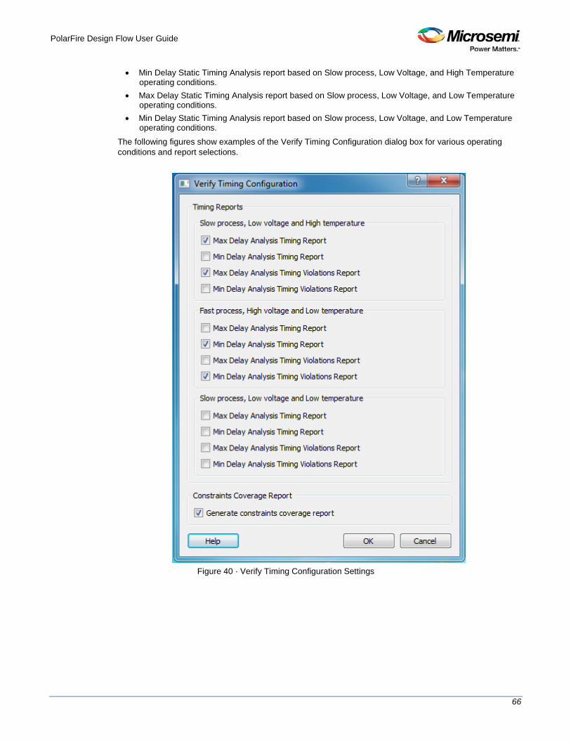
PolarFire Design Flow User Guide
66
• Min Delay Static Timing Analysis report based on Slow process, Low Voltage, and High Temperature operating conditions.
• Max Delay Static Timing Analysis report based on Slow process, Low Voltage, and Low Temperature operating conditions.
• Min Delay Static Timing Analysis report based on Slow process, Low Voltage, and Low Temperature operating conditions.
The following figures show examples of the Verify Timing Configuration dialog box for various operating conditions and report selections.
Figure 40 · Verify Timing Configuration Settings

PolarFire Design Flow User Guide
67
Types of Timing Reports
From the Design Flow window > Verify Timing, you can generate the following types of reports: Timing reports – These reports display timing information organized by clock domain. Four types of timing reports are available. You can configure which reports to generate using the ‘Verify Timing’ configuration dialog box (Design Flow > Verify Timing > Configure Options). The following reports can be generated: • Max Delay Static Timing Analysis report based on Slow process, Low Voltage, and High Temperature
operating conditions. • Min Delay Static Timing Analysis report based on Fast process, High Voltage, and Low Temperature
operating conditions. • Max Delay Static Timing Analysis report based on Fast process, High Voltage, and Low Temperature
operating conditions. • Min Delay Static Timing Analysis report based on Slow process, Low Voltage, and High Temperature
operating conditions. • Max Delay Static Timing Analysis report based on Slow process, Low Voltage, and Low Temperature
operating conditions. • Min Delay Static Timing Analysis report based on Slow process, Low Voltage, and Low Temperature
operating conditions. Timing violations reports – These reports display timing information organized by clock domain. Four types of timing violations reports are available. You can configure which reports to generate using the ‘Verify Timing’ configuration dialog (Design Flow > Verify Timing > Configure Options). The following reports can be generated: • Max Delay Analysis Timing Violation report based on Slow process, Low Voltage, and High
Temperature operating conditions. • Min Delay Analysis Timing Violation report eport based on Fast process, High Voltage, and Low
Temperature operating conditions. • Max Delay Analysis Timing Violation report based on Fast process, High Voltage, and Low
Temperature operating conditions. • Min Delay Analysis Timing Violation report based on Slow process, Low Voltage, and High
Temperature operating conditions. • Max Delay Analysis Timing Violation report based on Slow process, Low Voltage, and Low
Temperature operating conditions. • Min Delay Analysis Timing Violation report based on Slow process, Low Voltage, and Low
Temperature operating conditions.

PolarFire Design Flow User Guide
68
Constraints coverage report – This report displays the overall coverage of the timing constraints set on the current design. <root>_timing_constraints_coverage.xml (generated by default)
Report Listing Icon Legend
Icon Definition
Timing requirement met for this report
Timing requirement not met (violations) for this report
Timing report available for generation but has not been selected/configured for generation
Figure 41 · Reports Example
SmartTime SmartTime is the Libero SoC gate-level static timing analysis tool. With SmartTime, you can perform complete timing analysis of your design to ensure that you meet all timing constraints and that your design operates at the desired speed with the right amount of margin across all operating conditions. Note: See the Timing Constraints Editor for help with creating and editing timing constraints.
Static Timing Analysis (STA) Static timing analysis (STA) offers an efficient technique for identifying timing violations in your design and ensuring that it meets all your timing requirements. You can communicate timing requirements and timing exceptions to the system by setting timing constraints. A static timing analysis tool will then check and report setup and hold violations as well as violations on specific path requirements. STA is particularly well suited for traditional synchronous designs. The main advantage of STA is that unlike dynamic simulation, it does not require input vectors. It covers all possible paths in the design and does all the above with relatively low run-time requirements. The major disadvantage of STA is that the STA tools do not automatically detect false paths in their algorithms as it reports all possible paths, including false paths, in the design. False paths are timing paths in the design that do not propagate a signal. To get a true and useful timing analysis, you need to identify those false paths, if any, as false path constraints to the STA tool and exclude them from timing considerations.

PolarFire Design Flow User Guide
69
Timing Constraints SmartTime supports a range of timing constraints to provide useful analysis and efficient timing-driven layout.
Timing Analysis SmartTime provides a selection of analysis types that enable you to: • Find the minimum clock period/highest frequency that does not result in a timing violations • Identify paths with timing violations • Analyze delays of paths that have no timing constraints • Perform inter-clock domain timing verification • Perform maximum and minimum delay analysis for setup and hold checks
To improve the accuracy of the results, SmartTime evaluates clock skew during timing analysis by individually computing clock insertion delays for each register. SmartTime checks the timing requirements for violations while evaluating timing exceptions (such as multicycle or false paths).
SmartTime and Place and Route Timing constraints impact analysis and place and route the same way. As a result, adding and editing your timing constraints in SmartTime is the best way to achieve optimum performance.
SmartTime and Timing Reports From SmartTime > Tools > Reports, the following report files can be generated: • Timing Report (for both Max and Min Delay Analysis) • Timing Violations Report (for both Max and Min Delay Analysis) • Bottleneck Report • Constraints Coverage Report • Combinational Loop Report
SmartTime and Cross-Probing into Chip Planner From SmartTime, you can select a design object and cross-probe the same design object in Chip Planner. Design objects that can be cross-probed from SmartTime to Chip Planner include: • Ports • Macros • Timing Paths
Refer to the SmartTime User’s Guide for details (Libero SoC > Help > Reference Manual > SmartTime User’s Guide).
SmartTime and Cross-Probing into Constraint Editor From SmartTime, you can cross-probe into the Constraint Editor. Select a Timing Path in SmartTime’s Analysis View and add a Timing Exception Constraint (False Path, Multicycle Path, Max Delay, Min Delay) . The Constraint Editor reflects the newly added timing exception constraint. Refer to the SmartTime Static Timing Analyzer User Guide for details.
Verify Power Right-click on the Verify Power command in the Design Flow window to see the following menu of options:

PolarFire Design Flow User Guide
70
Figure 42 · Verify Power right-click menu
Verify Power sub-commands
Run - Runs the default power analysis and produces a power report. This is also the behavior of a double-click to Verify Power. Clean and Run All - Identical to the sequence of commands "Clean" (see below) and "Run" Open interactively - Brings up the SmartPower for Libero SoC tool (see below) Clean - Clears the history of any previous default power analysis, including deletion of any reports. The flow
task completion icon will also be cleared. Configure Options ... - This sub-command is only available if there are options to configure, in which case a dialog box will pop-up presenting the user with technology-specific choices. View Report - This sub-command is only available and visible if a report is available. When View Report is invoked, the Report tab will be added to the Libero SoC GUI window, and the Power Report will be selected and made visible.
SmartPower
SmartPower is the Microsemi SoC state-of-the-art power analysis tool. SmartPower enables you to globally and in-depth visualize power consumption and potential power consumption problems within your design, so you can make adjustments – when possible – to reduce power. SmartPower provides a detailed and accurate way to analyze designs for Microsemi SoC FPGAs: from top-level summaries to deep down specific functions within the design, such as gates, nets, IOs, memories, clock domains, blocks, and power supply rails. You can analyze the hierarchy of block instances and specific instances within a hierarchy, and each can be broken down in different ways to show the respective power consumption of the component pieces. SmartPower also analyses power by functional modes, such as Active, Flash*Freeze, Shutdown, Sleep, or Static, depending on the specific FPGA family used. You can also create custom modes that may have been created in the design. Custom modes can also be used for testing "what if" potential operating modes.

PolarFire Design Flow User Guide
71
SmartPower has a very unique feature that enables you to create test scenario profiles. A profile enables you to create sets of operational modes, so you can understand the average power consumed by this combination of functional modes. An example may be a combination of Active, Sleep, and Flash*Freeze modes – as would be used over time in an actual application. SmartPower generates detailed hierarchical reports of the power consumption of a design for easy evaluation. This enables you to locate the power consumption source and take appropriate action to reduce the power if possible. SmartPower supports use of files in the Value-Change Dump (VCD) format, as specified in the IEEE 1364 standard, generated by the simulation runs. Support for this format lets you generate switching activity information from ModelSim or other simulators, and then utilize the switching activity-over-time results to evaluate average and peak power consumption for your design. See SmartPower User Guide

PolarFire Design Flow User Guide
72
Program and Debug Design
Generate FPGA Array Data The Generate FPGA Array Data tool generates database files used in downstream tools: • *.db used for debugging FPGA Fabric in SmartDebug • *.map files used for Programming • RAM structural information used in ‘Configure Design Initialization and Memories’ tools
Double-click Generate FPGA Array Data or right-click Generate FPGA Array Data in the Design Flow window and click Run to generate FPGA Array Data. Before running this tool, the design should have completed the Place and Route step. If not, Libero SoC runs implicitly the upstream tools (Synthesis, Compile Netlist, and Place and Route) before it generates the FPGA Array Data.
Figure 43 · Generate FPGA Array Data
Design and Memory Initialization Configure Design Initialization Data and Memories
The initialization sequence consists of three stages. The initialization sequence is implemented by means of clients called "initialization clients", one for each stage, placed in the non-volatile memories of the chip. The Configure Design Initialization Data and Memories tool allows you to define the specification of this initialization sequence. Note: The Configure Design Initialization Data and Memories tool can be invoked only after successful completion of the Generate FPGA Array Data step.

PolarFire Design Flow User Guide
73
Figure 44 · Design and Memory Initialization
First Stage (sNVM)
In the first stage, the initialization sequence asserts the FABRIC_POR_N signal, waits for I/Os and Banks to be up, and asserts the GPIO_ACTIVE and HSIO_ACTIVE signals. The initialization client for this stage is always placed in sNVM at the last page in the sNVM memory location.
Second Stage (sNVM)
In the second stage, the initialization sequence initializes the PCIe blocks present in the design. The initialization client for this stage is named INIT_STAGE_2_SNVM_CLIENT. It is always placed in sNVM, and at the start address of the user’s choice. The start address can only be at the start of an sNVM page (page boundary). Each sNVM page is 252 bytes in size, so the valid start addresses (Hex) are 0x0, 0x100, 0x200 and so on. Only the plain text non-authenticated client is supported for initialization.
Third Stage (uPROM/sNVM/SPI Flash)
In the third stage, the initialization sequence initializes any non-PCIe XCVR blocks and Fabric RAMs present in the design. The initialization client for this stage is placed in the memory type of the user’s choice (uPROM/sNVM/External SPI Flash). If the design does not have any non-PCIe XCVR blocks or Fabric RAMs then this stage of the initialization sequence is not needed. The third-stage initialization client is not created.
Memory Type for third stage Initialization Client Select one of the following memory type as the third-stage initialization client: • uPROM - For uPROM, the name of the initialization client is INIT_STAGE_3_UPROM_CLIENT. Its
start address is at the user's choice, subject to the limitation that the start address can only be at the start of a UPROM block. Each UPROM block is 256 words, so the allowed start addresses (Hex) are 0x0, 0x100, 0x200, and so on.
• sNVM - For SNVM, the name of the initialization client is INIT_STAGE_3_SNVM_CLIENT. Its start address is at the user's choice, subject to the limitation that the start address can only be at the start of an sNVM page (page boundary). Each sNVM page is 252 bytes long, so the allowed start addresses

PolarFire Design Flow User Guide
74
(HEX) are 0x0, 0x100, 0x200, and so on. Only the plain text non-authenticated client is supported for initialization.
• External SPI-Flash (Non-authenticated) - For SPIFLASH, the name of the initialization client is INIT_STAGE_3_SPIFLASH_CLIENT. The user can select the SPI clock divider value.
SPI Clock Divider Value For External SPI Flash Memory, the user can use the adjacent drop-down menu to set the clock divider value. Choose the value that meets the minimum clock width requirement of the external SPI Flash. The allowed values are 1, 2, 4, or 6. The default value is 1.
Time-Out
A time-out of up to 128 seconds can be selected from the drop-down menu for the completion of all three stages of initialization process. The default setting is 128.
Custom Configuration File
The Custom Configuration File contains signal integrity parameters for Transceivers. Click the Browse button at the far right to navigate to and select a custom configuration file for Transceiver solutions. Contact Microsemi Tech Support for details.
Apply
Click this button to save the configuration for design initialization data. Generation of the initialization clients can be done by running the ‘Generate design initialization data’ tool. For details, see Generate Design Initialization Data.
Discard
Click this button to remove unsaved changes and reset to the last saved settings.
See Also Generate Design Initialization Data
Configure uPROM Use the uPROM tab to manage and configure user-specific data clients targeted for uPROM memory.

PolarFire Design Flow User Guide
75
Figure 45 · Configure uPROM
Add
Use the Add button to add a uPROM client. When a uPROM client is added, it appears in the spreadsheet-like list. See Add uPROM Client
Edit
Use the Edit button to edit the uPROM client. If there are multiple uPROM clients, first select the client from the spreadsheet-like list and then click Edit. When changes are made to the configuration of any of the uPROM client, then their ‘Edited’ state is indicated by an asterisk (*) next to the uPROM tab’s title, and also an asterisk (*) next to the title of the main window of the Design and Memory Initialization step. When the edits are saved , then the uPROM tab’s asterisk (*) disappears. All the edits present in all the tab can be saved in one go by clicking on the ‘Save’ icon on Libero’s toolbar. When there are no edits present in any of the tabs, then the asterisk (*) next to the title of the main window disappears. See Add uPROM Client
Delete
Use the Delete button to delete an uPROM client. If there are multiple uPROM clients, first select the client and then click Delete.
Load Design Configuration
Click this button to load in the design’s original µPROM configuration file in <project>/component/work/UPROM.cfg. This button is grayed out if the design does not have an original uPROM configuration file. This configuration is changed whenever the design is updated in the design window, If there are changes made to this design configuration after the latest Apply, Libero SoC gives a clear visual indication that a newer design configuration is available by two means: • an info icon appears next to the button ‘Load design configuration’, • an info icon is shown next to the uPROM tab title.
The tool-tip on both icons contains the time-stamp information of the design configuration file. The icons disappear after the user clicks Apply the next time.
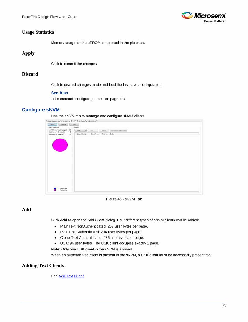
PolarFire Design Flow User Guide
76
Usage Statistics
Memory usage for the uPROM is reported in the pie chart.
Apply
Click to commit the changes.
Discard
Click to discard changes made and load the last saved configuration.
See Also Tcl command "configure_uprom" on page 124
Configure sNVM Use the sNVM tab to manage and configure sNVM clients.
Figure 46 · sNVM Tab
Add
Click Add to open the Add Client dialog. Four different types of sNVM clients can be added: • PlainText NonAuthenticated: 252 user bytes per page. • PlainText Authenticated: 236 user bytes per page. • CipherText Authenticated: 236 user bytes per page. • USK: 96 user bytes. The USK client occupies exactly 1 page.
Note: Only one USK client in the sNVM is allowed. When an authenticated client is present in the sNVM, a USK client must be necessarily present too.
Adding Text Clients
See Add Text Client

PolarFire Design Flow User Guide
77
Adding a USK Client
See Add USK Client
Edit
Use the Edit button to edit the SNVM client’s configuration. If there are multiple sNVM clients, first select the client you want and then click Edit. When changes are made to the configuration of any of the sNVM client, then their ‘Edited’ state is indicated by an asterisk (*) next to the sNVM tab’s title, and also an asterisk (*) next to the title of the main window of the Design and Memory Initialization step. When the edits are saved , then the sNVM tab’s asterisk (*) disappears. All the edits present in all the tab can be saved in one go by clicking on the ‘Save’ icon on Libero’s toolbar. When there are no edits present in any of the tabs, then the asterisk (*) next to the title of the main window disappears.
Delete
Use the Delete button to delete an sNVM client. If there are multiple sNVM clients, , first select the client you want and then click Delete.
Load Design Configuration
Click this button to load in the design’s original sNVM configuration file in <project>/component/work/sNVM.cfg. This button is grayed out if the design does not have an original sNVM configuration file. This configuration is changed whenever the design is updated in the design window, If there are changes made to this design configuration after the latest Apply, Libero SoC gives a clear visual indication that a newer design configuration is available by two means: • an info icon appears next to the button ‘Load design configuration’, • an info icon is shown next to the sNVM tab title.
The tool-tip on both icons contains the time-stamp information of the design configuration file. The icons disappear after the user clicks Apply the next time.
Usage Statistics
Memory usage for the sNVM is reported in the pie chart.
Apply
Click to commit the changes.
Discard
Click to discard changes made and load the last saved configuration.
See Also Tcl command configure_snvm PolarFire FPGA Programming User Guide
Configure SPI Flash The SPI Flash tab allows you to enable Auto Update, select the SPI Flash Manufacturer, and configure SPI flash clients. The configuration is saved in the spiflash.cfg file in the Libero design implementation folder.

PolarFire Design Flow User Guide
78
Figure 47 · SPI Flash Tab
Enable Auto Update
Check Enable Auto Update to enable Auto Update on the target device. The bitstream generated within Libero will enable this feature. If this is checked, a total of two SPI Bitstreams can be added. One SPI Bitstream will be for Auto Update and the other will be for Recovery/Golden. The tool enforces the Recovery/Golden bitstream to be at index 0 and the Auto Update bitstream to be at Index 1. The Auto Update Bitstream Design version must be greater than the design version of the Recovery/Golden bitstream.
Manufacturer
Click the pull-down menu to see the supported SPI Flash manufacturer/vendors and the part number. The table below lists the supported vendors and part number.
Manufacturer Part Number Capacity Sector Size
MICRON MT25QL01GBBB8ESF-0SIT 1GB 4KB
The SPI Flash Part Number is displayed to the right of the manufacturer/vendor name. The Memory size (in MB) for the SPI Flash is displayed in the Usage Statistics above the pie chart.
Usage Statistics
Available Memory (MB) reflects the SPI Flash vendor and part selected. • MICRON
Memory usage for the SPI Flash is reported in the pie chart.
SPI Flash Clients
SPI flash clients appear in a spreadsheet-like format when they are added and configured.
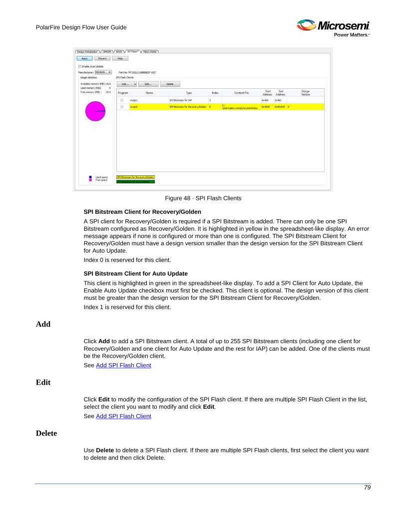
PolarFire Design Flow User Guide
79
Figure 48 · SPI Flash Clients
SPI Bitstream Client for Recovery/Golden A SPI client for Recovery/Golden is required if a SPI Bitstream is added. There can only be one SPI Bitstream configured as Recovery/Golden. It is highlighted in yellow in the spreadsheet-like display. An error message appears if none is configured or more than one is configured. The SPI Bitstream Client for Recovery/Golden must have a design version smaller than the design version for the SPI Bitstream Client for Auto Update. Index 0 is reserved for this client.
SPI Bitstream Client for Auto Update This client is highlighted in green in the spreadsheet-like display. To add a SPI Client for Auto Update, the Enable Auto Update checkbox must first be checked. This client is optional. The design version of this client must be greater than the design version for the SPI Bitstream Client for Recovery/Golden. Index 1 is reserved for this client.
Add
Click Add to add a SPI Bitstream client. A total of up to 255 SPI Bitstream clients (including one client for Recovery/Golden and one client for Auto Update and the rest for IAP) can be added. One of the clients must be the Recovery/Golden client. See Add SPI Flash Client
Edit
Click Edit to modify the configuration of the SPI Flash client. If there are multiple SPI Flash Client in the list, select the client you want to modify and click Edit. See Add SPI Flash Client
Delete
Use Delete to delete a SPI Flash client. If there are multiple SPI Flash clients, first select the client you want to delete and then click Delete.
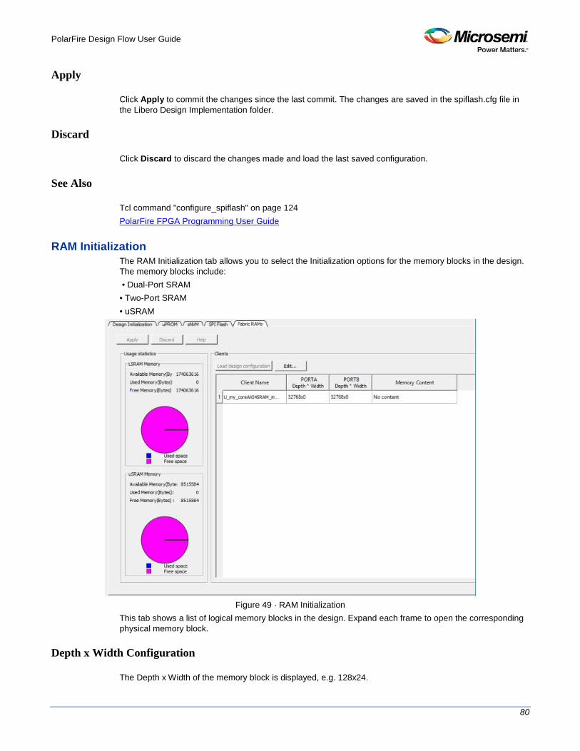
PolarFire Design Flow User Guide
80
Apply
Click Apply to commit the changes since the last commit. The changes are saved in the spiflash.cfg file in the Libero Design Implementation folder.
Discard
Click Discard to discard the changes made and load the last saved configuration.
See Also
Tcl command "configure_spiflash" on page 124 PolarFire FPGA Programming User Guide
RAM Initialization The RAM Initialization tab allows you to select the Initialization options for the memory blocks in the design. The memory blocks include: • Dual-Port SRAM • Two-Port SRAM • uSRAM
Figure 49 · RAM Initialization
This tab shows a list of logical memory blocks in the design. Expand each frame to open the corresponding physical memory block.
Depth x Width Configuration
The Depth x Width of the memory block is displayed, e.g. 128x24.

PolarFire Design Flow User Guide
81
Optimization Options
Memory blocks can be optimized for high speed or low power. Select the option that matches the selection in the configurator of the memory block.
Initialization Options
Three options are available: No content, Content Filled with Zeros and Memory File.
No Content The memory block is not initialized.
Content Filled with Zeros The memory block is filled with zeros for initialization.
Memory File Click the Browse button to navigate to the location of a memory file and import the file to the memory block. By default, the same memory file as specified in the memory configurator is used. The supported memory file formats are Intel-HEX (*.hex) or Motorola (*.s).
Load Design Configuration
Click to load the initial Design Configuration content. All the changes made in the current RAM Initialization tab are ignored (including the changes saved with the Apply button)
Apply
Click the Apply button to save the changes made in this tab. Note: The Apply button saves the changes only. For the initialization of the memory block to take effect, go back to the Device Initialization tab and click Generate Initialization Clients.
Discard
Click the Discard button to discard any changes made in this tab.
Generate Design Initialization Data To generate the initialization clients, do one of the following in the Design Flow window: • Double-click Generate Design Initialization Data or • Right-click Generate Design Initialization Data and choose Run
Libero SoC carries out the following three actions: • Generates the memory files corresponding to the three stages of the initialization sequence. • Removes all pre-existing initialization clients. • Creates the initialization clients for each stage and places them in their target memories.
• The first stage initialization client is always created, and is always placed in sNVM. It is always placed at start address 0xDC00 (page 220).
• The second stage initialization client is created only when there are PCIe blocks present in the design. It is always placed in sNVM. It is placed at the start address specified by the user in the ‘Design Initialization’ tab of the ‘Configure Design Initialization Data and Memories’ tool.

PolarFire Design Flow User Guide
82
• The third stage initialization client is created only when there are Fabric RAMs in the design or non-PCIe transceiver blocks in the design. It can be placed in any of uPROM, sNVM, or SPI memories at the user-specified start address. The user can specify both the target memory and the target start address in the ‘Design Initialization’ tab of the ‘Configure Design Initialization Data and Memories’ tool.
See Also Configure Design Initialization Data and Memories generate_design_initialization_data
Configure Hardware Programming Connectivity and Interface
In the Libero SoC Design Flow window, expand Configure Hardware and double-click Programming Connectivity and Interface to open the Programming Connectivity and Interface window. The Programming Connectivity and Interface window displays the physical chain from TDI to TDO configuration. The Programming Connectivity and Interface view enables the following actions: • Select Programming Mode – Select JTAG. or SPI Slave mode. SPI Slave mode is only supported by
FlashPro5.SPI Slave mode is not supported for PolarFire devices. • Construct Chain Automatically - Automatically construct the physical chain • Add Microsemi Device – Add a Microsemi device to the chain • Add Non-Microsemi Device – Add a non-Microsemi device to the chain • Add Microsemi Devices From Files – Add a Microsemi device from a programming file • Delete Selected Device – Delete selected devices in the grid • Scan and Check Chain – Scan the physical chain connected to the programmer and check if it
matches the chain constructed in the grid • Zoom In – Zoom into the grid • Zoom Out – Zoom out of the grid
Hover Information
The device tooltip displays the following information if you hover your pointer over a device in the grid: • Name - Editable field for a user-specified device name. If you have two or more identical devices in
your chain you can use this field to give them unique names. • Device - Device name. • File - Path to programming file. • Programming action – When a programming file is loaded, the user can select a programming action
for any device which is not the Libero design device. • IR Length - Device instruction length. • TCK - Maximum clock frequency in Hz to program a specific device; Libero uses this information to
ensure that the programmer operates at a frequency lower than the slowest device in the chain.

PolarFire Design Flow User Guide
83
Figure 50 · Device Information
Device Chain Details
The device within the chain has the following details: • Libero design device – Has a red circle within Microsemi logo. Libero design device cannot be
disabled. • Left/right arrow – Move device to left or right according to the physical chain. • Enable Device - Select to enable the device for programming; enabled devices are green, disabled
devices are gray. • Name - Displays your specified device name. • File - Path to programming file.
Right-Click Properties
• Set as Libero Design Device - The user needs to set Libero design device when there are multiple identical Libero design devices in the chain.
• Enable Device for Programming - Select to enable the device for programming; enabled devices are green, disabled devices are gray.
• Configure Device – Ability to reconfigure the device (for a Libero SoC target device the dialog appears but only the device name is editable).
• Load Programming File – Load programming file for selected device. (Not supported for Libero SoC target design device.)
• Set Serial Data - Opens the Serial Settings dialog box; enables you to set your serialization data. • Select Program Procedure/Actions (Not supported for Libero SoC target design device):
• Actions - List of programming actions for your device. • Procedures - Advanced option; enables you to customize the list of recommended and optional
procedures for the selected Action. • Move Device Left/Right – Move device in the chain to left or right.

PolarFire Design Flow User Guide
84
Figure 51 · Right-click Properties
Programmer Settings In the Libero SoC Design Flow window, expand Edit Design Hardware Configuration and double-click Programmer Settings to view the name, type, and port. The dialog box displays information about your programmer if it is connected.
Figure 52 · Programmer Settings for Connected Programmer
Click Edit Programmer Settings to view the Programmer Settings dialog box. You can set specific voltage and force TCK frequency values for your programmer in this dialog box.

PolarFire Design Flow User Guide
85
Figure 53 · Programmer Settings Dialog Box
The Programmer Settings dialog box includes setting options for FlashPro5/4/3/3X. Limitation of the TCK frequency for the selected programmer: • FlashPro5: 1, 2, 3, 4, 5, 6, 10, 15, 30 MHz • FlashPro4: 1, 2, 3, 4, 5, 6 MHz • FlashPro3/3X: 1, 2, 3, 4, 6 MHz
TCK frequency limits by target device: • Refer to target device data sheet
During execution, the frequency set by the FREQUENCY statement in the PDB/STAPL file overrides the TCK frequency setting selected by you in the Programmer Settings dialog box unless you also select the Force TCK Frequency checkbox.
FlashPro5/4/3/3X Programmer Settings
For FlashPro5/4/3/3X, you can choose the Set Vpump setting or the Force TCK Frequency. If you choose the Force TCK Frequency, select the appropriate MHz frequency. For FlashPro4/3X settings, you can switch the TCK mode between Free running clock and Discrete clocking. After you have made your selections(s), click OK.
Default Settings • The Vpump option is checked to instruct the FlashPro5/4/3/3X programmer(s) to supply Vpump to the
device. • The Force TCK Frequency option is unchecked to instruct the FlashPro5/4/3/3X to use the TCK
frequency specified by the Frequency statement in the PDB/STAPL file(s). • FlashPro5/4/3/3X default TCK mode setting is Free running clock.
Alert: Do not connect VPUMP to a PolarFire device.

PolarFire Design Flow User Guide
86
Device I/O States During Programming -- JTAG Mode Only In the Libero SoC Design Flow window expand Edit Design Hardware Configuration and double-click Device I/O states during programming to specify the I/O states prior to programming. In Libero SoC, this feature is only available once Layout is completed. The default state for all I/Os is Tri-state.
To specify I/O states during programming: 1. Sort the pins as desired by clicking any of the column headers to sort the entries by that header. Select
the I/Os you wish to modify (as shown in the figure below). 2. Set the I/O Output state. You can set Basic I/O settings if you want to use the default I/O settings for
your pins, or use Custom I/O settings to customize the settings for each pin. See the Specifying I/O States During Programming - I/O States and BSR Details help topic for more information on setting your I/O state and the corresponding pin values. Basic I/O state settings are: • 1 – I/O is set to drive out logic High • 0 – I/O is set to drive out logic Low • Last Known State: I/O is set to the last value that was driven out prior to entering the
programming mode, and then held at that value during programming • Z - Tri-State: I/O is tristated
Figure 54 · I/O States During Programming Window
3. Click OK to save your settings. Note: I/O States During programming will be used during programming or when exporting the bitstream.
Configure Programming Options Sets your Design Version and Silicon Signature. Design name is a read-only field that identifies your design. Design Version (number between 0 and 65535) - Specifies the design version to be programmed to the device. This field is also used for Back-level protection in "Update Policy" on page 90 of the Configure Security Wizard. Silicon signature (max length is 8 HEX chars) - 32-bit user configurable silicon signature to be programmed into the device. This field can be read from the device using the JTAG (IEEE 1149-1) USERCODE instruction or by running the DEVICE_INFO programming action.

PolarFire Design Flow User Guide
87
Figure 55 · Configure Programming Options Dialog Box
Notes SPI file programming for Auto Programming, Auto Update (IAP) and IAP/ISP Services currently can only program security once with the master file. Update files cannot update the security settings. In addition, Silicon Signature, and Tamper Macro can only be programmed with the master file and cannot be updated.
Configure Security Configure Security Wizard
The Configure Security Wizard is a GUI-based wizard that guides the user step by step on how to configure custom security settings. The wizard has five steps executed in this sequential order:
1. User keys 2. Update Policy 3. Debug Policy 4. Microsemi Policy 5. JTAG/SPI Slave Commands

PolarFire Design Flow User Guide
88
Figure 56 · Configure Security Wizard
Summary Window
The summary window displays the summary of the current configuration settings. The window will scroll to the current page as you move from page to page.
Security Key Mode
Two security key modes are available. • Bitstream encryption with default key
This mode uses the default encryption key for security. The Next and Back button are disabled. All steps are disabled. Custom User Keys and security settings are disabled.
• Custom security Mode This mode allows you to configure custom security keys and settings. All steps are enabled. The Next and Back button are enabled.
Back
Click Back to return to the previous step.
Next
Click Next to proceed to the next step.

PolarFire Design Flow User Guide
89
Finish
Click Finish to skip steps and complete the configuration.
Save Summary to File
Click Save Summary to File to save the display in the Summary field to a file.
User Keys The User Keys are configured in this step. All keys are 256 bits (64 HEX characters).
Figure 57 · User Keys
User Key Set 1 (UKS1)
UKS1 is enabled by default. This key protects all security settings. This key is required and must be a string of 64 HEX characters. Enter the key or click the padlock icon at the far right to generate a random key.

PolarFire Design Flow User Guide
90
User Encryption Key 1 (UEK1)
UEK1 is enabled by default. Click Disable if you want to disable it. If enabled, the key is required and must be a string of 64 HEX characters. Enter the key or click the padlock icon at the far right to generate a random key. Use UEK1 for updating the Fabric, uPROM, and sNVM or disable it.
User Encryption Key 2 (UEK2)
UEK2 is enabled by default. Click Disable if you want to disable it. If enabled, the key is required and must be a string of 64 HEX characters. Enter the key or click the padlock icon at the far right to generate a random key. Use UEK2 as a second encryption key for updating the Fabric, uPROM, and sNVM or disable it
User Pass Key 2 (UPK2)
UPK2 is required if UEK2 is enabled. Enter the key or click the padlock icon at the far right to generate a random key.
Update Policy Field updates are enabled by default. Use this page to disable field updates and to specify field-update protection parameters.
Figure 58 · Update Policy

PolarFire Design Flow User Guide
91
Fabric update protection
Two options are available: • Disable Erase/Write operations WARNING: The field update STAPL files (_uek1/_uek2) will include plain-text FlashLock/UPK1 • Updates allowed using user defined encryption keys; FlashLock/UPK1 is not required for updates
sNVM update protection options:
Two options are available: • Disable Write operations WARNING: The field update STAPL files (_uek1/_uek2) will include plain-text FlashLock/UPK1 • Updates allowed using user defined ecnryption keys; FlashLock/UPK1 is not required for updates
Back Level protection
When enabled, a design being programmed must be of a version higher than the Back Level version value in the programmed device. This limits the design versions that the device can update. Only programming bitstreams with Designer Version greater than the Back Level version are allowed for programming.
Design version (number between 0 to 65535) Displays the current Design version (as set in the Configure Programming Options tool).
Back Level version (number between 0 to 65535) Back level uses the Design version value to determine which bitstreams are allowed for programming. The Back level version must be smaller than Design version. If not, a warning message appears.
Disable programming interfaces
The following programming interfaces can be disabled • Auto Programming and IAP services • JTAG • SPI Slave
When all programming interfaces have been disabled, the device becomes one-time programmable (OTP). The following error message is displayed: "Device will not be reprogrammable because all programming interfaces have been permanently disabled. The device is one-time programmable(OTP). To configure one-time programmable security, use the Configure OTP Security tool."
Disable Bitstream Programming Actions (JTAG/SPI Slave)
• Program • Authenticate • Verify WARNING: The field update STAPL files (_uek1/_uek2) will include plain-text FlashLock/UPK1 The summary at the top of the wizard summarizes the result of the selection.

PolarFire Design Flow User Guide
92
Reset to Default
Reset the options to default values. All options are unchecked.
Debug Policy The Debug Policy page allows you to configure Debug Protections. By default, debugging is enabled.
Debug with DPK (Debug Pass Key) - Optional
Protect Debug with a 256-bit (64-character HEX) Debug Pass Key. Enter the key in the field or click the padlock icon at the far right to generate a random key. This key is optional if you want a separate passkey to enable access to disabled debug features during one debugging session. If the DPK key is entered, then at least one option must be checked.
Figure 59 · Debug Policy
SmartDebug Access Control
All of the following are enabled by default for SmartDebug access. Check to disable access. • Disable User Debug Access and Active Probe • Disable Live Probe • Disable sNVM

PolarFire Design Flow User Guide
93
WARNING: Leaving SmartDebug access control enabled on production devices will allow anyone to debug or access active probes, access Live Probe, or read the content of sNVM. Three additional options are: • Disable UJTAG command through JTAG Interface • Disable JTAG (1149.1) boundary scan
Disables JTAG (1149.1) commands. The following JTAG commands will be disabled: HIGHZ, EXTEST, INTEST, CLAMP, SAMPLE, and PRELOAD. I/Os will be tri-stated when in JTAG programming mode and BSR control during programming is disabled. BYPASS, IDCODE, and USERCODE instructions will remain functional.
• Disable reading temperature and voltage sensor (JTAG/SPI Slave) The summary at the top of the page displays the results of the selection.
Microsemi Factory Access Policy The page allows you to configure the policy for Microsemi Test Mode Access. Test mode access is required for Failure Analysis on the device.
Figure 60 · Microsemi Access Policy
Two options are available: • Allow factory test mode access (default setting).
WARNING: This is not recommended for production devices. • Disable factory test mode access
NOTE: Use FlashLock/UPK1 to change access level

PolarFire Design Flow User Guide
94
JTAG/SPI Slave Command Policy The page allows you to configure the policy for JTAG/SPI Slave User Commands. Three options are available. Enabled is the default setting for all three options. Click the checkbox to disable any of the settings. • Disable all external access to PUF emulation through JTAG/SPI Slave • Disable external Fabric/sNVM digest requests through JTAG/SPI Slave
WARNING: Repeated external Fabric digest calculations can impact device reliability. View Datasheet for additional information.
• Disable external zeroization through JTAG/SPI Slave WARNING: It is not recommended to leave zeroization enabled for production devices
Figure 61 · JTAG/SPI Slave Commands Policy
Security Features Frequently Asked Questions I have configured the Security Wizard and enabled security in my design but I do not want to program my design with the Security Policy Manager features enabled. What do I do? Go to Configure Bitstream and uncheck Security. What is programmed when I click Program Device? All features configured in your design and enabled in the Configure Bitstream tool. Any features you have configured (such as sNVM or Security) are enabled for programming by default. When I click Program Device is the programming file encrypted? All programming files are encrypted. To generate programming files encrypted with UEK1 or UEK2 you must generate them from Export Bitstream for field updates. Note: Once security is programmed, you must erase the security before attempting to reprogram the
security.
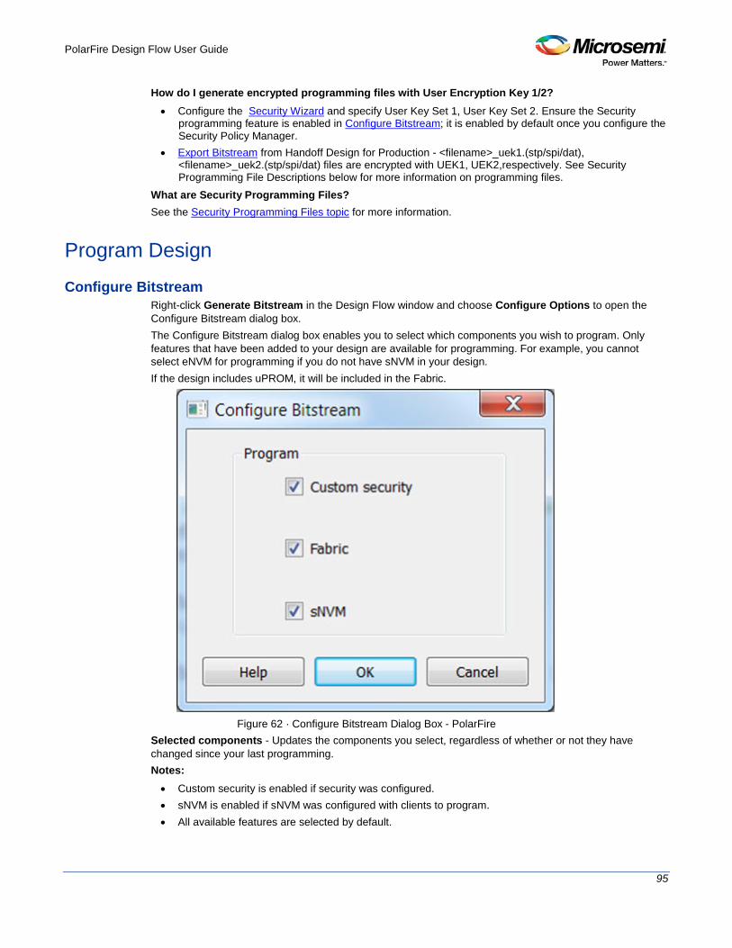
PolarFire Design Flow User Guide
95
How do I generate encrypted programming files with User Encryption Key 1/2? • Configure the Security Wizard and specify User Key Set 1, User Key Set 2. Ensure the Security
programming feature is enabled in Configure Bitstream; it is enabled by default once you configure the Security Policy Manager.
• Export Bitstream from Handoff Design for Production - <filename>_uek1.(stp/spi/dat), <filename>_uek2.(stp/spi/dat) files are encrypted with UEK1, UEK2,respectively. See Security Programming File Descriptions below for more information on programming files.
What are Security Programming Files? See the Security Programming Files topic for more information.
Program Design Configure Bitstream
Right-click Generate Bitstream in the Design Flow window and choose Configure Options to open the Configure Bitstream dialog box. The Configure Bitstream dialog box enables you to select which components you wish to program. Only features that have been added to your design are available for programming. For example, you cannot select eNVM for programming if you do not have sNVM in your design. If the design includes uPROM, it will be included in the Fabric.
Figure 62 · Configure Bitstream Dialog Box - PolarFire
Selected components - Updates the components you select, regardless of whether or not they have changed since your last programming. Notes: • Custom security is enabled if security was configured. • sNVM is enabled if sNVM was configured with clients to program. • All available features are selected by default.

PolarFire Design Flow User Guide
96
See Also Note: "Generate Bitstream " on page 96
Generate Bitstream Generates the bitstream for use with the Run PROGRAM Action tool. The tool incorporates the Fabric design, sNVM configuration (if configured) and security settings (if configured) to generate the bitstream file. You need to configure the bitstream before you generate the bitstream. Right-click Generate Bitstream and choose Configure Options to open the Configure Bitstream dialog box to select which components you wish to program. Only features that have been added to your design are available for programming. For example, you cannot select sNVM for programming if you do not have an sNVM in your design. If the design includes UPROM, it will be included in the Fabric. Modifications to the Fabric design, sNVM configuration, or security settings will invalidate this tool and require regeneration of the bitstream file. The Fabric programming data will only be regenerated if you make changes to the Fabric design, such as in the Create Design, Create Constraints and Implement Design sections of the Design Flow window. When the process is complete a green check appears next to the operation in the Design Flow window (as shown in the figure below) and information messages appear in the Log window.
Figure 63 · Generate Bitstream (Complete)
See also Configure Bitstream Dialog Box
Run PROGRAM Action If you have a device programmer connected, you can double-click Run PROGRAM Action to execute your programming in batch mode with default settings. If your programmer is not connected, or if your default settings are invalid, the Reports view lists the error(s). Right-click Run PROGRAM Action and choose Configure Action/Procedures to open the Select Action and Procedures dialog box.
Programming File Actions Libero SoC enables you to program security settings, FPGA Array, and sNVM features. Note: If the design includes UPROM, it will be included in the Fabric. You can program these features separately using different programming files or you can combine them into one programming file. In the Design Flow window, expand Program Design, click Run PROGRAM Action, and right-click Configure Actions/Procedures.

PolarFire Design Flow User Guide
97
Figure 64 · Select Actions and Procedures
Left-click on the Action: picklist to select from the following actions:
Figure 65 · Action Choices
The following table lists programming file actions and supported procedures. Table 1 · Programming File Actions and Supported Procedures
Action Procedures
DEVICE_INFO VERIFY_IDCODE DO_DEVICE_INFO DO_EXIT
ENC_DATA_AUTHENTICATION VERIFY_IDCODE DO_AUTHENTICATION DO_EXIT
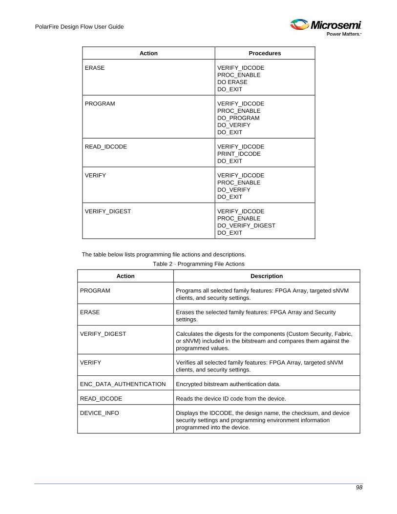
PolarFire Design Flow User Guide
98
Action Procedures
ERASE VERIFY_IDCODE PROC_ENABLE DO ERASE DO_EXIT
PROGRAM VERIFY_IDCODE PROC_ENABLE DO_PROGRAM DO_VERIFY DO_EXIT
READ_IDCODE VERIFY_IDCODE PRINT_IDCODE DO_EXIT
VERIFY VERIFY_IDCODE PROC_ENABLE DO_VERIFY DO_EXIT
VERIFY_DIGEST VERIFY_IDCODE PROC_ENABLE DO_VERIFY_DIGEST DO_EXIT
The table below lists programming file actions and descriptions.
Table 2 · Programming File Actions
Action Description
PROGRAM Programs all selected family features: FPGA Array, targeted sNVM clients, and security settings.
ERASE Erases the selected family features: FPGA Array and Security settings.
VERIFY_DIGEST Calculates the digests for the components (Custom Security, Fabric, or sNVM) included in the bitstream and compares them against the programmed values.
VERIFY Verifies all selected family features: FPGA Array, targeted sNVM clients, and security settings.
ENC_DATA_AUTHENTICATION Encrypted bitstream authentication data.
READ_IDCODE Reads the device ID code from the device.
DEVICE_INFO Displays the IDCODE, the design name, the checksum, and device security settings and programming environment information programmed into the device.
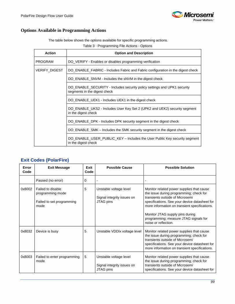
PolarFire Design Flow User Guide
99
Options Available in Programming Actions
The table below shows the options available for specific programming actions. Table 3 · Programming File Actions - Options
Action Option and Description
PROGRAM DO_VERIFY - Enables or disables programming verification
VERIFY_DIGEST DO_ENABLE_FABRIC - Includes Fabric and Fabric configuration in the digest check
DO_ENABLE_SNVM - Includes the sNVM in the digest check
DO_ENABLE_SECURITY - Includes security policy settings and UPK1 security segments in the digest check
DO_ENABLE_UEK1 - Includes UEK1 in the digest check
DO_ENABLE_UKS2 - Includes User Key Set 2 (UPK2 and UEK2) security segment in the digest check
DO_ENABLE_DPK - Includes DPK security segment in the digest check
DO_ENABLE_SMK – Includes the SMK security segment in the digest check
DO_ENABLE_USER_PUBLIC_KEY – Includes the User Public Key security segment in the digest check
Exit Codes (PolarFire) Error Code
Exit Message Exit Code
Possible Cause Possible Solution
Passed (no error) 0 - -
0x8002 Failed to disable programming mode Failed to set programming mode
5 Unstable voltage level Signal integrity issues on JTAG pins
Monitor related power supplies that cause the issue during programming; check for transients outside of Microsemi specifications. See your device datasheet for more information on transient specifications. Monitor JTAG supply pins during programming; measure JTAG signals for noise or reflection.
0x8032 Device is busy 5 Unstable VDDIx voltage level Monitor related power supplies that cause the issue during programming; check for transients outside of Microsemi specifications. See your device datasheet for more information on transient specifications.
0x8003 Failed to enter programming mode
5 Unstable voltage level Signal integrity issues on JTAG pins
Monitor related power supplies that cause the issue during programming; check for transients outside of Microsemi specifications. See your device datasheet for

PolarFire Design Flow User Guide
100
Error Code
Exit Message Exit Code
Possible Cause Possible Solution
DEVRST_N is tied to LOW
more information on transient specifications. Monitor JTAG supply pins during programming; measure JTAG signals for noise or reflection. Tie DEVRST_N to HIGH prior to programming the device.
0x8004 Failed to verify IDCODE 6 Incorrect programming file Incorrect device in chain Signal integrity issues on JTAG pins
Choose the correct programming file and select the correct device in the chain. Measure JTAG pins and noise for reflection. If TRST is left floating then add pull-up to pin. Reduce the length of Ground connection.
0x8005 0x8006 0x8007 0x8008
Failed to verify FPGA Array Failed to verify Fabric Configuration Failed to verify Security Failed to verify sNVM
11 Device is programmed with a different design or the component is blank. Unstable voltage level. Signal integrity issues on JTAG pins.
Verify the device is programmed with the correct data/design. Monitor related power supplies that cause the issue during programming; check for transients outside of Microsemi specifications. See your device datasheet for more information on transient specifications. Monitor JTAG supply pins during programming; measure JTAG signals for noise or reflection.
0x8013 External digest check via JTAG/SPI Slave is disabled.
-18 External Digest check via JTAG/SPI Slave is disabled.
Need to use a bitstream file which has a valid FlashLock/UPK1 to enable external digest check via JTAG/SPI Slave.
0x8015 FPGA Fabric digest verification: FAIL Deselect procedure 'DO_ENABLE_FABRIC' to remove this digest check.
-20 FPGA Fabric is either erased or the data has been corrupted or tampered with
If the Fabric is erased, deselect procedure "DO_ENABLE_FABRIC" from action "VERIFY_DIGEST"
0x8016 sNVM digest verification: FAIL Deselect procedure 'DO_ENABLE_SNVM' to remove this digest check.
-20 sNVM is either erased or the data has been corrupted or tampered with
If the sNVM is erased, deselect procedure "DO_ENABLE_SNVM" from action "VERIFY_DIGEST"
0x8018 User security policices segment digest verification: FAIL Deselect procedure 'DO_ENABLE_SECURITY' to remove this digest check.
-20 Security segment is either erased or the data has been corrupted or tampered with
If the security is erased, deselect procedure "DO_ENABLE_SECURITY" from action "VERIFY_DIGEST"

PolarFire Design Flow User Guide
101
Error Code
Exit Message Exit Code
Possible Cause Possible Solution
0x8019 UPK1 segment digest verification: FAIL Deselect procedure 'DO_ENABLE_SECURITY' to remove this digest check.
-20 UPK1 segment is either erased or the data has been corrupted or tampered with
If the UPK1 is erased, deselect procedure "DO_ENABLE_SECURITY" from action "VERIFY_DIGEST"
0x801A UPK2 segment digest verification: FAIL Deselect procedure 'DO_ENABLE_UKS2' to remove this digest check.
-20 UPK2 segment is either erased or the data has been corrupted or tampered with
If the UPK2 is erased, deselect procedure "DO_ENABLE_UKS2" from action "VERIFY_DIGEST"
0x801B Factory row and factory key segment digest verification: FAIL
-20 Factory row and factory key segment have been erased through zeroization or the data has been corrupted or tampered with
0x801C Fabric configuration segment digest verification: FAIL Deselect procedure 'DO_ENABLE_FABRIC' to remove this digest check.
-20 Fabric configuration segment is either erased or has been corrupted or tampered with
If the Fabric configuration is erased, deselect procedure "DO_ENABLE_FABRIC" from action "VERIFY_DIGEST"
0x8052 UEK1 segment digest verification: FAIL Deselect procedure 'DO_ENABLE_UEK1' to remove this digest check.
-20 UEK1 segment is either erased or the data has been corrupted or tampered with
If the UEK1 is erased, deselect procedure "DO_ENABLE_UEK1" from action "VERIFY_DIGEST"
0x8053 UEK2 segment digest verification: FAIL Deselect procedure 'DO_ENABLE_UEK2' to remove this digest check.
-20 UEK2 segment is either erased or the data has been corrupted or tampered with
If the UEK2 is erased, deselect procedure "DO_ENABLE_UEK2" from action "VERIFY_DIGEST"
0x8054 DPK segment digest verification: FAIL Deselect procedure 'DO_ENABLE_DPK' to remove this digest check.
-20 DPK segment is either erased or the data has been corrupted or tampered with
If the DPK is erased, deselect procedure "DO_ENABLE_DPK" from action "VERIFY_DIGEST"
0x8057 SMK segment digest verification: FAIL
-20 SMK segment is either erased or the data has been corrupted or tampered with
If the SMK is erased, deselect procedure "DO_ENABLE_SMK" from action "VERIFY_DIGEST"
0x8058 User Public Key segment digest verification: FAIL
-20 User Public Key segment is either erased or the data has
If the User Public Key is erased, deselect procedure

PolarFire Design Flow User Guide
102
Error Code
Exit Message Exit Code
Possible Cause Possible Solution
been corrupted or tampered with
"DO_ENABLE_USER_PUBLIC_KEY" from action "VERIFY_DIGEST"
0x801D Device security prevented operation
-21 The device is protected with user pass key 1 and the bitstream file does not contain user pass key 1. User pass key 1 in the bitstream file does not match the device.
Run DEVICE_INFO to view security features that are protected. Provide a bitstream file with a user pass key 1 that matches the user pass key 1 programmed into the device.
0x801F Programming Error. Bitstream or data is corrupted or noisy
-22 Bitstream file has been corrupted or was incorrectly generated. Unstable voltage level. Signal integrity issues on JTAG pins.
Regenerate bitstream file Monitor related power supplies that cause the issue during programming; check for transients outside of Microsemi specifications. See your device datasheet for more information on transient specifications. Monitor JTAG supply pins during programming; measure JTAG signals for noise or reflection.
0x8021 Programming Error. Invalid/Corrupted encryption key
-23 File contains an encrypted key that does not match the device File contains user encryption key, but device has not been programmed with the user encryption key
Provide a programming file with an encryption key that matches that on the device First program security with master programming file, then program with user encryption 1/2 field update programming files
0x8023 Programming Error. Back level not satisfied
-24 Design version is not higher than the back-level programmed device
Generate a programming file with a design version higher than the back level version
0x8001 Failure to read DSN -24 Device is in System Controller Suspend Mode Check board connections
TRSTB should be driven High or disable "System Controller Suspend Mode".
0x8027 Programming Error. Insufficient device capabilities
-26 Device does not support the capabilities specified in programming file
Generate a programming file with the correct capabilities for the target device
0x8029 Programming Error. Incorrect DEVICEID
-27 Incorrect programming file Incorrect device in chain Signal integrity issues on JTAG pins
Choose the correct programming file and select the correct device in chain Measure JTAG pins and noise or reflection. If TRST is left floating, then add pull-up to pin Reduce the length of ground connection
0x802B Programming Error. -28 Programming file version is Generate programming file with latest
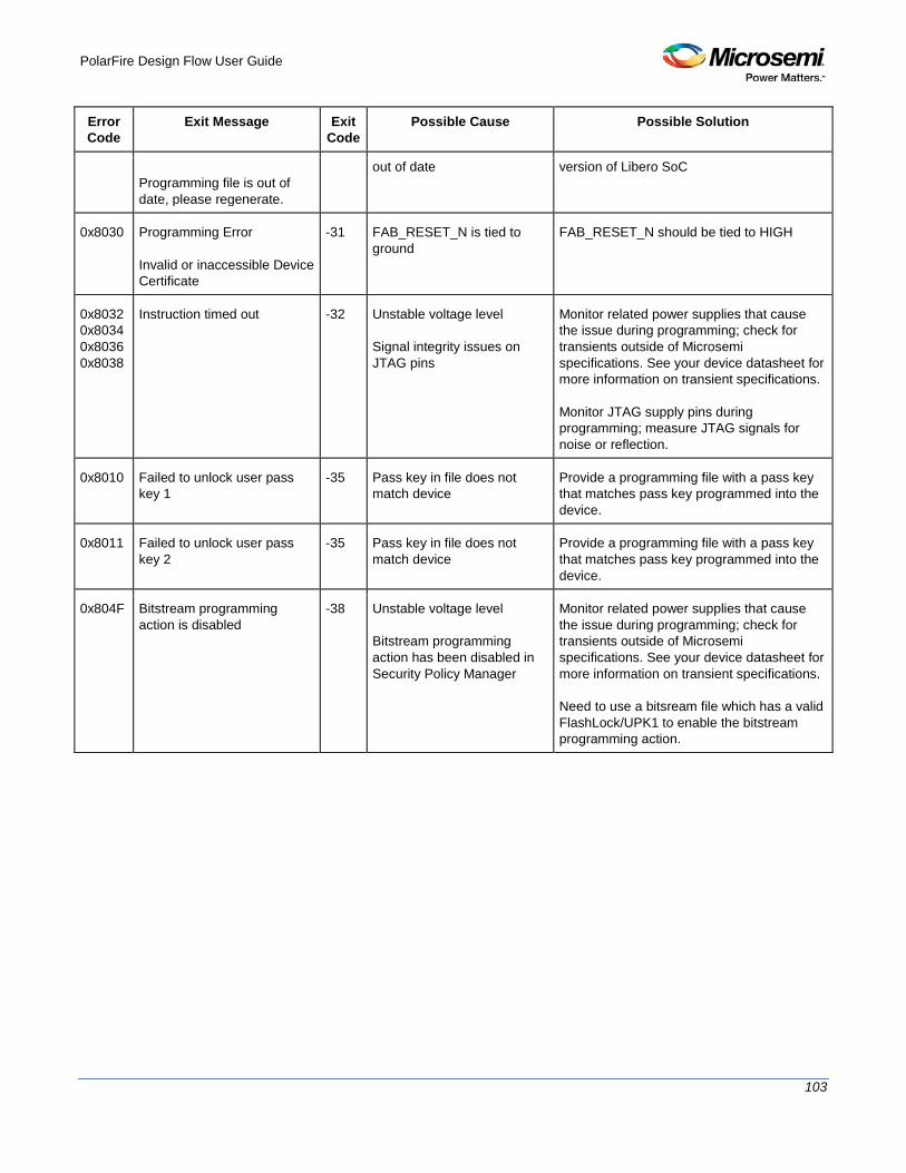
PolarFire Design Flow User Guide
103
Error Code
Exit Message Exit Code
Possible Cause Possible Solution
Programming file is out of date, please regenerate.
out of date version of Libero SoC
0x8030 Programming Error Invalid or inaccessible Device Certificate
-31 FAB_RESET_N is tied to ground
FAB_RESET_N should be tied to HIGH
0x8032 0x8034 0x8036 0x8038
Instruction timed out -32 Unstable voltage level Signal integrity issues on JTAG pins
Monitor related power supplies that cause the issue during programming; check for transients outside of Microsemi specifications. See your device datasheet for more information on transient specifications. Monitor JTAG supply pins during programming; measure JTAG signals for noise or reflection.
0x8010 Failed to unlock user pass key 1
-35 Pass key in file does not match device
Provide a programming file with a pass key that matches pass key programmed into the device.
0x8011 Failed to unlock user pass key 2
-35 Pass key in file does not match device
Provide a programming file with a pass key that matches pass key programmed into the device.
0x804F Bitstream programming action is disabled
-38 Unstable voltage level Bitstream programming action has been disabled in Security Policy Manager
Monitor related power supplies that cause the issue during programming; check for transients outside of Microsemi specifications. See your device datasheet for more information on transient specifications. Need to use a bitsream file which has a valid FlashLock/UPK1 to enable the bitstream programming action.

PolarFire Design Flow User Guide
104
Program SPI Flash Image Generate SPI Flash Image
This tool generates the <design>_spi_flash.bin file in the implementation folder. To run this tool; under the Program SPI Flash Image, right-click Generate SPI Flash Image and choose Run.
This tool depends on the Configure Design Initialization Data and Memories tool and the Generate Design Initialization Data tool. When running, the tool verifies that the SPI Flash configuration data is saved and valid; and that the SPI Flash initialization client was generated successfully (if required).
Run PROGRAM_SPI_FLASH Action This tool allows the user to program the SPI Flash device connected to the PolarFire device through the JTAG programming interface. Currently, only the Micron 1Gb SPI flash is supported, and is included with the Evaluation Kit. This feature minimizes cost by not requiring a mux and external SPI pins on the board for SPI flash programming by another tool. This tool always erases the entire SPI flash prior to programming. Programming starts at address 0 of the SPI flash until the last client. Any gaps in the SPI flash are programmed with all 1’s. Future versions of the software will allow the user to add Data Storage clients to program user data and will also provide the ability to partially update the SPI flash.
Note: The SPI pins are controlled by the Boundary Scan Register one bit at a time.
Figure 66 · SPI Flash Programming with PolarFire Device

PolarFire Design Flow User Guide
105
The following table provides the expectations of programming the SPI flash with a FP5 programmer. Future programmers are planned, and should greatly improve programming times.
SPI Size
ERASE
PROGRAM
VERIFY/READ
TCK Programmer
1 MPF300 SPI
Bitstream 9 MB 3:55 0:17:22 2:46:29 4MHz
FP5
Full Chip 128 MB
3:55 4:15:50 38:58:42 4MHz
FP5
Recommendations:
1. Since the verify time is currently not optimized, it is recommended to authenticate the SPI bitstreams with system services for quicker verification.
2. Since this tool erases the SPI flash prior to programming and currently does not support Data Storage clients for user data, it is recommended to program the SPI flash with Libero prior to programming other data on the SPI flash.
3. Since programming time is currently not optimized, it is recommended to not have huge gaps between clients in the SPI flash, since gaps are currently programmed with 1’s.
If SPI Flash is configured, you can execute Run PROGRAM_SPI_FLASH Action and select SPI Flash Image actions and procedures. In the Design Flow window, under Program SPI Flash Image, right-click Run PROGRAM_SPI_Flash Action and choose Configure Action/Procedures.
Note: In this release, SPI Flash programming is supported for MICRON devices only. See Configure SPI Flash Image Actions and Procedures for information about supported actions and procedures.
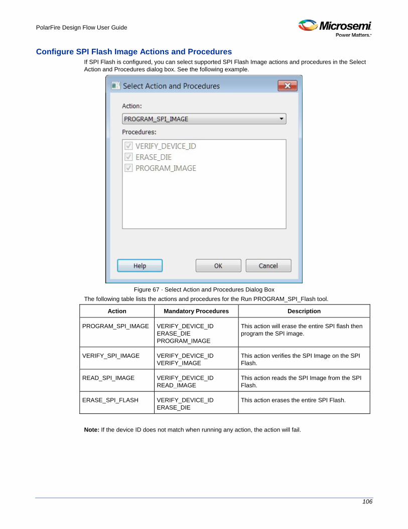
PolarFire Design Flow User Guide
106
Configure SPI Flash Image Actions and Procedures If SPI Flash is configured, you can select supported SPI Flash Image actions and procedures in the Select Action and Procedures dialog box. See the following example.
Figure 67 · Select Action and Procedures Dialog Box
The following table lists the actions and procedures for the Run PROGRAM_SPI_Flash tool.
Action Mandatory Procedures Description
PROGRAM_SPI_IMAGE VERIFY_DEVICE_ID ERASE_DIE PROGRAM_IMAGE
This action will erase the entire SPI flash then program the SPI image.
VERIFY_SPI_IMAGE VERIFY_DEVICE_ID VERIFY_IMAGE
This action verifies the SPI Image on the SPI Flash.
READ_SPI_IMAGE VERIFY_DEVICE_ID READ_IMAGE
This action reads the SPI Image from the SPI Flash.
ERASE_SPI_FLASH VERIFY_DEVICE_ID ERASE_DIE
This action erases the entire SPI Flash.
Note: If the device ID does not match when running any action, the action will fail.
PolarFire Design Flow User Guide
107
Debug Design SmartDebug
Design debug is a critical phase of FPGA design flow. Microsemi’s SmartDebug tool complements design simulation by allowing verification and troubleshooting at the hardware level. SmartDebug can provide access to Microsemi FPGA device's built-in probe logic, which enables designers to check the state of inputs and outputs in real-time without re-layout of the design. SmartDebug can be run in two modes: • Integrated mode from the Libero Design Flow • Standalone mode
Integrated Mode When run in integrated mode from Libero, SmartDebug can access all design and programming hardware information. No extra setup step is required. In addition, the Probe Insertion feature is available in Debug FPGA Array. To open SmartDebug in the Libero Design Flow window, expand Debug Design and double-click SmartDebug Design.
Standalone Mode SmartDebug can be installed separately in the setup containing FlashPro, FlashPro Express, and Job Manager. This provides a lean installation that includes all the programming and debug tools to be installed in a lab environment for debug. In this mode, SmartDebug is launched outside of the Libero Design Flow. Prior to launch of SmartDebug standalone mode, you must to go through SmartDebug project creation and import a Design Debug Data Container (DDC) file, exported from Libero, to access all debug features in the supported devices. Note: In standalone mode, the Probe Insertion feature is not available in FPGA Array Debug, as it requires incremental routing to connect the user net to the specified I/O.
See Also
SmartDebug User Guide
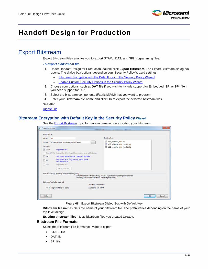
PolarFire Design Flow User Guide
108
Handoff Design for Production
Export Bitstream Export Bitstream Files enables you to export STAPL, DAT, and SPI programming files.
To export a bitstream file 1. Under Handoff Design for Production, double-click Export Bitstream. The Export Bitstream dialog box
opens. The dialog box options depend on your Security Policy Wizard settings: • Bitstream Encryption with the Default Key in the Security Policy Wizard • Enable Custom Security Options in the Security Policy Wizard
2. Choose your options, such as DAT file if you wish to include support for Embedded ISP, or SPI file if you need support for IAP.
3. Select the bitstream components (Fabric/sNVM) that you want to program. 4. Enter your Bitstream file name and click OK to export the selected bitstream files.
See Also Digest File
Bitstream Encryption with Default Key in the Security Policy Wizard See the Export Bitstream topic for more information on exporting your bitstream.
Figure 68 · Export Bitstream Dialog Box with Default Key
Bitstream file name - Sets the name of your bitstream file. The prefix varies depending on the name of your top-level design. Existing bitstream files - Lists bitstream files you created already.
Bitstream File Formats: Select the Bitstream File format you want to export: • STAPL file • DAT file • SPI file

PolarFire Design Flow User Guide
109
Selected Security options (modify via "Configure Security Wizard " on page 87 – Gives a brief description of current security options. Bitstream files to be exported – Lists all the bitstream files that will be exported. File to program at trusted facility – Click to include Fabric and/or sNVM into the bitstream files to be programmed at a trusted facility. Note: Only features that have been added to your design are available for programming. For example, you
cannot select sNVM for programming if you do not have an sNVM in your design.
Enable Custom Security Options in the Security Policy Wizard See the Export Bitstream topic for information on exporting your bitstream.
Figure 69 · Export Bitstream Dialog Box with Enable Custom Security Options in the Security Policy Wizard
Bitstream file - Sets the name of your bitstream file. The prefix varies depending on the name of your top-level design. Existing files: - Lists bitstream files you created already. Formats: Select the Bitstream file format you want to export: • STAPL file • DAT file • SPI file
Selected Security options (modify via "Configure Security Wizard " on page 87 ) – Gives a brief description of current security options. Bitstream files to be exported – Lists all the bitstream files that will be exported. Note: If a component (for example, sNVM) is not present in design then it will be disabled in the bitstream component selection. Master file to program at trusted facility – Click to include Fabric and/or sNVM into the bitsream files to be programmed at a trusted facility. Note that Security is always programmed in Master file.

PolarFire Design Flow User Guide
110
File encrypted with UEK1 to program at untrusted facility or for Broadcast field update – Click to include Fabric and/or sNVM into the bitsream files to be programmed. If the selected features are not protected by UPK1, the bitstream can be programmed at untrusted location, since it is encrypted with UEK1 that is preprogrammed into the device. File encrypted with UEK2 to program at untrusted facility or for Broadcast field update - Click to include Fabric and/or sNVM into the bitsream files to be programmed. If the selected features are not protected by UPK1, the bitstream can be programmed at untrusted location, since it is encrypted with UEK2 that is preprogrammed into the device. Note: If the sNVM/Fabric is protected with UPK1 and included in the bitstream, UPK1 will be added to the STAPL and DAT file, and cannot be used at untrusted location. Note: If sNVM/Fabric is One Time Programmable, it precluded from bitstream encrypted with UEK1/2.
Security Programming Files Export Bitstream (expand Handoff Design for Production in the Design Flow window) creates the following files: <filename>_master.(stp/spi/dat) - Created when Enable custom security options is specified in the Security Wizard. This is the master programming file; it includes all programming features enabled, User Key Set 1, User Key Set 2 (optionally if specified), and your security policy settings. <filename>_security_only_master.(stp/spi/dat) – Created when Enable custom security options is specified in the Security Wizard. Master security programming file; includes User Key Set 1, User Key Set 2 (optionally if specified), and your security policy settings. <filename>_uek1.(stp/spi/dat) – Programming file encrypted with User Encryption Key 1 used for field updates; includes all your features for programming except security . <filename>_uek2.(stp/spi/dat) – Programming file encrypted with User Encryption Key 2 used for field updates; includes all your features for programming except security.

PolarFire Design Flow User Guide
111
Export FlashPro Express Job For PolarFire, Security Programming is supported. Use the Configure Security Wizard to configure Security before you export the programming job. The Export FlashPro Express Job dialog box displays the Security Options you have configured in the Configure Security Wizard. The Export FlashPro Express Job dialog box options vary depending on the Security Key Mode you select.
Select Bitstream Encryption with Default Key in the Configure Security Wizard
Figure 70 · Export FlashPro Express Job Dialog Box
Programming job file Name - All names use a prefix as shown in your software. Location - Location of the file to be exported. Existing programming job files - Lists any existing programming job files already in your project. Selected Security Level (Modify via Configure Security Wizard) - Gives a brief description of current security options. Design bitstream file to be included in the programming job - Lists all the available bitstream files, one of which will be included in the programming job for the current target device. File to program at trusted facility -Click to enable programming for Fabric and/or sNVM bitstream components at a trusted facility.
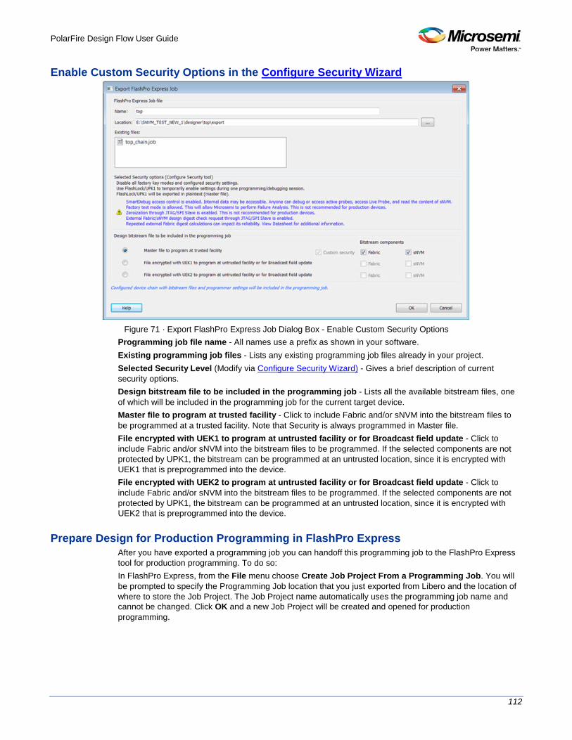
PolarFire Design Flow User Guide
112
Enable Custom Security Options in the Configure Security Wizard
Figure 71 · Export FlashPro Express Job Dialog Box - Enable Custom Security Options
Programming job file name - All names use a prefix as shown in your software. Existing programming job files - Lists any existing programming job files already in your project. Selected Security Level (Modify via Configure Security Wizard) - Gives a brief description of current security options. Design bitstream file to be included in the programming job - Lists all the available bitstream files, one of which will be included in the programming job for the current target device. Master file to program at trusted facility - Click to include Fabric and/or sNVM into the bitstream files to be programmed at a trusted facility. Note that Security is always programmed in Master file. File encrypted with UEK1 to program at untrusted facility or for Broadcast field update - Click to include Fabric and/or sNVM into the bitstream files to be programmed. If the selected components are not protected by UPK1, the bitstream can be programmed at an untrusted location, since it is encrypted with UEK1 that is preprogrammed into the device. File encrypted with UEK2 to program at untrusted facility or for Broadcast field update - Click to include Fabric and/or sNVM into the bitstream files to be programmed. If the selected components are not protected by UPK1, the bitstream can be programmed at an untrusted location, since it is encrypted with UEK2 that is preprogrammed into the device.
Prepare Design for Production Programming in FlashPro Express After you have exported a programming job you can handoff this programming job to the FlashPro Express tool for production programming. To do so: In FlashPro Express, from the File menu choose Create Job Project From a Programming Job. You will be prompted to specify the Programming Job location that you just exported from Libero and the location of where to store the Job Project. The Job Project name automatically uses the programming job name and cannot be changed. Click OK and a new Job Project will be created and opened for production programming.
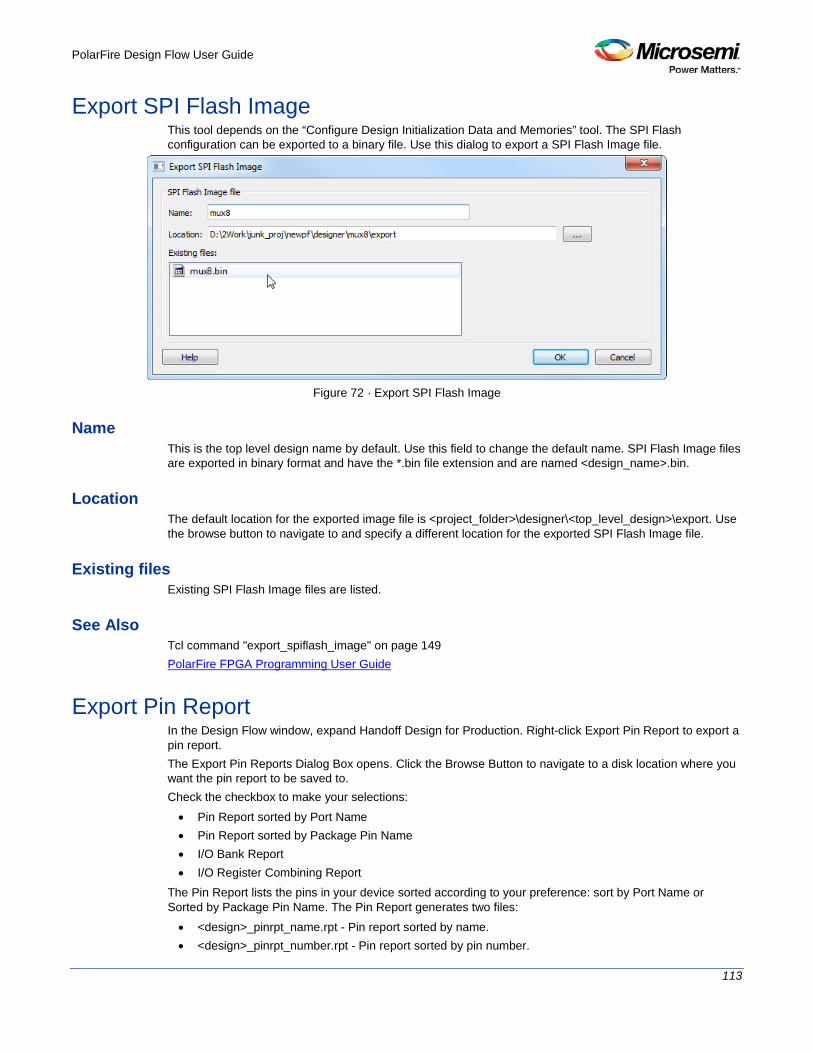
PolarFire Design Flow User Guide
113
Export SPI Flash Image This tool depends on the “Configure Design Initialization Data and Memories” tool. The SPI Flash configuration can be exported to a binary file. Use this dialog to export a SPI Flash Image file.
Figure 72 · Export SPI Flash Image
Name This is the top level design name by default. Use this field to change the default name. SPI Flash Image files are exported in binary format and have the *.bin file extension and are named <design_name>.bin.
Location The default location for the exported image file is <project_folder>\designer\<top_level_design>\export. Use the browse button to navigate to and specify a different location for the exported SPI Flash Image file.
Existing files Existing SPI Flash Image files are listed.
See Also Tcl command "export_spiflash_image" on page 149 PolarFire FPGA Programming User Guide
Export Pin Report In the Design Flow window, expand Handoff Design for Production. Right-click Export Pin Report to export a pin report. The Export Pin Reports Dialog Box opens. Click the Browse Button to navigate to a disk location where you want the pin report to be saved to. Check the checkbox to make your selections: • Pin Report sorted by Port Name • Pin Report sorted by Package Pin Name • I/O Bank Report • I/O Register Combining Report
The Pin Report lists the pins in your device sorted according to your preference: sort by Port Name or Sorted by Package Pin Name. The Pin Report generates two files: • <design>_pinrpt_name.rpt - Pin report sorted by name. • <design>_pinrpt_number.rpt - Pin report sorted by pin number.

PolarFire Design Flow User Guide
114
You must select at least one report. Export Pin Report generates a Bank Report by default; the filename is <design>-bankrpt.rpt. Export Pin Report also generates an I/O Register Combining Report listing the I/Os which have been combined into a Register for betting timing performance.
Figure 73 · Export Pin Report Dialog Box
Export BSDL File Double-click Export BSDL File (in the Libero SoC Design Flow window, Handoff Design for Production > Export BSDL File) to generate the BSDL File report to your Design Report. The BSDL file provides a standard file format for electronics testing using JTAG. It describes the boundary scan device package, pin description and boundary scan cell of the input and output pins. BSDL models are available as downloads for many Microsemi SoC devices. See the Microsemi website for more information on BSDL Models.

PolarFire Design Flow User Guide
115
Export SmartDebug Data (Libero SoC)
Export SmartDebug Data allows the export of SmartDebug Data from Libero to be handed off to the standalone SmartDebug environment. In the Libero SoC Design Flow window, expand Handoff Design for Debugging, right-click Export SmartDebug Data and click Export to open the Export SmartDebug Data dialog box. Specify the design debug data file (*.ddc)) to be exported. This file is also used as one of the ways to create a standalone SmartDebug project. See the following figure for an example.
Figure 74 · Export SmartDebug Data Dialog Box
Note: SmartDebug data can be exported without connecting the hardware. Design debug data file (*.ddc) Name The name of the design. Location

PolarFire Design Flow User Guide
116
The location of the exported debug file. By default, the *.ddc file is exported to the <project_location>/designer/<design>/export folder and has the *.ddc file extension. Existing Design Debug Data Files The existing *.ddc file, if any, in the export folder. SmartDebug data can be exported after you run Generate FPGA Array Data for the design in the Libero Design Flow. You can also directly export SmartDebug data after running Synthesize on the design. Other tools, such as Place and Route, Generate FPGA Array Data, and so forth) are implicitly run before the Export SmartDebug Data dialog box is displayed. Include design components A DDC file can contain the following components: • FPGA Array Probe Points – When checked, Libero SoC exports Live and Active probes information
(<design>_probe.db file) into the *.ddb container file. • FPGA Array Memory Blocks – When checked, Libero SoC exports information about FPGA
memories (<design>_sii_block.db) into the *.ddb container file: • names and addresses of the memory blocks instantiated by the design • data formats selected by the user in the design
• Security – This contains the security locks, keys, and security policy information needed for debug. This may be default or custom security (<design>.spm file). It is hidden if security is not supported for the device.
• JTAG Chain (device chain information configured using Programming Connectivity and Interface in Libero) – When checked, Libero SoC exports chain data including devices, their programming files if loaded, device properties, and so on (<design>.pro file). If JTAG chain is uchecked, the default JTAG chain with Libero design device only is added to the *.ddc file.
• Programmer Settings (<design>.pro file) – If Programmer Settings is unchecked, the default programmer settings are added to the *.ddc file.
• Device I/O States During Programming (<design>.ios file) – This setting is used by some SmartDebug features, for example, for programming sNVM . It is NOT used during device programming in SmartDebug; programming files used to program devices already have I/O states data.
In addition, you can include bitstream file information, which can be used for programming the device in standalone SmartDebug. Include Bitstream file to program at trusted facility • Bitstream components: Fabric • Bitstream components: sNVM
The default location of the DDC file is: <Libero_Project_directory>/designer/<design_name>/export. The DDC file can be exported to any user-specified location if the location has read and write permission.

PolarFire Design Flow User Guide
117
References
Project Manager - Cores Dialog Box (Advanced Download Mode)
This dialog box (shown below) enables you to download cores from a web repository into a Vault. A Vault is a local directory (either local to your machine or on the local network) that contains cores downloaded from one or more repositories. A repository is a location on the web that contains cores that can be included in your design. The Catalog displays all the cores in your Vault.
Figure 75 · Project Manager - Cores Dialog Box
Display only the latest version of a core is checked by default. This option, if checked, shows the latest versions of cores that are not in the Vault , and also filters out any duplicate cores that have the same Vendor, Library, and Name, with an earlier version number. If the checkbox is de-selected the dialog box displays all cores, including those already loaded into the Vault. The status column indicates if a core has already been loaded. Use the Filter to find any string that exists either in the core name or the Core Description. By default the filter contains a beginning and ending ‘*’, so if you type ‘controller’ you get all cores with controller in the core name (case insensitive search) or in the core description. The colored icons indicate the license status. Blank means that the core is not license protected in any way. Colored icons means that the core is license protected, with the following meanings: • Green Key - Fully licensed; supports the entire design flow. • Yellow Key - Has a limited or evaluation license only. Precompiled simulation libraries are provided,
enabling the core to be instantiated and simulated within the Microsemi Libero SoC Using the Evaluation version of the core it is possible to create and simulate the complete design in which the core is being included. The design is not synthesizable (RTL code is not provided). No license feature in the license.dat file is needed to run the core in evaluation mode. You can purchase a license to generate an obfuscated or RTL netlist.
• Yellow Key with Red Circle - License is protected; you are not licensed to use this core. Stop Downloads - Interrupts the download for any cores being added to your Vault.

PolarFire Design Flow User Guide
118
Add/Edit uPROM Client
Click Add or Edit to open a dialog to add/edit a uPROM client.
Figure 76 · Add uPROM Client Dialog
Client name
Enter the name of the uPROM client to be added
Content from File
Navigate to and specify a file, the content of which is to be used to fill the uPROM.
Content filled with 0s
Populates the uPROM with zero’s.
Start Address
Specifies the start address (in HEX) of the uPROM client. If there are multiple uPROM clients, the start address must not overlap. A warning message appears if there is address overlapping of uPROM clients. Valid start addresses range from 0 to CBFF (Hex).

PolarFire Design Flow User Guide
119
Number of 9-bit words
Specifies the number (in decimal) of 9-bit words to populate the uPROM. If the number of 9-bit words exceeds the memory size of the uPROM, an “out-of –bounds” warning message appears.
Use for initialization of RAMs
This option is disabled and unavailable from the Design and Memory Initialization tool.
Use Content for simulation
This option is disabled and unavailable from the Design and Memory Initialization tool.
Add sNVM Clients
Two different kinds of sNVM clients can be added: • Text Client • USK Client
Add Text client Use the dialog box to add text clients: • PlainText NonAuthenticated: 252 user bytes per page. • PlainText Authenticated: 236 user bytes per page. • CipherText Authenticated: 236 user bytes per page.
Figure 77 · Add Plain Text client

PolarFire Design Flow User Guide
120
Client name
Enter the name of the sNVM client to be added.
Content from File
Navigate to and specify a file, the content of which is to be used to fill the sNVM.
Content filled with 0s
Populates the sNVM with zero’s.
No Content
client is a placeholder and will not be programmed.
Start Page
Specifies the start page (in decimal) of the sNVM client. sNVM client address starts at page boundaries. If there are multiple sNVM clients, their start page cannot be the same. A warning message appears if there is address overlapping of sNVM clients. Valid start page range from 0 to 220 (Decimal).
Number of bytes
Specifies the total number (in decimal) of bytes to populate the sNVM. If the number of bytes exceeds the memory size of the sNVM, an “out-of –bounds” warning message appears. Valid ranges is from 1 to 47376
Use Content for simulation
Check if this client should be loaded for the simulation run.
Use as ROM
Check if this client should be used as read-only-memory (ROM).
Add USK client This client holds the USK. It is always 1 page (96 bytest) in size. There is no total byte entry for the USK client.

PolarFire Design Flow User Guide
121
Figure 78 · Add USK Client
Start Page
Start page can vary between 0 and 220.
USK Key
Enter a USK key (24 Hex characters). A random key can be generated by clicking the padlock icon to the right of this field.
Reprogram
Check if this client should be programmed.
Use Content for Simulation
Check if this client should be loaded for the simulation run.
Use as ROM
Check if this client should be used as read-only-memory (ROM).
Add/Edit SPI Flash
Click the Add button to add a SPI Bitstream client and the Edit button to modify an existing SPI Bitstream client.

PolarFire Design Flow User Guide
122
Figure 79 · Add/Edit SPI Client
Name Enter the name of the SPI Flash client to be added. Up to 32 alphanumeric characters are allowed. When editing an existing SPI Flash client, the client name cannot be changed.
Content Check one of the following to select the type of SPI Bitstream to be added. A total of 255 SPI clients can be added for IAP.
SPI Bitstream for IAP
Check this checkbox to add a SPI bitstream client for IAP.
SPI Bitstream for Recovery/Golden
Check this checkbox to add a client for Recovery/Golden. It is mandatory and only one is allowed. This option is disabled if one is already added. The existing one can be edited or deleted.
SPI Bitstream for Auto Update
This is available only when Auto Update is checked in the Configure SPI Flash tab. The SPI bitstream client is optional and only one is allowed. This option is disabled if one is already added. The existing one can be edited or deleted.
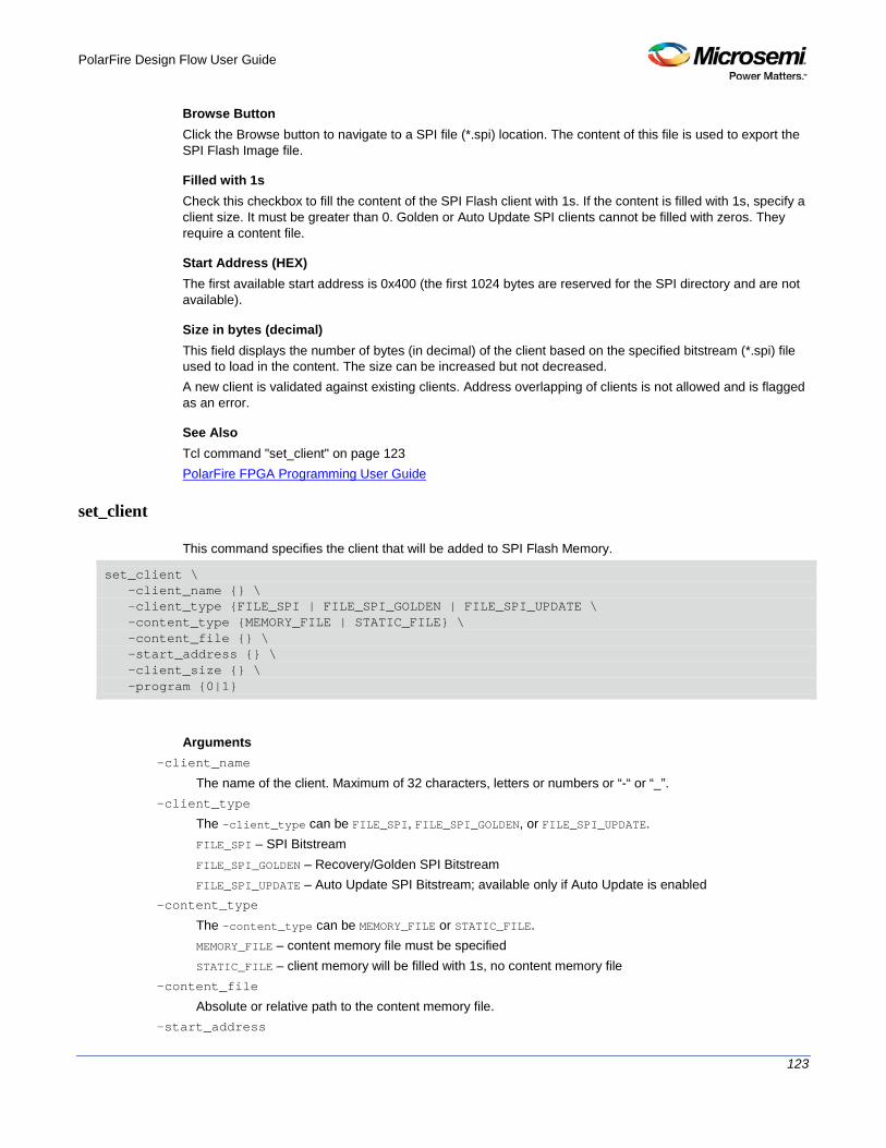
PolarFire Design Flow User Guide
123
Browse Button Click the Browse button to navigate to a SPI file (*.spi) location. The content of this file is used to export the SPI Flash Image file.
Filled with 1s Check this checkbox to fill the content of the SPI Flash client with 1s. If the content is filled with 1s, specify a client size. It must be greater than 0. Golden or Auto Update SPI clients cannot be filled with zeros. They require a content file.
Start Address (HEX) The first available start address is 0x400 (the first 1024 bytes are reserved for the SPI directory and are not available).
Size in bytes (decimal) This field displays the number of bytes (in decimal) of the client based on the specified bitstream (*.spi) file used to load in the content. The size can be increased but not decreased. A new client is validated against existing clients. Address overlapping of clients is not allowed and is flagged as an error.
See Also Tcl command "set_client" on page 123 PolarFire FPGA Programming User Guide
set_client
This command specifies the client that will be added to SPI Flash Memory.
set_client \ -client_name {} \ -client_type {FILE_SPI | FILE_SPI_GOLDEN | FILE_SPI_UPDATE \ -content_type {MEMORY_FILE | STATIC_FILE} \ -content_file {} \ -start_address {} \ -client_size {} \ -program {0|1}
Arguments -client_name
The name of the client. Maximum of 32 characters, letters or numbers or “-“ or “_”. -client_type
The -client_type can be FILE_SPI, FILE_SPI_GOLDEN, or FILE_SPI_UPDATE. FILE_SPI – SPI Bitstream FILE_SPI_GOLDEN – Recovery/Golden SPI Bitstream FILE_SPI_UPDATE – Auto Update SPI Bitstream; available only if Auto Update is enabled
-content_type
The -content_type can be MEMORY_FILE or STATIC_FILE. MEMORY_FILE – content memory file must be specified STATIC_FILE – client memory will be filled with 1s, no content memory file
-content_file
Absolute or relative path to the content memory file. -start_address

PolarFire Design Flow User Guide
124
The client start address. Note that some space is reserved for the SPI Flash Memory directory. -client_size
Client’s size in bytes. If a content file is specified, the size must be equal to or larger than the file size. -program {1}
Note: Only program | 1 is supported in this release.
Example The following example shows the set_client Tcl command. set_client \ -client_name {cl1} \ -client_type {FILE_SPI_GOLDEN} \ -content_type {MEMORY_FILE} \ -content_file {.\top_design_ver_3.spi} \ -start_address {1024} \ -client_size {9508667} \ -program {1}
configure_uprom
Tcl command; configures uPROM from the specified configuration file.
configure_uprom -cfg_file file
Arguments -cfg_file file
file is a valid configuration file to configure uPROM.
See Also
"Configure uPROM" on page 74
Sample uPROM Configuration File set_data_storage_client \
-client_name {client1_from_elsewhere} \
-number_of_words 37 \
-use_for_simulation {0} \
-content_type {MEMORY_FILE} \
-memory_file_format {Microsemi-Binary} \
-memory_file {C:/local_z_folder/work/memory files/sar_86586_uprom.mem} \
-base_address 1500
set_data_storage_client \
-client_name {large_1} \
-number_of_words 100 \
-use_for_simulation {0} \
-content_type {STATIC_FILL} \
-base_address 5000
configure_spiflash
This Tcl command configures SPI Flash Memory from the specified SPI Flash Memory configuration file.
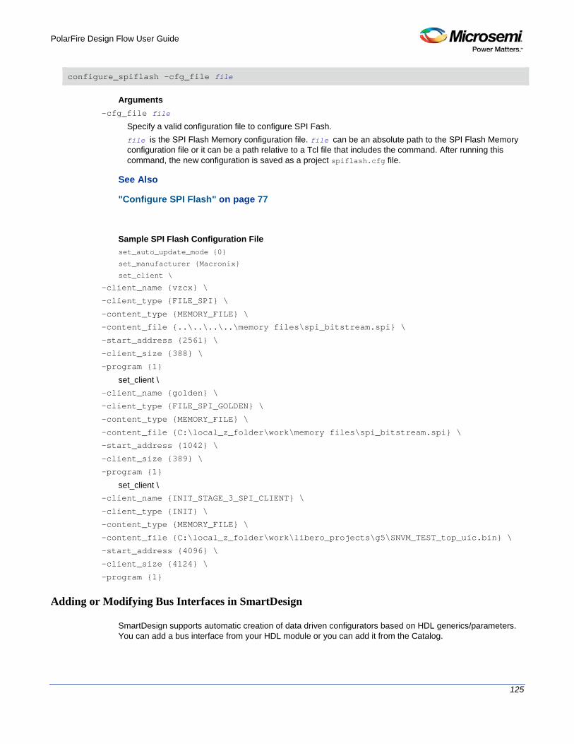
PolarFire Design Flow User Guide
125
configure_spiflash -cfg_file file
Arguments -cfg_file file
Specify a valid configuration file to configure SPI Fash. file is the SPI Flash Memory configuration file. file can be an absolute path to the SPI Flash Memory configuration file or it can be a path relative to a Tcl file that includes the command. After running this command, the new configuration is saved as a project spiflash.cfg file.
See Also
"Configure SPI Flash" on page 77
Sample SPI Flash Configuration File set_auto_update_mode {0}
set_manufacturer {Macronix}
set_client \
-client_name {vzcx} \
-client_type {FILE_SPI} \
-content_type {MEMORY_FILE} \
-content_file {..\..\..\..\memory files\spi_bitstream.spi} \
-start_address {2561} \
-client_size {388} \
-program {1}
set_client \ -client_name {golden} \
-client_type {FILE_SPI_GOLDEN} \
-content_type {MEMORY_FILE} \
-content_file {C:\local_z_folder\work\memory files\spi_bitstream.spi} \
-start_address {1042} \
-client_size {389} \
-program {1}
set_client \ -client_name {INIT_STAGE_3_SPI_CLIENT} \
-client_type {INIT} \
-content_type {MEMORY_FILE} \
-content_file {C:\local_z_folder\work\libero_projects\g5\SNVM_TEST_top_uic.bin} \
-start_address {4096} \
-client_size {4124} \
-program {1}
Adding or Modifying Bus Interfaces in SmartDesign
SmartDesign supports automatic creation of data driven configurators based on HDL generics/parameters. You can add a bus interface from your HDL module or you can add it from the Catalog.
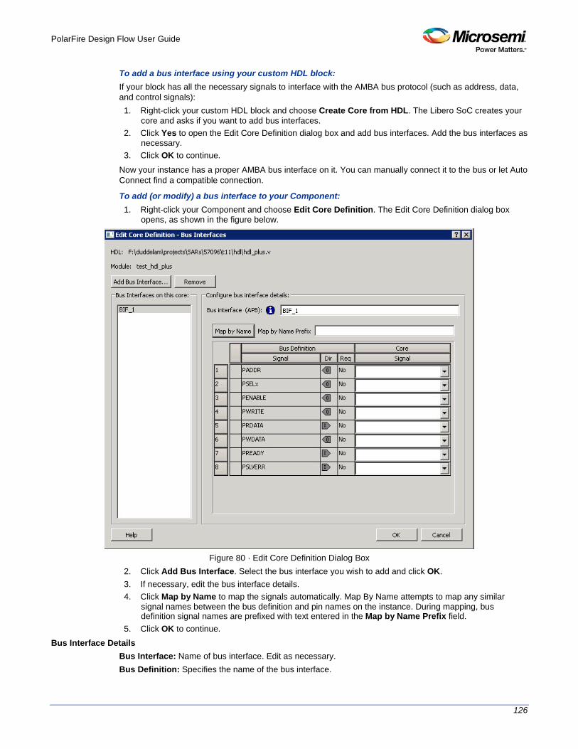
PolarFire Design Flow User Guide
126
To add a bus interface using your custom HDL block: If your block has all the necessary signals to interface with the AMBA bus protocol (such as address, data, and control signals):
1. Right-click your custom HDL block and choose Create Core from HDL. The Libero SoC creates your core and asks if you want to add bus interfaces.
2. Click Yes to open the Edit Core Definition dialog box and add bus interfaces. Add the bus interfaces as necessary.
3. Click OK to continue. Now your instance has a proper AMBA bus interface on it. You can manually connect it to the bus or let Auto Connect find a compatible connection.
To add (or modify) a bus interface to your Component: 1. Right-click your Component and choose Edit Core Definition. The Edit Core Definition dialog box
opens, as shown in the figure below.
Figure 80 · Edit Core Definition Dialog Box
2. Click Add Bus Interface. Select the bus interface you wish to add and click OK. 3. If necessary, edit the bus interface details. 4. Click Map by Name to map the signals automatically. Map By Name attempts to map any similar
signal names between the bus definition and pin names on the instance. During mapping, bus definition signal names are prefixed with text entered in the Map by Name Prefix field.
5. Click OK to continue. Bus Interface Details
Bus Interface: Name of bus interface. Edit as necessary. Bus Definition: Specifies the name of the bus interface.

PolarFire Design Flow User Guide
127
Role: Identifies the bus role (master or slave). Vendor: Identifies the vendor for the bus interface. Version: Identifies the version for the bus interface.
Configuration Parameters Certain bus definitions contain user configurable parameters. Parameter: Specifies the parameter name. Value: Specifies the value you define for the parameter. Consistent: Specifies whether a compatible bus interface must have the same value for this bus parameter. If the bus interface has a different value for any parameters that are marked with consistent set to yes, this bus interface will not be connectable.
Signal Map Definition The signal map of the bus interface specifies the pins on the instance that correspond to the bus definition signals. The bus definition signals are shown on the left, under the Bus Interface Definition. This information includes the name, direction and required properties of the signal. The pins for your instance are shown in the columns under the Component Instance. The signal element is a drop-down list of the pins that can be mapped for that definition signal. . If the Req field of the signal definition is Yes, you must map it to a pin on your instance for this bus interface to be considered legal. If it is No, you can leave it unmapped.
Catalog
In the Libero SoC, from the View menu choose Windows > Catalog. The Catalog displays a list of available cores, busses and macros (see image below).
Figure 81 · Libero SoC Catalog
From the Catalog, you can create a component from the list of available cores, add a processor or peripheral, add a bus interface to your SmartDesign component, instantiate simulation cores or add a macro (Arithmetic, Basic Block, etc.) to your SmartDesign component. Double-click a core to configure it and add it to your design. Configured cores are added to your list of Components/Modules in the Design Explorer. Click the Simulation Mode checkbox to instantiate simulation cores in your SmartDesign Testbench. Simulation cores are basic cores that are useful for stimulus, such as driving clocks, resets, and pulses.
Viewing Cores in the Catalog The font indicates the status of the core: • Plain text - In vault and available for use

PolarFire Design Flow User Guide
128
• Asterisk after name (*) - Newer version of the core (VLN) available for download • Italics - Core is available for download but not in your vault • Strikethrough - core is not valid for this version of Libero SoC
The colored icons indicate the license status. Blank means that the core is not license protected in any way. Colored icons mean that the core is license protected, with the following meanings:
Green Key - Fully licensed; supports the entire design flow. Yellow Key - Has a limited or evaluation license only. Precompiled simulation libraries are provided, enabling the core to be instantiated and simulated within Libero SoC. Using the Evaluation version of the core it is possible to create and simulate the complete design in which the core is being included. The design is not synthesizable (RTL code is not provided). No license feature in the license.dat file is needed to run the core in evaluation mode.You can purchase a license to generate an obfuscated or RTL netlist. Yellow Key with Red Circle - License is protected; you are not licensed to use this core.
Right-click any item in the Catalog and choose Show Details for a short summary of the core specifications. Choose Open Documentation for more information on the Core. Right-click and choose Configure Core to open the core generator. Click the Name column heading to sort the cores alphabetically. You can filter the cores according to the data in the Name and Description fields. Type the data into the filter field to view the cores that match the filter. You may find it helpful to set the Display setting in the Catalog Options to List cores alphabetically when using the filters to search for cores. By default the filter contains a beginning and ending ‘*’, so if you type ‘controller’ you get all cores with controller in the core name (case insensitive search) or in the core description. For example, to list all the Accumulator cores, in the filter field type: accu
Catalog Options Click the Options button (or the drop-down arrow next to it) to import a core, reload the Catalog, or modify the Catalog Options. You may want to import a core from a file when: • You do not have access to the internet and cannot download the core, or • A core is not complete and has not been posted to the web (you have an evaluation core)
Catalog Options Dialog Box
The Catalog Options dialog box (as shown below) enables you to customize your Catalog. You can add a repository, set the location of your vault, and change the View Settings for the Catalog. To display this dialog box, click the Catalog Options button .
Figure 82 · Catalog Display Options Dialog Box
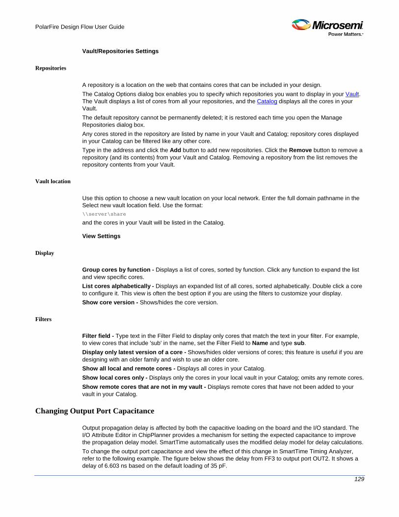
PolarFire Design Flow User Guide
129
Vault/Repositories Settings
Repositories
A repository is a location on the web that contains cores that can be included in your design. The Catalog Options dialog box enables you to specify which repositories you want to display in your Vault. The Vault displays a list of cores from all your repositories, and the Catalog displays all the cores in your Vault. The default repository cannot be permanently deleted; it is restored each time you open the Manage Repositories dialog box. Any cores stored in the repository are listed by name in your Vault and Catalog; repository cores displayed in your Catalog can be filtered like any other core. Type in the address and click the Add button to add new repositories. Click the Remove button to remove a repository (and its contents) from your Vault and Catalog. Removing a repository from the list removes the repository contents from your Vault.
Vault location
Use this option to choose a new vault location on your local network. Enter the full domain pathname in the Select new vault location field. Use the format: \\server\share
and the cores in your Vault will be listed in the Catalog.
View Settings
Display
Group cores by function - Displays a list of cores, sorted by function. Click any function to expand the list and view specific cores. List cores alphabetically - Displays an expanded list of all cores, sorted alphabetically. Double click a core to configure it. This view is often the best option if you are using the filters to customize your display. Show core version - Shows/hides the core version.
Filters
Filter field - Type text in the Filter Field to display only cores that match the text in your filter. For example, to view cores that include 'sub' in the name, set the Filter Field to Name and type sub. Display only latest version of a core - Shows/hides older versions of cores; this feature is useful if you are designing with an older family and wish to use an older core. Show all local and remote cores - Displays all cores in your Catalog. Show local cores only - Displays only the cores in your local vault in your Catalog; omits any remote cores. Show remote cores that are not in my vault - Displays remote cores that have not been added to your vault in your Catalog.
Changing Output Port Capacitance
Output propagation delay is affected by both the capacitive loading on the board and the I/O standard. The I/O Attribute Editor in ChipPlanner provides a mechanism for setting the expected capacitance to improve the propagation delay model. SmartTime automatically uses the modified delay model for delay calculations. To change the output port capacitance and view the effect of this change in SmartTime Timing Analyzer, refer to the following example. The figure below shows the delay from FF3 to output port OUT2. It shows a delay of 6.603 ns based on the default loading of 35 pF.

PolarFire Design Flow User Guide
130
Figure 83 · Maximum Delay Analysis View
If your board has output capacitance of 75pf on OUT2, you must perform the following steps to update the timing number:
1. Open the I/O Attribute Editor and change the output load to 75pf.
Figure 84 · I/O Attribute Editor View
2. Select File > Save. 3. Select File > Close. 4. Open the SmartTime Timing Analyzer.
You can see that the Clock to Output delay changed to 7.723 ns.
Core Manager
The Core Manager only lists cores that are in your current project. If any of the cores in your current project are not in your vault, you can use the Core Manager to download them all at once. For example, if you download a sample project and open it, you may not have all the cores in your local vault. In this instance you can use the Core Manager to view and download them with one click. Click Download All to add any missing cores to your vault. To add any individual core, click the green download button. To view the Core Manager, from the View menu choose Windows > Cores. The column headings in the Core Manager are: • Name - Core name. • Vendor - Source of the core. • Core Type - Core type. • Version - Version of the core used in your project; it may be a later version than you have in your
vault. If so, click Download All to download the latest version.

PolarFire Design Flow User Guide
131
configure_design_initialization_data
This Tcl command sets the parameter values needed for generating initialization data.
configure_design_initialization_data -second_stage_start_address {<valid_snvm_address>} \ -third_stage_start_address {<valid_address_for_third_stage_memory_type>} \ -third_stage_memory_type {<UPROM | SNVM | SPIFLASH_NONAUTH >}\ -third_stage_spi_clock_divider { 1 | 2 | 4 | 6} \ -init_timeout { <int_between_1_and_128_seconds>}
Arguments -second_stage_start_address
String parameter for the start address of the second stage initialization client. Specified as a 32-bit hexadecimal string. The first stage client is always placed in sNVM, so it must be a valid sNVM address aligned on a page boundary. There are 221 sNVM pages and each page is 256 bytes long, so the address will be between 0 and DC00. Notes: Although the actual size of each page is 256 bytes, only 252 bytes are available to the user. The first stage initialization client is always added to SNVM at 0xDC00 (page 220). So the valid addresses for the second stage initialization client are 0x0 (page 0) to 0xDB00 (page 219).
-third_stage_start_address
String parameter for the start address of the third stage initialization client. Specified as a 32-bit hexadecimal string, and must be one of the following: — valid sNVM address aligned on a page boundary — valid UPROM address aligned on a block boundary — valid SPIFLASH address
-third_stage_memory_type
The memory where the third stage initialization client will be placed. The value can be UPROM, SNVM, or SPIFLASH_NONAUTH. The default is UPROM. This parameter determines the valid value for parameter ‘third_stage_start_address’.
-third_stage_spi_clock_divider
The value can be 1, 2, 4, or 6. The default value is 1. -init_timeout
Timeout value in seconds. Initialization is aborted if it does not complete before timeout expires. The value can be between 1 and 128. The default value is 128.
Example configure_design_initialization_data -second_stage_start_address 200 \ -third_stage_start_address 400 \ -third_stage_memory_type UPROM \ -third_stage_spi_clock_divider 4 \ -init_timeout 120
See Also generate_design_initialization_data

PolarFire Design Flow User Guide
132
configure_snvm
Tcl command; configures sNVM from the specified configuration file.
configure_snvm -cfg_file file
Arguments -cfg_file file
file is a valid configuration file to configure sNVM.
See Also "Configure sNVM" on page 76
Sample sNVM Configuration File set_plain_text_client \
-client_name {pt_A} \
-number_of_bytes 64 \
-content_type {MEMORY_FILE} \
-content_file_format {Microsemi-Binary 8/16/32 bit} \
-content_file {C:/local_z_folder/work/memory files/binary8x16.mem} \
-start_page 0 \
-use_for_simulation 0 \
-reprogram 1 \
-use_as_rom 0
set_plain_text_client \
-client_name {pt_client} \
-number_of_bytes 64 \
-content_type {MEMORY_FILE} \
-content_file_format {Microsemi-Binary 8/16/32 bit} \
-content_file {C:/local_z_folder/work/memory files/binary32X16.mem} \
-start_page 2 \
-use_for_simulation 0 \
-reprogram 1 \
-use_as_rom 0
set_plain_text_client \
-client_name {pt_client_16bit} \
-number_of_bytes 32 \
-content_type {MEMORY_FILE} \
-content_file_format {Microsemi-Binary 8/16/32 bit} \
-content_file {C:/local_z_folder/work/memory files/binary16X16.mem} \
-start_page 1 \
-use_for_simulation 0 \
-reprogram 1 \
-use_as_rom 0
set_plain_text_client \
-client_name {INIT_STAGE_1_SNVM_CLIENT} \
-number_of_bytes 504 \

PolarFire Design Flow User Guide
133
-content_type {MEMORY_FILE} \
-content_file_format {Microsemi-Binary 8/16/32 bit} \
-content_file {designer\top\top_init_stage_1_snvm.mem} \
-start_page 219 \
-use_for_simulation 0 \
-reprogram 1 \
-use_as_rom 0
set_plain_text_client \
-client_name {pt_B} \
-number_of_bytes 1 \
-content_type {STATIC_FILL} \
-content_file_format {Microsemi-Binary 8/16/32 bit} \
-content_file {} \
-start_page 3 \
-use_for_simulation 0 \
-reprogram 1 \
-use_as_rom 0
Importing Source Files – Copying Files Locally
Designer in Libero SoC cannot import files from outside your project without copying them to your local project folder. You may import source files from other locations, but they are always copied to your local folder. Designer in Libero SoC always audits the local file after you import; it does not audit the original file. When the Project Manager asks you if you want to copy files "locally", it means 'copy the files to your local project folder'. If you do not wish to copy the files to your local project folder, you cannot import them. Your local project folder contains files related to your Libero SoC project. Files copied to your local folders are copied directly into their relevant directory: netlists are copied to the synthesis folder; source files are copied to hdl folder and constraint files to constraint folder, etc. The files are also added to the Libero SoC project; they appear in the Files tab.
Create Clock Constraint Dialog Box
Use this dialog box to enter a clock constraint setting. It displays a typical clock waveform with its associated clock information. You can enter or modify this information, and save the final settings as long as the constraint information is consistent and defines the clock waveform completely. The tool displays errors and warnings if information is missing or incorrect. To open the Create Clock Constraint dialog box (shown below) from the SmartTime Constraints Editor, choose Constraints > Clock.

PolarFire Design Flow User Guide
134
Figure 85 · Create Clock Constraint Dialog Box
Clock Source Enables you to choose a pin from your design to use as the clock source. The drop-down list is populated with all explicit clocks. You can also select the Browse button to access all potential clocks. The Browse button displays the Select Source Pins for Clock Constraint Dialog Box.
Clock Name Specifies the name of the clock constraint. This field is required for virtual clocks when no clock source is provided.
T(zero) Label Instant zero used as a common starting time to all clock constraints.
Period When you edit the period, the tool automatically updates the frequency value. The period must be a positive real number. Accuracy is up to 3 decimal places.
Frequency When you edit the frequency, the tool automatically updates the period value. The frequency must be a positive real number. Accuracy is up to 3 decimal places.
Offset (Starting Edge Selector) Enables you to switch between rising and falling edges and updates the clock waveform. If the current setting of starting edge is rising, you can change the starting edge from rising to falling. If the current setting of starting edge is falling, you can change the starting edge from falling to rising.
Duty Cycle This number specifies the percentage of the overall period that the clock pulse is high. The duty cycle must be a positive real number. Accuracy is up to 4 decimal places. Default value is 50%.
Offset The offset must be a positive real number. Accuracy is up to 2 decimal places. Default value is 0.
Comment Enables you to save a single line of text that describes the clock constraints purpose.

PolarFire Design Flow User Guide
135
See Also Specifying Clock Constraints
Select Source Pins for Clock Constraint Dialog Box
Use this dialog box to find and choose the clock source from the list of available pins. To open the Select Source Pins for the Clock Constraint dialog box (shown below) from the SmartTime Constraints Editor, click the Browse button to the right of the Clock source field in the Create Clock Constraint dialog box.
Figure 86 · Select Source Pins for Clock Constraint Dialog Box
Available Pins Displays all available pins.
Filter Available Pins Explicit clock pins for the design is the default value. To identify any other pins in the design as clock pins, right-click the Pin Type pull-down menu and select one of the following: • Explicit clocks • Potential clocks • Input ports • All Pins • All Nets • Pins on clock network • Nets in clock network

PolarFire Design Flow User Guide
136
You can also use the Filter to filter the clock source pin name in the displayed list.
See Also Specifying clock constraints
Specifying Clock Constraints
Specifying clock constraints is the most effective way to constrain and verify the timing behavior of a sequential design. Use clock constraints to meet your performance goals.
To specify a clock constraint: 1. Add the constraint in the editable constraints grid or open the Create Clock Constraint dialog box using
one of the following methods:
• Click the icon in the Constraints Editor. • Right-click the Clock in the Constraint Browser and choose Add Clock Constraint. • Double-click Clock in the Constraint Browser.
The Create Clock Constraint dialog box appears (as shown below).
Figure 87 · Create Clock Constraint Dialog Box
2. Select the pin to use as the clock source. You can click the Browse button to display the Select Source Pins for Clock Constraint Dialog Box (as shown below).
Note: Do not select a source pin when you specify a virtual clock. Virtual clocks can be used to define a clock outside the FPGA that is used to synchronize I/Os.
Use the Choose the Clock Source Pin dialog box to display a list of source pins from which you can choose. By default, it displays the explicit clock sources of the design. To choose other pins in the design as clock source pins, select Filter available objects - Pin Type as Explicit clocks, Potential clocks, All Ports, All Pins, All Nets, Pins on clock network, or Nets in clock network. To display a subset of the displayed clock source pins, you can create and apply a filter. Multiple source pins can be specified for the same clock when a single clock is entering the FPGA using multiple inputs with different delays. Click OK to save these dialog box settings.
3. Specify the Period in nanoseconds (ns) or Frequency in megahertz (MHz). 4. Modify the Clock Name. The name of the first clock source is provided as default. 5. Modify the Duty cycle, if needed. 6. Modify the Offset of the clock, if needed. 7. Modify the first edge direction of the clock, if needed. 8. Click OK. The new constraint appears in the Constraints List.

PolarFire Design Flow User Guide
137
Note: When you choose File > Save, the Timing Constraints Editor saves the newly created constraint in the database.
Figure 88 · Timing Constraint View
Create Generated Clock Constraint Dialog Box
Use this dialog box to specify generated clock constraint settings. It displays a relationship between the clock source and its reference clock. You can enter or modify this information, and save the final settings as long as the constraint information is consistent. The tool displays errors and warnings if the information is missing or incorrect. To open the Create Generated Clock Constraint dialog box (shown below) from the SmartTime Constraints Editor, choose Constraints > Generated Clock.

PolarFire Design Flow User Guide
138
Figure 89 · Create Generated Clock Constraint
Clock Pin Enables you to choose a pin from your design to use as a generated clock source. The drop-down list is populated with all unconstrained explicit clocks. You can also select the Browse button to access all potential clocks and pins from the clock network. The Browse button displays the Select Generated Clock Source dialog box.
Reference Pin Enables you to choose a pin from your design to use as a generated reference pin.
Generated Clock Name Specifies the name of the clock constraint. This field is required for virtual clocks when no clock source is provided.
Generated Frequency The generated frequency is a factor of reference frequency defined with a multiplication element and/or a division element.
Generated Waveform The generated waveform could be either the same as or inverted w.r.t. the reference waveform.
Comment Enables you to save a single line of text that describes the generated clock constraints purpose.

PolarFire Design Flow User Guide
139
See Also create_generated_clock (SDC) Specifying Generated Clock Constraints Select Generated Clock Source
Select Generated Clock Source Dialog Box
Use this dialog box to find and choose the generated clock source from the list of available pins. To open the Select Generated Clock Source dialog box (shown below) from the Timing Constraints Editor, open the Create Generated Clock Constraint dialog box and click the Browse button for the Clock Pin.
Figure 90 · Select Generated Clock Source Dialog Box
Filter Available Pins
Explicit clock pins for the design is the default value. To identify any other pins in the design as the generated clock source pins, from the Pin Type pull-down list, select Explicit clocks, Potential clocks, All Ports, All Pins, All Nets, Pins on clock network, or Nets in clock network. You can also use the Filter to filter the generated clock source pin name in the displayed list.
Specifying Generated Clock Constraints
Specifying a generated clock constraint enables you to define an internally generated clock for your design and verify its timing behavior. Use generated clock constraints and clock constraints to meet your performance goals.
To specify a generated clock constraint: 1. Open the Create Generated Clock Constraint dialog box using one of the following methods:
• Click the icon. • Right-click the Generated Clock in the Constraint Browser and choose Add Generated Clock.

PolarFire Design Flow User Guide
140
• Double-click the Generated Clock Constraints grid. The Create Generated Clock Constraint dialog box appears (as shown below).
Figure 91 · Create Generated Clock Constraint
2. Select a Clock Pin to use as the generated clock source. To display a list of available generated clock source pins, click the Browse button. The Select Generated Clock Source dialog box appears (as shown below).

PolarFire Design Flow User Guide
141
Figure 92 · Select Generated Clock Source Dialog Box
3. Modify the Clock Name if necessary. 4. Click OK to save these dialog box settings. 5. Specify a Clock Reference. To display a list of available clock reference pins, click the Browse
button. The Select Generated Clock Reference dialog box appears. 5. Click OK to save the dialog box settings. 6. Specify the values to calculate the generated frequency: a multiplication factor and/or a division factor
(both positive integers). 7. Specify the first edge of the generated waveform either same as or inverted with respect to the
reference waveform. 8. Click OK. The new constraint appears in the Constraints List.
Tip: From the File menu, choose Save to save the newly created constraint in the database.
Select Generated Clock Reference Dialog Box
Use this dialog box to find and choose the generated clock reference pin from the list of available pins. To open the Select Generated Clock Reference dialog box (shown below) from the SmartTime Constraints Editor, open the Create Generated Clock Constraint Dialog Box dialog box and click the Browse button for the Clock Reference.
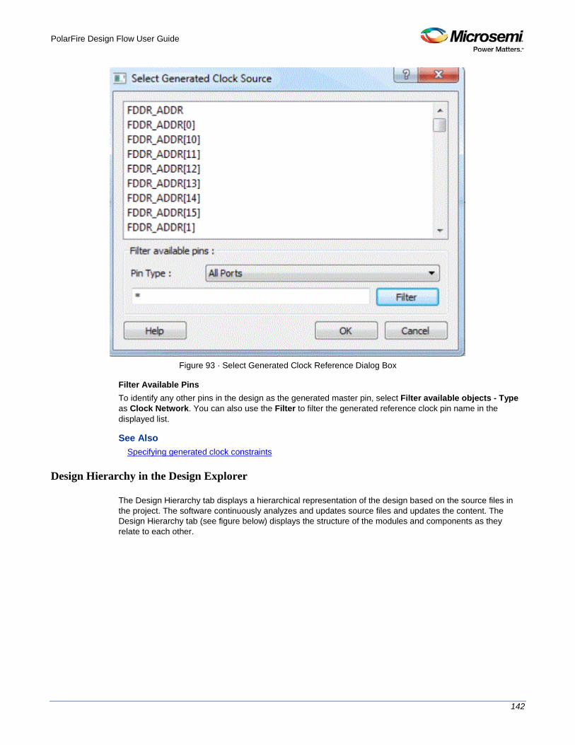
PolarFire Design Flow User Guide
142
Figure 93 · Select Generated Clock Reference Dialog Box
Filter Available Pins To identify any other pins in the design as the generated master pin, select Filter available objects - Type as Clock Network. You can also use the Filter to filter the generated reference clock pin name in the displayed list.
See Also Specifying generated clock constraints
Design Hierarchy in the Design Explorer
The Design Hierarchy tab displays a hierarchical representation of the design based on the source files in the project. The software continuously analyzes and updates source files and updates the content. The Design Hierarchy tab (see figure below) displays the structure of the modules and components as they relate to each other.

PolarFire Design Flow User Guide
143
Figure 94 · Design Hierarchy
You can change the display mode of the Design Hierarchy by selecting Components or Modules from the Show drop-down list. The components view displays the entire design hierarchy; the modules view displays only schematic and HDL modules. You can build the Design Hierarchy and Simulation Hierarchy by clicking the Build button. Note: The Build button appears only if Enable On Demand Build Design Hierarchy has been enabled in Project Settings. This option is enabled by default for PolarFire devices.
A yellow icon indicates that the Design Hierarchy is out of date (invalidated). Any change to the design sources/stimuli invalidates the Design Hierarchy. Click the Build button to rebuild the Design hierarchy. The file name (the file that defines the block) appears next to the block name in parentheses. To view the location of a component, right-click and choose Properties. The Properties dialog box displays the pathname, created date, and last modified date. All integrated source editors are linked with the SoC software. If a source is modified and the modification changes the hierarchy of the design, the Design Hierarchy automatically updates to reflect the change. If you want to update the Design Hierarchy, from the View menu, choose Refresh Design Hierarchy.
To open a component: Double-click a component in the Design Hierarchy to open it. Depending on the block type and design state, several possible options are available from the right-click menu. You can instantiate a component from the Design Hierarchy to the SmartDesign Canvas. See the SmartDesign User Guide for more information. Icons in the Hierarchy indicate the type of component and the state, as shown in the table below.
Table 4 · Design Hierarchy Icons
Icon Description
SmartDesign component
SmartDesign component with HDL netlist not generated
IP core was instantiated into SmartDesign but the HDL netlist has not been generated
Core
Error during core validation

PolarFire Design Flow User Guide
144
Icon Description
Updated core available for download
HDL netlist
Digest File
Users can verify which bitstream file was programmed onto their devices by running the VERIFY or VERIFY_DIGEST actions on each device that was programmed. This is a costly and time-consuming process. To speed up the verification process, digests are printed during bitstream generation and bitstream programming. These digests can be compared to verify that all of the devices were programmed with the correct bitstream file. The bitstream file is divided into three major component sections: FPGA fabric, eNVM, and Security. A valid bitstream will contain a combination of any of the three primary bitstream components.
Use Case When a customer creates a design in Libero and then exports the STAPL file (for FlashPro) or programming job (for FlashPro Express), the digest of each of the primary components is printed in the Libero log window and saved in a digest file under the export folder. The digest file is a text file containing the bitstream component name with its corresponding digest. The name of the digest file will match the name of the STAPL/programming job exported, and will be appended with a “.digest” extension. The customer then sends the STAPL/programming job to a production programming house. Now, when the devices are programmed, the digest of each of the primary components is printed in the log window. The production programming house saves the log files and sends the devices along with log files back to the customer. The customer can then verify that the correct design was programmed on the device by matching the digests in the log file with that in the *.digest file under the Libero export folder.
Example Using STAPL File
If a STAPL file is exported, the digests will be printed in the log window, as shown in the example below. Libero log: Opened 'D:/flashpro_files/m2s005_digest1/designer/a1_MSS/a1_MSS_fp/a1_MSS.pro'
The 'open_project' command succeeded.
PDB file
'D:\flashpro_files\m2s005_digest1\designer\a1_MSS\4a8552f8-57ee-4baa-97ee-2baa57ee2baa.pdb' has
been loaded successfully.
DESIGN : a1_MSS; CHECKSUM : DE15; PDB_VERSION : 1.9
The 'load_programming_data' command succeeded.
Sucessfully exported STAPL file:
'D:\flashpro_files\m2s005_digest1\designer\a1_MSS\export\a1_MSS.stp'; file programs Fabric
and eNVM. Fabric component digest:
276fbefb0a18cc0de1d45efc84589745ee02fc2adbcc1259fbeb674094754014
eNVM component digest:
6b2c2353e25c5982643c32640ac16c581874c8950300135622c126ee22d8b1de
Finished: Thu Jan 22 12:37:32 2015 (Elapsed time 00:00:06)
The 'export_single_stapl' command succeeded.
The 'set_programming_file' command succeeded.
Project saved.

PolarFire Design Flow User Guide
145
The 'save_project' command succeeded.
Project closed.
The export folder will contain the exported STAPL file along with digest file. In this example, there will be two files, “a1_MSS.stp” and “a1_MSS_stp.digest”. The content of the a1_MSS_stp.digest file is shown below: Fabric component digest: 276fbefb0a18cc0de1d45efc84589745ee02fc2adbcc1259fbeb674094754014
eNVM component digest: 6b2c2353e25c5982643c32640ac16c581874c8950300135622c126ee22d8b1de
When the device is programmed in the production programming house by loading the STAPL file in FlashPro, the log will be as follows: programmer '73207' : Scan Chain...
Warning: programmer '73207' : Vpump has been selected on programmer AND an externally provided Vpump has also been detected. Using externally provided Vpump voltage source.
programmer '73207' : Check Chain...
programmer '73207' : Scan and Check Chain PASSED.
programmer '73207' : device 'M2S/M2GL005(S)' : Executing action PROGRAM
programmer '73207' : device 'M2S/M2GL005(S)' : Family: SmartFusion2
programmer '73207' : device 'M2S/M2GL005(S)' : Product: M2S005
programmer '73207' : device 'M2S/M2GL005(S)' : EXPORT ISC_ENABLE_RESULT[32] = 007c6b44
programmer '73207' : device 'M2S/M2GL005(S)' : EXPORT CRCERR: [1] = 0
programmer '73207' : device 'M2S/M2GL005(S)' : EXPORT EDCERR: [1] = 0
programmer '73207' : device 'M2S/M2GL005(S)' : TEMPGRADE: ROOM
programmer '73207' : device 'M2S/M2GL005(S)' : EXPORT VPPRANGE: [3] = 2
programmer '73207' : device 'M2S/M2GL005(S)' : VPPRANGE: HIGH
programmer '73207' : device 'M2S/M2GL005(S)' : EXPORT TEMP: [8] = 6b
programmer '73207' : device 'M2S/M2GL005(S)' : EXPORT VPP: [8] = 7c
programmer '73207' : device 'M2S/M2GL005(S)' : Programming FPGA Array and eNVM...
programmer '73207' : device 'M2S/M2GL005(S)' : EXPORT Fabric component digest[256] =
276fbefb0a18cc0de1d45efc84589745ee02fc2adbcc1259fbeb674094754014
programmer '73207' : device 'M2S/M2GL005(S)' : EXPORT eNVM component digest[256] =
6b2c2353e25c5982643c32640ac16c581874c8950300135622c126ee22d8b1de
programmer '73207' : device 'M2S/M2GL005(S)' : ===================================================================================
programmer '73207' : device 'M2S/M2GL005(S)' : EXPORT DSN[128] = c6e99c2d1a992f13cf8231c4be847acb
programmer '73207' : device 'M2S/M2GL005(S)' : ===================================================================================
programmer '73207' : device 'M2S/M2GL005(S)' : Finished: Thu Jan 22 17:57:37 2015 (Elapsed time 00:00:19)
programmer '73207' : device 'M2S/M2GL005(S)' : Executing action PROGRAM PASSED.
programmer '73207' : Chain programming PASSED.
Chain Programming Finished: Thu Jan 22 17:57:37 2015 (Elapsed time 00:00:19)
o - o - o - o - o - o
The log file is saved and sent back to the customer, who can verify that the device was programmed with the correct design by comparing the digests in the log file to the contents of the a1_MSS_stp.digest file.
Example Using Programming Job
If a programming job is exported, the digests will be printed in the log window, as shown in the example below. Libero log: Software Version: 11.5.1.5
Opened 'D:/flashpro_files/m2s005_digest1/designer/a1_MSS/a1_MSS_fp/a1_MSS.pro'
The 'open_project' command succeeded.
PDB file

PolarFire Design Flow User Guide
146
'D:\flashpro_files\m2s005_digest1\designer\a1_MSS\83ce6816-1e56-496b-9e56-d96b1e56d96b.pdb' has
been loaded successfully.
DESIGN : a1_MSS; CHECKSUM : DE15; PDB_VERSION : 1.9
The 'load_programming_data' command succeeded.
Sucessfully exported STAPL file:
'D:\flashpro_files\m2s005_digest1\designer\a1_MSS\export\a1_MSS_M2S005.stp'; file programs
Fabric and eNVM. Fabric component digest:
276fbefb0a18cc0de1d45efc84589745ee02fc2adbcc1259fbeb674094754014
eNVM component digest:
6b2c2353e25c5982643c32640ac16c581874c8950300135622c126ee22d8b1de
Finished: Wed Jan 28 16:48:56 2015 (Elapsed time 00:00:06)
The 'export_single_stapl' command succeeded.
The 'set_programming_file' command succeeded.
Project saved.
The 'save_project' command succeeded.
Project closed.
The export folder will contain the exported programming job along with digest file. In this example, there will be two files, “a1_MSS.job” and “a1_MSS_job.digest” . The content of the a1_MSS_job.digest file is shown below: Fabric component digest: 276fbefb0a18cc0de1d45efc84589745ee02fc2adbcc1259fbeb674094754014
eNVM component digest: 6b2c2353e25c5982643c32640ac16c581874c8950300135622c126ee22d8b1de
When the device is programmed in the production programming house by loading the programming job in FlashPro Express, the log will be as follows: programmer '73207' : Scan Chain...
Warning: programmer '73207' : Vpump has been selected on programmer AND an externally provided Vpump has also been detected. Using externally provided Vpump voltage source.
programmer '73207' : Check Chain...
programmer '73207' : Scan and Check Chain PASSED.
programmer '73207' : device 'M2S/M2GL005(S)' : Executing action PROGRAM
programmer '73207' : device 'M2S/M2GL005(S)' : Family: SmartFusion2
programmer '73207' : device 'M2S/M2GL005(S)' : Product: M2S005
programmer '73207' : device 'M2S/M2GL005(S)' : EXPORT ISC_ENABLE_RESULT[32] = 007c6b44
programmer '73207' : device 'M2S/M2GL005(S)' : EXPORT CRCERR: [1] = 0
programmer '73207' : device 'M2S/M2GL005(S)' : EXPORT EDCERR: [1] = 0
programmer '73207' : device 'M2S/M2GL005(S)' : TEMPGRADE: ROOM
programmer '73207' : device 'M2S/M2GL005(S)' : EXPORT VPPRANGE: [3] = 2
programmer '73207' : device 'M2S/M2GL005(S)' : VPPRANGE: HIGH
programmer '73207' : device 'M2S/M2GL005(S)' : EXPORT TEMP: [8] = 6b
programmer '73207' : device 'M2S/M2GL005(S)' : EXPORT VPP: [8] = 7c
programmer '73207' : device 'M2S/M2GL005(S)' : Programming FPGA Array and eNVM...
programmer '73207' : device 'M2S/M2GL005(S)' : EXPORT Fabric component digest[256] =
276fbefb0a18cc0de1d45efc84589745ee02fc2adbcc1259fbeb674094754014
programmer '73207' : device 'M2S/M2GL005(S)' : EXPORT eNVM component digest[256] =
6b2c2353e25c5982643c32640ac16c581874c8950300135622c126ee22d8b1de
programmer '73207' : device 'M2S/M2GL005(S)' : ===================================================================================
programmer '73207' : device 'M2S/M2GL005(S)' : EXPORT DSN[128] = c6e99c2d1a992f13cf8231c4be847acb
programmer '73207' : device 'M2S/M2GL005(S)' : ===================================================================================

PolarFire Design Flow User Guide
147
programmer '73207' : device 'M2S/M2GL005(S)' : Finished: Thu Jan 22 17:57:37 2015 (Elapsed time 00:00:19)
programmer '73207' : device 'M2S/M2GL005(S)' : Executing action PROGRAM PASSED.
programmer '73207' : Chain programming PASSED.
Chain Programming Finished: Thu Jan 22 17:57:37 2015 (Elapsed time 00:00:19)
o - o - o - o - o - o
The log file is saved and sent back to the customer, who can verify that the device was programmed with the correct design by comparing the digests in the log file above to the contents of the a1_MSS_job.digest file.
See Also Export Bitstream
Design Rules Check
The Design Rules Check runs automatically when you generate your SmartDesign; the results appear in the
Reports tab. You can also initiate a Design Rules Check by clicking on the button of the SmartDesign Canvas tab menu. To view the results, from the Design menu, choose Reports. • Status displays an icon to indicate if the message is an error or a warning (as shown in the figure
below). Error messages are shown with a small red sign and warning messages with a yellow exclamation point.
• Message identifies the specific error/warning (see list below); click any message to see where it appears on the Canvas
• Details provides information related to the Message
Figure 95 · Design Rules Check Results
Message Types: Unused Instance - You must remove this instance or connect at least one output pin to the rest of the design. Out-of-date Instance - You must update the instance to reflect a change in the component referenced by this instance.

PolarFire Design Flow User Guide
148
Undriven Pin - To correct the error you must connect the pin to a driver or change the state, i.e. tie low (GND) or tie high (VCC). Floating Driver - You can mark the pin unused if it is not going to be used in the current design. Pins marked unused are ignored by the Design Rules Check. Unconnected Bus Interface - You must connect this bus interface to a compatible port because it is required connection. Required Bus Interface Connection – You must connect this bus interface before you can generate the design. These are typically silicon connection rules. Exceeded Allowable Instances for Core – Some IP cores can only be instantiated a certain number of times for legal design because of silicon limitations. You must remove the extra instances. Incompatible Family Configuration – The instance is not configured to work with this project’s Family setting. Either it is not supported by this family or you need to re-instantiate the core. Incompatible Die Configuration – The instance is not configured to work with this project’s Die setting. Either it is not supported or you need to reconfigure the Die configuration. No RTL License, No Obfuscated License, No Evaluation License – You do not have the proper license to generate this core. Contact Microsemi SoC to obtain the necessary license. No Top level Ports - There are no ports on the top level. To auto-connect top-level ports, right-click the Canvas and choose Auto-connect Self-Instantiation - A component cannot instantiate itself-This is reported only in the Log/Message Window.
Editable Constraints Grid
The Constraints Editor enables you to add, edit and delete.
Figure 96 · Constraints Editor
To add a new constraint: 1. Select a constraint type from the constraint browser. 2. Enter the constraint values in the first row and click the green check mark to apply your changes. To
cancel the changes press the red cancel mark. 3. The new constraint is added to the Constraint List. The green syntax flag indicates that the constraint
was successfully checked.
To edit a constraint: 1. Select a constraint type from the constraint browser. 2. Select the constraint, edit the values and click the green check mark to apply your changes. To cancel
the changes press the red cancel mark. The green syntax flag indicates that the constraint was successfully checked.
To delete a constraint: 1. Select a constraint type from the constraint browser.

PolarFire Design Flow User Guide
149
2. Right-click the constraint you want to delete and choose Delete Constraint.
export_spiflash_image
This Tcl command exports a SPI Flash image file to a specified directory.
export_spiflash_image -file_name {name of file} -export_dir {absolute path to folder location}
Arguments -file_name name of file
The name of the image file. -export_dir absolute path to folder location
Folder/directory location.
See Also
"Export SPI Flash Image" on page 113
extended_run_lib
Note: This is not a Tcl command; it is a shell script that can be run from the command line. The extended_run_lib Tcl script enables you to run the multiple pass layout in batch mode from a command line.
$ACTEL_SW_DIR/bin/libero script:$ACTEL_SW_DIR/scripts/extended_run_lib.tcl logfile:extended_run.log “script_args:-root path/designer/module_name [-n numPasses] [-starting_seed_index numIndex] [-compare_criteria value] [-c clockName] [-analysis value] [-slack_criteria value] [-stop_on_success] [-timing_driven|-standard] [-power_driven value] [-placer_high_effort value]”
Note: • There is no option to save the design files from all the passes. Only the (Timing or Power) result
reports from all the passes are saved.
Arguments -root path/designer/module_name
The path to the root module located under the designer directory of the Libero project. [-n numPasses]
Sets the number of passes to run. The default number of passes is 5. [-starting_seed_index numIndex]
Indicates the specific index into the array of random seeds which is to be the starting point for the passes. Value may range from 1 to 100. If not specified, the default behavior is to continue from the last seed index that was used.
[-compare_criteria value]
Sets the criteria for comparing results between passes. The default value is set to frequency when the –c option is given or timing constraints are absent. Otherwise, the default value is set to violations.
Value Description
frequency Use clock frequency as criteria for comparing the results between passes. This option can be used in conjunction with the -c option (described below).
violations Use timing violations as criteria for comparing the results between passes. This option can be used in

PolarFire Design Flow User Guide
150
Value Description
conjunction with the -analysis, -slack_criteria and -stop_on_success options (described below).
power Use total power as criteria for comparing the results between passes, where lowest total power is the goal.
[-c clockName]
Applies only when the clock frequency comparison criteria is used. Specifies the particular clock that is to be examined. If no clock is specified, then the slowest clock frequency in the design in a given pass is used. The clock name should match with one of the Clock Domains in the Summary section of the Timing report.
[-analysis value]
Applies only when the timing violations comparison criteria is used. Specifies the type of timing violations (the slack) to examine. The following table shows the acceptable values for this argument:
Value Description
max Examines timing violations (slack) obtained from maximum delay analysis. This is the default.
min Examines timing violations (slack) obtained from minimum delay analysis.
[-slack_criteria value]
Applies only when the timing violations comparison criteria is used. Specifies how to evaluate the timing violations (slack). The type of timing violations (slack) is determined by the -analysis option. The following table shows the acceptable values for this argument:
Value Description
worst Sets the timing violations criteria to Worst slack. For each pass obtains the most amount of negative slack (or least amount of positive slack if all constraints are met) from the timing violations report. The largest value out of all passes will determine the best pass. This is the default.
tns Sets the timing violations criteria to Total Negative Slack (tns). For each pass it obtains the sum of negative slack values from the first 100 paths from the timing violations report. The largest value out of all passes determines the best pass. If no negative slacks exist for a pass, then the worst slack is used to evaluate that pass.
[-stop_on_success]
Applies only when the timing violations comparison criteria is used. The type of timing violations (slack) is determined by the -analysis option. Stops running the remaining passes if all timing constraints have been met (when there are no negative slacks reported in the timing violations report).
[-timing_driven|-standard]
Sets layout mode to timing driven or standard (non-timing driven). The default is -timing_driven or the mode used in the previous layout command.
[-power_driven value]
Enables or disables power-driven layout. The default is off or the mode used in the previous layout command. The following table shows the acceptable values for this argument:
Value Description
off Does not run power-driven layout.
on Enables power-driven layout.

PolarFire Design Flow User Guide
151
[-placer_high_effort value]
Sets placer effort level. The default is off or the mode used in the previous layout command. The following table shows the acceptable values for this argument:
Value Description
off Runs layout in regular effort.
on Activates high effort layout mode.
Return A non-zero value will be returned on error.
Supported Families PolarFire
Exceptions None Place and Route - PolarFire Multiple Pass Layout - PolarFire
Files Tab and File Types
The Files tab displays all the files associated with your project, listed in the directories in which they appear. Right-clicking a file in the Files tab provides a menu of available options specific to the file type. You can also delete files from the project by selecting Delete from Project from the right-click menu. You can delete files from the project and the disk by selecting Delete from Disk and Project from the right-click menu. You can instantiate a component by dragging the component to a SmartDesign Canvas or by selecting Instantiate in SmartDesign from the right-click menu. See the SmartDesign User Guide for more details. You can configure a component by double-clicking the component or by selecting Open Component from the right-click menu.
File Types When you create a new project in the Libero SoC it automatically creates new directories and project files. Your project directory contains all of your 'local' project files. If you import files from outside your current project, the files must be copied into your local project folder. (The Project Manager enables you to manage your files as you import them.) Depending on your project preferences and the version of Libero SoC you installed, the software creates directories for your project. The top level directory (<project_name>) contains your PRJ file; only one PRJ file is enabled for each Libero SoC project. component directory - Stores your SmartDesign components (SDB and CXF files) for your Libero SoC project. constraint directory - All your constraint files (SDC, PDC) designer directory - *_ba.sdf, *_ba.v(hd), TCL (used to run designer), designer.log (logfile) hdl directory - all hdl sources. *.vhd if VHDL, *.v and *.h if Verilog, *.sv if SystemVerilog simulation directory - meminit.dat, modelsim.ini files smartgen directory - GEN files and LOG files from generated cores stimulus directory - BTIM and VHD stimulus files

PolarFire Design Flow User Guide
152
synthesis directory - *.edn, *_syn.prj (Synplify log file), *.srr (Synplify logfile), *.tcl (used to run synthesis) and many other files generated by the tools (not managed by Libero SoC) tooldata directory - includes the log file for your project with device details.
generate_design_initialization_data
This Tcl command creates the memory files on disk, adds the initialization clients to the target memories, and writes the configuration files to disk. This command also runs validation on the saved configuration files and writes out errors (if any) in the log. This command causes the UI of the Configure Design Initialization Data and Memories tool to refresh and show the latest configuration and validation errors (if any) in the tables. This command takes no parameters.
generate_design_initialization_data
See Also
configure_design_initialization_data
Importing Files
Anything that describes your design, or is needed to program the device, is a project source. These may include schematics, HDL files, simulation files, testbenches, etc. Import these source files.
To import a file: 1. From the File menu, choose Import Files. 2. In Files of type, choose the file type. 3. In Look in, navigate to the drive/folder where the file is located. 4. Select the file to import and click Open.
Note: You cannot import a Verilog File into a VHDL project and vice versa.
File Types for Import
File Type File Extension
Behavioral and Structural VHDL; VHDL Package *.vhd, *.vhdl
Design Block Core *.gen
Verilog Include *.h
Behavioral and Structural Verilog *.v, *.sv
Stimulus *.vhd, * .vhdl, *.v, *.sv
EDIF Netlist *.edn
Memory file *.mem
Bus Interfaces
When you add a bus interface the Edit Core Definition dialog box provides the following Microsemi SoC-specific bus interfaces:

PolarFire Design Flow User Guide
153
• AHB – Master, Slave, Mirrored Master, MirroredSlave • APB – Master, Slave, Mirroredmaster, MirroredSlave • AXI – Master, Slave, MirroredMaster, MirrorSlave, System • AXI 4 - Master, Slave, MirroredMaster, MirrorSlave
list_clock_groups
This Tcl command lists all existing clock groups in the design.
list_clock_groups
Arguments None
Example list_clock_groups
See Also set_clock_groups remove_clock_groups
Specifying I/O States During Programming - I/O States and BSR Details
The I/O States During Programming dialog box enables you to set custom I/O states prior to programming.
I/O State (Output Only) Sets your I/O states during programming to one of the values shown in the list below. • 1 – I/Os are set to drive out logic High • 0 – I/Os are set to drive out logic Low • Last Known State: I/Os are set to the last value that was driven out prior to entering the programming
mode, and then held at that value during programming • Z - Tri-State: I/Os are tristated
When you set your I/O state, the Boundary Scan Register cells are set according to the table below. Use the Show BSR Details option to set custom states for each cell.
Table 5 · Default I/O Output Settings
Output State Settings
Input Control (Output Enable)
Output
Z (Tri-State) 1 0 0
0 (Low) 1 1 0
1 (High) 0 1 1
Last_Known_State Last_Known_State Last_Known_State Last_Known_State
Table Key: • 1 – High: I/Os are set to drive out logic High

PolarFire Design Flow User Guide
154
• 0 – Low: I/Os are set to drive out logic Low • Last_Known_State - I/Os are set to the last value that was driven out prior to entering the
programming mode, and then held at that value during programming
Boundary Scan Registers - Enabled with Show BSR Details Sets your I/O state to a specific output value during programming AND enables you to customize the values for the Boundary Scan Register (Input, Output Enable, and Output). You can change any Don't Care value in Boundary Scan Register States without changing the Output State of the pin (as shown in the table below). For example, if you want to Tri-State a pin during programming, set Output Enable to 0; the Don't Care indicates that the other two values are immaterial. If you want a pin to drive a logic High and have a logic 1 stored in the Input Boundary scan cell during programming, you may set all the values to 1.
Table 6 · BSR Details I/O Output Settings
Output State Settings
Input Output Enable Output
Z (Tri-State) Don't Care 0 Don't Care
0 (Low) Don't Care 1 0
1 (High) Don't Care 1 1
Last Known State Last State Last State Last State
Table Key: • 1 – High: I/Os are set to drive out logic High • 0 – Low: I/Os are set to drive out logic Low • Don't Care – Don’t Care values have no impact on the other settings. • Last_Known_State – Sampled value: I/Os are set to the last value that was driven out prior to entering
the programming mode, and then held at that value during programming The figure below shows an example of Boundary Scan Register settings.
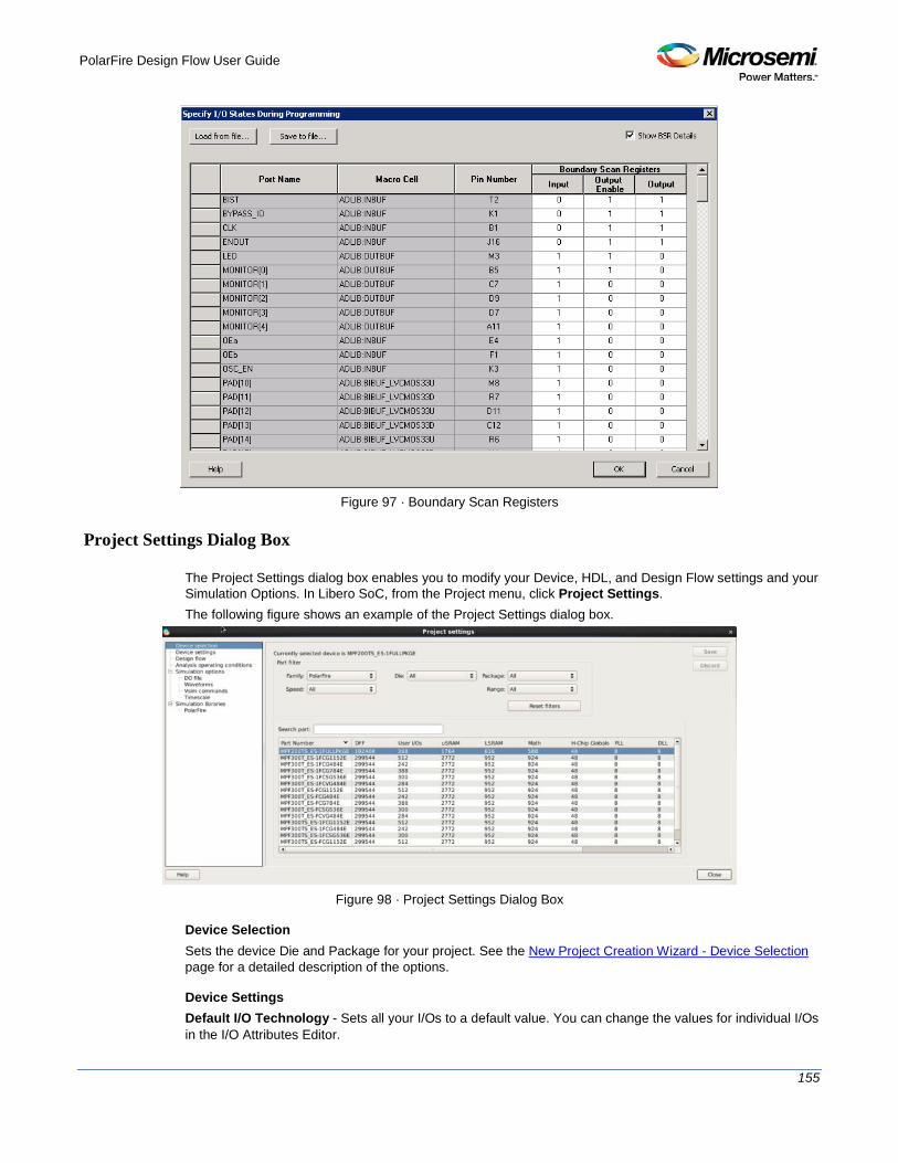
PolarFire Design Flow User Guide
155
Figure 97 · Boundary Scan Registers
Project Settings Dialog Box
The Project Settings dialog box enables you to modify your Device, HDL, and Design Flow settings and your Simulation Options. In Libero SoC, from the Project menu, click Project Settings. The following figure shows an example of the Project Settings dialog box.
Figure 98 · Project Settings Dialog Box
Device Selection Sets the device Die and Package for your project. See the New Project Creation Wizard - Device Selection page for a detailed description of the options.
Device Settings Default I/O Technology - Sets all your I/Os to a default value. You can change the values for individual I/Os in the I/O Attributes Editor.

PolarFire Design Flow User Guide
156
System controller suspended mode - When enabled (usually for safety-critical applications), the System Controller is held in a reset state after the completion of device initialization. This state protects the device from unintended device programming or zeroization of the device due to SEUs (Single Event Upsets). In this mode, the System Controller cannot provide any system services such as Flash*Freeze service, cryptographic services or programming services.
Design Flow See the Project Settings: Design flow topic for more information.
Analysis Operating Conditions Sets the Operating Temperature Range, the Core Voltage Range, and Default I/O Voltage Range from the picklist's provided. Typical values are COM/IND/MIL; but others are sometimes defined. Only EXT and IND ranges are available for PolarFire at present. Once the "Range" value is set, the Minimum/Typical/Maximum values for the selected range are displayed. These settings are propagated to Verify Timing, Verify Power, and Backannotated Netlist for you to perform Timing/Power Analysis.
Simulation Options and Simulation Libraries Sets your simulation options. See the Project Settings: Simulation Options topic for more information.
Project Settings: Simulation
To access this dialog box, from the Project menu choose Project Settings and click Simulation options > DO File. Use the Simulation tab to set your simulation values in your project. You can set change how Libero SoC handles Do files in simulation, import your own Do files, set simulation run time, and change the DUT name used in your simulation. You can also change your library mapping in this dialog box.
Figure 99 · Project Settings: DO File
DO file • Use automatic DO file - Select if you want the Project Manager to automatically create a DO file that
will enable you to simulate your design. • Simulation Run Time - Specify how long the simulation should run. If the value is 0, or if the field is
empty, there will not be a run command included in the run.do file. • Testbench module name - Specify the name of your testbench entity name. Default is “testbench,”
the value used by WaveFormer Pro.

PolarFire Design Flow User Guide
157
• Top Level instance name - Default is <top_0>, the value used by WaveFormer Pro. The Project Manager replaces <top> with the actual top level macro when you run simulation (presynth/postsynth/postlayout).
• Generate VCD file - Click the checkbox to generate a VCD file. • VCD file name - Specifies the name of your generated VCD file. The default is power.vcd; click
power.vcd and type to change the name. • User defined DO file - Enter the DO file name or click the browse button to navigate to it. • DO command parameters - Text in this field is added to the DO command.
Waveforms • Include DO file - Including a DO file enables you to customize the set of signal waveforms that will be
displayed in ModelSim. • Display waveforms for - You can display signal waveforms for either the top-level testbench or for the
design under test. If you select top-level testbench then Project Manager outputs the line 'add wave /testbench/*' in the DO file run.do. If you select DUT then Project Manager outputs the line 'add wave /testbench/DUT/*' in the run.do file.
• Log all signals in the design - Saves and logs all signals during simulation.
Vsim Commands • SDF timing delays - Select Minimum (Min), Typical (Typ), or Maximum (Max) timing delays in the
back-annotated SDF file. • Disable Pulse Filtering during SDF-based Simulations - When the check box is enabled the
+pulse_int_e/1 +pulse_int_r/1 +transport_int_delays switch is included with the vsim command for post-layout simulations; the checkbox is disabled by default.
• Resolution - The default is 1ps. • Additional options - Text entered in this field is added to the vsim command.
Timescale TimeUnit - Enter a value and select s, ms, us, ns, ps, or fs from the pull-down list, which is the time base for each unit. The default setting is ns. Precision - Enter a value and select s, ms, us, ns, ps, or fs from the pull-down list. The default setting is ps.
Simulation Libraries Use default library path - Sets the library path to default from your Libero SoC installation. Library path - Enables you to change the mapping for your simulation library (both Verilog and VHDL). Type the pathname or click the Browse button to navigate to your library directory.
Project Settings: Design flow
To access the Design flow page, from the Project menu choose Project Settings and click the Design flow tab.

PolarFire Design Flow User Guide
158
Figure 100 · Project Settings Dialog Box – Design Flow Tab
HDL source files language options
Libero SoC supports mixed-HDL language designs. You can import Verilog and VHDL in the same project. Sets your HDL to VHDL or Verilog. For VHDL, you can choose VHDL-2008 or VHDL-93. For Verilog, you can choose System Verilog (if your Verilog files contain System Verilog constructs) or Verilog 2001. Note: Libero SoC supports the following Verilog and VHDL IEEE standards: • Verilog 2005 (IEEE Standard 1364-2005) • Verilog 2001 (IEEE Standard 1364-2001) • Verilog 1995 (IEEE Standard 1364-1995) • SystemVerilog 2012 (IEEE Standard 1800-2012) • VHDL-2008 (IEEE Standard 1076-2008) • VHDL-93 (IEEE Standard 1076-1993)
HDL generated files language options
HDL files generated by Libero SoC can be set to use VHDL or Verilog. If there are no other considerations, it is generally recommended to use the same HDL language as you are using for HDL source files, as this may reduce the cost of simulation licenses.
Block flow
Enable block creation - Enables you to create and publish design blocks (*.cxz files) in Libero SoC. Design blocks are low-level components that may have completed the place-and-route step and met the timing and power requirements. These low-level design blocks can then be imported into a Libero SoC project and re-used as components in a higher level design. See Designing with Designer Block Components in Online Help for more information.
Design Hierarchy Build
Enable On Demand Build Design Hierarchy - Allows you to build the design hierarchy on demand and avoid the automatic build. This option is enabled by default for PolarFire devices.

PolarFire Design Flow User Guide
159
Reports
Maximum number of high fanout nets to be displayed - Enter the number of high fanout nets to be displayed. The default value is 10. This means the top 10 nets with the highest fanout will appear in the <root>_compile_netlist_resource.xml> Report.
Abort Flow Conditions
Abort Flow if Errors are found in Physical Design Constraints (PDC) – (Enhanced Constraint Flow only) Check this checkbox to abort Place and Route if the I/O or Floorplanning PDC constraint file contains errors. Abort Flow if Errors are found in Timing Constraints (SDC) – (Enhanced Constraint Flow only) Check this checkbox to abort Place and Route if the Timing Constraint SDC file contains errors.
remove_clock_groups
This Tcl command removes a clock group by name or by ID.
remove_clock_groups [-id id# | –name groupname] \ [-physically_exclusive | -logically_exclusive | -asynchronous]
Note: The exclusive flag is not needed when removing a clock group by ID.
Arguments -id id#
Specifies the clock group by the ID. -name groupname
Specifies the clock group by name (to be always followed by the exclusive flag). [-physically_exclusive | -logically_exclusive | - asynchronous]
Supported Families
Example Removal by group name
remove_clock_groups –name mygroup3 –physically_exclusive
Removal by goup ID remove_clock_groups –id 12
See Also set_clock_groups list_clock_groups
Search in Libero SoC
Search options vary depending on your search type.
To find a file: 1. Use CTRL + F to open the Search window. 2. Enter the name or part of name of the object you wish to find in the Find field. '*' indicates a wildcard,
and [*-*] indicates a range, such as if you search for a1, a2, ... a5 with the string a[1-5]. 3. Set the Options for your search (see below for list); options vary depending on your search type. 4. Click Find All (or Next if searching Text).

PolarFire Design Flow User Guide
160
Searching an open text file, Log window or Reports highlights search results in the file itself. All other results appear in the Search Results window (as shown in the figure below).
Match case: Select to search for case-sensitive occurrences of a word or phrase. This limits the search so it only locates text that matches the upper- and lowercase characters you enter. Match whole word: Select to match the whole word only.
Figure 101 · Search Results
Current Open SmartDesign Searches your open SmartDesign, returns results in the Search window. Type: Choose Instance, Net or Pin to narrow your search. Query: Query options vary according to Type.
Type Query Option Function
Instance Get Pins Search restricted to all pins
Get Nets Search restricted to all nets
Get Unconnected Pins Search restricted to all unconnected pins
Net Get Instances Searches all instances
Get Pins Search restricted to all pins
Pin Get Connected Pins Search restricted to all connected pins
Get Associated Net Search restricted to associated nets
Get All Unconnected Pins Search restricted to all unconnected pins
Current Open Text Editor Searches the open text file. If you have more than one text file open you must place the cursor in it and click CTRL + F to search it. Find All: Highlights all finds in the text file. Next: Proceed to next instance of found text. Previous: Proceed to previous instance of found text. Replace with: Replaces the text you searched with the contents of the field. Replace: Replaces a single instance. Replace All: Replaces all instances of the found text with the contents of the field.
Design Hierarchy Searches your Design Hierarchy; results appear in the Search window. Find All: Displays all finds in the Search window.
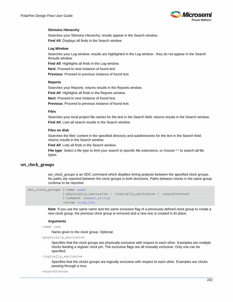
PolarFire Design Flow User Guide
161
Stimulus Hierarchy Searches your Stimulus Hierarchy; results appear in the Search window. Find All: Displays all finds in the Search window.
Log Window Searches your Log window; results are highlighted in the Log window - they do not appear in the Search Results window. Find All: Highlights all finds in the Log window. Next: Proceed to next instance of found text. Previous: Proceed to previous instance of found text.
Reports Searches your Reports; returns results in the Reports window. Find All: Highlights all finds in the Reports window. Next: Proceed to next instance of found text. Previous: Proceed to previous instance of found text.
Files Searches your local project file names for the text in the Search field; returns results in the Search window. Find All: Lists all search results in the Search window.
Files on disk Searches the files' content in the specified directory and subdirectories for the text in the Search field; returns results in the Search window. Find All: Lists all finds in the Search window. File type: Select a file type to limit your search to specific file extensions, or choose *.* to search all file types.
set_clock_groups
set_clock_groups is an SDC command which disables timing analysis between the specified clock groups. No paths are reported between the clock groups in both directions. Paths between clocks in the same group continue to be reported.
set_clock_groups [-name name] [-physically_exclusive | -logically_exclusive | -asynchronous] [-comment comment_string] -group clock_list
Note: If you use the same name and the same exclusive flag of a previously defined clock group to create a new clock group, the previous clock group is removed and a new one is created in its place.
Arguments -name name
Name given to the clock group. Optional. -physically_exclusive
Specifies that the clock groups are physically exclusive with respect to each other. Examples are multiple clocks feeding a register clock pin. The exclusive flags are all mutually exclusive. Only one can be specified.
-logically_exclusive
Specifies that the clocks groups are logically exclusive with respect to each other. Examples are clocks passing through a mux.
-asynchronous

PolarFire Design Flow User Guide
162
Specifies that the clock groups are asynchronous with respect to each other, as there is no phase relationship between them. The exclusive flags are all mutually exclusive. Only one can be specified.
Note: The exclusive flags for the arguments above are all mutually exclusive. Only one can be specified. -group clock_list
Specifies a list of clocks. There can any number of groups specified in the set_clock_groups command.
Example set_clock_groups –name mygroup3 –physically_exclusive \
–group [get_clocks clk_1] –group [get_clocks clk_2]
See Also list_clock_groups remove_clock_groups
set_clock_uncertainty
Tcl command; specifies a clock-to-clock uncertainty between two clocks (from and to) and returns the ID of the created constraint if the command succeeded.
set_clock_uncertainty uncertainty -from | -rise_from | -fall_from from_clock_list -to | -rise_to | -fall_to to_clock_list -setup {value} -hold {value}
Arguments uncertainty
Specifies the time in nanoseconds that represents the amount of variation between two clock edges. -from
Specifies that the clock-to-clock uncertainty applies to both rising and falling edges of the source clock list. Only one of the -from, -rise_from, or -fall_from arguments can be specified for the constraint to be valid.
-rise_from
Specifies that the clock-to-clock uncertainty applies only to rising edges of the source clock list. Only one of the -from, -rise_from, or -fall_from arguments can be specified for the constraint to be valid.
-fall_from
Specifies that the clock-to-clock uncertainty applies only to falling edges of the source clock list. Only one of the -from, -rise_from, or -fall_from arguments can be specified for the constraint to be valid.
from_clock_list
Specifies the list of clock names as the uncertainty source. -to
Specifies that the clock-to-clock uncertainty applies to both rising and falling edges of the destination clock list. Only one of the -to, -rise_to , or -fall_to arguments can be specified for the constraint to be valid.
-rise_to
Specifies that the clock-to-clock uncertainty applies only to rising edges of the destination clock list. Only one of the -to, -rise_to , or -fall_to arguments can be specified for the constraint to be valid.
-fall_to
Specifies that the clock-to-clock uncertainty applies only to falling edges of the destination clock list. Only one of the -to, -rise_to , or -fall_to arguments can be specified for the constraint to be valid.
to_clock_list
Specifies the list of clock names as the uncertainty destination. -setup
Specifies that the uncertainty applies only to setup checks. If none or both -setup and -hold are present, the uncertainty applies to both setup and hold checks.

PolarFire Design Flow User Guide
163
-hold
Specifies that the uncertainty applies only to hold checks. If none or both -setup and -hold are present, the uncertainty applies to both setup and hold checks.
Description The set_clock_uncertainty command sets the timing uncertainty between two clock waveforms or maximum clock skew. Timing between clocks have no uncertainty unless you specify it.
Examples set_clock_uncertainty 10 -from Clk1 -to Clk2
set_clock_uncertainty 0 -from Clk1 -fall_to { Clk2 Clk3 } -setup
set_clock_uncertainty 4.3 -fall_from { Clk1 Clk2 } -rise_to *
set_clock_uncertainty 0.1 -rise_from [ get_clocks { Clk1 Clk2 } ] -fall_to { Clk3 Clk4 } -setup
set_clock_uncertainty 5 -rise_from Clk1 -to [ get_clocks {*} ]
Organize Source Files Dialog Box – Synthesis
The Organize Source Files dialog box enables you to set the source file order in the Libero SoC. Click the Use list of files organized by User radio button to Add/Remove source files for the selected tool.
To specify the file order: 1. In the Design Flow window under Implement Design, right-click Synthesize and choose Organize
Input Files > Organize Source Files. The Organize Source Files dialog box appears. 2. Click the Use list of files organized by User radio button to Add/Remove source files for the selected
tool. 3. Select a file and click the Add or Remove buttons as necessary. Use the Up and Down arrows to
change the order of the Associated Source files. 4. Click OK.
Figure 102 · Organize Source Files Dialog Box
Stimulus Hierarchy
To view the Stimulus Hierarchy, from the View menu choose Windows > Stimulus Hierarchy.

PolarFire Design Flow User Guide
164
The Stimulus Hierarchy tab displays a hierarchical representation of the stimulus and simulation files in the project. The software continuously analyzes and updates files and content. The tab (see figure below) displays the structure of the modules and component stimulus files as they relate to each other.
Figure 103 · Stimulus Hierarchy Dialog Box
Expand the hierarchy to view stimulus and simulation files. Right-click an individual component and choose Show Module to view the module for only that component. Select Components, instance or Modules from the Show drop-down list to change the display mode. The Components view displays the stimulus hierarchy; the modules view displays HDL modules and stimulus files. The file name (the file that defines the module or component) appears in parentheses. Click Show Root Testbenches to view only the root-level testbenches in your design. Right-click and choose Properties; the Properties dialog box displays the pathname, created date, and last modified date. All integrated source editors are linked with the SoC software; if you modify a stimulus file the Stimulus Hierarchy automatically updates to reflect the change.
To open a stimulus file: Double-click a stimulus file to open it in the HDL text editor. Right-click and choose Delete from Project to delete the file from the project. Right-click and choose Delete from Disk and Project to remove the file from your disk. Icons in the Hierarchy indicate the type of component and the state, as shown in the table below.

PolarFire Design Flow User Guide
165
Timing Exceptions Overview
Use timing exceptions to overwrite the default behavior of the design path. Timing exceptions include: • Setting multicycle constraint to specify paths that (by design) will take more than one cycle. • Setting a false path constraint to identify paths that must not be included in the timing analysis or the
optimization flow. • Setting a maximum delay constraint on specific paths to relax or to tighten the original clock constraint
requirement.
Tool Profiles Dialog Box
The Tool Profiles dialog box enables you to add, edit, or delete your project tool profiles. Each Libero SoC project can have a different profile, enabling you to integrate different tools with different projects.
To set or change your tool profile: 1. From the Project menu, choose Tool Profiles. Select the type of tool you wish to add.
• To add a tool: Select the tool type and click the Add button . Fill out the tool profile and click OK.
• To change a tool profile: After selecting the tool, click the Edit button to select another tool, change the tool name, or change the tool location.
• To remove a tool from the project:After selecting a tool, click the Remove button. 2. When you are done, click OK.
Figure 104 · Libero SoC Tool Profiles Dialog Box
The tool profile with the padlock icon indicates that it is a pre-defined tool profile (the default tool that comes with the Libero SoC Installation.) To export the tool profile and save it for future use, click the Export Tool Profiles dialog box and save the tool profile file as a tool profile *.ini file. The tool profile *.ini file can be imported into a Libero SoC project (File > Import > Others) and select Tool Profiles (*.ini) in the File Type pull-down list.
User Preferences Dialog Box – Design Flow Preferences
This dialog box allows you to set your personal preferences for how Libero SoC manages the design flow across the projects you create.

PolarFire Design Flow User Guide
166
Figure 105 · Preferences Dialog Box – Design Flow Preferences
Constraint Flow • Use enhanced constraint flow when creating a new project.
The Enhanced Constraint Flow provides a centralized graphical interface for you to better manage all your design constraint files in the design process. The Enhanced Constraint Flow is the only design flow supported for PolarFire, and cannot be turned off.
• Show classic/enhanced constraint flow choice dialog when creating a new project. Since the Enhanced Constraint Flow is the only flow supported for PolarFire, this option has no effect.
• Warn me when derived timing constraints generation override existing constraints (enhanced constraint flow). Libero SoC can generate/derive timing constraints for known hardware blocks and IPs such as SERDES, CCC. Check this box to have Libero SoC pop up a warning message when the generated timing constraints for these blocks override the timing constraints you set for these blocks. This box is checked by default.
Design Flow Rule Checks • Warn me when Firmware applications must be recompiled because of hardware configuration
changes. Check this box if you want Libero SoC to display a warning message. This box is checked by default.
• Warn me when I/Os are not all assigned and locked before programming data generation. I/Os should always be assigned and locked before programming data generation. Check this box if you want Libero SoC to display a warning message. This box is checked by default.
SmartDesign Generation Options • Generate recursively
In this mode, all subdesigns must be successfully generated before a parent can be generated. An attempt to generate a SmartDesign results in an automatic attempt to generate all subdesigns.
• Generate non-recursively In this mode, the generation of only explicitly selected SmartDesigns is attempted. The generation of a design can be marked as successful even if a subdesign is ungenerated (either never attempted or unsuccessful).

PolarFire Design Flow User Guide
167
Note: These preferences are stored on a per-user basis across multiple projects; they are not project-specific.
Synopsys Design Constraints (SDC) Synopsys Design Constraints (SDC) is a Tcl-based format used by Synopsys tools to specify the design intent, including the timing and area constraints for a design. Microsemi tools use a subset of the SDC format to capture supported timing constraints. Any timing constraint that you can enter using Designer tools can also be specified in an SDC file. Use the SDC-based flow to share timing constraint information between Microsemi tools and third-party EDA tools.
Command Action
create_clock Creates a clock and defines its characteristics
create_generated_clock Creates an internally generated clock and defines its characteristics
set_clock_latency Defines the delay between an external clock source and the definition pin of a clock within SmartTime
set_clock_uncertainty Defines the timing uncertainty between two clock waveforms or maximum skew
set_false_path Identifies paths that are to be considered false and excluded from the timing analysis
set_input_delay Defines the arrival time of an input relative to a clock
set_max_delay Specifies the maximum delay for the timing paths
set_min_delay Specifies the minimum delay for the timing paths
set_multicycle_path Defines a path that takes multiple clock cycles
set_output_delay Defines the output delay of an output relative to a clock
See Also SDC Syntax Conventions
libero_design_flow_SDC_commands
SDC Syntax Conventions
The following table shows the typographical conventions that are used for the SDC command syntax.
Syntax Notation Description
command -argument Commands and arguments appear in Courier New typeface.
variable Variables appear in blue, italic Courier New typeface. You must substitute an appropriate value for the variable.
[-argument value] Optional arguments begin and end with a square bracket.

PolarFire Design Flow User Guide
168
Note: SDC commands and arguments are case sensitive.
Example The following example shows syntax for the create_clock command and a sample command:
create_clock -period period_value [-waveform edge_list] source
create_clock –period 7 –waveform {2 4}{CLK1}
Wildcard Characters You can use the following wildcard characters in names used in the SDC commands:
Wildcard What it does
\ Interprets the next character literally
* Matches any string
Note: The matching function requires that you add a backslash (\) before each slash in the pin names in
case the slash does not denote the hierarchy in your design.
Special Characters ([ ], { }, and \) Square brackets ([ ]) are part of the command syntax to access ports, pins and clocks. In cases where these netlist objects names themselves contain square brackets (for example, buses), you must either enclose the names with curly brackets ({}) or precede the open and closed square brackets ([ ]) characters with a backslash (\). If you do not do this, the tool displays an error message. For example:
create_clock -period 3 clk\[0\]
set_max_delay 1.5 -from [get_pins ff1\[5\]:CLK] -to [get_clocks {clk[0]}]
Although not necessary, Microsemi recommends the use of curly brackets around the names, as shown in the following example:
set_false_path –from {data1} –to [get_pins {reg1:D}]
In any case, the use of the curly bracket is mandatory when you have to provide more than one name. For example:
set_false_path –from {data3 data4} –to [get_pins {reg2:D reg5:D}]
Entering Arguments on Separate Lines If a command needs to be split on multiple lines, each line except the last must end with a backslash (\) character as shown in the following example:
set_multicycle_path 2 –from \
[get_pins {reg1*}] \
-to {reg2:D}
See Also About SDC Files
create_clock
SDC command; creates a clock and defines its characteristics.
create_clock -name name -period period_value [-waveform edge_list] source

PolarFire Design Flow User Guide
169
Arguments -name name
Specifies the name of the clock constraint. This parameter is required for virtual clocks when no clock source is provided.
-period period_value
Specifies the clock period in nanoseconds. The value you specify is the minimum time over which the clock waveform repeats. The period_value must be greater than zero.
-waveform edge_list
Specifies the rise and fall times of the clock waveform in ns over a complete clock period. There must be exactly two transitions in the list, a rising transition followed by a falling transition. You can define a clock starting with a falling edge by providing an edge list where fall time is less than rise time. If you do not specify -waveform option, the tool creates a default waveform, with a rising edge at instant 0.0 ns and ©a falling edge at instant (period_value/2)ns.
source
Specifies the source of the clock constraint. The source can be ports or pins in the design. If you specify a clock constraint on a pin that already has a clock, the new clock replaces the existing one. Only one source is accepted. Wildcards are accepted as long as the resolution shows one port or pin.
Description Creates a clock in the current design at the declared source and defines its period and waveform. The static timing analysis tool uses this information to propagate the waveform across the clock network to the clock pins of all sequential elements driven by this clock source. The clock information is also used to compute the slacks in the specified clock domain that drive optimization tools such as place-and-route.
Exceptions • None
Examples The following example creates two clocks on ports CK1 and CK2 with a period of 6, a rising edge at 0, and a falling edge at 3:
create_clock -name {my_user_clock} -period 6 CK1
create_clock -name {my_other_user_clock} –period 6 –waveform {0 3} {CK2}
The following example creates a clock on port CK3 with a period of 7, a rising edge at 2, and a falling edge at 4:
create_clock –period 7 –waveform {2 4} [get_ports {CK3}]
Microsemi Implementation Specifics • The -waveform in SDC accepts waveforms with multiple edges within a period. In Microsemi design
implementation, only two waveforms are accepted. • SDC accepts defining a clock on many sources using a single command. In Microsemi design
implementation, only one source is accepted. • The source argument in SDC create_clock command is optional. This is in conjunction with the -name
argument in SDC to support the concept of virtual clocks. In Microsemi implementation, source is a mandatory argument as -name and virtual clocks concept is not supported.
• The -domain argument in the SDC create_clock command is not supported.
See Also SDC Syntax Conventions

PolarFire Design Flow User Guide
170
create_generated_clock
SDC command; creates an internally generated clock and defines its characteristics.
create_generated_clock -name {name -source reference_pin [-divide_by divide_factor] [-multiply_by multiply_factor] [-invert] source -pll_output pll_feedback_clock -pll_feedback pll_feedback_input
Arguments -name name
Specifies the name of the clock constraint. This parameter is required for virtual clocks when no clock source is provided.
-source reference_pin
Specifies the reference pin in the design from which the clock waveform is to be derived. -divide_bydivide_factor
Specifies the frequency division factor. For instance if the divide_factor is equal to 2, the generated clock period is twice the reference clock period.
-multiply_by multiply_factor
Specifies the frequency multiplication factor. For instance if the multiply_factor is equal to 2, the generated clock period is half the reference clock period.
-invert
Specifies that the generated clock waveform is inverted with respect to the reference clock. source
Specifies the source of the clock constraint on internal pins of the design. If you specify a clock constraint on a pin that already has a clock, the new clock replaces the existing clock. Only one source is accepted. Wildcards are accepted as long as the resolution shows one pin.
-pll_output pll_feedback_clock
Specifies the output pin of the PLL which is used as the external feedback clock. This pin must drive the feedback input pin of the PLL specified using the –pll_feedback option. The PLL will align the rising edge of the reference input clock to the feedback clock. This is a mandatory argument if the PLL is operating in external feedback mode.
-pll_feedback pll_feedback_input
Specifies the feedback input pin of the PLL. This pin must be driven by the output pin of the PLL specified using the –pll_output option. The PLL will align the rising edge of the reference input clock to the external feedback clock. This is a mandatory argument if the PLL is operating in external feedback mode.
Description Creates a generated clock in the current design at a declared source by defining its frequency with respect to the frequency at the reference pin. The static timing analysis tool uses this information to compute and propagate its waveform across the clock network to the clock pins of all sequential elements driven by this source. The generated clock information is also used to compute the slacks in the specified clock domain that drive optimization tools such as place-and-route.
Examples The following example creates a generated clock on pin U1/reg1:Q with a period twice as long as the period at the reference port CLK.
create_generated_clock -name {my_user_clock} –divide_by 2 –source [get_ports {CLK}] U1/reg1/Q
The following example creates a generated clock at the primary output of myPLL with a period ¾ of the period at the reference pin clk.

PolarFire Design Flow User Guide
171
create_generated_clock –divide_by 3 –multiply_by 4 -source clk [get_pins {myPLL/CLK1}]
The following example creates a generated clock named system_clk on the GL2 output pin of FCCC_0 with a period equal to half the period of the source clock. The constraint also identifies GL2 output pin as the external feedback clock source and CLK2 as the feedback input pin for FCCC_0.
create_generated_clock -name { system_clk } \
-multiply_by 2 \
-source { FCCC_0/CCC_INST/CLK3_PAD } \
-pll_output { FCCC_0/CCC_INST/GL2 } \
-pll_feedback { FCCC_0/CCC_INST/CLK2 } \
{ FCCC_0/CCC_INST/GL2 }
Microsemi Implementation Specifics • SDC accepts either –multiply_by or –divide_by option. In Microsemi design implementation, both are
accepted to accurately model the PLL behavior. • SDC accepts defining a generated clock on many sources using a single command. In Microsemi
design implementation, only one source is accepted. • The -duty_cycle ,-edges and –edge_shift options in the SDC create_generated_clock command are
not supported in Microsemi design implementation.
See Also SDC Syntax Conventions
set_clock_latency
SDC command; defines the delay between an external clock source and the definition pin of a clock within SmartTime.
set_clock_latency -source [-rise][-fall][-early][-late] delay clock
Arguments -source
Specifies a clock source latency on a clock pin. -rise
Specifies the edge for which this constraint will apply. If neither or both rise are passed, the same latency is applied to both edges.
-fall
Specifies the edge for which this constraint will apply. If neither or both rise are passed, the same latency is applied to both edges.
-invert
Specifies that the generated clock waveform is inverted with respect to the reference clock. -late
Optional. Specifies that the latency is late bound on the latency. The appropriate bound is used to provide the most pessimistic timing scenario. However, if the value of "-late" is less than the value of "-early", optimistic timing takes place which could result in incorrect analysis. If neither or both "-early" and "-late" are provided, the same latency is used for both bounds, which results in the latency having no effect for single clock domain setup and hold checks.
-early
Optional. Specifies that the latency is early bound on the latency. The appropriate bound is used to provide the most pessimistic timing scenario. However, if the value of "-late" is less than the value of "-early", optimistic timing takes place which could result in incorrect analysis. If neither or both "-early" and

PolarFire Design Flow User Guide
172
"-late" are provided, the same latency is used for both bounds, which results in the latency having no effect for single clock domain setup and hold checks.
delay
Specifies the latency value for the constraint. clock
Specifies the clock to which the constraint is applied. This clock must be constrained.
Description Clock source latency defines the delay between an external clock source and the definition pin of a clock within SmartTime. It behaves much like an input delay constraint. You can specify both an "early" delay and a"late" delay for this latency, providing an uncertainty which SmartTime propagates through its calculations. Rising and falling edges of the same clock can have different latencies. If only one value is provided for the clock source latency, it is taken as the exact latency value, for both rising and falling edges.
Exceptions None
Examples The following example sets an early clock source latency of 0.4 on the rising edge of main_clock. It also sets a clock source latency of 1.2, for both the early and late values of the falling edge of main_clock. The late value for the clock source latency for the falling edge of main_clock remains undefined.
set_clock_latency –source –rise –early 0.4 { main_clock }
set_clock_latency –source –fall 1.2 { main_clock }
Microsemi Implementation Specifics SDC accepts a list of clocks to -set_clock_latency. In Microsemi design implementation, only one clock pin can have its source latency specified per command.
See Also SDC Syntax Conventions
set_clock_to_output
SDC command; defines the timing budget available inside the FPGA for an output relative to a clock.
set_clock_to_output delay_value -clock clock_ref [–max] [–min] output_list
Arguments delay_value
Specifies the clock to output delay in nanoseconds. This time represents the amount of time available inside the FPGA between the active clock edge and the data change at the output port.
-clock clock_ref
Specifies the reference clock to which the specified clock to output is related. This is a mandatory argument.
-max
Specifies that delay_value refers to the maximum clock to output at the specified output. If you do not specify –max or –min options, the tool assumes maximum and minimum clock to output delays to be equal.
-min
Specifies that delay_value refers to the minimum clock to output at the specified output. If you do not specify –max or –min options, the tool assumes maximum and minimum clock to output delays to be equal.

PolarFire Design Flow User Guide
173
output_list
Provides a list of output ports in the current design to which delay_value is assigned. If you need to specify more than one object, enclose the objects in braces ({}).
set_clock_uncertainty
SDC command; defines the timing uncertainty between two clock waveforms or maximum skew.
set_clock_uncertainty uncertainty (-from | -rise_from | -fall_from) from_clock_list (-to | -rise_to | -fall_to) to_clock_list [-setup | -hold]
Arguments uncertainty
Specifies the time in nanoseconds that represents the amount of variation between two clock edges. The value must be a positive floating point number.
-from
Specifies that the clock-to-clock uncertainty applies to both rising and falling edges of the source clock list. You can specify only one of the -from, -rise_from, or -fall_from arguments for the constraint to be valid. This option is the default.
-rise_from
Specifies that the clock-to-clock uncertainty applies only to rising edges of the source clock list. You can specify only one of the -from, -rise_from, or -fall_from arguments for the constraint to be valid.
-fall_from
Specifies that the clock-to-clock uncertainty applies only to falling edges of the source clock list. You can specify only one of the -from, -rise_from, or -fall_from arguments for the constraint to be valid.
from_clock_list
Specifies the list of clock names as the uncertainty source. -to
Specifies that the clock-to-clock uncertainty applies to both rising and falling edges of the destination clock list. You can specify only one of the -to, -rise_to , or -fall_to arguments for the constraint to be valid.
-rise_to
Specifies that the clock-to-clock uncertainty applies only to rising edges of the destination clock list. You can specify only one of the -to, -rise_to , or -fall_to arguments for the constraint to be valid.
-fall_to
Specifies that the clock-to-clock uncertainty applies only to falling edges of the destination clock list. You can specify only one of the -to, -rise_to , or -fall_to arguments for the constraint to be valid.
to_clock_list
Specifies the list of clock names as the uncertainty destination. -setup
Specifies that the uncertainty applies only to setup checks. If you do not specify either option (-setup or -hold ) or if you specify both options, the uncertainty applies to both setup and hold checks.
-hold
Specifies that the uncertainty applies only to hold checks. If you do not specify either option (-setup or -hold ) or if you specify both options, the uncertainty applies to both setup and hold checks.
Description Clock uncertainty defines the timing between an two clock waveforms or maximum clock skew. Both setup and hold checks must account for clock skew. However, for setup check, SmartTime looks for the smallest skew. This skew is computed by using the maximum insertion delay to the launching sequential component and the shortest insertion delay to the receiving component.

PolarFire Design Flow User Guide
174
For hold check, SmartTime looks for the largest skew. This skew is computed by using the shortest insertion delay to the launching sequential component and the largest insertion delay to the receiving component. SmartTime makes this distinction automatically.
Exceptions None
Examples The following example defines two clocks and sets the uncertainty constraints, which analyzes the inter-clock domain between clk1 and clk2.
create_clock –period 10 clk1
create_generated_clock –name clk2 -source clk1 -multiply_by 2 sclk1
set_clock_uncertainty 0.4 -rise_from clk1 -rise_to clk2
Microsemi Implementation Specifics • SDC accepts a list of clocks to -set_clock_uncertainty.
See Also SDC Syntax Conventions
set_disable_timing
SDC command; disables timing arcs within the specified cell and returns the ID of the created constraint if the command succeeded.
set_disable_timing [-from from_port] [-to to_port] cell_name
Arguments -from from_port
Specifies the starting port. -to to_port
Specifies the ending port. cell_name
Specifies the name of the cell in which timing arcs will be disabled.
Description This command disables the timing arcs in the specified cell, and returns the ID of the created constraint if the command succeeded. The –from and –to arguments must either both be present or both omitted for the constraint to be valid.
Examples The following example disables the arc between a2:A and a2:Y.
set_disable_timing -from port1 -to port2 cellname
This command ensures that the arc is disabled within a cell instead of between cells.
Microsemi Implementation Specifics • None
See Also SDC Syntax Conventions

PolarFire Design Flow User Guide
175
set_external_check
SDC command; defines the external setup and hold delays for an input relative to a clock.
set_external_check delay_value -clock clock_ref [–setup] [–hold] [–clock_fall] input_list
Arguments delay_value
Specifies the external setup or external hold delay in nanoseconds. This time represents the amount of time available inside the FPGA for the specified input after a clock edge.
-clock clock_ref
Specifies the reference clock to which the specified external check is related. This is a mandatory argument.
-setup
Specifies that delay_value refers to the setup check at the specified input. This is a mandatory argument if –hold is not used. You must specify either -setup or -hold option.
-clock_fall
Specifies that the delay is relative to the falling edge of the reference clock. The default is the rising edge. input_list
Provides a list of input ports in the current design to which delay_value is assigned. If you need to specify more than one object, enclose the objects in braces ({}).
Description The set_external_check command specifies the external setup and hold times on input ports relative to a clock edge. This usually represents a combinational path delay from the input port to the clock pin of a register internal to the current design. For in/out (bidirectional) ports, you can specify the path delays for both input and output modes. The tool uses external setup and external hold times for paths starting at primary inputs. A clock is a singleton that represents the name of a defined clock constraint. This can be an object accessor that will refer to one clock. For example:
[get_clocks {system_clk}]
[get_clocks {sys*_clk}]
Examples The following example sets an external setup check of 12 ns and an external hold check of 6 ns for port data_in relative to the rising edge of CLK1:
set_external_check 12 -clock [get_clocks CLK1] -setup [get_ports data_in]
set_external_check 6 -clock [get_clocks CLK1] -hold [get_ports data_in]
See Also SDC Syntax Conventions
set_false_path
SDC command; identifies paths that are considered false and excluded from the timing analysis.
set_false_path [-from from_list] [-through through_list] [-to to_list]
Arguments -from from_list
Specifies a list of timing path starting points. A valid timing starting point is a clock, a primary input, an inout port, or a clock pin of a sequential cell.

PolarFire Design Flow User Guide
176
-through through_list
Specifies a list of pins, ports, cells, or nets through which the disabled paths must pass. -to to_list
Specifies a list of timing path ending points. A valid timing ending point is a clock, a primary output, an inout port, or a data pin of a sequential cell.
Description The set_false_path command identifies specific timing paths as being false. The false timing paths are paths that do not propagate logic level changes. This constraint removes timing requirements on these false paths so that they are not considered during the timing analysis. The path starting points are the input ports or register clock pins, and the path ending points are the register data pins or output ports. This constraint disables setup and hold checking for the specified paths. The false path information always takes precedence over multiple cycle path information and overrides maximum delay constraints. If more than one object is specified within one -through option, the path can pass through any objects.
Examples The following example specifies all paths from clock pins of the registers in clock domain clk1 to data pins of a specific register in clock domain clk2 as false paths:
set_false_path –from [get_clocks {clk1}] –to reg_2:D
The following example specifies all paths through the pin U0/U1:Y to be false: set_false_path -through U0/U1:Y
Microsemi Implementation Specifics SDC accepts multiple -through options in a single constraint to specify paths that traverse multiple points in the design. In Microsemi design implementation, only one –through option is accepted.
See Also SDC Syntax Conventions
set_input_delay
SDC command; defines the arrival time of an input relative to a clock.
set_input_delay delay_value -clock clock_ref [–max] [–min] [–clock_fall] input_list
Arguments delay_value
Specifies the arrival time in nanoseconds that represents the amount of time for which the signal is available at the specified input after a clock edge.
-clock clock_ref
Specifies the clock reference to which the specified input delay is related. This is a mandatory argument. If you do not specify -max or -min options, the tool assumes the maximum and minimum input delays to be equal.
-max
Specifies that delay_value refers to the longest path arriving at the specified input. If you do not specify -max or -min options, the tool assumes maximum and minimum input delays to be equal.
-min
Specifies that delay_value refers to the shortest path arriving at the specified input. If you do not specify -max or -min options, the tool assumes maximum and minimum input delays to be equal.
-clock_fall
Specifies that the delay is relative to the falling edge of the clock reference. The default is the rising edge.

PolarFire Design Flow User Guide
177
input_list
Provides a list of input ports in the current design to which delay_value is assigned. If you need to specify more than one object, enclose the objects in braces ({}).
Description The set_input_delay command sets input path delays on input ports relative to a clock edge. This usually represents a combinational path delay from the clock pin of a register external to the current design. For in/out (bidirectional) ports, you can specify the path delays for both input and output modes. The tool adds input delay to path delay for paths starting at primary inputs. A clock is a singleton that represents the name of a defined clock constraint. This can be: • a single port name used as source for a clock constraint • a single pin name used as source for a clock constraint; for instance reg1:CLK. This name can be
hierarchical (for instance toplevel/block1/reg2:CLK) • an object accessor that will refer to one clock: [get_clocks {clk}]
Examples The following example sets an input delay of 1.2ns for port data1 relative to the rising edge of CLK1:
set_input_delay 1.2 -clock [get_clocks CLK1] [get_ports data1]
The following example sets a different maximum and minimum input delay for port IN1 relative to the falling edge of CLK2:
set_input_delay 1.0 -clock_fall -clock CLK2 –min {IN1}
set_input_delay 1.4 -clock_fall -clock CLK2 –max {IN1}
Microsemi Implementation Specifics In SDC, the -clock is an optional argument that allows you to set input delay for combinational designs. Microsemi Implementation currently requires this argument.
See Also SDC Syntax Conventions
set_max_delay (SDC)
SDC command; specifies the maximum delay for the timing paths.
set_max_delay delay_value [-from from_list] [-to to_list]
Arguments delay_value
Specifies a floating point number in nanoseconds that represents the required maximum delay value for specified paths.
• If the path starting point is on a sequential device, the tool includes clock skew in the computed delay.
• If the path starting point has an input delay specified, the tool adds that delay value to the path delay.
• If the path ending point is on a sequential device, the tool includes clock skew and library setup time in the computed delay.
• If the ending point has an output delay specified, the tool adds that delay to the path delay. -from from_list
Specifies a list of timing path starting points. A valid timing starting point is a clock, a primary input, an inout port, or a clock pin of a sequential cell.
-to to_list

PolarFire Design Flow User Guide
178
Specifies a list of timing path ending points. A valid timing ending point is a clock, a primary output, an inout port, or a data pin of a sequential cell.
Description This command specifies the required maximum delay for timing paths in the current design. The path length for any startpoint in from_list to any endpoint in to_list must be less than delay_value. The tool automatically derives the individual maximum delay targets from clock waveforms and port input or output delays. For more information, refer to the create_clock, set_input_delay, and set_output_delay commands. The maximum delay constraint is a timing exception. This constraint overrides the default single cycle timing relationship for one or more timing paths. This constraint also overrides a multicycle path constraint.
Examples The following example sets a maximum delay by constraining all paths from ff1a:CLK or ff1b:CLK to ff2e:D with a delay less than 5 ns:
set_max_delay 5 -from {ff1a:CLK ff1b:CLK} -to {ff2e:D}
The following example sets a maximum delay by constraining all paths to output ports whose names start by “out” with a delay less than 3.8 ns:
set_max_delay 3.8 -to [get_ports out*]
Microsemi Implementation Specifics The –through option in the set_max_delay SDC command is not supported.
See Also SDC Syntax Conventions
set_min_delay
SDC command; specifies the minimum delay for the timing paths.
set_min_delay delay_value [-from from_list] [-to to_list]
Arguments delay_value
Specifies a floating point number in nanoseconds that represents the required minimum delay value for specified paths.
• If the path starting point is on a sequential device, the tool includes clock skew in the computed delay.
• If the path starting point has an input delay specified, the tool adds that delay value to the path delay.
• If the path ending point is on a sequential device, the tool includes clock skew and library setup time in the computed delay.
• If the ending point has an output delay specified, the tool adds that delay to the path delay.
-from from_list
Specifies a list of timing path starting points. A valid timing starting point is a clock, a primary input, an inout port, or a clock pin of a sequential cell.
-to to_list
Specifies a list of timing path ending points. A valid timing ending point is a clock, a primary output, an inout port, or a data pin of a sequential cell.
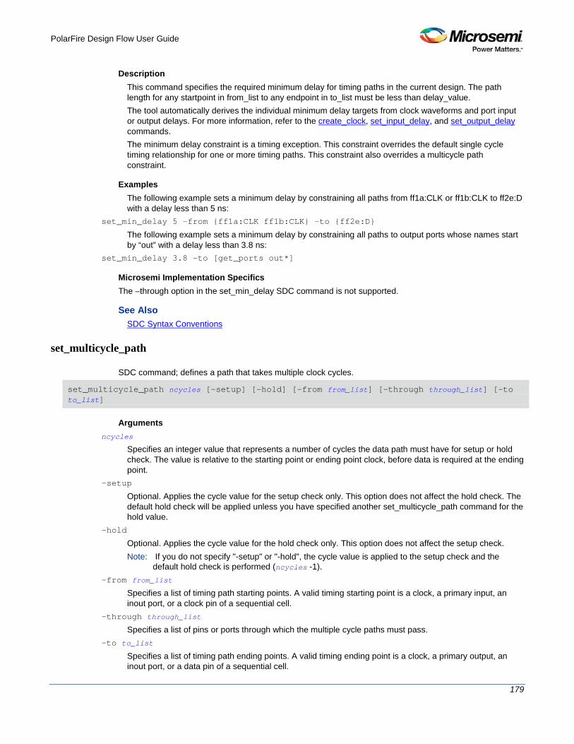
PolarFire Design Flow User Guide
179
Description This command specifies the required minimum delay for timing paths in the current design. The path length for any startpoint in from_list to any endpoint in to_list must be less than delay_value. The tool automatically derives the individual minimum delay targets from clock waveforms and port input or output delays. For more information, refer to the create_clock, set_input_delay, and set_output_delay commands. The minimum delay constraint is a timing exception. This constraint overrides the default single cycle timing relationship for one or more timing paths. This constraint also overrides a multicycle path constraint.
Examples The following example sets a minimum delay by constraining all paths from ff1a:CLK or ff1b:CLK to ff2e:D with a delay less than 5 ns:
set_min_delay 5 -from {ff1a:CLK ff1b:CLK} -to {ff2e:D}
The following example sets a minimum delay by constraining all paths to output ports whose names start by “out” with a delay less than 3.8 ns:
set_min_delay 3.8 -to [get_ports out*]
Microsemi Implementation Specifics The –through option in the set_min_delay SDC command is not supported.
See Also SDC Syntax Conventions
set_multicycle_path
SDC command; defines a path that takes multiple clock cycles.
set_multicycle_path ncycles [-setup] [-hold] [-from from_list] [–through through_list] [-to to_list]
Arguments ncycles
Specifies an integer value that represents a number of cycles the data path must have for setup or hold check. The value is relative to the starting point or ending point clock, before data is required at the ending point.
-setup
Optional. Applies the cycle value for the setup check only. This option does not affect the hold check. The default hold check will be applied unless you have specified another set_multicycle_path command for the hold value.
-hold
Optional. Applies the cycle value for the hold check only. This option does not affect the setup check. Note: If you do not specify "-setup" or "-hold", the cycle value is applied to the setup check and the
default hold check is performed (ncycles -1). -from from_list
Specifies a list of timing path starting points. A valid timing starting point is a clock, a primary input, an inout port, or a clock pin of a sequential cell.
-through through_list
Specifies a list of pins or ports through which the multiple cycle paths must pass. -to to_list
Specifies a list of timing path ending points. A valid timing ending point is a clock, a primary output, an inout port, or a data pin of a sequential cell.

PolarFire Design Flow User Guide
180
Description Setting multiple cycle paths constraint overrides the single cycle timing relationships between sequential elements by specifying the number of cycles that the data path must have for setup or hold checks. If you change the multiplier, it affects both the setup and hold checks. False path information always takes precedence over multiple cycle path information. A specific maximum delay constraint overrides a general multiple cycle path constraint. If you specify more than one object within one -through option, the path passes through any of the objects.
Examples The following example sets all paths between reg1 and reg2 to 3 cycles for setup check. Hold check is measured at the previous edge of the clock at reg2.
set_multicycle_path 3 -from [get_pins {reg1}] –to [get_pins {reg2}]
The following example specifies that four cycles are needed for setup check on all paths starting at the registers in the clock domain ck1. Hold check is further specified with two cycles instead of the three cycles that would have been applied otherwise.
set_multicycle_path 4 -setup -from [get_clocks {ck1}]
set_multicycle_path 2 -hold -from [get_clocks {ck1}]
Microsemi Implementation Specifics • SDC allows multiple priority management on the multiple cycle path constraint depending on the scope
of the object accessors. In Microsemi design implementation, such priority management is not supported. All multiple cycle path constraints are handled with the same priority.
See Also SDC Syntax Conventions
set_output_delay
SDC command; defines the output delay of an output relative to a clock.
set_output_delay delay_value -clock clock_ref [–max] [–min] [–clock_fall] output_list
Arguments delay_value
Specifies the amount of time before a clock edge for which the signal is required. This represents a combinational path delay to a register outside the current design plus the library setup time (for maximum output delay) or hold time (for minimum output delay).
-clock clock_ref
Specifies the clock reference to which the specified output delay is related. This is a mandatory argument. If you do not specify -max or -min options, the tool assumes the maximum and minimum input delays to be equal.
-max
Specifies that delay_value refers to the longest path from the specified output. If you do not specify -max or -min options, the tool assumes the maximum and minimum output delays to be equal.
-min
Specifies that delay_value refers to the shortest path from the specified output. If you do not specify -max or -min options, the tool assumes the maximum and minimum output delays to be equal.
-clock_fall
Specifies that the delay is relative to the falling edge of the clock reference. The default is the rising edge. output_list

PolarFire Design Flow User Guide
181
Provides a list of output ports in the current design to which delay_value is assigned. If you need to specify more than one object, enclose the objects in braces ({}).
Description The set_output_delay command sets output path delays on output ports relative to a clock edge. Output ports have no output delay unless you specify it. For in/out (bidirectional) ports, you can specify the path delays for both input and output modes. The tool adds output delay to path delay for paths ending at primary outputs.
Examples The following example sets an output delay of 1.2ns for port OUT1 relative to the rising edge of CLK1:
set_output_delay 1.2 -clock [get_clocks CLK1] [get_ports OUT1]
The following example sets a different maximum and minimum output delay for port OUT1 relative to the falling edge of CLK2:
set_output_delay 1.0 -clock_fall -clock CLK2 –min {OUT1}
set_output_delay 1.4 -clock_fall -clock CLK2 –max {OUT1}
Microsemi Implementation Specifics • In SDC, the -clock is an optional argument that allows you to set the output delay for combinational
designs. Microsemi Implementation currently requires this option.
See Also SDC Syntax Conventions
Design Object Access Commands
Design object access commands are SDC commands. Most SDC constraint commands require one of these commands as command arguments. Microsemi software supports the following SDC access commands:
Design Object Access Command
Cell get_cells
Clock get_clocks
Net get_nets
Port get_ports
Pin get_pins
Input ports all_inputs
Output ports all_outputs
Registers all_registers
See Also About SDC Files
all_inputs Design object access command; returns all the input or inout ports of the design.

PolarFire Design Flow User Guide
182
all_inputs
Arguments
• None
Exceptions
• None
Example
set_max_delay -from [all_inputs] -to [get_clocks ck1]
Microsemi Implementation Specifics
• None
See Also SDC Syntax Conventions
all_outputs Design object access command; returns all the output or inout ports of the design.
all_outputs
Arguments
• None
Exceptions
• None
Example
set_max_delay -from [all_inputs] -to [all_outputs]
Microsemi Implementation Specifics
None
See Also SDC Syntax Conventions
all_registers Design object access command; returns either a collection of register cells or register pins, whichever you specify.
all_registers [-clock clock_name] [-cells] [-data_pins ] [-clock_pins] [-async_pins] [-output_pins]

PolarFire Design Flow User Guide
183
Arguments
-clock clock_name
Creates a collection of register cells or register pins in the specified clock domain. -cells
Creates a collection of register cells. This is the default. This option cannot be used in combination with any other option.
-data_pins
Creates a collection of register data pins. -clock_pins
Creates a collection of register clock pins. -async_pins
Creates a collection of register asynchronous pins. -output_pins
Creates a collection of register output pins.
Description
This command creates either a collection of register cells (default) or register pins, whichever is specified. If you do not specify an option, this command creates a collection of register cells.
Exceptions
• None
Examples
set_max_delay 2 -from [all_registers] -to [get_ports {out}]
set_max_delay 3 –to [all_registers –async_pins]
set_false_path –from [all_registers –clock clk150]
set_multicycle_path –to [all_registers –clock c* -data_pins
–clock_pins]
Microsemi Implementation Specifics
• None
See Also SDC Syntax Conventions
get_cells Design object access command; returns the cells (instances) specified by the pattern argument.
get_cells pattern
Arguments
pattern
Specifies the pattern to match the instances to return. For example, "get_cells U18*" returns all instances starting with the characters "U18", where “*” is a wildcard that represents any character string.

PolarFire Design Flow User Guide
184
Description
This command returns a collection of instances matching the pattern you specify. You can only use this command as part of a –from, -to, or –through argument for the following constraint exceptions: set_max delay, set_multicycle_path, and set_false_path design constraints.
Exceptions
None
Examples
set_max_delay 2 -from [get_cells {reg*}] -to [get_ports {out}]
set_false_path –through [get_cells {Rblock/muxA}]
Microsemi Implementation Specifics
• None
See Also SDC Syntax Conventions
get_clocks Design object access command; returns the specified clock.
get_clocks pattern
Arguments
pattern
Specifies the pattern to match to the SmartTime on which a clock constraint has been set.
Description
• If this command is used as a –from argument in maximum delay (set_max_path_delay), false path (set_false_path), and multicycle constraints (set_multicycle_path), the clock pins of all the registers related to this clock are used as path start points.
• If this command is used as a –to argument in maximum delay (set_max_path_delay), false path (set_false_path), and multicycle constraints (set_multicycle_path), the synchronous pins of all the registers related to this clock are used as path endpoints.
Exceptions
• None
Example
set_max_delay -from [get_ports datal] -to \
[get_clocks ck1]

PolarFire Design Flow User Guide
185
Microsemi Implementation Specifics
None
See Also SDC Syntax Conventions
get_pins Design object access command; returns the specified pins.
get_pins pattern
Arguments
pattern
Specifies the pattern to match the pins.
Exceptions
None
Example
create_clock -period 10 [get_pins clock_gen/reg2:Q]
Microsemi Implementation Specifics
• None
See Also SDC Syntax Conventions
get_nets Design object access command; returns the named nets specified by the pattern argument.
get_nets pattern
Arguments
pattern
Specifies the pattern to match the names of the nets to return. For example, "get_nets N_255*" returns all nets starting with the characters "N_255", where “*” is a wildcard that represents any character string.
Description
This command returns a collection of nets matching the pattern you specify. You can only use this command as source objects in create clock (create_clock) or create generated clock (create_generated_clock) constraints and as -through arguments in set false path (set_false_path), set minimum delay (set_min_delay), set maximum delay (set_max_delay), and set multicycle path (set_multicycle_path) constraints.

PolarFire Design Flow User Guide
186
Exceptions
None
Examples
set_max_delay 2 -from [get_ports RDATA1] -through [get_nets {net_chkp1 net_chkqi}]
set_false_path –through [get_nets {Tblk/rm/n*}]
create_clcok -name mainCLK -per 2.5 [get_nets {cknet}]
Microsemi Implementation Specifics
None
See Also SDC Syntax Conventions
get_ports Design object access command; returns the specified ports.
get_ports pattern
Argument
pattern
Specifies the pattern to match the ports. This is equivalent to the macros $in()[<pattern>] when used as –from argument and $out()[<pattern>] when used as –to argument or $ports()[<pattern>] when used as a –through argument.
Exceptions
None
Example
create_clock -period 10[get_ports CK1]
Microsemi Implementation Specifics
None
See Also SDC Syntax Conventions