Embed Size (px)
Citation preview

Magnetic and Electrical Separation, Vol. pp. 17-32Reprints available directly from the publisherPhotocopying permitted by license nnl,,
(C) 1993 Gordon and Breach Science Publishers S.A.Printed in Malaysia
NEW MAGNETIC FILTER FOR CHEMICAL INDUSTRY
I. SPEVAKOVA L. RUDITSERf, V. EROSHENKO" and
G. NICKOLSKIY]"
Technion, Faculty of Civil Engineering, I-Iaifa 32000, Israel
Ukrainian Institute of Civil Engineering, Kharkov, Ukraine
(Received February 9, 1993, revised April 29, 1993)
Abstract An economical, inexpensive and compact magnetic filter withpulse magnetization and demagnetization of the filtering matrix, consumingno electric power throughout the process was constructed and itseffectiveness was tested with micron-sized magnetite and Raney nickelcatalyst. Complete filtration of + 1 #m particles was achieved at rate <_150 m/h. The proposed filter can be of use in chemical industry for therecovery of micron-sized magnetic particles from various liquors.
INTRODUCTION
Many processes of chemical synthesis (hydrogenation, dehydrogenation,hydrogenolysis, isomerization etc.) are carried out in the presence of catalysts, in
which capacity the transition metals Fe, Ni, Co and their alloys, oxides and othercompounds are widely used [1]. Their catalytic activity is due to partially filled
d-orbitals. It has been recently shown that some compounds of rare-earthelements with partially filled f--orbitals can also serve as catalysts [2, 3].
When the chemical catalytic reaction takes place in a liquor, the catalyst is
generally introduced in dispersed and suspended form, because of strong
17
18 I. SPEVAKOVA ET AL.
dependence of its activity on the area of the contact surface. Small-sized pellets
satisfy this requirement to a large degree. However, upon completion of the
reaction a problem of the catalyst recovery arises. High efficiency of the recovery is
essential with a view both to ensure purity of the product and to minimize losses of
expensive catalyst components.
Large catalyst pellets are recoverable by precipitation, mechanical filtration or
centrifugation techniques [4], but fine particles, either used intentionally, or
formed by attrition from larger ones present a more difficult task. Mechanical
(cloth) filter cannot provide complete separation of micron-sized material and is
subject to heavy clogging with the attendant prohibitive labour and time
requirements.
Thanks to their strong magnetic properties, the transition and rare-earth metals
and their compounds are recoverable by magnetic filtration. The filtering matrix
with its relatively open structure offers a limited resistance to the moving liquid.
The efficient separation is thus achieved at high flow velocities, without undue
pressure drops nd the captured contaminants can be discharged by backflushing
without the matrix having to be opened. The magnetic filtration technique is
suitable even for the removal of submicron (0.1 to 1 #m) paramagnetic particles
[5, 6] from suspensions.
Design of a magnetic filter depends on magnetic properties and the size of the
material involved. Naturally, strong magnetic fields and high field gradients are
required for the filtration of weakly paramagnetic submicron particles and complex
and expensive separators are used. In the sequel, when speaking of heterogeneous
magnetic catalyst we refer to micron-sized particles (generally 1 to 100 #m) which
are often ferro-or ferrimagnetic, and for which no such an apparatus is needed.
In this work we present a design of a simple, low-cost and very economical
magnetic filter. Its operating characteristics were investigated with a view of
possible application in the removal of heterogeneous nickel catalyst from liquors.
Some of these characteristics were studied on fine magnetite (Fe304) powder, a
highly suitable material due to its accessibility and low cost.
In ddition filtration of fine magnetite particles can be considered to be a separate
task because of the fact that undesired contaminants of different industrial fluids

MAGNETIC FILTER FOR CHEMICAL INDUSTRY 19
(ammonia water, steam condensate, cooling water) were found to contain
magnetite as the most frequent component resulting from equipment corrosion or
were formed during thermo-mechanical treatment of steel parts, for example
[5, 7], in the manufacture of nitric acid the problem of magnetite penetrating the
reactor with the ammonia from pipelines and tank cars and poisoning the
platinum-alloy catalyst was reduced my a magnetic filter installed in the liquid
ammonia feedline resulting in a significant increase of nitric acid yield and of
lifetime of the catalyst. It is also noteworthy that nonmagnetic catalysts can be
prepared on magnetite---containing substrates, as was reported in [8].
CHARACTERISTICS OF REMOVED MATERIALS
A sample of fine nickel catalyst, from an application which involved a problem of
its removal from the waste methanol solution, was investigated. A thick
suspension of the catalyst was received from the plant and dried at 110 C for
examination of its magnetic and other physical properties, relevant to the
filtration process. Magnetic filtration investigations were conducted on suspensions
with appropriate concentrations prepared by suspending the dry powder in the
water. The catalyst was prepared at the plant by grinding the Ni-A1 alloy and
leaching out aluminium with soda. The magnetite powder consisted of ground ore.
Table I presents characteristic granulometric compositions of both powders,obtained using a "Special PMC device. Weight concentrations were calculated on
the assumption of spherical particles. Densities of the powders measured bypycnometric technique are given in Table II with pure nickel included for
comparison. It can be seen that the extraction of A1 from the catalyst pellets was
only partial.
Magnetic properties of alloys can differ significantly from those of pure metals.
They depend on the composition of the alloy and on its thermal, mechanical or
magnetic treatment. In powdered samples, particle size is of great importance.
Ferromagnetic powder samples have a coercive force substantially higher than the
corresponding bulk material, and their magnetization curves are less steep.

2O I. SPEVAKOVA ET AL.
Table I. Granulometric composition of powders
Size,
Raney nickel Magnetite
Numer ical % of
size fraction
Weight con-
centration, %
Numer ical % of
size fraction
Weght con-
centration, %
0.3-0.5
0.5-1.0
1.0-2.0
.o-.o4.0-8.0
8.0- 16
16 32
32 64
0.0 0 3
0.2 0.00003 17
5.5 0.0077 38
19.2 0.2158 28
37.7 3.3897 I0
27.6 19.8519 3
9.3 53.5161 0
0.5 23.0177 0
0.002
0.087
1.557
9.180
26.228
62.946
0.0
0.0
Table II. Comparative properties of powdered samples
Material
Dens ity,
g/cm
Dynamic magnetic suscept.,
CGSM/g, for packing r=0,15
Raney nickel 4.5 6.23 i0-=Pure nickel 8.8 7.33 i0-=Natural magnetite 4.6 8.60 i0-=
Nickel-aluminium alloys are known to be ferromagnetic or nonmagnetic. The
o-solution is ferromagnetic at room temperature and contains up to 5% A1, its
magnetization decreases almost linearly with increasing A1 content [9]. Magneticproperties of powdered samples of Raney nickel catalyst were investigated in [10]and it was shown that the catalyst pellets containing less than 5% A1 (implyingthe formation of the o-phase) can be obtained by prolonged leaching. Powders ofnatural magnetite contain generally such impurities ns FeO, FeOz, quartz,martite etc., and their magnetic field behaviour depends on the particular ore
deposit.

MAGNETIC FILTER FOR CHEMICAL INDUSTRY,Table III. Some magnetic properties of powders
21
Curie
Compound point, C
Saturation Residual Coercive
induction, induction, force,
4I,Gs 4IR,Gs H,Oe
Refer.
Ni-AI alloy
(bulk)
2.56% A1 3915
4.7 % A1 80 2237
Raney nickel
poder
2.56% A1 4362
4.7 % A1 3355
Ni (bulk) 358 6084
Ni (poder)
Magnetite
(bulk) 575 6150
Magnetite
(po%r]er) 4000
[9]
[9]
1221 230 [10]
1007 190 [I0]
4000 1 [9,11]
200 9
5000 600 [9,11]
1500 20-150 [12]
All data are estimates, because of their dependence on various factors
associated with the preparative process. All values correspond to 20C.
As regards the Raney nickel, its main properties, as reported in literature, are
listed in Table III, including the corresponding properties of pure nickel. The data
in the Table indicate a similarity in behaviour of the powders in the magnetic
field, and their dynamic magnetic susceptibility is a convenient criterion for
comparison.
The corresponding data shown in Table II were obtained in the magnetic field upto 4.7 Oe with the aid of the E7-2 low-frequency induction gauge (Sovietmanufacture). The pure nickel powder has a mean particle size of 50 /zm. The
magnetic susceptibility and magnetization pattern of the disperse sample dependon their porosity and the measured value of susceptibility increases with
22 I. SPEVAKOVA ET AL.
packing [5]. Measurements of susceptibility were conducted on samples of thesame packing level, T 0.15 (Although the T < 0.015 to 0.02 range suffices forthese measurements from the viewpoint of mean particle spacing, the above higherlevel was used because of sample-settling considerations).
DESIGN OF A MAGNETIC FILTER
Magnetic filters are conveniently classified in three groups according to their
magnetic systems: (a) -permanent; (b--c)- electromagnet (coil-type) with yokeand without it. Permanent magnets are advantageous from the energyconsumption point of view, but they complicate the backwashing problem which
usually necessitates the removal of the matrix or the application of powerful liquid
or air jets. Electromagnetic filters generate considerably stronger magnetic field
and simplify the regeneration process but entail large energy consumption
throughout the working cycle.
The filter under discussion combines low energy consumption characteristics of the
permanent magnet with advantages of the electromagnet. Its basic scheme is
shown in Fig. 1. Canister 1, made of nonmagnetic stainless steel, is charged with
the filtering matrix 2, consisting of ferromagnetic, magnetically soft elements. The
magnetically hard core 3 is magnetized by current pulses that pass through the
coil 5 and play the role of the permanent magnet in the filtration process. The
magnetic circuit is closed through the yoke 4 made of a mgnetically soft material
and of the filtering matrix, thereby obviating the effect of demagnetizing field and
ensuring maximum possible residual magnetization for the core material to
improve the filtration regime.
Backwash current pulse of opposite polarity, proportional to the coercive force of
the core material, is passed resulting in demagnetization of the core and of the
matrix. In these circumstances the magnetic field does not interfere with the
wash-out operation.
The backwash of the filter is not a simple problem and it was found that zero
magnetic field does not suffice, even under intensive supply of the washing water,
MAGNETIC FILTER FOR CHEMICAL INDUSTRY 23
for regeneration of the matrix whose elements undergo cementation after several
cycles. To overcome this phenomenon, mechanical loosening, pulse washing water
intensity or combined water-air backwash are used, with attendant complication
of the design of the filter and an increase in its cost.
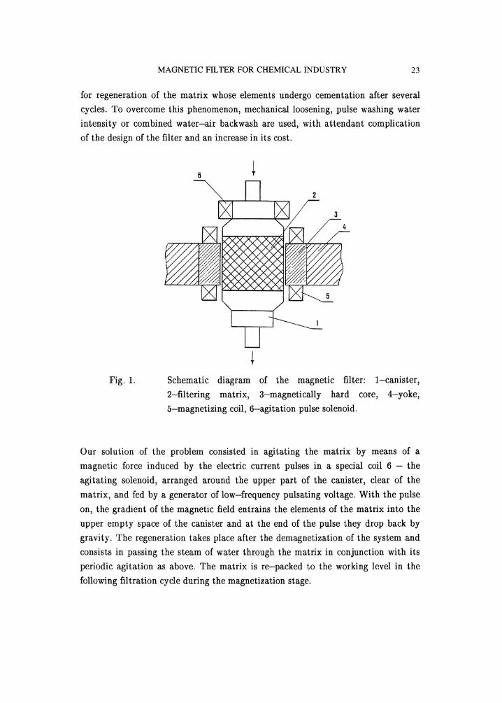
Schematic diagram of the magnetic filter: 1-canister,
2-filtering matrix, 3-magnetically hard core, 4-yoke,
5-magnetizing coil, 6-agitation pulse solenoid.
Our solution of the problem consisted in agitating the matrix by means of a
magnetic force induced by the electric current pulses in a special coil 6 the
agitating solenoid, arranged around the upper part of the canister, clear of the
matrix, and fed by a generator of low-frequency pulsating voltage. With the pulse
on, the gradient of the magnetic field entrains the elements of the matrix into the
upper empty space of the canister and at the end of the pulse they drop back by
gravity. The regeneration takes place after the demagnetization of the system and
consists in passing the steam of water through the matrix in conjunction with its
periodic agitation as above. The matrix is re-packed to the working level in the
following filtration cycle during the magnetization stage.
24 I. SPEVAKOVA ET AL.
As the upper layers of the matrix are agitated more efficiently than the lower ones,the effect on the backwash is more pronounced when the filtration proceeds in the
downward direction (the upper layers being more intensively dogged) and the
backwash proceeds upwards. Such a geometry is not always easy to realize but it is
optimum for a ball matrix. When the matrix consists of oblong shavings, the
solenoid can be located at the bottom of the separator and its downward-directed
magnetic force makes for lengthwise vertical arrangement of the elements. In such
a case the filtration and the backwash can proceed upwards and downwards,respectively.
OPEtLTING CHARACTERISTICS OF THE FILTER
In the laboratory model the Fe-Ni-A1-Co alloy with residual magnetic induction
of Bt 11 kG and coercive force He_450 Oe was used as the core material. The
spacing of the poles was 120 mm, the magnetic field induced in the space between
the poles, with the matrix absent, was 500 Oe. The maximum dimensions of the
filter, including the yoke, were 0.4 x 0.4 x 0.7 m and its mass, including the
matrix, was less than 100 kg.
The material variants of the matrix were the balls with diameter d 4.0 mm,made of ordinary steel (type ShKhl5) and the shavings of stainless magneticallysoft steel (40Kh13). The magnetic field induction achieved with these variants (asmeasured in 15 mm slit gap) are shown in Table IV, column 3. Both steel elements
were magnetically soft and could be magnetized in the field H 10 kOe up to
B 13 kG (for porous media [12], as against B 22 kG for non-porous
substances). The differences in the magnetic induction values, as seen in Table IVare mostly attributable to differences in porosity, depending on the shape and
dimensions of the shavings (packing values up to T 0.55 can be reached owing to
their disintegration). With ball elements the packing does not depend on their
diameter.
It can be seen that substantially higher field can be achieved through increased
packing but it is not always useful. For sufficiently large ferromagnetic particles it
can be preferable to increase the loading capacity of the matrix and the duration of

MAGNETIC FILTER FOR CHEMICAL INDUSTRY 25
the cycle. Thus the possibility of varying the porosity is a great advantage of the
shavings apart from their low cost as a scrap material.
It is also noteworthy that the magnetic induction in the pores of the balls made of
non-stainless steel (because of price consideration) decreases after prolongedexploitation because of the formation of a nonmagnetic oxide film on the ball
surfaces. The can be rectified, for instance, by pre---coating the balls with a nickel
ferromagnetic film.
Table IV. Magnetic field induction generated in the separator with
different matrices
Mattix Pack ing
Induction in
15 mm slit gap, Gs
Induction at
HoT 2 kOe [12]
Steel balls
(ShKhl5)
Stainless steel
shavings (40Kh13)
0.6 9100 6700
0.33 6600 5500
0.23 5200 4200
For the electromagnetic filters used in industry for the removal of magneticimpurities from liquids and gases [12], the level of electric current corresponding to
the magnetizing field of H_
10 kOe is impractical as the rate of increase of the
magnetic induction drops steeply with an increase of the external magnetic field,and the H
_1 to 2 kOe range can be considered as optimum. The magnetic
induction corresponding to this optimum field in porous matrices of the same
material and packing (again according to [12]) is listed in the right-hand column
of Table IV and it can be seen to be substantially lower.
Stronger field is important for filtration of small and weakly magnetic particles
and its advantage is demonstrated by our results given in Table V, for the ball
matrix and a suspension of magnetite.

26
Table V.
I. SPEVAKOVA ET AL.
The dependence of the quality of the filtrate on the magneticfield induction in the matrix
Strength of
magnetizing pulse, V
Induct ion in
15 rsn slit gap, Gs
Filtrate concentration,
mg/l
400 9100 1.5
240 4800 8.2
180 2500 76
The magnetic field was varied through the strength of the magnetizing pulse.
Magnetite with a large fraction of small particles was separated from a suspension
with initial concentration 1 g/t with the filtration rate of 125 m/h. Comparison
with granulometric composition of the magnetite powder (Table I) shows that the
optimum filtrate concentration under the strongest magnetization of the core was
obtained with particles up tO,the minimum size of approximately 1 #m.
The energy consumption of our filter is 2 Wh for a 30 minute cycle (4 pulses per
hour). Simple calculation shows that this consumption level is about 500 times
lower than that of a direct current coil generating the magnetic field of 2 kOe in
the space of the same volume. Thus, with a magnetically hard core serving as poles
of a system with closed magnetic circuit, the efficiency of the filtration process can
be improved at reduced energy consumption.
The advantage of the proposed method of regeneration was confirmed by our
experiment (Figure 2), in which the backwash was performed either with or
without agitation (curves 1 and 2, respectively). In both cases the matrix was of
the ball type and the material removed was magnetite. The filtration yield was
6% of the matrix by weight, the rates of filtration and backwash were 125 m/h and
200 m/h, respectively. It can be seen that with the same amount of washing water
the backwash efficiency under agitation was increased by 30 to 40%, reaching
nearly 100%. Variation of the agitation frequency in the 0.5 to 1.0 Hz interval did
not produce significant changes.

MAGNETIC FILTER FOR CHEMICAL INDUSTRY 27
It should be noted that considerable improvement of the matrix regeneration is
achieved by the adjustment of the pH of the washing water [13]. This procedure is
efficient for magnetic filtration of waste water but may not be acceptable for
technological solutions of high-purity requirement.
100
75-
25-
5::=::
6 12 18 24Amount of washing water,
Figure 2. The effect of agitation on the backwash: 1 with agitation,2 without agitation
THE CHARACTERISTICS OF THE FILTRATION
Sedimentation tests and microscopic observations under the magnetic field showed
that Raney nickel powder used in the study contained a lighter non-magneticfraction (unleached aluminium). This ruled out the evaluation of the quality of the
filtrate (the amount of magnetic particles that were not captured) by turbiditymeasurements. An alternative solution is X-ray radiography of sediments obtained
by passing the magnetic filtrate through a paper filter. This expensive method,however, failed to yield sufficient information, and, subsequently, the study was
carried out using a series of artificial suspensions of magnetite.

28 I. SPEVAKOVA ET AL.
The ball matrix proved to be uneconomical for highly concentrated (> 1
suspensions because of the attendant strong clogging (of the silt-deposition type).By contrast, in the case of the more porous shaving matrix the clogging effect was
moderate and silting-free, and a similar result was obtained with the ball matrix
after separation of a heavy fraction from the magnetite suspension by elutriation.
Figure 3 shows the turbidity of the filtrate versus the filtration rate, obtained for
the 1 g/i suspension. All data, according to the granulometric composition,
correspond the particles up to the minimum size of approximately 1 #m. Turbiditycan be seen to increase with the initial concentration as a result of the increase in
uncaptured submicron particles. In the case of Raney nickel, no nickel crystallites
above 1 #m were observed in the X-ray photographs of sediments after the
filtration through the matrix of the shavings of both porosities, at rates below
150 m/h.
= 1"2 ::::::.....::io ..........=E 2 :::::.........
0 50 1 O0 150 200Filtration rate, m/h
Figure 3. The concentration of magnetite in the filtrate versus filtration
rate for different types of matrix elements: 1 -steel balls
with 7- 0.6, 2 -stainless steel shavings with T 0.23. The
initial concentration 1 g/i.
The initially established filtration rate drops as the matrix loading increases
(Figure 4): the lower the porosity, the steeper the drop. For the ball matrix ofT 0.6, the curve corresponds to that for the light fraction. For the matrix of the
shavings, no significant changes were observed after the removal of heavy fraction.
The quality of the filtrate improves slightly with the increase of the matrix loading
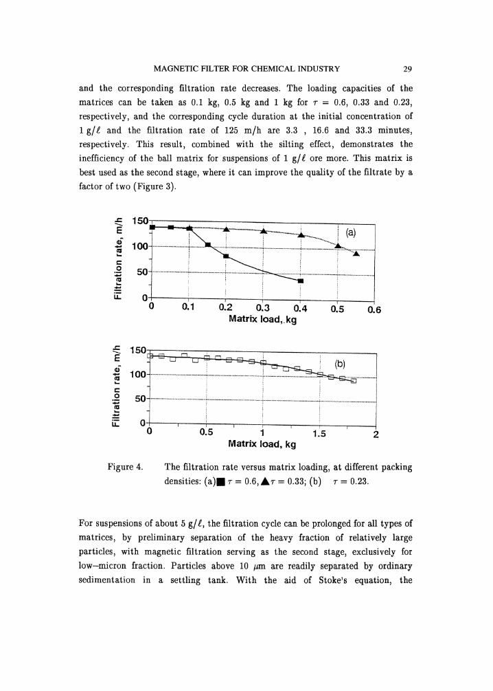
MAGNETIC FILTER FOR CHEMICAL INDUSTRY 29
and the corresponding filtration rate decreases. The loading capacities of the
matrices can be taken as 0.1 kg, 0.5 kg and 1 kg for 7-= 0.6, 0.33 and 0.23,respectively, and the corresponding cycle duration at the initial concentration of
1 g/i and the filtration rate of 125 m/h are 3.3 16.6 and 33.3 minutes,
respectively. This result, combined with the silting effect, demonstrates the
inefficiency of the ball matrix for suspensions of 1 g/i ore more. This matrix is
best used as the second stage, where it can improve the quality of the filtrate by a
factor of two (Figure 3).
150,
100 ! ,.,,.2 50
0 0.1 0.2 0.3 0.4 0.5 0.6MatrN load,.kg
.c: 150
m uu
._.o 50
0 0.5 1 1.5 2Matrix load, kg
Figure 4. The filtration rate versus matrix loading, at different packingdensities: (a)B T 0.6,,&7- 0.33; (b) T 0.23.
For suspensions of about 5 g/l, the filtration cycle can be prolonged for all types of
matrices, by preliminary separation of the heavy fraction of relatively largeparticles, with magnetic filtration serving as the second stage, exclusively forlow-micron fraction. Particles above 10 #m are readily separated by ordinarysedimentation in a settling tank. With the aid of Stoke’s equation, the
30 I. SPEVAKOVA ET AL.
sedimentation rate of 10 #m Raney nickel in water, density 4.5 g/cm3, is found to
be as high as 12.6 m/h (for heavier particles or substances with density and
viscosity less than those of water, it is even higher). After the separation of the
+ 10 #m fraction, the initial concentration, according to the granulometriccomposition, drops by a factor of 10 and the cycle is prolonged proportionately.
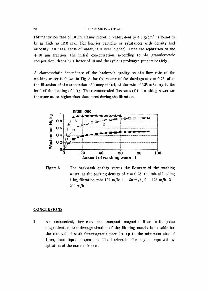
A characteristic dependence of the backwash quality on the flow rate of the
washing water is shown in Fig. 5, for the matrix of the shavings of 7- 0.23, after
the filtration of the suspension of Raney nickel, at the rate of 125 m/h, up to the
level of the loading of 1 kg. The recommended flowrates of the washing water are
the same as, or higher than those used during the filtration.
Initial loadcn 1 ...,..,--,--,--,-,.--,--,--,--,
o.8 /....3 ....,,...""""’"""z I f " i" 0.6, ’ =
o.::, 70 20 4O 60 80 100
Amount of washing water,
Figure 5. The backwash quality versus the flowrate of the washing
water, at the packing density of T 0.23, the initial loading1 kg, filtration rate 125 m/h: 1 50 m/h, 2 125 m/h, 3
200 m/h.
CONCLUSIONS
An economical, low--cost and compact magnetic filter with pulse
magnetization and demagnetization of the filtering matrix is suitable for
the removal of weak ferromagnetic particles up to the minimum size of1 #m, from liquid suspensions. The backwash efficiency is improved byagitation of the matrix elements.

MAGNETIC FILTER FOR CHEMICAL INDUSTRY 31
The yield of the laboratory filter at the filtration rate of 150 m/h, ensuringthe removal of low-micron particles, was 0.6 l/s, subject to the quality ofthe material available for preparation of the cores serving as poles of the
magnetic system. With stronger magnetic materials [14], the yield can be
increased.
In catalytic processes involving magnetically active elements, the magneticfilter can be used both in the final stage for extraction of heterogeneouscatalyst particles from a liquor and in the preliminary stage for separation
of catalytically active magnetic particles from inactive nonmagnetics
introduced during the preparation process of the catalyst (as is the case of
Raney nickel).
ACKNOWLEDGMENT
The authors wish to thank Professor Israel Lin for his helpful discussions and
valuable remarks.
REFERENCES
io Kirk-Othmer: Encyclopedia of Chemical Technology J. Wiley Interscience,1979
Q. Shuncherg et al.: In: Proc.Materials Science of Tungsten,Pergamon Press, 1989, p. 1187
First Internatl. Conf. Metallurgy andTitanium, Rare Earths and Antimony,
J. Yingtai et al.: Ibid., p. 366
T.A. Malinovskaya et al.: Separation of Suspensions in Chemical Industry,(in Russian), Khimiya, Moscow 1983
A.V. Sandulyak: Magnetic Filtration Purification of Liquids and Gases (inRussian), Khimiya, Moscow 1988
R.R. Birrs and M.R. Parker: In: Progr. Filtrat. Separ. 2 (1981), 171

32 I. SPEVAKOVA ET AL.
10.
11.
12.
13.
14.
G.R. Gillespic and D. Goodfellow: Chem. Eng. Progress 70 (1974), 81
G.M. Whitesides et al.: Ind. Eng. Chem., Process Des. Dev. 15 (1976), 226
R.M. Bozorth: Ferromagnetism, Van Nostrand, New York 1951
G.A. Martin and P. Fouilloux: J. Catalysis 38 (1975), 231
Tables of Physical Values,(in Russian), Atomizdat, Moscow 1976
A.V. Sandulyak and V.I. Grashchenko: ElectromagneticFilters-Precipitators (in Russian), Vischa Shkola, L’vov 1982
J. Svoboda and I.J. Corrans: IEEE Trans. Mag. MA G-21 (1985), 53
Annon.: Hitachi Ltd. Development of a new ferromagnet. Mag. Electr.Sep. 3 (1991), 57
Irena Spevakova graduated from the Kharkov State University in 1971 with theM.Sc. degree in physics and joined the Kirensky Institute of Physics, Krasnoyarsk,Russia, where she was engaged in research into magnetic properties oflow-dimensional magnetics. She obtained her Ph.d. degree in physics of magneticphenomena in 1980. Subsequent work in the Kharkov Municipal Research Institutewas concerned with the development of technological processes and equipmentbased on magnetic separation as applied to the purification and recycling ofdomestic and industrial waste waters and technological liquors. At present, she isworking at the Technion, Haifa, Israel. Her research interests include the use ofmagnetic technology and minerals for environmental protection and magnetictreatment of aqueous solutions for the application in industry and agriculture.
Keywords: magnetic filter, heterogeneous catalyst, Raney nickel, magnetite
![ReviewArticle - Hindawi Publishing Corporationdownloads.hindawi.com/journals/cjgh/2018/6150861.pdfCanadianJournalofGastroenterologyandHepatology .; %CI: .-., p = . ) []. Lastly, in](https://img.pdfslide.net/doc/110x75/5fd365b36bdb6805366effb8/reviewarticle-hindawi-publishing-canadianjournalofgastroenterologyandhepatology.jpg)


![Research Letter - Hindawi Publishing Corporationdownloads.hindawi.com/journals/bri/2009/251731.pdf · [7]. Uronic acid was determined by the carbazole method using glucuronolactone](https://img.pdfslide.net/doc/110x75/5e788a5b422b233a6c38924e/research-letter-hindawi-publishing-7-uronic-acid-was-determined-by-the-carbazole.jpg)


![ReviewArticle - Hindawi Publishing Corporationdownloads.hindawi.com/journals/bmri/2011/195483.pdf · dial hibernation, as originally described by Rahimtoola [13], was thought to represent](https://img.pdfslide.net/doc/110x75/5f11972e39c67b61447ebadb/reviewarticle-hindawi-publishing-dial-hibernation-as-originally-described-by.jpg)


![Review Article - Hindawi Publishing Corporationdownloads.hindawi.com/journals/ijd/2010/432767.pdf · to use the term dental caries [37]. The common thought was that caries was the](https://img.pdfslide.net/doc/110x75/5eb4e949016619432c08a9a3/review-article-hindawi-publishing-to-use-the-term-dental-caries-37-the-common.jpg)