Embed Size (px)
Citation preview
Surgical Technique
Sports MedJoint Spine
ULTIMATE VERSATILITY IN ONE SYSTEM

M.U.S.T.® Surgical Technique
2

3
INDEX1. INTRODUCTION 4
1.1 Indications 51.2 Contraindications 51.3 Pre-operative planning 51.4 Surgical approach 5
2. PEDICLE PREPARATION 6
3. POLYAXIAL SCREW INSERTION 83.1 Polyaxialscrewfixation 83.2 Head adjusting 9
4. ROD CONTOURING AND INSERTION 10
5. ROD REDUCTION TECHNIQUES 105.1 Reduction with rod fork 105.2 Reduction with 1-step reducer 115.3 Reduction with 2-steps reducer 125.4 Reduction with the locking tower 135.5 Reduction with the short reducer 13
6. COMPRESSION OR DISTRACTION 156.1 Theory and applications 156.2 Distraction 156.3 Compression 16
7. IN SITU BENDING 16
8. TIGHTENING 178.1 Temporarysetscrewtightening 178.2 Finalsetscrewtightening 17
9. CROSS CONNECTOR 189.1 Rod caliper 20
10. HOOKS 2110.1 Pedicle hook placement 2110.2 Hook placement in the lamina/ transverse process 22
11. LATERAL CONNECTORS 24
12. ROD-TO-ROD CONNECTORS 2512.1 Rod-to-rod connectors positioning 25
13. IMPLANTS NOMENCLATURE 2613.1 Sterile single package 26
M.U.S.T.® Surgical Technique
4
1. INTRODUCTION
1.
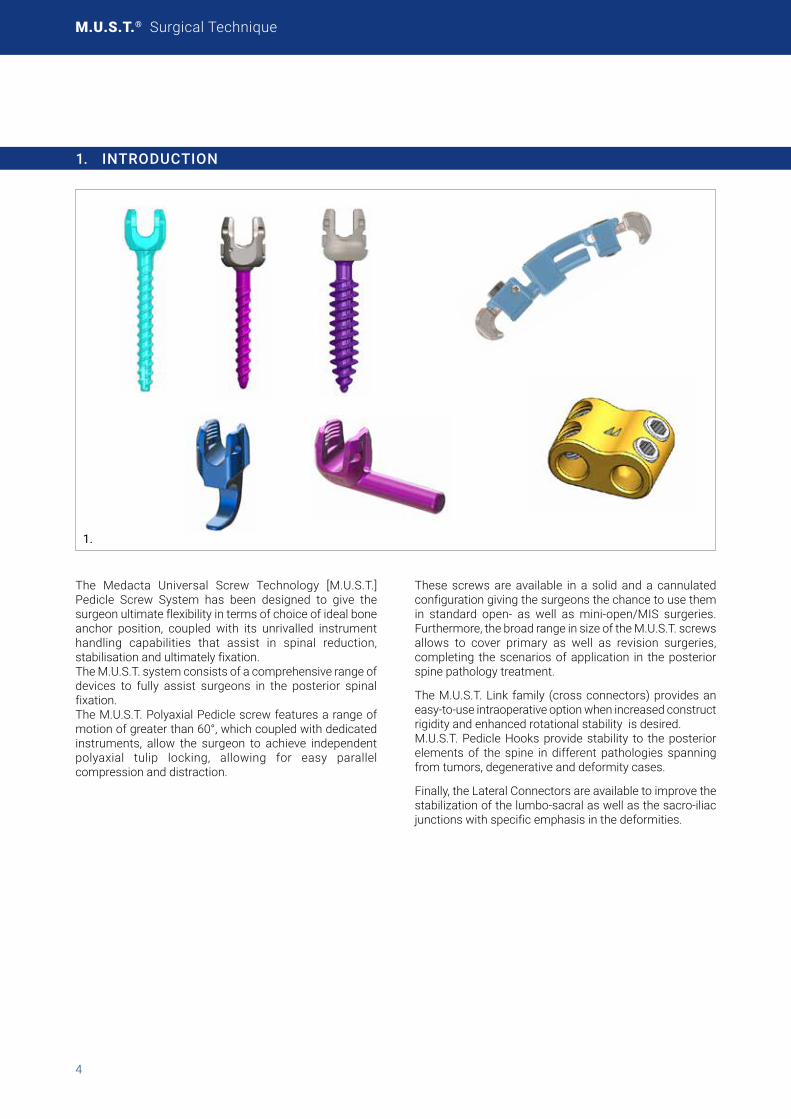
The Medacta Universal Screw Technology [M.U.S.T.] Pedicle Screw System has been designed to give the surgeon ultimate flexibility in terms of choice of ideal bone anchor position, coupled with its unrivalled instrument handling capabilities that assist in spinal reduction, stabilisation and ultimately fixation. The M.U.S.T. system consists of a comprehensive range of devices to fully assist surgeons in the posterior spinal fixation. The M.U.S.T. Polyaxial Pedicle screw features a range of motion of greater than 60°, which coupled with dedicated instruments, allow the surgeon to achieve independent polyaxial tulip locking, allowing for easy parallel compression and distraction.
These screws are available in a solid and a cannulated configuration giving the surgeons the chance to use them in standard open- as well as mini-open/MIS surgeries. Furthermore,thebroadrangeinsizeoftheM.U.S.T.screwsallows to cover primary as well as revision surgeries, completing the scenarios of application in the posterior spine pathology treatment.
The M.U.S.T. Link family (cross connectors) provides an easy-to-use intraoperative option when increased construct rigidity and enhanced rotational stability is desired. M.U.S.T. Pedicle Hooks provide stability to the posterior elements of the spine in different pathologies spanning from tumors, degenerative and deformity cases.
Finally,theLateralConnectorsareavailabletoimprovethestabilizationofthelumbo-sacralaswellasthesacro-iliacjunctions with specific emphasis in the deformities.

5
1.1 INDICATIONS
The M.U.S.T. Pedicle Screw System is intended for posterior non-cervical pedicle fixation (T1-S2/ilium) or anterolateral fixation(T8-L5).Thesedevicesareindicatedasanadjunctto fusion for all of the following indications: degenerative disc disease (defined as back pain of discogenic origin with degeneration of the disc confirmed by history and radiographic studies); spondylolisthesis; trauma (i.e., fracture or dislocation); spinal stenosis; curvatures (i.e., scoliosis, kyphosis, and/or lordosis); tumor; pseudoarthrosis and failed previous fusion in skeletally mature patients.
When used for posterior non-cervical pedicle screw fixation in pediatric patients, the M.U.S.T. implants are indicated as an adjunct to fusion to treat adolescent idiopathic scoliosis. The system is intended to be used with autograft and/or allograft. Pediatric applications are limited to a posterior approach.
1.2 CONTRAINDICATIONS
The use of the M.U.S.T. Pedicle Screw System is contraindicated in the following cases:
• Active infectious process or significant risk of infection (immunocompromised hosts).
• Signs of local inflammation.
• Feverorleukocytosis.• Morbid obesity.
• Mental illness.
• Grossly distorted anatomy caused by congenital abnormalities.
• Any other medical or surgical condition which would preclude the potential benefit of spinal implant surgery, such as the presence of congenital abnormalities, elevation of sedimentation rate unexplained by other diseases, elevation of white blood count (WBC), or a marked left shift in the WBC differential count.
• Suspected or documented metal allergy or intolerance.
• Any case not needing a bone graft and fusion.
• Any case where the implant components selected for use would be too large or too small to achieve a successful result.
• Any patient having inadequate tissue coverage over the operative site or inadequate bone stock or quality.
• Anypatientinwhichimplantutilizationwouldinterferewith anatomical structures or expected physiological performance.
• Any patient unwilling to follow postoperative instructions.
• Any case not described in the indications.
Although not absolutely contraindicated, conditions to be considered as potential factors for not using this device include severe bone resorption, osteomalacia, and severe osteoporosis.
1.3 PRE-OPERATIVE PLANNING
The review of MRI and/or CT based imaging to template anddeterminethetype/sizeoftheimplantstobeusedtomatch the patient’s anatomy is a critical step in the pre-operative planning before each surgery.
1.4 SURGICAL APPROACH
The M.U.S.T. Pedicle Screw System is designed with the focus on spinal fixation. The choice of the surgical approach is at the discretion of the surgeon.
The different Posterior approaches are Midline, Wiltse, Mini-Open as well as Percutaneous.
The different Anterior/Lateral approaches are Laparoscopic, Open or Mini-Open. Surgeons would use the retroperitoneal or the trans-psoas technique.
The construct is assembled in the same way as the posterior approach, the screws however are placed directly in the vertebrae, instead of the pedicles.

M.U.S.T.® Surgical Technique
6
2. PEDICLE PREPARATION
Locate the pedicles and perforate the outer cortex with the Pedicle Awl.
Use the Pedicle Probe to open the pedicle canal. The 10mm incremental markings on the probe shaft provide an initial visual indication of the pedicle canal depth.
2.
UsetheBallTipFeelertocheckthemedial,lateral,superior,inferior and ventral walls of the pedicle for possible violation.
3.
A Depth Gauge is available to check the canal depth and to help determining the length of the pedicle screw.
4.
The M.U.S.T. bone screws are self-tapping. A variety of Taps of different diameters are available and may be utilizedatthediscretionofthesurgeon.Totapthepedicle,use the selected Tap with the Quick Connector Ratcheting T-Handle.
WARNING Before inserting pedicle screws larger than 7mm indiameter, is mandatory to tap the pedicles. In case of sclerotic bone or any other reason that can cause high resistance during screw insertion apply the same procedure for all the other diameters. Please note that the taps are 0.5mmundersized.
5.
7
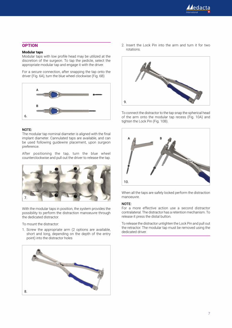
OPTIONModular taps Modulartapswithlowprofileheadmaybeutilizedatthediscretion of the surgeon. To tap the pedicle, select the appropriate modular tap and engage it with the driver.
Forasecureconnection,aftersnappingthetapontothedriver(Fig.6A),turnthebluewheelclockwise(Fig.6B)
A
B
6.
NOTE:The modular tap nominal diameter is aligned with the final implant diameter. Cannulated taps are available, and can be used following guidewire placement, upon surgeon preference.
After positioning the tap, turn the blue wheel counterclockwise and pull out the driver to release the tap.
7.
With the modular taps in position, the system provides the possibility to perform the distraction manoeuvre through the dedicated distractor.
To mount the distractor:1. Screw the appropriate arm (2 options are available,
short and long, depending on the depth of the entry point) into the distractor holes
8.
2. Insert the Lock Pin into the arm and turn it for two rotations.
9.
To connect the distractor to the tap snap the spherical head of the armonto themodular tap recess (Fig. 10A) andtightentheLockPin(Fig.10B).
A B
10.
When all the taps are safely locked perform the distraction manoeuvre.
NOTE:For a more effective action use a second distractorcontralateral. The distractor has a retention mechanism. To release it press the distal button.
To release the distractor untighten the Lock Pin and pull out the retractor. The modular tap must be removed using the dedicated driver.

M.U.S.T.® Surgical Technique
8
3. POLYAXIAL SCREW INSERTION
3.1 POLYAXIAL SCREW FIXATION
After the pedicle canal has been prepared and possibly tapped, the surgeon can plan for the M.U.S.T. screw insertion.Thesizeofthescrewtoimplantdependsonthediameter and the length of the prepared pedicle canal, in relation to the vertebral anatomy. The M.U.S.T. screws can be inserted and fixed with the Polyaxial Pedicle Screwdriver specifically designed to easily align the screw in order to avoid toggling. The blue central handle of the screwdriver is free to rotate, and allows the surgeon to achieve a stable grip on the screwdriver with the non-dominant hand, while inserting the screw with the dominant hand.
11.
Start with attaching the Polyaxial Pedicle Screwdriver to the specific handle.
A Spherical, Straight or T-shaped Quick Connecting Ratcheting Handle is available in our instrument range to give the surgeon a broad range of choice.
Insert the screwdriver tip into the screw head, locking it in the correct alignment as indicated in the figures here below.
12.
NOTE: When using polyaxial screws the correct pedicle screw/poly-axial screwdriver coupling may be reached after a slight rotation and re-alignment of the screw body. When using the monoaxial screws the correct orientation
over the Polyaxial ScrewDriver is already ensured by a “self-alignment” design.
Tighten the head of the pedicle screw to the Polyaxial Screwdriver using the proximal gear, firmly turn it clockwise until the screw is fully tightened. Once secured, it is no longer possible for the screw to move as it is fully engaged with the Polyaxial Pedicle Screwdriver.
13.
Insert the screw into the prepared pedicle canal by turning the Handle clockwise. The screws have a dual lead thread allowing for faster screw insertion.
14.
After satisfactory fixation of the screw you can easily remove the screwdriver from the pedicle screw head by turning the proximal gear counter-clockwise.

9
Proximal Gear
15.
OPTION It is possible to use the Bone Screwdriver that does not lock the pedicle screw head (tulip) rotation. The use of the Bone Screwdriver is suggested for further screw advancement, if needed, after the insertion made with the Polyaxial Pedicle Screwdriver.
OPTION Cannulated screws are available, and can be used following guidewire placement, upon surgeon preference.
3.2 HEAD ADJUSTING
After the insertion of the polyaxial pedicle screw, check the orientation of the head and if needed correct it with the Head Adjuster.
16.
The coupling of the Head Adjuster with the polyaxial pedicle screw facilitates screw head adjustment of the inclination in each possible direction.
17.
With the monoaxial pedicle screw, the head orientation can be adjusted with the Head Adjuster allowing for further forward/backward screw advancement.

M.U.S.T.® Surgical Technique
10
4. ROD CONTOURING AND INSERTION
All rods are available both in Titanium as well as in CoCr alloy with variable lengths, and in both straight and pre-bent forms.
The surgeon can select the rod that most closely approximates the desired saggital contour. The pre-bent Trial Rods (35-100mm) can be used to facilitate the template process.
If further contouring of the rods is required to achieve the desired alignment, it is also possible to bend the rods with thededicatedbendinginstruments.Forlongerconstructs,a malleable rod (450mm) is available and can be used to template the desired contouring.
18.
CAUTION UseonlytheFrenchRodBenderavailablewiththestandardM.U.S.T. instrumentation to bend the rods. Never bend the rod more than one time. Repeated bending may result in a weakening of the rod and possible rod fracture.
Use the rod insertion forceps to position the rod into the selected pedicle screw heads.
CAUTION When possible, position the rod with the laser marking facing posteriorly to help the correct alignment within the screw heads.
5. ROD REDUCTION TECHNIQUES
The rod must be completely seated within the pedicle screw heads to allow for final rod manipulation and construct positioning. There are 4 different instrumentation options that can be used to facilitate rod reduction:
• RodFork• 1-Step Reducer
• 2-Steps Reducer
• Locking Tower
These instruments can aid with the temporary tightening of the set screw before final check of the construct and the final set screw tightening.
CAUTION Always place the reduction instrument where the rod is higher to have a more effective rod reduction.
5.1 REDUCTION WITH ROD FORK
Place the Rod Fork into the head’s reduction sockets. Use only the socket opposite to the side of the reduction to have a better grip on the tulip. To reduce the rod, rock the RodForkuntiltherodisfullyseatedwithinthetulip.
19.
11
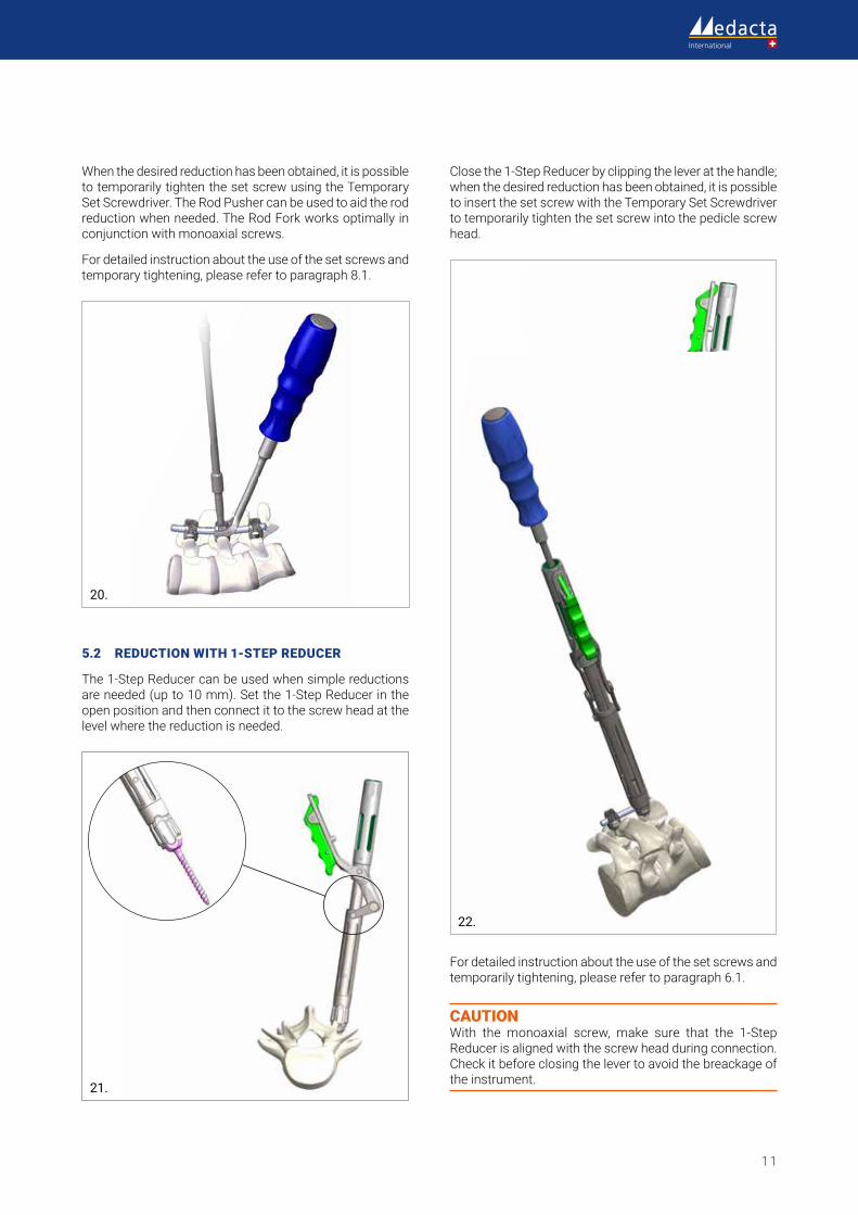
When the desired reduction has been obtained, it is possible to temporarily tighten the set screw using the Temporary Set Screwdriver. The Rod Pusher can be used to aid the rod reductionwhenneeded.TheRodForkworksoptimallyinconjunction with monoaxial screws.
Fordetailedinstructionabouttheuseofthesetscrewsandtemporarytightening,pleaserefertoparagraph8.1.
20.
5.2 REDUCTION WITH 1-STEP REDUCER
The 1-Step Reducer can be used when simple reductions are needed (up to 10 mm). Set the 1-Step Reducer in the open position and then connect it to the screw head at the level where the reduction is needed.
21.
Close the 1-Step Reducer by clipping the lever at the handle; when the desired reduction has been obtained, it is possible to insert the set screw with the Temporary Set Screwdriver to temporarily tighten the set screw into the pedicle screw head.
22.
Fordetailedinstructionabouttheuseofthesetscrewsandtemporarily tightening, please refer to paragraph 6.1.
CAUTION With the monoaxial screw, make sure that the 1-Step Reducer is aligned with the screw head during connection. Check it before closing the lever to avoid the breackage of the instrument.

M.U.S.T.® Surgical Technique
12
5.3 REDUCTION WITH 2-STEPS REDUCER
The 2-Steps Reducer can be used when a higher reduction power is needed (up to 35 mm).
23.
Set the 2-Steps Reducer in the open position and then connect it to the screw head at the level where the reduction is needed.
Close the 2-Steps Reducer by clipping the lever at the handle; with the locking sleeve fully locked, insert the Reduction Driver into the 2-Steps Reducer up to the beginning of the thread.To reduce the rod, simply screw the Reduction Driver down through the 2-Steps Reducer.
24.
25.
When the desired reduction has been obtained, it is possible to insert the set screw through with the Temporary Set Screwdriver to temporarily tighten the set screw into the pediclescrewhead.Fordetailedinstructionabouttheuseof the set screws and temporarily tightening, please refer toparagraph8.1
NOTE: The Reduction Driver Handle can be removed allowing to reduce the overall hindrance and help facilitating manipulation especially when the two 2-Steps Reducers are placed in series.
26.
CAUTION With the monoaxial screw, make sure that the 2-Step Reducer is aligned with the screw head during connection.Check it before starting the reduction to avoid the breackage of the instrument.
13
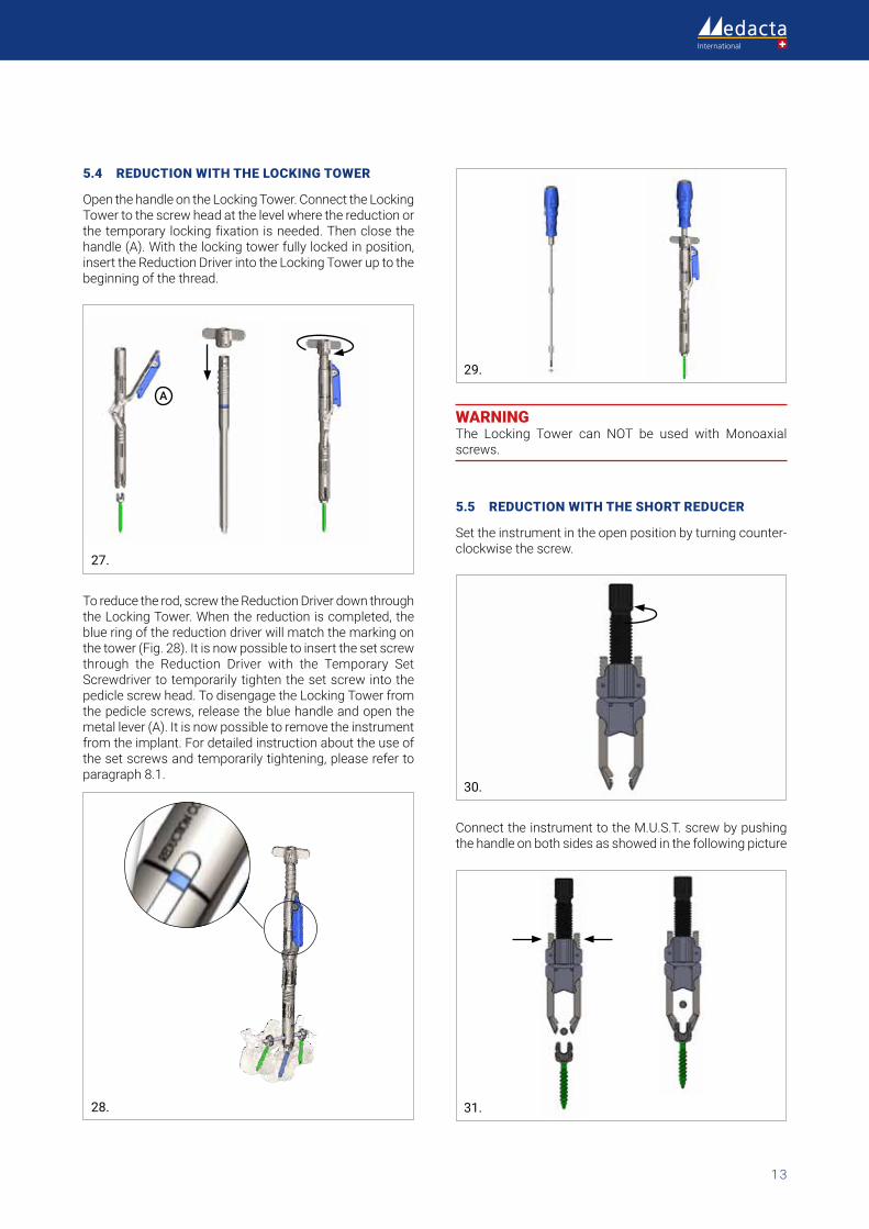
5.4 REDUCTION WITH THE LOCKING TOWER
Open the handle on the Locking Tower. Connect the Locking Tower to the screw head at the level where the reduction or the temporary locking fixation is needed. Then close the handle (A). With the locking tower fully locked in position, insert the Reduction Driver into the Locking Tower up to the beginning of the thread.
A
27.
To reduce the rod, screw the Reduction Driver down through the Locking Tower. When the reduction is completed, the blue ring of the reduction driver will match the marking on thetower(Fig.28).Itisnowpossibletoinsertthesetscrewthrough the Reduction Driver with the Temporary Set Screwdriver to temporarily tighten the set screw into the pedicle screw head. To disengage the Locking Tower from the pedicle screws, release the blue handle and open the metal lever (A). It is now possible to remove the instrument fromtheimplant.Fordetailedinstructionabouttheuseofthe set screws and temporarily tightening, please refer to paragraph8.1.
28.
29.
WARNING The Locking Tower can NOT be used with Monoaxial screws.
5.5 REDUCTION WITH THE SHORT REDUCER
Set the instrument in the open position by turning counter-clockwise the screw.
30.
Connect the instrument to the M.U.S.T. screw by pushing the handle on both sides as showed in the following picture
31.
M.U.S.T.® Surgical Technique
14
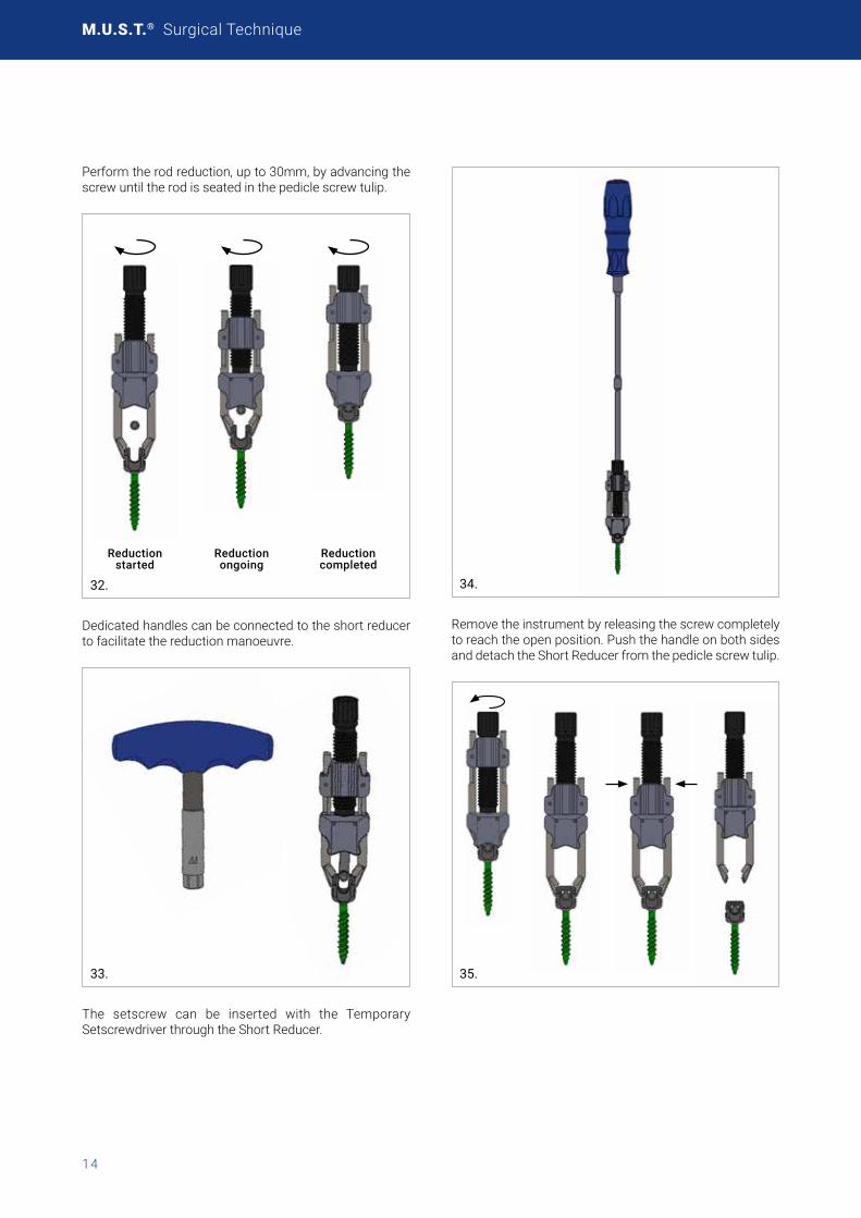
Perform the rod reduction, up to 30mm, by advancing the screw until the rod is seated in the pedicle screw tulip.
Reduction started
Reduction ongoing
Reduction completed
32.
Dedicated handles can be connected to the short reducer to facilitate the reduction manoeuvre.
33.
The setscrew can be inserted with the Temporary Setscrewdriver through the Short Reducer.
34.
Remove the instrument by releasing the screw completely to reach the open position. Push the handle on both sides and detach the Short Reducer from the pedicle screw tulip.
35.
15
6. COMPRESSION OR DISTRACTION
6.1 THEORY AND APPLICATIONS
The M.U.S.T. Pedicle Screw system, provides the possibility to perform both parallel compression and parallel distraction as well as adapt the segmental lordosis using the Locking Tower.
When the polyaxiality of the screw head is locked while one or both tulips are free to slide on the rod, compression or distraction result in a parallel movement of the screw.
36.
Due to the versality of the Locking Tower, it is possible to perform parallel compression or distraction even without having the rod & set screw in place. Parallel distraction without the rod in place may facilitate a more thorough discectomy and improved access to the anterior aspect of the disc, as well as facilitate a more efficient positioning of the cage.
37.
When the screw heads are free to rotate (one or both), compression and distraction result in a modification of the lordosis between the two vertebrae involved.
38.
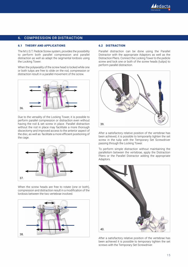
6.2 DISTRACTION
Parallel distraction can be done using the Parallel Distractor with the appropriate Adaptors as well as the Distraction Pliers. Connect the Locking Tower to the pedicle screw and lock one or both of the screw heads (tulips) to perform parallel distraction.
39.
After a satisfactory relative position of the vertebrae has been achieved, it is possible to temporarily tighten the set screw in the tulip with the Temporary Set Screwdriver passing through the Locking Tower.
To perform simple distraction without maintaining the parallelism between the vertebrae, apply the Distraction Pliers or the Parallel Distractor adding the appropriate Adaptors.
40.
After a satisfactory relative position of the vertebrae has been achieved it is possible to temporary tighten the set screws with the Temporary Set Screwdriver.
M.U.S.T.® Surgical Technique
16
6.3 COMPRESSION
Parallel compression can be done using the Parallel. Compressor with the appropriate Adaptors as well as the Compression Pliers. Connect the Locking Tower to the pedicle screw and lock one or both of the screw heads (tulips) to perform parallel compression
41.
After a satisfactory relative position of the vertebrae has been achieved, it is possible to temporarily tighten the set screw in the tulip with the Temporary Set Screwdriver passing through the Locking Tower.
42.
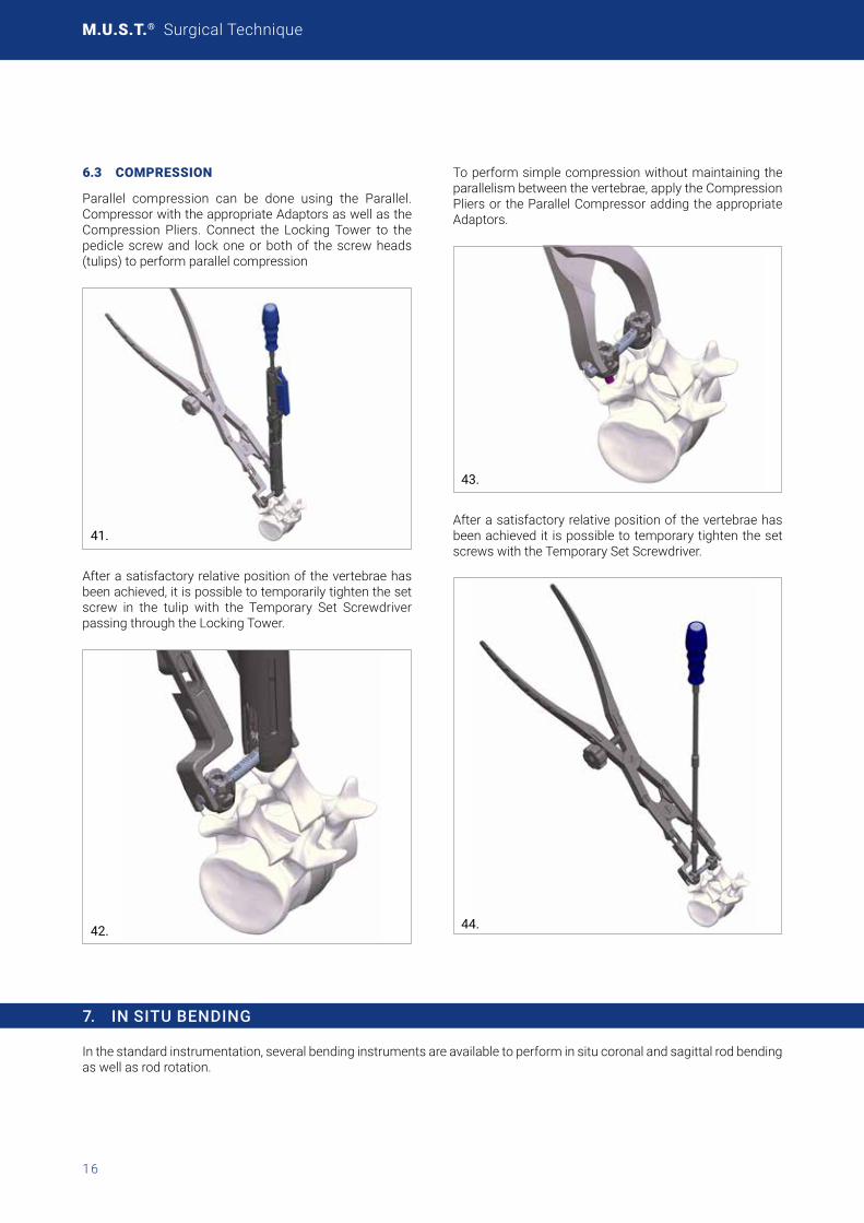
To perform simple compression without maintaining the parallelism between the vertebrae, apply the Compression Pliers or the Parallel Compressor adding the appropriate Adaptors.
43.
After a satisfactory relative position of the vertebrae has been achieved it is possible to temporary tighten the set screws with the Temporary Set Screwdriver.
44.
7. IN SITU BENDING
In the standard instrumentation, several bending instruments are available to perform in situ coronal and sagittal rod bending as well as rod rotation.
17
8. TIGHTENING
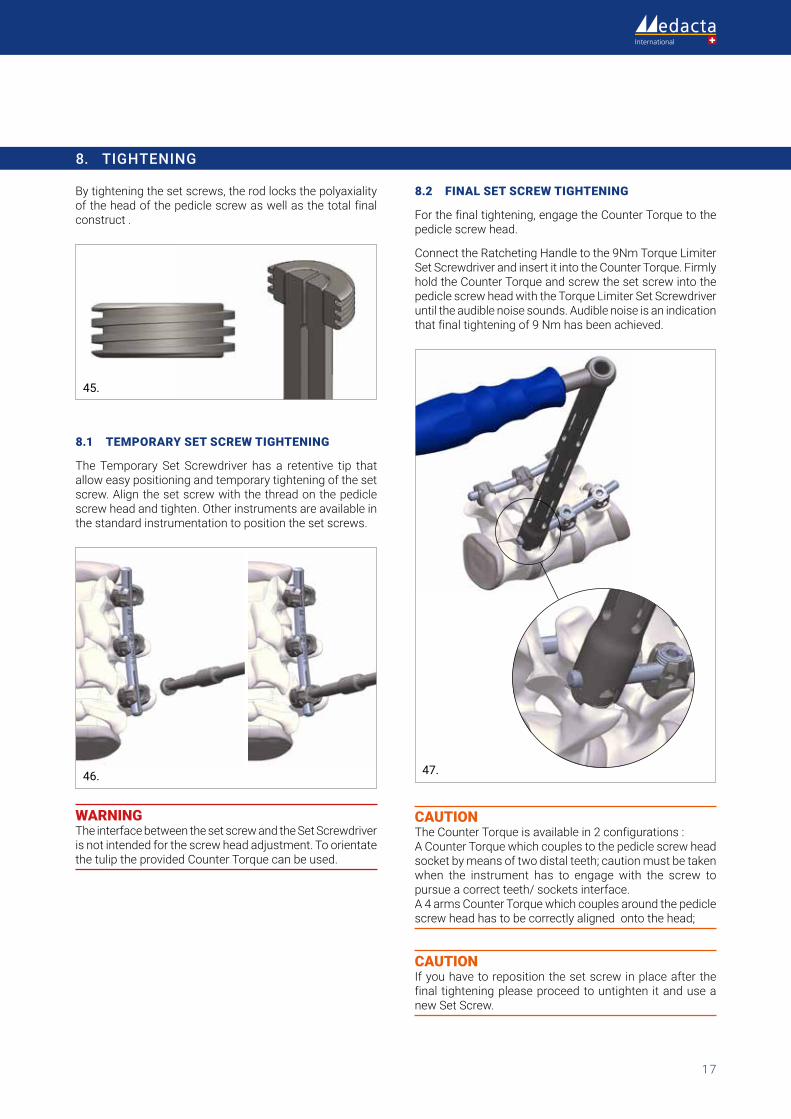
By tightening the set screws, the rod locks the polyaxiality of the head of the pedicle screw as well as the total final construct .
45.
8.1 TEMPORARY SET SCREW TIGHTENING
The Temporary Set Screwdriver has a retentive tip that allow easy positioning and temporary tightening of the set screw. Align the set screw with the thread on the pedicle screw head and tighten. Other instruments are available in the standard instrumentation to position the set screws.
46.
WARNING The interface between the set screw and the Set Screwdriver is not intended for the screw head adjustment. To orientate the tulip the provided Counter Torque can be used.
8.2 FINAL SET SCREW TIGHTENING
Forthefinaltightening,engagetheCounterTorquetothepedicle screw head.
Connect the Ratcheting Handle to the 9Nm Torque Limiter SetScrewdriverandinsertitintotheCounterTorque.Firmlyhold the Counter Torque and screw the set screw into the pedicle screw head with the Torque Limiter Set Screwdriver until the audible noise sounds. Audible noise is an indication that final tightening of 9 Nm has been achieved.
47.
CAUTION The Counter Torque is available in 2 configurations : A Counter Torque which couples to the pedicle screw head socket by means of two distal teeth; caution must be taken when the instrument has to engage with the screw to pursue a correct teeth/ sockets interface. A 4 arms Counter Torque which couples around the pedicle screw head has to be correctly aligned onto the head;
CAUTION If you have to reposition the set screw in place after the final tightening please proceed to untighten it and use a new Set Screw.
M.U.S.T.® Surgical Technique
18
48.
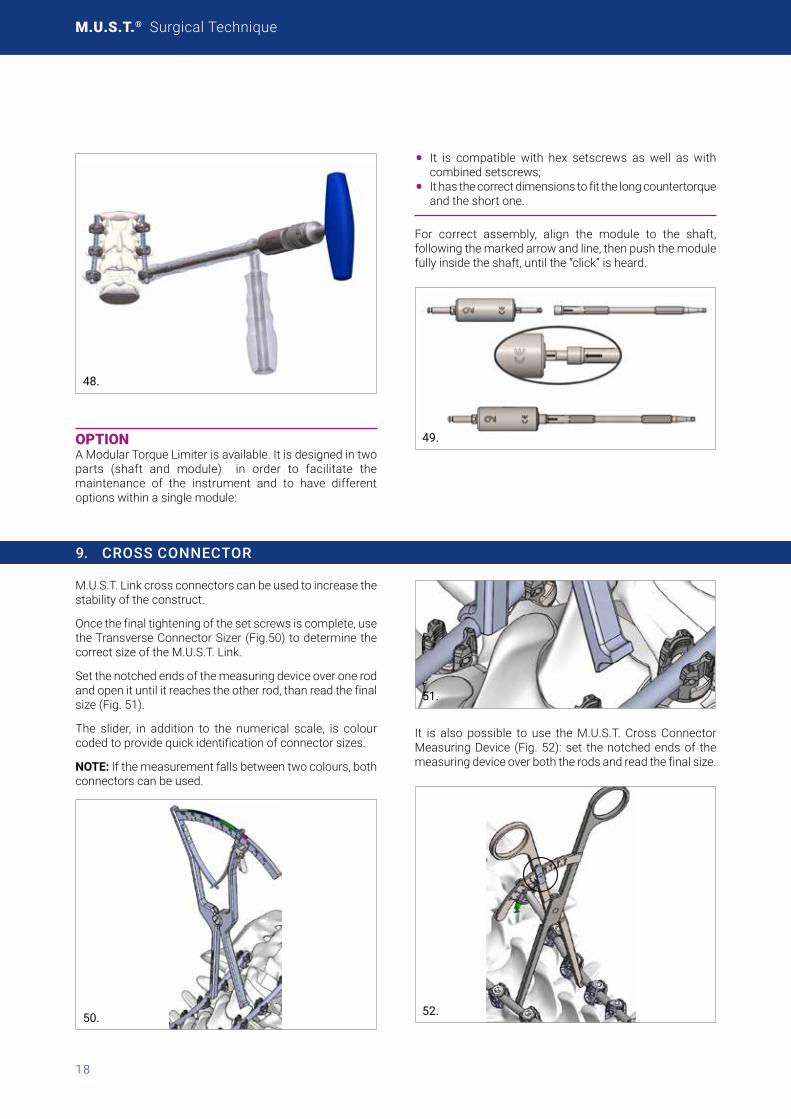
OPTION A Modular Torque Limiter is available. It is designed in two parts (shaft and module) in order to facilitate the maintenance of the instrument and to have different options within a single module:
• It is compatible with hex setscrews as well as with combined setscrews;
• It has the correct dimensions to fit the long countertorque and the short one.
For correct assembly, align the module to the shaft,following the marked arrow and line, then push the module fully inside the shaft, until the “click” is heard.
49.
9. CROSS CONNECTOR
M.U.S.T. Link cross connectors can be used to increase the stability of the construct.
Once the final tightening of the set screws is complete, use theTransverseConnectorSizer(Fig.50)todeterminethecorrectsizeoftheM.U.S.T.Link.
Set the notched ends of the measuring device over one rod and open it until it reaches the other rod, than read the final size(Fig.51).
The slider, in addition to the numerical scale, is colour codedtoprovidequickidentificationofconnectorsizes.
NOTE: If the measurement falls between two colours, both connectors can be used.
50.
51.
It is also possible to use the M.U.S.T. Cross Connector MeasuringDevice (Fig.52):set thenotchedendsof themeasuringdeviceoverboththerodsandreadthefinalsize.
52.

19
NOTE: The table below provides a summary of the correct StraightCross-Connectorsizeselection:
Rod distance Recommendedsize Reference
10-25 20 03.56.402
26-35 30 03.56.403
36-45 40 03.56.404
46-55 50 03.56.405
56-65 60 03.56.406
66-75 70 03.56.407
76-85 80 03.56.408
86-95 90 03.56.409
96-105 100 03.56.410
UsetheRodInsertionForcepstopickuptheappropriateM.U.S.T. Link Cross Connector and snap it onto the rods.
53.
Confirm that the M.U.S.T. Link is correctly connected to the rods.
54.
Forthefinaltightening,engagetheCounterTorquetothepedicle screw head and use the 5.5Nm Torque Limiter Set Screw Driver to fix the Set screw.
55.
M.U.S.T. MC cross connectorAs an alternative to the M.U.S.T Link cross connectors and straight cross connector, there is also the option of the M.U.S.T MC cross connector. This device has been designedwithaminimizedprofileandisintendedforusewithrodsbetween19and40mmin length.Forthefinaltightening use the 5.5Nm Torque limiter set screwdriver to fix the Set Screw.
Two version of the M.U.S.T. MC cross connector are available. In the straight version the hook can tilt ±5°, in the adjustable ±15°.

M.U.S.T.® Surgical Technique
20
56.
9.1 ROD CALIPER
The new Rod Caliper is designed to help the surgeon in choosing the correct rod length:
• The correct rod length
57.
ROD LENGTH MEASUREMENTPlace the Rod Caliper into the screw heads and read (on the side marked with “rod length” – see image below) the optimalsizeofrodtobeimplantedonthemarkedplate.
NOTES:
• The rod caliper shows the optimal size of rod to beimplanted, not the distance between the two pedicle screw heads
• In case of an intermediate rod size measurement,choosethelongerrodsize
• Therodcaliperprovidesanindicationforrodsizeuptoa maximum length of 150mm; rods longer than 150mm can be evaluated by the sum of multiple measurements
58.

21
10. HOOKS
A comprehensive Hook system is available in order to fit the unique anatomy of the posterior elements especially to meet the different needs of patients suffering of scoliosis and other deformities. Several Hook Implants are available and can be used depending from the different anatomical site and up to the required needs:
HOOK TYPE ANATOMICAL PLACEMENT SITE BLADE DIRECTION SPINE REGION
Pedicle Hook Articular Process Thoracic
Extended Body Hook Lamina / Transverse Process Thoracic / Lumbar
Wide Blade Hook Lamina / Transverse Process Thoracic / Lumbar
Angled Hook Lamina Thoracic
Offset Hook Lamina / Transverse Process Thoracic / Lumbar
Narrow Blade Hook Lamina / Transverse Process Thoracic / Lumbar
10.1 PEDICLE HOOK PLACEMENT
Pedicle PreparationUse the Pedicle Elevator to open the facet capsule and locate the pedicle.
59.
Use the chisel to remove a small part of the inferior articular process and ensure a proper seating of the pedicle hook.
WARNING The Pedicle hooks opening must face upwards.
Trial SelectionThe use of the Pedicle Hook Trials is meant to determine theproperimplantsize.UsetheHookForcepstopositionthe Pedicle Hook Trials in place. The Hook Pusher can also beutilizedtofacilitatetheplacement.
60.
M.U.S.T.® Surgical Technique
22
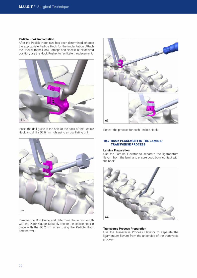
Pedicle Hook ImplantationAfterthePedicleHooksizehasbeendetermined,choosethe appropriate Pedicle Hook for the implantation. Attach theHookwiththeHookForcepsandplaceitinthedesiredposition; use the Hook Pusher to facilitate the placement.
.61.
Insert the drill guide in the hole at the back of the Pedicle Hook and drill a Ø2.0mm hole using an oscillating drill.
62.
Remove the Drill Guide and determine the screw length with the Depth Gauge. Securely anchor the pedicle hook in place with the Ø3.2mm screw using the Pedicle Hook Screwdriver.
63.
Repeat the process for each Pedicle Hook.
10.2 HOOK PLACEMENT IN THE LAMINA/ TRANSVERSE PROCESS
Lamina PreparationUse the Lamina Elevator to separate the ligamentum flavum from the lamina to ensure good bony contact with the hook.
64.
Transverse Process PreparationUse the Transverse Process Elevator to separate the ligamentum flavum from the underside of the transverse process.

23
65.
Hook ImplantationAfter the hook size has been determinedwith theTrialselection, choose the appropriate Hook for the implantation.AttachthehookwiththeHookForcepsandplaceitinthedesired position, either the Lamina or the Transverse process, and use the Hook Pusher to facilitate the placement.
66.
67.
68.
NOTE: Hooks can be placed with either supra- on intra-laminar positioning.
Repeat the process for each Lamina/Transverse Process hook.
In order to perform the following surgical steps please refer to the same technique above described, i.e:
• Rod Contouring and Insertion (Chapter 4)
• Rod Reduction Techniques (Chapter 5)
• Compression and distraction (Chapter 6)
• InsituBending(Chapter7)• Tightening(Chapter8)

M.U.S.T.® Surgical Technique
24
11. LATERAL CONNECTORS
The lateral connectors allow for medial/lateral variability helping to ligning up screws to the rod. These implants can be used for iliac fixation including leveling pelvic obliquity, correcting coronal and sagittal imbalance, and providing rigid fixation to help prevent recurrent deformity.
Lateral Connectors PositioningInstrument the spine with a rod construct down to S1 according to the surgical technique above described.
Select the lateral connector of the appropriate length and insert it into the rod with the opening facing down. Rotate the lateral connector and adjust the vertical shift on the Rod as to engage it with the iliac pedicle screw head.
69.
CAUTION Potential metal fragments have to be removed from the implant to avoid any adverse reaction because of dissimilar metals.
70.
Provisionally tighten the set screw of both the lateral connector and the pedicle screw with the Temporary Set ScrewdriverasdescribedinChapter8.1.
71.
Perform final tightening of the lateral connector as well as theiliacpediclescrewasdescribedinchapter8.2.Repeatthe process for the counter side.
OPTION It is also possible to insert all screws and iliac connectors first, and then apply the rod.

25
12. ROD-TO-ROD CONNECTORS
The rod-to-rod connectors allow for the in-line or parallel connection of two rods according to the surgical need. It is also possible to connect two different rod diameters and to choose between the open or closed profile of the domino connector itself.
12.1 ROD-TO-ROD CONNECTORS POSITIONING
Select the rod-to-rod connector of the appropriate sizeusing the connector inserter and tighten one set screw,using the connector screwdriver, to temporarily secure it to the connector inserter.
72.
Then, using the connector inserter, insert it by sliding it onto the rod that is already in position and lock temporarily the set screws with the connector screwdriver. Slide out the connector inserter, insert the rod to be connected and proceed with the final tightening of the set screws with using the 5.5Nm torque limiter.
73.
If Open connector are used, the same can be inserted on the rod form the side.
74.
When using the In-line connectors it is also possible to inspect the rod final position through the opening on the connector itself (as shown in the picture below).
75.
Where tulip based connector are used, final tightening must be performed using the 9Nm Torque Limiter as this connector is provided with the standard MUST set screws.
76.
77.

M.U.S.T.® Surgical Technique
26
POLYAXIAL PEDICLE SCREWS - SOLID
REFERENCE DIAMETER (mm) LENGTH (mm)
03.50.050
8
20 03.50.051 25 03.50.052 30 03.50.053 35 03.50.054 40 03.50.055 45 03.50.056 50 03.50.057 55 03.50.058 60 03.50.059 65 03.50.060 7003.50.061 7503.50.062 8003.50.063 8503.50.064 90 03.50.065 95 03.50.066 100
03.50.070
9
30 03.50.071 35 03.50.072 40 03.50.073 45 03.50.074 50 03.50.075 55 03.50.076 60 03.50.077 65 03.50.078 7003.50.079 7503.50.080 8003.50.081 8503.50.082 90 03.50.083 95 03.50.084 100
03.50.090
10
30 03.50.091 35 03.50.092 40 03.50.093 45 03.50.094 50 03.50.095 55 03.50.096 60 03.50.097 65 03.50.098 7003.50.099 7503.50.100 8003.50.101 8503.50.102 90 03.50.103 95 03.50.104 100
POLYAXIAL PEDICLE SCREWS - SOLID
REFERENCE1 DIAMETER (mm) LENGTH (mm)
03.50.151
4
20 03.50.152 25 03.50.153 30 03.50.154 35 03.50.155 40 03.50.156 45 03.50.157 50
03.50.001
4,5
20 03.50.002 25 03.50.003 30 03.50.004 35 03.50.005 40 03.50.006 45 03.50.007 50
03.50.008
5
25 03.50.009 30 03.50.010 35 03.50.011 40 03.50.012 45 03.50.013 50
03.50.014
6
25 03.50.015 30 03.50.016 35 03.50.017 40 03.50.018 45 03.50.019 50 03.50.020 55 03.50.021 60 03.50.022 65
03.50.028
7
30 03.50.029 35 03.50.030 40 03.50.031 45 03.50.032 50 03.50.033 55 03.50.034 60 03.50.035 65 03.50.036 7003.50.038 8003.50.040 90
1 includes 1 screw and 1 set screw
13. IMPLANTS NOMENCLATURE
13.1 STERILE SINGLE PACKAGE

27
ENHANCED POLY-AXIAL PEDICLE SCREW - CANNULATED
REFERENCE1 DIAMETER (mm) LENGTH (mm)
03.52.301
4.5
20 03.52.302 25 03.52.303 30 03.52.304 35 03.52.305 40 03.52.306 45 03.52.307 50
03.52.311
5
25 03.52.312 30 03.52.313 35 03.52.314 40 03.52.315 45 03.52.316 50
03.52.320
6
25 03.52.321 30 03.52.322 35 03.52.323 4003.52.324 45 03.52.325 50 03.52.326 55 03.52.327 60 03.52.328 65
03.52.335
7
30 03.52.336 35 03.52.337 40 03.52.338 45 03.52.339 50 03.52.340 55 03.52.341 60 03.52.342 65 03.52.343 7003.52.345 8003.52.347 90
03.52.348
8
3003.52.349 3503.52.350 4003.52.351 4503.52.352 5003.52.353 5503.52.354 6003.52.355 6503.52.356 7003.52.357 7503.52.358 8003.52.359 8503.52.360 9003.52.361 9503.52.362 100
REFERENCE1 DIAMETER (mm) LENGTH (mm)
03.52.363
9
3003.52.364 3503.52.365 4003.52.366 4503.52.367 5003.52.368 5503.52.369 6003.52.370 6503.52.371 7003.52.372 7503.52.373 8003.52.374 8503.52.375 9003.52.376 9503.52.377 10003.52.378
10
3003.52.379 3503.52.380 4003.52.381 4503.52.382 5003.52.383 5503.52.384 6003.52.385 6503.52.386 7003.52.387 7503.52.388 8003.52.389 8503.52.390 9003.52.391 9503.52.392 100
1 includes 1 screw and 1 set screw
*Note: Enhanced Poly-Axial Pedicle Screw are also compatible with MUST Percutaneous system, see surgical technique ref. 99.perc46.12.

M.U.S.T.® Surgical Technique
28
MONOAXIAL CANNULATED PEDICLE SCREW (DUAL-DIAMETER)*
REFERENCE1 DIAMETER (mm) LENGTH (mm)
03.52.206
5
3003.52.207 3503.52.201 4003.52.202 4503.52.203 5003.52.204 5503.52.205 60
03.52.216
6
3003.52.217 3503.52.211 4003.52.212 4503.52.213 5003.52.214 5503.52.215 60
03.52.227
7
3503.52.221 4003.52.222 4503.52.223 5003.52.224 5503.52.225 60
1 includes 1 screw and 1 set screw
*Note: Monoaxial Cannulated Pedicle Screws are also compatible with M.U.S.T. Percutaneous system, see surgical technique ref. 99.perc46.12.
*Note: Monoaxial Cannulated Pedicle Screws are also compa-tiblewithM.U.S.T.Fenestratedsystem,seesurgicaltechniqueref.99.FS46.12.
M.U.S.T. MC CROSS CONNECTOR
REFERENCE DESCRIPTION
03.56.501 M.U.S.T. MC Cross-Connector 19-29mm straight
03.56.502 M.U.S.T. MC Cross-Connector 27-40mmstraight
03.56.503 M.U.S.T. MC Cross-Connector 19-29mm adjustable
03.56.504 M.U.S.T. MC Cross-Connector 27-40mmadjustable
MONOAXIAL PEDICLE SCREW SOLID
REFERENCE1 DIAMETER (mm) LENGTH (mm)
03.50.220
4.5
2503.50.221 3003.50.222 3503.50.223 4003.50.224 4503.50.225 5003.50.226 5503.50.227 6003.50.228 65
03.50.230
5
2503.50.231 3003.50.232 3503.50.233 4003.50.234 4503.50.235 5003.50.236 5503.50.237 6003.50.238 65
03.50.240
6
2503.50.241 3003.50.242 3503.50.243 4003.50.244 4503.50.245 5003.50.246 5503.50.247 6003.50.248 65
03.50.250
7
2503.50.251 3003.50.252 3503.50.253 4003.50.254 4503.50.255 5003.50.256 5503.50.257 6003.50.258 65
03.50.260
8
25
03.50.261 30
03.50.262 35
03.50.263 40
03.50.264 45
03.50.265 50
03.50.266 55
03.50.267 60
03.50.268 70
03.50.269 80
03.50.270 90
29
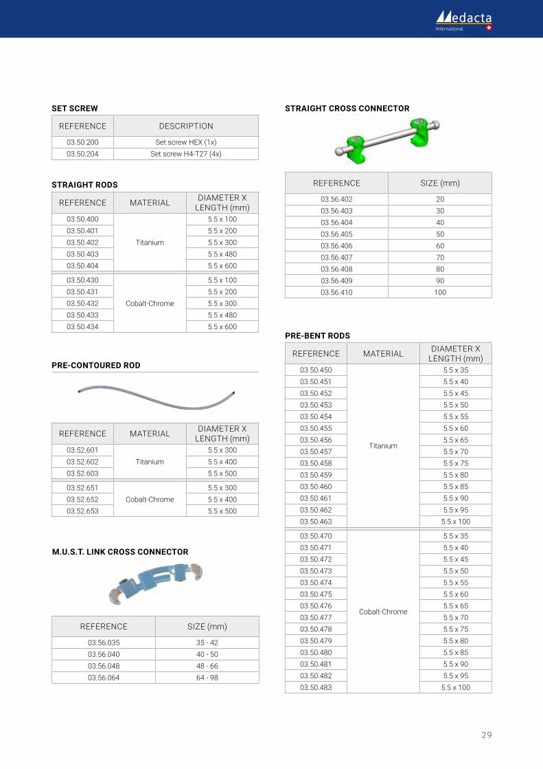
STRAIGHT RODS
REFERENCE MATERIAL DIAMETER X LENGTH (mm)
03.50.400
Titanium
5.5 x 100 03.50.401 5.5 x 200 03.50.402 5.5 x 300 03.50.403 5.5x48003.50.404 5.5 x 600
03.50.430
Cobalt-Chrome
5.5 x 100 03.50.431 5.5 x 200 03.50.432 5.5 x 300 03.50.433 5.5x48003.50.434 5.5 x 600
PRE-CONTOURED ROD
REFERENCE MATERIAL DIAMETER X LENGTH (mm)
03.52.601Titanium
5.5 x 300 03.52.602 5.5 x 400 03.52.603 5.5 x 500
03.52.651Cobalt-Chrome
5.5 x 300 03.52.652 5.5 x 400 03.52.653 5.5 x 500
SET SCREW
REFERENCE DESCRIPTION
03.50.200 Set screw HEX (1x)03.50.204 SetscrewH4-T27(4x)
M.U.S.T. LINK CROSS CONNECTOR
REFERENCE SIZE (mm)
03.56.035 35 - 4203.56.040 40 - 5003.56.048 48-6603.56.064 64-98
STRAIGHT CROSS CONNECTOR
REFERENCE SIZE (mm)
03.56.402 2003.56.403 3003.56.404 4003.56.405 5003.56.406 6003.56.407 7003.56.408 8003.56.409 9003.56.410 100
PRE-BENT RODS
REFERENCE MATERIAL DIAMETER X LENGTH (mm)
03.50.450
Titanium
5.5 x 35 03.50.451 5.5 x 40 03.50.452 5.5 x 45 03.50.453 5.5 x 50 03.50.454 5.5 x 55 03.50.455 5.5 x 60 03.50.456 5.5 x 65 03.50.457 5.5x7003.50.458 5.5x7503.50.459 5.5x8003.50.460 5.5x8503.50.461 5.5 x 90 03.50.462 5.5 x 95 03.50.463 5.5 x 100
03.50.470
Cobalt-Chrome
5.5 x 35 03.50.471 5.5 x 40 03.50.472 5.5 x 45 03.50.473 5.5 x 50 03.50.474 5.5 x 55 03.50.475 5.5 x 60 03.50.476 5.5 x 65 03.50.477 5.5x7003.50.478 5.5x7503.50.479 5.5x8003.50.480 5.5x8503.50.481 5.5 x 90 03.50.482 5.5 x 95 03.50.483 5.5 x 100
M.U.S.T.® Surgical Technique
30
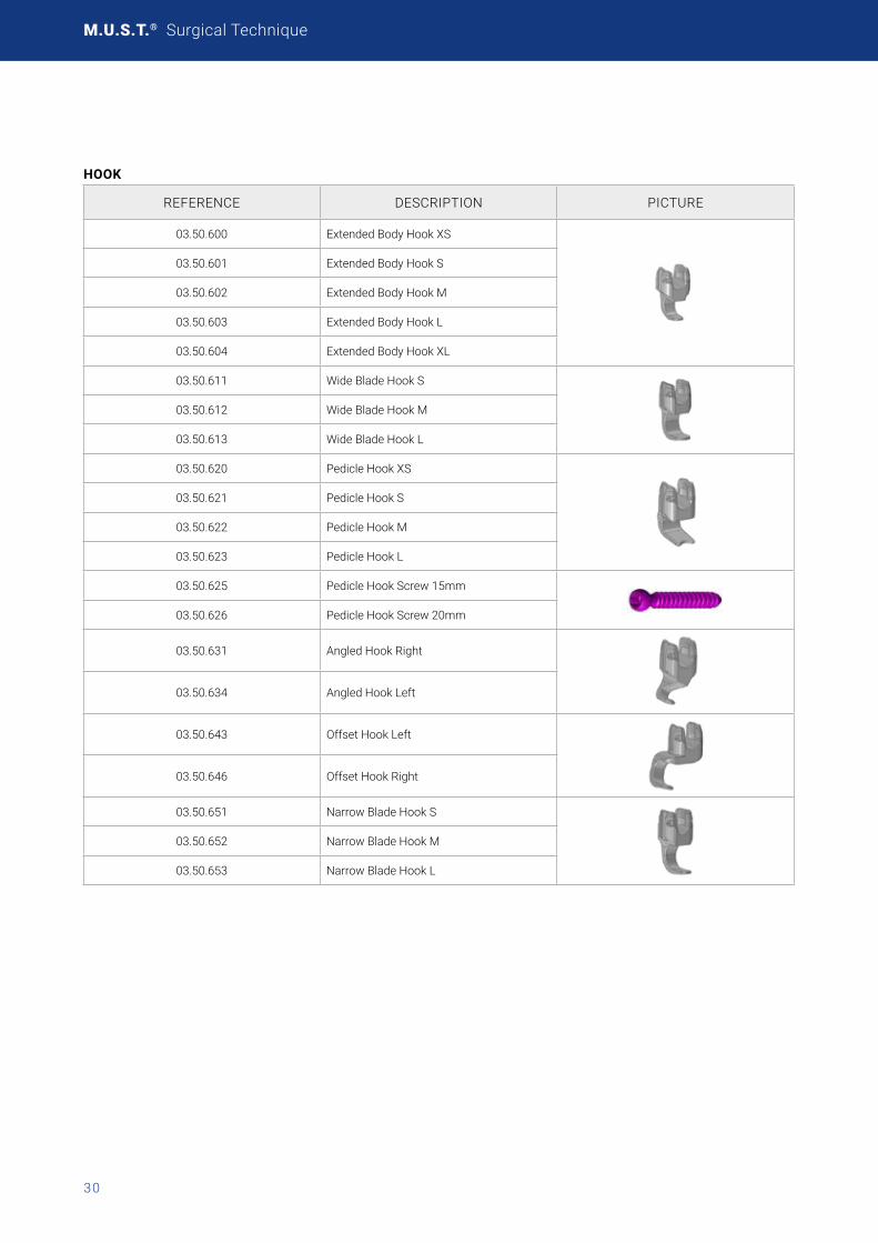
HOOK
REFERENCE DESCRIPTION PICTURE
03.50.600 Extended Body Hook XS
03.50.601 Extended Body Hook S
03.50.602 Extended Body Hook M
03.50.603 Extended Body Hook L
03.50.604 Extended Body Hook XL
03.50.611 Wide Blade Hook S
03.50.612 Wide Blade Hook M
03.50.613 Wide Blade Hook L
03.50.620 Pedicle Hook XS
03.50.621 Pedicle Hook S
03.50.622 Pedicle Hook M
03.50.623 Pedicle Hook L
03.50.625 Pedicle Hook Screw 15mm
03.50.626 Pedicle Hook Screw 20mm
03.50.631 Angled Hook Right
03.50.634 Angled Hook Left
03.50.643 Offset Hook Left
03.50.646 Offset Hook Right
03.50.651 Narrow Blade Hook S
03.50.652 Narrow Blade Hook M
03.50.653 Narrow Blade Hook L
31
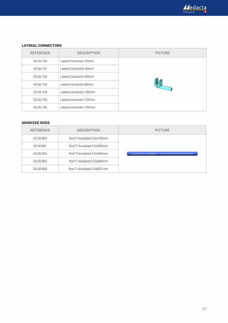
ANODIZED RODS
REFERENCE DESCRIPTION PICTURE
03.50.800 RodTiAnodized5.5x100mm
03.50.801 RodTiAnodized5.5x200mm
03.50.802 RodTiAnodized5.5x300mm
03.50.803 RodTiAnodized5.5x480mm
03.50.804 RodTiAnodized5.5x600mm
LATERAL CONNECTORS
REFERENCE DESCRIPTION PICTURE
03.56.100 Lateral Connector 20mm
03.56.101 Lateral Connector 40mm
03.56.102 Lateral Connector 60mm
03.56.103 Lateralconnector80mm
03.56.104 Lateral connector 100mm
03.56.105 Lateral connector 125mm
03.56.106 Lateral connector 150mm

M.U.S.T.® Surgical Technique
32
“DOMINO” ROD-TO-ROD CONNECTOR
REFERENCE DESCRIPTION PICTURE ROD Ø (mm)
ROD MIN DISTANCE
(INNER CLEA-RANCE) (MM)
CONNEC-TOR LEN-GHT (MM)
CONNEC-TOR MAX
WIDTH (MM)
03.56.200 In line connectorFrom5.5upto 6.35 (both sides)
n.a. 29 10.4
03.56.205 In line connector Open 5.5
5.5 (both sides) n.a. 31 14.2
03.56.206 In line connector Open 6.35
From5.5upto 6.35 (both sides)
n.a. 31 14.2
03.56.300 Domino connectorFrom5.5upto 6.35 (both sides)
1.5 16 19
03.56.301 Domino connector Wide
From5.5upto 6.35 (both sides)
5.5 16 23
03.56.302 Domino connector Vertical Screws
From5.5upto 6.35 (both sides)
1.5 16 19
03.56.303 Domino connector Vertical Screws Wide
From5.5upto 6.35 (both sides)
5.5 16 23
03.56.305 Domino connector Open 5.5
5.5 (both sides) 6 16 22.5
03.56.306 Domino connector Open 6.35
From5.5up to 6.35 (both sides)
5.2 16 22.5
03.56.307Top Loading ("tulip based") Connector Wide
5.5 (both sides) 9.4 10.5 28.5
03.56.310 Top Loading ("tulip based") Connector
5.5 (both sides) 6.4 10.5 25.5
03.56.211 M.U.S.T. Connector Setscrew (1x)
03.56.212 M.U.S.T. Connector Setscrew (2x)

33
NOTES

M.U.S.T.® Surgical Technique
34

35
Part numbers subject to change.
NOTE FOR STERILISATIONIncasetheinstrumentationisnotsterileupondelivery,itmustbecleanedbeforeuseandsterilizedinanautoclaverespectingthe regulation of the country, EU directives where applicable and following the instructions for use of the autoclave manufacturer. Fordetailedinstructionspleaserefertothedocument“RecommendationsforcleaningdecontaminationandsterilizationofMedacta International reusable orthopedic devices” available at www.medacta.com.

M.U.S.T.® Surgical Technique
ref: 99.46.12 rev. 12
Last update: August 2020
Medacta International SAStradaRegina-6874CastelSanPietro-SwitzerlandPhone+41916966060-Fax+41916966066info@medacta.ch
Findyourlocaldealerat:medacta.com/locations
AlltrademarksarepropertyoftheirrespectiveownersandareregisteredatleastinSwitzerland.This document is not intended for the US market. Please verify approval of the devices described in this document with your local Medacta representative.


![Acer One 10 [S1002] Product Brief - GfK Etilize · PDF fileMeet your crave for portability and versatility Craving for portability and versatility? Let the Acer One 10 serve you as](https://img.pdfslide.net/doc/110x75/5abcad657f8b9a76038e2b98/acer-one-10-s1002-product-brief-gfk-etilize-your-crave-for-portability-and-versatility.jpg)