Embed Size (px)
Citation preview

1TgiqmUtstlgitdatbctcaclad
st8
wfiotcapt
978 J. Opt. Soc. Am. B/Vol. 23, No. 5 /May 2006 N. Malkova and C. Z. Ning
Ultrafast directional switching in photonic-crystalbranched waveguides
using electro-optical control
N. Malkova and C. Z. Ning
Center for Nanotechnology, NASA Ames Research Center, Moffett Field, California 94035
Received August 24, 2005; revised November 4, 2005; accepted December 2, 2005; posted December 9, 2005 (Doc. ID 64328)
We propose and investigate ultrafast switching of light beams between different ports of a multibranch wave-guide in photonic crystals. The branched waveguide is made of chains of coupled defects with degenerate statesproviding guided modes. Introduced at the corner of branches is a control cell made of an electro-optical activematerial. Depending on the symmetry of the refractive index changes, light propagation can be directed tospecified direction. Dynamic changes of refractive index then provide ultrafast switching of light beams into adesired branch. © 2006 Optical Society of America
OCIS codes: 160.2100, 160.5470, 230.7370.
Fmidrtwumsw(ltrwtatomtclSsmfe
og
wc
. INTRODUCTIONhe ability of photonic crystals to control the light propa-ation at the nanoscale provides a platform for novel min-aturized photonic integrated circuits.1 One important re-uirement of the photonic integrated circuits is that theyust be able to direct the light in any desired direction.nique properties of the photonic crystals offer a few op-
ions to achieve this goal. The first method is to use theuperprism effect.2 The second method is to exploit dielec-ric properties of the photonic crystals by guiding theight through the defect states localized within the band-ap. Since a transmission through coupling between local-zed defect states does not depend on the ratio betweenhe wavelength of the light and the bend curvature of theefect chain, photonic-crystal waveguides should presum-bly allow for light guiding through any angle.3,4 Reflec-ionless light propagation through the 90 deg bend haseen presented in waveguides based on photonicrystals.4,5 In our recent paper6 we presented a design ofhe almost-reflectionless coupled-cavity waveguide with aontrol corner cell for guiding light through any acutengle. However, for certain applications in photonic cir-uits it is of primary importance to be able to switch theight propagation among several directions dynamicallynd in a controllable fashion. That is the issue that we ad-ress in this paper.There have been some efforts to design photonic-crystal
witch devices using electro-optical materials. It washeoretically predicted7 and experimentally demonstratedthat the band structure of a photonic crystal infiltratedith liquid crystal can be tuned by an external electriceld. Recently, numerical studies showed wide tunabilityf the superprism effect in two-dimensional photonic crys-als infiltrated by liquid crystal and lead lanthanum zir-onium titanate.9,10 The aim of this paper is to proposend present a method to dynamically switch the lightropagation in a photonic-crystal waveguide with mul-iple branches. Our approach is described as follows.
0740-3224/06/050978-8/$15.00 © 2
irst, we use the degenerate defect state as a guidedode. Second, a control cell at the corner of the branches
ntroduces the splitting of degenerated defect modes toetermine which branch or port light will be switched oredirected, depending on the specific symmetry of the con-rol cell. Third, the control cell consists of dielectrical rodshose refractive index can be changed significantly in altrafast fashion by applying an electrical field. As for theaterial choice for such dielectrical rods, we notice that
ignificant progress has been made in designing polymersith exceptionally high electro-optical coefficients
greater than 100 pm/V at telecommunication wave-ength) and high device quality.11 It has been reportedhat the index change in copolymers of polyvinylide fluo-ide �PVF2� can reach a few percents by switching band-idth in the gigahertz range.12 The ultimate response
ime of the electro-optical polymers discussed is associ-ted with the phase relaxation time of the �-electron sys-em. This time is typically of the order of tens to hundredsf femtoseconds.13 Such materials can be used for the rodaterials of the control cell. In contrast, the charge dis-
ribution and index of refraction in liquid crystals arehanged by molecular reorientation of ordered molecularattices under the influence of an applied electric field.uch effects can be very large. However, since the re-ponse or switching time is defined by the mass move-ent that reaches milliseconds or microseconds, such ef-
ects will be much slower than the purely ‘electronic’lectro-optics effects in the polymers.13
The change in the index of refraction of an electro-ptical material with an externally applied electric field isiven by14
�nij = −1
2nij
3�rijkEk + sijklEkEl�, �1�
here nij is the index of refraction, Ek,l are the Cartesianomponents of externally applied field, and r and s
ijk ijkl006 Optical Society of America
aopwaiow
ptteaso
2AmPsdTpdwisssEwies
utameoippscbbeg
cIcboTnp
tstt
v(po
HaFmtwtb
etbm
Te
itrTtp
Htsc
de
wda�
sp
N. Malkova and C. Z. Ning Vol. 23, No. 5 /May 2006/J. Opt. Soc. Am. B 979
re the linear (or Pockels) and quadratic (or Kerr) electro-ptical coefficients. The linear electro-optical effect isresent only in the noncentrosymmetric materials,hereas the quadratic electro-optical effect is present inll materials. The dielectric constant �ij is related to thendex of refraction through �ij=�onij
2. With the applicationf electric field, the dielectric constant of the materialould change to �̃ij=�o�nij+�nij�2.The paper is organized as follows. In Section 2 we
resent theoretical analysis of the degenerate state split-ing in square two-dimensional photonic crystal. In Sec-ion 3 we verify the theory by the numerical finite differ-nce time domain (FDTD) simulations. Finally, we designT-shaped waveguide device and give the analysis of the
tructure. Section 4 concludes the paper with a summaryf the main results.
. THEORYdefect imperfection within an ideal photonic crystal
ay create a localized resonance within the bandgap.15
hotons of certain wavelength can be locally trapped in-ide the defect volume. Depending on the symmetry, theefect mode can be either nondegenerate or degenerate.15
he degenerate state is associated with a number (de-ending on the order of degeneracy) of linearly indepen-ent wave functions. In a two-dimensional square latticeith the C4v point group symmetry, the defect rod local-
zed at the site of the lattice may support a nondegeneratetate described by the one-dimensional irreducible repre-entations, A1,2, B1,2, or the double degenerate state de-cribed by the two-dimensional irreducible representation.16 The basis of the two-dimensional representation E,hich is a 1�2 column vector with the components hav-
ng the shape of the px and py orbitals, represents theigenfunction of the double degenerate state. We willtudy the splitting of this state.
A degeneracy of a physical system is well known to benstable under certain perturbations. In solids the elec-ronic properties are fundamentally governed by thetomic character of the constituent atoms and by the sym-etry of the lattice. As a result, the degeneracy of the
lectronic state can be removed either by a perturbationn atomic level (e.g., Stark or Zeeman effect) or by break-ng the lattice symmetry through perturbation (structurehase transition). Similarly, in photonic crystals, photonicroperties are governed by dielectric contrast of the con-tituents and by symmetry of the lattice. Therefore in thisase, a perturbation potential can be a symmetry-reaking potential caused either by lattice distortion ory a perturbation in dielectric constant (e.g., owing to thelectro-optical effect). In both cases, the perturbationsenerally result in symmetry breaking of the system.
The Jahn–Teller effect in solids can be considered as alassical example of the lattice distortion perturbation.16
n this case, the splitting of a degeneracy is induced by aoupling of the degenerate electronic state with lattice vi-ration, which in turn results in a spontaneous loweringf the symmetry of the system, or in the so-called Jahn–eller phase transition. It was presented that the photo-ic analog of the Jahn–Teller effect can be observed inhotonic crystals.17 This means that the degenerate pho-
onic state, when coupled with the lattice vibrations,hould be split. Moreover, a photonic crystal subject to lat-ice vibrations can undergo the structural phase transi-ion, lowering the symmetry of the structure.
Generally speaking, the perturbed potential V is theector or scalar field function that prescribes the vectorlattice distortion) or scalar (dielectric constant change)erturbation Qr to each lattice point r. The Hamiltonianf the perturbed structure can be presented as
H = Ho + V�Qr�. �2�
ere Ho is the Hamiltonian for the ideal structure that isssociated with the degenerate state �o, Ho�i=�o
2 /c2�i.or example, for the E polarization of the electro-agnetic wave with the electric field parallel to the rods,
he wave functions �i should represent the electric field,ith the index i numerating the degenerate wave func-
ions. The unperturbed Hamiltonian in this case is giveny15
Ho =1
��r�� � �. �3�
In the perturbation theory, the solution of the Schro-dinger equation H�=�2 /c2� is expanded in the space ofhe unperturbed states �i. In the first order of the pertur-ation theory, the magnitude of the splitting will be deter-ined by the secular equation det�Vij−�2 /c2�=0, with
Vij =� �i*V�Qr��jdr. �4�
he degeneracy will survive if and only if all the matrixlements Vij are equal to zero.
Now, we want to find such a perturbation that resultsn the most efficient splitting of the degeneracy, that is,he perturbation that for the smallest change of the pa-ameters of the system will cause the biggest splitting.his implies that we want to obtain nonvanishing split-
ing with the linear term of the power expansion of theerturbed potential,
V�Qr� � �m� �V�Qr�
�Qrm �
o
Qrm. �5�
ere the index m enumerates the components of the per-urbed parameter Qr in each point of the coordinatepace. The partial derivatives of the potential V are cal-ulated at vanishing perturbed parameter, hence,��V�Qr� /�Qr
m�o is the function of only the coordinate. Un-er such conditions, the perturbation caused by the di-lectric constant change is
V���� = −���r�
�2 � � �, �6�
here ���r� is the coordinate-dependent magnitude of theielectric constant change. In general, since all Qr ����re arbitrary, the matrix elements Vij=0 if�i
*�V�Qr� /�Qr�jdr=0.Next we want to take advantage of the symmetry of the
tructure and classify all perturbations by symmetry. Anyossible perturbation of the square lattice can be repre-

sbssddop
pbtftetsTeossfVfVd
tttaprHE�
satT1mgttad�dp
wnsTtfmtccoacti=tttmssvnittsos
3Wgtg
F(Tcdtcrs
980 J. Opt. Soc. Am. B/Vol. 23, No. 5 /May 2006 N. Malkova and C. Z. Ning
ented as a linear combination of the elementary pertur-ations transforming according to the irreducible repre-entations of the C4v group, which consist of a fullyymmetrical representation A1, nonsymmetrical one-imensional representations A2, and B1,2, and a two-imensional representation E. The symmetry propertiesf the elementary (irreducible) perturbations can be thenrecisely specified by the character table.16
The group theory provides a prescription of finding theerturbation with nonvanishing matrix elements Vij. It isased on the idea that the integral Vij [Eq. (4)] is not iden-ically equal to zero only if the integrant �i
*V�Qr��j trans-orms according to the identity representation. That is,he square of the irreducible representation of the degen-rate state must contain the irreducible representation ofhe perturbed potential.16 For the E degenerate defecttate studied, we can easily find that E2=A1+A2+B1+B2.herefore nontrivial perturbations that can lift the degen-racy of the E defect state should be described by the A2r B1,2 irreducible representations. We disregard the fullymmetrical perturbation A1 that results in an identicalhift of the degenerate state. For the perturbation trans-orming according to the A2 irreducible representation,
xxA2=Vyy
A2=0 and VxyA2=−Vyx
A2. The last relation implies thator the real wave functions that are px and py orbitals,
xyA2=Vyx
A2=0. Hence, the A2 perturbation cannot split theegeneracy of the E defect state. For the perturbation
Table 1. Character Table for the B1 and B2Representations
E C2 2C4 2�v 2�v�
B1 1 1 −1 1 −1B2 1 1 −1 −1 1
ig. 1. Perturbed potentials that transform through the [(a) andc)] B1 and [(b) and (d)] B2 irreducible representations. (a) and (b)he perturbation caused by the lattice distortions. The filledircle shows the defect rod, and the arrows indicate the latticeisplacements. (c) and (d) The perturbation caused by change inhe dielectric constant. The plus and minus signs denote an in-rease or decrease in the dielectric constant of the perturbedods, �̃r
±=�r±��. The symmetry operations of the C4v group arehown in (a).
ransforming according to the B1 irreducible representa-ion, Vxx
B1=−VyyB1=VB1 and Vxy
B1=VyxB1=0. Such a perturba-
ion will give rise to two split levels, �1,2B1 =�o±VB1, char-
cterized by the �px and �py eigenvectors. For theerturbation transforming according to the B2 irreducibleepresentation, we have Vxx
B2=VyyB2=0 and Vxy
B2=VyxB2=VB2.
ence the B2 perturbed potential will split the degeneratephoton state into the two levels, �1.2
B2 =�o±VB2, with thepx±py eigenvectors.
Using now the character table for the C4v group, we canpecify the potentials that transform according to the B1nd B2 irreducible representations.16 The characters ofhe B1 and B2 irreducible representations are shown inable 1. Here E (identity operation), C2 (rotation over80°), C4 (rotation over 90°), and �v, �v� (reflections in twoirror planes) are the symmetry operations of the C4v
roup, shown in Fig. 1(a). Since �E�=�C2�=��v�=1, po-ential VB1 does not change under the E identity opera-ion, the rotation C2, and one mirror-plane reflection �v,ccording to the B1 irreducible representation. While un-er the rotation C4 and another mirror plane reflectionv�, the potential VB1 changes the sign. The VB2 potentialiffers from the VB1 only by the reflection in two mirrorlanes.This analysis is summarized in Fig. 1. For simplicity,
e present only the potentials that disturb the nearesteighbors to the defect. Generally, the perturbation canpread to the next neighbors. We distinguish two cases.he first is when the perturbation is induced by the lat-
ice distortion. The relevant perturbed potentials, trans-orming through the B1 and B2 representations, are sche-atically shown in Figs. 1(a) and 1(b), respectively. Here
he arrows indicate the lattice displacements. The secondase is when the perturbation is caused by the spatialhange in the dielectric constant of the structure. Profilesf the dielectric constant for the potentials transformingccording to the B1 and B2 representations, are schemati-ally illustrated in Figs. 1(c) and 1(d), respectively. Herehe plus and minus signs denote an increasing or decreas-ng of the dielectric constant of the perturbed rods �̃r
±
�r±��, where �r is the dielectric constant of the unper-urbed rods. From the symmetry of the perturbed poten-ial in dielectric system [Figs. 1(c) and 1(d)] we can seehat in order to design such a potential we should have aechanism for increasing or decreasing the dielectric con-
tant of the nearest neighbors to the defect in the pre-cribed way. As shown in Eq. (1), such a tool can be pro-ided by the linear electro-optical effect inoncentrosymmetrical materials.11,12 By electric field pol-
ng, such a material can be polarized in opposite direc-ions by the poling field.11 Then the driving field is alonghe poling direction in one rod (or one of the two closelypaced halves) and against the poling direction in thether rod (or in the other of the halves), resulting in a de-ired symmetry of the perturbed potential.
. NUMERICAL RESULTSe proceed with the numerical simulations to verify the
roup theory analysis presented above. Using the FDTDechnique,18 we calculated the splitting of the double de-enerate defect state when we gradually increased mag-

ncwartqrpne
vatssitwdc
Fvt hown.
N. Malkova and C. Z. Ning Vol. 23, No. 5 /May 2006/J. Opt. Soc. Am. B 981
itude of the perturbation. We consider a square photonicrystal with lattice constant a composed of dielectric rodsith the dielectric constant �r=11.9 that are embedded innother medium with �=1. We assume that radius of theods is r=0.2a. Such a structure has the first bandgap forhe E polarization of the electromagnetic wave in the fre-uency range �̃=�a /2�c= 0.28,0.48�.17 Increasing theadius of a single rod to rd=0.3a creates a defect that sup-orts the double-degenerate E photon mode. The reso-ance frequency of this defect is �̃o=0.358, that is, almostxactly in the middle of the first bandgap.
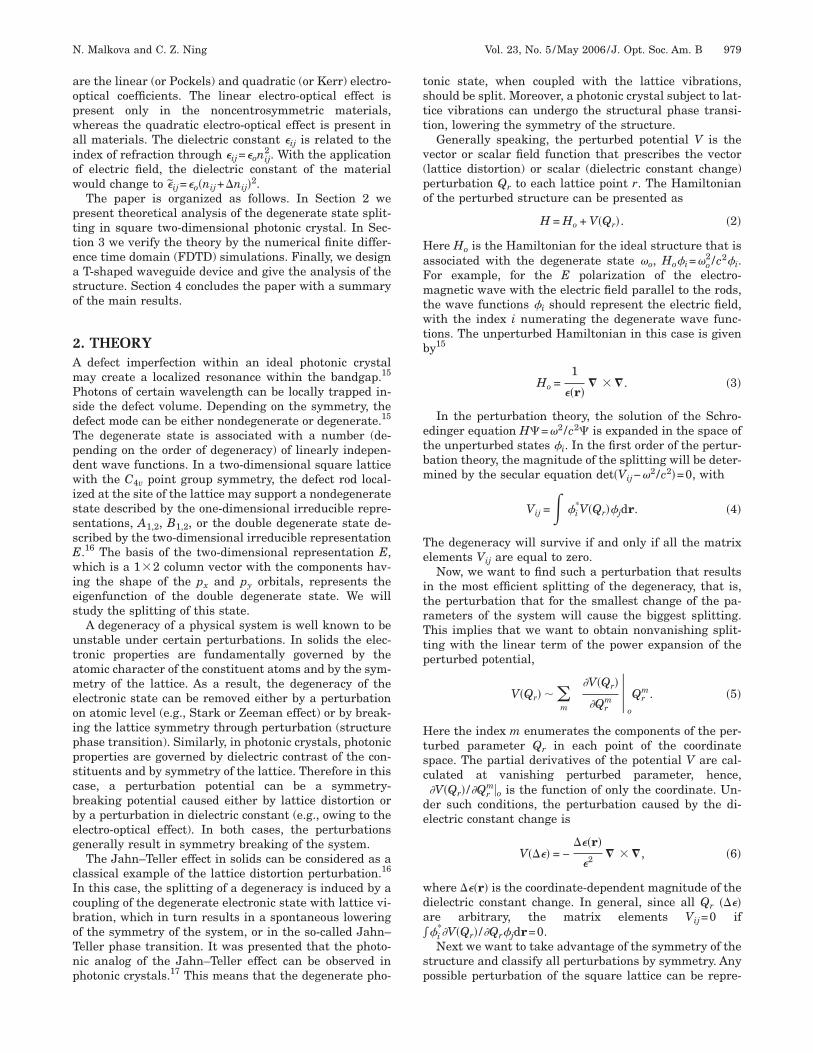
ig. 2. (Color online) Frequency splitting of the defect level indersus (a) the dielectric constant change and (b) the lattice distorhe [(c) and (d)] B1 mode and with the [(e) and (f)] B2 mode are s
The results of the degenerate E photon state splittingersus the magnitude of the dielectric constant changere presented in Fig. 2(a). We compare these data withhe splitting induced by the lattice distortion, which arehown in Fig. 2(b). The eigenfunctions of the two splittates caused by perturbation of the B1 and B2 modes arellustrated in Figs. 2(c) and 2(d) and 2(e) and 2(f), respec-ively. First, from comparison of Fig. 2(a) with Fig. 2(b),e conclude that similar to the perturbation of the latticeistortion the splitting caused by dielectric constanthange shows a linear scaling behavior as a function of
y the B1 mode (solid curve) and by the B2 mode (dashed curve)he eigenfunctions for the split states caused by interaction with
uced btion. T

tcmpmstittssmiw
neTcttpd
wttcs
ffHppbtte
ttwsro2Tttvtlt=w1r
ss2topc
atcirbosttnocdposftFrF=afmc
nt
Fatb
982 J. Opt. Soc. Am. B/Vol. 23, No. 5 /May 2006 N. Malkova and C. Z. Ning
he perturbed parameter (the magnitude of the dielectriconstant change). This verifies that the splitting is causedostly by the linear term of the power expansion of the
erturbed potential shown in Eq (5). Second, in agree-ent with the theoretical prediction, the degenerate state
plits into the �px and �py states in the case of the per-urbation through the B1 mode [Figs. 2(c) and 2(d)] andnto the �px±py states in the case of the perturbationhrough the B2 mode [Figs. 2(e) and 2(f)]. Third, the split-ing caused by the B1 mode is more than twice as big thanplitting by the B2 mode. The reason for this is that theplitting by the B1 mode is associated with the diagonalatrix element Vxx
B1, whereas the splitting by the B2 modes associated with the off-diagonal matrix element Vxy
B2,hich is presumably less effective than the diagonal one.However, in spite of similarities in symmetry, we also
ote an important difference between perturbing the di-lectric constant and perturbing the lattice distortion.he frequency splitting induced by the dielectric constanthange is much less than that induced by the lattice dis-ortion for the same relative change. The explanation forhis fact follows from a comparison of the two perturbedotentials V���� given by Eq. (6) and V��R�, the latticeistortion perturbed potential given by
V��R� = −�R�r�
�2
��
�r� � �, �7�
here �R�r� is the coordinate-dependent lattice distor-ion. We see that for the periodical dielectric structure,he factor �� /�r in Eq (7) can be considerably large in thease of the lattice distortion, leading to a large frequencyplitting.
In this study so far, we included the perturbation onlyor the nearest neighbors, as shown in Fig. 1, since the de-ect interacts most strongly with the nearest neighbors.owever, the splitting effect can be larger if the perturbedotential spreads out to the next neighbors. It is also im-ortant to note that in the photonic crystals we can com-ine both lattice distorsion and index change. By choosinghe sign and value of the perturbations of the lattice dis-ortion and dielectric constant change, we can increase orxactly cancel the splitting effect.
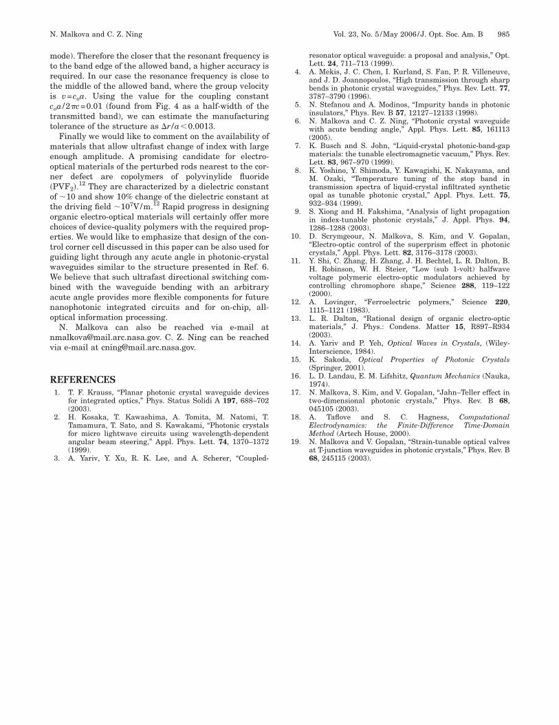
We now present application of the effect in ultrafast op-ical switching. Using the two-dimensional photonic crys-al considered above, we design a T-shaped coupled-cavityaveguide, which is shown in Fig. 3. This waveguide con-
ists of three branches. The first branch is along the x di-ection from the source (S) to the bending corner. The sec-nd branch is along the y direction from the corner to port(P2). The third branch is from the corner to port 1 (P1).
o analyze this structure, we use the FDTD technique18
o solve the wave-propagation problem. Our computa-ional domain is shown in Fig. 3. Each unit cell was di-ided into 20�20 discretization grid cells. The computa-ional domain was surrounded by perfectly matchedayers, with the thickness corresponding to 10 layers ofhe discretization grid. Each time step was equal to �t1/ �2�xc�. The numerical simulations were performedith the total number of the time steps equal to 100 000,50 000 and 200 000 in order to check if the stationaryegime is reached. A symmetrical Gaussian beam with re-
pect to the x axis was launched from the input of thetructure (S in Fig. 3). The width of the beam was equal to0 grid cells. A frequency spectrum of the source coveredhe region of interest ��̃=0−0.4. To find the transmissionf the structure, we collected the signal at the two outputorts and compared this data with the reference signalollected at the input of the structure.
The computed transmission coefficients of the structuret ports 1 and 2 are shown in Figs. 4(a) and 4(b), respec-ively. We note that without additional perturbations theoupling of the excited wave into the 90 deg bend branchs very weak. The transmission coefficient at port 2eaches 20% only. The poor transmission can be explainedy the frequency mismatch between the resonance peaksf the first and second branches shown in Fig. 4(c) by theolid and dashed curves, respectively. The coupling be-ween the first and second branches could be improved ifhe corner defect overlaps in frequency with the reso-ance peaks in both branches. On the other hand, the lay-ut of the corner defects tells us that the best couplingould be achieved through the �px+py state of the cornerefect. Hence, we have to distort the corner cell by the B2erturbed potential, as schematically shown in the insetf Fig. 3. When we gradually increase the dielectric con-tant change of the corner cell �� /�r to 0.2, the corner de-ect splits into the �px+py and �px−py states shown byhe dash-dotted and dotted vertical lines, respectively, inig. 4. As a result, the transmission coefficient at port 2eaches as much as 80% [dash-dotted and solid lines inig. 4(b)]. For the dielectric constant change of �� /�r0.2 [solid curve in Fig. 4(b)], the transmission coefficientt the resonant frequency at port 2 increases by almostour times. Simultaneously at this frequency, the trans-ission coefficient at port 1 drops off significantly [solid
urve in Fig. 4(a)].Theoretical explanation of the effect is based on reso-
ant tunneling between the two waveguide branches.19 Inhis structure, the corner defect states work as a gate con-
ig. 3. Studied T-shaped coupled-cavity waveguide. Source (S)nd two ports (P1, P2) are shown. The insert presents the per-urbation of the dielectric constant for the corner cell. The filledlack circles show the defect rod.

nstbtmmb
qt�sibtns[
wattps
Fwft
Fncv1
Fs(fiwdtsvtqp
N. Malkova and C. Z. Ning Vol. 23, No. 5 /May 2006/J. Opt. Soc. Am. B 983
ecting the waveguide branches. As soon as the properplit-defect state matches in frequency with the transmit-ed bands of the waveguide branches before and after theending, the resonant condition is satisfied. Hence, theransmission coefficient at port 2 shows a sharp maxi-um at this frequency, whereas that of at port 2 shows ainimum. This is visualized in Figs. 4(a)–4(c). The distri-
ution of the z component of the electric field in the fre-
ig. 4. (Color online) Computed transmission coefficient of thetructure for �� /�r=0 (dashed curve), 0.1 (dash-dotted curve), 0.2solid curve), at (a) port 1 and (b) port 2. The transmission coef-cients of the first (solid curve) and second branch (dashed line)ithout coupling are shown in (c). The frequency of the double-egenerate defect state of the undistorted corner cell is shown byhe solid vertical line. Frequencies of the �px+py and �px−pytates at �� /�r=0.20 are shown by the dash-dotted and dottedertical lines, respectively. The distribution of the z component ofhe electric field in the frequency domain for the resonant fre-uency corresponding to the maximum of the transmission atorts 1 and 2 at (d) �� /�r=0 and (e) 0.20 are shown.
uency domain at the resonant frequency correspondingo the maximum of the transmission at ports 1 and 2 at� /�r=0 and 0.2 is presented in Figs. 4(d) and 4(e), re-pectively. It is important to note that transmitted powern the branched coupled-cavity waveguide is determinedy the spectral overlap between the resonance peaks ofhe branches. For the structure studied with a limitedumber of the defects on each branch, the efficiency ofwitching is restricted by the width of the resonant peakssee Fig. 4(c)].
We conclude this section by showing that the T-shapedaveguide considered represents a dynamically switch-ble optical valve. Calculated switching characteristics ofhe waveguide are presented in Fig. 5. The maximumransmission in the frequency range �̃= 0.353,0.356� atorts 1 and 2 is shown by the dashed and solid curves, re-pectively. The switch cycle is illustrated in Fig. 6. For the
ig. 5. Calculated switching characteristics of the T-shapedaveguide shown in Fig. 3. The maximum transmission in the
requency range �̃= 0.353,0.356� at ports 1 and 2 is shown byhe dashed and solid curves, respectively.
ig. 6. Switch cycle at the frequency �̃=0.355. (a) The exter-ally applied electric field to the corner cell drives the indexhange of the rods nearest to the corner defect to the requiredalue. This results in dynamic switching of the light from (b) portto (c) port 2.

drpopcqltarnmbbtf2
4IsutpepIdcpapdntitpfitrtstrrhtr
1=Fi==vnLs
hTbtfwotTh32t3wcidtsbo1pi
ttvakopb�=td
mucifdkoedtt(d
t�ds�o�
984 J. Opt. Soc. Am. B/Vol. 23, No. 5 /May 2006 N. Malkova and C. Z. Ning
evice implementation, the corner defect should be sur-ounded by the rods made of the linear electro-opticalolymers mentioned at the begining of the paper, or anyther materials of similar nature. Then the externally ap-lied electric field to the corner cell drives the indexhange of the rods nearest to the corner defect to the re-uired value. This results in dynamical switching of theight from the source into desired directions of propaga-ion at gigahertz speed. A real switching process is char-cterized by a delay in transmission determined by theatio of the length of the waveguide branch, from the cor-er element to the port to the group velocity of the pxodes (on the first branch) or the py modes (on the second
ranch). By symmetry, the group velocities of the tworanches are similar, estimated to be vg�0.1c, where c ishe light velocity. Then for a structure with 10 defect rodsrom the corner to the port, the delay in transmission is0a /vg�10−13s.
. SUMMARYn conclusion, we have studied the possibility of ultrafastwitching in multibranch photonic-crystal waveguides bysing the degeneracy splitting of the defect states in pho-onic crystals. Using the group theory we identified theerturbed potentials that split the degeneracy in the mostfficient way, that is, the potential that for the smallesterturbation in the system results in the biggest splitting.n the artificial photonic crystals, the perturbation can beesigned either as a lattice distortion or as a dielectriconstant change. We focused on the second type of theerturbation in this paper. Through detailed group-theorynalysis it was shown that the desired symmetry of theerturbed potential can be achieved by the refractive in-ex changes provided by the linear electro-optical effect inoncentrosymmetrical materials.11,12 In terms of makinghe switching cell, we suggest that all four rods surround-ng the corner defect should be made of electro-optical ma-erial. Using push–pull poling,11 such a material can beolarized in opposite directions by the poling electriceld.11 Then the driving field applied to the top and bot-om of the structure is along the poling direction in oneod (or in one half of a rod) and against the poling direc-ion in the other rod (or in other half), resulting in a de-ired symmetry of the perturbed potential. To get the po-ential transforming through the B2 irreducibleepresentation, it is not necessary to pole two halves of aod separately. Another possibility is that one can use twoalves that are put into close proximity so that for the op-ical purpose they act just like one rod but are two sepa-ate pieces for electrical poling.
For the devices operating on the wavelength of.55 m, the lattice constant of the crystal is given by a1.55�o, where �o is the normalized resonant frequency.or the structure studied, this gives a=5.5 m. Accord-
ngly, the radius of the rods should be equal to 0.2a1.1 m and the radius of the defect rods is 0.3a1.65 m. The length of the rods L is determined by thealidity of the two-dimensional approximation for photo-ic crystal. It requires that the aspect ratio of the rods,/r, must be much larger than 1, e.g., 10. Such rods
hould be within the capability of the current technology.
For practical applications, it is important to have aigh-enough extinction ratio defined as 10 log10 Pon/Poff.he structure used shows the switching of transmissionetween 20% �Poff� and 80% �Pon�, corresponding to an ex-inction ratio of 6 dB. It is interesting to know if there is aundamental reason for incomplete switching. In otherords, can a complete switching (with an extinction ratiof infinity) be achieved for relatively small index changehat is within the reach of the current experiment? The-shaped waveguide studied here can be considered as aeterojunction between two defect chains (branches 1 and) that are connected through the 90 degree bent (branch). Complete switching can be achieved if the split state ofhe corner defect is outside of the allowed band of branchbut within the allowed band of branches 1 and 2. Theidth of the allowed band is directly determined by the
oupling between the two nearest-neighbor defects, whichs roughly proportional to the inverse of the square of theistance between the defects.6 For example, in the struc-ure with defects separated by twice the distance in thetructure studied, the width of the allowed band shoulde 4 times narrower. Then the split defect state will moveut of the allowed band at an index change of less than0%. Therefore we believe that at least theoretically, theerformance of the device can be much better even for thendex change of 20% or less.
In this paper we considered the two-dimensional pho-onic crystals. The confinement in the out-of-plane direc-ion is an important concern for any photonic-crystal de-ice. However, unavoidable out-of-plane losses identicallyffect light propagation in any direction in the plane, thuseeping the ratio of the transmitted powers at both portsf the structure unchanged. If we define the contrast ofower transmission as the ratio of the transmitted powersetween two ports as P1/P2, this ratio will be increased by20 times after perturbation of the corner cell at �� /�r0.2, irrespective of loss from the third dimension. Thus
he main results of the paper will still be valid for a three-imensional structure.It is important to note that the dispersion of the trans-itted band will put a limit on how short of a pulse can besed for such switching. The dispersion relation of theoupled cavity waveguide is given by �=�o+co cos�ka� (cos the coupling constant between the nearest-neighbor de-ects sitting on the branch, and k is momentum). The me-ium is considered to be dispersive, and pulse cannoteep the shape if the second-order terms in the expansionver k cannot be neglected. The dispersion is equal to zeroxactly at the middle of the transmitted band, whereasispersion goes to infinity at the band edge. In our casehe resonance peak of the transmission at port 2 lies closeo the middle of the transmitted bands for both branchessee Fig. 4); therefore the pulse satisfying the above con-ition can propagate without broadening.An important issue of the photonic-crystal devices is
he tolerance to fabrication imperfection of the structure,r. This problem becomes of particular importance for theevices with narrow bandwidth, ��. For the studiedtructure, ��a /2�c�0.0025 with the resonance frequencya /2�c�0.355 (see Fig. 4). The manufacturing tolerancef the structure is determined by the value �r�2�v /�2��� (where v is the group velocity of the guided
mtrtictt
meon�otocetgwWbano
nv
R
1
1
1
1
1
1
1
1
1
1
N. Malkova and C. Z. Ning Vol. 23, No. 5 /May 2006/J. Opt. Soc. Am. B 985
ode). Therefore the closer that the resonant frequency iso the band edge of the allowed band, a higher accuracy isequired. In our case the resonance frequency is close tohe middle of the allowed band, where the group velocitys v=coa. Using the value for the coupling constantoa /2�c=0.01 (found from Fig. 4 as a half-width of theransmitted band), we can estimate the manufacturingolerance of the structure as �r /a�0.0013.
Finally we would like to comment on the availability ofaterials that allow ultrafast change of index with large
nough amplitude. A promising candidate for electro-ptical materials of the perturbed rods nearest to the cor-er defect are copolymers of polyvinylide fluoridePVF2�.12 They are characterized by a dielectric constantf �10 and show 10% change of the dielectric constant athe driving field �107V/m.12 Rapid progress in designingrganic electro-optical materials will certainly offer morehoices of device-quality polymers with the required prop-rties. We would like to emphasize that design of the con-rol corner cell discussed in this paper can be also used foruiding light through any acute angle in photonic-crystalaveguides similar to the structure presented in Ref. 6.e believe that such ultrafast directional switching com-
ined with the waveguide bending with an arbitrarycute angle provides more flexible components for futureanophotonic integrated circuits and for on-chip, all-ptical information processing.
N. Malkova can also be reached via e-mail [email protected]. C. Z. Ning can be reachedia e-mail at [email protected].
EFERENCES1. T. F. Krauss, “Planar photonic crystal waveguide devices
for integrated optics,” Phys. Status Solidi A 197, 688–702(2003).
2. H. Kosaka, T. Kawashima, A. Tomita, M. Natomi, T.Tamamura, T. Sato, and S. Kawakami, “Photonic crystalsfor micro lightwave circuits using wavelength-dependentangular beam steering,” Appl. Phys. Lett. 74, 1370–1372(1999).
3. A. Yariv, Y. Xu, R. K. Lee, and A. Scherer, “Coupled-
resonator optical waveguide: a proposal and analysis,” Opt.Lett. 24, 711–713 (1999).
4. A. Mekis, J. C. Chen, I. Kurland, S. Fan, P. R. Villeneuve,and J. D. Joannopoulos, “High transmission through sharpbends in photonic crystal waveguides,” Phys. Rev. Lett. 77,3787–3790 (1996).
5. N. Stefanou and A. Modinos, “Impurity bands in photonicinsulators,” Phys. Rev. B 57, 12127–12133 (1998).
6. N. Malkova and C. Z. Ning, “Photonic crystal waveguidewith acute bending angle,” Appl. Phys. Lett. 85, 161113(2005).
7. K. Busch and S. John, “Liquid-crystal photonic-band-gapmaterials: the tunable electromagnetic vacuum,” Phys. Rev.Lett. 83, 967–970 (1999).
8. K. Yoshino, Y. Shimoda, Y. Kawagishi, K. Nakayama, andM. Ozaki, “Temperature tuning of the stop band intransmission spectra of liquid-crystal infiltrated syntheticopal as tunable photonic crystal,” Appl. Phys. Lett. 75,932–934 (1999).
9. S. Xiong and H. Fakshima, “Analysis of light propagationin index-tunable photonic crystals,” J. Appl. Phys. 94,1286–1288 (2003).
0. D. Scrymgeour, N. Malkova, S. Kim, and V. Gopalan,“Electro-optic control of the superprism effect in photoniccrystals,” Appl. Phys. Lett. 82, 3176–3178 (2003).
1. Y. Shi, C. Zhang, H. Zhang, J. H. Bechtel, L. R. Dalton, B.H. Robinson, W. H. Steier, “Low (sub 1-volt) halfwavevoltage polymeric electro-optic modulators achieved bycontrolling chromophore shape,” Science 288, 119–122(2000).
2. A. Lovinger, “Ferroelectric polymers,” Science 220,1115–1121 (1983).
3. L. R. Dalton, “Rational design of organic electro-opticmaterials,” J. Phys.: Condens. Matter 15, R897–R934(2003).
4. A. Yariv and P. Yeh, Optical Waves in Crystals, (Wiley-Interscience, 1984).
5. K. Sakoda, Optical Properties of Photonic Crystals(Springer, 2001).
6. L. D. Landau, E. M. Lifshitz, Quantum Mechanics (Nauka,1974).
7. N. Malkova, S. Kim, and V. Gopalan, “Jahn–Teller effect intwo-dimensional photonic crystals,” Phys. Rev. B 68,045105 (2003).
8. A. Taflove and S. C. Hagness, ComputationalElectrodynamics: the Finite-Difference Time-DomainMethod (Artech House, 2000).
9. N. Malkova and V. Gopalan, “Strain-tunable optical valvesat T-junction waveguides in photonic crystals,” Phys. Rev. B
68, 245115 (2003).