Embed Size (px)
Citation preview

UFLEX15
UFLEX15
A WORLD OFMARINE
EQUIPMENT
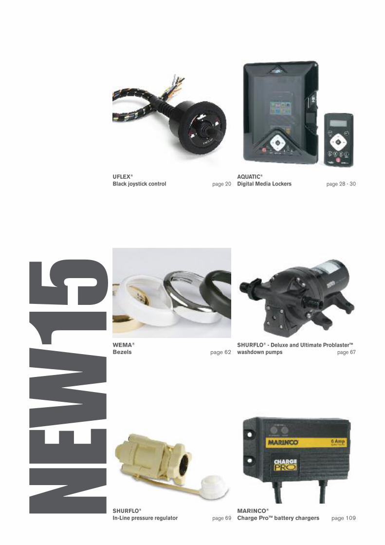
WEMA®
Bezels page 62
SHURFLO®
In-Line pressure regulator page 69
SHURFLO® - Deluxe and Ultimate Problaster™washdown pumps page 67
MARINCO®
Charge Pro™ battery chargers page 109
UFLEX®
Black joystick control page 20AQUATIC®
Digital Media Lockers page 28 - 30
NEW
15
1
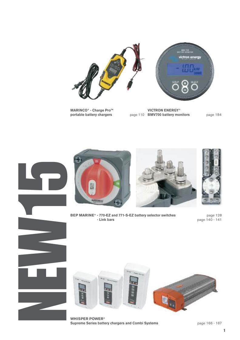
BEP MARINE® - 770-EZ and 771-S-EZ battery selector switches page 128- Link bars page 140 - 141
WHISPER POWER®
Supreme Series battery chargers and Combi Systems page 166 - 167
MARINCO® - Charge Pro™ portable battery chargers page 110
NEW
15VICTRON ENERGY®
BMV700 battery monitors page 184
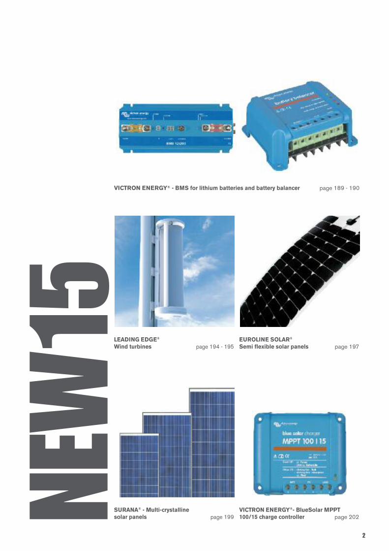
VICTRON ENERGY® - BMS for lithium batteries and battery balancer page 189 - 190
LEADING EDGE®
Wind turbines page 194 - 195EUROLINE SOLAR®
Semi flexible solar panels page 197
SURANA® - Multi-crystalline solar panels page 199
VICTRON ENERGY®- BlueSolar MPPT100/15 charge controller page 202
2
NEW
15
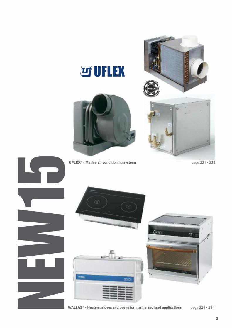
UFLEX® - Marine air conditioning systems page 221 - 228
3
WALLAS® - Heaters, stoves and ovens for marine and land applications page 229 - 234NEW
15
®®
4
INDEX
Uflex S.r.l. declines any liability for possiblemistakes in this catalogue due to printingerrors.The descriptions and guidelines shown in thiscatalog should be used as general referenceonly. For any further information pleasecontact our Technical Service.
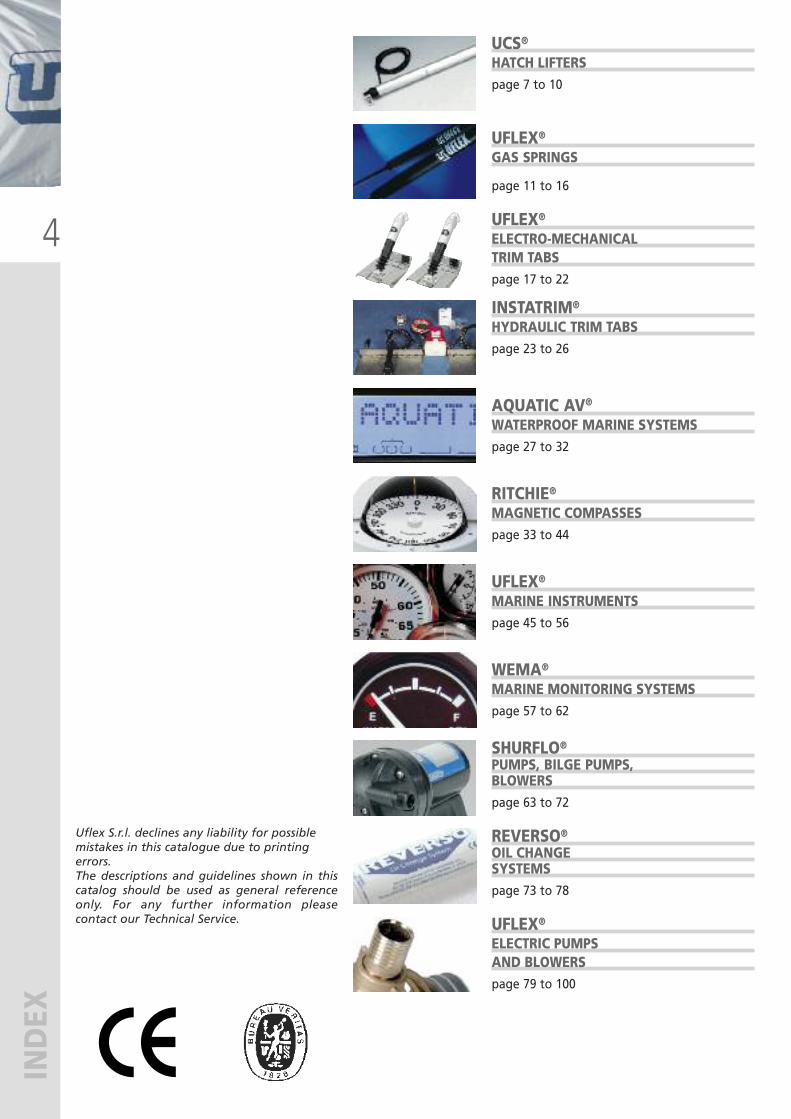
UCS®HATCH LIFTERSpage 7 to 10
UFLEX®
GAS SPRINGS
page 11 to 16
UFLEX®
ELECTRO-MECHANICALTRIM TABSpage 17 to 22
INSTATRIM®
HYDRAULIC TRIM TABSpage 23 to 26
AQUATIC AV®
WATERPROOF MARINE SYSTEMSpage 27 to 32
RITCHIE®MAGNETIC COMPASSESpage 33 to 44
UFLEX®
MARINE INSTRUMENTSpage 45 to 56
WEMA®
MARINE MONITORING SYSTEMSpage 57 to 62
SHURFLO®
PUMPS, BILGE PUMPS,BLOWERSpage 63 to 72
REVERSO®
OIL CHANGESYSTEMSpage 73 to 78
UFLEX®
ELECTRIC PUMPSAND BLOWERSpage 79 to 100
5
INDEX
Uflex S.r.l. declines any liability for possiblemistakes in this catalogue due to printingerrors.The descriptions and guidelines shown in thiscatalog should be used as general referenceonly. For any further information pleasecontact our Technical Service.
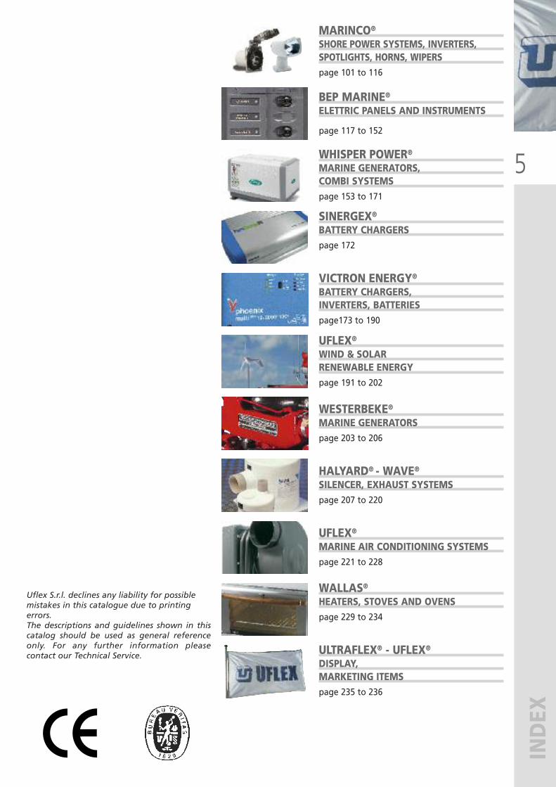
MARINCO®
SHORE POWER SYSTEMS, INVERTERS,SPOTLIGHTS, HORNS, WIPERSpage 101 to 116
BEP MARINE®ELETTRIC PANELS AND INSTRUMENTS
page 117 to 152
WHISPER POWER®MARINE GENERATORS,COMBI SYSTEMSpage 153 to 171
SINERGEX®
BATTERY CHARGERSpage 172
VICTRON ENERGY®
BATTERY CHARGERS,INVERTERS, BATTERIESpage173 to 190
UFLEX®
WIND & SOLARRENEWABLE ENERGYpage 191 to 202
WESTERBEKE®MARINE GENERATORSpage 203 to 206
HALYARD® - WAVE®SILENCER, EXHAUST SYSTEMSpage 207 to 220
UFLEX®
MARINE AIR CONDITIONING SYSTEMSpage 221 to 228
WALLAS®HEATERS, STOVES AND OVENSpage 229 to 234
ULTRAFLEX® - UFLEX®
DISPLAY,MARKETING ITEMSpage 235 to 236

UFLEX
ULTRAFLEX
UFLEX - Renewable Energy
ULTRAFLEX CONTROL SYSTEMS
INDUSTRIA di LEIVI
UFLEX USA
®
Systems and accessories for alternative energy applications
Window and skylight remote controls.Innovative LED road signs
Mechanical remote controls in the industrial field
Manufacturing the world’s finest marine products
Worldwide distribution of marine accessories
Steering and control systems for pleasure boats
1935 - 2015Ultraflex Group has 80 years of
experience in manufacturing
and distributing the highest
quality and most innovative
products.
The Ultraflex Group affiliate
Companies that design and
produce widely known
equipments in the marine,
industrial, architectural,
Led technology and alternative
energy fields.
Quality Management SystemThe Ultraflex and Uflex Quality Management Systems are
certified CISQ-IQNet by the Italian Shipping Registry (RINA), in
conformity with the UNI EN ISO 9001 rule, certification n°
6669/02/S (former 420/96). Certification Uflex n° 8875/03/S.
The quality management system involves all the company
resources and processes starting from the design, in order to:
• Assure product quality to the customer
• Set up the actions to maintain and improve the quality
standards constantly
• Pursue a continuous process improvement to meet the market
needs
• Maintain and verify conformity with ABYC requirements.
The Ultraflex Environmental Management System is certified
CISQ-IQNet by the Italian Shipping Registry (RINA), in
conformity with the UNI EN ISO 14001. Ultraflex certification
n° EMS-1282/S.
Constantly test the products to verify their conformity with the
EEC 94/25 and ABYC (American Boat and Yacht Council)
requirements.
1935-2015
ULTRAFLEX CONTROL SYSTEMS S.r.l.
®
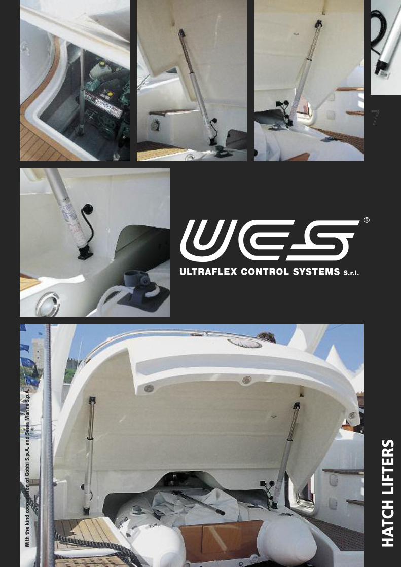
7
HATCH LIFTERS
With the kind cooperation of Gobbi S.p.A. and Sessa Marine S.p.A.
8
HATCH LIFTERS
A
Ø
42(1.65”)
27.5(1.06”)
27.5(1.06”)
Ø 6.5
Ø 4
8 1.
9”
MODEL PART No. VOLTS STROKE LENGTH A(FULL CLOSED ACTUATOR)
EXTERNAL DIA.
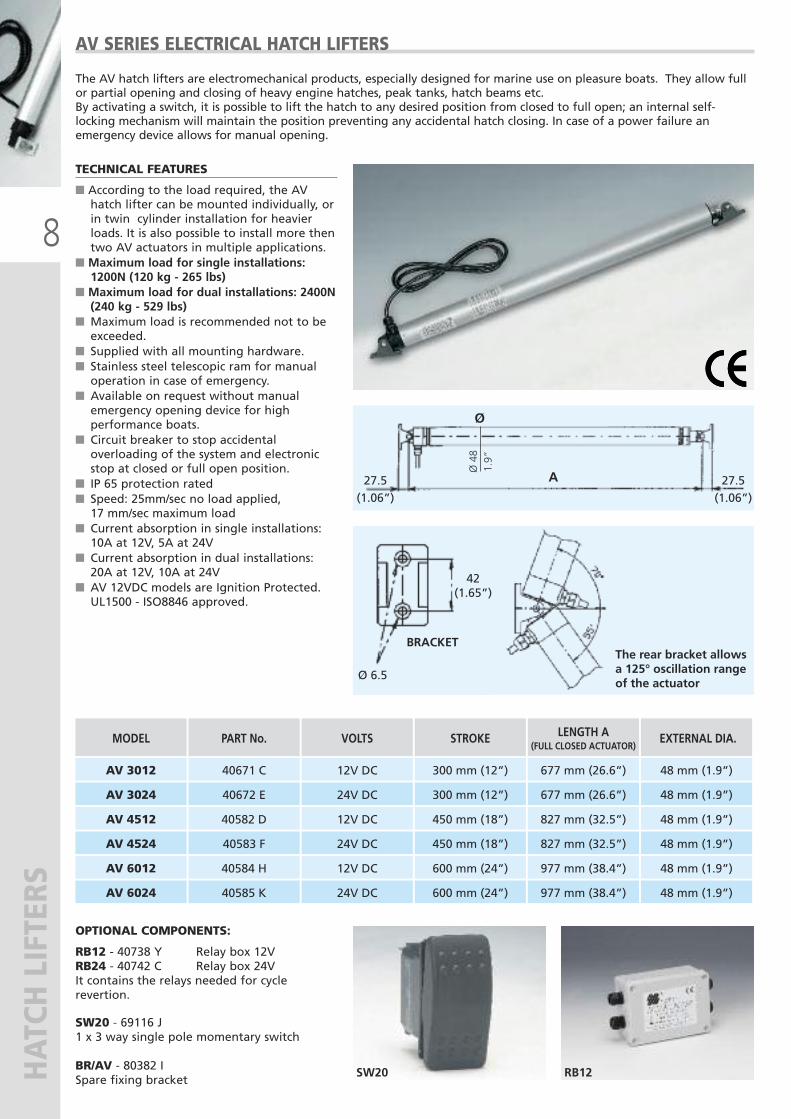
The AV hatch lifters are electromechanical products, especially designed for marine use on pleasure boats. They allow fullor partial opening and closing of heavy engine hatches, peak tanks, hatch beams etc. By activating a switch, it is possible to lift the hatch to any desired position from closed to full open; an internal self-locking mechanism will maintain the position preventing any accidental hatch closing. In case of a power failure anemergency device allows for manual opening.
AV SERIES ELECTRICAL HATCH LIFTERS
AV 3012 40671 C
40582 D
40584 H 12V DC
12V DC
12V DC
AV 4512
AV 6012
AV 3024 40672 E
40583 F
40585 K 24V DC
24V DC
24V DC
AV 4524
AV 6024
TECHNICAL FEATURES
� According to the load required, the AVhatch lifter can be mounted individually, orin twin cylinder installation for heavierloads. It is also possible to install more thentwo AV actuators in multiple applications.
� Maximum load for single installations:1200N (120 kg - 265 lbs)
� Maximum load for dual installations: 2400N(240 kg - 529 lbs)
� Maximum load is recommended not to beexceeded.
� Supplied with all mounting hardware.� Stainless steel telescopic ram for manualoperation in case of emergency.
� Available on request without manualemergency opening device for highperformance boats.
� Circuit breaker to stop accidentaloverloading of the system and electronicstop at closed or full open position.
� IP 65 protection rated� Speed: 25mm/sec no load applied, 17 mm/sec maximum load
� Current absorption in single installations:10A at 12V, 5A at 24V
� Current absorption in dual installations:20A at 12V, 10A at 24V
� AV 12VDC models are Ignition Protected.UL1500 - ISO8846 approved.
BRACKET
OPTIONAL COMPONENTS:
RB12 - 40738 Y Relay box 12VRB24 - 40742 C Relay box 24VIt contains the relays needed for cyclerevertion.
SW20 - 69116 J 1 x 3 way single pole momentary switch
BR/AV - 80382 ISpare fixing bracket
RB12SW20
48 mm (1.9”)600 mm (24”) 977 mm (38.4”)
450 mm (18”) 827 mm (32.5”) 48 mm (1.9”)
300 mm (12”) 677 mm (26.6”) 48 mm (1.9”)
600 mm (24”) 977 mm (38.4”) 48 mm (1.9”)
827 mm (32.5”)450 mm (18”) 48 mm (1.9”)
300 mm (12”) 677 mm (26.6”) 48 mm (1.9”)
The rear bracket allowsa 125° oscillation rangeof the actuator
9
HATCH LIFTERS
210.8”
421.6”
572.2”
14,50.6”
14,50.6”
150.6”
6,50.2”
6,50.2”
20 0.7”
7,
50.
3”
30 1.2”
7,5 0.3”
210.8”
Ø 3
4 1.
3”
A
MODEL PART No. VOLTS STROKE LENGTH A(FULL CLOSED ACTUATOR)
EXTERNAL DIA.
SW20
OPTIONAL COMPONENTS:
SW20 - 69116 J1 x 3 way single pole momentary switch
BR/UL - 35697 P Spare fixing bracket
ULYSSES 1812 40924 Q
40925 R 12V DC
12V DC
ULYSSES 3012
ULYSSES 1824 40926 S
40927 T 24V DC
24V DC
ULYSSES 3024
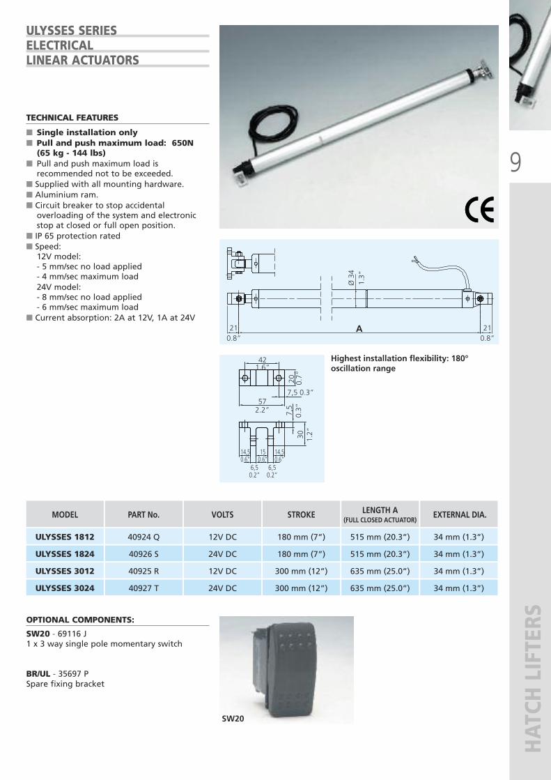
TECHNICAL FEATURES
� Single installation only� Pull and push maximum load: 650N(65 kg - 144 lbs)
� Pull and push maximum load isrecommended not to be exceeded.
� Supplied with all mounting hardware.� Aluminium ram.� Circuit breaker to stop accidentaloverloading of the system and electronicstop at closed or full open position.
� IP 65 protection rated� Speed:12V model:- 5 mm/sec no load applied- 4 mm/sec maximum load 24V model:- 8 mm/sec no load applied- 6 mm/sec maximum load
� Current absorption: 2A at 12V, 1A at 24V
Highest installation flexibility: 180°oscillation range
ULYSSES SERIESELECTRICALLINEAR ACTUATORS
300 mm (12”) 635 mm (25.0”) 34 mm (1.3”)
180 mm (7”) 515 mm (20.3”) 34 mm (1.3”)
635 mm (25.0”)300 mm (12”) 34 mm (1.3”)
180 mm (7”) 515 mm (20.3”) 34 mm (1.3”)
10
HATCH LIFTERS
Fig. 1 Fig. 2
Fig. 3 Fig. 4
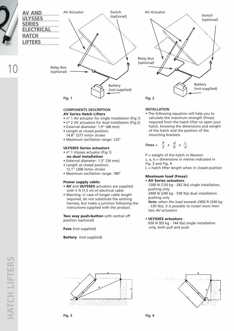
COMPONENTS DESCRIPTIONAV Series Hatch Lifters• nº 1 AV actuator for single installation (Fig.1)• nº 2 AV actuators for dual installation (Fig.2) • External diameter: 1.9” (48 mm)• Length at closed position: 14.8” (377 mm)+ stroke • Maximum oscillation range: 125°
ULYSSES Series actuators• nº 1 Ulysses actuator (Fig.1)no dual installation
• External diameter: 1.3” (34 mm) • Length at closed position: 12.1” (308 mm)+ stroke • Maximum oscillation range: 180°
Power supply cable:• AV and ULYSSES actuators are suppliedwith 5 ft (1,5 m) of electrical cable
• Warning: in case of longer cable lengthrequired, do not substitute the existingharness, but make a junction following theinstructions supplied with the product.
Two way push-button with central offposition (optional)
Fuse (not supplied)
Battery (not supplied)
INSTALLATION• The following equation will help you tocalculate the maximum strength (Fmax)required from the hatch lifter to open yourhatch, knowing the dimensions and weightof the hatch and the position of themounting brackets.
Fmax = P x d x L 2 b a
P = weight of the hatch in Newtonc, a, b = dimensions in metres indicated inFig. 3 and Fig. 4L = hatch lifter length when in closed position
Maximum load (Fmax):• AV Series actuators: 1200 N (120 kg - 265 lbs) single installation, pushing only 2400 N (240 kg - 530 lbs) dual installation pushing only Note: when the load exceeds 2400 N (240 kg - 530 lbs), it is possible to install more then two AV actuators
• ULYSSES actuators: 650 N (65 kg - 144 lbs) single installationonly, both pull and push
AV ANDULYSSESSERIESELECTRICALHATCHLIFTERS
AV Actuator
Relay Box(optional)
Battery(not supplied)
Switch(optional)
AV Actuator
Relay Box(optional)
Battery(not supplied)
Switch(optional)
11
GAS SPRINGS
12
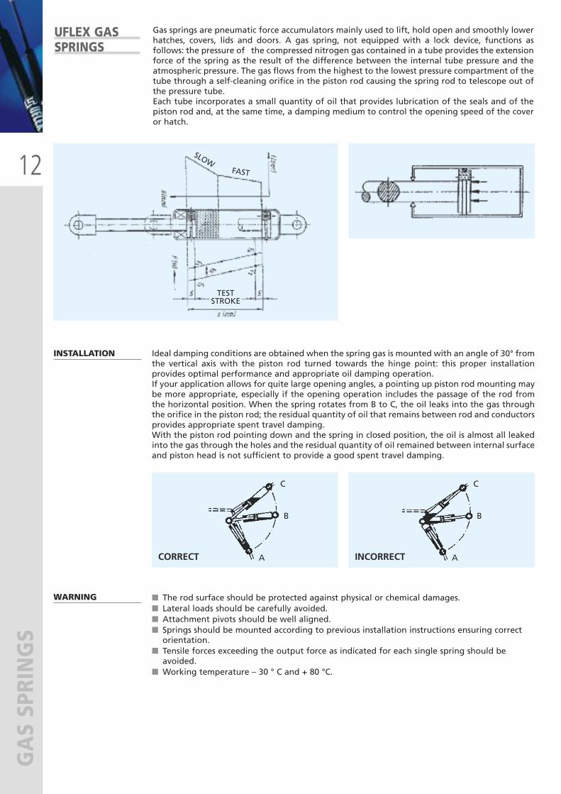
GAS SPRINGSGas springs are pneumatic force accumulators mainly used to lift, hold open and smoothly lowerhatches, covers, lids and doors. A gas spring, not equipped with a lock device, functions asfollows: the pressure of the compressed nitrogen gas contained in a tube provides the extensionforce of the spring as the result of the difference between the internal tube pressure and theatmospheric pressure. The gas flows from the highest to the lowest pressure compartment of thetube through a self-cleaning orifice in the piston rod causing the spring rod to telescope out ofthe pressure tube. Each tube incorporates a small quantity of oil that provides lubrication of the seals and of thepiston rod and, at the same time, a damping medium to control the opening speed of the coveror hatch.
UFLEX GASSPRINGS
INSTALLATION Ideal damping conditions are obtained when the spring gas is mounted with an angle of 30° fromthe vertical axis with the piston rod turned towards the hinge point: this proper installationprovides optimal performance and appropriate oil damping operation. If your application allows for quite large opening angles, a pointing up piston rod mounting maybe more appropriate, especially if the opening operation includes the passage of the rod fromthe horizontal position. When the spring rotates from B to C, the oil leaks into the gas throughthe orifice in the piston rod; the residual quantity of oil that remains between rod and conductorsprovides appropriate spent travel damping. With the piston rod pointing down and the spring in closed position, the oil is almost all leakedinto the gas through the holes and the residual quantity of oil remained between internal surfaceand piston head is not sufficient to provide a good spent travel damping.
WARNING � The rod surface should be protected against physical or chemical damages. � Lateral loads should be carefully avoided. � Attachment pivots should be well aligned. � Springs should be mounted according to previous installation instructions ensuring correctorientation.
� Tensile forces exceeding the output force as indicated for each single spring should beavoided.
� Working temperature – 30 ° C and + 80 °C.
TESTSTROKE
C
B
A
FAST
SLOW
CORRECT INCORRECT
C
B
A
13
GAS SPRINGS
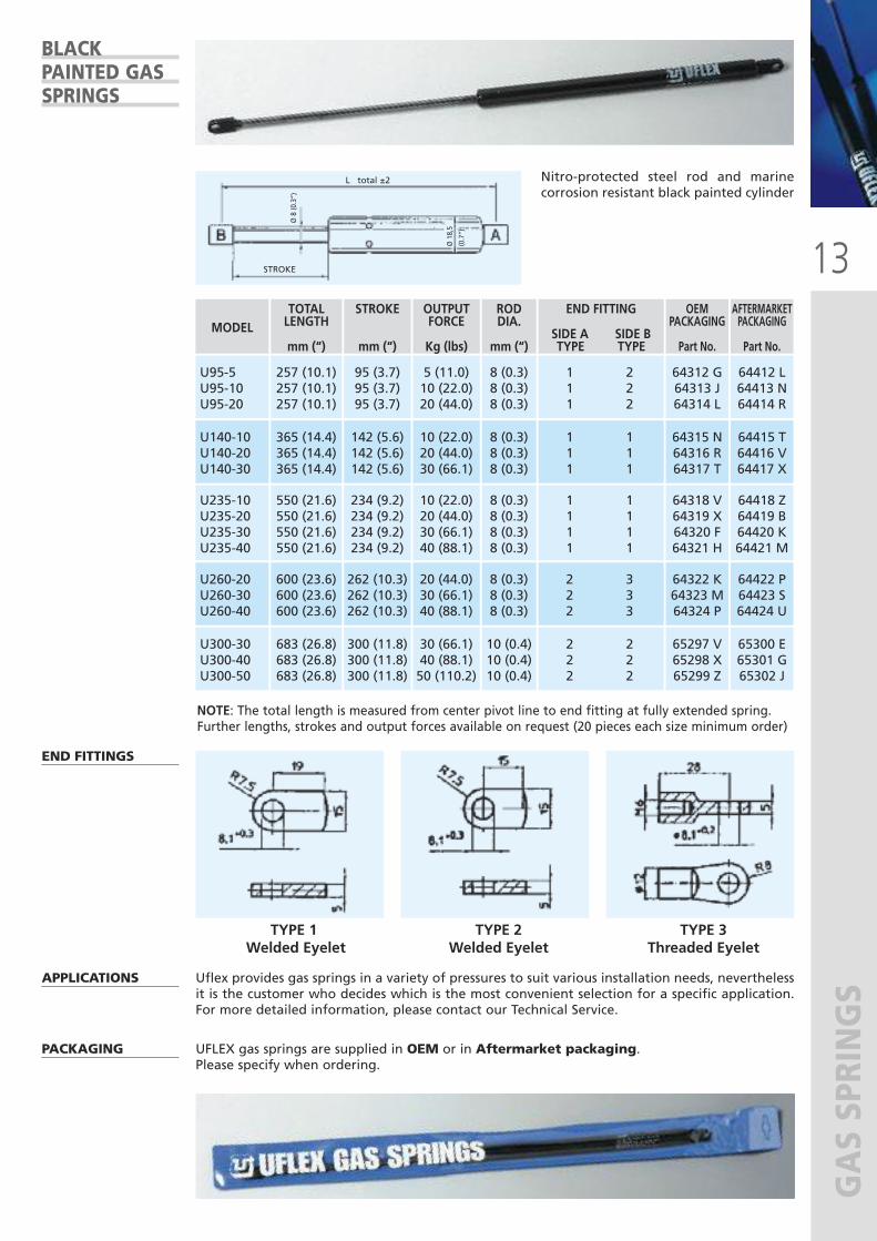
Nitro-protected steel rod and marinecorrosion resistant black painted cylinder
END FITTINGS
APPLICATIONS Uflex provides gas springs in a variety of pressures to suit various installation needs, neverthelessit is the customer who decides which is the most convenient selection for a specific application.For more detailed information, please contact our Technical Service.
PACKAGING UFLEX gas springs are supplied in OEM or in Aftermarket packaging. Please specify when ordering.
TYPE 1Welded Eyelet
TYPE 2 Welded Eyelet
TYPE 3Threaded Eyelet
BLACKPAINTED GASSPRINGS
NOTE: The total length is measured from center pivot line to end fitting at fully extended spring.Further lengths, strokes and output forces available on request (20 pieces each size minimum order)
STROKE
L total ±2
Ø 8 (0.3”)
Ø 18,5
(0.7”)
MODEL
U95-5U95-10U95-20
257 (10.1)257 (10.1)257 (10.1)
95 (3.7)95 (3.7)95 (3.7)
5 (11.0)10 (22.0)20 (44.0)
8 (0.3)8 (0.3)8 (0.3)
64412 L64413 N64414 R
1 2 1 2 1 2
U140-10U140-20U140-30
365 (14.4)365 (14.4)365 (14.4)
142 (5.6)142 (5.6)142 (5.6)
10 (22.0)20 (44.0)30 (66.1)
8 (0.3)8 (0.3)8 (0.3)
64415 T64416 V64417 X
1 1 1 1 1 1
U235-10U235-20U235-30U235-40
550 (21.6)550 (21.6)550 (21.6)550 (21.6)
234 (9.2)234 (9.2)234 (9.2)234 (9.2)
10 (22.0)20 (44.0)30 (66.1)40 (88.1)
8 (0.3)8 (0.3)8 (0.3)8 (0.3)
64418 Z64419 B64420 K64421 M
1 1 1 1 1 1 1 1
U260-20U260-30U260-40
600 (23.6)600 (23.6)600 (23.6)
262 (10.3)262 (10.3)262 (10.3)
20 (44.0)30 (66.1)40 (88.1)
8 (0.3)8 (0.3)8 (0.3)
64422 P64423 S64424 U
2 3 2 3 2 3
TOTAL LENGTH
mm (“)
STROKE
mm (“)
OUTPUTFORCE
Kg (lbs)
RODDIA.
mm (“)
END FITTING
SIDE A SIDE BTYPE TYPE
AFTERMARKETPACKAGING
Part No.
64312 G64313 J64314 L
64315 N64316 R64317 T
64318 V64319 X64320 F64321 H
64322 K64323 M64324 P
OEMPACKAGING
Part No.
U300-30U300-40U300-50
683 (26.8)683 (26.8)683 (26.8)
300 (11.8)300 (11.8)300 (11.8)
30 (66.1)40 (88.1)50 (110.2)
10 (0.4)10 (0.4)10 (0.4)
65300 E65301 G65302 J
2 2 2 2 2 2
65297 V65298 X65299 Z
14
GAS SPRINGS
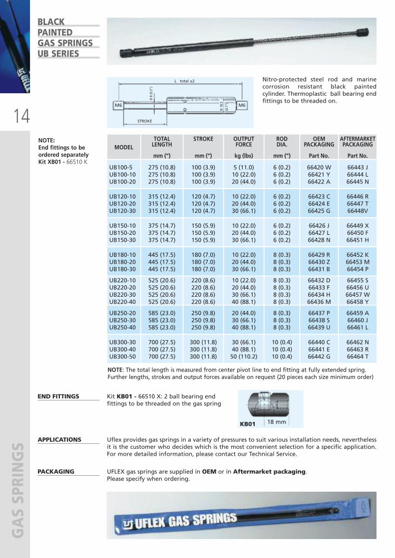
Nitro-protected steel rod and marinecorrosion resistant black paintedcylinder. Thermoplastic ball bearing endfittings to be threaded on.
END FITTINGS
APPLICATIONS Uflex provides gas springs in a variety of pressures to suit various installation needs, neverthelessit is the customer who decides which is the most convenient selection for a specific application.For more detailed information, please contact our Technical Service.
PACKAGING UFLEX gas springs are supplied in OEM or in Aftermarket packaging. Please specify when ordering.
BLACKPAINTEDGAS SPRINGSUB SERIES
NOTE: The total length is measured from center pivot line to end fitting at fully extended spring.Further lengths, strokes and output forces available on request (20 pieces each size minimum order)
NOTE: End fittings to beordered separatelyKit XB01 - 66510 K
STROKE
M6 M6
L total ±2
Ø 8 (0.3”)
Ø 18,5
(0.7”)
MODEL
UB100-5UB100-10UB100-20
275 (10.8)275 (10.8)275 (10.8)
100 (3.9)100 (3.9)100 (3.9)
5 (11.0)10 (22.0)20 (44.0)
6 (0.2)6 (0.2)6 (0.2)
66443 J66444 L66445 N
UB120-10UB120-20UB120-30
315 (12.4)315 (12.4)315 (12.4)
120 (4.7)120 (4.7)120 (4.7)
10 (22.0)20 (44.0)30 (66.1)
6 (0.2)6 (0.2)6 (0.2)
66446 R 66447 T 66448V
UB150-10UB150-20UB150-30
375 (14.7)375 (14.7)375 (14.7)
150 (5.9)150 (5.9)150 (5.9)
10 (22.0)20 (44.0)30 (66.1)
6 (0.2)6 (0.2)6 (0.2)
66449 X 66450 F 66451 H
UB180-10UB180-20UB180-30
445 (17.5)445 (17.5)445 (17.5)
180 (7.0)180 (7.0)180 (7.0)
10 (22.0)20 (44.0)30 (66.1)
8 (0.3)8 (0.3)8 (0.3)
66452 K 66453 M66454 P
TOTAL LENGTH
mm (“)
STROKE
mm (“)
OUTPUTFORCE
kg (lbs)
RODDIA.
mm (“)
AFTERMARKETPACKAGING
Part No.
66420 W66421 Y 66422 A
66423 C 66424 E66425 G
UB250-20UB250-30UB250-40
585 (23.0)585 (23.0)585 (23.0)
250 (9.8)250 (9.8)250 (9.8)
20 (44.0)30 (66.1)40 (88.1)
8 (0.3)8 (0.3)8 (0.3)
66459 A66460 J 66461 L
66437 P 66438 S 66439 U
UB300-30UB300-40UB300-50
700 (27.5)700 (27.5)700 (27.5)
300 (11.8)300 (11.8)300 (11.8)
30 (66.1)40 (88.1)50 (110.2)
10 (0.4)10 (0.4)10 (0.4)
66462 N66463 R 66464 T
66440 C66441 E 66442 G
66426 J66427 L 66428 N
66429 R 66430 Z66431 B
OEMPACKAGING
Part No.
UB220-10UB220-20UB220-30UB220-40
525 (20.6)525 (20.6)525 (20.6)525 (20.6)
220 (8.6)220 (8.6)220 (8.6)220 (8.6)
10 (22.0)20 (44.0)30 (66.1)40 (88.1)
8 (0.3)8 (0.3)8 (0.3)8 (0.3)
66455 S 66456 U 66457 W 66458 Y
66432 D 66433 F 66434 H 66436 M
18 mm
Kit KB01 - 66510 X: 2 ball bearing endfittings to be threaded on the gas spring
KB01
15
GAS SPRINGS
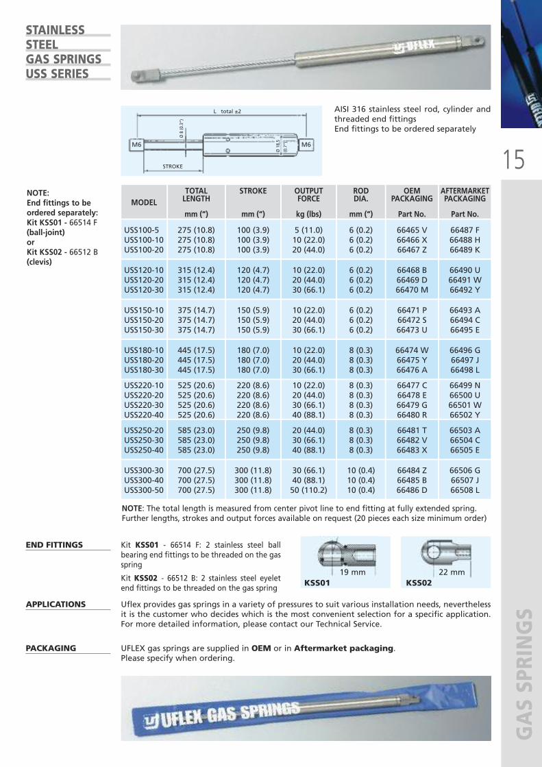
NOTE: End fittings to beordered separately:Kit KSS01 - 66514 F(ball-joint)orKit KSS02 - 66512 B(clevis)
STROKE
M6 M6
L total ±2
Ø 8 (0.3”)
Ø 18,5
(0.7”)
NOTE: The total length is measured from center pivot line to end fitting at fully extended spring.Further lengths, strokes and output forces available on request (20 pieces each size minimum order)
MODEL
USS100-5USS100-10USS100-20
275 (10.8)275 (10.8)275 (10.8)
100 (3.9)100 (3.9)100 (3.9)
5 (11.0)10 (22.0)20 (44.0)
6 (0.2)6 (0.2)6 (0.2)
66487 F 66488 H 66489 K
USS120-10USS120-20USS120-30
315 (12.4)315 (12.4)315 (12.4)
120 (4.7)120 (4.7)120 (4.7)
10 (22.0)20 (44.0)30 (66.1)
6 (0.2)6 (0.2)6 (0.2)
66490 U 66491 W 66492 Y
USS150-10USS150-20USS150-30
375 (14.7)375 (14.7)375 (14.7)
150 (5.9)150 (5.9)150 (5.9)
10 (22.0)20 (44.0)30 (66.1)
6 (0.2)6 (0.2)6 (0.2)
66493 A 66494 C66495 E
USS180-10USS180-20USS180-30
445 (17.5)445 (17.5)445 (17.5)
180 (7.0)180 (7.0)180 (7.0)
10 (22.0)20 (44.0)30 (66.1)
8 (0.3)8 (0.3)8 (0.3)
66496 G 66497 J66498 L
TOTAL LENGTH
mm (“)
STROKE
mm (“)
OUTPUTFORCE
kg (lbs)
RODDIA.
mm (“)
AFTERMARKETPACKAGING
Part No.
66465 V 66466 X66467 Z
66468 B 66469 D 66470 M
USS250-20USS250-30USS250-40
585 (23.0)585 (23.0)585 (23.0)
250 (9.8)250 (9.8)250 (9.8)
20 (44.0)30 (66.1)40 (88.1)
8 (0.3)8 (0.3)8 (0.3)
66503 A 66504 C 66505 E
66481 T 66482 V66483 X
USS300-30USS300-40USS300-50
700 (27.5)700 (27.5)700 (27.5)
300 (11.8)300 (11.8)300 (11.8)
30 (66.1)40 (88.1)50 (110.2)
10 (0.4)10 (0.4)10 (0.4)
66506 G 66507 J 66508 L
66484 Z 66485 B66486 D
66471 P 66472 S 66473 U
66474 W66475 Y66476 A
OEMPACKAGING
Part No.
USS220-10USS220-20USS220-30USS220-40
525 (20.6)525 (20.6)525 (20.6)525 (20.6)
220 (8.6)220 (8.6)220 (8.6)220 (8.6)
10 (22.0)20 (44.0)30 (66.1)40 (88.1)
8 (0.3)8 (0.3)8 (0.3)8 (0.3)
66499 N 66500 U66501 W 66502 Y
66477 C 66478 E66479 G 66480 R
AISI 316 stainless steel rod, cylinder andthreaded end fittingsEnd fittings to be ordered separately
APPLICATIONS Uflex provides gas springs in a variety of pressures to suit various installation needs, neverthelessit is the customer who decides which is the most convenient selection for a specific application.For more detailed information, please contact our Technical Service.
END FITTINGS
Kit KSS01 - 66514 F: 2 stainless steel ballbearing end fittings to be threaded on the gasspring
Kit KSS02 - 66512 B: 2 stainless steel eyeletend fittings to be threaded on the gas spring
PACKAGING UFLEX gas springs are supplied in OEM or in Aftermarket packaging. Please specify when ordering.
STAINLESSSTEELGAS SPRINGS USS SERIES
19 mm 22 mmKSS01 KSS02
16
GAS SPRINGS
12-0
.5”
3-0.1”
50-1.9” 7.5-
0.3“ 37
.6-1
.5”
33-1
.3”
50-1.9” 3-0.1”
37-1
.4”
8-0.
3”
25.2
-1,0
”
33-1
.3”
50-1.9” 3-0.1”
37-1
.4”
8-0.
3”
25.2
-1,0
”
12-0
.5”
3-0.1”
50-1.9” 7.5-
0.3“ 37
.6-1
.5”
33-1
.3”
50-1.9” 3-0.1”
37-1
.4”
8-0.
3”
25.2
-1,0
”
33-1
.3”
50-1.9” 3-0.1”
37-1
.4”
8-0.
3”
25.2
-1,0
”
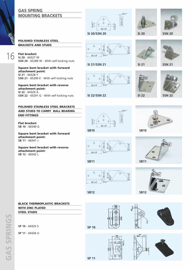
BLACK THERMOPLASTIC BRACKETS WITH ZINC PLATEDSTEEL STUDS
SP 10 - 64325 S
SP 11 - 64326 U
SP 10
SP 11
POLISHED STAINLESS STEEL BRACKETSAND STUDS TO CARRY BALL BEARINGEND FITTINGS
Flat bracket:SB 10 - 66540 G
Square bent bracket with forwardattachment point:SB 11 - 66541 J
Square bent bracket with reverseattachment point:SB 12 - 66542 L
GAS SPRINGMOUNTING BRACKETS
POLISHED STAINLESS STEELBRACKETS AND STUDS
Flat bracket:SI 20 - 64327 WSSN 20 - 65289 W - With self-locking nuts
Square bent bracket with forwardattachment point:SI 21 - 64328 YSSN 21 - 65290 E - With self-locking nuts
Square bent bracket with reverseattachment point:SI 22 - 64329 ASSN 22 - 65291 G - With self-locking nuts
SI 20/SSN 20
SI 21/SSN 21
SI 22/SSN 22
SB10
SB11
SB12
SI 20
SI 21
SI 22
SSN 20
SSN 21
SSN 22
SB10
SB11
SB12
17
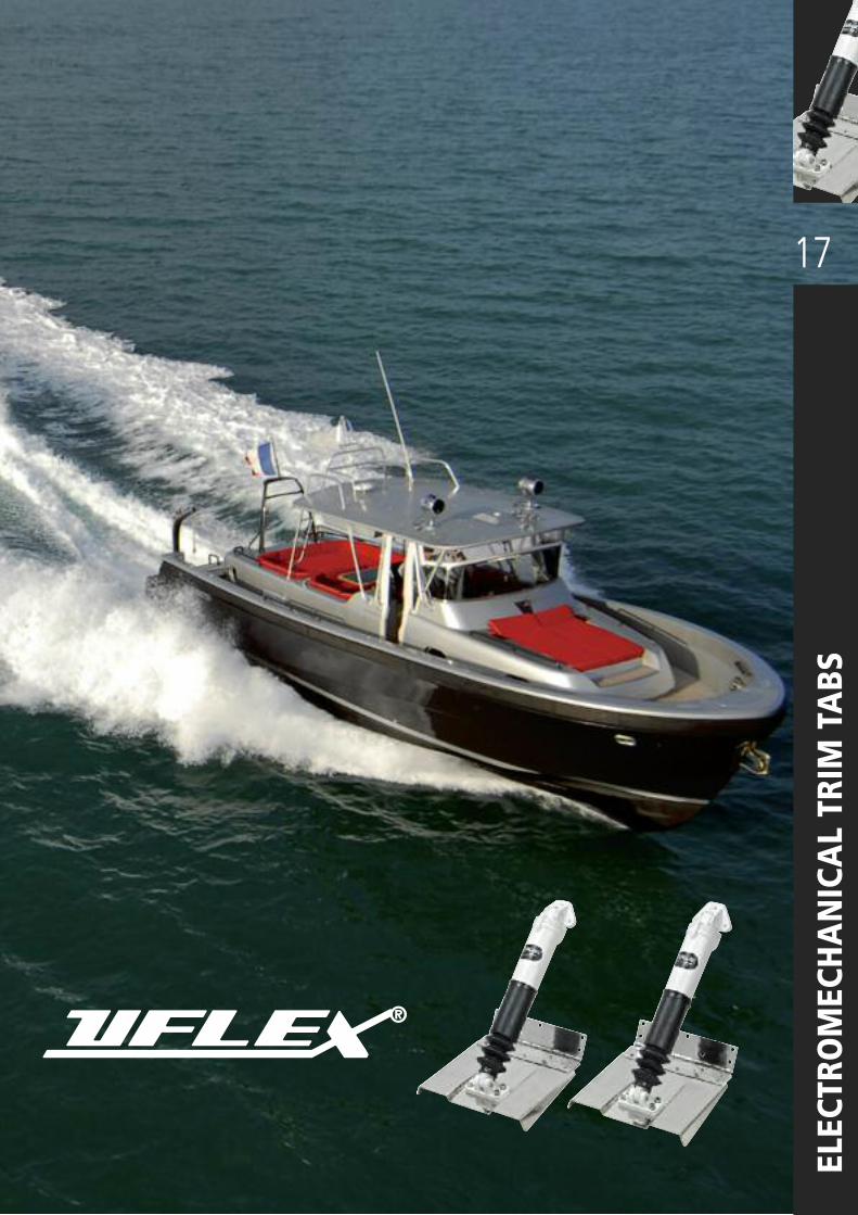
ELECTROMECHANICAL TRIM TABS
®
18
ELECTROMECHANICAL TRIM TABS
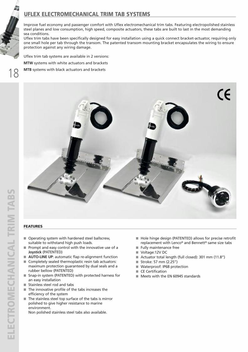
UFLEX ELECTROMECHANICAL TRIM TAB SYSTEMS
Improve fuel economy and passenger comfort with Uflex electromechanical trim tabs. Featuring electropolished stainlesssteel planes and low consumption, high speed, composite actuators, these tabs are built to last in the most demandingsea conditions. Uflex trim tabs have been specifically designed for easy installation using a quick connect bracket-actuator, requiring onlyone small hole per tab through the transom. The patented transom mounting bracket encapsulates the wiring to ensureprotection against any wiring damage.
Uflex trim tab systems are available in 2 versions:
MTW systems with white actuators and brackets
MTB systems with black actuators and brackets
FEATURES
� Operating system with hardened steel ballscrew,suitable to withstand high push loads.
� Prompt and easy control with the innovative use of aJoystick (PATENTED)
� AUTO-LINE UP: automatic flap re-alignment function� Completely sealed thermoplastic resin tab actuators:maximum protection guaranteed by dual seals and arubber bellow (PATENTED)
� Snap-in system (PATENTED) with protected harness foran easy installation
� Stainless steel rod and tabs� The innovative profile of the tabs increases theefficiency of the system
� The stainless steel top surface of the tabs is mirrorpolished to give higher resistance to marineenvironment.Non polished stainless steel tabs also available.
� Hole hinge design (PATENTED) allows for precise retrofitreplacement with Lenco® and Bennett® same size tabs
� Fully maintenance free� Voltage:12V DC� Actuator total length (full closed): 301 mm (11.8”)� Stroke: 57 mm (2.25”)� Waterproof: IP68 protection� CE Certification� Meets with the EN 60945 standards
19
ELECTROMECHANICAL TRIM TABS
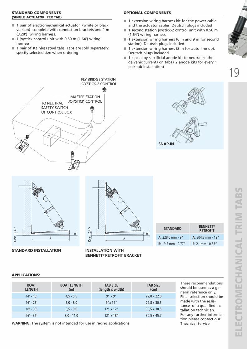
STANDARD COMPONENTS(SINGLE ACTUATOR PER TAB)
� 1 pair of electromechanical actuator (white or blackversion) complete with connection brackets and 1 m(3.28’) wiring harness.
� 1 joystick control unit with 0.50 m (1.64’) wiringharness
� 1 pair of stainless steel tabs. Tabs are sold separately:specify selected size when ordering
APPLICATIONS:
OPTIONAL COMPONENTS
� 1 extension wiring harness kit for the power cableand the actuator cables. Deutsch plugs included
� 1 second station joystick-2 control unit with 0.50 m(1.64’) wiring harness
� 1 extension wiring harness (6 m and 9 m for secondstation). Deutsch plugs included.
� 1 extension wiring harness (2 m for auto-line up).Deutsch plugs included.
� 1 zinc alloy sacrificial anode kit to neutralize thegalvanic currents on tabs ( 2 anode kits for every 1pair tab installation)
TO NEUTRALSAFETY SWITCHOF CONTROL BOX
MASTER STATIONJOYSTICK CONTROL
FLY BRIDGE STATIONJOYSTICK-2 CONTROL
These recommendationsshould be used as a ge-neral reference only.Final selection should bemade with the assis-tance of a qualified ins-tallation technician.For any further informa-tion please contact ourThecnical Service
14' - 18'
16' - 25'
BOATLENGTH
4,5 - 5,5
5,0 - 8,0
BOAT LENGTH(m)
9" x 9"
9"x 12"
TAB SIZE(length x width)
22,8 x 22,8
22,8 x 30,5
TAB SIZE (cm)
18' - 30'
26' - 36'
5,5 - 9,0
8,0 - 11,0
12" x 12"
12" x 18"
30,5 x 30,5
30,5 x 45,7
STANDARD INSTALLATION INSTALLATION WITH BENNETT® RETROFIT BRACKET
SNAP-IN
A: 228.6 mm - 9”
B: 19.5 mm - 0.77”
STANDARD
A: 304.8 mm - 12”
B: 21 mm - 0.83”
BENNETT®
RETROFIT
WARNING: The system is not intended for use in racing applications
20
ELECTROMECHANICAL TRIM TABS
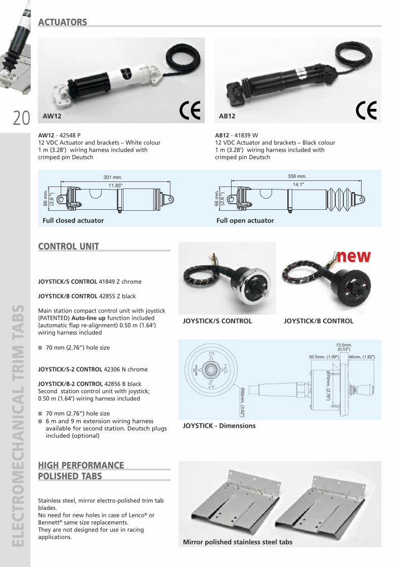
JOYSTICK/S CONTROL 41849 Z chrome
JOYSTICK/B CONTROL 42855 Z black
Main station compact control unit with joystick(PATENTED) Auto-line up function included(automatic flap re-alignment) 0.50 m (1.64’)wiring harness included
� 70 mm (2.76”) hole size
JOYSTICK/S-2 CONTROL 42306 N chrome
JOYSTICK/B-2 CONTROL 42856 B blackSecond station control unit with joystick;0.50 m (1.64’) wiring harness included
� 70 mm (2.76”) hole size� 6 m and 9 m extension wiring harnessavailable for second station. Deutsch plugsincluded (optional)
CONTROL UNIT
ACTUATORS
JOYSTICK/S CONTROL
AW12
JOYSTICK - Dimensions
Full open actuatorFull closed actuator
AW12 - 42548 P12 VDC Actuator and brackets – White colour1 m (3.28’) wiring harness included withcrimped pin Deutsch
AB12 - 41839 W12 VDC Actuator and brackets – Black colour1 m (3.28’) wiring harness included withcrimped pin Deutsch
AB12
Stainless steel, mirror electro-polished trim tabblades. No need for new holes in case of Lenco® orBennett® same size replacements.They are not designed for use in racingapplications.
HIGH PERFORMANCEPOLISHED TABS
JOYSTICK/B CONTROL
Mirror polished stainless steel tabs
new new
21
ELECTROMECHANICAL TRIM TABS
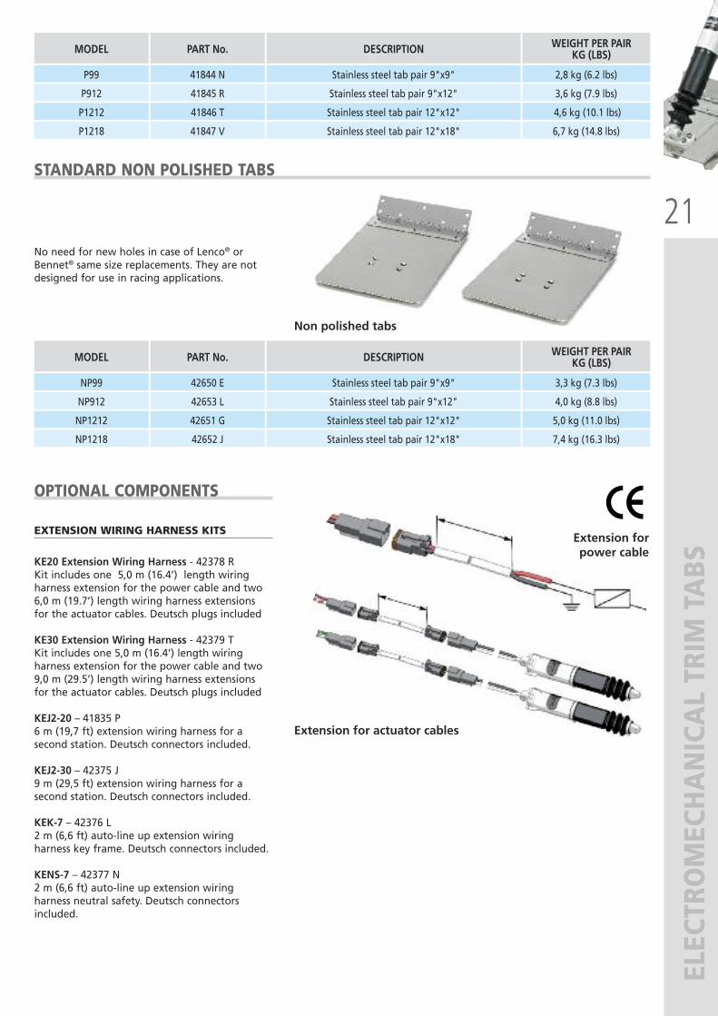
EXTENSION WIRING HARNESS KITS
KE20 Extension Wiring Harness - 42378 R Kit includes one 5,0 m (16.4’) length wiringharness extension for the power cable and two6,0 m (19.7’) length wiring harness extensionsfor the actuator cables. Deutsch plugs included
KE30 Extension Wiring Harness - 42379 T Kit includes one 5,0 m (16.4’) length wiringharness extension for the power cable and two9,0 m (29.5’) length wiring harness extensionsfor the actuator cables. Deutsch plugs included
KEJ2-20 – 41835 P6 m (19,7 ft) extension wiring harness for asecond station. Deutsch connectors included.
KEJ2-30 – 42375 J9 m (29,5 ft) extension wiring harness for asecond station. Deutsch connectors included.
KEK-7 – 42376 L2 m (6,6 ft) auto-line up extension wiringharness key frame. Deutsch connectors included.
KENS-7 – 42377 N2 m (6,6 ft) auto-line up extension wiringharness neutral safety. Deutsch connectorsincluded.
OPTIONAL COMPONENTS
Extension for actuator cables
Extension forpower cable
NP99
NP912
MODEL
42650 E
42653 L
PART No.
Stainless steel tab pair 9"x9"
Stainless steel tab pair 9"x12"
DESCRIPTION
3,3 kg (7.3 lbs)
4,0 kg (8.8 lbs)
WEIGHT PER PAIRKG (LBS)
NP1212
NP1218
42651 G
42652 J
Stainless steel tab pair 12"x12"
Stainless steel tab pair 12"x18"
5,0 kg (11.0 lbs)
7,4 kg (16.3 lbs)
STANDARD NON POLISHED TABS
No need for new holes in case of Lenco® orBennet® same size replacements. They are notdesigned for use in racing applications.
Non polished tabs
P99
P912
MODEL
41844 N
41845 R
PART No.
Stainless steel tab pair 9"x9"
Stainless steel tab pair 9"x12"
DESCRIPTION
2,8 kg (6.2 lbs)
3,6 kg (7.9 lbs)
WEIGHT PER PAIRKG (LBS)
P1212
P1218
41846 T
41847 V
Stainless steel tab pair 12"x12"
Stainless steel tab pair 12"x18"
4,6 kg (10.1 lbs)
6,7 kg (14.8 lbs)
22
ELECTROMECHANICAL TRIM TABS
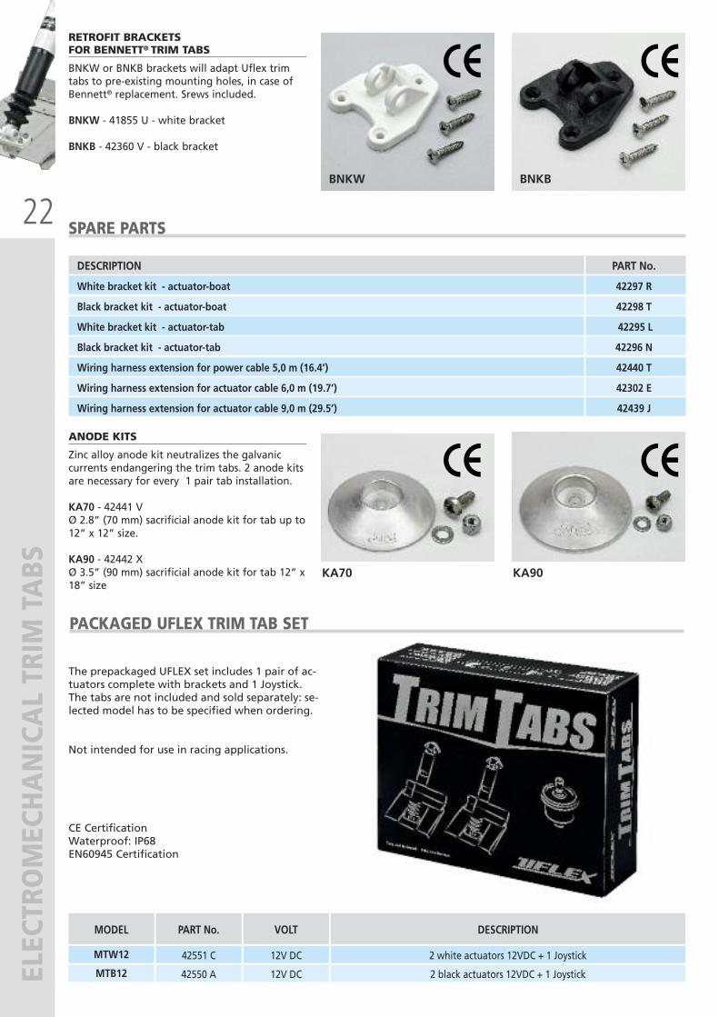
ANODE KITS
Zinc alloy anode kit neutralizes the galvaniccurrents endangering the trim tabs. 2 anode kitsare necessary for every 1 pair tab installation.
KA70 - 42441 VØ 2.8” (70 mm) sacrificial anode kit for tab up to12” x 12” size.
KA90 - 42442 X Ø 3.5” (90 mm) sacrificial anode kit for tab 12” x18” size
KA70 KA90
PACKAGED UFLEX TRIM TAB SET
The prepackaged UFLEX set includes 1 pair of ac-tuators complete with brackets and 1 Joystick.The tabs are not included and sold separately: se-lected model has to be specified when ordering.
Not intended for use in racing applications.
CE CertificationWaterproof: IP68EN60945 Certification
MTW12
MODEL
42551 C
PART No.
2 white actuators 12VDC + 1 Joystick
DESCRIPTION
MTB12 42550 A
12V DC
VOLT
12V DC 2 black actuators 12VDC + 1 Joystick
RETROFIT BRACKETSFOR BENNETT® TRIM TABS
BNKW or BNKB brackets will adapt Uflex trimtabs to pre-existing mounting holes, in case ofBennett® replacement. Srews included.
BNKW - 41855 U - white bracket
BNKB - 42360 V - black bracket
BNKW BNKB
SPARE PARTS
DESCRIPTION PART No.
White bracket kit - actuator-boat 42297 R
Black bracket kit - actuator-boat 42298 T
White bracket kit - actuator-tab 42295 L
Black bracket kit - actuator-tab 42296 N
Wiring harness extension for power cable 5,0 m (16.4’) 42440 T
Wiring harness extension for actuator cable 6,0 m (19.7’) 42302 E
Wiring harness extension for actuator cable 9,0 m (29.5’) 42439 J

23
ELECTROHYDRA
ULIC TRIM TABS
24
ELECTROHYDRA
ULIC TRIM TABS
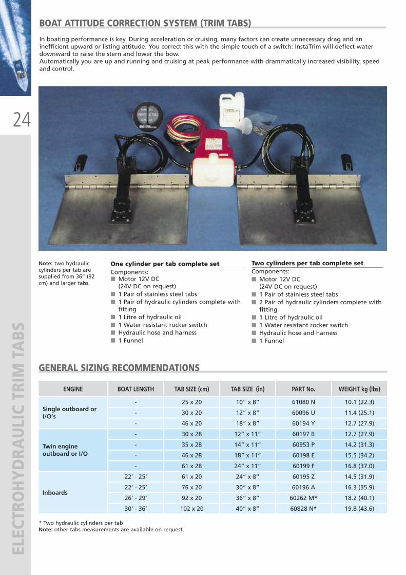
In boating performance is key. During acceleration or cruising, many factors can create unnecessary drag and aninefficient upward or listing attitude. You correct this with the simple touch of a switch: InstaTrim will deflect waterdownward to raise the stern and lower the bow. Automatically you are up and running and crui sing at peak performance with drammatically increased visibility, speedand control.
BOAT ATTITUDE CORRECTION SYSTEM (TRIM TABS)
One cylinder per tab complete set Components:� Motor 12V DC (24V DC on request)� 1 Pair of stainless steel tabs� 1 Pair of hydraulic cylinders complete with fitting � 1 Litre of hydraulic oil� 1 Water resistant rocker switch� Hydraulic hose and harness� 1 Funnel
Two cylinders per tab complete set Components:� Motor 12V DC (24V DC on request)
� 1 Pair of stainless steel tabs� 2 Pair of hydraulic cylinders complete with fitting� 1 Litre of hydraulic oil� 1 Water resistant rocker switch� Hydraulic hose and harness� 1 Funnel
GENERAL SIZING RECOMMENDATIONS
* Two hydraulic cylinders per tabNote: other tabs measurements are available on request.
Note: two hydrauliccylinders per tab aresupplied from 36” (92cm) and larger tabs.
ENGINE BOAT LENGTH
Single outboard orI/O’s
TAB SIZE (cm)
30 x 20
46 x 20
12” x 8”
18” x 8”
60096 U
60194 Y
-
25 x 20 10” x 8” 61080 N
11.4 (25.1)
12.7 (27.9)
10.1 (22.3) -
-
30 x 28
46 x 28
12” x 11”
18” x 11”
60197 B 12.7 (27.9)
14.2 (31.3)
15.5 (34.2)
16.8 (37.0)
60198 E
-
35 x 28 14” x 11” 60953 P-
-
61 x 28 24” x 11” 60199 F-
TAB SIZE (in) PART No. WEIGHT kg (lbs)
Twin engineoutboard or I/O
61 x 20
76 x 20
24” x 8”
30” x 8”
60195 Z 14.5 (31.9)
16.3 (35.9)
18.2 (40.1)
19.8 (43.6)
60196 A
22’ - 25’
22’ - 25’
92 x 20 36” x 8” 60262 M*26’ - 29’
102 x 20 40” x 8” 60828 N*30’ - 36’
Inboards
25
ELECTROHYDRA
ULIC TRIM TABS
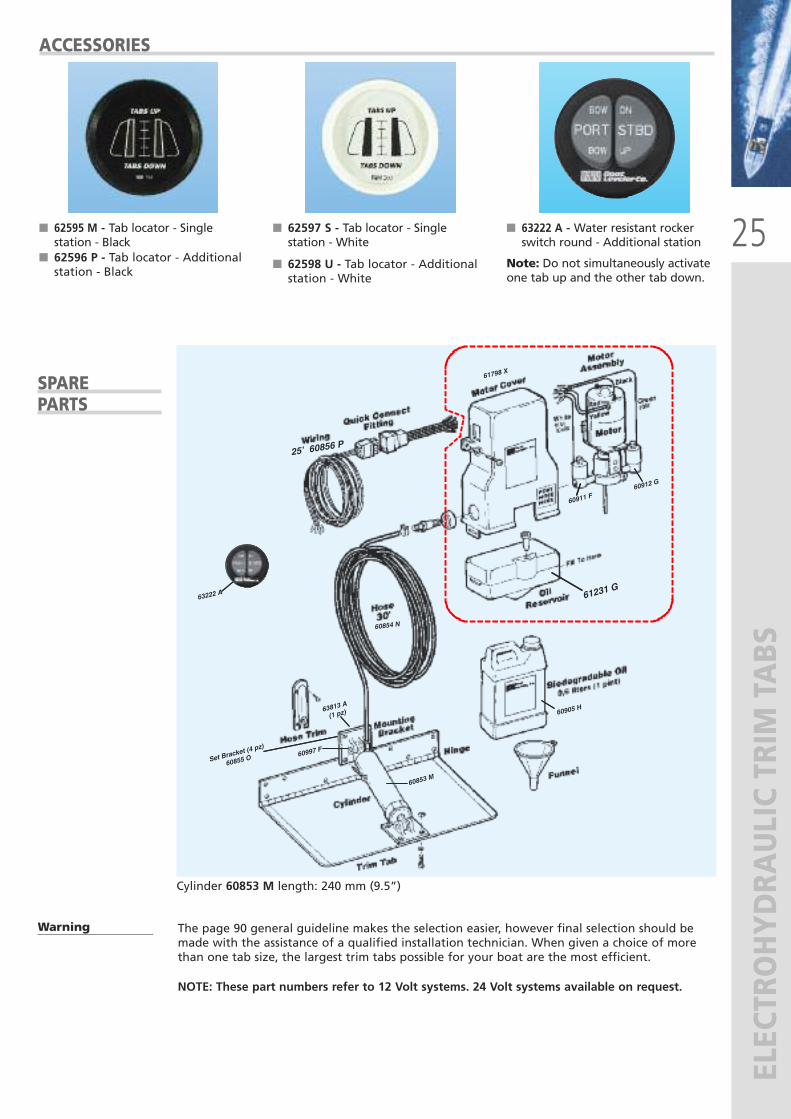
The page 90 general guideline makes the selection easier, however final selection should bemade with the assistance of a qualified installation technician. When given a choice of morethan one tab size, the largest trim tabs possible for your boat are the most efficient.
NOTE: These part numbers refer to 12 Volt systems. 24 Volt systems available on request.
ACCESSORIES
� 62595 M - Tab locator - Singlestation - Black
� 62596 P - Tab locator - Additionalstation - Black
� 63222 A - Water resistant rockerswitch round - Additional station
Note: Do not simultaneously activateone tab up and the other tab down.
� 62597 S - Tab locator - Singlestation - White
� 62598 U - Tab locator - Additionalstation - White
SPARE PARTS
Warning
Cylinder 60853 M length: 240 mm (9.5”)
63222 A
60997 F
60853 M
63813 A
(1 pz)
Set Bracke
t (4 pz)
60855 O
60905 H
61798 X
60912 G
60911 F
25’ 60856 P
60854 N
61231 G
26
ELECTROHYDRA
ULIC TRIM TABS
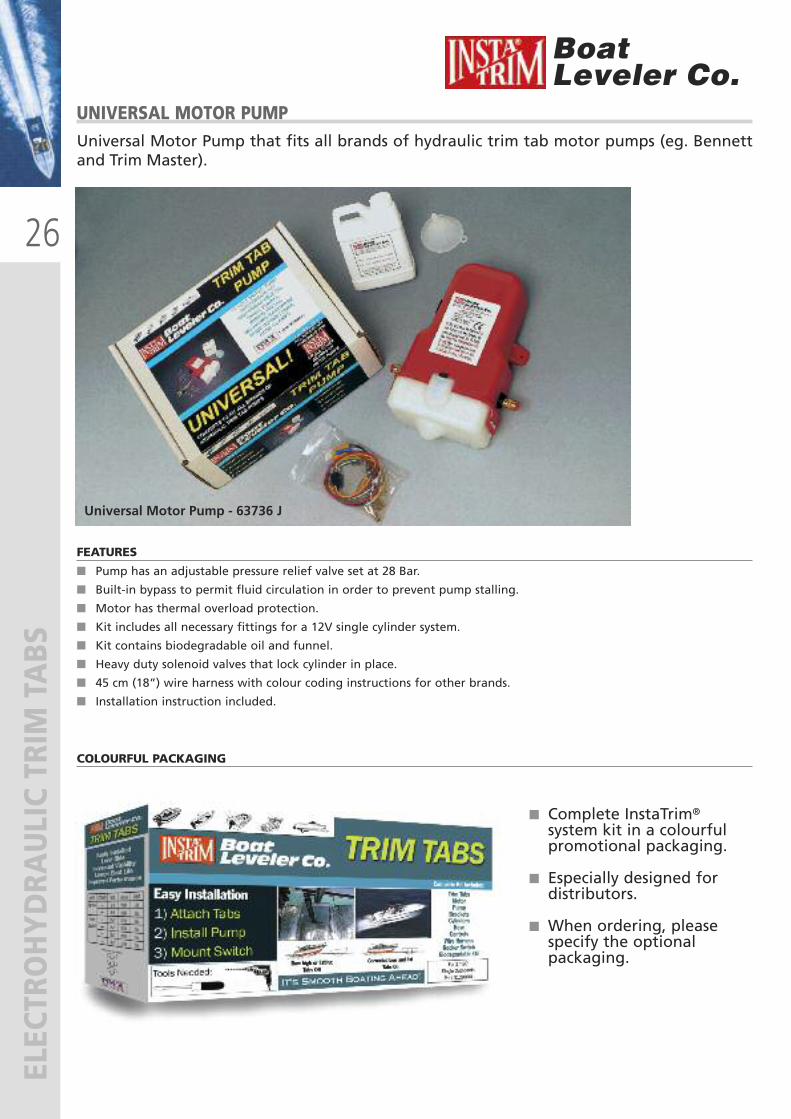
UNIVERSAL MOTOR PUMPUniversal Motor Pump that fits all brands of hydraulic trim tab motor pumps (eg. Bennettand Trim Master).
BoatLeveler Co.
FEATURES
� Pump has an adjustable pressure relief valve set at 28 Bar.
� Built-in bypass to permit fluid circulation in order to prevent pump stalling.
� Motor has thermal overload protection.
� Kit includes all necessary fittings for a 12V single cylinder system.
� Kit contains biodegradable oil and funnel.
� Heavy duty solenoid valves that lock cylinder in place.
� 45 cm (18”) wire harness with colour coding instructions for other brands.
� Installation instruction included.
� Complete InstaTrim® system kit in a colourful promotional packaging.
� Especially designed for distributors.
� When ordering, please specify the optional packaging.
COLOURFUL PACKAGING
Universal Motor Pump - 63736 J

products with a watertight reputation
®
27
WATERPRO
OF MARINE SYSTEM
S
28
WATERPRO
OF MARINE SYSTEM
S
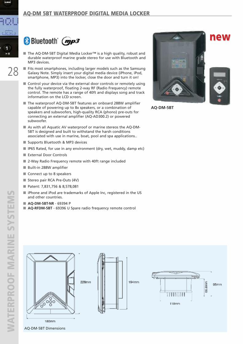
� The AQ-DM-5BT Digital Media Locker™ is a high quality, robust anddurable waterproof marine grade stereo for use with Bluetooth andMP3 devices.
� Fits most smartphones, including larger models such as the SamsungGalaxy Note. Simply insert your digital media device (iPhone, iPod,smartphone, MP3) into the locker, close the door and turn it on!
� Control your device via the external door controls or remotely usingthe fully waterproof, floating 2-way RF (Radio Frequency) remotecontrol. The remote has a range of 40ft and displays song and trackinformation on the LCD screen.
� The waterproof AQ-DM-5BT features an onboard 288W amplifiercapable of powering up to 8x speakers, or a combination ofspeakers and subwoofers, high-quality RCA (phono) pre-outs forconnecting an external amplifier (AQ-AD300.2) or poweredsubwoofer.
� As with all Aquatic AV waterproof or marine stereos the AQ-DM-5BT is designed and built to withstand the harsh conditionsassociated with use in marine, boat, pool and spa applications..
� Supports Bluetooth & MP3 devices
� IP65 Rated, for use in any environment (dry, wet, muddy, damp etc)
� External Door Controls
� 2-Way Radio Frequency remote with 40ft range included
� Built-in 288W amplifier
� Connect up to 8 speakers
� Stereo pair RCA Pre-Outs (4V)
� Patent: 7,831,756 & 8,578,081
� iPhone and iPod are trademarks of Apple Inc, registered in the USand other countries.
� AQ-DM-5BT-NR - 69394 P � AQ-RFDM-5BT - 69396 U Spare radio frequency remote control
AQ-DM 5BT WATERPROOF DIGITAL MEDIA LOCKER
AQ-DM-5BT
AQ-DM-5BT Dimensions
new new
29
WATERPRO
OF MARINE SYSTEM
S
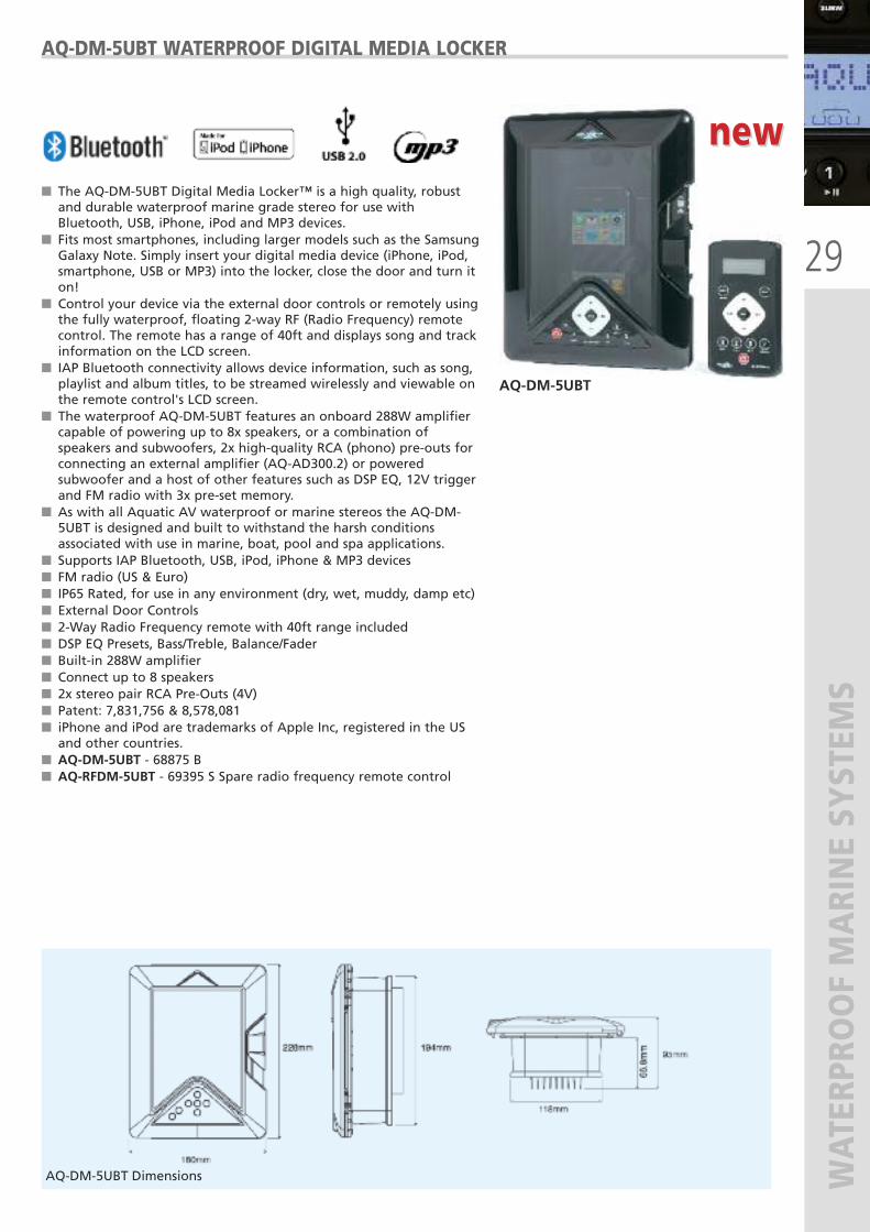
� The AQ-DM-5UBT Digital Media Locker™ is a high quality, robustand durable waterproof marine grade stereo for use withBluetooth, USB, iPhone, iPod and MP3 devices.
� Fits most smartphones, including larger models such as the SamsungGalaxy Note. Simply insert your digital media device (iPhone, iPod,smartphone, USB or MP3) into the locker, close the door and turn iton!
� Control your device via the external door controls or remotely usingthe fully waterproof, floating 2-way RF (Radio Frequency) remotecontrol. The remote has a range of 40ft and displays song and trackinformation on the LCD screen.
� IAP Bluetooth connectivity allows device information, such as song,playlist and album titles, to be streamed wirelessly and viewable onthe remote control's LCD screen.
� The waterproof AQ-DM-5UBT features an onboard 288W amplifiercapable of powering up to 8x speakers, or a combination ofspeakers and subwoofers, 2x high-quality RCA (phono) pre-outs forconnecting an external amplifier (AQ-AD300.2) or poweredsubwoofer and a host of other features such as DSP EQ, 12V triggerand FM radio with 3x pre-set memory.
� As with all Aquatic AV waterproof or marine stereos the AQ-DM-5UBT is designed and built to withstand the harsh conditionsassociated with use in marine, boat, pool and spa applications.
� Supports IAP Bluetooth, USB, iPod, iPhone & MP3 devices� FM radio (US & Euro)� IP65 Rated, for use in any environment (dry, wet, muddy, damp etc)� External Door Controls� 2-Way Radio Frequency remote with 40ft range included� DSP EQ Presets, Bass/Treble, Balance/Fader� Built-in 288W amplifier� Connect up to 8 speakers� 2x stereo pair RCA Pre-Outs (4V)� Patent: 7,831,756 & 8,578,081� iPhone and iPod are trademarks of Apple Inc, registered in the USand other countries.
� AQ-DM-5UBT - 68875 B� AQ-RFDM-5UBT - 69395 S Spare radio frequency remote control
AQ-DM-5UBT WATERPROOF DIGITAL MEDIA LOCKER
AQ-DM-5UBT
AQ-DM-5UBT Dimensions
new new
30
WATERPRO
OF MARINE SYSTEM
S
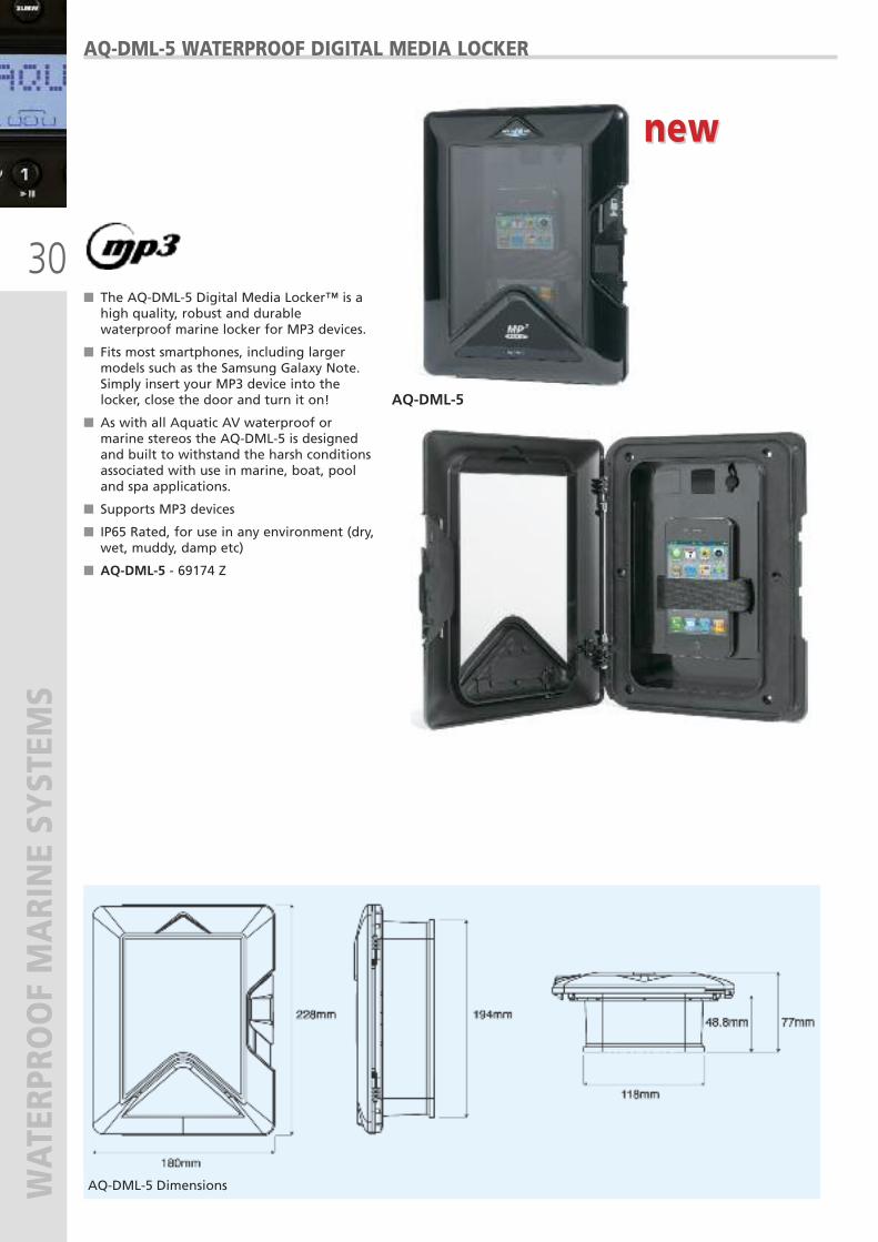
� The AQ-DML-5 Digital Media Locker™ is ahigh quality, robust and durablewaterproof marine locker for MP3 devices.
� Fits most smartphones, including largermodels such as the Samsung Galaxy Note.Simply insert your MP3 device into thelocker, close the door and turn it on!
� As with all Aquatic AV waterproof ormarine stereos the AQ-DML-5 is designedand built to withstand the harsh conditionsassociated with use in marine, boat, pooland spa applications.
� Supports MP3 devices
� IP65 Rated, for use in any environment (dry,wet, muddy, damp etc)
� AQ-DML-5 - 69174 Z
AQ-DML-5 WATERPROOF DIGITAL MEDIA LOCKER
AQ-DML-5
AQ-DML-5 Dimensions
new new
31
WATERPRO
OF MARINE SYSTEM
S
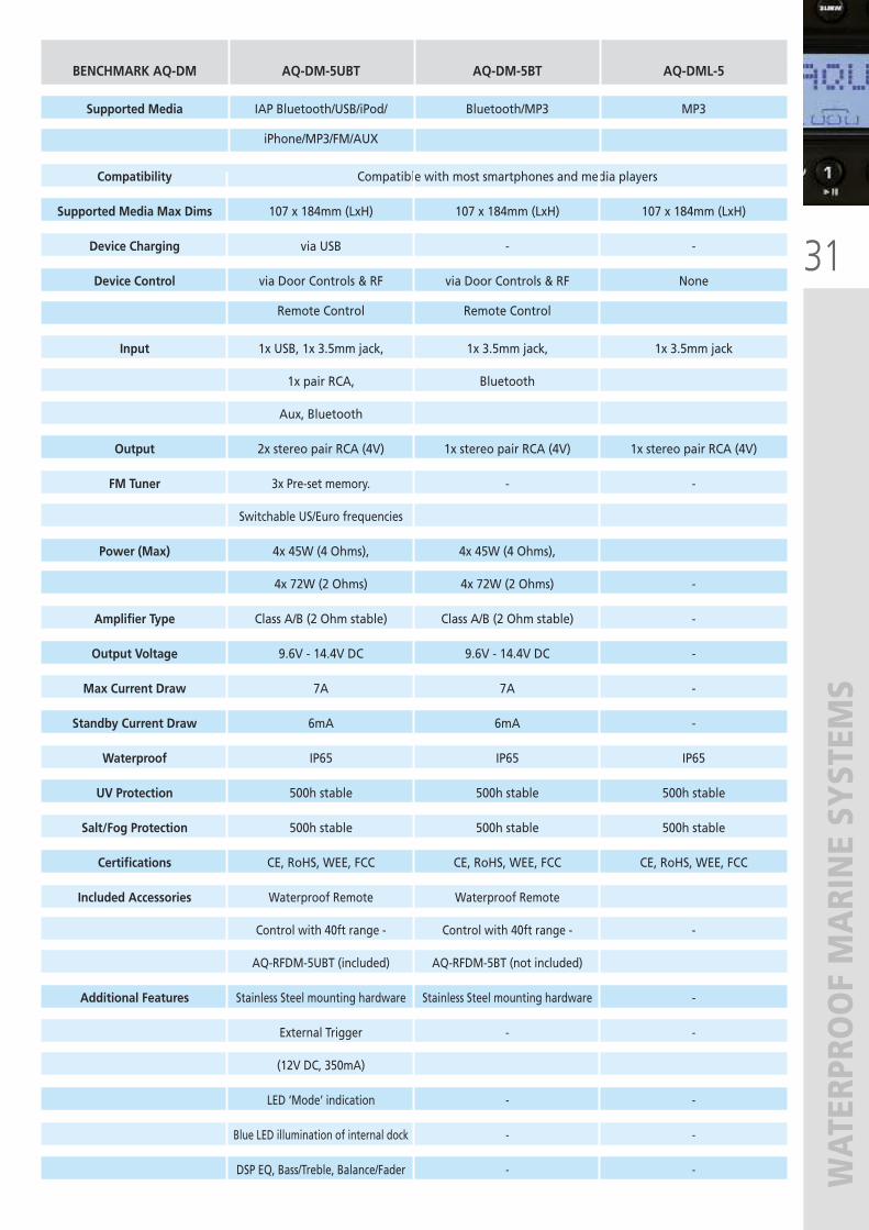
BENCHMARK AQ-DM AQ-DM-5UBT AQ-DM-5BT AQ-DML-5
Supported Media IAP Bluetooth/USB/iPod/ Bluetooth/MP3 MP3
iPhone/MP3/FM/AUX
Compatibility Compatible with most smartphones and media players
Supported Media Max Dims 107 x 184mm (LxH) 107 x 184mm (LxH) 107 x 184mm (LxH)
Device Charging via USB - -
Device Control via Door Controls & RF via Door Controls & RF None
Remote Control Remote Control
Input 1x USB, 1x 3.5mm jack, 1x 3.5mm jack, 1x 3.5mm jack
1x pair RCA, Bluetooth
Aux, Bluetooth
Output 2x stereo pair RCA (4V) 1x stereo pair RCA (4V) 1x stereo pair RCA (4V)
FM Tuner 3x Pre-set memory. - -
Switchable US/Euro frequencies
Power (Max) 4x 45W (4 Ohms), 4x 45W (4 Ohms),
4x 72W (2 Ohms) 4x 72W (2 Ohms) -
Amplifier Type Class A/B (2 Ohm stable) Class A/B (2 Ohm stable) -
Output Voltage 9.6V - 14.4V DC 9.6V - 14.4V DC -
Max Current Draw 7A 7A -
Standby Current Draw 6mA 6mA -
Waterproof IP65 IP65 IP65
UV Protection 500h stable 500h stable 500h stable
Salt/Fog Protection 500h stable 500h stable 500h stable
Certifications CE, RoHS, WEE, FCC CE, RoHS, WEE, FCC CE, RoHS, WEE, FCC
Included Accessories Waterproof Remote Waterproof Remote
Control with 40ft range - Control with 40ft range - -
AQ-RFDM-5UBT (included) AQ-RFDM-5BT (not included)
Additional Features Stainless Steel mounting hardware Stainless Steel mounting hardware -
External Trigger - -
(12V DC, 350mA)
LED ‘Mode’ indication - -
Blue LED illumination of internal dock - -
DSP EQ, Bass/Treble, Balance/Fader - -
32
WATERPRO
OF MARINE SYSTEM
S
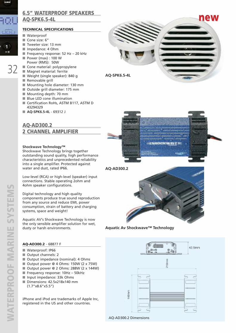
Shockwave Technology™Shockwave Technology brings togetheroutstanding sound quality, high performancecharacteristics and unprecedented reliabilityinto a single amplifier. Protected againstwater and dust, rated IP66.
Low-level (RCA) or high-level (speaker) inputconnections. Stable operating 2ohm and4ohm speaker configurations.
Digital technology and high qualitycomponents produce true sound reproductionfrom any source and reduce EMI, powerconsumption, strain of battery and chargingsystems, space and weight!
Aquatic AV’s Shockwave Technology is nowthe only sensible amplifier solution for wet,dusty or harsh environments.
AQ-AD300.2 - 68877 F
� Waterproof: IP66� Output channels: 2� Output impedance (nominal): 4 Ohms� Output power @ 4 Ohms: 150W (2 x 75W)� Output power @ 2 Ohms: 288W (2 x 144W)� Frequency response: 10Hz – 50kHz� Input impedance: 33k Ohms� Dimensions: 42.5x218x140 mm(1.7”x8.6”x5.5”)
iPhone and iPod are trademarks of Apple Inc,registered in the US and other countries.
AQ-AD300.22 CHANNEL AMPLIFIER
AQ-AD300.2 Dimensions
Aquatic Av Shockwave™ Technology
TECHNICAL SPECIFICATIONS
� Waterproof� Cone size: 6”� Tweeter size: 13 mm� Impedance: 4 Ohm� Frequency response: 52 Hz – 20 kHz� Power (max) : 100 WPower (RMS): 50W
� Cone material: polypropylene� Magnet material: ferrite� Weight (single speaker): 840 g� Removable grill� Mounting hole diameter: 130 mm� Outside grill diameter: 175 mm� Mounting depth: 70 mm� Blue LED cone illumination� Certification RoHs, ASTM B117, ASTM D43294329
� AQ-SPK6.5-4L - 69312 J
6.5” WATERPROOF SPEAKERSAQ-SPK6.5-4L
AQ-SPK6.5-4L
AQ-AD300.2
new new
33
MAGNETIC COMPASSES
34
MAGNETIC COMPASSES
RITCHIE® MAGNETIC COMPASSES
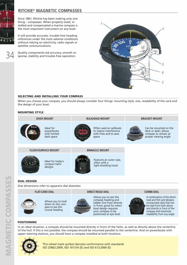
Since 1861, Ritchie has been making only onething – compasses. When properly sized, in-stalled and compensated a marine compass isthe most important instrument on any boat.
It will provide accurate, trouble-free headingreferences under the most adverse conditionswithout relying on electricity, radio signals orsatellite communications.
Quality components aid accuracy, smooth re-sponse, stability and trouble-free operation.
SELECTING AND INSTALLING YOUR COMPASS
When you choose your compass, you should always consider four things: mounting style, size, readability of the card andthe design of your boat.
POSITIONING
In an ideal situation, a compass should be mounted directly in front of the helm, as well as directly above the centerlineof the hull. If this is not possible, the compass should be mounted parallel to the centerline. And on powerboats withupper steering stations, you should have a compass installed at both locations.
MOUNTING STYLE
DASH MOUNT BULKHEAD MOUNT BRACKET MOUNT
Ideal for powerboats with limited dash space
Often used on sailboatsto reduce interferencewith lines and to savespace
FLUSH/SURFACE MOUNT BINNACLE MOUNT
Ideal for today’scompact helmdesigns
Features an outer case,often with alight-shielding hood
Can be mounted on thedeck or dash; allows compass to remain at proper viewing angle
DIAL DESIGN
Dial dimensions refer to apparent dial diameter.
FLAT-CARD DIAL DIRECT-READ DIAL COMBI-DIAL
Allows you to lookdown on the com-pass to see the course heading
Allows you to see thecompass heading andlubber line from directlyin front; good for whenboat design requiresyour compass to bepositioned at eye level
A combination of the direct-read and flat-card designs;incorporates dials that canbe read from both aboveand directly in front of thecompass and maximizes readability from any angle
This wheel mark symbol denotes conformance with standardsISO 25862:2009, ISO 101316 (E) and ISO 613:2000 (E)
35
MAGNETIC COMPASSES
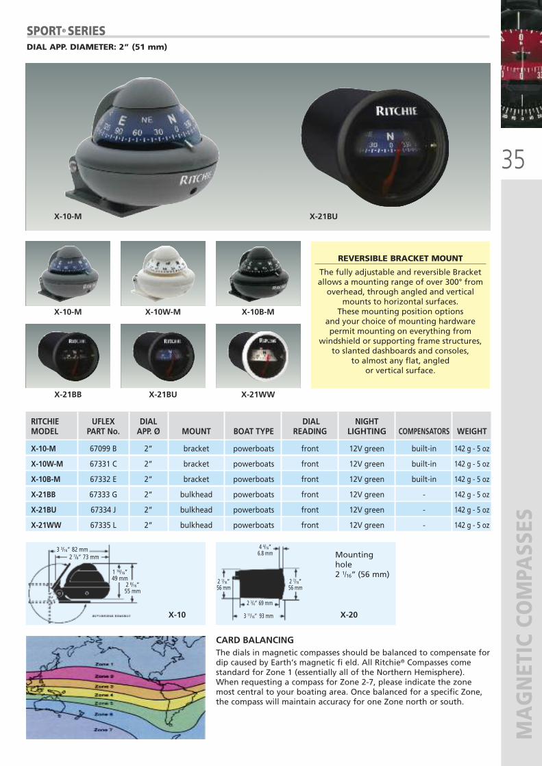
The dials in magnetic compasses should be balanced to compensate fordip caused by Earth’s magnetic fi eld. All Ritchie® Compasses comestandard for Zone 1 (essentially all of the Northern Hemisphere).When requesting a compass for Zone 2-7, please indicate the zonemost central to your boating area. Once balanced for a specific Zone,the compass will maintain accuracy for one Zone north or south.
CARD BALANCING
X-10 X-20
Mountinghole2 1/16” (56 mm)
3 3/16” 82 mm2 7/8” 73 mm
1 16/16”49 mm 2 1/16”
56 mm
4 4/16”6.8 mm
2 7/16”56 mm
2 3/4” 69 mm
3 11/16” 93 mm
2 8/16”55 mm
X-10-M
X-10-M X-10W-M X-10B-M
X-21BB X-21BU X-21WW
X-21BU
SPORT® SERIESDIAL APP. DIAMETER: 2” (51 mm)
RITCHIE UFLEX DIAL DIAL NIGHT MODEL PART No. APP. Ø MOUNT BOAT TYPE READING LIGHTING COMPENSATORS WEIGHT
X-10-M 67099 B 2” bracket powerboats front 12V green built-in 142 g - 5 oz
X-10W-M 67331 C 2” bracket powerboats front 12V green built-in 142 g - 5 oz
X-10B-M 67332 E 2” bracket powerboats front 12V green built-in 142 g - 5 oz
X-21BB 67333 G 2” bulkhead powerboats front 12V green - 142 g - 5 oz
X-21BU 67334 J 2” bulkhead powerboats front 12V green - 142 g - 5 oz
X-21WW 67335 L 2” bulkhead powerboats front 12V green - 142 g - 5 oz
REVERSIBLE BRACKET MOUNT
The fully adjustable and reversible Bracketallows a mounting range of over 300° fromoverhead, through angled and vertical
mounts to horizontal surfaces.These mounting position options
and your choice of mounting hardwarepermit mounting on everything from
windshield or supporting frame structures,to slanted dashboards and consoles,
to almost any flat, angledor vertical surface.
36
MAGNETIC COMPASSES
TR-35 TR-31 TR-33
1 9/18”60 mm
2 7/8”73 mm
2 3/8”60 mm
3” 76 mm3 1/2”90 mm1 9/18”
60 mm
13/16”21 mm
3” 76 mm3 11/16” 94 mm
TR-35G TR-31 TR-33W
TR-35 TR-31 TR-33
TR-35W TR-31W TR-33W
TR-35G TR-31G TR-33G
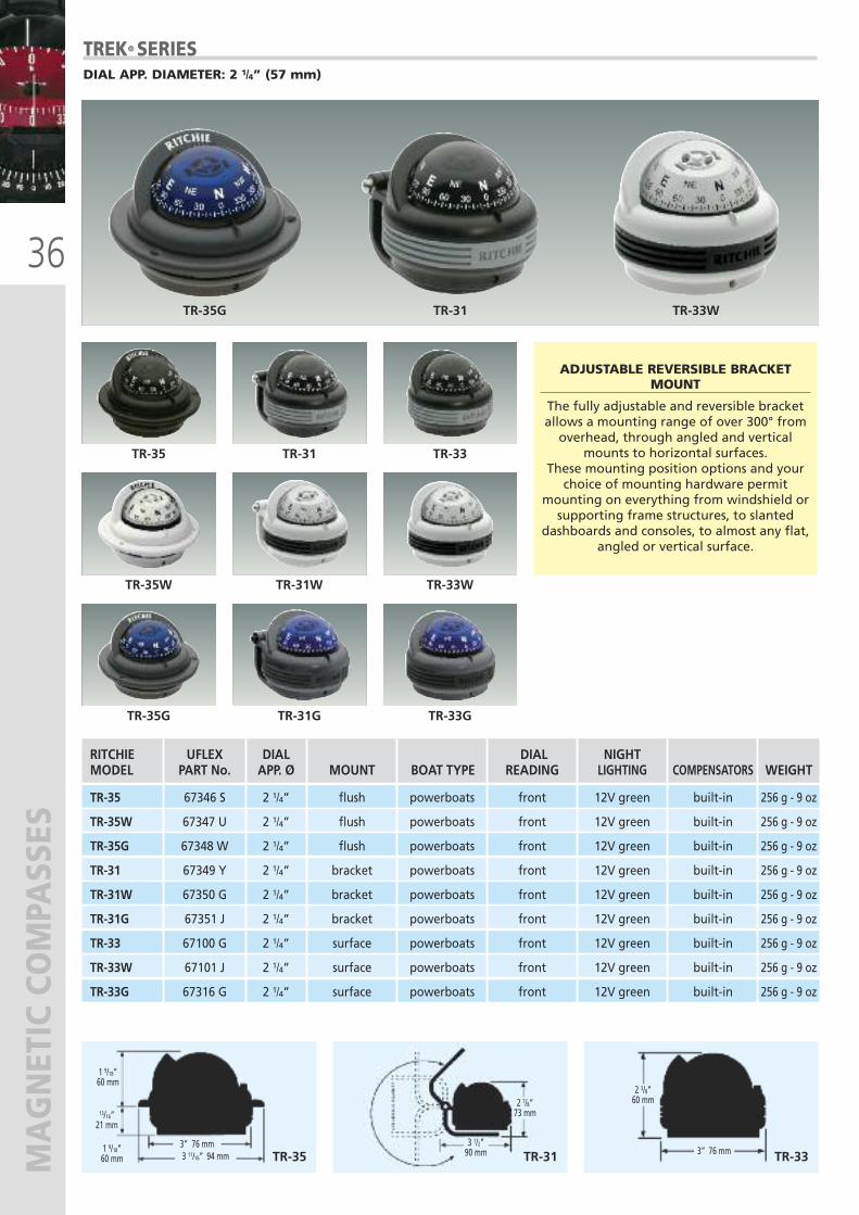
TREK® SERIESDIAL APP. DIAMETER: 2 1/4” (57 mm)
RITCHIE UFLEX DIAL DIAL NIGHT MODEL PART No. APP. Ø MOUNT BOAT TYPE READING LIGHTING COMPENSATORS WEIGHT
TR-35 67346 S 2 1/4” flush powerboats front 12V green built-in 256 g - 9 oz
TR-35W 67347 U 2 1/4” flush powerboats front 12V green built-in 256 g - 9 oz
TR-35G 67348 W 2 1/4” flush powerboats front 12V green built-in 256 g - 9 oz
TR-31 67349 Y 2 1/4” bracket powerboats front 12V green built-in 256 g - 9 oz
TR-31W 67350 G 2 1/4” bracket powerboats front 12V green built-in 256 g - 9 oz
TR-31G 67351 J 2 1/4” bracket powerboats front 12V green built-in 256 g - 9 oz
TR-33 67100 G 2 1/4” surface powerboats front 12V green built-in 256 g - 9 oz
TR-33W 67101 J 2 1/4” surface powerboats front 12V green built-in 256 g - 9 oz
TR-33G 67316 G 2 1/4” surface powerboats front 12V green built-in 256 g - 9 oz
ADJUSTABLE REVERSIBLE BRACKETMOUNT
The fully adjustable and reversible bracketallows a mounting range of over 300° fromoverhead, through angled and vertical
mounts to horizontal surfaces.These mounting position options and yourchoice of mounting hardware permit
mounting on everything from windshield orsupporting frame structures, to slanted
dashboards and consoles, to almost any flat,angled or vertical surface.
37
MAGNETIC COMPASSES
XP-99W
K-TD-2
RA-91
XP-99XP-99W
RA-93 S-OFF90
XP-99
4 9/18”116 mm
3 6/8”93 mm
2 7/8”73 mm
3 6/8”93 mm
2 7/8”73 mm
4 11/16”119 mm
4 ”102 mm
2 3/4”70 mm
4 1/4”104 mm
RA-91 RA-93 S-OFF90
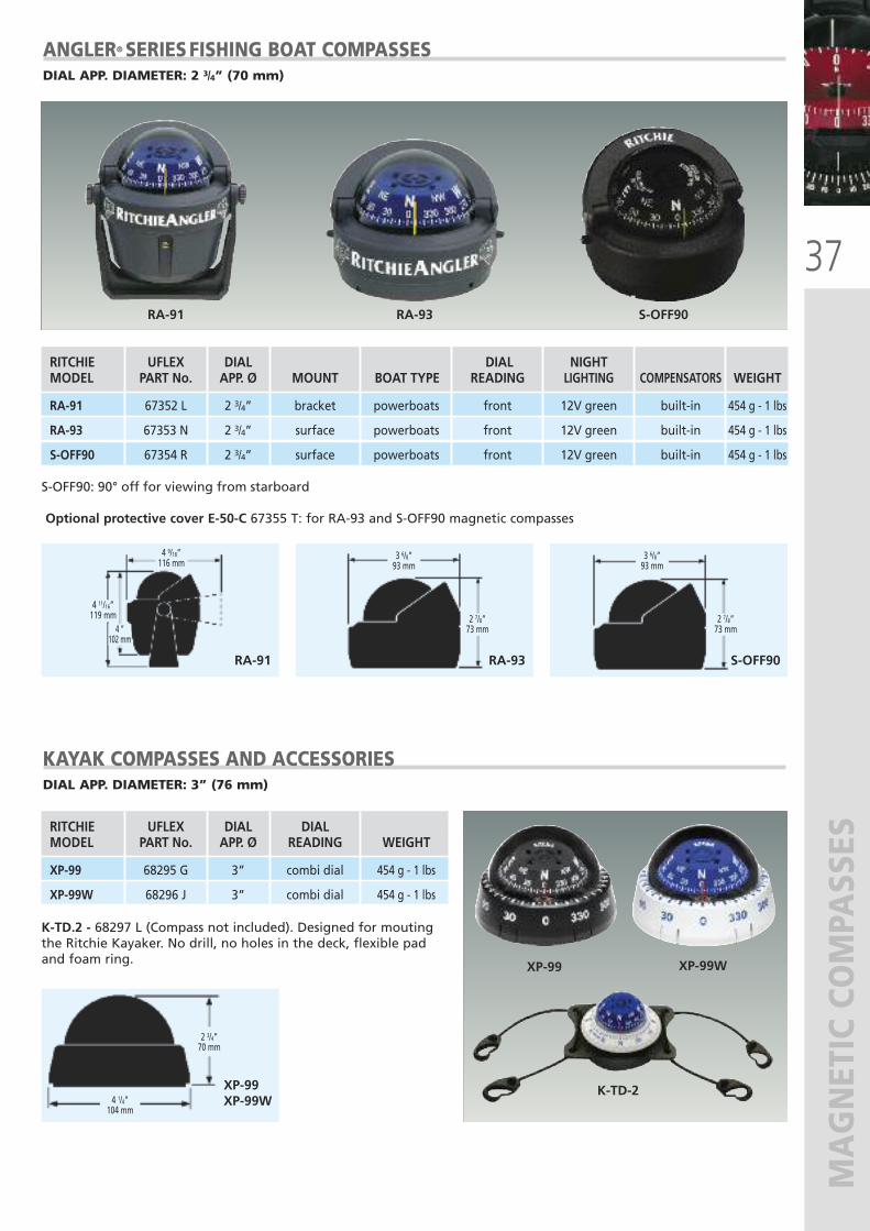
ANGLER® SERIESFISHING BOAT COMPASSESDIAL APP. DIAMETER: 2 3/4” (70 mm)
S-OFF90: 90° off for viewing from starboard
Optional protective cover E-50-C 67355 T: for RA-93 and S-OFF90 magnetic compasses
RITCHIE UFLEX DIAL DIAL NIGHT MODEL PART No. APP. Ø MOUNT BOAT TYPE READING LIGHTING COMPENSATORS WEIGHT
RA-91 67352 L 2 3/4” bracket powerboats front 12V green built-in 454 g - 1 lbs
RA-93 67353 N 2 3/4” surface powerboats front 12V green built-in 454 g - 1 lbs
S-OFF90 67354 R 2 3/4” surface powerboats front 12V green built-in 454 g - 1 lbs
KAYAK COMPASSES AND ACCESSORIESDIAL APP. DIAMETER: 3” (76 mm)
RITCHIE UFLEX DIAL DIAL MODEL PART No. APP. Ø READING WEIGHT
XP-99 68295 G 3” combi dial 454 g - 1 lbs
XP-99W 68296 J 3” combi dial 454 g - 1 lbs
K-TD.2 - 68297 L (Compass not included). Designed for moutingthe Ritchie Kayaker. No drill, no holes in the deck, flexible padand foam ring.
38
MAGNETIC COMPASSES
F-50 S-53G V-537B
B-51W V-57W.2 D-55
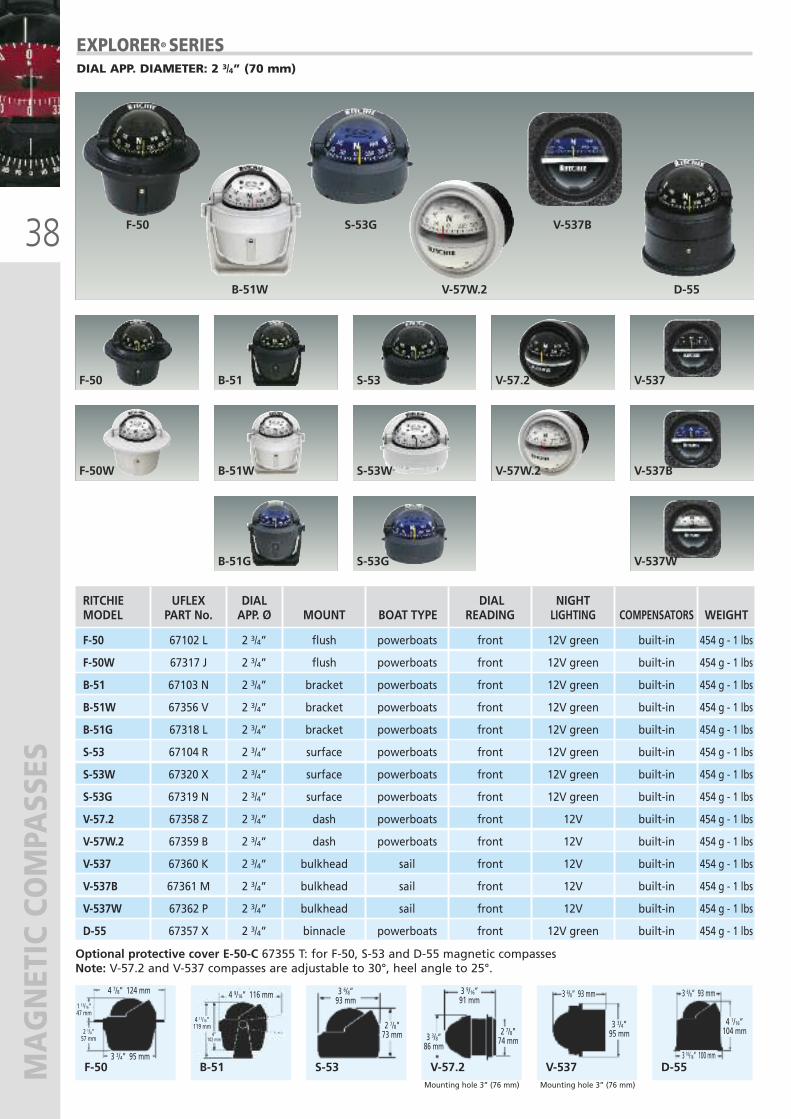
EXPLORER® SERIESDIAL APP. DIAMETER: 2 3/4” (70 mm)
F-50
F-50W
B-51
B-51W
B-51G
S-53
S-53W
S-53G
V-537
V-537B
V-537W
V-57.2
V-57W.2
Optional protective cover E-50-C 67355 T: for F-50, S-53 and D-55 magnetic compassesNote: V-57.2 and V-537 compasses are adjustable to 30°, heel angle to 25°.
RITCHIE UFLEX DIAL DIAL NIGHT MODEL PART No. APP. Ø MOUNT BOAT TYPE READING LIGHTING COMPENSATORS WEIGHT
F-50 67102 L 2 3/4” flush powerboats front 12V green built-in 454 g - 1 lbs
F-50W 67317 J 2 3/4” flush powerboats front 12V green built-in 454 g - 1 lbs
B-51 67103 N 2 3/4” bracket powerboats front 12V green built-in 454 g - 1 lbs
B-51W 67356 V 2 3/4” bracket powerboats front 12V green built-in 454 g - 1 lbs
B-51G 67318 L 2 3/4” bracket powerboats front 12V green built-in 454 g - 1 lbs
S-53 67104 R 2 3/4” surface powerboats front 12V green built-in 454 g - 1 lbs
S-53W 67320 X 2 3/4” surface powerboats front 12V green built-in 454 g - 1 lbs
S-53G 67319 N 2 3/4” surface powerboats front 12V green built-in 454 g - 1 lbs
V-57.2 67358 Z 2 3/4” dash powerboats front 12V built-in 454 g - 1 lbs
V-57W.2 67359 B 2 3/4” dash powerboats front 12V built-in 454 g - 1 lbs
V-537 67360 K 2 3/4” bulkhead sail front 12V built-in 454 g - 1 lbs
V-537B 67361 M 2 3/4” bulkhead sail front 12V built-in 454 g - 1 lbs
V-537W 67362 P 2 3/4” bulkhead sail front 12V built-in 454 g - 1 lbs
D-55 67357 X 2 3/4” binnacle powerboats front 12V green built-in 454 g - 1 lbs
F-50 B-51 S-53 V-57.2 V-537 D-55Mounting hole 3” (76 mm) Mounting hole 3” (76 mm)
4 7/8” 124 mm 4 9/16” 116 mm
3 3/4” 95 mm
1 13/16”47 mm
4 11/16”119 mm
4”102 mm
2 1/4”57 mm
3 6/8”93 mm
2 7/8”73 mm 2 7/8”
74 mm3 3/8”86 mm
3 9/16”91 mm
3 6/8” 93 mm3 6/8” 93 mm
3 16/16” 100 mm
4 1/16”104 mm
3 3/4”95 mm
39
MAGNETIC COMPASSES
D-84
F-83 S-87W
F-82W B-81
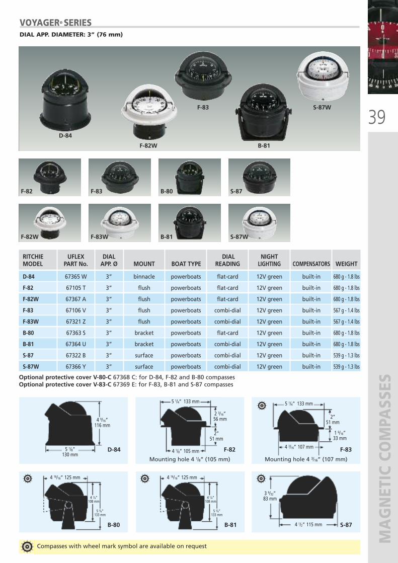
VOYAGER® SERIESDIAL APP. DIAMETER: 3” (76 mm)
F-82
F-82W
F-83
F-83W
B-80
B-81
S-87
S-87W
Optional protective cover V-80-C 67368 C: for D-84, F-82 and B-80 compassesOptional protective cover V-83-C 67369 E: for F-83, B-81 and S-87 compasses
RITCHIE UFLEX DIAL DIAL NIGHT MODEL PART No. APP. Ø MOUNT BOAT TYPE READING LIGHTING COMPENSATORS WEIGHT
D-84 67365 W 3” binnacle powerboats flat-card 12V green built-in 680 g - 1.8 lbs
F-82 67105 T 3” flush powerboats flat-card 12V green built-in 680 g - 1.8 lbs
F-82W 67367 A 3” flush powerboats flat-card 12V green built-in 680 g - 1.8 lbs
F-83 67106 V 3” flush powerboats combi-dial 12V green built-in 567 g - 1.4 lbs
F-83W 67321 Z 3” flush powerboats combi-dial 12V green built-in 567 g - 1.4 lbs
B-80 67363 S 3” bracket powerboats flat-card 12V green built-in 680 g - 1.8 lbs
B-81 67364 U 3” bracket powerboats combi-dial 12V green built-in 680 g - 1.8 lbs
S-87 67322 B 3” surface powerboats combi-dial 12V green built-in 539 g - 1.3 lbs
S-87W 67366 Y 3” surface powerboats combi-dial 12V green built-in 539 g - 1.3 lbs
D-84 F-82 F-83
B-80 S-87
Mounting hole 4 1/8” (105 mm) Mounting hole 4 3/16” (107 mm)
B-81
Compasses with wheel mark symbol are available on request
4 9/16”116 mm
2 3/16”56 mm
4 1/4”108 mm
5 2/4”133 mm
2”51 mm
2”51 mm
1 6/16”33 mm
4 1/8” 105 mm
4 16/16” 125 mm
4 1/4”108 mm
5 2/4”133 mm
4 16/16” 125 mm
4 1/2” 115 mm
3 9/32”83 mm
4 3/16” 107 mm
5 1/4” 133 mm 5 1/4” 133 mm
5 1/8”130 mm
40
MAGNETIC COMPASSES
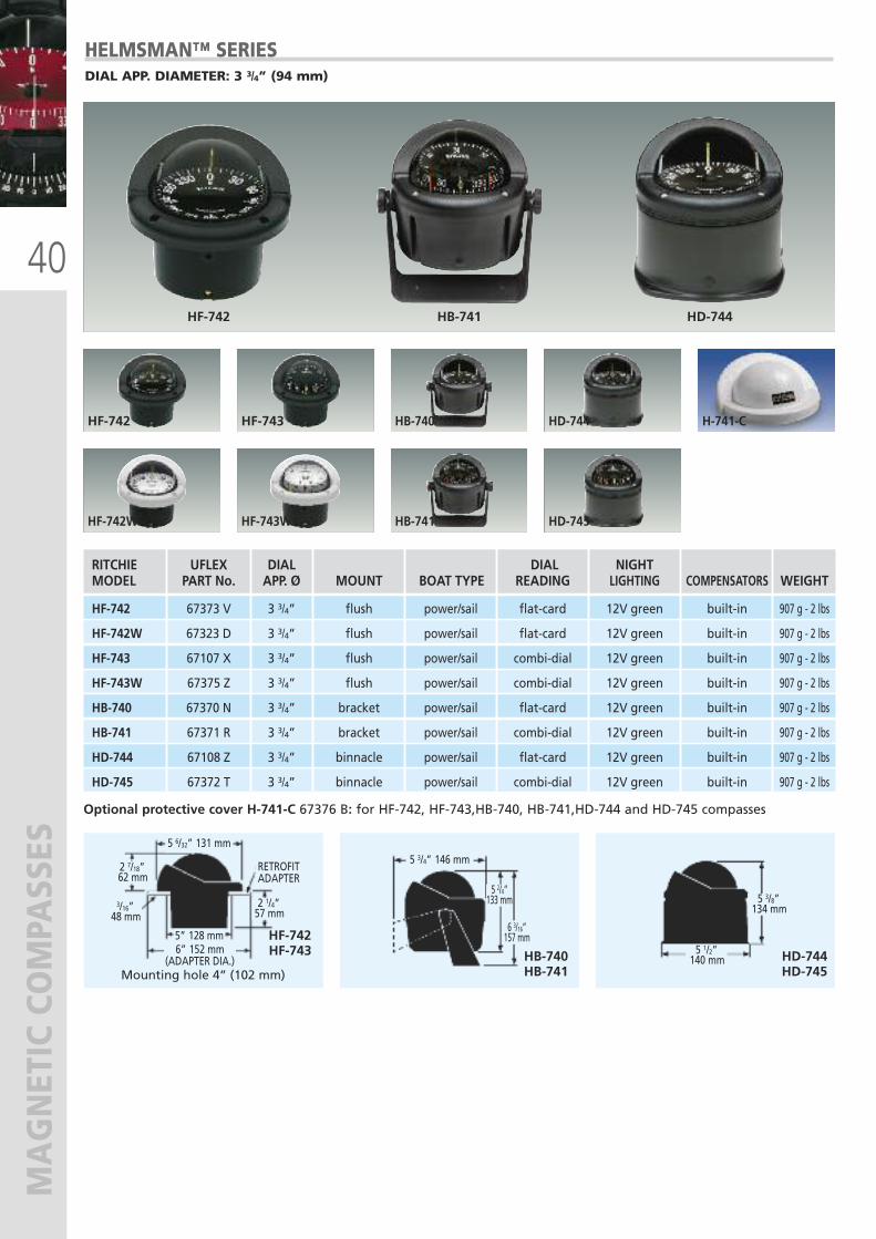
HELMSMAN™ SERIESDIAL APP. DIAMETER: 3 3/4” (94 mm)
HF-742
HF-742W
HF-743
HF-743W
HB-740
HB-741
HD-744
HD-745
Optional protective cover H-741-C 67376 B: for HF-742, HF-743,HB-740, HB-741,HD-744 and HD-745 compasses
HF-742 HB-741 HD-744
RITCHIE UFLEX DIAL DIAL NIGHT MODEL PART No. APP. Ø MOUNT BOAT TYPE READING LIGHTING COMPENSATORS WEIGHT
HF-742 67373 V 3 3/4” flush power/sail flat-card 12V green built-in 907 g - 2 lbs
HF-742W 67323 D 3 3/4” flush power/sail flat-card 12V green built-in 907 g - 2 lbs
HF-743 67107 X 3 3/4” flush power/sail combi-dial 12V green built-in 907 g - 2 lbs
HF-743W 67375 Z 3 3/4” flush power/sail combi-dial 12V green built-in 907 g - 2 lbs
HB-740 67370 N 3 3/4” bracket power/sail flat-card 12V green built-in 907 g - 2 lbs
HB-741 67371 R 3 3/4” bracket power/sail combi-dial 12V green built-in 907 g - 2 lbs
HD-744 67108 Z 3 3/4” binnacle power/sail flat-card 12V green built-in 907 g - 2 lbs
HD-745 67372 T 3 3/4” binnacle power/sail combi-dial 12V green built-in 907 g - 2 lbs
H-741-C
HF-743
HB-741
HF-742
HB-740HD-745HD-744
Mounting hole 4” (102 mm)
5 6/32” 131 mm5 3/4” 146 mm
2 1/4”57 mm
5 3/8”134 mm
5 1/2”140 mm
5 2/4”133 mm
6 3/16”157 mm
2 7/18”62 mm
3/16”48 mm
6” 152 mm(ADAPTER DIA.)
RETROFITADAPTER
5” 128 mm
41
MAGNETIC COMPASSES5 6/32” 131 mm
2 1/4”57 mm
2 7/18”62 mm
3/16”48 mm
6” 152 mm(ADAPTER DIA.)
RETROFITADAPTER
4” 102 mm
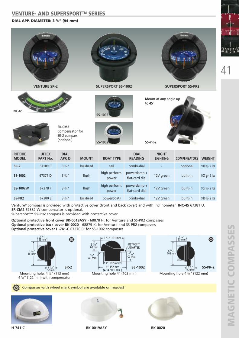
VENTURE® AND SUPERSPORT™ SERIESDIAL APP. DIAMETER: 3 3/4” (94 mm)
SS-1002
SS-1002W SS-PR-2
Venture® compass is provided with protective cover (front and back cover) and with inclinometer INC-45 67381 U. SR-CM2 67382 W compensator is optional.Supersport™ SS-PR2 compass is provided with protective cover.
Optional protective front cover BK-0019ASY - 68878 H: for Venture and SS-PR2 compassesOptional protective back cover BK-0020 - 68879 K: for Venture and SS-PR2 compassesOptional protective cover H-741-C 67376 B: for SS-1002 compasses
SR-2 SS-1002 SS-PR-2
Mount at any angle upto 45°
SR-CM2Compensator forSR-2 compass (optional)
VENTURE SR-2 SUPERSPORT SS-1002 SUPERSPORT SS-PR2
INC-45
Mounting hole: 4 1/2” (113 mm)4 5/8” (122 mm) with compensator
Mounting hole 4” (102 mm) Mounting hole 4 5/8” (122 mm)
2 1/2”63 mm
6 7/16”163 mm
2 1/32”52 mm
2 1/4”63 mm
2 1/32”52 mm
6 7/18”163 mm
Compasses with wheel mark symbol are available on request
H-741-C BK-0019ASY BK-0020
RITCHIE UFLEX DIAL DIAL NIGHT MODEL PART No. APP. Ø MOUNT BOAT TYPE READING LIGHTING COMPENSATORS WEIGHT
SR-2 67109 B 3 3/4” bulkhead sail combi-dial - optional 910 g - 2 lbs
high perform. powerdamp + SS-1002 67377 D 3 3/4” flush
power flat-card dial 12V green built-in 907 g - 2 lbs
high perform. powerdamp + SS-1002W 67378 F 3 3/4” flush
power flat-card dial 12V green built-in 907 g - 2 lbs
SS-PR2 67380 S 3 3/4” bulkhead powerboats combi-dial 12V green built-in 910 g - 2 lbs
42
MAGNETIC COMPASSES
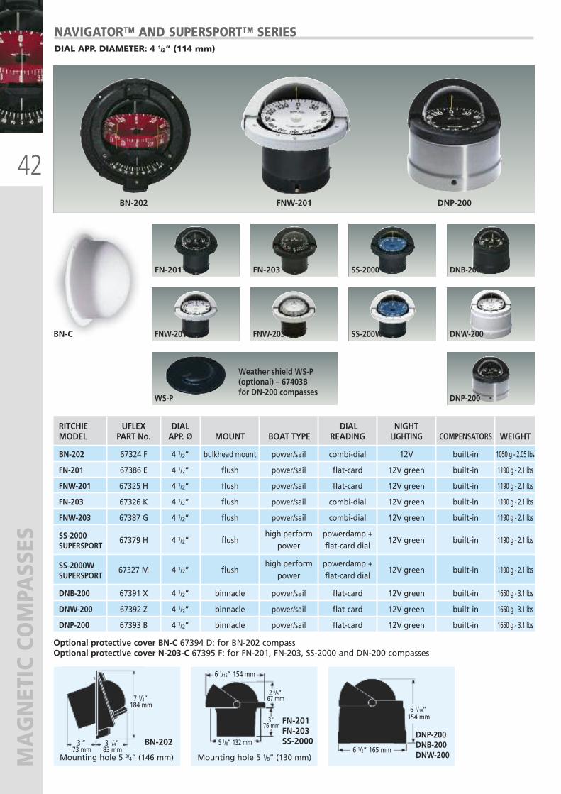
NAVIGATOR™ AND SUPERSPORT™ SERIESDIAL APP. DIAMETER: 4 1/2” (114 mm)
RITCHIE UFLEX DIAL DIAL NIGHT MODEL PART No. APP. Ø MOUNT BOAT TYPE READING LIGHTING COMPENSATORS WEIGHT
BN-202 67324 F 4 1/2” bulkhead mount power/sail combi-dial 12V built-in 1050 g - 2.05 lbs
FN-201 67386 E 4 1/2” flush power/sail flat-card 12V green built-in 1190 g - 2.1 lbs
FNW-201 67325 H 4 1/2” flush power/sail flat-card 12V green built-in 1190 g - 2.1 lbs
FN-203 67326 K 4 1/2” flush power/sail combi-dial 12V green built-in 1190 g - 2.1 lbs
FNW-203 67387 G 4 1/2” flush power/sail combi-dial 12V green built-in 1190 g - 2.1 lbs
SS-2000 high perform powerdamp + SUPERSPORT
67379 H 4 1/2” flush power flat-card dial
12V green built-in 1190 g - 2.1 lbs
SS-2000W high perform powerdamp + SUPERSPORT
67327 M 4 1/2” flush power flat-card dial
12V green built-in 1190 g - 2.1 lbs
DNB-200 67391 X 4 1/2” binnacle power/sail flat-card 12V green built-in 1650 g - 3.1 lbs
DNW-200 67392 Z 4 1/2” binnacle power/sail flat-card 12V green built-in 1650 g - 3.1 lbs
DNP-200 67393 B 4 1/2” binnacle power/sail flat-card 12V green built-in 1650 g - 3.1 lbs
FN-201
FNW-201
FN-203
FNW-203
SS-2000
SS-200W
DNB-200
DNW-200
DNP-200WS-P
Weather shield WS-P (optional) – 67403B for DN-200 compasses
Optional protective cover BN-C 67394 D: for BN-202 compassOptional protective cover N-203-C 67395 F: for FN-201, FN-203, SS-2000 and DN-200 compasses
BN-202
FN-201FN-203SS-2000
DNP-200DNB-200DNW-200
BN-202 FNW-201 DNP-200
Mounting hole 5 1/8” (130 mm)Mounting hole 5 3/4” (146 mm)
BN-C
7 1/4”184 mm
3 1/4”83 mm
3 ”73 mm
6 1/16” 154 mm
5 1/8” 132 mm
2 6/8”67 mm
3”76 mm
6 1/16”154 mm
6 1/2” 165 mm
43
MAGNETIC COMPASSES
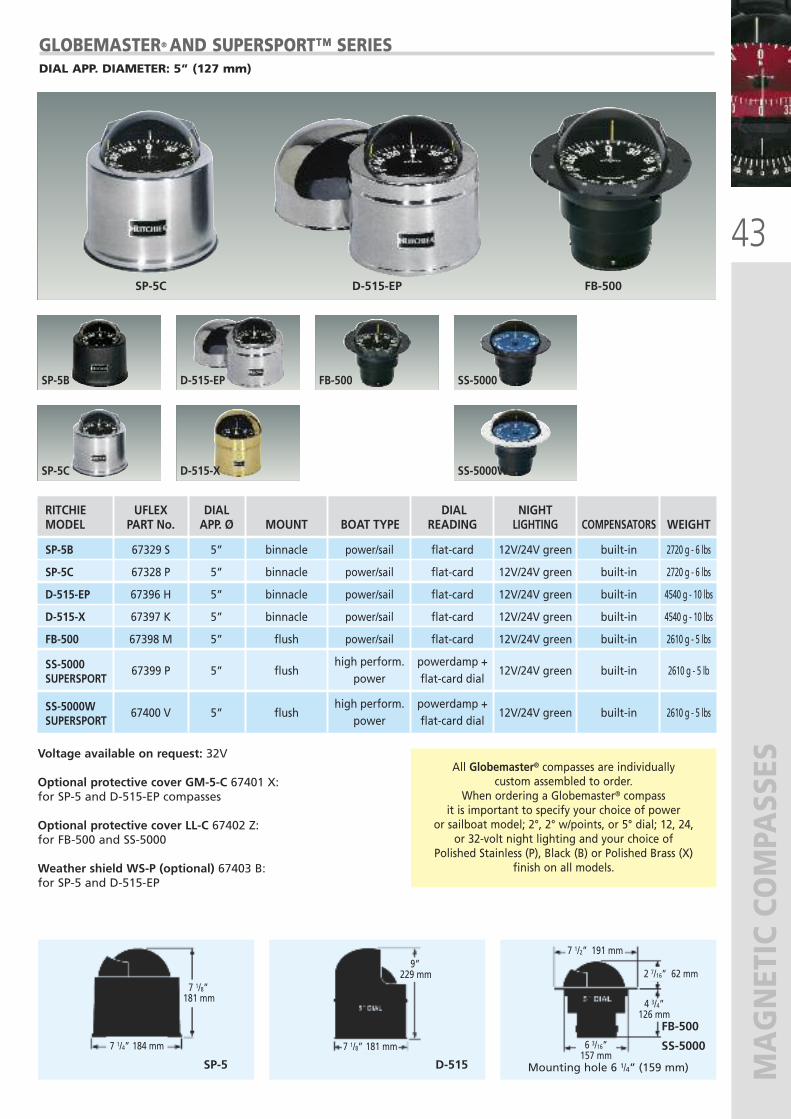
Voltage available on request: 32V
Optional protective cover GM-5-C 67401 X: for SP-5 and D-515-EP compasses
Optional protective cover LL-C 67402 Z: for FB-500 and SS-5000
Weather shield WS-P (optional) 67403 B: for SP-5 and D-515-EP
SP-5B
SP-5C
D-515-EP
D-515-X
SP-5C D-515-EP FB-500
RITCHIE UFLEX DIAL DIAL NIGHT MODEL PART No. APP. Ø MOUNT BOAT TYPE READING LIGHTING COMPENSATORS WEIGHT
SP-5B 67329 S 5” binnacle power/sail flat-card 12V/24V green built-in 2720 g - 6 lbs
SP-5C 67328 P 5” binnacle power/sail flat-card 12V/24V green built-in 2720 g - 6 lbs
D-515-EP 67396 H 5” binnacle power/sail flat-card 12V/24V green built-in 4540 g - 10 lbs
D-515-X 67397 K 5” binnacle power/sail flat-card 12V/24V green built-in 4540 g - 10 lbs
FB-500 67398 M 5” flush power/sail flat-card 12V/24V green built-in 2610 g - 5 lbs
SS-5000 high perform. powerdamp + SUPERSPORT
67399 P 5” flush power flat-card dial
12V/24V green built-in 2610 g - 5 lb
SS-5000W high perform. powerdamp + SUPERSPORT
67400 V 5” flush power flat-card dial
12V/24V green built-in 2610 g - 5 lbs
SP-5 D-515
SS-5000
FB-500
Mounting hole 6 1/4” (159 mm)
GLOBEMASTER® AND SUPERSPORT™ SERIESDIAL APP. DIAMETER: 5” (127 mm)
FB-500
SS-5000W
SS-5000
All Globemaster® compasses are individually custom assembled to order.
When ordering a Globemaster® compass it is important to specify your choice of power
or sailboat model; 2°, 2° w/points, or 5° dial; 12, 24, or 32-volt night lighting and your choice of
Polished Stainless (P), Black (B) or Polished Brass (X) finish on all models.
7 1/8”181 mm
7 1/4” 184 mm 7 1/8” 181 mm
9”229 mm
7 1/2” 191 mm
6 3/16”157 mm
4 3/4”126 mm
2 7/16” 62 mm
44
MAGNETIC COMPASSES
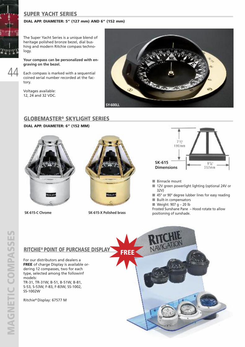
SY-600LL
SUPER YACHT SERIESDIAL APP. DIAMETER: 5” (127 mm) AND 6” (152 mm)
The Super Yacht Series is a unique blend ofheritage polished bronze bezel, dial bus-hing and modern Ritchie compass techno-logy.
Your compass can be personalized with en-graving on the bezel.
Each compass is marked with a sequentialcoined serial number recorded at the fac-tory.
Voltages available: 12, 24 and 32 VDC.
For our distributors and dealers aFREE of charge Display is available or-dering 12 compasses, two for eachtype, selected among the followinfmodels:TR-31, TR-31W, B-51, B-51W, B-81, S-53, S-53W, F-83, F-83W, SS-1002, SS-1002W
Ritchie® Display: 67577 M
� Binnacle mount� 12V green powerlight lighting (optional 24V or32V)
� 45° or 90° degree lubber lines for easy reading� Built-in compensators� Weight: 907 g – 20 lbFrosted Sunshane Pane – Hood rotate to allowpositioning of sunshade.SK-615-C Chrome SK-615-X Polished brass
GLOBEMASTER® SKYLIGHT SERIES
RITCHIE® POINT OF PURCHASE DISPLAY
DIAL APP. DIAMETER: 6” (152 MM)
SK-615Dimensions
FREE
45
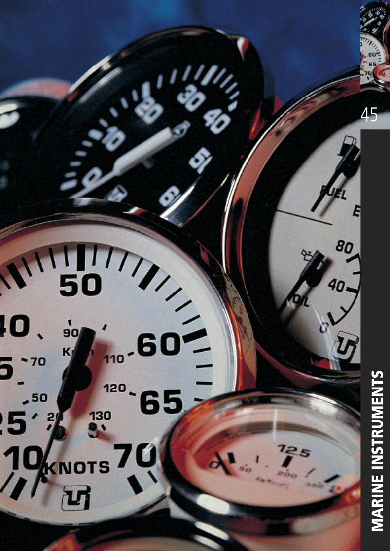
MARINE INSTRUMENTS
46
INSTRUMENTS - ULTRA
AND ULTRA
WHITE SERIES
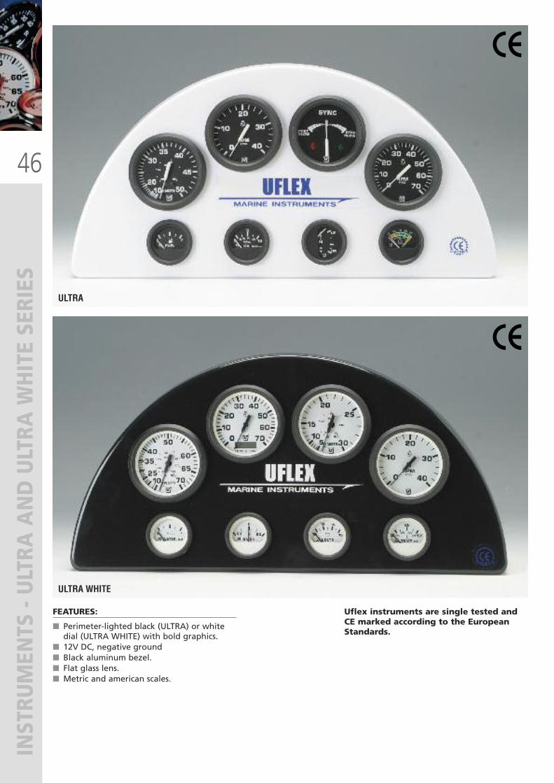
ULTRA
ULTRA WHITE
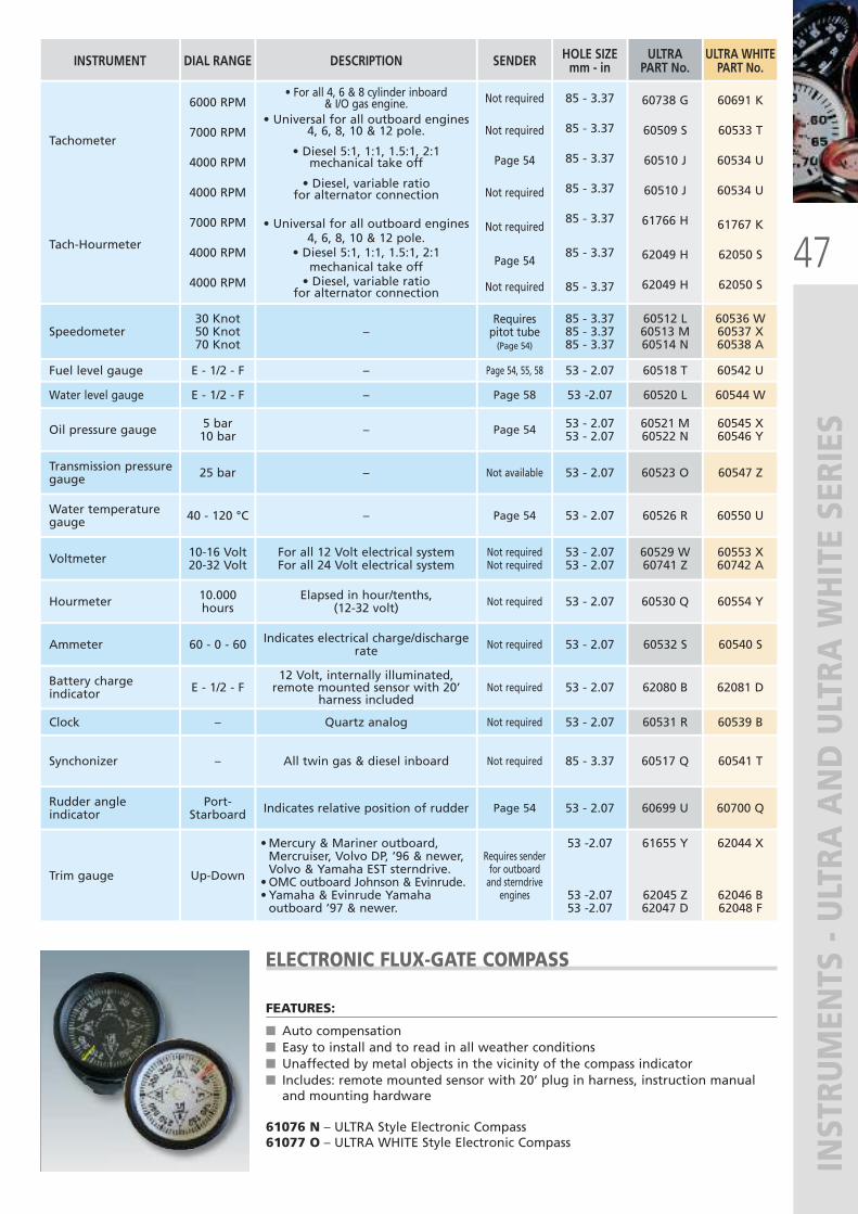
FEATURES:
� Perimeter-lighted black (ULTRA) or whitedial (ULTRA WHITE) with bold graphics.
� 12V DC, negative ground� Black aluminum bezel.� Flat glass lens.� Metric and american scales.
Uflex instruments are single tested andCE marked according to the EuropeanStandards.
47
INSTRUMENTS - ULTRA
AND ULTRA
WHITE SERIES
ELECTRONIC FLUX-GATE COMPASS
FEATURES:
� Auto compensation� Easy to install and to read in all weather conditions� Unaffected by metal objects in the vicinity of the compass indicator� Includes: remote mounted sensor with 20’ plug in harness, instruction manualand mounting hardware
61076 N – ULTRA Style Electronic Compass61077 O – ULTRA WHITE Style Electronic Compass
INSTRUMENT DIAL RANGE DESCRIPTION SENDER ULTRAPART No.
ULTRA WHITEPART No.
Tachometer
Tach-Hourmeter
6000 RPM
7000 RPM
4000 RPM
4000 RPM
7000 RPM
4000 RPM
4000 RPM
• For all 4, 6 & 8 cylinder inboard & I/O gas engine.
• Universal for all outboard engines4, 6, 8, 10 & 12 pole.
• Diesel 5:1, 1:1, 1.5:1, 2:1mechanical take off
• Diesel, variable ratiofor alternator connection
• Universal for all outboard engines4, 6, 8, 10 & 12 pole.
• Diesel 5:1, 1:1, 1.5:1, 2:1mechanical take off• Diesel, variable ratio
for alternator connection
Not required
Not required
Page 54
Not required
Not required
Page 54
Not required
60738 G
60509 S
60510 J
60510 J
61766 H
62049 H
62049 H
60691 K
60533 T
60534 U
60534 U
61767 K
62050 S
62050 S
Speedometer30 Knot50 Knot70 Knot
–Requirespitot tube(Page 54)
60512 L60513 M60514 N
60536 W60537 X60538 A
Fuel level gauge E - 1/2 - F – Page 54, 55, 58 60518 T 60542 U
Water level gauge E - 1/2 - F – Page 58 60520 L 60544 W
Oil pressure gauge 5 bar10 bar – Page 54 60521 M
60522 N60545 X60546 Y
Transmission pressuregauge 25 bar – Not available 60523 O 60547 Z
Water temperaturegauge 40 - 120 °C – Page 54 60526 R 60550 U
Voltmeter 10-16 Volt20-32 Volt
For all 12 Volt electrical systemFor all 24 Volt electrical system
Not requiredNot required
60529 W60741 Z
60553 X60742 A
Hourmeter 10.000hours
Elapsed in hour/tenths, (12-32 volt) Not required 60530 Q 60554 Y
Ammeter 60 - 0 - 60 Indicates electrical charge/dischargerate Not required 60532 S 60540 S
Battery chargeindicator E - 1/2 - F
12 Volt, internally illuminated,remote mounted sensor with 20’
harness includedNot required 62080 B 62081 D
Clock – Quartz analog Not required 60531 R 60539 B
Synchonizer – All twin gas & diesel inboard Not required 60517 Q 60541 T
Rudder angleindicator
Port-Starboard Indicates relative position of rudder Page 54 60699 U 60700 Q
Trim gauge Up-Down
•Mercury & Mariner outboard,Mercruiser, Volvo DP, ’96 & newer,Volvo & Yamaha EST sterndrive.•OMC outboard Johnson & Evinrude. • Yamaha & Evinrude Yamahaoutboard ’97 & newer.
Requires senderfor outboardand sterndrive
engines
61655 Y
62045 Z62047 D
62044 X
62046 B62048 F
HOLE SIZEmm - in
85 - 3.37
85 - 3.37
85 - 3.37
85 - 3.37
85 - 3.37
85 - 3.37
85 - 3.37
85 - 3.3785 - 3.3785 - 3.37
53 - 2.07
53 -2.07
53 - 2.0753 - 2.07
53 - 2.07
53 - 2.07
53 - 2.0753 - 2.07
53 - 2.07
53 - 2.07
53 - 2.07
53 - 2.07
85 - 3.37
53 - 2.07
53 -2.07
53 -2.0753 -2.07
48
INSTRUMENTS - BEIGE GOLD AND ULTRAWHITE SS SERIES
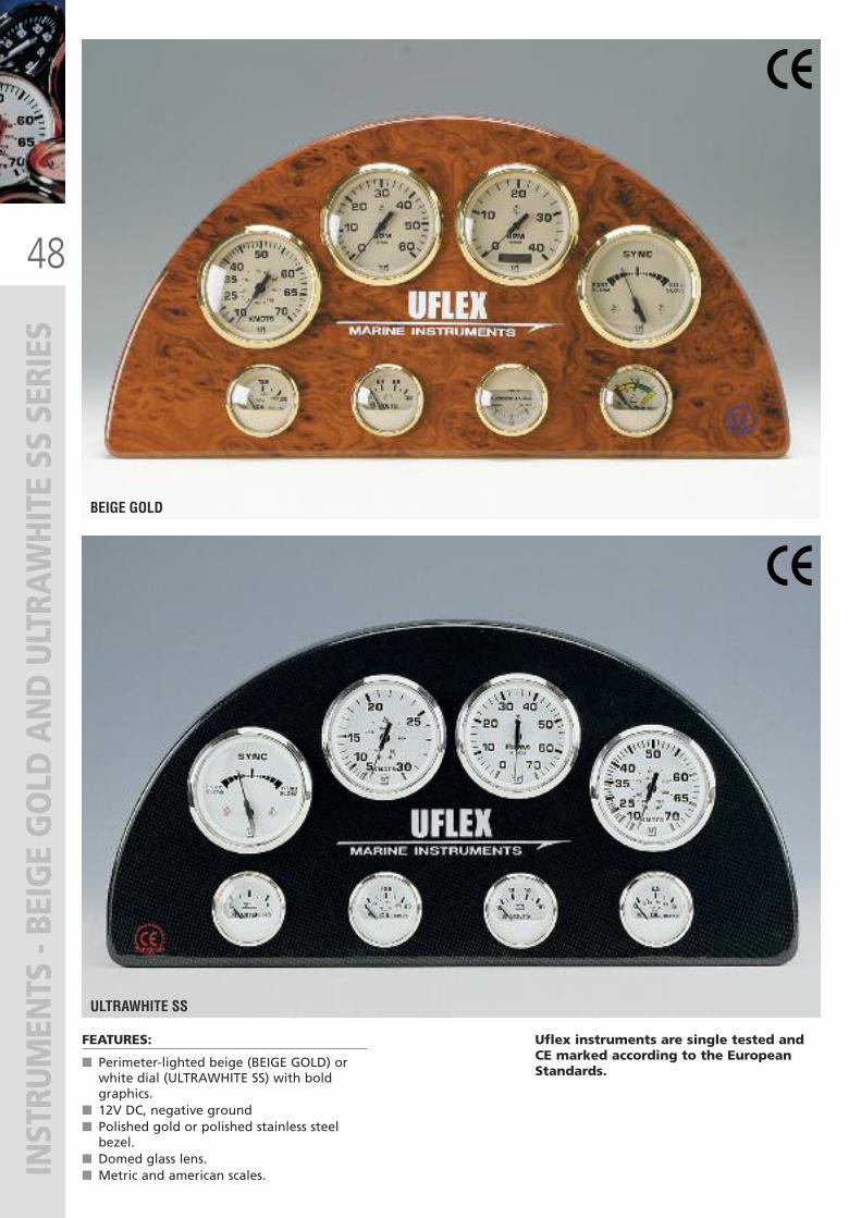
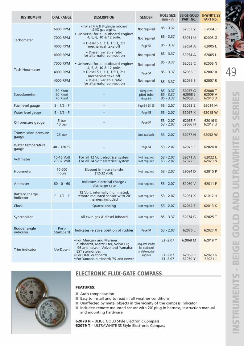
FEATURES:
� Perimeter-lighted beige (BEIGE GOLD) orwhite dial (ULTRAWHITE SS) with boldgraphics.
� 12V DC, negative ground� Polished gold or polished stainless steelbezel.
� Domed glass lens.� Metric and american scales.
BEIGE GOLD
ULTRAWHITE SS
Uflex instruments are single tested andCE marked according to the EuropeanStandards.
49
INSTRUMENTS - BEIGE GOLD AND ULTRAWHITE SS SERIES
ELECTRONIC FLUX-GATE COMPASS
FEATURES:
� Auto compensation� Easy to install and to read in all weather conditions� Unaffected by metal objects in the vicinity of the compass indicator� Includes: remote mounted sensor with 20’ plug in harness, instruction manualand mounting hardware
62078 R – BEIGE GOLD Style Electronic Compass62079 T – ULTRAWHITE SS Style Electronic Compass
INSTRUMENT DIAL RANGE DESCRIPTION SENDER BEIGE-GOLDPART No.
U-WHITE SSPART No.
Tachometer
Tach-Hourmeter
6000 RPM
7000 RPM
4000 RPM
4000 RPM
7000 RPM
4000 RPM
4000 RPM
• For all 4, 6 & 8 cylinder inboard & I/O gas engine.
• Universal for all outboard engines4, 6, 8, 10 & 12 pole.
• Diesel 5:1, 1:1, 1.5:1, 2:1mechanical take off
• Diesel, variable ratiofor alternator connection
• Universal for all outboard engines4, 6, 8, 10 & 12 pole.
• Diesel 5:1, 1:1, 1.5:1, 2:1mechanical take off• Diesel, variable ratio
for alternator connection
Not required
Not required
Page 54
Not required
Not required
Page 54
Not required
62053 Y
62051 U
62054 A
62054 A
62055 C
62056 E
62056 E
62004 J
62003 G
62005 L
62005 L
62006 N
62007 R
62007 R
Speedometer30 Knot50 Knot70 Knot
–Requirespitot tube(Page 54)
62057 G62058 J62059 L
62008 T62009 V62010 D
Fuel level gauge E - 1/2 - F – Page 54, 55, 58 62063 B 62014 M
Water level gauge E - 1/2 - F – Page 58 62067 K 62018 W
Oil pressure gauge 5 bar10 bar – Page 54 62065 F
62066 H62016 S62017 U
Transmission pressuregauge 25 bar – Not available 62077 N 62052 W
Water temperaturegauge 40 - 120 °C – Page 54 62073 E 62024 R
Voltmeter 10-16 Volt20-32 Volt
For all 12 Volt electrical systemFor all 24 Volt electrical system
Not requiredNot required
62071 A62072 C
62022 L62023 N
Hourmeter 10.000hours
Elapsed in hour / tenths (12-32 volt) Not required 62064 D 62015 P
Ammeter 60 - 0 - 60 Indicates electrical charge /discharge rate Not required 62060 V 62011 F
Battery chargeindicator E - 1/2 - F
12 Volt, internally illuminated,remote mounted sensor with 20’
harness includedNot required 62061 X 61012 H
Clock – Quartz analog Not required 62062 Z 62013 K
Syncronizer – All twin gas & diesel inboard Not required 62074 G 62025 T
Rudder angleindicator
Port-Starboard Indicates relative position of rudder Page 54 62076 L 62027 X
Trim indicator Up-Down
• For Mercury and Marineroutboards, Mercruiser, Volvo DP,’96 and newer, Volvo and YamahaEST sterndrives• For OMC outboards• For Yamaha outboards ’97 and newer
Requires senderfor outboardand sterndrive
engines
62068 M
62069 P62070 Y
62019 Y
62020 G62021 J
HOLE SIZEmm - in
85 - 3.37
85 - 3.37
85 - 3.37
85 - 3.37
85 - 3.37
85 - 3.37
85 - 3.37
85 - 3.3785 - 3.3785 - 3.37
53 - 2.07
53 - 2.07
53 - 2.0753 - 2.07
53 - 2.07
53 - 2.07
53 - 2.0753 - 2.07
53 - 2.07
53 - 2.07
53 - 2.07
53 - 2.07
85 - 3.37
53 - 2.07
53 -2.07
53 -2.0753 -2.07
50
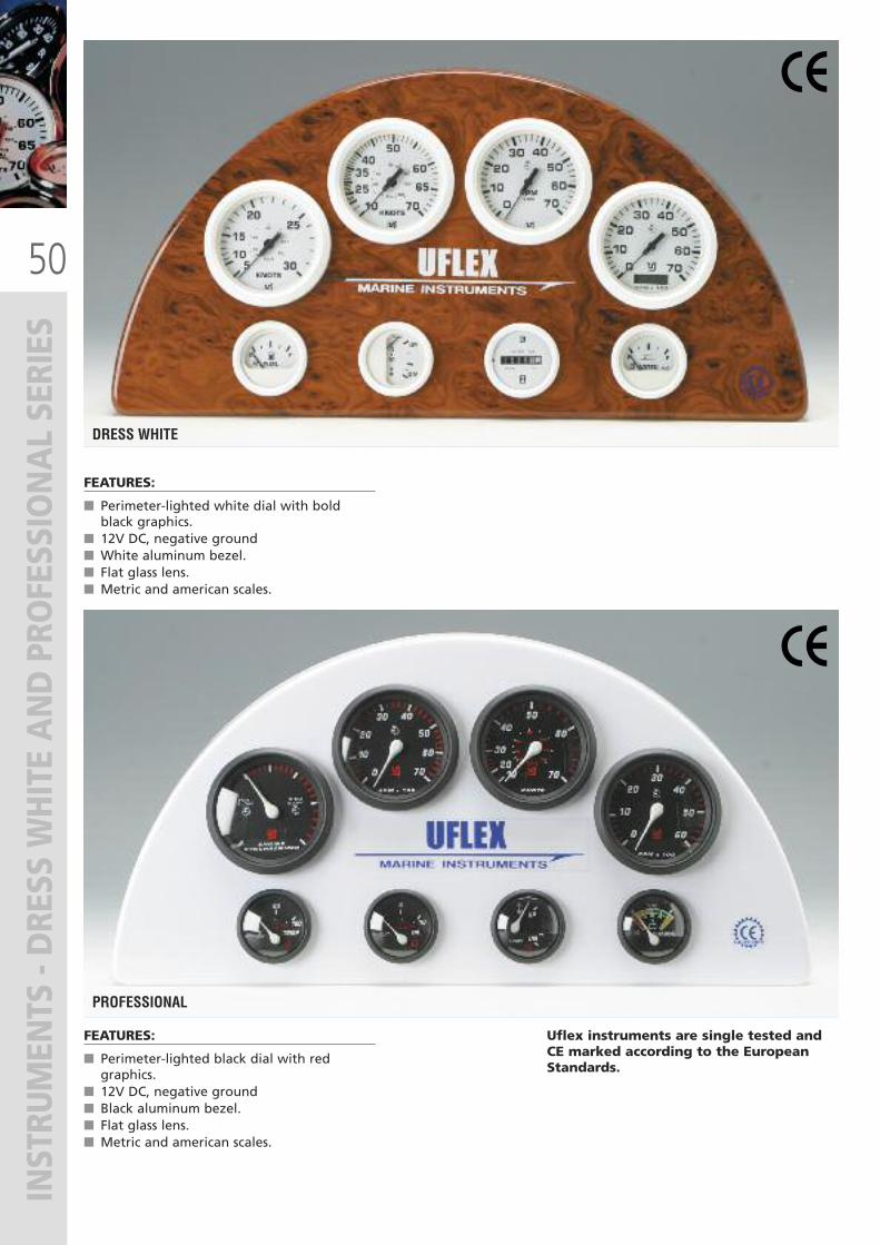
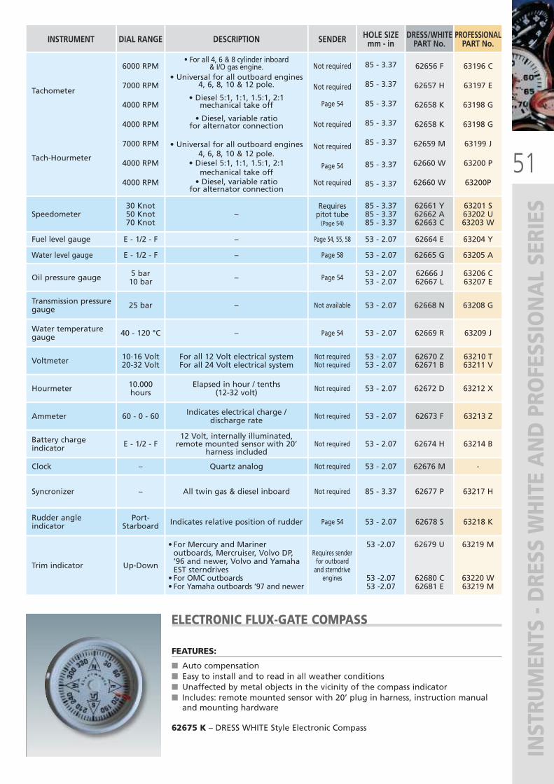
INSTRUMENTS - DRESS WHITE AND PROFESSIONAL SERIES
FEATURES:
� Perimeter-lighted white dial with boldblack graphics.
� 12V DC, negative ground� White aluminum bezel.� Flat glass lens.� Metric and american scales.
FEATURES:
� Perimeter-lighted black dial with redgraphics.
� 12V DC, negative ground� Black aluminum bezel.� Flat glass lens.� Metric and american scales.
DRESS WHITE
PROFESSIONAL
Uflex instruments are single tested andCE marked according to the EuropeanStandards.
51
INSTRUMENTS - DRESS WHITE AND PROFESSIONAL SERIES
ELECTRONIC FLUX-GATE COMPASS
FEATURES:
� Auto compensation� Easy to install and to read in all weather conditions� Unaffected by metal objects in the vicinity of the compass indicator� Includes: remote mounted sensor with 20’ plug in harness, instruction manualand mounting hardware
62675 K – DRESS WHITE Style Electronic Compass
INSTRUMENT DIAL RANGE DESCRIPTION SENDER DRESS/WHITEPART No.
Tachometer
Tach-Hourmeter
6000 RPM
7000 RPM
4000 RPM
4000 RPM
7000 RPM
4000 RPM
4000 RPM
• For all 4, 6 & 8 cylinder inboard & I/O gas engine.
• Universal for all outboard engines4, 6, 8, 10 & 12 pole.
• Diesel 5:1, 1:1, 1.5:1, 2:1mechanical take off
• Diesel, variable ratiofor alternator connection
• Universal for all outboard engines4, 6, 8, 10 & 12 pole.
• Diesel 5:1, 1:1, 1.5:1, 2:1mechanical take off• Diesel, variable ratio
for alternator connection
Not required
Not required
Page 54
Not required
Not required
Page 54
Not required
62656 F
62657 H
62658 K
62658 K
62659 M
62660 W
62660 W
Speedometer30 Knot50 Knot70 Knot
–Requirespitot tube(Page 54)
62661 Y62662 A62663 C
Fuel level gauge E - 1/2 - F – Page 54, 55, 58 62664 E
Water level gauge E - 1/2 - F – Page 58 62665 G
Oil pressure gauge 5 bar10 bar – Page 54 62666 J
62667 L
Transmission pressuregauge 25 bar – Not available 62668 N
Water temperaturegauge 40 - 120 °C – Page 54 62669 R
Voltmeter 10-16 Volt20-32 Volt
For all 12 Volt electrical systemFor all 24 Volt electrical system
Not requiredNot required
62670 Z62671 B
Hourmeter 10.000hours
Elapsed in hour / tenths (12-32 volt) Not required 62672 D
Ammeter 60 - 0 - 60 Indicates electrical charge /discharge rate Not required 62673 F
Battery chargeindicator E - 1/2 - F
12 Volt, internally illuminated,remote mounted sensor with 20’
harness includedNot required 62674 H
Clock – Quartz analog Not required 62676 M
Syncronizer – All twin gas & diesel inboard Not required 62677 P
Rudder angleindicator
Port-Starboard Indicates relative position of rudder Page 54 62678 S
Trim indicator Up-Down
• For Mercury and Marineroutboards, Mercruiser, Volvo DP,’96 and newer, Volvo and YamahaEST sterndrives• For OMC outboards• For Yamaha outboards ’97 and newer
Requires senderfor outboardand sterndrive
engines
62679 U
62680 C62681 E
PROFESSIONALPART No.
63196 C
63197 E
63198 G
63198 G
63199 J
63200 P
63200P
63201 S63202 U63203 W
63204 Y
63205 A
63206 C63207 E
63208 G
63209 J
63210 T63211 V
63212 X
63213 Z
63214 B
-
63217 H
63218 K
63219 M
63220 W63219 M
HOLE SIZEmm - in
85 - 3.37
85 - 3.37
85 - 3.37
85 - 3.37
85 - 3.37
85 - 3.37
85 - 3.37
85 - 3.3785 - 3.3785 - 3.37
53 - 2.07
53 - 2.07
53 - 2.0753 - 2.07
53 - 2.07
53 - 2.07
53 - 2.0753 - 2.07
53 - 2.07
53 - 2.07
53 - 2.07
53 - 2.07
85 - 3.37
53 - 2.07
53 -2.07
53 -2.0753 -2.07
52
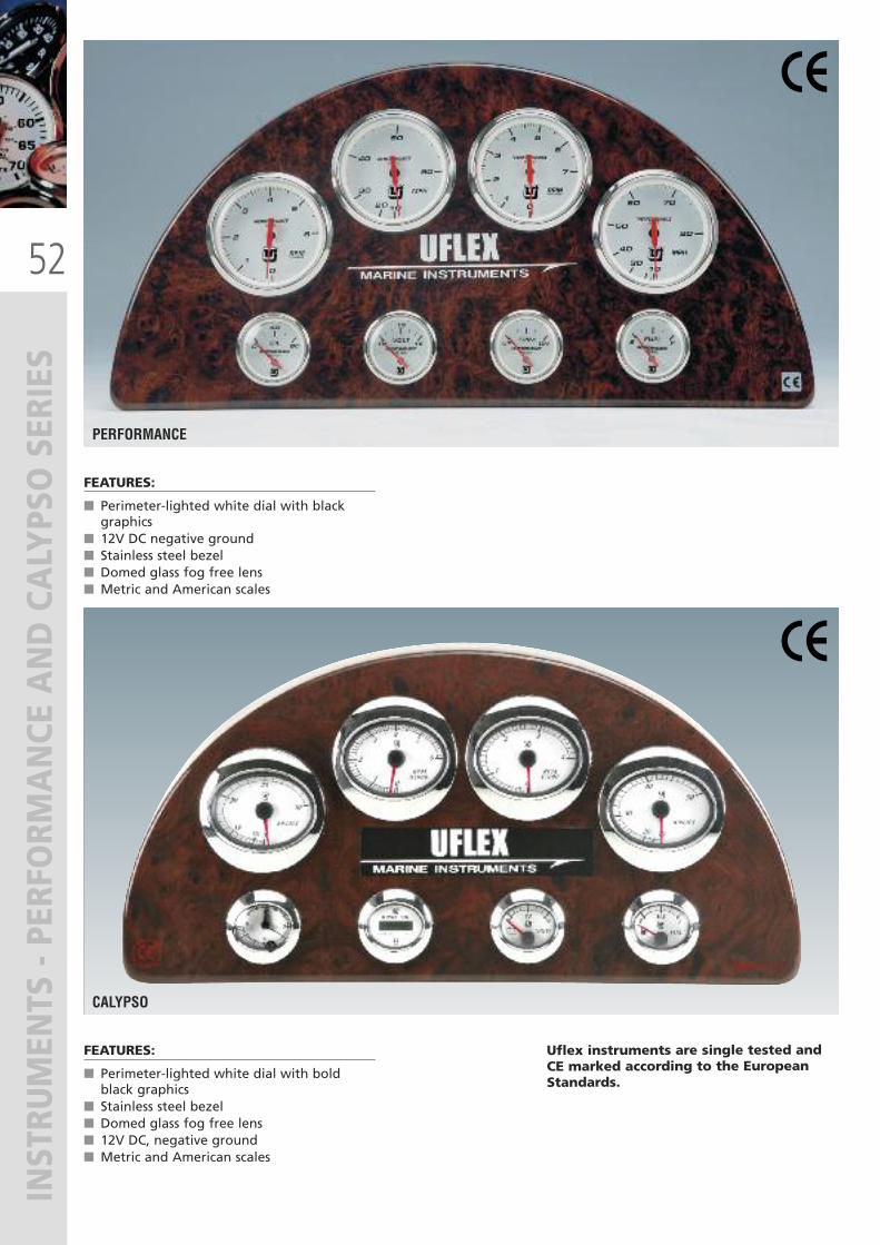
INSTRUMENTS - PERFORM
ANCE
AND CALYPSO SERIES
FEATURES:
� Perimeter-lighted white dial with blackgraphics
� 12V DC negative ground� Stainless steel bezel� Domed glass fog free lens� Metric and American scales
PERFORMANCE
FEATURES:
� Perimeter-lighted white dial with boldblack graphics
� Stainless steel bezel� Domed glass fog free lens� 12V DC, negative ground� Metric and American scales
CALYPSO
Uflex instruments are single tested andCE marked according to the EuropeanStandards.
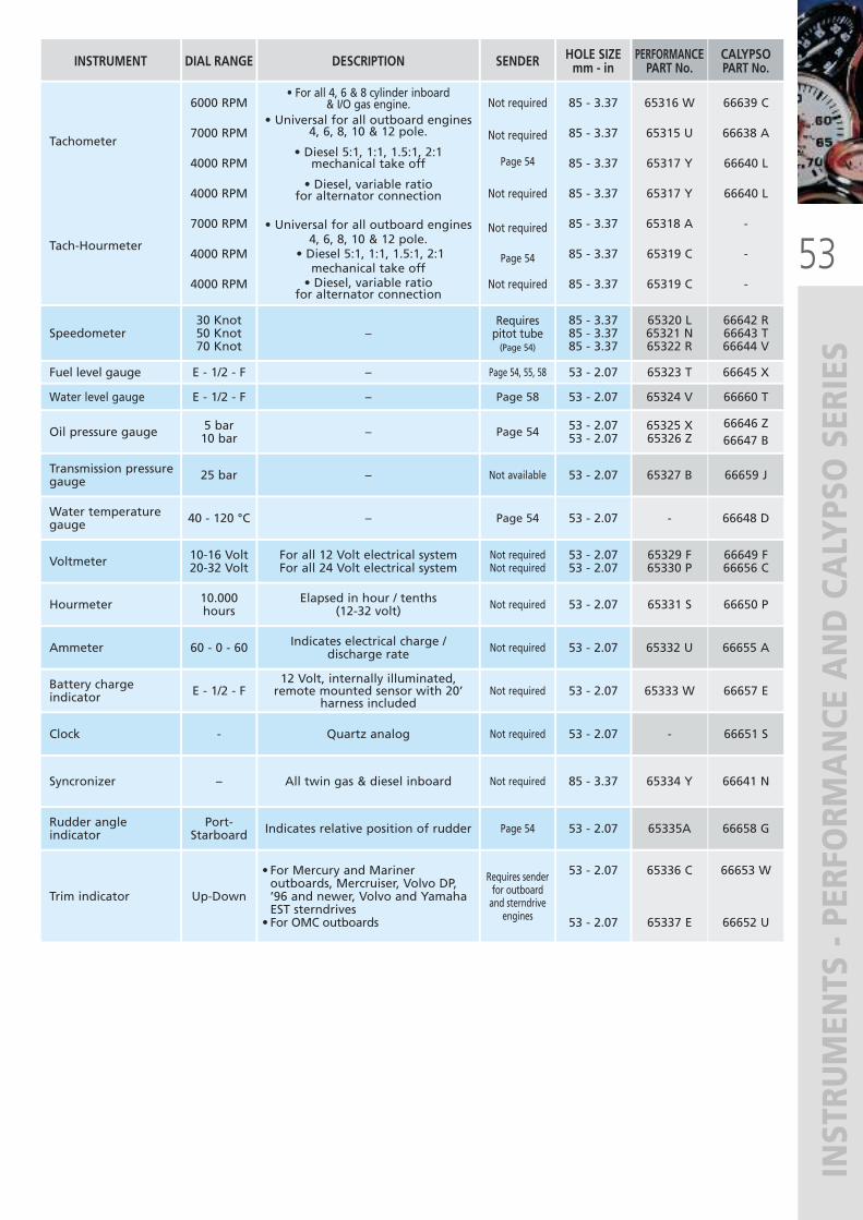
53
INSTRUMENTS - PERFORM
ANCE
AND CALYPSO SERIES
Voltmeter 10-16 Volt20-32 Volt
For all 12 Volt electrical systemFor all 24 Volt electrical system
Not requiredNot required
Hourmeter 10.000hours
Elapsed in hour / tenths (12-32 volt) Not required
Ammeter 60 - 0 - 60 Indicates electrical charge /discharge rate Not required
Clock - Quartz analog Not required
Syncronizer – All twin gas & diesel inboard Not required
Rudder angleindicator
Port-Starboard Indicates relative position of rudder Page 54
Trim indicator Up-Down
• For Mercury and Marineroutboards, Mercruiser, Volvo DP,’96 and newer, Volvo and YamahaEST sterndrives• For OMC outboards
Requires senderfor outboardand sterndrive
engines
65329 F65330 P
65331 S
65332 U
-
65334 Y
65335A
65336 C
65337 E
INSTRUMENT DIAL RANGE DESCRIPTION SENDER HOLE SIZEmm - in
Tachometer
Tach-Hourmeter
6000 RPM
7000 RPM
4000 RPM
4000 RPM
7000 RPM
4000 RPM
4000 RPM
• For all 4, 6 & 8 cylinder inboard & I/O gas engine.
• Universal for all outboard engines4, 6, 8, 10 & 12 pole.
• Diesel 5:1, 1:1, 1.5:1, 2:1mechanical take off
• Diesel, variable ratiofor alternator connection
• Universal for all outboard engines4, 6, 8, 10 & 12 pole.
• Diesel 5:1, 1:1, 1.5:1, 2:1mechanical take off• Diesel, variable ratio
for alternator connection
Not required
Not required
Page 54
Not required
Not required
Page 54
Not required
65316 W
65315 U
65317 Y
65317 Y
65318 A
65319 C
65319 C
Speedometer30 Knot50 Knot70 Knot
–Requirespitot tube(Page 54)
65320 L65321 N65322 R
Fuel level gauge E - 1/2 - F – Page 54, 55, 58 65323 T
Water level gauge E - 1/2 - F – Page 58 65324 V
Oil pressure gauge 5 bar10 bar – Page 54 65325 X
65326 Z
Transmission pressuregauge 25 bar – Not available 65327 B
Water temperaturegauge 40 - 120 °C – Page 54 -
PERFORMANCEPART No.
66649 F66656 C
66650 P
66655 A
66651 S
66641 N
66658 G
66653 W
66652 U
66639 C
66638 A
66640 L
66640 L
-
-
-
66642 R66643 T66644 V
66645 X
66660 T
66646 Z66647 B
66659 J
66648 D
CALYPSOPART No.
85 - 3.37
85 - 3.37
85 - 3.37
85 - 3.37
85 - 3.37
85 - 3.37
85 - 3.37
85 - 3.3785 - 3.3785 - 3.37
53 - 2.07
53 - 2.07
53 - 2.0753 - 2.07
53 - 2.07
53 - 2.07
53 - 2.0753 - 2.07
53 - 2.07
53 - 2.07
53 - 2.07
Battery chargeindicator E - 1/2 - F
12 Volt, internally illuminated,remote mounted sensor with 20’
harness includedNot required 65333 W 66657 E53 - 2.07
85 - 3.37
53 - 2.07
53 - 2.07
53 - 2.07
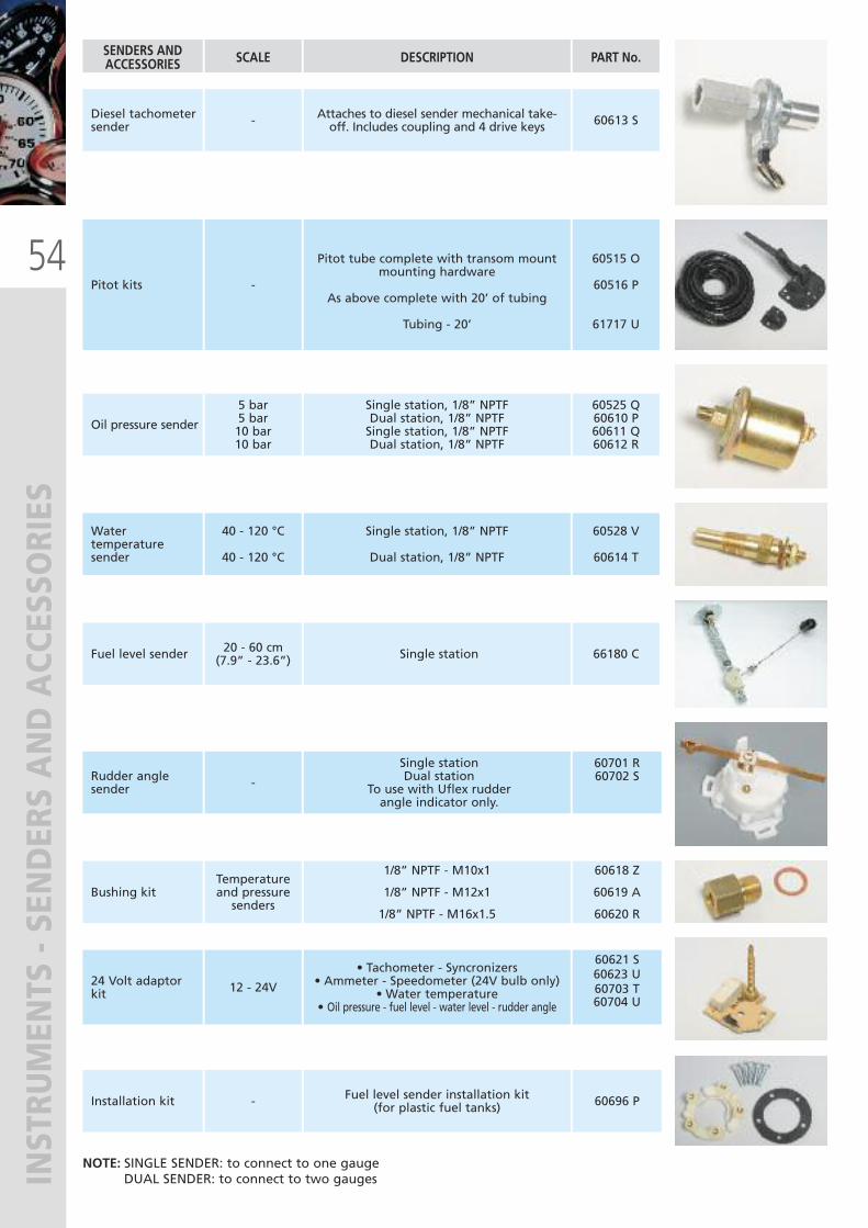
54
INSTRUMENTS - SENDERS AND ACCESSORIES
SENDERS AND ACCESSORIES SCALE DESCRIPTION PART No.
Diesel tachometersender - Attaches to diesel sender mechanical take-
off. Includes coupling and 4 drive keys 60613 S
Pitot kits -
Pitot tube complete with transom mountmounting hardware
As above complete with 20’ of tubing
Tubing - 20’
60515 O
60516 P
61717 U
Oil pressure sender
5 bar5 bar10 bar10 bar
Single station, 1/8” NPTFDual station, 1/8” NPTFSingle station, 1/8” NPTFDual station, 1/8” NPTF
60525 Q60610 P60611 Q60612 R
Watertemperaturesender
40 - 120 °C
40 - 120 °C
Single station, 1/8” NPTF
Dual station, 1/8” NPTF
60528 V
60614 T
Fuel level sender 20 - 60 cm(7.9” - 23.6”) Single station 66180 C
Bushing kitTemperatureand pressuresenders
1/8” NPTF - M10x1
1/8” NPTF - M12x1
1/8” NPTF - M16x1.5
60618 Z
60619 A
60620 R
24 Volt adaptorkit 12 - 24V
• Tachometer - Syncronizers• Ammeter - Speedometer (24V bulb only)
• Water temperature• Oil pressure - fuel level - water level - rudder angle
60621 S60623 U60703 T60704 U
Installation kit - Fuel level sender installation kit(for plastic fuel tanks) 60696 P
NOTE: SINGLE SENDER: to connect to one gauge DUAL SENDER: to connect to two gauges
Rudder anglesender -
Single stationDual station
To use with Uflex rudderangle indicator only.
60701 R60702 S
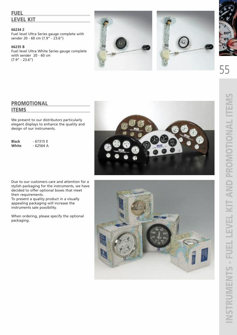
55
INSTRUMENTS
- FUEL LEVEL KIT AND PROMOTIONAL ITEM
S
FUELLEVEL KIT
66234 ZFuel level Ultra Series gauge complete withsender 20 - 60 cm (7.9” - 23.6”)
66235 BFuel level Ultra White Series gauge completewith sender 20 - 60 cm (7.9” - 23.6”)
PROMOTIONALITEMS
We present to our distributors particularlyelegant displays to enhance the quality anddesign of our instruments.
Black - 67315 EWhite - 62564 A
Due to our customers care and attention for astylish packaging for the instruments, we havedecided to offer optional boxes that meettheir requirements.To present a quality product in a visuallyappealing packaging will increase theinstruments sale possibility.
When ordering, please specify the optionalpackaging.
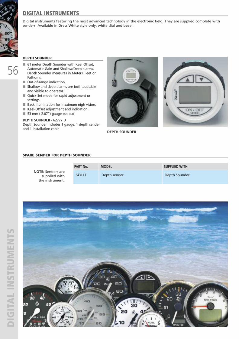
56
DIGITAL INSTRUMENTS
SPARE SENDER FOR DEPTH SOUNDER
DIGITAL INSTRUMENTS Digital instruments featuring the most advanced technology in the electronic field. They are supplied complete withsenders. Available in Dress White style only: white dial and bezel.
NOTE: Senders aresupplied with
the instrument.
MODEL SUPPLIED WITH:PART No.
Depth sender Depth Sounder64311 E
DEPTH SOUNDER
� 61 meter Depth Sounder with Keel Offset,Automatic Gain and Shallow/Deep alarms.Depth Sounder measures in Meters, Feet orFathoms.
� Out-of-range indication.� Shallow and deep alarms are both audiableand visible to operator.
� Quick-Set mode for rapid adjustment orsettings.
� Back illumination for maximum nigh vision.� Keel-Offset adjustment and indication.� 53 mm ( 2.07”) gauge cut out
DEPTH SOUNDER - 62777 UDepth Sounder includes 1 gauge. 1 depth senderand 1 installation cable.
DEPTH SOUNDER
57
MARINE MONITORING SYSTEM
S
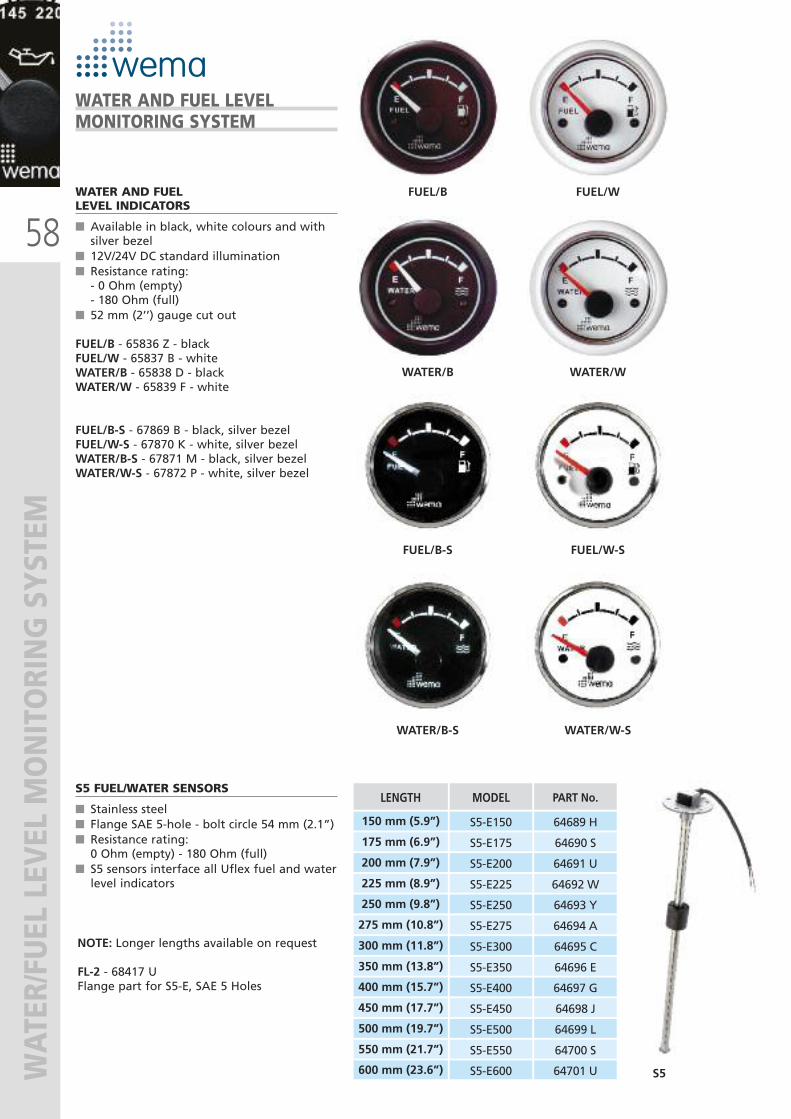
58
WATER/FUEL LEVEL MONITORING SYSTEM
WATER AND FUELLEVEL INDICATORS
� Available in black, white colours and withsilver bezel
� 12V/24V DC standard illumination� Resistance rating: - 0 Ohm (empty) - 180 Ohm (full)� 52 mm (2’’) gauge cut out
FUEL/B - 65836 Z - blackFUEL/W - 65837 B - whiteWATER/B - 65838 D - blackWATER/W - 65839 F - white
FUEL/B-S - 67869 B - black, silver bezelFUEL/W-S - 67870 K - white, silver bezelWATER/B-S - 67871 M - black, silver bezelWATER/W-S - 67872 P - white, silver bezel
S5 FUEL/WATER SENSORS
� Stainless steel� Flange SAE 5-hole - bolt circle 54 mm (2.1”)� Resistance rating: 0 Ohm (empty) - 180 Ohm (full) � S5 sensors interface all Uflex fuel and waterlevel indicators
NOTE: Longer lengths available on request
FL-2 - 68417 UFlange part for S5-E, SAE 5 Holes
S5
MODEL
S5-E150
S5-E175
S5-E200
S5-E225
PART No.
64689 H
64690 S
64691 U
64692 W
S5-E250
S5-E275
S5-E300
S5-E350
64693 Y
64694 A
64695 C
64696 E
S5-E400
S5-E450
S5-E500
S5-E550
64697 G
64698 J
64699 L
64700 S
S5-E600 64701 U
LENGTH
150 mm (5.9”)
175 mm (6.9”)
200 mm (7.9”)
225 mm (8.9”)
250 mm (9.8”)
275 mm (10.8”)
300 mm (11.8”)
350 mm (13.8”)
400 mm (15.7”)
450 mm (17.7”)
500 mm (19.7”)
550 mm (21.7”)
600 mm (23.6”)
WATER AND FUEL LEVELMONITORING SYSTEM
FUEL/W-SFUEL/B-S
WATER/W-SWATER/B-S
FUEL/WFUEL/B
WATER/WWATER/B
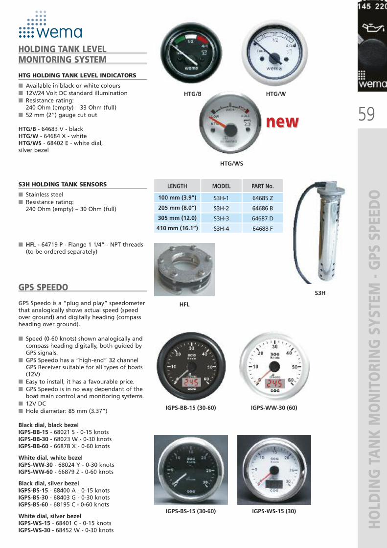
HTG/WS
59
HOLDING TANK MONITORING SYSTEM - GPS SPEEDO
HTG HOLDING TANK LEVEL INDICATORS
� Available in black or white colours � 12V/24 Volt DC standard illumination� Resistance rating: 240 Ohm (empty) – 33 Ohm (full) � 52 mm (2’’) gauge cut out
HTG/B - 64683 V - blackHTG/W - 64684 X - whiteHTG/WS - 68402 E - white dial, silver bezel
HOLDING TANK LEVELMONITORING SYSTEM
HTG/WHTG/B
IGPS-WW-30 (60)IGPS-BB-15 (30-60)
IGPS-WS-15 (30)IGPS-BS-15 (30-60)
S3H HOLDING TANK SENSORS
� Stainless steel� Resistance rating: 240 Ohm (empty) – 30 Ohm (full)
� HFL - 64719 P - Flange 1 1/4” - NPT threads (to be ordered separately)
LENGTH MODEL
100 mm (3.9”) S3H-1
205 mm (8.0”) S3H-2
305 mm (12.0) S3H-3
410 mm (16.1”) S3H-4
PART No.
64685 Z
64686 B
64687 D
64688 F
GPS SPEEDO
GPS Speedo is a “plug and play” speedometerthat analogically shows actual speed (speedover ground) and digitally heading (compassheading over ground).
� Speed (0-60 knots) shown analogically andcompass heading digitally, both guided byGPS signals.
� GPS Speedo has a “high-end” 32 channelGPS Receiver suitable for all types of boats(12V)
� Easy to install, it has a favourable price.� GPS Speedo is in no way dependant of theboat main control and monitoring systems.
� 12V DC� Hole diameter: 85 mm (3.37”)
Black dial, black bezelIGPS-BB-15 - 68021 S - 0-15 knotsIGPS-BB-30 - 68023 W - 0-30 knotsIGPS-BB-60 - 66878 X - 0-60 knots
White dial, white bezelIGPS-WW-30 - 68024 Y - 0-30 knotsIGPS-WW-60 - 66879 Z - 0-60 knots
Black dial, silver bezelIGPS-BS-15 - 68400 A - 0-15 knotsIGPS-BS-30 - 68403 G - 0-30 knotsIGPS-BS-60 - 68195 C - 0-60 knots
White dial, silver bezelIGPS-WS-15 - 68401 C - 0-15 knotsIGPS-WS-30 - 68452 W - 0-30 knots
HFL
S3H
new new
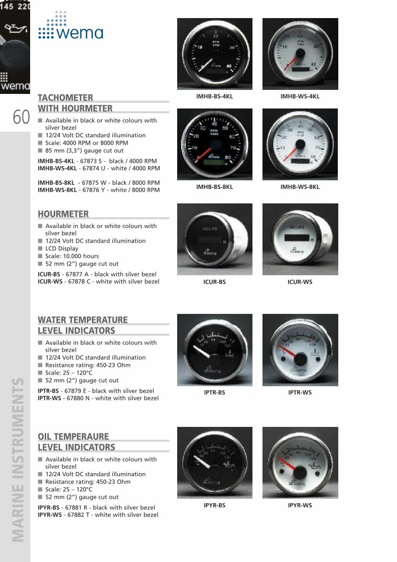
60
MARINE INSTRUMENTS
TACHOMETERWITH HOURMETER� Available in black or white colours withsilver bezel
� 12/24 Volt DC standard illumination� Scale: 4000 RPM or 8000 RPM � 85 mm (3,3”) gauge cut out
IMHB-BS-4KL - 67873 S - black / 4000 RPMIMHB-WS-4KL - 67874 U - white / 4000 RPM
IMHB-BS-8KL - 67875 W - black / 8000 RPMIMHB-WS-8KL - 67876 Y - white / 8000 RPM
HOURMETER� Available in black or white colours withsilver bezel
� 12/24 Volt DC standard illumination� LCD Display� Scale: 10.000 hours � 52 mm (2”) gauge cut out
ICUR-BS - 67877 A - black with silver bezelICUR-WS - 67878 C - white with silver bezel
WATER TEMPERATURELEVEL INDICATORS� Available in black or white colours withsilver bezel
� 12/24 Volt DC standard illumination� Resistance rating: 450-23 Ohm � Scale: 25 – 120°C � 52 mm (2”) gauge cut out
IPTR-BS - 67879 E - black with silver bezelIPTR-WS - 67880 N - white with silver bezel
OIL TEMPERAURELEVEL INDICATORS� Available in black or white colours withsilver bezel
� 12/24 Volt DC standard illumination� Resistance rating: 450-23 Ohm� Scale: 25 – 120°C� 52 mm (2”) gauge cut out
IPYR-BS - 67881 R - black with silver bezelIPYR-WS - 67882 T - white with silver bezel
IMHB-WS-4KLIMHB-BS-4KL
IMHB-WS-8KLIMHB-BS-8KL
ICUR-WSICUR-BS
IPTR-WSIPTR-BS
IPYR-WSIPYR-BS
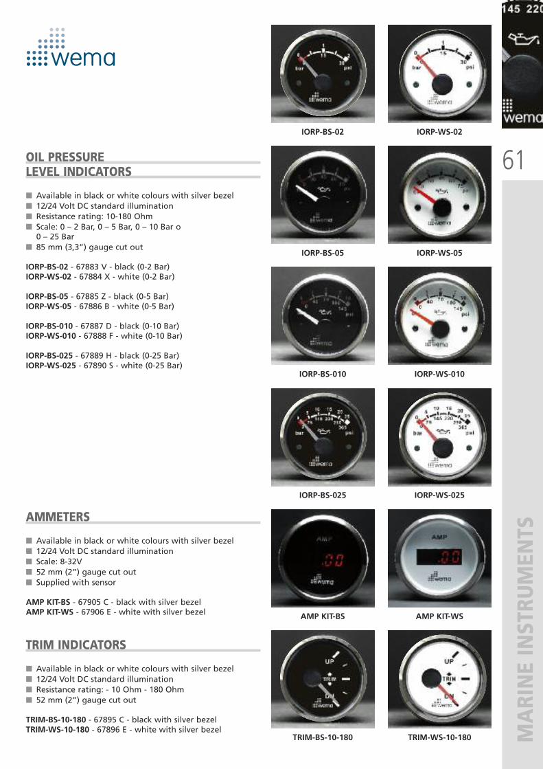
61
MARINE INSTRUMENTS
OIL PRESSURELEVEL INDICATORS
� Available in black or white colours with silver bezel� 12/24 Volt DC standard illumination� Resistance rating: 10-180 Ohm � Scale: 0 – 2 Bar, 0 – 5 Bar, 0 – 10 Bar o 0 – 25 Bar
� 85 mm (3,3”) gauge cut out
IORP-BS-02 - 67883 V - black (0-2 Bar)IORP-WS-02 - 67884 X - white (0-2 Bar)
IORP-BS-05 - 67885 Z - black (0-5 Bar)IORP-WS-05 - 67886 B - white (0-5 Bar)
IORP-BS-010 - 67887 D - black (0-10 Bar)IORP-WS-010 - 67888 F - white (0-10 Bar)
IORP-BS-025 - 67889 H - black (0-25 Bar)IORP-WS-025 - 67890 S - white (0-25 Bar)
AMMETERS
� Available in black or white colours with silver bezel� 12/24 Volt DC standard illumination� Scale: 8-32V� 52 mm (2”) gauge cut out� Supplied with sensor
AMP KIT-BS - 67905 C - black with silver bezelAMP KIT-WS - 67906 E - white with silver bezel
TRIM INDICATORS
� Available in black or white colours with silver bezel� 12/24 Volt DC standard illumination� Resistance rating: - 10 Ohm - 180 Ohm � 52 mm (2”) gauge cut out
TRIM-BS-10-180 - 67895 C - black with silver bezelTRIM-WS-10-180 - 67896 E - white with silver bezel
IORP-WS-05IORP-BS-05
IORP-WS-010IORP-BS-010
AMP KIT-WSAMP KIT-BS
IORP-WS-02IORP-BS-02
IORP-WS-025IORP-BS-025
TRIM-WS-10-180TRIM-BS-10-180
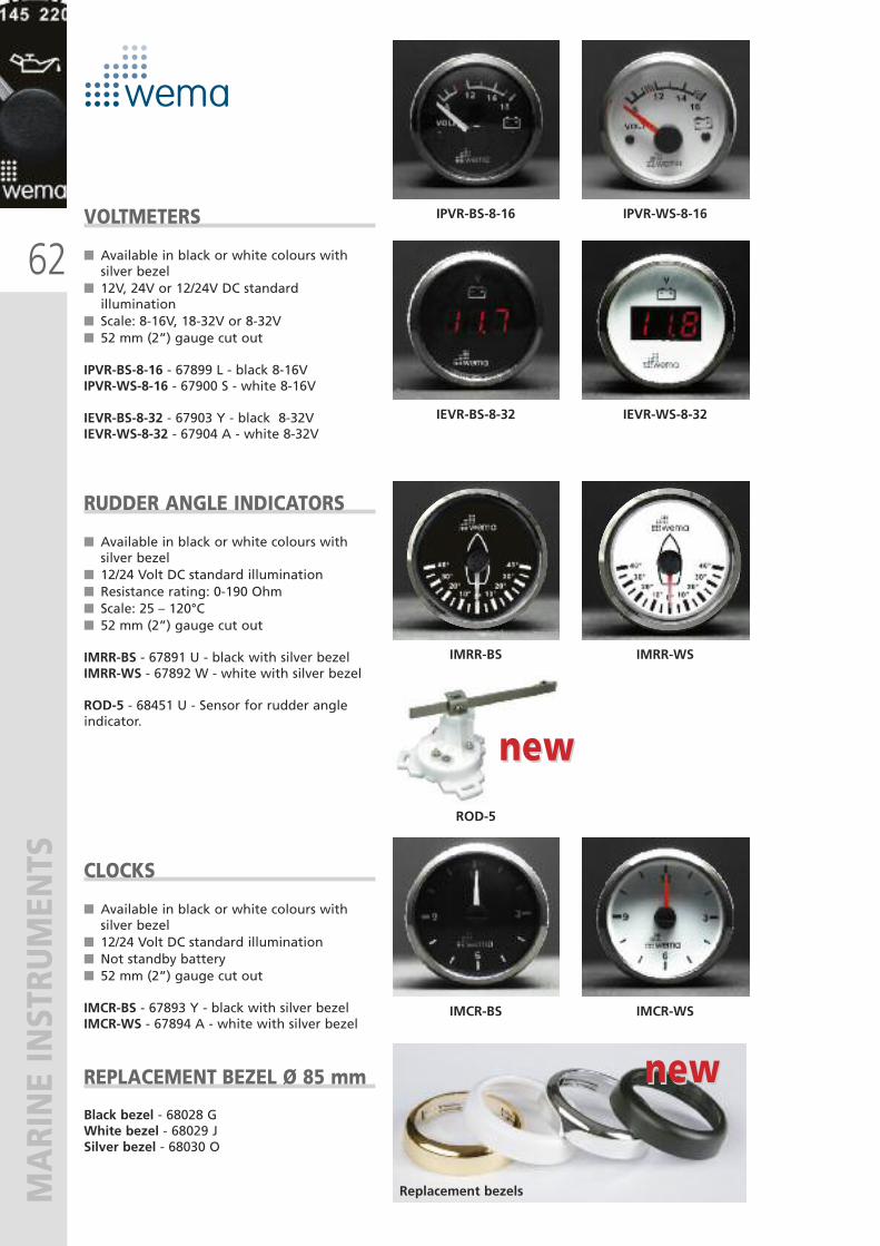
62
MARINE INSTRUMENTS
VOLTMETERS
� Available in black or white colours withsilver bezel
� 12V, 24V or 12/24V DC standardillumination
� Scale: 8-16V, 18-32V or 8-32V� 52 mm (2”) gauge cut out
IPVR-BS-8-16 - 67899 L - black 8-16VIPVR-WS-8-16 - 67900 S - white 8-16V
IEVR-BS-8-32 - 67903 Y - black 8-32VIEVR-WS-8-32 - 67904 A - white 8-32V
RUDDER ANGLE INDICATORS
� Available in black or white colours withsilver bezel
� 12/24 Volt DC standard illumination� Resistance rating: 0-190 Ohm� Scale: 25 – 120°C� 52 mm (2”) gauge cut out
IMRR-BS - 67891 U - black with silver bezelIMRR-WS - 67892 W - white with silver bezel
ROD-5 - 68451 U - Sensor for rudder angleindicator.
CLOCKS
� Available in black or white colours withsilver bezel
� 12/24 Volt DC standard illumination� Not standby battery� 52 mm (2”) gauge cut out
IMCR-BS - 67893 Y - black with silver bezelIMCR-WS - 67894 A - white with silver bezel
REPLACEMENT BEZEL Ø 85 mm
Black bezel - 68028 GWhite bezel - 68029 JSilver bezel - 68030 O
IMCR-WSIMCR-BS
IPVR-WS-8-16IPVR-BS-8-16
IEVR-WS-8-32IEVR-BS-8-32
IMRR-WSIMRR-BS
ROD-5
Replacement bezels
new new
new new

63
FRESH WATER AND BILGE PUMPS
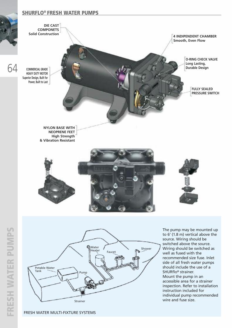
The pump may be mounted upto 6’ (1.8 m) vertical above thesource. Wiring should beswitched above the source.Wiring should be switched aswell as fused with therecommended size fuse. Inletside of all fresh water pumpsshould include the use of aSHURflo® strainer. Mount the pump in anaccessible area for a strainerinspection. Refer to installationinstruction included forindividual pump recommendedwire and fuse size.
Potable WaterTank Pump
Faucet Shower
Strainer
WaterHeater
64
FRESH WATER PUMPS
SHURFLO® FRESH WATER PUMPS
DIE CAST COMPONETS
Solid Construction
COMMERCIAL GRADEHEAVY DUTY MOTOR
Superior Design, Built forPower, Built to Last
NYLON BASE WITH NEOPRENE FEETHigh Strength
& Vibration Resistant
4 INDIPENDENT CHAMBERSmooth, Even Flow
O-RING CHECK VALVELong Lasting,Durable Design
FULLY SEALEDPRESSURE SWITCH
FRESH WATER MULTI-FIXTURE SYSTEMS
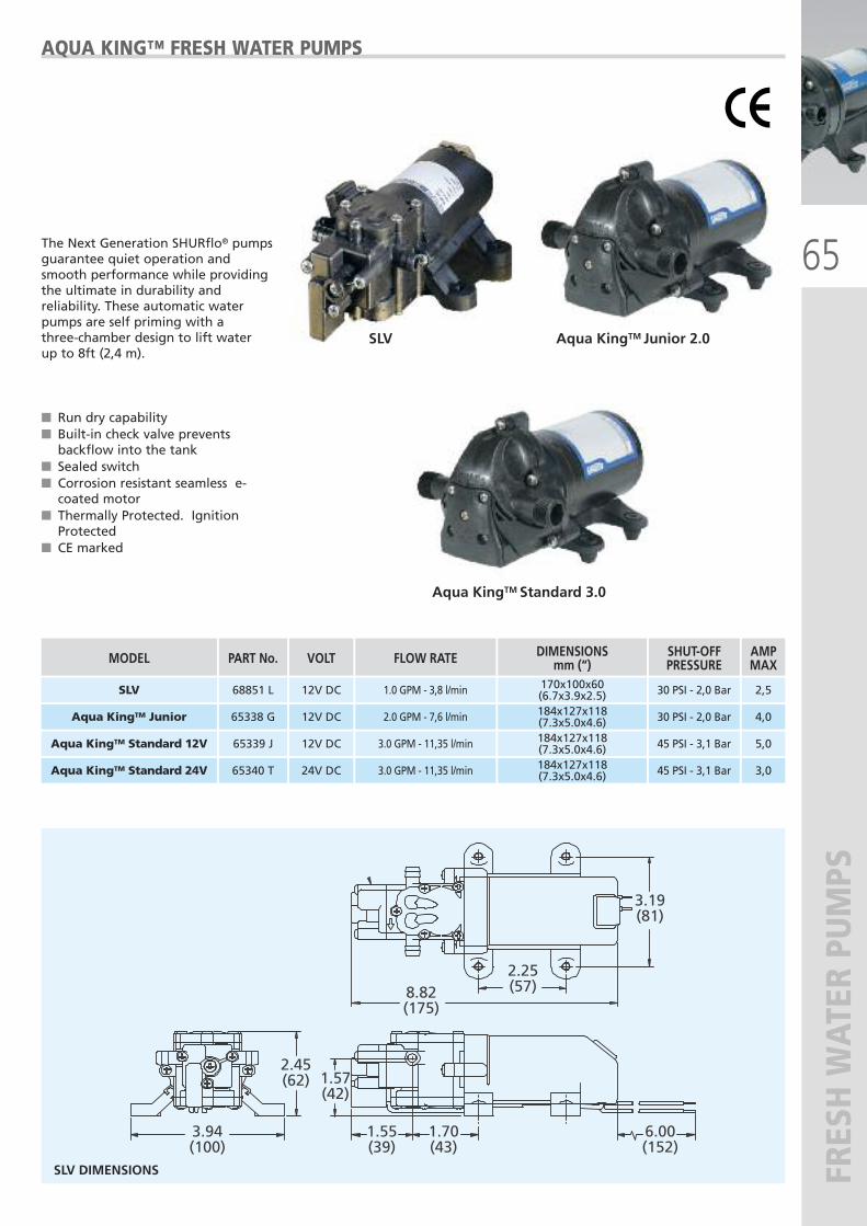
65
FRESH WATER PUMPS
Aqua KingTM Standard 3.0
SLV Aqua KingTM Junior 2.0
AQUA KING™ FRESH WATER PUMPS
� Run dry capability� Built-in check valve preventsbackflow into the tank
� Sealed switch � Corrosion resistant seamless e-coated motor
� Thermally Protected. IgnitionProtected
� CE marked
The Next Generation SHURflo® pumpsguarantee quiet operation andsmooth performance while providingthe ultimate in durability andreliability. These automatic waterpumps are self priming with a three-chamber design to lift water up to 8ft (2,4 m).
3.94(100)
2.45(62) 1.57
(42)
1.55(39)
1.70(43)
6.00(152)
3.19(81)
2.25(57)8.82
(175)
SLV DIMENSIONS
PART No. DIMENSIONSmm (“)
65338 G 184x127x118(7.3x5.0x4.6)
65339 J 184x127x118(7.3x5.0x4.6)
65340 T 184x127x118(7.3x5.0x4.6)
VOLT
12V DC
12V DC
24V DC
FLOW RATE
2.0 GPM - 7,6 l/min
3.0 GPM - 11,35 l/min
3.0 GPM - 11,35 l/min
MODEL
Aqua KingTM Junior
Aqua KingTM Standard 12V
Aqua KingTM Standard 24V
AMPMAX
4,0
5,0
3,0
SHUT-OFFPRESSURE
30 PSI - 2,0 Bar
68851 L 170x100x60(6.7x3.9x2.5)12V DC 1.0 GPM - 3,8 l/minSLV 2,530 PSI - 2,0 Bar
45 PSI - 3,1 Bar
45 PSI - 3,1 Bar
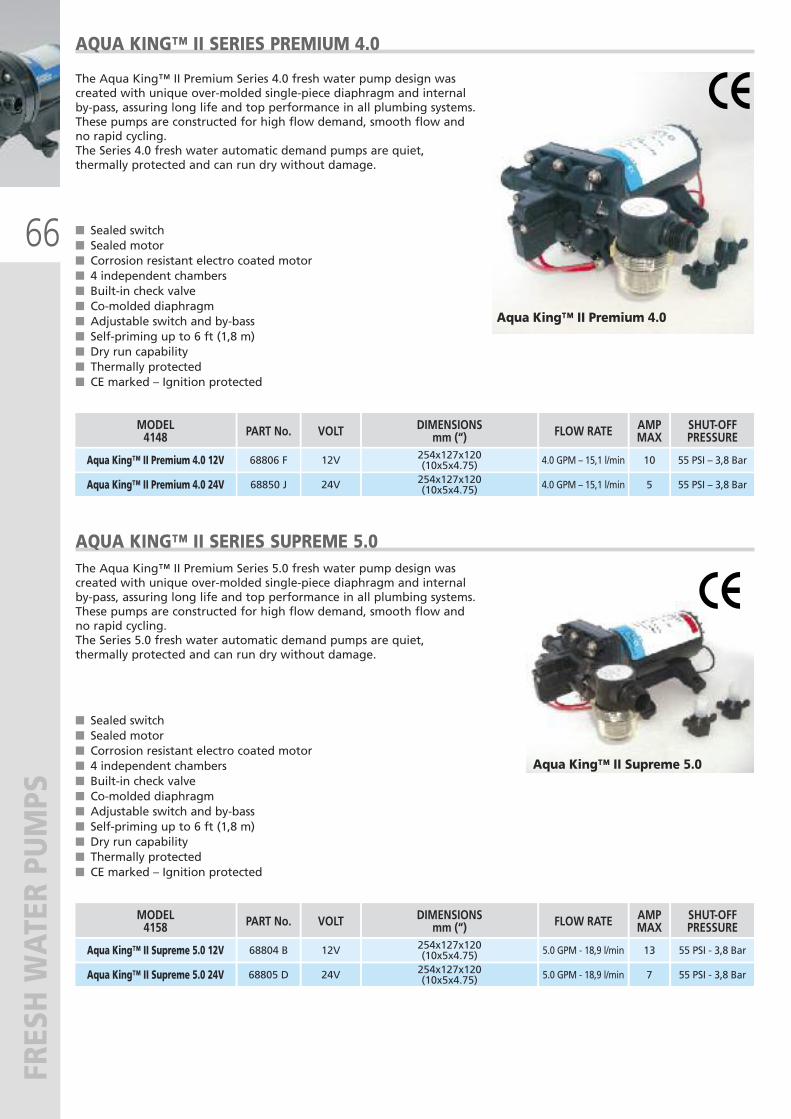
66
FRESH WATER PUMPS
AQUA KING™ II SERIES PREMIUM 4.0
The Aqua King™ II Premium Series 4.0 fresh water pump design wascreated with unique over-molded single-piece diaphragm and internalby-pass, assuring long life and top performance in all plumbing systems.These pumps are constructed for high flow demand, smooth flow andno rapid cycling.The Series 4.0 fresh water automatic demand pumps are quiet,thermally protected and can run dry without damage.
� Sealed switch� Sealed motor� Corrosion resistant electro coated motor� 4 independent chambers� Built-in check valve� Co-molded diaphragm� Adjustable switch and by-bass� Self-priming up to 6 ft (1,8 m)� Dry run capability� Thermally protected� CE marked – Ignition protected
Aqua King™ II Premium 4.0
PART No. DIMENSIONSmm (“)
68806 F 254x127x120(10x5x4.75)
VOLT
12V
FLOW RATE
4.0 GPM – 15,1 l/min
MODEL4148
Aqua King™ II Premium 4.0 12V
AMPMAX
10
SHUT-OFFPRESSURE
55 PSI – 3,8 Bar
68850 J 254x127x120(10x5x4.75)24V 4.0 GPM – 15,1 l/minAqua King™ II Premium 4.0 24V 5 55 PSI – 3,8 Bar
Aqua King™ II Supreme 5.0
AQUA KING™ II SERIES SUPREME 5.0The Aqua King™ II Premium Series 5.0 fresh water pump design wascreated with unique over-molded single-piece diaphragm and internalby-pass, assuring long life and top performance in all plumbing systems.These pumps are constructed for high flow demand, smooth flow andno rapid cycling.The Series 5.0 fresh water automatic demand pumps are quiet,thermally protected and can run dry without damage.
� Sealed switch� Sealed motor� Corrosion resistant electro coated motor� 4 independent chambers� Built-in check valve� Co-molded diaphragm� Adjustable switch and by-bass� Self-priming up to 6 ft (1,8 m)� Dry run capability� Thermally protected� CE marked – Ignition protected
PART No. DIMENSIONSmm (“)VOLT FLOW RATE MODEL
4158AMPMAX
SHUT-OFFPRESSURE
68804 B 254x127x120(10x5x4.75)12V 5.0 GPM - 18,9 l/minAqua King™ II Supreme 5.0 12V 13 55 PSI - 3,8 Bar
68805 D 254x127x120(10x5x4.75)24V 5.0 GPM - 18,9 l/minAqua King™ II Supreme 5.0 24V 7 55 PSI - 3,8 Bar
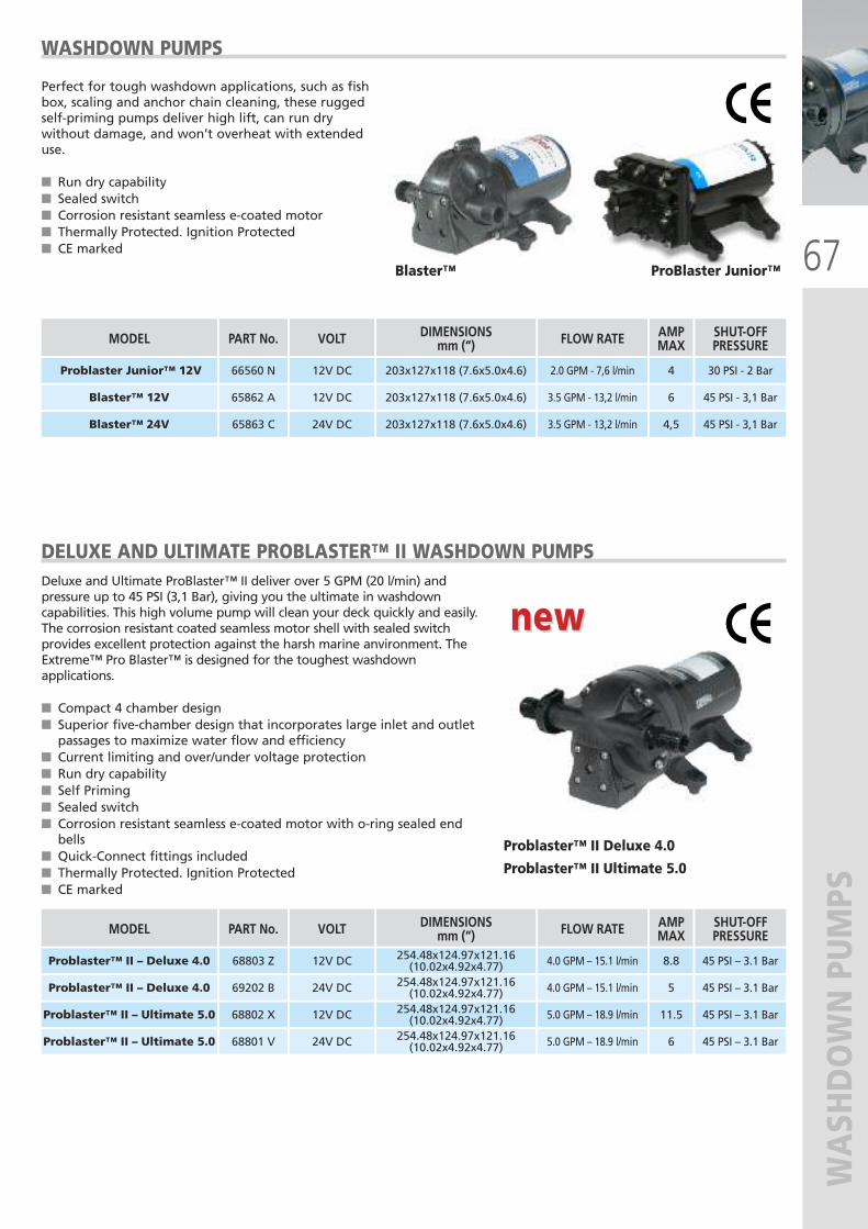
67
WASHDOWN PUMPS
WASHDOWN PUMPS
Perfect for tough washdown applications, such as fishbox, scaling and anchor chain cleaning, these ruggedself-priming pumps deliver high lift, can run drywithout damage, and won’t overheat with extendeduse.
� Run dry capability� Sealed switch � Corrosion resistant seamless e-coated motor� Thermally Protected. Ignition Protected� CE marked
Blaster™ ProBlaster Junior™
PART No. DIMENSIONSmm (“)
65862 A 203x127x118 (7.6x5.0x4.6)
65863 C 203x127x118 (7.6x5.0x4.6)
VOLT
12V DC
24V DC
FLOW RATE
3.5 GPM - 13,2 l/min
3.5 GPM - 13,2 l/min
MODEL
Blaster™ 12V
Blaster™ 24V
AMPMAX
6
4,5
SHUT-OFFPRESSURE
45 PSI - 3,1 Bar
66560 N 203x127x118 (7.6x5.0x4.6)12V DC 2.0 GPM - 7,6 l/minProblaster Junior™ 12V 4 30 PSI - 2 Bar
45 PSI - 3,1 Bar
DELUXE AND ULTIMATE PROBLASTER™ II WASHDOWN PUMPSDeluxe and Ultimate ProBlaster™ II deliver over 5 GPM (20 l/min) andpressure up to 45 PSI (3,1 Bar), giving you the ultimate in washdowncapabilities. This high volume pump will clean your deck quickly and easily.The corrosion resistant coated seamless motor shell with sealed switchprovides excellent protection against the harsh marine anvironment. TheExtreme™ Pro Blaster™ is designed for the toughest washdownapplications.
� Compact 4 chamber design� Superior five-chamber design that incorporates large inlet and outletpassages to maximize water flow and efficiency
� Current limiting and over/under voltage protection� Run dry capability� Self Priming � Sealed switch � Corrosion resistant seamless e-coated motor with o-ring sealed endbells
� Quick-Connect fittings included� Thermally Protected. Ignition Protected� CE marked
Problaster™ II Deluxe 4.0
Problaster™ II Ultimate 5.0
new new
PART No. DIMENSIONSmm (“)VOLT FLOW RATE MODEL AMP
MAXSHUT-OFFPRESSURE
68803 Z 254.48x124.97x121.16(10.02x4.92x4.77)12V DC 4.0 GPM – 15.1 l/minProblaster™ II – Deluxe 4.0 8.8 45 PSI – 3.1 Bar
69202 B 254.48x124.97x121.16(10.02x4.92x4.77)24V DC 4.0 GPM – 15.1 l/minProblaster™ II – Deluxe 4.0 5 45 PSI – 3.1 Bar
68802 X 254.48x124.97x121.16(10.02x4.92x4.77)12V DC 5.0 GPM – 18.9 l/minProblaster™ II – Ultimate 5.0 11.5 45 PSI – 3.1 Bar
68801 V 254.48x124.97x121.16(10.02x4.92x4.77)24V DC 5.0 GPM – 18.9 l/minProblaster™ II – Ultimate 5.0 6 45 PSI – 3.1 Bar
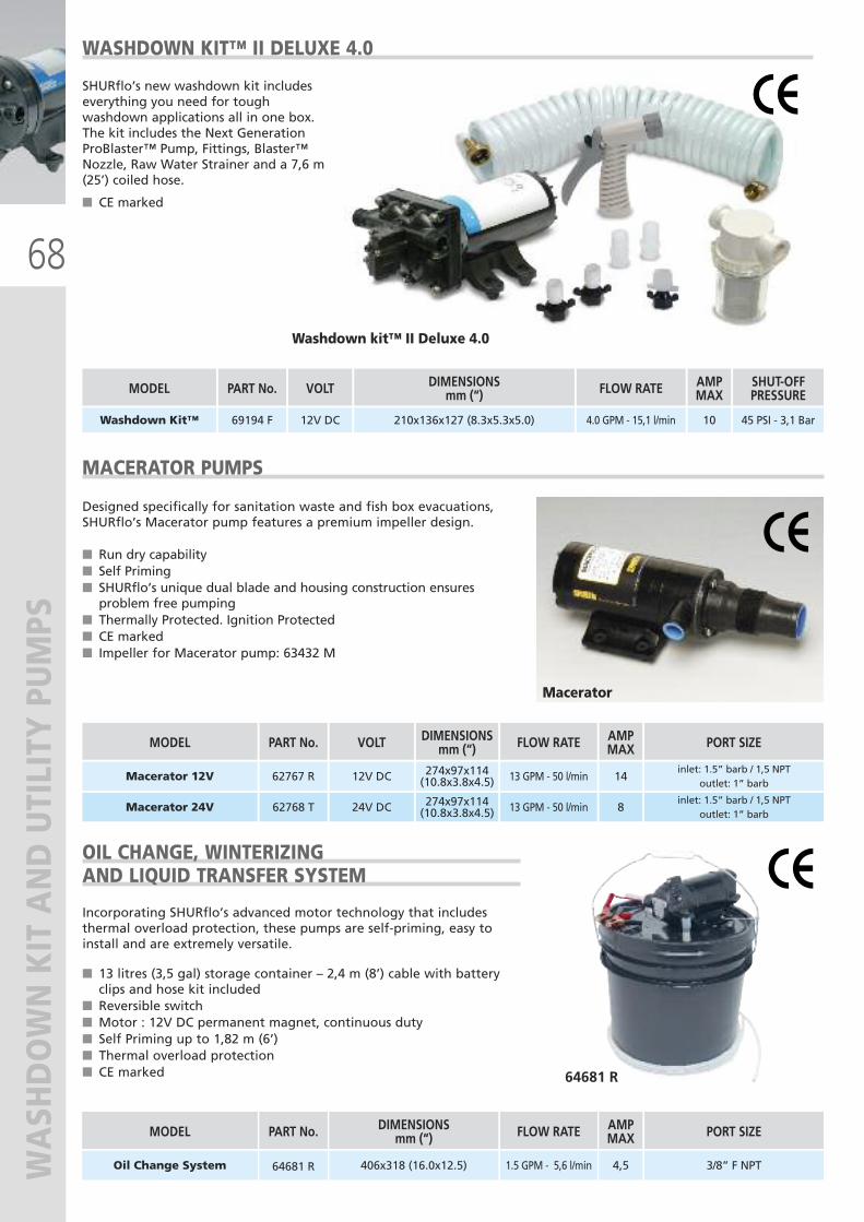
68
WASHDOWN KIT AND UTILITY PUMPS
SHURflo’s new washdown kit includeseverything you need for toughwashdown applications all in one box.The kit includes the Next GenerationProBlaster™ Pump, Fittings, Blaster™Nozzle, Raw Water Strainer and a 7,6 m(25’) coiled hose.
� CE marked
WASHDOWN KIT™ II DELUXE 4.0
Washdown kit™ II Deluxe 4.0
PART No. DIMENSIONSmm (“)
69194 F 210x136x127 (8.3x5.3x5.0)
VOLT
12V DC
FLOW RATE
4.0 GPM - 15,1 l/min
MODEL
Washdown Kit™
AMPMAX
10
SHUT-OFFPRESSURE
45 PSI - 3,1 Bar
DIMENSIONImm (“)
406x318 (16.0x12.5)
CODICE
64681 R
PORTATA
1.5 GPM - 5,6 l/min
MODEL
Sistema Cambio Olio
AMPMAX
4,5
RACCORDI
3/8” F NPT
MACERATOR PUMPS
Designed specifically for sanitation waste and fish box evacuations,SHURflo’s Macerator pump features a premium impeller design.
� Run dry capability� Self Priming � SHURflo’s unique dual blade and housing construction ensuresproblem free pumping
� Thermally Protected. Ignition Protected� CE marked� Impeller for Macerator pump: 63432 M
Macerator
274x97x114(10.8x3.8x4.5)62767 R 12V DC 13 GPM - 50 l/minMacerator 12V 14
inlet: 1.5” barb / 1,5 NPToutlet: 1” barb
274x97x114(10.8x3.8x4.5)62768 T 24V DC 13 GPM - 50 l/minMacerator 24V 8
inlet: 1.5” barb / 1,5 NPToutlet: 1” barb
406x318 (16.0x12.5)64681 R 1.5 GPM - 5,6 l/minOil Change System 4,5 3/8” F NPT
64681 R
OIL CHANGE, WINTERIZINGAND LIQUID TRANSFER SYSTEM
Incorporating SHURflo’s advanced motor technology that includesthermal overload protection, these pumps are self-priming, easy toinstall and are extremely versatile.
� 13 litres (3,5 gal) storage container – 2,4 m (8’) cable with batteryclips and hose kit included
� Reversible switch � Motor : 12V DC permanent magnet, continuous duty� Self Priming up to 1,82 m (6’)� Thermal overload protection� CE marked
DIMENSIONSmm (“)PART No. VOLT FLOW RATE MODEL AMP
MAX PORT SIZE
DIMENSIONSmm (“)PART No. FLOW RATE MODEL AMP
MAX PORT SIZE
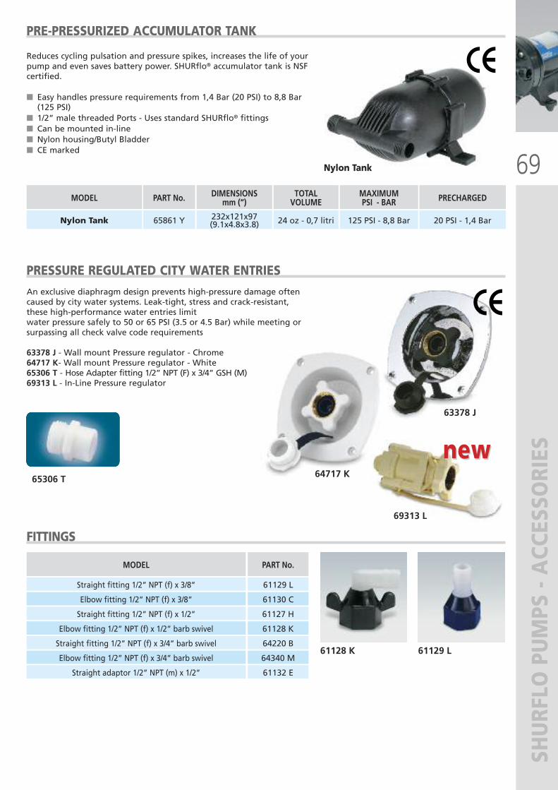
69
SHURFLO PUMPS - ACCESSORIES
PRE-PRESSURIZED ACCUMULATOR TANK
Reduces cycling pulsation and pressure spikes, increases the life of yourpump and even saves battery power. SHURflo® accumulator tank is NSFcertified.
� Easy handles pressure requirements from 1,4 Bar (20 PSI) to 8,8 Bar(125 PSI)
� 1/2” male threaded Ports - Uses standard SHURflo® fittings� Can be mounted in-line� Nylon housing/Butyl Bladder� CE marked
Nylon Tank
TOTALVOLUME
24 oz - 0,7 litri
MODEL
Nylon Tank
MAXIMUM PSI - BAR
125 PSI - 8,8 Bar
DIMENSIONSmm (“)
232x121x97(9.1x4.8x3.8)
PRECHARGED
20 PSI - 1,4 Bar
PART No.
65861 Y
PRESSURE REGULATED CITY WATER ENTRIESAn exclusive diaphragm design prevents high-pressure damage oftencaused by city water systems. Leak-tight, stress and crack-resistant,these high-performance water entries limitwater pressure safely to 50 or 65 PSI (3.5 or 4.5 Bar) while meeting orsurpassing all check valve code requirements
63378 J - Wall mount Pressure regulator - Chrome64717 K- Wall mount Pressure regulator - White65306 T - Hose Adapter fitting 1/2” NPT (F) x 3/4” GSH (M)69313 L - In-Line Pressure regulator
63378 J
64717 K65306 T
69313 L
new new
FITTINGS
MODEL
Straight fitting 1/2” NPT (f) x 3/8”
PART No.
61129 L
Elbow fitting 1/2” NPT (f) x 3/8” 61130 C
Straight fitting 1/2” NPT (f) x 1/2” 61127 H
Elbow fitting 1/2” NPT (f) x 1/2” barb swivel 61128 K
Straight fitting 1/2” NPT (f) x 3/4” barb swivel 64220 B
Elbow fitting 1/2” NPT (f) x 3/4” barb swivel 64340 M
Straight adaptor 1/2” NPT (m) x 1/2” 61132 E
61128 K 61129 L
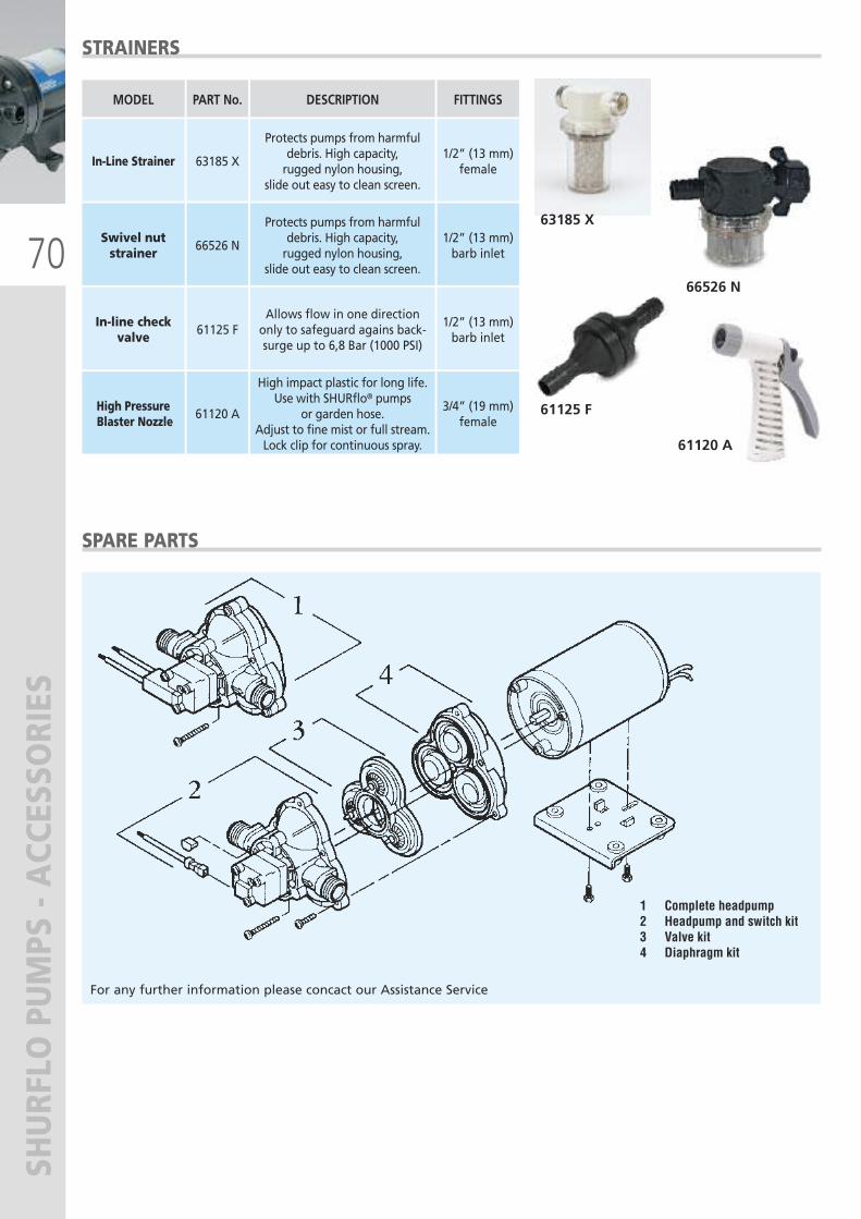
70
SHURFLO PUMPS - ACCESSORIES
SPARE PARTS
1 Complete headpump 2 Headpump and switch kit 3 Valve kit4 Diaphragm kit
For any further information please concact our Assistance Service
STRAINERS
FITTINGSMODEL DESCRIPTIONPART No.
1/2” (13 mm)barb inlet
Swivel nut strainer
Protects pumps from harmfuldebris. High capacity, rugged nylon housing,
slide out easy to clean screen.
66526 N
1/2” (13 mm)barb inlet
In-line checkvalve
Allows flow in one directiononly to safeguard agains back-surge up to 6,8 Bar (1000 PSI)
61125 F
3/4” (19 mm)female
High PressureBlaster Nozzle
High impact plastic for long life.Use with SHURflo® pumps
or garden hose. Adjust to fine mist or full stream.Lock clip for continuous spray.
61120 A
1/2” (13 mm)female
In-Line Strainer
Protects pumps from harmfuldebris. High capacity, rugged nylon housing,
slide out easy to clean screen.
63185 X
63185 X
61125 F
66526 N
61120 A
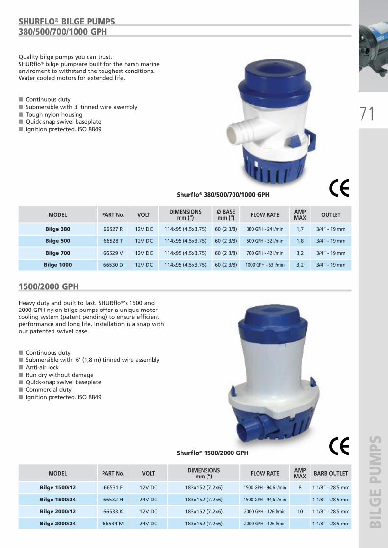
71
BILGE PUMPS
SHURFLO® BILGE PUMPS380/500/700/1000 GPH
Quality bilge pumps you can trust. SHURflo® bilge pumpsare built for the harsh marineenviroment to withstand the toughest conditions.Water cooled motors for extended life.
� Continuous duty� Submersible with 3’ tinned wire assembly� Tough nylon housing� Quick-snap swivel baseplate� Ignition pretected. ISO 8849
Shurflo® 380/500/700/1000 GPH
66528 T 114x95 (4.5x3.75)
66529 V 114x95 (4.5x3.75)
66530 D 114x95 (4.5x3.75)
12V DC
12V DC
12V DC
500 GPH - 32 l/min
700 GPH - 42 l/min
1000 GPH - 63 l/min
Bilge 500
Bilge 700
Bilge 1000
1,8
3,2
3,2
3/4” - 19 mm
66527 R 114x95 (4.5x3.75)
60 (2 3/8)
60 (2 3/8)
60 (2 3/8)
60 (2 3/8)12V DC 380 GPH - 24 l/minBilge 380 1,7 3/4” - 19 mm
3/4” - 19 mm
3/4” - 19 mm
1500/2000 GPH
Heavy duty and built to last. SHURflo®’s 1500 and2000 GPH nylon bilge pumps offer a unique motorcooling system (patent pending) to ensure efficientperformance and long life. Installation is a snap withour patented swivel base.
� Continuous duty� Submersible with 6’ (1,8 m) tinned wire assembly� Anti-air lock� Run dry without damage� Quick-snap swivel baseplate� Commercial duty� Ignition pretected. ISO 8849
66531 F 183x152 (7.2x6)
66532 H 183x152 (7.2x6)
12V DC
24V DC
1500 GPH - 94,6 l/min
1500 GPH - 94,6 l/min
Bilge 1500/12
Bilge 1500/24
8
-
1 1/8” - 28,5 mm
1 1/8” - 28,5 mm
66533 K 183x152 (7.2x6)
66534 M 183x152 (7.2x6)
12V DC
24V DC
2000 GPH - 126 l/min
2000 GPH - 126 l/min
Bilge 2000/12
Bilge 2000/24
10
-
1 1/8” - 28,5 mm
1 1/8” - 28,5 mm
Shurflo® 1500/2000 GPH
PART No. DIMENSIONSmm (“)VOLT FLOW RATE MODEL AMP
MAX OUTLETØ BASEmm (“)
PART No. DIMENSIONSmm (“)VOLT FLOW RATE MODEL AMP
MAX BARB OUTLET
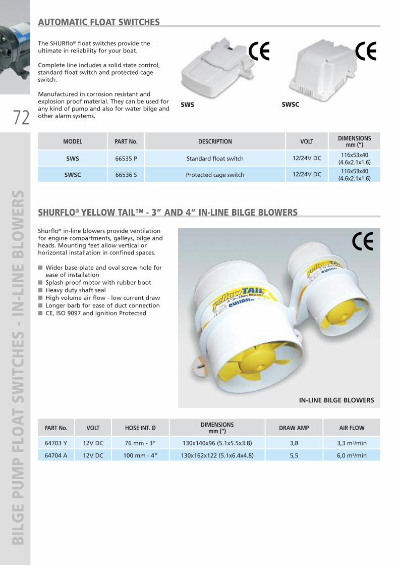
72
BILGE PUMP FLOAT SW
ITCHES - IN-LINE BLOWERS
VOLT
12/24V DC
MODEL
SWS
DESCRIPTION
Standard float switch
PART No.
66535 P
DIMENSIONSmm (“)
116x53x40(4.6x2.1x1.6)
12/24V DCSWSC Protected cage switch66536 S116x53x40(4.6x2.1x1.6)
AUTOMATIC FLOAT SWITCHES
The SHURflo® float switches provide theultimate in reliability for your boat.
Complete line includes a solid state control,standard float switch and protected cageswitch.
Manufactured in corrosion resistant andexplosion proof material. They can be used forany kind of pump and also for water bilge andother alarm systems.
SWSCSWS
SHURFLO® YELLOW TAIL™ - 3” AND 4” IN-LINE BILGE BLOWERS
Shurflo® in-line blowers provide ventilationfor engine compartments, galleys, bilge andheads. Mounting feet allow vertical orhorizontal installation in confined spaces.
� Wider base-plate and oval screw hole forease of installation
� Splash-proof motor with rubber boot� Heavy duty shaft seal� High volume air flow - low current draw� Longer barb for ease of duct connection� CE, ISO 9097 and Ignition Protected
IN-LINE BILGE BLOWERS
VOLT
12V DC
12V DC
HOSE INT. Ø
76 mm - 3”
100 mm - 4”
DIMENSIONSmm (“)
130x140x96 (5.1x5.5x3.8)
130x162x122 (5.1x6.4x4.8)
DRAW AMP
3,8
5,5
AIR FLOW
3,3 m3/min
6,0 m3/min
PART No.
64703 Y
64704 A
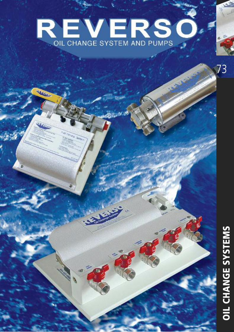
73
OIL CHANGE SYSTEM
S
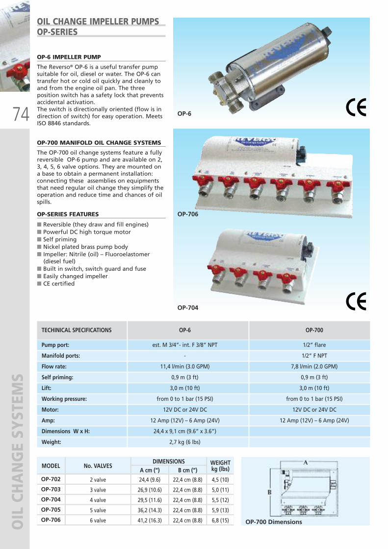
74
OIL CHANGE SYSTEM
S
OP-6 IMPELLER PUMP
The Reverso® OP-6 is a useful transfer pumpsuitable for oil, diesel or water. The OP-6 cantransfer hot or cold oil quickly and cleanly toand from the engine oil pan. The threeposition switch has a safety lock that preventsaccidental activation.The switch is directionally oriented (flow is indirection of switch) for easy operation. MeetsISO 8846 standards.
OP-700 MANIFOLD OIL CHANGE SYSTEMS
The OP-700 oil change systems feature a fullyreversible OP-6 pump and are available on 2,3, 4, 5, 6 valve options. They are mounted ona base to obtain a permanent installation:connecting these assemblies on equipmentsthat need regular oil change they simplify theoperation and reduce time and chances of oilspills.
OP-SERIES FEATURES
� Reversible (they draw and fill engines)� Powerful DC high torque motor � Self priming� Nickel plated brass pump body� Impeller: Nitrile (oil) – Fluoroelastomer (diesel fuel)� Built in switch, switch guard and fuse � Easily changed impeller � CE certified
OIL CHANGE IMPELLER PUMPSOP-SERIES
OP-6
OP-704
OP-706
OP-700 Dimensions
TECHINICAL SPECIFICATIONS OP-6 OP-700
Pump port: est. M 3/4”- int. F 3/8” NPT 1/2” flare
Manifold ports: - 1/2” F NPT
Flow rate: 11,4 l/min (3.0 GPM) 7,8 l/min (2.0 GPM)
Self priming: 0,9 m (3 ft) 0,9 m (3 ft)
Lift: 3,0 m (10 ft) 3,0 m (10 ft)
Working pressure: from 0 to 1 bar (15 PSI) from 0 to 1 bar (15 PSI)
Motor: 12V DC or 24V DC 12V DC or 24V DC
Amp: 12 Amp (12V) – 6 Amp (24V) 12 Amp (12V) – 6 Amp (24V)
Dimensions W x H: 24,4 x 9,1 cm (9.6” x 3.6”)
Weight: 2,7 kg (6 lbs)
MODEL No. VALVES WEIGHTkg (lbs)
DIMENSIONSA cm (“) B cm (“)
OP-702 2 valve 24,4 (9.6) 22,4 cm (8.8) 4,5 (10)
OP-703 3 valve 26,9 (10.6) 22,4 cm (8.8) 5,0 (11)
OP-704 4 valve 29,5 (11.6) 22,4 cm (8.8) 5,5 (12)
OP-705 5 valve 36,2 (14.3) 22,4 cm (8.8) 5,9 (13)
OP-706 6 valve 41,2 (16.3) 22,4 cm (8.8) 6,8 (15)
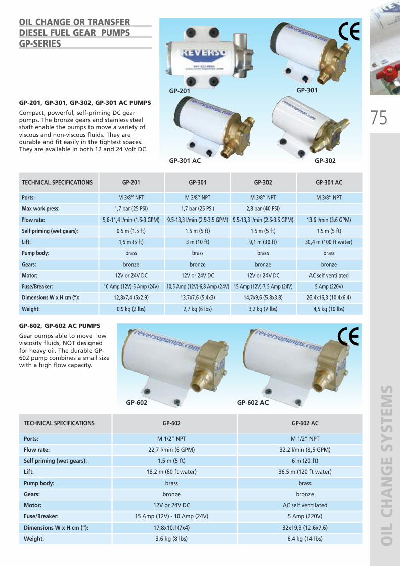
75
OIL CHANGE SYSTEM
S
OIL CHANGE OR TRANSFER DIESEL FUEL GEAR PUMPS GP-SERIES
GP-301
GP-301 AC
GP-602, GP-602 AC PUMPS
Gear pumps able to move lowviscosity fluids, NOT designedfor heavy oil. The durable GP-602 pump combines a small sizewith a high flow capacity.
GP-602 AC
TECHNICAL SPECIFICATIONS GP-201 GP-301 GP-302 GP-301 AC
Ports: M 3/8’’ NPT M 3/8’’ NPT M 3/8’’ NPT M 3/8’’ NPT
Max work press: 1,7 bar (25 PSI) 1,7 bar (25 PSI) 2,8 bar (40 PSI)
Flow rate: 5,6-11,4 l/min (1.5-3 GPM) 9.5-13,3 l/min (2.5-3.5 GPM) 9.5-13,3 l/min (2.5-3.5 GPM) 13.6 l/min (3.6 GPM)
Self priming (wet gears): 0.5 m (1.5 ft) 1.5 m (5 ft) 1.5 m (5 ft) 1.5 m (5 ft)
Lift: 1,5 m (5 ft) 3 m (10 ft) 9,1 m (30 ft) 30,4 m (100 ft water)
Pump body: brass brass brass brass
Gears: bronze bronze bronze bronze
Motor: 12V or 24V DC 12V or 24V DC 12V or 24V DC AC self ventilated
Fuse/Breaker: 10 Amp (12V)-5 Amp (24V) 10,5 Amp (12V)-6,8 Amp (24V) 15 Amp (12V)-7,5 Amp (24V) 5 Amp (220V)
Dimensions W x H cm (“): 12,8x7,4 (5x2.9) 13,7x7,6 (5.4x3) 14,7x9,6 (5.8x3.8) 26,4x16,3 (10.4x6.4)
Weight: 0,9 kg (2 lbs) 2,7 kg (6 lbs) 3,2 kg (7 lbs) 4,5 kg (10 lbs)
GP-201, GP-301, GP-302, GP-301 AC PUMPS
Compact, powerful, self-priming DC gearpumps. The bronze gears and stainless steelshaft enable the pumps to move a variety ofviscous and non-viscous fluids. They aredurable and fit easily in the tightest spaces.They are available in both 12 and 24 Volt DC.
TECHNICAL SPECIFICATIONS GP-602 GP-602 AC
Ports: M 1/2” NPT M 1/2” NPT
Flow rate: 22,7 l/min (6 GPM) 32,2 l/min (8,5 GPM)
Self priming (wet gears): 1,5 m (5 ft) 6 m (20 ft)
Lift: 18,2 m (60 ft water) 36,5 m (120 ft water)
Pump body: brass brass
Gears: bronze bronze
Motor: 12V or 24V DC AC self ventilated
Fuse/Breaker: 15 Amp (12V) - 10 Amp (24V) 5 Amp (220V)
Dimensions W x H cm (“): 17,8x10,1(7x4) 32x19,3 (12.6x7.6)
Weight: 3,6 kg (8 lbs) 6,4 kg (14 lbs)
GP-602
GP-302
GP-201
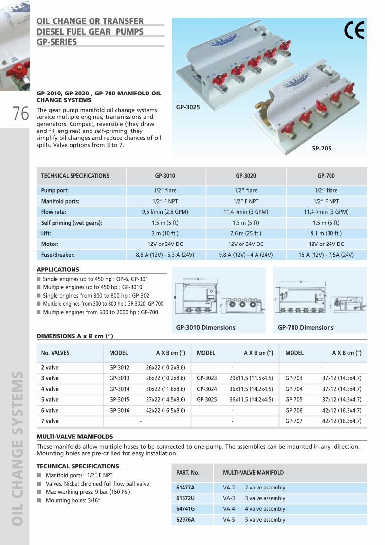
76
OIL CHANGE SYSTEM
S
GP-3010, GP-3020 , GP-700 MANIFOLD OILCHANGE SYSTEMS
The gear pump manifold oil change systemsservice multiple engines, transmissions andgenerators. Compact, reversible (they drawand fill engines) and self-priming, theysimplify oil changes and reduce chances of oilspills. Valve options from 3 to 7.
APPLICATIONS
� Single engines up to 450 hp : OP-6, GP-301� Multiple engines up to 450 hp : GP-3010� Single engines from 300 to 800 hp : GP-302� Multiple engines from 300 to 800 hp : GP-3020, GP-700� Multiple engines from 600 to 2000 hp : GP-700
MULTI-VALVE MANIFOLDS
These manifolds allow multiple hoses to be connected to one pump. The assemblies can be mounted in any direction.Mounting holes are pre-drilled for easy installation.
TECHNICAL SPECIFICATIONS
� Manifold ports: 1/2” F NPT� Valves: Nickel chromed full flow ball valve� Max working press: 9 bar (150 PSI) � Mounting holes: 3/16”
OIL CHANGE OR TRANSFER DIESEL FUEL GEAR PUMPS GP-SERIES
GP-3025
GP-705
PART. No. MULTI-VALVE MANIFOLD
61477A VA-2 2 valve assembly
61572U VA-3 3 valve assembly
64741G VA-4 4 valve assembly
62976A VA-5 5 valve assembly
TECHNICAL SPECIFICATIONS GP-3010 GP-3020 GP-700
Pump port: 1/2” flare 1/2” flare 1/2” flare
Manifold ports: 1/2” F NPT 1/2” F NPT 1/2” F NPT
Flow rate: 9,5 l/min (2.5 GPM) 11,4 l/min (3 GPM) 11,4 l/min (3 GPM)
Self priming (wet gears): 1,5 m (5 ft) 1,5 m (5 ft) 1,5 m (5 ft)
Lift: 3 m (10 ft ) 7,6 m (25 ft ) 9,1 m (30 ft )
Motor: 12V or 24V DC 12V or 24V DC 12V or 24V DC
Fuse/Breaker: 8,8 A (12V) - 5,3 A (24V) 9,8 A (12V) - 4 A (24V) 15 A (12V) - 7,5A (24V)
GP-3010 Dimensions GP-700 Dimensions
No. VALVES MODEL A X B cm (“) MODEL A X B cm (“) MODEL A X B cm (“)
2 valve GP-3012 26x22 (10.2x8.6) - -
3 valve GP-3013 26x22 (10.2x8.6) GP-3023 29x11,5 (11.5x4.5) GP-703 37x12 (14.5x4.7)
4 valve GP-3014 30x22 (11.8x8.6) GP-3024 36x11,5 (14.2x4.5) GP-704 37x12 (14.5x4.7)
5 valve GP-3015 37x22 (14.5x8.6) GP-3025 36x11,5 (14.2x4.5) GP-705 37x12 (14.5x4.7)
6 valve GP-3016 42x22 (16.5x8.6) - GP-706 42x12 (16.5x4.7)
7 valve - - GP-707 42x12 (16.5x4.7)
DIMENSIONS A x B cm (“)
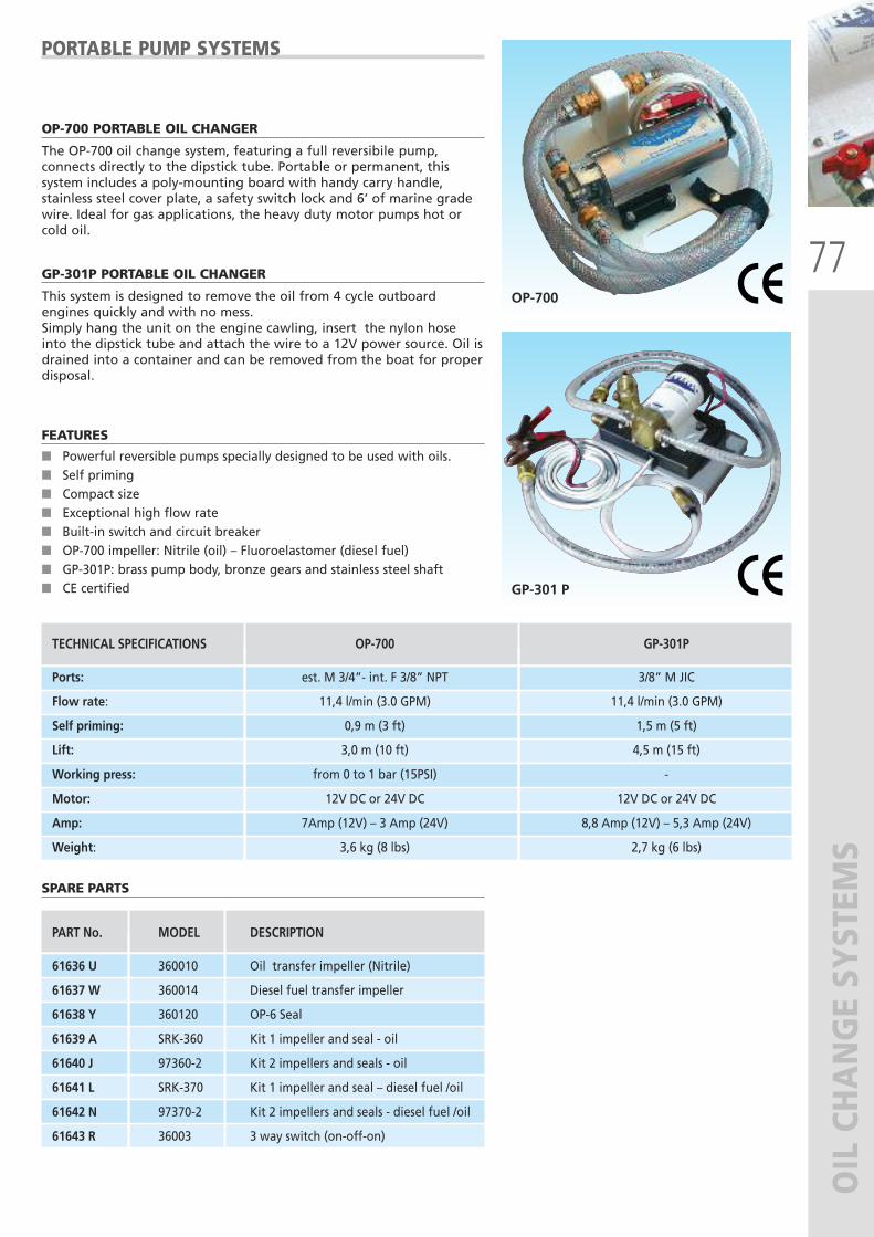
77
OIL CHANGE SYSTEM
S
OP-700 PORTABLE OIL CHANGER
The OP-700 oil change system, featuring a full reversibile pump,connects directly to the dipstick tube. Portable or permanent, thissystem includes a poly-mounting board with handy carry handle,stainless steel cover plate, a safety switch lock and 6’ of marine gradewire. Ideal for gas applications, the heavy duty motor pumps hot orcold oil.
GP-301P PORTABLE OIL CHANGER
This system is designed to remove the oil from 4 cycle outboardengines quickly and with no mess.Simply hang the unit on the engine cawling, insert the nylon hoseinto the dipstick tube and attach the wire to a 12V power source. Oil isdrained into a container and can be removed from the boat for properdisposal.
FEATURES
� Powerful reversible pumps specially designed to be used with oils.� Self priming� Compact size� Exceptional high flow rate� Built-in switch and circuit breaker � OP-700 impeller: Nitrile (oil) – Fluoroelastomer (diesel fuel)� GP-301P: brass pump body, bronze gears and stainless steel shaft� CE certified
PORTABLE PUMP SYSTEMS
OP-700
GP-301 P
PART No. MODEL DESCRIPTION
61636 U 360010 Oil transfer impeller (Nitrile)
61637 W 360014 Diesel fuel transfer impeller
61638 Y 360120 OP-6 Seal
61639 A SRK-360 Kit 1 impeller and seal - oil
61640 J 97360-2 Kit 2 impellers and seals - oil
61641 L SRK-370 Kit 1 impeller and seal – diesel fuel /oil
61642 N 97370-2 Kit 2 impellers and seals - diesel fuel /oil
61643 R 36003 3 way switch (on-off-on)
TECHNICAL SPECIFICATIONS OP-700 GP-301P
Ports: est. M 3/4”- int. F 3/8” NPT 3/8” M JIC
Flow rate: 11,4 l/min (3.0 GPM) 11,4 l/min (3.0 GPM)
Self priming: 0,9 m (3 ft) 1,5 m (5 ft)
Lift: 3,0 m (10 ft) 4,5 m (15 ft)
Working press: from 0 to 1 bar (15PSI) -
Motor: 12V DC or 24V DC 12V DC or 24V DC
Amp: 7Amp (12V) – 3 Amp (24V) 8,8 Amp (12V) – 5,3 Amp (24V)
Weight: 3,6 kg (8 lbs) 2,7 kg (6 lbs)
SPARE PARTS
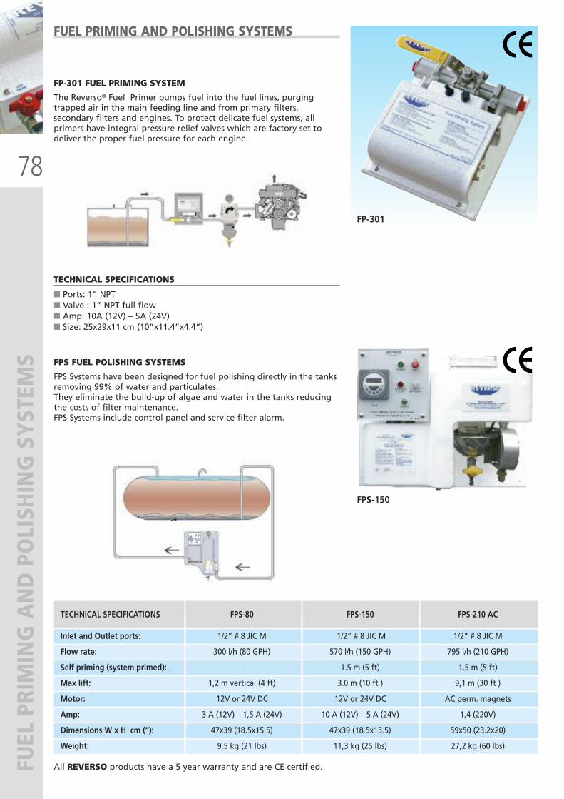
78
FUEL PRIMING AND POLISHING SYSTEM
S
FP-301 FUEL PRIMING SYSTEM
The Reverso® Fuel Primer pumps fuel into the fuel lines, purgingtrapped air in the main feeding line and from primary filters,secondary filters and engines. To protect delicate fuel systems, allprimers have integral pressure relief valves which are factory set todeliver the proper fuel pressure for each engine.
TECHNICAL SPECIFICATIONS
� Ports: 1” NPT � Valve : 1” NPT full flow� Amp: 10A (12V) – 5A (24V)� Size: 25x29x11 cm (10”x11.4”x4.4”)
FUEL PRIMING AND POLISHING SYSTEMS
FP-301
FPS FUEL POLISHING SYSTEMS
FPS Systems have been designed for fuel polishing directly in the tanksremoving 99% of water and particulates.They eliminate the build-up of algae and water in the tanks reducingthe costs of filter maintenance.FPS Systems include control panel and service filter alarm.
FPS-150
TECHNICAL SPECIFICATIONS FPS-80 FPS-150 FPS-210 AC
Inlet and Outlet ports: 1/2” # 8 JIC M 1/2” # 8 JIC M 1/2” # 8 JIC M
Flow rate: 300 l/h (80 GPH) 570 l/h (150 GPH) 795 l/h (210 GPH)
Self priming (system primed): - 1.5 m (5 ft) 1.5 m (5 ft)
Max lift: 1,2 m vertical (4 ft) 3.0 m (10 ft ) 9,1 m (30 ft )
Motor: 12V or 24V DC 12V or 24V DC AC perm. magnets
Amp: 3 A (12V) – 1,5 A (24V) 10 A (12V) – 5 A (24V) 1,4 (220V)
Dimensions W x H cm (“): 47x39 (18.5x15.5) 47x39 (18.5x15.5) 59x50 (23.2x20)
Weight: 9,5 kg (21 lbs) 11,3 kg (25 lbs) 27,2 kg (60 lbs)
All REVERSO products have a 5 year warranty and are CE certified.

79
MARINE PUMPS AND BLOWERS
A world of marine equipment
®®
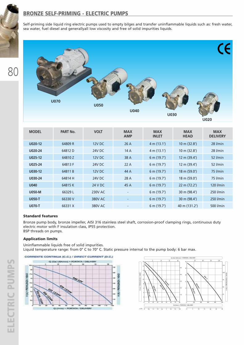
80
ELECTRIC PUMPS
MODEL PART No. VOLT MAX MAX MAX MAX AMP INLET HEAD DELIVERY
U020-12 64809 R 12V DC 26 A 4 m (13.1’) 10 m (32.8’) 28 l/min
U020-24 64812 D 24V DC 14 A 4 m (13.1’) 10 m (32.8’) 28 l/min
U025-12 64810 Z 12V DC 38 A 6 m (19.7’) 12 m (39.4’) 52 l/min
U025-24 64813 F 24V DC 22 A 6 m (19.7’) 12 m (39.4’) 52 l/min
U030-12 64811 B 12V DC 44 A 6 m (19.7’) 18 m (59.0’) 75 l/min
U030-24 64814 H 24V DC 28 A 6 m (19.7’) 18 m (59.0’) 75 l/min
U040 64815 K 24 V DC 45 A 6 m (19.7’) 22 m (72.2’) 120 l/min
U050-M 66329 L 230V AC - 6 m (19.7’) 30 m (98.4’) 250 l/min
U050-T 66330 V 380V AC - 6 m (19.7’) 30 m (98.4’) 250 l/min
U070-T 66331 X 380V AC - 6 m (19.7’) 40 m (131.2’) 500 l/min
BRONZE SELF-PRIMING - ELECTRIC PUMPS
U070U050
U040U030
U020
Self-priming side liquid ring electric pumps used to empty bilges and transfer uninflammable liquids such as: fresh water,sea water, fuel diesel and generallyall low viscosity and free of solid impurities liquids.
Standard features
Bronze pump body, bronze impeller, AISI 316 stainless steel shaft, corrosion-proof clamping rings, continuous dutyelectric motor with F insulation class, IP55 protection.BSP threads on pumps.
Application limits
Uninflammable liquids free of solid impurities.Liquid temperature range: from 0° C to 70° C. Static pressure internal to the pump body: 6 bar max.
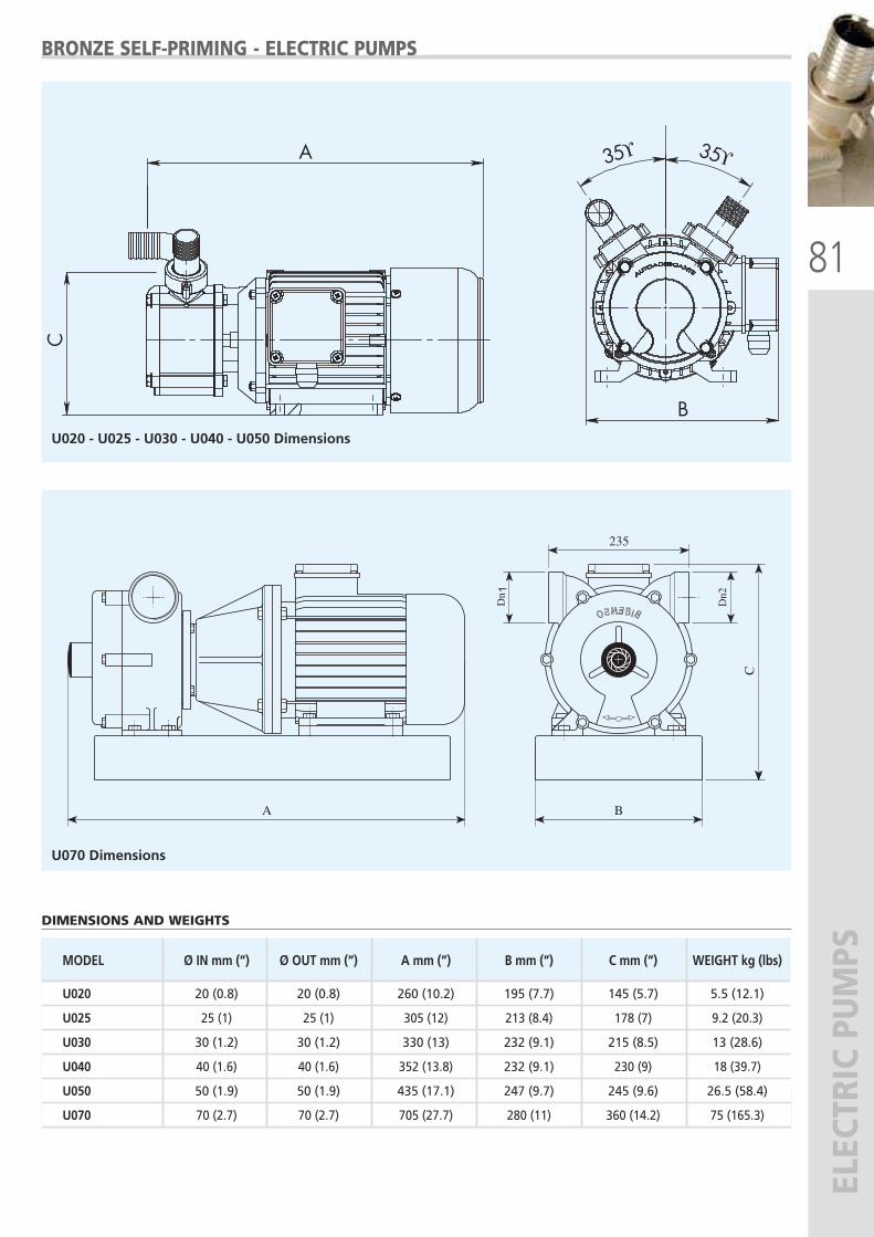
81
ELECTRIC PUMPS
35ϒ35ϒ
B
A
C
Dn 1
235
BA
C
Dn2
BRONZE SELF-PRIMING - ELECTRIC PUMPS
U020 - U025 - U030 - U040 - U050 Dimensions
U070 Dimensions
MODEL Ø IN mm (“) Ø OUT mm (“) A mm (“) B mm (“) C mm (“) WEIGHT kg (lbs)
U020 20 (0.8) 20 (0.8) 260 (10.2) 195 (7.7) 145 (5.7) 5.5 (12.1)
U025 25 (1) 25 (1) 305 (12) 213 (8.4) 178 (7) 9.2 (20.3)
U030 30 (1.2) 30 (1.2) 330 (13) 232 (9.1) 215 (8.5) 13 (28.6)
U040 40 (1.6) 40 (1.6) 352 (13.8) 232 (9.1) 230 (9) 18 (39.7)
U050 50 (1.9) 50 (1.9) 435 (17.1) 247 (9.7) 245 (9.6) 26.5 (58.4)
U070 70 (2.7) 70 (2.7) 705 (27.7) 280 (11) 360 (14.2) 75 (165.3)
DIMENSIONS AND WEIGHTS
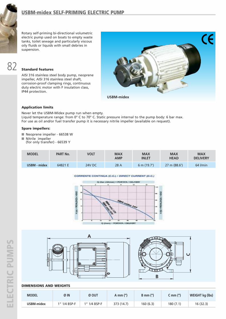
82
ELECTRIC PUMPS
A
B
C
DIMENSIONS AND WEIGHTS
MODEL Ø IN Ø OUT A mm (“) B mm (“) C mm (“) WEIGHT kg (lbs)
USBM-midex 1” 1/4 BSP-F 1” 1/4 BSP-F 373 (14.7) 160 (6.3) 180 (7.1) 16 (32.3)
USBM-midex
USBM-midex SELF-PRIMING ELECTRIC PUMP
Rotary self-priming bi-directional volumetricelectric pump used on boats to empty wastetanks, toilet sewage and particularly viscousoily fluids or liquids with small debries insuspension.
Standard features
AISI 316 stainless steel body pump, neopreneimpeller, AISI 316 stainless steel shaft,corrosion-proof clamping rings, continuousduty electric motor with F insulation class,IP44 protection.
Application limits
Never let the USBM-Midex pump run when empty. Liquid temperature range: from 0° C to 70° C. Static pressure internal to the pump body: 6 bar max.For use as oil and/or fuel transfer pump it is necessary nitrile impeller (available on request).
Spare impellers:
� Neoprene impeller - 66538 W� Nitrile impeller(for only transfer) - 66539 Y
MODEL PART No. VOLT MAX MAX MAX MAX AMP INLET HEAD DELIVERY
USBM - midex 64821 E 24V DC 28 A 6 m (19.7’) 27 m (88.6’) 64 l/min
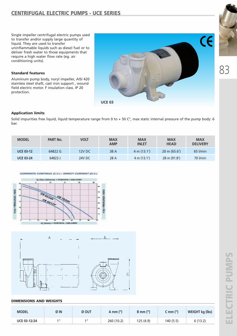
83
ELECTRIC PUMPS
MODEL PART No. VOLT MAX MAX MAX MAX AMP INLET HEAD DELIVERY
UCE 03-12 64822 G 12V DC 38 A 4 m (13.1’) 20 m (65.6’) 65 l/min
UCE 03-24 64823 J 24V DC 28 A 4 m (13.1’) 28 m (91.8’) 70 l/min
UCE 03
CENTRIFUGAL ELECTRIC PUMPS - UCE SERIES
Single impeller centrifugal electric pumps usedto transfer and/or supply large quantity ofliquid. They are used to transferuninflammable liquids such as diesel fuel or todeliver fresh water to those equipments thatrequire a high water flow rate (eg. airconditioning units).
Standard features
Aluminum pump body, noryl impeller, AISI 420stainless steel shaft, cast iron support , woundfield electric motor. F insulation class. IP 20protection.
Application limits
Solid impurities free liquid, liquid temperature range from 0 to + 50 C°, max static internal pressure of the pump body: 6bar.
DIMENSIONS AND WEIGHTS
MODEL Ø IN Ø OUT A mm (“) B mm (“) C mm (“) WEIGHT kg (lbs)
UCE 03-12/24 1” 1” 260 (10.2) 125 (4.9) 140 (5.5) 6 (13.2)
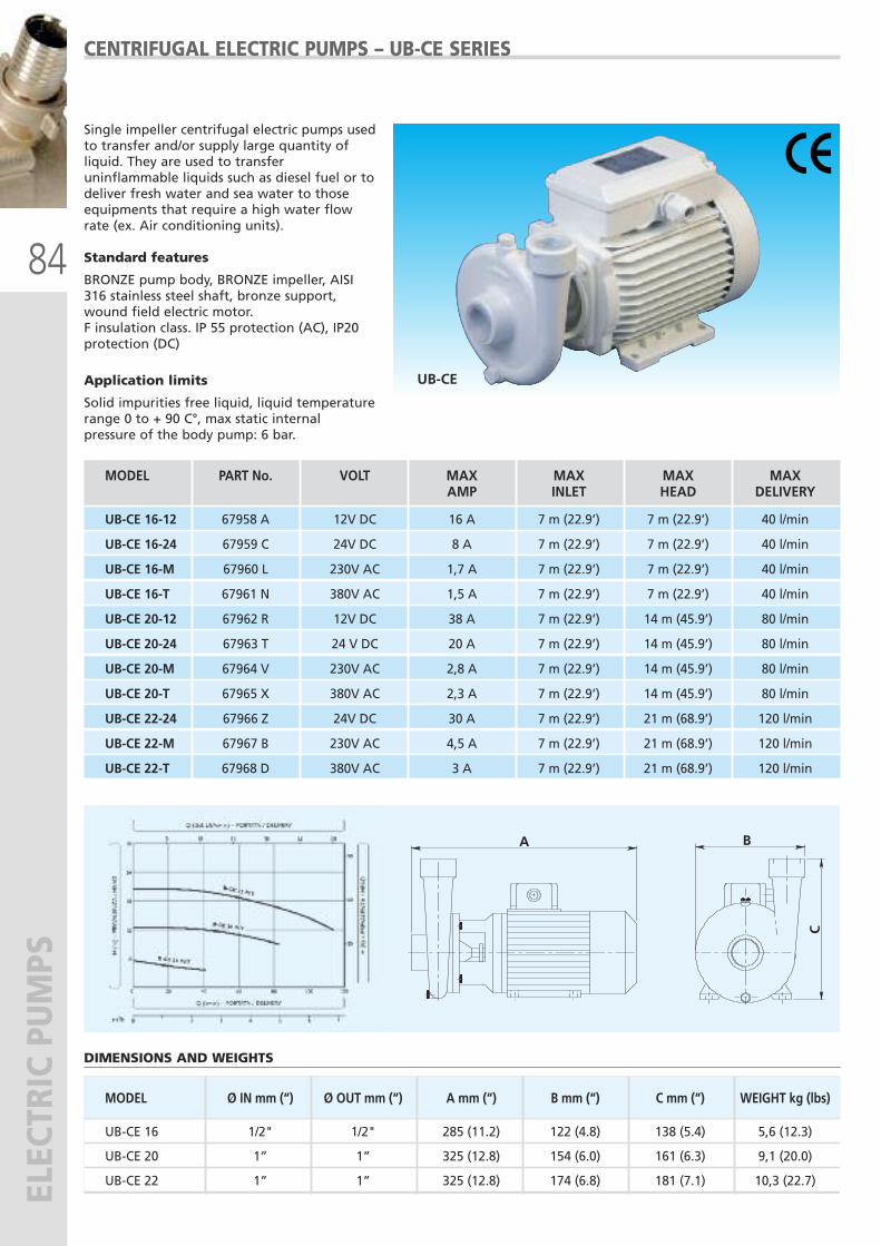
84
ELECTRIC PUMPS
MODEL Ø IN mm (“) Ø OUT mm (“) A mm (“) B mm (“) C mm (“) WEIGHT kg (lbs)
UB-CE 16 1/2" 1/2" 285 (11.2) 122 (4.8) 138 (5.4) 5,6 (12.3)
UB-CE 20 1” 1” 325 (12.8) 154 (6.0) 161 (6.3) 9,1 (20.0)
UB-CE 22 1” 1” 325 (12.8) 174 (6.8) 181 (7.1) 10,3 (22.7)
CENTRIFUGAL ELECTRIC PUMPS – UB-CE SERIES
Single impeller centrifugal electric pumps usedto transfer and/or supply large quantity ofliquid. They are used to transferuninflammable liquids such as diesel fuel or todeliver fresh water and sea water to thoseequipments that require a high water flowrate (ex. Air conditioning units).
Standard features
BRONZE pump body, BRONZE impeller, AISI316 stainless steel shaft, bronze support,wound field electric motor.F insulation class. IP 55 protection (AC), IP20protection (DC)
Application limits
Solid impurities free liquid, liquid temperaturerange 0 to + 90 C°, max static internalpressure of the body pump: 6 bar.
UB-CE
DIMENSIONS AND WEIGHTS
A B
C
MODEL PART No. VOLT MAX MAX MAX MAX AMP INLET HEAD DELIVERY
UB-CE 16-12 67958 A 12V DC 16 A 7 m (22.9’) 7 m (22.9’) 40 l/min
UB-CE 16-24 67959 C 24V DC 8 A 7 m (22.9’) 7 m (22.9’) 40 l/min
UB-CE 16-M 67960 L 230V AC 1,7 A 7 m (22.9’) 7 m (22.9’) 40 l/min
UB-CE 16-T 67961 N 380V AC 1,5 A 7 m (22.9’) 7 m (22.9’) 40 l/min
UB-CE 20-12 67962 R 12V DC 38 A 7 m (22.9’) 14 m (45.9’) 80 l/min
UB-CE 20-24 67963 T 24 V DC 20 A 7 m (22.9’) 14 m (45.9’) 80 l/min
UB-CE 20-M 67964 V 230V AC 2,8 A 7 m (22.9’) 14 m (45.9’) 80 l/min
UB-CE 20-T 67965 X 380V AC 2,3 A 7 m (22.9’) 14 m (45.9’) 80 l/min
UB-CE 22-24 67966 Z 24V DC 30 A 7 m (22.9’) 21 m (68.9’) 120 l/min
UB-CE 22-M 67967 B 230V AC 4,5 A 7 m (22.9’) 21 m (68.9’) 120 l/min
UB-CE 22-T 67968 D 380V AC 3 A 7 m (22.9’) 21 m (68.9’) 120 l/min
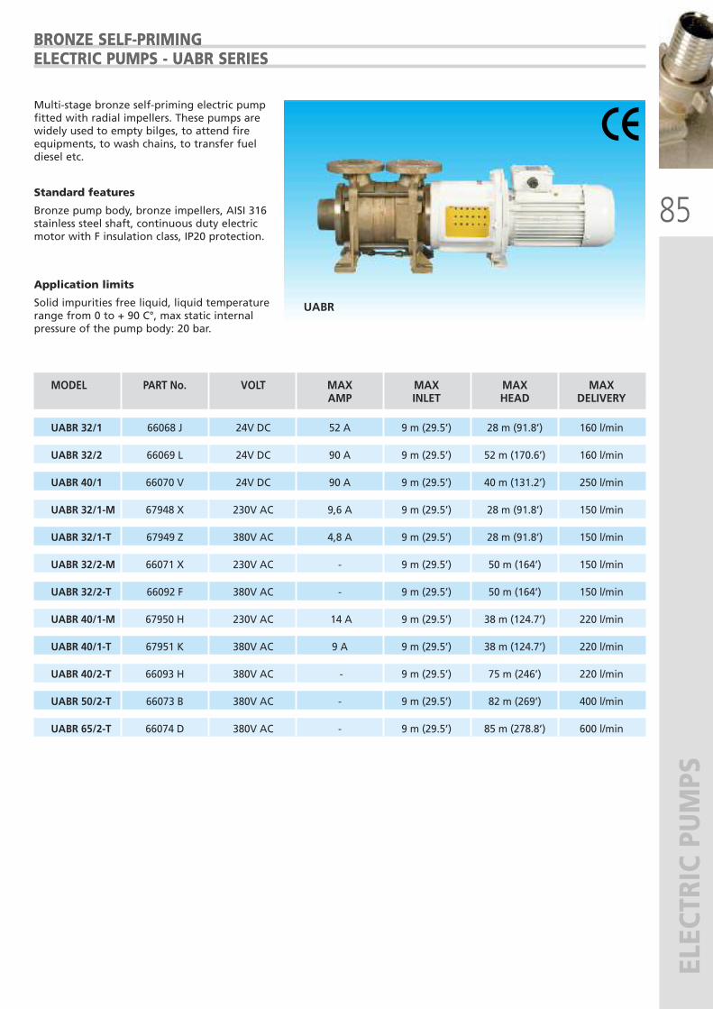
85
ELECTRIC PUMPS
MODEL PART No. VOLT MAX MAX MAX MAX AMP INLET HEAD DELIVERY
UABR 32/1 66068 J 24V DC 52 A 9 m (29.5’) 28 m (91.8’) 160 l/min
UABR 32/2 66069 L 24V DC 90 A 9 m (29.5’) 52 m (170.6’) 160 l/min
UABR 40/1 66070 V 24V DC 90 A 9 m (29.5’) 40 m (131.2’) 250 l/min
UABR 32/1-M 67948 X 230V AC 9,6 A 9 m (29.5’) 28 m (91.8’) 150 l/min
UABR 32/1-T 67949 Z 380V AC 4,8 A 9 m (29.5’) 28 m (91.8’) 150 l/min
UABR 32/2-M 66071 X 230V AC - 9 m (29.5’) 50 m (164’) 150 l/min
UABR 32/2-T 66092 F 380V AC - 9 m (29.5’) 50 m (164’) 150 l/min
UABR 40/1-M 67950 H 230V AC 14 A 9 m (29.5’) 38 m (124.7’) 220 l/min
UABR 40/1-T 67951 K 380V AC 9 A 9 m (29.5’) 38 m (124.7’) 220 l/min
UABR 40/2-T 66093 H 380V AC - 9 m (29.5’) 75 m (246’) 220 l/min
UABR 50/2-T 66073 B 380V AC - 9 m (29.5’) 82 m (269’) 400 l/min
UABR 65/2-T 66074 D 380V AC - 9 m (29.5’) 85 m (278.8’) 600 l/min
BRONZE SELF-PRIMING ELECTRIC PUMPS - UABR SERIES
Multi-stage bronze self-priming electric pumpfitted with radial impellers. These pumps arewidely used to empty bilges, to attend fireequipments, to wash chains, to transfer fueldiesel etc.
Standard features
Bronze pump body, bronze impellers, AISI 316stainless steel shaft, continuous duty electricmotor with F insulation class, IP20 protection.
Application limits
Solid impurities free liquid, liquid temperaturerange from 0 to + 90 C°, max static internalpressure of the pump body: 20 bar.
UABR
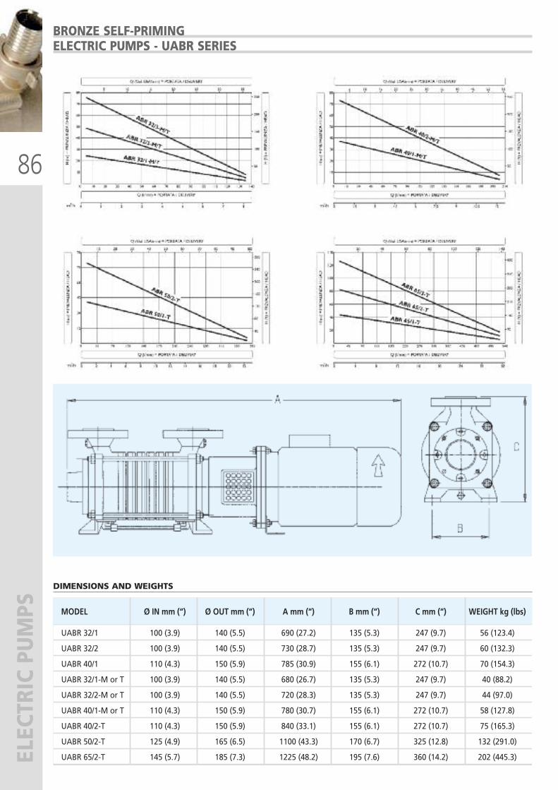
86
ELECTRIC PUMPS
MODEL Ø IN mm (“) Ø OUT mm (“) A mm (“) B mm (“) C mm (“) WEIGHT kg (lbs)
UABR 32/1 100 (3.9) 140 (5.5) 690 (27.2) 135 (5.3) 247 (9.7) 56 (123.4)
UABR 32/2 100 (3.9) 140 (5.5) 730 (28.7) 135 (5.3) 247 (9.7) 60 (132.3)
UABR 40/1 110 (4.3) 150 (5.9) 785 (30.9) 155 (6.1) 272 (10.7) 70 (154.3)
UABR 32/1-M or T 100 (3.9) 140 (5.5) 680 (26.7) 135 (5.3) 247 (9.7) 40 (88.2)
UABR 32/2-M or T 100 (3.9) 140 (5.5) 720 (28.3) 135 (5.3) 247 (9.7) 44 (97.0)
UABR 40/1-M or T 110 (4.3) 150 (5.9) 780 (30.7) 155 (6.1) 272 (10.7) 58 (127.8)
UABR 40/2-T 110 (4.3) 150 (5.9) 840 (33.1) 155 (6.1) 272 (10.7) 75 (165.3)
UABR 50/2-T 125 (4.9) 165 (6.5) 1100 (43.3) 170 (6.7) 325 (12.8) 132 (291.0)
UABR 65/2-T 145 (5.7) 185 (7.3) 1225 (48.2) 195 (7.6) 360 (14.2) 202 (445.3)
DIMENSIONS AND WEIGHTS
BRONZE SELF-PRIMING ELECTRIC PUMPS - UABR SERIES
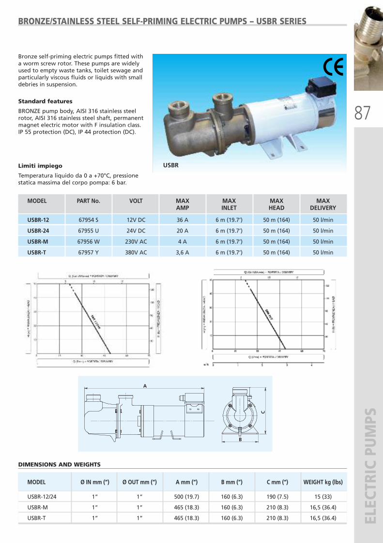
87
ELECTRIC PUMPS
MODEL Ø IN mm (“) Ø OUT mm (“) A mm (“) B mm (“) C mm (“) WEIGHT kg (lbs)
USBR-12/24 1” 1” 500 (19.7) 160 (6.3) 190 (7.5) 15 (33)
USBR-M 1” 1” 465 (18.3) 160 (6.3) 210 (8.3) 16,5 (36.4)
USBR-T 1” 1” 465 (18.3) 160 (6.3) 210 (8.3) 16,5 (36.4)
BRONZE/STAINLESS STEEL SELF-PRIMING ELECTRIC PUMPS – USBR SERIES
Bronze self-priming electric pumps fitted witha worm screw rotor. These pumps are widelyused to empty waste tanks, toilet sewage andparticularly viscous fluids or liquids with smalldebries in suspension.
Standard features
BRONZE pump body, AISI 316 stainless steelrotor, AISI 316 stainless steel shaft, permanentmagnet electric motor with F insulation class.IP 55 protection (DC), IP 44 protection (DC).
Limiti impiego
Temperatura liquido da 0 a +70°C, pressionestatica massima del corpo pompa: 6 bar.
USBR
DIMENSIONS AND WEIGHTS
A
B
C
MODEL PART No. VOLT MAX MAX MAX MAX AMP INLET HEAD DELIVERY
USBR-12 67954 S 12V DC 36 A 6 m (19.7’) 50 m (164) 50 l/min
USBR-24 67955 U 24V DC 20 A 6 m (19.7’) 50 m (164) 50 l/min
USBR-M 67956 W 230V AC 4 A 6 m (19.7’) 50 m (164) 50 l/min
USBR-T 67957 Y 380V AC 3,6 A 6 m (19.7’) 50 m (164) 50 l/min
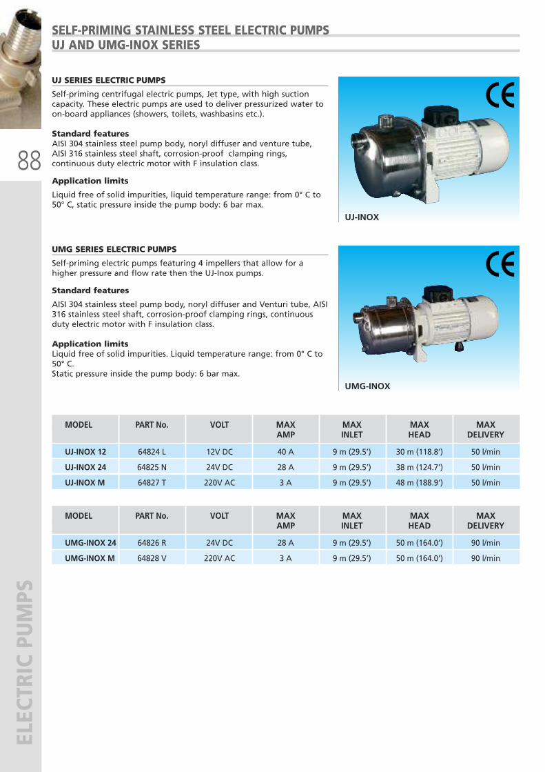
88
ELECTRIC PUMPS
UJ-INOX
SELF-PRIMING STAINLESS STEEL ELECTRIC PUMPSUJ AND UMG-INOX SERIES
UJ SERIES ELECTRIC PUMPS
Self-priming centrifugal electric pumps, Jet type, with high suctioncapacity. These electric pumps are used to deliver pressurized water toon-board appliances (showers, toilets, washbasins etc.).
Standard featuresAISI 304 stainless steel pump body, noryl diffuser and venture tube,AISI 316 stainless steel shaft, corrosion-proof clamping rings,continuous duty electric motor with F insulation class.
Application limits
Liquid free of solid impurities, liquid temperature range: from 0° C to50° C, static pressure inside the pump body: 6 bar max.
UMG-INOX
UMG SERIES ELECTRIC PUMPS
Self-priming electric pumps featuring 4 impellers that allow for ahigher pressure and flow rate then the UJ-Inox pumps.
Standard features
AISI 304 stainless steel pump body, noryl diffuser and Venturi tube, AISI316 stainless steel shaft, corrosion-proof clamping rings, continuousduty electric motor with F insulation class.
Application limits Liquid free of solid impurities. Liquid temperature range: from 0° C to50° C.Static pressure inside the pump body: 6 bar max.
MODEL PART No. VOLT MAX MAX MAX MAX AMP INLET HEAD DELIVERY
UJ-INOX 12 64824 L 12V DC 40 A 9 m (29.5’) 30 m (118.8’) 50 l/min
UJ-INOX 24 64825 N 24V DC 28 A 9 m (29.5’) 38 m (124.7’) 50 l/min
UJ-INOX M 64827 T 220V AC 3 A 9 m (29.5’) 48 m (188.9’) 50 l/min
MODEL PART No. VOLT MAX MAX MAX MAX AMP INLET HEAD DELIVERY
UMG-INOX 24 64826 R 24V DC 28 A 9 m (29.5’) 50 m (164.0’) 90 l/min
UMG-INOX M 64828 V 220V AC 3 A 9 m (29.5’) 50 m (164.0’) 90 l/min
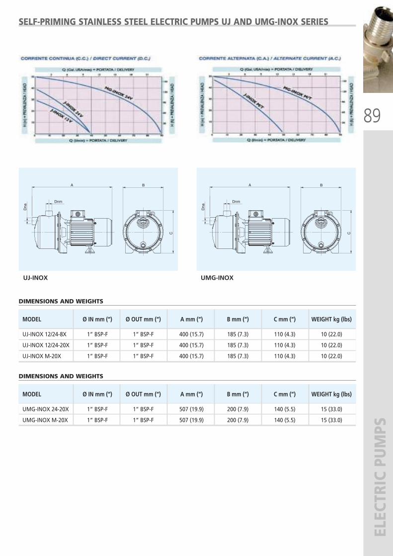
89
ELECTRIC PUMPS
SELF-PRIMING STAINLESS STEEL ELECTRIC PUMPS UJ AND UMG-INOX SERIES
B
C
Dnm
Dna
A B
C
DnmD
na
A
UJ-INOX UMG-INOX
MODEL Ø IN mm (“) Ø OUT mm (“) A mm (“) B mm (“) C mm (“) WEIGHT kg (lbs)
UJ-INOX 12/24-8X 1” BSP-F 1” BSP-F 400 (15.7) 185 (7.3) 110 (4.3) 10 (22.0)
UJ-INOX 12/24-20X 1” BSP-F 1” BSP-F 400 (15.7) 185 (7.3) 110 (4.3) 10 (22.0)
UJ-INOX M-20X 1” BSP-F 1” BSP-F 400 (15.7) 185 (7.3) 110 (4.3) 10 (22.0)
DIMENSIONS AND WEIGHTS
DIMENSIONS AND WEIGHTS
MODEL Ø IN mm (“) Ø OUT mm (“) A mm (“) B mm (“) C mm (“) WEIGHT kg (lbs)
UMG-INOX 24-20X 1” BSP-F 1” BSP-F 507 (19.9) 200 (7.9) 140 (5.5) 15 (33.0)
UMG-INOX M-20X 1” BSP-F 1” BSP-F 507 (19.9) 200 (7.9) 140 (5.5) 15 (33.0)
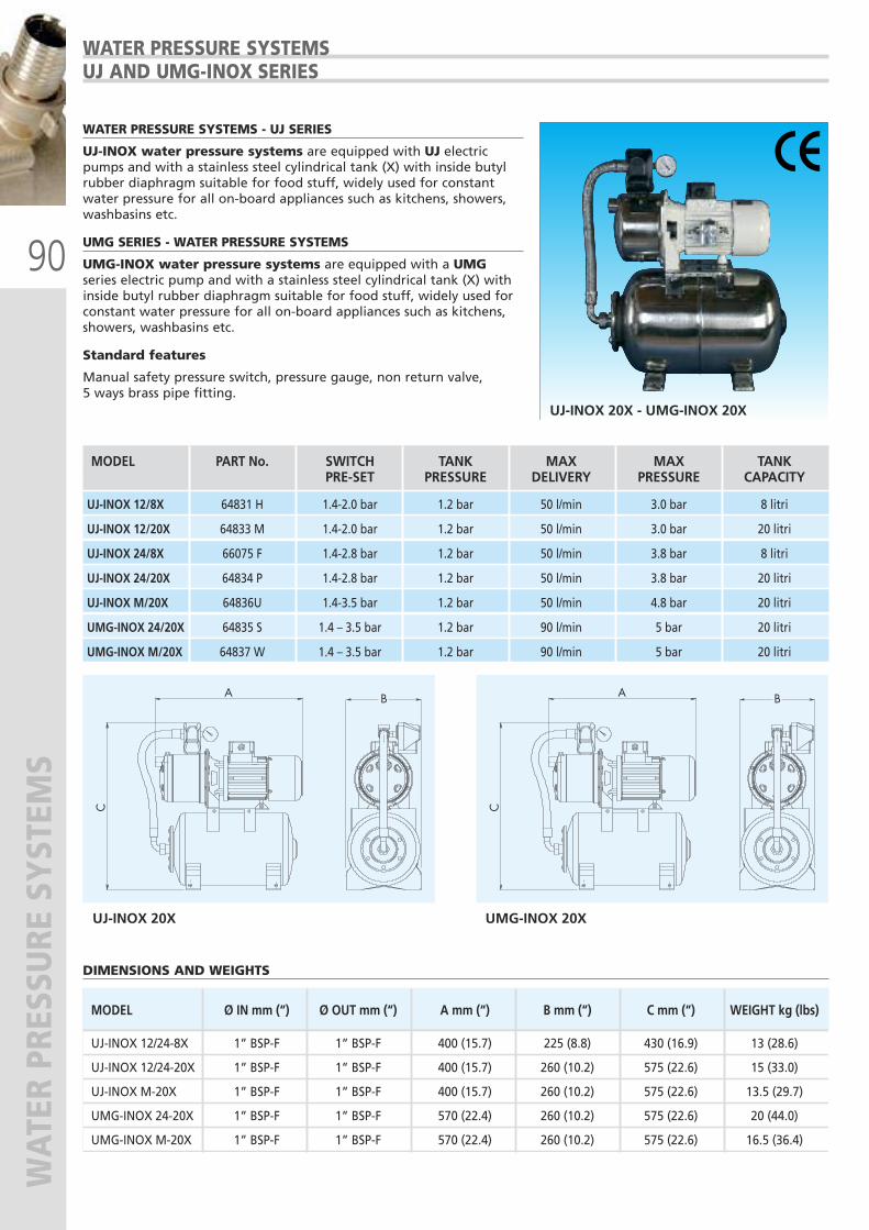
90
WATER PRESSURE SYSTEM
SWATER PRESSURE SYSTEMSUJ AND UMG-INOX SERIES
UJ-INOX 20X - UMG-INOX 20X
WATER PRESSURE SYSTEMS - UJ SERIES
UJ-INOX water pressure systems are equipped with UJ electricpumps and with a stainless steel cylindrical tank (X) with inside butylrubber diaphragm suitable for food stuff, widely used for constantwater pressure for all on-board appliances such as kitchens, showers,washbasins etc.
UMG SERIES - WATER PRESSURE SYSTEMS
UMG-INOX water pressure systems are equipped with a UMGseries electric pump and with a stainless steel cylindrical tank (X) withinside butyl rubber diaphragm suitable for food stuff, widely used forconstant water pressure for all on-board appliances such as kitchens,showers, washbasins etc.
Standard features
Manual safety pressure switch, pressure gauge, non return valve, 5 ways brass pipe fitting.
MODEL PART No. SWITCH TANK MAX MAX TANK PRE-SET PRESSURE DELIVERY PRESSURE CAPACITY
UJ-INOX 12/8X 64831 H 1.4-2.0 bar 1.2 bar 50 l/min 3.0 bar 8 litri
UJ-INOX 12/20X 64833 M 1.4-2.0 bar 1.2 bar 50 l/min 3.0 bar 20 litri
UJ-INOX 24/8X 66075 F 1.4-2.8 bar 1.2 bar 50 l/min 3.8 bar 8 litri
UJ-INOX 24/20X 64834 P 1.4-2.8 bar 1.2 bar 50 l/min 3.8 bar 20 litri
UJ-INOX M/20X 64836U 1.4-3.5 bar 1.2 bar 50 l/min 4.8 bar 20 litri
UMG-INOX 24/20X 64835 S 1.4 – 3.5 bar 1.2 bar 90 l/min 5 bar 20 litri
UMG-INOX M/20X 64837 W 1.4 – 3.5 bar 1.2 bar 90 l/min 5 bar 20 litri
UJ-INOX 20X UMG-INOX 20X
DIMENSIONS AND WEIGHTS
MODEL Ø IN mm (“) Ø OUT mm (“) A mm (“) B mm (“) C mm (“) WEIGHT kg (lbs)
UJ-INOX 12/24-8X 1” BSP-F 1” BSP-F 400 (15.7) 225 (8.8) 430 (16.9) 13 (28.6)
UJ-INOX 12/24-20X 1” BSP-F 1” BSP-F 400 (15.7) 260 (10.2) 575 (22.6) 15 (33.0)
UJ-INOX M-20X 1” BSP-F 1” BSP-F 400 (15.7) 260 (10.2) 575 (22.6) 13.5 (29.7)
UMG-INOX 24-20X 1” BSP-F 1” BSP-F 570 (22.4) 260 (10.2) 575 (22.6) 20 (44.0)
UMG-INOX M-20X 1” BSP-F 1” BSP-F 570 (22.4) 260 (10.2) 575 (22.6) 16.5 (36.4)
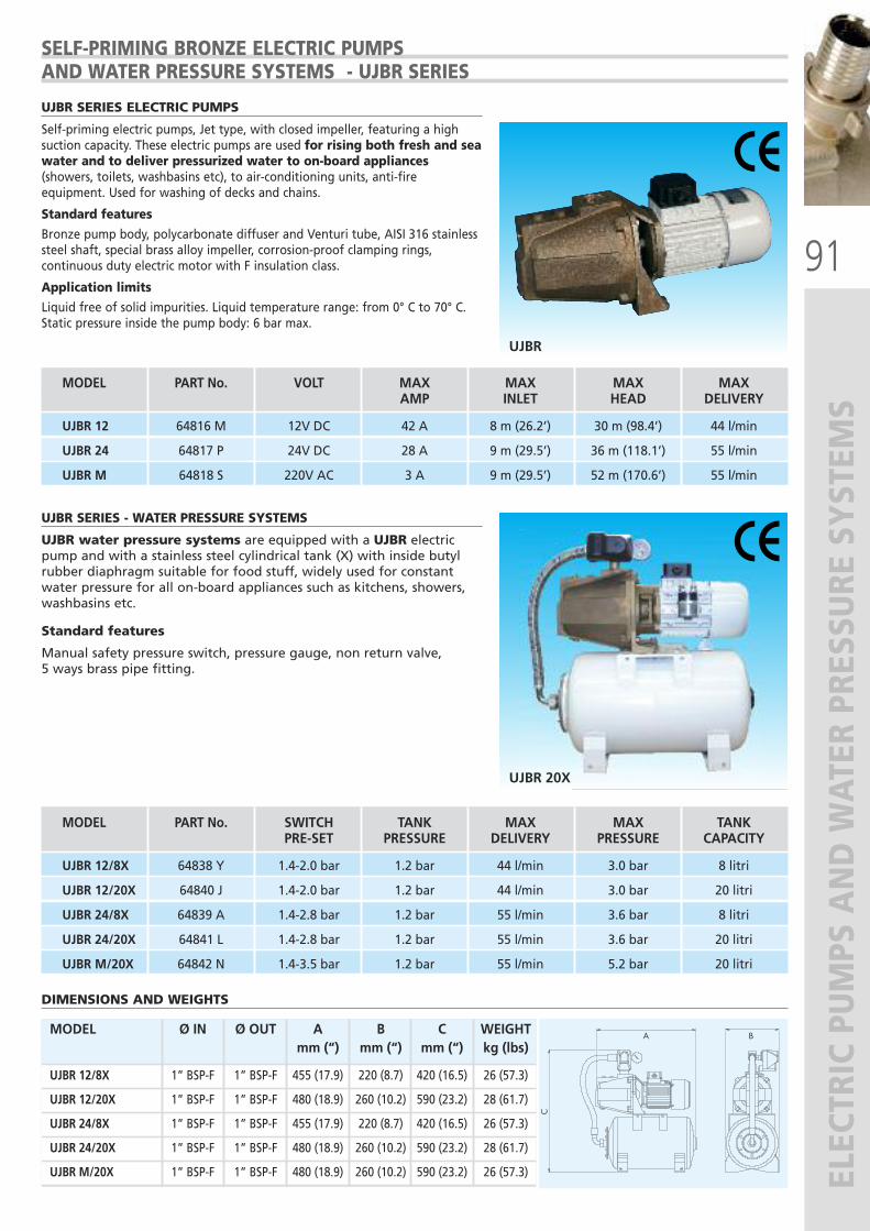
91
ELECTRIC PUMPS AND WATER PRESSURE SYSTEM
S
UJBR
SELF-PRIMING BRONZE ELECTRIC PUMPSAND WATER PRESSURE SYSTEMS - UJBR SERIES
UJBR SERIES ELECTRIC PUMPS
Self-priming electric pumps, Jet type, with closed impeller, featuring a highsuction capacity. These electric pumps are used for rising both fresh and seawater and to deliver pressurized water to on-board appliances(showers, toilets, washbasins etc), to air-conditioning units, anti-fireequipment. Used for washing of decks and chains.
Standard features
Bronze pump body, polycarbonate diffuser and Venturi tube, AISI 316 stainlesssteel shaft, special brass alloy impeller, corrosion-proof clamping rings,continuous duty electric motor with F insulation class.
Application limits
Liquid free of solid impurities. Liquid temperature range: from 0° C to 70° C.Static pressure inside the pump body: 6 bar max.
UJBR 20X
UJBR SERIES - WATER PRESSURE SYSTEMS
UJBR water pressure systems are equipped with a UJBR electricpump and with a stainless steel cylindrical tank (X) with inside butylrubber diaphragm suitable for food stuff, widely used for constantwater pressure for all on-board appliances such as kitchens, showers,washbasins etc.
Standard features
Manual safety pressure switch, pressure gauge, non return valve, 5 ways brass pipe fitting.
DIMENSIONS AND WEIGHTS
MODEL Ø IN Ø OUT A B C WEIGHT
mm (“) mm (“) mm (“) kg (lbs)
UJBR 12/8X 1” BSP-F 1” BSP-F 455 (17.9) 220 (8.7) 420 (16.5) 26 (57.3)
UJBR 12/20X 1” BSP-F 1” BSP-F 480 (18.9) 260 (10.2) 590 (23.2) 28 (61.7)
UJBR 24/8X 1” BSP-F 1” BSP-F 455 (17.9) 220 (8.7) 420 (16.5) 26 (57.3)
UJBR 24/20X 1” BSP-F 1” BSP-F 480 (18.9) 260 (10.2) 590 (23.2) 28 (61.7)
UJBR M/20X 1” BSP-F 1” BSP-F 480 (18.9) 260 (10.2) 590 (23.2) 26 (57.3)
MODEL PART No. VOLT MAX MAX MAX MAX AMP INLET HEAD DELIVERY
UJBR 12 64816 M 12V DC 42 A 8 m (26.2’) 30 m (98.4’) 44 l/min
UJBR 24 64817 P 24V DC 28 A 9 m (29.5’) 36 m (118.1’) 55 l/min
UJBR M 64818 S 220V AC 3 A 9 m (29.5’) 52 m (170.6’) 55 l/min
MODEL PART No. SWITCH TANK MAX MAX TANK PRE-SET PRESSURE DELIVERY PRESSURE CAPACITY
UJBR 12/8X 64838 Y 1.4-2.0 bar 1.2 bar 44 l/min 3.0 bar 8 litri
UJBR 12/20X 64840 J 1.4-2.0 bar 1.2 bar 44 l/min 3.0 bar 20 litri
UJBR 24/8X 64839 A 1.4-2.8 bar 1.2 bar 55 l/min 3.6 bar 8 litri
UJBR 24/20X 64841 L 1.4-2.8 bar 1.2 bar 55 l/min 3.6 bar 20 litri
UJBR M/20X 64842 N 1.4-3.5 bar 1.2 bar 55 l/min 5.2 bar 20 litri
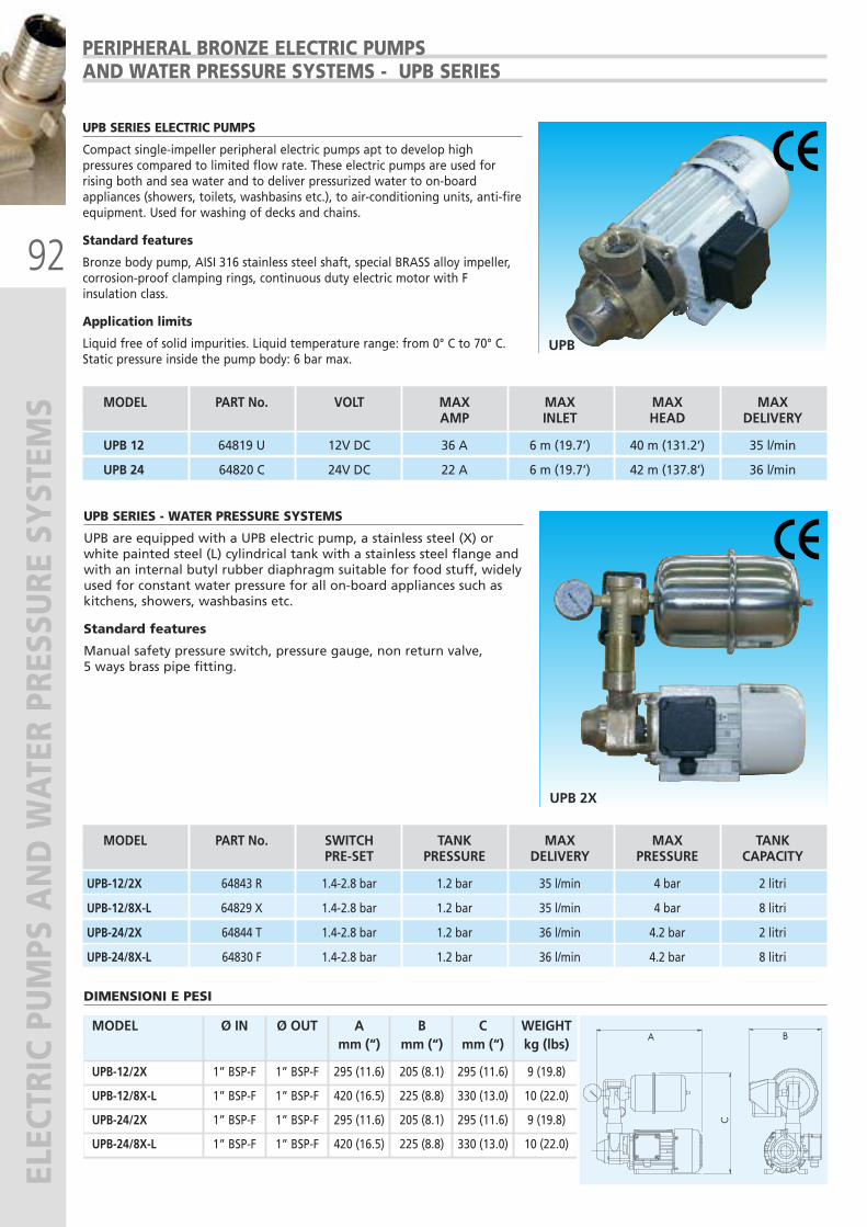
92
ELECTRIC PUMPS AND WATER PRESSURE SYSTEM
S
UPB
PERIPHERAL BRONZE ELECTRIC PUMPSAND WATER PRESSURE SYSTEMS - UPB SERIES
UPB SERIES ELECTRIC PUMPS
Compact single-impeller peripheral electric pumps apt to develop highpressures compared to limited flow rate. These electric pumps are used forrising both and sea water and to deliver pressurized water to on-boardappliances (showers, toilets, washbasins etc.), to air-conditioning units, anti-fireequipment. Used for washing of decks and chains.
Standard features
Bronze body pump, AISI 316 stainless steel shaft, special BRASS alloy impeller,corrosion-proof clamping rings, continuous duty electric motor with Finsulation class.
Application limits
Liquid free of solid impurities. Liquid temperature range: from 0° C to 70° C.Static pressure inside the pump body: 6 bar max.
UPB 2X
UPB SERIES - WATER PRESSURE SYSTEMS
UPB are equipped with a UPB electric pump, a stainless steel (X) orwhite painted steel (L) cylindrical tank with a stainless steel flange andwith an internal butyl rubber diaphragm suitable for food stuff, widelyused for constant water pressure for all on-board appliances such askitchens, showers, washbasins etc.
Standard features
Manual safety pressure switch, pressure gauge, non return valve, 5 ways brass pipe fitting.
DIMENSIONI E PESI
MODEL Ø IN Ø OUT A B C WEIGHT
mm (“) mm (“) mm (“) kg (lbs)
UPB-12/2X 1” BSP-F 1” BSP-F 295 (11.6) 205 (8.1) 295 (11.6) 9 (19.8)
UPB-12/8X-L 1” BSP-F 1” BSP-F 420 (16.5) 225 (8.8) 330 (13.0) 10 (22.0)
UPB-24/2X 1” BSP-F 1” BSP-F 295 (11.6) 205 (8.1) 295 (11.6) 9 (19.8)
UPB-24/8X-L 1” BSP-F 1” BSP-F 420 (16.5) 225 (8.8) 330 (13.0) 10 (22.0)
MODEL PART No. SWITCH TANK MAX MAX TANK PRE-SET PRESSURE DELIVERY PRESSURE CAPACITY
UPB-12/2X 64843 R 1.4-2.8 bar 1.2 bar 35 l/min 4 bar 2 litri
UPB-12/8X-L 64829 X 1.4-2.8 bar 1.2 bar 35 l/min 4 bar 8 litri
UPB-24/2X 64844 T 1.4-2.8 bar 1.2 bar 36 l/min 4.2 bar 2 litri
UPB-24/8X-L 64830 F 1.4-2.8 bar 1.2 bar 36 l/min 4.2 bar 8 litri
MODEL PART No. VOLT MAX MAX MAX MAX AMP INLET HEAD DELIVERY
UPB 12 64819 U 12V DC 36 A 6 m (19.7’) 40 m (131.2’) 35 l/min
UPB 24 64820 C 24V DC 22 A 6 m (19.7’) 42 m (137.8’) 36 l/min

93
TWIN WATER PRESSURE SYSTEM
S MODEL PART No. PUMP 1 PUMP 2 MOTOR POWER CURRENT MAX MAX Kw A DELIVERY PRESSURE
UGA1/J 66332 Z UJ-INOX 24 UJ-INOX 24 DC+DC 0,6+0,6 28+28 50+50 l/min. 3.8 bar
UGA2/J 66333 B UJ-INOX M UJ-INOX M AC+AC 0,6+0,6 / 50+50 l/min. 4 bar
UGA3/J 66334 D UJ-INOX 24 UJ-INOX M DC+AC 0,6+0,6 28+/ 50+50 l/min. 4 bar
UGA1/MG 66335 F UMG-INOX 24 UMG-INOX 24 DC+DC 0,75+0,75 40+40 90+90 l/min. 5 bar
UGA2/MG 66336 H UMG-INOX M UMG-INOX M AC+AC 0,75+0,75 / 90+90 l/min. 5 bar
UGA3/MG 66337 K UMG-INOX 24 UMG-INOX M DC+AC 0,75+0,75 40+/ 90+90 l/min. 5 bar
UGA1/JBR 66338 M UJBR 24 UJBR 24 DC+DC 0,6+0,6 28+28 55+55 l/min. 3,6 bar
UGA2/JBR 66339 P UJBR M UJBR M AC+AC 0,6+0,6 / 55+55 l/min. 5 bar
UGA3/JBR 66340 Y UJBR 24 UJBR M DC+AC 0,6+0,6 28+/ 55+55 l/min. 5 bar
UGA 1/J - UGA1/MG
UGA1/JBR
TWIN WATER PRESSURE SYSTEMS
Twin water pressure systems including 2 self-priming electric pumps(UJ-INOX or UMG-INOX stainless steel made), or 2 self priming electricpumps (UJBR bronze made), widely used in the marine field to granta proper and constant water pressure for all on board utilities such as:showers, kitchen, washbasins, toilets, etc.With this peculiar application a double flow rate can be obtained andthe system can face an emergency stop of one of the pumps duringnavigation.The use of twin water pressure systems UGA-J, UGA-MG and UGA-JBRSeries allows a water capacity higher than the traditional pressure sets,as the two pumps, whatever DC, AC, or mixed DC and AC, can workeither simultaneously or singularly.For a proper operation of the group, a water tank is recommended.
Vertical twin water pressure systems are available on request.
TWIN WATER PRESSURE SYSTEMS
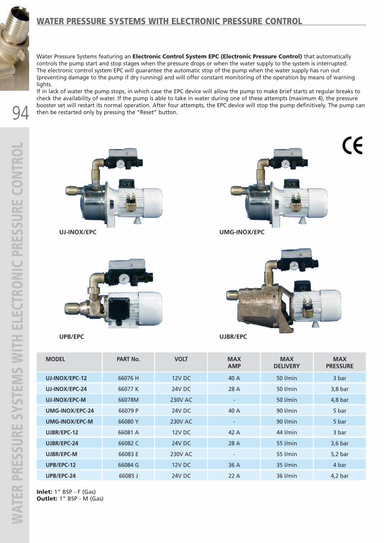
94
WATER PRESSURE SYSTEM
S WITH ELECTRON
IC PRESSURE CO
NTRO
L
UPB/EPC
UJ-INOX/EPC
UJBR/EPC
UMG-INOX/EPC
WATER PRESSURE SYSTEMS WITH ELECTRONIC PRESSURE CONTROL
Water Pressure Systems featuring an Electronic Control System EPC (Electronic Pressure Control) that automaticallycontrols the pump start and stop stages when the pressure drops or when the water supply to the system is interrupted. The electronic control system EPC will guarantee the automatic stop of the pump when the water supply has run out(preventing damage to the pump if dry running) and will offer constant monitoring of the operation by means of warninglights.If in lack of water the pump stops, in which case the EPC device will allow the pump to make brief starts at regular breaks tocheck the availability of water. If the pump is able to take in water during one of these attempts (maximum 4), the pressurebooster set will restart its normal operation. After four attempts, the EPC device will stop the pump definitively. The pump canthen be restarted only by pressing the “Reset” button.
Inlet: 1” BSP - F (Gas)Outlet: 1” BSP - M (Gas)
MODEL PART No. VOLT MAX MAX MAX AMP DELIVERY PRESSURE
UJ-INOX/EPC-12 66076 H 12V DC 40 A 50 l/min 3 bar
UJ-INOX/EPC-24 66077 K 24V DC 28 A 50 l/min 3,8 bar
UJ-INOX/EPC-M 66078M 230V AC - 50 l/min 4,8 bar
UMG-INOX/EPC-24 66079 P 24V DC 40 A 90 l/min 5 bar
UMG-INOX/EPC-M 66080 Y 230V AC - 90 l/min 5 bar
UJBR/EPC-12 66081 A 12V DC 42 A 44 l/min 3 bar
UJBR/EPC-24 66082 C 24V DC 28 A 55 l/min 3,6 bar
UJBR/EPC-M 66083 E 230V AC - 55 l/min 5,2 bar
UPB/EPC-12 66084 G 12V DC 36 A 35 l/min 4 bar
UPB/EPC-24 66085 J 24V DC 22 A 36 l/min 4,2 bar
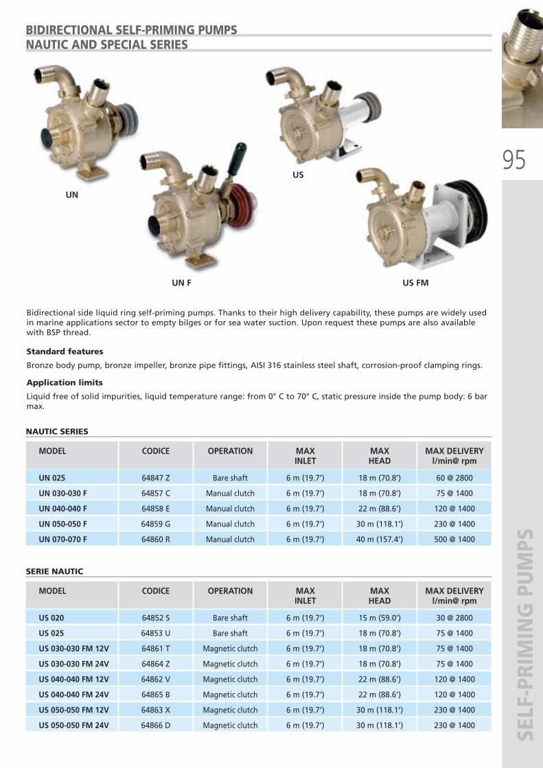
95
SELF-PRIMING PUMPS
BIDIRECTIONAL SELF-PRIMING PUMPSNAUTIC AND SPECIAL SERIES
UN
UN F US FM
Bidirectional side liquid ring self-priming pumps. Thanks to their high delivery capability, these pumps are widely usedin marine applications sector to empty bilges or for sea water suction. Upon request these pumps are also availablewith BSP thread.
Standard features
Bronze body pump, bronze impeller, bronze pipe fittings, AISI 316 stainless steel shaft, corrosion-proof clamping rings.
Application limits
Liquid free of solid impurities, liquid temperature range: from 0° C to 70° C, static pressure inside the pump body: 6 barmax.
NAUTIC SERIES
US
MODEL CODICE OPERATION MAX MAX MAX DELIVERY INLET HEAD l/min@ rpm
UN 025 64847 Z Bare shaft 6 m (19.7’) 18 m (70.8’) 60 @ 2800
UN 030-030 F 64857 C Manual clutch 6 m (19.7’) 18 m (70.8’) 75 @ 1400
UN 040-040 F 64858 E Manual clutch 6 m (19.7’) 22 m (88.6’) 120 @ 1400
UN 050-050 F 64859 G Manual clutch 6 m (19.7’) 30 m (118.1’) 230 @ 1400
UN 070-070 F 64860 R Manual clutch 6 m (19.7’) 40 m (157.4’) 500 @ 1400
SERIE NAUTIC
MODEL CODICE OPERATION MAX MAX MAX DELIVERY INLET HEAD l/min@ rpm
US 020 64852 S Bare shaft 6 m (19.7’) 15 m (59.0’) 30 @ 2800
US 025 64853 U Bare shaft 6 m (19.7’) 18 m (70.8’) 75 @ 1400
US 030-030 FM 12V 64861 T Magnetic clutch 6 m (19.7’) 18 m (70.8’) 75 @ 1400
US 030-030 FM 24V 64864 Z Magnetic clutch 6 m (19.7’) 18 m (70.8’) 75 @ 1400
US 040-040 FM 12V 64862 V Magnetic clutch 6 m (19.7’) 22 m (88.6’) 120 @ 1400
US 040-040 FM 24V 64865 B Magnetic clutch 6 m (19.7’) 22 m (88.6’) 120 @ 1400
US 050-050 FM 12V 64863 X Magnetic clutch 6 m (19.7’) 30 m (118.1’) 230 @ 1400
US 050-050 FM 24V 64866 D Magnetic clutch 6 m (19.7’) 30 m (118.1’) 230 @ 1400
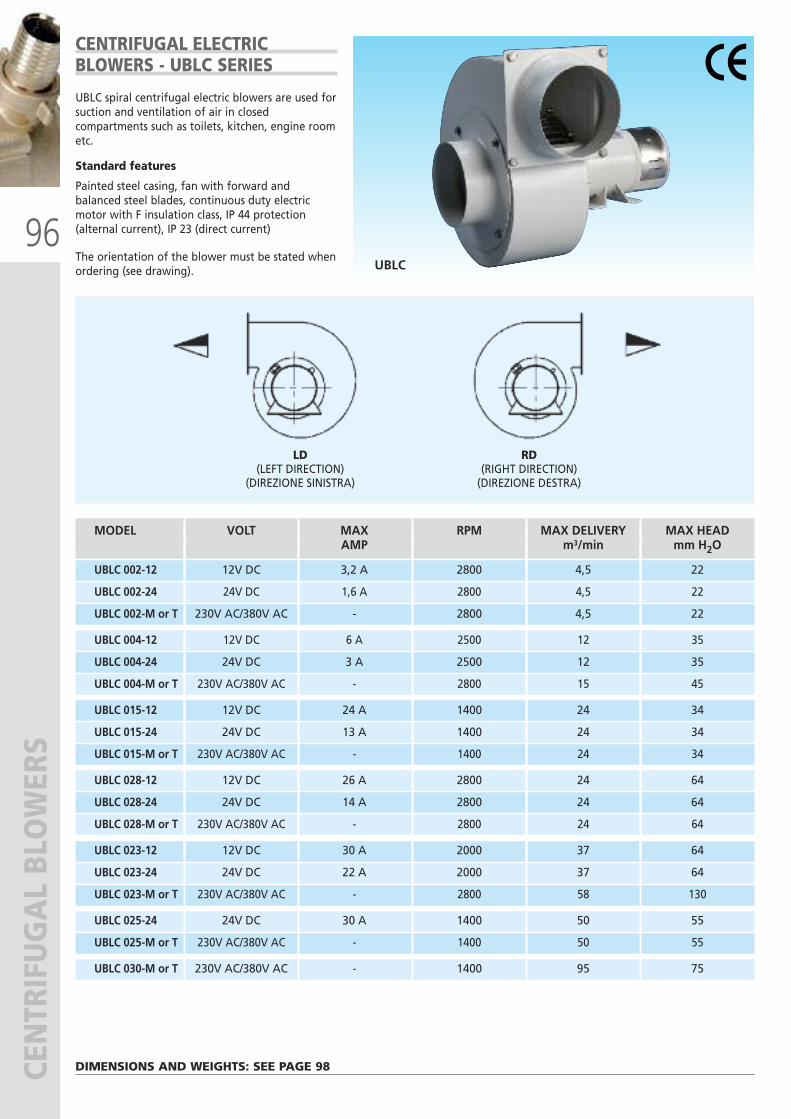
96
CENTRIFUGAL BLOWERS
UBLC
CENTRIFUGAL ELECTRIC BLOWERS - UBLC SERIES
UBLC spiral centrifugal electric blowers are used forsuction and ventilation of air in closedcompartments such as toilets, kitchen, engine roometc.
Standard features
Painted steel casing, fan with forward andbalanced steel blades, continuous duty electricmotor with F insulation class, IP 44 protection(alternal current), IP 23 (direct current)
The orientation of the blower must be stated whenordering (see drawing).
DIMENSIONS AND WEIGHTS: SEE PAGE 98
MODEL VOLT MAX RPM MAX DELIVERY MAX HEAD AMP m3/min mm H2O
UBLC 002-12 12V DC 3,2 A 2800 4,5 22
UBLC 002-24 24V DC 1,6 A 2800 4,5 22
UBLC 002-M or T 230V AC/380V AC - 2800 4,5 22
UBLC 004-12 12V DC 6 A 2500 12 35
UBLC 004-24 24V DC 3 A 2500 12 35
UBLC 004-M or T 230V AC/380V AC - 2800 15 45
UBLC 015-12 12V DC 24 A 1400 24 34
UBLC 015-24 24V DC 13 A 1400 24 34
UBLC 015-M or T 230V AC/380V AC - 1400 24 34
UBLC 028-12 12V DC 26 A 2800 24 64
UBLC 028-24 24V DC 14 A 2800 24 64
UBLC 028-M or T 230V AC/380V AC - 2800 24 64
UBLC 023-12 12V DC 30 A 2000 37 64
UBLC 023-24 24V DC 22 A 2000 37 64
UBLC 023-M or T 230V AC/380V AC - 2800 58 130
UBLC 025-24 24V DC 30 A 1400 50 55
UBLC 025-M or T 230V AC/380V AC - 1400 50 55
UBLC 030-M or T 230V AC/380V AC - 1400 95 75
LD(LEFT DIRECTION)
(DIREZIONE SINISTRA)
RD(RIGHT DIRECTION)(DIREZIONE DESTRA)

97
HELICOIDAL BLOWERS
UVE
MODEL VOLT MAX RPM MAX DELIVERY MAX HEAD AMP m3/min mm H2O
UVE 21-12 12V DC 12 A 2800 22 14 UVE 21-24 24V DC 6 A 2800 22 14
UVE 25-12 12V DC 22 A 2500 30 13 UVE 25-24 24V DC 11A 2500 30 13 UVE 25-M or T 230V AC/380V AC - 2800 35 14
UVE 30-12 12V DC 10 A 1400 42 8 UVE 30-24 24V DC 5 A 1400 42 8 UVE 30-M or T 230V AC/380V AC 1400 42 8
UVE 30/2-24 24V DC 14 A 2000 75 22 UVE 30/2-M or T 230V AC/380V AC 2800 78 35
UVE 35-12 12V DC 12 A 1400 56 13 UVE 35-24 24V DC 6 A 1400 56 13 UVE 35-M or T 230V AC/380V AC - 1400 56 13
UVE 35/2-24 24V DC 16 A 2000 96 18 UVE 35/2-M or T 230V AC/380V AC - 2800 100 46
UVE 40-12 12V DC 14 A 1400 70 14 UVE 40-24 24V DC 7 A 1400 70 14 UVE 40-M or T 230V AC/380V AC - 1400 70 14
UVE 40/2-24 24V DC 18 A 2000 130 24 UVE 40/2-M or T 230V AC/380V AC - 2800 130 40
UVE 45-24 24V DC 9 A 1400 107 17 UVE 45-M or T 230V AC/380V AC - 1400 107 17
UVE 45/2-24 24V DC 22 A 2000 144 28 UVE 45/2-M or T 230V AC/380V AC - 2800 175 51
UVE 50-24 24V DC 38 A 1400 160 20 UVE 50-M or T 230V AC/380V AC - 1400 160 20
UVE 56-24 24V DC 40 A 1400 225 23 UVE 56-M or T 230V AC/380V AC - 1400 225 23
UVE 63-M or T 230V AC/380V AC - 1400 312 32
UVE 71-T 380V AC - 1400 330 30
UVE 71/B or T 380V AC - 1400 400 40
DIMENSIONS AND WEIGHTS: SEE PAGE 98
HELICOIDAL ELECTRIC BLOWERS - UVE SERIES
UVE helicoidal electric blowers are used for suctionand ventilation of air in closed compartments suchas toilets, kitchen and engine rooms.
Standard features
Painted sheet steel drum, polypropylene balancedfan (temperature range: from -5° C to 70° C),continuous duty electric motor with F insulationclass, IP 44 protection.
The orientation of the blower must be specifiedwhen ordering (see drawing below).
RETE DI PROTEZIONEPROTECTION GRID
A
A
TIPO/TYPEA
FLUSSOFLUX
RETE DI PROTEZIONEPROTECTION GRID
P
P
FLUSSOFLUX
TIPO/TYPEP
FLUX A = Blower
FLUX P = Extractor
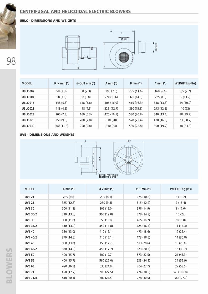
98
BLOWERS
CENTRIFUGAL AND HELICOIDAL ELECTRIC BLOWERS
UBLC - DIMENSIONS AND WEIGHTS
MODEL Ø IN mm (”) Ø OUT mm (”) A mm (”) B mm (”) C mm (”) WEIGHT kg (lbs)
UBLC 002 58 (2.3) 58 (2.3) 190 (7.5) 295 (11.6) 168 (6.6) 3,5 (7.7)
UBLC 004 98 (3.8) 98 (3.8) 270 (10.6) 370 (14.6) 225 (8.8) 6 (13.2)
UBLC 015 148 (5.8) 148 (5.8) 405 (16.0) 415 (16.3) 338 (13.3) 14 (30.9)
UBLC 028 118 (4.6) 118 (4.6) 322 (12.7) 390 (15.3) 273 (12.6) 10 (22)
UBLC 023 200 (7.8) 160 (6.3) 420 (16.5) 530 (20.8) 340 (13.4) 18 (39.7)
UBLC 025 250 (9.8) 200 (7.8) 510 (20) 570 (22.4) 420 (16.5) 23 (50.7)
UBLC 030 300 (11.8) 250 (9.8) 610 (24) 580 (22.8) 500 (19.7) 38 (83.8)
MODEL A mm (“) Ø V mm (“) Ø T mm (“) WEIGHT Kg (lbs)
UVE 21 255 (10) 205 (8.1) 275 (10.8) 6 (13.2)
UVE 25 325 (12.8) 250 (9.8) 315 (12.2) 7 (15.4)
UVE 30 300 (11.8) 305 (12.0) 378 (14.9) 8 (17.6)
UVE 30/2 330 (13.0) 305 (12.0) 378 (14.9) 10 (22)
UVE 35 300 (11.8) 350 (13.8) 425 (16.7) 9 (19.8)
UVE 35/2 330 (13.0) 350 (13.8) 425 (16.7) 11 (14.3)
UVE 40 330 (13.0) 410 (16.1) 473 (18.6) 12 (26.4)
UVE 40/2 370 (14.5) 410 (16.1) 473 (18.6) 14 (30.8)
UVE 45 330 (13.0) 450 (17.7) 523 (20.6) 13 (28.6)
UVE 45/2 380 (14.9) 450 (17.7) 523 (20.6) 18 (39.7)
UVE 50 400 (15.7) 500 (19.7) 573 (22.5) 21 (46.3)
UVE 56 400 (15.7) 560 (22.0) 633 (24.9) 24 (52.9)
UVE 63 420 (16.5) 630 (24.8) 704 (27.7) 27 (59.5)
UVE 71 450 (17.7) 700 (27.5) 774 (30.5) 48 (105.8)
UVE 71/B 510 (20.1) 700 (27.5) 774 (30.5) 58 (127.9)
UVE - DIMENSIONS AND WEIGHTS
Ø T
Ø V
A
RETE DI PROTEZIONEPROTECTION GRID
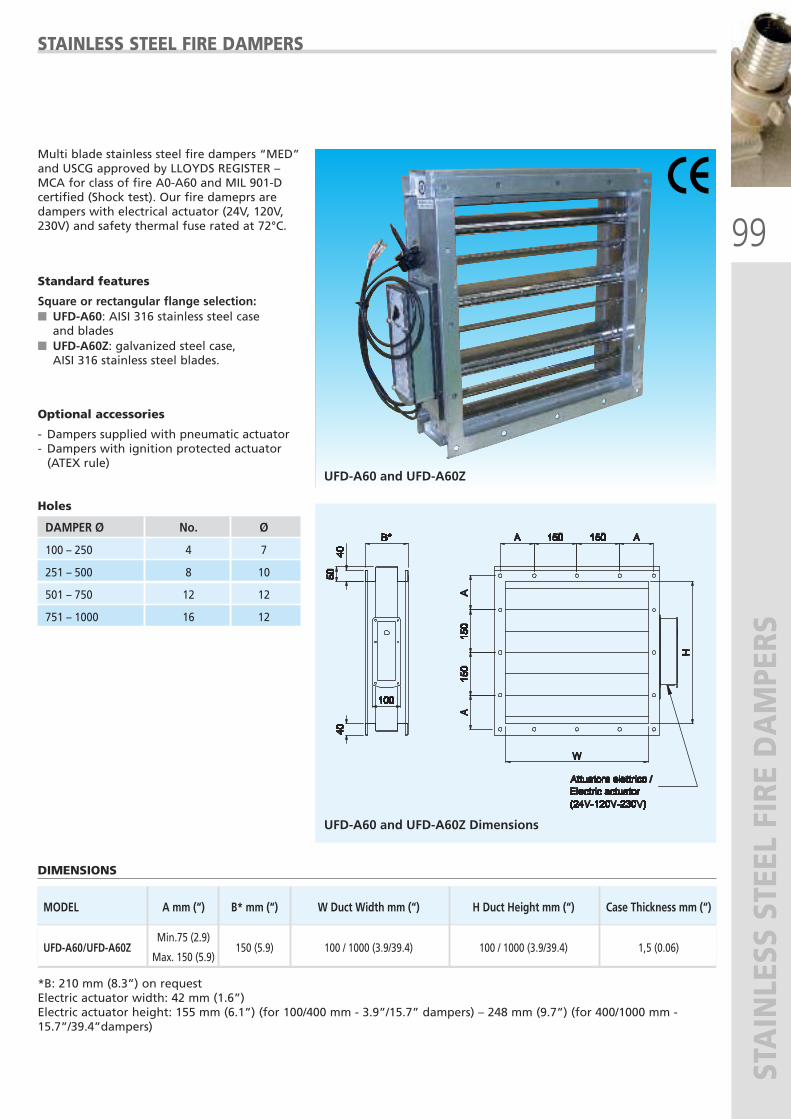
99
STAINLESS STEEL FIRE DAMPERS
UFD-A60 and UFD-A60Z
STAINLESS STEEL FIRE DAMPERS
Multi blade stainless steel fire dampers “MED”and USCG approved by LLOYDS REGISTER –MCA for class of fire A0-A60 and MIL 901-Dcertified (Shock test). Our fire dameprs aredampers with electrical actuator (24V, 120V,230V) and safety thermal fuse rated at 72°C.
Standard features
Square or rectangular flange selection:� UFD-A60: AISI 316 stainless steel case and blades
� UFD-A60Z: galvanized steel case, AISI 316 stainless steel blades.
Optional accessories
- Dampers supplied with pneumatic actuator- Dampers with ignition protected actuator (ATEX rule)
Holes
DIMENSIONS
MODEL A mm (“) B* mm (“) W Duct Width mm (“) H Duct Height mm (“) Case Thickness mm (“)
Min.75 (2.9)
UFD-A60/UFD-A60Z
Max. 150 (5.9) 150 (5.9) 100 / 1000 (3.9/39.4) 100 / 1000 (3.9/39.4) 1,5 (0.06)
UFD-A60 and UFD-A60Z Dimensions
*B: 210 mm (8.3”) on requestElectric actuator width: 42 mm (1.6”)Electric actuator height: 155 mm (6.1”) (for 100/400 mm - 3.9”/15.7” dampers) – 248 mm (9.7”) (for 400/1000 mm -15.7”/39.4”dampers)
DAMPER Ø No. Ø
100 – 250 4 7
251 – 500 8 10
501 – 750 12 12
751 – 1000 16 12
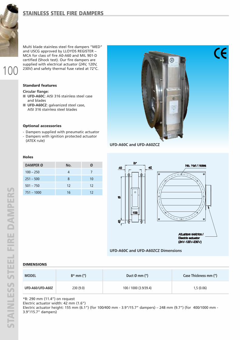
100
STAINLESS STEEL FIRE DAMPERS
UFD-A60C and UFD-A60ZCZ
STAINLESS STEEL FIRE DAMPERS
Multi blade stainless steel fire dampers “MED”and USCG approved by LLOYDS REGISTER –MCA for class of fire A0-A60 and MIL 901-Dcertified (Shock test). Our fire dampers aresupplied with electrical actuator (24V, 120V,230V) and safety thermal fuse rated at 72°C.
Standard features
Circular flange:� UFD-A60C: AISI 316 stainless steel case and blades
� UFD-A60CZ: galvanized steel case, AISI 316 stainless steel blades
Optional accessories
- Dampers supplied with pneumatic actuator- Dampers with ignition protected actuator (ATEX rule)
Holes
DIMENSIONS
MODEL B* mm (“) Duct Ø mm (“) Case Thickness mm (“)
UFD-A60/UFD-A60Z 230 (9.0) 100 / 1000 (3.9/39.4) 1,5 (0.06)
UFD-A60C and UFD-A60ZCZ Dimensions
*B: 290 mm (11.4”) on requestElectric actuator width: 42 mm (1.6”)Electric actuator height: 155 mm (6.1”) (for 100/400 mm - 3.9”/15.7” dampers) – 248 mm (9.7”) (for 400/1000 mm -3.9”/15.7” dampers)
DAMPER Ø No. Ø
100 – 250 4 7
251 – 500 8 10
501 – 750 12 12
751 – 1000 16 12

101
MARINE ELECTRICAL EQUIPMENTS
QUALITY MARINE ELECTRICAL PRODUCTS
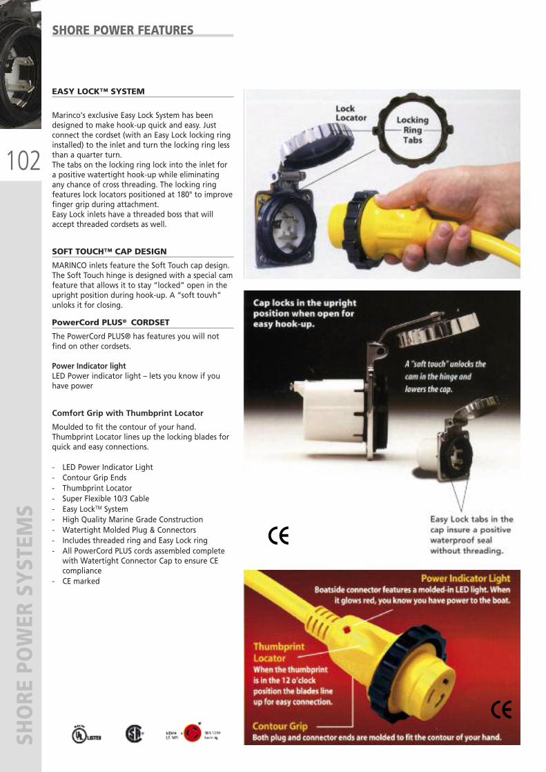
102
SHORE POWER SYSTEM
SSHORE POWER FEATURES
EASY LOCK™ SYSTEM
Marinco’s exclusive Easy Lock System has beendesigned to make hook-up quick and easy. Justconnect the cordset (with an Easy Lock locking ringinstalled) to the inlet and turn the locking ring lessthan a quarter turn.The tabs on the locking ring lock into the inlet fora positive watertight hook-up while eliminatingany chance of cross threading. The locking ringfeatures lock locators positioned at 180° to improvefinger grip during attachment.Easy Lock inlets have a threaded boss that willaccept threaded cordsets as well.
SOFT TOUCH™ CAP DESIGN
MARINCO inlets feature the Soft Touch cap design.The Soft Touch hinge is designed with a special camfeature that allows it to stay “locked” open in theupright position during hook-up. A “soft touvh”unloks it for closing.
PowerCord PLUS® CORDSET
The PowerCord PLUS® has features you will notfind on other cordsets.
Power Indicator lightLED Power indicator light – lets you know if youhave power
Comfort Grip with Thumbprint Locator
Moulded to fit the contour of your hand.Thumbprint Locator lines up the locking blades forquick and easy connections.
- LED Power Indicator Light- Contour Grip Ends- Thumbprint Locator- Super Flexible 10/3 Cable- Easy LockTM System- High Quality Marine Grade Construction- Watertight Molded Plug & Connectors- Includes threaded ring and Easy Lock ring- All PowerCord PLUS cords assembled completewith Watertight Connector Cap to ensure CEcompliance
- CE marked
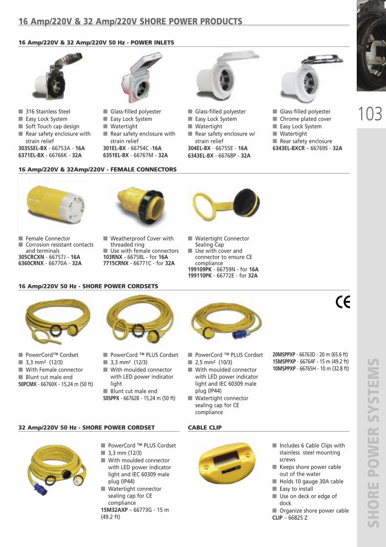
103
SHORE POWER SYSTEM
S
16 Amp/220V & 32 Amp/220V SHORE POWER PRODUCTS
� 316 Stainless Steel� Easy Lock System� Soft Touch cap design� Rear safety enclosure with strain relief
303SSEL-BX - 66753A - 16A6371EL-BX - 66766K - 32A
� Glass-filled polyester� Easy Lock System� Watertight� Rear safety enclosure withstrain relief
301EL-BX - 66754C -16A6351EL-BX - 66767M - 32A
� Glass-filled polyester� Easy Lock System� Watertight� Rear safety enclosure w/strain relief
304EL-BX - 66755E - 16A 6343EL-BX - 66768P - 32A
� Glass-filled polyester� Chrome plated cover � Easy Lock System� Watertight� Rear safety enclosure 6343EL-BXCR – 66769S - 32A
16 Amp/220V & 32 Amp/220V 50 Hz - POWER INLETS
� Female Connector� Corrosion resistant contactsand terminals
305CRCXN - 66757J - 16A6360CRNX - 66770A - 32A
� Weatherproof Cover withthreaded ring
� Use with female connectors103RNX - 66758L - for 16A7715CRNX - 66771C - for 32A
� Watertight Connector Sealing Cap
� Use with cover andconnector to ensure CE compliance
199109PK - 66759N - for 16A199110PK - 66772E - for 32A
16 Amp/220V & 32Amp/220V - FEMALE CONNECTORS
16 Amp/220V 50 Hz - SHORE POWER CORDSETS
� PowerCord ™ PLUS Cordset� 3,3 mm (12/3)� With moulded connectorwith LED power indicatorlight and IEC 60309 maleplug (IP44)
� Watertight connectorsealing cap for CEcompliance
15M32AXP – 66773G - 15 m(49.2 ft)
32 Amp/220V 50 Hz - SHORE POWER CORDSET
� Includes 6 Cable Clips withstainless steel mountingscrews
� Keeps shore power cableout of the water
� Holds 10 gauge 30A cable� Easy to install� Use on deck or edge ofdock
� Organize shore power cableCLIP – 66825 Z
CABLE CLIP
� PowerCord™ Cordset� 3,3 mm² (12/3)� With Female connector� Blunt cut male end50PCMX - 66760X - 15,24 m (50 ft)
� PowerCord ™ PLUS Cordset� 3,3 mm² (12/3)� With moulded connectorwith LED power indicatorlight
� Blunt cut male end50SPPX - 66762B - 15,24 m (50 ft)
� PowerCord ™ PLUS Cordset� 2,5 mm² (10/3)� With moulded connectorwith LED power indicatorlight and IEC 60309 maleplug (IP44)
� Watertight connectorsealing cap for CEcompliance
20MSPPXP - 66763D - 20 m (65.6 ft)15MSPPXP - 66764F - 15 m (49.2 ft)10MSPPXP - 66765H - 10 m (32.8 ft)
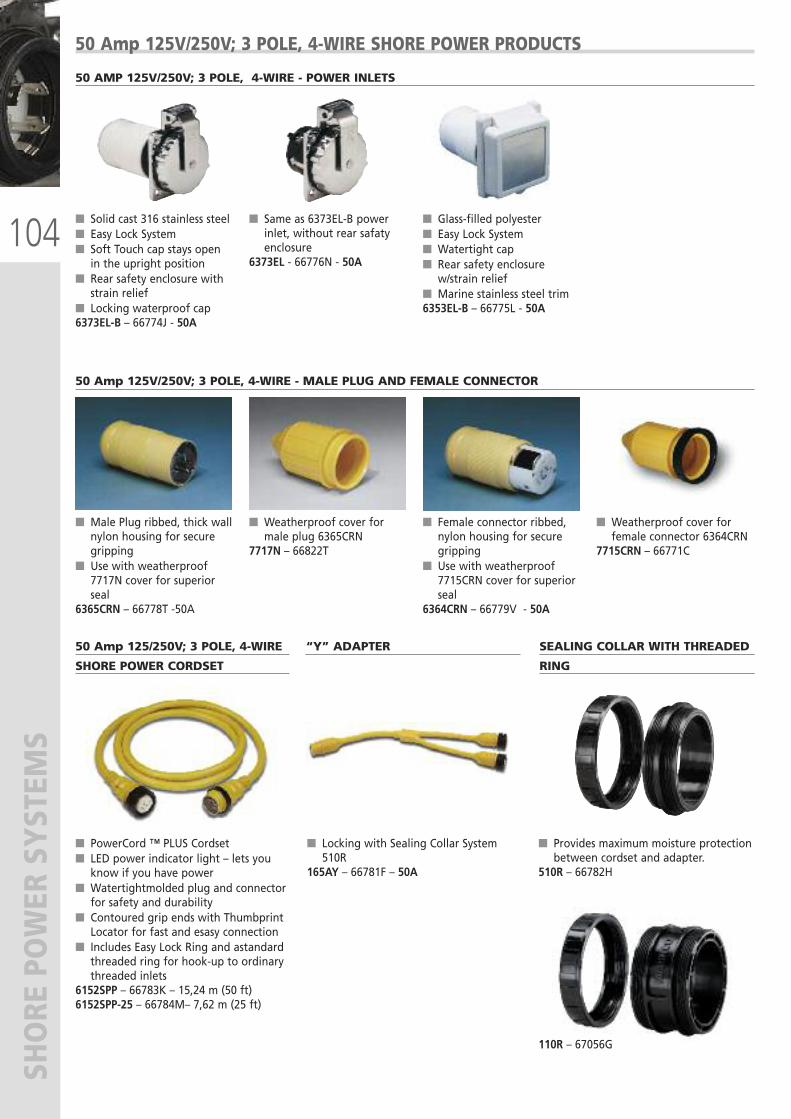
104
SHORE POWER SYSTEM
S50 Amp 125V/250V; 3 POLE, 4-WIRE SHORE POWER PRODUCTS
� Solid cast 316 stainless steel� Easy Lock System� Soft Touch cap stays openin the upright position
� Rear safety enclosure withstrain relief
� Locking waterproof cap6373EL-B – 66774J - 50A
� Same as 6373EL-B powerinlet, without rear safatyenclosure
6373EL - 66776N - 50A
� Glass-filled polyester� Easy Lock System� Watertight cap� Rear safety enclosurew/strain relief
� Marine stainless steel trim6353EL-B – 66775L - 50A
50 AMP 125V/250V; 3 POLE, 4-WIRE - POWER INLETS
� Male Plug ribbed, thick wallnylon housing for securegripping
� Use with weatherproof7717N cover for superiorseal
6365CRN – 66778T -50A
� Weatherproof cover formale plug 6365CRN
7717N – 66822T
� Female connector ribbed,nylon housing for securegripping
� Use with weatherproof7715CRN cover for superiorseal
6364CRN – 66779V - 50A
� Weatherproof cover forfemale connector 6364CRN
7715CRN – 66771C
50 Amp 125V/250V; 3 POLE, 4-WIRE - MALE PLUG AND FEMALE CONNECTOR
� PowerCord ™ PLUS Cordset � LED power indicator light – lets youknow if you have power
� Watertightmolded plug and connectorfor safety and durability
� Contoured grip ends with ThumbprintLocator for fast and esasy connection
� Includes Easy Lock Ring and astandardthreaded ring for hook-up to ordinarythreaded inlets
6152SPP – 66783K – 15,24 m (50 ft)6152SPP-25 – 66784M– 7,62 m (25 ft)
� Locking with Sealing Collar System510R
165AY – 66781F – 50A
� Provides maximum moisture protectionbetween cordset and adapter.
510R – 66782H
110R – 67056G
50 Amp 125/250V; 3 POLE, 4-WIRE
SHORE POWER CORDSET
“Y” ADAPTER SEALING COLLAR WITH THREADED
RING
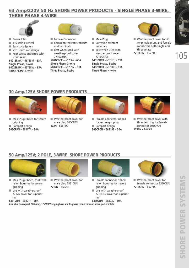
105
SHORE POWER SYSTEM
S
63 Amp/220V 50 Hz SHORE POWER PRODUCTS - SINGLE PHASE 3-WIRE,THREE PHASE 4-WIRE
� Power Inlet� 316 stainless steel� Easy Lock System� Soft Touch cap design� Rear safety enclosure withstrain relief
6401EL-BX – 66785M – 63ASingle Phase, 3-wire6402EL-BX – 66788W – 63AThree Phase, 4-wire
� Female Connector� Corrosion resistant contactsand terminals
� Best when used withweatherproof cover7715CRNX
6401CRCX – 66786S - 63ASingle Phase, 3-wire6402CRCX – 66789Y - 63A Three Phase, 4-wire
� Male Plug� Corrosion resistantmaterials
� Best when used withweatherproof cover7715CRNX
6401CRPX - 66787U - 63ASingle Phase, 3-wire6402CRPX - 66790G - 63AThree Phase, 4-wire
� Weatherproof cover for 63Amp male plugs and femaleconnectors both single andthree phase
7715CRN – 66771C
� Male Plug ribbed for securegripping
� Compact design305CRPN – 66817A - 30A
� Weatherproof cover formale plug 305CRPN
102N - 66818C
� Female Connector ribbedfor secure gripping
� Compact design305CRCN – 66819E – 30A
� Weatherproof cover withthreaded ring for femaleconnector 305CRCN
103RN – 66758L
30 Amp/125V SHORE POWER PRODUCTS
� Male Plug ribbed, thick wallnylon housing for securegripping
� Use with weatherproof7717N cover for superiorseal
6361CRN – 66821R - 50A
� Weatherproof cover formale plug 6361CRN
7717N – 66822T
� Female connector ribbed,nylon housing for securegripping
� Use with weatherproof7715CRN cover for superiorseal
6360CRN – 66823V - 50A
� Weatherproof cover forfemale connector 6360CRN
7715CRN – 66771C
50 Amp/125V; 2 POLE, 3-WIRE SHORE POWER PRODUCTS
Available on request, 100 Amp, 125/250V single-phase and tri-phase connectors and shore power inlets
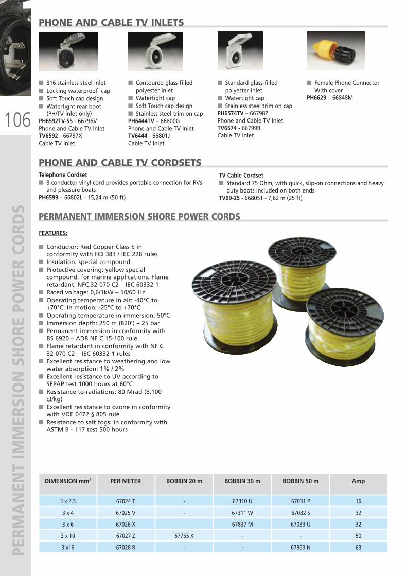
106
PERM
ANENT IMMERSION SHORE POWER CORD
S
� 316 stainless steel inlet � Locking waterproof cap� Soft Touch cap design� Watertight rear boot(PH/TV inlet only)
PH6592TV-SS - 66796VPhone and Cable TV InletTV6592 - 66797XCable TV Inlet
� Contoured glass-filledpolyester inlet
� Watertight cap� Soft Touch cap design� Stainless steel trim on capPH6444TV – 66800GPhone and Cable TV InletTV6444 - 66801JCable TV Inlet
� Standard glass-filledpolyester inlet
� Watertight cap� Stainless steel trim on capPH6574TV – 66798ZPhone and Cable TV InletTV6574 - 66799BCable TV Inlet
� Female Phone ConnectorWith cover
PH6629 – 66848M
PHONE AND CABLE TV INLETS
PHONE AND CABLE TV CORDSETSTV Cable Cordset� Standard 75 Ohm, with quick, slip-on connections and heavyduty boots included on both ends
TV99-25 - 66805T - 7,62 m (25 ft)
Telephone Cordset� 3 conductor vinyl cord provides portable connection for RVsand pleasure boats
PH6599 – 66802L - 15,24 m (50 ft)
PERMANENT IMMERSION SHORE POWER CORDS
FEATURES:
� Conductor: Red Copper Class 5 inconformity with HD 383 / IEC 228 rules
� Insulation: special compound� Protective covering: yellow specialcompound, for marine applications. Flameretardant: NFC.32-070 C2 – IEC 60332-1
� Rated voltage: 0,6/1kW – 50/60 Hz� Operating temperature in air: -40°C to+70°C. In motion: -25°C to +70°C
� Operating temperature in immersion: 50°C� Immersion depth: 250 m (820’) – 25 bar� Permanent immersion in conformity withBS 6920 – AD8 NF C 15-100 rule
� Flame retardant in conformity with NF C32-070 C2 – IEC 60332-1 rules
� Excellent resistance to weathering and lowwater absorption: 1% / 2%
� Excellent resistance to UV according toSEPAP test 1000 hours at 60°C
� Resistance to radiations: 80 Mrad (8.100cJ/kg)
� Excellent resistance to ozone in conformitywith VDE 0472 § 805 rule
� Resistance to salt fogs: in conformity withASTM B - 117 test 500 hours
DIMENSION mm2 PER METER BOBBIN 20 m BOBBIN 30 m BOBBIN 50 m Amp
3 x 2,5 67024 T - 67310 U 67031 P 16
3 x 4 67025 V - 67311 W 67032 S 32
3 x 6 67026 X - 67837 M 67033 U 32
3 x 10 67027 Z 67755 K - - 50
3 x16 67028 B - - 67863 N 63
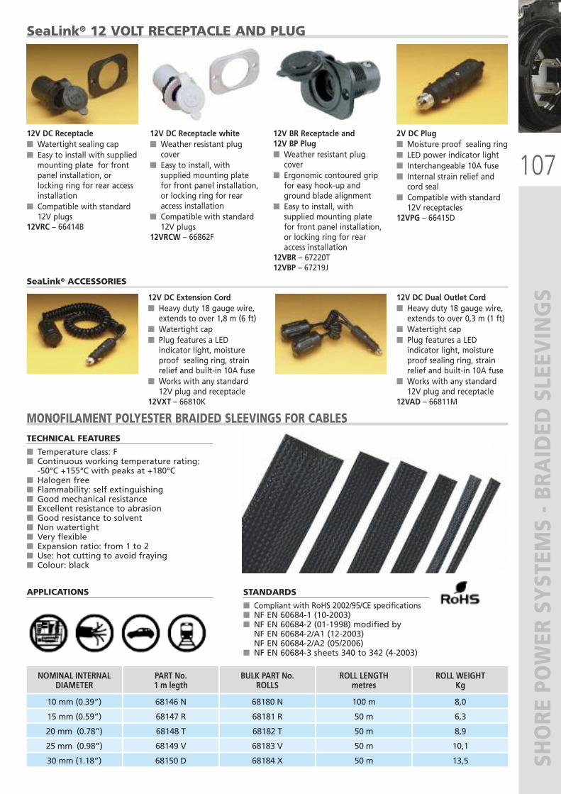
107
SHORE POWER SYSTEM
S - BRA
IDED SLEEVINGS
PART No.1 m legth
NOMINAL INTERNAL DIAMETER
68146 N10 mm (0.39”)
68147 R 15 mm (0.59”)
68148 T20 mm (0.78”)
68150 D30 mm (1.18”)
68149 V
BULK PART No. ROLLS
68180 N
68181 R
68182 T
68184 X
68183 V
ROLL LENGTHmetres
100 m
50 m
50 m
50 m
50 m
ROLL WEIGHTKg
8,0
6,3
8,9
13,5
10,125 mm (0.98”)
TECHNICAL FEATURES
� Temperature class: F� Continuous working temperature rating: -50°C +155°C with peaks at +180°C
� Halogen free� Flammability: self extinguishing� Good mechanical resistance� Excellent resistance to abrasion� Good resistance to solvent� Non watertight� Very flexible� Expansion ratio: from 1 to 2� Use: hot cutting to avoid fraying� Colour: black
APPLICATIONS
MONOFILAMENT POLYESTER BRAIDED SLEEVINGS FOR CABLES
STANDARDS
� Compliant with RoHS 2002/95/CE specifications� NF EN 60684-1 (10-2003)� NF EN 60684-2 (01-1998) modified byNF EN 60684-2/A1 (12-2003) NF EN 60684-2/A2 (05/2006)
� NF EN 60684-3 sheets 340 to 342 (4-2003)
SeaLink® 12 VOLT RECEPTACLE AND PLUG
12V DC Receptacle� Watertight sealing cap� Easy to install with suppliedmounting plate for frontpanel installation, orlocking ring for rear accessinstallation
� Compatible with standard12V plugs
12VRC – 66414B
12V DC Receptacle white� Weather resistant plugcover
� Easy to install, withsupplied mounting platefor front panel installation,or locking ring for rearaccess installation
� Compatible with standard12V plugs
12VRCW – 66862F
12V BR Receptacle and12V BP Plug� Weather resistant plugcover
� Ergonomic contoured gripfor easy hook-up andground blade alignment
� Easy to install, withsupplied mounting platefor front panel installation,or locking ring for rearaccess installation
12VBR – 67220T12VBP – 67219J
2V DC Plug� Moisture proof sealing ring� LED power indicator light� Interchangeable 10A fuse� Internal strain relief andcord seal
� Compatible with standard12V receptacles
12VPG – 66415D
12V DC Extension Cord� Heavy duty 18 gauge wire,extends to over 1,8 m (6 ft)
� Watertight cap � Plug features a LEDindicator light, moistureproof sealing ring, strainrelief and built-in 10A fuse
� Works with any standard12V plug and receptacle
12VXT – 66810K
12V DC Dual Outlet Cord� Heavy duty 18 gauge wire,extends to over 0,3 m (1 ft)
� Watertight cap� Plug features a LEDindicator light, moistureproof sealing ring, strainrelief and built-in 10A fuse
� Works with any standard12V plug and receptacle
12VAD – 66811M
SeaLink® ACCESSORIES
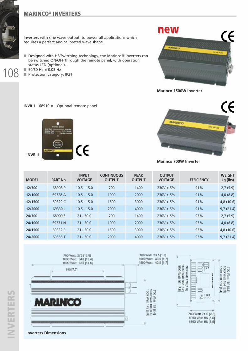
108
INVERTERS
INPUT CONTINUOUS PEAK OUTPUT WEIGHT MODEL PART No. VOLTAGE OUTPUT OUTPUT VOLTAGE EFFICIENCY kg (lbs)
12/700 68908 P 10.5 - 15.0 700 1400 230V ± 5% 91% 2,7 (5.9)
12/1000 69328 A 10.5 - 15.0 1000 2000 230V ± 5% 91% 4,0 (8.8)
12/1500 69329 C 10.5 - 15.0 1500 3000 230V ± 5% 91% 4,8 (10.6)
12/2000 69330 L 10.5 - 15.0 2000 4000 230V ± 5% 91% 9,7 (21.4)
24/700 68909 S 21 - 30.0 700 1400 230V ± 5% 93% 2,7 (5.9)
24/1000 69331 N 21 - 30.0 1000 2000 230V ± 5% 93% 4,0 (8.8)
24/1500 69332 R 21 - 30.0 1500 3000 230V ± 5% 93% 4,8 (10.6)
24/2000 69333 T 21 - 30.0 2000 4000 230V ± 5% 93% 9,7 (21.4)
Inverters with sine wave output, to power all applications whichrequires a perfect and calibrated wave shape.
� Designed with HF/Switching technology, the Marinco® inverters canbe switched ON/OFF through the remote panel, with operationstatus LED (optional).
� 50/60 Hz ± 0.03 Hz� Protection category: IP21
INVR-1 - 68910 A - Optional remote panel
MARINCO® INVERTERS
Marinco 700W Inverter
Marinco 1500W Inverter
INVR-1
Inverters Dimensions
new new
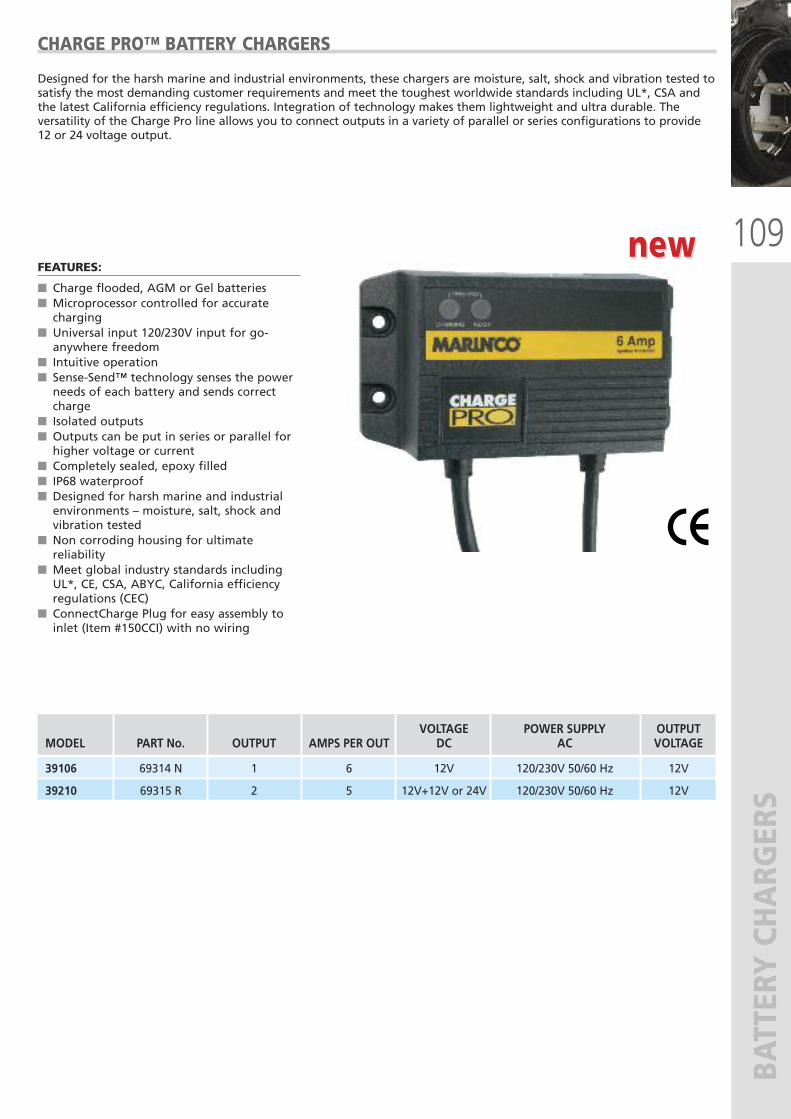
109
BATTERY CHARG
ERS
VOLTAGE POWER SUPPLY OUTPUT MODEL PART No. OUTPUT AMPS PER OUT DC AC VOLTAGE
39106 69314 N 1 6 12V 120/230V 50/60 Hz 12V
39210 69315 R 2 5 12V+12V or 24V 120/230V 50/60 Hz 12V
new new
Designed for the harsh marine and industrial environments, these chargers are moisture, salt, shock and vibration tested tosatisfy the most demanding customer requirements and meet the toughest worldwide standards including UL*, CSA andthe latest California efficiency regulations. Integration of technology makes them lightweight and ultra durable. Theversatility of the Charge Pro line allows you to connect outputs in a variety of parallel or series configurations to provide12 or 24 voltage output.
CHARGE PRO™ BATTERY CHARGERS
FEATURES:
� Charge flooded, AGM or Gel batteries � Microprocessor controlled for accuratecharging
� Universal input 120/230V input for go-anywhere freedom
� Intuitive operation � Sense-Send™ technology senses the powerneeds of each battery and sends correctcharge
� Isolated outputs � Outputs can be put in series or parallel forhigher voltage or current
� Completely sealed, epoxy filled � IP68 waterproof � Designed for harsh marine and industrialenvironments – moisture, salt, shock andvibration tested
� Non corroding housing for ultimatereliability
� Meet global industry standards includingUL*, CE, CSA, ABYC, California efficiencyregulations (CEC)
� ConnectCharge Plug for easy assembly toinlet (Item #150CCI) with no wiring
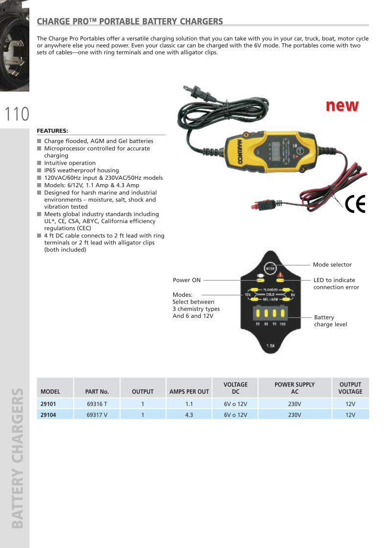
110
BATTERY CHARG
ERS
new new
The Charge Pro Portables offer a versatile charging solution that you can take with you in your car, truck, boat, motor cycleor anywhere else you need power. Even your classic car can be charged with the 6V mode. The portables come with twosets of cables—one with ring terminals and one with alligator clips.
CHARGE PRO™ PORTABLE BATTERY CHARGERS
FEATURES:
� Charge flooded, AGM and Gel batteries � Microprocessor controlled for accuratecharging
� Intuitive operation � IP65 weatherproof housing � 120VAC/60Hz input & 230VAC/50Hz models � Models: 6/12V, 1.1 Amp & 4.3 Amp � Designed for harsh marine and industrialenvironments – moisture, salt, shock andvibration tested
� Meets global industry standards includingUL*, CE, CSA, ABYC, California efficiencyregulations (CEC)
� 4 ft DC cable connects to 2 ft lead with ringterminals or 2 ft lead with alligator clips(both included)
VOLTAGE POWER SUPPLY OUTPUT MODEL PART No. OUTPUT AMPS PER OUT DC AC VOLTAGE
29101 69316 T 1 1.1 6V o 12V 230V 12V
29104 69317 V 1 4.3 6V o 12V 230V 12V
Modes:Select between 3 chemistry types And 6 and 12V Battery
charge level
LED to indicateconnection error
Power ON
Mode selector
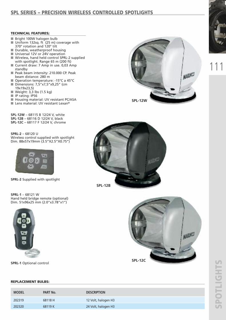
111
SPOTLIGHTS
SPL-12C
SPL-12B
TECHNICAL FEATURES;
� Bright 100W halogen bulb� Uniform 132sq. ft (25 m) coverage with370° rotation and 120° tilt
� Durable, weatherproof housing� Universal 12V or 24V operation� Wireless, hand held control SPRL-2 suppliedwith spotlight. Range 65 m (200 ft)
� Current draw: 7 Amp in use. 0,03 Ampstandby
� Peak beam intensity: 210.000 CP. Peakbeam distance: 280 m
� Operation temperature: -15°C a 45°C� Dimensions: 7,5”x7,5”x9,25” (cm19x19x23,5)
� Weight: 3,3 lbs (1.5 kg)� IP rating: IP56� Housing material: UV resistant PC/ASA� Lens material: UV resistant Lexan®
SPL-12W – 68115 B 12/24 V, whiteSPL-12B – 68116 D 12/24 V, blackSPL-12C – 68117 F 12/24 V, chrome
SPRL-2 – 68120 UWireless control supplied with spotlightDim. 88x57x19mm (3.5”X2.5”X0.75”)
SPRL-2 Supplied with spotlight
SPRL-1 – 68121 WHand held bridge remote (optional)Dim. 51x96x25 mm (2.0”x3.78”x1”)
SPRL-1 Optional control
REPLACEMENT BULBS:
SPL SERIES – PRECISION WIRELESS CONTROLLED SPOTLIGHTS
MODEL PART No. DESCRIPTION
202319 68118 H 12 Volt, halogen H3
202320 68119 K 24 Volt, halogen H3
SPL-12W
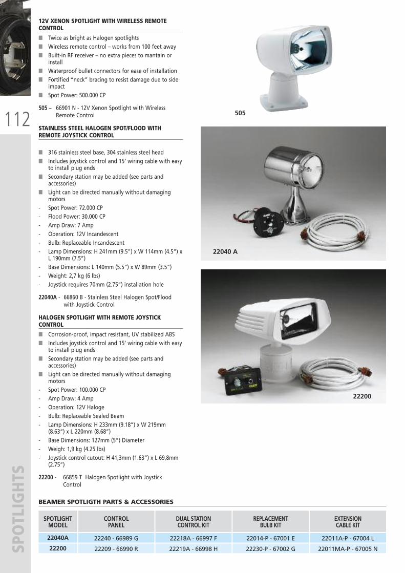
112
SPOTLIGHTS
12V XENON SPOTLIGHT WITH WIRELESS REMOTECONTROL
� Twice as bright as Halogen spotlights� Wireless remote control – works from 100 feet away� Built-in RF receiver – no extra pieces to mantain or
install� Waterproof bullet connectors for ease of installation� Fortified “neck” bracing to resist damage due to side
impact� Spot Power: 500.000 CP
505 – 66901 N - 12V Xenon Spotlight with WirelessRemote Control
STAINLESS STEEL HALOGEN SPOT/FLOOD WITHREMOTE JOYSTICK CONTROL
� 316 stainless steel base, 304 stainless steel head� Includes joystick control and 15’ wiring cable with easy
to install plug ends� Secondary station may be added (see parts and
accessories)� Light can be directed manually without damaging
motors- Spot Power: 72.000 CP- Flood Power: 30.000 CP- Amp Draw: 7 Amp- Operation: 12V Incandescent- Bulb: Replaceable Incandescent- Lamp Dimensions: H 241mm (9.5”) x W 114mm (4.5”) x
L 190mm (7.5”)- Base Dimensions: L 140mm (5.5”) x W 89mm (3.5”)- Weight: 2,7 kg (6 lbs)- Joystick requires 70mm (2.75”) installation hole
22040A - 66860 B - Stainless Steel Halogen Spot/Floodwith Joystick Control
HALOGEN SPOTLIGHT WITH REMOTE JOYSTICKCONTROL
� Corrosion-proof, impact resistant, UV stabilized ABS� Includes joystick control and 15’ wiring cable with easy
to install plug ends� Secondary station may be added (see parts and
accessories)� Light can be directed manually without damaging
motors- Spot Power: 100.000 CP- Amp Draw: 4 Amp- Operation: 12V Haloge- Bulb: Replaceable Sealed Beam- Lamp Dimensions: H 233mm (9.18”) x W 219mm
(8.63”) x L 220mm (8.68”)- Base Dimensions: 127mm (5”) Diameter- Weigh: 1,9 kg (4.25 lbs)- Joystick control cutout: H 41,3mm (1.63”) x L 69,8mm
(2.75”)
22200 - 66859 T Halogen Spotlight with Joystick Control
BEAMER SPOTLIGTH PARTS & ACCESSORIES
22040 A
22200
505
SPOTLIGHTMODEL
22040A
22200
CONTROLPANEL
22240 - 66989 G
22209 - 66990 R
DUAL STATIONCONTROL KIT
22218A - 66997 F
22219A - 66998 H
REPLACEMENTBULB KIT
22014-P - 67001 E
22230-P - 67002 G
EXTENSIONCABLE KIT
22011A-P - 67004 L
22011MA-P - 67005 N
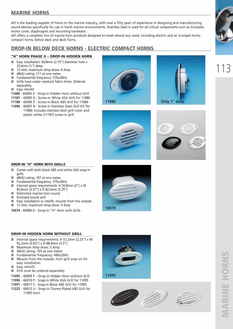
113
MARINE HORN
S
“H” HORN PHASE II – DROP-IN HIDDEN HORN
� Easy installation: 69,8mm (2.75”) diameter hole x25,4mm (1”) deep
� 12 Volt, maximum Amp draw: 4 Amp� dB(A) rating: 111 at one meter� Fundamental frequency: 370±20Hz� Grills have water resistant fabric liners. Ordered
separately.� Easy retrofit11080 - 66904 V - Drop-in Hidden Horn without Grill11187 - 66905 X - Screw-in White ASA Grill for 1108011188 - 66906 Z - Screw-in Black ABS Grill for 1108011096 - 66907 B - Screw-in Stainless Steel Grill Kit for
11080: includes stainless steel grill cover andplastic white (11187) screw-in grill
DROP-IN “H” HORN WITH GRILLS
� Comes with both black ABS and white ASA snap-ingrills
� dB(A) rating: 107 at one meter� Fundamental frequency: 370±20Hz� Internal space requirements: H 50,8mm (2”) x W
85,6mm (3.37”) x D 82,5mm (3.25”)� Distinctive marine horn sound� Enclosed sound unit� Easy installation or retofit, mounts from the outside� 12 Volt, maximum Amp draw: 4 Amp
10079 - 66908 D - Drop-in “H” Horn with Grills
DROP-IN HIDDEN HORN WITHOUT GRILL
� Internal space requirements: H 57,2mm (2.25”) x W92,2mm (3.63”) x D 88,9mm (3.5”)
� Maximum Amp draw: 3 Amp� dB(A) rating: 105 at one meter� Fundamental frequency: 440±20Hz� Mounts from the outside, horn grill snap on for
easy installation� Easy retrofit� Grill must be ordered separately
11095 - 66909 F – Drop-in Hidden Horn without Grill11090 - 66910 P - Snap-in White ASA Grill for 1109511091 - 66911 S - Snap-in Black ABS Grill for 1109511225 - 66912 U - Snap-in Chome Plated ABS Grill for
11095 horn
MARINE HORNS
AFI is the leading supplier of horns to the marine industry, with over a fifty years of experience in designing and manufacturingsound devices specifically for use in harsh marine environments. Stainless steel is used for all critical components such as trumpets,motor cover, diaphragms and mounting hardware.AFI offers a complete line of marine horn products designed to meet almost any need, including electric and air trumpet horns,compact horns, below deck and deck horns.
DROP-IN BELOW DECK HORNS - ELECTRIC COMPACT HORNS
11080 Only 1’’ deep
10079
11095
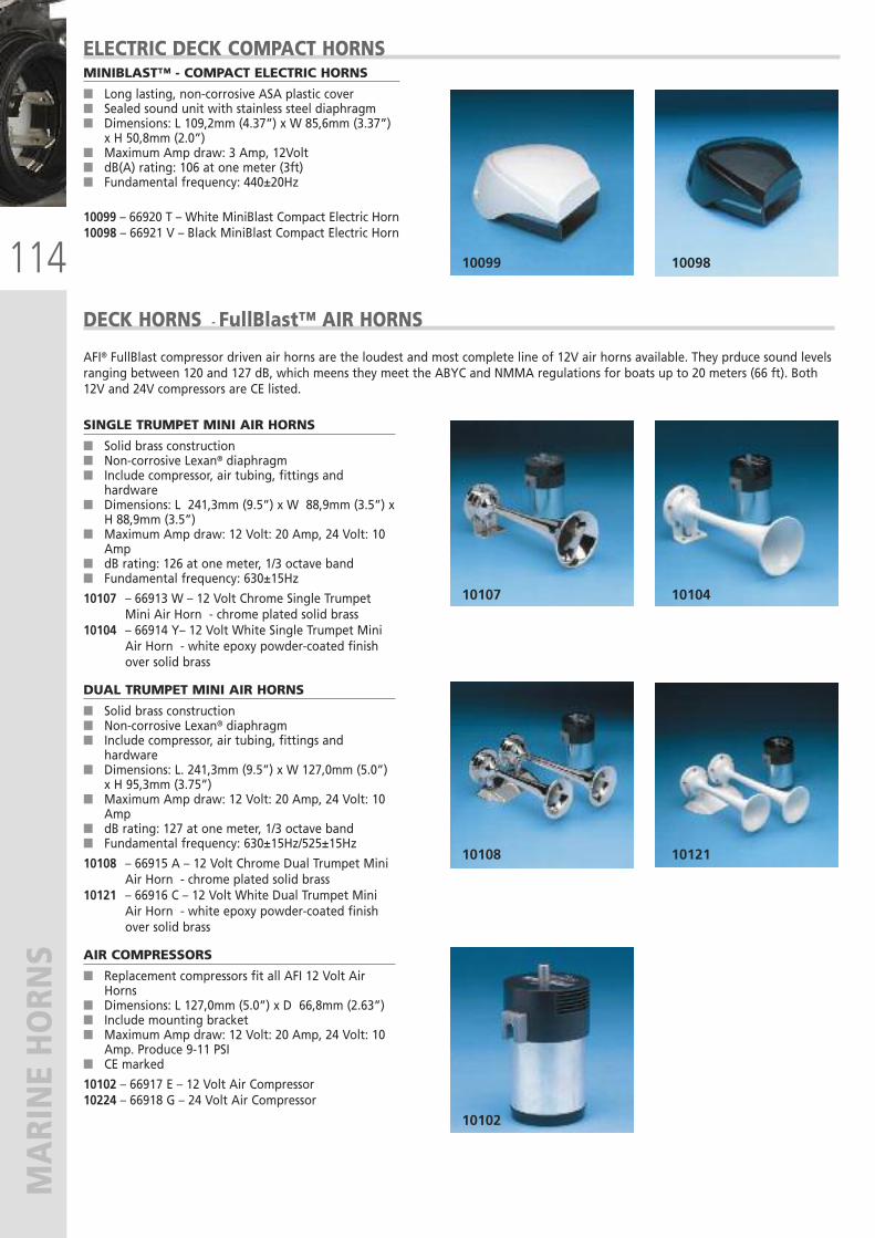
114
MARINE HORN
S
SINGLE TRUMPET MINI AIR HORNS
� Solid brass construction� Non-corrosive Lexan® diaphragm� Include compressor, air tubing, fittings and
hardware� Dimensions: L 241,3mm (9.5”) x W 88,9mm (3.5”) x
H 88,9mm (3.5”)� Maximum Amp draw: 12 Volt: 20 Amp, 24 Volt: 10
Amp� dB rating: 126 at one meter, 1/3 octave band� Fundamental frequency: 630±15Hz
10107 – 66913 W – 12 Volt Chrome Single TrumpetMini Air Horn - chrome plated solid brass
10104 – 66914 Y– 12 Volt White Single Trumpet MiniAir Horn - white epoxy powder-coated finishover solid brass
DUAL TRUMPET MINI AIR HORNS
� Solid brass construction� Non-corrosive Lexan® diaphragm� Include compressor, air tubing, fittings and
hardware� Dimensions: L. 241,3mm (9.5”) x W 127,0mm (5.0”)
x H 95,3mm (3.75”)� Maximum Amp draw: 12 Volt: 20 Amp, 24 Volt: 10
Amp� dB rating: 127 at one meter, 1/3 octave band� Fundamental frequency: 630±15Hz/525±15Hz
10108 – 66915 A – 12 Volt Chrome Dual Trumpet MiniAir Horn - chrome plated solid brass
10121 – 66916 C – 12 Volt White Dual Trumpet MiniAir Horn - white epoxy powder-coated finishover solid brass
AIR COMPRESSORS
� Replacement compressors fit all AFI 12 Volt AirHorns
� Dimensions: L 127,0mm (5.0”) x D 66,8mm (2.63”)� Include mounting bracket� Maximum Amp draw: 12 Volt: 20 Amp, 24 Volt: 10
Amp. Produce 9-11 PSI� CE marked
10102 – 66917 E – 12 Volt Air Compressor10224 – 66918 G – 24 Volt Air Compressor
10107 10104
10108
10102
10121
10099 10098
DECK HORNS - FullBlast™ AIR HORNS
AFI® FullBlast compressor driven air horns are the loudest and most complete line of 12V air horns available. They prduce sound levelsranging between 120 and 127 dB, which meens they meet the ABYC and NMMA regulations for boats up to 20 meters (66 ft). Both12V and 24V compressors are CE listed.
ELECTRIC DECK COMPACT HORNSMINIBLAST™ - COMPACT ELECTRIC HORNS
� Long lasting, non-corrosive ASA plastic cover� Sealed sound unit with stainless steel diaphragm� Dimensions: L 109,2mm (4.37”) x W 85,6mm (3.37”)
x H 50,8mm (2.0”)� Maximum Amp draw: 3 Amp, 12Volt� dB(A) rating: 106 at one meter (3ft)� Fundamental frequency: 440±20Hz
10099 – 66920 T – White MiniBlast Compact Electric Horn10098 – 66921 V – Black MiniBlast Compact Electric Horn
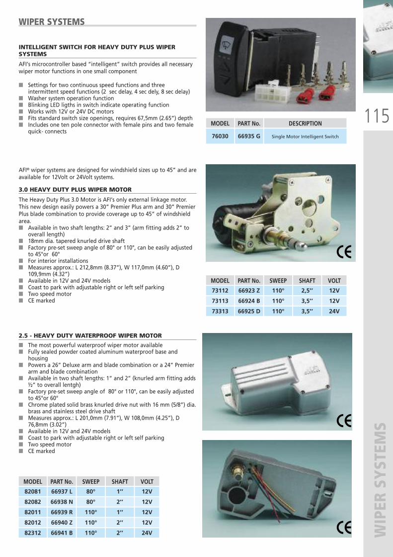
115
WIPER SYSTEM
S
INTELLIGENT SWITCH FOR HEAVY DUTY PLUS WIPERSYSTEMS
AFI’s microcontroller based “intelligent” switch provides all necessarywiper motor functions in one small component
� Settings for two continuous speed functions and threeintermittent speed functions (2 sec delay, 4 sec dely, 8 sec delay)
� Washer system operation function� Blinking LED ligths in switch indicate operating function� Works with 12V or 24V DC motors� Fits standard switch size openings, requires 67,5mm (2.65”) depth� Includes one ten pole connector with female pins and two female
quick- connects
2.5 - HEAVY DUTY WATERPROOF WIPER MOTOR
� The most powerful waterproof wiper motor available� Fully sealed powder coated aluminum waterproof base and
housing� Powers a 26” Deluxe arm and blade combination or a 24” Premier
arm and blade combination� Available in two shaft lengths: 1” and 2” (knurled arm fitting adds
½” to overall lentgh)� Factory pre-set sweep angle of 80° or 110°, can be easily adjusted
to 45°or 60° � Chrome plated solid brass knurled drive nut with 16 mm (5/8”) dia.
brass and stainless steel drive shaft� Measures approx.: L 201,0mm (7.91”), W 108,0mm (4.25”), D
76,8mm (3.02”)� Available in 12V and 24V models� Coast to park with adjustable right or left self parking� Two speed motor� CE marked
MODEL
82081
82082
82011
82012
PART No.
66937 L
66938 N
66939 R
66940 Z
SWEEP
80°
80°
110°
110°
SHAFT
1’’
2’’
1’’
2’’
VOLT
12V
12V
12V
12V
82312 66941 B 110° 2’’ 24V
MODEL
76030
PART No.
66935 G
DESCRIPTION
Single Motor Intelligent Switch
AFI® wiper systems are designed for windshield sizes up to 45” and areavailable for 12Volt or 24Volt systems.
3.0 HEAVY DUTY PLUS WIPER MOTOR
The Heavy Duty Plus 3.0 Motor is AFI’s only external linkage motor.This new design easily powers a 30” Premier Plus arm and 30” PremierPlus blade combination to provide coverage up to 45” of windshieldarea.� Available in two shaft lengths: 2” and 3” (arm fitting adds 2” to
overall length)� 18mm dia. tapered knurled drive shaft� Factory pre-set sweep angle of 80° or 110°, can be easily adjusted
to 45°or 60° � For interior installations� Measures approx.: L 212,8mm (8.37”), W 117,0mm (4.60”), D
109,9mm (4.32”)� Available in 12V and 24V models� Coast to park with adjustable right or left self parking� Two speed motor� CE marked
WIPER SYSTEMS
MODEL
73112
73113
73313
PART No.
66923 Z
66924 B
66925 D
SWEEP
110°
110°
110°
SHAFT
2,5’’
3,5’’
3,5’’
VOLT
12V
12V
24V
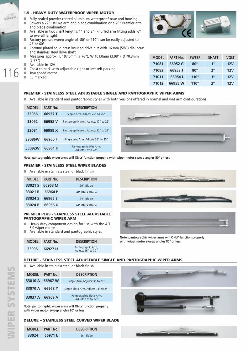
116
WIPER SYSTEM
S1.5 - HEAVY DUTY WATERPROOF WIPER MOTOR
� Fully sealed powder coated aluminum waterproof base and housing� Powers a 22” Deluxe arm and blade combination or a 20” Premier arm
and blade combination� Available in two shaft lengths: 1” and 2” (knurled arm fitting adds ½”
to overall lentgh)� Factory pre-set sweep angle of 80° or 110°, can be easily adjusted to
45°or 60° � Chrome plated solid brass knurled drive nut with 16 mm (5/8”) dia. brass
and stainless steel drive shaft� Measures approx.: L 197,0mm (7.76”), W 101,0mm (3.98”), D 70,3mm
(2.77”)� Available in 12V � Coast to park with adjustable right or left self parking� Two speed motor� CE marked
MODEL
71081
71082
71011
71012
PART No.
66952 G
66953 J
66954 L
66955 W
SWEEP
80°
80°
110°
110°
SHAFT
1’’
2’’
1’’
2’’
VOLT
12V
12V
12V
12V
PREMIER - STAINLESS STEEL ADJUSTABLE SINGLE AND PANTOGRAPHIC WIPER ARMS
� Available in standard and pantographic styles with both versions offered in normal and wet arm configurations
Note: pantographic wiper arms will ONLY function properly with wiper motor sweep angles 80° or less
MODEL
33086
33092
33094
33086W
PART No.
66957 T
66958 V
66959 X
66960 F
DESCRIPTION
Single Arm, Adjusts 20" to 25"
Pantographic Arm, Adjusts 17" to 22"
Pantographic Arm, Adjusts 22" to 26"
Single Wet Arm, Adjusts 20" to 25"
33092W 66961 H Pantographic Wet Arm,Adjusts 17"to 22"
PREMIER - STAINLESS STEEL WIPER BLADES
� Available in stainless steel or black finish
MODEL
33021 S
33021 B
PART No.
66963 M
66964 P
DESCRIPTION
20” Blade
20” Black Blade
33024 S
33024 B
66965 S
66966 U
24” Blade
24” Black Blade
PREMIER PLUS - STAINLESS STEEL ADJUSTABLEPANTOGRAPHIC WIPER ARM� Heavy duty component design for use with the AFI
3.0 wiper motor� Available in standard and pantographic styles
MODEL
33096
PART No.
66927 H
DESCRIPTIONPantographic Arm, Adjusts 26” to 30”
Note: pantographic wiper arms will ONLY function properlywith wiper motor sweep angles 80° or less
DELUXE - STAINLESS STEEL ADJUSTABLE SINGLE AND PANTOGRAPHIC WIPER ARMS
� Available in stainless steel or black finish
Note: pantographic wiper arms will ONLY function properly with wiper motor sweep angles 80° or less
MODEL
33010 A
33070 A
33037 A
PART No.
66967 W
66968 Y
66969 A
DESCRIPTION
Single Arm, Adjusts 14" to 20"
Single Black Arm, Adjusts 18" to 24"
Pantographic Black Arm,Adjusts 17" to 22"
DELUXE – STAINLESS STEEL CURVED WIPER BLADE
MODEL
33024
PART No.
66971 L
DESCRIPTION
26” Blade
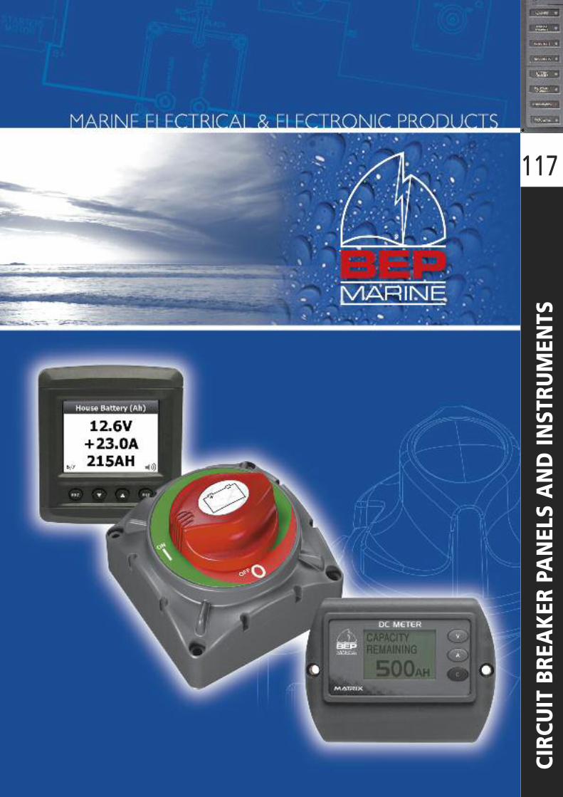
117
CIRCUIT BREAKER PANELS AND IN
STRUMENTS
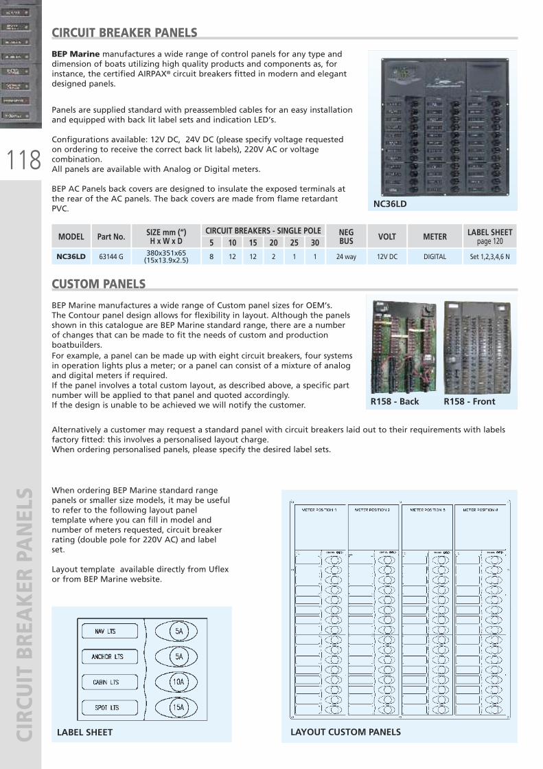
118
CIRCUIT BREAKER PANELS
CIRCUIT BREAKER PANELS
BEP Marine manufactures a wide range of control panels for any type anddimension of boats utilizing high quality products and components as, forinstance, the certified AIRPAX® circuit breakers fitted in modern and elegantdesigned panels.
CUSTOM PANELS
BEP Marine manufactures a wide range of Custom panel sizes for OEM’s.The Contour panel design allows for flexibility in layout. Although the panelsshown in this catalogue are BEP Marine standard range, there are a numberof changes that can be made to fit the needs of custom and productionboatbuilders. For example, a panel can be made up with eight circuit breakers, four systemsin operation lights plus a meter; or a panel can consist of a mixture of analogand digital meters if required.If the panel involves a total custom layout, as described above, a specific partnumber will be applied to that panel and quoted accordingly.If the design is unable to be achieved we will notify the customer.
Panels are supplied standard with preassembled cables for an easy installationand equipped with back lit label sets and indication LED’s.
Configurations available: 12V DC, 24V DC (please specify voltage requestedon ordering to receive the correct back lit labels), 220V AC or voltagecombination. All panels are available with Analog or Digital meters.
BEP AC Panels back covers are designed to insulate the exposed terminals atthe rear of the AC panels. The back covers are made from flame retardantPVC. NC36LD
380x351x65(15x13.9x2.5) 128 2NC36LD 12 1 1 24 way 12V DC DIGITAL Set 1,2,3,4,6 N63144 G
Alternatively a customer may request a standard panel with circuit breakers laid out to their requirements with labelsfactory fitted: this involves a personalised layout charge.When ordering personalised panels, please specify the desired label sets.
When ordering BEP Marine standard rangepanels or smaller size models, it may be usefulto refer to the following layout paneltemplate where you can fill in model andnumber of meters requested, circuit breakerrating (double pole for 220V AC) and labelset.
Layout template available directly from Uflexor from BEP Marine website.
LABEL SHEET LAYOUT CUSTOM PANELS
R158 - Back R158 - Front
SIZE mm (“)H x W x D 155 20
MODEL10
CIRCUIT BREAKERS - SINGLE POLE25 30
NEGBUS VOLT METER LABEL SHEET
page 120Part No.
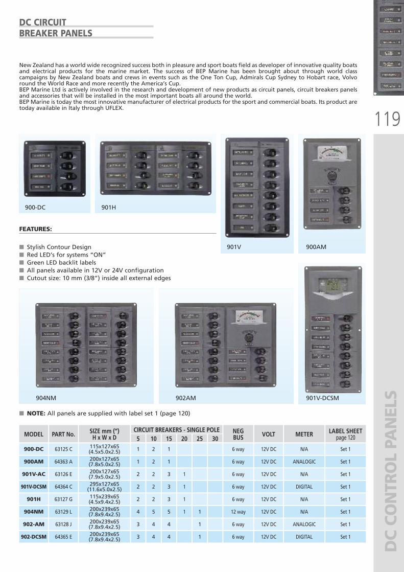
119
DC CONTROL PANELS
DC CIRCUITBREAKER PANELS
New Zealand has a world wide recognized success both in pleasure and sport boats field as developer of innovative quality boatsand electrical products for the marine market. The success of BEP Marine has been brought about through world classcampaigns by New Zealand boats and crews in events such as the One Ton Cup, Admirals Cup Sydney to Hobart race, Volvoround the World Race and more recently the America’s Cup.BEP Marine Ltd is actively involved in the research and development of new products as circuit panels, circuit breakers panelsand accessories that will be installed in the most important boats all around the world. BEP Marine is today the most innovative manufacturer of electrical products for the sport and commercial boats. Its product aretoday available in Italy through UFLEX.
FEATURES:
� Stylish Contour Design� Red LED’s for systems “ON”� Green LED backlit labels� All panels available in 12V or 24V configuration� Cutout size: 10 mm (3/8”) inside all external edges
900-DC
901V
901V-DCSM
900AM
901H
904NM 902AM
� NOTE: All panels are supplied with label set 1 (page 120)
SIZE mm (“)H x W x D 15115x127x65(4.5x5.0x2.5) 1
200x127x65(7.9x5.0x2.5) 3
115x239x65(4.5x9.4x2.5) 3
200x239x65(7.8x9.4x2.5) 5
5
1
2
2
4
20
1
1
1
MODEL
900-DC
901V-AC
901H
904NM
10CIRCUIT BREAKERS - SINGLE POLE
2
2
2
5
200x239x65(7.8x9.4x2.5) 43
25
1
30
1
NEGBUS
6 way
6 way
6 way
12 way
6 way
VOLT
12V DC
12V DC
12V DC
12V DC
12V DC
METER
N/A
N/A
N/A
N/A
ANALOGIC
LABEL SHEETpage 120
Set 1
Set 1
295x127x65(11.6x5.0x2.5) 32 1901V-DCSM 2 6 way 12V DC DIGITAL Set 1
200x127x65(7.8x5.0x2.5) 11900AM 2 6 way 12V DC ANALOGIC Set 1
Set 1
Set 1
Set 1902-AM 4
200x239x65(7.8x9.4x2.5) 43 1 6 way 12V DC DIGITAL Set 1902-DCSM
PART No.
63125 C
63126 E
63127 G
63129 L
64364 C
64363 A
63128 J
64365 E 4
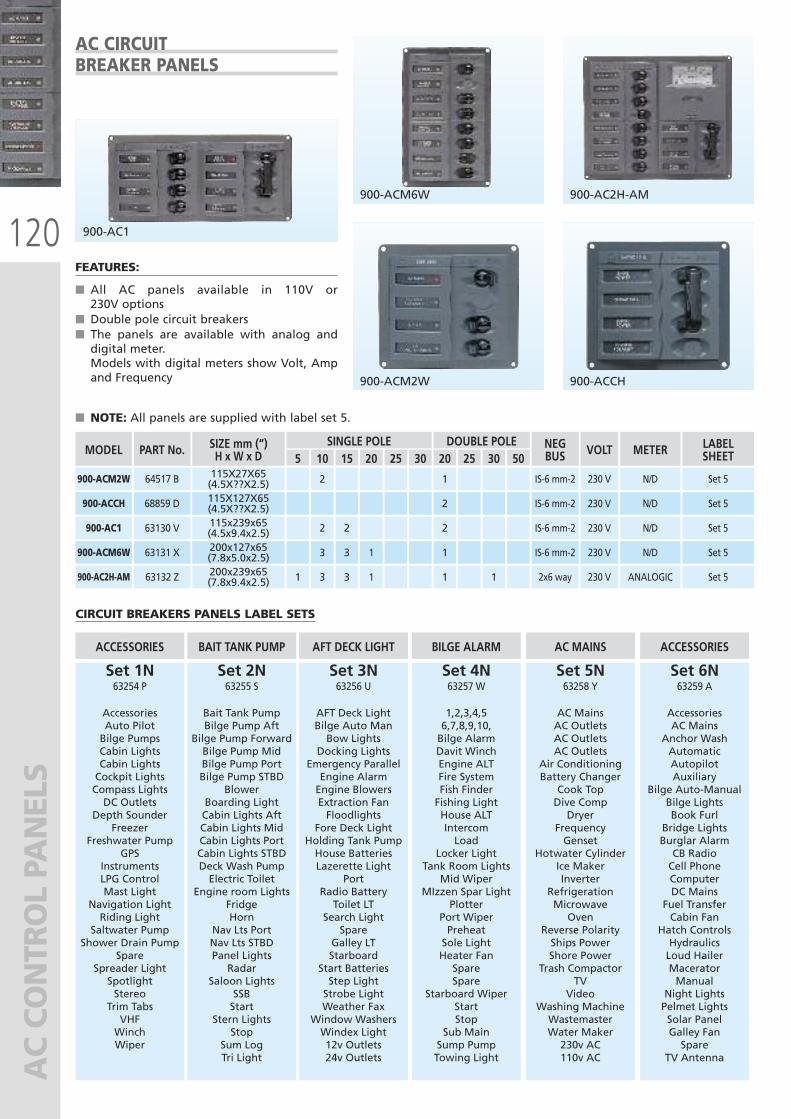
120
AC CONTROL PANELS
AC CIRCUITBREAKER PANELS
CIRCUIT BREAKERS PANELS LABEL SETS
Set 1N63254 P
AccessoriesAuto PilotBilge PumpsCabin LightsCabin LightsCockpit LightsCompass LightsDC Outlets
Depth SounderFreezer
Freshwater PumpGPS
InstrumentsLPG ControlMast Light
Navigation LightRiding Light
Saltwater PumpShower Drain Pump
SpareSpreader LightSpotlightStereoTrim TabsVHFWinchWiper
ACCESSORIES
Set 2N63255 S
Bait Tank PumpBilge Pump Aft
Bilge Pump ForwardBilge Pump MidBilge Pump PortBilge Pump STBD
BlowerBoarding LightCabin Lights AftCabin Lights MidCabin Lights PortCabin Lights STBDDeck Wash PumpElectric Toilet
Engine room LightsFridgeHorn
Nav Lts PortNav Lts STBDPanel LightsRadar
Saloon LightsSSBStart
Stern LightsStop
Sum LogTri Light
BAIT TANK PUMP
Set 3N63256 U
AFT Deck LightBilge Auto ManBow Lights
Docking LightsEmergency ParallelEngine AlarmEngine BlowersExtraction FanFloodlights
Fore Deck LightHolding Tank PumpHouse BatteriesLazerette Light
PortRadio BatteryToilet LT
Search LightSpare
Galley LTStarboard
Start BatteriesStep LightStrobe LightWeather Fax
Window WashersWindex Light12v Outlets24v Outlets
AFT DECK LIGHT
Set 4N63257 W
1,2,3,4,56,7,8,9,10,Bilge AlarmDavit WinchEngine ALTFire SystemFish FinderFishing LightHouse ALTIntercomLoad
Locker LightTank Room Lights
Mid WiperMIzzen Spar Light
PlotterPort WiperPreheatSole LightHeater FanSpareSpare
Starboard WiperStartStop
Sub MainSump PumpTowing Light
BILGE ALARM
Set 5N63258 Y
AC MainsAC OutletsAC OutletsAC Outlets
Air ConditioningBattery Changer
Cook TopDive CompDryer
FrequencyGenset
Hotwater CylinderIce MakerInverter
RefrigerationMicrowaveOven
Reverse PolarityShips PowerShore Power
Trash CompactorTV
VideoWashing MachineWastemasterWater Maker230v AC110v AC
AC MAINS
Set 6N63259 A
AccessoriesAC Mains
Anchor WashAutomaticAutopilotAuxiliary
Bilge Auto-ManualBilge LightsBook Furl
Bridge LightsBurglar AlarmCB RadioCell PhoneComputerDC Mains
Fuel TransferCabin Fan
Hatch ControlsHydraulicsLoud HailerMaceratorManual
Night LightsPelmet LightsSolar PanelGalley FanSpare
TV Antenna
ACCESSORIES
FEATURES:
� All AC panels available in 110V or230V options
� Double pole circuit breakers� The panels are available with analog anddigital meter.Models with digital meters show Volt, Ampand Frequency
900-AC1
900-ACM6W 900-AC2H-AM
900-ACM2W 900-ACCH
� NOTE: All panels are supplied with label set 5.
SIZE mm (“)H x W x D 15
115x239x65(4.5x9.4x2.5) 2
200x127x65(7.8x5.0x2.5) 3
200x239x65(7.8x9.4x2.5) 3
5
1
20
1
1
MODEL
900-AC1
900-ACM6W
900-AC2H-AM
PART No.
63130 V
63131 X
63132 Z
10SINGLE POLE DOUBLE POLE
2
3
3
25 30 20
2
1
1
25 30
1
50NEGBUS
IS-6 mm-2
IS-6 mm-2
2x6 way
VOLT
230 V
230 V
230 V
METER
N/D
N/D
ANALOGIC
LABELSHEET
Set 5
Set 5
115X27X65(4.5X??X2.5)115X127X65(4.5X??X2.5)
900-ACM2W
900-ACCH
64517 B
68859 D
2 1
2
IS-6 mm-2
IS-6 mm-2
230 V
230 V
N/D
N/D
Set 5
Set 5
Set 5
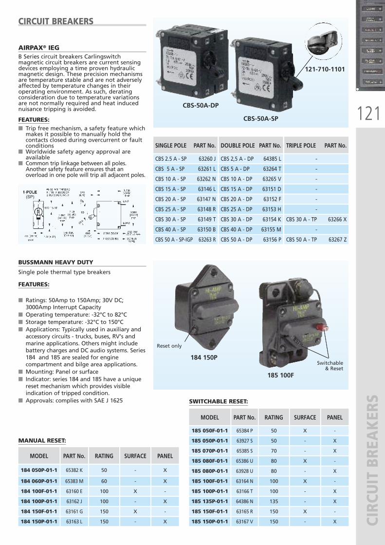
121
CIRCUIT BREAKERS
(SP)
CIRCUIT BREAKERS
AIRPAX® IEGB Series circuit breakers Carlingswitchmagnetic circuit breakers are current sensingdevices employing a time proven hydraulicmagnetic design. These precision mechanismsare temperature stable and are not adverselyaffected by temperature changes in theiroperating environment. As such, deratingconsideration due to temperature variationsare not normally required and heat inducednuisance tripping is avoided.
FEATURES:� Trip free mechanism, a safety feature whichmakes it possible to manually hold thecontacts closed during overcurrent or faultconditions
� Worldwide safety agency approval areavailable
� Common trip linkage between all poles.Another safety feature ensures that anoverload in one pole will trip all adjacent poles.
MANUAL RESET:
SWITCHABLE RESET:
CBS-50A-SP
121-710-1101
CBS-50A-DP
184 150P
185 100F
RATING SURFACEMODEL PANEL
RATING SURFACEMODEL PANEL
Reset only
Switchable& Reset
BUSSMANN HEAVY DUTY
Single pole thermal type breakers
FEATURES:
� Ratings: 50Amp to 150Amp; 30V DC;3000Amp Interrupt Capacity
� Operating temperature: -32°C to 82°C� Storage temperature: -32°C to 150°C� Applications: Typically used in auxiliary andaccessory circuits - trucks, buses, RV’s andmarine applications. Others might includebattery charges and DC audio systems. Series184 and 185 are sealed for enginecompartment and bilge area applications.
� Mounting: Panel or surface� Indicator: series 184 and 185 have a uniquereset mechanism which provides visibleindication of tripped condition.
� Approvals: complies with SAE J 1625
100 X185 100F-01-1 -
150 X185 150F-01-1 -
50 -185 050P-01-1 X
70 -185 070P-01-1 X
80 X185 080F-01-1 -
80 -185 080P-01-1 X
100 -185 100P-01-1 X
135 -185 135P-01-1 X
150 -185 150P-01-1 X
50 X185 050F-01-1
PART No.
63164 N
63165 R
63927 S
65385 S
65386 U
63928 U
63166 T
64386 N
63167 V
65384 P -
100 X184 100F-01-1 -
150 X184 150F-01-1 -
100 -184 100P-01-1 X
150 -184 150P-01-1 X
50 -184 050P-01-1 X
60 -184 060P-01-1
PART No.
63160 E
63161 G
63162 J
63163 L
65382 K
65383 M X
DOUBLE POLE PART No.
CBS 2,5 A - DP 64385 L
TRIPLE POLE PART No.
-
SINGLE POLE PART No.
CBS 2.5 A - SP 63260 J
CBS 5 A - DP 63264 T -CBS 5 A - SP 63261 L
CBS 10 A - DP 63265 V -CBS 10 A - SP 63262 N
CBS 15 A - DP 63151 D -CBS 15 A - SP 63146 L
CBS 20 A - DP 63152 F -CBS 20 A - SP 63147 N
CBS 25 A - DP 63153 H -CBS 25 A - SP 63148 R
CBS 30 A - DP 63154 K CBS 30 A - TP 63266 XCBS 30 A - SP 63149 T
CBS 40 A - DP 63155 M -CBS 40 A - SP 63150 B
CBS 50 A - DP 63156 P CBS 50 A - TP 63267 ZCBS 50 A - SP-IGP 63263 R
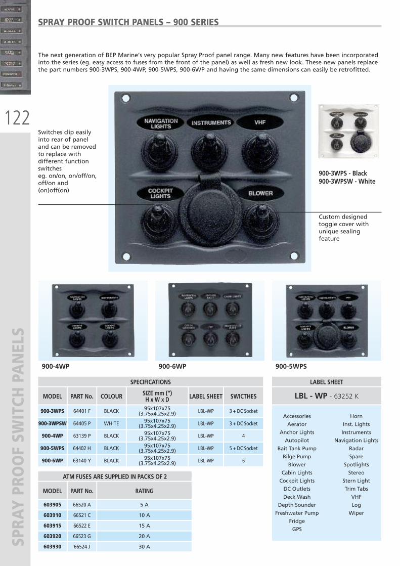
122
SPRAY PRO
OF SW
ITCH PANELS
The next generation of BEP Marine’s very popular Spray Proof panel range. Many new features have been incorporatedinto the series (eg. easy access to fuses from the front of the panel) as well as fresh new look. These new panels replacethe part numbers 900-3WPS, 900-4WP, 900-5WPS, 900-6WP and having the same dimensions can easily be retrofitted.
SPRAY PROOF SWITCH PANELS – 900 SERIES
900-4WP 900-6WP 900-5WPS
Switches clip easily into rear of panel and can be removed to replace withdifferent functionswitches eg. on/on, on/off/on,off/on and(on)off(on)
Custom designedtoggle cover withunique sealingfeature
900-3WPS - Black900-3WPSW - White
LABEL SHEET
LBL - WP - 63252 K
RATING
5 A
15 A
MODEL
ATM FUSES ARE SUPPLIED IN PACKS OF 2
603905
603915
10 A603910
PART No.
66520 A
66522 E
66521 C
30 A603930
20 A603920
66524 J
66523 G
Accessories
Aerator
Anchor Lights
Autopilot
Bait Tank Pump
Bilge Pump
Blower
Cabin Lights
Cockpit Lights
DC Outlets
Deck Wash
Depth Sounder
Freshwater Pump
Fridge
GPS
Horn
Inst. Lights
Instruments
Navigation Lights
Radar
Spare
Spotlights
Stereo
Stern Light
Trim Tabs
VHF
Log
Wiper
MODEL
SPECIFICATIONS
PART No. COLOUR SIZE mm (“)H x W x D LABEL SHEET SWICTHES
900-3WPS 64401 F BLACK 95x107x75(3.75x4.25x2.9) LBL-WP 3 + DC Socket
900-3WPSW 64405 P WHITE 95x107x75(3.75x4.25x2.9) LBL-WP 3 + DC Socket
900-4WP 63139 P BLACK 95x107x75(3.75x4.25x2.9) LBL-WP 4
900-6WP 63140 Y BLACK 95x107x75(3.75x4.25x2.9) LBL-WP 6
900-5WPS 64402 H BLACK 95x107x75(3.75x4.25x2.9) LBL-WP 5 + DC Socket
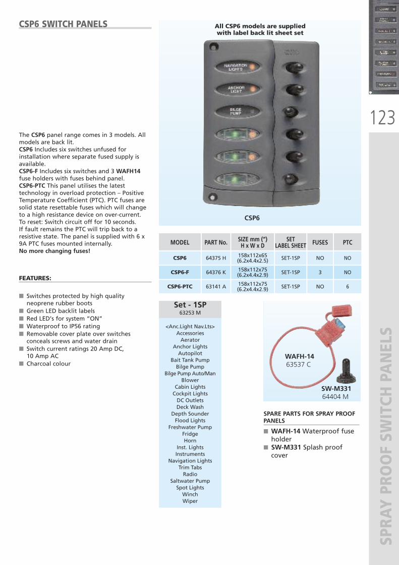
123
SPRAY PRO
OF SW
ITCH PANELS
CSP6 SWITCH PANELS
The CSP6 panel range comes in 3 models. Allmodels are back lit.CSP6 Includes six switches unfused forinstallation where separate fused supply isavailable.CSP6-F Includes six switches and 3 WAFH14fuse holders with fuses behind panel.CSP6-PTC This panel utilises the latesttechnology in overload protection – PositiveTemperature Coefficient (PTC). PTC fuses aresolid state resettable fuses which will changeto a high resistance device on over-current. To reset: Switch circuit off for 10 seconds. If fault remains the PTC will trip back to aresistive state. The panel is supplied with 6 x9A PTC fuses mounted internally. No more changing fuses!
FEATURES:
� Switches protected by high qualityneoprene rubber boots
� Green LED backlit labels� Red LED’s for system “ON”� Waterproof to IP56 rating� Removable cover plate over switchesconceals screws and water drain
� Switch current ratings 20 Amp DC,10 Amp AC
� Charcoal colour
SPARE PARTS FOR SPRAY PROOFPANELS
� WAFH-14 Waterproof fuseholder
� SW-M331 Splash proofcover
SETLABEL SHEET
SET-1SP
FUSES
NO
SIZE mm (“)H x W x D158x112x65(6.2x4.4x2.5)
MODEL
CSP6
PTC
NO
SET-1SP 3158x112x75(6.2x4.4x2.9) CSP6-F NO
SET-1SP NO158x112x75(6.2x4.4x2.9) CSP6-PTC
PART No.
64375 H
64376 K
63141 A 6
CSP6
All CSP6 models are suppliedwith label back lit sheet set
Set - 1SP63253 M
<Anc.Light Nav.Lts>AccessoriesAerator
Anchor LightsAutopilot
Bait Tank PumpBilge Pump
Bilge Pump Auto/ManBlower
Cabin LightsCockpit LightsDC OutletsDeck Wash
Depth SounderFlood Lights
Freshwater PumpFridgeHorn
Inst. LightsInstruments
Navigation LightsTrim TabsRadio
Saltwater PumpSpot LightsWinchWiper
WAFH-14 63537 C
SW-M331 64404 M
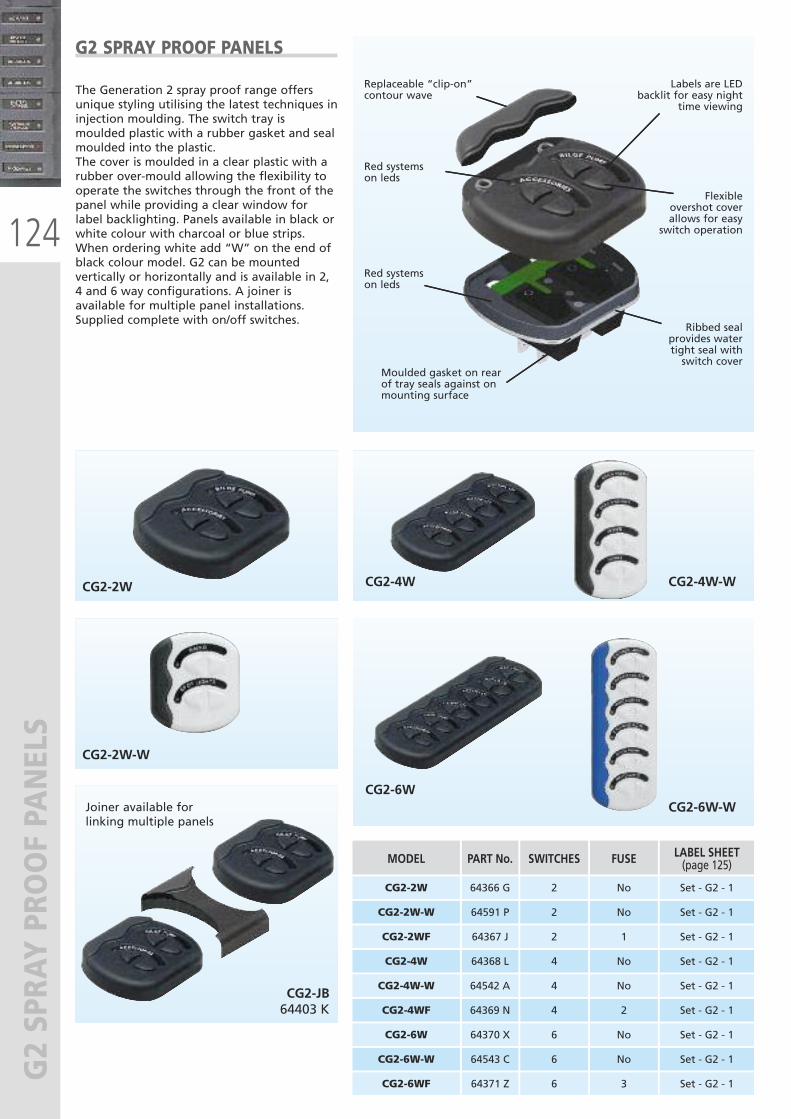
124
G2 SPRAY PRO
OF PANELS
G2 SPRAY PROOF PANELS
The Generation 2 spray proof range offersunique styling utilising the latest techniques ininjection moulding. The switch tray ismoulded plastic with a rubber gasket and sealmoulded into the plastic.The cover is moulded in a clear plastic with arubber over-mould allowing the flexibility tooperate the switches through the front of thepanel while providing a clear window forlabel backlighting. Panels available in black orwhite colour with charcoal or blue strips.When ordering white add “W” on the end ofblack colour model. G2 can be mountedvertically or horizontally and is available in 2,4 and 6 way configurations. A joiner isavailable for multiple panel installations.Supplied complete with on/off switches.
CG2-2W
CG2-2W-W
CG2-4W CG2-4W-W
CG2-6WCG2-6W-W
CG2-JB64403 K
Joiner available for linking multiple panels
CG2-2W
CG2-2W-W
2
2
No
No
Set - G2 - 1
Set - G2 - 1
CG2-2WF
CG2-4W
2
4
1
No
Set - G2 - 1
Set - G2 - 1
CG2-4W-W
CG2-4WF
64366 G
64591 P
64367 J
64368 L
64542 A
64369 N
4
4
No
2
Set - G2 - 1
Set - G2 - 1
CG2-6W
CG2-6W-W
64370 X
64543 C
6
6
No
No
Set - G2 - 1
Set - G2 - 1
CG2-6WF 64371 Z 6 3 Set - G2 - 1
Replaceable “clip-on”contour wave
Red systems on leds
Moulded gasket on rear of tray seals against onmounting surface
Red systems on leds
Labels are LEDbacklit for easy night
time viewing
Flexible overshot coverallows for easy
switch operation
Ribbed seal provides water tight seal with switch cover
MODEL SWITCHES FUSE LABEL SHEET(page 125)PART No.
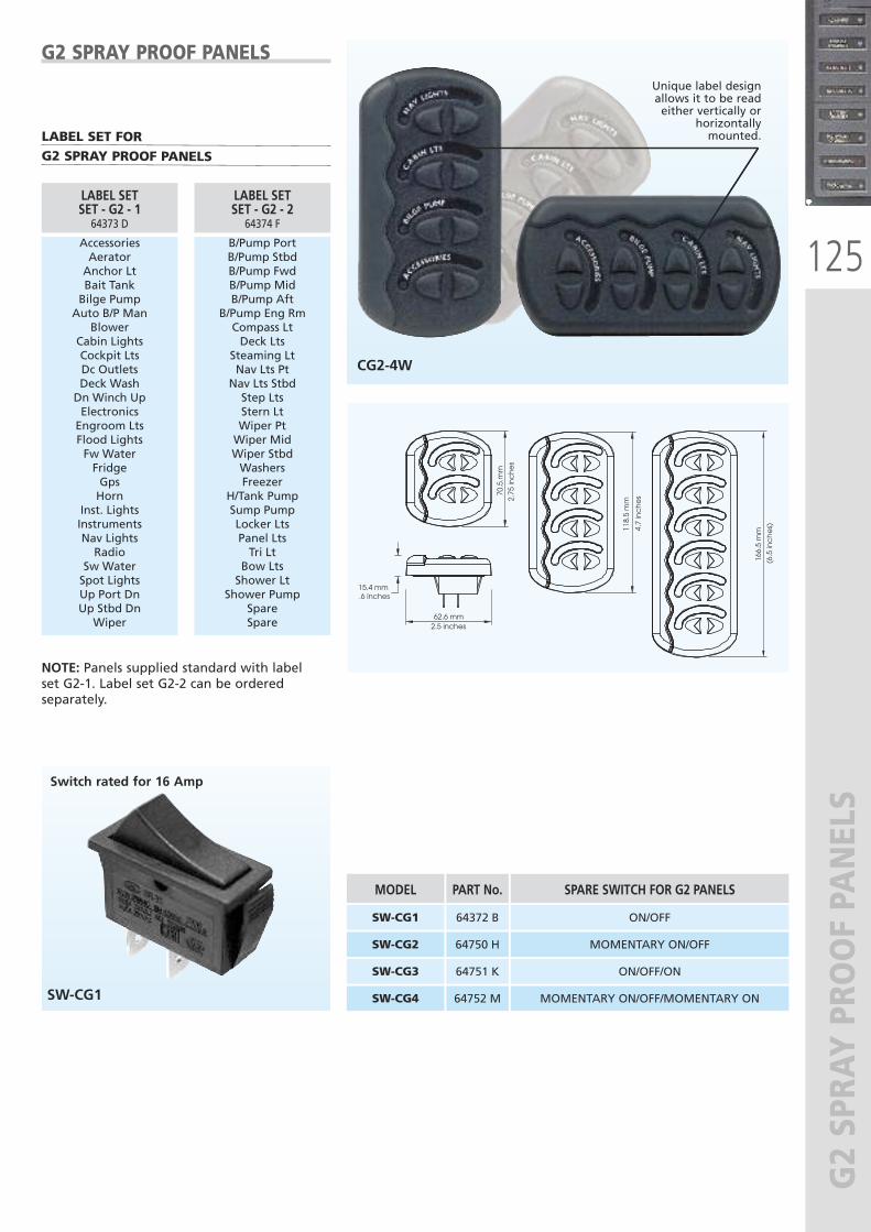
125
G2 SPRAY PRO
OF PANELS
166.
5 m
m
(6.5
inc
he
s)118.
5 m
m
4.7
inc
he
s70.5
.mm
2.75
inc
he
s
15.4 mm .6 inches
62.6 mm 2.5 inches
G2 SPRAY PROOF PANELS
NOTE: Panels supplied standard with label set G2-1. Label set G2-2 can be orderedseparately.
Unique label designallows it to be read either vertically or
horizontally mounted.
CG2-4W
SW-CG1
MODEL
SW-CG1
SPARE SWITCH FOR G2 PANELS
ON/OFF
SW-CG2 MOMENTARY ON/OFF
SW-CG3 ON/OFF/ON
SW-CG4
PART No.
64372 B
64750 H
64751 K
64752 M MOMENTARY ON/OFF/MOMENTARY ON
Switch rated for 16 Amp
LABEL SET FORG2 SPRAY PROOF PANELS
AccessoriesAeratorAnchor LtBait TankBilge PumpAuto B/P Man
BlowerCabin LightsCockpit LtsDc OutletsDeck WashDn Winch UpElectronicsEngroom LtsFlood LightsFw WaterFridgeGpsHorn
Inst. LightsInstrumentsNav LightsRadio
Sw WaterSpot LightsUp Port DnUp Stbd DnWiper
LABEL SETSET - G2 - 164373 D
B/Pump PortB/Pump StbdB/Pump FwdB/Pump MidB/Pump Aft
B/Pump Eng RmCompass LtDeck Lts
Steaming Lt Nav Lts PtNav Lts StbdStep LtsStern LtWiper PtWiper MidWiper StbdWashersFreezer
H/Tank PumpSump PumpLocker LtsPanel LtsTri LtBow LtsShower Lt
Shower PumpSpareSpare
LABEL SETSET - G2 - 264374 F
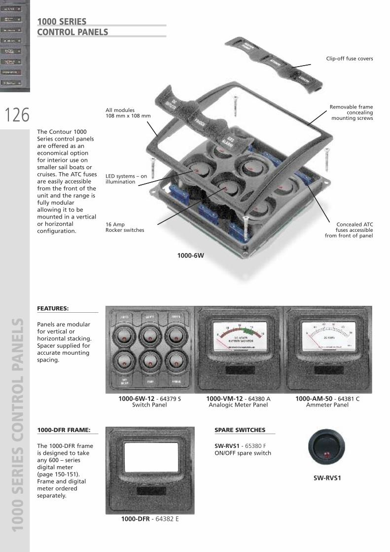
126
1000 SERIES CO
NTROL PANELS
The Contour 1000Series control panelsare offered as aneconomical optionfor interior use onsmaller sail boats orcruises. The ATC fusesare easily accessiblefrom the front of theunit and the range isfully modularallowing it to bemounted in a verticalor horizontalconfiguration.
FEATURES:
Panels are modularfor vertical orhorizontal stacking.Spacer supplied foraccurate mountingspacing.
1000-DFR FRAME:
The 1000-DFR frameis designed to takeany 600 – seriesdigital meter (page 150-151). Frame and digitalmeter orderedseparately.
1000-6W-12 - 64379 SSwitch Panel
1000-DFR - 64382 E
SPARE SWITCHES
SW-RVS1 - 65380 FON/OFF spare switch
SW-RVS1
1000-VM-12 - 64380 AAnalogic Meter Panel
1000-AM-50 - 64381 CAmmeter Panel
All modules108 mm x 108 mm
LED systems – onillumination
16 Amp Rocker switches
Clip-off fuse covers
Removable frameconcealing
mounting screws
Concealed ATC fuses accessible
from front of panel
1000-6W
1000 SERIESCONTROL PANELS
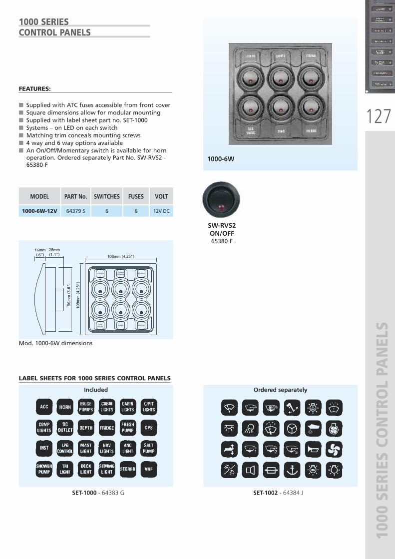
127
1000 SERIES CO
NTROL PANELS
LIGHTSCABIN
STEREO
FANS FRIDGE
LIGHTS
GAS
VALVE
108mm (4.25")
108m
m (
4.25
")
96m
m (
3.8"
)
16mm (.6")
28mm (1.1")
1000 SERIESCONTROL PANELS
1000-6W
SET-1002 - 64384 JSET-1000 - 64383 G
FEATURES:
� Supplied with ATC fuses accessible from front cover� Square dimensions allow for modular mounting� Supplied with label sheet part no. SET-1000� Systems – on LED on each switch� Matching trim conceals mounting screws� 4 way and 6 way options available� An On/Off/Momentary switch is available for hornoperation. Ordered separately Part No. SW-RVS2 -65380 F
LABEL SHEETS FOR 1000 SERIES CONTROL PANELS
Mod. 1000-6W dimensions
6 61000-6W-12V 64379 S 12V DC
Included Ordered separately
SW-RVS2ON/OFF65380 F
SWITCHES FUSESMODEL VOLTPART No.
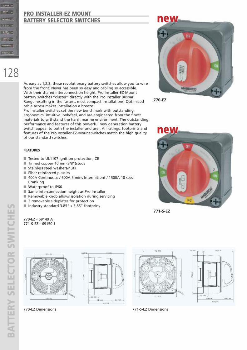
128
BATTERY SELECTOR SW
ITCHES
PRO INSTALLER-EZ MOUNT BATTERY SELECTOR SWITCHES
As easy as 1,2,3, these revolutionary battery switches allow you to wirefrom the front. Never has been so easy and cabling so accessible.With their shared interconnection height, Pro Installer-EZ-Mountbattery switches “cluster” directly with the Pro Installer BusbarRange,resulting in the fastest, most compact installations. Optimizedcable access makes installation a breeze.Pro Installer switches set the new benchmark with outstandingergonomics, intuitive look/feel, and are engineered from the finestmaterials to withstand the harsh marine environment. The outstandingperformance and features of this powerful new generation batteryswitch appeal to both the installer and user. All ratings, footprints andfeatures of the Pro Installer-EZ-Mount switches match the high qualityof our standard switches.
FEATURES
� Tested to UL1107 ignition protection, CE� Tinned copper 10mm (3/8”)studs� Stainless steel washers/nuts� Fiber reinforced plastics� 400A Continuous / 600A 5 mins Intermittent / 1500A 10 secsCranking
� Waterproof to IP66� Same interconnection height as Pro Installer� Removable knob allows isolation during servicing� 3 removable sideplates for protection� Industry standard 3.85” x 3.85” footpriny
770-EZ - 69149 A771-S-EZ - 69150 J
770-EZ
770-EZ Dimensions 771-S-EZ Dimensions
771-S-EZ
new new
new new
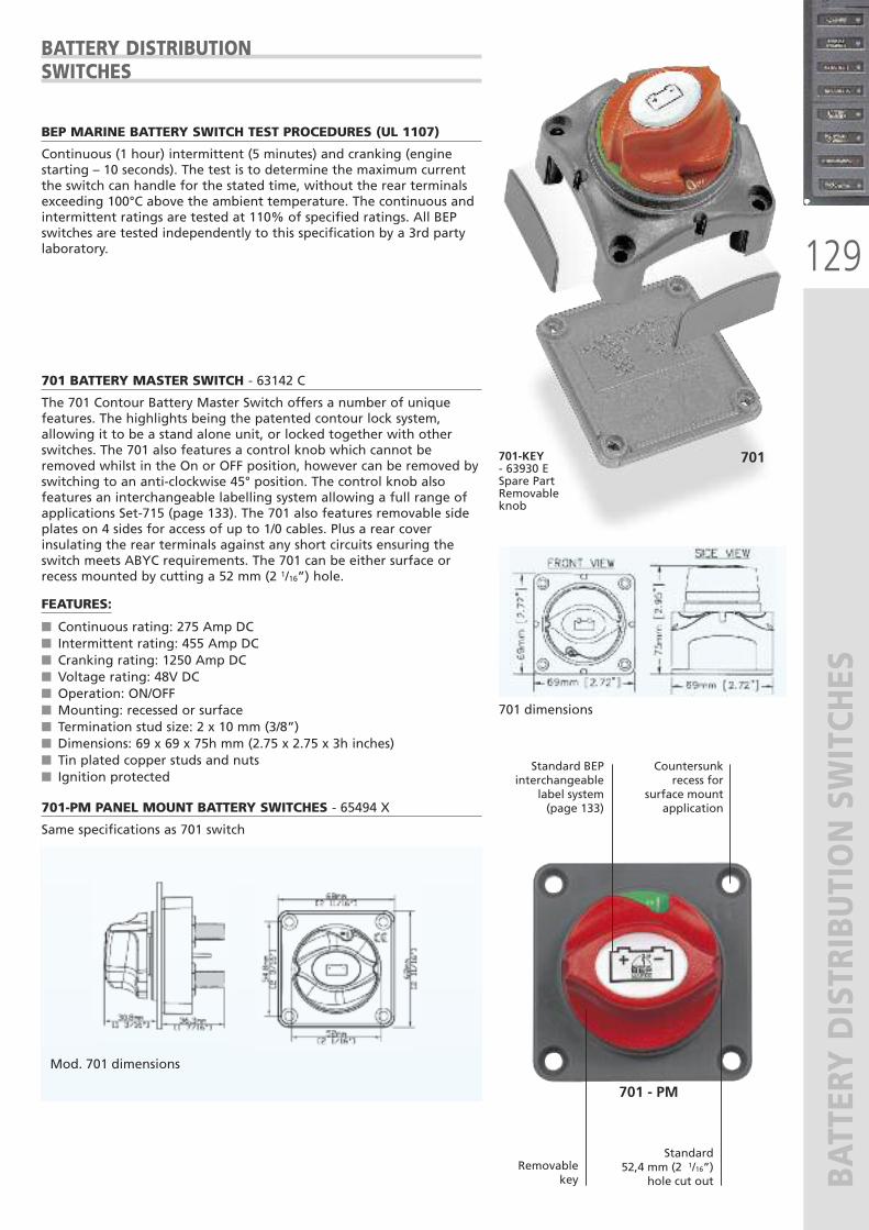
129
BATTERY DISTRIBUTION SWITCHES
BATTERY DISTRIBUTIONSWITCHES
BEP MARINE BATTERY SWITCH TEST PROCEDURES (UL 1107)
Continuous (1 hour) intermittent (5 minutes) and cranking (enginestarting – 10 seconds). The test is to determine the maximum currentthe switch can handle for the stated time, without the rear terminalsexceeding 100°C above the ambient temperature. The continuous andintermittent ratings are tested at 110% of specified ratings. All BEPswitches are tested independently to this specification by a 3rd partylaboratory.
701 BATTERY MASTER SWITCH - 63142 C
The 701 Contour Battery Master Switch offers a number of uniquefeatures. The highlights being the patented contour lock system,allowing it to be a stand alone unit, or locked together with otherswitches. The 701 also features a control knob which cannot beremoved whilst in the On or OFF position, however can be removed byswitching to an anti-clockwise 45° position. The control knob alsofeatures an interchangeable labelling system allowing a full range ofapplications Set-715 (page 133). The 701 also features removable sideplates on 4 sides for access of up to 1/0 cables. Plus a rear coverinsulating the rear terminals against any short circuits ensuring theswitch meets ABYC requirements. The 701 can be either surface orrecess mounted by cutting a 52 mm (2 1/16”) hole.
FEATURES:
� Continuous rating: 275 Amp DC� Intermittent rating: 455 Amp DC� Cranking rating: 1250 Amp DC� Voltage rating: 48V DC� Operation: ON/OFF� Mounting: recessed or surface� Termination stud size: 2 x 10 mm (3/8”)� Dimensions: 69 x 69 x 75h mm (2.75 x 2.75 x 3h inches)� Tin plated copper studs and nuts� Ignition protected
701-PM PANEL MOUNT BATTERY SWITCHES - 65494 X
Same specifications as 701 switch
701
701 - PM
701-KEY- 63930 ESpare PartRemovableknob
701 dimensions
Mod. 701 dimensions
Standard BEP interchangeable
label system(page 133)
Countersunkrecess for
surface mountapplication
Removablekey
Standard 52,4 mm (2 1/16”)
hole cut out
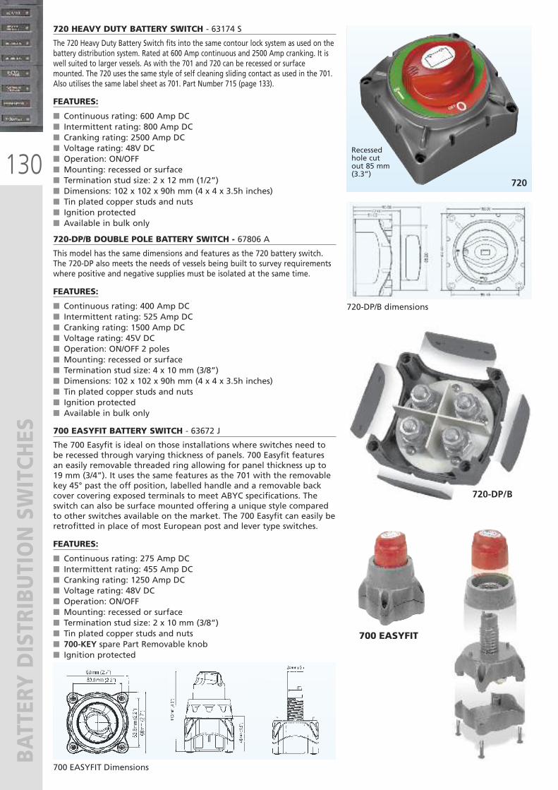
130
BATTERY DISTRIBUTION SWITCHES
720 HEAVY DUTY BATTERY SWITCH - 63174 S
The 720 Heavy Duty Battery Switch fits into the same contour lock system as used on thebattery distribution system. Rated at 600 Amp continuous and 2500 Amp cranking. It iswell suited to larger vessels. As with the 701 and 720 can be recessed or surfacemounted. The 720 uses the same style of self cleaning sliding contact as used in the 701.Also utilises the same label sheet as 701. Part Number 715 (page 133).
FEATURES:
� Continuous rating: 600 Amp DC� Intermittent rating: 800 Amp DC� Cranking rating: 2500 Amp DC� Voltage rating: 48V DC� Operation: ON/OFF� Mounting: recessed or surface� Termination stud size: 2 x 12 mm (1/2”)� Dimensions: 102 x 102 x 90h mm (4 x 4 x 3.5h inches)� Tin plated copper studs and nuts� Ignition protected� Available in bulk only
720
Recessed hole cut out 85 mm(3.3”)
720-DP/B dimensions
720-DP/B DOUBLE POLE BATTERY SWITCH - 67806 A
This model has the same dimensions and features as the 720 battery switch.The 720-DP also meets the needs of vessels being built to survey requirementswhere positive and negative supplies must be isolated at the same time.
FEATURES:
� Continuous rating: 400 Amp DC� Intermittent rating: 525 Amp DC� Cranking rating: 1500 Amp DC� Voltage rating: 45V DC� Operation: ON/OFF 2 poles� Mounting: recessed or surface� Termination stud size: 4 x 10 mm (3/8”)� Dimensions: 102 x 102 x 90h mm (4 x 4 x 3.5h inches)� Tin plated copper studs and nuts� Ignition protected� Available in bulk only
720-DP/B
700 EASYFIT BATTERY SWITCH - 63672 J
The 700 Easyfit is ideal on those installations where switches need tobe recessed through varying thickness of panels. 700 Easyfit featuresan easily removable threaded ring allowing for panel thickness up to19 mm (3/4”). It uses the same features as the 701 with the removablekey 45° past the off position, labelled handle and a removable backcover covering exposed terminals to meet ABYC specifications. Theswitch can also be surface mounted offering a unique style comparedto other switches available on the market. The 700 Easyfit can easily beretrofitted in place of most European post and lever type switches.
FEATURES:
� Continuous rating: 275 Amp DC� Intermittent rating: 455 Amp DC� Cranking rating: 1250 Amp DC� Voltage rating: 48V DC� Operation: ON/OFF� Mounting: recessed or surface� Termination stud size: 2 x 10 mm (3/8”)� Tin plated copper studs and nuts� 700-KEY spare Part Removable knob� Ignition protected
700 EASYFIT Dimensions
700 EASYFIT
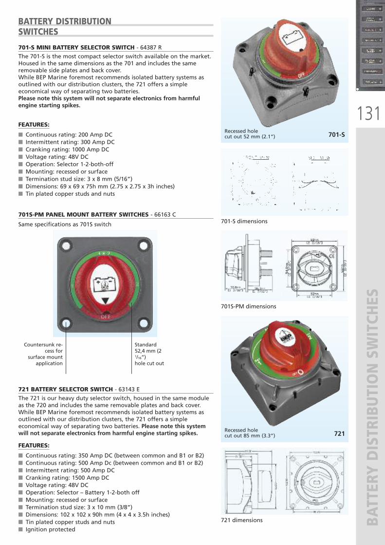
131
BATTERY DISTRIBUTION SWITCHES
701-S MINI BATTERY SELECTOR SWITCH - 64387 R
The 701-S is the most compact selector switch available on the market.Housed in the same dimensions as the 701 and includes the sameremovable side plates and back cover. While BEP Marine foremost recommends isolated battery systems asoutlined with our distribution clusters, the 721 offers a simpleeconomical way of separating two batteries.Please note this system will not separate electronics from harmfulengine starting spikes.
FEATURES:
� Continuous rating: 200 Amp DC� Intermittent rating: 300 Amp DC� Cranking rating: 1000 Amp DC� Voltage rating: 48V DC� Operation: Selector 1-2-both-off� Mounting: recessed or surface� Termination stud size: 3 x 8 mm (5/16”)� Dimensions: 69 x 69 x 75h mm (2.75 x 2.75 x 3h inches)� Tin plated copper studs and nuts
721 BATTERY SELECTOR SWITCH - 63143 E
The 721 is our heavy duty selector switch, housed in the same moduleas the 720 and includes the same removable plates and back cover.While BEP Marine foremost recommends isolated battery systems asoutlined with our distribution clusters, the 721 offers a simpleeconomical way of separating two batteries. Please note this systemwill not separate electronics from harmful engine starting spikes.
FEATURES:
� Continuous rating: 350 Amp DC (between common and B1 or B2)� Continuous rating: 500 Amp Dc (between common and B1 or B2)� Intermittent rating: 500 Amp DC � Cranking rating: 1500 Amp DC� Voltage rating: 48V DC� Operation: Selector – Battery 1-2-both off� Mounting: recessed or surface� Termination stud size: 3 x 10 mm (3/8”)� Dimensions: 102 x 102 x 90h mm (4 x 4 x 3.5h inches)� Tin plated copper studs and nuts� Ignition protected
721Recessed holecut out 85 mm (3.3”)
721 dimensions
701-SRecessed holecut out 52 mm (2.1”)
701-S dimensions
BATTERY DISTRIBUTION SWITCHES
701S-PM PANEL MOUNT BATTERY SWITCHES - 66163 C
Same specifications as 701S switch
701S-PM dimensions
Standard 52,4 mm (21/16”)hole cut out
Countersunk re-cess for
surface mountapplication
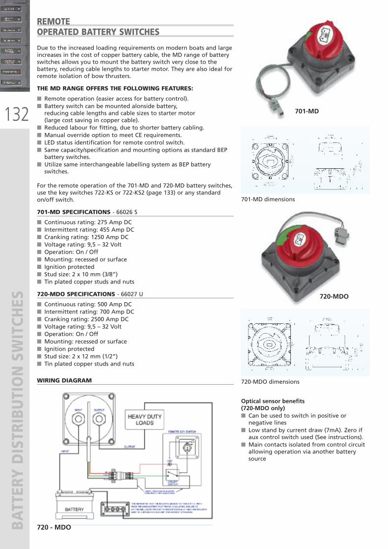
132
BATTERY DISTRIBUTION SWITCHES
Due to the increased loading requirements on modern boats and largeincreases in the cost of copper battery cable, the MD range of batteryswitches allows you to mount the battery switch very close to thebattery, reducing cable lengths to starter motor. They are also ideal forremote isolation of bow thrusters.
THE MD RANGE OFFERS THE FOLLOWING FEATURES:
� Remote operation (easier access for battery control).� Battery switch can be mounted alonside battery, reducing cable lengths and cable sizes to starter motor (large cost saving in copper cable).
� Reduced labour for fitting, due to shorter battery cabling.� Manual override option to meet CE requirements.� LED status identification for remote control switch.� Same capacity/specification and mounting options as standard BEPbattery switches.
� Utilize same interchangeable labelling system as BEP batteryswitches.
For the remote operation of the 701-MD and 720-MD battery switches,use the key switches 722-KS or 722-KS2 (page 133) or any standardon/off switch.
701-MD SPECIFICATIONS - 66026 S
� Continuous rating: 275 Amp DC� Intermittent rating: 455 Amp DC� Cranking rating: 1250 Amp DC � Voltage rating: 9,5 – 32 Volt� Operation: On / Off� Mounting: recessed or surface� Ignition protected� Stud size: 2 x 10 mm (3/8”)� Tin plated copper studs and nuts
720-MDO SPECIFICATIONS - 66027 U
� Continuous rating: 500 Amp DC� Intermittent rating: 700 Amp DC� Cranking rating: 2500 Amp DC � Voltage rating: 9,5 – 32 Volt� Operation: On / Off� Mounting: recessed or surface� Ignition protected� Stud size: 2 x 12 mm (1/2”)� Tin plated copper studs and nuts
720-MDO
701-MD
701-MD dimensions
720-MDO dimensions
REMOTEOPERATED BATTERY SWITCHES
720 - MDO
WIRING DIAGRAM
Optical sensor benefits (720-MDO only)� Can be used to switch in positive ornegative lines
� Low stand by current draw (7mA). Zero ifaux control switch used (See instructions).
� Main contacts isolated from control circuitallowing operation via another batterysource
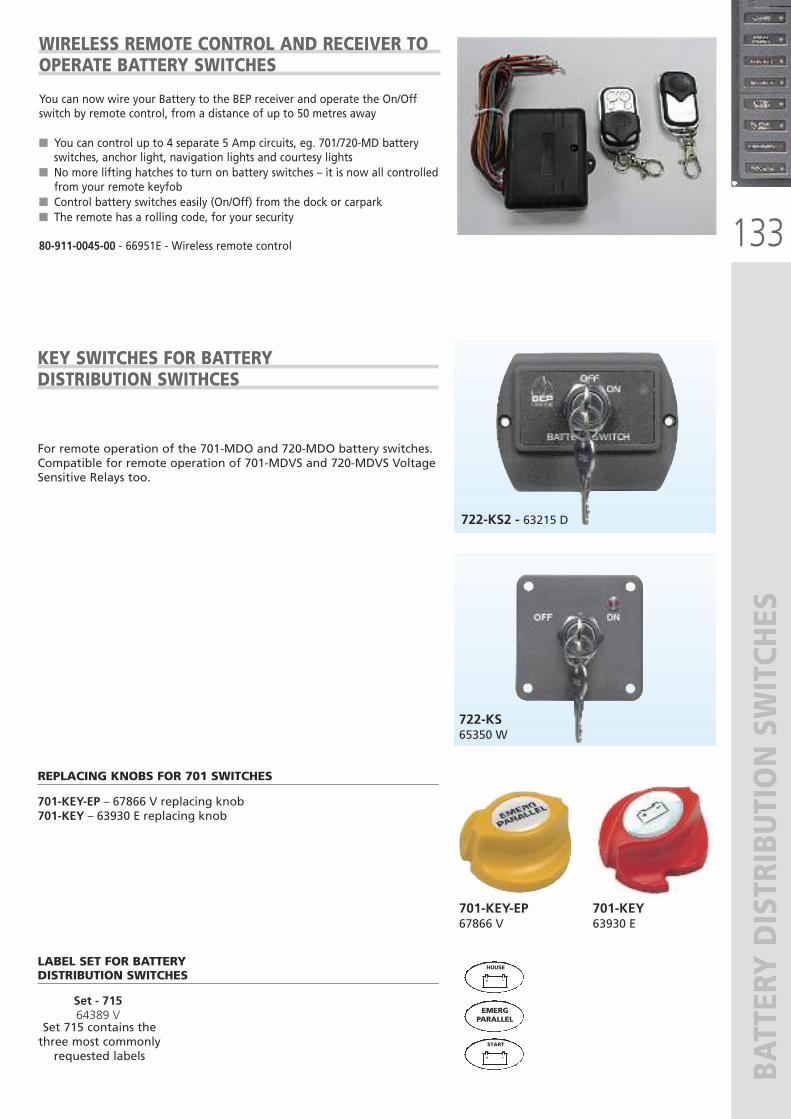
133
BATTERY DISTRIBUTION SWITCHES
KEY SWITCHES FOR BATTERYDISTRIBUTION SWITHCES
722-KS2 - 63215 D
722-KS 65350 W
701-KEY-EP 67866 V
701-KEY63930 E
LABEL SET FOR BATTERYDISTRIBUTION SWITCHES
Set - 715 64389 V
+ -
HOUSE
+ -
START
EMERGPARALLEL
Set 715 contains thethree most commonlyrequested labels
REPLACING KNOBS FOR 701 SWITCHES
701-KEY-EP – 67866 V replacing knob701-KEY – 63930 E replacing knob
For remote operation of the 701-MDO and 720-MDO battery switches.Compatible for remote operation of 701-MDVS and 720-MDVS VoltageSensitive Relays too.
WIRELESS REMOTE CONTROL AND RECEIVER TO OPERATE BATTERY SWITCHES
You can now wire your Battery to the BEP receiver and operate the On/Offswitch by remote control, from a distance of up to 50 metres away
� You can control up to 4 separate 5 Amp circuits, eg. 701/720-MD batteryswitches, anchor light, navigation lights and courtesy lights
� No more lifting hatches to turn on battery switches – it is now all controlledfrom your remote keyfob
� Control battery switches easily (On/Off) from the dock or carpark� The remote has a rolling code, for your security
80-911-0045-00 - 66951E - Wireless remote control
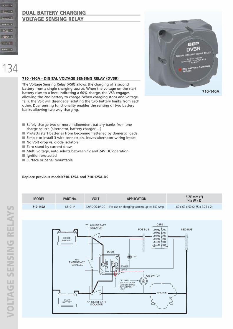
134
VOLTAGE SENSING RELAY
S
� Safely charge two or more indipendent battery banks from onecharge source (alternator, battery charger….)
� Protects start batteries from becoming flattened by domestic loads � Simple to install 3-wire connection, leaves alternator wiring intact� No Volt drop vs. diode isolators� Zero stand by current draw� Multi voltage, auto selects between 12 and 24V DC operation� Ignition protected� Surface or panel mountable
Replace previous models710-125A and 710-125A-DS
710 -140A - DIGITAL VOLTAGE SENSING RELAY (DVSR)
The Voltage Sensing Relay (VSR) allows the charging of a secondbattery from a single charging source. When the voltage on the startbattery rises to a level indicating a 60% charge, the VSR engagesallowing the 2nd battery to charge. When charging stops and voltagefalls, the VSR will disengage isolating the two battery banks from eachother. Dual sensing functionality enables the sensing of two batterybanks allowing two way charging.
DUAL BATTERY CHARGINGVOLTAGE SENSING RELAY
710-140A
APPLICATION
For use on charging systems up to: 140 Amp
MODEL
710-140A
SIZE mm (“)H x W x D
69 x 69 x 50 (2.75 x 2.75 x 2)
PART No.
68101 P
VOLT
12V DC/24V DC
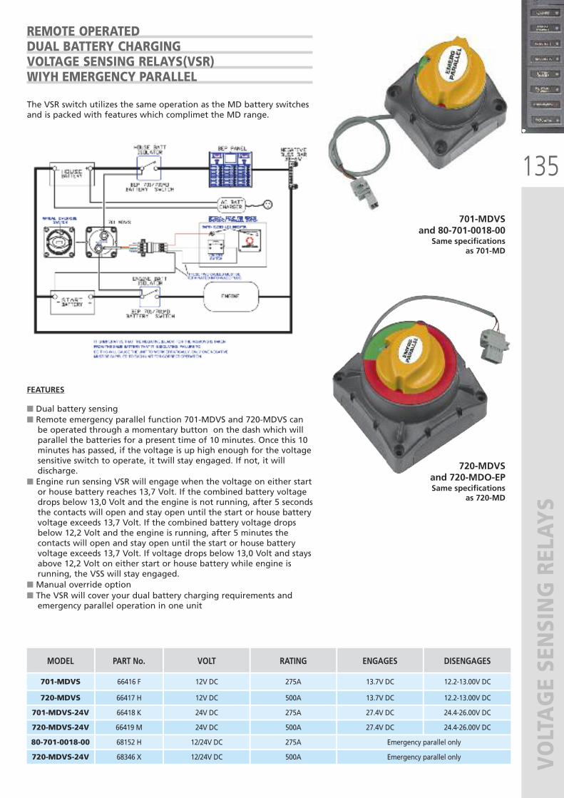
135
VOLTAGE SENSING RELAY
S
The VSR switch utilizes the same operation as the MD battery switchesand is packed with features which complimet the MD range.
FEATURES
� Dual battery sensing� Remote emergency parallel function 701-MDVS and 720-MDVS canbe operated through a momentary button on the dash which willparallel the batteries for a present time of 10 minutes. Once this 10minutes has passed, if the voltage is up high enough for the voltagesensitive switch to operate, it twill stay engaged. If not, it willdischarge.
� Engine run sensing VSR will engage when the voltage on either startor house battery reaches 13,7 Volt. If the combined battery voltagedrops below 13,0 Volt and the engine is not running, after 5 secondsthe contacts will open and stay open until the start or house batteryvoltage exceeds 13,7 Volt. If the combined battery voltage dropsbelow 12,2 Volt and the engine is running, after 5 minutes thecontacts will open and stay open until the start or house batteryvoltage exceeds 13,7 Volt. If voltage drops below 13,0 Volt and staysabove 12,2 Volt on either start or house battery while engine isrunning, the VSS will stay engaged.
� Manual override option� The VSR will cover your dual battery charging requirements andemergency parallel operation in one unit
720-MDVSand 720-MDO-EPSame specifications
as 720-MD
701-MDVSand 80-701-0018-00
Same specifications as 701-MD
MODEL
701-MDVS
720-MDVS
701-MDVS-24V
720-MDVS-24V
PART No.
66416 F
66417 H
66418 K
66419 M
VOLT
12V DC
12V DC
24V DC
24V DC
RATING
275A
500A
275A
500A
ENGAGES
13.7V DC
13.7V DC
27.4V DC
27.4V DC
DISENGAGES
12.2-13.00V DC
12.2-13.00V DC
24.4-26.00V DC
24.4-26.00V DC
80-701-0018-00
720-MDVS-24V
68152 H
68346 X
12/24V DC
12/24V DC
275A
500A
Emergency parallel only
Emergency parallel only
REMOTE OPERATEDDUAL BATTERY CHARGINGVOLTAGE SENSING RELAYS(VSR)WIYH EMERGENCY PARALLEL
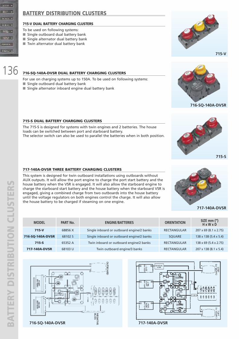
136
BATTERY DISTRIBUTION CLUSTERS
715-V
716-SQ-140A-DVSR
715-S
717-140A-DVSR
715-V DUAL BATTERY CHARGING CLUSTERS
To be used on following systems:� Single outboard dual battery bank� Single alternator dual battery bank� Twin alternator dual battery bank
716-SQ-140A-DVSR DUAL BATTERY CHARGING CLUSTERS
For use on charging systems up to 150A. To be used on following systems:� Single outboard dual battery bank� Single alternator inboard engine dual battery bank
715-S DUAL BATTERY CHARGING CLUSTERS
The 715-S is designed for systems with twin engines and 2 batteries. The houseloads can be switched between port and starboard battery. The selector switch can also be used to parallel the batteries when in both position.
717-140A-DVSR THREE BATTERY CHARGING CLUSTERS
This system is designed for twin outboard installations using outboards withoutAUX outputs. It will allow the port engine to charge the port start battery and thehouse battery when the VSR is engaged. It will also allow the starboard engine tocharge the starboard start battery and the house battery when the starboard VSR isengaged, giving a combined charge from two outboards into the house batteryuntil the voltage regulators on both engines control the charge. It will also allowthe house battery to be charged if steaming on one engine.
BATTERY DISTRIBUTION CLUSTERS
ENGINE/BATTERIES
Single inboard or outboard engine/2 banks
MODEL
716-SQ-140A-DVSR
SIZE mm (“)H x W x D
138 x 138 (5.4 x 5.4)
Twin inboard or outboard engine/2 banks715-S 138 x 69 (5.4 x 2.75)
Twin outboard engine/3 banks
ORIENTATION
SQUARE
RECTANGULAR
RECTANGULAR717-140A-DVSR
PART No.
68102 S
Single inboard or outboard engine/2 banks715-V 207 x 69 (8.1 x 2.75)RECTANGULAR68856 X
65352 A
68103 U 207 x 138 (8.1 x 5.4)
716-SQ-140A-DVSR 717-140A-DVSR
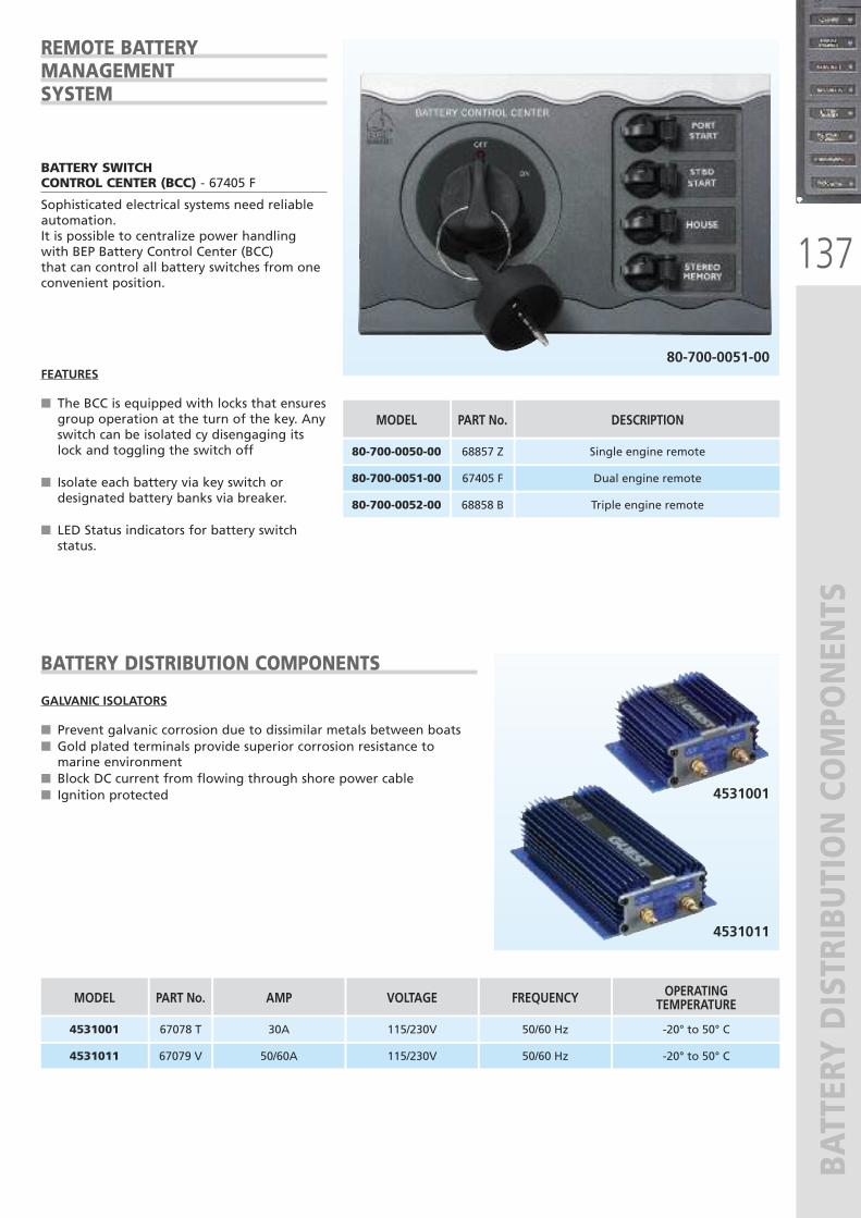
137
BATTERY DISTRIBUTION COMPONENTS
80-700-0051-00
BATTERY SWITCHCONTROL CENTER (BCC) - 67405 F
Sophisticated electrical systems need reliableautomation.It is possible to centralize power handlingwith BEP Battery Control Center (BCC)that can control all battery switches from oneconvenient position.
FEATURES
� The BCC is equipped with locks that ensuresgroup operation at the turn of the key. Anyswitch can be isolated cy disengaging itslock and toggling the switch off
� Isolate each battery via key switch ordesignated battery banks via breaker.
� LED Status indicators for battery switchstatus.
REMOTE BATTERYMANAGEMENTSYSTEM
4531011
4531001
GALVANIC ISOLATORS
� Prevent galvanic corrosion due to dissimilar metals between boats� Gold plated terminals provide superior corrosion resistance tomarine environment
� Block DC current from flowing through shore power cable� Ignition protected
BATTERY DISTRIBUTION COMPONENTS
AMP
30A
MODEL
4531001
VOLTAGE
115/230V
50/60A4531011
PART No.
67078 T
67079 V 115/230V
FREQUENCY
50/60 Hz
OPERATING TEMPERATURE
-20° to 50° C
50/60 Hz -20° to 50° C
DESCRIPTION
Single engine remote
MODEL
80-700-0050-00
Dual engine remote80-700-0051-00
PART No.
68857 Z
67405 F
Triple engine remote80-700-0052-00 68858 B
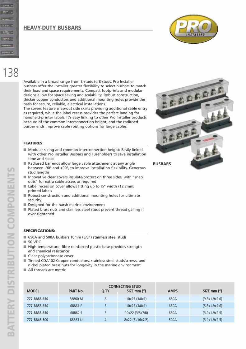
138
BATTERY DISTRIBUTION COMPONENTS
Available in a broad range from 3-studs to 8-studs, Pro Installerbusbars offer the installer greater flexibility to select busbars to matchtheir load and space requirements. Compact footprints and modulardesigns allow for space saving and scalability. Robust construction,thicker copper conductors and additional mounting holes provide thebasis for secure, reliable, electrical installations.The covers feature snap-out side skirts providing additional cable entryas required, while the label recess provides the perfect landing forhandheld-printer labels. It’s easy linking to other Pro Installer productsbecause of the common interconnection height, and the radiusedbusbar ends improve cable routing options for large cables.
FEATURES:
� Modular sizing and common interconnection height: Easily linkedwith other Pro Installer Busbars and Fuseholders to save installationtime and space
� Radiused bar ends allow large cable attachment at any anglebetween -90º and +90º, to improve installation flexibility. Generousstud lengths
� Innovative clear covers insulate/protect on three sides, with “snapouts” for extra cable access as required
� Label recess on cover allows fitting up to ½” width (12.7mm)printed labels
� Robust construction and additional mounting holes for ultimatesecurity
� Designed for the harsh marine environment� Plated brass nuts and stainless steel studs prevent thread galling ifover-tightened
SPECIFICATIONS:
� 650A and 500A busbars 10mm (3/8”) stainless steel studs� 50 VDC� High temperature, fibre reinforced plastic base provides strengthand chemical resistance
� Clear polycarbonate cover� Tinned CDA102 Copper conductors, stainless steel studs/screws, andnickel plated brass nuts for longevity in the marine environment
� All threads are metric
BUSBARS
HEAVY-DUTY BUSBARS
CONNECTING STUDMODEL PART No. Q.TY SIZE mm (“) AMPS SIZE mm (“)
777-BB8S-650 68860 M 8 10x25 (3/8x1) 650A (9.8x1.9x2.6)
777-BB5S-650 68861 P 5 10x25 (3/8x1) 650A (5.8x1.9x2.6)
777-BB3S-650 68862 S 3 10x22 (3/8x7/8) 650A (3.9x1.9x2.5)
777-BB4S-500 68863 U 4 8x22 (5./16x7/8) 500A (3.9x1.9x2.5)
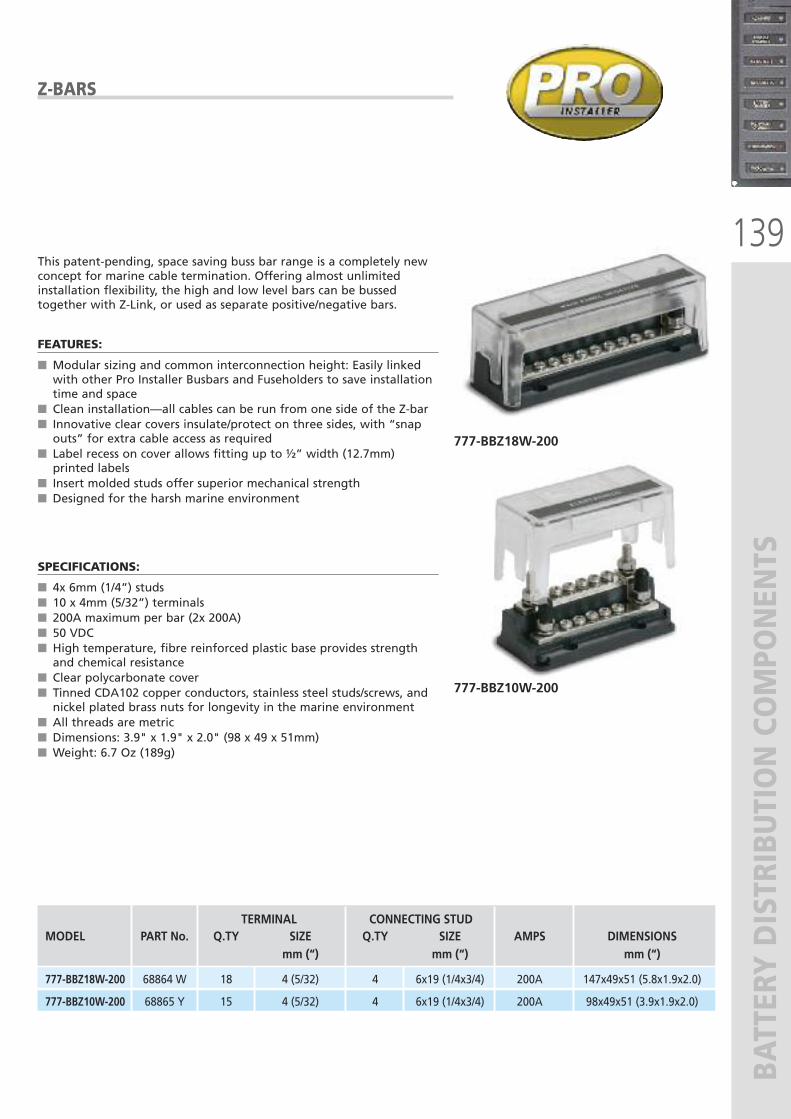
139
BATTERY DISTRIBUTION COMPONENTS
This patent-pending, space saving buss bar range is a completely newconcept for marine cable termination. Offering almost unlimitedinstallation flexibility, the high and low level bars can be bussedtogether with Z-Link, or used as separate positive/negative bars.
FEATURES:
� Modular sizing and common interconnection height: Easily linkedwith other Pro Installer Busbars and Fuseholders to save installationtime and space
� Clean installation—all cables can be run from one side of the Z-bar� Innovative clear covers insulate/protect on three sides, with “snapouts” for extra cable access as required
� Label recess on cover allows fitting up to ½” width (12.7mm)printed labels
� Insert molded studs offer superior mechanical strength� Designed for the harsh marine environment
SPECIFICATIONS:
� 4x 6mm (1/4”) studs� 10 x 4mm (5/32”) terminals� 200A maximum per bar (2x 200A)� 50 VDC� High temperature, fibre reinforced plastic base provides strengthand chemical resistance
� Clear polycarbonate cover� Tinned CDA102 copper conductors, stainless steel studs/screws, andnickel plated brass nuts for longevity in the marine environment
� All threads are metric� Dimensions: 3.9" x 1.9" x 2.0" (98 x 49 x 51mm)� Weight: 6.7 Oz (189g)
777-BBZ18W-200
777-BBZ10W-200
Z-BARS
TERMINAL CONNECTING STUDMODEL PART No. Q.TY SIZE Q.TY SIZE AMPS DIMENSIONS
mm (“) mm (“) mm (“)
777-BBZ18W-200 68864 W 18 4 (5/32) 4 6x19 (1/4x3/4) 200A 147x49x51 (5.8x1.9x2.0)
777-BBZ10W-200 68865 Y 15 4 (5/32) 4 6x19 (1/4x3/4) 200A 98x49x51 (3.9x1.9x2.0)
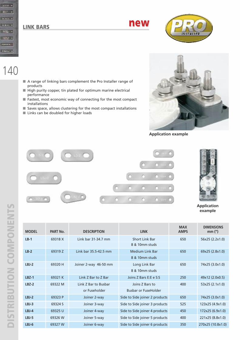
140
DISTRIBUTION COMPONENTS
� A range of linking bars complement the Pro Installer range ofproducts
� High purity copper, tin plated for optimum marine electricalperformance
� Fastest, most economic way of connecting for the most compactinstallations
� Saves space, allows clustering for the most compact installations� Links can be doubled for higher loads
Application example
Applicationexample
LINK BARS
MAX DIMENSIONS MODEL PART No. DESCRIPTION LINK AMPS mm (“)
LB-1 69318 X Link bar 31-34.7 mm Short Link Bar 650 56x25 (2.2x1.0)
8 & 10mm studs
LB-2 69319 Z Link bar 35.5-42.5 mm Medium Link Bar 650 69x25 (2.8x1.0)
8 & 10mm studs
LBJ-2 69320 H Joiner 2-way 46-50 mm Long Link Bar 650 74x25 (3.0x1.0)
8 & 10mm studs
LBZ-1 69321 K Link Z Bar to Z Bar Joins Z Bars E:E e S:S 250 49x12 (2.0x0.5)
LBZ-2 69322 M Link Z Bar to Busbar Joins Z Bars to 400 53x25 (2.1x1.0)
or Fuseholder Busbar or FuseHolder
LBJ-2 69323 P Joiner 2-way Side to Side joiner 2 products 650 74x25 (3.0x1.0)
LBJ-3 69324 S Joiner 3-way Side to Side joiner 3 products 525 123x25 (4.9x1.0)
LBJ-4 69325 U Joiner 4-way Side to Side joiner 4 products 450 172x25 (6.9x1.0)
LBJ-5 69326 W Joiner 5-way Side to Side joiner 5 products 400 221x25 (8.8x1.0)
LBJ-6 69327 W Joiner 6-way Side to Side joiner 6 products 350 270x25 (10.8x1.0)
new new
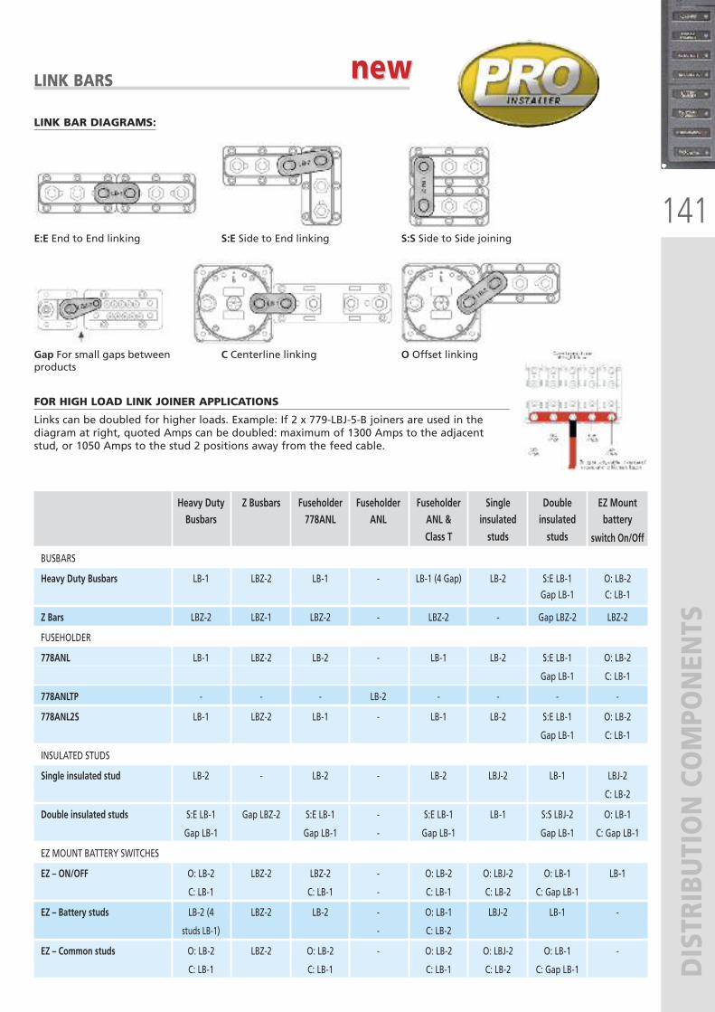
E:E End to End linking S:E Side to End linking S:S Side to Side joining
Gap For small gaps betweenproducts
C Centerline linking O Offset linking
141
DISTRIBUTION COMPONENTS
LINK BARS
FOR HIGH LOAD LINK JOINER APPLICATIONS
Links can be doubled for higher loads. Example: If 2 x 779-LBJ-5-B joiners are used in thediagram at right, quoted Amps can be doubled: maximum of 1300 Amps to the adjacentstud, or 1050 Amps to the stud 2 positions away from the feed cable.
LINK BAR DIAGRAMS:
Heavy Duty Z Busbars Fuseholder Fuseholder Fuseholder Single Double EZ Mount Busbars 778ANL ANL ANL & insulated insulated battery
Class T studs studs switch On/Off
BUSBARS
Heavy Duty Busbars LB-1 LBZ-2 LB-1 - LB-1 (4 Gap) LB-2 S:E LB-1 O: LB-2
Gap LB-1 C: LB-1
Z Bars LBZ-2 LBZ-1 LBZ-2 - LBZ-2 - Gap LBZ-2 LBZ-2
FUSEHOLDER
778ANL LB-1 LBZ-2 LB-2 - LB-1 LB-2 S:E LB-1 O: LB-2
Gap LB-1 C: LB-1
778ANLTP - - - LB-2 - - - -
778ANL2S LB-1 LBZ-2 LB-1 - LB-1 LB-2 S:E LB-1 O: LB-2
Gap LB-1 C: LB-1
INSULATED STUDS
Single insulated stud LB-2 - LB-2 - LB-2 LBJ-2 LB-1 LBJ-2
C: LB-2
Double insulated studs S:E LB-1 Gap LBZ-2 S:E LB-1 - S:E LB-1 LB-1 S:S LBJ-2 O: LB-1
Gap LB-1 Gap LB-1 - Gap LB-1 Gap LB-1 C: Gap LB-1
EZ MOUNT BATTERY SWITCHES
EZ – ON/OFF O: LB-2 LBZ-2 LBZ-2 - O: LB-2 O: LBJ-2 O: LB-1 LB-1
C: LB-1 C: LB-1 - C: LB-1 C: LB-2 C: Gap LB-1
EZ – Battery studs LB-2 (4 LBZ-2 LB-2 - O: LB-1 LBJ-2 LB-1 -
studs LB-1) - C: LB-2
EZ – Common studs O: LB-2 LBZ-2 O: LB-2 - O: LB-2 O: LBJ-2 O: LB-1 -
C: LB-1 C: LB-1 C: LB-1 C: LB-2 C: Gap LB-1
new new
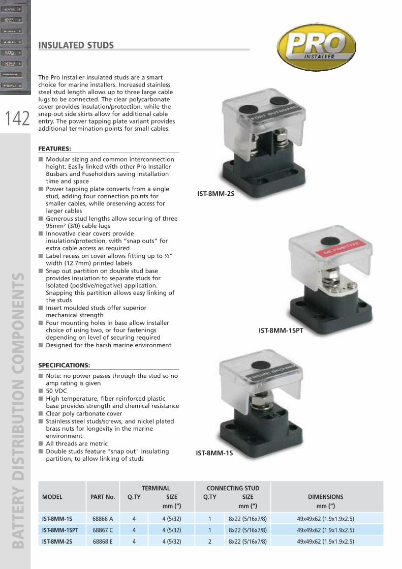
142
BATTERY DISTRIBUTION COMPONENTS
The Pro Installer insulated studs are a smartchoice for marine installers. Increased stainlesssteel stud length allows up to three large cablelugs to be connected. The clear polycarbonatecover provides insulation/protection, while thesnap-out side skirts allow for additional cableentry. The power tapping plate variant providesadditional termination points for small cables.
FEATURES:
� Modular sizing and common interconnectionheight: Easily linked with other Pro InstallerBusbars and Fuseholders saving installationtime and space
� Power tapping plate converts from a singlestud, adding four connection points forsmaller cables, while preserving access forlarger cables
� Generous stud lengths allow securing of three95mm² (3/0) cable lugs
� Innovative clear covers provideinsulation/protection, with “snap outs” forextra cable access as required
� Label recess on cover allows fitting up to ½”width (12.7mm) printed labels
� Snap out partition on double stud baseprovides insulation to separate studs forisolated (positive/negative) application.Snapping this partition allows easy linking ofthe studs
� Insert moulded studs offer superiormechanical strength
� Four mounting holes in base allow installerchoice of using two, or four fasteningsdepending on level of securing required
� Designed for the harsh marine environment
SPECIFICATIONS:
� Note: no power passes through the stud so noamp rating is given
� 50 VDC � High temperature, fiber reinforced plasticbase provides strength and chemical resistance
� Clear poly carbonate cover � Stainless steel studs/screws, and nickel platedbrass nuts for longevity in the marineenvironment
� All threads are metric� Double studs feature "snap out" insulatingpartition, to allow linking of studs
IST-8MM-2S
INSULATED STUDS
IST-8MM-1SPT
IST-8MM-1S
TERMINAL CONNECTING STUDMODEL PART No. Q.TY SIZE Q.TY SIZE DIMENSIONS
mm (“) mm (“) mm (“)
IST-8MM-1S 68866 A 4 4 (5/32) 1 8x22 (5/16x7/8) 49x49x62 (1.9x1.9x2.5)
IST-8MM-1SPT 68867 C 4 4 (5/32) 1 8x22 (5/16x7/8) 49x49x62 (1.9x1.9x2.5)
IST-8MM-2S 68868 E 4 4 (5/32) 2 8x22 (5/16x7/8) 49x49x62 (1.9x1.9x2.5)
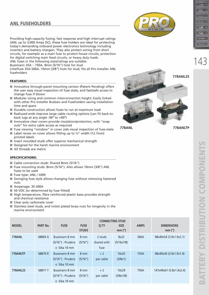
143
BATTERY DISTRIBUTION COMPONENTS
Providing high-capacity fusing, fast response and high interrupt ratings(ANL up to 3,000 Amps DC), these fuse holders are ideal for protectingtoday’s demanding onboard power electronics technology includinginverters and battery chargers. They also protect wiring from shortcircuits, for example as a main fuse to protect house circuits, protectionfor digital switching main feed circuits, or heavy duty loads.ANL fuses in the following sizes/ratings are suitable:Bussmann 35A – 750A. 8mm (5/16”) hole for studLittelfuse 35A-500A. 10mm (3/8”) hole for stud, fits all Pro Installer ANLfuseholders
FEATURES:
� Innovative through-panel mounting version (Patent Pending) offersthe user easy visual inspection of fuse state, and fast/safe access tochange fuse if blown
� Modular sizing and common interconnection height: Easily linkedwith other Pro Installer Busbars and Fuseholders saving installationtime and space
� Durable construction allows fuses to run at maximum load� Radiused ends improve large cable routing options (can fit back-to-back lugs at any angle -90º to +90º)
� Innovative clear covers provide insulation/protection, with “snapouts” for extra cable access as required
� Fuse viewing “window” in cover aids visual inspection of fuse-state� Label recess on cover allows fitting up to ½” width (12.7mm)printed labels
� Insert moulded studs offer superior mechanical strength� Designed for the harsh marine environment� All threads are metric
SPECIFICATIONS:
� Cable connection studs: Shared 8mm (5/16")� Fuse mounting studs: 8mm (5/16”). Also allows 10mm (3/8”) ANLfuses to be used
� Fuse type: ANL / ANN� Swinging fuse style allows changing fuse without removing fastenednuts
� Amperage: 35-300A� 50 VDC (or determined by fuse fitted)� High temperature, fibre reinforced plastic base provides strengthand chemical resistance
� Clear poly carbonate cover� Stainless steel studs, and nickel plated brass nuts for longevity in themarine environment
778ANL 778ANLTP
778ANL2S
ANL FUSEHOLDERS
CONNECTING STUDMODEL PART No. FUSE FUSE Q.TY SIZE AMPS DIMENSIONS
STUDS mm (“) mm (“)
778ANL 68869 G Bussmann 8 mm 8 mm 2 studs 8x22 300A 98x49x54 (3.9x1.9x2.1)
(5/16”) - Prudenz (5/16”) shared with (5/16x7/8)
o Siba 10 mm fuse
778ANLTP 68870 R Bussmann 8 mm 8 mm + 2 10x25 750A 98x49x36 (3.9x1.9x1.4)
(5/16”) - Prudenz (5/16”) per cable (3/8x1)
o Siba 10 mm
778ANL2S 68871 T Bussmann 8 mm 8 mm + 2 10x29 750A 147x49x61 (5.8x1.9x2.4)
(5/16”) - Prudenz (5/16”) per cable (3/8x1/8)
o Siba 10 mm
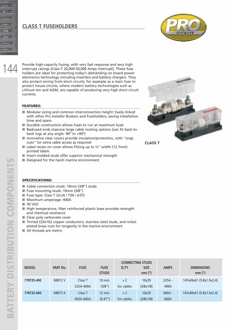
144
BATTERY DISTRIBUTION COMPONENTS
Provide high-capacity fusing, with very fast response and very highinterrupt ratings (Class-T 20,000-50,000 Amps interrupt). These fuseholders are ideal for protecting today’s demanding on board powerelectronics technology including inverters and battery chargers. Theyalso protect wiring from short circuits, for example as a main fuse toprotect house circuits, where modern battery technologies such asLithium Ion and AGM, are capable of producing very high short circuitcurrents.
FEATURES:
� Modular sizing and common interconnection height: Easily linkedwith other Pro Installer Busbars and Fuseholders, saving installationtime and space
� Durable construction allows fuses to run at maximum load� Radiused ends improve large cable routing options (can fit back-to-back lugs at any angle -90º to +90º)
� Innovative clear covers provide insulation/protection, with “snapouts” for extra cable access as required
� Label recess on cover allows fitting up to ½” width (12.7mm)printed labels
� Insert molded studs offer superior mechanical strength� Designed for the harsh marine environment
SPECIFICATIONS:
� Cable connection studs: 10mm (3/8”) studs� Fuse mounting studs: 10mm (3/8”) � Fuse type: Class T (JLLN / TJN / A3T)� Maximum amperage: 400A� 50 VDC� High temperature, fiber reinforced plastic base provides strengthand chemical resistance
� Clear poly carbonate cover� Tinned CDA102 copper conductors, stainless steel studs, and nickelplated brass nuts for longevity in the marine environment
� All threads are metric
CLASS T
CLASS T FUSEHOLDERS
CONNECTING STUDSMODEL PART No. FUSE FUSE Q.TY SIZE AMPS DIMENSIONS
STUDS mm (“) mm (“)
778T2S-400 68872 V Class T 10 mm + 2 10x29 225A - 147x49x61 (5.8x1.9x2.4)
225A-400A (3/8”) for cables (3/8x1/8) 400A
778T2S-600 68873 X Class T 12 mm + 2 10x29 400A - 147x49x61 (5.8x1.9x2.4)
450A-600A (0.47”) for cables (3/8x1/8) 600A
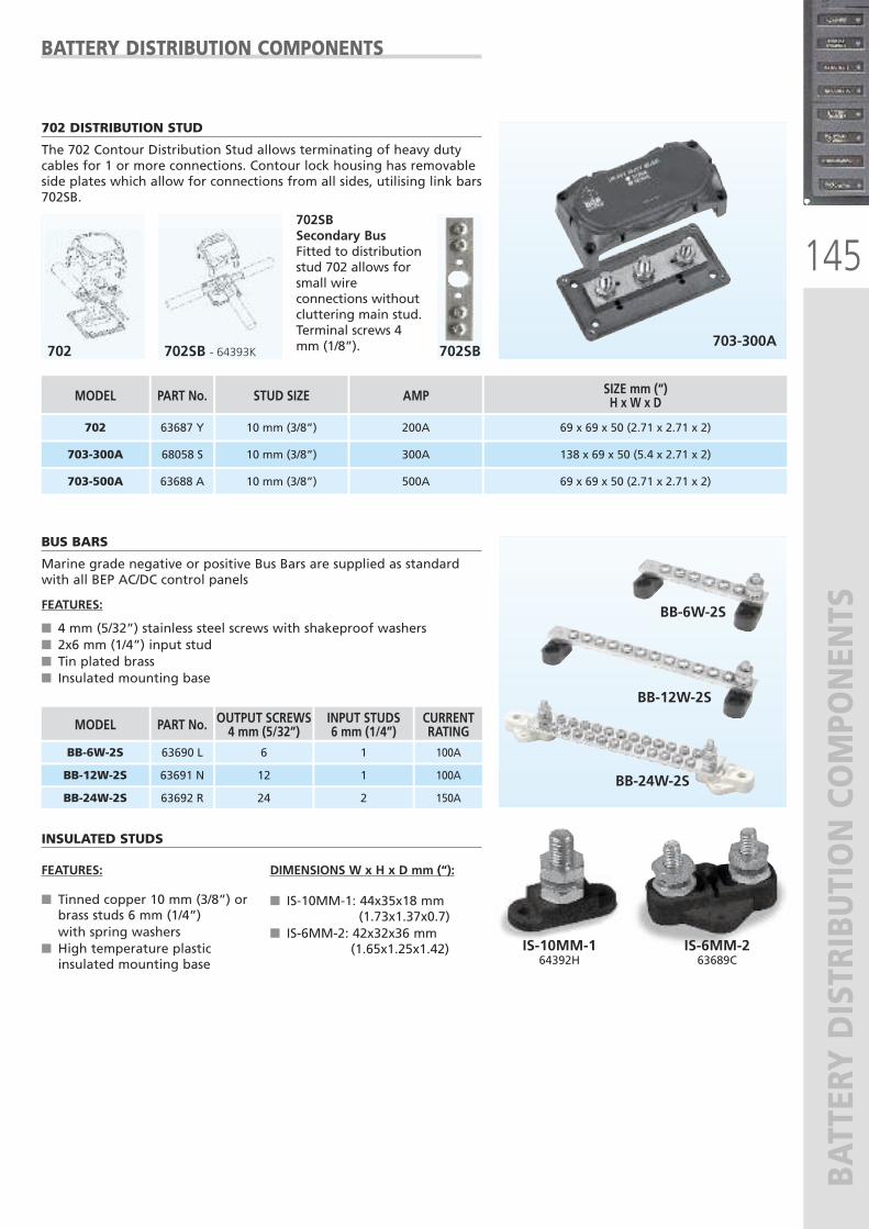
145
BATTERY DISTRIBUTION COMPONENTS
BATTERY DISTRIBUTION COMPONENTS
703-300A
702 DISTRIBUTION STUD
The 702 Contour Distribution Stud allows terminating of heavy dutycables for 1 or more connections. Contour lock housing has removableside plates which allow for connections from all sides, utilising link bars702SB.
702SB
702SBSecondary BusFitted to distributionstud 702 allows forsmall wireconnections withoutcluttering main stud.Terminal screws 4mm (1/8”).702 702SB - 64393K
MODEL
702
SIZE mm (“)H x W x D
69 x 69 x 50 (2.71 x 2.71 x 2)
703-300A
PART No.
63687 Y
68058 S 138 x 69 x 50 (5.4 x 2.71 x 2)
703-500A 63688 A 69 x 69 x 50 (2.71 x 2.71 x 2)
STUD SIZE
10 mm (3/8”)
AMP
200A
10 mm (3/8”)
10 mm (3/8”)
300A
500A
BUS BARS
Marine grade negative or positive Bus Bars are supplied as standardwith all BEP AC/DC control panels
FEATURES:
� 4 mm (5/32”) stainless steel screws with shakeproof washers� 2x6 mm (1/4”) input stud� Tin plated brass� Insulated mounting base
FEATURES:
� Tinned copper 10 mm (3/8”) orbrass studs 6 mm (1/4”)with spring washers
� High temperature plasticinsulated mounting base
DIMENSIONS W x H x D mm (“):
� IS-10MM-1: 44x35x18 mm(1.73x1.37x0.7)
� IS-6MM-2: 42x32x36 mm(1.65x1.25x1.42)
INSULATED STUDS
BB-6W-2S
BB-12W-2S
BB-24W-2S
OUTPUT SCREWS4 mm (5/32”)
6
INPUT STUDS6 mm (1/4”)
1
MODEL
BB-6W-2S
CURRENTRATING100A
12 1BB-12W-2S 100A
24 2BB-24W-2S
PART No.
63690 L
63691 N
63692 R 150A
IS-10MM-164392H
IS-6MM-263689C
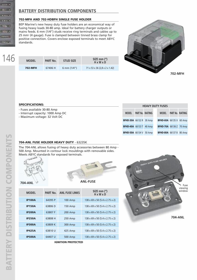
146
BATTERY DISTRIBUTION COMPONENTS 704-ANL FUSE HOLDER HEAVY DUTY - 63235K
The 704-ANL allows fusing of heavy duty accessories between 80 Amp -500 Amp. Mounted in contour lock mouldings with removable sides.Meets ABYC standards for exposed terminals.
704-ANL
ANL-FUSE704-ANLFuse
viewing window
ANL FUSE LINKS MODEL
100 AmpIP100A
150 Amp
SIZE mm (“)H x W x D
IP150A 138 x 69 x 50 (5.4 x 2.75 x 2)
138 x 69 x 50 (5.4 x 2.75 x 2)
200 AmpIP200A
250 AmpIP250A
300 Amp
138 x 69 x 50 (5.4 x 2.75 x 2)
138 x 69 x 50 (5.4 x 2.75 x 2)
138 x 69 x 50 (5.4 x 2.75 x 2)IP300A
425 AmpIP425A
500 Amp
138 x 69 x 50 (5.4 x 2.75 x 2)
138 x 69 x 50 (5.4 x 2.75 x 2)IP500A
PART No.
64395 P
63806 D
63807 F
63808 H
63809 K
63810 U
64407 U
IGNITION PROTECTED
BATTERY DISTRIBUTION COMPONENTS
702-MFH AND 702-HDBFH SINGLE FUSE HOLDER
BEP Marine’s new heavy duty fuse holders are an economical way offusing heavy loads 30-80 amp. Ideal for battery charger outputs ormains feeds. 6 mm (1/4”) studs receive ring terminals and cables up to25 mm2 (4 gauge). Fuse is clamped between tinned brass clamp forpositive connection. Covers enclose exposed terminals to meet ABYCstandards.
702-MFH
STUD SIZE
6 mm (1/4”)
MODEL
702-MFH
SIZE mm (“)H x W x D
71 x 53 x 36 (2,8 x 2 x 1.42)
PART No.
67406 H
RATING
30 Amp
MODEL
BFHD-30A
40 Amp BFHD-40A
50 Amp
PART No.
66132 R
66133 T
66134 VBFHD-50A
RATING
60 Amp
MODEL
BFHD-60A
70 Amp BFHD-70A
80 Amp
PART No.
66135 X
66136 Z
66137 BBFHD-80A
HEAVY DUTY FUSESSPECIFICATIONS:
- Fuses available 30-80 Amp - Interrupt capacity: 1000 Amp DC - Maximum voltage: 32 Volt DC
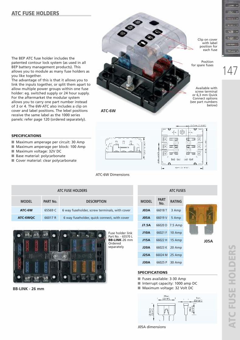
147
ATC FUSE HOLDERS
ATC-6W
BB-LINK - 26 mm
J05A
DESCRIPTION
6 way fuseholder, screw terminals, with cover
MODEL
ATC FUSE HOLDERS
ATC-6W
RATING
3 Amp
MODEL
ATC FUSES
J03A
5 Amp J05A
7.5 Amp J7.5A
10 Amp J10A
15 Amp J15A
20 Amp J20A
25 Amp J25A
30 Amp J30A
PARTNo.
66018 T
66019 V
66020 D
66021 F
66022 H
66023 K
66024 M
66025 P
6 way fuseholder, quick connect, with coverATC-6WQC
PART No.
65569 C
66017 R
The BEP ATC fuse holder includes thepatented contour lock system (as used in allBEP battery management products). Thisallows you to module as many fuse holders asyou like together.The advantage of this is that it allows you tolink the inputs together, or split them apart toallow multiple power groups within one fuseholder: eg. switched supply or 24 hour supply.For the aftermarket the modular systemallows you to carry one part number insteadof 3 or 4. The 6W-ATC also includes a clip oncover and label positions. The lebel positionsreceive the same label as the 1000 seriespanels: refer page 120 (ordered separately).
SPECIFICATIONS
� Maximum amperage per circuit: 30 Amp� Maximum amperage per block: 100 Amp� Maximum voltage: 32V DC� Base material: polycarbonate� Cover material: clear polycarbonate
SPECIFICATIONS
� Fuses available: 3-30 Amp� Interrupt capacity: 1000 amp DC� Maximum voltage: 32 Volt DC
ATC FUSE HOLDERS
Clip on coverwith label
position foreach fuse
Position for spare fuses
Fuse holder linkPart No. - 65570 LBB-LINK-26 mmOrderedseparately
Available with screw terminal
or 6,3 mm QuickConnect options
(see part numbersbelow)
J05A dimensions
ATC-6W Dimensions
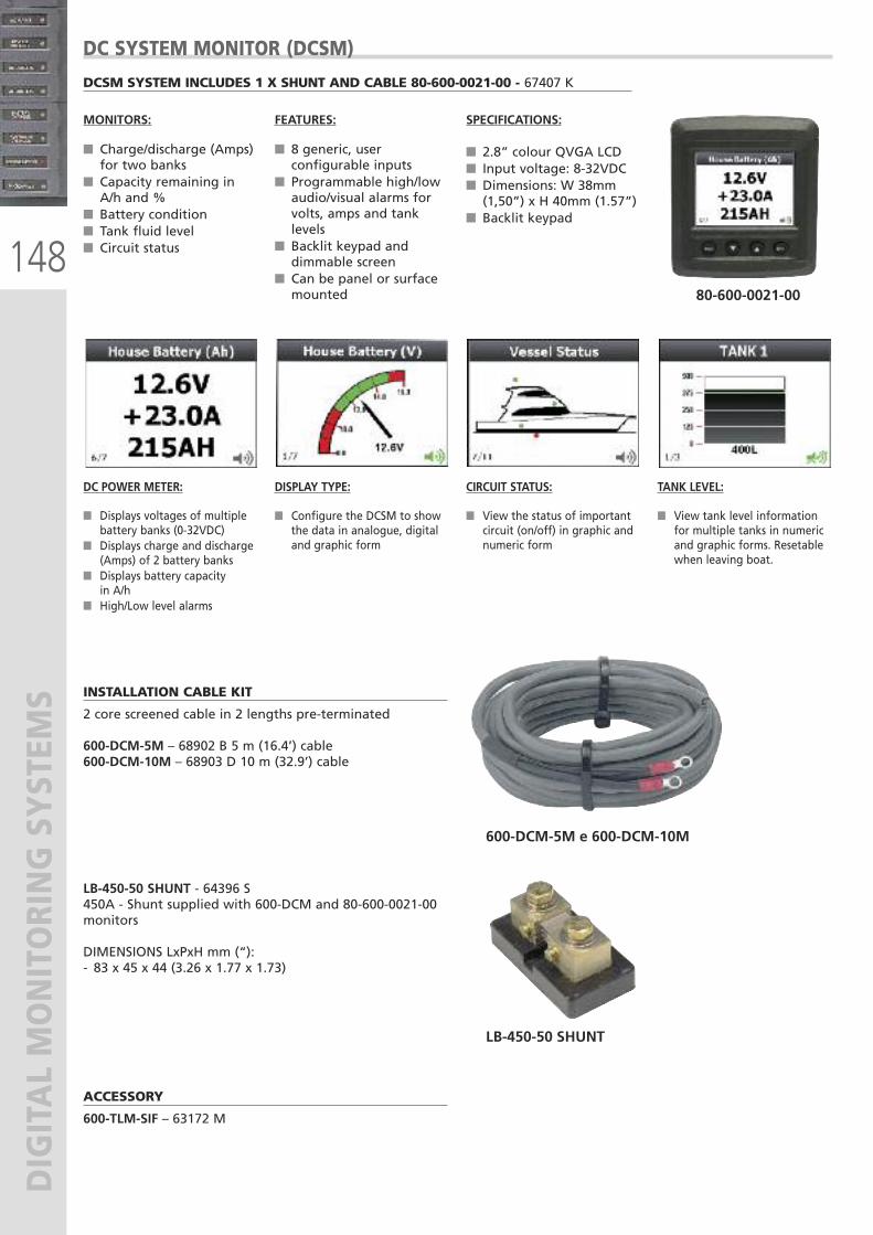
148
DIGITAL MONITORING SYSTEM
S INSTALLATION CABLE KIT
2 core screened cable in 2 lengths pre-terminated
600-DCM-5M – 68902 B 5 m (16.4’) cable600-DCM-10M – 68903 D 10 m (32.9’) cable
LB-450-50 SHUNT - 64396 S450A - Shunt supplied with 600-DCM and 80-600-0021-00monitors
DIMENSIONS LxPxH mm (“):- 83 x 45 x 44 (3.26 x 1.77 x 1.73)
ACCESSORY
600-TLM-SIF – 63172 M
600-DCM-5M e 600-DCM-10M
LB-450-50 SHUNT
80-600-0021-00
DCSM SYSTEM INCLUDES 1 X SHUNT AND CABLE 80-600-0021-00 - 67407 K
DC SYSTEM MONITOR (DCSM)
DC POWER METER:
� Displays voltages of multiplebattery banks (0-32VDC)
� Displays charge and discharge(Amps) of 2 battery banks
� Displays battery capacity in A/h
� High/Low level alarms
DISPLAY TYPE:
� Configure the DCSM to showthe data in analogue, digitaland graphic form
CIRCUIT STATUS:
� View the status of importantcircuit (on/off) in graphic andnumeric form
TANK LEVEL:
� View tank level informationfor multiple tanks in numericand graphic forms. Resetablewhen leaving boat.
MONITORS:
� Charge/discharge (Amps)for two banks
� Capacity remaining inA/h and %
� Battery condition� Tank fluid level� Circuit status
FEATURES:
� 8 generic, userconfigurable inputs
� Programmable high/lowaudio/visual alarms forvolts, amps and tanklevels
� Backlit keypad anddimmable screen
� Can be panel or surfacemounted
SPECIFICATIONS:
� 2.8” colour QVGA LCD� Input voltage: 8-32VDC� Dimensions: W 38mm(1,50”) x H 40mm (1.57”)
� Backlit keypad
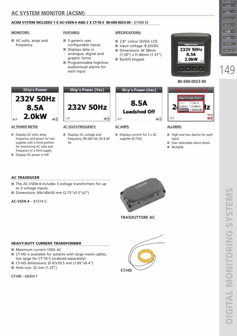
149
DIGITAL MONITORING SYSTEM
S
AC TRASDUCER
� The AC-VSEN-4 includes 3 voltage transformers for upto 3 voltage inputs.
� Dimensions: 69x140x50 mm (2.75”x5.5”x2”)
AC-VSEN-4 – 67314 C
HEAVY-DUTY CURRENT TRANSFORMER
� Maximum current 150A AC � CT-HD is available for systems with large mains cables,too large for CT-10-3 (ordered separately)
� CT-HD dimensions: Ø 47x10.5 mm (1.85”x0.4”)� Hole size: 32 mm (1.25”)
CT-HD - 68904 F
TRASDUTTORE AC
CT-HD
80-600-0023-00
ACSM SYSTEM INCLUDES 1 X AC-VSEN-4 AND 2 X CT-10-3 80-600-0023-00 - 67408 M
AC SYSTEM MONITOR (ACSM)
AC POWER METER:
� Displays AC volts, ampsfrequency and power for twosupplies with a third positionfor monitoring AC volts andfrequency of a third supply
� Displays AC power in kW
AC VOLTS/FREQUENCY:
� Displays AC voltage andfrequency, 80-264 Vac 50 & 60Hz
AC AMPS:
� Displays current for 2 x ACsupplies (0-75A)
ALLARMS:
� High and low alarms for eachinput
� User selectable alarm levels� Mutable
MONITORS:
� AC volts, amps andfrequency
FEATURES:
� 3 generic userconfigurable inputs
� Displays data inanalogue, digital andgraphic forms
� Programmable high/lowaudio/visual alarms foreach input
SPECIFICATIONS:
� 2.8” colour QVGA LCD� Input voltage: 8-32VDC� Dimensions: W 38mm(1,50”) x H 40mm (1.57”)
� Backlit keypad
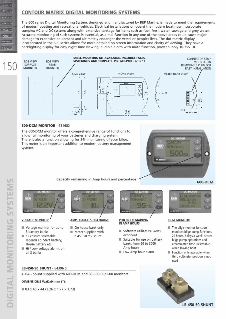
150
DIGITAL MONITORING SYSTEM
SThe 600 series Digital Monitoring System, designed and manufactured by BEP Marine, is made to meet the requirementsof modern boating and recreational vehicles. Electrical installations on-board the modern boat now incorporatecomplex AC and DC systems along with extensive tankage for items such as fuel, fresh water, sewage and grey water.Accurate monitoring of such systems is essential, as a mal-function in any one of the above areas could cause majordamage to expensive equipment and ultimately endanger the vessel or peoples lives. The dot matrix displayincorporated in the 600 series allows for more detailed on-screen information and clarity of viewing. They have abacklighting display for easy night time viewing, audible alarm with mute function, power supply 10-35V DC.
600-DCM MONITOR - 63168X
The 600-DCM monitor offers a comprehensive range of functions toallow full monitoring of your batteries and charging system.There is also a function allowing for 24h monitoring of your bilge. This meter is an important addition to modern battery managementsystems.
Capacity remaining in Amp hours and percentage
LB-450-50 SHUNT - 64396 S
450A - Shunt supplied with 600-DCM and 80-600-0021-00 monitors
DIMENSIONS WxDxH mm (“):
� 83 x 45 x 44 (3.26 x 1.77 x 1.73)
VOLTAGE MONITOR:
� Voltage monitor for up to3 battery banks
� 12 costum selectablelegends eg: Start battery,House battery etc.
� Hi / Low voltage alarms onall 3 banks
AMP CHARGE & DISCHARGE:
� On house bank only� Meter supplied witha 450-50 mV shunt
PERCENT REMAININGIN AMP HOURS:
� Software utilizes Peukertsexponent
� Suitable for use on batterybanks from 60 to 3000Amp hours
� Low Amp hour alarm
BILGE MONITOR
� The bilge monitor functionmonitors bilge pump functions24 hours, 7 days a week. Storesbilge pump operations andaccumulated time. Resettablewhen leaving boat.
� Function only available whenthird voltmeter position is notused
600-DCM
LB-450-50-SHUNT
CONTOUR MATRIX DIGITAL MONITORING SYSTEMS
SIDE VIEWSURFACEMOUNTED
SIDE VIEWREAR
MOUNTED
SIDE VIEW FRONT VIEW METER REAR VIEW
CONNECTOR STRIPMOUNTED IN
REMOVABLE PLUG FOREASY INSTALLATION
PANEL MOUNTING KIT AVAILABLE. INCLUDES FACIA, FASTENINGS AND TEMPLATE. P.N. 600-PMK - 65177 J
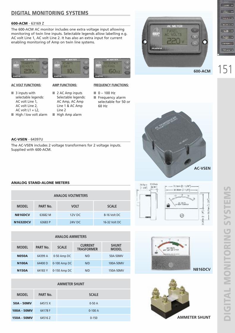
151
DIGITAL MONITORING SYSTEM
S
600-ACM - 63169 Z
The 600-ACM AC monitor includes one extra voltage input allowingmonitoring of twin line inputs. Selectable legends allow labelling e.g.AC volt Line 1, AC volt Line 2. It has also an extra input for currentenabling monitoring of Amp on twin line systems.
AC VOLT FUNCTIONS:
� 3 inputs withselectable legends:AC volt Line 1,AC volt Line 2,AC volt L1 + L2,
� High / low volt alarm
AMP FUNCTIONS:
� 2 AC Amp inputsSelectable legends:AC Amp, AC AmpLine 1 & AC AmpLine 2
� High Amp alarm
FREQUENCY FUNCTIONS:
� 0 – 100 Hz� Frequency alarmselectable for 50 or60 Hz
600-ACM
AC-VSEN - 64397U
The AC-VSEN includes 2 voltage transformers for 2 voltage inputs.Supplied with 600-ACM.
ANALOG STAND-ALONE METERS
AC-VSEN
DIGITAL MONITORING SYSTEMS
AMMETER SHUNT
N816DCV
VOLT
12V DC
MODEL
ANALOG VOLTMETERS
N816DCV
SCALE
8-16 Volt DC
24V DCN1632DCV
PART No.
63682 M
63683 P 16-32 Volt DC
SCALE
0-50 Amp DC
MODEL
ANALOG AMMETERS
N050A
CURRENTTRASFORMER
N/D
0-100 Amp DCN100A N/D
SHUNTMODEL
50A-50MV
100A-50MV
0-150 Amp DCN150A
PART No.
64399 A
64400 D
64183 Y N/D 150A-50MV
SCALE
0-50 A
MODEL
AMMETER SHUNT
50A - 50MV
0-100 A100A - 50MV
0-150 150A - 50MV
PART No.
64515 X
64178 F
64516 Z
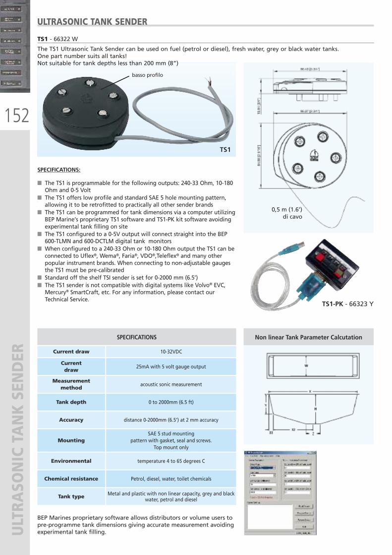
152
ULTRA
SONIC TANK SENDER
TS1 - 66322 W
The TS1 Ultrasonic Tank Sender can be used on fuel (petrol or diesel), fresh water, grey or black water tanks.One part number suits all tanks!Not suitable for tank depths less than 200 mm (8”)
SPECIFICATIONS:
� The TS1 is programmable for the following outputs: 240-33 Ohm, 10-180Ohm and 0-5 Volt
� The TS1 offers low profile and standard SAE 5 hole mounting pattern,allowing it to be retrofitted to practically all other sender brands
� The TS1 can be programmed for tank dimensions via a computer utilizingBEP Marine’s proprietary TS1 software and TS1-PK kit software avoidingexperimental tank filling on site
� The TS1 configured to a 0-5V output will connect straight into the BEP600-TLMN and 600-DCTLM digital tank monitors
� When configured to a 240-33 Ohm or 10-180 Ohm output the TS1 can beconnected to Uflex®, Wema®, Faria®, VDO®,Teleflex® and many otherpopular instrument brands. When connecting to non-adjustable gaugesthe TS1 must be pre-calibrated
� Standard off the shelf TSI sender is set for 0-2000 mm (6.5’)� The TS1 sender is not compatible with digital systems like Volvo® EVC,Mercury® SmartCraft, etc. For any information, please contact ourTechnical Service.
ULTRASONIC TANK SENDER
TS1
0,5 m (1.6’)di cavo
basso profilo
TS1-PK - 66323 Y
Non linear Tank Parameter Calcutation
BEP Marines proprietary software allows distributors or volume users topre-programme tank dimensions giving accurate measurement avoidingexperimental tank filling.
SPECIFICATIONS
Current draw 10-32VDC
Currentdraw
25mA with 5 volt gauge output
Measurementmethod
acoustic sonic measurement
Tank depth 0 to 2000mm (6.5 ft)
Accuracy distance 0-2000mm (6.5’) at 2 mm accuracy
Mounting SAE 5 stud mounting
pattern with gasket, seal and screws. Top mount only
Environmental temperature 4 to 65 degrees C
Chemical resistance Petrol, diesel, water, toilet chemicals
Tank type Metal and plastic with non linear capacity, grey and blackwater, petrol and diesel
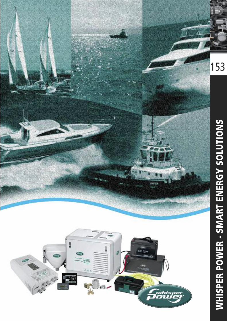
153
WHISPER POWER - SM
ART ENERGY SOLUTIONS
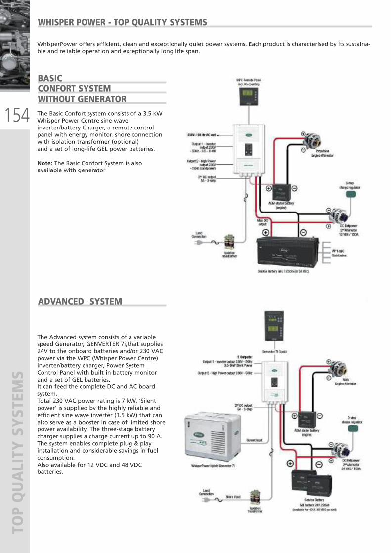
154
TOP QUALITY SYSTEM
S
BASIC CONFORT SYSTEMWITHOUT GENERATOR The Basic Confort system consists of a 3.5 kW Whisper Power Centre sine waveinverter/battery Charger, a remote controlpanel with energy monitor, shore connectionwith isolation transformer (optional)and a set of long-life GEL power batteries.
Note: The Basic Confort System is alsoavailable with generator
WhisperPower offers efficient, clean and exceptionally quiet power systems. Each product is characterised by its sustaina-ble and reliable operation and exceptionally long life span.
ADVANCED SYSTEM
The Advanced system consists of a variablespeed Generator, GENVERTER 7i,that supplies24V to the onboard batteries and/or 230 VACpower via the WPC (Whisper Power Centre)inverter/battery charger, Power SystemControl Panel with built-in battery monitorand a set of GEL batteries.It can feed the complete DC and AC boardsystem. Total 230 VAC power rating is 7 kW. ‘Silentpower’ is supplied by the highly reliable andefficient sine wave inverter (3.5 kW) that canalso serve as a booster in case of limited shorepower availability, The three-stage batterycharger supplies a charge current up to 90 A.The system enables complete plug & playinstallation and considerable savings in fuelconsumption.Also available for 12 VDC and 48 VDCbatteries.
WHISPER POWER - TOP QUALITY SYSTEMS
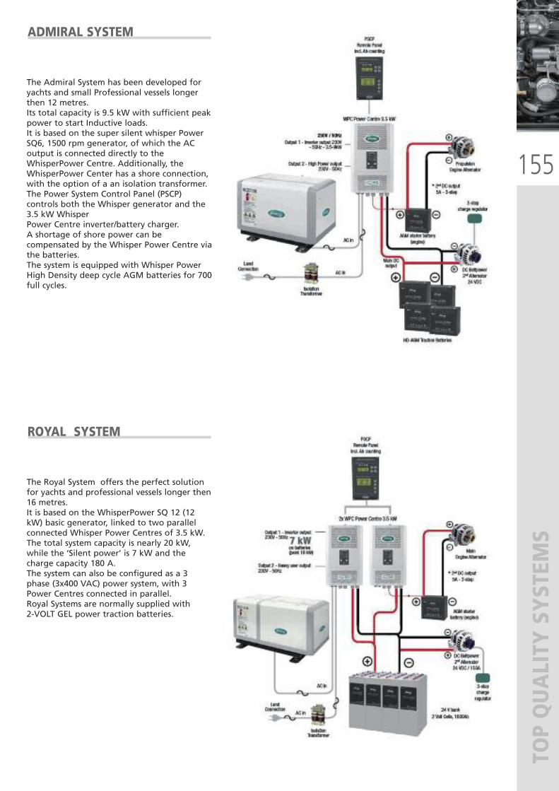
155
TOP QUALITY SYSTEM
S
ADMIRAL SYSTEM
The Admiral System has been developed foryachts and small Professional vessels longerthen 12 metres.Its total capacity is 9.5 kW with sufficient peakpower to start Inductive loads.It is based on the super silent whisper PowerSQ6, 1500 rpm generator, of which the ACoutput is connected directly to theWhisperPower Centre. Additionally, theWhisperPower Center has a shore connection,with the option of a an isolation transformer.The Power System Control Panel (PSCP)controls both the Whisper generator and the3.5 kW WhisperPower Centre inverter/battery charger. A shortage of shore power can becompensated by the Whisper Power Centre viathe batteries. The system is equipped with Whisper PowerHigh Density deep cycle AGM batteries for 700full cycles.
ROYAL SYSTEM
The Royal System offers the perfect solutionfor yachts and professional vessels longer then16 metres.It is based on the WhisperPower SQ 12 (12kW) basic generator, linked to two parallelconnected Whisper Power Centres of 3.5 kW.The total system capacity is nearly 20 kW,while the ‘Silent power’ is 7 kW and thecharge capacity 180 A.The system can also be configured as a 3phase (3x400 VAC) power system, with 3Power Centres connected in parallel.Royal Systems are normally supplied with 2-VOLT GEL power traction batteries.
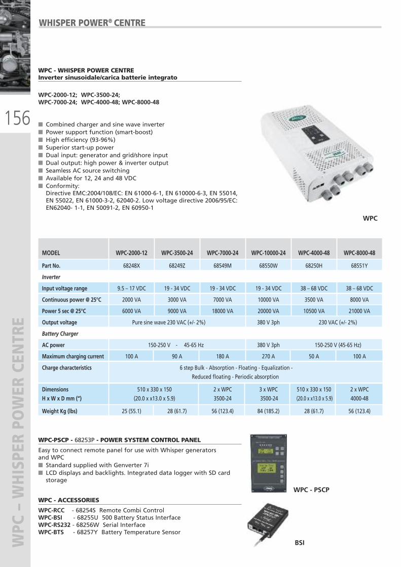
156
WPC – WHISPER POWER CENTRE
WPC - WHISPER POWER CENTREInverter sinusoidale/carica batterie integrato
WPC-2000-12; WPC-3500-24;WPC-7000-24; WPC-4000-48; WPC-8000-48
� Combined charger and sine wave inverter� Power support function (smart-boost)� High efficiency (93-96%)� Superior start-up power� Dual input: generator and grid/shore input� Dual output: high power & inverter output� Seamless AC source switching� Available for 12, 24 and 48 VDC� Conformity:Directive EMC:2004/108/EC: EN 61000-6-1, EN 610000-6-3, EN 55014,EN 55022, EN 61000-3-2, 62040-2. Low voltage directive 2006/95/EC:EN62040- 1-1, EN 50091-2, EN 60950-1
WPC-PSCP - 68253P - POWER SYSTEM CONTROL PANEL
Easy to connect remote panel for use with Whisper generators and WPC � Standard supplied with Genverter 7i � LCD displays and backlights. Integrated data logger with SD cardstorage
WPC - ACCESSORIES
WPC-RCC - 68254S Remote Combi ControlWPC-BSI - 68255U 500 Battery Status InterfaceWPC-RS232 - 68256W Serial InterfaceWPC-BTS - 68257Y Battery Temperature Sensor
WPC - PSCP
BSI
WPC
MODEL WPC-2000-12 WPC-3500-24 WPC-7000-24 WPC-10000-24 WPC-4000-48 WPC-8000-48
Part No. 68248X 68249Z 68549M 68550W 68250H 68551Y
Inverter
Input voltage range 9.5 – 17 VDC 19 - 34 VDC 19 - 34 VDC 19 - 34 VDC 38 – 68 VDC 38 – 68 VDC
Continuous power @ 25°C 2000 VA 3000 VA 7000 VA 10000 VA 3500 VA 8000 VA
Power 5 sec @ 25°C 6000 VA 9000 VA 18000 VA 20000 VA 10500 VA 21000 VA
Output voltage Pure sine wave 230 VAC (+/- 2%) 380 V 3ph 230 VAC (+/- 2%)
Battery Charger
AC power 150-250 V - 45-65 Hz 380 V 3ph 150-250 V (45-65 Hz)
Maximum charging current 100 A 90 A 180 A 270 A 50 A 100 A
Charge characteristics 6 step Bulk - Absorption - Floating - Equalization -
Reduced floating - Periodic absorption
Dimensions 510 x 330 x 150 2 x WPC 3 x WPC 510 x 330 x 150 2 x WPC
H x W x D mm (“) (20.0 x x13.0 x 5.9) 3500-24 3500-24 (20.0 x x13.0 x 5.9) 4000-48
Weight Kg (lbs) 25 (55.1) 28 (61.7) 56 (123.4) 84 (185.2) 28 (61.7) 56 (123.4)
WHISPER POWER® CENTRE
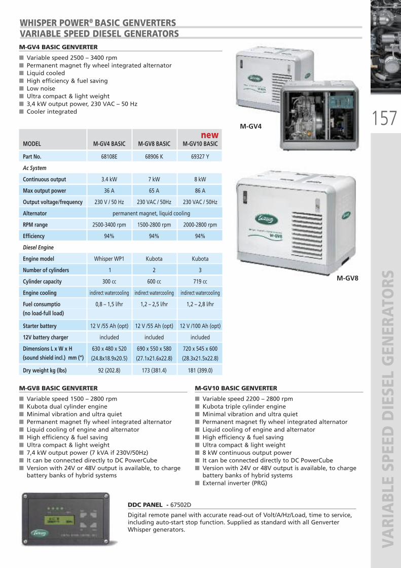
157
VARIABLE SPEED DIESEL GENERATORS
M-GV4 BASIC GENVERTER
� Variable speed 2500 – 3400 rpm� Permanent magnet fly wheel integrated alternator� Liquid cooled� High efficiency & fuel saving� Low noise� Ultra compact & light weight� 3,4 kW output power, 230 VAC – 50 Hz� Cooler integrated
M-GV8 BASIC GENVERTER
� Variable speed 1500 – 2800 rpm� Kubota dual cylinder engine� Minimal vibration and ultra quiet� Permanent magnet fly wheel integrated alternator� Liquid cooling of engine and alternator� High efficiency & fuel saving� Ultra compact & light weight � 7,4 kW output power (7 kVA if 230V/50Hz)� It can be connected directly to DC PowerCube� Version with 24V or 48V output is available, to chargebattery banks of hybrid systems
M-GV10 BASIC GENVERTER
� Variable speed 2200 – 2800 rpm� Kubota triple cylinder engine� Minimal vibration and ultra quiet� Permanent magnet fly wheel integrated alternator� Liquid cooling of engine and alternator� High efficiency & fuel saving� Ultra compact & light weight� 8 kW continuous output power � It can be connected directly to DC PowerCube� Version with 24V or 48V output is available, to chargebattery banks of hybrid systems
� External inverter (PRG)
M-GV4
M-GV8
MODEL M-GV4 BASIC M-GV8 BASIC M-GV10 BASIC
Part No. 68108E 68906 K 69327 Y
Ac System
Continuous output 3.4 kW 7 kW 8 kW
Max output power 36 A 65 A 86 A
Output voltage/frequency 230 V / 50 Hz 230 VAC / 50Hz 230 VAC / 50Hz
Alternator permanent magnet, liquid cooling
RPM range 2500-3400 rpm 1500-2800 rpm 2000-2800 rpm
Efficiency 94% 94% 94%
Diesel Engine
Engine model Whisper WP1 Kubota Kubota
Number of cylinders 1 2 3
Cylinder capacity 300 cc 600 cc 719 cc
Engine cooling indirect watercooling indirect watercooling indirect watercooling
Fuel consumptio 0,8 – 1,5 l/hr 1,2 – 2,5 l/hr 1,2 – 2,8 l/hr
(no load-full load)
Starter battery 12 V /55 Ah (opt) 12 V /55 Ah (opt) 12 V /100 Ah (opt)
12V battery charger included included included
Dimensions L x W x H 630 x 480 x 520 690 x 550 x 580 720 x 545 x 600
(sound shield incl.) mm (“) (24.8x18.9x20.5) (27.1x21.6x22.8) (28.3x21.5x22.8)
Dry weight kg (lbs) 92 (202.8) 173 (381.4) 181 (399.0)
WHISPER POWER® BASIC GENVERTERSVARIABLE SPEED DIESEL GENERATORS
DDC PANEL - 67502D
Digital remote panel with accurate read-out of Volt/A/Hz/Load, time to service,including auto-start stop function. Supplied as standard with all GenverterWhisper generators.
new new

158
VARIABLE SPEED DIESEL GENERATORS
MODEL M-GV 7i
PART No. 67708 A (12 VDC) 67709 C (24 VDC)
SPECIFICATIONS
Variable speed 2400–3400 gpm
Combined system output 5.8 kW / 12 V, 7 kW / 24 VDC
Generator power (running engine) 3.8 kW
Silent power (inverter mode) 2.0 kW / 12V, 3.5 kW 24 VDC
INVERTER / GENERATOR
Peak output AC 60.0 A
Nominal voltage 230 Vac
Nominal current AC (combined) 30.0 A
Nominal frequency AC 50.0 Hz
Leading or lagging power factor 0,1 - 1
Parallel use (multiple systems) not possible
Capacity (starter) battery (AGM) 12 V 55 Ah
Starter battery charge current 10 A maintenance charger
BATTERY CHARGER
Charge current 12 V model 100 A,
24 V model 90 A,
Charge characteristic 3-step, IUoUo
AC Shorepower 190 – 260 Vac
Temperature sensor Yes
MECHANICAL SPECIFICATIONS
Cooling indirect watercooling
Max operation angle (in all directions)
25°
Temperature range operational -20° to 60 °C
Relative umidity max 95% rel. umidity, none condensing
Remote control WPC-PSCP panel
DIESEL ENGINE
Engine model Whisper WP1
Number of cylinders 1
Cylinder capacity 300 cc
Air conumption 0.42 m3/min @ 3000 gpm
Engine cooling indirect watercooling
Fuel consumption(no load-full load)
0.8- 1.5 liters/hour
DIMENSIONS & WEIGHT
Generator Combi - enclosure
D x W x H mm (“) 630 x 480 x 520 500 x 360 x 300
(24.8x18.9x20.5) (19.6x14.2x11.8)
Dry weight kg (lbs) 92 (202.8) 25 (55.1)
Dry exhaust pipe Ø 1⅝ inch BSP inner thread
WPC-PSCP 68253 P
Power System control panelCombined remote control and monitoringpanel for Whisper Power generators andGenverter Series
M –GV 7I GENVERTERHybrid generator variable speed
M-GV 7i
WPC-PSCP
M-GV 7I DIESEL GENERATOR + INVERTER +BATTERY CHARGER
� 3.4 kW/230VAC diesel generator� 3.5 kW/230VAC sine wave inverter� Built-in charger for 12 or 24V DC batteries
� Land power connection� Variable speed 2500-3400 rpm� Fully automatic operation� Silent, liquid cooled diesel engine� Plug & Play installation� Combined output 6 kVA cont./7 kVA max (24V models)
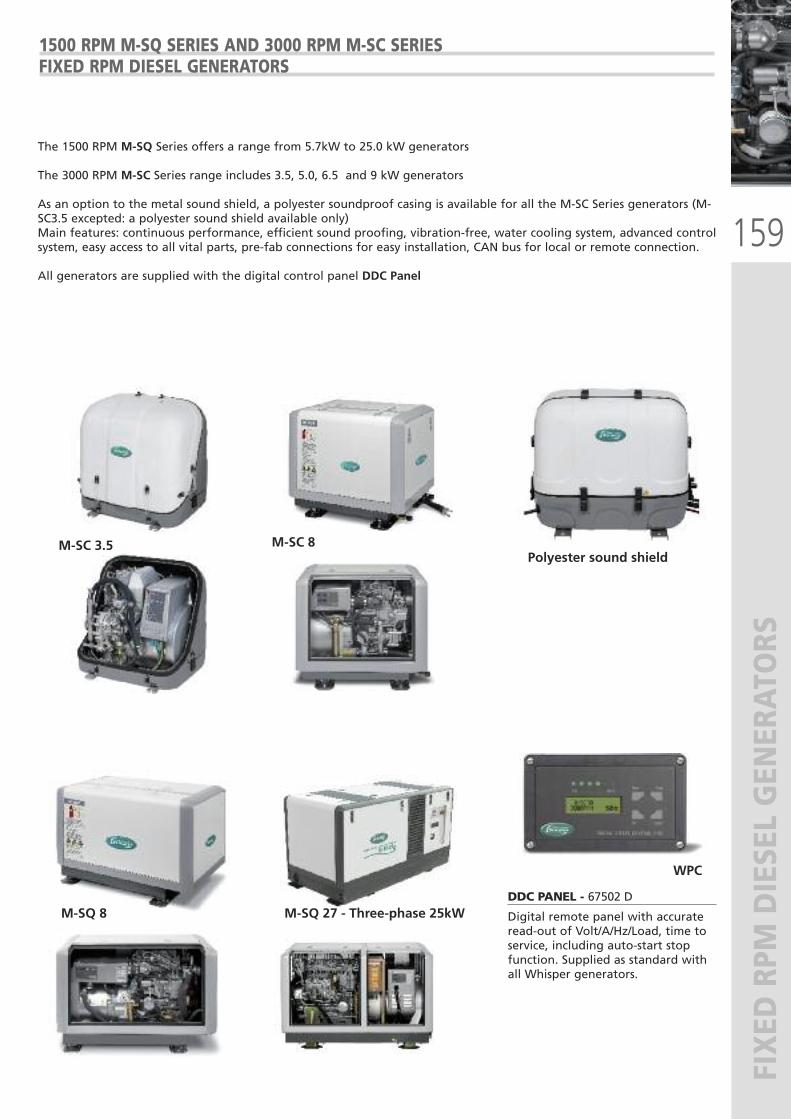
159
FIXED RPM
DIESEL GENERATORS
DDC PANEL - 67502 D
Digital remote panel with accurateread-out of Volt/A/Hz/Load, time toservice, including auto-start stopfunction. Supplied as standard withall Whisper generators.
1500 RPM M-SQ SERIES AND 3000 RPM M-SC SERIES FIXED RPM DIESEL GENERATORS
M-SC 3.5 M-SC 8
M-SQ 8 M-SQ 27 - Three-phase 25kW
Polyester sound shield
WPC
The 1500 RPM M-SQ Series offers a range from 5.7kW to 25.0 kW generators
The 3000 RPM M-SC Series range includes 3.5, 5.0, 6.5 and 9 kW generators
As an option to the metal sound shield, a polyester soundproof casing is available for all the M-SC Series generators (M-SC3.5 excepted: a polyester sound shield available only)Main features: continuous performance, efficient sound proofing, vibration-free, water cooling system, advanced controlsystem, easy access to all vital parts, pre-fab connections for easy installation, CAN bus for local or remote connection.
All generators are supplied with the digital control panel DDC Panel
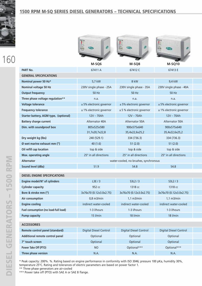
160
DIESEL GENERATORS – 1500 RPM
1500 RPM M-SQ SERIES DIESEL GENERATORS – TECHNICAL SPECIFICATIONS
* Peak capacity: 200%. %. Rating based on engine performance in conformity with ISO 3046; pressure 100 pKa, humidity 30%,temperature 25°C. Rating and tolerances of electric parameters are based on power factor 1.** Three phase generators are air-cooled*** Power take off (PTO) with SAE A or SAE B flange.
PART No. 67411 A 67412 C 67413 E 67342 H 67414 G 67415 J 67416 L
GENERAL SPECIFICATIONS
Nominal power 50 Hz* 5,7 kW 8 kW 9,4 kW 12 kW 16 kW 20 kW 25 kW
Nominal voltage 50 Hz 230V single phase - 25A 230V single phase - 35A 230V single phase - 40A 230V single phase - 52A 230V single phase - 70A 230V single phase - 86A 230V-400V Three-phase - 3x39A
Output frequency 50 Hz 50 Hz 50 Hz 50 Hz 50 Hz 50 Hz 50 Hz
Three phase voltage regulation** n.a. n.a. n.a. AVR, ± 2% tolerance AVR, ± 2% tolerance AVR, ± 2% tolerance AVR, ± 2% tolerance
Voltage tolerance ± 5% electronic governor ± 5% electronic governor ± 5% electronic governor ± 5% electronic governor ± 5% electronic governor ± 2% electronic governor ± 2% electronic governor
Frequency tolerance ± 1% electronic governor ± 5 % electronic governor ± 1% electronic governor ± 1% electronic governor ± 3% electronic governor ± 3% electronic governor ± 3% electronic governor
Starter battery, AGM type, (optional) 12V – 70Ah 12V – 70Ah 12V – 70Ah 12V – 70Ah 12V – 120Ah 12V – 160Ah 12V – 145Ah
Battery charge current Alternator 40A Alternator 50A Alternator 50A Alternator 50A Alternator 50A Alternator 50A Alternator 50A
Dim. with soundproof box 805x525x580 900x575x640 900x575x640 1060x575x640 1060x575x640 1260x680x800 1550x749x805
31,7x20,7x22,8 35,4x22,6x25,2 35,4x22,6x25,2 41,7x22,6x25,2 41,7x22,6x25,2 49,6x26,8x31,5 61x29.5x31.7
Dry weight kg (lbs) 240 (529.1) 334 (736.3) 334 (736.3) 380 (837.7) 454 (1000.9) 580 (1278.7) 640 (11411)
Ø wet marine exhaust mm (“) 40 (1.6) 51 (2.0) 51 (2.0) 51 (2.0) 51 (2.0) 63 (2.5) 63 (2.5)
Oil refill cap location top & side top & side top & side top & side top & side top & side top & side
Max. operating angle 25° in all directions 25° in all directions 25° in all directions 25° in all directions 25° in all directions 25° in all directions 25° in all directions
Alternator water-cooled, no brushes, synchronous water-cooled, no brushes, synchronous
Sound level (dBa) 51.9 54.8 54.8 55.7 56.1 58.3 58.0
DIESEL ENGINE SPECIFICATIONS
Engine model/N° of cylinders L3E / 3 S3L2 / 3 S3L2 / 3 S4L2 / 4 S4Q2 / 4 S4S / 4 S4S / 4
Cylinder capacity 952 cc 1318 cc 1318 cc 1758 cc 2505 cc 3331 cc 3331 cc
Bore & stroke mm (“) 3x76x70 (0.12x3.0x2.75) 3x76x70 (0.12x3.0x2.75) 3x76x70 (0.12x3.0x2.75) 4x78x92 (0.15x3.0x2.75) 4x88x103 (0.15x3.5x4.0) 4x94x120 (0.15x3.7x4.7) 4x94x120 (0.15x3.7x4.7)
Air consumption 0,8 m3/min 1,1 m3/min 1,1 m3/min 1,5 m3/min 2,1 m3/min 2,8 m3/min 2,8 m3/min
Engine cooling indirect water-cooled indirect water-cooled indirect water-cooled indirect water-cooled indirect water-cooled indirect water-cooled indirect water-cooled
Fuel consumption (no load-full load) 1-3 l/hours 1-3 l/hours 1-3 l/hours 1-4 l/hours 1-5 l/hours 1-6 l/hours 1-8 l/hours
Pump capacity 15 l/min 18 l/min 18 l/min 18 l/min 22 l/min 22 l/min 22 l/min
ACCESSORIES
Remote control panel (standard) Digital Diesel Control Digital Diesel Control Digital Diesel Control Digital Diesel Control Digital Diesel Control Digital Diesel Control Digital Diesel Control
Additional remote control panel Optional Optional Optional Optional Optional Optional Optional
7” touch screen Optional Optional Optional Optional Optional Optional Optional
Power Take Off (PTO) NO Optional*** Optional*** Optional*** Optional*** Optional*** Optional***
Three phase version N.A. N.A. N.A. Yes Yes Yes Std
M-SQ6 M-SQ8 M-SQ10
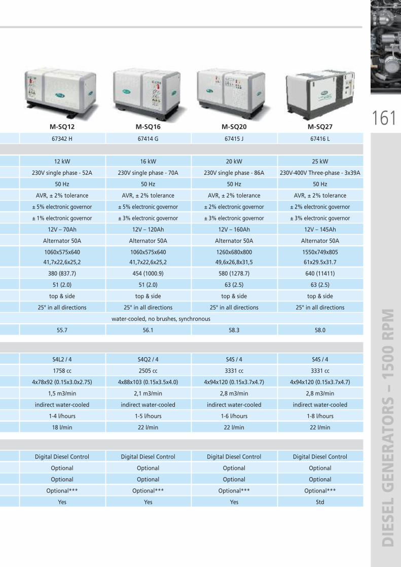
161
DIESEL GENERATORS – 1500 RPM
1500 RPM M-SQ SERIES DIESEL GENERATORS – TECHNICAL SPECIFICATIONS
PART No. 67411 A 67412 C 67413 E 67342 H 67414 G 67415 J 67416 L
GENERAL SPECIFICATIONS
Nominal power 50 Hz* 5,7 kW 8 kW 9,4 kW 12 kW 16 kW 20 kW 25 kW
Nominal voltage 50 Hz 230V single phase - 25A 230V single phase - 35A 230V single phase - 40A 230V single phase - 52A 230V single phase - 70A 230V single phase - 86A 230V-400V Three-phase - 3x39A
Output frequency 50 Hz 50 Hz 50 Hz 50 Hz 50 Hz 50 Hz 50 Hz
Three phase voltage regulation** n.a. n.a. n.a. AVR, ± 2% tolerance AVR, ± 2% tolerance AVR, ± 2% tolerance AVR, ± 2% tolerance
Voltage tolerance ± 5% electronic governor ± 5% electronic governor ± 5% electronic governor ± 5% electronic governor ± 5% electronic governor ± 2% electronic governor ± 2% electronic governor
Frequency tolerance ± 1% electronic governor ± 5 % electronic governor ± 1% electronic governor ± 1% electronic governor ± 3% electronic governor ± 3% electronic governor ± 3% electronic governor
Starter battery, AGM type, (optional) 12V – 70Ah 12V – 70Ah 12V – 70Ah 12V – 70Ah 12V – 120Ah 12V – 160Ah 12V – 145Ah
Battery charge current Alternator 40A Alternator 50A Alternator 50A Alternator 50A Alternator 50A Alternator 50A Alternator 50A
Dim. with soundproof box 805x525x580 900x575x640 900x575x640 1060x575x640 1060x575x640 1260x680x800 1550x749x805
31,7x20,7x22,8 35,4x22,6x25,2 35,4x22,6x25,2 41,7x22,6x25,2 41,7x22,6x25,2 49,6x26,8x31,5 61x29.5x31.7
Dry weight kg (lbs) 240 (529.1) 334 (736.3) 334 (736.3) 380 (837.7) 454 (1000.9) 580 (1278.7) 640 (11411)
Ø wet marine exhaust mm (“) 40 (1.6) 51 (2.0) 51 (2.0) 51 (2.0) 51 (2.0) 63 (2.5) 63 (2.5)
Oil refill cap location top & side top & side top & side top & side top & side top & side top & side
Max. operating angle 25° in all directions 25° in all directions 25° in all directions 25° in all directions 25° in all directions 25° in all directions 25° in all directions
Alternator water-cooled, no brushes, synchronous water-cooled, no brushes, synchronous
Sound level (dBa) 51.9 54.8 54.8 55.7 56.1 58.3 58.0
DIESEL ENGINE SPECIFICATIONS
Engine model/N° of cylinders L3E / 3 S3L2 / 3 S3L2 / 3 S4L2 / 4 S4Q2 / 4 S4S / 4 S4S / 4
Cylinder capacity 952 cc 1318 cc 1318 cc 1758 cc 2505 cc 3331 cc 3331 cc
Bore & stroke mm (“) 3x76x70 (0.12x3.0x2.75) 3x76x70 (0.12x3.0x2.75) 3x76x70 (0.12x3.0x2.75) 4x78x92 (0.15x3.0x2.75) 4x88x103 (0.15x3.5x4.0) 4x94x120 (0.15x3.7x4.7) 4x94x120 (0.15x3.7x4.7)
Air consumption 0,8 m3/min 1,1 m3/min 1,1 m3/min 1,5 m3/min 2,1 m3/min 2,8 m3/min 2,8 m3/min
Engine cooling indirect water-cooled indirect water-cooled indirect water-cooled indirect water-cooled indirect water-cooled indirect water-cooled indirect water-cooled
Fuel consumption (no load-full load) 1-3 l/hours 1-3 l/hours 1-3 l/hours 1-4 l/hours 1-5 l/hours 1-6 l/hours 1-8 l/hours
Pump capacity 15 l/min 18 l/min 18 l/min 18 l/min 22 l/min 22 l/min 22 l/min
ACCESSORIES
Remote control panel (standard) Digital Diesel Control Digital Diesel Control Digital Diesel Control Digital Diesel Control Digital Diesel Control Digital Diesel Control Digital Diesel Control
Additional remote control panel Optional Optional Optional Optional Optional Optional Optional
7” touch screen Optional Optional Optional Optional Optional Optional Optional
Power Take Off (PTO) NO Optional*** Optional*** Optional*** Optional*** Optional*** Optional***
Three phase version N.A. N.A. N.A. Yes Yes Yes Std
M-SQ12 M-SQ16 M-SQ20 M-SQ27
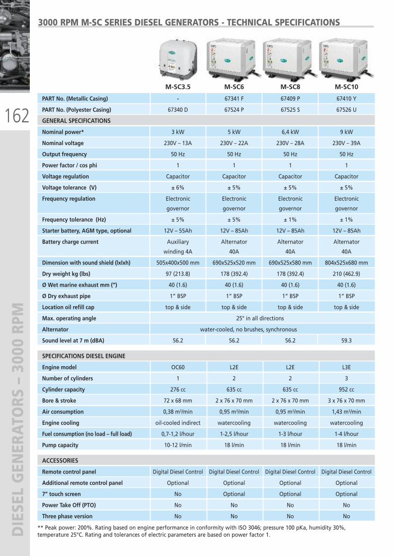
162
DIESEL GENERATORS – 3000 RPM
3000 RPM M-SC SERIES DIESEL GENERATORS - TECHNICAL SPECIFICATIONS
** Peak power: 200%. Rating based on engine performance in conformity with ISO 3046; pressure 100 pKa, humidity 30%,temperature 25°C. Rating and tolerances of electric parameters are based on power factor 1.
PART No. (Metallic Casing) - 67341 F 67409 P 67410 Y
PART No. (Polyester Casing) 67340 D 67524 P 67525 S 67526 U
GENERAL SPECIFICATIONS
Nominal power* 3 kW 5 kW 6,4 kW 9 kW
Nominal voltage 230V – 13A 230V – 22A 230V – 28A 230V – 39A
Output frequency 50 Hz 50 Hz 50 Hz 50 Hz
Power factor / cos phi 1 1 1 1
Voltage regulation Capacitor Capacitor Capacitor Capacitor
Voltage tolerance (V) ± 6% ± 5% ± 5% ± 5%
Frequency regulation Electronic Electronic Electronic Electronic
governor governor governor governor
Frequency tolerance (Hz) ± 5% ± 5% ± 1% ± 1%
Starter battery, AGM type, optional 12V – 55Ah 12V – 85Ah 12V – 85Ah 12V – 85Ah
Battery charge current Auxiliary Alternator Alternator Alternator
winding 4A 40A 40A 40A
Dimension with sound shield (lxlxh) 505x400x500 mm 690x525x520 mm 690x525x580 mm 804x525x680 mm
Dry weight kg (lbs) 97 (213.8) 178 (392.4) 178 (392.4) 210 (462.9)
Ø Wet marine exhaust mm (“) 40 (1.6) 40 (1.6) 40 (1.6) 40 (1.6)
Ø Dry exhaust pipe 1” BSP 1” BSP 1” BSP 1” BSP
Location oil refill cap top & side top & side top & side top & side
Max. operating angle 25° in all directions
Alternator water-cooled, no brushes, synchronous
Sound level at 7 m (dBA) 56.2 56.2 56.2 59.3
SPECIFICATIONS DIESEL ENGINE
Engine model OC60 L2E L2E L3E
Number of cylinders 1 2 2 3
Cylinder capacity 276 cc 635 cc 635 cc 952 cc
Bore & stroke 72 x 68 mm 2 x 76 x 70 mm 2 x 76 x 70 mm 3 x 76 x 70 mm
Air consumption 0,38 m3/min 0,95 m3/min 0,95 m3/min 1,43 m3/min
Engine cooling oil-cooled indirect watercooling watercooling watercooling
Fuel consumption (no load – full load) 0,7-1,2 l/hour 1-2,5 l/hour 1-3 l/hour 1-4 l/hour
Pump capacity 10-12 l/min 18 l/min 18 l/min 18 l/min
ACCESSORIES
Remote control panel Digital Diesel Control Digital Diesel Control Digital Diesel Control Digital Diesel Control
Additional remote control panel Optional Optional Optional Optional
7” touch screen No Optional Optional Optional
Power Take Off (PTO) No No No No
Three phase version No No No No
M-SC3.5 M-SC6 M-SC8 M-SC10
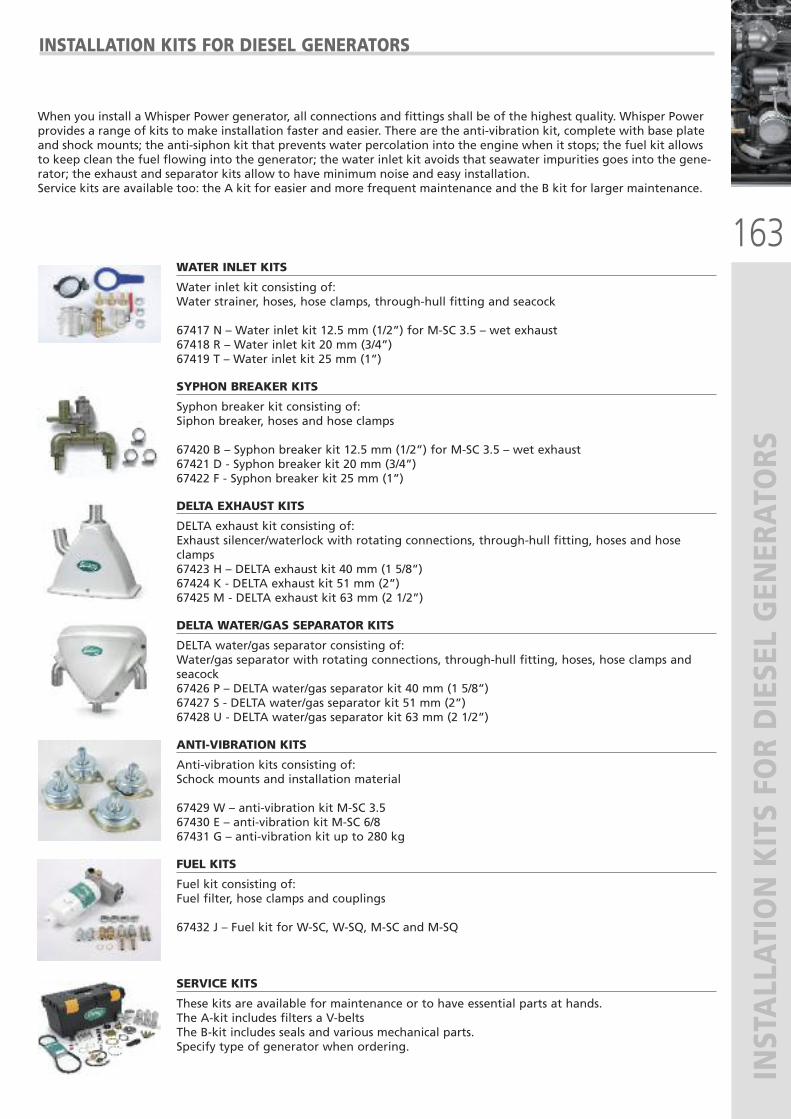
163
INSTALLATION KITS FOR DIESEL GENERATORS
INSTALLATION KITS FOR DIESEL GENERATORS
When you install a Whisper Power generator, all connections and fittings shall be of the highest quality. Whisper Powerprovides a range of kits to make installation faster and easier. There are the anti-vibration kit, complete with base plateand shock mounts; the anti-siphon kit that prevents water percolation into the engine when it stops; the fuel kit allowsto keep clean the fuel flowing into the generator; the water inlet kit avoids that seawater impurities goes into the gene-rator; the exhaust and separator kits allow to have minimum noise and easy installation.Service kits are available too: the A kit for easier and more frequent maintenance and the B kit for larger maintenance.
WATER INLET KITS
Water inlet kit consisting of:Water strainer, hoses, hose clamps, through-hull fitting and seacock
67417 N – Water inlet kit 12.5 mm (1/2”) for M-SC 3.5 – wet exhaust67418 R – Water inlet kit 20 mm (3/4”)67419 T – Water inlet kit 25 mm (1”)
SYPHON BREAKER KITS
Syphon breaker kit consisting of:Siphon breaker, hoses and hose clamps
67420 B – Syphon breaker kit 12.5 mm (1/2”) for M-SC 3.5 – wet exhaust67421 D - Syphon breaker kit 20 mm (3/4”)67422 F - Syphon breaker kit 25 mm (1”)
DELTA EXHAUST KITS
DELTA exhaust kit consisting of:Exhaust silencer/waterlock with rotating connections, through-hull fitting, hoses and hoseclamps67423 H – DELTA exhaust kit 40 mm (1 5/8”)67424 K - DELTA exhaust kit 51 mm (2”)67425 M - DELTA exhaust kit 63 mm (2 1/2”)
DELTA WATER/GAS SEPARATOR KITS
DELTA water/gas separator consisting of:Water/gas separator with rotating connections, through-hull fitting, hoses, hose clamps andseacock67426 P – DELTA water/gas separator kit 40 mm (1 5/8”)67427 S - DELTA water/gas separator kit 51 mm (2”)67428 U - DELTA water/gas separator kit 63 mm (2 1/2”)
ANTI-VIBRATION KITS
Anti-vibration kits consisting of:Schock mounts and installation material
67429 W – anti-vibration kit M-SC 3.567430 E – anti-vibration kit M-SC 6/867431 G – anti-vibration kit up to 280 kg
FUEL KITS
Fuel kit consisting of:Fuel filter, hose clamps and couplings
67432 J – Fuel kit for W-SC, W-SQ, M-SC and M-SQ
SERVICE KITS
These kits are available for maintenance or to have essential parts at hands.The A-kit includes filters a V-beltsThe B-kit includes seals and various mechanical parts.Specify type of generator when ordering.
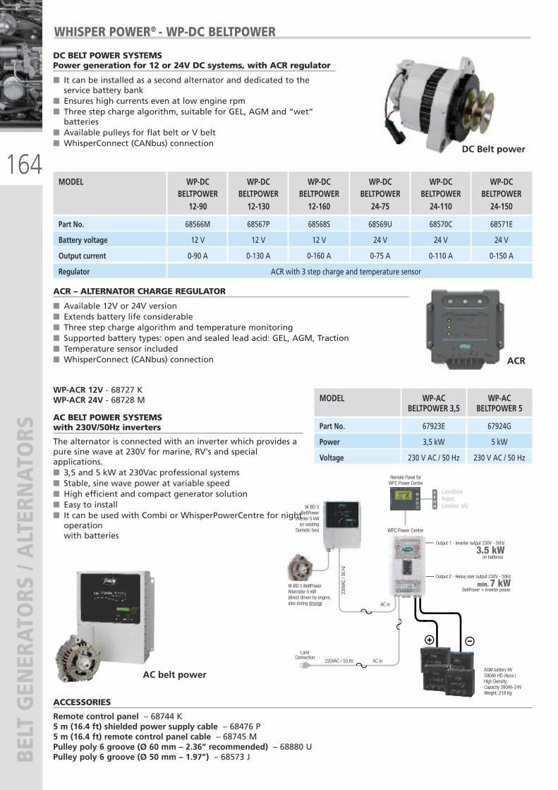
164
BELT GENERATORS / ALTERNATORS
ACR – ALTERNATOR CHARGE REGULATOR
� Available 12V or 24V version� Extends battery life considerable� Three step charge algorithm and temperature monitoring� Supported battery types: open and sealed lead acid: GEL, AGM, Traction� Temperature sensor included� WhisperConnect (CANbus) connection
WP-ACR 12V - 68727 KWP-ACR 24V - 68728 M
ACCESSORIES
Remote control panel – 68744 K5 m (16.4 ft) shielded power supply cable – 68476 P5 m (16.4 ft) remote control panel cable – 68745 MPulley poly 6 groove (Ø 60 mm – 2.36” recommended) – 68880 UPulley poly 6 groove (Ø 50 mm – 1.97”) – 68573 J
AC BELT POWER SYSTEMSwith 230V/50Hz inverters
The alternator is connected with an inverter which provides apure sine wave at 230V for marine, RV’s and specialapplications.� 3,5 and 5 kW at 230Vac professional systems � Stable, sine wave power at variable speed� High efficient and compact generator solution� Easy to install� It can be used with Combi or WhisperPowerCentre for nightoperation with batteries
ACR
AC belt power
MODEL WP-AC WP-ACBELTPOWER 3,5 BELTPOWER 5
Part No. 67923E 67924G
Power 3,5 kW 5 kW
Voltage 230 V AC / 50 Hz 230 V AC / 50 Hz
461216
+ –
LandlineInput Limiter (A)
W-BD 5 BeltPower Alternator 5 kW(direct driven by engine, also during driving)
AC in
AC in
WPC Power Centre
230V
AC /
50 H
z
W-BD 5BeltPower
Inverter 5 kW(or existing
Dometic box)
230VAC / 50 Hz
Output 2 - Heavy user output 230V - 50Hz
on batteries
BeltPower + Inverter powermin. 7 kW
3.5 kW
Land Connection
Remote Panel for WPC Power Centre
AGM battery 6V 390Ah HD (4pcs.)High Density, Capacity 390Ah-24VWeight: 218 Kg
Output 1 - Inverter output 230V - 50Hz
DC BELT POWER SYSTEMSPower generation for 12 or 24V DC systems, with ACR regulator
� It can be installed as a second alternator and dedicated to theservice battery bank
� Ensures high currents even at low engine rpm� Three step charge algorithm, suitable for GEL, AGM and “wet”batteries
� Available pulleys for flat belt or V belt� WhisperConnect (CANbus) connection
DC Belt power
MODEL WP-DC WP-DC WP-DC WP-DC WP-DC WP-DCBELTPOWER BELTPOWER BELTPOWER BELTPOWER BELTPOWER BELTPOWER
12-90 12-130 12-160 24-75 24-110 24-150
Part No. 68566M 68567P 68568S 68569U 68570C 68571E
Battery voltage 12 V 12 V 12 V 24 V 24 V 24 V
Output current 0-90 A 0-130 A 0-160 A 0-75 A 0-110 A 0-150 A
Regulator ACR with 3 step charge and temperature sensor
WHISPER POWER® - WP-DC BELTPOWER
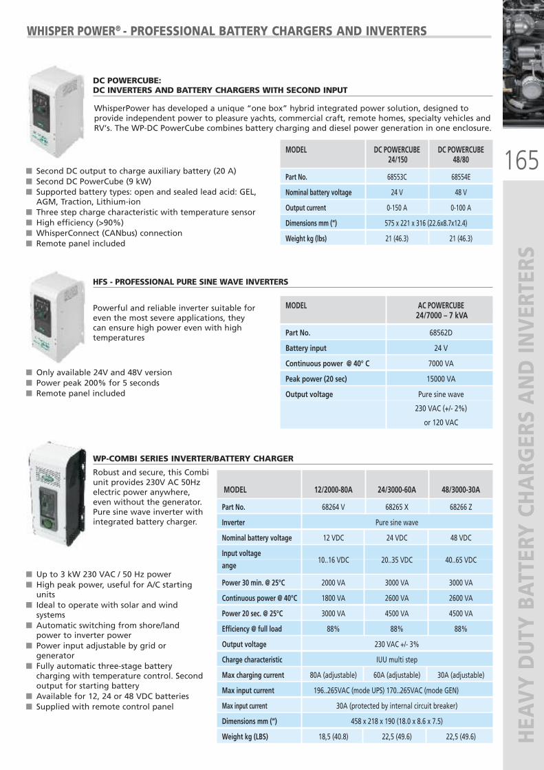
165
HEAVY DUTY BATTERY CHARG
ERS AND IN
VERTERS
DC POWERCUBE: DC INVERTERS AND BATTERY CHARGERS WITH SECOND INPUT
� Second DC output to charge auxiliary battery (20 A)� Second DC PowerCube (9 kW)� Supported battery types: open and sealed lead acid: GEL,AGM, Traction, Lithium-ion
� Three step charge characteristic with temperature sensor� High efficiency (>90%)� WhisperConnect (CANbus) connection� Remote panel included
WHISPER POWER® - PROFESSIONAL BATTERY CHARGERS AND INVERTERS
MODEL DC POWERCUBE DC POWERCUBE24/150 48/80
Part No. 68553C 68554E
Nominal battery voltage 24 V 48 V
Output current 0-150 A 0-100 A
Dimensions mm (“) 575 x 221 x 316 (22.6x8.7x12.4)
Weight kg (lbs) 21 (46.3) 21 (46.3)
MODEL 12/2000-80A 24/3000-60A 48/3000-30A
Part No. 68264 V 68265 X 68266 Z
Inverter Pure sine wave
Nominal battery voltage 12 VDC 24 VDC 48 VDC
Input voltage
ange10..16 VDC 20..35 VDC 40..65 VDC
Power 30 min. @ 25°C 2000 VA 3000 VA 3000 VA
Continuous power @ 40°C 1800 VA 2600 VA 2600 VA
Power 20 sec. @ 25°C 3000 VA 4500 VA 4500 VA
Efficiency @ full load 88% 88% 88%
Output voltage 230 VAC +/- 3%
Charge characteristic IUU multi step
Max charging current 80A (adjustable) 60A (adjustable) 30A (adjustable)
Max input current 196..265VAC (mode UPS) 170..265VAC (mode GEN)
Max input current 30A (protected by internal circuit breaker)
Dimensions mm (“) 458 x 218 x 190 (18.0 x 8.6 x 7.5)
Weight kg (LBS) 18,5 (40.8) 22,5 (49.6) 22,5 (49.6)
HFS - PROFESSIONAL PURE SINE WAVE INVERTERS
Powerful and reliable inverter suitable foreven the most severe applications, theycan ensure high power even with hightemperatures
� Only available 24V and 48V version� Power peak 200% for 5 seconds� Remote panel included
MODEL AC POWERCUBE 24/7000 – 7 kVA
Part No. 68562D
Battery input 24 V
Continuous power @ 40° C 7000 VA
Peak power (20 sec) 15000 VA
Output voltage Pure sine wave
230 VAC (+/- 2%)
or 120 VAC
WP-COMBI SERIES INVERTER/BATTERY CHARGER
Robust and secure, this Combi unit provides 230V AC 50Hz electric power anywhere, even without the generator. Pure sine wave inverter with integrated battery charger.
� Up to 3 kW 230 VAC / 50 Hz power� High peak power, useful for A/C startingunits
� Ideal to operate with solar and windsystems
� Automatic switching from shore/landpower to inverter power
� Power input adjustable by grid orgenerator
� Fully automatic three-stage batterycharging with temperature control. Secondoutput for starting battery
� Available for 12, 24 or 48 VDC batteries� Supplied with remote control panel
WhisperPower has developed a unique “one box” hybrid integrated power solution, designed toprovide independent power to pleasure yachts, commercial craft, remote homes, specialty vehicles andRV’s. The WP-DC PowerCube combines battery charging and diesel power generation in one enclosure.
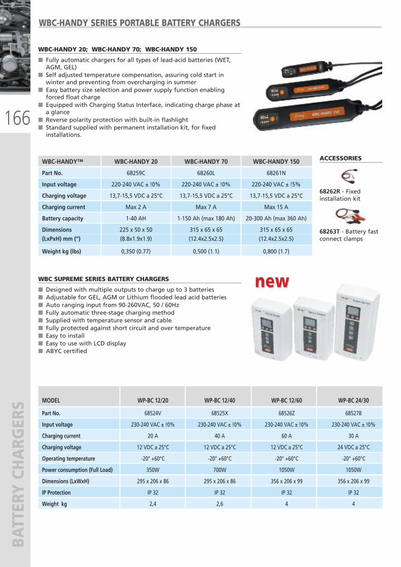
166
BATTERY CHARG
ERS
WBC-HANDY 20; WBC-HANDY 70; WBC-HANDY 150
� Fully automatic chargers for all types of lead-acid batteries (WET,AGM, GEL)
� Self adjusted temperature compensation, assuring cold start inwinter and preventing from overcharging in summer
� Easy battery size selection and power supply function enablingforced float charge
� Equipped with Charging Status Interface, indicating charge phase ata glance
� Reverse polarity protection with built-in flashlight� Standard supplied with permanent installation kit, for fixedinstallations.
WBC-HANDY SERIES PORTABLE BATTERY CHARGERS
MODEL WP-BC 12/20 WP-BC 12/40 WP-BC 12/60 WP-BC 24/30
Part No. 68524V 68525X 68526Z 68527B
Input voltage 230-240 VAC ± !0% 230-240 VAC ± !0% 230-240 VAC ± !0% 230-240 VAC ± !0%
Charging current 20 A 40 A 60 A 30 A
Charging voltage 12 VDC a 25°C 12 VDC a 25°C 12 VDC a 25°C 24 VDC a 25°C
Operating temperature -20° +60°C -20° +60°C -20° +60°C -20° +60°C
Power consumption (Full Load) 350W 700W 1050W 1050W
Dimensions (LxWxH) 295 x 206 x 86 295 x 206 x 86 356 x 206 x 99 356 x 206 x 99
IP Protection IP 32 IP 32 IP 32 IP 32
Weight kg 2,4 2,6 4 4
WBC SUPREME SERIES BATTERY CHARGERS
� Designed with multiple outputs to charge up to 3 batteries� Adjustable for GEL, AGM or Lithium flooded lead acid batteries� Auto ranging input from 90-260VAC, 50 / 60Hz� Fully automatic three-stage charging method � Supplied with temperature sensor and cable� Fully protected against short circuit and over temperature� Easy to install� Easy to use with LCD display� ABYC certified
WBC-HANDY™ WBC-HANDY 20 WBC-HANDY 70 WBC-HANDY 150
Part No. 68259C 68260L 68261N
Input voltage 220-240 VAC ± !0% 220-240 VAC ± !0% 220-240 VAC ± !5%
Charging voltage 13,7-15,5 VDC a 25°C 13,7-15,5 VDC a 25°C 13,7-15,5 VDC a 25°C
Charging current Max 2 A Max 7 A Max 15 A
Battery capacity 1-40 AH 1-150 Ah (max 180 Ah) 20-300 Ah (max 360 Ah)
Dimensions 225 x 50 x 50 315 x 65 x 65 315 x 65 x 65
(LxPxH) mm (“) (8.8x1.9x1.9) (12.4x2.5x2.5) (12.4x2.5x2.5)
Weight kg (lbs) 0,350 (0.77) 0,500 (1.1) 0,800 (1.7)
ACCESSORIES
68262R - Fixedinstallation kit
68263T - Battery fastconnect clamps
new new
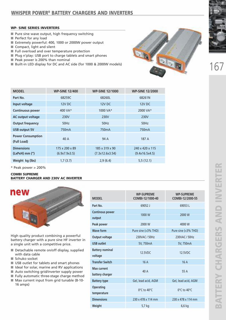
167
BATTERY CHARG
ERS AND IN
VERTER
WP- SINE SERIES INVERTERS
� Pure sine wave output, high frequency switching� Perfect for any load� Extremely powerful: 400, 1000 or 2000W power output� Compact, light and silent � Full overload and over temperature protection� Plug n’play: USB port to charge tablets and smart phones� Peak power is 200% than nominal� Built-in LED display for DC and AC side (for 1000 & 2000W models)
High quality product combining a powerfulbattery charger with a pure sine HF inverter ina single unit with a competitive price.
� Detachable remote on/off display, suppliedwith data cable
� Schuko socket� USB outlet for tablets and smart phones� Ideal for solar, marine and RV applications � Auto switching grid/inverter supply power� Fully automatic three-stage charge method � Max current input from grid tunable (8-10-16 amps)
WHISPER POWER® BATTERY CHARGERS AND INVERTERS
MODEL WP-SINE 12/400 WP-SINE 12/1000 WP-SINE 12/2000
Part No. 68259C 68260L 68261N
Input voltage 12V DC 12V DC 12V DC
Continuous power 400 VA* 1000 VA* 2000 VA*
AC output voltage 230V 230V 230V
Output frequency 50Hz 50Hz 50Hz
USB output 5V 750mA 750mA 750mA
Power Consumption
(Full Load)40 A 94 A 187 A
Dimensions 175 x 200 x 89 185 x 319 x 90 240 x 420 x 115
(LxPxH) mm (“) (6.9x7.9x3.5) (7.3x12.6x3.54) (9.4x16.5x4.5)
Weight kg (lbs) 1,7 (3.7) 2,9 (6.4) 5,5 (12.1)
* Peak power > 200%
WP-SUPREME WP-SUPREMEMODEL COMBI-12/1000-40 COMBI-12/2000-55
Part No. 69052 J 69053 L
Continous power
output1000 W 2000 W
Peak power 2000 W 4000 W
Wave form Pure sine (<3% THD) Pure sine (<3% THD)
Output voltage 230VAC / 50Hz 230VAC / 50Hz
USB outlet 5V, 750mA 5V, 750mA
Battery nominal
voltage12.5VDC 12.5VDC
Transfer Switch 16 A 16 A
Max current
battery charger40 A 55 A
Battery type Gel, lead acid, AGM Gel, lead acid, AGM
Operating
temperature 0°C to 40°C 0°C to 40°C
Dimensions 230 x 478 x 114 mm 230 x 478 x 114 mm
Weight 5,7 kg 6,6 kg
new new
COMBI SUPREMEBATTERY CHARGER AND 230V AC INVERTER
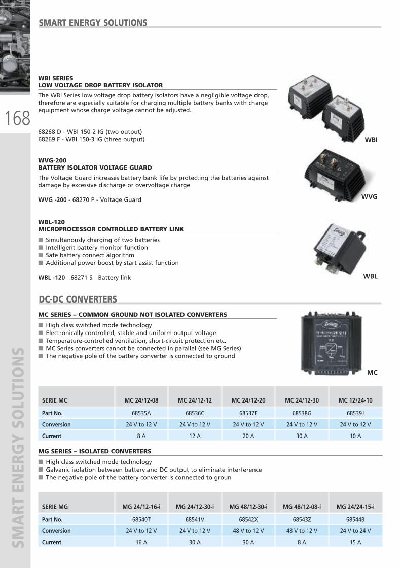
168
SMART ENERGY SOLUTIONS
WBI
WBI SERIESLOW VOLTAGE DROP BATTERY ISOLATOR
The WBI Series low voltage drop battery isolators have a negligible voltage drop,therefore are especially suitable for charging multiple battery banks with chargeequipment whose charge voltage cannot be adjusted.
68268 D - WBI 150-2 IG (two output)68269 F - WBI 150-3 IG (three output)
SMART ENERGY SOLUTIONS
WVG
WVG-200BATTERY ISOLATOR VOLTAGE GUARD
The Voltage Guard increases battery bank life by protecting the batteries againstdamage by excessive discharge or overvoltage charge
WVG -200 - 68270 P - Voltage Guard
WBL
WBL-120MICROPROCESSOR CONTROLLED BATTERY LINK
� Simultanously charging of two batteries� Intelligent battery monitor function� Safe battery connect algorithm� Additional power boost by start assist function
WBL -120 - 68271 S - Battery link
MC
MC SERIES – COMMON GROUND NOT ISOLATED CONVERTERS
� High class switched mode technology� Electronically controlled, stable and uniform output voltage� Temperature-controlled ventilation, short-circuit protection etc.� MC Series converters cannot be connected in parallel (see MG Series)� The negative pole of the battery converter is connected to ground
DC-DC CONVERTERS
MG SERIES – ISOLATED CONVERTERS
� High class switched mode technology� Galvanic isolation between battery and DC output to eliminate interference� The negative pole of the battery converter is connected to groun
SERIE MC MC 24/12-08 MC 24/12-12 MC 24/12-20 MC 24/12-30 MC 12/24-10
Part No. 68535A 68536C 68537E 68538G 68539J
Conversion 24 V to 12 V 24 V to 12 V 24 V to 12 V 24 V to 12 V 24 V to 12 V
Current 8 A 12 A 20 A 30 A 10 A
SERIE MG MG 24/12-16-i MG 24/12-30-i MG 48/12-30-i MG 48/12-08-i MG 24/24-15-i
Part No. 68540T 68541V 68542X 68543Z 68544B
Conversion 24 V to 12 V 24 V to 12 V 48 V to 12 V 48 V to 12 V 24 V to 24 V
Current 16 A 30 A 30 A 8 A 15 A
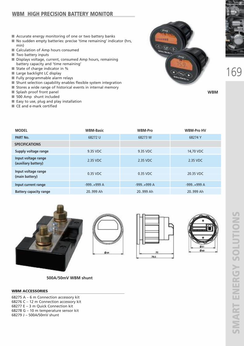
169
SMART ENERGY SOLUTIONS
WBM HIGH PRECISION BATTERY MONITOR
� Accurate energy monitoring of one or two battery banks� No sudden empty batteries: precise ‘time remaining’ indicator (hrs,min)
� Calculation of Amp hours consumed � Two battery inputs� Displays voltage, current, consumed Amp hours, remainingbattery capacity and ‘time remaining’
� State of charge indicator in %� Large backlight LC display� Fully programmable alarm relays� Shunt selection capability enables flexible system integration� Stores a wide range of historical events in internal memory� Splash proof front panel� 500 Amp shunt included� Easy to use, plug and play installation� CE and e-mark certified
WBM
500A/50mV WBM shunt
WBM ACCESSORIES
68275 A – 6 m Connection accessory kit68276 C – 12 m Connection accessory kit68277 E – 3 m Quick Connection kit68278 G – 10 m temperature sensor kit68279 J – 500A/50mV shunt
MODEL WBM-Basic WBM-Pro WBM-Pro HV
PART No. 68272 U 68273 W 68274 Y
SPECIFICATIONS
Supply voltage range 9.35 VDC 9.35 VDC 14,70 VDC
Input voltage range (auxiliary battery)
2.35 VDC 2.35 VDC 2.35 VDC
Input voltage range (main battery)
0.35 VDC 0.35 VDC 20.35 VDC
Input current range -999..+999 A -999..+999 A -999..+999 A
Battery capacity range 20..999 Ah 20..999 Ah 20..999 Ah
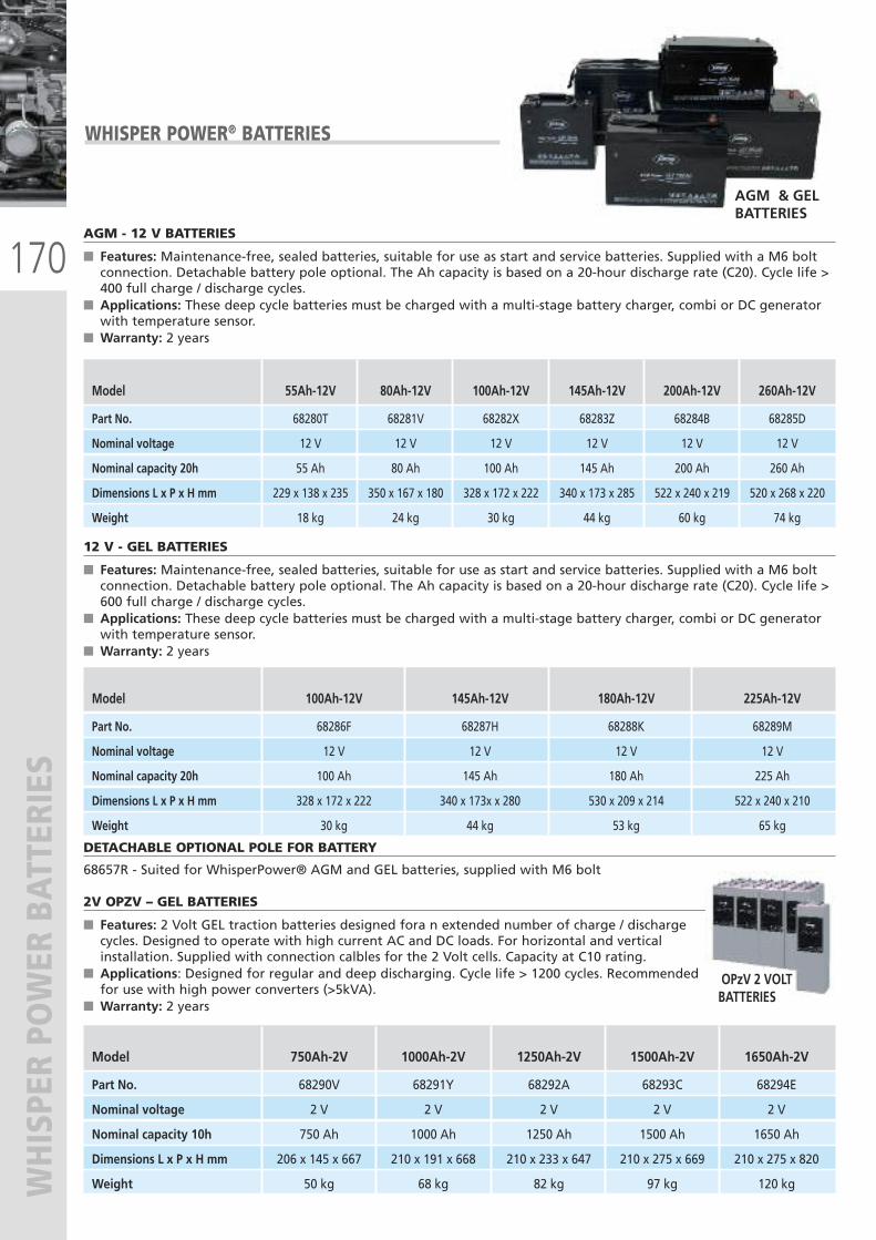
170
WHISPER POWER BATTERIES
WHISPER POWER® BATTERIES
AGM & GELBATTERIES
DETACHABLE OPTIONAL POLE FOR BATTERY
68657R - Suited for WhisperPower® AGM and GEL batteries, supplied with M6 bolt
Model 750Ah-2V 1000Ah-2V 1250Ah-2V 1500Ah-2V 1650Ah-2V
Part No. 68290V 68291Y 68292A 68293C 68294E
Nominal voltage 2 V 2 V 2 V 2 V 2 V
Nominal capacity 10h 750 Ah 1000 Ah 1250 Ah 1500 Ah 1650 Ah
Dimensions L x P x H mm 206 x 145 x 667 210 x 191 x 668 210 x 233 x 647 210 x 275 x 669 210 x 275 x 820
Weight 50 kg 68 kg 82 kg 97 kg 120 kg
2V OPZV – GEL BATTERIES
� Features: 2 Volt GEL traction batteries designed fora n extended number of charge / dischargecycles. Designed to operate with high current AC and DC loads. For horizontal and verticalinstallation. Supplied with connection calbles for the 2 Volt cells. Capacity at C10 rating.
� Applications: Designed for regular and deep discharging. Cycle life > 1200 cycles. Recommendedfor use with high power converters (>5kVA).
� Warranty: 2 years
OPzV 2 VOLTBATTERIES
AGM - 12 V BATTERIES
� Features: Maintenance-free, sealed batteries, suitable for use as start and service batteries. Supplied with a M6 boltconnection. Detachable battery pole optional. The Ah capacity is based on a 20-hour discharge rate (C20). Cycle life >400 full charge / discharge cycles.
� Applications: These deep cycle batteries must be charged with a multi-stage battery charger, combi or DC generatorwith temperature sensor.
� Warranty: 2 years
Model 55Ah-12V 80Ah-12V 100Ah-12V 145Ah-12V 200Ah-12V 260Ah-12V
Part No. 68280T 68281V 68282X 68283Z 68284B 68285D
Nominal voltage 12 V 12 V 12 V 12 V 12 V 12 V
Nominal capacity 20h 55 Ah 80 Ah 100 Ah 145 Ah 200 Ah 260 Ah
Dimensions L x P x H mm 229 x 138 x 235 350 x 167 x 180 328 x 172 x 222 340 x 173 x 285 522 x 240 x 219 520 x 268 x 220
Weight 18 kg 24 kg 30 kg 44 kg 60 kg 74 kg
12 V - GEL BATTERIES
� Features: Maintenance-free, sealed batteries, suitable for use as start and service batteries. Supplied with a M6 boltconnection. Detachable battery pole optional. The Ah capacity is based on a 20-hour discharge rate (C20). Cycle life >600 full charge / discharge cycles.
� Applications: These deep cycle batteries must be charged with a multi-stage battery charger, combi or DC generatorwith temperature sensor.
� Warranty: 2 years
Model 100Ah-12V 145Ah-12V 180Ah-12V 225Ah-12V
Part No. 68286F 68287H 68288K 68289M
Nominal voltage 12 V 12 V 12 V 12 V
Nominal capacity 20h 100 Ah 145 Ah 180 Ah 225 Ah
Dimensions L x P x H mm 328 x 172 x 222 340 x 173x x 280 530 x 209 x 214 522 x 240 x 210
Weight 30 kg 44 kg 53 kg 65 kg
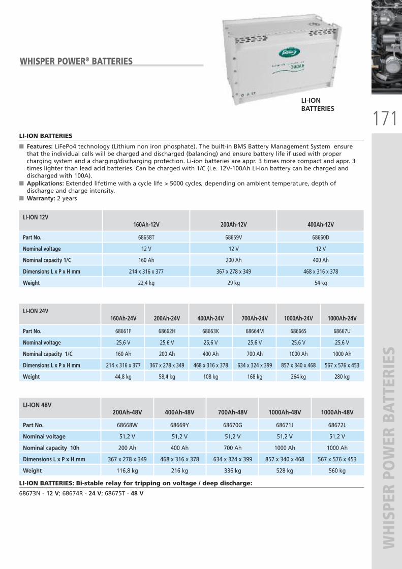
171
WHISPER POWER BATTERIES
WHISPER POWER® BATTERIES
LI-ION BATTERIES
LI-ION 48V 200Ah-48V 400Ah-48V 700Ah-48V 1000Ah-48V 1000Ah-48V
Part No. 68668W 68669Y 68670G 68671J 68672L
Nominal voltage 51,2 V 51,2 V 51,2 V 51,2 V 51,2 V
Nominal capacity 10h 200 Ah 400 Ah 700 Ah 1000 Ah 1000 Ah
Dimensions L x P x H mm 367 x 278 x 349 468 x 316 x 378 634 x 324 x 399 857 x 340 x 468 567 x 576 x 453
Weight 116,8 kg 216 kg 336 kg 528 kg 560 kg
LI-ION 24V 160Ah-24V 200Ah-24V 400Ah-24V 700Ah-24V 1000Ah-24V 1000Ah-24V
Part No. 68661F 68662H 68663K 68664M 68666S 68667U
Nominal voltage 25,6 V 25,6 V 25,6 V 25,6 V 25,6 V 25,6 V
Nominal capacity 1/C 160 Ah 200 Ah 400 Ah 700 Ah 1000 Ah 1000 Ah
Dimensions L x P x H mm 214 x 316 x 377 367 x 278 x 349 468 x 316 x 378 634 x 324 x 399 857 x 340 x 468 567 x 576 x 453
Weight 44,8 kg 58,4 kg 108 kg 168 kg 264 kg 280 kg
LI-ION BATTERIES: Bi-stable relay for tripping on voltage / deep discharge:
68673N - 12 V; 68674R - 24 V; 68675T - 48 V
LI-ION BATTERIES
� Features: LiFePo4 technology (Lithium non iron phosphate). The built-in BMS Battery Management System ensurethat the individual cells will be charged and discharged (balancing) and ensure battery life if used with propercharging system and a charging/discharging protection. Li-ion batteries are appr. 3 times more compact and appr. 3times lighter than lead acid batteries. Can be charged with 1/C (i.e. 12V-100Ah Li-ion battery can be charged anddischarged with 100A).
� Applications: Extended lifetime with a cycle life > 5000 cycles, depending on ambient temperature, depth ofdischarge and charge intensity.
� Warranty: 2 years
LI-ION 12V 160Ah-12V 200Ah-12V 400Ah-12V
Part No. 68658T 68659V 68660D
Nominal voltage 12 V 12 V 12 V
Nominal capacity 1/C 160 Ah 200 Ah 400 Ah
Dimensions L x P x H mm 214 x 316 x 377 367 x 278 x 349 468 x 316 x 378
Weight 22,4 kg 29 kg 54 kg
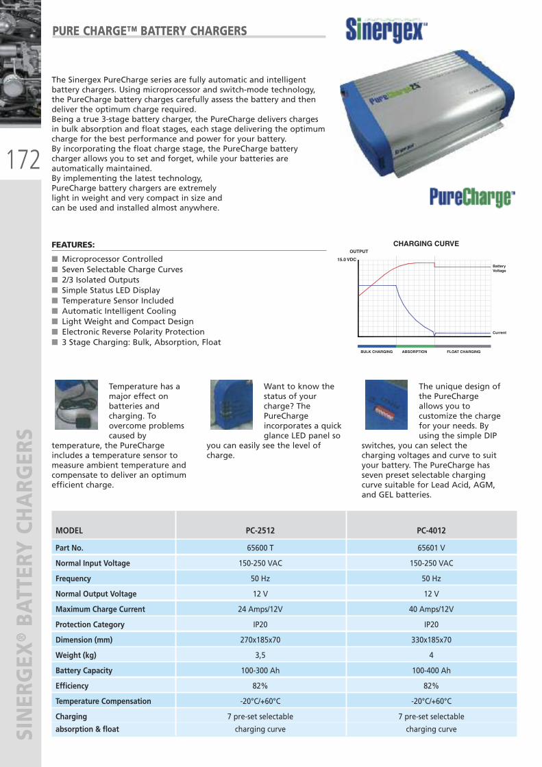
172
SINERGEX
®BATTERY CHARG
ERS
Temperature has amajor effect onbatteries andcharging. Toovercome problemscaused by
temperature, the PureChargeincludes a temperature sensor tomeasure ambient temperature andcompensate to deliver an optimumefficient charge.
PURE CHARGE™ BATTERY CHARGERS
The Sinergex PureCharge series are fully automatic and intelligentbattery chargers. Using microprocessor and switch-mode technology,the PureCharge battery charges carefully assess the battery and thendeliver the optimum charge required.Being a true 3-stage battery charger, the PureCharge delivers chargesin bulk absorption and float stages, each stage delivering the optimumcharge for the best performance and power for your battery. By incorporating the float charge stage, the PureCharge batterycharger allows you to set and forget, while your batteries areautomatically maintained.By implementing the latest technology,PureCharge battery chargers are extremelylight in weight and very compact in size andcan be used and installed almost anywhere.
FEATURES:
� Microprocessor Controlled� Seven Selectable Charge Curves� 2/3 Isolated Outputs� Simple Status LED Display� Temperature Sensor Included� Automatic Intelligent Cooling� Light Weight and Compact Design� Electronic Reverse Polarity Protection� 3 Stage Charging: Bulk, Absorption, Float
BULK CHARGING
OUTPUT
15.0 VDC
CHARGING CURVE
ABSORPTION FLOAT CHARGING
Current
Battery Voltage
MODEL PC-2512 PC-4012
Part No. 65600 T 65601 V
Normal Input Voltage 150-250 VAC 150-250 VAC
Frequency 50 Hz 50 Hz
Normal Output Voltage 12 V 12 V
Maximum Charge Current 24 Amps/12V 40 Amps/12V
Protection Category IP20 IP20
Dimension (mm) 270x185x70 330x185x70
Weight (kg) 3,5 4
Battery Capacity 100-300 Ah 100-400 Ah
Efficiency 82% 82%
Temperature Compensation -20°C/+60°C -20°C/+60°C
Charging 7 pre-set selectable 7 pre-set selectable
absorption & float charging curve charging curve
Want to know thestatus of yourcharge? ThePureChargeincorporates a quickglance LED panel so
you can easily see the level ofcharge.
The unique design ofthe PureChargeallows you tocustomize the chargefor your needs. Byusing the simple DIP
switches, you can select thecharging voltages and curve to suityour battery. The PureCharge hasseven preset selectable chargingcurve suitable for Lead Acid, AGM,and GEL batteries.
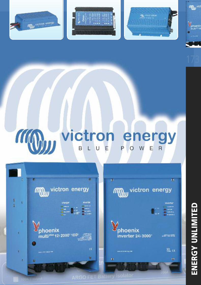
173
ENERGY UNLIMITED
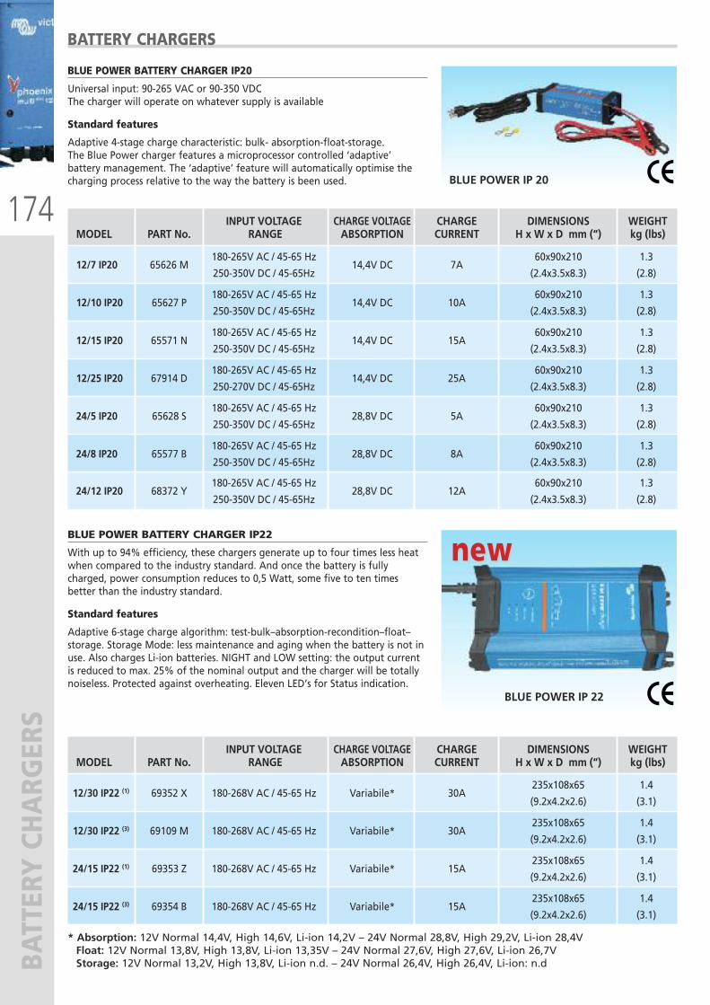
174
BATTERY CHARG
ERS
BLUE POWER BATTERY CHARGER IP20
Universal input: 90-265 VAC or 90-350 VDCThe charger will operate on whatever supply is available
Standard features
Adaptive 4-stage charge characteristic: bulk- absorption-float-storage.The Blue Power charger features a microprocessor controlled ‘adaptive’battery management. The ‘adaptive’ feature will automatically optimise thecharging process relative to the way the battery is been used.
BATTERY CHARGERS
BLUE POWER IP 20
INPUT VOLTAGE CHARGE VOLTAGE CHARGE DIMENSIONS WEIGHT MODEL PART No. RANGE ABSORPTION CURRENT H x W x D mm (“) kg (lbs)
180-265V AC / 45-65 Hz 60x90x210 1.3
12/7 IP20 65626 M
250-350V DC / 45-65Hz 14,4V DC 7A
(2.4x3.5x8.3) (2.8)
180-265V AC / 45-65 Hz 60x90x210 1.3
12/10 IP20 65627 P
250-350V DC / 45-65Hz 14,4V DC 10A
(2.4x3.5x8.3) (2.8)
180-265V AC / 45-65 Hz 60x90x210 1.3
12/15 IP20 65571 N
250-350V DC / 45-65Hz 14,4V DC 15A
(2.4x3.5x8.3) (2.8)
180-265V AC / 45-65 Hz 60x90x210 1.3
12/25 IP20 67914 D
250-270V DC / 45-65Hz 14,4V DC 25A
(2.4x3.5x8.3) (2.8)
180-265V AC / 45-65 Hz 60x90x210 1.3
24/5 IP20 65628 S
250-350V DC / 45-65Hz 28,8V DC 5A
(2.4x3.5x8.3) (2.8)
180-265V AC / 45-65 Hz 60x90x210 1.3
24/8 IP20 65577 B
250-350V DC / 45-65Hz 28,8V DC 8A
(2.4x3.5x8.3) (2.8)
180-265V AC / 45-65 Hz 60x90x210 1.3
24/12 IP20 68372 Y
250-350V DC / 45-65Hz 28,8V DC 12A
(2.4x3.5x8.3) (2.8)
BLUE POWER BATTERY CHARGER IP22
With up to 94% efficiency, these chargers generate up to four times less heatwhen compared to the industry standard. And once the battery is fullycharged, power consumption reduces to 0,5 Watt, some five to ten timesbetter than the industry standard.
Standard features
Adaptive 6-stage charge algorithm: test-bulk–absorption-recondition–float–storage. Storage Mode: less maintenance and aging when the battery is not inuse. Also charges Li-ion batteries. NIGHT and LOW setting: the output currentis reduced to max. 25% of the nominal output and the charger will be totallynoiseless. Protected against overheating. Eleven LED’s for Status indication.
BLUE POWER IP 22
INPUT VOLTAGE CHARGE VOLTAGE CHARGE DIMENSIONS WEIGHT MODEL PART No. RANGE ABSORPTION CURRENT H x W x D mm (“) kg (lbs)
235x108x65 1.4
12/30 IP22 (1) 69352 X
180-268V AC / 45-65 Hz
Variabile* 30A
(9.2x4.2x2.6) (3.1)
235x108x65 1.4
12/30 IP22 (3) 69109 M
180-268V AC / 45-65 Hz
Variabile* 30A
(9.2x4.2x2.6) (3.1)
235x108x65 1.4
24/15 IP22 (1) 69353 Z
180-268V AC / 45-65 Hz
Variabile* 15A
(9.2x4.2x2.6) (3.1)
235x108x65 1.4
24/15 IP22 (3) 69354 B
180-268V AC / 45-65 Hz
Variabile* 15A
(9.2x4.2x2.6) (3.1)
* Absorption: 12V Normal 14,4V, High 14,6V, Li-ion 14,2V – 24V Normal 28,8V, High 29,2V, Li-ion 28,4V Float: 12V Normal 13,8V, High 13,8V, Li-ion 13,35V – 24V Normal 27,6V, High 27,6V, Li-ion 26,7V Storage: 12V Normal 13,2V, High 13,8V, Li-ion n.d. – 24V Normal 26,4V, High 26,4V, Li-ion: n.d
new new
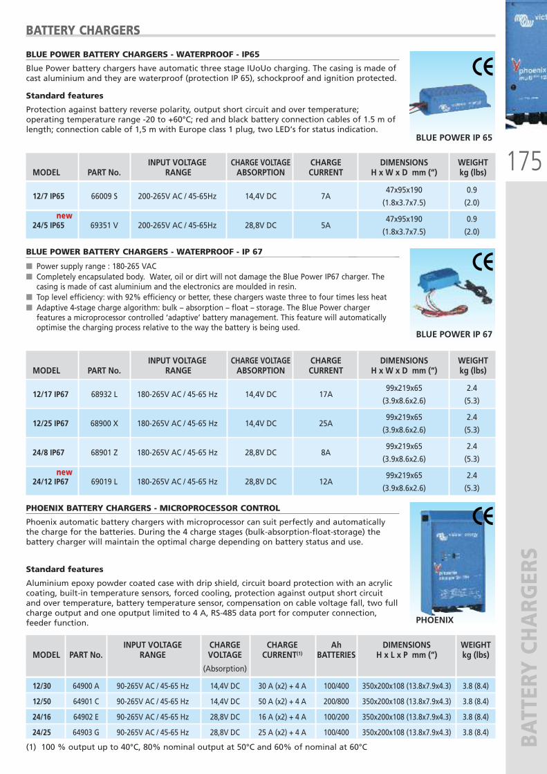
175
BATTERY CHARG
ERS
BLUE POWER BATTERY CHARGERS - WATERPROOF - IP65
Blue Power battery chargers have automatic three stage IUoUo charging. The casing is made ofcast aluminium and they are waterproof (protection IP 65), schockproof and ignition protected.
Standard features
Protection against battery reverse polarity, output short circuit and over temperature;operating temperature range -20 to +60°C; red and black battery connection cables of 1.5 m oflength; connection cable of 1,5 m with Europe class 1 plug, two LED’s for status indication.
BLUE POWER IP 65
BATTERY CHARGERS
INPUT VOLTAGE CHARGE VOLTAGE CHARGE DIMENSIONS WEIGHT MODEL PART No. RANGE ABSORPTION CURRENT H x W x D mm (“) kg (lbs)
47x95x190 0.9
12/7 IP65 66009 S
200-265V AC / 45-65Hz
14,4V DC 7A
(1.8x3.7x7.5) (2.0)
47x95x190 0.9
24/5 IP65 69351 V
200-265V AC / 45-65Hz
28,8V DC 5A
(1.8x3.7x7.5) (2.0)
BLUE POWER BATTERY CHARGERS - WATERPROOF - IP 67
� Power supply range : 180-265 VAC� Completely encapsulated body. Water, oil or dirt will not damage the Blue Power IP67 charger. Thecasing is made of cast aluminium and the electronics are moulded in resin.
� Top level efficiency: with 92% efficiency or better, these chargers waste three to four times less heat� Adaptive 4-stage charge algorithm: bulk – absorption – float – storage. The Blue Power chargerfeatures a microprocessor controlled ‘adaptive’ battery management. This feature will automaticallyoptimise the charging process relative to the way the battery is being used.
BLUE POWER IP 67
INPUT VOLTAGE CHARGE VOLTAGE CHARGE DIMENSIONS WEIGHT MODEL PART No. RANGE ABSORPTION CURRENT H x W x D mm (“) kg (lbs)
99x219x65 2.4
12/17 IP67 68932 L
180-265V AC / 45-65 Hz
14,4V DC 17A
(3.9x8.6x2.6) (5.3)
99x219x65 2.4
12/25 IP67 68900 X
180-265V AC / 45-65 Hz
14,4V DC 25A
(3.9x8.6x2.6) (5.3)
99x219x65 2.4
24/8 IP67 68901 Z
180-265V AC / 45-65 Hz
28,8V DC 8A
(3.9x8.6x2.6) (5.3)
99x219x65 2.4
24/12 IP67 69019 L
180-265V AC / 45-65 Hz
28,8V DC 12A
(3.9x8.6x2.6) (5.3)
PHOENIX BATTERY CHARGERS - MICROPROCESSOR CONTROL
Phoenix automatic battery chargers with microprocessor can suit perfectly and automaticallythe charge for the batteries. During the 4 charge stages (bulk-absorption-float-storage) thebattery charger will maintain the optimal charge depending on battery status and use.
Standard features
Aluminium epoxy powder coated case with drip shield, circuit board protection with an acryliccoating, built-in temperature sensors, forced cooling, protection against output short circuitand over temperature, battery temperature sensor, compensation on cable voltage fall, two fullcharge output and one oputput limited to 4 A, RS-485 data port for computer connection,feeder function. PHOENIX
INPUT VOLTAGE CHARGE CHARGE Ah DIMENSIONS WEIGHT MODEL PART No. RANGE VOLTAGE CURRENT(1) BATTERIES H x L x P mm (“) kg (lbs)
(Absorption)
12/30 64900 A 90-265V AC / 45-65 Hz 14,4V DC 30 A (x2) + 4 A 100/400 350x200x108 (13.8x7.9x4.3) 3.8 (8.4)
12/50 64901 C 90-265V AC / 45-65 Hz 14,4V DC 50 A (x2) + 4 A 200/800 350x200x108 (13.8x7.9x4.3) 3.8 (8.4)
24/16 64902 E 90-265V AC / 45-65 Hz 28,8V DC 16 A (x2) + 4 A 100/200 350x200x108 (13.8x7.9x4.3) 3.8 (8.4)
24/25 64903 G 90-265V AC / 45-65 Hz 28,8V DC 25 A (x2) + 4 A 100/400 350x200x108 (13.8x7.9x4.3) 3.8 (8.4)
(1) 100 % output up to 40°C, 80% nominal output at 50°C and 60% of nominal at 60°C
new new
new new
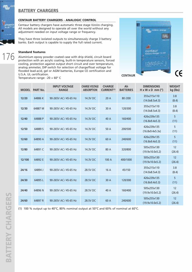
176
BATTERY CHARG
ERS
BATTERY CHARGERS
CENTAUR BATTERY CHARGERS - ANALOGIC CONTROL
Centaur battery chargers have automatic three stage IUoUo charging.All models are designed to operate all over the world without anyadjustment needed on input voltage range or frequency.
They have three isolated outputs to simultaneously charge 3 batterybanks. Each output is capable to supply the full rated current.
Standard features
Aluminium epoxy powder coated case with drip shield, circuit boardprotection with an acrylic coating, built-in temperature sensors, forcedcooling, protection against output short circuit and over temperature,analog ammeter, DIP switch for selection of charge/float voltage forflooded lead-acid, gel or AGM batteries, Europe CE certification andU.S.A. UL certification.Temperature range: -20 + 60° C
CENTAUR
(1) 100 % output up to 40°C, 80% nominal output at 50°C and 60% of nominal at 60°C.
INPUT VOLTAGE CHARGE VOLTAGE CHARGE Ah DIMENSIONS WEIGHT MODEL PART No. RANGE ABSORPTION CURRENT(1) BATTERIES H x W x D mm (“) kg (lbs)
355x215x110 3.8
12/20 64886 K 90-265V AC / 45-65 Hz 14.3V DC 20 A 80 /200
(14.0x8.5x4.3) (8.4)
355x215x110 3.8
12/30 64887 M 90-265V AC / 45-65 Hz 14.3V DC 30 A 120/300
(14.0x8.5x4.3) (8.4)
426x239x135 5
12/40 64888 P 90-265V AC / 45-65 Hz 14.3V DC 40 A 160/400
(16.8x9.4x5.3) (11)
426x239x135 5
12/50 64889 S 90-265V AC / 45-65 Hz 14.3V DC 50 A 200/500
(16.8x9.4x5.3x) (11)
426x239x135 5
12/60 64890 A 90-265V AC / 45-65 Hz 14.3V DC 60 A 240/600
(16.8x9.4x5.3) (11)
505x255x130 12
12/80 64891 C 90-265V AC / 45-65 Hz 14.3V DC 80 A 320/800
(19.9x10.0x5.2) (26.4)
505x255x130 12 12/100 64892 E 90-265V AC / 45-65 Hz 14.3V DC 100 A 400/1000
(19.9x10.0x5.2) (26.4)
355x215x110 3.8
24/16 64894 J 90-265V AC / 45-65 Hz 28.5V DC 16 A 45/150
(14.0x8.5x4.3) (8.4)
426x239x135 5
24/30 64895 L 90-265V AC / 45-65 Hz 28.5V DC 30 A 120/300
(16.8x9.4x5.3) (11)
505x255x130 12 24/40 64896 N 90-265V AC / 45-65 Hz 28.5V DC 40 A 160/400
(19.9x10.0x5.2) (26.4)
505x255x130 12
24/60 64897 R 90-265V AC / 45-65 Hz 28.5V DC 60 A 240/600
(19.9x10.0x5.2) (26.4)
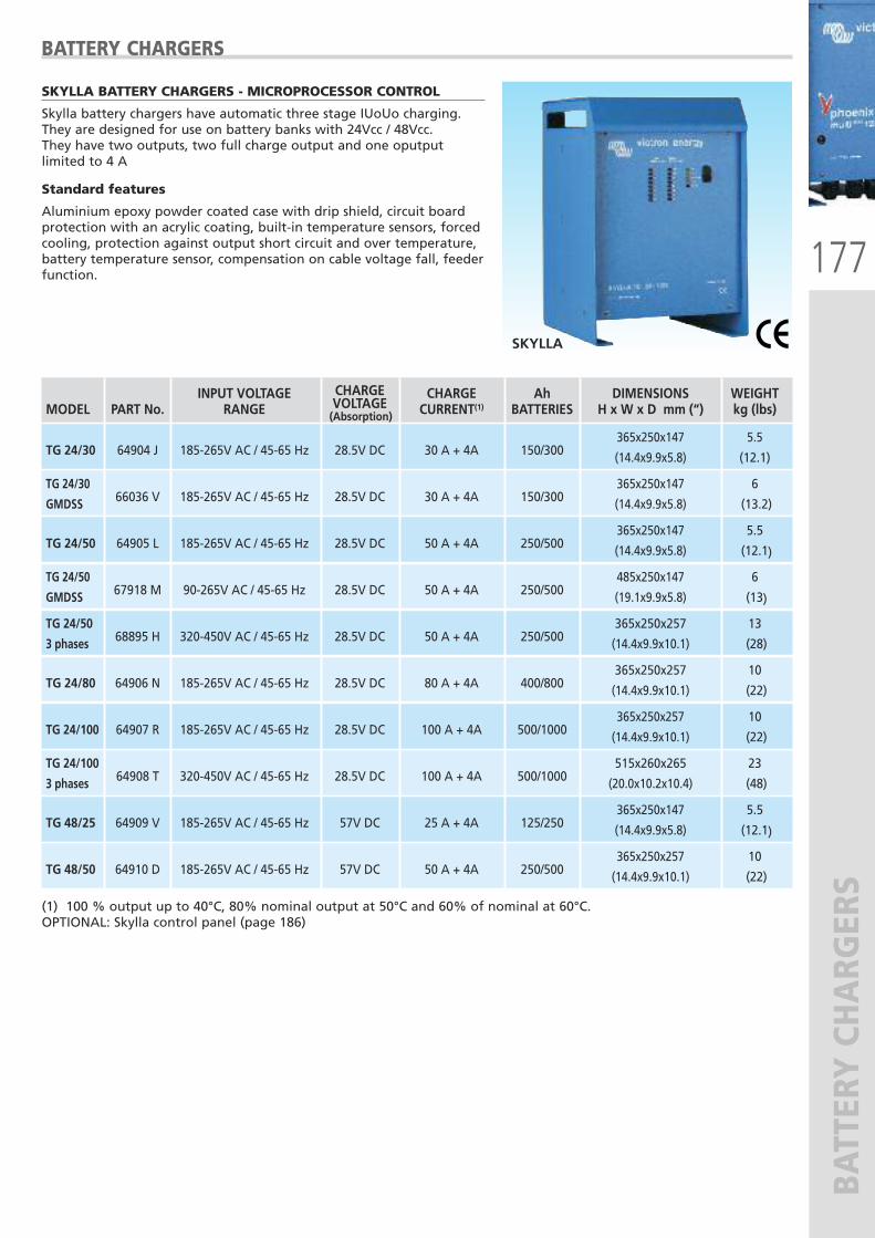
177
BATTERY CHARG
ERS
BATTERY CHARGERS
SKYLLA BATTERY CHARGERS - MICROPROCESSOR CONTROL
Skylla battery chargers have automatic three stage IUoUo charging.They are designed for use on battery banks with 24Vcc / 48Vcc.They have two outputs, two full charge output and one oputputlimited to 4 A
Standard features
Aluminium epoxy powder coated case with drip shield, circuit boardprotection with an acrylic coating, built-in temperature sensors, forcedcooling, protection against output short circuit and over temperature,battery temperature sensor, compensation on cable voltage fall, feederfunction.
SKYLLA
(1) 100 % output up to 40°C, 80% nominal output at 50°C and 60% of nominal at 60°C.OPTIONAL: Skylla control panel (page 186)
INPUT VOLTAGE CHARGE CHARGE Ah DIMENSIONS WEIGHT MODEL PART No. RANGE VOLTAGE CURRENT(1) BATTERIES H x W x D mm (“) kg (lbs)
365x250x147 5.5 TG 24/30 64904 J 185-265V AC / 45-65 Hz 28.5V DC 30 A + 4A 150/300
(14.4x9.9x5.8) (12.1)
TG 24/30 365x250x147 6
GMDSS 66036 V 185-265V AC / 45-65 Hz 28.5V DC 30 A + 4A 150/300
(14.4x9.9x5.8) (13.2)
365x250x147 5.5
TG 24/50 64905 L 185-265V AC / 45-65 Hz 28.5V DC 50 A + 4A 250/500
(14.4x9.9x5.8) (12.1)
TG 24/50 485x250x147 6
GMDSS 67918 M 90-265V AC / 45-65 Hz 28.5V DC 50 A + 4A 250/500 (19.1x9.9x5.8) (13)
TG 24/50 365x250x257 13
3 phases 68895 H 320-450V AC / 45-65 Hz 28.5V DC 50 A + 4A 250/500
(14.4x9.9x10.1) (28)
365x250x257 10
TG 24/80 64906 N 185-265V AC / 45-65 Hz 28.5V DC 80 A + 4A 400/800
(14.4x9.9x10.1) (22)
365x250x257 10 TG 24/100 64907 R 185-265V AC / 45-65 Hz 28.5V DC 100 A + 4A 500/1000
(14.4x9.9x10.1) (22)
TG 24/100 515x260x265 23
3 phases 64908 T 320-450V AC / 45-65 Hz 28.5V DC 100 A + 4A 500/1000 (20.0x10.2x10.4) (48)
365x250x147 5.5 TG 48/25 64909 V 185-265V AC / 45-65 Hz 57V DC 25 A + 4A 125/250
(14.4x9.9x5.8) (12.1)
365x250x257 10 TG 48/50 64910 D 185-265V AC / 45-65 Hz 57V DC 50 A + 4A 250/500
(14.4x9.9x10.1) (22)
(Absorption)
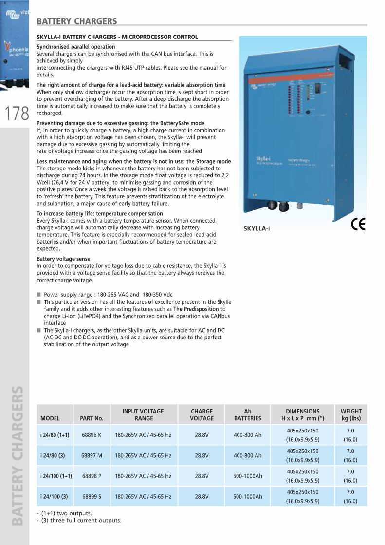
178
BATTERY CHARG
ERS
SKYLLA-I BATTERY CHARGERS - MICROPROCESSOR CONTROL
Synchronised parallel operationSeveral chargers can be synchronised with the CAN bus interface. This isachieved by simplyinterconnecting the chargers with RJ45 UTP cables. Please see the manual fordetails.
The right amount of charge for a lead-acid battery: variable absorption timeWhen only shallow discharges occur the absorption time is kept short in orderto prevent overcharging of the battery. After a deep discharge the absorptiontime is automatically increased to make sure that the battery is completelyrecharged.
Preventing damage due to excessive gassing: the BatterySafe modeIf, in order to quickly charge a battery, a high charge current in combinationwith a high absorption voltage has been chosen, the Skylla-i will preventdamage due to excessive gassing by automatically limiting therate of voltage increase once the gassing voltage has been reached
Less maintenance and aging when the battery is not in use: the Storage modeThe storage mode kicks in whenever the battery has not been subjected todischarge during 24 hours. In the storage mode float voltage is reduced to 2,2V/cell (26,4 V for 24 V battery) to minimise gassing and corrosion of thepositive plates. Once a week the voltage is raised back to the absorption levelto ‘refresh’ the battery. This feature prevents stratification of the electrolyteand sulphation, a major cause of early battery failure.
To increase battery life: temperature compensationEvery Skylla-i comes with a battery temperature sensor. When connected,charge voltage will automatically decrease with increasing batterytemperature. This feature is especially recommended for sealed lead-acidbatteries and/or when important fluctuations of battery temperature areexpected.
Battery voltage senseIn order to compensate for voltage loss due to cable resistance, the Skylla-i isprovided with a voltage sense facility so that the battery always receives thecorrect charge voltage.
� Power supply range : 180-265 VAC and 180-350 Vdc� This particular version has all the features of excellence present in the Skyllafamily and it adds other interesting features such as The Predisposition tocharge Li-Ion (LiFePO4) and the Synchronised parallel operation via CANbusinterface
� The Skylla-I chargers, as the other Skylla units, are suitable for AC and DC(AC-DC and DC-DC operation), and as a power source due to the perfectstabilization of the output voltage
SKYLLA-i
INPUT VOLTAGE CHARGE Ah DIMENSIONS WEIGHT MODEL PART No. RANGE VOLTAGE BATTERIES H x L x P mm (“) kg (lbs)
405x250x150 7.0
i 24/80 (1+1) 68896 K
180-265V AC / 45-65 Hz
28.8V 400-800 Ah
(16.0x9.9x5.9) (16.0)
405x250x150 7.0
i 24/80 (3) 68897 M
180-265V AC / 45-65 Hz
28.8V 400-800 Ah
(16.0x9.9x5.9) (16.0)
405x250x150 7.0
i 24/100 (1+1) 68898 P
180-265V AC / 45-65 Hz
28.8V 500-1000Ah
(16.0x9.9x5.9) (16.0)
405x250x150 7.0
i 24/100 (3) 68899 S
180-265V AC / 45-65 Hz
28.8V 500-1000Ah
(16.0x9.9x5.9) (16.0)
BATTERY CHARGERS
- (1+1) two outputs.- (3) three full current outputs.
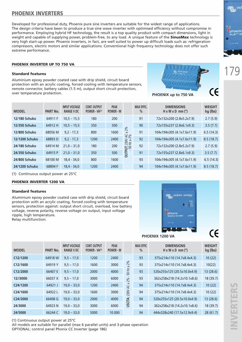
179
INVERTERS
INPUT VOLTAGE CONT. OUTPUT PEAK MAX EFFIC DIMENSIONS WEIGHT MODEL PART No. RANGE V DC POWER - VA(1) POWER - W % H x W x D mm (“) kg (lbs)
C12/1200 64918 W 9,5 – 17,0 1200 2400 93 375x214x110 (14.7x8.4x4.3) 10 (22)
C12/1600 64919 Y 9,5 – 17,0 1600 3000 93 375x214x110 (14.7x8.4x4.3) 10(22)
C12/2000 66407 E 9,5 – 17,0 2000 4000 93 520x255x125 (20.5x10.0x4.9) 13 (28.6)
12/3000 66037 X 9,5 – 17,0 3000 6000 93 362x258x218 (14.2x10.1x8.6) 18 (39.7)
C24/1200 64921 J 19,0 – 33,0 1200 2400 94 375x214x110 (14.7x8.4x4.3) 10 (22)
C24/1600 64922 L 19,0 – 33,0 1600 3000 94 375x214x110 (14.7x8.4x4.3) 10 (22)
C24/2000 66408 G 19,0 – 33,0 2000 4000 94 520x255x125 (20.5x10.0x4.9) 13 (28.6)
24/3000 64923 N 19,0 – 33,0 3000 6000 94 362x258x218 (14.2x10.1x8.6) 18 (39.7)
24/5000 66244 C 19,0 – 33,0 5000 10.000 94 444x328x240 (17.5x12.9x9.4) 28 (61.7)
PHOENIX INVERTERS
PHOENIX INVERTER UP TO 750 VA
Standard features
Aluminium epoxy powder coated case with drip shield, circuit boardprotection with an acrylic coating, forced cooling with temperature sensors,remote connector, battery cables (1.5 m), output short circuit protection,over temperature protection.
Developed for professional duty, Phoenix pure sine inverters are suitable for the widest range of applications. The design criteria have been to produce a true sine wave inverter with optimised efficiency without compromise inperformance. Employing hybrid HF technology, the result is a top quality product with compact dimensions, light inweight and capable of supplying power, problem-free, to any load. A unique feature of the SinusMax technology isvery high start-up power. Phoenix inverters, in fact, are well suited to power up difficult loads such as: refrigerationcompressors, electric motors and similar applications. Conventional high frequency technology does not offer suchextreme performance.
PHOENIX up to 750 VA
INPUT VOLTAGE CONT. OUTPUT PEAK MAX EFFIC. DIMENSIONS WEIGHT MODEL PART No. RANGE V DC POWER - VA(1) POWER - W % H x W x D mm (“) kg (lbs)
12/180 Schuko 64911 F 10,5 – 15,5 180 200 91 72x132x200 (2.8x5.2x7.9) 2.7 (5.9)
12/350 Schuko 64912 H 10,5 – 15,5 350 500 90 72x155x237 (2.8x6.1x9.3) 3.5 (7.7)
12/800 Schuko 68056 M 9,2 - 17,3 800 1600 91 104x194x305 (4.1x7.6x11.9) 6.5 (14.3)
12/1200 Schuko 68893 D 9,2 - 17,3 1200 2400 92 104x194x305 (4.1x7.6x11.9) 8.5 (18.7)
24/180 Schuko 64914 M 21,0 – 31,0 180 200 92 72x132x200 (2.8x5.2x7.9) 2.7 (5.9)
24/350 Schuko 64915 P 21,0 – 31,0 350 500 91 72x155x237 (2.8x6.1x9.3) 3.5 (7.7)
24/800 Schuko 68100 M 18,4 - 34,0 800 1600 93 104x194x305 (4.1x7.6x11.9) 6.5 (14.3)
24/1200 Schuko 68894 F 18,4 - 34,0 1200 2400 94 104x194x305 (4.1x7.6x11.9) 8.5 (18.7)
(1) Continuous output power at 25°C
OUTP
UT: 230V AC ± 2%
- 50 Hz ± 2%
USCITA
: 230V AC ± 2% - 50 Hz ± 2%
PHOENIX INVERTER 1200 VA
Standard features
Aluminium epoxy powder coated case with drip shield, circuit boardprotection with an acrylic coating, forced cooling with temperaturesensors, protection against: output short circuit, overload, low batteryvoltage, reverse polarity, reverse voltage on output, input voltageripple, high temperature. Relay multifunction.
PHOENIX 1200 VA
(1) Continuous output power at 25°CAll models are suitable for parallel (max 6 parallel units) and 3-phase operationOPTIONAL: control panel Phonix CC Inverter (page 186)
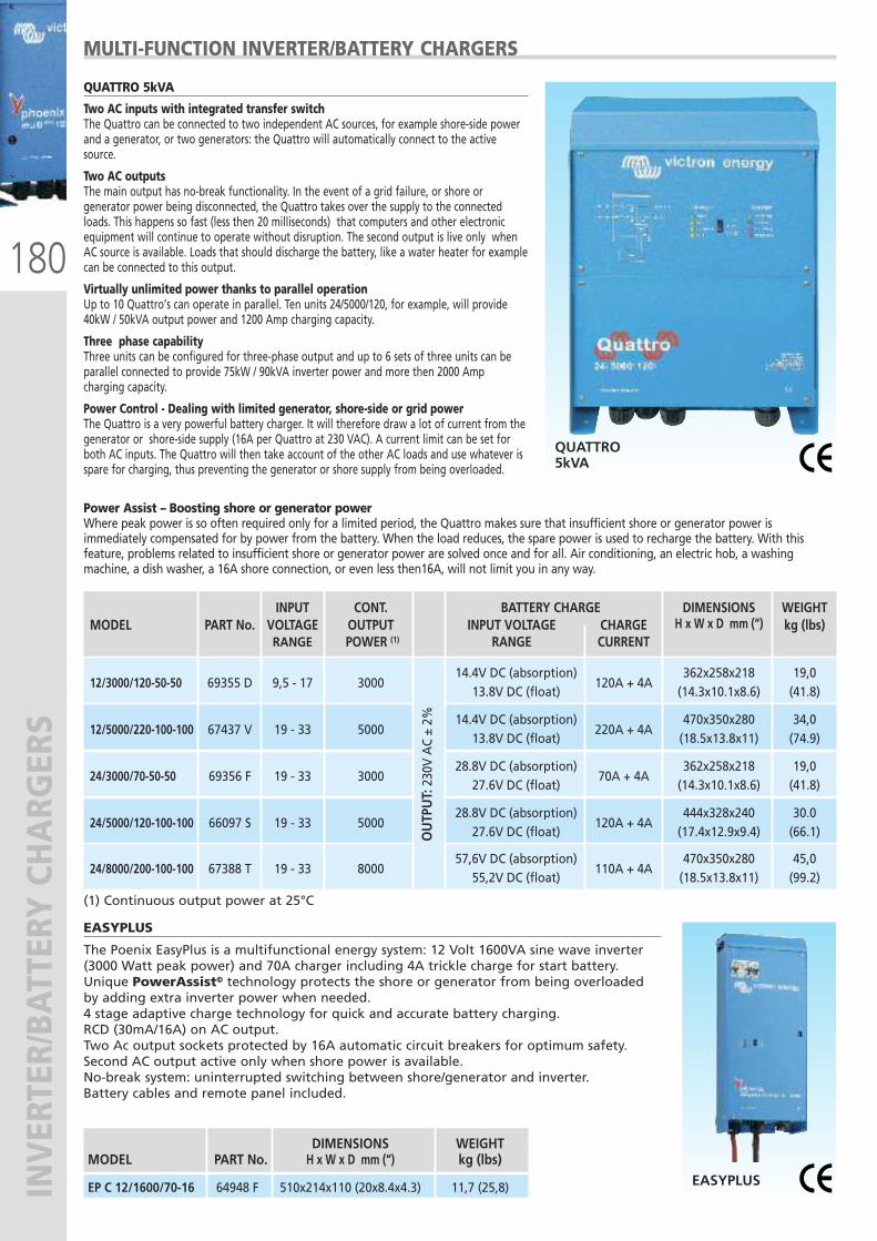
180
INVERTER/BATTERY CHARG
ERS
DIMENSIONS WEIGHT MODEL PART No. H x W x D mm (“) kg (lbs)
EP C 12/1600/70-16 64948 F 510x214x110 (20x8.4x4.3) 11,7 (25,8)
MULTI-FUNCTION INVERTER/BATTERY CHARGERS
Power Assist – Boosting shore or generator powerWhere peak power is so often required only for a limited period, the Quattro makes sure that insufficient shore or generator power isimmediately compensated for by power from the battery. When the load reduces, the spare power is used to recharge the battery. With thisfeature, problems related to insufficient shore or generator power are solved once and for all. Air conditioning, an electric hob, a washingmachine, a dish washer, a 16A shore connection, or even less then16A, will not limit you in any way.
QUATTRO 5kVA
Two AC inputs with integrated transfer switchThe Quattro can be connected to two independent AC sources, for example shore-side powerand a generator, or two generators: the Quattro will automatically connect to the activesource.
Two AC outputsThe main output has no-break functionality. In the event of a grid failure, or shore orgenerator power being disconnected, the Quattro takes over the supply to the connectedloads. This happens so fast (less then 20 milliseconds) that computers and other electronicequipment will continue to operate without disruption. The second output is live only whenAC source is available. Loads that should discharge the battery, like a water heater for examplecan be connected to this output.
Virtually unlimited power thanks to parallel operationUp to 10 Quattro’s can operate in parallel. Ten units 24/5000/120, for example, will provide40kW / 50kVA output power and 1200 Amp charging capacity.
Three phase capabilityThree units can be configured for three-phase output and up to 6 sets of three units can beparallel connected to provide 75kW / 90kVA inverter power and more then 2000 Ampcharging capacity.
Power Control - Dealing with limited generator, shore-side or grid powerThe Quattro is a very powerful battery charger. It will therefore draw a lot of current from thegenerator or shore-side supply (16A per Quattro at 230 VAC). A current limit can be set forboth AC inputs. The Quattro will then take account of the other AC loads and use whatever isspare for charging, thus preventing the generator or shore supply from being overloaded.
EASYPLUS
The Poenix EasyPlus is a multifunctional energy system: 12 Volt 1600VA sine wave inverter(3000 Watt peak power) and 70A charger including 4A trickle charge for start battery.Unique PowerAssist© technology protects the shore or generator from being overloadedby adding extra inverter power when needed.4 stage adaptive charge technology for quick and accurate battery charging. RCD (30mA/16A) on AC output.Two Ac output sockets protected by 16A automatic circuit breakers for optimum safety.Second AC output active only when shore power is available.No-break system: uninterrupted switching between shore/generator and inverter.Battery cables and remote panel included.
QUATTRO5kVA
EASYPLUS
INPUT CONT. BATTERY CHARGE DIMENSIONS WEIGHT MODEL PART No. VOLTAGE OUTPUT INPUT VOLTAGE CHARGE H x W x D mm (“) kg (lbs) RANGE POWER (1) RANGE CURRENT
14.4V DC (absorption) 362x258x218 19,0 12/3000/120-50-50 69355 D 9,5 - 17 3000 13.8V DC (float)
120A + 4A (14.3x10.1x8.6) (41.8)
14.4V DC (absorption) 470x350x280 34,0 12/5000/220-100-100 67437 V 19 - 33 5000
13.8V DC (float) 220A + 4A
(18.5x13.8x11) (74.9)
28.8V DC (absorption) 362x258x218 19,0 24/3000/70-50-50 69356 F 19 - 33 3000 27.6V DC (float)
70A + 4A (14.3x10.1x8.6) (41.8)
28.8V DC (absorption) 444x328x240 30.0 24/5000/120-100-100 66097 S 19 - 33 5000
27.6V DC (float) 120A + 4A
(17.4x12.9x9.4) (66.1)
57,6V DC (absorption) 470x350x280 45,0 24/8000/200-100-100 67388 T 19 - 33 8000
55,2V DC (float) 110A + 4A
(18.5x13.8x11) (99.2)
(1) Continuous output power at 25°C
OUTP
UT: 230V AC ± 2%
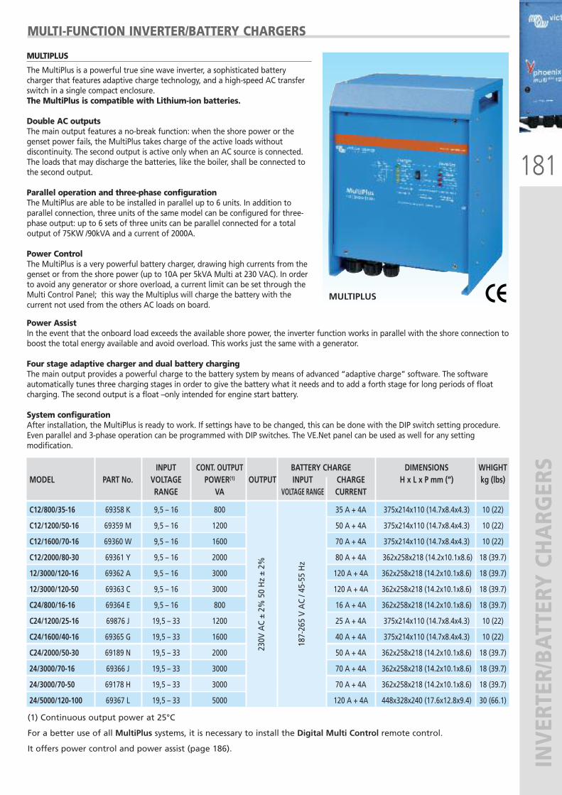
181
INVERTER/BATTERY CHARG
ERS
Power AssistIn the event that the onboard load exceeds the available shore power, the inverter function works in parallel with the shore connection toboost the total energy available and avoid overload. This works just the same with a generator.
Four stage adaptive charger and dual battery chargingThe main output provides a powerful charge to the battery system by means of advanced “adaptive charge” software. The softwareautomatically tunes three charging stages in order to give the battery what it needs and to add a forth stage for long periods of floatcharging. The second output is a float –only intended for engine start battery.
System configurationAfter installation, the MultiPlus is ready to work. If settings have to be changed, this can be done with the DIP switch setting procedure.Even parallel and 3-phase operation can be programmed with DIP switches. The VE.Net panel can be used as well for any settingmodification.
MULTIPLUS
The MultiPlus is a powerful true sine wave inverter, a sophisticated batterycharger that features adaptive charge technology, and a high-speed AC transferswitch in a single compact enclosure.The MultiPlus is compatible with Lithium-ion batteries.
Double AC outputsThe main output features a no-break function: when the shore power or thegenset power fails, the MultiPlus takes charge of the active loads withoutdiscontinuity. The second output is active only when an AC source is connected.The loads that may discharge the batteries, like the boiler, shall be connected tothe second output.
Parallel operation and three-phase configurationThe MultiPlus are able to be installed in parallel up to 6 units. In addition toparallel connection, three units of the same model can be configured for three-phase output: up to 6 sets of three units can be parallel connected for a totaloutput of 75KW /90kVA and a current of 2000A.
Power ControlThe MultiPlus is a very powerful battery charger, drawing high currents from thegenset or from the shore power (up to 10A per 5kVA Multi at 230 VAC). In orderto avoid any generator or shore overload, a current limit can be set through theMulti Control Panel; this way the Multiplus will charge the battery with thecurrent not used from the others AC loads on board.
MULTIPLUS
MULTI-FUNCTION INVERTER/BATTERY CHARGERS
(1) Continuous output power at 25°C
For a better use of all MultiPlus systems, it is necessary to install the Digital Multi Control remote control.
It offers power control and power assist (page 186).
INPUT CONT. OUTPUT BATTERY CHARGE DIMENSIONS WHIGHT MODEL PART No. VOLTAGE POWER(1) OUTPUT INPUT CHARGE H x L x P mm (“) kg (lbs) RANGE VA VOLTAGE RANGE CURRENT
C12/800/35-16 69358 K 9,5 – 16 800 35 A + 4A 375x214x110 (14.7x8.4x4.3) 10 (22)
C12/1200/50-16 69359 M 9,5 – 16 1200 50 A + 4A 375x214x110 (14.7x8.4x4.3) 10 (22)
C12/1600/70-16 69360 W 9,5 – 16 1600 70 A + 4A 375x214x110 (14.7x8.4x4.3) 10 (22)
C12/2000/80-30 69361 Y 9,5 – 16 2000 80 A + 4A 362x258x218 (14.2x10.1x8.6) 18 (39.7)
12/3000/120-16 69362 A 9,5 – 16 3000 120 A + 4A 362x258x218 (14.2x10.1x8.6) 18 (39.7)
12/3000/120-50 69363 C 9,5 – 16 3000 120 A + 4A 362x258x218 (14.2x10.1x8.6) 18 (39.7)
C24/800/16-16 69364 E 9,5 – 16 800 16 A + 4A 362x258x218 (14.2x10.1x8.6) 18 (39.7)
C24/1200/25-16 69876 J 19,5 – 33 1200 25 A + 4A 375x214x110 (14.7x8.4x4.3) 10 (22)
C24/1600/40-16 69365 G 19,5 – 33 1600 40 A + 4A 375x214x110 (14.7x8.4x4.3) 10 (22)
C24/2000/50-30 69189 N 19,5 – 33 2000 50 A + 4A 362x258x218 (14.2x10.1x8.6) 18 (39.7)
24/3000/70-16 69366 J 19,5 – 33 3000 70 A + 4A 362x258x218 (14.2x10.1x8.6) 18 (39.7)
24/3000/70-50 69178 H 19,5 – 33 3000 70 A + 4A 362x258x218 (14.2x10.1x8.6) 18 (39.7)
24/5000/120-100 69367 L 19,5 – 33 5000 120 A + 4A 448x328x240 (17.6x12.8x9.4) 30 (66.1)
230V AC ± 2%
50 Hz ± 2%
187-265 V AC / 45-55 Hz
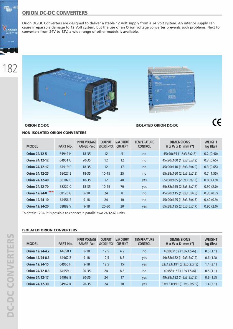
182
DC-DC CO
NVERTERS
ORION DC-DC CONVERTERS
Orion DC/DC Converters are designed to deliver a stable 12 Volt supply from a 24 Volt system. An inferior supply cancause irreparable damage to 12 Volt system, but the use of an Orion voltage converter prevents such problems. Next toconverters from 24V to 12V, a wide range of other models is available.
ORION DC-DC ISOLATED ORION DC-DC
NON ISOLATED ORION CONVERTERS
INPUT VOLTAGE OUTPUT MAX OUTPUT TEMPERATURE DIMENSIONS WEIGHT MODEL PART No. RANGE - Vcc VOLTAGE - VDC CURRENT CONTROL H x W x D mm (“) kg (lbs)
Orion 24/12-5 64949 H 18-35 12 5 no 45x90x65 (1.8x3.5x2.6) 0.2 (0.40)
Orion 24/12-12 64951 U 20-35 12 12 no 45x90x100 (1.8x3.5x3.9) 0.3 (0.65)
Orion 24/12-17 67919 P 18-35 12 17 no 45x90x110 (1.8x3.5x4.0) 0.3 (0.65)
Orion 24/12-25 68027 E 18-35 10-15 25 no 65x88x160 (2.6x3.5x7.3) 0.7 (1.55)
Orion 24/12-40 68107 C 18-35 12 40 yes 65x88x185 (2.6x3.5x7.3) 0.85 (1.9)
Orion 24/12-70 68222 C 18-35 10-15 70 yes 65x88x195 (2.6x3.5x7.7) 0.90 (2.0)
Orion 12/24-8 68126 G 9-18 24 8 no 45x90x115 (1.8x3.5x4.5) 0.30 (0.7)
Orion 12/24-10 64956 E 9-18 24 10 no 45x90x125 (1.8x3.5x4.5) 0.40 (0.9)
Orion 12/24-20 68882 Y 9-18 20-30 20 yes 65x88x195 (2.6x3.5x7.7) 0.90 (2.0)
To obtain 120A, it is possible to connect in parallel two 24/12-60 units.
ISOLATED ORION CONVERTERS
INPUT VOLTAGE OUTPUT MAX OUTPUT TEMPERATURE DIMENSIONS WEIGHT MODEL PART No. RANGE - Vcc VOLTAGE - VDC CURRENT CONTROL H x W x D mm (“) kg (lbs)
Orion 12/24-4,2 64958 J 9-18 12,5 4,2 no 49x88x152 (1.9x3.5x6) 0.5 (1.1)
Orion 12/24-8,3 64962 Z 9-18 12,5 8,3 yes 49x88x182 (1.9x3.5x7.2) 0.6 (1.3)
Orion 12/24-15 64966 H 9-18 12,5 15 yes 83x133x191 (3.3x5.2x7.5) 1.4 (3.1)
Orion 24/12-8,3 64959 L 20-35 24 8,3 no 49x88x152 (1.9x3.5x6) 0.5 (1.1)
Orion 24/12-17 64963 B 20-35 24 17 yes 49x88x182 (1.9x3.5x7.2) 0.6 (1.3)
Orion 24/12-30 64967 K 20-35 24 30 yes 83x133x191 (3.3x5.2x7.5) 1.4 (3.1)
new new
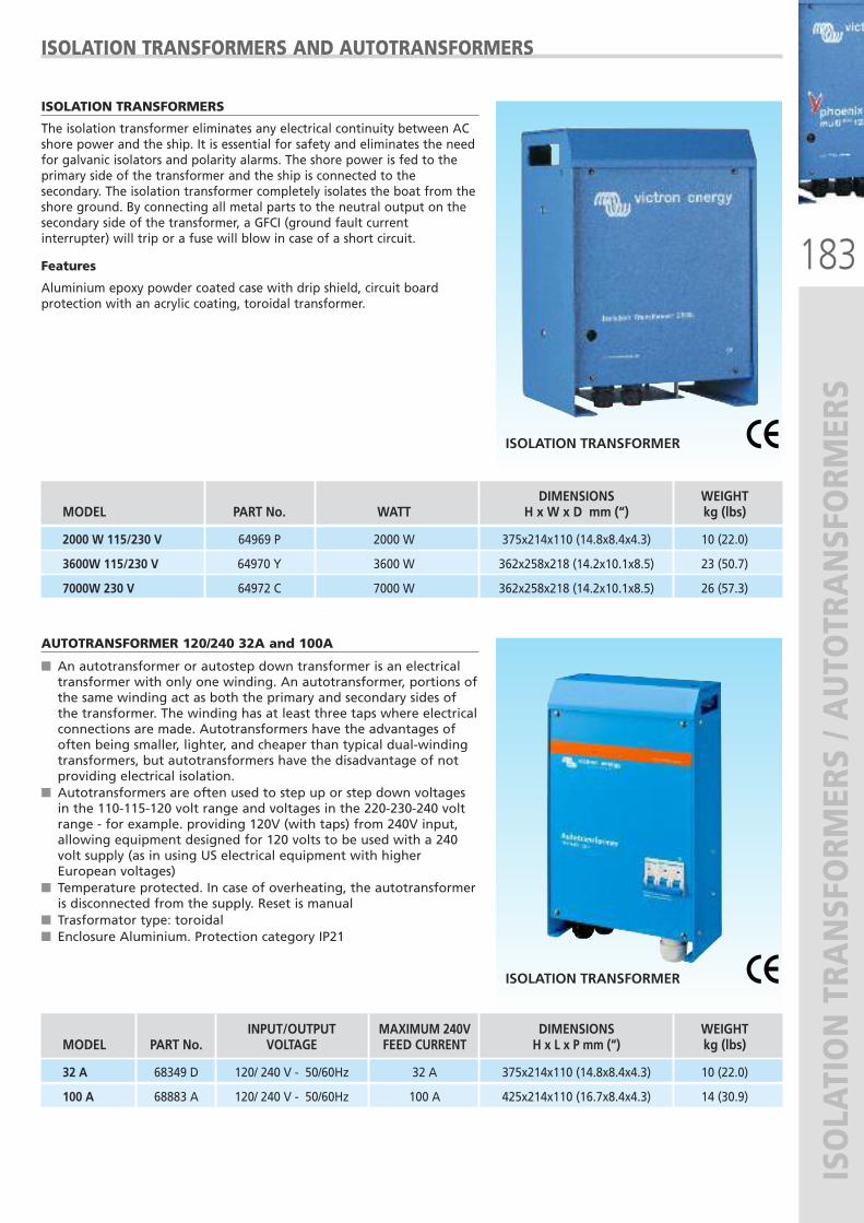
183
ISOLATION TRA
NSFORM
ERS / AUTOTRANSFORM
ERS
ISOLATION TRANSFORMERS
The isolation transformer eliminates any electrical continuity between ACshore power and the ship. It is essential for safety and eliminates the needfor galvanic isolators and polarity alarms. The shore power is fed to theprimary side of the transformer and the ship is connected to thesecondary. The isolation transformer completely isolates the boat from theshore ground. By connecting all metal parts to the neutral output on thesecondary side of the transformer, a GFCI (ground fault currentinterrupter) will trip or a fuse will blow in case of a short circuit.
Features
Aluminium epoxy powder coated case with drip shield, circuit boardprotection with an acrylic coating, toroidal transformer.
ISOLATION TRANSFORMER
DIMENSIONS WEIGHT MODEL PART No. WATT H x W x D mm (“) kg (lbs)
2000 W 115/230 V 64969 P 2000 W 375x214x110 (14.8x8.4x4.3) 10 (22.0)
3600W 115/230 V 64970 Y 3600 W 362x258x218 (14.2x10.1x8.5) 23 (50.7)
7000W 230 V 64972 C 7000 W 362x258x218 (14.2x10.1x8.5) 26 (57.3)
ISOLATION TRANSFORMERS AND AUTOTRANSFORMERS
AUTOTRANSFORMER 120/240 32A and 100A
� An autotransformer or autostep down transformer is an electricaltransformer with only one winding. An autotransformer, portions ofthe same winding act as both the primary and secondary sides ofthe transformer. The winding has at least three taps where electricalconnections are made. Autotransformers have the advantages ofoften being smaller, lighter, and cheaper than typical dual-windingtransformers, but autotransformers have the disadvantage of notproviding electrical isolation.
� Autotransformers are often used to step up or step down voltagesin the 110-115-120 volt range and voltages in the 220-230-240 voltrange - for example. providing 120V (with taps) from 240V input,allowing equipment designed for 120 volts to be used with a 240volt supply (as in using US electrical equipment with higherEuropean voltages)
� Temperature protected. In case of overheating, the autotransformeris disconnected from the supply. Reset is manual
� Trasformator type: toroidal� Enclosure Aluminium. Protection category IP21
ISOLATION TRANSFORMER
INPUT/OUTPUT MAXIMUM 240V DIMENSIONS WEIGHT MODEL PART No. VOLTAGE FEED CURRENT H x L x P mm (“) kg (lbs)
32 A 68349 D 120/ 240 V - 50/60Hz 32 A 375x214x110 (14.8x8.4x4.3) 10 (22.0)
100 A 68883 A 120/ 240 V - 50/60Hz 100 A 425x214x110 (16.7x8.4x4.3) 14 (30.9)
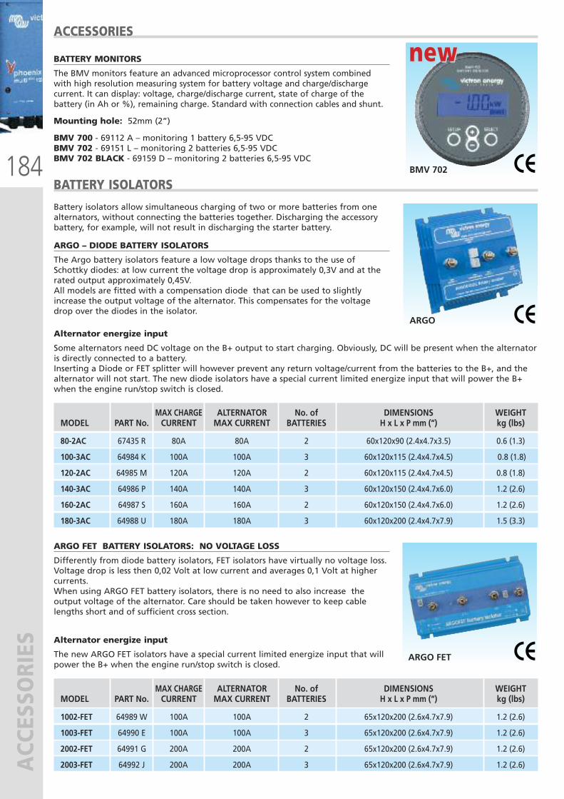
184
ACCESSORIES
ACCESSORIES
BATTERY MONITORS
The BMV monitors feature an advanced microprocessor control system combinedwith high resolution measuring system for battery voltage and charge/dischargecurrent. It can display: voltage, charge/discharge current, state of charge of thebattery (in Ah or %), remaining charge. Standard with connection cables and shunt.
Mounting hole: 52mm (2”)
BMV 700 - 69112 A – monitoring 1 battery 6,5-95 VDCBMV 702 - 69151 L – monitoring 2 batteries 6,5-95 VDCBMV 702 BLACK - 69159 D – monitoring 2 batteries 6,5-95 VDC
BMV 702
new new
Battery isolators allow simultaneous charging of two or more batteries from onealternators, without connecting the batteries together. Discharging the accessorybattery, for example, will not result in discharging the starter battery.
ARGO – DIODE BATTERY ISOLATORS
The Argo battery isolators feature a low voltage drops thanks to the use ofSchottky diodes: at low current the voltage drop is approximately 0,3V and at therated output approximately 0,45V. All models are fitted with a compensation diode that can be used to slightlyincrease the output voltage of the alternator. This compensates for the voltagedrop over the diodes in the isolator.
BATTERY ISOLATORS
Alternator energize input
Some alternators need DC voltage on the B+ output to start charging. Obviously, DC will be present when the alternatoris directly connected to a battery. Inserting a Diode or FET splitter will however prevent any return voltage/current from the batteries to the B+, and thealternator will not start. The new diode isolators have a special current limited energize input that will power the B+when the engine run/stop switch is closed.
ARGO FET BATTERY ISOLATORS: NO VOLTAGE LOSS
Differently from diode battery isolators, FET isolators have virtually no voltage loss.Voltage drop is less then 0,02 Volt at low current and averages 0,1 Volt at highercurrents.When using ARGO FET battery isolators, there is no need to also increase theoutput voltage of the alternator. Care should be taken however to keep cablelengths short and of sufficient cross section.
Alternator energize input
The new ARGO FET isolators have a special current limited energize input that willpower the B+ when the engine run/stop switch is closed.
ARGO FET
MAX CHARGE ALTERNATOR No. of DIMENSIONS WEIGHTMODEL PART No. CURRENT MAX CURRENT BATTERIES H x L x P mm (“) kg (lbs)
80-2AC 67435 R 80A 80A 2 60x120x90 (2.4x4.7x3.5) 0.6 (1.3)
100-3AC 64984 K 100A 100A 3 60x120x115 (2.4x4.7x4.5) 0.8 (1.8)
120-2AC 64985 M 120A 120A 2 60x120x115 (2.4x4.7x4.5) 0.8 (1.8)
140-3AC 64986 P 140A 140A 3 60x120x150 (2.4x4.7x6.0) 1.2 (2.6)
160-2AC 64987 S 160A 160A 2 60x120x150 (2.4x4.7x6.0) 1.2 (2.6)
180-3AC 64988 U 180A 180A 3 60x120x200 (2.4x4.7x7.9) 1.5 (3.3)
MAX CHARGE ALTERNATOR No. of DIMENSIONS WEIGHTMODEL PART No. CURRENT MAX CURRENT BATTERIES H x L x P mm (“) kg (lbs)
1002-FET 64989 W 100A 100A 2 65x120x200 (2.6x4.7x7.9) 1.2 (2.6)
1003-FET 64990 E 100A 100A 3 65x120x200 (2.6x4.7x7.9) 1.2 (2.6)
2002-FET 64991 G 200A 200A 2 65x120x200 (2.6x4.7x7.9) 1.2 (2.6)
2003-FET 64992 J 200A 200A 3 65x120x200 (2.6x4.7x7.9) 1.2 (2.6)
ARGO
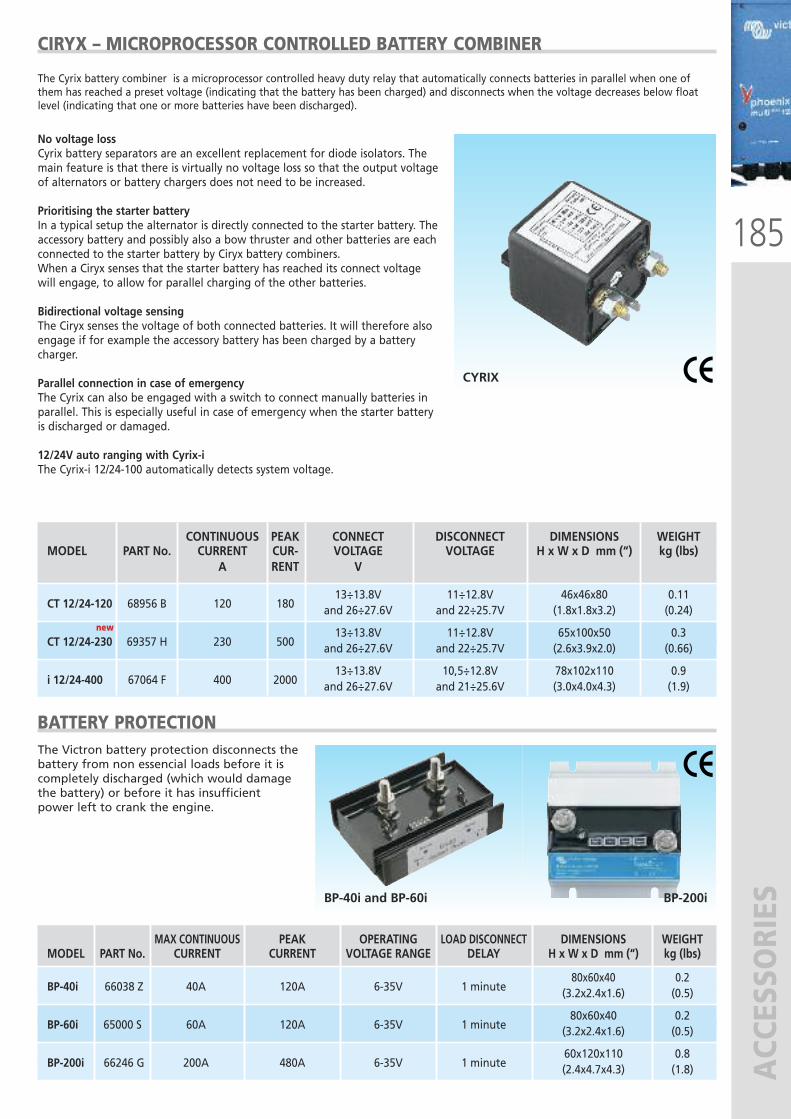
185
ACCESSORIESBP-40i and BP-60i BP-200i
CONTINUOUS PEAK CONNECT DISCONNECT DIMENSIONS WEIGHT MODEL PART No. CURRENT CUR- VOLTAGE VOLTAGE H x W x D mm (“) kg (lbs)
A RENT V
13÷13.8V 11÷12.8V 46x46x80 0.11 CT 12/24-120 68956 B 120 180 and 26÷27.6V and 22÷25.7V (1.8x1.8x3.2) (0.24)
13÷13.8V 11÷12.8V 65x100x50 0.3 CT 12/24-230 69357 H 230 500 and 26÷27.6V and 22÷25.7V (2.6x3.9x2.0) (0.66)
13÷13.8V 10,5÷12.8V 78x102x110 0.9 i 12/24-400 67064 F 400 2000 and 26÷27.6V and 21÷25.6V (3.0x4.0x4.3) (1.9)
CIRYX – MICROPROCESSOR CONTROLLED BATTERY COMBINER
BATTERY PROTECTION
No voltage lossCyrix battery separators are an excellent replacement for diode isolators. Themain feature is that there is virtually no voltage loss so that the output voltageof alternators or battery chargers does not need to be increased.
Prioritising the starter batteryIn a typical setup the alternator is directly connected to the starter battery. Theaccessory battery and possibly also a bow thruster and other batteries are eachconnected to the starter battery by Ciryx battery combiners.When a Ciryx senses that the starter battery has reached its connect voltagewill engage, to allow for parallel charging of the other batteries.
Bidirectional voltage sensingThe Ciryx senses the voltage of both connected batteries. It will therefore alsoengage if for example the accessory battery has been charged by a batterycharger.
Parallel connection in case of emergencyThe Cyrix can also be engaged with a switch to connect manually batteries inparallel. This is especially useful in case of emergency when the starter batteryis discharged or damaged.
12/24V auto ranging with Cyrix-iThe Cyrix-i 12/24-100 automatically detects system voltage.
The Cyrix battery combiner is a microprocessor controlled heavy duty relay that automatically connects batteries in parallel when one ofthem has reached a preset voltage (indicating that the battery has been charged) and disconnects when the voltage decreases below floatlevel (indicating that one or more batteries have been discharged).
The Victron battery protection disconnects thebattery from non essencial loads before it iscompletely discharged (which would damagethe battery) or before it has insufficientpower left to crank the engine.
MAX CONTINUOUS PEAK OPERATING LOAD DISCONNECT DIMENSIONS WEIGHT MODEL PART No. CURRENT CURRENT VOLTAGE RANGE DELAY H x W x D mm (“) kg (lbs)
80x60x40 0.2 BP-40i 66038 Z 40A 120A 6-35V 1 minute (3.2x2.4x1.6) (0.5)
80x60x40 0.2 BP-60i 65000 S 60A 120A 6-35V 1 minute (3.2x2.4x1.6) (0.5)
60x120x110 0.8 BP-200i 66246 G 200A 480A 6-35V 1 minute (2.4x4.7x4.3) (1.8)
CYRIX
new new
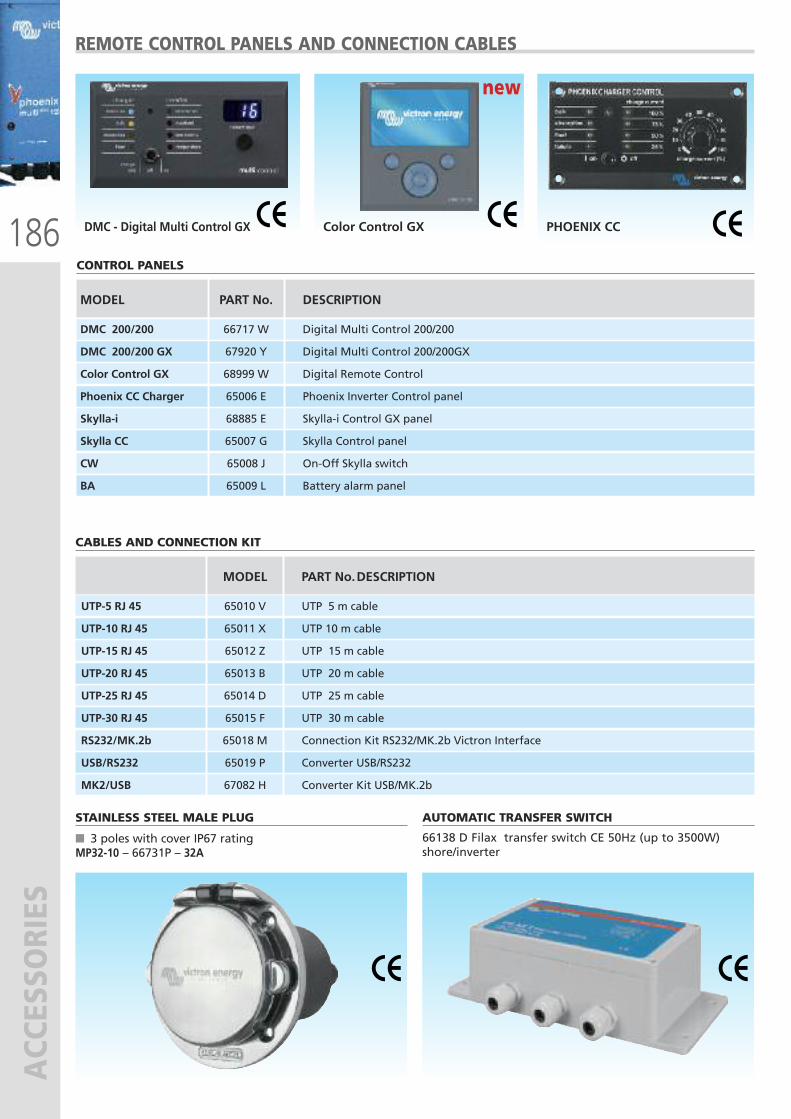
MODEL PART No.DESCRIPTION
UTP-5 RJ 45 65010 V UTP 5 m cable
UTP-10 RJ 45 65011 X UTP 10 m cable
UTP-15 RJ 45 65012 Z UTP 15 m cable
UTP-20 RJ 45 65013 B UTP 20 m cable
UTP-25 RJ 45 65014 D UTP 25 m cable
UTP-30 RJ 45 65015 F UTP 30 m cable
RS232/MK.2b 65018 M Connection Kit RS232/MK.2b Victron Interface
USB/RS232 65019 P Converter USB/RS232
MK2/USB 67082 H Converter Kit USB/MK.2b
186
ACCESSORIES
REMOTE CONTROL PANELS AND CONNECTION CABLES
PHOENIX CCColor Control GXDMC - Digital Multi Control GX
MODEL PART No. DESCRIPTION
DMC 200/200 66717 W Digital Multi Control 200/200
DMC 200/200 GX 67920 Y Digital Multi Control 200/200GX
Color Control GX 68999 W Digital Remote Control
Phoenix CC Charger 65006 E Phoenix Inverter Control panel
Skylla-i 68885 E Skylla-i Control GX panel
Skylla CC 65007 G Skylla Control panel
CW 65008 J On-Off Skylla switch
BA 65009 L Battery alarm panel
CONTROL PANELS
CABLES AND CONNECTION KIT
STAINLESS STEEL MALE PLUG
� 3 poles with cover IP67 ratingMP32-10 – 66731P – 32A
AUTOMATIC TRANSFER SWITCH
66138 D Filax transfer switch CE 50Hz (up to 3500W)shore/inverter
new new
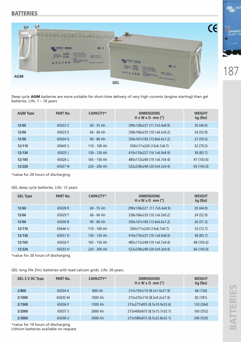
187
BATTERIES
BATTERIES
AGM
GEL
Deep cycle AGM batteries are more suitable for short-time delivery of very high currents (engine starting) than gelbatteries. Life: 7 – 10 years
*value for 20 hours of discharging
GEL deep cycle batteries. Life: 12 years
AGM Type PART No. CAPACITY* DIMENSIONS WEIGHT H x W x D mm (“) kg (lbs)
12/60 65022 C 60 - 55 Ah 299x138x227 (11.7x5.4x8.9) 20 (44.0)
12/66 65023 E 66 - 60 Ah 258x166x235 (10.1x6.5x9.2) 24 (52.9)
12/90 65024 G 90 - 80 Ah 350x167x183 (13.8x6.6x7.2) 27 (59.5)
12/110 65645 S 110 - 100 Ah 330x171x220 (13x6.7x8.7) 32 (70.5)
12/130 65025 J 130 - 120 Ah 410x176x227 (16.1x6.9x8.9) 38 (83.7)
12/165 65026 L 165 - 150 Ah 485x172x240 (19.1x6.7x9.4) 47 (103.6)
12/220 65027 N 220 - 200 Ah 522x238x240 (20.5x9.3x9.4) 65 (143.0)
GEL Type PART No. CAPACITY* DIMENSIONS WEIGHT H x W x D mm (“) kg (lbs)
12/60 65028 R 60 - 55 Ah 299x138x227 (11.7x5.4x8.9) 20 (44.0)
12/66 65029 T 66 - 60 Ah 258x166x235 (10.1x6.5x9.2) 24 (52.9)
12/90 65030 B 90 - 80 Ah 350x167x183 (13.8x6.6x7.2) 26 (57.3)
12/110 65646 U 110 - 100 Ah 330x171x220 (13x6.7x8.7) 33 (72.7)
12/130 65031 D 130 - 120 Ah 410x176x227 (16.1x6.9x8.9) 38 (83.7)
12/165 65032 F 165 - 150 Ah 485x172x240 (19.1x6.7x9.4) 48 (103.6)
12/220 65033 H 220 - 200 Ah 522x238x240 (20.5x9.3x9.4) 66 (143.0)
GEL 2 V DC Type PART No. CAPACITY* DIMENSIONS WEIGHT H x W x D mm (“) kg (lbs)
2/800 65034 K 800 Ah 215x193x710 (8.5x7.6x27.9) 68 (150)
2/1000 65035 M 1000 Ah 215x235x710 (8.5x9.2x27.9) 82 (181)
2/1500 65036 P 1500 Ah 215x277x855 (8.5x10.9x33.6) 120 (264)
2/2000 65037 S 2000 Ah 215x400x815 (8.5x15.7x32.1) 160 (352)
2/3000 65038 U 3000 Ah 215x580x815 (8.5x22.8x32.1) 240 (529)
*value for 20 hours of discharging
GEL long life 2Vcc batteries with lead calcium grids. Life: 20 years.
*value for 10 hours of discharging Lithium batteries available on request
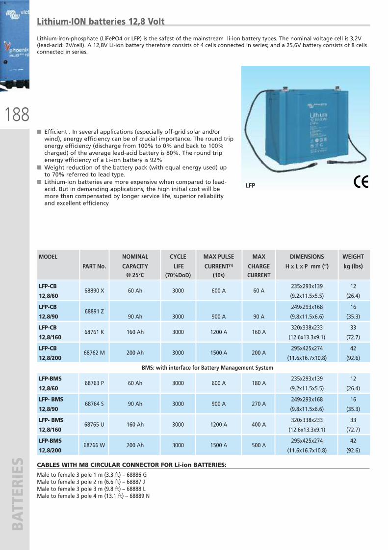
188
BATTERIES
Lithium-ION batteries 12,8 Volt
Lithium-iron-phosphate (LiFePO4 or LFP) is the safest of the mainstream li-ion battery types. The nominal voltage cell is 3,2V(lead-acid: 2V/cell). A 12,8V Li-ion battery therefore consists of 4 cells connected in series; and a 25,6V battery consists of 8 cellsconnected in series.
LFP
� Efficient . In several applications (especially off-grid solar and/orwind), energy efficiency can be of crucial importance. The round tripenergy efficiency (discharge from 100% to 0% and back to 100%charged) of the average lead-acid battery is 80%. The round tripenergy efficiency of a Li-ion battery is 92%
� Weight reduction of the battery pack (with equal energy used) upto 70% referred to lead type.
� Lithium-ion batteries are more expensive when compared to lead-acid. But in demanding applications, the high initial cost will bemore than compensated by longer service life, superior reliabilityand excellent efficiency
MODEL NOMINAL CYCLE MAX PULSE MAX DIMENSIONS WEIGHT
PART No. CAPACITY LIFE CURRENT(1) CHARGE H x L x P mm (“) kg (lbs) @ 25°C (70%DoD) (10s) CURRENT
LFP-CB 235x293x139 12
12,8/60 68890 X 60 Ah 3000 600 A 60 A
(9.2x11.5x5.5) (26.4)
LFP-CB 249x293x168 16
12,8/90 68891 Z
90 Ah 3000 900 A 90 A (9.8x11.5x6.6) (35.3)
LFP-CB 320x338x233 33
12,8/160 68761 K
160 Ah 3000 1200 A 160 A
(12.6x13.3x9.1) (72.7)
LFP-CB 295x425x274 42
12,8/200 68762 M
200 Ah 3000 1500 A 200 A
(11.6x16.7x10.8) (92.6)
BMS: with interface for Battery Management System
LFP-BMS 235x293x139 12
12,8/60 68763 P 60 Ah 3000 600 A 180 A
(9.2x11.5x5.5) (26.4)
LFP- BMS 249x293x168 16
12,8/90 68764 S 90 Ah 3000 900 A 270 A
(9.8x11.5x6.6) (35.3)
LFP- BMS 320x338x233 33
12,8/160 68765 U 160 Ah 3000 1200 A 400 A
(12.6x13.3x9.1) (72.7)
LFP-BMS 295x425x274 42
12,8/200 68766 W 200 Ah 3000 1500 A 500 A
(11.6x16.7x10.8) (92.6)
CABLES WITH M8 CIRCULAR CONNECTOR FOR Li-ion BATTERIES:
Male to female 3 pole 1 m (3.3 ft) – 68886 GMale to female 3 pole 2 m (6.6 ft) – 68887 JMale to female 3 pole 3 m (9.8 ft) – 68888 LMale to female 3 pole 4 m (13.1 ft) – 68889 N
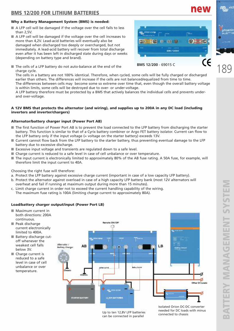
Why a Battery Management System (BMS) is needed:
� A LFP cell will be damaged if the voltage over the cell falls to lessthan 2,5V.
� A LFP cell will be damaged if the voltage over the cell increases tomore than 4,2V. Lead-acid batteries will eventually also bedamaged when discharged too deeply or overcharged, but notimmediately. A lead-acid battery will recover from total dischargeeven after it has been left in discharged state during days or weeks(depending on battery type and brand).
� The cells of a LFP battery do not auto-balance at the end of thecharge cycle. The cells in a battery are not 100% identical. Therefore, when cycled, some cells will be fully charged or dischargedearlier than others. The differences will increase if the cells are not balanced/equalized from time to time. The differences between cells may become some so extreme over time that, even though the overall battery voltageis within limits, some cells will be destroyed due to over- or under-voltage. A LFP battery therefore must be protected by a BMS that actively balances the individual cells and prevents under-and over-voltage.
A 12V BMS that protects the alternator (and wiring), and supplies up to 200A in any DC load (includinginverters and inverter/chargers)
Alternator/battery charger input (Power Port AB)
� The first function of Power Port AB is to prevent the load connected to the LFP battery from discharging the starterbattery. This function is similar to that of a Cyrix battery combiner or Argo FET battery isolator. Current can flow tothe LFP battery only if the input voltage (= voltage on the starter battery) exceeds 13V.
� Current cannot flow back from the LFP battery to the starter battery, thus preventing eventual damage to the LFPbattery due to excessive discharge.
� Excessive input voltage and transients are regulated down to a safe level. � Charge current is reduced to a safe level in case of cell unbalance or over temperature. � The input current is electronically limited to approximately 80% of the AB fuse rating. A 50A fuse, for example, willtherefore limit the input current to 40A.
Choosing the right fuse will therefore: a. Protect the LFP battery against excessive charge current (important in case of a low capacity LFP battery). b. Protect the alternator against overload in case of a high capacity LFP battery bank (most 12V alternators willoverheat and fail if running at maximum output during more than 15 minutes).
c. Limit charge current in order not to exceed the current handling capability of the wiring. The maximum fuse rating is 100A (limiting charge current to approximately 80A).
Load/battery charger output/input (Power Port LB)
� Maximum current inboth directions: 200Acontinuous.
� Peak dischargecurrent electronicallylimited to 400A.
� Battery discharge cut-off whenever theweakest cell fallsbelow 3V.
� Charge current isreduced to a safelevel in case of cellunbalance or overtemperature.
189
BATTERY MANAGEM
ENT SYSTEM
BMS 12/200 FOR LITHIUM BATTERIES
BMS 12/200 - 69015 C
new new
Up to ten 12,8V LFP batteriescan be connected in parallel
Isolated Orion DC-DC converterneeded for DC loads with minusconnected to chassis
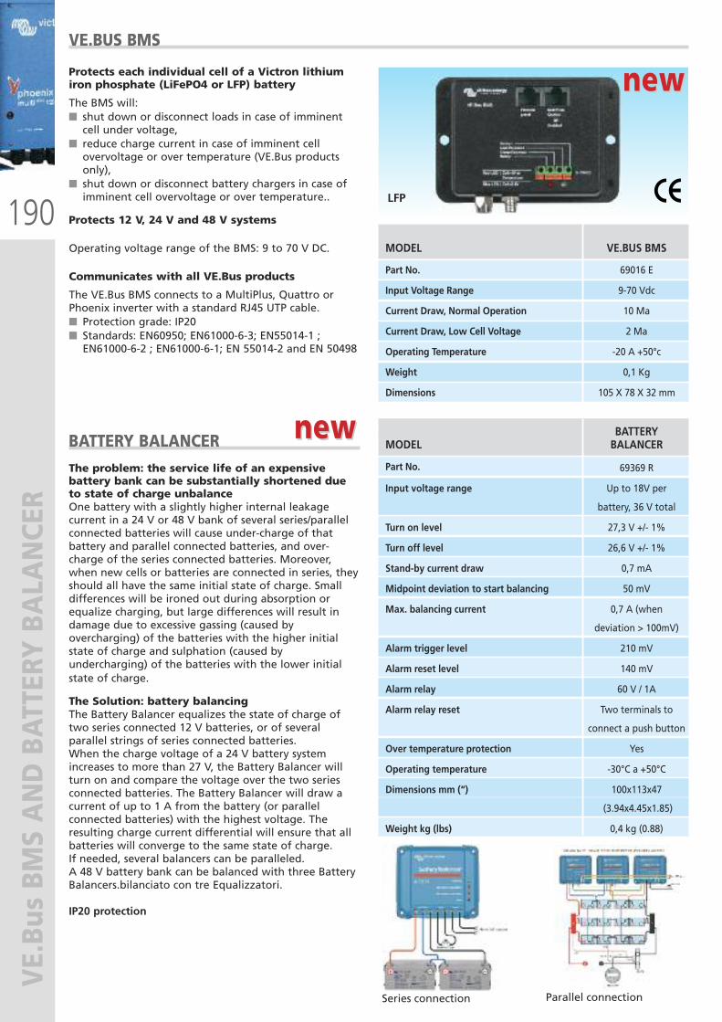
190
VE.Bus BM
S AND BATTERY BALANCER
VE.BUS BMS
BATTERY BALANCER
LFP
Protects each individual cell of a Victron lithiumiron phosphate (LiFePO4 or LFP) battery
The BMS will:� shut down or disconnect loads in case of imminentcell under voltage,
� reduce charge current in case of imminent cellovervoltage or over temperature (VE.Bus productsonly),
� shut down or disconnect battery chargers in case ofimminent cell overvoltage or over temperature..
Protects 12 V, 24 V and 48 V systems
Operating voltage range of the BMS: 9 to 70 V DC.
Communicates with all VE.Bus products
The VE.Bus BMS connects to a MultiPlus, Quattro orPhoenix inverter with a standard RJ45 UTP cable. � Protection grade: IP20� Standards: EN60950; EN61000-6-3; EN55014-1 ;EN61000-6-2 ; EN61000-6-1; EN 55014-2 and EN 50498
The problem: the service life of an expensivebattery bank can be substantially shortened dueto state of charge unbalanceOne battery with a slightly higher internal leakagecurrent in a 24 V or 48 V bank of several series/parallelconnected batteries will cause under-charge of thatbattery and parallel connected batteries, and over-charge of the series connected batteries. Moreover,when new cells or batteries are connected in series, theyshould all have the same initial state of charge. Smalldifferences will be ironed out during absorption orequalize charging, but large differences will result indamage due to excessive gassing (caused byovercharging) of the batteries with the higher initialstate of charge and sulphation (caused byundercharging) of the batteries with the lower initialstate of charge.
The Solution: battery balancing The Battery Balancer equalizes the state of charge oftwo series connected 12 V batteries, or of severalparallel strings of series connected batteries.When the charge voltage of a 24 V battery systemincreases to more than 27 V, the Battery Balancer willturn on and compare the voltage over the two seriesconnected batteries. The Battery Balancer will draw acurrent of up to 1 A from the battery (or parallelconnected batteries) with the highest voltage. Theresulting charge current differential will ensure that allbatteries will converge to the same state of charge.If needed, several balancers can be paralleled.A 48 V battery bank can be balanced with three BatteryBalancers.bilanciato con tre Equalizzatori.
IP20 protection
MODEL VE.BUS BMS
Part No. 69016 E
Input Voltage Range 9-70 Vdc
Current Draw, Normal Operation 10 Ma
Current Draw, Low Cell Voltage 2 Ma
Operating Temperature -20 A +50°c
Weight 0,1 Kg
Dimensions 105 X 78 X 32 mm
BATTERY
MODEL BALANCER
Part No. 69369 R
Input voltage range Up to 18V per
battery, 36 V total
Turn on level 27,3 V +/- 1%
Turn off level 26,6 V +/- 1%
Stand-by current draw 0,7 mA
Midpoint deviation to start balancing 50 mV
Max. balancing current 0,7 A (when
deviation > 100mV)
Alarm trigger level 210 mV
Alarm reset level 140 mV
Alarm relay 60 V / 1A
Alarm relay reset Two terminals to
connect a push button
Over temperature protection Yes
Operating temperature -30°C a +50°C
Dimensions mm (“) 100x113x47
(3.94x4.45x1.85)
Weight kg (lbs) 0,4 kg (0.88)
Series connection Parallel connection
new new
new new
191
WIND & SOLAR
WIND & SOLARRENEWABLE ENERGY
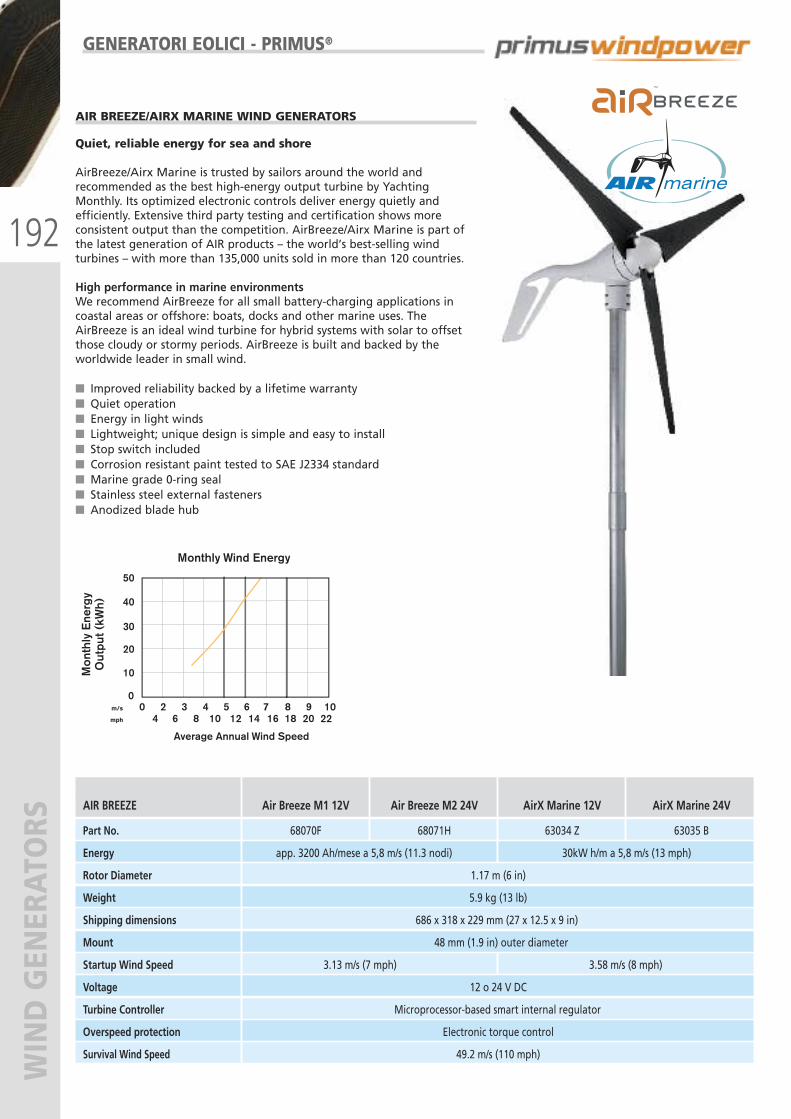
192
WIND GENERATORS
AIR BREEZE/AIRX MARINE WIND GENERATORS
Quiet, reliable energy for sea and shore
AirBreeze/Airx Marine is trusted by sailors around the world andrecommended as the best high-energy output turbine by YachtingMonthly. Its optimized electronic controls deliver energy quietly andefficiently. Extensive third party testing and certification shows moreconsistent output than the competition. AirBreeze/Airx Marine is part ofthe latest generation of AIR products – the world’s best-selling windturbines – with more than 135,000 units sold in more than 120 countries.
High performance in marine environmentsWe recommend AirBreeze for all small battery-charging applications incoastal areas or offshore: boats, docks and other marine uses. TheAirBreeze is an ideal wind turbine for hybrid systems with solar to offsetthose cloudy or stormy periods. AirBreeze is built and backed by theworldwide leader in small wind.
� Improved reliability backed by a lifetime warranty� Quiet operation� Energy in light winds� Lightweight; unique design is simple and easy to install� Stop switch included� Corrosion resistant paint tested to SAE J2334 standard� Marine grade 0-ring seal� Stainless steel external fasteners� Anodized blade hub
AIR BREEZE Air Breeze M1 12V Air Breeze M2 24V AirX Marine 12V AirX Marine 24V
Part No. 68070F 68071H 63034 Z 63035 B
Energy app. 3200 Ah/mese a 5,8 m/s (11.3 nodi) 30kW h/m a 5,8 m/s (13 mph)
Rotor Diameter 1.17 m (6 in)
Weight 5.9 kg (13 lb)
Shipping dimensions 686 x 318 x 229 mm (27 x 12.5 x 9 in)
Mount 48 mm (1.9 in) outer diameter
Startup Wind Speed 3.13 m/s (7 mph) 3.58 m/s (8 mph)
Voltage 12 o 24 V DC
Turbine Controller Microprocessor-based smart internal regulator
Overspeed protection Electronic torque control
Survival Wind Speed 49.2 m/s (110 mph)
Monthly Wind Energy
Mon
thly
Ene
rgy
Out
put (
kWh)
Average Annual Wind Speed
20
10
40
50
30
0m/s
mph
0 2 3 4 5 6 7 8 9 106 8 10 12 14 16 18 20 224
GENERATORI EOLICI - PRIMUS®
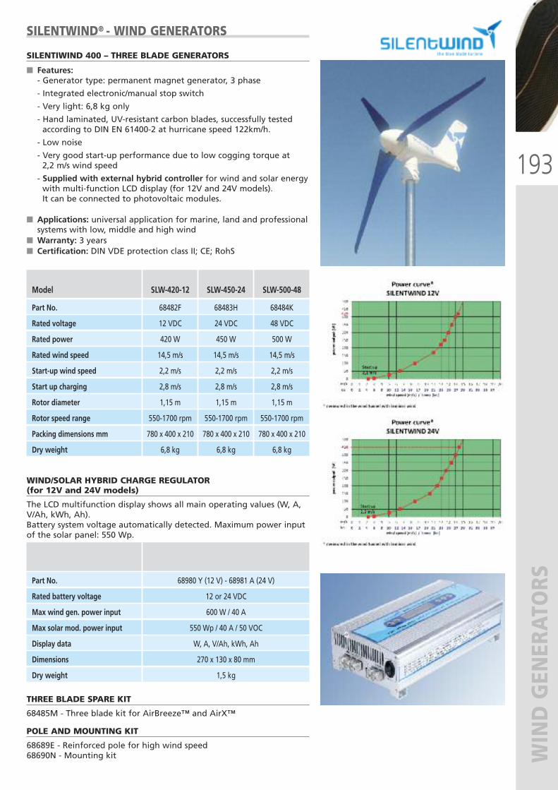
193
WIND GENERATORS
WIND/SOLAR HYBRID CHARGE REGULATOR(for 12V and 24V models)
The LCD multifunction display shows all main operating values (W, A,V/Ah, kWh, Ah).Battery system voltage automatically detected. Maximum power inputof the solar panel: 550 Wp.
THREE BLADE SPARE KIT
68485M - Three blade kit for AirBreeze™ and AirX™
POLE AND MOUNTING KIT
68689E - Reinforced pole for high wind speed68690N - Mounting kit
Part No. 68980 Y (12 V) - 68981 A (24 V)
Rated battery voltage 12 or 24 VDC
Max wind gen. power input 600 W / 40 A
Max solar mod. power input 550 Wp / 40 A / 50 VOC
Display data W, A, V/Ah, kWh, Ah
Dimensions 270 x 130 x 80 mm
Dry weight 1,5 kg
Model SLW-420-12 SLW-450-24 SLW-500-48
Part No. 68482F 68483H 68484K
Rated voltage 12 VDC 24 VDC 48 VDC
Rated power 420 W 450 W 500 W
Rated wind speed 14,5 m/s 14,5 m/s 14,5 m/s
Start-up wind speed 2,2 m/s 2,2 m/s 2,2 m/s
Start up charging 2,8 m/s 2,8 m/s 2,8 m/s
Rotor diameter 1,15 m 1,15 m 1,15 m
Rotor speed range 550-1700 rpm 550-1700 rpm 550-1700 rpm
Packing dimensions mm 780 x 400 x 210 780 x 400 x 210 780 x 400 x 210
Dry weight 6,8 kg 6,8 kg 6,8 kg
SILENTWIND® - WIND GENERATORS
SILENTIWIND 400 – THREE BLADE GENERATORS
� Features:- Generator type: permanent magnet generator, 3 phase
- Integrated electronic/manual stop switch
- Very light: 6,8 kg only
- Hand laminated, UV-resistant carbon blades, successfully testedaccording to DIN EN 61400-2 at hurricane speed 122km/h.
- Low noise
- Very good start-up performance due to low cogging torque at2,2 m/s wind speed
- Supplied with external hybrid controller for wind and solar energywith multi-function LCD display (for 12V and 24V models). It can be connected to photovoltaic modules.
� Applications: universal application for marine, land and professionalsystems with low, middle and high wind
� Warranty: 3 years� Certification: DIN VDE protection class II; CE; RohS
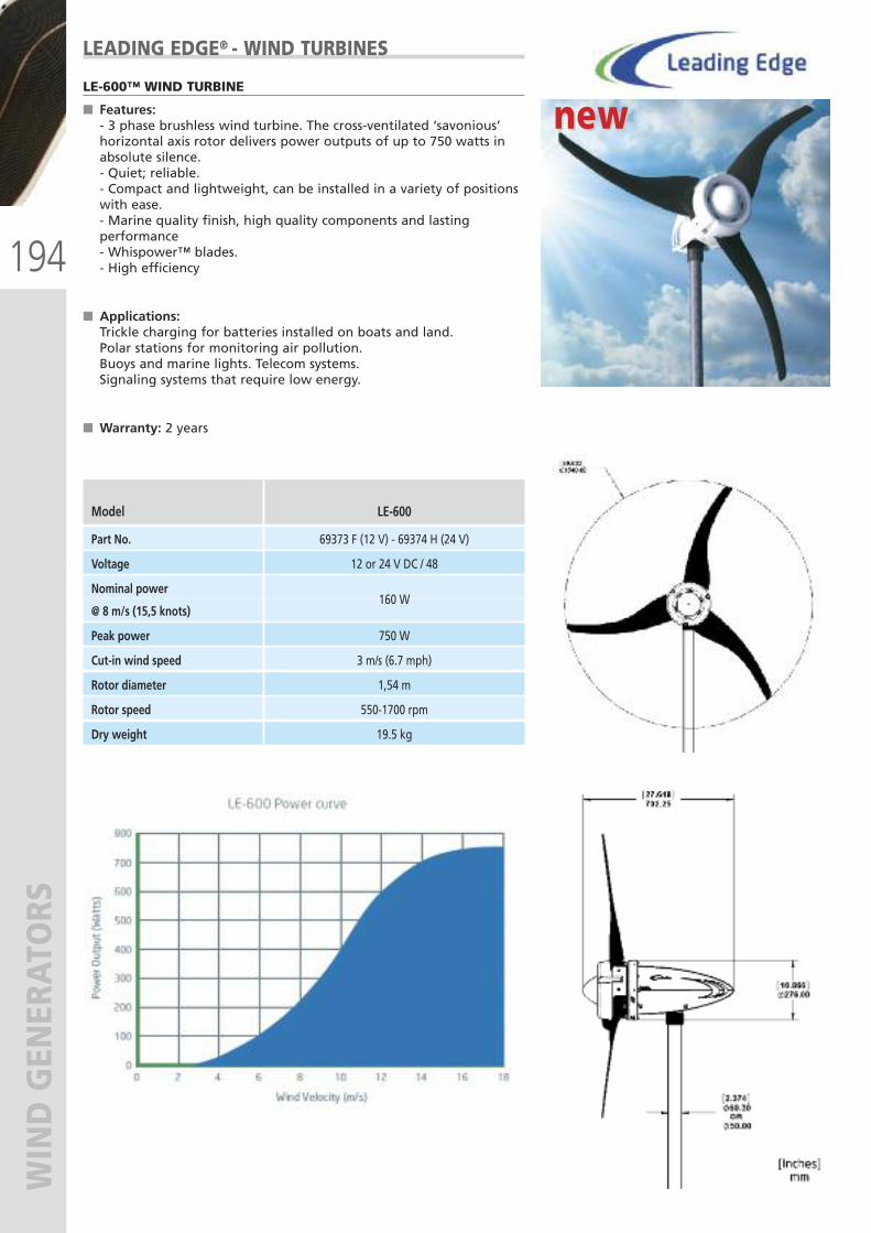
194
WIND GENERATORS
LEADING EDGE® - WIND TURBINES
LE-600™ WIND TURBINE
� Features:- 3 phase brushless wind turbine. The cross-ventilated ‘savonious’horizontal axis rotor delivers power outputs of up to 750 watts inabsolute silence.- Quiet; reliable.- Compact and lightweight, can be installed in a variety of positionswith ease.- Marine quality finish, high quality components and lastingperformance- Whispower™ blades.- High efficiency
� Applications:Trickle charging for batteries installed on boats and land.Polar stations for monitoring air pollution.Buoys and marine lights. Telecom systems.Signaling systems that require low energy.
� Warranty: 2 years
Model LE-600
Part No. 69373 F (12 V) - 69374 H (24 V)
Voltage 12 or 24 V DC / 48
Nominal power
@ 8 m/s (15,5 knots)160 W
Peak power 750 W
Cut-in wind speed 3 m/s (6.7 mph)
Rotor diameter 1,54 m
Rotor speed 550-1700 rpm
Dry weight 19.5 kg
new new
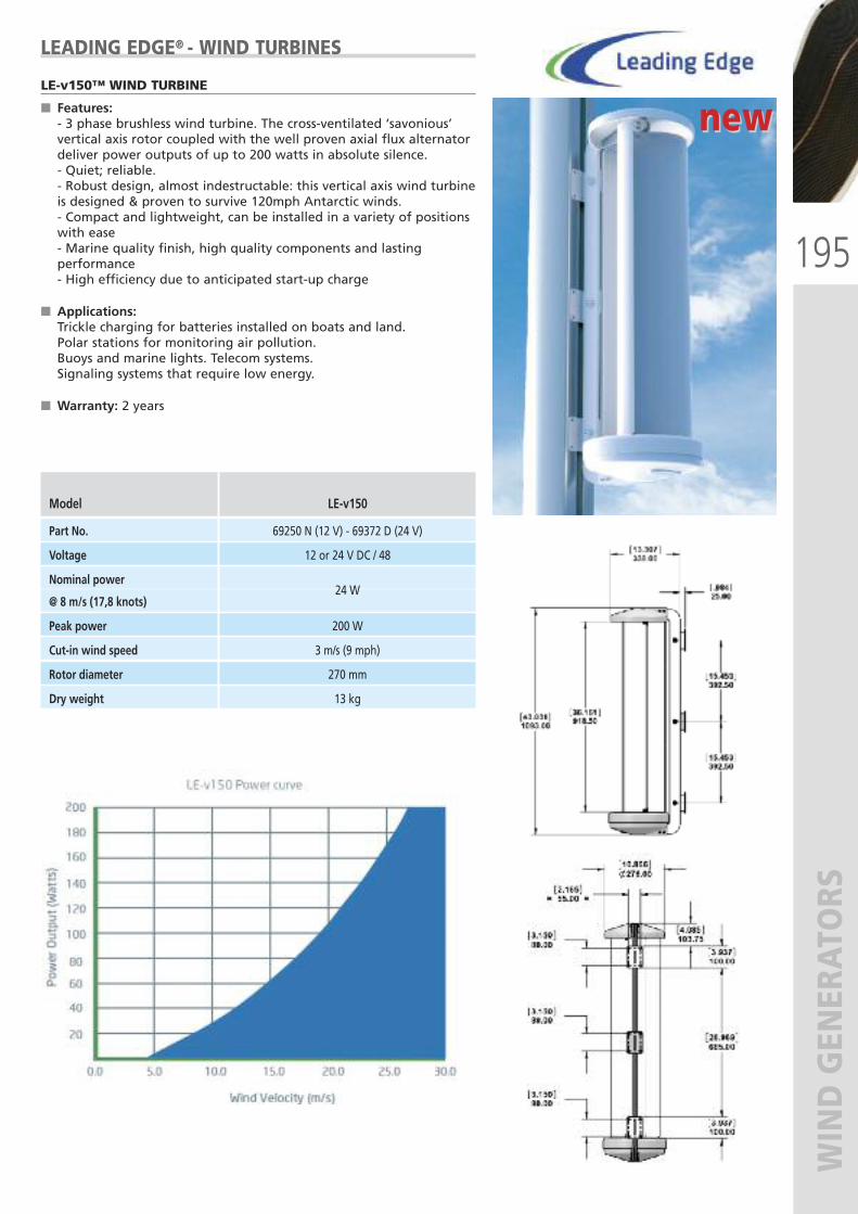
195
WIND GENERATORS
LEADING EDGE® - WIND TURBINES
LE-v150™ WIND TURBINE
� Features:- 3 phase brushless wind turbine. The cross-ventilated ‘savonious’vertical axis rotor coupled with the well proven axial flux alternatordeliver power outputs of up to 200 watts in absolute silence.- Quiet; reliable.- Robust design, almost indestructable: this vertical axis wind turbineis designed & proven to survive 120mph Antarctic winds.- Compact and lightweight, can be installed in a variety of positionswith ease- Marine quality finish, high quality components and lastingperformance- High efficiency due to anticipated start-up charge
� Applications:Trickle charging for batteries installed on boats and land.Polar stations for monitoring air pollution.Buoys and marine lights. Telecom systems.Signaling systems that require low energy.
� Warranty: 2 years
Model LE-v150
Part No. 69250 N (12 V) - 69372 D (24 V)
Voltage 12 or 24 V DC / 48
Nominal power
@ 8 m/s (17,8 knots)24 W
Peak power 200 W
Cut-in wind speed 3 m/s (9 mph)
Rotor diameter 270 mm
Dry weight 13 kg
new new
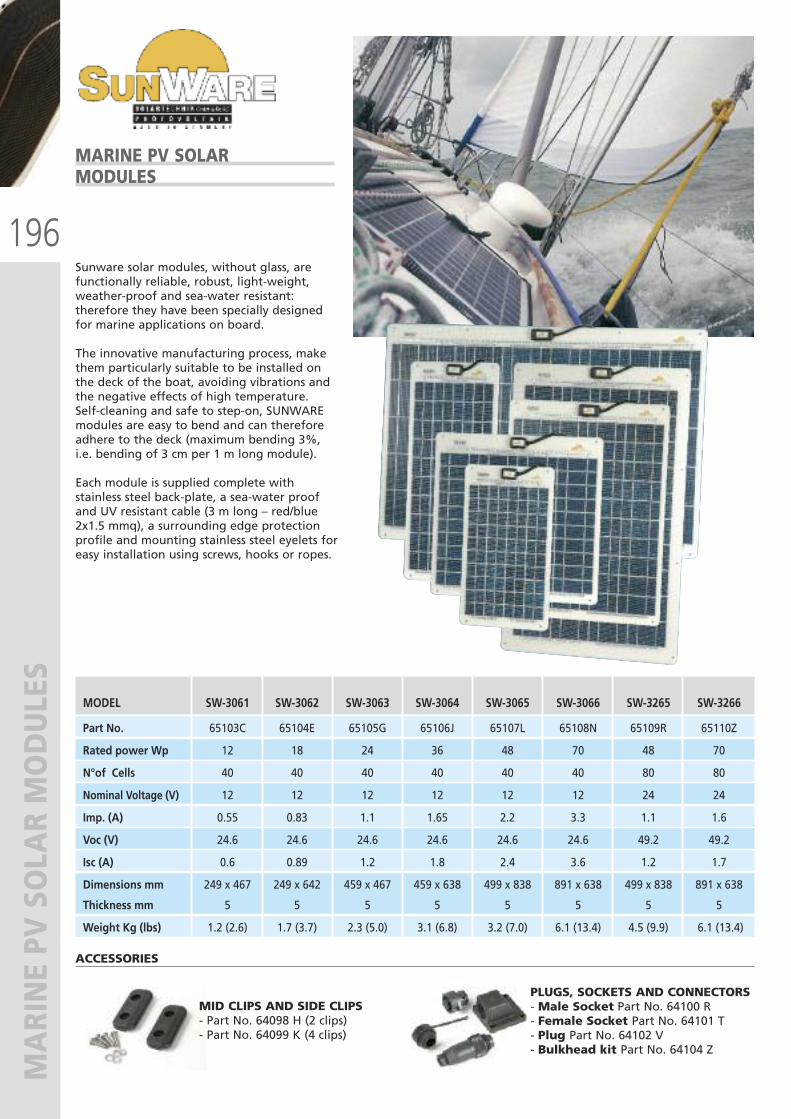
196
MARINE PV SOLAR MODULES
Sunware solar modules, without glass, arefunctionally reliable, robust, light-weight,weather-proof and sea-water resistant:therefore they have been specially designedfor marine applications on board.
The innovative manufacturing process, makethem particularly suitable to be installed onthe deck of the boat, avoiding vibrations andthe negative effects of high temperature.Self-cleaning and safe to step-on, SUNWAREmodules are easy to bend and can thereforeadhere to the deck (maximum bending 3%,i.e. bending of 3 cm per 1 m long module).
Each module is supplied complete withstainless steel back-plate, a sea-water proofand UV resistant cable (3 m long – red/blue2x1.5 mmq), a surrounding edge protectionprofile and mounting stainless steel eyelets foreasy installation using screws, hooks or ropes.
MARINE PV SOLARMODULES
MID CLIPS AND SIDE CLIPS- Part No. 64098 H (2 clips) - Part No. 64099 K (4 clips)
PLUGS, SOCKETS AND CONNECTORS- Male Socket Part No. 64100 R - Female Socket Part No. 64101 T- Plug Part No. 64102 V- Bulkhead kit Part No. 64104 Z
ACCESSORIES
MODEL SW-3061 SW-3062 SW-3063 SW-3064 SW-3065 SW-3066 SW-3265 SW-3266
Part No. 65103C 65104E 65105G 65106J 65107L 65108N 65109R 65110Z
Rated power Wp 12 18 24 36 48 70 48 70
N°of Cells 40 40 40 40 40 40 80 80
Nominal Voltage (V) 12 12 12 12 12 12 24 24
Imp. (A) 0.55 0.83 1.1 1.65 2.2 3.3 1.1 1.6
Voc (V) 24.6 24.6 24.6 24.6 24.6 24.6 49.2 49.2
Isc (A) 0.6 0.89 1.2 1.8 2.4 3.6 1.2 1.7
Dimensions mm 249 x 467 249 x 642 459 x 467 459 x 638 499 x 838 891 x 638 499 x 838 891 x 638
Thickness mm 5 5 5 5 5 5 5 5
Weight Kg (lbs) 1.2 (2.6) 1.7 (3.7) 2.3 (5.0) 3.1 (6.8) 3.2 (7.0) 6.1 (13.4) 4.5 (9.9) 6.1 (13.4)

197
MARINE PV SOLAR MODULES
Apolloflex™ Monocrystalline solar modules are specially designed foruse in all environments, including saltwater environments. Themodules are maintenance free, long living and weatherproof.
� Flexible panels, they are ideal for mounting on roundedroofs and curved surfaces.- Especially designed for motorboat and sailboat decks,motorhomes, caravans and conversion vans. They can be glued orscrewed to the surface.- Safe to step-on and unbreakable- Lightweight (3,6 kg/ m² only) and aerodynamic- These thin solar panels (3 mm onlY) feature a reduced windresistance on vehicles and increase overall fuel efficiency, becausethey do not produce friction.
� High efficiency- The ApolloFlex ™ innovative technology in manufacturing cellsallows an efficiency of 50% higher than conventional cells.- They are efficient in every light conditions, even with 2 diodes percell under shadow- They produce 100W / m² power
� Robust and durable- AplloFlex™ solar panels are ETFE laminated. Fiberglass backplate.Supplied with 5 m cable (1,5 mm²)
Certifications: UL 1703, IEC 61646/61730, JEC, ICC-ES-AC365
Warranty: 3 years
APOLLOFLEX™ SEMI FLEXIBLEMONOCRYSTALLINE SOLAR PANELS
Pmax(I) Vmp(II) Imp(III) Voc(IV) Isc(V) Dimensions WeightModel Part No. Watt Volt Amp Volt Amp mm kg
Mono 35 68508X 35,7 19,04 1,85 23,32 1,97 430 x 540 x 2 1,0
Mono 70 68510H 70 18,48 3,70 22,64 3,94 785 x 540 x 2 2,4
Mono 107 68509Z 107 19,04 5,90 23,32 6,27 1168 x 540 x 2 2,8
TECHNICAL SPECIFICATIONS
(I)Pmax: Nominal capacity(II)Vmp: Max voltage
(III)Imp: Max current(IV)Voc: Open circuit voltage
(V)Isc: Short circuit current
new new

198
MARINE PV SOLAR MODULES
UFLEX® semi-flexible solar modules provideclean and reliable power even in adverseweather conditions. They are robust andresistant to corrosion, lightweight and ultra-thin; therefore easily usable in variousapplications.
They may slightly bend, so they can bemounted even on curved surfaces. They aresafe to step-on and anti-slip, thereforeparticularly suitable to be installed on thedeck of a boat.
The high-performance cells are multi-crystalline, the frames are made of silvercoloured anodized aluminum: can besupplied, on request, also black or whiteframes.
Junction box protection category: IP67Temperature range: -40°C÷85°C
Warranty: 5 years
UFLEX® -SEMI-FLEXIBLESOLAR PANELS
Pmax(I) Vmp(II) Imp(III) Voc(IV) Isc(V) Dimensions WeightModel Part No. Watt Volt Amp Volt Amp mm kg
UMS25 68332K 25 18,86 1,38 22,21 1,47 571 x 342 x 10 1,4
UMS50 68333M 50 17,93 3,09 21,74 3,30 571 x 654 x 10 2,7
UMS100 68334P 100 18,21 5,79 21,96 6,16 1039 x 654 x 10 4,8
TECHNICAL SPECIFICATIONS AT STANDARD ETC TEST (1000W/ m², 25°C, AM 1,5):
POWER CURVE I-V FOR UMS100 PANEL:
(I)Pmax: Nominal capacity(II)Vmp: Max voltage
(III)Imp: Max current(IV)Voc: Open circuit voltage
(V)Isc: Short circuit current
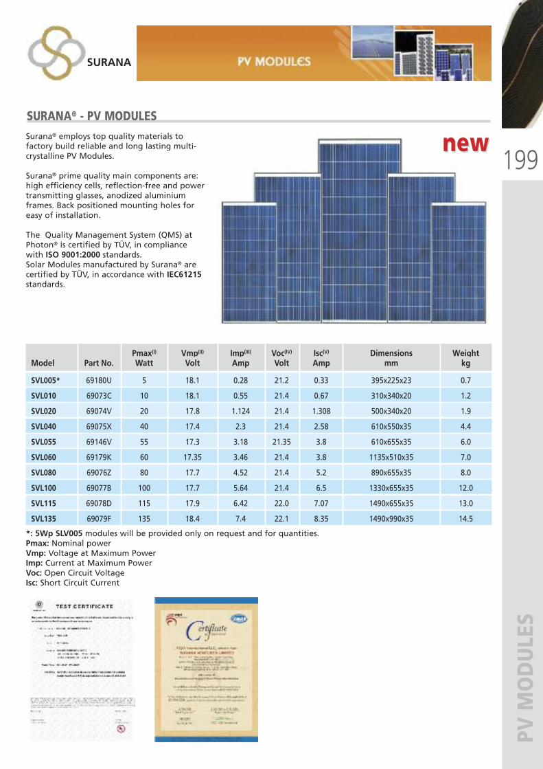
199
PV MODULES
SURANA® - PV MODULESSurana® employs top quality materials tofactory build reliable and long lasting multi-crystalline PV Modules.
Surana® prime quality main components are:high efficiency cells, reflection-free and powertransmitting glasses, anodized aluminiumframes. Back positioned mounting holes foreasy of installation.
The Quality Management System (QMS) atPhoton® is certified by TÜV, in compliancewith ISO 9001:2000 standards.Solar Modules manufactured by Surana® arecertified by TÜV, in accordance with IEC61215standards.
*: 5Wp SLV005 modules will be provided only on request and for quantities.Pmax: Nominal powerVmp: Voltage at Maximum PowerImp: Current at Maximum PowerVoc: Open Circuit VoltageIsc: Short Circuit Current
Pmax(I) Vmp(II) Imp(III) Voc(IV) Isc(V) Dimensions WeightModel Part No. Watt Volt Amp Volt Amp mm kg
SVL005* 69180U 5 18.1 0.28 21.2 0.33 395x225x23 0.7
SVL010 69073C 10 18.1 0.55 21.4 0.67 310x340x20 1.2
SVL020 69074V 20 17.8 1.124 21.4 1.308 500x340x20 1.9
SVL040 69075X 40 17.4 2.3 21.4 2.58 610x550x35 4.4
SVL055 69146V 55 17.3 3.18 21.35 3.8 610x655x35 6.0
SVL060 69179K 60 17.35 3.46 21.4 3.8 1135x510x35 7.0
SVL080 69076Z 80 17.7 4.52 21.4 5.2 890x655x35 8.0
SVL100 69077B 100 17.7 5.64 21.4 6.5 1330x655x35 12.0
SVL115 69078D 115 17.9 6.42 22.0 7.07 1490x655x35 13.0
SVL135 69079F 135 18.4 7.4 22.1 8.35 1490x990x35 14.5
SURANA
new new
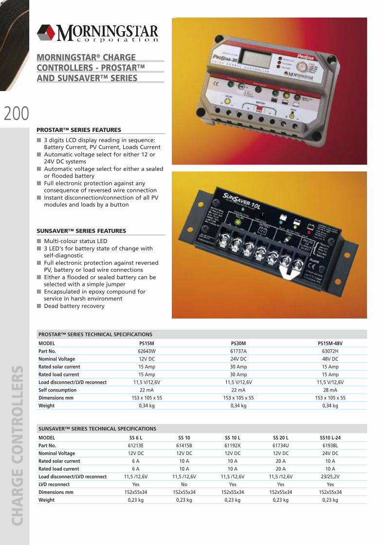
200
CHARG
E CO
NTROLLERS
PROSTAR™ SERIES FEATURES
� 3 digits LCD display reading in sequence:Battery Current, PV Current, Loads Current
� Automatic voltage select for either 12 or24V DC systems
� Automatic voltage select for either a sealedor flooded battery
� Full electronic protection against anyconsequence of reversed wire connection
� Instant disconnection/connection of all PVmodules and loads by a button
SUNSAVER™ SERIES FEATURES
� Multi-colour status LED� 3 LED’s for battery state of change withself-diagnostic
� Full electronic protection against reversedPV, battery or load wire connections
� Either a flooded or sealed battery can beselected with a simple jumper
� Encapsulated in epoxy compound forservice in harsh environment
� Dead battery recovery
MORNINGSTAR® CHARGECONTROLLERS - PROSTAR™ AND SUNSAVER™ SERIES
PROSTAR™ SERIES TECHNICAL SPECIFICATIONS
MODEL PS15M PS30M PS15M-48V
Part No. 62643W 61737A 63072H
Nominal Voltage 12V DC 24V DC 48V DC
Rated solar current 15 Amp 30 Amp 15 Amp
Rated load current 15 Amp 30 Amp 15 Amp
Load disconnect/LVD reconnect 11,5 V/12,6V 11,5 V/12,6V 11,5 V/12,6V
Self consumption 22 mA 22 mA 28 mA
Dimensions mm 153 x 105 x 55 153 x 105 x 55 153 x 105 x 55
Weight 0,34 kg 0,34 kg 0,34 kg
SUNSAVER™ SERIES TECHNICAL SPECIFICATIONS
MODEL SS 6 L SS 10 SS 10 L SS 20 L SS10 L-24
Part No. 61213E 61415B 61192X 61734U 61938L
Nominal Voltage 12V DC 12V DC 12V DC 12V DC 24V DC
Rated solar current 6 A 10 A 10 A 20 A 10 A
Rated load current 6 A 10 A 10 A 20 A 10 A
Load disconnect/LVD reconnect 11,5 /12,6V 11,5 /12,6V 11,5 /12,6V 11,5 /12,6V 23/25,2V
LVD reconnect Yes No Yes Yes Yes
Dimensions mm 152x55x34 152x55x34 152x55x34 152x55x34 152x55x34
Weight 0,23 kg 0,23 kg 0,23 kg 0,23 kg 0,23 kg

201
CHARG
E CO
NTROLLERS
SunSaver DUO™ is a two battery solarcontroller with remote adjustable meter
FEATURES
� Will charge two separate and isolatedbatteries at the same time based on userselectable priorities
� Includes a backlit remote meter with LEDdisplay which may be mounted in or on awall and displays information about thesolar power system
� User adjustable via DIP switch orconnection to a PC
� Two battery charging eliminates the addedcost of two separate solar charging systemsand the need for isolation between thebatteries
� Will not be damaged by wiring mistakesduring installation
� Epoxy encapsulated for environmentalprotection
� Options: Remote Temperature Sensor
ELECTRONIC PROTECTION
� PV:Over Current, Short Circuit� Reverse polarity� Lightning� High Temperature� Reverse Current at Night
CERTIFICATIONS
� CE
MORNINGSTAR®CHARGE CONTROLLERS -SUNSAVER DUO™
TECHNICAL SPECIFICATIONS
MODEL SunSaver DUO™
Part No. 66129 C
Battery Voltage 12 Volt
Rated Solar Input 25 Amp
Max Solar Voltage 30 Volt
Max battery Voltage 15 Volt
Self Consumption 25 mA (controller and meter)
Operating Ambient Temperature -40°C a +40°C
Dimensions 170 x 56 x 41 mm
Meter Hole size 76 mm
Largest wire 16 mm²
Weight 0,26 kg
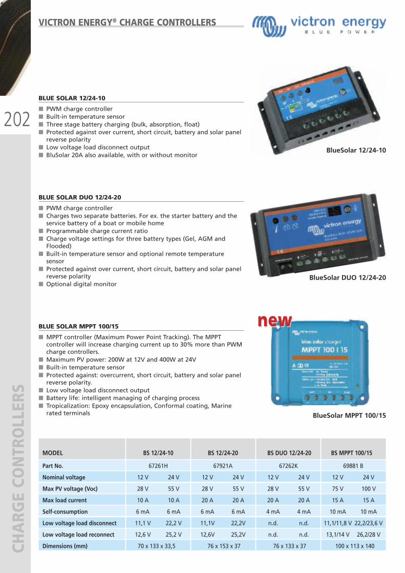
202
CHARG
E CO
NTROLLERS
MODEL BS 12/24-10 BS 12/24-20 BS DUO 12/24-20 BS MPPT 100/15
Part No. 67261H 67921A 67262K 69881 B
Nominal voltage 12 V 24 V 12 V 24 V 12 V 24 V 12 V 24 V
Max PV voltage (Voc) 28 V 55 V 28 V 55 V 28 V 55 V 75 V 100 V
Max load current 10 A 10 A 20 A 20 A 20 A 20 A 15 A 15 A
Self-consumption 6 mA 6 mA 6 mA 6 mA 4 mA 4 mA 10 mA 10 mA
Low voltage load disconnect 11,1 V 22,2 V 11,1V 22,2V n.d. n.d. 11,1/11,8 V 22,2/23,6 V
Low voltage load reconnect 12,6 V 25,2 V 12,6V 25,2V n.d. n.d. 13,1/14 V 26,2/28 V
Dimensions (mm) 70 x 133 x 33,5 76 x 153 x 37 76 x 133 x 37 100 x 113 x 140
VICTRON ENERGY® CHARGE CONTROLLERS
BLUE SOLAR 12/24-10
� PWM charge controller� Built-in temperature sensor� Three stage battery charging (bulk, absorption, float) � Protected against over current, short circuit, battery and solar panelreverse polarity
� Low voltage load disconnect output� BluSolar 20A also available, with or without monitor
BLUE SOLAR DUO 12/24-20
� PWM charge controller� Charges two separate batteries. For ex. the starter battery and theservice battery of a boat or mobile home
� Programmable charge current ratio� Charge voltage settings for three battery types (Gel, AGM andFlooded)
� Built-in temperature sensor and optional remote temperaturesensor
� Protected against over current, short circuit, battery and solar panelreverse polarity
� Optional digital monitor
BLUE SOLAR MPPT 100/15
� MPPT controller (Maximum Power Point Tracking). The MPPTcontroller will increase charging current up to 30% more than PWMcharge controllers.
� Maximum PV power: 200W at 12V and 400W at 24V� Built-in temperature sensor� Protected against: overcurrent, short circuit, battery and solar panelreverse polarity.
� Low voltage load disconnect output � Battery life: intelligent managing of charging process� Tropicalization: Epoxy encapsulation, Conformal coating, Marinerated terminals
BlueSolar 12/24-10
BlueSolar DUO 12/24-20
BlueSolar MPPT 100/15
new new
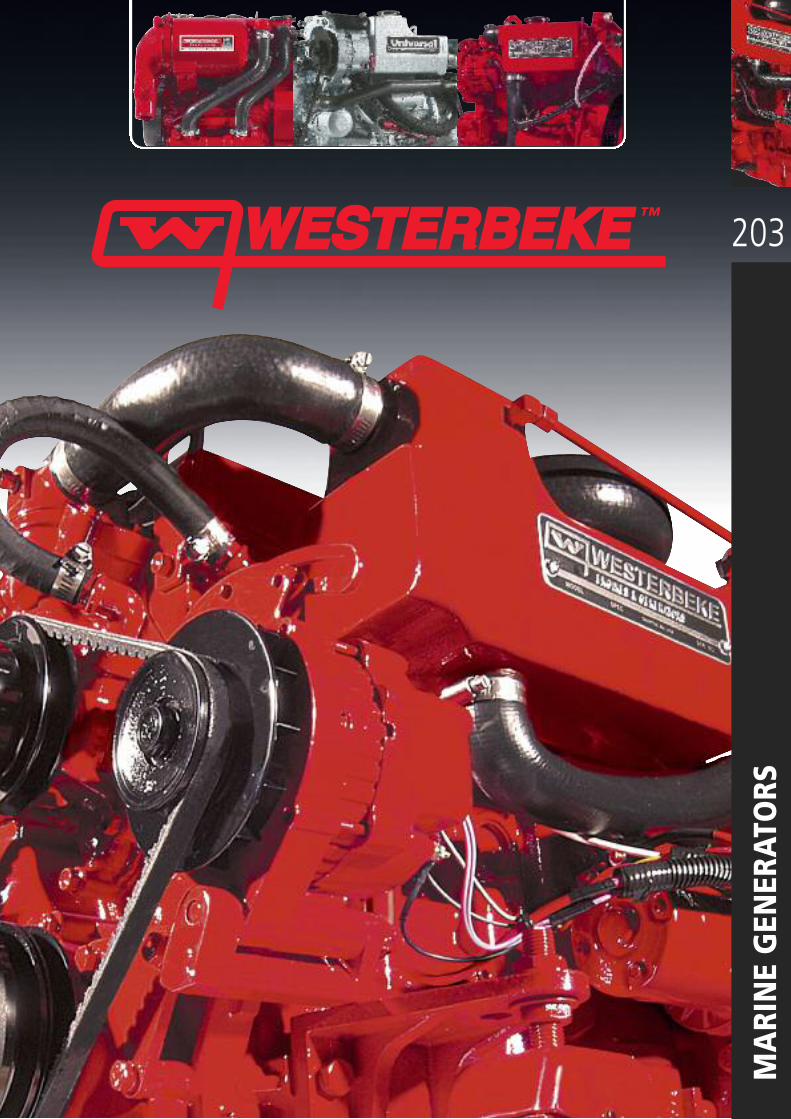
203
MARINE GENERATORS
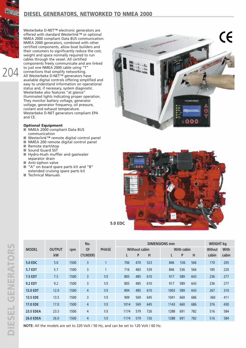
204
DIESEL GENERATORS
DIESEL GENERATORS, NETWORKED TO NMEA 2000
Westerbeke D-NET™ electronic generators areoffered with standard Westerlink™ or optionalNMEA 2000 compliant Data BUS communication.NMEA 2000 generators, combined with othercertified components, allow boat builders andtheir costumers to significantly reduce the cost,weight and space normally required to runcables through the vessel. All certifiedcomponents freely communicate and are linkedto just one NMEA 2000 cable using “T”connections that simplify networking.All Westerbeke D-NET™ generators haveavailable digital controls offering simplified andeasy to understand information on operationalstatus and, if necessary, system diagnostic.Westerbeke also features “at glance”illuminated lights indicating proper operation.They monitor battery voltage, generatorvoltage, generator frequency, oil pressure,coolant and exhaust temperature.Westerbeke D-NET generators compliant EPAand CE.
Optional Equipment� NMEA 2000 compliant Data BUScommunication
� Westerlink™ remote digital control panel� NMEA 200 remote digital control panel� Remote start/stop� Sound Guard SST� Hydro-Hush muffler and gas/waterseparator drain
� Anti-siphon valve� “A” on board spare parts kit and “B”extended cruising spare parts kit
� Technical Manuals
No. DIMENSIONS mm WEIGHT kg MODEL OUTPUT rpm OF PHASE Without cabin With cabin Without With kW CYLINDERS L P H L P H cabin cabin
5.0 EDC 5.0 1500 3 1 706 470 523 846 536 566 170 205
5.7 EDT 5.7 1500 3 1 716 483 539 846 536 566 185 220
7.5 EDT 7.5 1500 3 1/3 805 485 610 917 589 643 236 277
9.2 EDT 9.2 1500 3 1/3 805 485 610 917 589 643 236 277
12.0 EDT 12.0 1500 4 1/3 894 485 610 1003 589 643 267 310
13.5 EDE 13.5 1500 3 1/3 909 569 645 1041 660 686 360 411
17.0 EDE 17.0 1500 4 1/3 1014 569 645 1143 660 686 376 430
23.5 EDEA 23.5 1500 4 1/3 1174 579 726 1288 691 782 516 584
26.0 EDEA 26.0 1500 4 1/3 1174 579 726 1288 691 782 516 584
5.0 EDC
NOTE: All the models are set to 220 Volt / 50 Hz, and can be set to 120 Volt / 60 Hz.
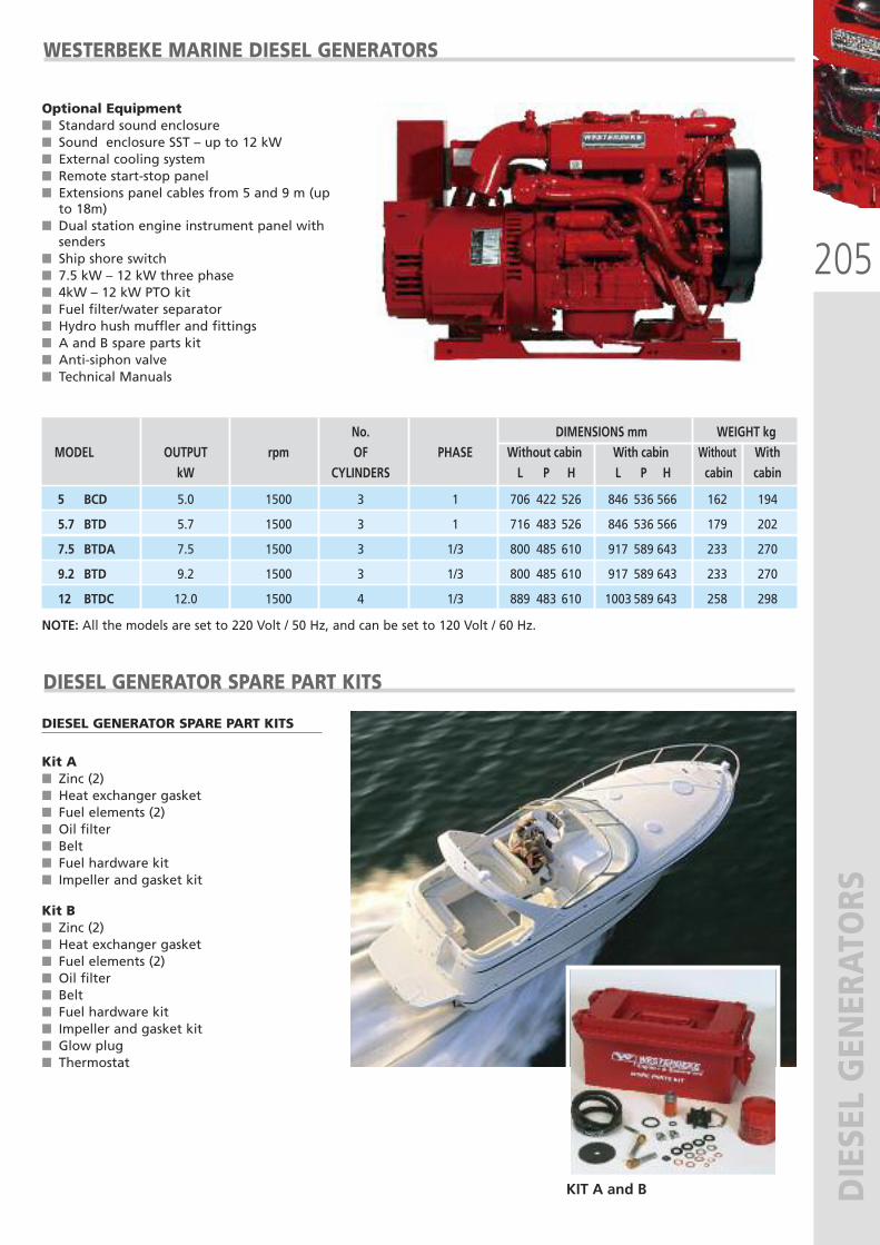
205
DIESEL GENERATORS
WESTERBEKE MARINE DIESEL GENERATORS
Optional Equipment� Standard sound enclosure� Sound enclosure SST – up to 12 kW� External cooling system� Remote start-stop panel� Extensions panel cables from 5 and 9 m (upto 18m)
� Dual station engine instrument panel withsenders
� Ship shore switch� 7.5 kW – 12 kW three phase� 4kW – 12 kW PTO kit� Fuel filter/water separator� Hydro hush muffler and fittings� A and B spare parts kit� Anti-siphon valve� Technical Manuals
No. DIMENSIONS mm WEIGHT kg MODEL OUTPUT rpm OF PHASE Without cabin With cabin Without With kW CYLINDERS L P H L P H cabin cabin
5 BCD 5.0 1500 3 1 706 422 526 846 536 566 162 194
5.7 BTD 5.7 1500 3 1 716 483 526 846 536 566 179 202
7.5 BTDA 7.5 1500 3 1/3 800 485 610 917 589 643 233 270
9.2 BTD 9.2 1500 3 1/3 800 485 610 917 589 643 233 270
12 BTDC 12.0 1500 4 1/3 889 483 610 1003 589 643 258 298
NOTE: All the models are set to 220 Volt / 50 Hz, and can be set to 120 Volt / 60 Hz.
DIESEL GENERATOR SPARE PART KITS
DIESEL GENERATOR SPARE PART KITS
Kit A� Zinc (2)� Heat exchanger gasket� Fuel elements (2)� Oil filter� Belt� Fuel hardware kit� Impeller and gasket kit
Kit B� Zinc (2)� Heat exchanger gasket� Fuel elements (2)� Oil filter� Belt� Fuel hardware kit� Impeller and gasket kit� Glow plug� Thermostat
KIT A and B
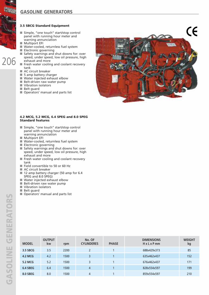
206
GASOLINE GENERATORS
GASOLINE GENERATORS
3.5 SBCG Standard Equipment
� Simple, “one touch” start/stop controlpanel with running hour meter andwarning annunciation
� Multiport EFI� Water-cooled, returnless fuel system� Electronic governing� Safety warnings and shut downs for: overspeed, under speed, low oil pressure, highexhaust and more
� Fresh water cooling and coolant recoverytank
� AC circuit breaker� 5 amp battery charger� Water injected exhaust elbow� Belt-driven raw water pump� Vibration isolators� Belt guard� Operators’ manual and parts list
4.2 MCG, 5.2 MCG, 6.4 SPEG and 8.0 SPEGStandard features
� Simple, “one touch” start/stop controlpanel with running hour meter andwarning annunciation
� Multiport EFI� Water-cooled, returnless fuel system� Electronic governing� Safety warnings and shut downs for: overspeed, under speed, low oil pressure, highexhaust and more
� Fresh water cooling and coolant recoverytank
� Field convertible to 50 or 60 Hz� AC circuit breaker� 12 amp battery charger (50 amp for 6.4SPEG and 8.0 SPEG)
� Water injected exhaust elbow� Belt-driven raw water pump� Vibration isolators� Belt guard� Operators’ manual and parts list
OUTPUT No. OF DIMENSIONS WEIGHTMODEL kw rpm CYLINDERES PHASE H x L x P mm kg
3.5 SBCG 3.5 2200 2 1 688x429x373 85
4.2 MCG 4.2 1500 3 1 635x462x437 152
5.2 MCG 5.2 1500 3 1 676x462x437 171
6.4 SBEG 6.4 1500 4 1 828x554x597 199
8.0 SBEG 8.0 1500 4 1 859x554x597 210

207
SILENCING AND EXHAUST SYSTEM
S
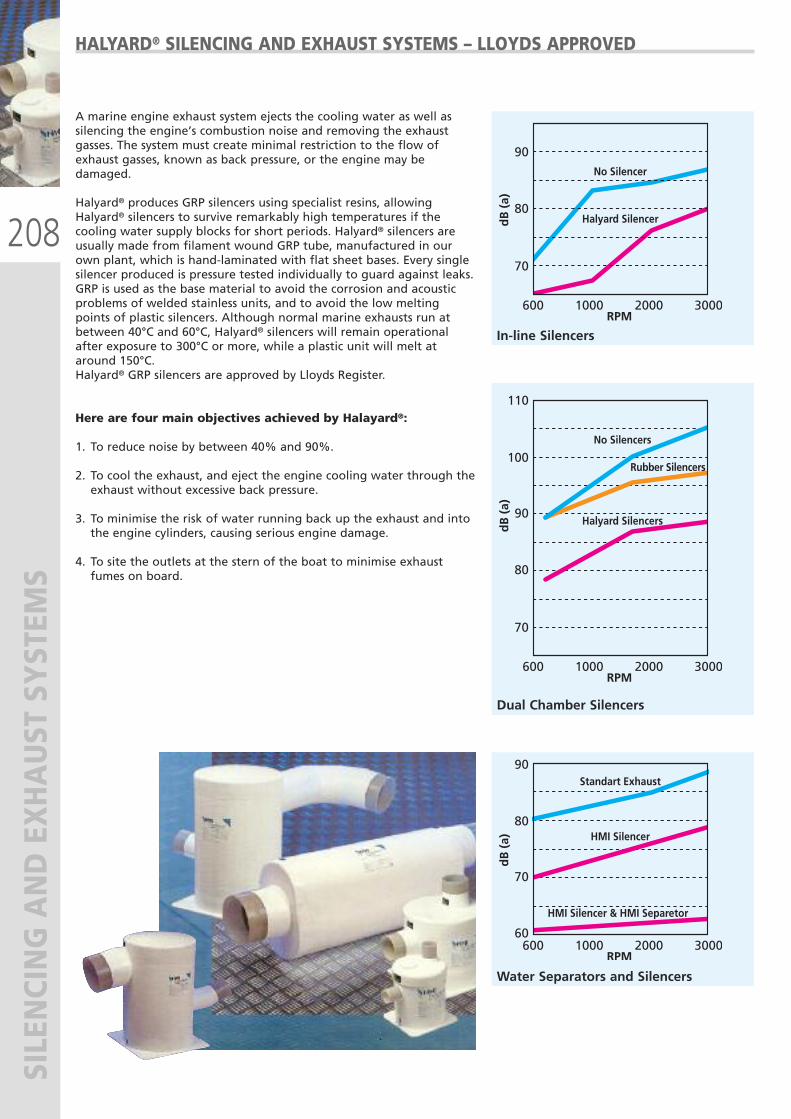
208
SILENCING AND EXHAUST SYSTEM
S
A marine engine exhaust system ejects the cooling water as well assilencing the engine’s combustion noise and removing the exhaustgasses. The system must create minimal restriction to the flow ofexhaust gasses, known as back pressure, or the engine may bedamaged.
Halyard® produces GRP silencers using specialist resins, allowingHalyard® silencers to survive remarkably high temperatures if thecooling water supply blocks for short periods. Halyard® silencers areusually made from filament wound GRP tube, manufactured in ourown plant, which is hand-laminated with flat sheet bases. Every singlesilencer produced is pressure tested individually to guard against leaks. GRP is used as the base material to avoid the corrosion and acousticproblems of welded stainless units, and to avoid the low meltingpoints of plastic silencers. Although normal marine exhausts run atbetween 40°C and 60°C, Halyard® silencers will remain operationalafter exposure to 300°C or more, while a plastic unit will melt ataround 150°C. Halyard® GRP silencers are approved by Lloyds Register.
Here are four main objectives achieved by Halayard®:
1. To reduce noise by between 40% and 90%.
2. To cool the exhaust, and eject the engine cooling water through theexhaust without excessive back pressure.
3. To minimise the risk of water running back up the exhaust and intothe engine cylinders, causing serious engine damage.
4. To site the outlets at the stern of the boat to minimise exhaustfumes on board.
In-line Silencers
Water Separators and Silencers
Dual Chamber Silencers
HALYARD® SILENCING AND EXHAUST SYSTEMS – LLOYDS APPROVED
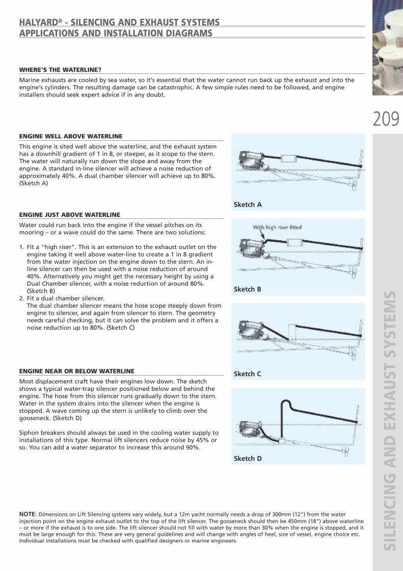
209
SILENCING AND EXHAUST SYSTEM
S
HALYARD® - SILENCING AND EXHAUST SYSTEMSAPPLICATIONS AND INSTALLATION DIAGRAMS
ENGINE WELL ABOVE WATERLINE
This engine is sited well above the waterline, and the exhaust systemhas a downhill gradient of 1 in 8, or steeper, as it scope to the stern.The water will naturally run down the slope and away from theengine. A standard in-line silencer will achieve a noise reduction ofapproximately 40%. A dual chamber silencer will achieve up to 80%.(Sketch A)
ENGINE JUST ABOVE WATERLINE
Water could run back into the engine if the vessel pitches on itsmooring – or a wave could do the same. There are two solutions:
1. Fit a "high riser". This is an extension to the exhaust outlet on theengine taking it well above water-line to create a 1 in 8 gradientfrom the water injection on the engine down to the stern. An in-line silencer can then be used with a noise reduction of around40%. Alternatively you might get the necessary height by using aDual Chamber silencer, with a noise reduction of around 80%.(Sketch B)
2. Fit a dual chamber silencer. The dual chamber silencer means the hose scope steeply down fromengine to silencer, and again from silencer to stern. The geometryneeds careful checking, but it can solve the problem and it offers anoise reduction up to 80%. (Sketch C)
ENGINE NEAR OR BELOW WATERLINE
Most displacement craft have their engines low down. The sketchshows a typical water-trap silencer positioned below and behind theengine. The hose from this silencer runs gradually down to the stern.Water in the system drains into the silencer when the engine isstopped. A wave coming up the stern is unlikely to climb over thegooseneck. (Sketch D)
Siphon breakers should always be used in the cooling water supply toinstallations of this type. Normal lift silencers reduce noise by 45% orso. You can add a water separator to increase this around 90%.
Sketch A
Sketch B
Sketch C
Sketch D
WHERE’S THE WATERLINE?
Marine exhausts are cooled by sea water, so it’s essential that the water cannot run back up the exhaust and into theengine’s cylinders. The resulting damage can be catastrophic. A few simple rules need to be followed, and engineinstallers should seek expert advice if in any doubt.
NOTE: Dimensions on Lift Silencing systems vary widely, but a 12m yacht normally needs a drop of 300mm (12") from the waterinjection point on the engine exhaust outlet to the top of the lift silencer. The gooseneck should then be 450mm (18") above waterline– or more if the exhaust is to one side. The lift silencer should not fill with water by more than 30% when the engine is stopped, and itmust be large enough for this. These are very general guidelines and will change with angles of heel, size of vessel, engine choice etc.Individual installations must be checked with qualified designers or marine engineers.
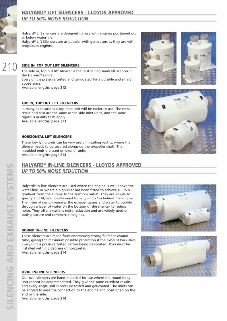
210
SILENCING AND EXHAUST SYSTEM
SHALYARD® LIFT SILENCERS - LLOYDS APPROVEDUP TO 50% NOISE REDUCTION
Halyard® Lift silencers are designed for use with engines positioned on,or below waterline. Halyard® Lift Silencers are as popular with generators as they are withpropulsion engines.
SIDE IN, TOP OUT LIFT SILENCERS
The side in, top out lift silencer is the best selling small lift silencer inthe Halyard® range. Every unit is pressure tested and gel-coated for a durable and smartappearance. Available lengths: page 213
TOP IN, TOP OUT LIFT SILENCERS
In many applications a top inlet unit will be easier to use. The noiseresult and cost are the same as the side inlet units, and the samerigorous quality tests apply.Available lengths: page 213
HORIZONTAL LIFT SILENCERS
These low lying units can be very useful in sailing yachts, where thesilencer needs to be secured alongside the propeller shaft. Themoulded ends are used on smaller units.Available lengths: page 214
HALYARD® IN-LINE SILENCERS - LLOYDS APPROVEDUP TO 50% NOISE REDUCTION
Halyard® in-line silencers are used where the engine is well above thewater-line, or where a high-riser has been fitted to achieve a 1 in 8gradient from the engine to the transom outlet. They are simple tospecify and fit, and ideally need to be 0,5m to 1m behind the engine.The internal design requires the exhaust gasses and water to bubblethrough a layer of water on the bottom of the silencer to reducenoise. They offer excellent noise reduction and are widely used onboth pleasure and commercial engines.
ROUND IN-LINE SILENCERS
These silencers are made from enormously strong filament woundtube, giving the maximum possible protection if the exhaust back-fires.Every unit is pressure tested before being gel-coated. They must beinstalled within 5 degrees of horizontal.Available lengths: page 214
OVAL IN-LINE SILENCERS
Our oval silencers are hand-moulded for use where the round bodyunit cannot be accommodated. They give the same excellent resultsand every single unit is pressure tested and gel-coated. The inlets canbe angled to ease the connection to the engine and positioned on theend or the side.Available lengths: page 214

211
SILENCING AND EXHAUST SYSTEM
S
HALYARD® DUAL CHAMBER SILENCERS - LLOYDS APPROVEDUP TO 80% NOISE REDUCTION
HALYARD® EXHAUST WATER SEPARATORS - LLOYDS APPROVEDNOISE REDUCTION UP TO 90%
Halyard® Dual Chamber silencers is the best wet-exhaust silencer onthe market today.
Exhaust noise reductions of up to 80% can be achieved and the backpressure created by the unit is minimal.
Most units are hand-built with inlet and outlet positioned to suit theparticular craft.
The quality standards applied are designed to give a life in excess often years on a privately owned craft.Available lengths: see page 214
Fitting a water separator into the exhaust toreplace the gooseneck removes water once ithas done its cooling job, draining this quietlyaway below waterline. Back pressure isreduced dramatically. The separator removesthe principal cause of back pressure and stopsthe sploshing noise which accompanies everymarine engine ticking over in a harbour – oron a generator sploshing away in a quiethaven somewhere, to the fury of nearbyboats.
EXHAUST WATER SEPARATORS MS SERIES
The MS Series of exhaust water separatorscovers a wide range of exhaust diameters, forgenerators and propulsion engines withcooling water flow rates of up to 40 liters perminute. The MS unit will remove all but a tinytrickle of water.
Halyard developed the concept of water separation and now designs and produces systems for engines ranging fromsmall diesel generators through to mighty power providers on super-yachts and commercial craft.
HALYARD® CAN SUPPLY ON REQUEST EXHAUST SEPARATORS COMPLETE WITH STANDARD HOSES (UP TO 160°C) ORSILICON HOSES (UP TO 270°C), AND COMPLETE WITH SILICON FITTINGS AND BRONZE SIPHON BREAK.For any further information, please contact our Technical Service.
A mm
269
B mm
90
C mm
269
D mm
73
E mm
100
F mm
38
G mm
38
PART No.
66902 R
HALYARD PART. N°
H012752
MS 4000 SERIES
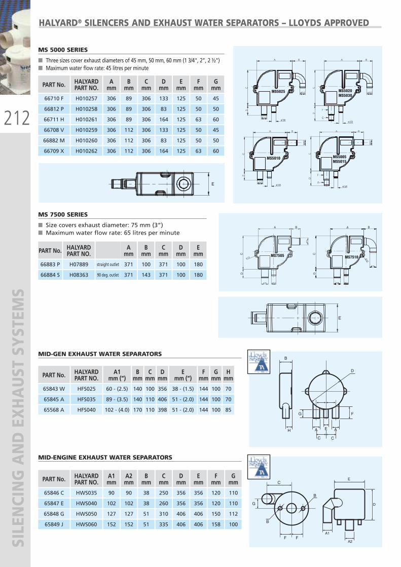
212
SILENCING AND EXHAUST SYSTEM
S
MS5020MS5030
MS7505 MS7510
A B
CD
A B
CD
E
MS5025
MS5010 MS5005MS5015E
MS5020MS5030
MS7505 MS7510
A B
CD
A B
CD
E
MS5025
MS5010 MS5005MS5015E
MS5020MS5030
MS7505 MS7510
A B
CD
A B
CD
E
MS5025
MS5010 MS5005MS5015E
MS5020MS5030
MS7505 MS7510
A B
CD
A B
CD
E
MS5025
MS5010 MS5005MS5015E
HALYARD® SILENCERS AND EXHAUST WATER SEPARATORS – LLOYDS APPROVED
MS 5000 SERIES
� Three sizes cover exhaust diameters of 45 mm, 50 mm, 60 mm (1 3/4", 2”, 2 ½")� Maximum water flow rate: 45 litres per minute
MID-GEN EXHAUST WATER SEPARATORS
MS 7500 SERIES
� Size covers exhaust diameter: 75 mm (3”)� Maximum water flow rate: 65 litres per minute
PART No.
66883 P
HALYARDPART NO.
H07889
Amm
371
66884 S H08363
straight outlet
90 deg. outlet 371
Bmm
100
143
Cmm
371
371
Dmm
100
100
Emm
180
180
PART No.
66710 F
HALYARDPART NO.
66812 P
66711 H
Amm
306
306
306
Bmm
89
89
89
Cmm
306
306
306
Dmm
133
83
164
Emm
125
125
125
Fmm
50
50
63
Gmm
45
50
60
66708 V 306 112 306 133 125 50 45
66882 M 306 112 306 83 125 50 50
66709 X
H010257
H010258
H010261
H010259
H010260
H010262 306 112 306 164 125 63 60
PART No.
65843 W
HALYARDPART NO.
HFS025
A1mm (“)
60 - (2.5)
Emm (“)
38 - (1.5)
Bmm
140
Cmm
100
Dmm
356
Gmm
100
65845 A HFS035 89 - (3.5) 51 - (2.0)140 110 406 100
65568 A HFS040 102 - (4.0) 51 - (2.0)170 110 398 100
Fmm
144
144
144
Hmm
70
70
85
PART No.
65846 C
HALYARDPART NO.
HWS035
A1mm
90
65847 E HWS040 102
65848 G HWS050 127
A2mm
90
102
127
Bmm
38
38
51
Cmm
250
260
310
Dmm
356
356
406
Emm
356
356
406
Fmm
120
120
150
Gmm
110
110
112
65849 J HWS060 152 152 51 335 406 406 158 100
MID-ENGINE EXHAUST WATER SEPARATORS
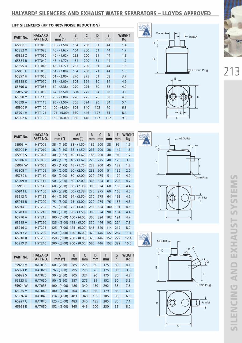
213
SILENCING AND EXHAUST SYSTEM
S
HALYARD® SILENCERS AND EXHAUST WATER SEPARATORS – LLOYDS APPROVED
LIFT SILENCERS (UP TO 40% NOISE REDUCTION)
65850 T HTT005 38 - (1.50) 164 200 51 44 1,4
65852 X
65853 Z
HTT025
HTT030
40 - (1.62)
40 - (1.62)
164
233
200
200
51
51
44
44
1,7
1,8
65854 B
65855 D
HTT040
HTT045
45 - (1.77)
45 - (1.77)
164
233
200
200
51
51
44
44
1,7
1,8
65856 F
65857 H
HTT055
HTT065
51 - (2.00)
51 - (2.00)
164
270
200
275
71
51
44
68
1,8
3,7
65858 K
65896 U
HTT070
HTT085
51 - (2.00)
60 - (2.38)
305
270
324
275
80
60
84
68
4,2
4,0
65897 W
65898 Y
HTT090
HTT110
64 - (2.50)
75 - (3.00)
270
270
275
275
64
76
68
68
3,6
4,0
65899 A
65900 F
HTT115
HTT120
90 - (3.50)
100 - (4.00)
305
305
324
340
90
102
84
70
5,4
6,3
65901 H
65902 K
HTT125
HTT130
125 - (5.00)
150 - (6.00)
360
360
446
446
127
127
83
102
8,4
9,3
PART No. HALYARDPART NO.
Amm (“)
Bmm
Cmm
Dmm
Emm
WEIGHTKg
PART No.
65903 M
HALYARDPART NO.HST005
A1mm (“)38 - (1.50)
A2mm (“)38 - (1.50)
Bmm186
Cmm200
Dmm38
Fmm95
WEIGHTKg1,5
65904 P HST010 38 - (1.50) 38 - (1.50) 233 200 38 142 1,5
65905 S HST025 40 - (1.62) 40 - (1.62) 186 200 40 94 1,7
65906 U HST035 40 - (1.62) 40 - (1.62) 270 275 40 175 3,9
65907 W HST055 45 - (1.75) 45 - (1.75) 233 200 45 139 1,8
65908 Y HST105 50 - (2.00) 50 - (2.00) 233 200 51 136 2,0
65769 L HST110 50 - (2.00) 50 - (2.00) 270 275 51 170 4,0
65909 A HST115 50 - (2.00) 50 - (2.00) 305 324 81 203 4,7
65910 J HST145 60 - (2.38) 60 - (2.38) 305 324 60 199 4,4
65911 L HST150 60 - (2.38) 60 - (2.38) 270 275 60 165 4,0
65912 N HST165 64 - (2.50) 64 - (2.50) 270 275 64 163 4,2
65913 R HST200 75 - (3.00) 75 - (3.00) 270 275 76 158 4,3
65914 T HST205 75 - (3.00) 75 - (3.00) 293 324 100 191 4,5
65770 V HST215 100 - (4.00) 100 - (4.00) 305 324 102 191 4,7
65783 H HST210 90 - (3.50) 90 - (3.50) 305 324 90 184 4,4
65916 X HST225 125 - (5.00) 125 - (5.00) 343 340 114 219 8,2
65915 V HST220 125 - (5.00) 125 - (5.00) 370 446 102 224 7,8
65918 B HST235 150 - (6.00) 200 - (8.00) 370 446 152 222 12,4
65917 Z HST230 150 - (6.00) 150 - (6.00) 370 446 127 254 11,4
65919 D HST240 200 - (8.00) 200 - (8.00) 585 446 152 392 15,0
PART No.
65920 M
HALYARDPART NO.HAT015
Amm (“)60 - (2.38)
Bmm285
Cmm275
Dmm60
Fmm175
WEIGHTKg4,1
65921 P HAT020 76 - (3.00) 295 275 76 175 3,3
G°30
30
65922 S HAT025 90 - (3.50) 305 324 90 175 4,8
65923 U HAT030 90 - (3.50) 257 275 89 152 3,3
30
30
65924 W HAT035 100 - (4.00) 486 340 130 292 7,6
65925 Y HAT040 100 - (4.00) 304 340 86 179 6,1
35
35
65926 A HAT043 114 - (4.50) 483 340 135 305 6,6
65927 C HAT045 125 - (5.00) 483 340 135 305 7,1
35
65928 E HAT050 152 - (6.00) 365 446 200 230 8,035
35
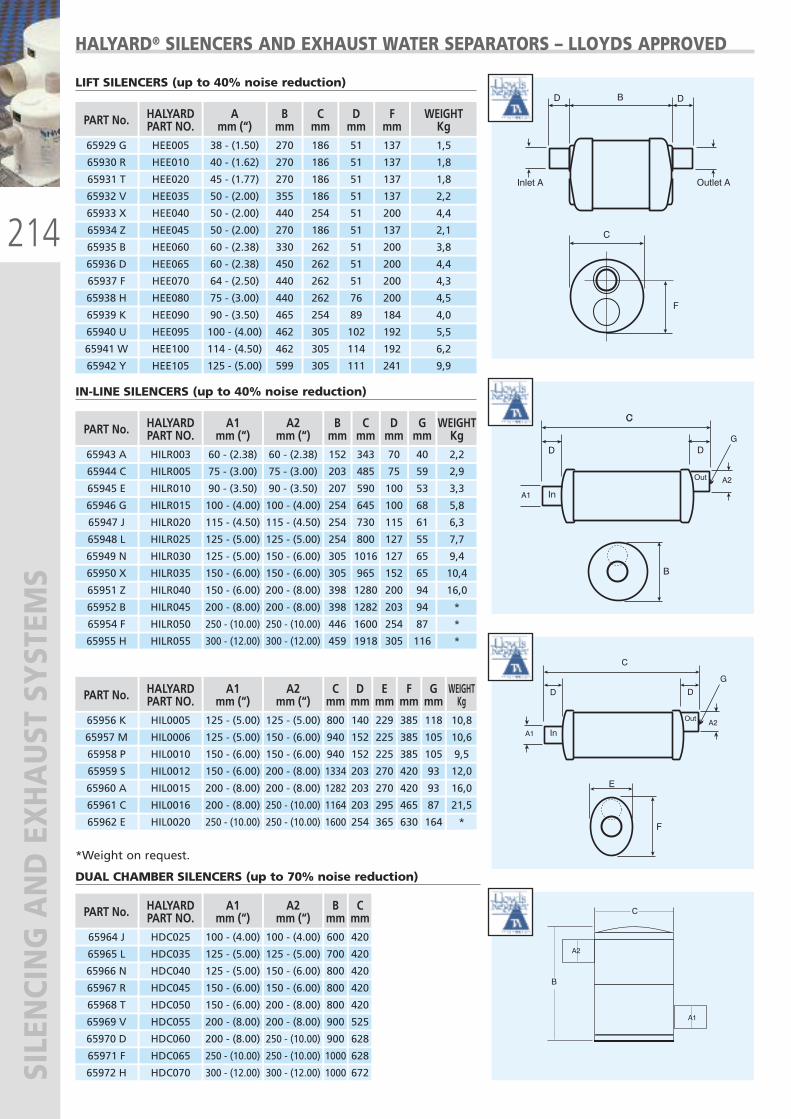
214
SILENCING AND EXHAUST SYSTEM
SHALYARD® SILENCERS AND EXHAUST WATER SEPARATORS – LLOYDS APPROVED
LIFT SILENCERS (up to 40% noise reduction)
IN-LINE SILENCERS (up to 40% noise reduction)
PART No.
65943 A
HALYARDPART NO.HILR003
A1mm (“)60 - (2.38)
A2mm (“)60 - (2.38)
Bmm152
Cmm343
Dmm70
Gmm40
WEIGHTKg2,2
65944 C HILR005 75 - (3.00) 75 - (3.00) 203 485 75 59 2,9
65945 E HILR010 90 - (3.50) 90 - (3.50) 207 590 100 53 3,3
65946 G HILR015 100 - (4.00) 100 - (4.00) 254 645 100 68 5,8
65947 J HILR020 115 - (4.50) 115 - (4.50) 254 730 115 61 6,3
65948 L HILR025 125 - (5.00) 125 - (5.00) 254 800 127 55 7,7
65949 N HILR030 125 - (5.00) 150 - (6.00) 305 1016 127 65 9,4
65950 X HILR035 150 - (6.00) 150 - (6.00) 305 965 152 65 10,4
65951 Z HILR040 150 - (6.00) 200 - (8.00) 398 1280 200 94 16,0
65952 B HILR045 200 - (8.00) 200 - (8.00) 398 1282 203 94 *
65954 F HILR050 250 - (10.00) 250 - (10.00) 446 1600 254 87 *
65955 H HILR055 300 - (12.00) 300 - (12.00) 459 1918 305 116 *
PART No.
65956 K
HALYARDPART NO.HIL0005
A1mm (“)
125 - (5.00)
A2mm (“)
125 - (5.00)
Cmm800
WEIGHTKg10,8
65957 M HIL0006 125 - (5.00) 150 - (6.00) 940 10,6
65958 P HIL0010 150 - (6.00) 150 - (6.00) 940 9,5
Dmm140
152
152
Emm229
225
225
Fmm385
385
385
Gmm118
105
105
65959 S HIL0012 150 - (6.00) 200 - (8.00) 1334 12,0203 270 420 93
65960 A HIL0015 200 - (8.00) 200 - (8.00) 1282 16,0203 270 420 93
65961 C HIL0016 200 - (8.00) 250 - (10.00) 1164 21,5203 295 465 87
65962 E HIL0020 250 - (10.00) 250 - (10.00) 1600 *254 365 630 164
PART No.
65964 J
HALYARDPART NO.HDC025
A1mm (“)
100 - (4.00)
A2mm (“)
100 - (4.00)
Bmm600
65965 L HDC035 125 - (5.00) 125 - (5.00) 700
65966 N HDC040 125 - (5.00) 150 - (6.00) 800
Cmm420
420
420
65967 R HDC045 150 - (6.00) 150 - (6.00) 800 420
65968 T HDC050 150 - (6.00) 200 - (8.00) 800 420
65969 V HDC055 200 - (8.00) 200 - (8.00) 900 525
65970 D HDC060 200 - (8.00) 250 - (10.00) 900 628
65971 F HDC065 250 - (10.00) 250 - (10.00) 1000 628
65972 H HDC070 300 - (12.00) 300 - (12.00) 1000 672
PART No.
65929 G
65930 R
HALYARDPART NO.HEE005
HEE010
Amm (“)38 - (1.50)
40 - (1.62)
Bmm270
270
Cmm186
186
Dmm51
51
Fmm137
137
WEIGHTKg1,5
1,8
65931 T
65932 V
HEE020
HEE035
45 - (1.77)
50 - (2.00)
270
355
186
186
51
51
137
137
1,8
2,2
65933 X
65934 Z
HEE040
HEE045
50 - (2.00)
50 - (2.00)
440
270
254
186
51
51
200
137
4,4
2,1
65935 B
65936 D
HEE060
HEE065
60 - (2.38)
60 - (2.38)
330
450
262
262
51
51
200
200
3,8
4,4
65937 F
65938 H
HEE070
HEE080
64 - (2.50)
75 - (3.00)
440
440
262
262
51
76
200
200
4,3
4,5
65939 K
65940 U
HEE090
HEE095
90 - (3.50)
100 - (4.00)
465
462
254
305
89
102
184
192
4,0
5,5
65942 Y
65941 W
HEE105
HEE100
125 - (5.00)
114 - (4.50)
599
462
305
305
111
114
241
192
9,9
6,2
*Weight on request.
DUAL CHAMBER SILENCERS (up to 70% noise reduction)
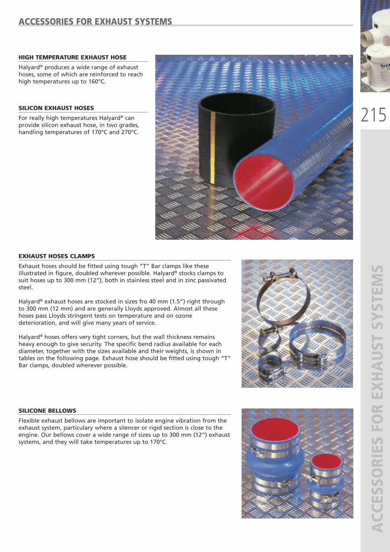
215
ACCESSORIES FOR EXHAUST SYSTEM
S
ACCESSORIES FOR EXHAUST SYSTEMS
HIGH TEMPERATURE EXHAUST HOSE
Halyard® produces a wide range of exhausthoses, some of which are reinforced to reachhigh temperatures up to 160°C.
SILICON EXHAUST HOSES
For really high temperatures Halyard® canprovide silicon exhaust hose, in two grades,handling temperatures of 170°C and 270°C.
EXHAUST HOSES CLAMPS
Exhaust hoses should be fitted using tough “T” Bar clamps like theseillustrated in figure, doubled wherever possible. Halyard® stocks clamps tosuit hoses up to 300 mm (12”), both in stainless steel and in zinc passivatedsteel.
Halyard® exhaust hoses are stocked in sizes fro 40 mm (1.5”) right throughto 300 mm (12 mm) and are generally Lloyds approved. Almost all thesehoses pass Lloyds stringent tests on temperature and on ozonedeterioration, and will give many years of service.
Halyard® hoses offers very tight corners, but the wall thickness remainsheavy enough to give security. The specific bend radius available for eachdiameter, together with the sizes available and their weights, is shown intables on the following page. Exhaust hose should be fitted using tough “T”Bar clamps, doubled wherever possible.
SILICONE BELLOWS
Flexible exhaust bellows are important to isolate engine vibration from theexhaust system, particulary where a silencer or rigid section is close to theengine. Our bellows cover a wide range of sizes up to 300 mm (12”) exhaustsystems, and they will take temperatures up to 170°C.
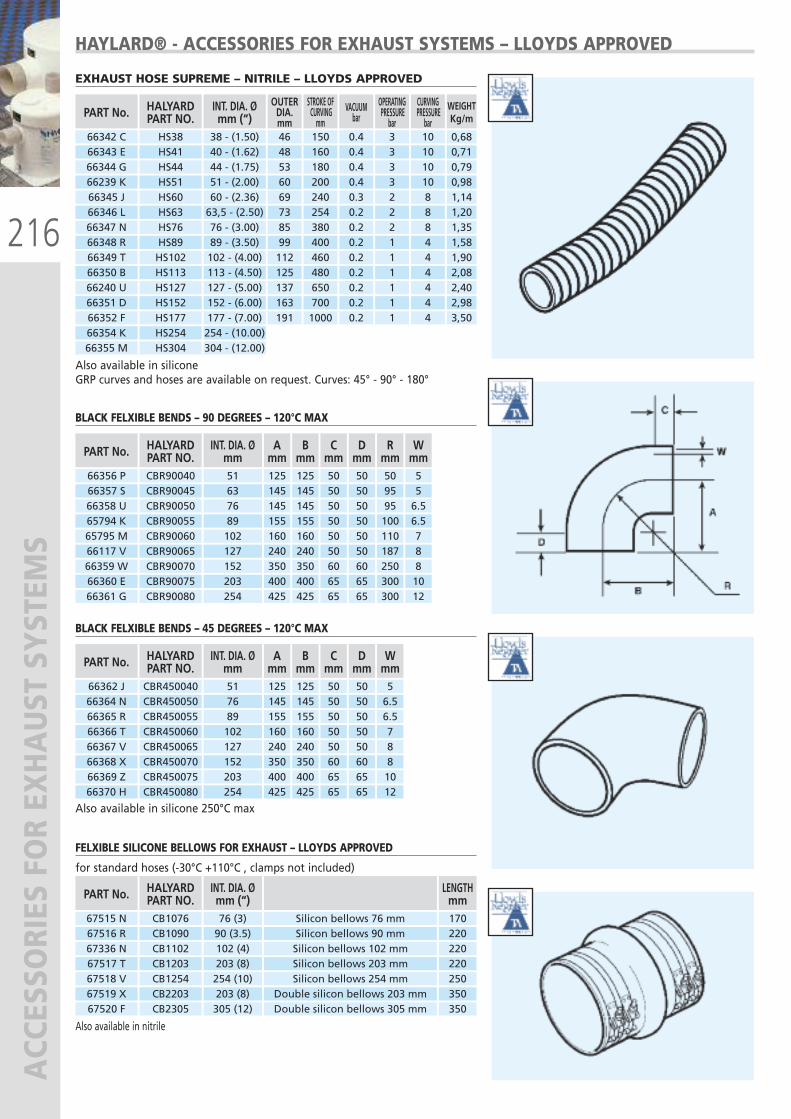
216
ACCESSORIES FOR EXHAUST SYSTEM
SHAYLARD® - ACCESSORIES FOR EXHAUST SYSTEMS – LLOYDS APPROVED
EXHAUST HOSE SUPREME – NITRILE – LLOYDS APPROVED
BLACK FELXIBLE BENDS – 90 DEGREES – 120°C MAX
PART No.
66356 P
HALYARDPART NO.CBR90040
INT. DIA. Ømm51
Bmm125
Cmm50
Dmm50
Wmm5
66357 S CBR90045 63 145 50 50 566358 U CBR90050 76 145 50 50 6.5
Amm125145145
Rmm509595
65794 K CBR90055 89 155 50 50 6.5155 10065795 M CBR90060 102 160 50 50 7160 11066117 V CBR90065 127 240 50 50 8240 18766359 W CBR90070 152 350 60 60 8350 25066360 E CBR90075 203 400 65 65 10400 30066361 G CBR90080 254 425 65 65 12425 300
BLACK FELXIBLE BENDS – 45 DEGREES – 120°C MAX
PART No.
66362 J
HALYARDPART NO.CBR450040
INT. DIA. Ømm51
Bmm125
Cmm50
Dmm50
Wmm5
66364 N CBR450050 76 145 50 50 6.5
Amm125145
66365 R CBR450055 89 155 50 50 6.515566366 T CBR450060 102 160 50 50 716066367 V CBR450065 127 240 50 50 824066368 X CBR450070 152 350 60 60 835066369 Z CBR450075 203 400 65 65 1040066370 H CBR450080 254 425 65 65 12425
PART No.
66342 C66343 E
HALYARDPART NO.HS38HS41
INT. DIA. Ømm (“)38 - (1.50)40 - (1.62)
OUTERDIA.mm4648
STROKE OFCURVING
mm150160
VACUUMbar
0.40.4
OPERATINGPRESSURE
bar33
WEIGHTKg/m
0,680,71
66344 G66239 K
HS44HS51
44 - (1.75)51 - (2.00)
5360
180200
0.40.4
33
0,790,98
66345 J66346 L
HS60HS63
60 - (2.36)63,5 - (2.50)
6973
240254
0.30.2
22
1,141,20
66347 N66348 R
HS76HS89
76 - (3.00)89 - (3.50)
8599
380400
0.20.2
21
1,351,58
66349 T66350 B
HS102HS113
102 - (4.00)113 - (4.50)
112125
460480
0.20.2
11
1,902,08
66240 U66351 D
HS127HS152
127 - (5.00)152 - (6.00)
137163
650700
0.20.2
11
2,402,98
66352 F HS17766354 K HS254 254 - (10.00)66355 M HS304 304 - (12.00)
177 - (7.00) 191 1000 0.2 1
CURVINGPRESSURE
bar10101010888444444 3,50
Also available in siliconeGRP curves and hoses are available on request. Curves: 45° - 90° - 180°
Also available in silicone 250°C max
Also available in nitrile
FELXIBLE SILICONE BELLOWS FOR EXHAUST – LLOYDS APPROVED
for standard hoses (-30°C +110°C , clamps not included)
PART No.
67515 N
HALYARDPART NO.CB1076
INT. DIA. Ømm (“)76 (3)
LENGTHmm170
67516 R CB1090 90 (3.5) 22067336 N CB1102 102 (4) 220
Silicon bellows 76 mmSilicon bellows 90 mmSilicon bellows 102 mm
67517 T CB1203 203 (8) 220Silicon bellows 203 mm67518 V CB1254 254 (10) 250Silicon bellows 254 mm67519 X CB2203 203 (8) 350Double silicon bellows 203 mm67520 F CB2305 305 (12) 350Double silicon bellows 305 mm
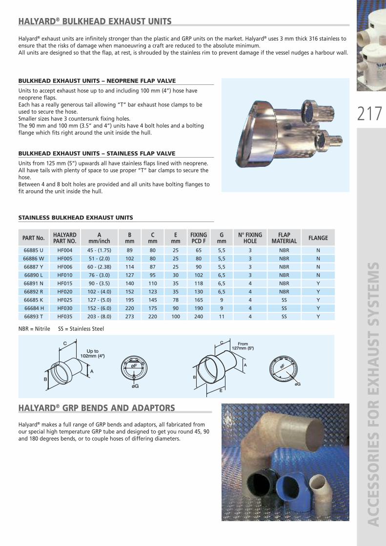
217
ACCESSORIES FOR EXHAUST SYSTEM
SøøGG
øøFFAA
BB
CC
Up to102mm (4")
Up to102mm (4")
øøFF
øøGG
AA
BB
EE
From127mm (5")
From127mm (5")
CC
HALYARD® BULKHEAD EXHAUST UNITS
BULKHEAD EXHAUST UNITS – NEOPRENE FLAP VALVE
Units to accept exhaust hose up to and including 100 mm (4”) hose haveneoprene flaps. Each has a really generous tail allowing “T” bar exhaust hose clamps to beused to secure the hose.Smaller sizes have 3 countersunk fixing holes.The 90 mm and 100 mm (3.5” and 4”) units have 4 bolt holes and a boltingflange which fits right around the unit inside the hull.
BULKHEAD EXHAUST UNITS – STAINLESS FLAP VALVE
Units from 125 mm (5”) upwards all have stainless flaps lined with neoprene.All have tails with plenty of space to use proper “T” bar clamps to secure thehose.Between 4 and 8 bolt holes are provided and all units have bolting flanges tofit around the unit inside the hull.
STAINLESS BULKHEAD EXHAUST UNITS
PART No.
66885 U
66886 W
HALYARDPART NO.HF004
HF005
Amm/inch45 - (1.75)
51 - (2.0)
Bmm89
102
Cmm80
80
Emm25
25
FIXINGPCD F65
80
Gmm5,5
5,5
N° FIXINGHOLE3
3
FLAPMATERIAL
NBR
NBR
FLANGE
N
N
66887 Y
66890 L
HF006
HF010
60 - (2.38)
76 - (3.0)
114
127
87
95
25
30
90
102
5,5
6,5
3
3
NBR
NBR
N
N
66891 N
66892 R
HF015
HF020
90 - (3.5)
102 - (4.0)
140
152
110
123
35
35
118
130
6,5
6,5
4
4
NBR
NBR
Y
Y
66685 K
66684 H
HF025
HF030
127 - (5.0)
152 - (6.0)
195
220
145
175
78
90
165
190
9
9
4
4
SS
SS
Y
Y
66893 T HF035 203 - (8.0) 273 220 100 240 11 4 SS Y
HALYARD® GRP BENDS AND ADAPTORS
Halyard® makes a full range of GRP bends and adaptors, all fabricated fromour special high temperature GRP tube and designed to get you round 45, 90and 180 degrees bends, or to couple hoses of differing diameters.
NBR = Nitrile SS = Stainless Steel
Halyard® exhaust units are infinitely stronger than the plastic and GRP units on the market. Halyard® uses 3 mm thick 316 stainless toensure that the risks of damage when manoeuvring a craft are reduced to the absolute minimum.All units are designed so that the flap, at rest, is shrouded by the stainless rim to prevent damage if the vessel nudges a harbour wall.
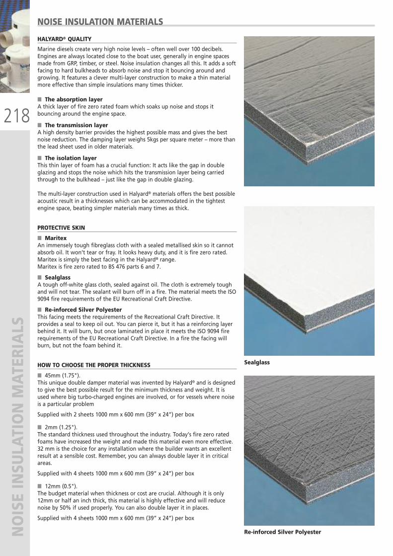
218
NOISE INSULATION MATERIALS
NOISE INSULATION MATERIALS
HALYARD® QUALITY
Marine diesels create very high noise levels – often well over 100 decibels.Engines are always located close to the boat user, generally in engine spacesmade from GRP, timber, or steel. Noise insulation changes all this. It adds a softfacing to hard bulkheads to absorb noise and stop it bouncing around andgrowing. It features a clever multi-layer construction to make a thin materialmore effective than simple insulations many times thicker.
� The absorption layerA thick layer of fire zero rated foam which soaks up noise and stops itbouncing around the engine space.
� The transmission layerA high density barrier provides the highest possible mass and gives the bestnoise reduction. The damping layer weighs 5kgs per square meter – more thanthe lead sheet used in older materials.
� The isolation layerThis thin layer of foam has a crucial function: It acts like the gap in doubleglazing and stops the noise which hits the transmission layer being carriedthrough to the bulkhead – just like the gap in double glazing.
The multi-layer construction used in Halyard® materials offers the best possibleacoustic result in a thicknesses which can be accommodated in the tightestengine space, beating simpler materials many times as thick.
PROTECTIVE SKIN
� MaritexAn immensely tough fibreglass cloth with a sealed metallised skin so it cannotabsorb oil. It won’t tear or fray. It looks heavy duty, and it is fire zero rated.Maritex is simply the best facing in the Halyard® range.Maritex is fire zero rated to BS 476 parts 6 and 7.
� SealglassA tough off-white glass cloth, sealed against oil. The cloth is extremely toughand will not tear. The sealant will burn off in a fire. The material meets the ISO9094 fire requirements of the EU Recreational Craft Directive.
� Re-inforced Silver PolyesterThis facing meets the requirements of the Recreational Craft Directive. Itprovides a seal to keep oil out. You can pierce it, but it has a reinforcing layerbehind it. It will burn, but once laminated in place it meets the ISO 9094 firerequirements of the EU Recreational Craft Directive. In a fire the facing willburn, but not the foam behind it.
HOW TO CHOOSE THE PROPER THICKNESS
� 45mm (1.75").This unique double damper material was invented by Halyard® and is designedto give the best possible result for the minimum thickness and weight. It isused where big turbo-charged engines are involved, or for vessels where noiseis a particular problem
Supplied with 2 sheets 1000 mm x 600 mm (39” x 24”) per box
� 2mm (1.25"). The standard thickness used throughout the industry. Today’s fire zero ratedfoams have increased the weight and made this material even more effective.32 mm is the choice for any installation where the builder wants an excellentresult at a sensible cost. Remember, you can always double layer it in criticalareas.
Supplied with 4 sheets 1000 mm x 600 mm (39” x 24”) per box
� 12mm (0.5"). The budget material when thickness or cost are crucial. Although it is only12mm or half an inch thick, this material is highly effective and will reducenoise by 50% if used properly. You can also double layer it in places.
Supplied with 4 sheets 1000 mm x 600 mm (39” x 24”) per box
Sealglass
Re-inforced Silver Polyester
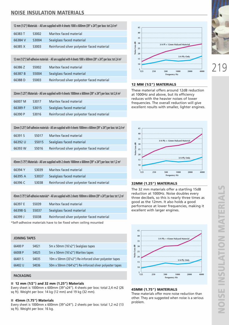
219
NOISE INSULATION MATERIALS
15
10
5125 250 500 1000 2000 4000
Frequency Hz
3/4 Ply + 45mm Halyard Material
3/4 Ply Only
45
40
35
30
25
20
15
10
5125 250 500 1000 2000 4000
Noi
se L
oss
dB
Frequency Hz
3/4 Pl + 12mm Halyard Material
3/4 Ply Only
45
40
35
30
25
20
15
10
5125 250 500 1000 2000 4000
Noi
se L
oss
dBFrequency Hz
3/4 Ply + 32mm Halyard Material
3/4 Ply Only
45
40
35
30
25
20Noi
se L
oss
dB
15
10
5125 250 500 1000 2000 4000
Frequency Hz
3/4 Ply + 45mm Halyard Material
3/4 Ply Only
45
40
35
30
25
20
15
10
5125 250 500 1000 2000 4000
Noi
se L
oss
dB
Frequency Hz
3/4 Pl + 12mm Halyard Material
3/4 Ply Only
45
40
35
30
25
20
15
10
5125 250 500 1000 2000 4000
Noi
se L
oss
dB
Frequency Hz
3/4 Ply + 32mm Halyard Material
3/4 Ply Only
45
40
35
30
25
20Noi
se L
oss
dB
NOISE INSULATION MATERIALS
12 mm (1/2") Materials - All are supplied with 4 sheets 1000 x 600mm (39" x 24") per box: tot 2,4 m2
66383 T S3002 Maritex faced material
66384 V S3004 Sealglass faced material
66385 X S3003 Reinforced silver polyester faced material
12 mm (1/2") Self-adhesive materials - All are supplied with 4 sheets 1000 x 600mm (39" x 24") per box: tot 2,4 m2
66386 Z S5002 Maritex faced material
66387 B S5004 Sealglass faced material
66388 D S5003 Reinforced silver polyester faced material
32mm (1.25") Materials - All are supplied with 4 sheets 1000mm x 600mm (39" x 24") per box: tot 2,4 m2
66007 M S3017 Maritex faced material
66389 F S3015 Sealglass faced material
66390 P S3016 Reinforced silver polyester faced material
32mm (1.25") Self-adhesive materials - All are supplied with 4 sheets 1000mm x 600mm (39" x 24") per box: tot 2,4 m2
66391 S S5017 Maritex faced material
66392 U S5015 Sealglass faced material
66393 W S5016 Reinforced silver polyester faced material
45mm (1.75") Materials - All are supplied with 2 sheets 1000mm x 600mm (39" x 24") per box: tot 1,2 m2
66394 Y S3039 Maritex faced material
66395 A S3037 Sealglass faced material
66396 C S3038 Reinforced silver polyester faced material
45mm (1.75") Self-adhesive materials* - All are supplied with 2 sheets 1000mm x 600mm (39" x 24") per box: tot 1,2 m2
66397 E S5039 Maritex faced material
66398 G S5037 Sealglass faced material
66399 J S5038 Reinforced silver polyester faced material
*Self-adhesive materials have to be fixed when ceiling mounted
JOINING TAPES
66400 P S4021 5m x 50mm (16’x2”) Sealglass tapes
66008 P S4025 5m x 50mm (16’x2”) Maritex tapes
66401 S S4035 10m x 50mm (33’x2”) Re-inforced silver polyester tapes
66402 U S4036 50m x 50mm (164’x2”) Re-inforced silver polyester tapes
PACKAGING
� 12 mm (1/2") and 32 mm (1.25”) MaterialsEvery sheet is 1000mm x 600mm (39”x24”). 4 sheets per box: total 2,4 m2 (26sq ft). Weight per box: 14 kg (12 mm) and 19 kg (32 mm).
� 45mm (1.75") MaterialsEvery sheet is 1000mm x 600mm (39”x24”). 2 sheets per box: total 1,2 m2 (13sq ft). Weight per box: 16 kg.
12 MM (1/2") MATERIALS
These material offers around 12dB reductionat 1000Hz and above, but its efficiencyreduces with the heavier noises of lowerfrequencies. The overall reduction will giveexcellent results with smaller, lighter engines.
32MM (1.25") MATERIALS
The 32 mm materials offer a startling 15dBreduction at 1000Hz. Noise doubles everythree decibels, so this is nearly three times asgood as the 12mm. It also holds a goodperformance at lower frequencies, making itexcellent with larger engines.
45MM (1.75") MATERIALS These materials offer more noise reduction thanother. They are suggested when noise is a seriousproblem.
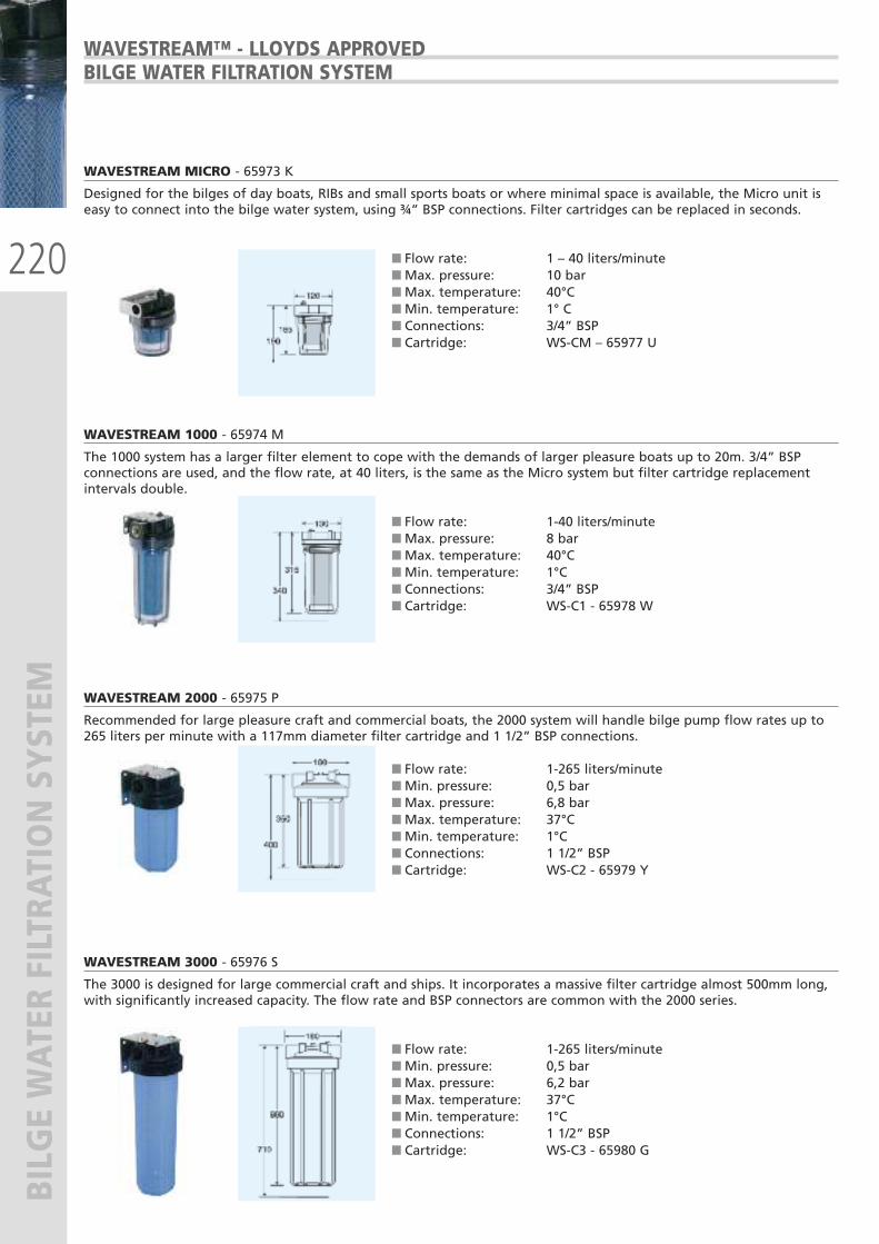
220
BILGE WATER FILTRATION SYSTEM
WAVESTREAM™ - LLOYDS APPROVEDBILGE WATER FILTRATION SYSTEM
WAVESTREAM MICRO - 65973 K
Designed for the bilges of day boats, RIBs and small sports boats or where minimal space is available, the Micro unit iseasy to connect into the bilge water system, using ¾” BSP connections. Filter cartridges can be replaced in seconds.
� Flow rate: 1 – 40 liters/minute � Max. pressure: 10 bar � Max. temperature: 40°C � Min. temperature: 1° C � Connections: 3/4” BSP � Cartridge: WS-CM – 65977 U
WAVESTREAM 1000 - 65974 M
The 1000 system has a larger filter element to cope with the demands of larger pleasure boats up to 20m. 3/4” BSPconnections are used, and the flow rate, at 40 liters, is the same as the Micro system but filter cartridge replacementintervals double.
� Flow rate: 1-40 liters/minute � Max. pressure: 8 bar � Max. temperature: 40°C � Min. temperature: 1°C � Connections: 3/4” BSP � Cartridge: WS-C1 - 65978 W
WAVESTREAM 2000 - 65975 P
Recommended for large pleasure craft and commercial boats, the 2000 system will handle bilge pump flow rates up to265 liters per minute with a 117mm diameter filter cartridge and 1 1/2” BSP connections.
� Flow rate: 1-265 liters/minute � Min. pressure: 0,5 bar � Max. pressure: 6,8 bar � Max. temperature: 37°C � Min. temperature: 1°C � Connections: 1 1/2” BSP � Cartridge: WS-C2 - 65979 Y
WAVESTREAM 3000 - 65976 S
The 3000 is designed for large commercial craft and ships. It incorporates a massive filter cartridge almost 500mm long,with significantly increased capacity. The flow rate and BSP connectors are common with the 2000 series.
� Flow rate: 1-265 liters/minute � Min. pressure: 0,5 bar � Max. pressure: 6,2 bar � Max. temperature: 37°C � Min. temperature: 1°C � Connections: 1 1/2” BSP � Cartridge: WS-C3 - 65980 G
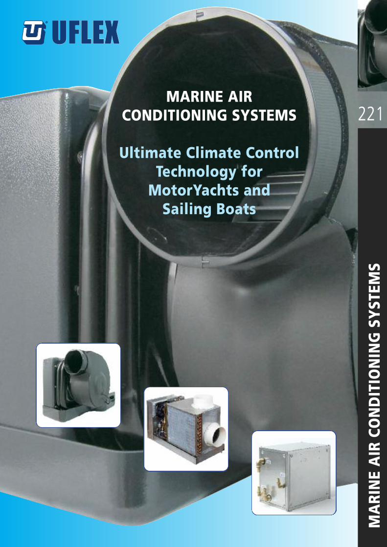
221
MARINE AIR CONDITIONING SYSTEM
S
A world of marine equipment
®®
MARINE AIR CONDITIONING SYSTEMS
Ultimate Climate ControlTechnology for MotorYachts and Sailing Boats
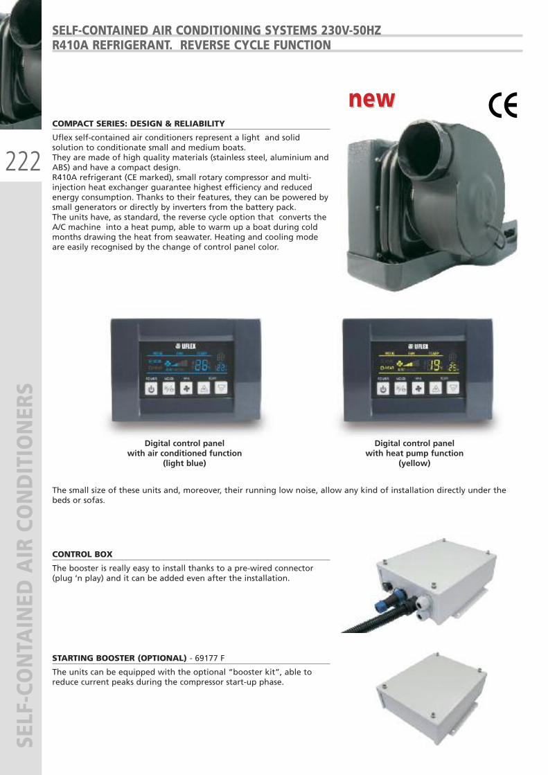
222
SELF-CONTA
INED
AIR CONDITIONER
SSELF-CONTAINED AIR CONDITIONING SYSTEMS 230V-50HZR410A REFRIGERANT. REVERSE CYCLE FUNCTION
COMPACT SERIES: DESIGN & RELIABILITY
Uflex self-contained air conditioners represent a light and solidsolution to conditionate small and medium boats.They are made of high quality materials (stainless steel, aluminium andABS) and have a compact design.R410A refrigerant (CE marked), small rotary compressor and multi-injection heat exchanger guarantee highest efficiency and reducedenergy consumption. Thanks to their features, they can be powered bysmall generators or directly by inverters from the battery pack.The units have, as standard, the reverse cycle option that converts theA/C machine into a heat pump, able to warm up a boat during coldmonths drawing the heat from seawater. Heating and cooling modeare easily recognised by the change of control panel color.
CONTROL BOX
The booster is really easy to install thanks to a pre-wired connector(plug ‘n play) and it can be added even after the installation.
STARTING BOOSTER (OPTIONAL) - 69177 F
The units can be equipped with the optional “booster kit”, able toreduce current peaks during the compressor start-up phase.
The small size of these units and, moreover, their running low noise, allow any kind of installation directly under thebeds or sofas.
new new
Digital control panelwith air conditioned function
(light blue)
Digital control panel with heat pump function
(yellow)
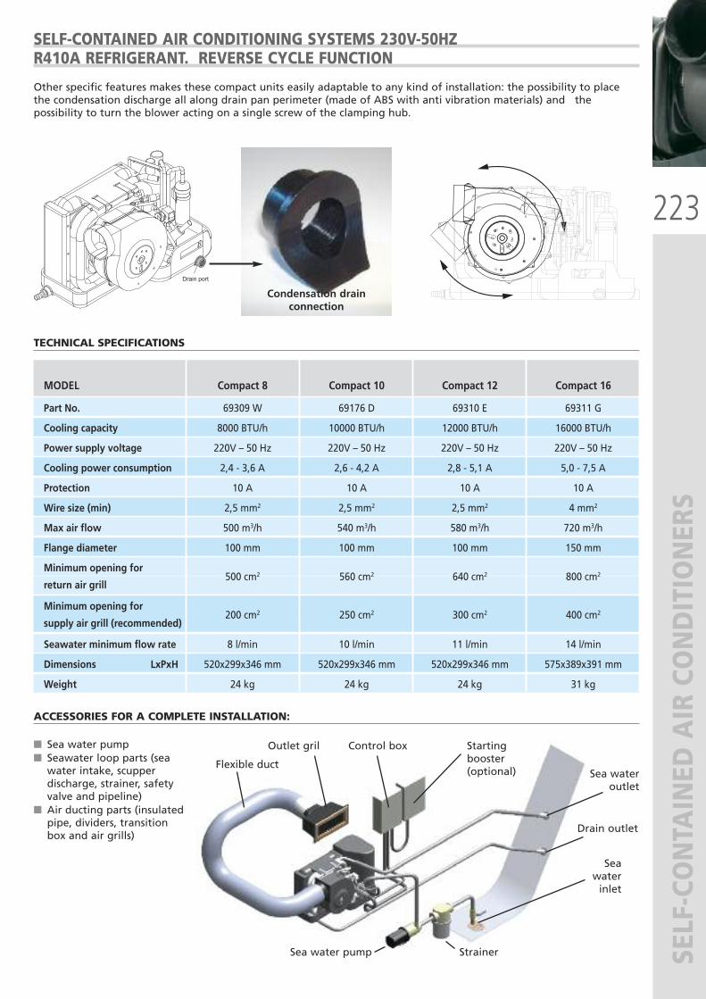
223
SELF-CONTA
INED
AIR CONDITIONER
S
Drain port
SELF-CONTAINED AIR CONDITIONING SYSTEMS 230V-50HZR410A REFRIGERANT. REVERSE CYCLE FUNCTION
Other specific features makes these compact units easily adaptable to any kind of installation: the possibility to placethe condensation discharge all along drain pan perimeter (made of ABS with anti vibration materials) and thepossibility to turn the blower acting on a single screw of the clamping hub.
Condensation drainconnection
ACCESSORIES FOR A COMPLETE INSTALLATION:
� Sea water pump� Seawater loop parts (seawater intake, scupperdischarge, strainer, safetyvalve and pipeline)
� Air ducting parts (insulatedpipe, dividers, transitionbox and air grills)
Flexible duct
Outlet gril
Sea wateroutlet
MODEL Compact 8 Compact 10 Compact 12 Compact 16
Part No. 69309 W 69176 D 69310 E 69311 G
Cooling capacity 8000 BTU/h 10000 BTU/h 12000 BTU/h 16000 BTU/h
Power supply voltage 220V – 50 Hz 220V – 50 Hz 220V – 50 Hz 220V – 50 Hz
Cooling power consumption 2,4 - 3,6 A 2,6 - 4,2 A 2,8 - 5,1 A 5,0 - 7,5 A
Protection 10 A 10 A 10 A 10 A
Wire size (min) 2,5 mm2 2,5 mm2 2,5 mm2 4 mm2
Max air flow 500 m3/h 540 m3/h 580 m3/h 720 m3/h
Flange diameter 100 mm 100 mm 100 mm 150 mm
Minimum opening for
return air grill 500 cm2 560 cm2 640 cm2 800 cm2
Minimum opening for
supply air grill (recommended) 200 cm2 250 cm2 300 cm2 400 cm2
Seawater minimum flow rate 8 l/min 10 l/min 11 l/min 14 l/min
Dimensions LxPxH 520x299x346 mm 520x299x346 mm 520x299x346 mm 575x389x391 mm
Weight 24 kg 24 kg 24 kg 31 kg
Control box Startingbooster(optional)
Drain outlet
Sea water inlet
StrainerSea water pump
TECHNICAL SPECIFICATIONS
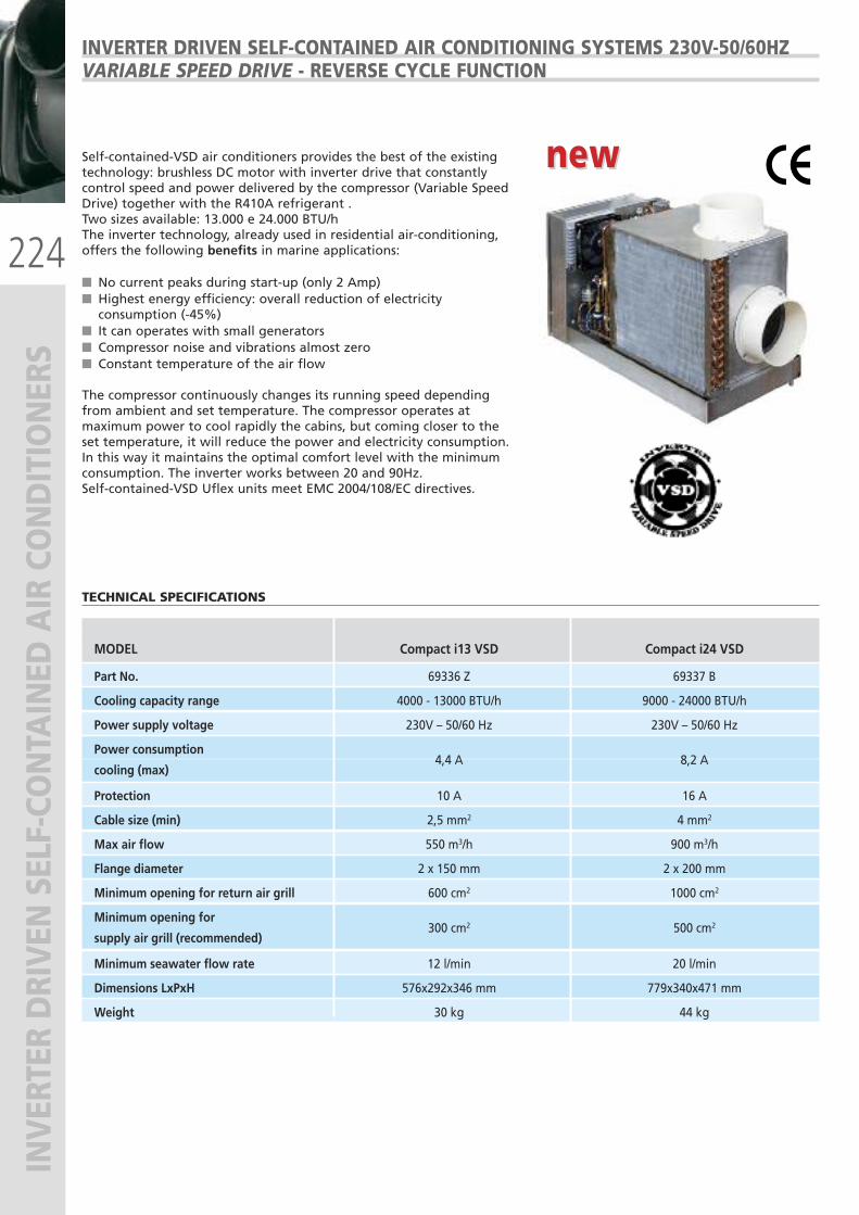
224
INVER
TER DRIVEN
SELF-CO
NTA
INED
AIR CONDITIONER
S INVERTER DRIVEN SELF-CONTAINED AIR CONDITIONING SYSTEMS 230V-50/60HZ VARIABLE SPEED DRIVE - REVERSE CYCLE FUNCTION
Self-contained-VSD air conditioners provides the best of the existingtechnology: brushless DC motor with inverter drive that constantlycontrol speed and power delivered by the compressor (Variable SpeedDrive) together with the R410A refrigerant .Two sizes available: 13.000 e 24.000 BTU/hThe inverter technology, already used in residential air-conditioning,offers the following benefits in marine applications:
� No current peaks during start-up (only 2 Amp)� Highest energy efficiency: overall reduction of electricityconsumption (-45%)
� It can operates with small generators� Compressor noise and vibrations almost zero� Constant temperature of the air flow
The compressor continuously changes its running speed dependingfrom ambient and set temperature. The compressor operates atmaximum power to cool rapidly the cabins, but coming closer to theset temperature, it will reduce the power and electricity consumption.In this way it maintains the optimal comfort level with the minimumconsumption. The inverter works between 20 and 90Hz.Self-contained-VSD Uflex units meet EMC 2004/108/EC directives.
new new
MODEL Compact i13 VSD Compact i24 VSD
Part No. 69336 Z 69337 B
Cooling capacity range 4000 - 13000 BTU/h 9000 - 24000 BTU/h
Power supply voltage 230V – 50/60 Hz 230V – 50/60 Hz
Power consumption
cooling (max) 4,4 A 8,2 A
Protection 10 A 16 A
Cable size (min) 2,5 mm2 4 mm2
Max air flow 550 m3/h 900 m3/h
Flange diameter 2 x 150 mm 2 x 200 mm
Minimum opening for return air grill 600 cm2 1000 cm2
Minimum opening for
supply air grill (recommended) 300 cm2 500 cm2
Minimum seawater flow rate 12 l/min 20 l/min
Dimensions LxPxH 576x292x346 mm 779x340x471 mm
Weight 30 kg 44 kg
TECHNICAL SPECIFICATIONS
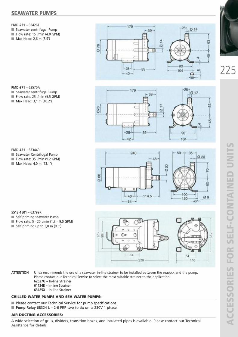
225
ACC
ESSO
RIES
FOR SE
LF-CONTA
INED
UNITS
SEAWATER PUMPS
PMD-221 – 63426T � Seawater centrifugal Pump� Flow rate: 15 l/min (4.0 GPM)� Max Head: 2,6 m (8.5’)
PMD-371 – 63570A � Seawater centrifugal Pump� Flow rate: 25 l/min (5.5 GPM)� Max Head: 3,1 m (10.2’)
PMD-421 – 63344R � Seawater Centrifugal Pump� Flow rate: 35 l/min (9.2 GPM)� Max Head: 4,0 m (13.1’)
5513-1E01 – 63799K� Self priming seawater Pump� Flow rate: 5 - 20 l/min (1.3 – 9.0 GPM)� Self priming up to 3,0 m (9.8’)
ATTENTION Uflex recommends the use of a seawater in-line strainer to be installed between the seacock and the pump. Please contact our Technical Service to select the most suitable strainer to the application 62527U – In-line Strainer 61124E – In-line Strainer 63185X – In-line Strainer
CHILLED WATER PUMPS AND SEA WATER PUMPS:
� Please contact our Technical Service for pump specifications� Pump Relay 68324 L – 2-6 PRP two to six units 230V 1 phase
AIR DUCTING ACCESSORIES:
A wide selection of grills, dividers, transition boxes, and insulated pipes is available. Please contact our TechnicalAssistance for details.
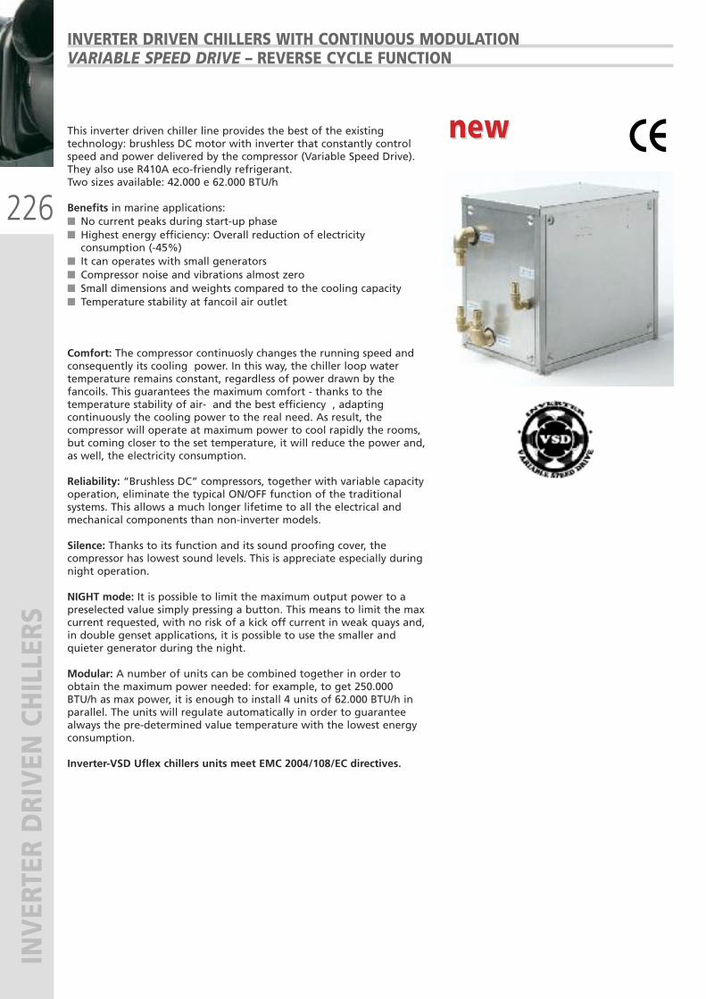
226
INVER
TER DRIVEN
CHILLERS
INVERTER DRIVEN CHILLERS WITH CONTINUOUS MODULATION VARIABLE SPEED DRIVE – REVERSE CYCLE FUNCTION
This inverter driven chiller line provides the best of the existingtechnology: brushless DC motor with inverter that constantly controlspeed and power delivered by the compressor (Variable Speed Drive).They also use R410A eco-friendly refrigerant.Two sizes available: 42.000 e 62.000 BTU/h
Benefits in marine applications: � No current peaks during start-up phase� Highest energy efficiency: Overall reduction of electricityconsumption (-45%)
� It can operates with small generators� Compressor noise and vibrations almost zero� Small dimensions and weights compared to the cooling capacity� Temperature stability at fancoil air outlet
Comfort: The compressor continuosly changes the running speed andconsequently its cooling power. In this way, the chiller loop watertemperature remains constant, regardless of power drawn by thefancoils. This guarantees the maximum comfort - thanks to thetemperature stability of air- and the best efficiency , adaptingcontinuously the cooling power to the real need. As result, thecompressor will operate at maximum power to cool rapidly the rooms,but coming closer to the set temperature, it will reduce the power and,as well, the electricity consumption.
Reliability: “Brushless DC” compressors, together with variable capacityoperation, eliminate the typical ON/OFF function of the traditionalsystems. This allows a much longer lifetime to all the electrical andmechanical components than non-inverter models.
Silence: Thanks to its function and its sound proofing cover, thecompressor has lowest sound levels. This is appreciate especially duringnight operation.
NIGHT mode: It is possible to limit the maximum output power to apreselected value simply pressing a button. This means to limit the maxcurrent requested, with no risk of a kick off current in weak quays and,in double genset applications, it is possible to use the smaller andquieter generator during the night.
Modular: A number of units can be combined together in order toobtain the maximum power needed: for example, to get 250.000BTU/h as max power, it is enough to install 4 units of 62.000 BTU/h inparallel. The units will regulate automatically in order to guaranteealways the pre-determined value temperature with the lowest energyconsumption.
Inverter-VSD Uflex chillers units meet EMC 2004/108/EC directives.
new new
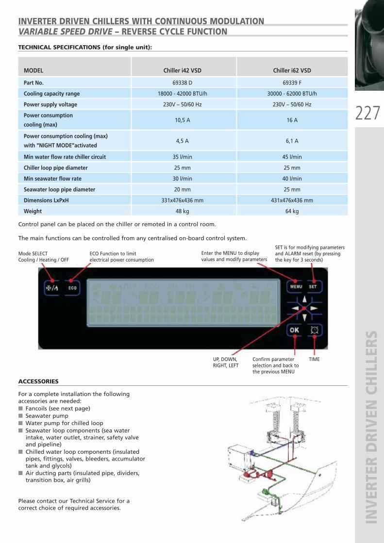
227
INVER
TER DRIVEN
CHILLERS
INVERTER DRIVEN CHILLERS WITH CONTINUOUS MODULATION VARIABLE SPEED DRIVE – REVERSE CYCLE FUNCTION
MODEL Chiller i42 VSD Chiller i62 VSD
Part No. 69338 D 69339 F
Cooling capacity range 18000 - 42000 BTU/h 30000 - 62000 BTU/h
Power supply voltage 230V – 50/60 Hz 230V – 50/60 Hz
Power consumption
cooling (max) 10,5 A 16 A
Power consumption cooling (max)
with “NIGHT MODE”activated 4,5 A 6,1 A
Min water flow rate chiller circuit 35 l/min 45 l/min
Chiller loop pipe diameter 25 mm 25 mm
Min seawater flow rate 30 l/min 40 l/min
Seawater loop pipe diameter 20 mm 25 mm
Dimensions LxPxH 331x476x436 mm 431x476x436 mm
Weight 48 kg 64 kg
TECHNICAL SPECIFICATIONS (for single unit):
Control panel can be placed on the chiller or remoted in a control room.
The main functions can be controlled from any centralised on-board control system.
Mode SELECTCooling / Heating / OFF
ECO Function to limit electrical power consumption
Enter the MENU to displayvalues and modify parameters
SET is for modifying parametersand ALARM reset (by pressingthe key for 3 seconds)
UP, DOWN, RIGHT, LEFT
Confirm parameterselection and back to the previous MENU
TIME
ACCESSORIES
For a complete installation the followingaccessories are needed: � Fancoils (see next page)� Seawater pump� Water pump for chilled loop � Seawater loop components (sea waterintake, water outlet, strainer, safety valveand pipeline)
� Chilled water loop components (insulatedpipes, fittings, valves, bleeders, accumulatortank and glycols)
� Air ducting parts (insulated pipe, dividers,transition box, air grills)
Please contact our Technical Service for acorrect choice of required accessories.
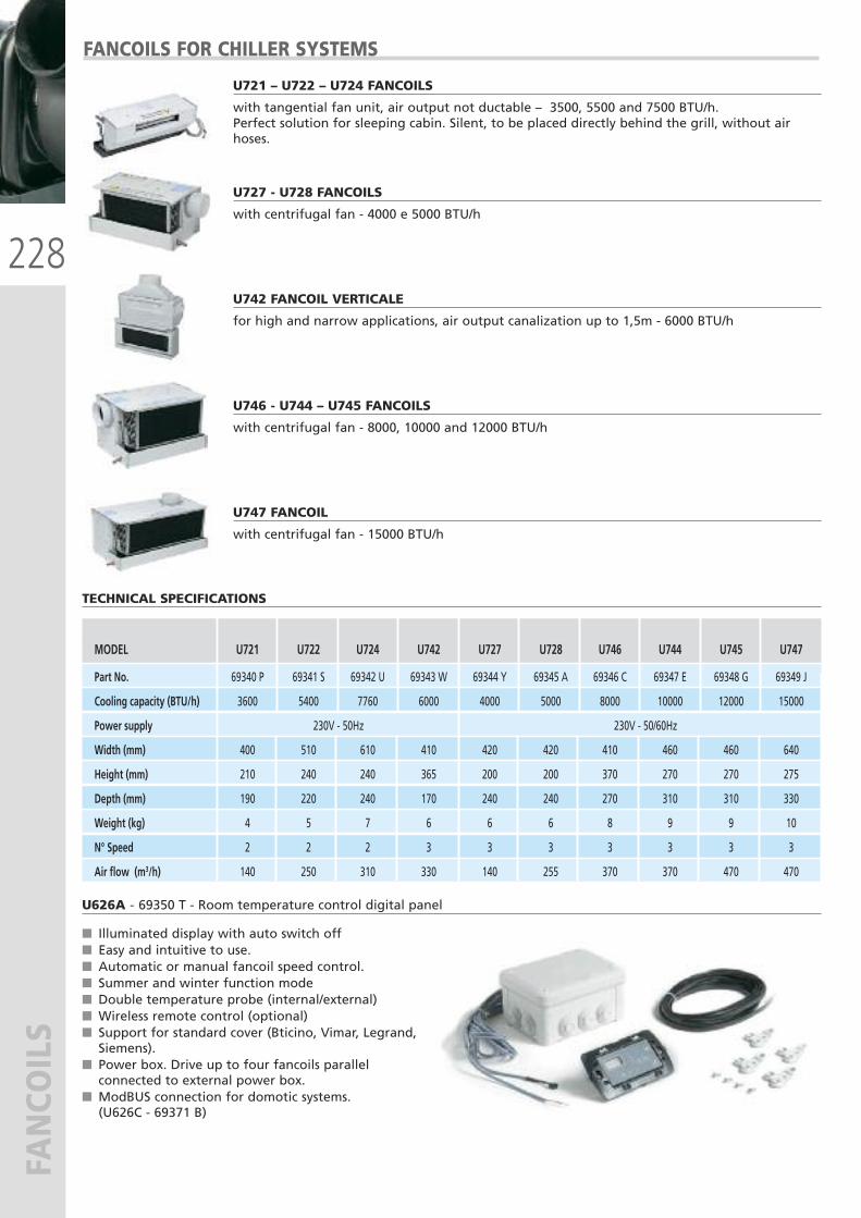
228
FAN
COIL
SFANCOILS FOR CHILLER SYSTEMS
U721 – U722 – U724 FANCOILS
with tangential fan unit, air output not ductable – 3500, 5500 and 7500 BTU/h. Perfect solution for sleeping cabin. Silent, to be placed directly behind the grill, without airhoses.
U727 - U728 FANCOILS
with centrifugal fan - 4000 e 5000 BTU/h
U742 FANCOIL VERTICALE
for high and narrow applications, air output canalization up to 1,5m - 6000 BTU/h
U746 - U744 – U745 FANCOILS
with centrifugal fan - 8000, 10000 and 12000 BTU/h
U747 FANCOIL
with centrifugal fan - 15000 BTU/h
MODEL U721 U722 U724 U742 U727 U728 U746 U744 U745 U747
Part No. 69340 P 69341 S 69342 U 69343 W 69344 Y 69345 A 69346 C 69347 E 69348 G 69349 J
Cooling capacity (BTU/h) 3600 5400 7760 6000 4000 5000 8000 10000 12000 15000
Power supply 230V - 50Hz 230V - 50/60Hz
Width (mm) 400 510 610 410 420 420 410 460 460 640
Height (mm) 210 240 240 365 200 200 370 270 270 275
Depth (mm) 190 220 240 170 240 240 270 310 310 330
Weight (kg) 4 5 7 6 6 6 8 9 9 10
N° Speed 2 2 2 3 3 3 3 3 3 3
Air flow (m3/h) 140 250 310 330 140 255 370 370 470 470
TECHNICAL SPECIFICATIONS
U626A - 69350 T - Room temperature control digital panel
� Illuminated display with auto switch off� Easy and intuitive to use.� Automatic or manual fancoil speed control. � Summer and winter function mode� Double temperature probe (internal/external)� Wireless remote control (optional)� Support for standard cover (Bticino, Vimar, Legrand,Siemens).
� Power box. Drive up to four fancoils parallelconnected to external power box.
� ModBUS connection for domotic systems. (U626C - 69371 B)
229
HEA
TERS
, STO
VES
AND OVEN
S
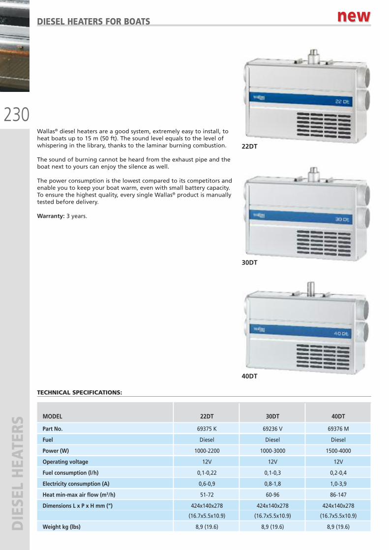
230
DIESE
L HEA
TERS
DIESEL HEATERS FOR BOATS
Wallas® diesel heaters are a good system, extremely easy to install, toheat boats up to 15 m (50 ft). The sound level equals to the level ofwhispering in the library, thanks to the laminar burning combustion.
The sound of burning cannot be heard from the exhaust pipe and theboat next to yours can enjoy the silence as well.
The power consumption is the lowest compared to its competitors andenable you to keep your boat warm, even with small battery capacity.To ensure the highest quality, every single Wallas® product is manuallytested before delivery.
Warranty: 3 years.
TECHNICAL SPECIFICATIONS:
MODEL 22DT 30DT 40DT
Part No. 69375 K 69236 V 69376 M
Fuel Diesel Diesel Diesel
Power (W) 1000-2200 1000-3000 1500-4000
Operating voltage 12V 12V 12V
Fuel consumption (l/h) 0,1-0,22 0,1-0,3 0,2-0,4
Electricity consumption (A) 0,6-0,9 0,8-1,8 1,0-3,9
Heat min-max air flow (m3/h) 51-72 60-96 86-147
Dimensions L x P x H mm (“) 424x140x278 424x140x278 424x140x278
(16.7x5.5x10.9) (16.7x5.5x10.9) (16.7x5.5x10.9)
Weight kg (lbs) 8,9 (19.6) 8,9 (19.6) 8,9 (19.6)
new new
22DT
30DT
40DT
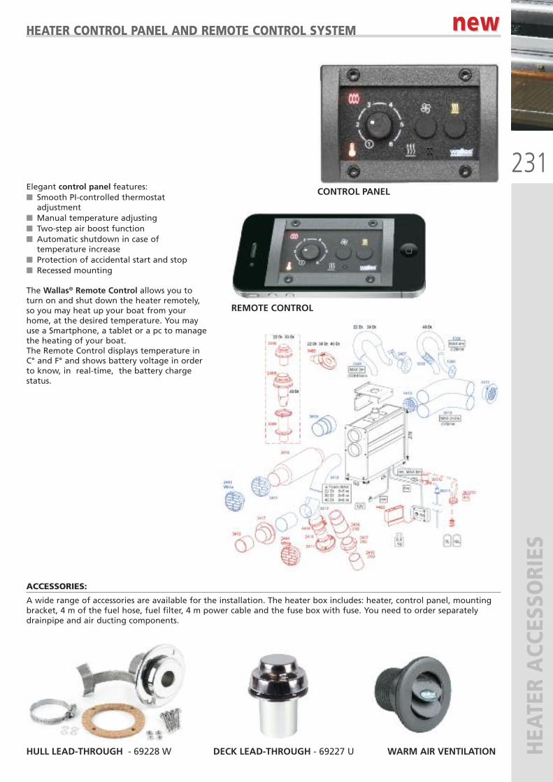
231
HEA
TER ACC
ESSO
RIES
HEATER CONTROL PANEL AND REMOTE CONTROL SYSTEM
Elegant control panel features:� Smooth PI-controlled thermostatadjustment
� Manual temperature adjusting� Two-step air boost function� Automatic shutdown in case oftemperature increase
� Protection of accidental start and stop� Recessed mounting
The Wallas® Remote Control allows you toturn on and shut down the heater remotely,so you may heat up your boat from yourhome, at the desired temperature. You mayuse a Smartphone, a tablet or a pc to managethe heating of your boat. The Remote Control displays temperature inC° and F° and shows battery voltage in orderto know, in real-time, the battery chargestatus.
ACCESSORIES:
A wide range of accessories are available for the installation. The heater box includes: heater, control panel, mountingbracket, 4 m of the fuel hose, fuel filter, 4 m power cable and the fuse box with fuse. You need to order separatelydrainpipe and air ducting components.
new new
CONTROL PANEL
REMOTE CONTROL
HULL LEAD-THROUGH - 69228 W DECK LEAD-THROUGH - 69227 U WARM AIR VENTILATION
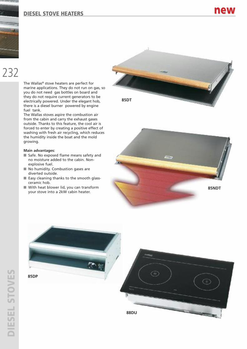
232
DIESE
L STOVES
DIESEL STOVE HEATERS
The Wallas® stove heaters are perfect formarine applications. They do not run on gas, soyou do not need gas bottles on board andthey do not require current generators to beelectrically powered. Under the elegant hob,there is a diesel burner powered by enginefuel tank. The Wallas stoves aspire the combustion airfrom the cabin and carry the exhaust gasesoutside. Thanks to this feature, the cool air isforced to enter by creating a positive effect ofwashing with fresh air recycling, which reducesthe humidity inside the boat and the moldgrowing.
Main advantages:� Safe. No exposed flame means safety andno moisture added to the cabin. Non-explosive fuel.
� No humidity. Combustion gases arediverted outside.
� Easy cleaning thanks to the smooth glass-ceramic hob.
� With heat blower lid, you can transformyour stove into a 2kW cabin heater.
new new
85DT
85DP
88DU
85NDT
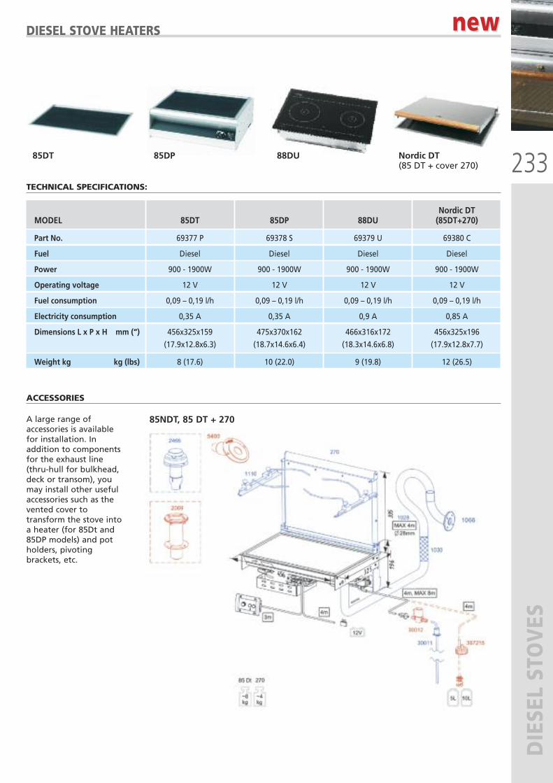
233
DIESE
L STOVES
DIESEL STOVE HEATERS
85DT 85DP 88DU Nordic DT(85 DT + cover 270)
Nordic DT MODEL 85DT 85DP 88DU (85DT+270)
Part No. 69377 P 69378 S 69379 U 69380 C
Fuel Diesel Diesel Diesel Diesel
Power 900 - 1900W 900 - 1900W 900 - 1900W 900 - 1900W
Operating voltage 12 V 12 V 12 V 12 V
Fuel consumption 0,09 – 0,19 l/h 0,09 – 0,19 l/h 0,09 – 0,19 l/h 0,09 – 0,19 l/h
Electricity consumption 0,35 A 0,35 A 0,9 A 0,85 A
Dimensions L x P x H mm (“) 456x325x159 475x370x162 466x316x172 456x325x196
(17.9x12.8x6.3) (18.7x14.6x6.4) (18.3x14.6x6.8) (17.9x12.8x7.7)
Weight kg kg (lbs) 8 (17.6) 10 (22.0) 9 (19.8) 12 (26.5)
TECHNICAL SPECIFICATIONS:
ACCESSORIES
A large range ofaccessories is availablefor installation. Inaddition to componentsfor the exhaust line(thru-hull for bulkhead,deck or transom), youmay install other usefulaccessories such as thevented cover totransform the stove intoa heater (for 85Dt and85DP models) and potholders, pivotingbrackets, etc.
85NDT, 85 DT + 270
new new
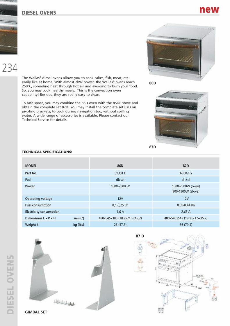
234
DIESE
L OVEN
SDIESEL OVENS
The Wallas® diesel ovens allows you to cook cakes, fish, meat, etc.easily like at home. With almost 2kW power, the Wallas® ovens reach250°C, spreading heat through hot air and avoiding to burn your food.So, you may cook healthy meals. This is the convection ovencapability! Besides, they are really easy to clean.
To safe space, you may combine the 86D oven with the 85DP stove andobtain the complete set 87D. You may install the complete set 87D onpivoting brackets, to cook during navigation too, without spillingwater. A wide range of accessories is available. Please contact ourTechnical Service for details.
86D
87D
MODEL 86D 87D
Part No. 69381 E 69382 G
Fuel diesel diesel
Power 1000-2500 W 1000-2500W (oven)
900-1900W (stove)
Operating voltage 12V 12V
Fuel consumption 0,1-0,25 l/h 0,09-0,44 l/h
Electricity consumption 1,6 A 2,66 A
Dimensions L x P x H mm (“) 480x545x385 (18.9x21.5x15.2) 480x545x542 (18.9x21.5x15.2)
Weight k kg (lbs) 26 (57.3) 36 (79.4)
TECHNICAL SPECIFICATIONS:
87 D
new new
GIMBAL SET
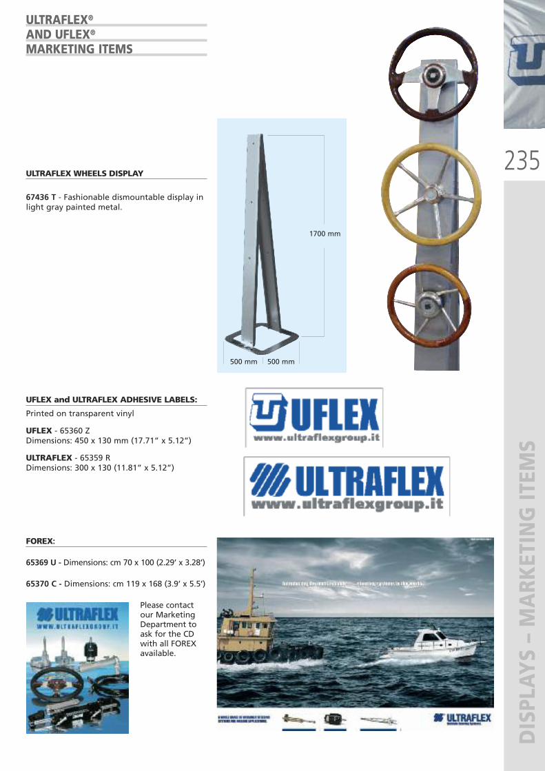
235
DISPLAY
S – MARK
ETING IT
EMS
ULTRAFLEX WHEELS DISPLAY
67436 T - Fashionable dismountable display inlight gray painted metal.
ULTRAFLEX®
AND UFLEX®
MARKETING ITEMS
UFLEX and ULTRAFLEX ADHESIVE LABELS:
Printed on transparent vinyl
UFLEX - 65360 ZDimensions: 450 x 130 mm (17.71” x 5.12”)
ULTRAFLEX - 65359 RDimensions: 300 x 130 (11.81” x 5.12”)
500 mm 500 mm
1700 mm
FOREX:
65369 U - Dimensions: cm 70 x 100 (2.29’ x 3.28’)
65370 C - Dimensions: cm 119 x 168 (3.9’ x 5.5’)
Please contactour MarketingDepartment toask for the CDwith all FOREXavailable.
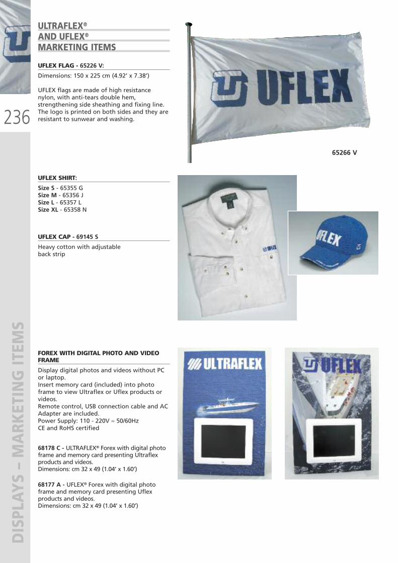
236
DISPLAY
S – MARK
ETING IT
EMS
65266 V
ULTRAFLEX®
AND UFLEX®
MARKETING ITEMS
UFLEX FLAG - 65226 V:
Dimensions: 150 x 225 cm (4.92’ x 7.38’)
UFLEX flags are made of high resistancenylon, with anti-tears double hem,strengthening side sheathing and fixing line.The logo is printed on both sides and they areresistant to sunwear and washing.
UFLEX SHIRT:
Size S - 65355 GSize M - 65356 JSize L - 65357 LSize XL - 65358 N
UFLEX CAP - 69145 S
Heavy cotton with adjustableback strip
FOREX WITH DIGITAL PHOTO AND VIDEOFRAME
Display digital photos and videos without PCor laptop.Insert memory card (included) into photoframe to view Ultraflex or Uflex products orvideos.Remote control, USB connection cable and ACAdapter are included.Power Supply: 110 - 220V ≈ 50/60HzCE and RoHS certified
68178 C - ULTRAFLEX® Forex with digital photoframe and memory card presenting Ultraflexproducts and videos. Dimensions: cm 32 x 49 (1.04’ x 1.60’)
68177 A - UFLEX® Forex with digital photoframe and memory card presenting Uflexproducts and videos.Dimensions: cm 32 x 49 (1.04’ x 1.60’)

Cover picture: P
hoto courtesy of Cantiere del Pardo
Via Milite Ignoto 8A16012 Busalla (GE) - ItalyT +39 010 9620310/266 F +39 010 [email protected]
UFLEX s.r.l. ULTRAFLEX GROUP