Embed Size (px)
Citation preview
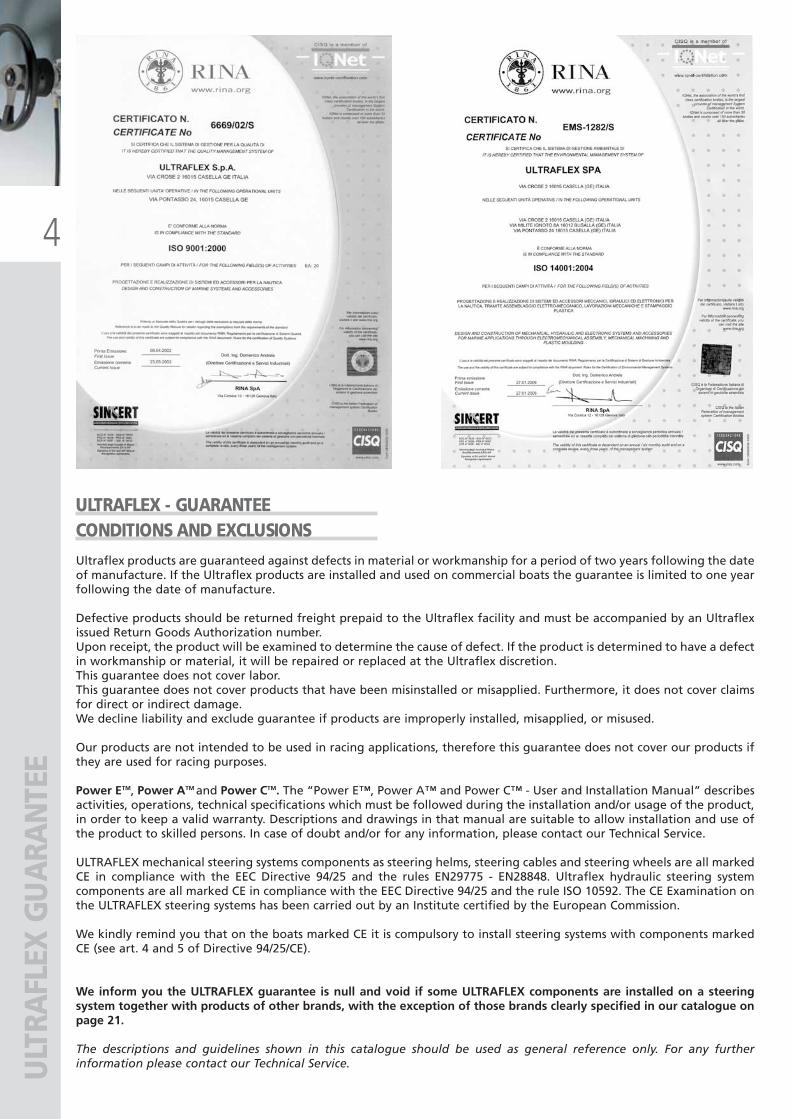
SilverSteer™ tilt mount helm pumps page 54
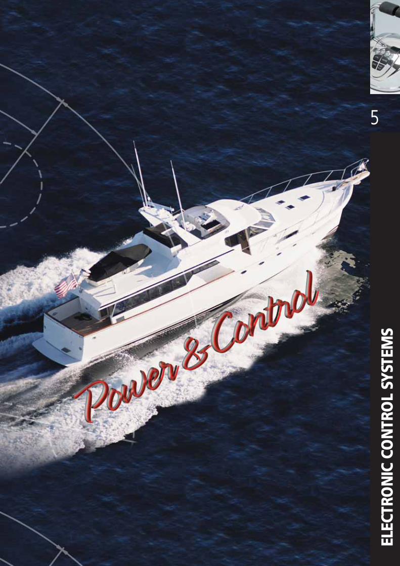
Santorini B/S page 76 Control cable for Jet Weber� engines page 103
X70-SVS tilt mechanism for SilverSteer™helm pumps page 54
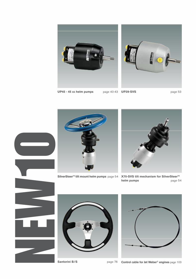
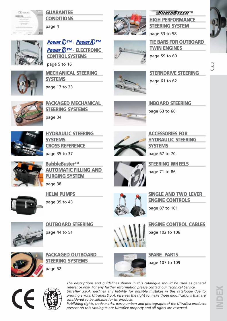
UP45 - 45 cc helm pumps page 40-43 UP39-SVS page 53
NEW
10109
SPA
RE P
ART
S –
HYD
RAU
LIC
PRO
DU
CTS
WARNINGIn order to mantainthe correctfunctionality of theproduct, thereplacement withspare parts has to bemade by qualifiedtechnicians only.
HELM PUMPSVented filler plug kit with valve 40801 NNon vented filler plug kit 40800 LShaft seal kit 40875 V
Installation kit for UP20 F 40248 RInstallation kit for UP20 T 39501 TInstallation kit for:
UP25 F/25NV F/28 F/33 F/33NV F/39 F/UP28F-SVS, UP33F-SVS 39476 XInstallation kit for UP25 T/28 T/33 T/39 T 39501 TInstallation kit for UP28 R/33 R/39 R 39500 R
Nylon round flange for X57 70666 ENylon square flange for X64 70670 VChrome plated cover ring - X68 40894 ZPump filling kit 40876 X
UC94-OBF OUTBOARD CYLINDERBlack bull horn mounting bracket 40877 ZThrough tube stainless steel rod 40174 M
Spacer kit 40878 B
UC128-OBF OUTBOARD CYLINDERBlack bull horn mounting bracket 39490 RThrough tube stainless steel rod 39491 T
Spacer kit 41812 ZPlastic cap kit 41810 VUC128 Hardware kit 39979 ATiller arm connecting (ultrabolt) 40822 X(suitable also for UC128-SVS)
UC68-OBS OUTBOARD CYLINDERStainless steel tilt tube extension 39495 B
UC132-OBS OUTBOARD CYLINDERStainless steel tilt tube extension 39495 BExtension rod connecting pin 40917 J
INBOARD CYLINDERSBalljoint for UC69-I 40883 UBalljoint for UC116-I 39477 ZBalljoint for UC168-I and UC215-I 39478 BBalljoint for UC293-I 40178 WBalljoint for UC378-I 41310 Y
Balljoint and shim for UC69-I 40884 WBalljoint and shim for UC116-I 39479 DBalljoint and shim for UC168-I e UC215-I 39480 MBalljoint and shim for UC293-I 40180 GBalljoint and shim for UC378-I 41311 A
STERNDRIVE CYLINDERSExtension rod connecting pin 40917 J
NUT AND SLEEVEBrass nut and sleeve 71004 KNickel plated brass nut and sleeve 71013 L
HYDRAULICPRODUCTS
AVAILABLESPAREPARTS
ULTRAFLEX2010_ENG_Cop+Dorso:ULTRAFLEX2009_ITA_Cop+Dorso.qxd 18/09/09 14:36 Pagina 2

UFLEX
ULTRAFLEX
UFLEX - Divisione energia
ULTRAFLEX CONTROL SYSTEMS
INDUSTRIA di LEIVI
UFLEX USA
MARESI LTD
®
ULTRAFLEX GROUP
Magnetic compasses
Window and skylight remote controls.Innovative LED road signs
Mechanical remote controls in the industrial field
Manufacturing the world’s finest marine products
Worldwide distribution of marine accessories
Steering and control systems for pleasure boats
1935 - 2009Ultraflex Group has 74 years of experience in manufacturing
and distributing the highest quality and most innovative products.
The Ultraflex Group affiliate Companies that design and produce widely
known equipments in the marine, industrial, architectural,
Led technology and alternative energy fields.
Systems and accessories for alternative energy applications
ULTRAFLEX2010-Ita:ULTRAFLEX2009-Ita.qxd 21/09/09 16:19 Pagina 1

Factory in Casella
Factory in Borgo Fornari
Quality Management SystemThe Ultraflex Quality Management Systems is certified CISQ-IQNet by
the Italian Shipping Registry (RINA), in conformity with the UNI EN ISO
9001:2000 rule. Ultraflex certification n° 6669/02/S (former 420/96).
The quality management system involves all the company resources
and processes starting from the design, in order to:
• Assure product quality to the customer
• Set up the actions to maintain and improve the quality standards
constantly
• Pursue a continuous process improvement to meet the market needs
The Ultraflex Environmental Management System is certified
CISQ-IQNet by the Italian Shipping Registry (RINA), in conformity with
the UNI EN ISO 14001:2004. Ultraflex certification n° EMS-1282/S.
Constantly test the products to verify their conformity with the EEC
94/25 and ABYC (American Boat and Yacht Council) requirements.
ULTRAFLEX2010-Ita:ULTRAFLEX2009-Ita.qxd 21/09/09 16:19 Pagina 2
3
IND
EX
The descriptions and guidelines shown in this catalogue should be used as generalreference only. For any further information please contact our Technical Service.
GUARANTEECONDITIONSpage 4
MECHANICAL STEERINGSYSTEMSpage 17 to 33
INBOARD STEERINGpage 63 to 66
PACKAGED MECHANICALSTEERING SYSTEMSpage 34
ACCESSORIES FORHYDRAULIC STEERINGSYSTEMSpage 67 to 70
HYDRAULIC STEERINGSYSTEMSCROSS REFERENCEpage 35 to 37
STEERING WHEELSpage 71 to 86
BubbleBuster™ AUTOMATIC FILLING ANDPURGING SYSTEMpage 38
SINGLE AND TWO LEVERENGINE CONTROLSpage 87 to 101
HELM PUMPSpage 39 to 43
ENGINE CONTROL CABLESpage 102 to 106
OUTBOARD STEERING page 44 to 51
SPARE PARTSpage 107 to 109
PACKAGED OUTBOARDSTEERING SYSTEMSpage 52
-- ELECTRONIC
CONTROL SYSTEMSpage 5 to 16
TIE BARS FOR OUTBOARDTWIN ENGINESpage 59 to 60
STERNDRIVE STEERINGpage 61 to 62
HIGH PERFORMANCE STEERING SYSTEMpage 53 to 58
Power E ™ Power A ™
Power C ™
Ultraflex S.p.A. declines any liability for possible mistakes in this catalogue due toprinting errors. Ultraflex S.p.A. reserves the right to make those modifications that areconsidered to be suitable for its products. Publishing rights, trade marks, part numbers and photographs of the Ultraflex productspresent on this catalogue are Ultraflex property and all rights are reserved.
ULTRAFLEX2010-Ita:ULTRAFLEX2009-Ita.qxd 18/09/09 17:02 Pagina 3
4
ULT
RAFL
EX G
UA
RAN
TEE
Ultraflex products are guaranteed against defects in material or workmanship for a period of two years following the dateof manufacture. If the Ultraflex products are installed and used on commercial boats the guarantee is limited to one yearfollowing the date of manufacture.
Defective products should be returned freight prepaid to the Ultraflex facility and must be accompanied by an Ultraflexissued Return Goods Authorization number.Upon receipt, the product will be examined to determine the cause of defect. If the product is determined to have a defectin workmanship or material, it will be repaired or replaced at the Ultraflex discretion.This guarantee does not cover labor.This guarantee does not cover products that have been misinstalled or misapplied. Furthermore, it does not cover claimsfor direct or indirect damage.We decline liability and exclude guarantee if products are improperly installed, misapplied, or misused.
Our products are not intended to be used in racing applications, therefore this guarantee does not cover our products ifthey are used for racing purposes.
Power ETM, Power ATM and Power CTM. The “Power E™, Power A™ and Power C™ - User and Installation Manual” describesactivities, operations, technical specifications which must be followed during the installation and/or usage of the product,in order to keep a valid warranty. Descriptions and drawings in that manual are suitable to allow installation and use ofthe product to skilled persons. In case of doubt and/or for any information, please contact our Technical Service.
ULTRAFLEX mechanical steering systems components as steering helms, steering cables and steering wheels are all markedCE in compliance with the EEC Directive 94/25 and the rules EN29775 - EN28848. Ultraflex hydraulic steering systemcomponents are all marked CE in compliance with the EEC Directive 94/25 and the rule ISO 10592. The CE Examination onthe ULTRAFLEX steering systems has been carried out by an Institute certified by the European Commission.
We kindly remind you that on the boats marked CE it is compulsory to install steering systems with components markedCE (see art. 4 and 5 of Directive 94/25/CE).
We inform you the ULTRAFLEX guarantee is null and void if some ULTRAFLEX components are installed on a steeringsystem together with products of other brands, with the exception of those brands clearly specified in our catalogue onpage 21.
The descriptions and guidelines shown in this catalogue should be used as general reference only. For any furtherinformation please contact our Technical Service.
ULTRAFLEX - GUARANTEE CONDITIONS AND EXCLUSIONS
ULTRAFLEX2010-Ita:ULTRAFLEX2009-Ita.qxd 18/09/09 17:02 Pagina 4
ELEC
TRO
NIC
CO
NTR
OL
SYST
EMS
ELEC
TRO
NIC
CO
NTR
OL
SYST
EMS
ULTRAFLEX2010-Ita:ULTRAFLEX2009-Ita.qxd 18/09/09 17:02 Pagina 5
6
Pow
er E
™Po
wer
E™
Power E ™- E
LECT
RON
IC C
ON
TRO
L SY
STEM
ELECTRONIC CONTROL SYSTEM
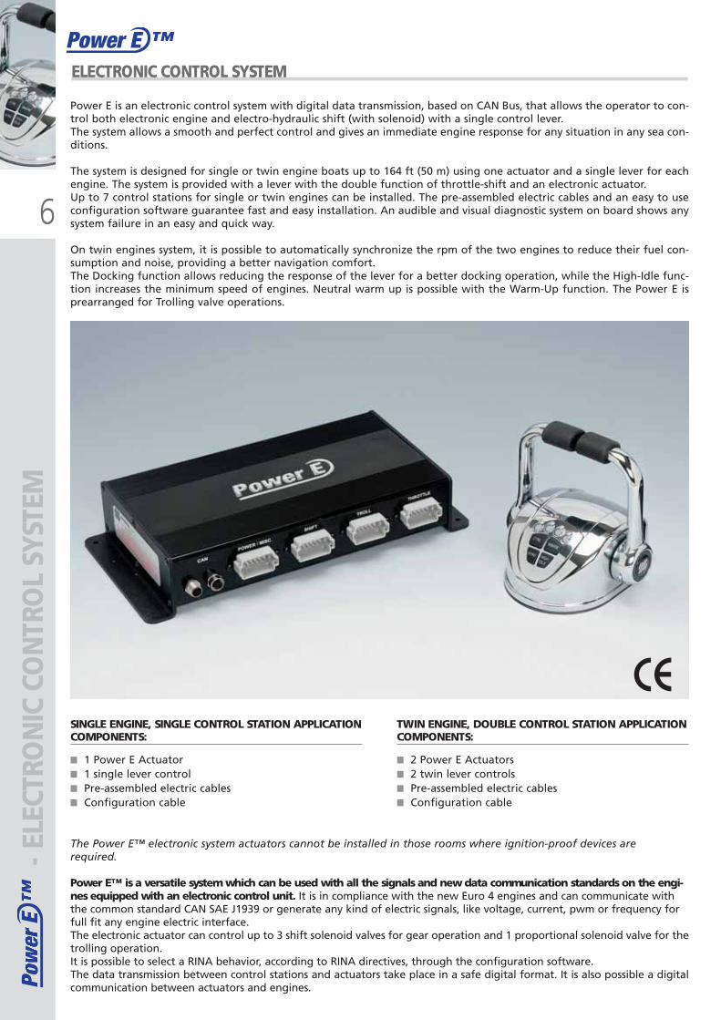
SINGLE ENGINE, SINGLE CONTROL STATION APPLICATION COMPONENTS:
■ 1 Power E Actuator■ 1 single lever control■ Pre-assembled electric cables■ Configuration cable
TWIN ENGINE, DOUBLE CONTROL STATION APPLICATION COMPONENTS:
■ 2 Power E Actuators■ 2 twin lever controls■ Pre-assembled electric cables■ Configuration cable
The Power E™ electronic system actuators cannot be installed in those rooms where ignition-proof devices are required.
Power E™ is a versatile system which can be used with all the signals and new data communication standards on the engi-nes equipped with an electronic control unit. It is in compliance with the new Euro 4 engines and can communicate withthe common standard CAN SAE J1939 or generate any kind of electric signals, like voltage, current, pwm or frequency forfull fit any engine electric interface.The electronic actuator can control up to 3 shift solenoid valves for gear operation and 1 proportional solenoid valve for thetrolling operation.It is possible to select a RINA behavior, according to RINA directives, through the configuration software.The data transmission between control stations and actuators take place in a safe digital format. It is also possible a digitalcommunication between actuators and engines.
Power E is an electronic control system with digital data transmission, based on CAN Bus, that allows the operator to con-trol both electronic engine and electro-hydraulic shift (with solenoid) with a single control lever.The system allows a smooth and perfect control and gives an immediate engine response for any situation in any sea con-ditions.
The system is designed for single or twin engine boats up to 164 ft (50 m) using one actuator and a single lever for eachengine. The system is provided with a lever with the double function of throttle-shift and an electronic actuator.Up to 7 control stations for single or twin engines can be installed. The pre-assembled electric cables and an easy to useconfiguration software guarantee fast and easy installation. An audible and visual diagnostic system on board shows anysystem failure in an easy and quick way.
On twin engines system, it is possible to automatically synchronize the rpm of the two engines to reduce their fuel con-sumption and noise, providing a better navigation comfort.The Docking function allows reducing the response of the lever for a better docking operation, while the High-Idle func-tion increases the minimum speed of engines. Neutral warm up is possible with the Warm-Up function. The Power E isprearranged for Trolling valve operations.
ULTRAFLEX2010-Ita:ULTRAFLEX2009-Ita.qxd 18/09/09 17:02 Pagina 6
7
Pow
er E
™Po
wer
E™
Power E ™
- ELE
CTRO
NIC
CO
NTR
OL
SYST
EM
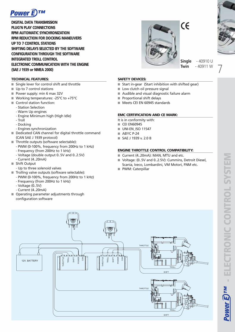
TECHNICAL FEATURES:■ Single lever for control shift and throttle■ Up to 7 control stations■ Power supply: min 6 max 32V■ Working temperatures: -25°C to +75°C■ Control station function:
- Station Selection- Warm Up engines- Engine Minimum high (High Idle)- Troll- Docking- Engines synchronization
■ Dedicated CAN channel for digital throttle command(CAN SAE J 1939 protocol)
■ Throttle outputs (software selectable):- PWM (0-100%, frequency from 200Hz to 1 kHz)- Frequency (from 200Hz to 1 kHz)- Voltage (double output 0..5V and 0..2.5V)- Current (4..20mA)
■ Shift Output- Up to three solenoid valves
■ Trolling valve outputs (software selectable):- PWM (0-100%, frequency from 200Hz to 1 kHz)- Frequency (from 200Hz to 1 kHz)- Voltage (0..5V)- Current (4..20mA)
■ Operating parameter adjustments throughconfiguration software
SAFETY DEVICES:■ Start in-gear (Start inhibition with shifted gear)■ Low clutch oil pressure signal■ Audible and visual diagnostic failure alarm■ Proportional shift delays■ Meets CEI EN 60945 standards
EMC CERTIFICATION AND CE MARK:It is in conformity with: ■ CEI EN60945■ UNI-EN_ISO 11547■ ABYC P-24■ SAE J 1939 v. 2.0 B
ENGINE THROTTLE CONTROL COMPATIBILITY:■ Current (4..20mA): MAN, MTU and etc.■ Voltage: (0..5V and 0..2.5V): Cummins, Detroit Diesel,
Scania, Iveco, Lombardini, VM Motori, FNM etc.■ PWM: Caterpillar
Single - 40910 U Twin - 40911 W
DIGITAL DATA TRANSMISSIONPLUG’N PLAY CONNECTIONSRPM AUTOMATIC SYNCHRONIZATION RPM REDUCTION FOR DOCKING MANEUVERSUP TO 7 CONTROL STATIONSSHIFTING DELAYS SELECTED BY THE SOFTWARECONFIGURATION THROUGH THE SOFTWAREINTEGRATED TROLL CONTROLELECTRONIC COMMUNICATION WITH THE ENGINE (SAE J 1939 or NMEA 2000)
ULTRAFLEX2010-Ita:ULTRAFLEX2009-Ita.qxd 18/09/09 17:02 Pagina 7
8
Pow
er E
™Po
wer
E™
Power E ™
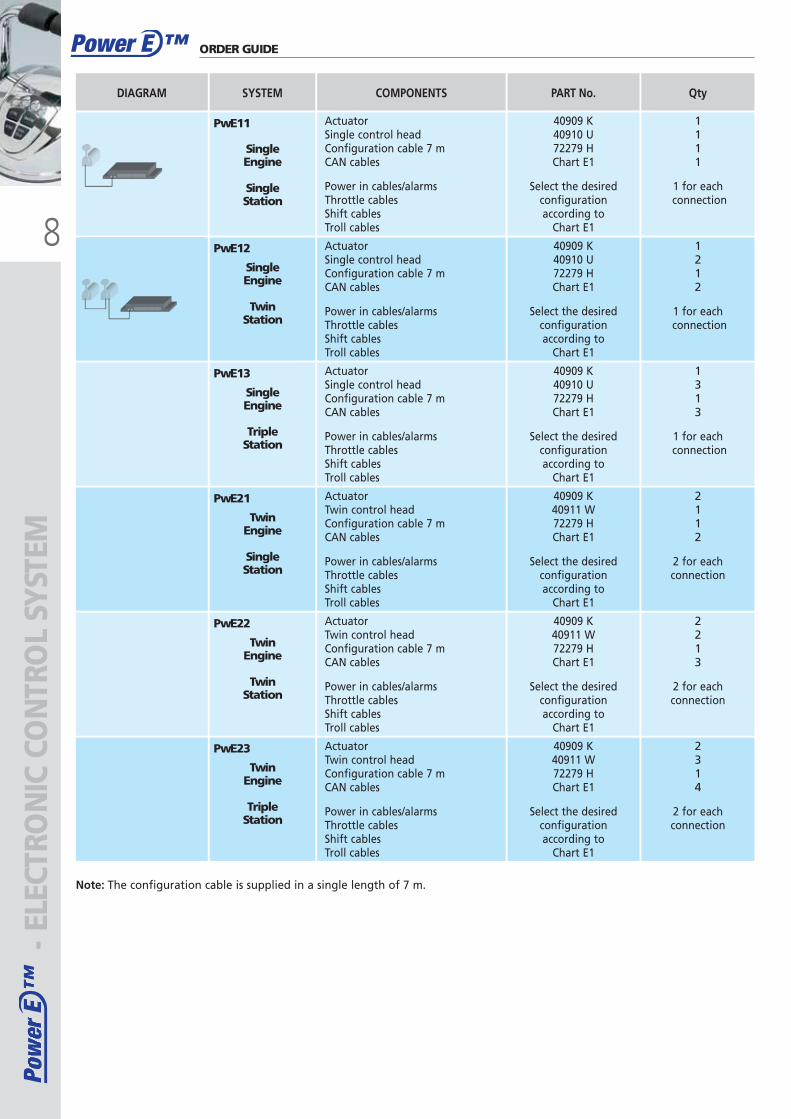
SingleEngine
SingleStation
SYSTEMDIAGRAM
ActuatorSingle control headConfiguration cable 7 m CAN cables
Power in cables/alarmsThrottle cablesShift cablesTroll cables
1111
1 for eachconnection
QtyCOMPONENTS
40909 K40910 U 72279 HChart E1
Select the desiredconfigurationaccording to
Chart E1
PART No.
SingleEngine
TripleStation
ActuatorSingle control headConfiguration cable 7 mCAN cables
Power in cables/alarmsThrottle cablesShift cablesTroll cables
1313
1 for eachconnection
40909 K40910 U 72279 HChart E1
Select the desiredconfigurationaccording to
Chart E1
Twin Engine
SingleStation
ActuatorTwin control headConfiguration cable 7 m CAN cables
Power in cables/alarmsThrottle cablesShift cablesTroll cables
2112
2 for each connection
40909 K40911 W72279 HChart E1
Select the desiredconfigurationaccording to
Chart E1
Twin Engine
Twin Station
ActuatorTwin control headConfiguration cable 7 mCAN cables
Power in cables/alarmsThrottle cablesShift cablesTroll cables
2213
2 for each connection
40909 K40911 W72279 HChart E1
Select the desiredconfigurationaccording to
Chart E1
Twin Engine
TripleStation
ActuatorTwin control headConfiguration cable 7 mCAN cables
Power in cables/alarmsThrottle cablesShift cablesTroll cables
2314
2 for each connection
40909 K40911 W72279 HChart E1
Select the desiredconfigurationaccording to
Chart E1
SingleEngine
Twin Station
ActuatorSingle control headConfiguration cable 7 m CAN cables
Power in cables/alarmsThrottle cablesShift cablesTroll cables
1212
1 for eachconnection
40909 K40910 U 72279 HChart E1
Select the desiredconfigurationaccording to
Chart E1
PwE11
PwE12
PwE13
PwE21
PwE22
PwE23
- ELE
CTRO
NIC
CO
NTR
OL
SYST
EMORDER GUIDE
Note: The configuration cable is supplied in a single length of 7 m.
ULTRAFLEX2010-Ita:ULTRAFLEX2009-Ita.qxd 18/09/09 17:02 Pagina 8
9
Pow
er E
™Po
wer
E™
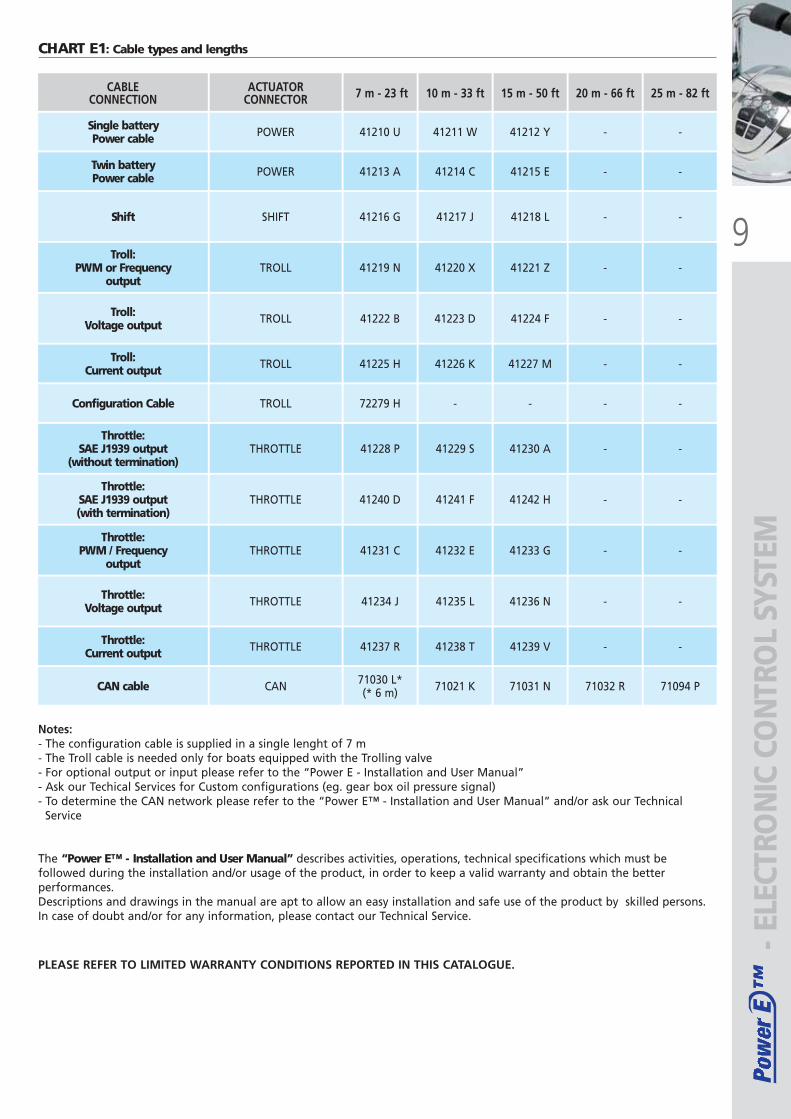
Single batteryPower cable POWER
ACTUATORCONNECTOR
Twin battery Power cable POWER
Shift SHIFT
Troll:PWM or Frequency
outputTROLL
Troll:Voltage output TROLL
Troll:Current output TROLL
Configuration Cable TROLL
Throttle:SAE J1939 output
(without termination)THROTTLE
Throttle:SAE J1939 output(with termination)
THROTTLE
Throttle:Voltage output THROTTLE
Throttle:Current output THROTTLE
CAN cable CAN
41210 U
7 m - 23 ft
41213 A
41216 G
41219 N
41222 B
41225 H
72279 H
41228 P
41240 D
41234 J
41237 R
71030 L*(* 6 m)
41211 W
10 m - 33 ft
41214 C
41217 J
41220 X
41223 D
41226 K
-
41229 S
41241 F
41235 L
41238 T
71021 K
41212 Y
15 m - 50 ft
41215 E
41218 L
41221 Z
41224 F
41227 M
-
41230 A
41242 H
41236 N
41239 V
71031 N
-
20 m - 66 ft
-
-
-
-
-
-
-
-
-
-
71032 R
-
25 m - 82 ft
-
-
-
-
-
-
-
-
-
Throttle:PWM / Frequency
outputTHROTTLE 41231 C 41232 E 41233 G - -
-
71094 P
CABLECONNECTION
- ELE
CTRO
NIC
CO
NTR
OL
SYST
EM
CHART E1: Cable types and lengths
Notes:- The configuration cable is supplied in a single lenght of 7 m- The Troll cable is needed only for boats equipped with the Trolling valve- For optional output or input please refer to the “Power E - Installation and User Manual”- Ask our Techical Services for Custom configurations (eg. gear box oil pressure signal)- To determine the CAN network please refer to the “Power E™ - Installation and User Manual” and/or ask our Technical
Service
The “Power E™ - Installation and User Manual” describes activities, operations, technical specifications which must befollowed during the installation and/or usage of the product, in order to keep a valid warranty and obtain the betterperformances.Descriptions and drawings in the manual are apt to allow an easy installation and safe use of the product by skilled persons.In case of doubt and/or for any information, please contact our Technical Service.
PLEASE REFER TO LIMITED WARRANTY CONDITIONS REPORTED IN THIS CATALOGUE.
ULTRAFLEX2010-Ita:ULTRAFLEX2009-Ita.qxd 18/09/09 17:02 Pagina 9
10
Pow
er A
™Po
wer
A™
Power A ™
41074 N
41072 J - ELE
CTRO
NIC
CO
NTR
OL
SYST
EMELECTRONIC CONTROL SYSTEM
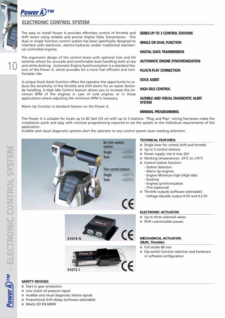
The easy to install Power A provides effortless control of throttle andshift levers using reliable and precise Digital Data Transmission. Thisdual or single function control system has been specifically designed tointerface with electronic, electro-hydraulic and/or traditional mechani-cal controlled engines.
The ergonomic design of the control levers with optional trim and tiltswitches allows for accurate and comfortable boat handling both at seaand while docking. Automatic Engine Synchronization is a standard fea-ture of the Power A, which provides for a more fuel efficient and com-fortable ride.
A unique Dock Assist function offers the operator the opportunity to re-duce the sensitivity of the throttle and shift levers for an easier docksi-de handling. A High Idle Control feature allows you to increase the mi-nimum RPM of the engines in case of cold engines or in thoseapplications where adjusting the minimum RPM is necessary.
Warm Up function is standard feature on the Power A.
The Power A is suitable for boats up to 82 feet (25 m) with up to 3 stations. “Plug and Play” wiring harnesses make theinstallation quick and easy with minimal programming required to set the system to the individual requirements of theapplication.Audible and visual diagnostic systems alert the operator to any control system issue needing attention.
SERIES UP TO 3 CONTROL STATIONS
SINGLE OR DUAL FUNCTION
DIGITAL DATA TRANSMISSION
AUTOMATIC ENGINE SYNCHRONIZATION
PLUG’N PLAY CONNECTION
DOCK ASSIST
HIGH IDLE CONTROL
AUDIBLE AND VISUAL DIAGNOSTIC ALERTSYSTEM
MINIMAL PROGRAMMING
SAFETY DEVICES:■ Start-in gear protection■ Low clutch oil pressure signal■ Audible and visual diagnostic failure signals■ Proportional shift delays (software selectable)■ Meets CEI EN 60945
No trim controlstation:Single - 41076 TTwin - 41078 X
Trim control station:Single - 41077 VTwin - 41079 Z
TECHNICAL FEATURES:■ Single lever for control shift and throttle■ Up to 3 control stations■ Power supply: min 6 max 32V■ Working temperatures: -25°C to +75°C■ Control station function:
- Station Selection- Warm Up engines- Engine Minimum high (High Idle)- Docking- Engines synchronization- Trim (optional)
■ Throttle outputs (software selectable):- Voltage (double output 0-5V and 0-2.5V
ELECTRONIC ACTUATOR:■ Up to three solenoid valves ■ Shift customizable pauses
MECHANICAL ACTUATOR:(Shift, Throttle)■ Full stroke 80 mm■ Dip-switch function selection and hardware
or software configuration
ULTRAFLEX2010-Ita:ULTRAFLEX2009-Ita.qxd 18/09/09 17:02 Pagina 10
11
Pow
er A
™Po
wer
A™
Power A ™
SYSTEM
ElectronicThrottle
Mechanicalshift
ENGINE
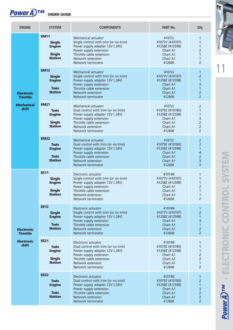
Mechanical actuatorSingle control with trim (or no trim)Power supply adapter 12V ( 24V)Power supply extensionThrottle cable extensionNetwork extensionNetwork terminator
1112112
QtyCOMPONENTS
41072J41077V (41076T)41258Z (41259B)
Chart A1Chart A1Chart A141260K
Mechanical actuatorSingle control with trim (or no trim)Power supply adapter 12V ( 24V)Power supply extensionThrottle cable extensionNetwork extensionNetwork terminator
1213122
41072J41077V (41076T)41258Z (41259B)
Chart A1Chart A1Chart A141260K
Mechanical actuatorDual control with trim (or no trim)Power supply adapter 12V ( 24V)Power supply extensionThrottle cable extensionNetwork extensionNetwork terminator
2113222
41072J41079Z (41078X)41258Z (41259B)
Chart A1Chart A1Chart A141260K
Mechanical actuatorDual control with trim (or no trim)Power supply adapter 12V ( 24V)Power supply extensionThrottle cable extensionNetwork extensionNetwork terminator
2214232
41072J41079Z (41078X)41258Z (41259B)
Chart A1Chart A1Chart A141260K
SingleEngine
SingleStation
ElectronicThrottle
Electronicshift
Electronic actuatorSingle control with trim (or no trim)Power supply adapter 12V ( 24V)Power supply extensionThrottle cable extensionNetwork extensionNetwork terminator
1112112
41074N41077V (41076T)41258Z (41259B)
Chart A1Chart A1Chart A141260K
SingleEngine
TwinStation
Electronic actuatorSingle control with trim (or no trim)Power supply adapter 12V ( 24V)Power supply extensionThrottle cable extensionNetwork extensionNetwork terminator
1213122
41074N41077V (41076T)41258Z (41259B)
Chart A1Chart A1Chart A141260K
TwinEngine
SingleStation
Electronic actuatorDual control with trim (or no trim)Power supply adapter 12V ( 24V)Power supply extensionThrottle cable extensionNetwork extensionNetwork terminator
1112212
41074N41079Z (41078X)41258Z (41259B)
Chart A1Chart A1Chart A141260K
TwinEngine
Twin Station
Electronic actuatorDual control with trim (or no trim)Power supply adapter 12V ( 24V)Power supply extensionThrottle cable extensionNetwork extensionNetwork terminator
1213222
41074N41079Z (41078X)41258Z (41259B)
Chart A1Chart A1Chart A141260K
PART No.
ORDER GUIDE
SingleEngine
SingleStation
SingleEngine
TwinStation
TwinEngine
SingleStation
TwinEngine
TwinStation
EM11
EM12
EM21
EM22
EE11
EE12
EE21
EE22 - ELE
CTRO
NIC
CO
NTR
OL
SYST
EM
ULTRAFLEX2010-Ita:ULTRAFLEX2009-Ita.qxd 18/09/09 17:02 Pagina 11
12
Pow
er A
™Po
wer
A™
Power A ™- E
LECT
RON
IC C
ON
TRO
L SY
STEM
SingleEngine
SingleStation
SYSTEM
MechanicalThrottle
Mechanicalshift
ENGINE
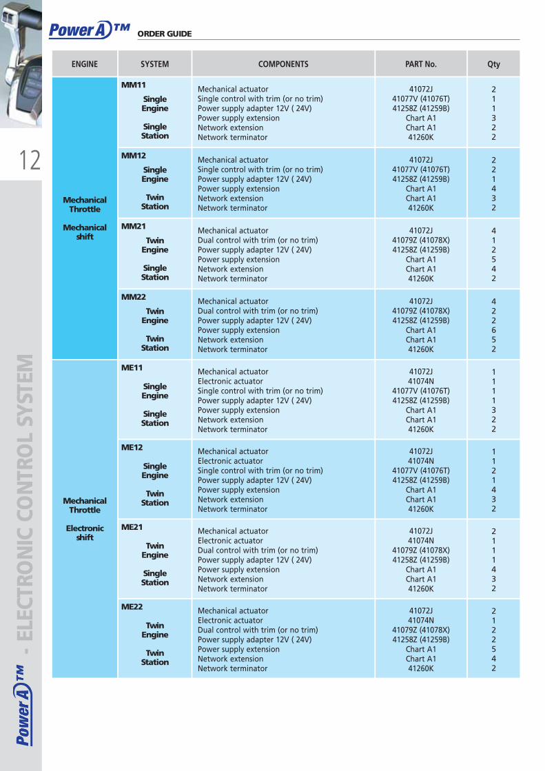
Mechanical actuatorSingle control with trim (or no trim)Power supply adapter 12V ( 24V)Power supply extensionNetwork extensionNetwork terminator
211322
QtyCOMPONENTS
41072J41077V (41076T)41258Z (41259B)
Chart A1Chart A141260K
SingleEngine
TwinStation
Mechanical actuatorSingle control with trim (or no trim)Power supply adapter 12V ( 24V)Power supply extensionNetwork extensionNetwork terminator
221432
41072J41077V (41076T)41258Z (41259B)
Chart A1Chart A141260K
TwinEngine
SingleStation
Mechanical actuatorDual control with trim (or no trim)Power supply adapter 12V ( 24V)Power supply extensionNetwork extensionNetwork terminator
412542
41072J41079Z (41078X)41258Z (41259B)
Chart A1Chart A141260K
TwinEngine
TwinStation
Mechanical actuatorDual control with trim (or no trim)Power supply adapter 12V ( 24V)Power supply extensionNetwork extensionNetwork terminator
422652
41072J41079Z (41078X)41258Z (41259B)
Chart A1Chart A141260K
SingleEngine
SingleStation
MechanicalThrottle
Electronicshift
Mechanical actuatorElectronic actuatorSingle control with trim (or no trim)Power supply adapter 12V ( 24V)Power supply extensionNetwork extensionNetwork terminator
1111322
41072J41074N
41077V (41076T)41258Z (41259B)
Chart A1Chart A141260K
SingleEngine
TwinStation
Mechanical actuatorElectronic actuatorSingle control with trim (or no trim)Power supply adapter 12V ( 24V)Power supply extensionNetwork extensionNetwork terminator
1121432
41072J41074N
41077V (41076T)41258Z (41259B)
Chart A1Chart A141260K
TwinEngine
SingleStation
Mechanical actuatorElectronic actuatorDual control with trim (or no trim)Power supply adapter 12V ( 24V)Power supply extensionNetwork extensionNetwork terminator
2111432
41072J41074N
41079Z (41078X)41258Z (41259B)
Chart A1Chart A141260K
TwinEngine
TwinStation
Mechanical actuatorElectronic actuatorDual control with trim (or no trim)Power supply adapter 12V ( 24V)Power supply extensionNetwork extensionNetwork terminator
2122542
41072J41074N
41079Z (41078X)41258Z (41259B)
Chart A1Chart A141260K
PART No.
ORDER GUIDE
MM11
MM12
MM21
MM22
ME11
ME12
ME21
ME22
ULTRAFLEX2010-Ita:ULTRAFLEX2009-Ita.qxd 18/09/09 17:02 Pagina 12
13
Pow
er A
™Po
wer
A™
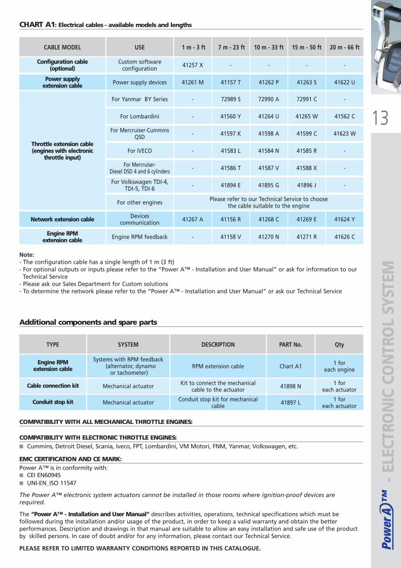
Configuration cable(optional)
CABLE MODEL
Custom softwareconfiguration
USE
-
7 m - 23 ft
-
10 m - 33 ft
-
Power supplyextension cable Power supply devices 41157 T 41262 P 41263 S
Throttle extension cable(engines with electronic
throttle input)
For Yanmar BY Series 72989 S 72990 A 72991 C
41257 X
1 m - 3 ft
41261 M
-
Engine RPM extension cable Engine RPM feedback 41158 V- 41270 N 41271 R
15 m - 50 ft
-
41622 U
-
For Lombardini 41560 Y 41264 U 41265 W- 41562 C
For Mercruiser-CumminsQSD 41597 K 41598 A 41599 C- 41623 W
For IVECO 41583 L 41584 N 41585 R- -
For Mercruiser- Diesel DSD 4 and 6 cylinders 41586 T 41587 V 41588 X- -
For Volkswagen TDI-4,TDI-5, TDI-6 41894 E 41895 G 41896 J- -
For other engines Please refer to our Technical Service to choose the cable suitable to the engine
Network extension cable Devicescommunication 41156 R41267 A 41268 C 41269 E 41624 Y
41626 C
20 m - 66 ft
Note:- The configuration cable has a single length of 1 m (3 ft)- For optional outputs or inputs please refer to the “Power A™ - Installation and User Manual” or ask for information to our
Technical Service- Please ask our Sales Department for Custom solutions- To determine the network please refer to the “Power A™ - Installation and User Manual” or ask our Technical Service
Additional components and spare parts
SYSTEMTYPE QtyDESCRIPTION
Systems with RPM feedback (alternator, dynamo
or tachometer)
Engine RPMextension cable RPM extension cable 1 for
each engineChart A1
Mechanical actuatorCable connection kit Kit to connect the mechanicalcable to the actuator
1 for each actuator41898 N
Mechanical actuatorConduit stop kit Conduit stop kit for mechanicalcable
1 for each actuator41897 L
PART No.
COMPATIBILITY WITH ALL MECHANICAL THROTTLE ENGINES:
COMPATIBILITY WITH ELECTRONIC THROTTLE ENGINES:■ Cummins, Detroit Diesel, Scania, Iveco, FPT, Lombardini, VM Motori, FNM, Yanmar, Volkswagen, etc.
EMC CERTIFICATION AND CE MARK:Power A™ is in conformity with: ■ CEI EN60945■ UNI-EN_ISO 11547
The Power A™ electronic system actuators cannot be installed in those rooms where ignition-proof devices are required.
The “Power A™ - Installation and User Manual” describes activities, operations, technical specifications which must befollowed during the installation and/or usage of the product, in order to keep a valid warranty and obtain the betterperformances. Description and drawings in that manual are suitable to allow an easy installation and safe use of the productby skilled persons. In case of doubt and/or for any information, please contact our Technical Service.
PLEASE REFER TO LIMITED WARRANTY CONDITIONS REPORTED IN THIS CATALOGUE.
CHART A1: Electrical cables - available models and lengths
- ELE
CTRO
NIC
CO
NTR
OL
SYST
EM
ULTRAFLEX2010-Ita:ULTRAFLEX2009-Ita.qxd 21/09/09 16:19 Pagina 13
14
Power C ™Po
wer
C™
Pow
er C
™
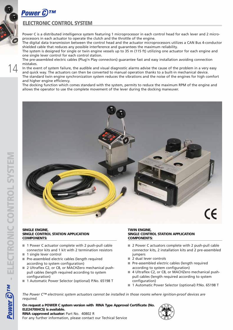
ELECTRONIC CONTROL SYSTEM
SINGLE ENGINE,SINGLE CONTROL STATION APPLICATIONCOMPONENTS:
■ 1 Power C actuator complete with 2 push-pull cableconnector kits and 1 kit with 2 termination resistors
■ 1 single lever control■ Pre-assembled electric cables (length required
according to system configuration)■ 2 Ultraflex C2, or C8, or MACHZero mechanical push-
pull cables (length required according to systemconfiguration)
■ 1 Automatic Power Selector (optional) P.No. 65198 T
TWIN ENGINE,SINGLE CONTROL STATION APPLICATIONCOMPONENTS:
■ 2 Power C actuators complete with 2 push-pull cableconnector kits, 2 installation kits and 2 pre-assembledjumpers
■ 2 dual lever controls■ Pre-assembled electric cables (length required
according to system configuration)■ 4 Ultraflex C2, or C8, or MACHZero mechanical push-
pull cables (length required according to systemconfiguration)
■ 1 Automatic Power Selector (optional) P.No. 65198 T
The Power C™ electronic system actuators cannot be installed in those rooms where ignition-proof devices are required.
Power C is a distributed intelligence system featuring 1 microprocessor in each control head for each lever and 2 micro-processors in each actuator to operate the clutch and the throttle of the engine.The digital data transmission between the control head and the actuator microprocessors utilizes a CAN Bus 4-conductorshielded cable that reduces any possible interference and guarantees the maximum reliability.The system is designed for single or twin engine vessels up to 35 m (115 ft) utilizing one actuator for each engine andone single lever control for each control station.The pre-assembled electric cables (Plug’n Play connectors) guarantee fast and easy installation avoiding connectionmistakes.In the event of system failure, the audible and visual diagnostic alarms advise the cause of the problem in a very easyand quick way. The actuators can then be converted to manual operation thanks to a built-in mechanical device.The standard twin engine synchronization system reduces the vibrations and the noise of the engines for high comfortand higher engine efficiency.The docking function which comes standard with the system, permits to reduce the maximum RPM of the engine andallows the operator to use the complete movement of the lever during the docking maneuver.
- ELE
CTRO
NIC
CO
NTR
OL
SYST
EM
On request a POWER C system version with RINA Type Approval Certificate (No.ELE247004CS) is available.RINA capproved actuator: Part No. 40802 RFor any further information, please contact our Techical Service
ULTRAFLEX2010-Ita:ULTRAFLEX2009-Ita.qxd 18/09/09 17:02 Pagina 14
15
Power C ™
Pow
er C
™Po
wer
C™
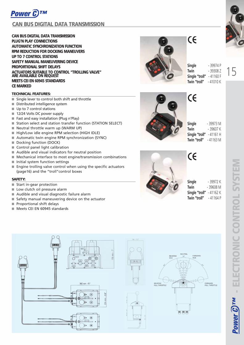
CAN BUS DIGITAL DATA TRANSMISSION
TECHNICAL FEATURES:■ Single lever to control both shift and throttle■ Distributed intelligence system■ Up to 7 control stations■ 12/24 Volts DC power supply■ Fast and easy installation (Plug n’Play)■ Station select and station transfer function (STATION SELECT)■ Neutral throttle warm up (WARM UP)■ High/Low idle engine RPM selection (HIGH IDLE)■ Automatic twin engine RPM synchronization (SYNC)■ Docking function (DOCK)■ Control panel light calibration■ Audible and visual indicators for neutral position■ Mechanical interface to most engine/transmission combinations■ Initial system function settings■ Engine trolling valve control when using the specific actuators
(page16) and the “troll”control boxes
SAFETY:■ Start in-gear protection■ Low clutch oil pressure alarm■ Audible and visual diagnostic failure alarm■ Safety manual maneuvering device on the actuator ■ Proportional shift delays■ Meets CEI EN 60945 standards
Single - 39974 PTwin - 39308 ZSingle “troll” - 41160 FTwin “troll” - 41010 K
Single - 39973 MTwin - 39607 KSingle “troll” - 41161 H Twin “troll” - 41163 M
Single - 39972 KTwin - 39608 MSingle “troll” - 41162 KTwin “troll” - 41164 P
CAN BUS DIGITAL DATA TRANSMISSIONPLUG’N PLAY CONNECTIONSAUTOMATIC SYNCHRONIZATION FUNCTIONRPM REDUCTION FOR DOCKING MANEUVERSUP TO 7 CONTROL STATIONSSAFETY MANUAL MANEUVERING DEVICEPROPORTIONAL SHIFT DELAYSACTUATORS SUITABLE TO CONTROL “TROLLING VALVE” ARE AVAILABLE ON REQUESTMEETS CEI EN 60945 STANDARDSCE MARKED
- ELE
CTRO
NIC
CO
NTR
OL
SYST
EM
ULTRAFLEX2010-Ita:ULTRAFLEX2009-Ita.qxd 18/09/09 17:02 Pagina 15
16
Pow
er C
™Po
wer
C™
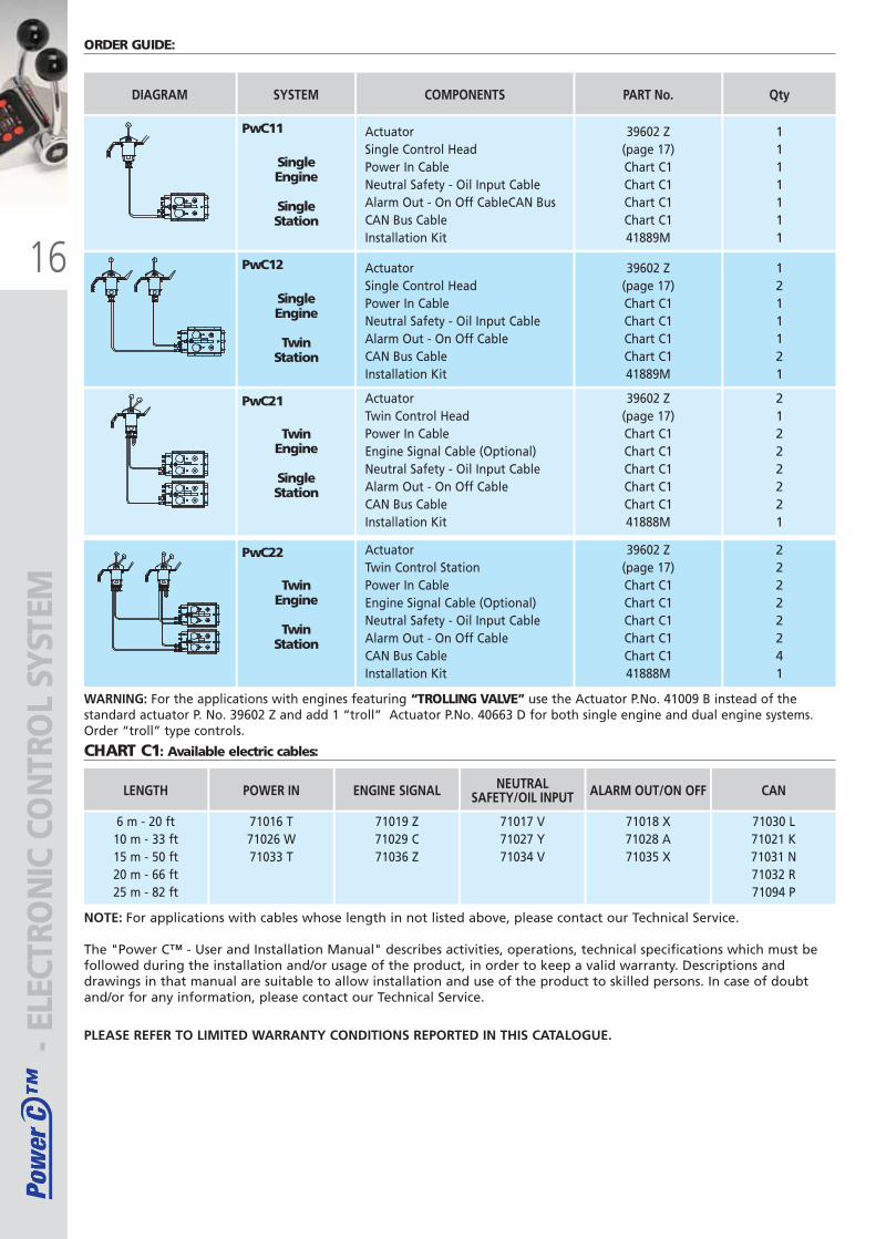
ORDER GUIDE:
NOTE: For applications with cables whose length in not listed above, please contact our Technical Service.
WARNING: For the applications with engines featuring “TROLLING VALVE” use the Actuator P.No. 41009 B instead of thestandard actuator P. No. 39602 Z and add 1 “troll” Actuator P.No. 40663 D for both single engine and dual engine systems.Order “troll” type controls.
SingleEngine
SingleStation
SYSTEMDIAGRAM
ActuatorSingle Control HeadPower In CableNeutral Safety - Oil Input CableAlarm Out - On Off CableCAN BusCAN Bus CableInstallation Kit
1111111
QtyCOMPONENTS
6 m - 20 ft10 m - 33 ft15 m - 50 ft20 m - 66 ft25 m - 82 ft
LENGTH
71016 T71026 W71033 T
POWER IN
71019 Z71029 C71036 Z
ENGINE SIGNAL
71017 V71027 Y71034 V
NEUTRALSAFETY/OIL INPUT
71018 X71028 A71035 X
ALARM OUT/ON OFF
71030 L71021 K71031 N71032 R71094 P
CAN
39602 Z(page 17)Chart C1Chart C1Chart C1Chart C141889M
PART No.
TwinEngine
SingleStation
ActuatorTwin Control HeadPower In CableEngine Signal Cable (Optional)Neutral Safety - Oil Input CableAlarm Out - On Off CableCAN Bus CableInstallation Kit
21222221
39602 Z(page 17)Chart C1Chart C1Chart C1Chart C1Chart C141888M
TwinEngine
TwinStation
ActuatorTwin Control StationPower In CableEngine Signal Cable (Optional)Neutral Safety - Oil Input CableAlarm Out - On Off CableCAN Bus CableInstallation Kit
22222241
39602 Z(page 17)Chart C1Chart C1Chart C1Chart C1Chart C141888M
SingleEngine
TwinStation
ActuatorSingle Control HeadPower In CableNeutral Safety - Oil Input CableAlarm Out - On Off CableCAN Bus CableInstallation Kit
1211121
39602 Z(page 17)Chart C1Chart C1Chart C1Chart C141889M
- ELE
CTRO
NIC
CO
NTR
OL
SYST
EM
CHART C1: Available electric cables:
The "Power C™ - User and Installation Manual" describes activities, operations, technical specifications which must befollowed during the installation and/or usage of the product, in order to keep a valid warranty. Descriptions anddrawings in that manual are suitable to allow installation and use of the product to skilled persons. In case of doubtand/or for any information, please contact our Technical Service.
PLEASE REFER TO LIMITED WARRANTY CONDITIONS REPORTED IN THIS CATALOGUE.
PwC11
PwC12
PwC21
PwC22
ULTRAFLEX2010-Ita:ULTRAFLEX2009-Ita.qxd 18/09/09 17:02 Pagina 16
1177
MEC
HA
NIC
AL
STEE
RIN
G S
YSTE
MS
MEC
HA
NIC
AL
STEE
RIN
G S
YSTE
MS
ULTRAFLEX2010-Ita:ULTRAFLEX2009-Ita.qxd 18/09/09 17:02 Pagina 17
2
1
3
18
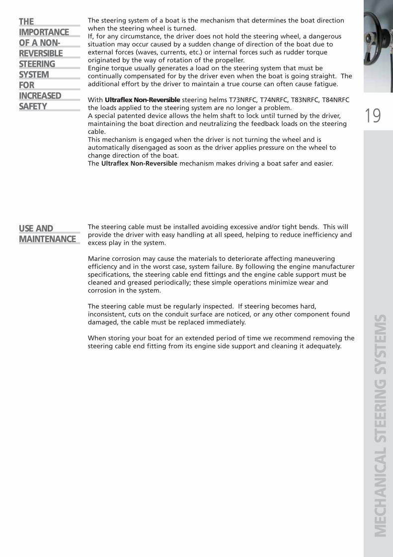
T71FC Planetary gear design steering with M66 (Ultraflex)
T85 Direct transmission steering with M66 (Ultraflex)
Direct transmission steering of well known competitor brand (T)
Direct transmission steering of well known competitor brand (M)
SUGGESTIONSANDWARNINGSWHENSELECTING AMECHANICALSTEERINGSYSTEM
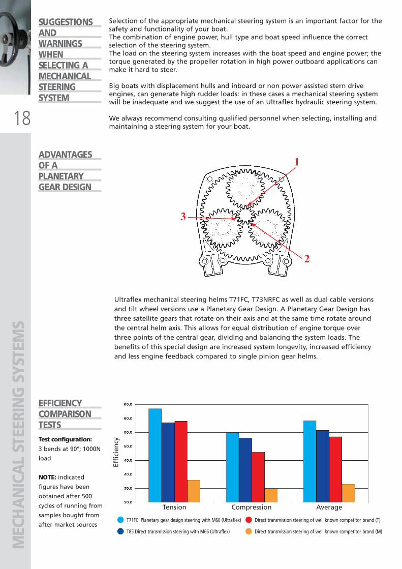
ADVANTAGESOF APLANETARYGEAR DESIGN
EFFICIENCYCOMPARISON TESTS
Selection of the appropriate mechanical steering system is an important factor for thesafety and functionality of your boat.The combination of engine power, hull type and boat speed influence the correctselection of the steering system.The load on the steering system increases with the boat speed and engine power; thetorque generated by the propeller rotation in high power outboard applications canmake it hard to steer.
Big boats with displacement hulls and inboard or non power assisted stern driveengines, can generate high rudder loads: in these cases a mechanical steering systemwill be inadequate and we suggest the use of an Ultraflex hydraulic steering system.
We always recommend consulting qualified personnel when selecting, installing andmaintaining a steering system for your boat.
Ultraflex mechanical steering helms T71FC, T73NRFC as well as dual cable versionsand tilt wheel versions use a Planetary Gear Design. A Planetary Gear Design hasthree satellite gears that rotate on their axis and at the same time rotate aroundthe central helm axis. This allows for equal distribution of engine torque overthree points of the central gear, dividing and balancing the system loads. Thebenefits of this special design are increased system longevity, increased efficiencyand less engine feedback compared to single pinion gear helms.
Effi
cien
cy
Tension Compression Average
Test configuration:
3 bends at 90°; 1000N
load
NOTE: indicated
figures have been
obtained after 500
cycles of running from
samples bought from
after-market sources
MEC
HA
NIC
AL
STEE
RIN
G S
YSTE
MS
ULTRAFLEX2010-Ita:ULTRAFLEX2009-Ita.qxd 18/09/09 17:02 Pagina 18
19
USE AND MAINTENANCE
The steering cable must be installed avoiding excessive and/or tight bends. This willprovide the driver with easy handling at all speed, helping to reduce inefficiency andexcess play in the system.
Marine corrosion may cause the materials to deteriorate affecting maneuveringefficiency and in the worst case, system failure. By following the engine manufacturerspecifications, the steering cable end fittings and the engine cable support must becleaned and greased periodically; these simple operations minimize wear andcorrosion in the system.
The steering cable must be regularly inspected. If steering becomes hard,inconsistent, cuts on the conduit surface are noticed, or any other component founddamaged, the cable must be replaced immediately.
When storing your boat for an extended period of time we recommend removing thesteering cable end fitting from its engine side support and cleaning it adequately.
THE IMPORTANCEOF A NON-REVERSIBLESTEERINGSYSTEMFOR INCREASEDSAFETY
The steering system of a boat is the mechanism that determines the boat directionwhen the steering wheel is turned. If, for any circumstance, the driver does not hold the steering wheel, a dangeroussituation may occur caused by a sudden change of direction of the boat due toexternal forces (waves, currents, etc.) or internal forces such as rudder torqueoriginated by the way of rotation of the propeller.Engine torque usually generates a load on the steering system that must becontinually compensated for by the driver even when the boat is going straight. Theadditional effort by the driver to maintain a true course can often cause fatigue.
With Ultraflex Non-Reversible steering helms T73NRFC, T74NRFC, T83NRFC, T84NRFCthe loads applied to the steering system are no longer a problem.A special patented device allows the helm shaft to lock until turned by the driver,maintaining the boat direction and neutralizing the feedback loads on the steeringcable.This mechanism is engaged when the driver is not turning the wheel and isautomatically disengaged as soon as the driver applies pressure on the wheel tochange direction of the boat.The Ultraflex Non-Reversible mechanism makes driving a boat safer and easier.
MEC
HA
NIC
AL
STEE
RIN
G S
YSTE
MS
ULTRAFLEX2010-Ita:ULTRAFLEX2009-Ita.qxd 18/09/09 17:02 Pagina 19
20
Fig. 1 Fig. 2 Fig. 3
APPLICATION ENGINE POWER STEERING SYSTEM
Twin cable systemsare recommendedfor boats thatexceed 50 mph.Always followenginemanufacturer’sinstructions.
OUTBOARD up to 40 kW (55cv)
BOAT LENGTH
up to 30’ (9m)
T85 - T71FC - T81FC -T73NRFC - T83NRFC - T86
- T88NR - T96 - T98NR
Twin cable rotarysteering systems
up to 35’ (10.5m)
T71FC - T81FC - T73NRFC - T83NRFC - T86
- T88NR - T96 - T98NR
Twin cable rotarysteering systems
TM48 - T67
INBOARD
NOTE: sterndrive engines not equipped with power steering can create very high steering loads. Ourhydraulic steering systems are recommended for these type of boats. For any further informationplease contact our Technical Service Department.
T85 - T71FC - T81FC -T73NRFC - T83NRFC - T86
- T88NR - T96 - T98NR
Twin cable rotarysteering systems
STERNDRIVEPOWER ASSISTED
MEC
HA
NIC
AL
STEE
RIN
G S
YSTE
MS
SELECTIONOFSTEERINGSYSTEMAND CABLELENGTHMEASUREMENT
HOW TOMEASUREFOR NEWSTEERINGCABLEINSTALLATION
TRANSOM SUPPORT OR SPLASHWELL MOUNTING - Fig. 2-3Example (dimensions in cm):A (50) + B (250) + C (80) = 380 - 20 for two 90° bends = 360:30,5 = 11,8 ft; round off to 12 ft
TILT TUBE MOUNTING - Fig. 1Example (dimensions in cm):A (50) + B (250) + C (80) = 380 -20 for two 90° bends = 360 + 30,5For a thru-tube installation390,5 cm : 30,5 = 12,8 ft;round off to 13 ft
Add. A + B + C and subtract 10 cm(4”) for each 90° bend in the cable.For installation through the enginetilt tube, add 30,5 cm (1 ft) to themeasure calculated above.To order in foot length, divide by30,5 and round off to next wholefoot.
■ Speed, hull, horsepower, engine type,displacement and size are major factors inboat performance and handling cha-racteristics. The above selection guideshould be used as a general reference only.
■ One of the major factors in selecting asteering system is proper cable length.Due to specific routing in each boat, these
approximate lengths will vary. Final selectionshould be made with the assistance of aqualified technician.
■ Ultraflex mechanical steering systemsshould not be used on boats equipped withengines that exceed the maximumhorsepower rating of the boat.
ULTRAFLEX2010-Ita:ULTRAFLEX2009-Ita.qxd 18/09/09 17:02 Pagina 20
21
MEC
HA
NIC
AL
STEE
RIN
G S
YSTE
MS
M58
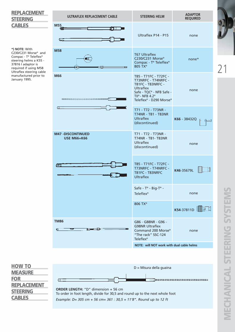
REPLACEMENTSTEERINGCABLES
HOW TOMEASUREFORREPLACEMENTSTEERINGCABLES
STEERING HELMULTRAFLEX REPLACEMENT CABLE ADAPTORREQUIRED
T67 UltraflexC230/C231 Morse®
Compac - T® Teleflex®
805 TX®
none*
*) NOTE: WithC230/C231 Morse® andCompac - T® Teleflex®
steering helms a K55 -37816 I adaptor isrequired if using M58Ultraflex steering cablemanufactured prior toJanuary 1995.
T85 - T71FC - T72FC -T73NRFC - T74NRFC -T81FC - T83NRFC -UltraflexSafe - TQC® - NFB Safe -TII® - NFB 4.2®
Teleflex® - D290 Morse®
T71 - T72 - T73NR -T74NR - T81 - T83NR Ultraflex(discontinued)
M66
none
K66 - 38432Q
T71 - T72 - T73NR -T74NR - T81- T83NR Ultraflex(discontinued)
T85 - T71FC - T72FC -T73NRFC - T74NRFC -T81FC - T83NRFCUltraflex
Safe - T® - Big-T® -
Teleflex®
806 TX®
M47 -DISCONTINUEDUSE M66+K66
none
K46-35679L
none
K54-37811D
ORDER LENGTH: “D” dimension + 56 cmTo order in foot length, divide for 30,5 and round up to the next whole foot
Example: D= 305 cm + 56 cm= 361 : 30,5 = 11’8”. Round up to 12 ft
D = Misura della guaina
TM86
NOTE: will NOT work with dual cable helms
G86 - G88NR - G96 -G98NR UltraflexCommand 200 Morse®
“The rack” SSC-124Teleflex®
none
Ultraflex P14 - P15
M55
none
ULTRAFLEX2010-Ita:ULTRAFLEX2009-Ita.qxd 18/09/09 17:02 Pagina 21
22
G16
MEC
HA
NIC
AL
STEE
RIN
G S
YSTE
MS
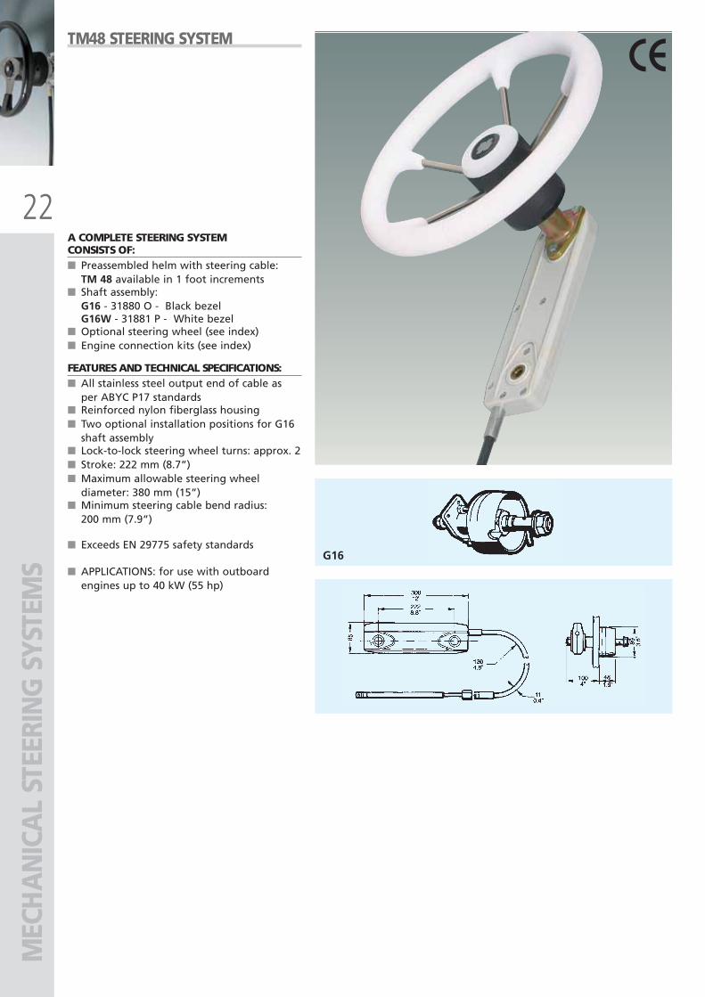
A COMPLETE STEERING SYSTEMCONSISTS OF:■ Preassembled helm with steering cable:
TM 48 available in 1 foot increments■ Shaft assembly:
G16 - 31880 O - Black bezelG16W - 31881 P - White bezel
■ Optional steering wheel (see index)■ Engine connection kits (see index)
FEATURES AND TECHNICAL SPECIFICATIONS:■ All stainless steel output end of cable as
per ABYC P17 standards■ Reinforced nylon fiberglass housing■ Two optional installation positions for G16
shaft assembly■ Lock-to-lock steering wheel turns: approx. 2■ Stroke: 222 mm (8.7”)■ Maximum allowable steering wheel
diameter: 380 mm (15”)■ Minimum steering cable bend radius:
200 mm (7.9”)
■ Exceeds EN 29775 safety standards
■ APPLICATIONS: for use with outboardengines up to 40 kW (55 hp)
TM48 STEERING SYSTEM
ULTRAFLEX2010-Ita:ULTRAFLEX2009-Ita.qxd 18/09/09 17:02 Pagina 22
23
M58
T67 T67W
MEC
HA
NIC
AL
STEE
RIN
G S
YSTE
MS
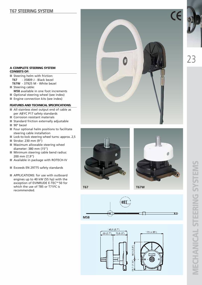
T67 STEERING SYSTEM
A COMPLETE STEERING SYSTEMCONSISTS OF:■ Steering helm with friction:
T67 - 35809 J - Black bezelT67W - 37925 M - White bezel
■ Steering cable:M58 available in one foot increments
■ Optional steering wheel (see index)■ Engine connection kits (see index)
FEATURES AND TECHNICAL SPECIFICATIONS:■ All stainless steel output end of cable as
per ABYC P17 safety standards■ Corrosion resistant materials■ Standard friction externally adjustable■ 90° bezel■ Four optional helm positions to facilitate
steering cable installation■ Lock-to-lock steering wheel turns: approx. 2,5■ Stroke: 230 mm (9”)■ Maximum allowable steering wheel
diameter: 380 mm (15”)■ Minimum steering cable bend radius:
200 mm (7,9”)■ Available in package with ROTECH-IV
■ Exceeds EN 29775 safety standards
■ APPLICATIONS: for use with outboardengines up to 40 kW (55 hp) with theexception of EVINRUDE E-TECTM 50 forwhich the use of T85 or T71FC isrecommended.
ULTRAFLEX2010-Ita:ULTRAFLEX2009-Ita.qxd 18/09/09 17:02 Pagina 23
24
T85
T85
T85W
M66
MEC
HA
NIC
AL
STEE
RIN
G S
YSTE
MS
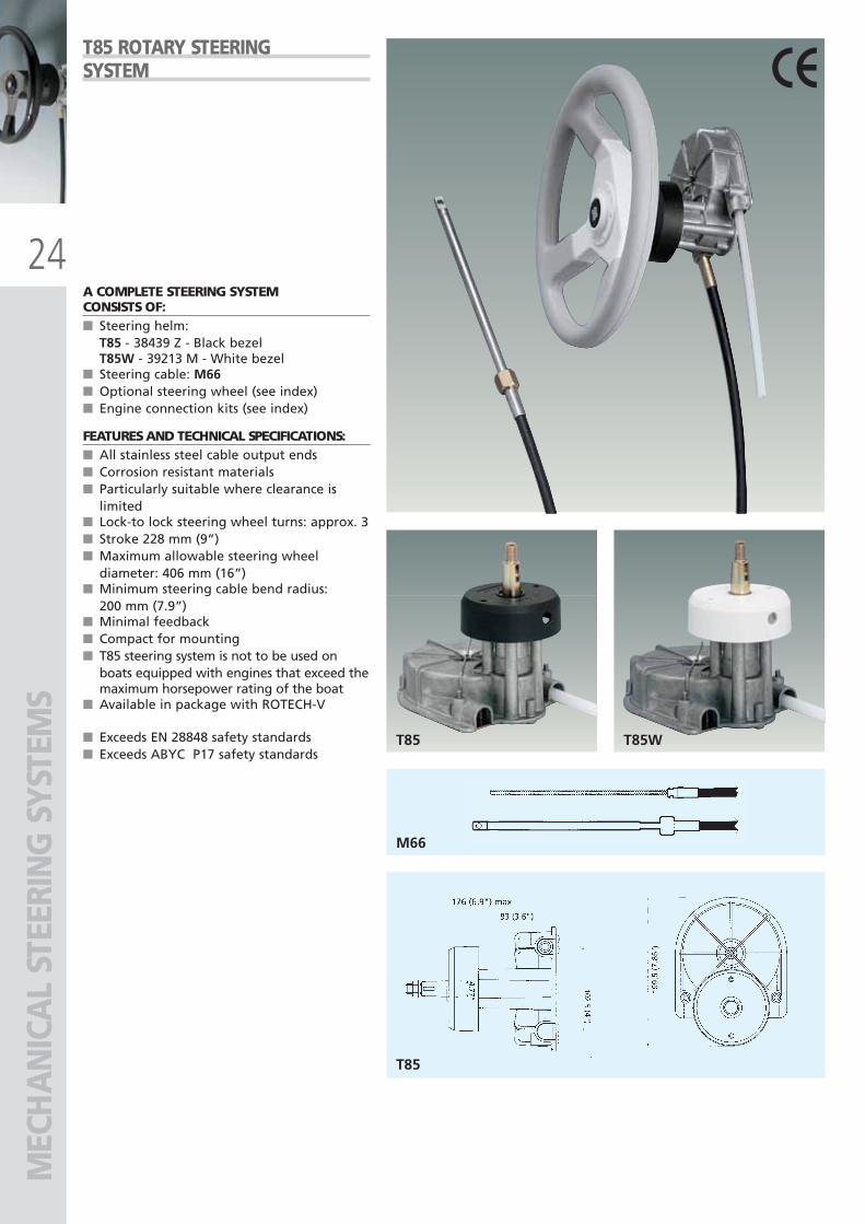
A COMPLETE STEERING SYSTEMCONSISTS OF:■ Steering helm:
T85 - 38439 Z - Black bezelT85W - 39213 M - White bezel
■ Steering cable: M66■ Optional steering wheel (see index)■ Engine connection kits (see index)
FEATURES AND TECHNICAL SPECIFICATIONS:■ All stainless steel cable output ends■ Corrosion resistant materials■ Particularly suitable where clearance is
limited■ Lock-to lock steering wheel turns: approx. 3■ Stroke 228 mm (9”)■ Maximum allowable steering wheel
diameter: 406 mm (16”)■ Minimum steering cable bend radius:
200 mm (7.9”)■ Minimal feedback■ Compact for mounting■ T85 steering system is not to be used on
boats equipped with engines that exceed themaximum horsepower rating of the boat
■ Available in package with ROTECH-V
■ Exceeds EN 28848 safety standards■ Exceeds ABYC P17 safety standards
T85 ROTARY STEERINGSYSTEM
ULTRAFLEX2010-Ita:ULTRAFLEX2009-Ita.qxd 18/09/09 17:02 Pagina 24
25
T71FC
X35X34X34W
T72FC
M66 MEC
HA
NIC
AL
STEE
RIN
G S
YSTE
MS
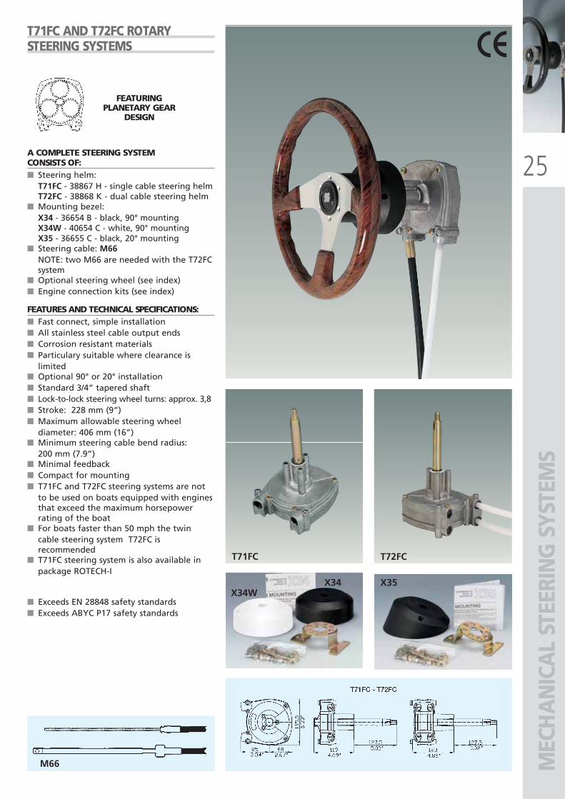
T71FC AND T72FC ROTARYSTEERING SYSTEMS
A COMPLETE STEERING SYSTEMCONSISTS OF:■ Steering helm:
T71FC - 38867 H - single cable steering helmT72FC - 38868 K - dual cable steering helm
■ Mounting bezel:X34 - 36654 B - black, 90° mountingX34W - 40654 C - white, 90° mounting X35 - 36655 C - black, 20° mounting
■ Steering cable: M66NOTE: two M66 are needed with the T72FCsystem
■ Optional steering wheel (see index)■ Engine connection kits (see index)
FEATURES AND TECHNICAL SPECIFICATIONS:■ Fast connect, simple installation ■ All stainless steel cable output ends ■ Corrosion resistant materials■ Particulary suitable where clearance is
limited■ Optional 90° or 20° installation■ Standard 3/4” tapered shaft■ Lock-to-lock steering wheel turns: approx. 3,8■ Stroke: 228 mm (9”)■ Maximum allowable steering wheel
diameter: 406 mm (16”)■ Minimum steering cable bend radius:
200 mm (7.9”)■ Minimal feedback■ Compact for mounting■ T71FC and T72FC steering systems are not
to be used on boats equipped with enginesthat exceed the maximum horsepowerrating of the boat
■ For boats faster than 50 mph the twincable steering system T72FC isrecommended
■ T71FC steering system is also available inpackage ROTECH-I
■ Exceeds EN 28848 safety standards■ Exceeds ABYC P17 safety standards
FEATURINGPLANETARY GEAR
DESIGN
ULTRAFLEX2010-Ita:ULTRAFLEX2009-Ita.qxd 18/09/09 17:02 Pagina 25
26
T73NRFC
X35
T74NRFC
X34X34W
M66MEC
HA
NIC
AL
STEE
RIN
G S
YSTE
MS
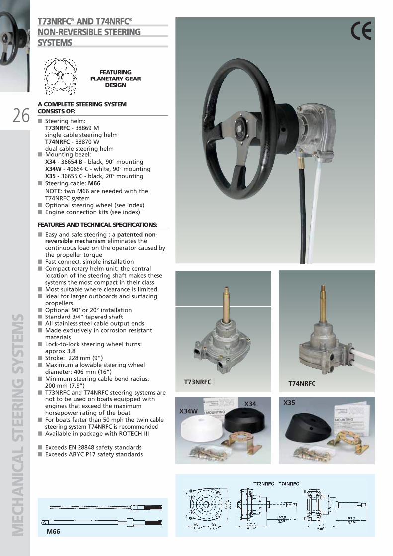
T73NRFC® AND T74NRFC®
NON-REVERSIBLE STEERINGSYSTEMS
A COMPLETE STEERING SYSTEMCONSISTS OF:
■ Steering helm: T73NRFC - 38869 Msingle cable steering helmT74NRFC - 38870 Wdual cable steering helm
■ Mounting bezel:X34 - 36654 B - black, 90° mountingX34W - 40654 C - white, 90° mounting X35 - 36655 C - black, 20° mounting
■ Steering cable: M66NOTE: two M66 are needed with theT74NRFC system
■ Optional steering wheel (see index)■ Engine connection kits (see index)
FEATURES AND TECHNICAL SPECIFICATIONS:
■ Easy and safe steering : a patented non-reversible mechanism eliminates thecontinuous load on the operator caused bythe propeller torque
■ Fast connect, simple installation ■ Compact rotary helm unit: the central
location of the steering shaft makes thesesystems the most compact in their class
■ Most suitable where clearance is limited■ Ideal for larger outboards and surfacing
propellers■ Optional 90° or 20° installation■ Standard 3/4” tapered shaft■ All stainless steel cable output ends■ Made exclusively in corrosion resistant
materials■ Lock-to-lock steering wheel turns:
approx 3,8■ Stroke: 228 mm (9”)■ Maximum allowable steering wheel
diameter: 406 mm (16”) ■ Minimum steering cable bend radius:
200 mm (7.9”)■ T73NRFC and T74NRFC steering systems are
not to be used on boats equipped withengines that exceed the maximumhorsepower rating of the boat
■ For boats faster than 50 mph the twin cablesteering system T74NRFC is recommended
■ Available in package with ROTECH-III
■ Exceeds EN 28848 safety standards■ Exceeds ABYC P17 safety standards
FEATURINGPLANETARY GEAR
DESIGN
ULTRAFLEX2010-Ita:ULTRAFLEX2009-Ita.qxd 18/09/09 17:02 Pagina 26
27
X52
M66M
ECH
AN
ICA
L ST
EERI
NG
SYS
TEM
S
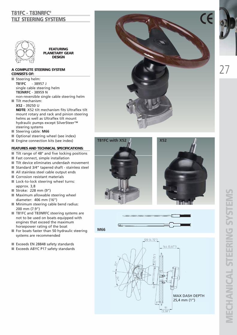
T81FC - T83NRFC®
TILT STEERING SYSTEMS
A COMPLETE STEERING SYSTEMCONSISTS OF:■ Steering helm:
T81FC - 38957 Jsingle cable steering helmT83NRFC - 38959 Nnon-reversible single cable steering helm
■ Tilt mechanism: X52 - 39250 UNOTE: X52 tilt mechanism fits Ultraflex tiltmount rotary and rack and pinion steeringhelms as well as Ultraflex tilt mounthydraulic pumps except SilverSteer™steering systems
■ Steering cable: M66■ Optional steering wheel (see index)■ Engine connection kits (see index)
FEATURES AND TECHNICAL SPECIFICATIONS:■ Tilt range of 48° and five locking positions■ Fast connect, simple installation■ Tilt device eliminates underdash movement■ Standard 3/4” tapered shaft - stainless steel■ All stainless steel cable output ends ■ Corrosion resistant materials■ Lock-to-lock steering wheel turns:
approx. 3,8■ Stroke: 228 mm (9”)■ Maximum allowable steering wheel
diameter: 406 mm (16”)■ Minimum steering cable bend radius:
200 mm (7.9”)■ T81FC and T83NRFC steering systems are
not to be used on boats equipped withengines that exceed the maximumhorsepower rating of the boat
■ For boats faster than 50 hydraulic steeringsystems are recommended
■ Exceeds EN 28848 safety standards■ Exceeds ABYC P17 safety standards
FEATURINGPLANETARY GEAR
DESIGN
MAX DASH DEPTH25,4 mm (1”)
T81FC with X52
ULTRAFLEX2010-Ita:ULTRAFLEX2009-Ita.qxd 18/09/09 17:02 Pagina 27
28
X35
X34X34W
MEC
HA
NIC
AL
STEE
RIN
G S
YSTE
MS
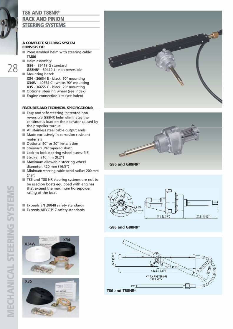
A COMPLETE STEERING SYSTEMCONSISTS OF:■ Preassembled helm with steering cable:
TM86■ Helm assembly:
G86 - 39418 G standardG88NR® - 39419 J - non reversible
■ Mounting bezel:X34 - 36654 B - black, 90° mountingX34W - 40654 C - white, 90° mounting X35 - 36655 C - black, 20° mounting
■ Optional steering wheel (see index)■ Engine connection kits (see index)
FEATURES AND TECHNICAL SPECIFICATIONS:■ Easy and safe steering: patented non
reversible G88NR helm eliminates thecontinuous load on the operator caused bythe propeller torque
■ All stainless steel cable output ends ■ Made exclusively in corrosion resistant
materials■ Optional 90° or 20° installation ■ Standard 3/4”tapered shaft■ Lock-to-lock steering wheel turns: 3,5 ■ Stroke: 210 mm (8.2”) ■ Maximum allowable steering wheel
diameter: 420 mm (16.5”)■ Minimum steering cable bend radius: 200 mm
(7,9”)■ T86 and T88 NR steering systems are not to
be used on boats equipped with enginesthat exceed the maximum horsepowerrating of the boat
■ Exceeds EN 28848 safety standards■ Exceeds ABYC P17 safety standards
T86 AND T88NR®
RACK AND PINIONSTEERING SYSTEMS
G86 and G88NR®
G86 and G88NR®
T86 and T88NR®
ULTRAFLEX2010-Ita:ULTRAFLEX2009-Ita.qxd 18/09/09 17:02 Pagina 28
29
MEC
HA
NIC
AL
STEE
RIN
G S
YSTE
MS
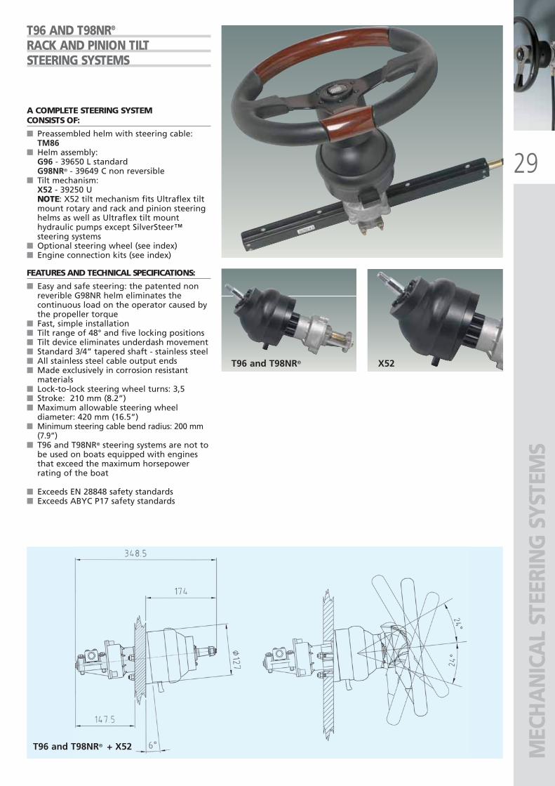
A COMPLETE STEERING SYSTEMCONSISTS OF:
■ Preassembled helm with steering cable:TM86
■ Helm assembly:G96 - 39650 L standardG98NR® - 39649 C non reversible
■ Tilt mechanism:X52 - 39250 UNOTE: X52 tilt mechanism fits Ultraflex tiltmount rotary and rack and pinion steeringhelms as well as Ultraflex tilt mounthydraulic pumps except SilverSteer™steering systems
■ Optional steering wheel (see index)■ Engine connection kits (see index)
FEATURES AND TECHNICAL SPECIFICATIONS:
■ Easy and safe steering: the patented nonreverible G98NR helm eliminates thecontinuous load on the operator caused bythe propeller torque
■ Fast, simple installation■ Tilt range of 48° and five locking positions■ Tilt device eliminates underdash movement■ Standard 3/4” tapered shaft - stainless steel■ All stainless steel cable output ends ■ Made exclusively in corrosion resistant
materials■ Lock-to-lock steering wheel turns: 3,5 ■ Stroke: 210 mm (8.2”)■ Maximum allowable steering wheel
diameter: 420 mm (16.5”)■ Minimum steering cable bend radius: 200 mm
(7.9”)■ T96 and T98NR® steering systems are not to
be used on boats equipped with enginesthat exceed the maximum horsepowerrating of the boat
■ Exceeds EN 28848 safety standards■ Exceeds ABYC P17 safety standards
T96 AND T98NR®
RACK AND PINION TILTSTEERING SYSTEMS
T96 and T98NR® + X52
T96 and T98NR® X52
ULTRAFLEX2010-Ita:ULTRAFLEX2009-Ita.qxd 18/09/09 17:02 Pagina 29
30
M55
P14 - P15
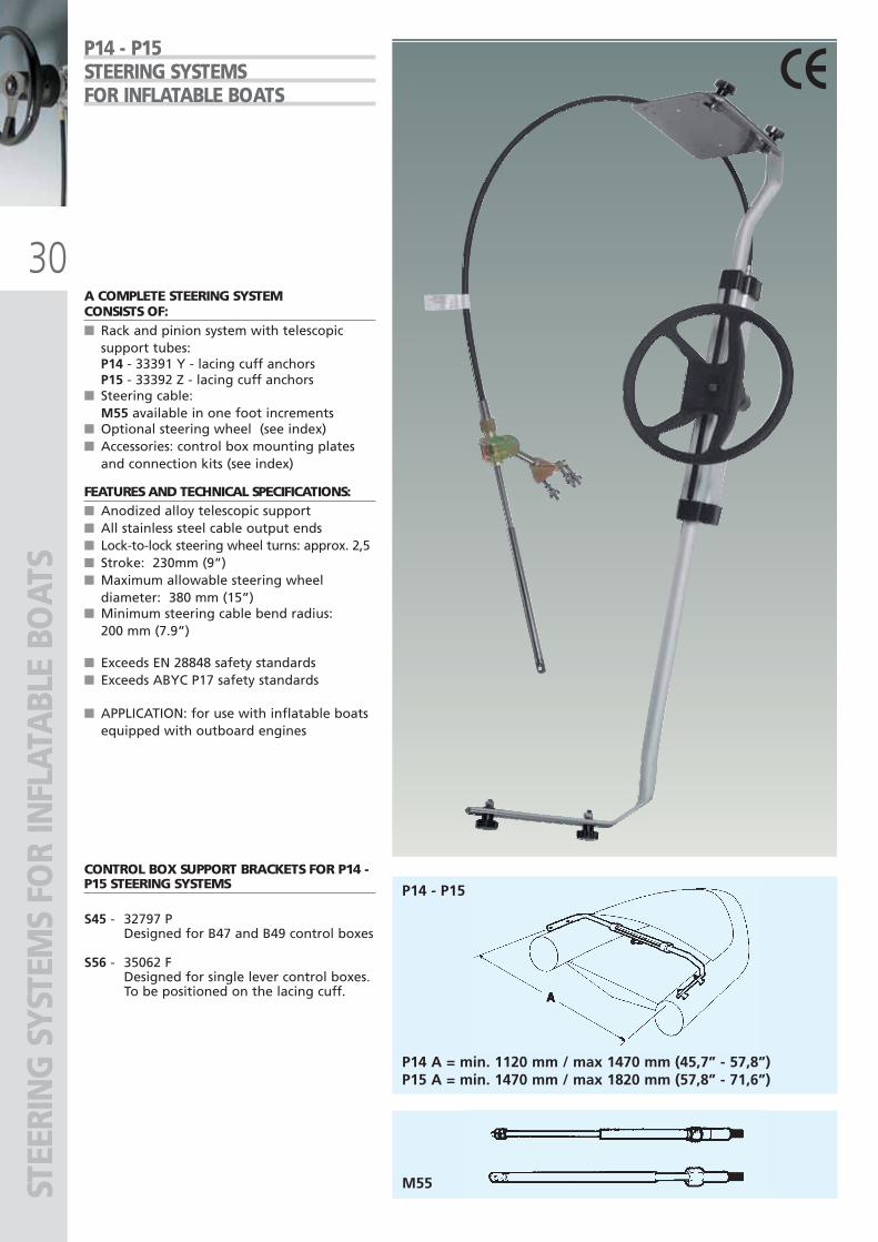
P14 A = min. 1120 mm / max 1470 mm (45,7” - 57,8”)P15 A = min. 1470 mm / max 1820 mm (57,8” - 71,6”)
STEE
RIN
G S
YSTE
MS
FOR
INFL
ATA
BLE
BOAT
SP14 - P15STEERING SYSTEMSFOR INFLATABLE BOATS
A COMPLETE STEERING SYSTEMCONSISTS OF:■ Rack and pinion system with telescopic
support tubes:P14 - 33391 Y - lacing cuff anchorsP15 - 33392 Z - lacing cuff anchors
■ Steering cable:M55 available in one foot increments
■ Optional steering wheel (see index)■ Accessories: control box mounting plates
and connection kits (see index)
FEATURES AND TECHNICAL SPECIFICATIONS:■ Anodized alloy telescopic support■ All stainless steel cable output ends■ Lock-to-lock steering wheel turns: approx. 2,5■ Stroke: 230mm (9”)■ Maximum allowable steering wheel
diameter: 380 mm (15”)■ Minimum steering cable bend radius:
200 mm (7.9”)
■ Exceeds EN 28848 safety standards■ Exceeds ABYC P17 safety standards
■ APPLICATION: for use with inflatable boatsequipped with outboard engines
CONTROL BOX SUPPORT BRACKETS FOR P14 -P15 STEERING SYSTEMS
S45 - 32797 PDesigned for B47 and B49 control boxes
S56 - 35062 FDesigned for single lever control boxes.To be positioned on the lacing cuff.
ULTRAFLEX2010-Ita:ULTRAFLEX2009-Ita.qxd 18/09/09 17:02 Pagina 30
31
T67
M58
STEE
RIN
G S
YST
EMS
FOR
IN
FLA
TAB
LE B
OA
TS
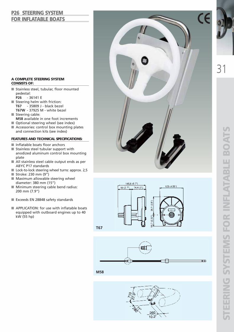
A COMPLETE STEERING SYSTEMCONSISTS OF:
■ Stainless steel, tubular, floor mountedpedestal:P26 - 36141 E
■ Steering helm with friction:T67 - 35809 J - black bezelT67W - 37925 M - white bezel
■ Steering cable:M58 available in one foot increments
■ Optional steering wheel (see index)■ Accessories: control box mounting plates
and connection kits (see index)
FEATURES AND TECHNICAL SPECIFICATIONS:
■ Inflatable boats floor anchors■ Stainless steel tubular support with
anodized aluminum control box mountingplate
■ All stainless steel cable output ends as perABYC P17 standards
■ Lock-to-lock steering wheel turns: approx. 2,5■ Stroke: 230 mm (9”)■ Maximum allowable steering wheel
diameter: 380 mm (15”)■ Minimum steering cable bend radius:
200 mm (7.9”)
■ Exceeds EN 28848 safety standards
■ APPLICATION: for use with inflatable boatsequipped with outboard engines up to 40kW (55 hp)
P26 STEERING SYSTEMFOR INFLATABLE BOATS
ULTRAFLEX2010-Ita:ULTRAFLEX2009-Ita.qxd 18/09/09 17:02 Pagina 31
32
S40
A50
S61
A73SS/A74SS - INOX A75
S55S39
S62
55 mm117 mm
283 mm
283 mm
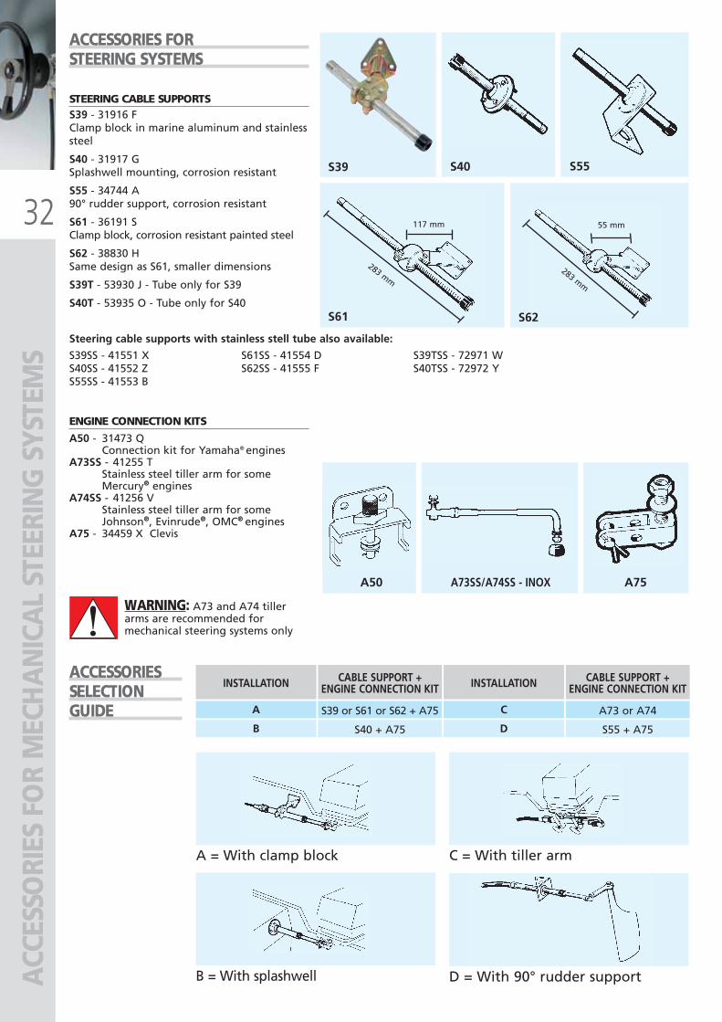
A = With clamp block C = With tiller arm
D = With 90° rudder supportB = With splashwell
INSTALLATION CABLE SUPPORT +ENGINE CONNECTION KIT INSTALLATION CABLE SUPPORT +
ENGINE CONNECTION KIT
A S39 or S61 or S62 + A75
B S40 + A75
C A73 or A74
D S55 + A75
ACC
ESSO
RIES
FO
R M
ECH
AN
ICA
L ST
EERI
NG
SYS
TEM
S
STEERING CABLE SUPPORTSS39 - 31916 FClamp block in marine aluminum and stainlesssteel
S40 - 31917 GSplashwell mounting, corrosion resistant
S55 - 34744 A90° rudder support, corrosion resistant
S61 - 36191 SClamp block, corrosion resistant painted steel
S62 - 38830 HSame design as S61, smaller dimensions
S39T - 53930 J - Tube only for S39
S40T - 53935 O - Tube only for S40
ENGINE CONNECTION KITS
A50 - 31473 QConnection kit for Yamaha® engines
A73SS - 41255 TStainless steel tiller arm for some Mercury® engines
A74SS - 41256 VStainless steel tiller arm for some Johnson®, Evinrude®, OMC® engines
A75 - 34459 X Clevis
ACCESSORIES FORSTEERING SYSTEMS
ACCESSORIESSELECTIONGUIDE
WARNING: A73 and A74 tillerarms are recommended formechanical steering systems only
Steering cable supports with stainless stell tube also available:
S39SS - 41551 X S61SS - 41554 D S39TSS - 72971 WS40SS - 41552 Z S62SS - 41555 F S40TSS - 72972 YS55SS - 41553 B
ULTRAFLEX2010-Ita:ULTRAFLEX2009-Ita.qxd 21/09/09 16:20 Pagina 32
33
R1 B
R1 W
R1 G R2 G R3 G
R2 W R3 W R4 W
R2 B R3 B R4 B
A 88
A 92
ACC
ESSO
RIES
FO
R M
ECH
AN
ICA
L ST
EERI
NG
SYS
TEM
S
WIRE TYPE STEERINGGROMMETS AND RINGS
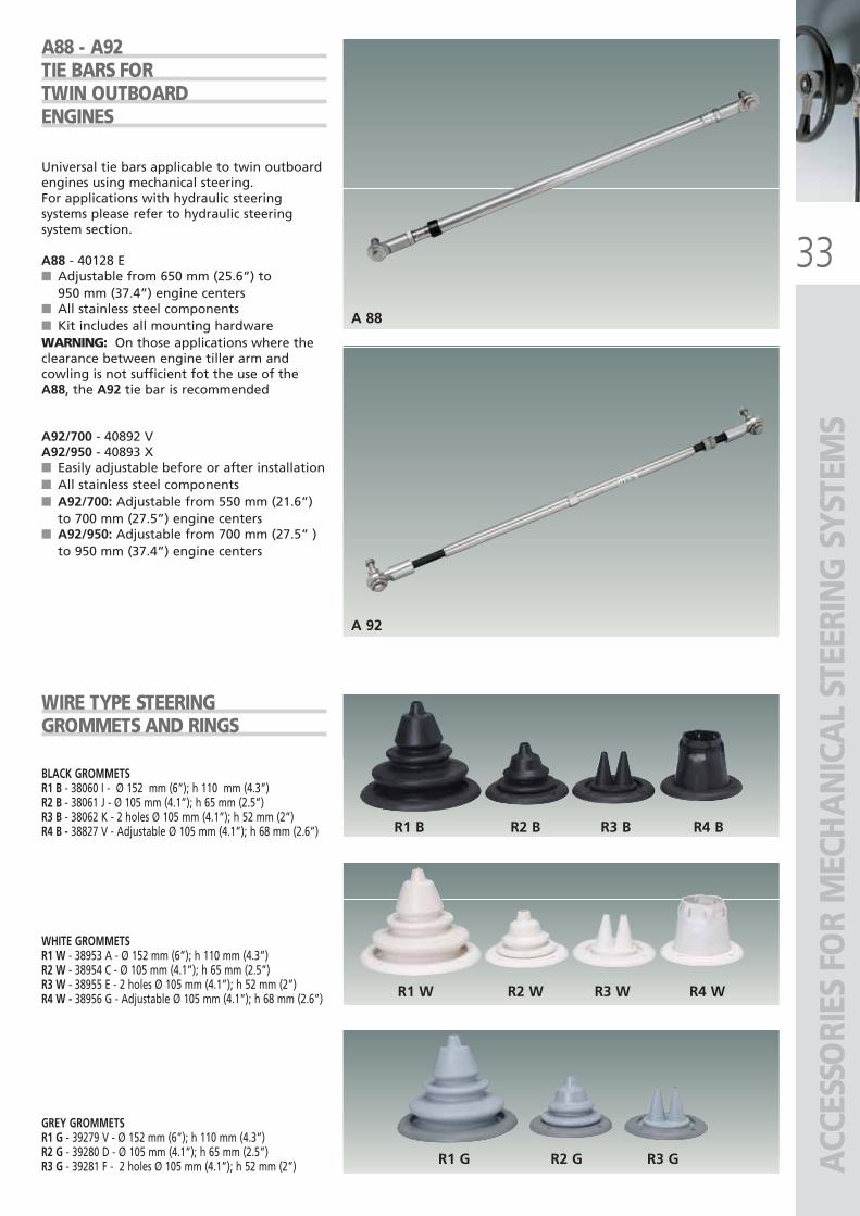
A88 - A92TIE BARS FOR TWIN OUTBOARD ENGINES
BLACK GROMMETSR1 B - 38060 I - Ø 152 mm (6”); h 110 mm (4.3”)R2 B - 38061 J - Ø 105 mm (4.1”); h 65 mm (2.5”)R3 B - 38062 K - 2 holes Ø 105 mm (4.1”); h 52 mm (2”)R4 B - 38827 V - Adjustable Ø 105 mm (4.1”); h 68 mm (2.6”)
WHITE GROMMETSR1 W - 38953 A - Ø 152 mm (6”); h 110 mm (4.3”)R2 W - 38954 C - Ø 105 mm (4.1”); h 65 mm (2.5”)R3 W - 38955 E - 2 holes Ø 105 mm (4.1”); h 52 mm (2”)R4 W - 38956 G - Adjustable Ø 105 mm (4.1”); h 68 mm (2.6”)
GREY GROMMETSR1 G - 39279 V - Ø 152 mm (6”); h 110 mm (4.3”)R2 G - 39280 D - Ø 105 mm (4.1”); h 65 mm (2.5”)R3 G - 39281 F - 2 holes Ø 105 mm (4.1”); h 52 mm (2”)
Universal tie bars applicable to twin outboardengines using mechanical steering. For applications with hydraulic steeringsystems please refer to hydraulic steeringsystem section.
A88 - 40128 E■ Adjustable from 650 mm (25.6”) to
950 mm (37.4”) engine centers■ All stainless steel components■ Kit includes all mounting hardwareWARNING: On those applications where theclearance between engine tiller arm andcowling is not sufficient fot the use of theA88, the A92 tie bar is recommended
A92/700 - 40892 V A92/950 - 40893 X■ Easily adjustable before or after installation■ All stainless steel components■ A92/700: Adjustable from 550 mm (21.6”)
to 700 mm (27.5”) engine centers■ A92/950: Adjustable from 700 mm (27.5” )
to 950 mm (37.4”) engine centers
ULTRAFLEX2010-Ita:ULTRAFLEX2009-Ita.qxd 21/09/09 16:20 Pagina 33
34
ROTECH - I
ROTECH - III
ROTECH - IV
ROTECH - V
PACK
AG
ED M
ECH
AN
ICA
L ST
EERI
NG
SYS
TEM
S
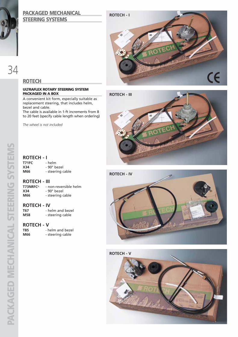
ROTECHULTRAFLEX ROTARY STEERING SYSTEMPACKAGED IN A BOXA convenient kit form, especially suitable asreplacement steering, that includes helm,bezel and cable.The cable is available in 1-ft increments from 8to 20 feet (specify cable length when ordering)
The wheel is not included
PACKAGED MECHANICALSTEERING SYSTEMS
ROTECH - IT71FC - helmX34 - 90° bezelM66 - steering cable
ROTECH - IIIT73NRFC® - non-reversible helmX34 - 90° bezelM66 - steering cable
ROTECH - IVT67 - helm and bezelM58 - steering cable
ROTECH - VT85 - helm and bezelM66 - steering cable
ULTRAFLEX2010-Ita:ULTRAFLEX2009-Ita.qxd 18/09/09 17:02 Pagina 34
3355
HYD
RAU
LIC
STEE
RIN
G S
YSTE
MS
ULTRAFLEX2010-Ita:ULTRAFLEX2009-Ita.qxd 18/09/09 17:03 Pagina 35
36
HYD
RAU
LIC
STEE
RIN
G S
YSTE
MS
- CRO
SS R
EFER
ENCE
SUGGESTION AND WARNINGS WHEN SELECTING A HYDRAULIC STEERING SYSTEM
WARNING: These recommendationsshould be used as a general referenceonly. Final selection should be madewith the assistance of a qualifiedinstallation technician.For any further information pleasecontact our Technical Service
UP39-SVS39cc
-
UP33-SVS33cc
-
UP28-SVS28cc
-
UP4545 cc
-
UP 3939cc
-
UP3333cc
-
UP2828cc
-
UP2525cc
-
UP2020cc
4,7UC94-OBF
----3,13,64,34,8-UC128-OBF
3,13,64,3------UC128-SVS
--------3,4/5,0UC68-OBS
---2,9/3,63,4/4,24,0/4,94,7/5,85,3/6,5-UC132-OBS
---2,93,44,04,75,6-UC133-IOB
--------3,5UC69-I
----3,03,54,14,6-UC116-I
---3,74,35,16,06,7-UC168-I
----5,56,57,78,6-UC215-I
---6,57,58,9---UC293-I
---8,49,7----UC378-I
STEERING WHEEL TURNS single cylinder
SuggestedUP39-SVS39cc
-
UP33-SVS33cc
-
UP4545cc
5,3
UP3939cc
6,2
UP3333cc
7,3
UP2828cc
-UC128-OBF
6,27,3----UC128-SVS
--5,8/7,26,8/8,48,0/9,8-UC132-OBS
--5,86,88,0-UC133-IOB
--5,26,07,08,2UC116-I
--7,48,6--UC168-I
--9,5---UC215-I
STEERING WHEEL TURNS double cylinder
Cylinder modelSingle enginesingle cylinder
Double engine single cylinder
NON counterrotating propellers
Power max hpPower max hp
150
150
300
350
300
UC94-OBF
UC68-OBS
UC128-OBF
UC128-SVS
UC132-OBS
not applicable
not applicable
300
350
300
not applicable
not applicable
500
600
450
not applicable
not applicable
500
600
500
not applicable
not applicable
600
700
600
Power max hp Power max hp Power max hp
counterrotating propellers
Double engine double cylinder
NON counterrotating propellers
counterrotating propellers
OUTBOARD CYLINDERS Maximum power rating applicable
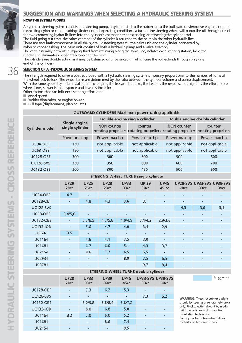
HOW THE SYSTEM WORKS
A hydraulic steering system consists of a steering pump, a cylinder tied to the rudder or to the outboard or sterndrive engine and theconnecting nylon or copper tubing. Under normal operating conditions, a turn of the steering wheel will pump the oil through one ofthe two connecting hydraulic lines into the cylinder’s chamber either extending or retracting the cylinder rod.The fluid going out from the other chamber of the cylinder is returned to the helm via the other hydraulic line.There are two basic components in all the hydraulic steering systems: the helm unit and the cylinder, connected bynylon or copper tubing. The helm unit consists of both a hydraulic pump and a valve assembly.The valve assembly prevents outgoing fluid from returning along the same line, isolates each steering station, locks therudder and eliminates rudder “feedback” to the helm.The cylinders are double acting and may be balanced or unbalanced (in which case the rod extends through only oneend of the cylinder).
SELECTION OF A HYDRAULIC STEERING SYSTEM
The strength required to drive a boat equipped with a hydraulic steering system is inversely proportional to the number of turns ofthe wheel lock-to-lock. The wheel turns are determined by the ratio between the cylinder volume and pump displacement.With the same type of cylinder installed on the engine, the less are the turns, the faster is the response but higher is the effort; morewheel turns, slower is the response and lower is the effort.Other factors that can influence steering effort are:■ Vessel speed■ Rudder dimension, or engine power■ Hull type (displacement, planing, etc.)
ULTRAFLEX2010-Ita:ULTRAFLEX2009-Ita.qxd 18/09/09 17:03 Pagina 36
37
CROSS REFERENCE
HYD
RAU
LIC
STEE
RIN
G S
YSTE
MS
- CRO
SS R
EFER
ENCE
HELM PUMPS
ULTRAFLEX TELEFLEX®
UP20 FUP20 TUP25 F
UP25NV FUP25 TUP28 FUP28 TUP 28 RUP33 F
UP33NV FUP33 TUP33 RUP39 FUP39 TUP39 RUP45 FUP45 TUP45 R
UP45-I RUP28 F-SVSUP28 T-SVSUP33 F-SVSUP33 T-SVSUP39 F-SVSUP39 T-SVS
BayStar™ HH4314BayStar™ HH4315
Seastar™ 1.7 HH5269Seastar™ 1.7 HH5761Seastar™ 1.7 HH5744Seastar™ 1.7 HH5271Seastar™ 1.7 HH5741Seastar™ 1.7 HH5261Seastar™ 2.0 HH5273Seastar™ 2.0 HH5760Seastar™ 2.0 HH5743
-Seastar™ 2.4 HH5272Seastar™ 2.4 HH5742Seastar™ 2.4 HH5262
----
Seastar™ PRO - HH5779Seastar™ PRO - HH5773Seastar™ PRO - HH5770Seastar™ PRO - HH5774Seastar™ PRO - HH5772Seastar™ PRO - HH6189
CYLINDERS
ULTRAFLEX TELEFLEX®
UC94-OBFUC128-OBFUC128-SVS
UC68-OBSUC132-OBS
UC69-IUC116-1UC168-IUC215-IUC293-IUC378-I
Seastar™ HC4645Seastar™ HC5345Seastar™ HC5345
-Seastar™ HC5370
-Seastar™ HC5312Seastar™ HC5318Seastar™ HC5319
--
The above CrossReference chart hasbeen drawn to facilitatea functionalcomparison amongbrands and should beused as generalreference only. For anyfurther informationplease contact ourTechnical Service
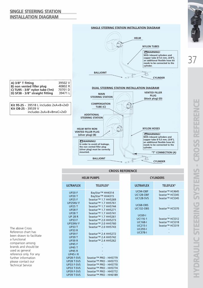
SINGLE STEERING STATIONINSTALLATION DIAGRAM
SINGLE STEERING STATION INSTALLATION DIAGRAM
HELM
NYLON TUBES
BALLJOINT
BALLJOINT
WARNING!
WARNING!
WARNING!
CYLINDER
CYLINDER
With inboard cylinders andcopper tube Ø 9,5 mm, (3/8”),an additional flexible hose kitneeds to be connected to thecylinder.
With inboard cylinders andcopper tube Ø 9,5 mm, (3/8”),an additional flexible hose kitneeds to be connected to thecylinder.
DUAL STEERING STATION INSTALLATION DIAGRAM
MAINSTEERING STATION
COMPENSATIONTUBE (C)
ADDITIONALSTEERING STATION
HELM WITH NON VENTED FILLER PLUG
(silver plug) (B)
In order to avoid oil leakage,the non vented filler plug (silver plug) must be correctlymounted.
VENTED FILLERPLUG
(black plug) (D)
NYLON HOSES
“T” CONNECTION (A)
A) 3/8” T fitting 39502 VB) non vented filler plug 40802 RC) TU95 - 3/8” nylon tube (1m) 70701 DD) SF38 - 3/8” straight fitting 39471 L
Kit 95-2S - 39518 L includes 2xA+B+2xDKit OB-2S - 39539 V
includes 2xA+B+8mxC+2xD
ULTRAFLEX2010-Ita:ULTRAFLEX2009-Ita.qxd 21/09/09 16:21 Pagina 37
38
BubbleBuster™
ZERO EMULSION EFFECTZERO EMULSION EFFECTZERO EMULSION EFFECTZERO EMULSION EFFECT
Bubb
leBu
ster
™
BB BubbleBuster™ - complete set
KBE1 Extension kit
MODEL
41666 R
41682 N
KBD2 Double cylinder purging kit41703 U
KH94 Connection kit for UC94 (not fast connect bleeders)41899 R
KH128 Connection kit for cylinders with old fittings (except UC94)41900 W
PART No. DESCRIPTION
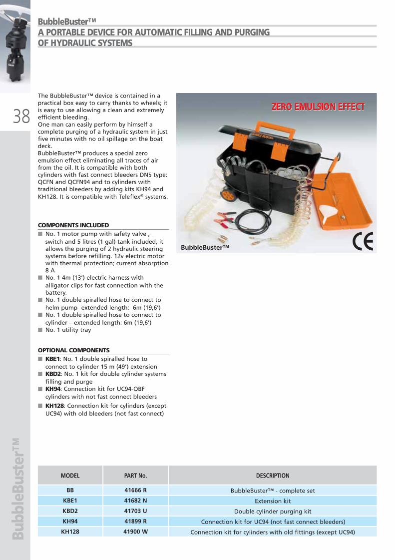
The BubbleBuster™ device is contained in apractical box easy to carry thanks to wheels; itis easy to use allowing a clean and extremelyefficient bleeding.One man can easily perform by himself acomplete purging of a hydraulic system in justfive minutes with no oil spillage on the boatdeck.BubbleBuster™ produces a special zeroemulsion effect eliminating all traces of airfrom the oil. It is compatible with bothcylinders with fast connect bleeders DN5 type:QCFN and QCFN94 and to cylinders withtraditional bleeders by adding kits KH94 andKH128. It is compatible with Teleflex� systems.
BubbleBuster™A PORTABLE DEVICE FOR AUTOMATIC FILLING AND PURGINGOF HYDRAULIC SYSTEMS
COMPONENTS INCLUDED■ No. 1 motor pump with safety valve ,
switch and 5 litres (1 gal) tank included, itallows the purging of 2 hydraulic steeringsystems before refilling. 12v electric motorwith thermal protection; current absorption8 A
■ No. 1 4m (13’) electric harness withalligator clips for fast connection with thebattery.
■ No. 1 double spiralled hose to connect tohelm pump- extended length: 6m (19,6’)
■ No. 1 double spiralled hose to connect tocylinder – extended length: 6m (19,6’)
■ No. 1 utility tray
OPTIONAL COMPONENTS■ KBE1: No. 1 double spiralled hose to
connect to cylinder 15 m (49’) extension ■ KBD2: No. 1 kit for double cylinder systems
filling and purge ■ KH94: Connection kit for UC94-OBF
cylinders with not fast connect bleeders
■ KH128: Connection kit for cylinders (exceptUC94) with old bleeders (not fast connect)
ULTRAFLEX2010-Ita:ULTRAFLEX2009-Ita.qxd 21/09/09 16:21 Pagina 38
39UP20 F
132 mm - 5.2”
X64
132
mm
- 5.
2”
Ø 115 mm - 4.5”
228 mm - 9”
ø 76 mm - 3”
81.3
2m
m- 3
.2”
127 mm - 5”
404 mm - 15.9”
62.2 mm2.5”
108.5 mm4.3”
57 mm2.2” 174 mm
6.8”
ø127 - 5”
135 mm
5”
ø115 mm - 4.5”
ø76 -3”
203 mm - 7.9”
UP20 T + X52
UP20 F + X64
UP20 F DIMENSIONS UP20 T DIMENSIONS
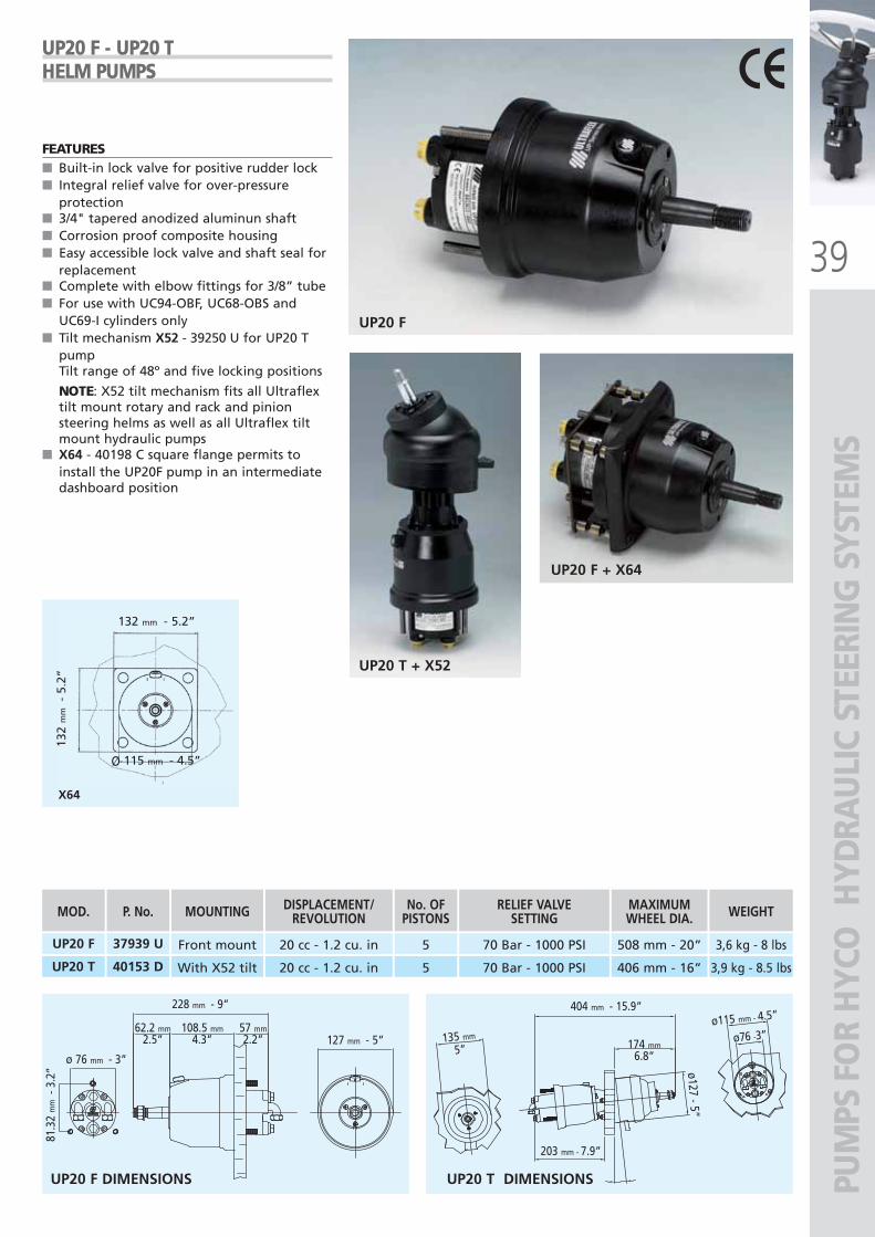
UP20 F Front mount
UP20 T With X52 tilt
20 cc - 1.2 cu. in
20 cc - 1.2 cu. in
5
5
70 Bar - 1000 PSI
70 Bar - 1000 PSI
508 mm - 20”
406 mm - 16”
3,6 kg - 8 lbs
3,9 kg - 8.5 lbs
MOD.
37939 U
40153 D
P. No. MOUNTING DISPLACEMENT/REVOLUTION
No. OFPISTONS
RELIEF VALVE SETTING
MAXIMUMWHEEL DIA. WEIGHT
PUM
PS F
OR
HYC
O H
YDRA
ULI
C ST
EERI
NG
SYS
TEM
S
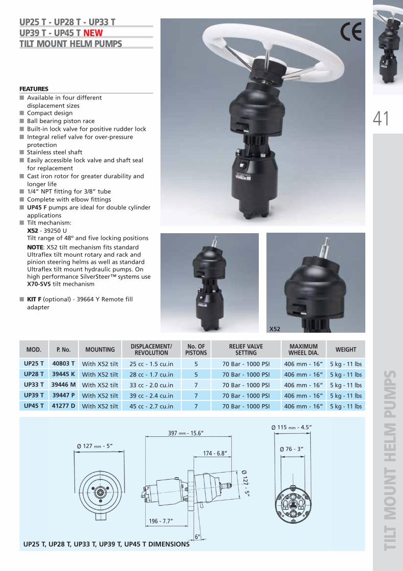
UP20 F - UP20 THELM PUMPS
FEATURES ■ Built-in lock valve for positive rudder lock■ Integral relief valve for over-pressure
protection■ 3/4" tapered anodized aluminun shaft■ Corrosion proof composite housing■ Easy accessible lock valve and shaft seal for
replacement■ Complete with elbow fittings for 3/8” tube■ For use with UC94-OBF, UC68-OBS and
UC69-I cylinders only■ Tilt mechanism X52 - 39250 U for UP20 T
pumpTilt range of 48º and five locking positions
NOTE: X52 tilt mechanism fits all Ultraflextilt mount rotary and rack and pinionsteering helms as well as all Ultraflex tiltmount hydraulic pumps
■ X64 - 40198 C square flange permits toinstall the UP20F pump in an intermediatedashboard position
ULTRAFLEX2010-Ita:ULTRAFLEX2009-Ita.qxd 18/09/09 17:03 Pagina 39
40
Ø 76 mm - 3”Ø 115 mm - 4.5”
55 107 53
2.1” 4.2“ 2”
215 mm - 8.4”
Ø 67 - 2.6”
Ø67
- 2
.6”
132
mm
- 5.
2”
132 mm - 5.2”
Ø 154 mm - 6”
Ø 115 mm - 4.5”X64
X57
UP25 F/28 F/33 F/39 F/45 F + X57UP25 F/28 F/33 F/39 F/45 F + X64
FRO
NT
MO
UN
T H
ELM
PU
MPS
UP25 F, UP25NV F, UP28 F, UP33 F, UP33NV F, UP39 F, UP45 F DIMENSIONS
UP28 F Front mount
UP33 F Front mount
28 cc - 1.7 cu.in
33 cc - 2.0 cu.in
5
7
70 Bar - 1000 PSI
70 Bar - 1000 PSI
710 mm - 28”
710 mm - 28”
5 kg - 11 lbs
5 kg - 11 lbs
MOD.
39443 F
UP25 F Front mount 25 cc - 1.5 cu.in 5 70 Bar - 1000 PSI 710 mm - 28” 5 kg - 11 lbs39618 R
UP25NV F Front mount 25 cc - 1.5 cu.in 5 70 Bar - 1000 PSI 710 mm - 28” 5 kg - 11 lbs41273 V
39422 X
UP33NV F Front mount 33 cc - 2.0 cu.in 7 70 Bar - 1000 PSI 710 mm - 28” 5 kg - 11 lbs41275 Z
UP39 F Front mount 39 cc - 2.4 cu.in 7 70 Bar - 1000 PSI 710 mm - 28” 5 kg - 11 lbs39415 A
UP45 F Front mount 45 cc - 2.7 cu.in 7 70 Bar - 1000 PSI 710 mm - 28” 5 kg - 11 lbs41276 B
P. No. MOUNTING DISPLACEMENT/REVOLUTION
No. OFPISTONS
RELIEF VALVE SETTING
MAXIMUMWHEEL DIA. WEIGHT
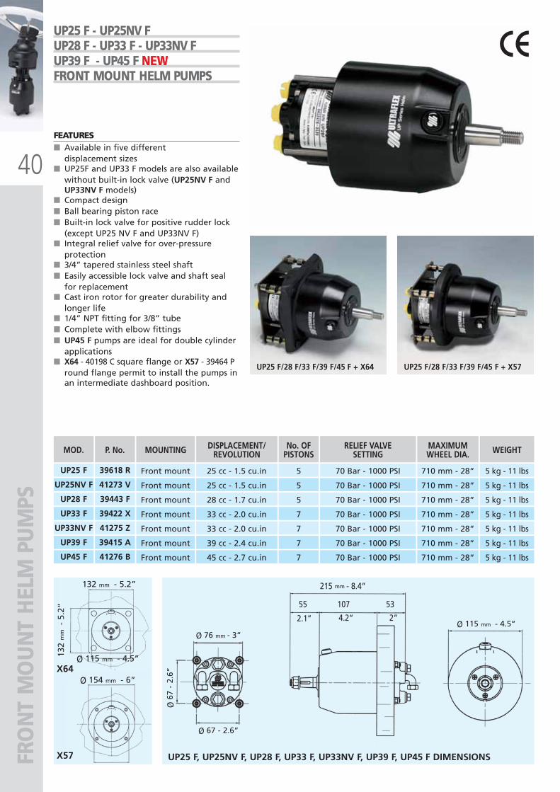
UP25 F - UP25NV F UP28 F - UP33 F - UP33NV F UP39 F - UP45 F NEWNEWNEWFRONT MOUNT HELM PUMPS
FEATURES ■ Available in five different
displacement sizes ■ UP25F and UP33 F models are also available
without built-in lock valve (UP25NV F andUP33NV F models)
■ Compact design■ Ball bearing piston race■ Built-in lock valve for positive rudder lock
(except UP25 NV F and UP33NV F)■ Integral relief valve for over-pressure
protection■ 3/4” tapered stainless steel shaft■ Easily accessible lock valve and shaft seal
for replacement■ Cast iron rotor for greater durability and
longer life■ 1/4” NPT fitting for 3/8” tube■ Complete with elbow fittings■ UP45 F pumps are ideal for double cylinder
applications■ X64 - 40198 C square flange or X57 - 39464 P
round flange permit to install the pumps inan intermediate dashboard position.
ULTRAFLEX2010-Ita:ULTRAFLEX2009-Ita.qxd 18/09/09 17:03 Pagina 40
41
196 - 7.7”
397 mm - 15.6”
174 - 6.8”
6°
Ø127 - 5”
Ø 76 - 3”
Ø 115 mm - 4.5”
Ø 127 mm - 5”
X52
TILT
MO
UN
T H
ELM
PU
MPS
UP28 T With X52 tilt
UP33 T With X52 tilt
28 cc - 1.7 cu.in
33 cc - 2.0 cu.in
5
7
70 Bar - 1000 PSI
70 Bar - 1000 PSI
406 mm - 16”
406 mm - 16”
5 kg - 11 lbs
5 kg - 11 lbs
MOD.
39445 K
UP25 T With X52 tilt 25 cc - 1.5 cu.in 5 70 Bar - 1000 PSI 406 mm - 16” 5 kg - 11 lbs40803 T
39446 M
UP39 T With X52 tilt 39 cc - 2.4 cu.in 7 70 Bar - 1000 PSI 406 mm - 16” 5 kg - 11 lbs39447 P
UP45 T With X52 tilt 45 cc - 2.7 cu.in 7 70 Bar - 1000 PSI 406 mm - 16” 5 kg - 11 lbs41277 D
P. No. MOUNTING DISPLACEMENT/REVOLUTION
No. OFPISTONS
RELIEF VALVE SETTING
MAXIMUMWHEEL DIA. WEIGHT
UP25 T - UP28 T - UP33 TUP39 T - UP45 T NEWNEWNEWTILT MOUNT HELM PUMPS
FEATURES ■ Available in four different
displacement sizes■ Compact design■ Ball bearing piston race■ Built-in lock valve for positive rudder lock■ Integral relief valve for over-pressure
protection■ Stainless steel shaft■ Easily accessible lock valve and shaft seal
for replacement■ Cast iron rotor for greater durability and
longer life■ 1/4” NPT fitting for 3/8” tube■ Complete with elbow fittings■ UP45 F pumps are ideal for double cylinder
applications■ Tilt mechanism:
X52 - 39250 UTilt range of 48º and five locking positions
NOTE: X52 tilt mechanism fits standardUltraflex tilt mount rotary and rack andpinion steering helms as well as standardUltraflex tilt mount hydraulic pumps. Onhigh performance SilverSteer™ systems useX70-SVS tilt mechanism
■ KIT F (optional) - 39664 Y Remote filladapter
UP25 T, UP28 T, UP33 T, UP39 T, UP45 T DIMENSIONS
ULTRAFLEX2010-Ita:ULTRAFLEX2009-Ita.qxd 18/09/09 17:03 Pagina 41
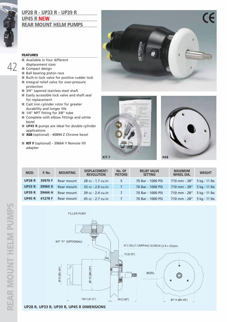
42
X68KIT F
KIT “F” (OPTIONAL)
REA
R M
OU
NT
HEL
M P
UM
PS
UP28 R Rear mount
UP33 R Rear mount
28 cc - 1.7 cu.in
33 cc - 2.0 cu.in
5
7
70 Bar - 1000 PSI
70 Bar - 1000 PSI
710 mm - 28”
710 mm - 28”
5 kg - 11 lbs
5 kg - 11 lbs
MOD.
39970 F
39969 X
UP39 R Rear mount 39 cc - 2.4 cu.in 7 70 Bar - 1000 PSI 710 mm - 28” 5 kg - 11 lbs39444 H
UP45 R Rear mount 45 cc - 2.7 cu.in 7 70 Bar - 1000 PSI 710 mm - 28” 5 kg - 11 lbs41278 F
P. No. MOUNTING DISPLACEMENT/REVOLUTION
No. OFPISTONS
RELIEF VALVESETTING
MAXIMUMWHEEL DIA. WEIGHT
UP28 R - UP33 R - UP39 RUP45 R NEWNEWNEWREAR MOUNT HELM PUMPS
FEATURES■ Available in four different
displacement sizes■ Compact design■ Ball bearing piston race■ Built-in lock valve for positive rudder lock■ Integral relief valve for over-pressure
protection■ 3/4” tapered stainless steel shaft■ Easily accessible lock valve and shaft seal
for replacement■ Cast iron cylinder rotor for greater
durability and longer life■ 1/4” NPT fitting for 3/8” tube■ Complete with elbow fittings and white
bezel■ UP45 R pumps are ideal for double cylinder
applications■ X68 (optional) - 40894 Z Chrome bezel
■ KIT F (optional) - 39664 Y Remote filladapter
UP28 R, UP33 R, UP39 R, UP45 R DIMENSIONS
BEZEL
ULTRAFLEX2010-Ita:ULTRAFLEX2009-Ita.qxd 21/09/09 16:21 Pagina 42
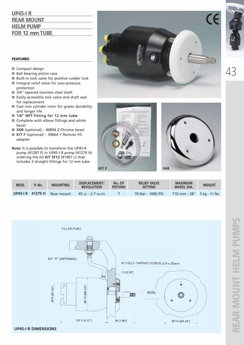
43
KIT F X68
REA
R M
OU
NT
HEL
M P
UM
PS
UP45-I RREAR MOUNTHELM PUMPFOR 12 mm TUBE
FEATURES
■ Compact design■ Ball bearing piston race■ Built-in lock valve for positive rudder lock■ Integral relief valve for over-pressure
protection■ 3/4” tapered stainless steel shaft■ Easily accessible lock valve and shaft seal
for replacement■ Cast iron cylinder rotor for grater durability
and longer life■
■ Complete with elbow fittings and whitebezel
■ (optional) – 40894 Z Chrome bezel■ (optional) – 39664 Y Remote fill
adapter
Note: It is possible to transform the UP45 Rpump (41287 F) in UP45-I R pump (41279 H)ordering the kit KIT SF12 (41907 L) thatincludes 2 straight fittings for 12 mm tube
BEZEL
KIT “F” (OPTIONAL)
UP45-I R DIMENSIONS
UP45-I R Rear mount 45 cc - 2.7 cu.in 7 70 Bar - 1000 PSI 710 mm - 28” 5 kg - 11 lbs
MOD.
41279 H
P. No. MOUNTING DISPLACEMENT/REVOLUTION
No. OFPISTONS
RELIEF VALVESETTING
MAXIMUMWHEEL DIA. WEIGHT
ULTRAFLEX2010-Ita:ULTRAFLEX2009-Ita.qxd 21/09/09 16:21 Pagina 43
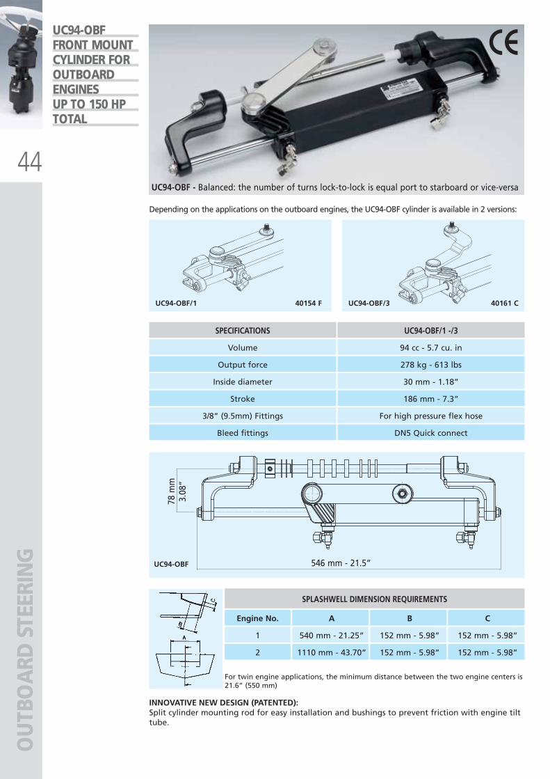
44
UC94-OBF/1 40154 F UC94-OBF/3 40161 C
UC94-OBF 546 mm - 21.5”
78 m
m3.
08”
OU
TBO
ARD
STE
ERIN
G
SPECIFICATIONS UC94-OBF/1 -/3
Volume 94 cc - 5.7 cu. in
Output force 278 kg - 613 lbs
Inside diameter 30 mm - 1.18”
Stroke 186 mm - 7.3”
Bleed fittings DN5 Quick connect
3/8” (9.5mm) Fittings For high pressure flex hose
For twin engine applications, the minimum distance between the two engine centers is21.6” (550 mm)
SPLASHWELL DIMENSION REQUIREMENTS
Engine No.
1
2
A B C
540 mm - 21.25” 152 mm - 5.98” 152 mm - 5.98”
1110 mm - 43.70” 152 mm - 5.98” 152 mm - 5.98”
UC94-OBFFRONT MOUNTCYLINDER FOROUTBOARDENGINESUP TO 150 HPTOTAL
UC94-OBF - Balanced: the number of turns lock-to-lock is equal port to starboard or vice-versa
INNOVATIVE NEW DESIGN (PATENTED):Split cylinder mounting rod for easy installation and bushings to prevent friction with engine tilttube.
Depending on the applications on the outboard engines, the UC94-OBF cylinder is available in 2 versions:
ULTRAFLEX2010-Ita:ULTRAFLEX2009-Ita.qxd 18/09/09 17:03 Pagina 44
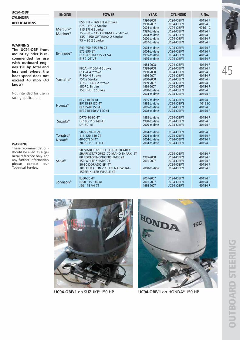
45
OU
TBO
ARD
STE
ERIN
G
UC94-OBFCYLINDERAPPLICATIONS
WARNINGThese recommendationsshould be used as a ge-neral reference only. Forany further informationplease contact ourTechnical Service.
WARNINGThe UC94-OBF frontmount cylinder is re-commended for usewith outboard engi-nes 150 hp total andless and where theboat speed does notexceed 40 mph (40knots)
Not intended for use inracing application
F80A - F100A 4 StrokeF115A 4 StrokeF150A 4 Stroke75C 2 Stroke115C - 130B 2 Stroke150F 2 Stroke150 HPDI 2 Stroke
1984-20081998-20081990-20081996-20072000-20081999-20071999-20072000-to date2004-to date
Yamaha®
F50 EFI – F60 EFI 4 StrokeF75 – F90 4 Stroke115 EFI 4 Stroke75 – 90 – 115 OPTIMAX 2 Stroke135 – 150 OPTIMAX 2 Stroke75 – 90 2 Stroke
Mercury®
Mariner®
40154 F40154 F40154 F40154 F40154 F40154 F40154 F40154 F40154 F
UC94-OBF/1UC94-OBF/1UC94-OBF/1UC94-OBF/1UC94-OBF/1UC94-OBF/1UC94-OBF/1UC94-OBF/1UC94-OBF/1
BF75-BF90 4TBF115-BF130 4TBF135-BF150 4TBF90-BF150 V-TEC 4T
1995-to date1998-to date2005-to date2008-to date
Honda®
40154 F40161C40154 F40154 F
UC94-OBF/1UC94-OBF/3UC94-OBF/1UC94-OBF/1
BJ60-70 4TBJ90-115-140 4TJ90-115 V4 2T
2001-20072001-20071995-2007
Johnson®40154 F40154 F40154 F
UC94-OBF/1UC94-OBF/1UC94-OBF/1
DF70-80-90 4TDF100-115-140 4TDF150 4T
1998-to date1998-to date2006-to date
Suzuki®40154 F40154 F40154 F
UC94-OBF/1UC94-OBF/1UC94-OBF/1
E40-E50-E55-E60 2TE75-E90 2TE115-E130-E135 2T V4E150 2T V6
2004-to date2004-to date1995-to date1995-to date
Evinrude®
40154 F40154 F40154 F40154 F
UC94-OBF/1UC94-OBF/1UC94-OBF/1UC94-OBF/1
50 MADEIRA/ BULL SHARK-60 GREYSHARK/ST.TROPEZ- 70 MAKO SHARK 2T80 PORTOFINO/TIGERSHARK 2T150 WHITE SHARK 2T50-60 DORADO EFI 4T100EFI MARLIN -115 EFI NARWHAL-150EFI KILLER WHALE 4T
1995-20082001-2007
2000-to date
Selva®
40154 F40154 F40154 F40154 F40154 F
UC94-OBF/1UC94-OBF/1UC94-OBF/1UC94-OBF/1UC94-OBF/1
50-60-70-90 2T115-120-140 2T40-50TLDI 4T70-90-115 TLDI 4T
2004-to date2004-to date2004-to date2004-to date
Tohatsu®
Nissan®
40154 F40154 F40154 F40154 F
UC94-OBF/1UC94-OBF/1UC94-OBF/1UC94-OBF/1
40154 F40154 F40161 C40154 F40154 F40154 F40154 F
UC94-OBF/1UC94-OBF/1UC94-OBF/3UC94-OBF/1UC94-OBF/1UC94-OBF/1UC94-OBF/1
1990-20081990-20072004-to date1999-to date2004-to date2000-to date2007-to date
POWERENGINE YEAR CYLINDER P. No.
UC94-OBF/1 on HONDA® 150 HPUC94-OBF/1 on SUZUKI® 150 HP
ULTRAFLEX2010-Ita:ULTRAFLEX2009-Ita.qxd 18/09/09 17:03 Pagina 45
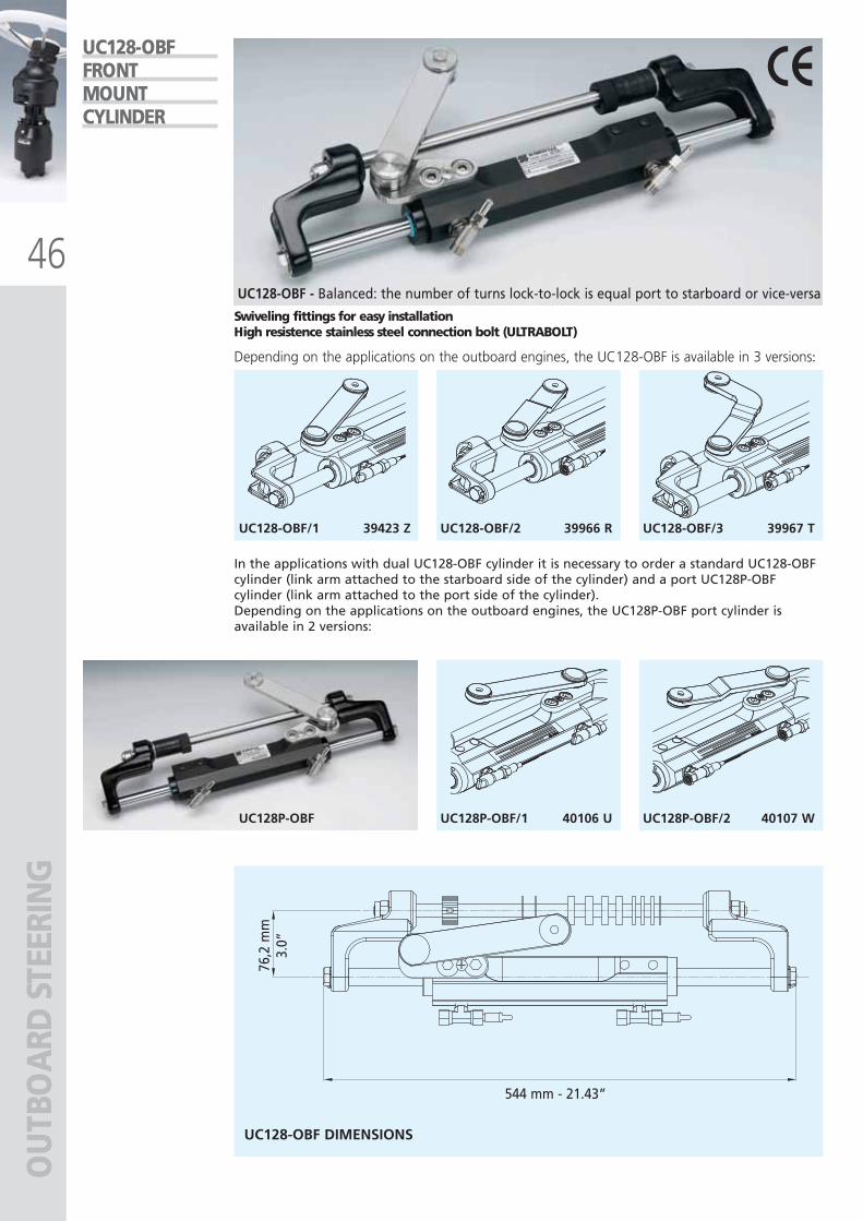
46
UC128-OBF/1 39423 Z UC128-OBF/2 39966 R UC128-OBF/3 39967 T
UC128P-OBF UC128P-OBF/1 40106 U UC128P-OBF/2 40107 W
544 mm - 21.43”
76,2
mm
3.0”
OU
TBO
ARD
STE
ERIN
GUC128-OBFFRONTMOUNTCYLINDER
UC128-OBF - Balanced: the number of turns lock-to-lock is equal port to starboard or vice-versa
In the applications with dual UC128-OBF cylinder it is necessary to order a standard UC128-OBFcylinder (link arm attached to the starboard side of the cylinder) and a port UC128P-OBFcylinder (link arm attached to the port side of the cylinder). Depending on the applications on the outboard engines, the UC128P-OBF port cylinder isavailable in 2 versions:
Swiveling fittings for easy installationHigh resistence stainless steel connection bolt (ULTRABOLT)
Depending on the applications on the outboard engines, the UC128-OBF is available in 3 versions:
UC128-OBF DIMENSIONS
ULTRAFLEX2010-Ita:ULTRAFLEX2009-Ita.qxd 18/09/09 17:03 Pagina 46
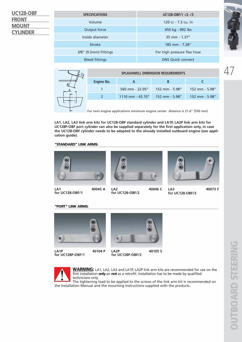
47
OU
TBO
ARD
STE
ERIN
G
SPECIFICATIONS UC128-OBF/1 -/2 -/3
Volume 120 cc - 7.3 cu. in
Output force 450 kg - 992 lbs
Inside diameter 35 mm - 1.37”
Stroke 185 mm - 7.28”
Bleed fittings DN5 Quick connect
3/8” (9.5mm) Fittings For high pressure flex hose
For twin engine applications minimum engine center distance is 21.6” (550 mm)
SPLASHWELL DIMENSION REQUIREMENTS
Engine No.
1
2
A B C
560 mm - 22.05” 152 mm - 5.98” 152 mm - 5.98”
1110 mm - 43.70” 152 mm - 5.98” 152 mm - 5.98”
“STANDARD” LINK ARMS:
“PORT” LINK ARMS:
LA1, LA2, LA3 link arm kits for UC128-OBF standard cylinder and LA1P, LA2P link arm kits forUC128P-OBF port cylinder can also be supplied separately for the first application only, in casethe UC128-OBF cylinder needs to be adapted to the already installed outboard engine (see appli-cation guide).
UC128-OBFFRONTMOUNTCYLINDER
WARNING: LA1, LA2, LA3 and LA1P, LA2P link arm kits are recommended for use on thefirst installation only an not as a retrofit. Installation has to be made by qualifiedtechnicians only.The tightening load to be applied to the screws of the link arm kit is recommended on
the Installation Manual and the mounting instructions supplied with the products.
LA1 40045 Afor UC128-OBF/1
LA2 40046 Cfor UC128-OBF/2
LA3 40073 Ffor UC128-OBF/3
LA1P 40104 Pfor UC128P-OBF/1
LA2P 40105 Sfor UC128P-OBF/2
ULTRAFLEX2010-Ita:ULTRAFLEX2009-Ita.qxd 18/09/09 17:03 Pagina 47
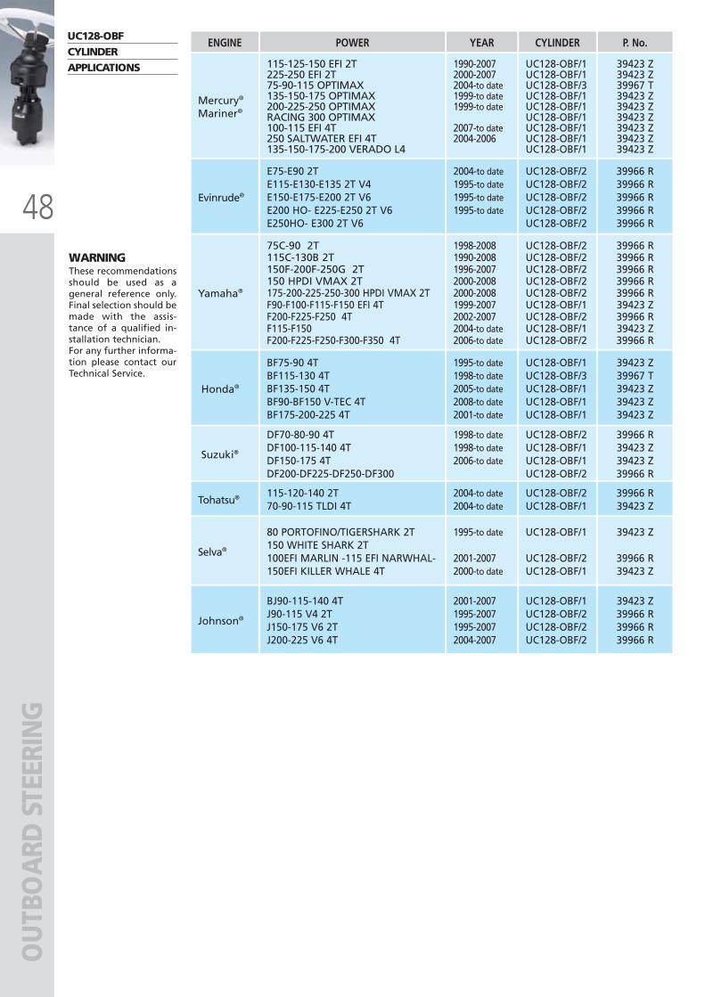
48
OU
TBO
ARD
STE
ERIN
G
WARNINGThese recommendationsshould be used as ageneral reference only.Final selection should bemade with the assis-tance of a qualified in-stallation technician.For any further informa-tion please contact ourTechnical Service.
BJ90-115-140 4TJ90-115 V4 2TJ150-175 V6 2TJ200-225 V6 4T
2001-20071995-20071995-20072004-2007
Johnson®
DF70-80-90 4TDF100-115-140 4TDF150-175 4TDF200-DF225-DF250-DF300
1998-to date1998-to date2006-to date
Suzuki®
E75-E90 2TE115-E130-E135 2T V4E150-E175-E200 2T V6E200 HO- E225-E250 2T V6E250HO- E300 2T V6
2004-to date1995-to date1995-to date1995-to date
Evinrude®
75C-90 2T115C-130B 2T150F-200F-250G 2T150 HPDI VMAX 2T175-200-225-250-300 HPDI VMAX 2TF90-F100-F115-F150 EFI 4TF200-F225-F250 4TF115-F150F200-F225-F250-F300-F350 4T
Yamaha®
UC128-OBFCYLINDERAPPLICATIONS
POWERENGINE
115-125-150 EFI 2T225-250 EFI 2T75-90-115 OPTIMAX135-150-175 OPTIMAX200-225-250 OPTIMAXRACING 300 OPTIMAX100-115 EFI 4T250 SALTWATER EFI 4T135-150-175-200 VERADO L4
YEAR CYLINDER P. No.
Mercury®
Mariner®
1990-20072000-20072004-to date1999-to date1999-to date
2007-to date2004-2006
39423 Z39423 Z39967 T39423 Z39423 Z39423 Z39423 Z39423 Z39423 Z
UC128-OBF/1UC128-OBF/1UC128-OBF/3UC128-OBF/1UC128-OBF/1UC128-OBF/1UC128-OBF/1UC128-OBF/1UC128-OBF/1
BF75-90 4TBF115-130 4TBF135-150 4TBF90-BF150 V-TEC 4TBF175-200-225 4T
1995-to date1998-to date2005-to date2008-to date2001-to date
Honda®
39423 Z39967 T39423 Z39423 Z39423 Z
UC128-OBF/1UC128-OBF/3UC128-OBF/1UC128-OBF/1UC128-OBF/1
39423 Z39966 R39966 R39966 R
UC128-OBF/1UC128-OBF/2UC128-OBF/2UC128-OBF/2
39966 R39423 Z39423 Z39966 R
UC128-OBF/2UC128-OBF/1UC128-OBF/1UC128-OBF/2
39966 R39966 R39966 R39966 R39966 R
UC128-OBF/2UC128-OBF/2UC128-OBF/2UC128-OBF/2UC128-OBF/2
80 PORTOFINO/TIGERSHARK 2T150 WHITE SHARK 2T100EFI MARLIN -115 EFI NARWHAL-150EFI KILLER WHALE 4T
1995-to date
2001-20072000-to date
Selva®
39423 Z
39966 R39423 Z
UC128-OBF/1
UC128-OBF/2UC128-OBF/1
115-120-140 2T70-90-115 TLDI 4T
2004-to date2004-to date
Tohatsu® 39966 R39423 Z
UC128-OBF/2UC128-OBF/1
39966 R39966 R39966 R39966 R39966 R39423 Z39966 R39423 Z39966 R
UC128-OBF/2UC128-OBF/2UC128-OBF/2UC128-OBF/2UC128-OBF/2UC128-OBF/1UC128-OBF/2UC128-OBF/1UC128-OBF/2
1998-20081990-20081996-20072000-20082000-20081999-20072002-20072004-to date2006-to date
ULTRAFLEX2010-Ita:ULTRAFLEX2009-Ita.qxd 18/09/09 17:03 Pagina 48
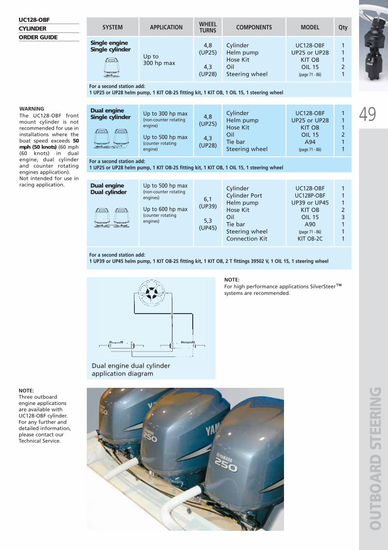
49
OU
TBO
ARD
STE
ERIN
G
Single engine Single cylinder
Dual engineDual cylinder
Dual engineSingle cylinder
11121
Qty
11123111
111211
WARNINGThe UC128-OBF frontmount cylinder is notrecommended for use ininstallations where theboat speed exceeds 50mph (50 knots) (60 mph(60 knots) in dualengine, dual cylinderand counter rotatingengines application).Not intended for use inracing application.
NOTE:Three outboardengine applicationsare available withUC128-OBF cylinder.For any further anddetailed information,please contact ourTechnical Service.
UC128-OBF CYLINDERORDER GUIDE
SYSTEM
CylinderHelm pumpHose KitOilSteering wheel
Up to 300 hp max
UC128-OBFUP25 or UP28
KIT OBOIL 15
(page 71 - 86)
COMPONENTS MODEL
4,8(UP25)
4,3(UP28)
6,1(UP39)
5,3(UP45)
WHEELTURNSAPPLICATION
Up to 500 hp max(non-counter rotatingengines)
Up to 600 hp max(counter rotatingengines)
CylinderCylinder PortHelm pumpHose KitOilTie barSteering wheelConnection Kit
UC128-OBFUC128P-OBF
UP39 or UP45KIT OBOIL 15
A90(page 71 - 86)
KIT OB-2C
For a second station add:1 UP25 or UP28 helm pump, 1 KIT OB-2S fitting kit, 1 KIT OB, 1 OIL 15, 1 steering wheel
Up to 300 hp max(non-counter rotatingengine)
Up to 500 hp max(counter rotating engine)
4,8(UP25)
4,3(UP28)
CylinderHelm pumpHose KitOilTie barSteering wheel
UC128-OBFUP25 or UP28
KIT OBOIL 15
A94(page 71 - 86)
For a second station add:1 UP25 or UP28 helm pump, 1 KIT OB-2S fitting kit, 1 KIT OB, 1 OIL 15, 1 steering wheel
For a second station add:1 UP39 or UP45 helm pump, 1 KIT OB-2S fitting kit, 1 KIT OB, 2 T fittings 39502 V, 1 OIL 15, 1 steering wheel
Dual engine dual cylinder application diagram
NOTE:For high performance applications SilverSteer™systems are recommended.
ULTRAFLEX2010-Ita:ULTRAFLEX2009-Ita.qxd 21/09/09 16:21 Pagina 49
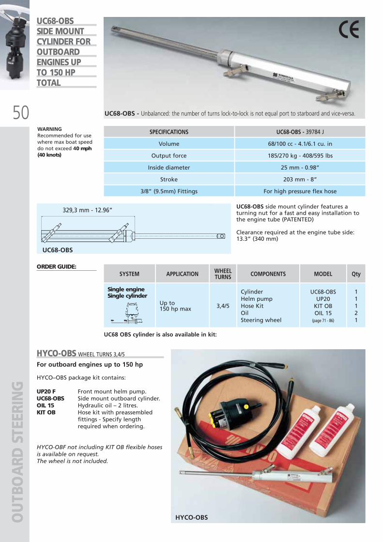
50
329,3 mm - 12.96”
OU
TBO
ARD
STE
ERIN
G
UC68-OBS side mount cylinder features aturning nut for a fast and easy installation tothe engine tube (PATENTED)
Clearance required at the engine tube side:13.3” (340 mm)
SPECIFICATIONS UC68-OBS - 39784 J
Volume 68/100 cc - 4.1/6.1 cu. in
Output force 185/270 kg - 408/595 lbs
Inside diameter 25 mm - 0.98”
Stroke 203 mm - 8”
3/8” (9.5mm) Fittings For high pressure flex hose
UC68-OBS - Unbalanced: the number of turns lock-to-lock is not equal port to starboard and vice-versa.
WARNINGRecommended for usewhere max boat speeddo not exceed 40 mph(40 knots)
UC68-OBS SIDE MOUNT CYLINDER FOROUTBOARD ENGINES UP TO 150 HP TOTAL
ORDER GUIDE:
Single engineSingle cylinder
SYSTEM
CylinderHelm pumpHose KitOilSteering wheel
Up to150 hp max
UC68-OBSUP20
KIT OBOIL 15
(page 71 - 86)
COMPONENTS MODEL
11121
3,4/5
QtyWHEELTURNSAPPLICATION
HYCO-OBS
HYCO-OBS WHEEL TURNS 3,4/5
For outboard engines up to 150 hp
HYCO–OBS package kit contains:
UP20 F Front mount helm pump.UC68-OBS Side mount outboard cylinder.OIL 15 Hydraulic oil – 2 litres.KIT OB Hose kit with preassembled
fittings - Specify lengthrequired when ordering.
HYCO-OBF not including KIT OB flexible hosesis available on request.The wheel is not included.
UC68 OBS cylinder is also available in kit:
UC68-OBS
ULTRAFLEX2010-Ita:ULTRAFLEX2009-Ita.qxd 21/09/09 16:21 Pagina 50
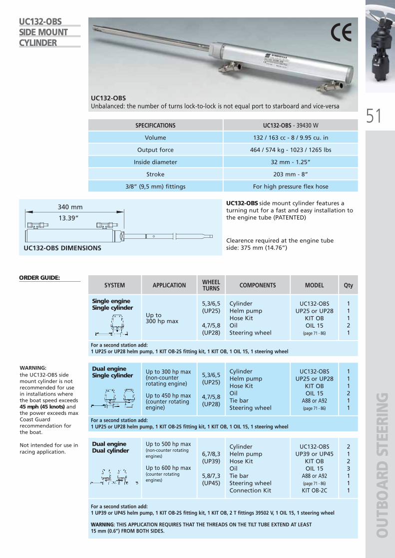
51
OU
TBO
ARD
STE
ERIN
G
UC132-OBSUnbalanced: the number of turns lock-to-lock is not equal port to starboard and vice-versa
UC132-OBSSIDE MOUNT CYLINDER
SPECIFICATIONS UC132-OBS - 39430 W
Output force
Inside diameter
Stroke
3/8” (9,5 mm) fittings For high pressure flex hose
Clearence required at the engine tube side: 375 mm (14.76”)UC132-OBS DIMENSIONS
Volume 132 / 163 cc - 8 / 9.95 cu. in
464 / 574 kg - 1023 / 1265 lbs
32 mm - 1.25”
203 mm - 8”
340 mm
13.39”
UC132-OBS side mount cylinder features aturning nut for a fast and easy installation tothe engine tube (PATENTED)
WARNING:the UC132-OBS sidemount cylinder is notrecommended for usein installations wherethe boat speed exceeds45 mph (45 knots) andthe power exceeds maxCoast Guardrecommendation forthe boat.
Not intended for use inracing application.
ORDER GUIDE:
Single engineSingle cylinder
SYSTEM
CylinderHelm pumpHose KitOilSteering wheel
Up to 300 hp max
UC132-OBSUP25 or UP28
KIT OBOIL 15
(page 71 - 86)
COMPONENTS MODEL
11121
5,3/6,5(UP25)
4,7/5,8(UP28)
6,7/8,3(UP39)
5,8/7,3(UP45)
QtyWHEELTURNSAPPLICATION
Dual engineDual cylinder
Up to 500 hp max(non-counter rotatingengines)
Up to 600 hp max(counter rotatingengines)
CylinderHelm pumpHose KitOilTie barSteering wheelConnection Kit
UC132-OBSUP39 or UP45
KIT OBOIL 15
A88 or A92(page 71 - 86)
KIT OB-2C
2123111
For a second station add:1 UP25 or UP28 helm pump, 1 KIT OB-2S fitting kit, 1 KIT OB, 1 OIL 15, 1 steering wheel
Up to 300 hp max(non-counterrotating engine)
Up to 450 hp max(counter rotating engine)
5,3/6,5(UP25)
4,7/5,8(UP28)
Dual engineSingle cylinder
CylinderHelm pumpHose KitOilTie barSteering wheel
UC132-OBSUP25 or UP28
KIT OBOIL 15
A88 or A92(page 71 - 86)
111211
For a second station add:1 UP25 or UP28 helm pump, 1 KIT OB-2S fitting kit, 1 KIT OB, 1 OIL 15, 1 steering wheel
For a second station add:1 UP39 or UP45 helm pump, 1 KIT OB-2S fitting kit, 1 KIT OB, 2 T fittings 39502 V, 1 OIL 15, 1 steering wheel
: THIS APPLICATION REQUIRES THAT THE THREADS ON THE TILT TUBE EXTEND AT LEAST15 mm (0.6”) FROM BOTH SIDES.
ULTRAFLEX2010-Ita:ULTRAFLEX2009-Ita.qxd 21/09/09 16:21 Pagina 51
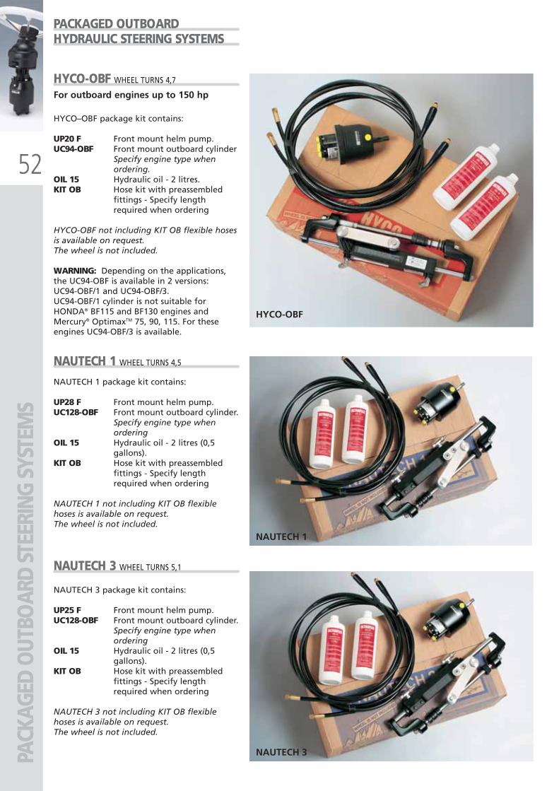
52
HYCO-OBF
NAUTECH 1
NAUTECH 3PACK
AGED
OUT
BOAR
D ST
EERI
NG S
YSTE
MS
PACKAGED OUTBOARDHYDRAULIC STEERING SYSTEMS
HYCO-OBF WHEEL TURNS 4,7
For outboard engines up to 150 hp
HYCO–OBF package kit contains:
UP20 F Front mount helm pump.UC94-OBF Front mount outboard cylinder
Specify engine type whenordering.
OIL 15 Hydraulic oil - 2 litres.KIT OB Hose kit with preassembled
fittings - Specify lengthrequired when ordering
HYCO-OBF not including KIT OB flexible hosesis available on request.The wheel is not included.
WARNING: Depending on the applications,the UC94-OBF is available in 2 versions:UC94-OBF/1 and UC94-OBF/3.UC94-OBF/1 cylinder is not suitable forHONDA® BF115 and BF130 engines andMercury® OptimaxTM 75, 90, 115. For theseengines UC94-OBF/3 is available.
NAUTECH 1 WHEEL TURNS 4,5
NAUTECH 1 package kit contains:
UP28 F Front mount helm pump.UC128-OBF Front mount outboard cylinder.
Specify engine type whenordering
OIL 15 Hydraulic oil - 2 litres (0,5gallons).
KIT OB Hose kit with preassembledfittings - Specify lengthrequired when ordering
NAUTECH 1 not including KIT OB flexiblehoses is available on request. The wheel is not included.
NAUTECH 3 WHEEL TURNS 5,1
NAUTECH 3 package kit contains:
UP25 F Front mount helm pump.UC128-OBF Front mount outboard cylinder.
Specify engine type whenordering
OIL 15 Hydraulic oil - 2 litres (0,5gallons).
KIT OB Hose kit with preassembledfittings - Specify lengthrequired when ordering
NAUTECH 3 not including KIT OB flexiblehoses is available on request. The wheel is not included.
ULTRAFLEX2010-Ita:ULTRAFLEX2009-Ita.qxd 21/09/09 16:22 Pagina 52
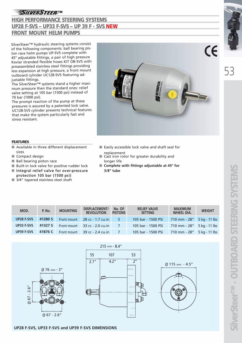
53
Ø 76 mm - 3”Ø 115 mm - 4.5”
55 107 53
2.1” 4.2“ 2”
215 mm - 8.4”
Ø 67 - 2.6”
Ø67
- 2
.6”
UP28 F-SVS Front mount 28 cc - 1.7 cu.in 5 105 bar - 1500 PSi 710 mm - 28” 5 kg - 11 lbs
MOD.
41280 S
UP33 F-SVS Front mount 33 cc - 2.0 cu.in 7 105 bar - 1500 PSi 710 mm - 28” 5 kg - 11 lbs41327 S
UP39 F-SVS Front mount 39 cc - 2.4 cu.in 7 105 bar - 1500 PSi 710 mm - 28” 5 kg - 11 lbs41876 C
P. No. MOUNTING DISPLACEMENT/REVOLUTION
No. OFPISTONS
RELIEF VALVE SETTING
MAXIMUMWHEEL DIA. WEIGHT
■ Easily accessible lock valve and shaft seal for
replacement■ Cast iron rotor for greater durability and
longer life■ Complete with fittings adjustable at 45° for
3/8” tube
FEATURES ■ Available in three different displacement
sizes■ Compact design■ Ball bearing piston race■ Built-in lock valve for positive rudder lock■
■ 3/4” tapered stainless steel shaft
SilverSteer™ hydraulic steering systems consistof the following components: ball bearing pis-ton race helm pumps UP-SVS complete with45° adjustable fittings, a pair of high pressureKevlar stranded flexible hoses KIT OB-SVS withpreassembled stainless steel fittings providingless expansion at high pressure, a front mountoutboard cylinder UC128-SVS featuring ad-justable fittings.The SilverSteer™ systems stand a higher maxi-mum pressure then the standard ones: reliefvalve setting at 105 bar (1500 psi) instead of70 bar (1000 psi).The prompt reaction of the pump at thesepressures is assured by a patented lock valve.UC128-SVS cylinder presents technical featuresthat make the system particularly fast andstress resistant.
-HIGH PERFORMANCE STEERING SYSTEMSUP28 F-SVS – UP33 F-SVS – UP 39 F - SVS NEWNEWNEWFRONT MOUNT HELM PUMPS
Silv
erSt
eer™
- O
UTBO
ARD
STEE
RING
SYS
TEM
S
UP28 F-SVS, UP33 F-SVS and UP39 F-SVS DIMENSIONS
ULTRAFLEX2010-Ita:ULTRAFLEX2009-Ita.qxd 18/09/09 17:03 Pagina 53
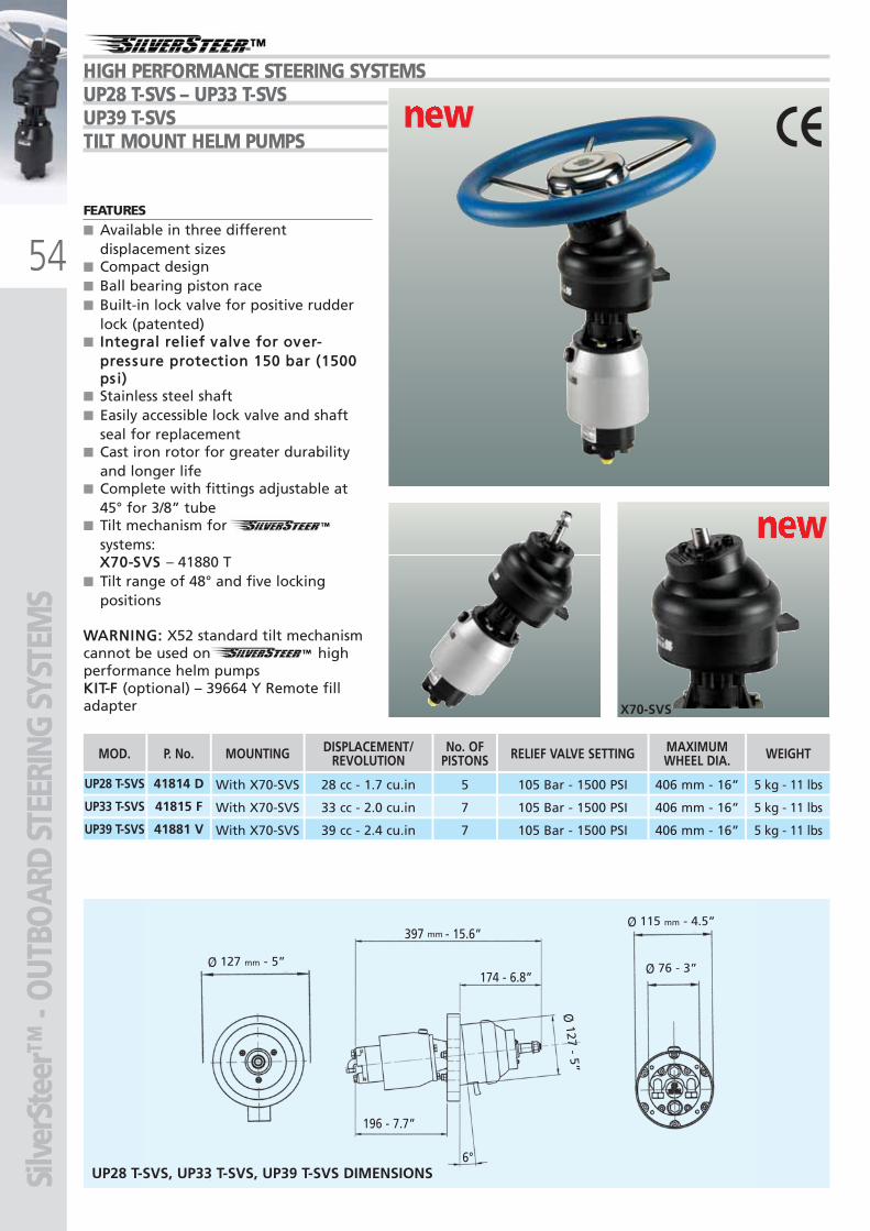
54
-HIGH PERFORMANCE STEERING SYSTEMSUP28 T-SVS – UP33 T-SVSUP39 T-SVSTILT MOUNT HELM PUMPS
new new new new
new new new new
Silv
erSt
eer™
- O
UTBO
ARD
STEE
RING
SYS
TEM
S
196 - 7.7”
397 mm - 15.6”
174 - 6.8”
6°
Ø127 - 5”
Ø 76 - 3”
Ø 115 mm - 4.5”
Ø 127 mm - 5”
UP28 T-SVS, UP33 T-SVS, UP39 T-SVS DIMENSIONS
FEATURES
■ Available in three differentdisplacement sizes
■ Compact design■ Ball bearing piston race■ Built-in lock valve for positive rudder
lock (patented)■
■ Stainless steel shaft■ Easily accessible lock valve and shaft
seal for replacement■ Cast iron rotor for greater durability
and longer life■ Complete with fittings adjustable at
45° for 3/8” tube■ Tilt mechanism for SilverSteer
systems:■ – 41880 T■ Tilt range of 48° and five locking
positions
X52 standard tilt mechanismcannot be used on SilverSteer highperformance helm pumps
(optional) – 39664 Y Remote filladapter X70-SVS
UP28 T-SVS With X70-SVS
UP33 T-SVS With X70-SVS
28 cc - 1.7 cu.in
33 cc - 2.0 cu.in
5
7
105 Bar - 1500 PSI
105 Bar - 1500 PSI
406 mm - 16”
406 mm - 16”
5 kg - 11 lbs
5 kg - 11 lbs
MOD.
41814 D
41815 F
UP39 T-SVS With X70-SVS 39 cc - 2.4 cu.in 7 105 Bar - 1500 PSI 406 mm - 16” 5 kg - 11 lbs41881 V
P. No. MOUNTING DISPLACEMENT/REVOLUTION
No. OFPISTONS RELIEF VALVE SETTING MAXIMUM
WHEEL DIA. WEIGHT
ULTRAFLEX2010-Ita:ULTRAFLEX2009-Ita.qxd 21/09/09 16:22 Pagina 54
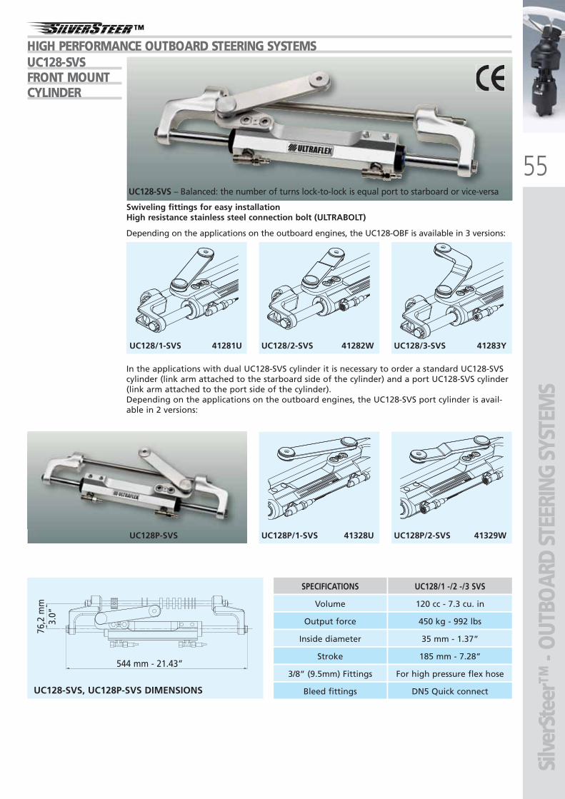
55
HIGH PERFORMANCE OUTBOARD STEERING SYSTEMS
Silv
erSt
eer™
- O
UTBO
ARD
STEE
RING
SYS
TEM
S
UC128/1-SVS 41281U UC128/2-SVS 41282W UC128/3-SVS 41283Y
UC128P-SVS UC128P/1-SVS 41328U UC128P/2-SVS 41329W
UC128-SVS – Balanced: the number of turns lock-to-lock is equal port to starboard or vice-versa
In the applications with dual UC128-SVS cylinder it is necessary to order a standard UC128-SVScylinder (link arm attached to the starboard side of the cylinder) and a port UC128-SVS cylinder(link arm attached to the port side of the cylinder).Depending on the applications on the outboard engines, the UC128-SVS port cylinder is avail-able in 2 versions:
Swiveling fittings for easy installationHigh resistance stainless steel connection bolt (ULTRABOLT)
Depending on the applications on the outboard engines, the UC128-OBF is available in 3 versions:
UC128-SVS, UC128P-SVS DIMENSIONS
544 mm - 21.43”
76,2
mm
3.0”
SPECIFICATIONS UC128/1 -/2 -/3 SVS
Volume 120 cc - 7.3 cu. in
Output force 450 kg - 992 lbs
Inside diameter 35 mm - 1.37”
Stroke 185 mm - 7.28”
Bleed fittings DN5 Quick connect
3/8” (9.5mm) Fittings For high pressure flex hose
UC128-SVSFRONT MOUNTCYLINDER
ULTRAFLEX2010-Ita:ULTRAFLEX2009-Ita.qxd 18/09/09 17:05 Pagina 55
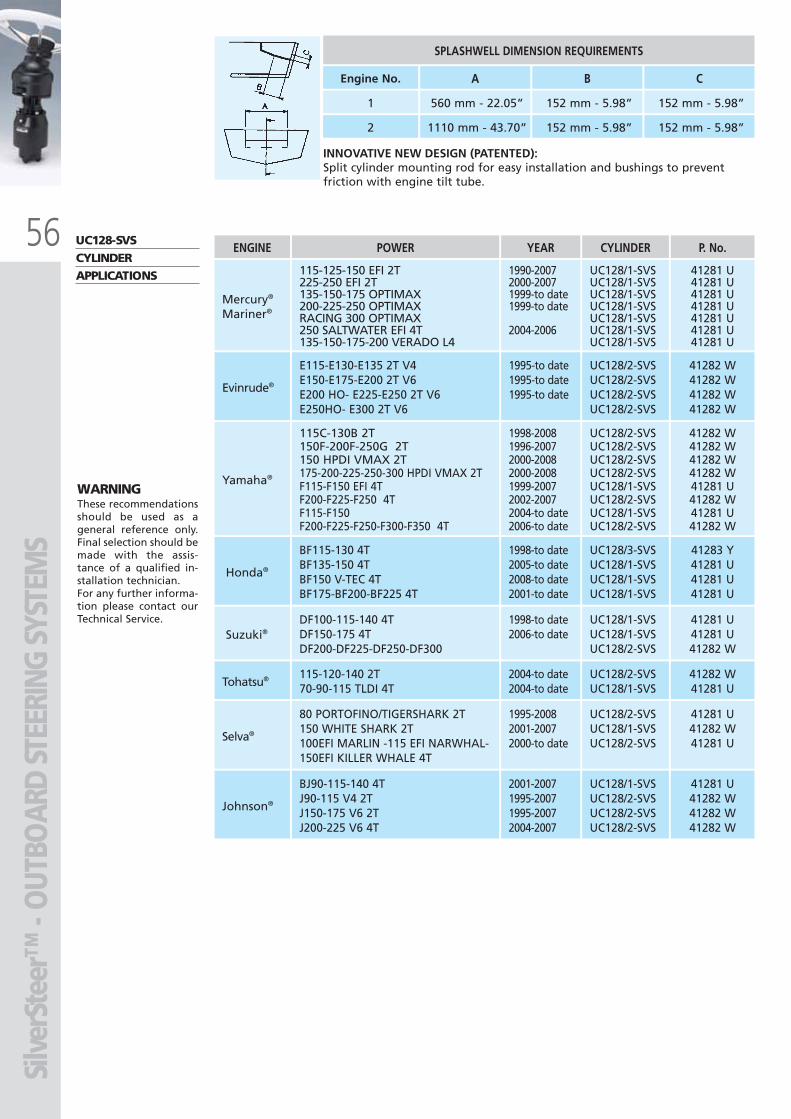
56
Silv
erSt
eer™
- O
UTBO
ARD
STEE
RING
SYS
TEM
S
WARNINGThese recommendationsshould be used as ageneral reference only.Final selection should bemade with the assis-tance of a qualified in-stallation technician.For any further informa-tion please contact ourTechnical Service.
UC128-SVSCYLINDERAPPLICATIONS
INNOVATIVE NEW DESIGN (PATENTED):Split cylinder mounting rod for easy installation and bushings to preventfriction with engine tilt tube.
SPLASHWELL DIMENSION REQUIREMENTS
Engine No.
1
2
A B C
560 mm - 22.05” 152 mm - 5.98” 152 mm - 5.98”
1110 mm - 43.70” 152 mm - 5.98” 152 mm - 5.98”
BJ90-115-140 4TJ90-115 V4 2TJ150-175 V6 2TJ200-225 V6 4T
2001-20071995-20071995-20072004-2007
Johnson®
DF100-115-140 4TDF150-175 4TDF200-DF225-DF250-DF300
1998-to date2006-to dateSuzuki®
E115-E130-E135 2T V4E150-E175-E200 2T V6E200 HO- E225-E250 2T V6E250HO- E300 2T V6
1995-to date1995-to date1995-to dateEvinrude®
115C-130B 2T150F-200F-250G 2T150 HPDI VMAX 2T175-200-225-250-300 HPDI VMAX 2TF115-F150 EFI 4TF200-F225-F250 4TF115-F150F200-F225-F250-F300-F350 4T
Yamaha®
POWERENGINE
115-125-150 EFI 2T225-250 EFI 2T135-150-175 OPTIMAX200-225-250 OPTIMAXRACING 300 OPTIMAX250 SALTWATER EFI 4T135-150-175-200 VERADO L4
YEAR CYLINDER P. No.
Mercury®
Mariner®
1990-20072000-20071999-to date1999-to date
2004-2006
41281 U41281 U41281 U41281 U41281 U41281 U41281 U
UC128/1-SVSUC128/1-SVSUC128/1-SVSUC128/1-SVSUC128/1-SVSUC128/1-SVSUC128/1-SVS
BF115-130 4TBF135-150 4TBF150 V-TEC 4TBF175-BF200-BF225 4T
1998-to date2005-to date2008-to date2001-to date
Honda®
41283 Y41281 U41281 U41281 U
UC128/3-SVSUC128/1-SVSUC128/1-SVSUC128/1-SVS
41281 U41282 W41282 W41282 W
UC128/1-SVSUC128/2-SVSUC128/2-SVSUC128/2-SVS
41281 U41281 U41282 W
UC128/1-SVSUC128/1-SVSUC128/2-SVS
41282 W41282 W41282 W41282 W
UC128/2-SVSUC128/2-SVSUC128/2-SVSUC128/2-SVS
80 PORTOFINO/TIGERSHARK 2T150 WHITE SHARK 2T100EFI MARLIN -115 EFI NARWHAL-150EFI KILLER WHALE 4T
1995-20082001-20072000-to dateSelva®
41281 U41282 W41281 U
UC128/2-SVSUC128/1-SVSUC128/2-SVS
115-120-140 2T70-90-115 TLDI 4T
2004-to date2004-to dateTohatsu® 41282 W
41281 UUC128/2-SVSUC128/1-SVS
41282 W41282 W41282 W41282 W41281 U41282 W41281 U41282 W
UC128/2-SVSUC128/2-SVSUC128/2-SVSUC128/2-SVSUC128/1-SVSUC128/2-SVSUC128/1-SVSUC128/2-SVS
1998-20081996-20072000-20082000-20081999-20072002-20072004-to date2006-to date
ULTRAFLEX2010-Ita:ULTRAFLEX2009-Ita.qxd 18/09/09 17:05 Pagina 56
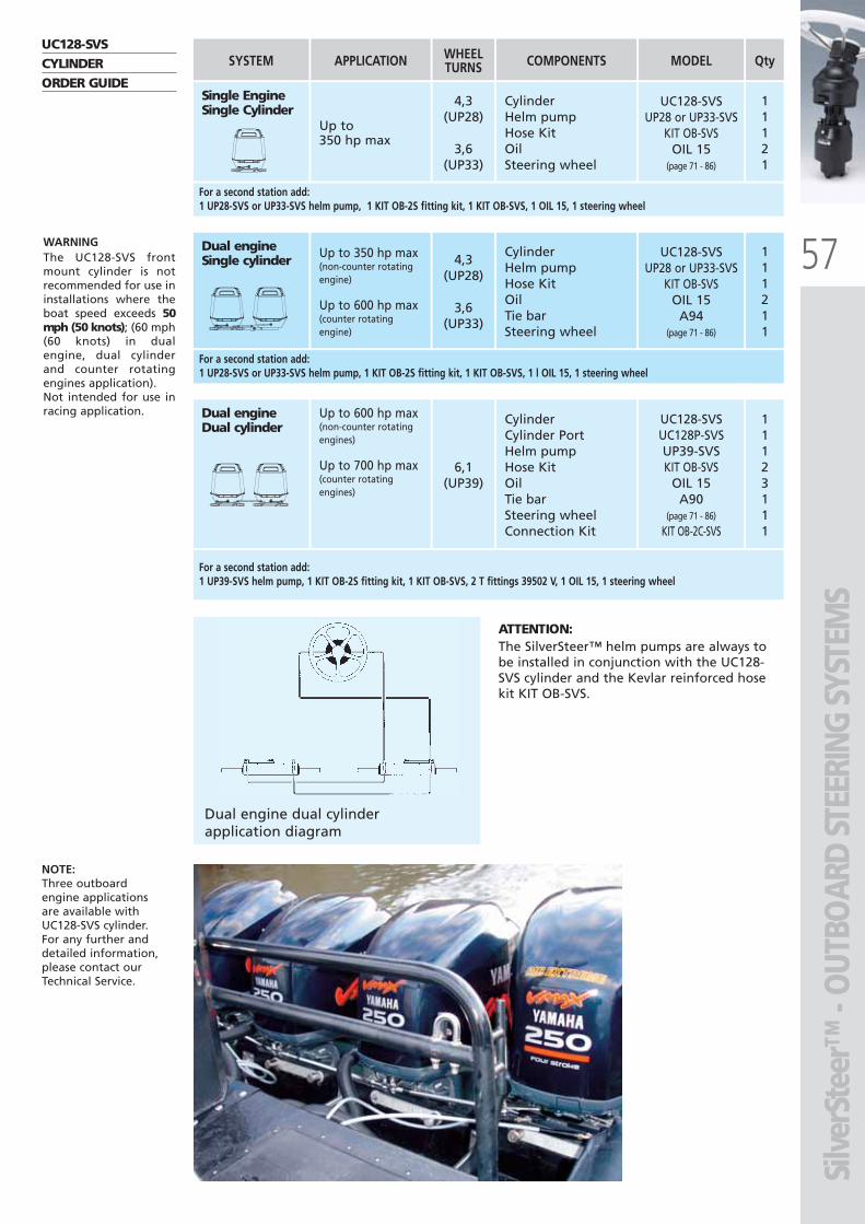
57
Silv
erSt
eer™
- O
UTBO
ARD
STEE
RING
SYS
TEM
S
11121
Qty
11123111
111211
WARNINGThe UC128-SVS frontmount cylinder is notrecommended for use ininstallations where theboat speed exceeds 50mph (50 knots); (60 mph(60 knots) in dualengine, dual cylinderand counter rotatingengines application).Not intended for use inracing application.
NOTE:Three outboardengine applicationsare available withUC128-SVS cylinder.For any further anddetailed information,please contact ourTechnical Service.
UC128-SVSCYLINDERORDER GUIDE
Single Engine Single Cylinder
SYSTEM
CylinderHelm pumpHose KitOilSteering wheel
Up to 350 hp max
UC128-SVSUP28 or UP33-SVS
KIT OB-SVSOIL 15
(page 71 - 86)
COMPONENTS MODEL
4,3(UP28)
3,6(UP33)
6,1(UP39)
WHEELTURNSAPPLICATION
Dual engineDual cylinder
Up to 600 hp max(non-counter rotatingengines)
Up to 700 hp max(counter rotatingengines)
CylinderCylinder PortHelm pumpHose KitOilTie barSteering wheelConnection Kit
UC128-SVSUC128P-SVSUP39-SVSKIT OB-SVS
OIL 15A90
(page 71 - 86)
KIT OB-2C-SVS
For a second station add:1 UP28-SVS or UP33-SVS helm pump, 1 KIT OB-2S fitting kit, 1 KIT OB-SVS, 1 OIL 15, 1 steering wheel
Up to 350 hp max(non-counter rotatingengine)
Up to 600 hp max(counter rotating engine)
4,3(UP28)
3,6(UP33)
Dual engineSingle cylinder
CylinderHelm pumpHose KitOilTie barSteering wheel
UC128-SVSUP28 or UP33-SVS
KIT OB-SVSOIL 15
A94(page 71 - 86)
For a second station add:1 UP28-SVS or UP33-SVS helm pump, 1 KIT OB-2S fitting kit, 1 KIT OB-SVS, 1 l OIL 15, 1 steering wheel
For a second station add:1 UP39-SVS helm pump, 1 KIT OB-2S fitting kit, 1 KIT OB-SVS, 2 T fittings 39502 V, 1 OIL 15, 1 steering wheel
Dual engine dual cylinder application diagram
ATTENTION:The SilverSteer™ helm pumps are always tobe installed in conjunction with the UC128-SVS cylinder and the Kevlar reinforced hosekit KIT OB-SVS.
ULTRAFLEX2010-Ita:ULTRAFLEX2009-Ita.qxd 21/09/09 16:22 Pagina 57
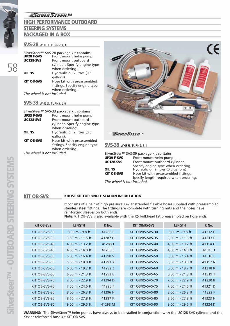
58
Silv
erSt
eer™
- O
UTBO
ARD
STEE
RING
SYS
TEM
S
SVS-28 WHEEL TURNS: 4,3
SilverSteer™ SVS-28 package kit contains:UP28 F-SVS Front mount helm pumpUC128-SVS Front mount outboard
cylinder Specify engine typewhen ordering.
OIL 15 Hydraulic oil 2 litres (0.5gallons).
KIT OB-SVS Hose kit with preassembledfittings. Specify engine typewhen ordering.
The wheel is not included.
SVS-33 WHEEL TURNS: 3,6
SilverSteer™ SVS-33 package kit contains:UP33 F-SVS Front mount helm pumpUC128-SVS Front mount outboard
cylinder Specify engine typewhen ordering.
OIL 15 Hydraulic oil 2 litres (0.5gallons).
KIT OB-SVS Hose kit with preassembledfittings. Specify engine typewhen ordering.
The wheel is not included.
-HIGH PERFORMANCE OUTBOARDSTEERING SYSTEMSPACKAGED IN A BOX
KIT OB-SVS: KHOSE KIT FOR SINGLE STATION INSTALLATION
It consists of a pair of high pressure Kevlar stranded flexible hoses supplied with preassembledstainless steel fittings. The fittings are complete with turning nuts and the hoses havereinforcing sleeves on both ends.Note: KIT OB-SVS is also available with the R5 bulkhead kit preassembled on hose ends.
KIT OB-SVS LENGTH
KIT OB-SVS-30 3,00 m - 9.8 ft
KIT OB-SVS-35 3,50 m - 11.5 ft
KIT OB-SVS-40 4,00 m - 13.2 ft
KIT OB-SVS-45 4,50 m - 14.8 ft
KIT OB-SVS-50 5,00 m - 16.4 ft
KIT OB-SVS-55 5,50 m - 18.0 ft
KIT OB-SVS-60 6,00 m - 19.7 ft
KIT OB-SVS-65 6,50 m - 21.3 ft
KIT OB-SVS-70 7,00 m - 22.9 ft
KIT OB-SVS-75 7,50 m - 24.6 ft
KIT OB-SVS-80 8,00 m - 26.3 ft
KIT OB-SVS-85 8,50 m - 27.8 ft
KIT OB-SVS-90
P. No.
41286 E
41287 G
41288 J
41289 L
41290 V
41291 X
41292 Z
41293 B
41294 D
41295 F
41296 H
41297 K
41298 M 9,00 m - 29.5 ft
KIT OB/R5-SVS LENGTH
KIT OB/R5-SVS-30 3,00 m - 9.8 ft
KIT OB/R5-SVS-35 3,50 m - 11.5 ft
KIT OB/R5-SVS-40 4,00 m - 13.2 ft
KIT OB/R5-SVS-45 4,50 m - 14.8 ft
KIT OB/R5-SVS-50 5,00 m - 16.4 ft
KIT OB/R5-SVS-55 5,50 m - 18.0 ft
KIT OB/R5-SVS-60 6,00 m - 19.7 ft
KIT OB/R5-SVS-65 6,50 m - 21.3 ft
KIT OB/R5-SVS-70 7,00 m - 22.9 ft
KIT OB/R5-SVS-75 7,50 m - 24.6 ft
KIT OB/R5-SVS-80 8,00 m - 26.3 ft
KIT OB/R5-SVS-85 8,50 m - 27.8 ft
KIT OB/R5-SVS-90
P. No.
41312 C
41313 E
41314 G
41315 J
41316 L
41317 N
41318 R
41319 T
41320 B
41321 D
41322 F
41323 H
41324 K9,00 m - 29.5 ft
SVS-39 WHEEL TURNS: 6,1
SilverSteer™ SVS-39 package kit contains:UP39 F-SVS Front mount helm pumpUC128-SVS Front mount outboard cylinder
Specify engine type when orderingOIL 15 Hydraulic oil 2 litres (0.5 gallons).KIT OB-SVS Hose kit with preassembled fittings.
Specify length required when ordering.The wheel is not included.
WARNING: The SilverSteer™ helm pumps have always to be installed in conjunction with the UC128-SVS cylinder and theKevlar reinforced hose kit KIT OB-SVS.
ULTRAFLEX2010-Ita:ULTRAFLEX2009-Ita.qxd 21/09/09 16:22 Pagina 58
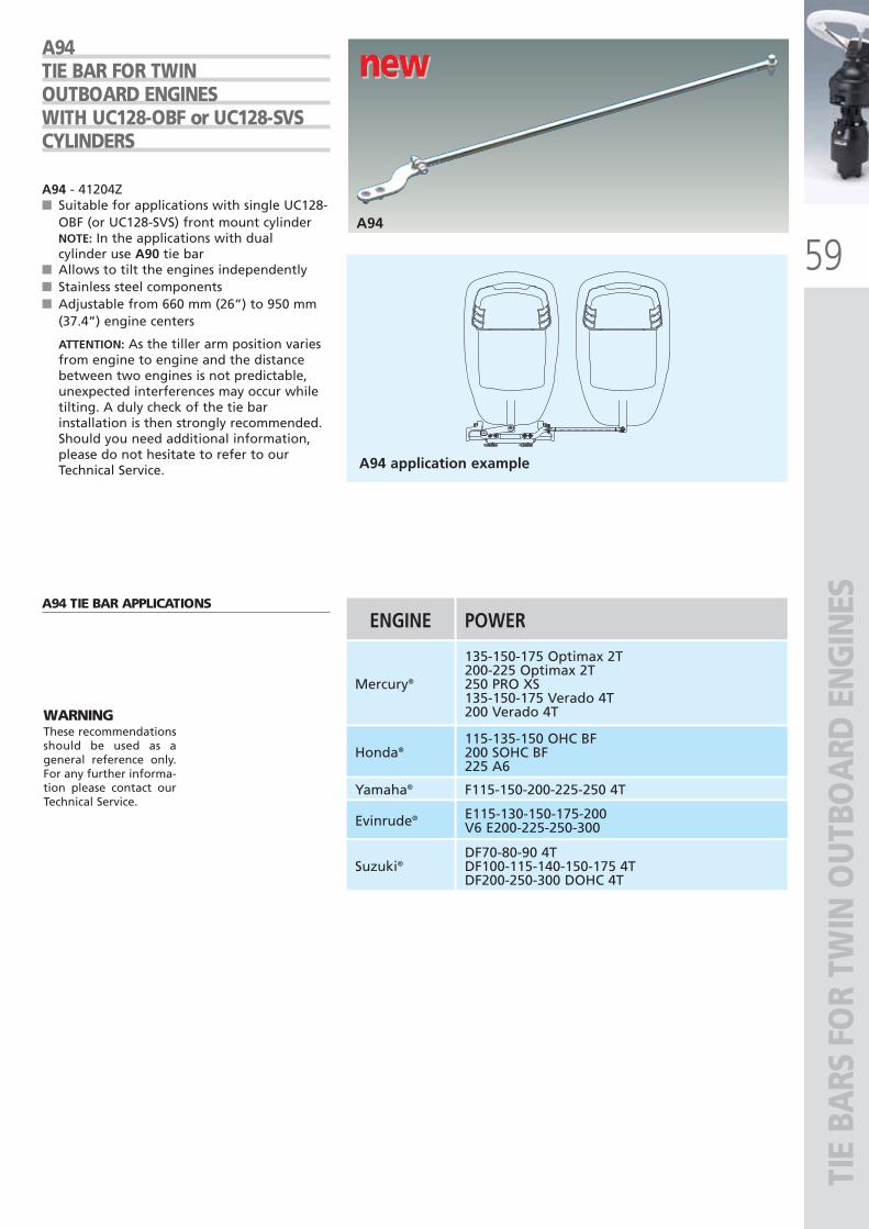
59
new new new
A94
A94 application example
A94 - 41204Z■ Suitable for applications with single UC128-
OBF (or UC128-SVS) front mount cylinderNOTE: In the applications with dualcylinder use A90 tie bar
■ Allows to tilt the engines independently■ Stainless steel components■ Adjustable from 660 mm (26”) to 950 mm
(37.4”) engine centers
ATTENTION: As the tiller arm position variesfrom engine to engine and the distancebetween two engines is not predictable,unexpected interferences may occur whiletilting. A duly check of the tie barinstallation is then strongly recommended.Should you need additional information,please do not hesitate to refer to ourTechnical Service.
A94TIE BAR FOR TWINOUTBOARD ENGINESWITH UC128-OBF or UC128-SVSCYLINDERS
A94 TIE BAR APPLICATIONS
Mercury®
135-150-175 Optimax 2T200-225 Optimax 2T250 PRO XS135-150-175 Verado 4T200 Verado 4T
115-135-150 OHC BF200 SOHC BF225 A6
F115-150-200-225-250 4T
E115-130-150-175-200V6 E200-225-250-300
DF70-80-90 4TDF100-115-140-150-175 4TDF200-250-300 DOHC 4T
Honda®
Yamaha®
Evinrude®
Suzuki®
ENGINE POWER
TIE
BARS
FO
R TW
IN O
UTB
OA
RD E
NG
INES
WARNINGThese recommendationsshould be used as ageneral reference only.For any further informa-tion please contact ourTechnical Service.
ULTRAFLEX2010-Ita:ULTRAFLEX2009-Ita.qxd 18/09/09 17:05 Pagina 59
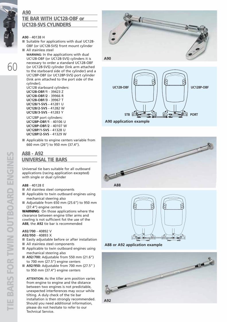
60
TIE
BARS
FO
R TW
IN O
UTB
OA
RD E
NG
INES
A88
Universal tie bars suitable for all outboardapplications (racing application excepted)with single or dual cylinder
A88 - 40128 E■ All stainless steel components■ Applicable to twin outboard engines using
mechanical steering also■ Adjustable from 650 mm (25.6”) to 950 mm
(37.4”) engine centersWARNING: On those applications where theclearance between engine tiller arms andcowling is not sufficient fot the use of theA88, the A92 tie bar is recommended
A92/700 - 40892 V A92/950 - 40893 X■ Easily adjustable before or after installation■ All stainless steel components■ Applicable to twin outboard engines using
mechanical steering also■ A92/700: Adjustable from 550 mm (21.6”)
to 700 mm (27.5”) engine centers■ A92/950: Adjustable from 700 mm (27.5” )
to 950 mm (37.4”) engine centers
ATTENTION: As the tiller arm position variesfrom engine to engine and the distancebetween two engines is not predictable,unexpected interferences may occur whiletilting. A duly check of the tie barinstallation is then strongly recommended.Should you need additional information,please do not hesitate to refer to ourTechnical Service.
A88 - A92UNIVERSAL TIE BARS
A88 or A92 application example
STB PORT
A90
UC128-OBF UC128P-OBF
A90 application example
A92
A90TIE BAR WITH UC128-OBF orUC128-SVS CYLINDERS
A90 - 40138 H■ Suitable for applications with dual UC128-
OBF (or UC128-SVS) front mount cylinder■ All stainless steel
WARNING: In the applications with dualUC128-OBF (or UC128-SVS) cylinders it isnecessary to order a standard UC128-OBF(or UC128-SVS) cylinder (link arm attachedto the starboard side of the cylinder) and aUC128P-OBF (or UC128P-SVS) port cylinder(link arm attached to the port side of thecylinder).UC128 starboard cylinders:UC128-OBF/1 - 39423 ZUC128-OBF/2 - 39966 RUC128-OBF/3 - 39967 TUC128/1-SVS - 41281 UUC128/2-SVS - 41282 WUC128/3-SVS - 41283 Y
UC128P port cylinders:UC128P-OBF/1 - 40106 UUC128P-OBF/2 - 40107 WUC128P/1-SVS - 41328 UUC128P/2-SVS - 41329 W
■ Applicable to engine centers variable from660 mm (26”) to 950 mm (37.4”).
ULTRAFLEX2010-Ita:ULTRAFLEX2009-Ita.qxd 21/09/09 16:23 Pagina 60
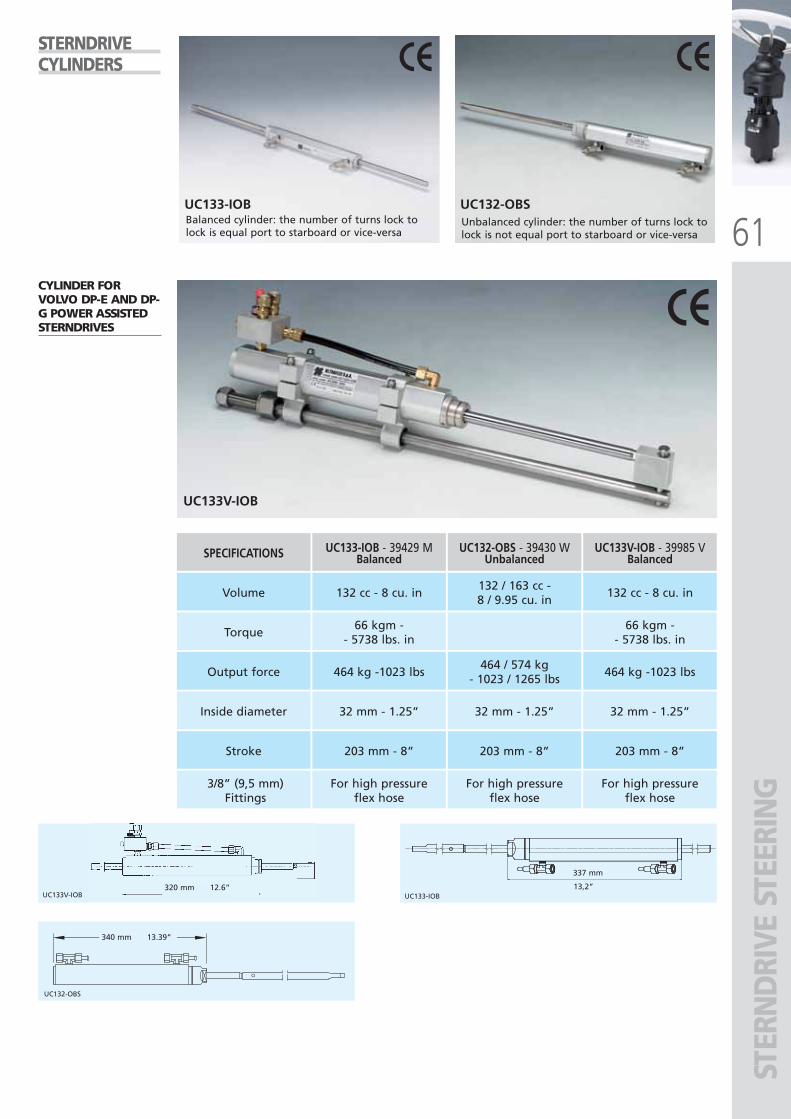
61
UC133V-IOB UC133-IOB
UC132-OBS
337 mm
13,2”320 mm 12.6”
340 mm 13.39”
UC133V-IOB
UC133-IOB UC132-OBS
STER
ND
RIVE
STE
ERIN
G
SPECIFICATIONS UC133-IOB - 39429 MBalanced
UC133V-IOB - 39985 VBalanced
UC132-OBS - 39430 WUnbalanced
Volume 132 cc - 8 cu. in 132 cc - 8 cu. in132 / 163 cc - 8 / 9.95 cu. in
Torque66 kgm -
- 5738 lbs. in66 kgm -
- 5738 lbs. in
Output force 464 kg -1023 lbs 464 kg -1023 lbs464 / 574 kg
- 1023 / 1265 lbs
Inside diameter 32 mm - 1.25” 32 mm - 1.25”32 mm - 1.25”
Stroke 203 mm - 8” 203 mm - 8”203 mm - 8”
3/8” (9,5 mm)Fittings
For high pressureflex hose
For high pressureflex hose
For high pressureflex hose
Balanced cylinder: the number of turns lock tolock is equal port to starboard or vice-versa
Unbalanced cylinder: the number of turns lock tolock is not equal port to starboard or vice-versa
STERNDRIVECYLINDERS
CYLINDER FORVOLVO DP-E AND DP-G POWER ASSISTEDSTERNDRIVES
ULTRAFLEX2010-Ita:ULTRAFLEX2009-Ita.qxd 18/09/09 17:05 Pagina 61
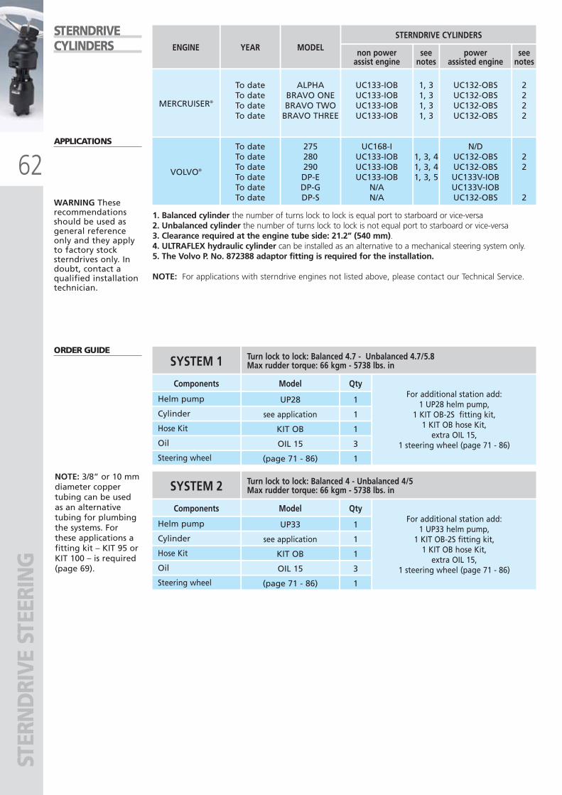
62
STER
ND
RIVE
STE
ERIN
GENGINE
MERCRUISER®
UC133-IOBUC133-IOBUC133-IOBUC133-IOB
VOLVO®
UC168-IUC133-IOBUC133-IOBUC133-IOB
N/AN/A
YEAR
To dateTo dateTo dateTo date
To dateTo dateTo dateTo dateTo dateTo date
UC132-OBSUC132-OBSUC132-OBSUC132-OBS
N/DUC132-OBSUC132-OBSUC133V-IOBUC133V-IOB UC132-OBS
1, 31, 31, 31, 3
1, 3, 41, 3, 41, 3, 5
2222
22
2
MODEL
ALPHABRAVO ONEBRAVO TWO
BRAVO THREE
275280290DP-EDP-GDP-S
STERNDRIVE CYLINDERS
non powerassist engine
powerassisted engine
seenotes
seenotes
1. Balanced cylinder the number of turns lock to lock is equal port to starboard or vice-versa2. Unbalanced cylinder the number of turns lock to lock is not equal port to starboard or vice-versa3. Clearance required at the engine tube side: 21.2” (540 mm).4. ULTRAFLEX hydraulic cylinder can be installed as an alternative to a mechanical steering system only.5. The Volvo P. No. 872388 adaptor fitting is required for the installation.
NOTE: For applications with sterndrive engines not listed above, please contact our Technical Service.
STERNDRIVECYLINDERS
ORDER GUIDE
APPLICATIONS
WARNING Theserecommendationsshould be used asgeneral referenceonly and they applyto factory stocksterndrives only. Indoubt, contact aqualified installationtechnician.
Qty
1
1
1
Components Model
Helm pump UP28
Cylinder see application
For additional station add:1 UP28 helm pump,
1 KIT OB-2S fitting kit,1 KIT OB hose Kit,
extra OIL 15,1 steering wheel (page 71 - 86)
Hose Kit KIT OB
3Oil OIL 15
1Steering wheel (page 71 - 86)
SYSTEM 1 Turn lock to lock: Balanced 4.7 - Unbalanced 4.7/5.8Max rudder torque: 66 kgm - 5738 lbs. in
Qty
1
1
1
Components Model
Helm pump UP33
Cylinder see application
For additional station add:1 UP33 helm pump,
1 KIT OB-2S fitting kit,1 KIT OB hose Kit,
extra OIL 15,1 steering wheel (page 71 - 86)
Hose Kit KIT OB
3Oil OIL 15
1Steering wheel (page 71 - 86)
SYSTEM 2 Turn lock to lock: Balanced 4 - Unbalanced 4/5Max rudder torque: 66 kgm - 5738 lbs. in
NOTE: 3/8” or 10 mmdiameter coppertubing can be usedas an alternativetubing for plumbingthe systems. Forthese applications afitting kit – KIT 95 orKIT 100 – is required(page 69).
ULTRAFLEX2010-Ita:ULTRAFLEX2009-Ita.qxd 21/09/09 16:23 Pagina 62
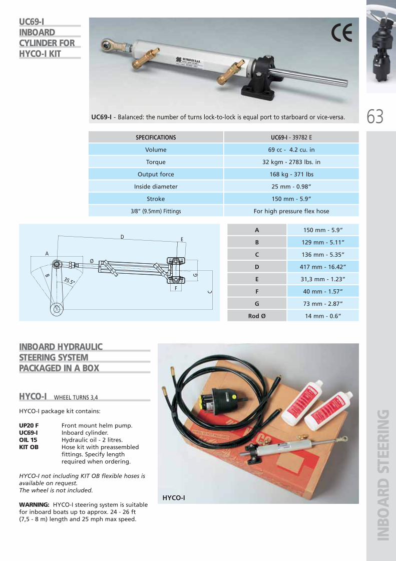
63
HYCO-I
INBO
ARD
STE
ERIN
G
SPECIFICATIONS UC69-I - 39782 E
Volume 69 cc - 4.2 cu. in
Output force 168 kg - 371 lbs
Torque 32 kgm - 2783 lbs. in
Inside diameter 25 mm - 0.98”
Stroke 150 mm - 5.9”
3/8” (9.5mm) Fittings For high pressure flex hose
INBOARD HYDRAULICSTEERING SYSTEMPACKAGED IN A BOX
HYCO-I WHEEL TURNS 3,4
HYCO-I package kit contains:
UP20 F Front mount helm pump.UC69-I Inboard cylinder.OIL 15 Hydraulic oil - 2 litres.KIT OB Hose kit with preassembled
fittings. Specify lengthrequired when ordering.
HYCO-I not including KIT OB flexible hoses isavailable on request.The wheel is not included.
WARNING: HYCO-I steering system is suitablefor inboard boats up to approx. 24 - 26 ft (7,5 - 8 m) length and 25 mph max speed.
UC69-I - Balanced: the number of turns lock-to-lock is equal port to starboard or vice-versa.
UC69-I INBOARD CYLINDER FORHYCO-I KIT
150 mm - 5.9”
129 mm - 5.11”
136 mm - 5.35”
417 mm - 16.42”
31,3 mm - 1.23”
A
B
C
D
E
F 40 mm - 1.57”
G 73 mm - 2.87”
Rod Ø 14 mm - 0.6”
A
35.5°
B
F
D E
G
C
Ø
ULTRAFLEX2010-Ita:ULTRAFLEX2009-Ita.qxd 21/09/09 16:23 Pagina 63
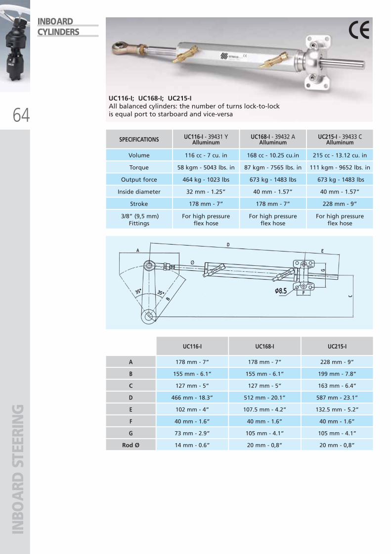
64
INBO
ARD
STE
ERIN
G
UC116-I; UC168-I; UC215-IAll balanced cylinders: the number of turns lock-to-lock is equal port to starboard and vice-versa
INBOARDCYLINDERS
SPECIFICATIONS UC168-I - 39432 AAlluminum
Volume 168 cc - 10.25 cu.in
Torque 87 kgm - 7565 lbs. in
Output force 673 kg - 1483 lbs
Inside diameter 40 mm - 1.57”
Stroke 178 mm - 7”
UC215-I - 39433 CAlluminum
215 cc - 13.12 cu. in
111 kgm - 9652 lbs. in
673 kg - 1483 lbs
40 mm - 1.57”
228 mm - 9”
3/8” (9,5 mm)Fittings
UC116-I - 39431 YAlluminum
116 cc - 7 cu. in
58 kgm - 5043 lbs. in
464 kg - 1023 lbs
32 mm - 1.25”
178 mm - 7”
For high pressureflex hose
For high pressureflex hose
For high pressureflex hose
UC116-I
178 mm - 7”
155 mm - 6.1”
127 mm - 5”
466 mm - 18.3”
102 mm - 4”
UC168-I
178 mm - 7”
155 mm - 6.1”
127 mm - 5”
512 mm - 20.1”
107.5 mm - 4.2”
A
B
C
D
E
F 40 mm - 1.6” 40 mm - 1.6”
UC215-I
228 mm - 9”
199 mm - 7.8”
163 mm - 6.4”
587 mm - 23.1”
132.5 mm - 5.2”
40 mm - 1.6”
G 73 mm - 2.9” 105 mm - 4.1” 105 mm - 4.1”
Rod Ø 14 mm - 0.6” 20 mm - 0,8” 20 mm - 0,8”
Ø
ULTRAFLEX2010-Ita:ULTRAFLEX2009-Ita.qxd 18/09/09 17:06 Pagina 64
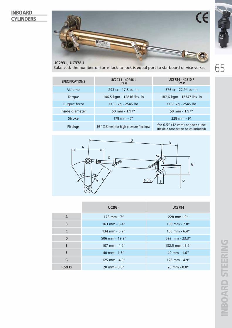
65
INBO
ARD
STE
ERIN
G
ø 8.535° 35°
A
D E
F
G
CB
SPECIFICATIONS UC378-I - 40810 PBrass
Volume 376 cc - 22.94 cu. in
Torque 187,6 kgm - 16347 lbs. in
Output force 1155 kg - 2545 lbs
Inside diameter 50 mm - 1.97”
Stroke 228 mm - 9”
Fittings
UC293-I - 40246 LBrass
293 cc - 17.8 cu. in
146,5 kgm - 12816 lbs. in
1155 kg - 2545 lbs
50 mm - 1.97”
178 mm - 7”
3/8” (9,5 mm) for high pressure flex hose for 0.5” (12 mm) copper tube(flexible connection hoses included)
UC293-I; UC378-IBalanced: the number of turns lock-to-lock is equal port to starboard or vice-versa.
INBOARDCYLINDERS
UC293-I
178 mm - 7”
163 mm - 6.4”
134 mm - 5.2”
506 mm - 19.9”
107 mm - 4.2”
UC378-I
228 mm - 9”
199 mm - 7.8”
163 mm - 6.4”
592 mm - 23.3”
132,5 mm - 5.2”
A
B
C
D
E
F 40 mm - 1.6” 40 mm - 1.6”
G 125 mm - 4.9” 125 mm - 4.9”
Rod Ø 20 mm - 0.8” 20 mm - 0.8”
Ø
ULTRAFLEX2010-Ita:ULTRAFLEX2009-Ita.qxd 18/09/09 17:06 Pagina 65
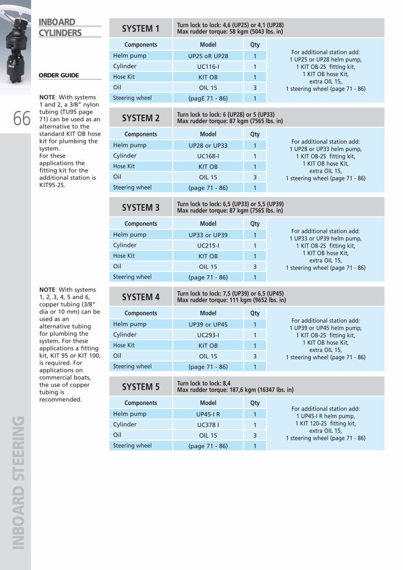
66
INBO
ARD
STE
ERIN
GQty
1
1
1
Components Model
Helm pump UP25 oR UP28
Cylinder UC116-I
For additional station add:1 UP25 or UP28 helm pump,
1 KIT OB-2S fitting kit,1 KIT OB hose Kit,
extra OIL 15,1 steering wheel (page 71 - 86)
Hose Kit KIT OB
3Oil OIL 15
1Steering wheel (pagE 71 - 86)
SYSTEM 1 Turn lock to lock: 4,6 (UP25) or 4,1 (UP28)Max rudder torque: 58 kgm (5043 lbs. in)
Qty
1
1
1
Components Model
Helm pump UP28 or UP33
Cylinder UC168-I
For additional station add:1 UP28 or UP33 helm pump,
1 KIT OB-2S fitting kit,1 KIT OB hose Kit,
extra OIL 15,1 steering wheel (page 71 - 86)
Hose Kit KIT OB
3Oil OIL 15
1Steering wheel (page 71 - 86)
SYSTEM 2 Turn lock to lock: 6 (UP28) or 5 (UP33)Max rudder torque: 87 kgm (7565 lbs. in)
Qty
1
1
1
Components Model
Helm pump UP33 or UP39
Cylinder UC215-I
For additional station add:1 UP33 or UP39 helm pump,
1 KIT OB-2S fitting kit,1 KIT OB hose Kit,
extra OIL 15,1 steering wheel (page 71 - 86)
Hose Kit KIT OB
3Oil OIL 15
1Steering wheel (page 71 - 86)
SYSTEM 3 Turn lock to lock: 6,5 (UP33) or 5,5 (UP39)Max rudder torque: 87 kgm (7565 lbs. in)
Qty
1
1
1
Components Model
Helm pump UP39 or UP45
Cylinder UC293-I
For additional station add:1 UP39 or UP45 helm pump,
1 KIT OB-2S fitting kit,1 KIT OB hose Kit,
extra OIL 15,1 steering wheel (page 71 - 86)
Hose Kit KIT OB
3Oil OIL 15
1Steering wheel (page 71 - 86)
SYSTEM 4 Turn lock to lock: 7,5 (UP39) or 6,5 (UP45)Max rudder torque: 111 kgm (9652 lbs. in)
ORDER GUIDE
NOTE: With systems 1 and 2, a 3/8” nylontubing (TU95 page71) can be used as analternative to thestandard KIT OB hosekit for plumbing thesystem.For theseapplications thefitting kit for theadditional station isKIT95-2S.
NOTE: With systems1, 2, 3, 4, 5 and 6,copper tubing (3/8”dia or 10 mm) can beused as analternative tubingfor plumbing thesystem. For theseapplications a fittingkit, KIT 95 or KIT 100,is required. Forapplications oncommercial boats,the use of coppertubing isrecommended.
INBOARDCYLINDERS
Qty
1
1
Components Model
Helm pump UP45-I R
Cylinder UC378 I
For additional station add:1 UP45-I R helm pump,1 KIT 120-2S fitting kit,
extra OIL 15,1 steering wheel (page 71 - 86)3Oil OIL 15
1Steering wheel (page 71 - 86)
SYSTEM 5 Turn lock to lock: 8,4Max rudder torque: 187,6 kgm (16347 lbs. in)
ULTRAFLEX2010-Ita:ULTRAFLEX2009-Ita.qxd 21/09/09 16:23 Pagina 66
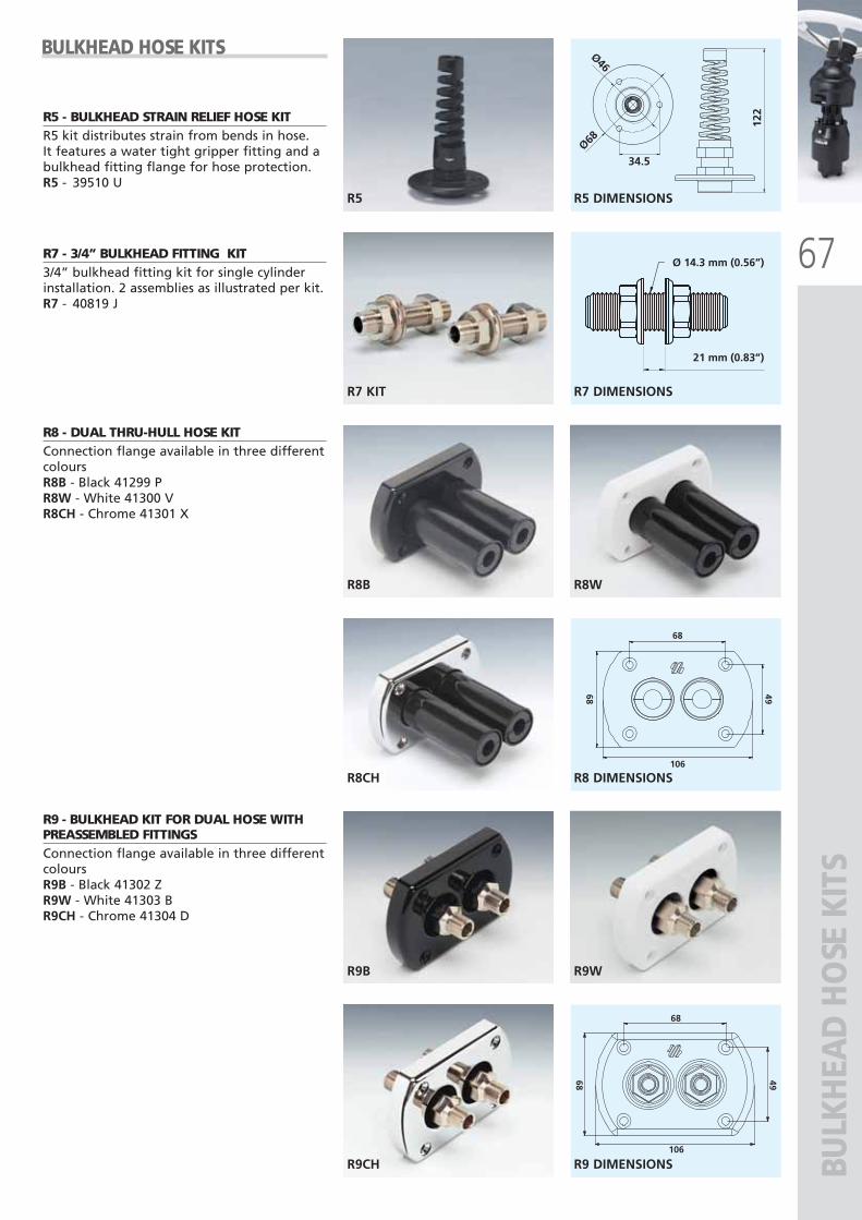
67
R5
122
34.5Ø68
Ø46
R7 KIT
21 mm (0.83”)
Ø 14.3 mm (0.56”)
R8B R8W
R8CH
4968
68
106
R9B R9W
R9CH
68
106
68 49
BULK
HEA
D H
OSE
KIT
S
R5 - BULKHEAD STRAIN RELIEF HOSE KITR5 kit distributes strain from bends in hose. It features a water tight gripper fitting and abulkhead fitting flange for hose protection.R5 - 39510 U
R7 - 3/4” BULKHEAD FITTING KIT3/4” bulkhead fitting kit for single cylinderinstallation. 2 assemblies as illustrated per kit.R7 - 40819 J
R8 - DUAL THRU-HULL HOSE KITConnection flange available in three differentcoloursR8B - Black 41299 PR8W - White 41300 VR8CH - Chrome 41301 X
R9 - BULKHEAD KIT FOR DUAL HOSE WITHPREASSEMBLED FITTINGS Connection flange available in three differentcoloursR9B - Black 41302 ZR9W - White 41303 BR9CH - Chrome 41304 D
R5 DIMENSIONS
R7 DIMENSIONS
R8 DIMENSIONS
R9 DIMENSIONS
BULKHEAD HOSE KITS
ULTRAFLEX2010-Ita:ULTRAFLEX2009-Ita.qxd 18/09/09 17:06 Pagina 67
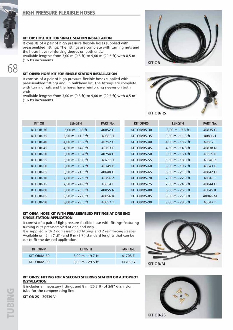
68KIT OB
KIT OB/M
KIT OB/R5
KIT OB-2S
KIT OB/M LENGTH
KIT OB/M-60 6,00 m - 19.7 ft
KIT OB/M-90 9,00 m - 29.5 ft
PART No.
41708 E
41709 G
TUBI
NG
KIT OB: HOSE KIT FOR SINGLE STATION INSTALLATION It consists of a pair of high pressure flexible hoses supplied withpreassembled fittings. The fittings are complete with turning nuts andthe hoses have reinforcing sleeves on both ends.Available lengths: from 3,00 m (9.8 ft) to 9,00 m (29.5 ft) with 0,5 m(1.6 ft) increments.
KIT OB/M: HOSE KIT WITH PREASSEMBLED FITTINGS AT ONE ENDSINGLE STATION APPLICATION It consist of a pair of ligh pressure flexible hose with fittings featuringturning nuts preassembled at one end only.It is supplied with 2 non assembled fittings and 2 reinforcing sleeves.Available on 6 m (1.8’’) and 9 m (2.7’) standard lenghts that can becut to fit the desired application.
KIT OB/R5: HOSE KIT FOR SINGLE STATION INSTALLATIONIt consists of a pair of high pressure flexible hoses supplied withpreassembled fittings and R5 bulkhead kit. The fittings are completewith turning nuts and the hoses have reinforcing sleeves on bothends.Available lengths: from 3,00 m (9.8 ft) to 9,00 m (29.5 ft) with 0,5 m(1.6 ft) increments.
KIT OB-2S: FITTING FOR A SECOND STEERING STATION OR AUTOPILOTINSTALLATIONIt includes all necessary fittings and 8 m (26.3 ft) of 3/8” dia. nylontube for the compensating line
KIT OB-2S - 39539 V
KIT OB LENGTH
KIT OB-30 3,00 m - 9.8 ft
KIT OB-35 3,50 m - 11.5 ft
KIT OB-40 4,00 m - 13.2 ft
KIT OB-45 4,50 m - 14.8 ft
KIT OB-50 5,00 m - 16.4 ft
KIT OB-55 5,50 m - 18.0 ft
KIT OB-60 6,00 m - 19.7 ft
KIT OB-65 6,50 m - 21.3 ft
KIT OB-70 7,00 m - 22.9 ft
KIT OB-75 7,50 m - 24.6 ft
KIT OB-80 8,00 m - 26.3 ft
KIT OB-85 8,50 m - 27.8 ft
KIT OB-90
PART No.
40852 G
40853 J
40752 C
40753 E
40754 G
40755 J
40749 P
40648 H
40796 Z
40854 L
40855 N
40856 R
40857 T9,00 m - 29.5 ft
KIT OB/R5 LENGTH
KIT OB/R5-30 3,00 m - 9.8 ft
KIT OB/R5-35 3,50 m - 11.5 ft
KIT OB/R5-40 4,00 m - 13.2 ft
KIT OB/R5-45 4,50 m - 14.8 ft
KIT OB/R5-50 5,00 m - 16.4 ft
KIT OB/R5-55 5,50 m - 18.0 ft
KIT OB/R5-60 6,00 m - 19.7 ft
KIT OB/R5-65 6,50 m - 21.3 ft
KIT OB/R5-70 7,00 m - 22.9 ft
KIT OB/R5-75 7,50 m - 24.6 ft
KIT OB/R5-80 8,00 m - 26.3 ft
KIT OB/R5-85 8,50 m - 27.8 ft
KIT OB/R5-90
PART No.
40835 G
40836 J
40837 L
40838 N
40839 R
40840 Z
40841 B
40842 D
40843 F
40844 H
40845 K
40846 M
40847 P9,00 m - 29.5 ft
HIGH PRESSURE FLEXIBLE HOSES
ULTRAFLEX2010-Ita:ULTRAFLEX2009-Ita.qxd 21/09/09 16:24 Pagina 68
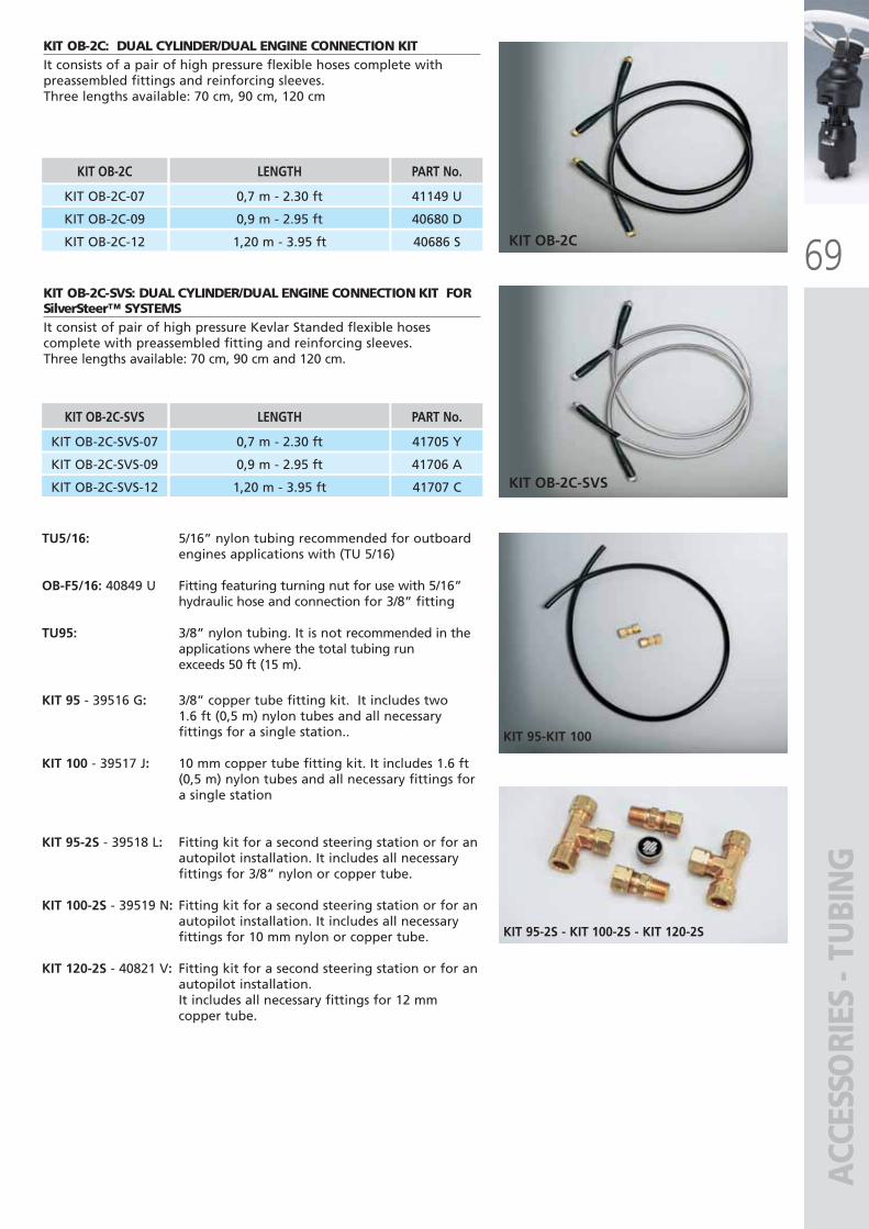
69KIT OB-2C
KIT OB-2C-SVS
KIT 95-KIT 100
KIT 95-2S - KIT 100-2S - KIT 120-2S
ACC
ESSO
RIES
- TU
BIN
G
KIT OB-2C: DUAL CYLINDER/DUAL ENGINE CONNECTION KIT It consists of a pair of high pressure flexible hoses complete withpreassembled fittings and reinforcing sleeves.Three lengths available: 70 cm, 90 cm, 120 cm
KIT OB-2C LENGTH
KIT OB-2C-07 0,7 m - 2.30 ft
KIT OB-2C-09 0,9 m - 2.95 ft
KIT OB-2C-12 1,20 m - 3.95 ft
PART No.
41149 U
40680 D
40686 S
KIT OB-2C-SVS: DUAL CYLINDER/DUAL ENGINE CONNECTION KIT FORSilverSteer™ SYSTEMSIt consist of pair of high pressure Kevlar Standed flexible hosescomplete with preassembled fitting and reinforcing sleeves.Three lengths available: 70 cm, 90 cm and 120 cm.
KIT OB-2C-SVS LENGTH
KIT OB-2C-SVS-07 0,7 m - 2.30 ft
KIT OB-2C-SVS-09 0,9 m - 2.95 ft
PART No.
41705 Y
41706 A
KIT OB-2C-SVS-12 1,20 m - 3.95 ft 41707 C
TU5/16: 5/16” nylon tubing recommended for outboard engines applications with (TU 5/16)
OB-F5/16: 40849 U Fitting featuring turning nut for use with 5/16”hydraulic hose and connection for 3/8” fitting
TU95: 3/8” nylon tubing. It is not recommended in the applications where the total tubing runexceeds 50 ft (15 m).
KIT 95 - 39516 G: 3/8” copper tube fitting kit. It includes two1.6 ft (0,5 m) nylon tubes and all necessary fittings for a single station..
KIT 100 - 39517 J: 10 mm copper tube fitting kit. It includes 1.6 ft (0,5 m) nylon tubes and all necessary fittings for a single station
KIT 95-2S - 39518 L: Fitting kit for a second steering station or for an autopilot installation. It includes all necessary fittings for 3/8” nylon or copper tube.
KIT 100-2S - 39519 N: Fitting kit for a second steering station or for anautopilot installation. It includes all necessary fittings for 10 mm nylon or copper tube.
KIT 120-2S - 40821 V: Fitting kit for a second steering station or for anautopilot installation. It includes all necessary fittings for 12 mm copper tube.
ULTRAFLEX2010-Ita:ULTRAFLEX2009-Ita.qxd 18/09/09 17:06 Pagina 69
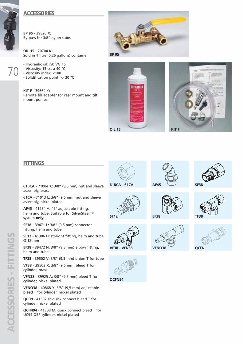
70
61BCA - 61CA
EF38
VFNO38
SF38
TF38
QCFN
SF12
VF38 - VFN38
QCFN94
AF45
BP 95
OIL 15 KIT F
ACC
ESSO
RIES
- FI
TTIN
GS
ACCESSORIES
FITTINGS
61BCA - 71004 K: 3/8” (9,5 mm) nut and sleeveassembly, brass
61CA - 71013 L: 3/8” (9,5 mm) nut and sleeveassembly, nickel plated
AF45 - 41284 A: 45° adjustable fitting, helm and tube. Suitable for SilverSteer™system only.
SF38 - 39471 L: 3/8” (9,5 mm) connectorfitting, helm and tube
SF12 - 41306 H: straight fitting, helm and tubeØ 12 mm
EF38 - 39472 N: 3/8” (9,5 mm) elbow fitting,helm and tube
TF38 - 39502 V: 3/8” (9,5 mm) union T for tube
VF38 - 39503 X: 3/8” (9,5 mm) bleed T forcylinder, brass
VFN38 - 39925 A: 3/8” (9,5 mm) bleed T forcylinder, nickel plated
VFNO38 - 40868 Y: 3/8” (9,5 mm) adjustablebleed T for cylinder, nickel plated
QCFN - 41307 K: quick connect bleed T forcylinder, nickel plated
QCFN94 - 41308 M: quick connect bleed T forUC94-OBF cylinder, nickel plated
BP 95 - 39520 X:By-pass for 3/8” nylon tube.
OIL 15 - 70704 K:Sold in 1 litre (0.26 gallons) container
- Hydraulic oil: IS0 VG 15- Viscosity: 15 cst a 40 °C - Viscosity index: <100- Solidification point: <- 30 °C
KIT F - 39664 Y:Remote fill adapter for rear mount and tiltmount pumps.
ULTRAFLEX2010-Ita:ULTRAFLEX2009-Ita.qxd 18/09/09 17:06 Pagina 70
7711
STEE
RIN
G W
HEE
LSST
EERI
NG
WH
EELS
ULTRAFLEX2010-Ita:ULTRAFLEX2009-Ita.qxd 18/09/09 17:06 Pagina 71
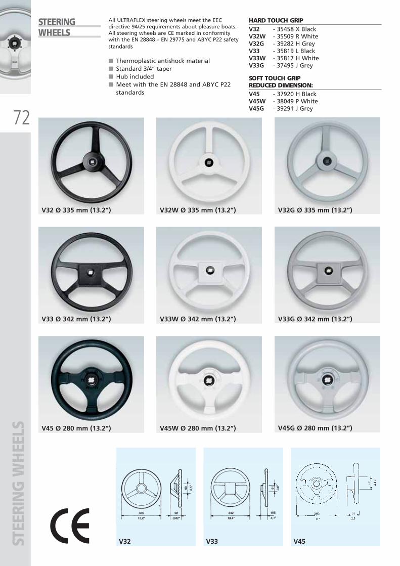
72
V32 V33 V45
V32 Ø 335 mm (13.2”) V32G Ø 335 mm (13.2”) V32W Ø 335 mm (13.2”)
V33 Ø 342 mm (13.2”) V33G Ø 342 mm (13.2”) V33W Ø 342 mm (13.2”)
V45 Ø 280 mm (13.2”) V45G Ø 280 mm (13.2”) V45W Ø 280 mm (13.2”)
STEE
RIN
G W
HEE
LSSTEERINGWHEELS
All ULTRAFLEX steering wheels meet the EECdirective 94/25 requirements about pleasure boats.All steering wheels are CE marked in conformitywith the EN 28848 – EN 29775 and ABYC P22 safetystandards
■ Thermoplastic antishock material■ Standard 3/4’’ taper■ Hub included■ Meet with the EN 28848 and ABYC P22
standards
HARD TOUCH GRIPV32 - 35458 X BlackV32W - 35509 R WhiteV32G - 39282 H GreyV33 - 35819 L BlackV33W - 35817 H WhiteV33G - 37495 J Grey
SOFT TOUCH GRIPREDUCED DIMENSION:V45 - 37920 H BlackV45W - 38049 P WhiteV45G - 39291 J Grey
ULTRAFLEX2010-Ita:ULTRAFLEX2009-Ita.qxd 18/09/09 17:06 Pagina 72
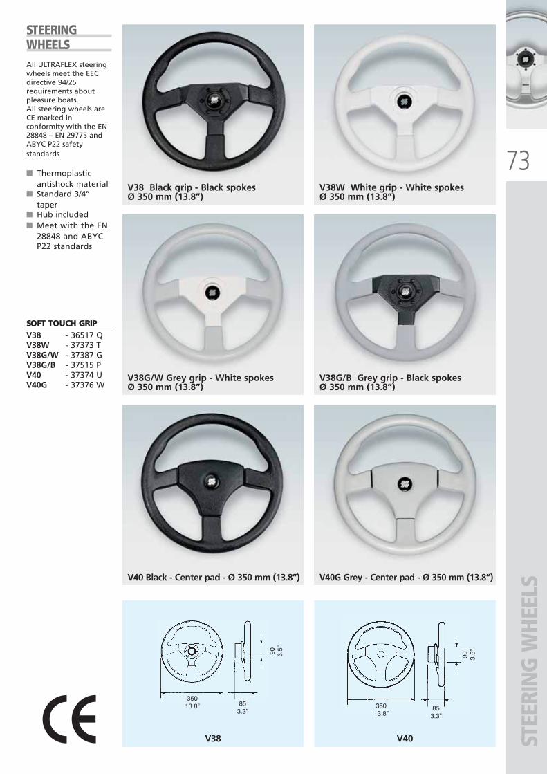
73
35013.8” 85
3.3”
90 3.5”
V38 V40
35013.8”
853.3”
90 3.5”
STEE
RIN
G W
HEE
LS
STEERINGWHEELSAll ULTRAFLEX steeringwheels meet the EECdirective 94/25requirements aboutpleasure boats.All steering wheels areCE marked inconformity with the EN28848 – EN 29775 andABYC P22 safetystandards
■ Thermoplasticantishock material
■ Standard 3/4’’taper
■ Hub included■ Meet with the EN
28848 and ABYCP22 standards
SOFT TOUCH GRIPV38 - 36517 QV38W - 37373 TV38G/W - 37387 GV38G/B - 37515 PV40 - 37374 UV40G - 37376 W
V38 Black grip - Black spokesØ 350 mm (13.8”)
V38W White grip - White spokesØ 350 mm (13.8”)
V38G/W Grey grip - White spokesØ 350 mm (13.8”)
V38G/B Grey grip - Black spokesØ 350 mm (13.8”)
V40 Black - Center pad - Ø 350 mm (13.8”) V40G Grey - Center pad - Ø 350 mm (13.8”)
ULTRAFLEX2010-Ita:ULTRAFLEX2009-Ita.qxd 18/09/09 17:06 Pagina 73
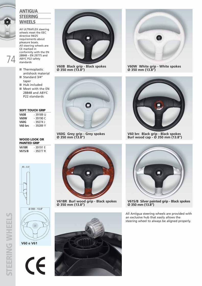
74
V60 e V61
STEE
RIN
G W
HEE
LS
V60B Black grip - Black spokesØ 350 mm (13.8”)
V61S/B Silver painted grip - Black spokesØ 350 mm (13.8”)
ANTIGUASTEERINGWHEELSAll ULTRAFLEX steeringwheels meet the EECdirective 94/25requirements aboutpleasure boats.All steering wheels areCE marked inconformity with the EN28848 – EN 29775 andABYC P22 safetystandards
■ Thermoplasticantishock material
■ Standard 3/4’’taper
■ Hub included■ Meet with the EN
28848 and ABYCP22 standards
SOFT TOUCH GRIPV60B - 39189 UV60W - 39190 CV60G - 39274 JV60 brc - 39289 Y
WOOD LOOK ORPAINTED GRIPV61BR - 39191 EV61S/B - 39277 R
V60W White grip - White spokesØ 350 mm (13.8”)
V60G Grey grip - Grey spokesØ 350 mm (13.8”)
V61BR Burl wood grip - Black spokesØ 350 mm (13.8”)
V60 brc Black grip - Black spokesBurl wood cap - Ø 350 mm (13.8”)
All Antigua steering wheels are provided withan exclusive hub that easily allows thesteering wheel to always be aligned properly.
ULTRAFLEX2010-Ita:ULTRAFLEX2009-Ita.qxd 18/09/09 17:06 Pagina 74
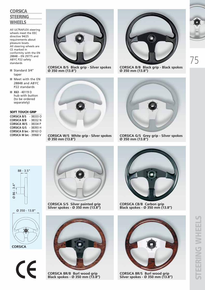
75
CORSICA BR/S Burl wood gripSilver spokes - Ø 350 mm (13.8”)
CORSICA BR/B Burl wood gripBlack spokes - Ø 350 mm (13.8”)
CORSICA B/S Black grip - Silver spokesØ 350 mm (13.8”)
CORSICA CB/B Carbon grip Black spokes - Ø 350 mm (13.8”)
CORSICA B/B Black grip - Black spokesØ 350 mm (13.8”)
CORSICA W/S White grip - Silver spokesØ 350 mm (13.8”)
CORSICA S/S Silver painted gripSilver spokes - Ø 350 mm (13.8”)
CORSICA G/S Grey grip - Silver spokesØ 350 mm (13.8”)
CORSICA
Ø 350 - 13.8”
88 - 3.5”
Ø 8
6 -
3.4”
STEE
RIN
G W
HEE
LS
CORSICASTEERINGWHEELSAll ULTRAFLEX steeringwheels meet the EECdirective 94/25requirements aboutpleasure boats.All steering wheels areCE marked inconformity with the EN28848 – EN 29775 andABYC P22 safetystandards
■ Standard 3/4’’taper
■ Meet with the EN28848 and ABYCP22 standards
■ X63 - 40119 Dhub with button(to be orderedseparately)
SOFT TOUCH GRIPCORSICA B/S - 38333 OCORSICA B/B - 38332 NCORSICA W/S - 38334 PCORSICA G/S - 38393 HCORSICA B brc - 38163 OCORSICA W brc - 39968 V
ULTRAFLEX2010-Ita:ULTRAFLEX2009-Ita.qxd 21/09/09 16:24 Pagina 75
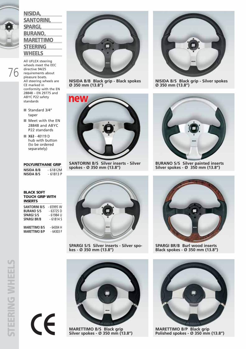
76
new new new
MARETTIMO B/S Black gripSilver spokes - Ø 350 mm (13.8”)
NISIDA B/B Black grip - Black spokesØ 350 mm (13.8”)
SPARGI BR/B Burl wood insertsBlack spokes - Ø 350 mm (13.8”)
NISIDA B/S Black grip - Silver spokesØ 350 mm (13.8”)
SANTORINI B/S Silver inserts - Silverspokes - Ø 350 mm (13.8”)
SPARGI S/S Silver inserts - Silver spo-kes - Ø 350 mm (13.8”)
BURANO S/S Silver painted insertsSilver spokes - Ø 350 mm (13.8”)
MARETTIMO B/P Black gripPolished spokes - Ø 350 mm (13.8”)
NISIDA,SANTORINI,SPARGI,BURANO,MARETTIMOSTEERINGWHEELSAll UFLEX steeringwheels meet the EECdirective 94/25requirements aboutpleasure boats.All steering wheels areCE marked inconformity with the EN28848 – EN 29775 andABYC P22 safetystandards
■ Standard 3/4’’taper
■ Meet with the EN28848 and ABYCP22 standards
■ X63 - 40119 Dhub with button(to be orderedseparately)
POLYURETHANE GRIP NISIDA B/B - 61812MNISIDA B/S - 61813 P
BLACK SOFT TOUCH GRIP WITHINSERTS
SANTORINI B/S - 65995 W BURANO S/S - 63725 DSPARGI S/S - 61984 USPARGI BR/B - 61814 S
MARETTIMO B/S - 64304 HMARETTIMO B/P - 64303 F
STEE
RIN
G W
HEE
LS
ULTRAFLEX2010-Ita:ULTRAFLEX2009-Ita.qxd 21/09/09 16:24 Pagina 76
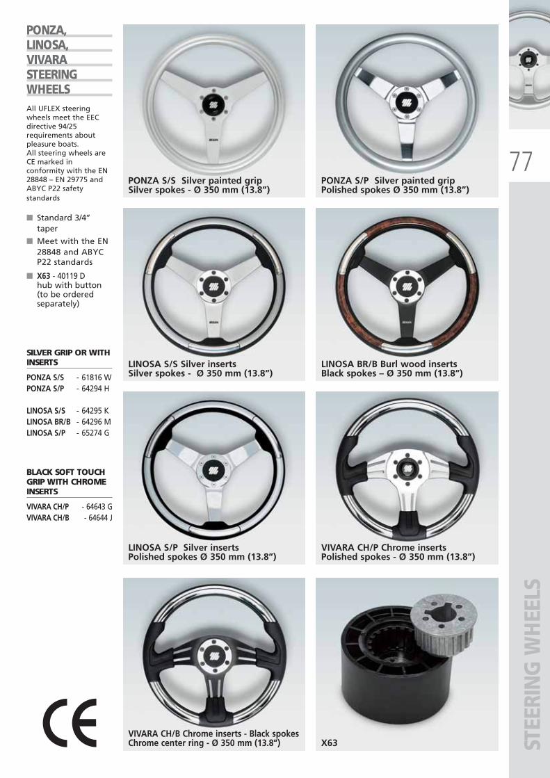
77
STEE
RIN
G W
HEE
LS
PONZA S/S Silver painted gripSilver spokes - Ø 350 mm (13.8”)
VIVARA CH/P Chrome insertsPolished spokes - Ø 350 mm (13.8”)
PONZA,LINOSA,VIVARASTEERINGWHEELSAll UFLEX steeringwheels meet the EECdirective 94/25requirements aboutpleasure boats.All steering wheels areCE marked inconformity with the EN28848 – EN 29775 andABYC P22 safetystandards
■ Standard 3/4’’taper
■ Meet with the EN28848 and ABYCP22 standards
■ X63 - 40119 Dhub with button(to be orderedseparately)
SILVER GRIP OR WITHINSERTS
PONZA S/S - 61816 WPONZA S/P - 64294 H
LINOSA S/S - 64295 KLINOSA BR/B - 64296 MLINOSA S/P - 65274 G
BLACK SOFT TOUCHGRIP WITH CHROMEINSERTS
VIVARA CH/P - 64643 GVIVARA CH/B - 64644 J
PONZA S/P Silver painted gripPolished spokes Ø 350 mm (13.8”)
LINOSA S/S Silver insertsSilver spokes - Ø 350 mm (13.8”)
LINOSA S/P Silver insertsPolished spokes Ø 350 mm (13.8”)
LINOSA BR/B Burl wood insertsBlack spokes – Ø 350 mm (13.8”)
X63VIVARA CH/B Chrome inserts - Black spokesChrome center ring - Ø 350 mm (13.8”)
ULTRAFLEX2010-Ita:ULTRAFLEX2009-Ita.qxd 18/09/09 17:07 Pagina 77
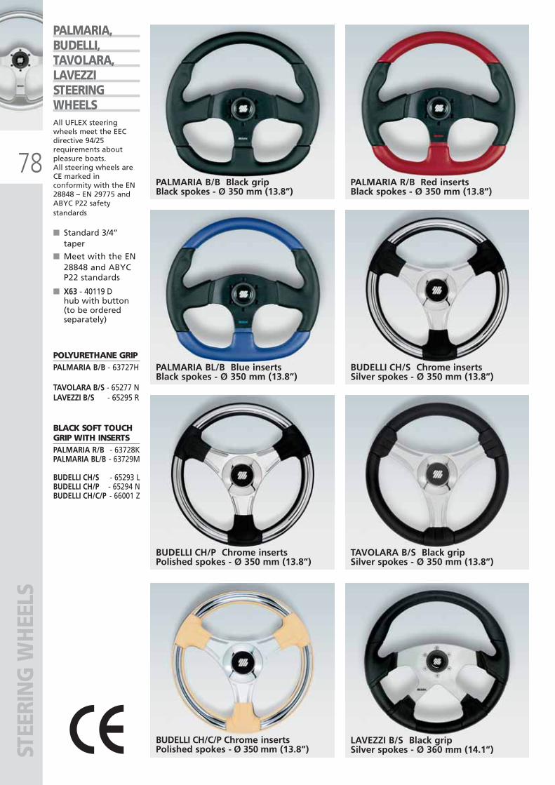
78PALMARIA B/B Black gripBlack spokes - Ø 350 mm (13.8”)
TAVOLARA B/S Black gripSilver spokes - Ø 350 mm (13.8”)
PALMARIA,BUDELLI,TAVOLARA,LAVEZZISTEERINGWHEELSAll UFLEX steeringwheels meet the EECdirective 94/25requirements aboutpleasure boats.All steering wheels areCE marked inconformity with the EN28848 – EN 29775 andABYC P22 safetystandards
■ Standard 3/4’’taper
■ Meet with the EN28848 and ABYCP22 standards
■ X63 - 40119 Dhub with button(to be orderedseparately)
POLYURETHANE GRIPPALMARIA B/B - 63727H
TAVOLARA B/S - 65277 NLAVEZZI B/S - 65295 R
BLACK SOFT TOUCHGRIP WITH INSERTSPALMARIA R/B - 63728KPALMARIA BL/B - 63729M
BUDELLI CH/S - 65293 LBUDELLI CH/P - 65294 NBUDELLI CH/C/P - 66001 Z
PALMARIA R/B Red insertsBlack spokes - Ø 350 mm (13.8”)
PALMARIA BL/B Blue insertsBlack spokes - Ø 350 mm (13.8”)
BUDELLI CH/P Chrome insertsPolished spokes - Ø 350 mm (13.8”)
BUDELLI CH/S Chrome insertsSilver spokes - Ø 350 mm (13.8”)
STEE
RIN
G W
HEE
LS
BUDELLI CH/C/P Chrome insertsPolished spokes - Ø 350 mm (13.8”)
LAVEZZI B/S Black gripSilver spokes - Ø 360 mm (14.1”)
ULTRAFLEX2010-Ita:ULTRAFLEX2009-Ita.qxd 21/09/09 16:26 Pagina 78
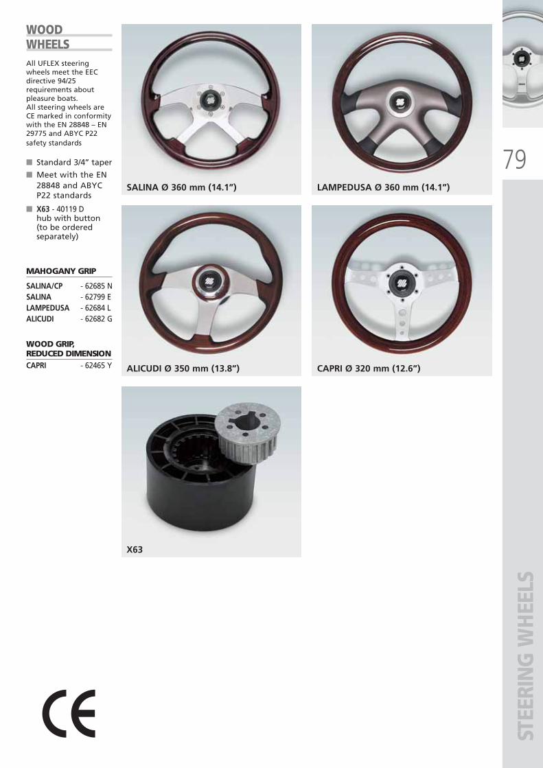
79
STEE
RIN
G W
HEE
LS
SALINA Ø 360 mm (14.1”)
WOODWHEELSAll UFLEX steeringwheels meet the EECdirective 94/25requirements aboutpleasure boats.All steering wheels areCE marked in conformitywith the EN 28848 – EN29775 and ABYC P22safety standards
■ Standard 3/4’’ taper
■ Meet with the EN28848 and ABYCP22 standards
■ X63 - 40119 Dhub with button(to be orderedseparately)
MAHOGANY GRIP
SALINA/CP - 62685 NSALINA - 62799 ELAMPEDUSA - 62684 LALICUDI - 62682 G
WOOD GRIP,REDUCED DIMENSIONCAPRI - 62465 Y
LAMPEDUSA Ø 360 mm (14.1”)
ALICUDI Ø 350 mm (13.8”)
X63
CAPRI Ø 320 mm (12.6”)
ULTRAFLEX2010-Ita:ULTRAFLEX2009-Ita.qxd 18/09/09 17:07 Pagina 79
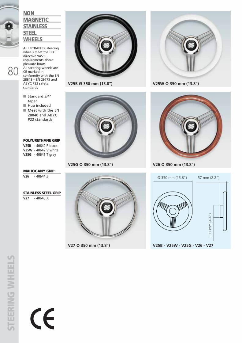
Ø 350 mm (13.8”) 57 mm (2.2”)
111
mm
(4.
4”)
80
V25B - V25W - V25G - V26 - V27
STEE
RIN
G W
HEE
LS
V25B Ø 350 mm (13.8”) V25W Ø 350 mm (13.8”)
V25G Ø 350 mm (13.8”)
V27 Ø 350 mm (13.8”)
V26 Ø 350 mm (13.8”)
NONMAGNETICSTAINLESSSTEELWHEELSAll ULTRAFLEX steeringwheels meet the EECdirective 94/25requirements aboutpleasure boats.All steering wheels areCE marked inconformity with the EN28848 – EN 29775 andABYC P22 safetystandards
■ Standard 3/4’’taper
■ Hub included■ Meet with the EN
28848 and ABYCP22 standards
POLYURETHANE GRIPV25B - 40640 R blackV25W - 40642 V whiteV25G - 40641 T grey
MAHOGANY GRIP V26 - 40644 Z
STAINLESS STEEL GRIPV27 - 40643 X
ULTRAFLEX2010-Ita:ULTRAFLEX2009-Ita.qxd 18/09/09 17:07 Pagina 80
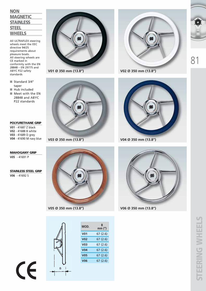
81
STEE
RIN
G W
HEE
LS
V01 Ø 350 mm (13.8”)
V06 Ø 350 mm (13.8”)
V02 Ø 350 mm (13.8”)
V03 Ø 350 mm (13.8”)
V05 Ø 350 mm (13.8”)
V04 Ø 350 mm (13.8”)
MOD. Bmm (“)
V02 67 (2.6)
V01 67 (2.6)
V03 67 (2.6)
V04 67 (2.6)
V05 67 (2.6)
V06 67 (2.6)
NONMAGNETICSTAINLESSSTEELWHEELSAll ULTRAFLEX steeringwheels meet the EECdirective 94/25requirements aboutpleasure boats.All steering wheels areCE marked inconformity with the EN28848 – EN 29775 andABYC P22 safetystandards
■ Standard 3/4’’taper
■ Hub included■ Meet with the EN
28848 and ABYCP22 standards
POLYURETHANE GRIP V01 - 41687 Z blackV02 - 41688 B whiteV03 - 41689 D greyV04 - 41690 M navy blue
MAHOGANY GRIPV05 - 41691 P
STAINLESS STEEL GRIPV06 - 41692 S
ULTRAFLEX2010-Ita:ULTRAFLEX2009-Ita.qxd 18/09/09 17:07 Pagina 81
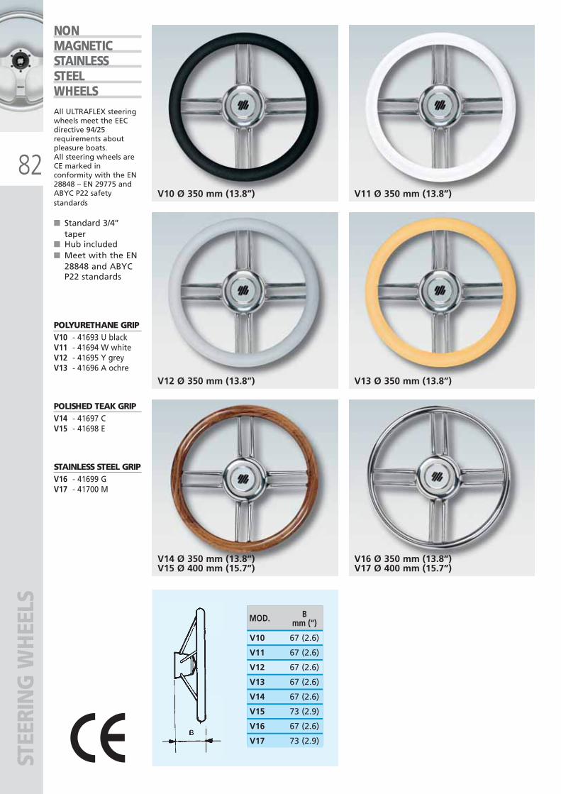
MOD. Bmm (“)
V11 67 (2.6)
V10 67 (2.6)
V12 67 (2.6)
V13 67 (2.6)
V14 67 (2.6)
V15 73 (2.9)
V16 67 (2.6)
V17 73 (2.9)
82V10 Ø 350 mm (13.8”)
V16 Ø 350 mm (13.8”)V17 Ø 400 mm (15.7”)
V11 Ø 350 mm (13.8”)
V12 Ø 350 mm (13.8”)
V14 Ø 350 mm (13.8”)V15 Ø 400 mm (15.7”)
V13 Ø 350 mm (13.8”)
NONMAGNETICSTAINLESSSTEELWHEELSAll ULTRAFLEX steeringwheels meet the EECdirective 94/25requirements aboutpleasure boats.All steering wheels areCE marked inconformity with the EN28848 – EN 29775 andABYC P22 safetystandards
■ Standard 3/4’’taper
■ Hub included■ Meet with the EN
28848 and ABYCP22 standards
POLYURETHANE GRIP V10 - 41693 U blackV11 - 41694 W whiteV12 - 41695 Y greyV13 - 41696 A ochre
POLISHED TEAK GRIP V14 - 41697 CV15 - 41698 E
STAINLESS STEEL GRIPV16 - 41699 GV17 - 41700 M
STEE
RIN
G W
HEE
LS
ULTRAFLEX2010-Ita:ULTRAFLEX2009-Ita.qxd 18/09/09 17:07 Pagina 82
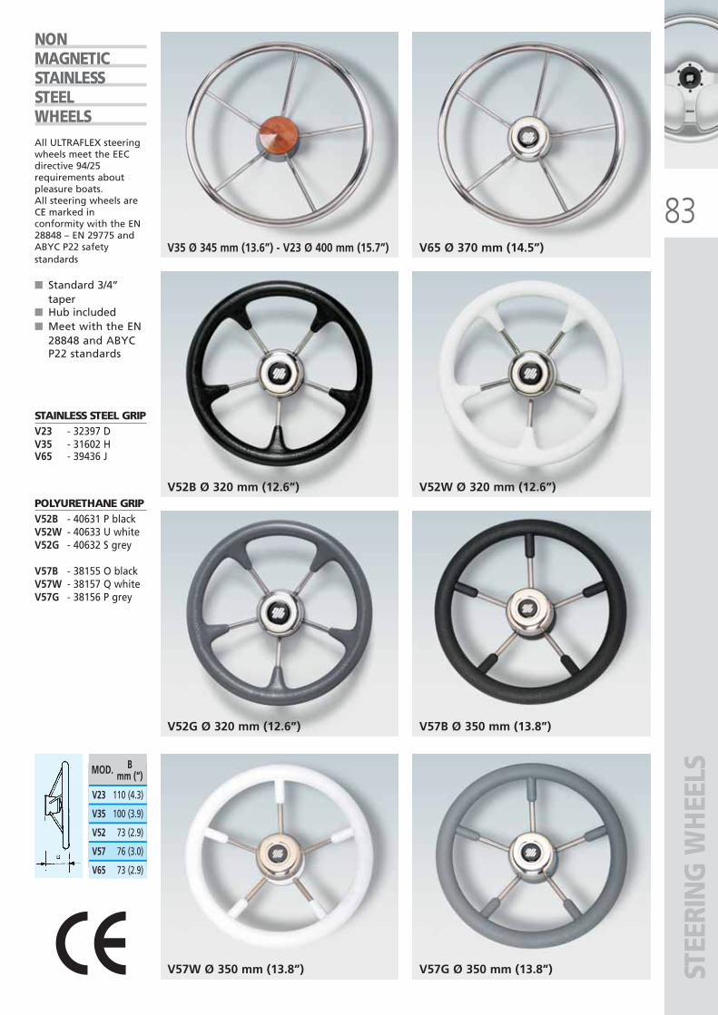
83
STEE
RIN
G W
HEE
LS
V35 Ø 345 mm (13.6”) - V23 Ø 400 mm (15.7”)
V57B Ø 350 mm (13.8”)
V65 Ø 370 mm (14.5”)
V52B Ø 320 mm (12.6”)
V52G Ø 320 mm (12.6”)
V52W Ø 320 mm (12.6”)
V57G Ø 350 mm (13.8”)V57W Ø 350 mm (13.8”)
MOD. Bmm (“)
V35 100 (3.9)
V23 110 (4.3)
V52 73 (2.9)
V57 76 (3.0)
V65 73 (2.9)
NONMAGNETICSTAINLESSSTEELWHEELSAll ULTRAFLEX steeringwheels meet the EECdirective 94/25requirements aboutpleasure boats.All steering wheels areCE marked inconformity with the EN28848 – EN 29775 andABYC P22 safetystandards
■ Standard 3/4’’taper
■ Hub included■ Meet with the EN
28848 and ABYCP22 standards
STAINLESS STEEL GRIPV23 - 32397 DV35 - 31602 HV65 - 39436 J
POLYURETHANE GRIPV52B - 40631 P blackV52W - 40633 U whiteV52G - 40632 S grey
V57B - 38155 O blackV57W - 38157 Q whiteV57G - 38156 P grey
ULTRAFLEX2010-Ita:ULTRAFLEX2009-Ita.qxd 18/09/09 17:07 Pagina 83
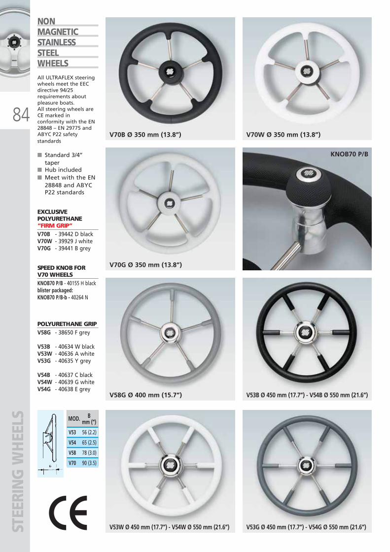
V70B Ø 350 mm (13.8”)
V53B Ø 450 mm (17.7”) - V54B Ø 550 mm (21.6”)
V70W Ø 350 mm (13.8”)
V70G Ø 350 mm (13.8”)
V58G Ø 400 mm (15.7”)
KNOB70 P/B
V53G Ø 450 mm (17.7”) - V54G Ø 550 mm (21.6”)V53W Ø 450 mm (17.7”) - V54W Ø 550 mm (21.6”)
MOD. Bmm (“)
V54 65 (2.5)
V53 56 (2.2)
V58 78 (3.0)
V70 90 (3.5)
84
NONMAGNETICSTAINLESSSTEELWHEELSAll ULTRAFLEX steeringwheels meet the EECdirective 94/25requirements aboutpleasure boats.All steering wheels areCE marked inconformity with the EN28848 – EN 29775 andABYC P22 safetystandards
■ Standard 3/4’’taper
■ Hub included■ Meet with the EN
28848 and ABYCP22 standards
EXCLUSIVEPOLYURETHANE“FIRM GRIP”V70B - 39442 D blackV70W - 39929 J whiteV70G - 39441 B grey
SPEED KNOB FORV70 WHEELSKNOB70 P/B - 40155 H blackblister packaged:KNOB70 P/B-b - 40264 N
POLYURETHANE GRIPV58G - 38650 F grey
V53B - 40634 W blackV53W - 40636 A whiteV53G - 40635 Y grey
V54B - 40637 C blackV54W - 40639 G whiteV54G - 40638 E grey
STEE
RIN
G W
HEE
LS
ULTRAFLEX2010-Ita:ULTRAFLEX2009-Ita.qxd 18/09/09 17:07 Pagina 84
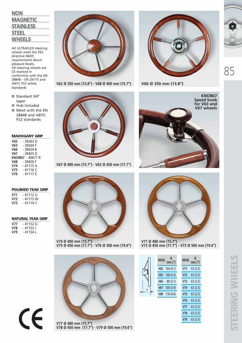
85
STEE
RIN
G W
HEE
LS
V62 Ø 350 mm (13.8”) - V68 Ø 400 mm (15.7”) V66 Ø 350 mm (13.8”)
V67 Ø 400 mm (15.7”) - V63 Ø 450 mm (17.7”)
V74 Ø 400 mm (15.7”)V75 Ø 450 mm (17.7”) - V76 Ø 500 mm (19.6”)
V71 Ø 400 mm (15.7”)V72 Ø 450 mm (17.7”) - V73 Ø 500 mm (19.6”)
V77 Ø 400 mm (15.7”)V78 Ø 450 mm (17.7”) - V79 Ø 500 mm (19.6”)
V63 108 (4.3)
V62 104 (4.1)
V66 80 (3.1)
V67 100 (3.9)
V68 118 (4.6)
MOD. Bmm (“)
V72 63 (2.5)
V71 63 (2.5)
V73 63 (2.5)
V74 63 (2.5)
V75 63 (2.5)
V76 63 (2.5)
V77 63 (2.5)
V78 63 (2.5)
V79 63 (2.5)
MOD. Bmm (“)
NONMAGNETICSTAINLESSSTEELWHEELSAll ULTRAFLEX steeringwheels meet the EECdirective 94/25requirements aboutpleasure boats.All steering wheels areCE marked inconformity with the EN28848 – EN 29775 andABYC P22 safetystandards
■ Standard 3/4’’taper
■ Hub included■ Meet with the EN
28848 and ABYCP22 standards
MAHOGANY GRIPV62 - 39263 DV63 - 39264 FV66 - 39424 BV67 - 39425 DKNOB67 - 40677 RV68 - 39426 FV74 - 41115 AV75 - 41116 CV76 - 41117 E
POLISHED TEAK GRIP V71 - 41112 UV72 - 41113 WV73 - 41114 Y
NATURAL TEAK GRIP V77 - 41152 GV78 - 41153 JV79 - 41154 L
KNOB67Speed knob for V63 and V67 wheels
ULTRAFLEX2010-Ita:ULTRAFLEX2009-Ita.qxd 18/09/09 17:07 Pagina 85
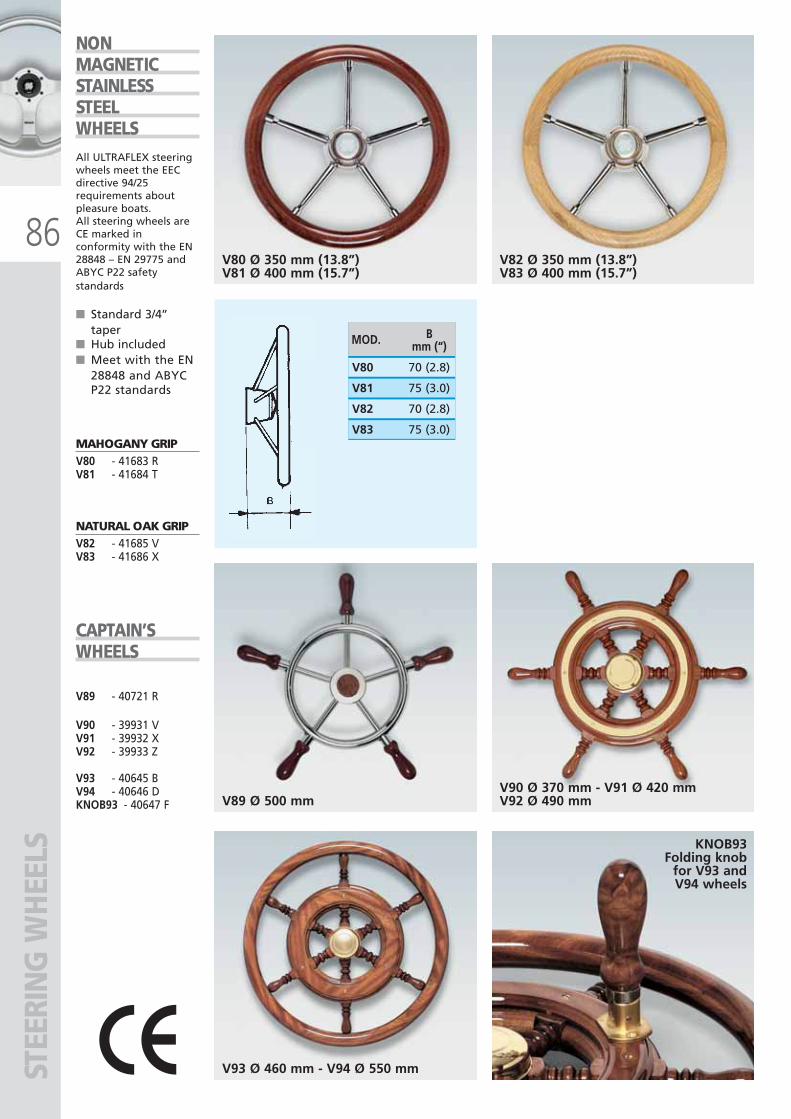
V89 Ø 500 mmV90 Ø 370 mm - V91 Ø 420 mmV92 Ø 490 mm
V93 Ø 460 mm - V94 Ø 550 mm
V80 Ø 350 mm (13.8”)V81 Ø 400 mm (15.7”)
V82 Ø 350 mm (13.8”)V83 Ø 400 mm (15.7”)
MOD. Bmm (“)
V81 75 (3.0)
V80 70 (2.8)
V82 70 (2.8)
V83 75 (3.0)
86
NONMAGNETICSTAINLESSSTEELWHEELSAll ULTRAFLEX steeringwheels meet the EECdirective 94/25requirements aboutpleasure boats.All steering wheels areCE marked inconformity with the EN28848 – EN 29775 andABYC P22 safetystandards
■ Standard 3/4’’taper
■ Hub included■ Meet with the EN
28848 and ABYCP22 standards
MAHOGANY GRIPV80 - 41683 RV81 - 41684 T
NATURAL OAK GRIPV82 - 41685 VV83 - 41686 X
CAPTAIN’SWHEELS
V89 - 40721 R
V90 - 39931 VV91 - 39932 XV92 - 39933 Z
V93 - 40645 BV94 - 40646 DKNOB93 - 40647 F
KNOB93Folding knob
for V93 and V94 wheels
STEE
RIN
G W
HEE
LS
ULTRAFLEX2010-Ita:ULTRAFLEX2009-Ita.qxd 18/09/09 17:07 Pagina 86
MEC
HA
NIC
AL
CON
TRO
L SY
STEM
SM
ECH
AN
ICA
L CO
NTR
OL
SYST
EMS
ULTRAFLEX2010-Ita:ULTRAFLEX2009-Ita.qxd 18/09/09 17:07 Pagina 87
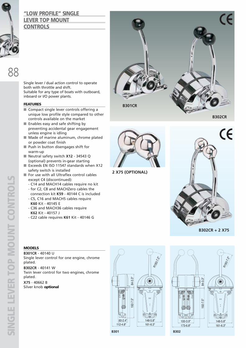
88
2 X75 (OPTIONAL)
B302CR + 2 X75
B301CR
B302CR
B301 B302
112-4.8"60-2.4"
R183
-7.2
"
R183
-7.2
"
161-6.3"148-5.8"
173-6.8"100-3.9"
161-6.3"148-5.8"
192-
7.5"
84-3
.3"
192-
7.5"
84-3
.3"
SIN
GLE
LEV
ER T
OP
MO
UN
T CO
NTR
OLS
Single lever / dual action control to operateboth with throttle and shift.Suitable for any type of boats with outboard,inboard or I/O power plants.
FEATURES■ Compact single lever controls offering a
unique low profile style compared to othercontrols available on the market
■ Enables easy and safe shifting bypreventing accidental gear engagementunless engine is idling
■ Made of marine aluminum, chrome platedor powder coat finish
■ Push in button disengages shift forwarm-up
■ Neutral safety switch X12 - 34543 Q(optional) prevents in-gear starting
■ Exceeds EN ISO 11547 standards when X12safety switch is installed
■ For use with all Ultraflex control cablesexcept C4 (discontinued):- C14 and MACH14 cables require no kit- for C2, C8 and MACHZero cables the
connection kit K59 - 40144 C is included- C5, C16 and MACH5 cables require
K60 Kit - 40145 E- C36 and MACH36 cables require
K62 Kit - 40157 J- C22 cable requires K61 Kit - 40146 G
MODELSB301CR - 40140 USingle lever control for one engine, chromeplated.
B302CR - 40141 WTwin lever control for two engines, chromeplated.
X75 - 40662 BSilver knob optional
“LOW PROFILE” SINGLELEVER TOP MOUNTCONTROLS
ULTRAFLEX2010-Ita:ULTRAFLEX2009-Ita.qxd 18/09/09 17:07 Pagina 88
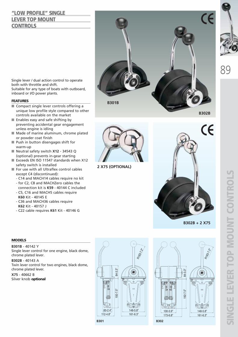
89
B301B
B302B
2 X75 (OPTIONAL)
B302B + 2 X75
B301 B302
112-4.8"60-2.4"
R183
-7.2
"
R183
-7.2
"
161-6.3"148-5.8"
173-6.8"100-3.9"
161-6.3"148-5.8"
192-
7.5"
84-3
.3"
192-
7.5"
84-3
.3"
SIN
GLE
LEV
ER T
OP
MO
UN
T CO
NTR
OLS
Single lever / dual action control to operateboth with throttle and shift.Suitable for any type of boats with outboard,inboard or I/O power plants.
FEATURES■ Compact single lever controls offering a
unique low profile style compared to othercontrols available on the market
■ Enables easy and safe shifting bypreventing accidental gear engagementunless engine is idling
■ Made of marine aluminum, chrome platedor powder coat finish
■ Push in button disengages shift forwarm-up
■ Neutral safety switch X12 - 34543 Q(optional) prevents in-gear starting
■ Exceeds EN ISO 11547 standards when X12safety switch is installed
■ For use with all Ultraflex control cablesexcept C4 (discontinued):- C14 and MACH14 cables require no kit- for C2, C8 and MACHZero cables the
connection kit is K59 - 40144 C included- C5, C16 and MACH5 cables require
K60 Kit - 40145 E- C36 and MACH36 cables require
K62 Kit - 40157 J- C22 cable requires K61 Kit - 40146 G
MODELS
B301B - 40142 YSingle lever control for one engine, black dome,chrome plated lever.
B302B - 40143 ATwin lever control for two engines, black dome,chrome plated lever.
X75 - 40662 BSilver knob optional
“LOW PROFILE” SINGLELEVER TOP MOUNTCONTROLS
ULTRAFLEX2010-Ita:ULTRAFLEX2009-Ita.qxd 18/09/09 17:07 Pagina 89
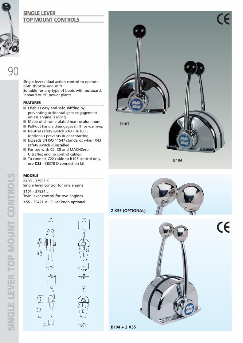
90
B103
B104
B104 + 2 X55
2 X55 (OPTIONAL)
SIN
GLE
LEV
ER T
OP
MO
UN
T CO
NTR
OLS
Single lever / dual action control to operateboth throttle and shift.Suitable for any type of boats with outboard,inboard or I/O power plants.
FEATURES■ Enables easy and safe shifting by
preventing accidental gear engagementunless engine is idling
■ Made of chrome plated marine aluminum■ Pull-out handle disengages shift for warm-up■ Neutral safety switch X43 - 38160 L
(optional) prevents in-gear starting■ Exceeds EN ISO 11547 standards when X43
safety switch is installed■ For use with C2, C8 and MACHZero
Ultraflex engine control cables. ■ To connect C22 cable to B103 control only,
use K33 - 38378 D connection kit
MODELSB103 - 37923 KSingle lever control for one engine
B104 - 37924 LTwin lever control for two engines
X55 - 39421 V - Silver knob optional
SINGLE LEVER TOP MOUNT CONTROLS
ULTRAFLEX2010-Ita:ULTRAFLEX2009-Ita.qxd 18/09/09 17:07 Pagina 90
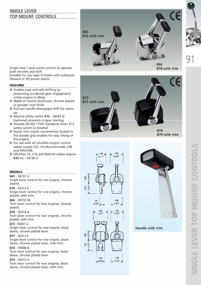
91
B73B77 with trim
B74B79 with trim
B65B76 with trim
B66B78 with trim
SIN
GLE
LEV
ER T
OP
MO
UN
T CO
NTR
OLS
Single lever / dual action control to operateboth throttle and shift.Suitable for any type of boats with outboard,inboard or I/O power plants.
FEATURES■ Enables easy and safe shifting by
preventing accidental gear engagementunless engine is idling
■ Made of marine aluminum, chrome platedor powder coat finish
■ Pull-out handle disengages shift for warm-up
■ Neutral safety switch X12 - 34543 Q(optional) prevents in-gear starting
■ Exceeds EN ISO 11547 standards when X12safety switch is installed
■ Power trim switch conveniently located inthe handle grip enables for easy tilting ofthe engine
■ For use with all Ultraflex engine controlcables except C22, C4 (discontinued), C36and MACH36.
■ Ultraflex C5, C16 and MACH5 cables requireK35 kit - 34730 U
MODELSB65 - 34731 VSingle lever control for one engine, chromeplated.
B76 - 35312 ESingle lever control for one engine, chromeplated, with trim.
B66 - 34732 WTwin lever control for two engines, chromeplated.
B78 - 35314 GTwin lever control for two engines, chromeplated, with trim.
B73 -35007 USingle lever control for one engine, blackdome, chrome plated lever.
B77 - 35313 FSingle lever control for one engine, blackdome, chrome plated lever, with trim.
B74 - 35008 BTwin lever control for two engines, blackdome, chrome plated lever.
B79 - 35315 HTwin lever control for two engines, blackdome, chrome plated lever, with trim.
SINGLE LEVER TOP MOUNT CONTROLS
Handle with trim
ULTRAFLEX2010-Ita:ULTRAFLEX2009-Ita.qxd 18/09/09 17:07 Pagina 91
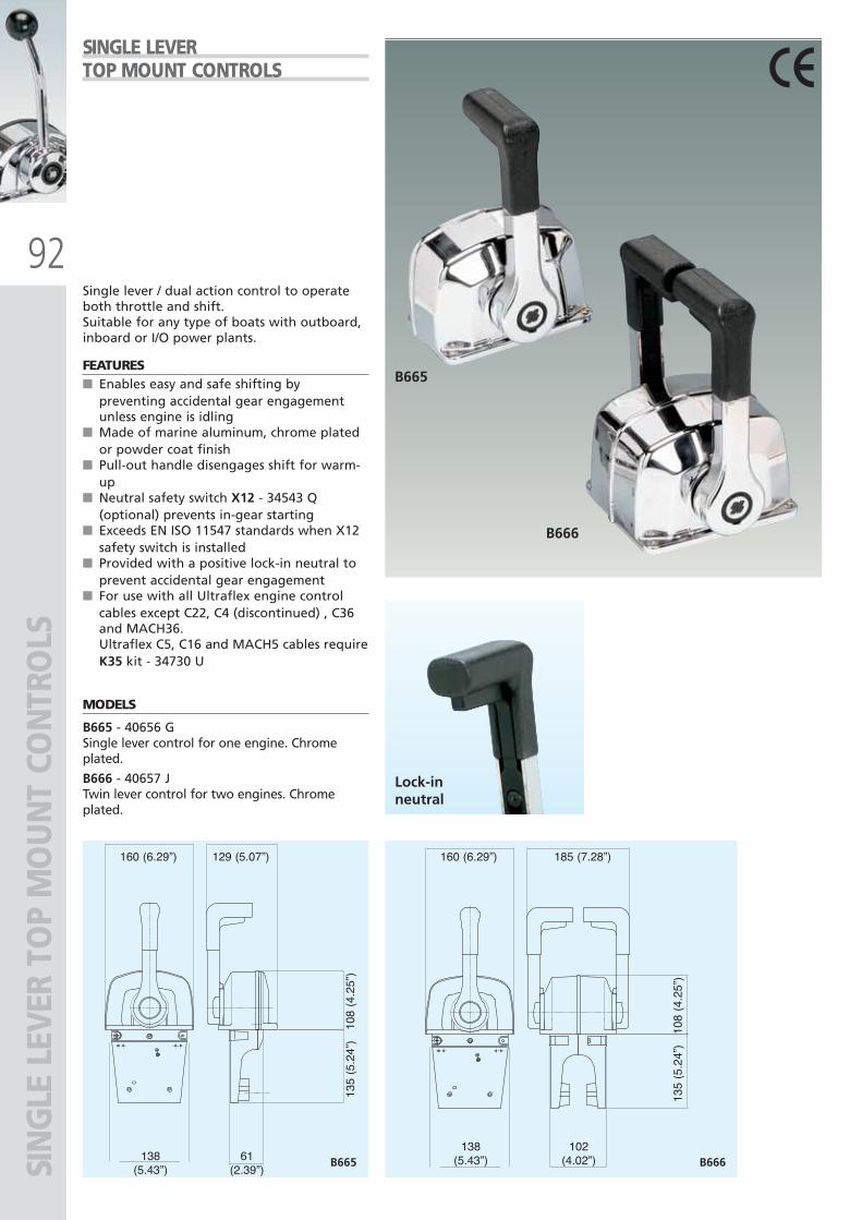
92
B666
B665
Lock-inneutral
B665 B666
108
(4.2
5”)
135
(5.2
4”)
160 (6.29”) 129 (5.07”)
138(5.43”)
61(2.39”)
108
(4.2
5”)
135
(5.2
4”)
160 (6.29”) 185 (7.28”)
138(5.43”)
102(4.02”)SI
NG
LE L
EVER
TO
P M
OU
NT
CON
TRO
LS
Single lever / dual action control to operateboth throttle and shift.Suitable for any type of boats with outboard,inboard or I/O power plants.
FEATURES■ Enables easy and safe shifting by
preventing accidental gear engagementunless engine is idling
■ Made of marine aluminum, chrome platedor powder coat finish
■ Pull-out handle disengages shift for warm-up
■ Neutral safety switch X12 - 34543 Q(optional) prevents in-gear starting
■ Exceeds EN ISO 11547 standards when X12safety switch is installed
■ Provided with a positive lock-in neutral toprevent accidental gear engagement
■ For use with all Ultraflex engine controlcables except C22, C4 (discontinued) , C36and MACH36.Ultraflex C5, C16 and MACH5 cables requireK35 kit - 34730 U
MODELS
B665 - 40656 GSingle lever control for one engine. Chromeplated.
B666 - 40657 JTwin lever control for two engines. Chromeplated.
SINGLE LEVER TOP MOUNT CONTROLS
ULTRAFLEX2010-Ita:ULTRAFLEX2009-Ita.qxd 18/09/09 17:07 Pagina 92
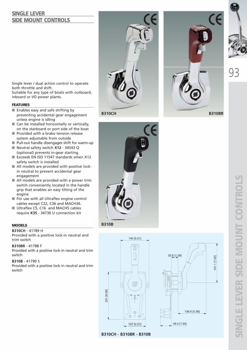
93
B310B
B310CH B310BR
191.
1[7
.52]
136.6 [5.38]
32.6 [1.28]
49.5 [1.95]
140 [5.51]
231
[9.0
9]
107 [4.21]
B310CH - B310BR - B310B SIN
GLE
LEV
ER S
IDE
MO
UN
T CO
NTR
OLS
SINGLE LEVER SIDE MOUNT CONTROLS
Single lever / dual action control to operateboth throttle and shift.Suitable for any type of boats with outboard,inboard or I/O power plants.
FEATURES■ Enables easy and safe shifting by
preventing accidental gear engagementunless engine is idling
■ Can be installed horizontally or vertically,on the starboard or port side of the boat
■ Provided with a brake tension releasesystem adjustable from outside
■ Pull-out handle disengages shift for warm-up■ Neutral safety switch X12 - 34543 Q
(optional) prevents in-gear starting■ Exceeds EN ISO 11547 standards when X12
safety switch is installed■ All models are provided with positive lock-
in neutral to prevent accidental gearengagement
■ All models are provided with a power trimswitch conveniently located in the handlegrip that enables an easy tilting of theengine
■ For use with all Ultraflex engine controlcables except C22, C36 and MACH36.
■ Ultraflex C5, C16 and MACH5 cablesrequire K35 - 34730 U connection kit
MODELSB310CH - 41789 HProvided with a positive lock-in neutral andtrim switch
B310BR - 41788 FProvided with a positive lock-in neutral and trimswitch
B310B - 41790 SProvided with a positive lock-in neutral and trimswitch
ULTRAFLEX2010-Ita:ULTRAFLEX2009-Ita.qxd 18/09/09 17:07 Pagina 93
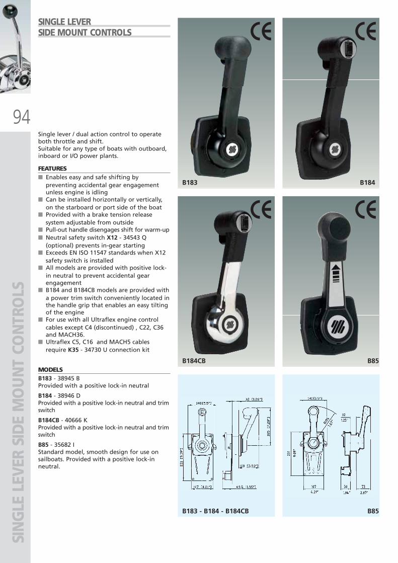
94
B183 - B184 - B184CB B85
B184CB B85
B183 B184
SIN
GLE
LEV
ER S
IDE
MO
UN
T CO
NTR
OLS
SINGLE LEVER SIDE MOUNT CONTROLS
Single lever / dual action control to operateboth throttle and shift.Suitable for any type of boats with outboard,inboard or I/O power plants.
FEATURES■ Enables easy and safe shifting by
preventing accidental gear engagementunless engine is idling
■ Can be installed horizontally or vertically,on the starboard or port side of the boat
■ Provided with a brake tension releasesystem adjustable from outside
■ Pull-out handle disengages shift for warm-up■ Neutral safety switch X12 - 34543 Q
(optional) prevents in-gear starting■ Exceeds EN ISO 11547 standards when X12
safety switch is installed■ All models are provided with positive lock-
in neutral to prevent accidental gearengagement
■ B184 and B184CB models are provided witha power trim switch conveniently located inthe handle grip that enables an easy tiltingof the engine
■ For use with all Ultraflex engine controlcables except C4 (discontinued) , C22, C36and MACH36.
■ Ultraflex C5, C16 and MACH5 cablesrequire K35 - 34730 U connection kit
MODELSB183 - 38945 BProvided with a positive lock-in neutral
B184 - 38946 DProvided with a positive lock-in neutral and trimswitch
B184CB - 40666 KProvided with a positive lock-in neutral and trimswitch
B85 - 35682 IStandard model, smooth design for use onsailboats. Provided with a positive lock-inneutral.
ULTRAFLEX2010-Ita:ULTRAFLEX2009-Ita.qxd 18/09/09 17:07 Pagina 94
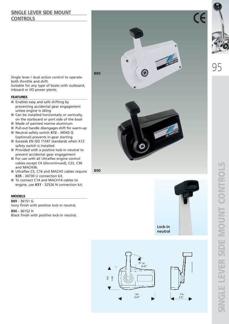
95
B90
B89
Lock-inneutral
SIN
GLE
LEV
ER S
IDE
MO
UN
T CO
NTR
OLS
Single lever / dual action control to operateboth throttle and shift.Suitable for any type of boats with outboard,inboard or I/O power plants.
FEATURES■ Enables easy and safe shifting by
preventing accidental gear engagementunless engine is idling
■ Can be installed horizontally or vertically,on the starboard or port side of the boat
■ Made of painted marine aluminum■ Pull-out handle disengages shift for warm-up■ Neutral safety switch X12 - 34543 Q
(optional) prevents in-gear starting■ Exceeds EN ISO 11547 standards when X12
safety switch is installed■ Provided with a positive lock-in neutral to
prevent accidental gear engagement■ For use with all Ultraflex engine control
cables except C4 (discontinued), C22, C36and MACH36.
■ Ultraflex C5, C16 and MACH5 cables requireK35 - 34730 U connection kit.
■ To connect C14 and MACH14 cables toengine, use K51 - 32526 N connection kit.
MODELSB89 - 36151 GIvory finish with positive lock-in neutral.
B90 - 36152 HBlack finish with positive lock-in neutral.
SINGLE LEVER SIDE MOUNTCONTROLS
ULTRAFLEX2010-Ita:ULTRAFLEX2009-Ita.qxd 18/09/09 17:07 Pagina 95
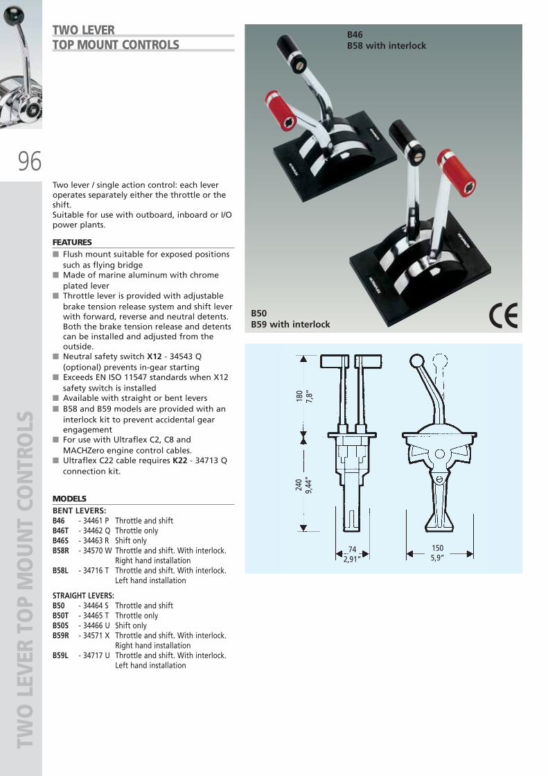
96
180
7,8”
240
9,44
”
742,91”
1505,9”
B46B58 with interlock
B50B59 with interlock
TWO
LEV
ER T
OP
MO
UN
T CO
NTR
OLS
Two lever / single action control: each leveroperates separately either the throttle or theshift.Suitable for use with outboard, inboard or I/Opower plants.
FEATURES■ Flush mount suitable for exposed positions
such as flying bridge■ Made of marine aluminum with chrome
plated lever■ Throttle lever is provided with adjustable
brake tension release system and shift leverwith forward, reverse and neutral detents.Both the brake tension release and detentscan be installed and adjusted from theoutside.
■ Neutral safety switch X12 - 34543 Q(optional) prevents in-gear starting
■ Exceeds EN ISO 11547 standards when X12safety switch is installed
■ Available with straight or bent levers■ B58 and B59 models are provided with an
interlock kit to prevent accidental gearengagement
■ For use with Ultraflex C2, C8 andMACHZero engine control cables.
■ Ultraflex C22 cable requires K22 - 34713 Qconnection kit.
MODELSBENT LEVERS:B46 - 34461 P Throttle and shiftB46T - 34462 Q Throttle onlyB46S - 34463 R Shift onlyB58R - 34570 W Throttle and shift. With interlock.
Right hand installationB58L - 34716 T Throttle and shift. With interlock.
Left hand installation
STRAIGHT LEVERS:B50 - 34464 S Throttle and shiftB50T - 34465 T Throttle onlyB50S - 34466 U Shift onlyB59R - 34571 X Throttle and shift. With interlock.
Right hand installationB59L - 34717 U Throttle and shift. With interlock.
Left hand installation
TWO LEVER TOP MOUNT CONTROLS
ULTRAFLEX2010-Ita:ULTRAFLEX2009-Ita.qxd 18/09/09 17:07 Pagina 96
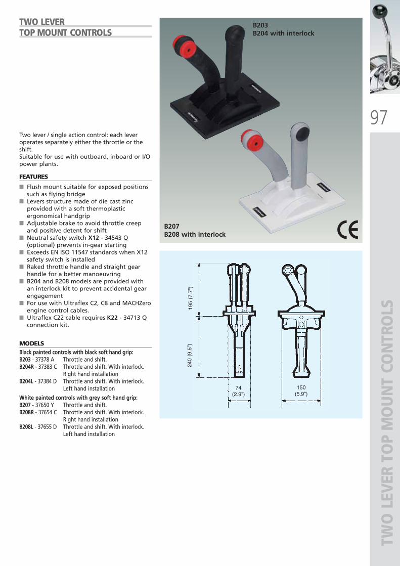
97
195
(7.7
”)24
0 (9
.5”)
74(2.9”)
150(5.9”)
B203B204 with interlock
B207B208 with interlock
TWO
LEV
ER T
OP
MO
UN
T CO
NTR
OLS
Two lever / single action control: each leveroperates separately either the throttle or theshift.Suitable for use with outboard, inboard or I/Opower plants.
FEATURES
■ Flush mount suitable for exposed positionssuch as flying bridge
■ Levers structure made of die cast zincprovided with a soft thermoplasticergonomical handgrip
■ Adjustable brake to avoid throttle creepand positive detent for shift
■ Neutral safety switch X12 - 34543 Q(optional) prevents in-gear starting
■ Exceeds EN ISO 11547 standards when X12safety switch is installed
■ Raked throttle handle and straight gearhandle for a better manoeuvring
■ B204 and B208 models are provided withan interlock kit to prevent accidental gearengagement
■ For use with Ultraflex C2, C8 and MACHZeroengine control cables.
■ Ultraflex C22 cable requires K22 - 34713 Qconnection kit.
MODELSBlack painted controls with black soft hand grip:B203 - 37378 A Throttle and shift.B204R - 37383 C Throttle and shift. With interlock.
Right hand installationB204L - 37384 D Throttle and shift. With interlock.
Left hand installation
White painted controls with grey soft hand grip:B207 - 37650 Y Throttle and shift. B208R - 37654 C Throttle and shift. With interlock.
Right hand installationB208L - 37655 D Throttle and shift. With interlock.
Left hand installation
TWO LEVER TOP MOUNT CONTROLS
ULTRAFLEX2010-Ita:ULTRAFLEX2009-Ita.qxd 18/09/09 17:07 Pagina 97
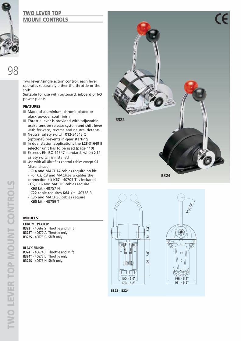
98
B322
B324
B322 - B324
173 - 6.8”100 - 3.9”
161 - 6.3”148 - 5.8”
84 -
3.3
”19
3 -
7.6”
R183
-7.2
"
TWO
LEV
ER T
OP
MO
UN
T CO
NTR
OLS
Two lever / single action control: each leveroperates separately either the throttle or theshift.Suitable for use with outboard, inboard or I/Opower plants.
FEATURES■ Made of aluminium, chrome plated or
black powder coat finish■ Throttle lever is provided with adjustable
brake tension release system and shift leverwith forward, reverse and neutral detents.
■ Neutral safety switch X12-34543 Q(optional) prevents in-gear starting
■ In dual station applications the L23-31649 Bselector unit has to be used (page 110)
■ Exceeds EN ISO 11547 standards when X12safety switch is installed
■ Use with all Ultraflex control cables except C4(discontinued):- C14 and MACH14 cables require no kit - For C2, C8 and MACHZero cables the connection kit K67 - 40705 T is included - C5, C16 and MACH5 cables require
K63 kit - 40757 N- C22 cable requires K64 kit - 40758 R- C36 and MACH36 cables require
K65 kit - 40759 T
MODELS
CHROME PLATED:B322 - 40669 S Throttle and shiftB322T - 40670 A Throttle onlyB322S - 40673 G Shift only
BLACK FINISH:B324 - 40674 J Throttle and shiftB324T - 40675 L Throttle onlyB324S - 40676 N Shift only
TWO LEVER TOPMOUNT CONTROLS
ULTRAFLEX2010-Ita:ULTRAFLEX2009-Ita.qxd 18/09/09 17:07 Pagina 98
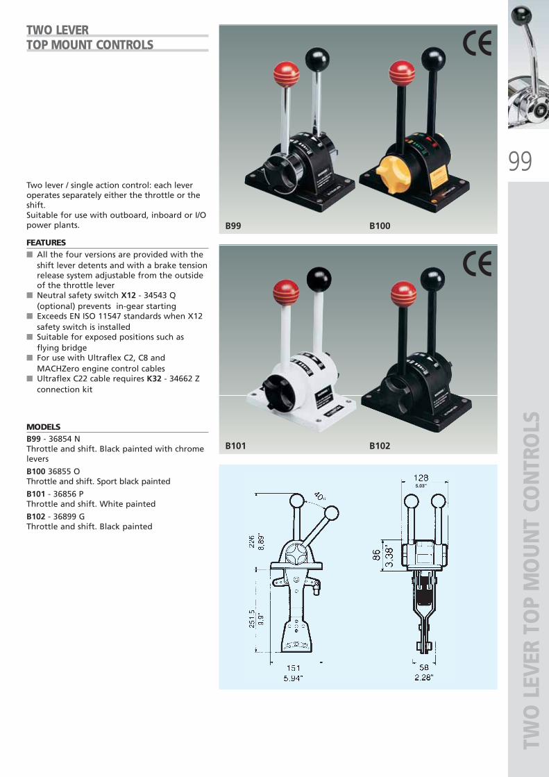
99
B99 B100
B101 B102
5.03”
TWO
LEV
ER T
OP
MO
UN
T CO
NTR
OLS
Two lever / single action control: each leveroperates separately either the throttle or theshift.Suitable for use with outboard, inboard or I/Opower plants.
FEATURES■ All the four versions are provided with the
shift lever detents and with a brake tensionrelease system adjustable from the outsideof the throttle lever
■ Neutral safety switch X12 - 34543 Q(optional) prevents in-gear starting
■ Exceeds EN ISO 11547 standards when X12safety switch is installed
■ Suitable for exposed positions such asflying bridge
■ For use with Ultraflex C2, C8 andMACHZero engine control cables
■ Ultraflex C22 cable requires K32 - 34662 Zconnection kit
MODELSB99 - 36854 N Throttle and shift. Black painted with chromelevers
B100 36855 OThrottle and shift. Sport black painted
B101 - 36856 PThrottle and shift. White painted
B102 - 36899 GThrottle and shift. Black painted
TWO LEVER TOP MOUNT CONTROLS
ULTRAFLEX2010-Ita:ULTRAFLEX2009-Ita.qxd 18/09/09 17:07 Pagina 99
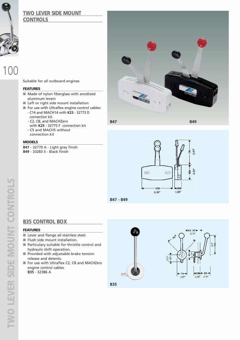
100
B47 B49
B47 - B49
B35
TWO
LEV
ER S
IDE
MO
UN
T CO
NTR
OLS
Suitable for all outboard engines.
FEATURES■ Made of nylon fiberglass with anodized
aluminum levers■ Left or right side mount installation■ For use with Ultraflex engine control cables:
- C14 and MACH14 with K23 - 32773 Dconnection kit
- C2, C8, and MACHZerowith K25 - 32775 F connection kit
- C5 and MACH5 withoutconnection kit
MODELSB47 - 32770 A - Light grey finishB49 - 33283 S - Black finish
B35 CONTROL BOXFEATURES■ Lever and flange all stainless steel.■ Flush side mount installation.■ Particulary suitable for throttle control and
hydraulic shift operation.■ Provided with adjustable brake tension
release and detents.■ For use with Ultraflex C2, C8 and MACHZero
engine control cablesB35 - 32386 A
TWO LEVER SIDE MOUNTCONTROLS
ULTRAFLEX2010-Ita:ULTRAFLEX2009-Ita.qxd 18/09/09 17:07 Pagina 100
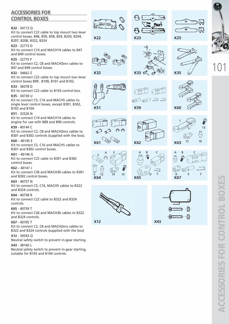
101K32 K33
K22 K23 K25
K35
K51 K59 K60
K61 K62
1
13
1012
2A 3
5 12 14 15
K63
K64
BA C
D FK65
BA C
D E FK67
X12 X43A
CCES
SORI
ES F
OR
CON
TRO
L BO
XES
K22 - 34713 QKit to connect C22 cable to top mount two levercontrol boxes, B46, B50, B58, B59, B203, B204,B207, B208, B322, B324
K23 - 32773 DKit to connect C14 and MACH14 cables to B47and B49 control boxes.
K25 - 32775 FKit to connect C2, C8 and MACHZero cables toB47 and B49 control boxes.
K32 - 34662 ZKit to connect C22 cable to top mount two levercontrol boxes B99 , B100, B101 and B102.
K33 - 38378 DKit to connect C22 cable to B103 control box.
K35 - 34730 UKit to connect C5, C16 and MACH5 cables tosingle lever control boxes, except B301, B302,B103 and B104.
K51 - 32526 NKit to connect C14 and MACH14 cables toengine for use with B89 and B90 controls.
K59 - 40144 CKit to connect C2, C8 and MACHZero cables toB301 and B302 controls (supplied with the box).
K60 – 40145 EKit to connect C5, C16 and MACH5 cables toB301 and B302 control boxes.
K61 – 40146 GKit to connect C22 cable to B301 and B302control boxes.
K62 – 40147 JKit to connect C36 and MACH36 cables to B301and B302 control boxes.
K63 - 40757 NKit to connect C5, C16, MACH5 cables to B322and B324 controls.
K64 - 40758 RKit to connect C22 cable to B322 and B324controls.
K65 - 40759 TKit to connect C36 and MACH36 cables to B322and B324 controls.
K67 - 40705 TKit to connect C2, C8 and MACHZero cables toB322 and B324 controls (supplied with the box)
X12 - 34543 QNeutral safety switch to prevent in-gear starting.
X43 - 38160 LNeutral safety switch to prevent in-gear starting,suitable for B103 and B104 controls.
ACCESSORIES FORCONTROL BOXES
ULTRAFLEX2010-Ita:ULTRAFLEX2009-Ita.qxd 18/09/09 17:07 Pagina 101
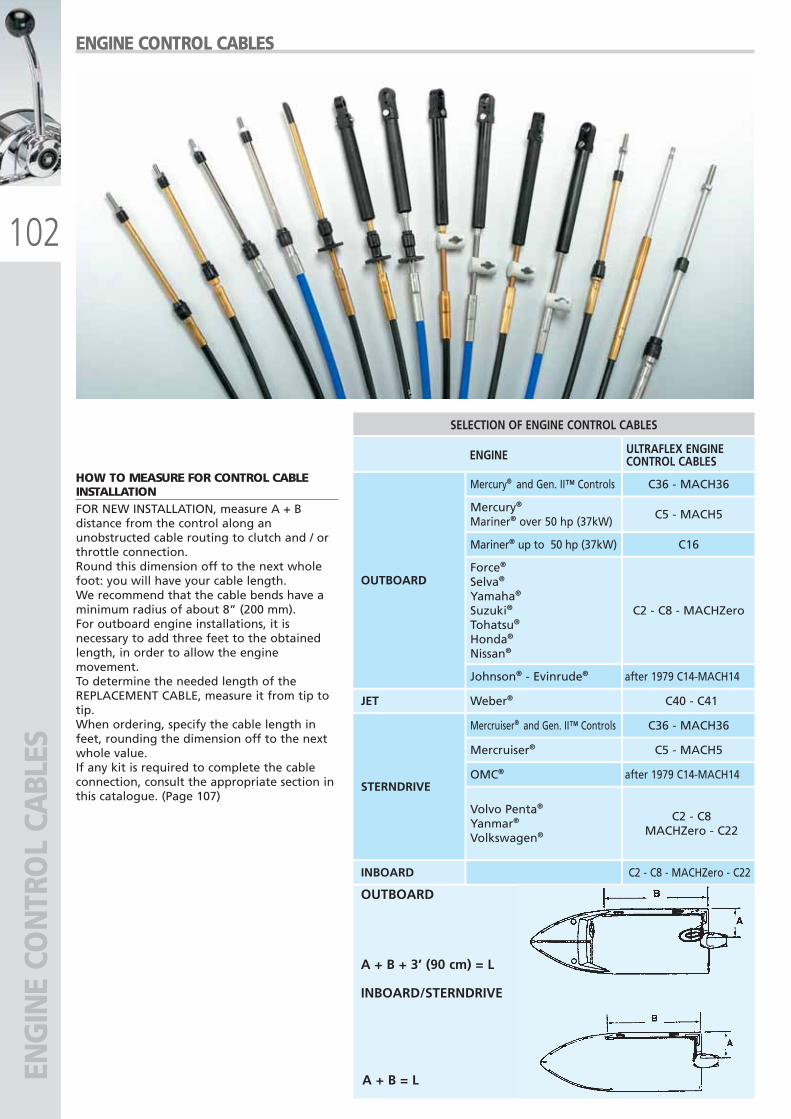
102
OUTBOARD
INBOARD/STERNDRIVE
A + B + 3’ (90 cm) = L
A + B = L
SELECTION OF ENGINE CONTROL CABLES
ENGINE ULTRAFLEX ENGINECONTROL CABLES
OUTBOARD
Mercury®
Mariner® over 50 hp (37kW)C5 - MACH5
STERNDRIVE
Mercruiser®
Mercruiser® and Gen. II™ Controls
Mercury® and Gen. II™ Controls
C5 - MACH5
C36 - MACH36
C36 - MACH36
INBOARD C2 - C8 - MACHZero - C22
JET Weber® C40 - C41
OMC® after 1979 C14-MACH14
Volvo Penta®
Yanmar®
Volkswagen®
C2 - C8MACHZero - C22
Mariner® up to 50 hp (37kW) C16
Force®
Selva®
Yamaha®
Suzuki®
Tohatsu®
Honda®
Nissan®
C2 - C8 - MACHZero
Johnson® - Evinrude® after 1979 C14-MACH14
ENG
INE
CON
TRO
L CA
BLES
HOW TO MEASURE FOR CONTROL CABLEINSTALLATIONFOR NEW INSTALLATION, measure A + Bdistance from the control along anunobstructed cable routing to clutch and / orthrottle connection. Round this dimension off to the next wholefoot: you will have your cable length.We recommend that the cable bends have aminimum radius of about 8” (200 mm).For outboard engine installations, it isnecessary to add three feet to the obtainedlength, in order to allow the enginemovement.To determine the needed length of theREPLACEMENT CABLE, measure it from tip totip.When ordering, specify the cable length infeet, rounding the dimension off to the nextwhole value.If any kit is required to complete the cableconnection, consult the appropriate section inthis catalogue. (Page 107)
ENGINE CONTROL CABLES
ULTRAFLEX2010-Ita:ULTRAFLEX2009-Ita.qxd 18/09/09 17:07 Pagina 102
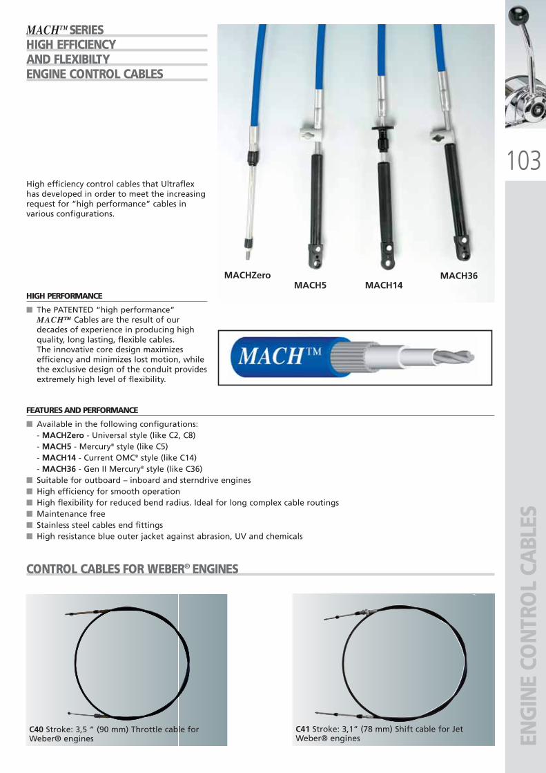
103
MACHZeroMACH14MACH5
MACH36
C40 Stroke: 3,5 “ (90 mm) Throttle cable forWeber® engines EN
GIN
E CO
NTR
OL
CABL
ES
MACHTM SERIESHIGH EFFICIENCYAND FLEXIBILTYENGINE CONTROL CABLES
HIGH PERFORMANCE
■ The PATENTED “high performance”MACH™ Cables are the result of ourdecades of experience in producing highquality, long lasting, flexible cables.The innovative core design maximizesefficiency and minimizes lost motion, whilethe exclusive design of the conduit providesextremely high level of flexibility.
FEATURES AND PERFORMANCE
■ Available in the following configurations:- MACHZero - Universal style (like C2, C8)- MACH5 - Mercury® style (like C5)- MACH14 - Current OMC® style (like C14)- MACH36 - Gen II Mercury® style (like C36)
■ Suitable for outboard – inboard and sterndrive engines■ High efficiency for smooth operation■ High flexibility for reduced bend radius. Ideal for long complex cable routings■ Maintenance free■ Stainless steel cables end fittings■ High resistance blue outer jacket against abrasion, UV and chemicals
High efficiency control cables that Ultraflexhas developed in order to meet the increasingrequest for “high performance” cables invarious configurations.
CONTROL CABLES FOR WEBER® ENGINES
C41 Stroke: 3,1” (78 mm) Shift cable for JetWeber® engines
ULTRAFLEX2010-Ita:ULTRAFLEX2009-Ita.qxd 21/09/09 16:26 Pagina 103
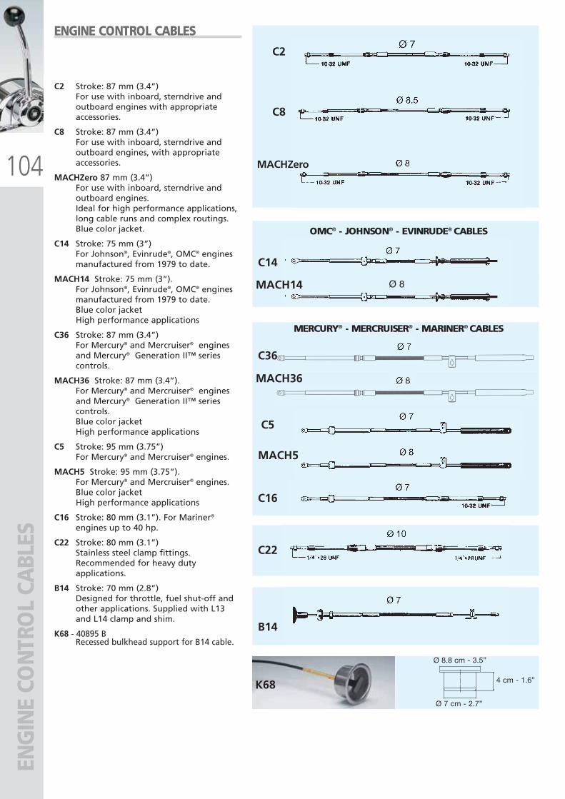
104
B14
K68
C22
C2
C8
MACHZero
C14
MACH14
MACH36
C5
MACH5
C36
C16
Ø 8
Ø 8.8 cm - 3.5”
4 cm - 1.6”
Ø 7 cm - 2.7”
ENG
INE
CON
TRO
L CA
BLES
C2 Stroke: 87 mm (3.4”)For use with inboard, sterndrive andoutboard engines with appropriateaccessories.
C8 Stroke: 87 mm (3.4”)For use with inboard, sterndrive andoutboard engines, with appropriateaccessories.
MACHZero 87 mm (3.4”) For use with inboard, sterndrive andoutboard engines.Ideal for high performance applications,long cable runs and complex routings.Blue color jacket.
C14 Stroke: 75 mm (3”)For Johnson®, Evinrude®, OMC® enginesmanufactured from 1979 to date.
MACH14 Stroke: 75 mm (3”).For Johnson®, Evinrude®, OMC® enginesmanufactured from 1979 to date.Blue color jacketHigh performance applications
C36 Stroke: 87 mm (3.4”)For Mercury® and Mercruiser® enginesand Mercury® Generation II™ seriescontrols.
MACH36 Stroke: 87 mm (3.4”).For Mercury® and Mercruiser® enginesand Mercury® Generation II™ seriescontrols.Blue color jacketHigh performance applications
C5 Stroke: 95 mm (3.75”)For Mercury® and Mercruiser® engines.
MACH5 Stroke: 95 mm (3.75”).For Mercury® and Mercruiser® engines.Blue color jacketHigh performance applications
C16 Stroke: 80 mm (3.1”). For Mariner®
engines up to 40 hp.
C22 Stroke: 80 mm (3.1”)Stainless steel clamp fittings.Recommended for heavy dutyapplications.
B14 Stroke: 70 mm (2.8”)Designed for throttle, fuel shut-off andother applications. Supplied with L13and L14 clamp and shim.
K68 - 40895 BRecessed bulkhead support for B14 cable.
ENGINE CONTROL CABLES
OMC® - JOHNSON® - EVINRUDE® CABLES
MERCURY® - MERCRUISER® - MARINER® CABLES
ULTRAFLEX2010-Ita:ULTRAFLEX2009-Ita.qxd 18/09/09 17:07 Pagina 104
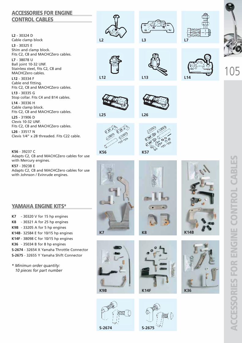
105
L2 L3 L7
L12 L13 L14
L25 L26
K56 K57
S-2674 S-2675
K7 K8
K9B
K14B
K14F K36
ACC
ESSO
RIES
FO
R EN
GIN
E CO
NTR
OL
CABL
ES
L2 - 30324 DCable clamp block
L3 - 30325 EShim and clamp block.Fits C2, C8 and MACHCZero cables.
L7 - 38078 UBall joint 10-32 UNF. Stainless steel, fits C2, C8 andMACHCZero cables.
L12 - 30334 FCable end fitting. Fits C2, C8 and MACHCZero cables.
L13 - 30335 GStop collar. Fits C4 and B14 cables.
L14 - 30336 HCable clamp block. Fits C2, C8 and MACHCZero cables.
L25 - 31906 DClevis 10-32 UNF. Fits C2, C8 and MACHCZero cables.
L26 - 33517 NClevis 1/4” x 28 threaded. Fits C22 cable.
K56 - 39237 CAdapts C2, C8 and MACHCZero cables for usewith Mercury engines.
K57 - 39238 EAdapts C2, C8 and MACHCZero cables for usewith Johnson / Evinrude engines.
YAMAHA ENGINE KITS*
K7 - 30320 V for 15 hp engines
K8 - 30321 A for 25 hp engines
K9B - 33205 A for 5 hp engines
K14B - 32584 E for 10/15 hp engines
K14F - 38098 C for 10/15 hp engines
K36 - 35034 B for 8 hp engines
S-2674 - 32654 X Yamaha Throttle Connector
S-2675 - 32655 Y Yamaha Shift Connector
* Minimun order quantity: 10 pieces for part number
ACCESSORIES FOR ENGINECONTROL CABLES
ULTRAFLEX2010-Ita:ULTRAFLEX2009-Ita.qxd 18/09/09 17:08 Pagina 105
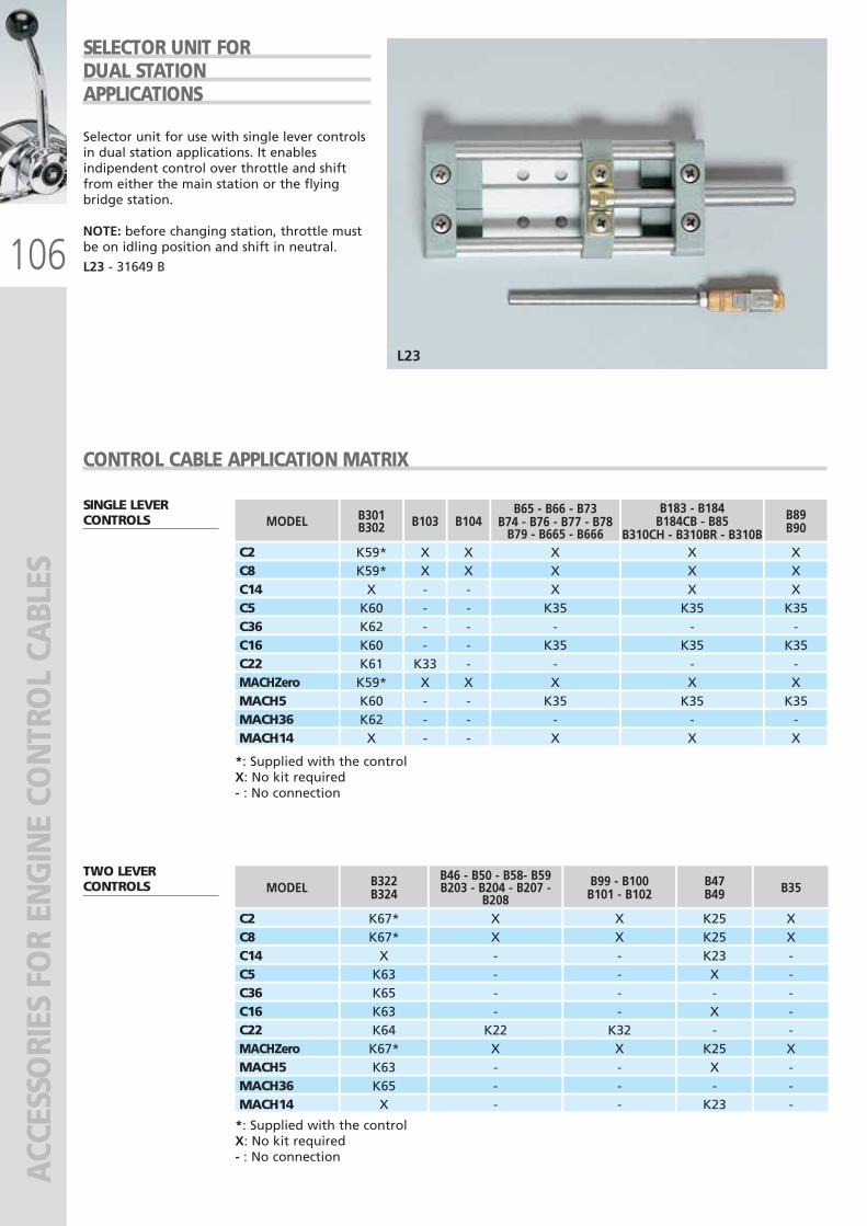
106
L23
C2
MODEL
K59*
B301B302
X
B103
X
B104
X
B65 - B66 - B73B74 - B76 - B77 - B78
B79 - B665 - B666X
B183 - B184B184CB - B85
B310CH - B310BR - B310BX
B89B90
C8 K59* X X X X XC14 X - - X X XC5 K60 - - K35 K35 K35C36 K62 - - - - -C16 K60 - - K35 K35 K35C22 K61 K33 - - - -MACHZero K59* X X X X XMACH5 K60 - - K35 K35 K35MACH36 K62 - - - - -MACH14 X - - X X X
*: Supplied with the controlX: No kit required - : No connection
*: Supplied with the controlX: No kit required - : No connection
SINGLE LEVERCONTROLS
TWO LEVERCONTROLS
C2
MODEL
X
B46 - B50 - B58- B59B203 - B204 - B207 -
B208X
B99 - B100B101 - B102
C8 X XC14 - -C5 - -C36 - -C16 - -C22 K22 K32MACHZero X XMACH5 - -MACH36 - -MACH14 - -
K25
B47B49
XK25 XK23 -X -- -X -- -
K25 XX -- -
K23 -
B35B322B324
K67*K67*
XK63K65K63K64K67*K63K65X
ACC
ESSO
RIES
FO
R EN
GIN
E CO
NTR
OL
CABL
ES
Selector unit for use with single lever controlsin dual station applications. It enablesindipendent control over throttle and shiftfrom either the main station or the flyingbridge station.
NOTE: before changing station, throttle mustbe on idling position and shift in neutral.
L23 - 31649 B
SELECTOR UNIT FORDUAL STATION APPLICATIONS
CONTROL CABLE APPLICATION MATRIX
ULTRAFLEX2010-Ita:ULTRAFLEX2009-Ita.qxd 18/09/09 17:08 Pagina 106
110077
SPA
RE P
ART
SSP
ARE
PA
RTS
ULTRAFLEX2010-Ita:ULTRAFLEX2009-Ita.qxd 18/09/09 17:08 Pagina 107
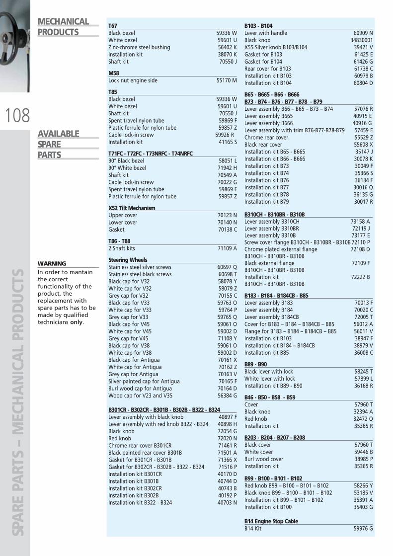
108
SPA
RE P
ART
S –
MEC
HA
NIC
AL
PRO
DU
CTS
WARNINGIn order to mantainthe correctfunctionality of theproduct, thereplacement withspare parts has to bemade by qualifiedtechnicians only.
MECHANICALPRODUCTS
T67Black bezel 59336 WWhite bezel 59601 UZinc-chrome steel bushing 56402 KInstallation kit 38070 KShaft kit 70550 J
M58Lock nut engine side 55170 M
T85Black bezel 59336 WWhite bezel 59601 UShaft kit 70550 JSpent travel nylon tube 59869 FPlastic ferrule for nylon tube 59857 ZCable lock-in screw 59926 RInstallation kit 41165 S
T71FC - T72FC - T73NRFC - T74NRFC90° Black bezel 58051 L90° White bezel 71942 HShaft kit 70549 ACable lock-in screw 70022 GSpent travel nylon tube 59869 FPlastic ferrule for nylon tube 59857 Z
X52 Tilt MechanismUpper cover 70123 NLower cover 70140 NGasket 70138 C
T86 - T882 Shaft kits 71109 A
Steering WheelsStainless steel silver screws 60697 QStainless steel black screws 60698 TBlack cap for V32 58078 YWhite cap for V32 58079 ZGrey cap for V32 70155 CBlack cap for V33 59763 OWhite cap for V33 59764 PGrey cap for V33 59765 QBlack cap for V45 59061 OWhite cap for V45 59002 DGrey cap for V45 71108 YBlack cap for V38 59061 OWhite cap for V38 59002 DBlack cap for Antigua 70161 XWhite cap for Antigua 70162 ZGrey cap for Antigua 70163 VSilver painted cap for Antigua 70165 FBurl wood cap for Antigua 70164 DWood cap for V23 and V35 56384 G
B301CR - B302CR - B301B - B302B - B322 - B324Lever assembly with black knob 40897 F Lever assembly with red knob B322 - B324 40898 H Black knob 72054 G Red knob 72020 N Chrome rear cover B301CR 71461 R Black painted rear cover B301B 71501 A Gasket for B301CR - B301B 71366 X Gasket for B302CR - B302B - B322 - B324 71516 P Installation kit B301CR 40170 D Installation kit B301B 40744 D Installation kit B302CR 40743 B Installation kit B302B 40192 P Installation kit B322 - B324 40703 N
B103 - B104Lever with handle 60909 NBlack knob 34830001X55 Silver knob B103/B104 39421 VGasket for B103 61425 EGasket for B104 61426 GRear cover for B103 61738 CInstallation kit B103 60979 BInstallation kit B104 60804 D
B65 - B665 - B66 - B666 B73 - B74 - B76 - B77 - B78 - B79Lever assembly B66 – B65 – B73 – B74 57076 RLever assembly B665 40915 ELever assembly B666 40916 GLever assembly with trim B76-B77-B78-B79 57459 EChrome rear cover 55529 ZBlack rear cover 55608 XInstallation kit B65 - B665 35147 JInstallation kit B66 - B666 30078 KInstallation kit B73 30049 FInstallation kit B74 35366 SInstallation kit B76 36134 FInstallation kit B77 30016 QInstallation kit B78 36135 GInstallation kit B79 30017 R
B310CH - B310BR - B310BLever assembly B310CH 73158 ALever assembly B310BR 72119 JLever assembly B310B 73177 EScrew cover flange B310CH - B310BR - B310B 72110 PChrome plated external flange 72108 DB310CH - B310BR - B310BBlack external flange 72109 FB310CH - B310BR - B310BInstallation kit 72222 BB310CH - B310BR - B310B
B183 - B184 - B184CB - B85Lever assembly B183 70013 FLever assembly B184 70020 CLever assembly B184CB 72005 TCover for B183 – B184 – B184CB – B85 56012 AFlange for B183 – B184 – B184CB – B85 56011 VInstallation kit B103 38947 FInstallation kit B184 – B184CB 38979 VInstallation kit B85 36008 C
B89 - B90Black lever with lock 58245 TWhite lever with lock 57899 LInstallation kit B89 - B90 36168 R
B46 - B50 - B58 - B59Cover 57960 TBlack knob 32394 ARed knob 32472 QInstallation kit 35365 R
B203 - B204 - B207 - B208Black cover 57960 TWhite cover 59446 BBurl wood cover 38985 PInstallation kit 35365 R
B99 - B100 - B101 - B102Red knob B99 – B100 – B101 – B102 58266 YBlack knob B99 – B100 – B101 – B102 53185 VInstallation kit B99 – B101 – B102 35391 AInstallation kit B100 35403 G
B14 Engine Stop CableB14 Kit 59976 G
AVAILABLESPAREPARTS
ULTRAFLEX2010-Ita:ULTRAFLEX2009-Ita.qxd 18/09/09 17:08 Pagina 108
SilverSteer™ tilt mount helm pumps page 54
Santorini B/S page 76 Control cable for Jet Weber� engines page 103
X70-SVS tilt mechanism for SilverSteer™helm pumps page 54
UP45 - 45 cc helm pumps page 40-43 UP39-SVS page 53
NEW
10
109
SPA
RE P
ART
S –
HYD
RAU
LIC
PRO
DU
CTS
WARNINGIn order to mantainthe correctfunctionality of theproduct, thereplacement withspare parts has to bemade by qualifiedtechnicians only.
HELM PUMPSVented filler plug kit with valve 40801 NNon vented filler plug kit 40800 LShaft seal kit 40875 V
Installation kit for UP20 F 40248 RInstallation kit for UP20 T 39501 TInstallation kit for:
UP25 F/25NV F/28 F/33 F/33NV F/39 F/UP28F-SVS, UP33F-SVS 39476 XInstallation kit for UP25 T/28 T/33 T/39 T 39501 TInstallation kit for UP28 R/33 R/39 R 39500 R
Nylon round flange for X57 70666 ENylon square flange for X64 70670 VChrome plated cover ring - X68 40894 ZPump filling kit 40876 X
UC94-OBF OUTBOARD CYLINDERBlack bull horn mounting bracket 40877 ZThrough tube stainless steel rod 40174 M
Spacer kit 40878 B
UC128-OBF OUTBOARD CYLINDERBlack bull horn mounting bracket 39490 RThrough tube stainless steel rod 39491 T
Spacer kit 41812 ZPlastic cap kit 41810 VUC128 Hardware kit 39979 ATiller arm connecting (ultrabolt) 40822 X(suitable also for UC128-SVS)
UC68-OBS OUTBOARD CYLINDERStainless steel tilt tube extension 39495 B
UC132-OBS OUTBOARD CYLINDERStainless steel tilt tube extension 39495 BExtension rod connecting pin 40917 J
INBOARD CYLINDERSBalljoint for UC69-I 40883 UBalljoint for UC116-I 39477 ZBalljoint for UC168-I and UC215-I 39478 BBalljoint for UC293-I 40178 WBalljoint for UC378-I 41310 Y
Balljoint and shim for UC69-I 40884 WBalljoint and shim for UC116-I 39479 DBalljoint and shim for UC168-I e UC215-I 39480 MBalljoint and shim for UC293-I 40180 GBalljoint and shim for UC378-I 41311 A
STERNDRIVE CYLINDERSExtension rod connecting pin 40917 J
NUT AND SLEEVEBrass nut and sleeve 71004 KNickel plated brass nut and sleeve 71013 L
HYDRAULICPRODUCTS
AVAILABLESPAREPARTS
ULTRAFLEX2010_ENG_Cop+Dorso:ULTRAFLEX2009_ITA_Cop+Dorso.qxd 18/09/09 14:36 Pagina 2