Embed Size (px)
Citation preview

Seville - September 17th, 2010
Ultrasound for Wireless Energy Transferand Communication for Implanted Medical Devices
Francesco MazzilliCatherine Dehollain
Ecole Polytechnique Fédérale de Lausanne (EPFL)RFIC Group
CH-1015 Lausanne, Switzerland

Mazzilli – ESSCIRC 2010 , Workshop - Seville, September 17th, 2010 Slide 2
Outline:
1. Introduction
2. Description of the System
3. In-Vitro Platform
4. Measurements
5. Conclusion
Mazzilli – ESSCIRC 2010 , Workshop - Seville, September 17th, 2010 Slide 3
1. Introduction1.1 Aspects of Implanted Medical Devices1.2 ULTRAsponder Goals
2. Description of the System
3. In-Vitro Platform
4. Measurements
5. Conclusion
Outline:

Mazzilli – ESSCIRC 2010 , Workshop - Seville, September 17th, 2010 Slide 4
• Health care solution.• Partially/totally introduced, surgically/medically,
into the human body.• Remain in the body after the procedure for many
years.• Treat/monitor physiological condition, such as
temperature, pressure, or fluid flow.• Different kinds of IMDs: pacemakers, implantable
cardiac defibrillator (ICD), drug delivery systemsand neurostimulators.
1.1 IMDs Aspects: What is an Implanted Medical Device?

Mazzilli – ESSCIRC 2010 , Workshop - Seville, September 17th, 2010
POTS
GSM
WLAN
CU
CU: External Control Unit: Implanted node
Slide 5
• Continuous monitoring system to help patients lead anormal and healthy life.
• Wireless communication would help monitor patientsduring normal activity.
*source: www.ultrasponder.org
1.2 ULTRAsponder Goals

Mazzilli – ESSCIRC 2010 , Workshop - Seville, September 17th, 2010 Slide 6
2. Description of the System
2.1 Requirements2.2 Why Ultrasound?2.3 Rechargeable battery2.4 Modulator
3. In-Vitro Platform
4. Measurements
5. Conclusion
1. Introduction
Outline:

Mazzilli – ESSCIRC 2010 , Workshop - Seville, September 17th, 2010 Slide 7
IMD deeply and totally introduced into the human body:
• Type of AC Source• Implant Size• Long Term Implant• Long Autonomy• Low-Power Circuitry (Modulator)
2.1 System Requirements

Mazzilli – ESSCIRC 2010 , Workshop - Seville, September 17th, 2010 Slide 8
• To overcome electromagnetic attenuation limit inwater:
• Inherently avoid interference with other medicalsystems (magnetic resonance imaging, pacemaker, …).
Attenuation @ 10-20 cmACOUSTIC 8-16 dB (@ 1 MHz)[1]
RF 60-90 dB (@ 2.45 GHz)[2]
MAGNETIC 50 dB (@ 1 MHz)[2]
[1] Francis A. Duck., Physical Properties of Tissue, 1990.[2] Tomohiro Yamada et al., JJAP, 44(7A), 2005.
2.2 Why Ultrasound?
Mazzilli – ESSCIRC 2010 , Workshop - Seville, September 17th, 2010
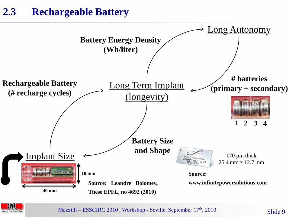
170 µm thick25.4 mm x 12.7 mm
Source:www.infinitepowersolutions.com
Slide 9
Source: Leandre Bolomey,Thèse EPFL, no 4692 (2010)
Long Term Implant(longevity)
Implant Size
Long Autonomy
Rechargeable Battery(# recharge cycles)
Battery Energy Density(Wh/liter)
# batteries(primary + secondary)
Battery Size and Shape
10 mm
40 mm
1 2 3 4
2.3 Rechargeable Battery

Mazzilli – ESSCIRC 2010 , Workshop - Seville, September 17th, 2010 Slide 10
• Backscattering modulation also known asload or impedance modulation.
• Low power ~ µW[3].• Concept is well-known in RF:
1) A continuous or pulsed wave is transmitted from acontrol unit towards a transponder.
2) The transponder reflects the wave back by changing itsload impedance.
3) The received echo at the control unit is demodulated.
[3] Giovanni de Vita et al., JM, 37(7), 2006.
2.4 Modulation Technique

Mazzilli – ESSCIRC 2010 , Workshop - Seville, September 17th, 2010 Slide 11
3. In-Vitro Platform3.1 In-Vitro Before In-Vivo3.2 Overview3.3 Requirements
4. Measurements
5. Conclusion
1. Introduction
2. Description of the System
Outline:

Mazzilli – ESSCIRC 2010 , Workshop - Seville, September 17th, 2010 Slide 12
• Primary analysis of side effects.• Helps in the various design stages of the
IMD.• User requirements (medical doctor, patient)
and system specifications are defined.
3.1 In-Vitro Before In-Vivo

Mazzilli – ESSCIRC 2010 , Workshop - Seville, September 17th, 2010 Slide 13
• Ultrasound energy harvesting (module A)
• Ultrasound wireless communication (module B)
[4] Francesco Mazzilli et al., EMBC, 2010
3.2 Platform Overview[4]
Mazzilli – ESSCIRC 2010 , Workshop - Seville, September 17th, 2010 Slide 14
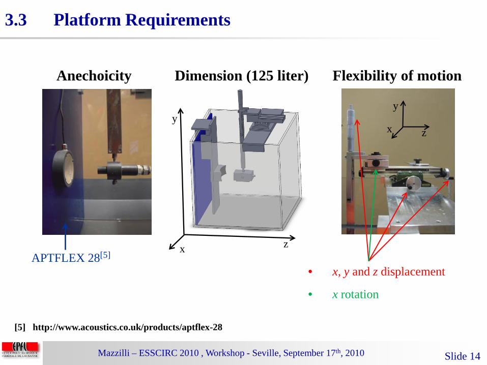
Flexibility of motion
[5] http://www.acoustics.co.uk/products/aptflex-28
Anechoicity Dimension (125 liter)
APTFLEX 28[5]zx
yz
y
x
• x, y and z displacement
• x rotation
3.3 Platform Requirements

Mazzilli – ESSCIRC 2010 , Workshop - Seville, September 17th, 2010 Slide 15
Outline:
4. Measurements4.1 Energy Harvesting4.2 Wireless Communication
5. Conclusion
1. Introduction
2. Description of the System
3. In-Vitro Platform
Mazzilli – ESSCIRC 2010 , Workshop - Seville, September 17th, 2010 Slide 16
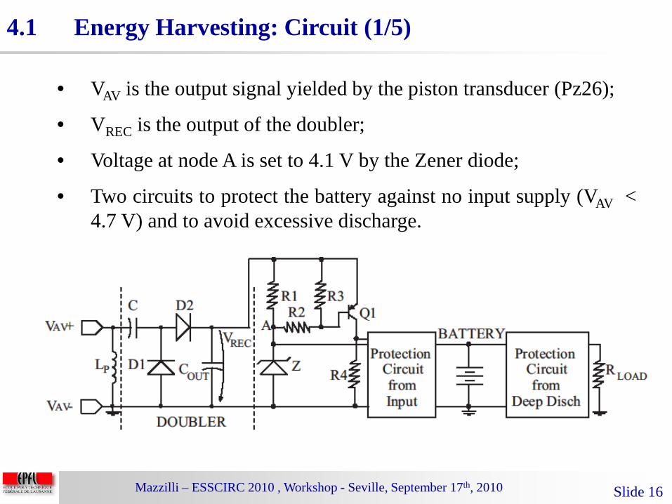
• VAV is the output signal yielded by the piston transducer (Pz26);
• VREC is the output of the doubler;
• Voltage at node A is set to 4.1 V by the Zener diode;
• Two circuits to protect the battery against no input supply (VAV <4.7 V) and to avoid excessive discharge.
4.1 Energy Harvesting: Circuit (1/5)

Mazzilli – ESSCIRC 2010 , Workshop - Seville, September 17th, 2010 Slide 17
• No matching network at the interface between the doubler andthe transducer;
• Lp (ferrite coil) is used to tune out imaginary parts, bothtransducer and input recharging circuits at 1 MHz;
• Lithium Polymer Ion (LIPON) Battery Capacity 300 µAh(manufacturer Infinite Power Solutions).
4.1 Energy Harvesting: Circuit (2/5)
Mazzilli – ESSCIRC 2010 , Workshop - Seville, September 17th, 2010 Slide 18
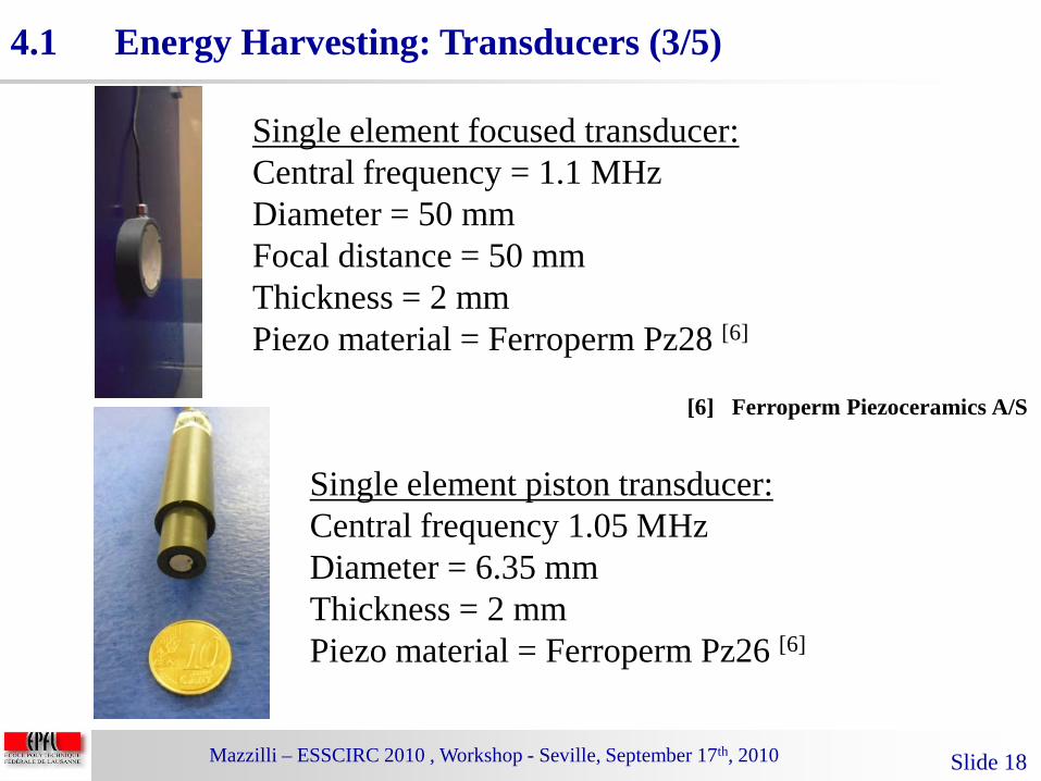
Single element focused transducer:Central frequency = 1.1 MHzDiameter = 50 mmFocal distance = 50 mmThickness = 2 mmPiezo material = Ferroperm Pz28 [6]
Single element piston transducer:Central frequency 1.05 MHzDiameter = 6.35 mmThickness = 2 mmPiezo material = Ferroperm Pz26 [6]
[6] Ferroperm Piezoceramics A/S
4.1 Energy Harvesting: Transducers (3/5)

Mazzilli – ESSCIRC 2010 , Workshop - Seville, September 17th, 2010 Slide 19
• Charging voltage 4.1 V.
• End of charge detected at 4.1 V battery voltage.
4.1 Energy Harvesting: Charge (4/5)
Mazzilli – ESSCIRC 2010 , Workshop - Seville, September 17th, 2010 Slide 20
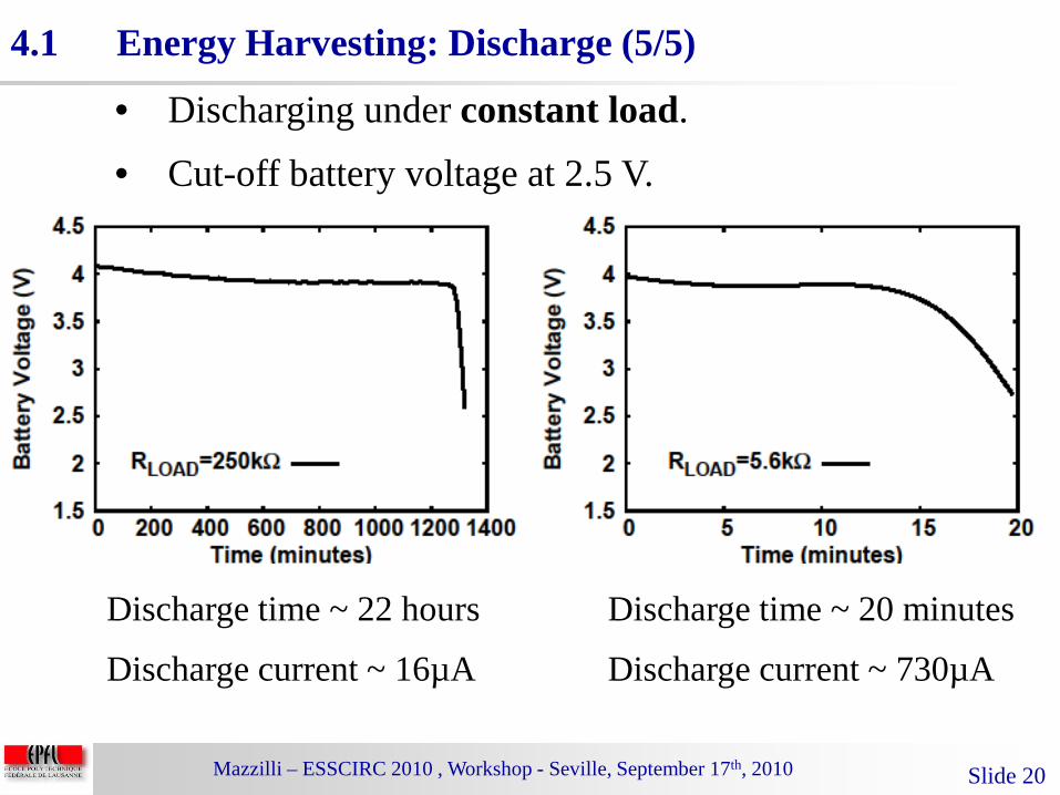
• Discharging under constant load.
• Cut-off battery voltage at 2.5 V.
4.1 Energy Harvesting: Discharge (5/5)
Discharge time ~ 22 hours
Discharge current ~ 16µA
Discharge time ~ 20 minutes
Discharge current ~ 730µA

Mazzilli – ESSCIRC 2010 , Workshop - Seville, September 17th, 2010 Slide 21
• Different pair of transducers.
• An array of elements is used for the control unit (READER),one element is used as transmitter and a second element isused as receiver.
• The transponder (TAG) modulates the incident wave (back-scattering modulation).
• On-Off Keying (OOK) modulation.
• Data rate 20 Kbps.
• The demodulator is present on the READER side, twoamplifiers are used (gain of 20 dB per amplifier) to raise theamplitude of the received wave.
4.2 Wireless Communication: Specifications (1/4)

Mazzilli – ESSCIRC 2010 , Workshop - Seville, September 17th, 2010 Slide 22
Single element piston transducer:Central frequency = 1 MHzDiameter = 13 mmManufacturer IMASONIC
Linear phase array – 64 elements:Central frequency = 1 MHzManufacturer IMASONIC
20 cm
4.2 Wireless Communication: Transducers (2/4)
Mazzilli – ESSCIRC 2010 , Workshop - Seville, September 17th, 2010 Slide 23
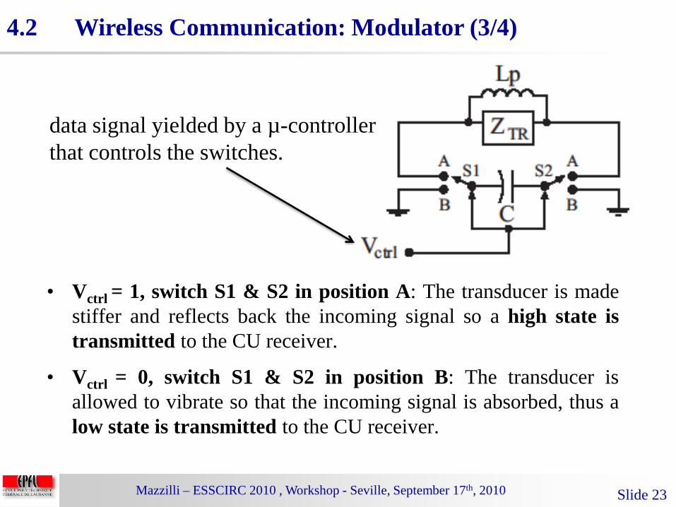
• Vctrl = 1, switch S1 & S2 in position A: The transducer is madestiffer and reflects back the incoming signal so a high state istransmitted to the CU receiver.
• Vctrl = 0, switch S1 & S2 in position B: The transducer isallowed to vibrate so that the incoming signal is absorbed, thus alow state is transmitted to the CU receiver.
4.2 Wireless Communication: Modulator (3/4)
data signal yielded by a µ-controller that controls the switches.

Mazzilli – ESSCIRC 2010 , Workshop - Seville, September 17th, 2010 Slide 24
4.2 Wireless Communication: Results (4/4)
20 cm

Mazzilli – ESSCIRC 2010 , Workshop - Seville, September 17th, 2010 Slide 25
Outline:
5. Conclusion
1. Introduction
2. Description of the System
3. In-Vitro Platform
4. Measurements

Mazzilli – ESSCIRC 2010 , Workshop - Seville, September 17th, 2010 Slide 26
• Platform for in-vitro testing of IMDs.• Energy Harvesting via Ultrasound.• Wireless Communication via Ultrasound.
5 Conclusion

Mazzilli – ESSCIRC 2010 , Workshop - Seville, September 17th, 2010 Slide 27
• Michela Peisino, Giancarlo Corrandini , Eric Meurville (EPFL-LPM2)
• Prakash Thoppay (EPFL, RFIC Group)
• Benjamin Cotté, Cyril Lafon (INSERM)
• Rostand Mitouassiwou, Patric Favre (HEIG-VD)
• Frederic Brochin (IMASONIC)
• European Community’s Seventh FP7 (agreement 224009)
Thanks to:
Acknowledgement

Mazzilli – ESSCIRC 2010 , Workshop - Seville, September 17th, 2010 Slide 28
Thanks !&
Break!
Francesco MazzilliCatherine Dehollain
Ecole Polytechnique Fédérale de Lausanne (EPFL)RFIC Group
CH-1015 Lausanne, [email protected]@epfl.ch