Embed Size (px)
Citation preview

March 2017 DocID026161 Rev 5 1/113
UM1743User manual
STM32CubeF4 demonstration platform
Introduction
The STM32Cube initiative was originated by STMicroelectronics to ease developers’ life by reducing development efforts, time and cost. STM32Cube covers the STM32 portfolio.
The STM32CubeF4 demonstration platform comes on top of the STM32Cube as a firmware package that offers a full set of software components based on a modules architecture that makes it possible to re-use them separately in standalone applications.
All these modules are managed by the STM32CubeF4 demonstration kernel, with the possibility of dynamically add new modules and access the common resources (storage, graphical components and widgets, memory management, Real-Time operating system).
The STM32CubeF4 demonstration platform is built around the powerful graphical library STemWin and the FreeRTOS real time operating system. It uses almost the whole STM32 capability to offer a large scope of usage based on the STM32Cube HAL BSP and several middleware components.
The architecture is defined with the goal of making from the STM32CubeF4 demonstration core an independent central component that can be used with several RTOS and third party firmware libraries, through several abstraction layers inserted between the STM32CubeF4 demonstration core and the modules and libraries working around it.
The STM32CubeF4 demonstration supports STM32F4xx devices and runs on STM324x9I-EVAL,STM324xG-EVAL, STM32F429I-Discovery, STM32446E-EVAL, STM32F479I-EVAL, STM32F469IDISCO, STM32F412G-Discovery and STM32F413H-Discovery boards
www.st.com

Contents UM1743
2/113 DocID026161 Rev 5
Contents
1 STM32Cube overview . . . . . . . . . . . . . . . . . . . . . . . . . . . . . . . . . . . . . . . . 9
2 Global architecture . . . . . . . . . . . . . . . . . . . . . . . . . . . . . . . . . . . . . . . . . 10
3 Kernel description . . . . . . . . . . . . . . . . . . . . . . . . . . . . . . . . . . . . . . . . . . 11
3.1 Overview . . . . . . . . . . . . . . . . . . . . . . . . . . . . . . . . . . . . . . . . . . . . . . . . . .11
3.2 Kernel initialization . . . . . . . . . . . . . . . . . . . . . . . . . . . . . . . . . . . . . . . . . . 12
3.3 Kernel processes and tasks . . . . . . . . . . . . . . . . . . . . . . . . . . . . . . . . . . . 12
3.4 Kernel graphical aspect . . . . . . . . . . . . . . . . . . . . . . . . . . . . . . . . . . . . . . 13
3.5 ST widget add-ons . . . . . . . . . . . . . . . . . . . . . . . . . . . . . . . . . . . . . . . . . . 16
3.5.1 ST animated icon view . . . . . . . . . . . . . . . . . . . . . . . . . . . . . . . . . . . . . . 16
3.5.2 ST slider skin . . . . . . . . . . . . . . . . . . . . . . . . . . . . . . . . . . . . . . . . . . . . . 17
3.6 Kernel menu management . . . . . . . . . . . . . . . . . . . . . . . . . . . . . . . . . . . . 17
3.7 Modules manager . . . . . . . . . . . . . . . . . . . . . . . . . . . . . . . . . . . . . . . . . . . 20
3.8 Direct open feature . . . . . . . . . . . . . . . . . . . . . . . . . . . . . . . . . . . . . . . . . . 22
3.9 Backup and settings configuration . . . . . . . . . . . . . . . . . . . . . . . . . . . . . . 23
3.10 Storage units . . . . . . . . . . . . . . . . . . . . . . . . . . . . . . . . . . . . . . . . . . . . . . 24
3.11 Clock and date . . . . . . . . . . . . . . . . . . . . . . . . . . . . . . . . . . . . . . . . . . . . . 28
3.12 Memory management . . . . . . . . . . . . . . . . . . . . . . . . . . . . . . . . . . . . . . . 29
3.13 Demonstration repository . . . . . . . . . . . . . . . . . . . . . . . . . . . . . . . . . . . . . 31
3.14 Kernel components . . . . . . . . . . . . . . . . . . . . . . . . . . . . . . . . . . . . . . . . . 33
3.15 Kernel core files . . . . . . . . . . . . . . . . . . . . . . . . . . . . . . . . . . . . . . . . . . . . 33
3.16 Hardware settings . . . . . . . . . . . . . . . . . . . . . . . . . . . . . . . . . . . . . . . . . . 34
4 How to create a new module . . . . . . . . . . . . . . . . . . . . . . . . . . . . . . . . . 36
4.1 Creating the graphical aspect . . . . . . . . . . . . . . . . . . . . . . . . . . . . . . . . . . 36
4.2 Graphics customization . . . . . . . . . . . . . . . . . . . . . . . . . . . . . . . . . . . . . . 37
4.3 Module implementation . . . . . . . . . . . . . . . . . . . . . . . . . . . . . . . . . . . . . . 37
4.4 Adding a module to the main desktop . . . . . . . . . . . . . . . . . . . . . . . . . . . 38
4.5 Module's direct open . . . . . . . . . . . . . . . . . . . . . . . . . . . . . . . . . . . . . . . . 39
5 Demonstration customization and configuration . . . . . . . . . . . . . . . . 40

DocID026161 Rev 5 3/113
UM1743 Contents
4
5.1 LCD configuration . . . . . . . . . . . . . . . . . . . . . . . . . . . . . . . . . . . . . . . . . . . 40
5.2 Layers management . . . . . . . . . . . . . . . . . . . . . . . . . . . . . . . . . . . . . . . . . 40
5.3 Touchscreen calibration . . . . . . . . . . . . . . . . . . . . . . . . . . . . . . . . . . . . . . 41
5.4 BSP customization . . . . . . . . . . . . . . . . . . . . . . . . . . . . . . . . . . . . . . . . . . 42
5.4.1 SDRAM configuration . . . . . . . . . . . . . . . . . . . . . . . . . . . . . . . . . . . . . . 42
5.4.2 Touch screen configuration . . . . . . . . . . . . . . . . . . . . . . . . . . . . . . . . . . 43
6 Performance . . . . . . . . . . . . . . . . . . . . . . . . . . . . . . . . . . . . . . . . . . . . . . 45
6.1 Multi buffering features . . . . . . . . . . . . . . . . . . . . . . . . . . . . . . . . . . . . . . . 45
6.2 Multi layers feature . . . . . . . . . . . . . . . . . . . . . . . . . . . . . . . . . . . . . . . . . . 45
6.3 Hardware acceleration . . . . . . . . . . . . . . . . . . . . . . . . . . . . . . . . . . . . . . . 46
7 Footprint . . . . . . . . . . . . . . . . . . . . . . . . . . . . . . . . . . . . . . . . . . . . . . . . . . 48
7.1 Kernel footprint . . . . . . . . . . . . . . . . . . . . . . . . . . . . . . . . . . . . . . . . . . . . . 48
7.2 Module footprint . . . . . . . . . . . . . . . . . . . . . . . . . . . . . . . . . . . . . . . . . . . . 48
7.3 STemWin features resources . . . . . . . . . . . . . . . . . . . . . . . . . . . . . . . . . . 49
7.3.1 JPEG decoder . . . . . . . . . . . . . . . . . . . . . . . . . . . . . . . . . . . . . . . . . . . . 49
7.3.2 GUI components . . . . . . . . . . . . . . . . . . . . . . . . . . . . . . . . . . . . . . . . . . 49
8 Demonstration functional description (STM324x9I-EVAL, STM324xG-EVAL, STM32F429I-Discovery and STM32446E-EVAL) . . . . . . . . . . . . . . . . . . 52
8.1 Kernel . . . . . . . . . . . . . . . . . . . . . . . . . . . . . . . . . . . . . . . . . . . . . . . . . . . . 52
8.1.1 CPU usage . . . . . . . . . . . . . . . . . . . . . . . . . . . . . . . . . . . . . . . . . . . . . . 53
8.1.2 Kernel log . . . . . . . . . . . . . . . . . . . . . . . . . . . . . . . . . . . . . . . . . . . . . . . . 53
8.1.3 Process viewer . . . . . . . . . . . . . . . . . . . . . . . . . . . . . . . . . . . . . . . . . . . 54
8.2 Modules . . . . . . . . . . . . . . . . . . . . . . . . . . . . . . . . . . . . . . . . . . . . . . . . . . 54
8.2.1 System . . . . . . . . . . . . . . . . . . . . . . . . . . . . . . . . . . . . . . . . . . . . . . . . . . 54
8.2.2 File browser . . . . . . . . . . . . . . . . . . . . . . . . . . . . . . . . . . . . . . . . . . . . . . 57
8.2.3 Game . . . . . . . . . . . . . . . . . . . . . . . . . . . . . . . . . . . . . . . . . . . . . . . . . . . 59
8.2.4 Benchmark . . . . . . . . . . . . . . . . . . . . . . . . . . . . . . . . . . . . . . . . . . . . . . . 60
8.2.5 Audio . . . . . . . . . . . . . . . . . . . . . . . . . . . . . . . . . . . . . . . . . . . . . . . . . . . 60
8.2.6 Video . . . . . . . . . . . . . . . . . . . . . . . . . . . . . . . . . . . . . . . . . . . . . . . . . . . 64
8.2.7 USB mass storage device (USBD) . . . . . . . . . . . . . . . . . . . . . . . . . . . . 70
8.2.8 Camera . . . . . . . . . . . . . . . . . . . . . . . . . . . . . . . . . . . . . . . . . . . . . . . . . 72
8.2.9 Image viewer . . . . . . . . . . . . . . . . . . . . . . . . . . . . . . . . . . . . . . . . . . . . . 74

Contents UM1743
4/113 DocID026161 Rev 5
9 Demonstration functional description (STM32F479I-EVAL and STM32F469I-DISCO) . . . . . . . . . . . . . . . . . . . . 77
9.1 Modules . . . . . . . . . . . . . . . . . . . . . . . . . . . . . . . . . . . . . . . . . . . . . . . . . . 77
9.1.1 Audio . . . . . . . . . . . . . . . . . . . . . . . . . . . . . . . . . . . . . . . . . . . . . . . . . . . 77
9.1.2 Video . . . . . . . . . . . . . . . . . . . . . . . . . . . . . . . . . . . . . . . . . . . . . . . . . . . 81
9.1.3 Audio recorder . . . . . . . . . . . . . . . . . . . . . . . . . . . . . . . . . . . . . . . . . . . . 89
9.1.4 VNC server . . . . . . . . . . . . . . . . . . . . . . . . . . . . . . . . . . . . . . . . . . . . . . 92
9.1.5 Game . . . . . . . . . . . . . . . . . . . . . . . . . . . . . . . . . . . . . . . . . . . . . . . . . . . 97
9.1.6 Garden control . . . . . . . . . . . . . . . . . . . . . . . . . . . . . . . . . . . . . . . . . . . . 97
9.1.7 Home alarm . . . . . . . . . . . . . . . . . . . . . . . . . . . . . . . . . . . . . . . . . . . . . . 97
9.1.8 System information . . . . . . . . . . . . . . . . . . . . . . . . . . . . . . . . . . . . . . . . 98
10 Demonstration functional description (STM32F412G-DISCO and STM32F413H-DISCO) . . . . . . . . . . . . . . . . . 99
10.1 Modules . . . . . . . . . . . . . . . . . . . . . . . . . . . . . . . . . . . . . . . . . . . . . . . . . . 99
10.1.1 Audio player . . . . . . . . . . . . . . . . . . . . . . . . . . . . . . . . . . . . . . . . . . . . . . 99
10.1.2 Audio recorder . . . . . . . . . . . . . . . . . . . . . . . . . . . . . . . . . . . . . . . . . . . 102
10.1.3 Video module . . . . . . . . . . . . . . . . . . . . . . . . . . . . . . . . . . . . . . . . . . . . 104
10.1.4 Analog clock module . . . . . . . . . . . . . . . . . . . . . . . . . . . . . . . . . . . . . . 106
10.1.5 USB devices module . . . . . . . . . . . . . . . . . . . . . . . . . . . . . . . . . . . . . . 107
10.1.6 System information . . . . . . . . . . . . . . . . . . . . . . . . . . . . . . . . . . . . . . . 108
11 Revision history . . . . . . . . . . . . . . . . . . . . . . . . . . . . . . . . . . . . . . . . . . 110

DocID026161 Rev 5 5/113
UM1743 List of tables
5
List of tables
Table 1. File system interface: physical storage control functions . . . . . . . . . . . . . . . . . . . . . . . . . . 25Table 2. File system interface APIs . . . . . . . . . . . . . . . . . . . . . . . . . . . . . . . . . . . . . . . . . . . . . . . . . 25Table 3. APIs from the RTC module. . . . . . . . . . . . . . . . . . . . . . . . . . . . . . . . . . . . . . . . . . . . . . . . . 28Table 4. APIs from the memory manager module . . . . . . . . . . . . . . . . . . . . . . . . . . . . . . . . . . . . . . 31Table 5. Kernel components list . . . . . . . . . . . . . . . . . . . . . . . . . . . . . . . . . . . . . . . . . . . . . . . . . . . . 33Table 6. Kernel core files list. . . . . . . . . . . . . . . . . . . . . . . . . . . . . . . . . . . . . . . . . . . . . . . . . . . . . . . 33Table 7. Jumpers for different demonstration boards . . . . . . . . . . . . . . . . . . . . . . . . . . . . . . . . . . . . 35Table 8. LCD frame buffer locations . . . . . . . . . . . . . . . . . . . . . . . . . . . . . . . . . . . . . . . . . . . . . . . . . 43Table 9. Camera frame buffer locations . . . . . . . . . . . . . . . . . . . . . . . . . . . . . . . . . . . . . . . . . . . . . . 43Table 10. Kernel files footprint . . . . . . . . . . . . . . . . . . . . . . . . . . . . . . . . . . . . . . . . . . . . . . . . . . . . . . 48Table 11. Modules footprint . . . . . . . . . . . . . . . . . . . . . . . . . . . . . . . . . . . . . . . . . . . . . . . . . . . . . . . . 48Table 12. RAM requirements for some JPEG resolutions . . . . . . . . . . . . . . . . . . . . . . . . . . . . . . . . . 49Table 13. MemoSTemWin components memory requirements . . . . . . . . . . . . . . . . . . . . . . . . . . . . . 50Table 14. Widget memory requirements. . . . . . . . . . . . . . . . . . . . . . . . . . . . . . . . . . . . . . . . . . . . . . . 50Table 15. Available settings . . . . . . . . . . . . . . . . . . . . . . . . . . . . . . . . . . . . . . . . . . . . . . . . . . . . . . . . 56Table 16. Data structure for audio . . . . . . . . . . . . . . . . . . . . . . . . . . . . . . . . . . . . . . . . . . . . . . . . . . . 61Table 17. Audio module controls . . . . . . . . . . . . . . . . . . . . . . . . . . . . . . . . . . . . . . . . . . . . . . . . . . . . 63Table 18. Video module controls . . . . . . . . . . . . . . . . . . . . . . . . . . . . . . . . . . . . . . . . . . . . . . . . . . . . 65Table 19. Batch files description. . . . . . . . . . . . . . . . . . . . . . . . . . . . . . . . . . . . . . . . . . . . . . . . . . . . . 68Table 20. Variables description . . . . . . . . . . . . . . . . . . . . . . . . . . . . . . . . . . . . . . . . . . . . . . . . . . . . . 69Table 21. Parameters description. . . . . . . . . . . . . . . . . . . . . . . . . . . . . . . . . . . . . . . . . . . . . . . . . . . . 69Table 22. Data structure for USBD module . . . . . . . . . . . . . . . . . . . . . . . . . . . . . . . . . . . . . . . . . . . . 71Table 23. USBD module controls . . . . . . . . . . . . . . . . . . . . . . . . . . . . . . . . . . . . . . . . . . . . . . . . . . . . 71Table 24. Camera module controls. . . . . . . . . . . . . . . . . . . . . . . . . . . . . . . . . . . . . . . . . . . . . . . . . . . 74Table 25. Image viewer module controls . . . . . . . . . . . . . . . . . . . . . . . . . . . . . . . . . . . . . . . . . . . . . . 76Table 26. Image viewer module controls . . . . . . . . . . . . . . . . . . . . . . . . . . . . . . . . . . . . . . . . . . . . . . 80Table 27. Video module controls . . . . . . . . . . . . . . . . . . . . . . . . . . . . . . . . . . . . . . . . . . . . . . . . . . . . 85Table 28. Batch file description. . . . . . . . . . . . . . . . . . . . . . . . . . . . . . . . . . . . . . . . . . . . . . . . . . . . . . 87Table 29. Variable description . . . . . . . . . . . . . . . . . . . . . . . . . . . . . . . . . . . . . . . . . . . . . . . . . . . . . . 88Table 30. Parameters description. . . . . . . . . . . . . . . . . . . . . . . . . . . . . . . . . . . . . . . . . . . . . . . . . . . . 88Table 31. Audio module controls . . . . . . . . . . . . . . . . . . . . . . . . . . . . . . . . . . . . . . . . . . . . . . . . . . . . 91Table 32. VNC server module controls . . . . . . . . . . . . . . . . . . . . . . . . . . . . . . . . . . . . . . . . . . . . . . . . 96Table 33. Audio player module controls . . . . . . . . . . . . . . . . . . . . . . . . . . . . . . . . . . . . . . . . . . . . . . 101Table 34. Audio player module voice controls . . . . . . . . . . . . . . . . . . . . . . . . . . . . . . . . . . . . . . . . . 101Table 35. Audio recorder module controls . . . . . . . . . . . . . . . . . . . . . . . . . . . . . . . . . . . . . . . . . . . . 104Table 36. Document revision history . . . . . . . . . . . . . . . . . . . . . . . . . . . . . . . . . . . . . . . . . . . . . . . . 110

List of figures UM1743
6/113 DocID026161 Rev 5
List of figures
Figure 1. STM32Cube block diagram . . . . . . . . . . . . . . . . . . . . . . . . . . . . . . . . . . . . . . . . . . . . . . . . . 9Figure 2. STM32Cube architecture . . . . . . . . . . . . . . . . . . . . . . . . . . . . . . . . . . . . . . . . . . . . . . . . . . 10Figure 3. Kernel components and services . . . . . . . . . . . . . . . . . . . . . . . . . . . . . . . . . . . . . . . . . . . . 11Figure 4. Startup window . . . . . . . . . . . . . . . . . . . . . . . . . . . . . . . . . . . . . . . . . . . . . . . . . . . . . . . . . . 13Figure 5. Startup window for STM32446E-EVAL, STM32F479I-EVAL,
STM32F469I-DISCO, STM32F412G-DISCO and STM32F413H-DISCO demonstrations. 14Figure 6. Main desktop window . . . . . . . . . . . . . . . . . . . . . . . . . . . . . . . . . . . . . . . . . . . . . . . . . . . . . 14Figure 7. Main desktop window for STM32446E-EVAL demonstration . . . . . . . . . . . . . . . . . . . . . . . 15Figure 8. Main desktop window for STM32479I-EVAL demonstration. . . . . . . . . . . . . . . . . . . . . . . . 15Figure 9. Main desktop window for STM32469I-DISCO demonstration . . . . . . . . . . . . . . . . . . . . . . 15Figure 10. Main desktop window for STM32412G-DISCO and
STM32413H-DISCO demonstrations . . . . . . . . . . . . . . . . . . . . . . . . . . . . . . . . . . . . . . . . . 16Figure 11. Icon view widget . . . . . . . . . . . . . . . . . . . . . . . . . . . . . . . . . . . . . . . . . . . . . . . . . . . . . . . . . 16Figure 12. Slider skin . . . . . . . . . . . . . . . . . . . . . . . . . . . . . . . . . . . . . . . . . . . . . . . . . . . . . . . . . . . . . . 17Figure 13. Status bar . . . . . . . . . . . . . . . . . . . . . . . . . . . . . . . . . . . . . . . . . . . . . . . . . . . . . . . . . . . . . . 18Figure 14. Status bar for STM32446E-EVAL demonstration . . . . . . . . . . . . . . . . . . . . . . . . . . . . . . . . 18Figure 15. Icon view widget . . . . . . . . . . . . . . . . . . . . . . . . . . . . . . . . . . . . . . . . . . . . . . . . . . . . . . . . . 19Figure 16. Icon view widget for STM32446E-EVAL demonstration . . . . . . . . . . . . . . . . . . . . . . . . . . . 19Figure 17. Functionalities and properties of modules . . . . . . . . . . . . . . . . . . . . . . . . . . . . . . . . . . . . . 21Figure 18. Starting file execution . . . . . . . . . . . . . . . . . . . . . . . . . . . . . . . . . . . . . . . . . . . . . . . . . . . . . 22Figure 19. Starting file execution for STM32446E-EVAL demonstration . . . . . . . . . . . . . . . . . . . . . . . 23Figure 20. Available storage units . . . . . . . . . . . . . . . . . . . . . . . . . . . . . . . . . . . . . . . . . . . . . . . . . . . . 24Figure 21. Software architecture . . . . . . . . . . . . . . . . . . . . . . . . . . . . . . . . . . . . . . . . . . . . . . . . . . . . . 26Figure 22. Detection of storage units . . . . . . . . . . . . . . . . . . . . . . . . . . . . . . . . . . . . . . . . . . . . . . . . . . 27Figure 23. Detection of storage units for STM32446E-EVAL demonstration. . . . . . . . . . . . . . . . . . . . 27Figure 24. Setting the time and the date . . . . . . . . . . . . . . . . . . . . . . . . . . . . . . . . . . . . . . . . . . . . . . . 29Figure 25. Setting the time and the date for STM32446E-EVAL demonstration . . . . . . . . . . . . . . . . . 29Figure 26. Memory heap for STM32CubeF4 demonstration . . . . . . . . . . . . . . . . . . . . . . . . . . . . . . . . 30Figure 27. Folder structure. . . . . . . . . . . . . . . . . . . . . . . . . . . . . . . . . . . . . . . . . . . . . . . . . . . . . . . . . . 32Figure 28. STM32Cube demonstration boards . . . . . . . . . . . . . . . . . . . . . . . . . . . . . . . . . . . . . . . . . . 34Figure 29. GUI Builder overview . . . . . . . . . . . . . . . . . . . . . . . . . . . . . . . . . . . . . . . . . . . . . . . . . . . . . 36Figure 30. Graphics customization . . . . . . . . . . . . . . . . . . . . . . . . . . . . . . . . . . . . . . . . . . . . . . . . . . . 37Figure 31. Direct open from file browser . . . . . . . . . . . . . . . . . . . . . . . . . . . . . . . . . . . . . . . . . . . . . . . 39Figure 32. LCDConf location . . . . . . . . . . . . . . . . . . . . . . . . . . . . . . . . . . . . . . . . . . . . . . . . . . . . . . . . 40Figure 33. k_calibration.c location . . . . . . . . . . . . . . . . . . . . . . . . . . . . . . . . . . . . . . . . . . . . . . . . . . . . 41Figure 34. Calibration steps . . . . . . . . . . . . . . . . . . . . . . . . . . . . . . . . . . . . . . . . . . . . . . . . . . . . . . . . . 42Figure 35. SDRAM initialization . . . . . . . . . . . . . . . . . . . . . . . . . . . . . . . . . . . . . . . . . . . . . . . . . . . . . . 43Figure 36. Touch screen initialization . . . . . . . . . . . . . . . . . . . . . . . . . . . . . . . . . . . . . . . . . . . . . . . . . 44Figure 37. Example of tearing effect . . . . . . . . . . . . . . . . . . . . . . . . . . . . . . . . . . . . . . . . . . . . . . . . . . 45Figure 38. Independent layer management . . . . . . . . . . . . . . . . . . . . . . . . . . . . . . . . . . . . . . . . . . . . . 46Figure 39. CPU usage display . . . . . . . . . . . . . . . . . . . . . . . . . . . . . . . . . . . . . . . . . . . . . . . . . . . . . . . 52Figure 40. CPU usage . . . . . . . . . . . . . . . . . . . . . . . . . . . . . . . . . . . . . . . . . . . . . . . . . . . . . . . . . . . . . 53Figure 41. Example of Log messages . . . . . . . . . . . . . . . . . . . . . . . . . . . . . . . . . . . . . . . . . . . . . . . . . 53Figure 42. Process viewer . . . . . . . . . . . . . . . . . . . . . . . . . . . . . . . . . . . . . . . . . . . . . . . . . . . . . . . . . . 54Figure 43. Demonstration global information . . . . . . . . . . . . . . . . . . . . . . . . . . . . . . . . . . . . . . . . . . . . 55Figure 44. Demonstration general settings . . . . . . . . . . . . . . . . . . . . . . . . . . . . . . . . . . . . . . . . . . . . . 55Figure 45. Clock setting . . . . . . . . . . . . . . . . . . . . . . . . . . . . . . . . . . . . . . . . . . . . . . . . . . . . . . . . . . . . 56Figure 46. File browser . . . . . . . . . . . . . . . . . . . . . . . . . . . . . . . . . . . . . . . . . . . . . . . . . . . . . . . . . . . . 57

DocID026161 Rev 5 7/113
UM1743 List of figures
8
Figure 47. File browser module architecture . . . . . . . . . . . . . . . . . . . . . . . . . . . . . . . . . . . . . . . . . . . . 58Figure 48. File opening from browser . . . . . . . . . . . . . . . . . . . . . . . . . . . . . . . . . . . . . . . . . . . . . . . . . 58Figure 49. File properties display . . . . . . . . . . . . . . . . . . . . . . . . . . . . . . . . . . . . . . . . . . . . . . . . . . . . . 59Figure 50. Reversi game . . . . . . . . . . . . . . . . . . . . . . . . . . . . . . . . . . . . . . . . . . . . . . . . . . . . . . . . . . . 59Figure 51. Benchmarking. . . . . . . . . . . . . . . . . . . . . . . . . . . . . . . . . . . . . . . . . . . . . . . . . . . . . . . . . . . 60Figure 52. Audio player module architecture . . . . . . . . . . . . . . . . . . . . . . . . . . . . . . . . . . . . . . . . . . . . 61Figure 53. Audio player module startup . . . . . . . . . . . . . . . . . . . . . . . . . . . . . . . . . . . . . . . . . . . . . . . . 62Figure 54. Video player module architecture . . . . . . . . . . . . . . . . . . . . . . . . . . . . . . . . . . . . . . . . . . . . 64Figure 55. Video player module startup . . . . . . . . . . . . . . . . . . . . . . . . . . . . . . . . . . . . . . . . . . . . . . . . 65Figure 56. EMF generation environment . . . . . . . . . . . . . . . . . . . . . . . . . . . . . . . . . . . . . . . . . . . . . . . 67Figure 57. JPEG2Movie overview . . . . . . . . . . . . . . . . . . . . . . . . . . . . . . . . . . . . . . . . . . . . . . . . . . . . 67Figure 58. EMF file generation. . . . . . . . . . . . . . . . . . . . . . . . . . . . . . . . . . . . . . . . . . . . . . . . . . . . . . . 68Figure 59. USBD module architecture . . . . . . . . . . . . . . . . . . . . . . . . . . . . . . . . . . . . . . . . . . . . . . . . . 70Figure 60. USBD module startup . . . . . . . . . . . . . . . . . . . . . . . . . . . . . . . . . . . . . . . . . . . . . . . . . . . . . 71Figure 61. Camera module architecture . . . . . . . . . . . . . . . . . . . . . . . . . . . . . . . . . . . . . . . . . . . . . . . 73Figure 62. Camera module startup . . . . . . . . . . . . . . . . . . . . . . . . . . . . . . . . . . . . . . . . . . . . . . . . . . . 73Figure 63. Image viewer architecture. . . . . . . . . . . . . . . . . . . . . . . . . . . . . . . . . . . . . . . . . . . . . . . . . . 75Figure 64. Image viewer startup . . . . . . . . . . . . . . . . . . . . . . . . . . . . . . . . . . . . . . . . . . . . . . . . . . . . . 76Figure 65. Audio player module architecture . . . . . . . . . . . . . . . . . . . . . . . . . . . . . . . . . . . . . . . . . . . . 77Figure 66. Audio player module performance mechanisms. . . . . . . . . . . . . . . . . . . . . . . . . . . . . . . . . 78Figure 67. Start audio player . . . . . . . . . . . . . . . . . . . . . . . . . . . . . . . . . . . . . . . . . . . . . . . . . . . . . . . . 78Figure 68. Adding audio files to the playlist . . . . . . . . . . . . . . . . . . . . . . . . . . . . . . . . . . . . . . . . . . . . . 79Figure 69. Equalizer and loudness frame . . . . . . . . . . . . . . . . . . . . . . . . . . . . . . . . . . . . . . . . . . . . . . 79Figure 70. Background mode. . . . . . . . . . . . . . . . . . . . . . . . . . . . . . . . . . . . . . . . . . . . . . . . . . . . . . . . 79Figure 71. Hardware connectivity . . . . . . . . . . . . . . . . . . . . . . . . . . . . . . . . . . . . . . . . . . . . . . . . . . . . 80Figure 72. Video player module architecture . . . . . . . . . . . . . . . . . . . . . . . . . . . . . . . . . . . . . . . . . . . . 82Figure 73. Video player module performance . . . . . . . . . . . . . . . . . . . . . . . . . . . . . . . . . . . . . . . . . . . 83Figure 74. Start video player . . . . . . . . . . . . . . . . . . . . . . . . . . . . . . . . . . . . . . . . . . . . . . . . . . . . . . . . 83Figure 75. Adding files to the playlist . . . . . . . . . . . . . . . . . . . . . . . . . . . . . . . . . . . . . . . . . . . . . . . . . . 84Figure 76. Warning popup . . . . . . . . . . . . . . . . . . . . . . . . . . . . . . . . . . . . . . . . . . . . . . . . . . . . . . . . . . 84Figure 77. Video is playing. . . . . . . . . . . . . . . . . . . . . . . . . . . . . . . . . . . . . . . . . . . . . . . . . . . . . . . . . . 84Figure 78. Hiding control keys and other information . . . . . . . . . . . . . . . . . . . . . . . . . . . . . . . . . . . . . 85Figure 79. EMF generation format . . . . . . . . . . . . . . . . . . . . . . . . . . . . . . . . . . . . . . . . . . . . . . . . . . . . 86Figure 80. JPEG2Movie overview . . . . . . . . . . . . . . . . . . . . . . . . . . . . . . . . . . . . . . . . . . . . . . . . . . . . 86Figure 81. EMF file generation. . . . . . . . . . . . . . . . . . . . . . . . . . . . . . . . . . . . . . . . . . . . . . . . . . . . . . . 87Figure 82. Audio recorder module architecture . . . . . . . . . . . . . . . . . . . . . . . . . . . . . . . . . . . . . . . . . . 89Figure 83. Audio recorder module startup . . . . . . . . . . . . . . . . . . . . . . . . . . . . . . . . . . . . . . . . . . . . . . 90Figure 84. Start Audio recording . . . . . . . . . . . . . . . . . . . . . . . . . . . . . . . . . . . . . . . . . . . . . . . . . . . . . 90Figure 85. Stop Audio recording . . . . . . . . . . . . . . . . . . . . . . . . . . . . . . . . . . . . . . . . . . . . . . . . . . . . . 90Figure 86. Play the recorded wave file. . . . . . . . . . . . . . . . . . . . . . . . . . . . . . . . . . . . . . . . . . . . . . . . . 91Figure 87. Hardware connectivity . . . . . . . . . . . . . . . . . . . . . . . . . . . . . . . . . . . . . . . . . . . . . . . . . . . . 91Figure 88. Video player module architecture . . . . . . . . . . . . . . . . . . . . . . . . . . . . . . . . . . . . . . . . . . . . 93Figure 89. VNC server module startup . . . . . . . . . . . . . . . . . . . . . . . . . . . . . . . . . . . . . . . . . . . . . . . . 93Figure 90. Enable / Disable secure mode . . . . . . . . . . . . . . . . . . . . . . . . . . . . . . . . . . . . . . . . . . . . . . 94Figure 91. Start VNC server. . . . . . . . . . . . . . . . . . . . . . . . . . . . . . . . . . . . . . . . . . . . . . . . . . . . . . . . . 94Figure 92. IP address assigned . . . . . . . . . . . . . . . . . . . . . . . . . . . . . . . . . . . . . . . . . . . . . . . . . . . . . . 94Figure 93. Run VNC Client . . . . . . . . . . . . . . . . . . . . . . . . . . . . . . . . . . . . . . . . . . . . . . . . . . . . . . . . . 95Figure 94. Background mode. . . . . . . . . . . . . . . . . . . . . . . . . . . . . . . . . . . . . . . . . . . . . . . . . . . . . . . . 95Figure 95. Hardware connectivity . . . . . . . . . . . . . . . . . . . . . . . . . . . . . . . . . . . . . . . . . . . . . . . . . . . . 96Figure 96. Reversi game . . . . . . . . . . . . . . . . . . . . . . . . . . . . . . . . . . . . . . . . . . . . . . . . . . . . . . . . . . . 97Figure 97. Garden control . . . . . . . . . . . . . . . . . . . . . . . . . . . . . . . . . . . . . . . . . . . . . . . . . . . . . . . . . . 97Figure 98. Home alarm . . . . . . . . . . . . . . . . . . . . . . . . . . . . . . . . . . . . . . . . . . . . . . . . . . . . . . . . . . . . 98

List of figures UM1743
8/113 DocID026161 Rev 5
Figure 99. Watching a room. . . . . . . . . . . . . . . . . . . . . . . . . . . . . . . . . . . . . . . . . . . . . . . . . . . . . . . . . 98Figure 100. System information . . . . . . . . . . . . . . . . . . . . . . . . . . . . . . . . . . . . . . . . . . . . . . . . . . . . . . . 98Figure 101. Audio player module architecture . . . . . . . . . . . . . . . . . . . . . . . . . . . . . . . . . . . . . . . . . . . 100Figure 102. Audio player module startup . . . . . . . . . . . . . . . . . . . . . . . . . . . . . . . . . . . . . . . . . . . . . . . 100Figure 103. Board for beam-forming implementation . . . . . . . . . . . . . . . . . . . . . . . . . . . . . . . . . . . . . 102Figure 104. Audio recorder module architecture . . . . . . . . . . . . . . . . . . . . . . . . . . . . . . . . . . . . . . . . . 103Figure 105. Audio recorder module startup . . . . . . . . . . . . . . . . . . . . . . . . . . . . . . . . . . . . . . . . . . . . . 103Figure 106. Audio recorder - Process description . . . . . . . . . . . . . . . . . . . . . . . . . . . . . . . . . . . . . . . . 104Figure 107. Video recorder module architecture . . . . . . . . . . . . . . . . . . . . . . . . . . . . . . . . . . . . . . . . . 105Figure 108. Video recorder module startup . . . . . . . . . . . . . . . . . . . . . . . . . . . . . . . . . . . . . . . . . . . . . 106Figure 109. Analog clock module startup. . . . . . . . . . . . . . . . . . . . . . . . . . . . . . . . . . . . . . . . . . . . . . . 106Figure 110. Analog clock setting . . . . . . . . . . . . . . . . . . . . . . . . . . . . . . . . . . . . . . . . . . . . . . . . . . . . . 107Figure 111. USBD module architecture . . . . . . . . . . . . . . . . . . . . . . . . . . . . . . . . . . . . . . . . . . . . . . . . 107Figure 112. USBD module startup . . . . . . . . . . . . . . . . . . . . . . . . . . . . . . . . . . . . . . . . . . . . . . . . . . . . 108Figure 113. Connection of an USB device. . . . . . . . . . . . . . . . . . . . . . . . . . . . . . . . . . . . . . . . . . . . . . 108Figure 114. System information module startup . . . . . . . . . . . . . . . . . . . . . . . . . . . . . . . . . . . . . . . . . 109

DocID026161 Rev 5 9/113
UM1743 STM32Cube overview
112
1 STM32Cube overview
The STM32Cube initiative was originated by STMicroelectronics to ease developers’ life by reducing development efforts, time and cost. STM32Cube covers the STM32 portfolio.
STM32Cube Version 1.x includes:
• The STM32CubeMX, a graphical software configuration tool that allows to generate C initialization code using graphical wizards.
• A comprehensive embedded software platform, delivered per series (such as STM32CubeF4 for STM32F4 series)
– The STM32CubeF4 HAL, an STM32 abstraction layer embedded software, ensuring maximized portability across STM32 portfolio
– A consistent set of middleware components such as RTOS, USB, TCP/IP, Graphics
– All embedded software utilities coming with a full set of examples.
Figure 1. STM32Cube block diagram

Global architecture UM1743
10/113 DocID026161 Rev 5
2 Global architecture
The STM32CubeF4 demonstration is composed of a central kernel based on a set of firmware and hardware services offered by the STM32Cube middleware and the several evaluation and discovery boards and a set of modules mounted on the kernel and built in a modular architecture. Each module can be reused separately in a standalone application. The full set of modules is managed by the Kernel which provides access to all common resources and facilitates the addition of new modules as shown in Figure 2.
Each module should provide the following functionalities and proprieties:
1. Icon and graphical aspect characteristics.
2. Method to startup the module.
3. Method to close down safety the module (example: Hot unplug for Unit Storage)
4. Method to manage low power mode
5. The module application core ( main module process)
6. Specific configuration
7. Error management
Figure 2. STM32Cube architecture
DocID026161 Rev 5 11/113
UM1743 Kernel description
112
3 Kernel description
3.1 Overview
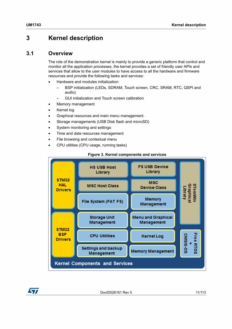
The role of the demonstration kernel is mainly to provide a generic platform that control and monitor all the application processes, the kernel provides a set of friendly user APIs and services that allow to the user modules to have access to all the hardware and firmware resources and provide the following tasks and services:
• Hardware and modules initialization:
– BSP initialization (LEDs, SDRAM, Touch screen, CRC, SRAM, RTC, QSPI and audio)
– GUI initialization and Touch screen calibration
• Memory management
• Kernel log
• Graphical resources and main menu management.
• Storage managements (USB Disk flash and microSD)
• System monitoring and settings
• Time and date resources management
• File browsing and contextual menu
• CPU utilities (CPU usage, running tasks)
Figure 3. Kernel components and services
Kernel description UM1743
12/113 DocID026161 Rev 5
3.2 Kernel initialization
The first task of the kernel is to initialize the hardware and firmware resources to make them available to its internal processes and the modules around it. The kernel starts by initializing the HAL, system clocks and then the hardware resources needed during the middleware components:
• LEDs and Touchscreen
• SDRAM/SRAM
• Backup SRAM
• RTC
• Quad-SPI Flash memory
• Audio Interface
Note: Not all the hardware resources can be used in all demonstration platforms, according to the availability and to the integrated modules.
Once the low level resources are initialized, the kernel performs the STemWin GUI library initialization and prepares the following common services:
• Memory manager
• Storage units
• Modules manager
• Kernel Log
Upon full initialization phase, the kernel adds and links the system and user modules to the demonstration core.
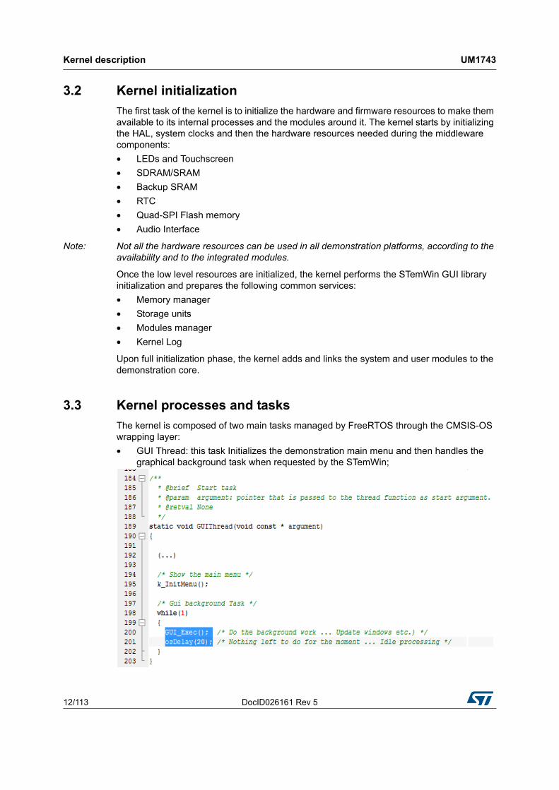
3.3 Kernel processes and tasks
The kernel is composed of two main tasks managed by FreeRTOS through the CMSIS-OS wrapping layer:
• GUI Thread: this task Initializes the demonstration main menu and then handles the graphical background task when requested by the STemWin;

DocID026161 Rev 5 13/113
UM1743 Kernel description
112
• Timer Callback: this is the callback of the Timer managing periodically the touch screen state, the Timer callback is called periodically each 40 milliseconds.
3.4 Kernel graphical aspect
The STM32CubeF4 demonstration is built around the STemWin Graphical Library, based on SEGGER emWin one. STemWin is a professional graphical stack library, enabling Graphical User Interfaces (GUI) building up with any STM32, any LCD and any LCD controller, taking benefit from STM32 hardware accelerations, whenever possible.
The graphical aspect of the STM32CubeF4 demonstration is divided into two main graphical components:
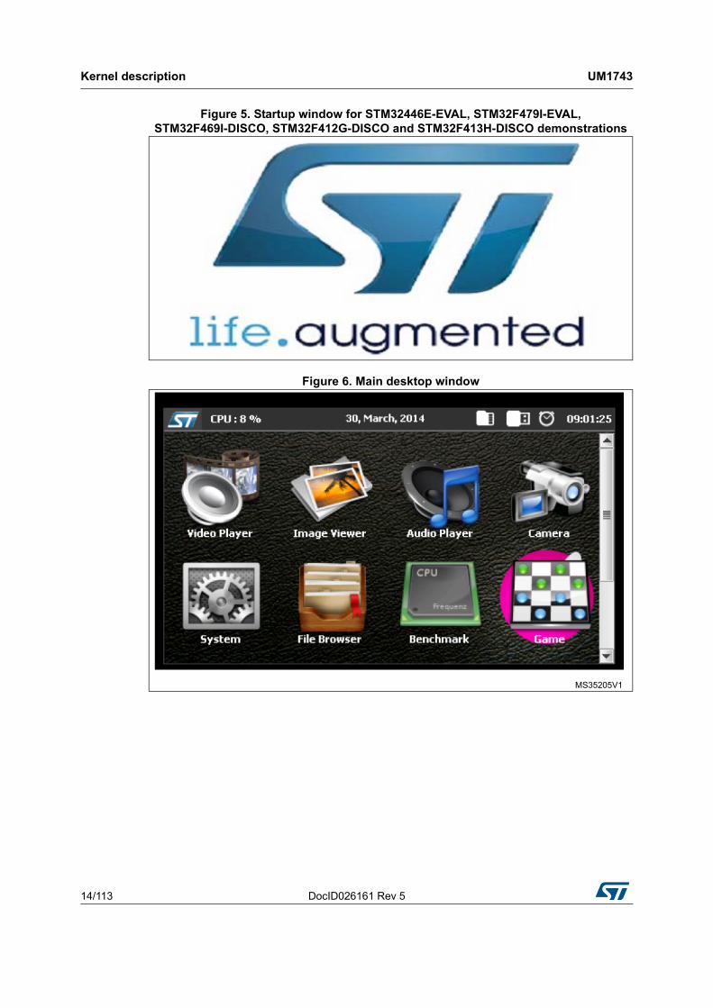
• the startup window (Figure 4 and Figure 5), showing the progress of the hardware and software initialization;
• the main desktop (shown in figures 6, 7, 8 and 9), that handles the main demonstration menu and the many kernel and module controls.
Figure 4. Startup window
Kernel description UM1743
14/113 DocID026161 Rev 5
Figure 5. Startup window for STM32446E-EVAL, STM32F479I-EVAL,STM32F469I-DISCO, STM32F412G-DISCO and STM32F413H-DISCO demonstrations
Figure 6. Main desktop window

DocID026161 Rev 5 15/113
UM1743 Kernel description
112
Figure 7. Main desktop window for STM32446E-EVAL demonstration
Figure 8. Main desktop window for STM32479I-EVAL demonstration
Figure 9. Main desktop window for STM32469I-DISCO demonstration

Kernel description UM1743
16/113 DocID026161 Rev 5
Figure 10. Main desktop window for STM32412G-DISCO andSTM32413H-DISCO demonstrations
3.5 ST widget add-ons
Note: This section is applicable only for STM32F479I-EVAL and STM32F469I-DISCO demonstrations.
The ST_addons binary file provided with STM32F4 demonstration contains new widgets based on STemWin graphical library:
• ST animated icon view
• ST slider skin
3.5.1 ST animated icon view
A new icon view widget is delivered with STM32F4 demonstration based on STemWin graphical library.
The new widget offers the possibility to turn all the modules icons in the menu after startup with a configured number of frames and configured a delay between each frame.
The new icon view (see Figure 11) offers also the possibility to configure the module name with two different colors and fonts.
Figure 11. Icon view widget

DocID026161 Rev 5 17/113
UM1743 Kernel description
112
3.5.2 ST slider skin
A new slider skin is delivered with STM32F4 demonstration based on STemWin graphical library. The new skin offers the possibility to change the slider color and the behavior as shown in Figure 12.
Figure 12. Slider skin
3.6 Kernel menu management
The main demonstration menu is initialized and launched by the GUI thread. Before the initialization of the menu the following actions are performed:
• Draw the background image.
• Create the status bar (not applicable for STM32F479I-EVAL, STM32F469I-DISCO, STM32F412G-DISCO and and STM32F413H-DISCO demonstrations).
• Restore general settings from backup memory.
• Setup the main desktop callback to manage main window messages.
The main desktop is built around two main graphical components:
• The status bar (Figure 13 and Figure 14): indicates the storage units connection status, current time and date and a system button to allow to get system information like (running task, CPU load, and kernel log).
• The icon view widget (Figure 15 and Figure 16): contains the icons associated to added modules. User can launch a module by a simple click on the module icon.

Kernel description UM1743
18/113 DocID026161 Rev 5
Figure 13. Status bar
Figure 14. Status bar for STM32446E-EVAL demonstration

DocID026161 Rev 5 19/113
UM1743 Kernel description
112
Figure 15. Icon view widget
Figure 16. Icon view widget for STM32446E-EVAL demonstration
A module is launched on simple click on the associated icon by calling to the startup function in the module structure; this is done when a WM_NOTIFICATION_RELEASED message arrives to the desktop callback with ID_ICONVIEW_MENU:

Kernel description UM1743
20/113 DocID026161 Rev 5
3.7 Modules manager
The modules are managed by the kernel; the latter is responsible of initializing the modules, initializing hardware and GUI resources relative to the modules and initializing the common resources such as the storage Unit, the graphical widgets and the system menu.
Each module should provide the following functionalities and proprieties:
1. Icon and graphical component structure.
2. Method to startup the module.
3. Method to close down safety the module (example: Hot unplug for MS flash disk)
4. Method to manage low power mode (optional)
5. The Application task
6. The module background process (optional)
7. Remote control method (optional)
8. Specific configuration
9. Error management

DocID026161 Rev 5 21/113
UM1743 Kernel description
112
Figure 17. Functionalities and properties of modules
The modules could be added in run time to the demonstration and can use the common kernel resources. The following code shows how to add a module to the demonstration:
A module is a set of function and data structures that are defined in a data structure that provides all the information and pointers to specific methods and functions to the kernel. This later checks the integrity and the validity of the module and inserts its structure into a module table.
Each module is identified by a unique ID. When two modules have the same UID, the Kernel rejects the second one. The module structure is defined as follows:

Kernel description UM1743
22/113 DocID026161 Rev 5
In this definition:
• Id: unique module identifier.
• Name: pointer to module name
• Icon: pointer to module icon (bitmap format)
• Startup: the function that create the module frame and control buttons
• DirectOpen: the function that creates the module frame and launch the media associated to the file name selected in the file browser linked to a specific file extension (note that this functionality is not used in STM32F479I-EVAL; STM32F469I-DISCO, STM32F412G-DISCO and STM32F413H-DISCO demonstrations).
3.8 Direct open feature
The direct open feature allows the user to launch a media module directly from file browser when the extension file match with supported media type. The file extension should be previously associated to a module by using the following code:
For STM32446E-EVAL we have:
When the file browser is opened, a simple click on a file will open a contextual menu, that direct file open can be executed, as shown in Figure 18 and in Figure 19.
Figure 18. Starting file execution
DocID026161 Rev 5 23/113
UM1743 Kernel description
112
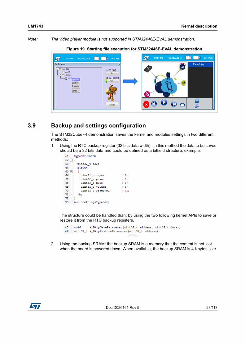
Note: The video player module is not supported in STM32446E-EVAL demonstration.
Figure 19. Starting file execution for STM32446E-EVAL demonstration
3.9 Backup and settings configuration
The STM32CubeF4 demonstration saves the kernel and modules settings in two different methods:
1. Using the RTC backup register (32 bits data width) , in this method the data to be saved should be a 32 bits data and could be defined as a bitfield structure, example:
The structure could be handled than, by using the two following kernel APIs to save or restore it from the RTC backup registers.
2. Using the backup SRAM: the backup SRAM is a memory that the content is not lost when the board is powered down. When available, the backup SRAM is 4 Kbytes size

Kernel description UM1743
24/113 DocID026161 Rev 5
and located at address: BKPSRAM_BASE (0x40024000). The backup SRAM could be used as normal RAM to save file paths or big structure example:
3.10 Storage units
The STM32CubeF4 demonstration kernel offers two storage units that can be used to retrieve audio, Image and Video media or to save captured images from the camera (Figure 20).
Figure 20. Available storage units
The two units are initialized during the platform startup and thus they are available to all the modules during the STM32CubeF4 demonstration run time. These two units are accessible through the standard I/O operations offered by the FatFS used in the development platform. The USB Disk flash unit is identified as the Unit 0 and available only if a USB disk flash is connected on the USB FS connector, while the microSD flash is identified as the Unit1 and available only if the microSD card is connected. The units are mounted automatically when the physical media are connected to the connector on the board.

DocID026161 Rev 5 25/113
UM1743 Kernel description
112
The implemented functions in the file system interface to deal with the physical storage units are summarized in Table 1.
The full APIs functions set given by the file system interface are listed in Table 2:
Table 1. File system interface: physical storage control functions
Function Description
disk_initialize Initialize disk drive
disk_read Interface function for a logical page read
disk_write Interface function for a logical page write
disk_status Interface function for testing if unit is ready
disk_ioct Control device dependent features
Table 2. File system interface APIs
Function Description
f_mount Register/Unregister a work area
f_open Open/Create a file
f_close Close a file
f_read Read file
f_write Write file
f_lseek Move read/write pointer, Expand file size
f_truncate Truncate file size
f_sync Flush cached data
f_opendir Open a directory
f_readdir Read a directory item
f_getfree Get free clusters
f_stat Get file status
f_mkdir Create a directory
f_unlink Remove a file or directory
f_chmod Change attribute
f_utime Change timestamp
f_rename Rename/Move a file or directory
f_mkfs Create a file system on the drive
f_forward Forward file data to the stream directly
f_chdir Change current directory
f_chdrive Change current drive
f_getcwd Retrieve the current directory
f_gets Read a string

Kernel description UM1743
26/113 DocID026161 Rev 5
For the FAT FS file system, the page size is fixed to 512 bytes. USB Flash disks with higher page size are not supported.
The Storage units are built around the USB host library in high speed and the microSD BSP drivers; the software architecture is shown in Figure 21.
Figure 21. Software architecture
The FatFS is mounted upon the USB Host mass storage class and the SD BSP driver to allow an abstract access to the physical media through standard I/O methods.
f_putc Write a character
f_puts Write a string
f_printf Write a formatted string
Table 2. File system interface APIs (continued)
Function Description

DocID026161 Rev 5 27/113
UM1743 Kernel description
112
The storage units' presence detection is handled internally by the kernel and the status bar shows the icons of the available media, as shown in Figure 22 and in Figure 23.
Figure 22. Detection of storage units
Figure 23. Detection of storage units for STM32446E-EVAL demonstration

Kernel description UM1743
28/113 DocID026161 Rev 5
3.11 Clock and date
The clock and date are managed by the RTC HAL driver, the RTC module initializes the LSE source clock and provides a set of methods to retrieve date and clock in addition to backup save and restore ones. Table 3 shows the different APIs offered by the RTC module:
The following code shows an example of how to retrieve the system data:
The kernel uses the RTC for modules settings saving and getting the time and date, displayed in the status bar of the main desktop. Time and date could be changed through the system module, as shown in Figure 24 and in Figure 25.
Table 3. APIs from the RTC module
Function Description
k_calendarBkuplinit Initialize RTC peripheral (clock and backup registers)
k_BkupSaveParameter Save a 32bits word into backup registers
k_BkupRestoreParameter Retrieve a saved 32bits word from backup registers
k_SetTime Change system time through the RTC_TimeTypeDef
k_GetTime Get system time into the RTC_TimeTypeDef structure
k_SetDate Change system date through the RTC_DateTypeDef
k_GetDate Get system date into the RTC_DateTypeDef structure

DocID026161 Rev 5 29/113
UM1743 Kernel description
112
Figure 24. Setting the time and the date
Figure 25. Setting the time and the date for STM32446E-EVAL demonstration
Note: The clock and the date are not shown in STM32F479I-EVAL, STM32F469I-DISCO and STM32F413H-DISCO demonstrations.
3.12 Memory management
A huge amount of system RAM is allocated to the GUI internal heap, the kernel memory manager is used as a standalone memory allocator for some specific data blocks, like file lists and kernel log buffer.

Kernel description UM1743
30/113 DocID026161 Rev 5
The kernel memory manager is based on a single memory pool that could be placed anywhere in the additional internal or external memory resources. The memory heap is built on a contiguous memory blocks managed by the mem_Typedef structure through a pages table that gather the block status after each memory allocation or deallocation operations.
For the STM32CubeF4 demonstration, the memory heap is located in the CCM data RAM.
Figure 26. Memory heap for STM32CubeF4 demonstration
The memory manager offers a set of standard high level APIs to allocate and free memory block from the predefined pool. The granularity of the memory allocation is defined by the SIZE_OF_PAGE define, set to 1024 bytes by default and the total number of available blocks depending on the heap size, in the k_mem.h file as shown in the code below.

DocID026161 Rev 5 31/113
UM1743 Kernel description
112
For STM32446E-EVAL demonstration, the memory heap is located in the external SDRAM memory.
Note: For STM32F479I-EVAL, STM32F469I-DISCO and STM32F412G-DISCO demonstrations the memory manager is not applicable.
Table 4 shows the different APIs offered by the memory manager module.
For STM32446E-EVAL demonstration, the different icons of the applications are stored in the external memory QSPI, configured in memory-mapped mode to the STM32 address space, and seen by the system as if it were an internal memory.
This mode provides a direct interface to access data from external SPI memory and thus simplify Software requirements.
3.13 Demonstration repository
The STM32Cube is a component in the STM32Cube package. Figure 27 shows the demonstration folder organization:
Table 4. APIs from the memory manager module
Function Description
void k_MemInit(void) Initialize the memory heap (base address)
void * k_malloc (size_t s) Allocate an amount of contiguous memory blocks
void k_free (void * p) Free an already allocated amount of RAM blocks

Kernel description UM1743
32/113 DocID026161 Rev 5
Figure 27. Folder structure
The demonstration sources are located in the projects folder of the STM32Cube package for each supported board. The sources are divided into five groups described as follows:
1. Core: contains the kernel files
2. Modules: contains the system and user modules including the graphical aspect and the modules functionalities.
3. Binary: demonstration binary file in Hex format
4. Config: all middleware's components and HAL configuration files
5. Project settings: a folder per tool chain containing the project settings and the linker files.

DocID026161 Rev 5 33/113
UM1743 Kernel description
112
3.14 Kernel components
Note: Components may not exist in one or more demonstrations following the integrated modules.
3.15 Kernel core files
Note: Files may not exist in one or more demonstrations following the integrated modules.
Table 5. Kernel components list
Function Description
Kernel core Kernel core and utilities
Modules User and system modules
STM32 HAL Drivers STM32Cube HAL driver relative to the STM32 device under use
BSP Drivers Evaluation board (or discovery kit) BSP drivers
CMSIS CMSIS Cortex®-M3/4 Device Peripheral Access Layer System
FatFS FATFS File system
FreeRTOS FreeRTOS Real Time Operating System
STemWin STemWin Graphical Library
USBD_Library USB Device Library (Mass Storage Class)
USBH_Library USB Host Library (Mass Storage Class)
Table 6. Kernel core files list
Function Description
main.c Main program file
stm32fxxx_it.c Interrupt handlers for the application
k_bsp.c Provides the kernel BSP functions
k_calibration.c Touch screen calibration processes
k_log.c Kernel Log manager
k_mem.c Kernel memory heap manager
k_menu.c Kernel menu and desktop manager
k_module.c Modules manager
k_modules_res.c Common modules resources
k_rtc.c RTC and backup manager
k_startup.c Demonstration startup windowing process
k_storage Storage units manager
startup_stm32fyyyxx.s Startup file
cpu_utils.c CPU load calculation utility
Kernel description UM1743
34/113 DocID026161 Rev 5
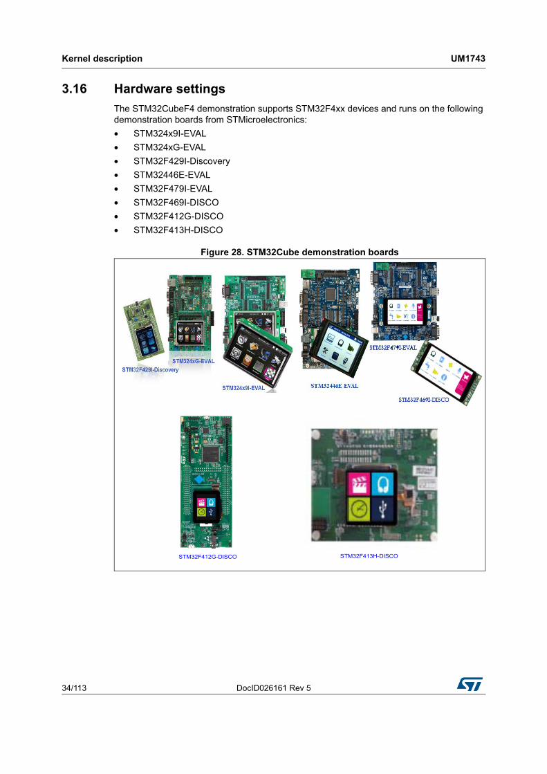
3.16 Hardware settings
The STM32CubeF4 demonstration supports STM32F4xx devices and runs on the following demonstration boards from STMicroelectronics:
• STM324x9I-EVAL
• STM324xG-EVAL
• STM32F429I-Discovery
• STM32446E-EVAL
• STM32F479I-EVAL
• STM32F469I-DISCO
• STM32F412G-DISCO
• STM32F413H-DISCO
Figure 28. STM32Cube demonstration boards
STM32F412G-DISCO STM32F413H-DISCO

DocID026161 Rev 5 35/113
UM1743 Kernel description
112
Table 7. Jumpers for different demonstration boards
Board Jumper Position description
STM324x9I-EVAL
JP16 Not fitted (used for USB device module)
JP4/JP5 <2-3> (used for Audio demonstration)
JP8 <2-3> (used for backup domain on battery)
STM324xG-EVAL
JP16 <2-3> (used for Audio demonstration)
JP19 <2-3> (used for backup domain on battery)
JP31 <2-3> (used for USB device module)
STM32F429I-DiscoveryJP3 ON (Power on MCU)
CN4 ON (Discovery mode)
STM324446E-EVALJP4 <2-3> (used for USB device module)
JP19 <1-2> (used for audio player module)
STM32F479I-EVAL
JP5/JP6 <2-3> (used for Audio demonstration)
JP7 <1-2> (used for VNC server demonstration)
JP2 Fitted (Power on MCU)
JP17/JP18 <2-3> (used for Audio recorder demonstration)
JP11 Fitted (disables the NOR Flash write protection)
STM32F469I-DISCO JP5 Fitted (Power on MCU)
STM32F412G-DISCO JP5 <1-2> VDD MCU: 3V3
STM32F413H-DISCO JP3 Fitted (Power on MCU)
How to create a new module UM1743
36/113 DocID026161 Rev 5
4 How to create a new module
A module is composed of two main parts:
• Graphical aspect: the main window frame and module's controls
• Functionalities: module functions and internal processes
4.1 Creating the graphical aspect
The graphical aspect consists of the main frame window in addition to the set of the visual elements and controls (buttons, check boxes, progress bars…) used to control and monitor the module's functionalities.
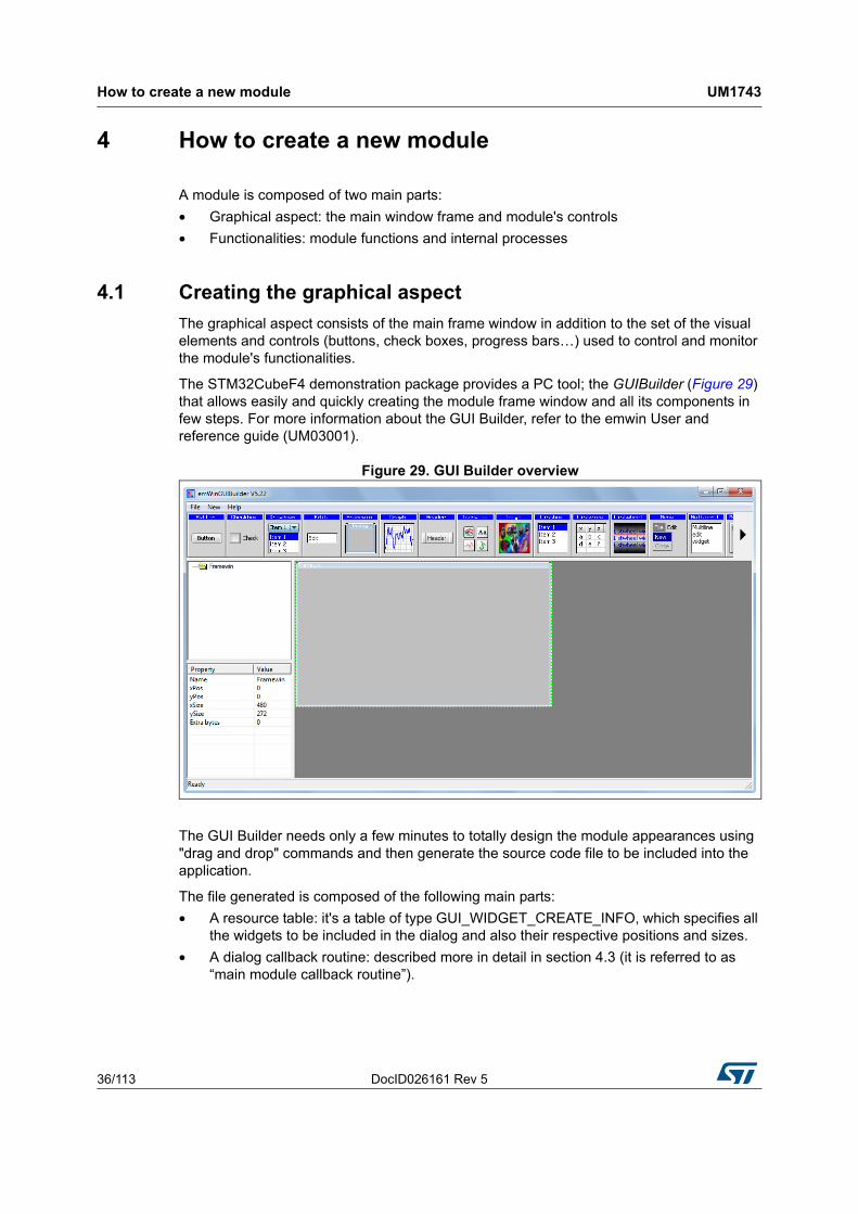
The STM32CubeF4 demonstration package provides a PC tool; the GUIBuilder (Figure 29) that allows easily and quickly creating the module frame window and all its components in few steps. For more information about the GUI Builder, refer to the emwin User and reference guide (UM03001).
Figure 29. GUI Builder overview
The GUI Builder needs only a few minutes to totally design the module appearances using "drag and drop" commands and then generate the source code file to be included into the application.
The file generated is composed of the following main parts:
• A resource table: it's a table of type GUI_WIDGET_CREATE_INFO, which specifies all the widgets to be included in the dialog and also their respective positions and sizes.
• A dialog callback routine: described more in detail in section 4.3 (it is referred to as “main module callback routine”).

DocID026161 Rev 5 37/113
UM1743 How to create a new module
112
4.2 Graphics customization
After the basic module graphical appearance is created, it is then possible to customize some graphical elements, such as the buttons, by replacing the standard aspect by the user defined image. To do this, a new element drawing callback should be created and used instead of the original one.
Below an example of a custom callback for the Play button:
On the code portion above, the _OnPaint_play routine contains just the new button drawing command.
Note that the new callback should be associated to the graphical element at the moment of its creation, as shown below:
Figure 30. Graphics customization
4.3 Module implementation
Once the graphical part of the module is finalized, the module functionalities and processes could be added then. It begins with the creation of the main module structure as defined in Section 3.7: Modules manager.

How to create a new module UM1743
38/113 DocID026161 Rev 5
Then, each module has its own Startup function which simply consists of the graphical module creation, initialization and link to the main callback:
In the example above cbDialog refers to the main module callback routine. Its general skeleton is structured like the following:
The list of windows messages presented in the code portion above (WM_INIT_DIALOG and WM_NOTIFY_PARENT) is not exhaustive, but represents the essential message IDs used:
• "WM_INIT_DIALOG: allows initializing the graphical elements with their respective initial values. It is also possible here to restore the backup parameters (if any) that will be used during the dialog procedure.
• "WM_NOTIFY_PARENT: describes the dialog procedure, for example: define the behavior of each button.
The full list of window messages can be found in the WM.h file.
4.4 Adding a module to the main desktop
Once the module appearance and functionality are defined and created, it still only to add the module to the main desktop view, this is done by adding it to the list (structure) of menu items: module_prop[ ], defined into k_module.h.
To do this, k_ModuleAdd() function should be called just after the module initialization into the main.c file.
Note that the maximum modules number in the demonstration package is limited to 15; this value can be changed by updating MAX_MODULES_NUM defined into k_module.c.

DocID026161 Rev 5 39/113
UM1743 How to create a new module
112
4.5 Module's direct open
If there is a need to launch the module directly from the file browser contextual menu, an additional method should be added in the module structure for the direct open feature. This callback is often named _ModuleName_DirectOpen.
Figure 31 is an example of how to open a file using the adequate module from the file browser.
Figure 31. Direct open from file browser
In the STM32CubeF4 demonstration, there are three modules linked to the file browser contextual menu:
• The video player(1), supporting the format:
– emf
• The image browser, supporting the formats:
– jpg
– bmp
• The audio player, supporting the format:
– wav.
Then, to link the module to the file browser open menu, the command k_ModuleOpenLink() is called after the module is added.
1. The video player is not supported by STM32446E-EVAL demonstration.

Demonstration customization and configuration UM1743
40/113 DocID026161 Rev 5
5 Demonstration customization and configuration
5.1 LCD configuration
The LCD is configured through the LCDConf.c file, see Figure 32. The main configuration items are listed below:
• Multiple layers:
– The number of layers to be used defined using GUI_NUM_LAYERS.
• Multiple buffering:
– If NUM_BUFFERS is set to a value "n" greater than 1, it means that "n" frame buffers will be used for drawing operation (see section 7.1 for impact of multiple buffering on performance).
• Virtual screens:
– If the display area is greater than the physical size of the LCD, NUM_VSCREENS should be set to a value greater than 1. Note that virtual screens and multi buffers are not allowed together.
• Frame buffers locations:
The physical location of frame buffer is defined through LCD_LAYERX_FRAME_BUFFER.
Figure 32. LCDConf location
5.2 Layers management
In the STM32CubeF4 demonstration package with the STM324x9I-EVAL, Discovery Kit, STM32F479I-EVAL and STM32F469I-DISCO, GUI_NUM_LAYERS is set to 2 (both layers are used):
• "Layer 0 is dedicated to background display
• "Layer 1 is used for the main desktop display
Dedicated layers usage will lighten the CPU load during the refresh tasks.

DocID026161 Rev 5 41/113
UM1743 Demonstration customization and configuration
112
5.3 Touchscreen calibration
When the demonstration is launched for the first time, the touchscreen needs to be calibrated. A full set of dedicated routines is included in the demonstration package and regrouped into k_calibration.c file (Figure 33).
Figure 33. k_calibration.c location
To do this, after the startup screen is displayed, the user has to follow the displayed calibration instructions by touching the screen at the indicated positions (Figure 34). This will allow getting the physical Touch screen values that will be used to calibrate the screen.

Demonstration customization and configuration UM1743
42/113 DocID026161 Rev 5
Figure 34. Calibration steps
Once this runtime calibration is done, the touch screen calibration parameters are saved to the RTC Backup data registers: RTC_BKP_DR0 and RTC_BKP_DR1, so the next time the application is restarted, these parameters are automatically restored and there is no need to re-calibrate the touchscreen.
Note: The touch screen calibration step is not needed for STM32F479I-EVAL and STM32F469-DISCO demonstrations.
5.4 BSP customization
5.4.1 SDRAM configuration
The SDRAM capacity is 1 Mbyte x 32 bits x 4 banks. The BSP SDRAM driver offers a set of functions to initialize, read/write in polling or DMA mode.

DocID026161 Rev 5 43/113
UM1743 Demonstration customization and configuration
112
Figure 35. SDRAM initialization
The SDRAM external memory must be initialized before the GUI initialization to allow its use as LCD layers frame buffer.
The SDRAM is used also as DCMI output for camera module. The camera output is stored in camera frame buffer address as 16 bpp (RGB565) and converted to 24 bpp in the Camera converted frame before its stocking in the selected storage unit.
5.4.2 Touch screen configuration
The touch screen is controlled by:
• the BSP TS driver, which uses the BSP IO driver for STM32429-EVAL, STM32446E-EVAL, STM32F479I-EVAL and STM32F469I-DISCO boards
• the TS3510 component for the STM32439-EVAL board
• the ft6x06 component for the STM32412G-DISCO and STM32413H-DISCO boards.
Table 8. LCD frame buffer locations
Layer Address
LCD Layer00xC0200000 0xC0000000 (for STM32F479I-EVAL and STM32F469-DISCO)
LCD Layer1 0xC0400000
Table 9. Camera frame buffer locations
Camera Address
Camera frame buffer 0xC0000000
Camera converted frame 0xC0025800

Demonstration customization and configuration UM1743
44/113 DocID026161 Rev 5
Figure 36. Touch screen initialization
The touch screen is initialized in 'k_BspInit' following the used screen resolution as shown in the code below.
DocID026161 Rev 5 45/113
UM1743 Performance
112
6 Performance
Note: This section is only available for STM329I-EVAL, STM32F479I-EVAL and STM32F469I-DISCO demonstrations.
6.1 Multi buffering features
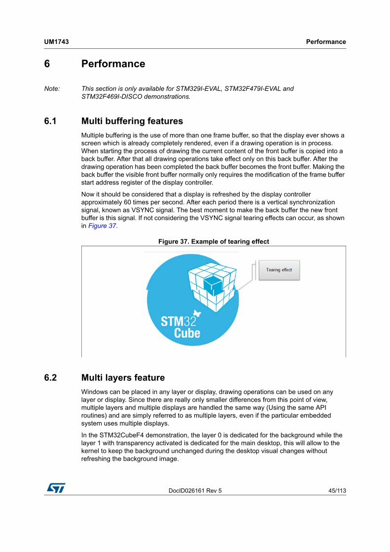
Multiple buffering is the use of more than one frame buffer, so that the display ever shows a screen which is already completely rendered, even if a drawing operation is in process. When starting the process of drawing the current content of the front buffer is copied into a back buffer. After that all drawing operations take effect only on this back buffer. After the drawing operation has been completed the back buffer becomes the front buffer. Making the back buffer the visible front buffer normally only requires the modification of the frame buffer start address register of the display controller.
Now it should be considered that a display is refreshed by the display controller approximately 60 times per second. After each period there is a vertical synchronization signal, known as VSYNC signal. The best moment to make the back buffer the new front buffer is this signal. If not considering the VSYNC signal tearing effects can occur, as shown in Figure 37.
Figure 37. Example of tearing effect
6.2 Multi layers feature
Windows can be placed in any layer or display, drawing operations can be used on any layer or display. Since there are really only smaller differences from this point of view, multiple layers and multiple displays are handled the same way (Using the same API routines) and are simply referred to as multiple layers, even if the particular embedded system uses multiple displays.
In the STM32CubeF4 demonstration, the layer 0 is dedicated for the background while the layer 1 with transparency activated is dedicated for the main desktop, this will allow to the kernel to keep the background unchanged during the desktop visual changes without refreshing the background image.

Performance UM1743
46/113 DocID026161 Rev 5
Figure 38. Independent layer management
6.3 Hardware acceleration
With the STM324x9I-EVAL and Discovery Kit demonstration, the hardware acceleration capabilities of the STM32F429/ STM32F439 cores are used. STemWin offers a set of customization callbacks to changes the default behavior based on the hardware capabilities, the optimized processes are implemented in the LCDConf.c file and implement the following features:
a) Color conversion
Internally STemWin works with logical colors (ABGR). To be able to translate these values into index values for the hardware and vice versa the color conversion routines automatically use the DMA2D for that operation if the layer work with direct color mode
This low level implementation makes sure that in each case where multiple colors or index values need to be converted the DMA2D is used.
b) Drawing of index based bitmaps
when drawing index based bitmaps STemWin first loads the palette of the bitmap into the DMA2Ds LUT instead of directly translating the palette into index values for the hardware. The drawing operation then is done by only one function call of the DMA2D.
c) Drawing of high color bitmaps
If the layer works in the same mode as the high color bitmap has its pixel data available, these bitmaps can be drawn by one function call of the DMA2D. The following function is used to set up such a function;:
LCD_SetDevFunc(LayerIndex, LCD_DEVFUNC_DRAWBMP_16BPP, pFunc);
d) Filling operations
Setting up the function for filling operations:
LCD_SetDevFunc(LayerIndex, LCD_DEVFUNC_FILLRECT, pFunc);
e) Copy operations
Setting up the functions for copy operations used by the function GUI_CopyRect():
LCD_SetDevFunc(LayerIndex, LCD_DEVFUNC_COPYRECT, pFunc);

DocID026161 Rev 5 47/113
UM1743 Performance
112
f) Copy buffers
Setting up the function for transferring the front- to the back buffer when using multiple buffers:
LCD_SetDevFunc(LayerIndex, LCD_DEVFUNC_COPYBUFFER, pFunc);
g) Fading operations
Setting up the function for mixing up a background and a foreground buffer used for fading memory devices:
GUI_SetFuncMixColorsBulk(pFunc);
h) General alpha blending
The following function replaces the function which is used internally for alpha blending operations during image drawing (PNG or true color bitmaps) or semitransparent memory devices:
GUI_SetFuncAlphaBlending(pFunc);
i) Drawing antialiased fonts
Setting up the function for mixing single foreground and background colors used when drawing transparent ant aliased text:
GUI_SetFuncMixColors(pFunc).

Footprint UM1743
48/113 DocID026161 Rev 5
7 Footprint
The purpose of the following sections is to provide the memory requirements for all the demonstration modules, including jpeg decoder and STemWin's main GUI components. The aim is to have an estimation of memory requirement in case of suppression or addition of a module or feature.
The footprint data are provided for the following environment:
• Tool chain: IAR 6.70.1
• Optimization: high size
• Board: STM32F429-EVAL.
7.1 Kernel footprint
Table 10 shows the code memory, data memory and the constant memory used for each kernel file.
7.2 Module footprint
Table 11 shows the code memory, data memory and the constant memory used for each kernel file.
Table 10. Kernel files footprint
File code [byte] data [byte] const [byte]
k_bsp 260 8 0
K_calibration 972 28 48
k_Log 100 8(1)
1. The memory is allocated dynamically in some structures of this file.
0
k_mem 266 0 0
k_menu 3496 900 412089
k_module 214 244 0
k_module_res 98 0 207692
k_rtc 196 32 195529
k_startup 316 4 300064
k_storage 954 2844 24
main 614 4 44
Table 11. Modules footprint
File code [byte] data [byte] const [byte]
Audio 6764 501(1) 33067
Benchmark 1320 36 32693

DocID026161 Rev 5 49/113
UM1743 Footprint
112
7.3 STemWin features resources
7.3.1 JPEG decoder
The JPEG decompression uses approximately 33 Kbytes of RAM for decompression independently of the image size and a size dependent amount of bytes. The RAM requirement can be calculated as follows:
Approximate RAM requirement = X-Size of image * 80 bytes + 33 Kbytes
The memory required for the decompression is allocated dynamically by the STemWin memory management system. After drawing the JPEG image the complete RAM will be released.
7.3.2 GUI components
The operation area of STemWin varies widely, depending primarily on the application and features used. In the following sections, memory requirements of various modules are listed, as well as the memory requirements of example applications.
Table 13 shows the memory requirements of the main components of STemWin. These values depend a lot on the compiler options, the compiler version and the used CPU. Note that the listed values are the requirements of the basic functions of each module.
Camera 2467 213(1) 62629
File Browser 3062 516 69083
Game 4188 1916 33432
Image Browser 5308 1956(1) 32862
System 2486 89 33506
USB Device 540 29 195529
Video Player 6476 989(1) 32646
1. The memory is allocated dynamically in some structures of this file.
Table 11. Modules footprint (continued)
File code [byte] data [byte] const [byte]
Table 12. RAM requirements for some JPEG resolutions
Resolutiont RAM usage [kbyte] RAM usage, size dependent [kbyte]
160x120 45.5 12.5
320x340 58.0 25.0
480x272 70.5 37.5
640x480 83.0 50.0

Footprint UM1743
50/113 DocID026161 Rev 5
Table 13. MemoSTemWin components memory requirements
Component ROM RAM Description
Windows Manager 6.2 Kbytes 2.5 Kbytes Additional memory requirements of basic application when using the Windows Manager
Memory Devices 4.7 Kbytes 7 Kbytes Additional memory requirements of basic application when using memory devices
Antialiasing 4.5 Kbytes 2 * LCD_XSIZEAdditional memory requirements for the antialiasing software item
Driver 2-8 Kbytes 20 bytes
The memory requirements of the driver depend on the configured driver and whether a data cache is used or not.
With a data cache, the driver requires more RAM
Multilayer 2-8 Kbytes -
If working with a multi layer or a multi display configuration, additional memory is required for each additional layer, because each requires its own driver
Core 5.2 Kbytes 80 bytesMemory requirements of a typical application without using additional software items
JPEG 12 Kbytes 36 Kbytes Basic routines for drawing JPEG files
GIF 3.3 Kbytes 17 Kbytes Basic routines for drawing GIF files
Sprites 4.7 Kbytes 16 bytes Routines for drawing sprites and cursors
Font 1-4 Kbytes - Depends on the font size to be used
Table 14. Widget memory requirements
Component ROM RAM Description
BUTTON 1.0 Kbytes 40 bytes (1)
CHECKBOX 1.0 Kbytes 52 bytes (1)
DROPDOWN 1.8 Kbytes 52 bytes (1)
EDIT 2.2 Kbytes 28 bytes (1)
FRAMEWIN 2.2 Kbytes 12 bytes (1)
GRAPH 2.9 Kbytes 48 bytes (1)
GRAPH_DATA_XY 0.7 Kbytes - (1)
GRAPH_DATA_XY 0.6 Kbytes - (1)
HEADER 2.8 Kbytes 32 bytes (1)
LISTBOX 3.7 Kbytes 56 bytes (1)
LISTVIEW 3.6 Kbytes 44 bytes (1)
MENU 5.7 Kbytes 52 bytes (1)
MULTIEDIT 7.1 Kbytes 16 bytes (1)

DocID026161 Rev 5 51/113
UM1743 Footprint
112
MULTIPAGE 3.9 Kbytes 32 bytes (1)
PROGBAR 1.3 Kbytes 20 bytes (1)
RADIOBUTTON 1.4 Kbytes 32 bytes (1)
SCROLLBAR 2.0 Kbytes 14 bytes (1)
SLIDER 1.3 Kbytes 16 bytes (1)
TEXT 1.0 Kbytes 16 bytes (1)
CALENDAR 0.6 Kbytes 32 bytes (1)
1. The listed memory requirements of the widgets contain the basic routines required for creating and drawing the widget. Depending on the specific widget there are several additional functions available which are not listed in the table
Table 14. Widget memory requirements (continued)
Component ROM RAM Description

Demonstration functional description (STM324x9I-EVAL, STM324xG-EVAL, STM32F429I-Discov-
52/113 DocID026161 Rev 5
8 Demonstration functional description (STM324x9I-EVAL, STM324xG-EVAL, STM32F429I-Discovery and STM32446E-EVAL)
8.1 Kernel
The main desktop is built around two main graphical components:
• The status bar: indicates the storage units' connection status, current time and date and a system utilities button to allow getting system information like (running task, CPU usage, and kernel log).
• The icon view widget: contains the icons associated to added modules. User can launch a module by a simple click on the module icon (see Figure 39).
Figure 39. CPU usage display
The system utilities are accessible during the STM32CubeF4 demonstration running time, using the system button (ST Logo) in top left of the main desktop. The system utilities button offers the following services:
• CPU usage history
• Kernel log messages
• Current running processes viewer

DocID026161 Rev 5 53/113
UM1743Demonstration functional description (STM324x9I-EVAL, STM324xG-EVAL, STM32F429I-
112
8.1.1 CPU usage
The CPU usage utility provides a graphical representation of the CPU usage evolution (Figure 40) during the demonstration run time starting for the first time it was launched. Note that once launched the CPU usage utilities keep running in background and can be restored in any time.
Figure 40. CPU usage
8.1.2 Kernel log
The kernel log utility gathers all the kernel and module messages and saves them into a dedicated internal buffer. The Log messages can be visualized at any time during the demonstration run time, as shown in Figure 41.
Figure 41. Example of Log messages

Demonstration functional description (STM324x9I-EVAL, STM324xG-EVAL, STM32F429I-Discov-
54/113 DocID026161 Rev 5
8.1.3 Process viewer
The process viewer (Figure 42) allows users to check and to display the status of the currently running tasks (FreeRTOS) at any time during the demonstration run time. It shows the following information:
1. Current running tasks names.
2. Current running tasks priorities
3. Running tasks states (FreeRTOS statics information).
Figure 42. Process viewer
8.2 Modules
8.2.1 System
Overview
The system module provides three control tabs: system information, general settings and clock settings to set the global demonstration settings. The system module retrieves demonstration information from internal kernel settings data structures and acts on the several kernel services to changes settings.
Functional description
The system module provides three graphical views:
a) Demonstration global Information (Figure 43)
This first page shows the main demonstration information such as: Used board, STM32 core part number, and current CPU clock and demonstration revision.
b) General settings (Figure 44)
The general settings tab permits to change the global demonstration configuration. Note that the new settings are not applied immediately; new settings take effect after restarting the demonstration.

DocID026161 Rev 5 55/113
UM1743Demonstration functional description (STM324x9I-EVAL, STM324xG-EVAL, STM32F429I-
112
Figure 43. Demonstration global information
Figure 44. Demonstration general settings

Demonstration functional description (STM324x9I-EVAL, STM324xG-EVAL, STM32F429I-Discov-
56/113 DocID026161 Rev 5
Table 15 shows the different settings that can be changed.
c) Clock settings
The clock setting tab (Figure 45) allows to adjust the demonstration time and date by changing the RTC configuration of the kernel.
Figure 45. Clock setting
Table 15. Available settings
Configuration item Description
Enable sprites
Checking this box allows the sprites to move on the background desktop
Enable background mode Not used (reserved for future use)
Run CPU at 180 MHz
Allow to run the demonstration at maximum speed. Note that the device USB clock is not at compliant clock with mode. To use the USB device mass storage module, it is recommended to use the default 168 MHz CPU clock
Disable Flex skin
Unchecking this box, classical GUI skin is used.
DocID026161 Rev 5 57/113
UM1743Demonstration functional description (STM324x9I-EVAL, STM324xG-EVAL, STM32F429I-
112
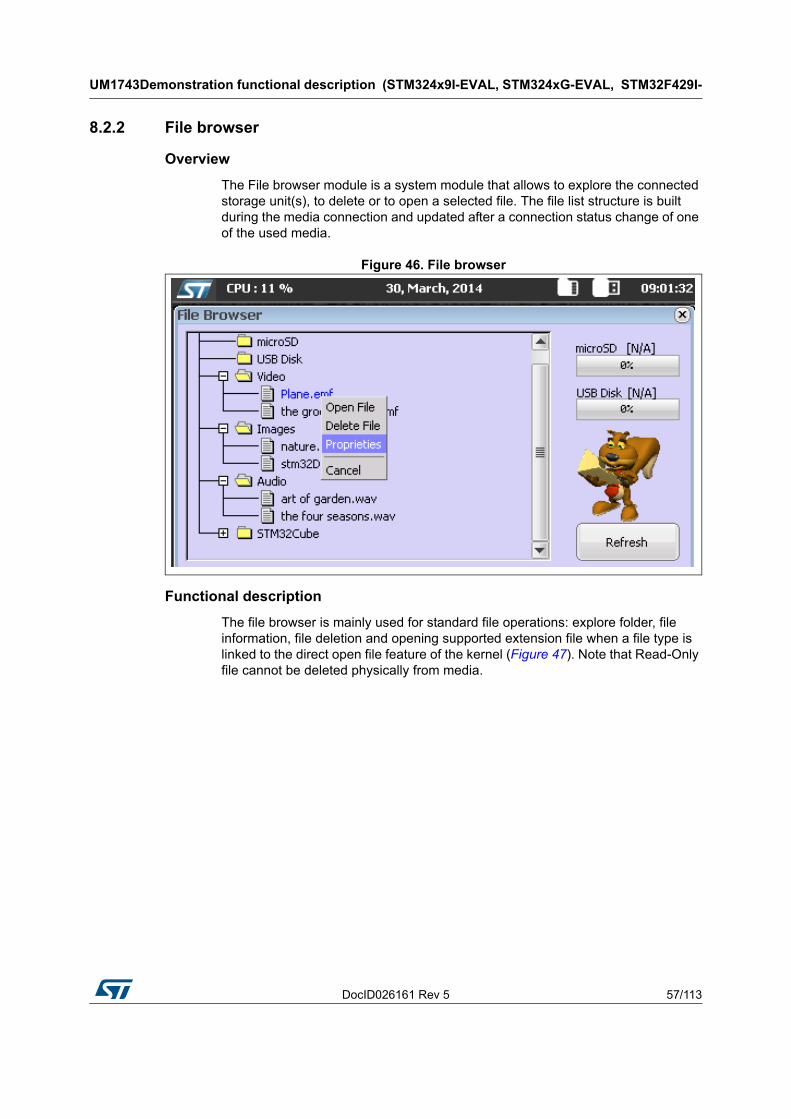
8.2.2 File browser
Overview
The File browser module is a system module that allows to explore the connected storage unit(s), to delete or to open a selected file. The file list structure is built during the media connection and updated after a connection status change of one of the used media.
Figure 46. File browser
Functional description
The file browser is mainly used for standard file operations: explore folder, file information, file deletion and opening supported extension file when a file type is linked to the direct open file feature of the kernel (Figure 47). Note that Read-Only file cannot be deleted physically from media.

Demonstration functional description (STM324x9I-EVAL, STM324xG-EVAL, STM32F429I-Discov-
58/113 DocID026161 Rev 5
Figure 47. File browser module architecture
To open the contextual file menu, user has to select a file (selecting a folder has no effect).
The following actions are accessible through the contextual menu:
a) Open file: if a file extension is linked to the direct open file feature of the kernel, the associated application with this extension is launched and the file is opened automatically (Figure 48).
b) Delete file: selecting a file for deletion will display a confirmation message box to confirm the deletion operation. Note that Read-Only file cannot be deleted physically from media.
c) Proprieties: the File browser can be used to check file proprieties such as current location, size, and creation date,as indicated in Figure 49.
Note: The File browser can explore up to four levels, the maximum explorer level is defined in the kernel files (k_storage.h).
Figure 48. File opening from browser

DocID026161 Rev 5 59/113
UM1743Demonstration functional description (STM324x9I-EVAL, STM324xG-EVAL, STM32F429I-
112
Figure 49. File properties display
8.2.3 Game
The game coming in the STM32CubeF4 demonstration is based on the Reversi game. It is a strategy board game for two players, played on an 8×8 board. The goal of the game is to have the majority of disks turned to display your color when the last playable empty square is filled.
Figure 50. Reversi game
In this STM32CubeF4 demonstration STM32 MCU is one of the two players. The GUI will ask the user to start a new game when the ongoing one is over.

Demonstration functional description (STM324x9I-EVAL, STM324xG-EVAL, STM32F429I-Discov-
60/113 DocID026161 Rev 5
8.2.4 Benchmark
Overview
The Benchmark module is a system module that allows measure the graphical performance by measuring the time needed to draw several colored rectangles in random position with random size during a specific period. The result is given in pixel per second.
Functional description
The benchmark starts immediately once the start speed benchmark button is pressed. After few seconds the result is displayed in red below the CPU Usage graphical window and result is logged in the right list box with date and time stamp (Figure 51).
Figure 51. Benchmarking
8.2.5 Audio
Overview
The audio player module provides a complete audio solution based on the STM32F4xx and delivers a high-quality music experience. It supports playing music in WAV format but may be extended to support other compressed formats such as MP3 and WMA audio formats.
Architecture
Figure 52 shows the different audio player parts and their connections and interactions with the external components.

DocID026161 Rev 5 61/113
UM1743Demonstration functional description (STM324x9I-EVAL, STM324xG-EVAL, STM32F429I-
112
Figure 52. Audio player module architecture
Data structure used
Table 16 contains the different data structure used in audio player module and a brief description of each of them.
Table 16. Data structure for audio
Structure Description
WAV_InfoTypedef Contains the wave file information extracted from wave file header
AUDIOPLAYER_ProcessTypdefContains the audio player state, the speaker state, the volume value and the pointer to the audio buffer.
AUDIOPLAYER_StateTypdef
Contains the different audio player state:
– AUDIOPLAYER_STOP
– AUDIOPLAYER_START
– AUDIOPLAYER_PLAY
– AUDIOPLAYER_PAUSE
– AUDIOPLAYER_EOF
– AUDIOPLAYER_ERROR

Demonstration functional description (STM324x9I-EVAL, STM324xG-EVAL, STM32F429I-Discov-
62/113 DocID026161 Rev 5
Functional description
The audio player initialization is done in startup step. In this step all the audio player states, the speaker and the volume value are initialized and only when the play button in the audio player interface is pressed to start the process.
There are two ways to start audio player module:
• From main desktop menu as shown in Figure 53
• Through the file browser contextual menu: direct open feature.
Figure 53. Audio player module startup
When the audio player is started, the following actions are executed:
• The graphical components are initialized:
– The audio frame
– The control buttons
– The list box field
An additional memory is allocated to keep the audio list (pWavList) and the audio file information (pFileInfo).
AUDIOPLAYER_ErrorTypdef
Contains the different possible error.
– AUDIOPLAYER_ERROR_NONE
– AUDIOPLAYER_ERROR_IO
– AUDIOPLAYER_ERROR_HW
– AUDIOPLAYER_ERROR_MEM
– AUDIOPLAYER_ERROR_FORMAT_NOTSUPPORTED
BUFFER_StateTypeDef
Contains the different Buffer state
– BUFFER_OFFSET_NONE
– BUFFER_OFFSET_HALF
– BUFFER_OFFSET_FULL.
Table 16. Data structure for audio (continued)
Structure Description

DocID026161 Rev 5 63/113
UM1743Demonstration functional description (STM324x9I-EVAL, STM324xG-EVAL, STM32F429I-
112
Table 17. Audio module controls
Button Preview Description
Play button
Changes the audio player state to “AUDIOPLAYER_PLAY”
Reads the wave file from storage unit
Sets the frequency
Starts or resumes the audio task
Starts playing audio stream from a data buffer using “BSP_AUDIO_OUT_Play” function in BSP audio driver.
Replaces play button by pause button
Pause button
Suspends the audio task
Pauses the audio file stream
Replaces pause button by play button
Stop button
Close the wave file from storage unit
Suspends the audio task
Stops audio playing
Changes the audio player state to “AUDIOPLAYER_STOP”
Previous button
Point to the previous wave file
Stops audio playing
Starts playing the previous wave file if play button is pressed
Next button
Point to the next wave file
Stops audio playing
Starts playing the next wave file if play button is pressed
Add file to playlist
Open file browser window and choose wave file to be added to playlist
Add foldersOpen file browser window and choose entire folder to be added to playlist
Repeat buttons
At the end of file:
- If repeat all is selected next wave file is selected and played
- If repeat once is selected the played wave file is repeated
- If repeat off is selected the audio player stop
Speaker buttonSets the volume at mute (first press)
Sets the volume at value displayed in volume slider (second press
Volume slider Sets the volume value
Progress slider Sets the desired position in the wave file
Close button Close audio player module

Demonstration functional description (STM324x9I-EVAL, STM324xG-EVAL, STM32F429I-Discov-
64/113 DocID026161 Rev 5
8.2.6 Video
Overview
The video player module provides a video solution based on the STM32F4xx and STemWin movie API. It supports playing movie in emf format.
Architecture
Figure 54 shows the different video player modules and their connections and interactions with the external components.
Figure 54. Video player module architecture
Functional description
There are two ways to start Video player module:
• Either by touching the video player icon: Figure 55
• Or by using the file browser contextual menu: direct open feature.

DocID026161 Rev 5 65/113
UM1743Demonstration functional description (STM324x9I-EVAL, STM324xG-EVAL, STM32F429I-
112
When the video player is started, the following actions are executed:
• The graphical components are initialized:
– The video frame
– The control buttons
– The list box field
• Memory is allocated to save the video list (pVideoList) and the file information (pFileInfo).
Figure 55. Video player module startup
Table 18 summarizes the different actions behind each control button.
Table 18. Video module controls
Button Preview Description
Play button
Checks if the video size is not supported
Supported video size: 0 < xSize < 1024 and 0 < ySize < 768
Changes the video player state to “VIDEO_PLAY”
Reads the video file from storage unit
Replaces play button by pause button
Pause button
Pauses the video file stream
Changes the video player state to “VIDEO_PAUSE”
Replaces pause button by play button
Stop button
Closes the video file from storage unit
Stops video playing
Changes the video player state to “VIDEO_IDLE”
Previous button
Points to the previous video file
Stops video playing
Changes the video player state to “VIDEO_IDLE”

Demonstration functional description (STM324x9I-EVAL, STM324xG-EVAL, STM32F429I-Discov-
66/113 DocID026161 Rev 5
Video file creation (emf)
To be able to play movies with the STemWin API functions it is required to create files of the STemWin specific EmWin movie file format. There are two steps to generate an emf file:
a) Convert files of any MPEG file format into a folder of single JPEG files for each frame (Figure 56). The free FFmpeg available at ffmpeg website can be used.
Next button
Points to the next video file
Stops video playing
Starts playing the next video file if play button is pressed
Add file to playlistOpens file browser window and choose emf file from available storage unit to be added to playlist
Add folderOpens file browser window and choose entire folder from available storage unit to be added to playlist
Repeat buttons
At the end of file:
- If repeat all is selected next video file is selected and played
- If repeat once is selected the played video file is repeated
- If repeat off is selected the video player stops
Progress slider Sets the desired position in the emf file
Full screen button Scales the image to be showed on full screen mode
Close button Closes video player module
Table 18. Video module controls (continued)
Button Preview Description

DocID026161 Rev 5 67/113
UM1743Demonstration functional description (STM324x9I-EVAL, STM324xG-EVAL, STM32F429I-
112
Figure 56. EMF generation environment
b) Create an emf file from JPEG file using JPEG2Movie tool available in STemWin package (see Figure 57).
Figure 57. JPEG2Movie overview

Demonstration functional description (STM324x9I-EVAL, STM324xG-EVAL, STM32F429I-Discov-
68/113 DocID026161 Rev 5
The above steps could be done once using a predefined batch (included in the STemWin package) as shown in Figure 58.
Figure 58. EMF file generation
For more information about how to use the emf generation batches, refer to the STemWin User and Reference Guide (UM3001).
Table 19. Batch files description
File Explanation
Prep.batSets some defaults to be used.
Needs to be adapted as explained in Prep.bat.
MakeMovie.batMain conversion file.
Not to be adapted normally.
<X_SIZE>x<Y_SIZE>.batSome helper files for different resolutions.
Detailed explanation in <X_SIZE>x<Y_SIZE>.bat

DocID026161 Rev 5 69/113
UM1743Demonstration functional description (STM324x9I-EVAL, STM324xG-EVAL, STM32F429I-
112
Prep.bat
The Prep.bat is required to prepare the environment for the actual process. Calling it directly will not have any effect. It is called by the MakeMovie.bat. To be able to use the batch files it is required to adapt this file at first. This file sets variables used by the file MakeMovie.bat, they are listed in Table 20.
.
MakeMovie.bat
This is the main batch file used for the conversion process. Normally it is not required to be change this file, but it is required to adapt Prep.bat first. It could be called with the parameters listed in Table 21:
Table 20. Variables description
Variable Description
%OUTPUT%Destination folder for the JPEG files.
Will be cleared automatically when starting the conversion with MakeMovie.bat.
%FFMPEG%Access variable for the FFmpeg tool.
Should contain the complete path required to call FFmpeg.exe.
%JPEG2MOVIE%Access variable for the JPEG2MOVIE tool.
Should contain the complete path required to call JPEG2Movie.exe.
%DEFAULT_SIZE%Default movie resolution to be used.
Can be ignored if one of the <X-SIZE>x<Y-SIZE>.bat files are used.
%DEFAULT_QUALITY%
Default quality to be used by FFmpeg.exe for creating the JPEG files.
The lower the number the better the quality. Value 1 indicates that a very good quality should be achieved, value 31 indicates the worst quality.
For more details please refer to the FFmpeg documentation.
%DEFAULT_FRAMERATE%
Frame rate in frames/second to be used by FFmpeg.
It defines the number of JPEG files to be generated by FFmpeg.exe for each second of the movie.
For more details please refer to the FFmpeg documentation.
Table 21. Parameters description
Parameter Description
%1 Movie file to be converted
%2 (optional)Size to be used.
If not given %DEFAULT_SIZE% of Prep.bat is used.
%3 (optional)Quality to be used.
If not given %DEFAULT_QUALITY% of Prep.bat is used.
%4 (optional)Frame rate to be used.
If not given %DEFAULT_FRAMERATE% of Prep.bat is used.

Demonstration functional description (STM324x9I-EVAL, STM324xG-EVAL, STM32F429I-Discov-
70/113 DocID026161 Rev 5
Since the FFmpeg output can differ strongly from the output of previous actions, the MakeMovie.bat deletes all output files in the first place. The output folder is defined by in the environmental variable %OUTPUT% in Prep.bat. After that it uses FFmpeg.exe to create the required JPEG files for each frame. Afterwards it calls JPEG2Movie to create a single EMF file which can be used by STemWin directly. After the conversion operation the result can be found in the conversion folder under FFmpeg.emf. It also creates a copy of that file into the source file folder. It will have the same name as the source file with a size-postfix and .emf extension.
<X_SIZE>x<Y_SIZE>.bat
These files are small but useful helpers if several movie resolutions are required. The filenames of the batch files itself are used as parameter '-s' for FFmpeg.exe. You can simply drag-and-drop the file to be converted to one of these helper files. After that an .emf file with the corresponding size-postfix can be found in the source file folder.
8.2.7 USB mass storage device (USBD)
Overview
The USB device module includes mass storage device application using the MicroSD memory. It uses the USB OTG FS peripheral as the USB OTG HS is used for the USB disk Flash storage unit.
Architecture
Figure 59 shows the different USBD module components and their connections and interactions with the external components.
Figure 59. USBD module architecture

DocID026161 Rev 5 71/113
UM1743Demonstration functional description (STM324x9I-EVAL, STM324xG-EVAL, STM32F429I-
112
Data structure used
Functional description
Run USB Device demonstration by clicking USB device icon in the main desktop, as in Figure 60.
Figure 60. USBD module startup
Table 22. Data structure for USBD module
Structure Description
USBDSettingsTypeDef sd_mounted: connection status
Table 23. USBD module controls
Button Preview Description
Connect USB
Changes the USB logo as follows:
Changes the USBD status as CONNECTED
Disconnect USB
Changes the USB logo as follows:
Changes the USBD status as DISCONNECTED

Demonstration functional description (STM324x9I-EVAL, STM324xG-EVAL, STM32F429I-Discov-
72/113 DocID026161 Rev 5
8.2.8 Camera
Overview
The camera application allows to directly and permanently display on the LCD the image captured using the camera module. It is also possible to take a snapshot and save it to a customizable location in the storage unit.
In addition to brightness and contrast which are adjustable, several effects can be applied to the output image: black and white, negative, antique...etc. Note that all these effects can be applied in runtime.
Architecture
Figure 61 shows the different camera module parts and their respective connections and interactions with the external components.
Insert
microSD cardNA
Changes the microSD logo as follows:
Remove
microSD cardNA
Changes the microSD logo as follows:
Close Closes USBD module
Table 23. USBD module controls (continued)
Button Preview Description

DocID026161 Rev 5 73/113
UM1743Demonstration functional description (STM324x9I-EVAL, STM324xG-EVAL, STM32F429I-
112
Figure 61. Camera module architecture
Functional description
To start the camera module click on the Camera icon, as indicated in Figure 62.
Figure 62. Camera module startup
When the camera module is started, the following actions are executed:
• The graphical components are initialized.
• Memory is allocated to save the capture folder location (pFileInfo).
• The saved parameters (brightness and contrast) are restored from the RTC backup register.
Table 24 summarizes the different actions behind each control button.

Demonstration functional description (STM324x9I-EVAL, STM324xG-EVAL, STM32F429I-Discov-
74/113 DocID026161 Rev 5
8.2.9 Image viewer
Overview
The Image viewer module allows displaying bmp and jpg pictures. It is possible to load the full images list from a folder or to add the images manually to the playlist. Once the playlist is created, navigation between pictures can be done either via Next and previous buttons or by enabling the slide show mode. The slide show timer can be changed on the fly (there is no need to restart the module).
Architecture
Figure 63 shows the different image viewer parts and their respective connections and interactions with the external components.
Table 24. Camera module controls
Button Preview Description
Settings Creates and shows the settings dialog
Capture
Checks the camera state
Displays a popup message ("Saving image...")
Saves the current image to the specified file (default path is the root)
Deletes the popup message
Close
Frees allocated memory during the initialization
Stops the camera module
Ends the module dialog
Effects Applies the selected effect on the fly via the BSP camera driver commands

DocID026161 Rev 5 75/113
UM1743Demonstration functional description (STM324x9I-EVAL, STM324xG-EVAL, STM32F429I-
112
Figure 63. Image viewer architecture
Functional description
There are two ways to start Image viewer module:
• Either by touching the Image viewer icon (Figure 64);
• Or by using the file browser contextual menu: direct open feature.
When the image viewer is started, the following actions are executed:
• The graphical components are initialized:
– The image frame
– The control buttons
– The list box field
• Memory is allocated to save the image list (pImageList) and the file information (pFileInfo).
• The saved parameters are restored from the RTC backup register.

Demonstration functional description (STM324x9I-EVAL, STM324xG-EVAL, STM32F429I-Discov-
76/113 DocID026161 Rev 5
Figure 64. Image viewer startup
Table 25 summarizes the different actions behind each control button.
Table 25. Image viewer module controls
Button Preview Description
CloseFrees allocated memory
Ends the module dialog
Previous
Closes the current image
Opens the previous image
Refreshes the image frame
Updates the selection in the playlist
Start slideshow
Closes the current image
Opens the next image
Refreshes the image frame
Creates the slideshow timer
Next
Closes the current image
Opens the next image
Refreshes the image frame
Updates the selection in the playlist
Settings Creates and shows the settings dialog
Add folderOpens the directory chooser to allow selection of an entire folder and then adds all the images included in this folder to the playlist
Add fileOpens the file chooser to allow selection of an image which will be added to the playlist.

DocID026161 Rev 5 77/113
UM1743 Demonstration functional description (STM32F479I-EVAL and STM32F469I-DISCO)
112
9 Demonstration functional description (STM32F479I-EVAL and STM32F469I-DISCO)
9.1 Modules
9.1.1 Audio
Overview
The audio player module provides a complete audio solution based on the STM32F4xx and delivers a high-quality music experience. It supports playing music in WAV format but may be extended to support other compressed formats such as MP3 and WMA audio formats.
Features
• Audio Format: WAV format without compression with 8k to 96 k sampling
• Embeds an equalizer and loudness control
• Performance: MCU Load < 5%
• Audio files stored in USB Disk flash (USB High Speed)
• Support background mode feature
• Only 8 Kbytes of RAM required for Audio processing
MP3 Format is not supported but can be easily added (separate demonstration)
Architecture and performance
Figure 65 shows the different audio player parts and their connections and interactions with the external components, while Figure 66 details the mechanisms.
Figure 65. Audio player module architecture

Demonstration functional description (STM32F479I-EVAL and STM32F469I-DISCO) UM1743
78/113 DocID026161 Rev 5
Figure 66. Audio player module performance mechanisms
Functional description
The audio player initialization is carried out in the startup step: all the audio player states, the speaker and the volume value are initialized (when the Play button in the audio player interface is pressed to start the process):
• start audio player module from main desktop menu, as shown in Figure 67;
• add audio file to play list (Figure 68);
• click on the Equalizer icon to open the equalizer and loudness frame (Figure 69);
• activate background (Figure 70).
Figure 67. Start audio player

DocID026161 Rev 5 79/113
UM1743 Demonstration functional description (STM32F479I-EVAL and STM32F469I-DISCO)
112
Figure 68. Adding audio files to the playlist
Figure 69. Equalizer and loudness frame
Figure 70. Background mode

Demonstration functional description (STM32F479I-EVAL and STM32F469I-DISCO) UM1743
80/113 DocID026161 Rev 5
Figure 71. Hardware connectivity
Table 26. Image viewer module controls
Button Preview Description
Play
Changes the audio player state to “AUDIOPLAYER_PLAY”
Reads the wave file from storage unit
Sets the frequency
Starts or resumes the audio task
Starts playing audio stream from a data buffer using “BSP_AUDIO_OUT_Play” function in BSP audio driver.
Replaces play button by pause button
Pause
Suspends the audio task
Pauses the audio file stream
Replaces pause button by play button
Stop
Close the wave file from storage unit
Suspends the audio task
Stops audio playing
Changes the audio player state to “AUDIOPLAYER_STOP”
Previous
Point to the previous wave file
Stops audio playing
Starts playing the previous wave file if play button is pressed
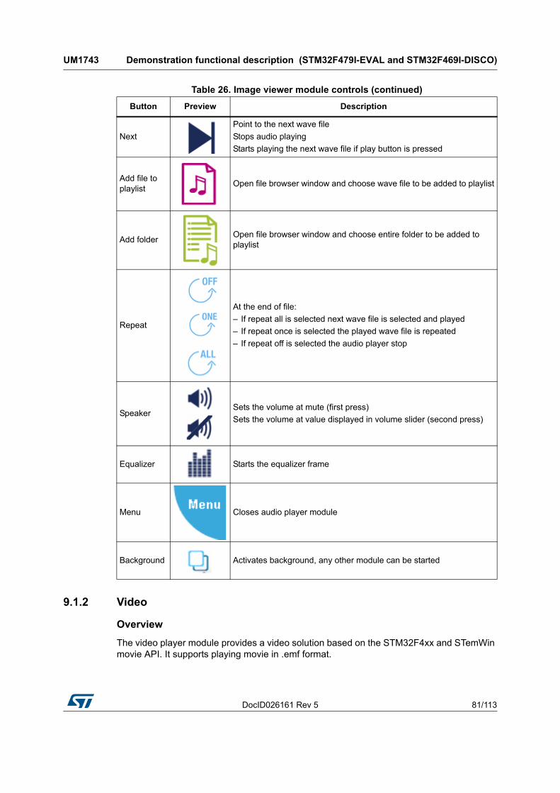
DocID026161 Rev 5 81/113
UM1743 Demonstration functional description (STM32F479I-EVAL and STM32F469I-DISCO)
112
9.1.2 Video
Overview
The video player module provides a video solution based on the STM32F4xx and STemWin movie API. It supports playing movie in .emf format.
Next
Point to the next wave file
Stops audio playing
Starts playing the next wave file if play button is pressed
Add file to playlist
Open file browser window and choose wave file to be added to playlist
Add folderOpen file browser window and choose entire folder to be added to playlist
Repeat
At the end of file:
– If repeat all is selected next wave file is selected and played
– If repeat once is selected the played wave file is repeated
– If repeat off is selected the audio player stop
SpeakerSets the volume at mute (first press)
Sets the volume at value displayed in volume slider (second press)
Equalizer Starts the equalizer frame
Menu Closes audio player module
Background Activates background, any other module can be started
Table 26. Image viewer module controls (continued)
Button Preview Description

Demonstration functional description (STM32F479I-EVAL and STM32F469I-DISCO) UM1743
82/113 DocID026161 Rev 5
Features
• Video Format: STemWin emf Video Format (Motion-Jpeg)
• Performance: MCU Load < 70% / Rate: up to 15 fps
• Video files stored in USB Disk flash (USB High Speed)
• Use of the 2 LCD layers (Playback control/ Video display)
• 64 Kbytes of RAM required for JPEG decoding
Architecture and performance
Figure 72 shows the different audio player parts and their connections and interactions with the external components, while Figure 73 details the mechanisms.
Figure 72. Video player module architecture

DocID026161 Rev 5 83/113
UM1743 Demonstration functional description (STM32F479I-EVAL and STM32F469I-DISCO)
112
Figure 73. Video player module performance
Functional description
• Start Video player module by touching the video player icon
• When the video player is started, the icon shown in Figure 74 is displayed
• Add video file to playlist by touching “Add to playlist” icon, as in Figure 75
• Play video file by touching “Play video” icon
• If there is no video file selected the popup shown in Figure 76 appears
• Else, the video file starts playing (Figure 77)
• Touch the screen to hide control keys, hardware information and video file information (see Figure 78).
Figure 74. Start video player
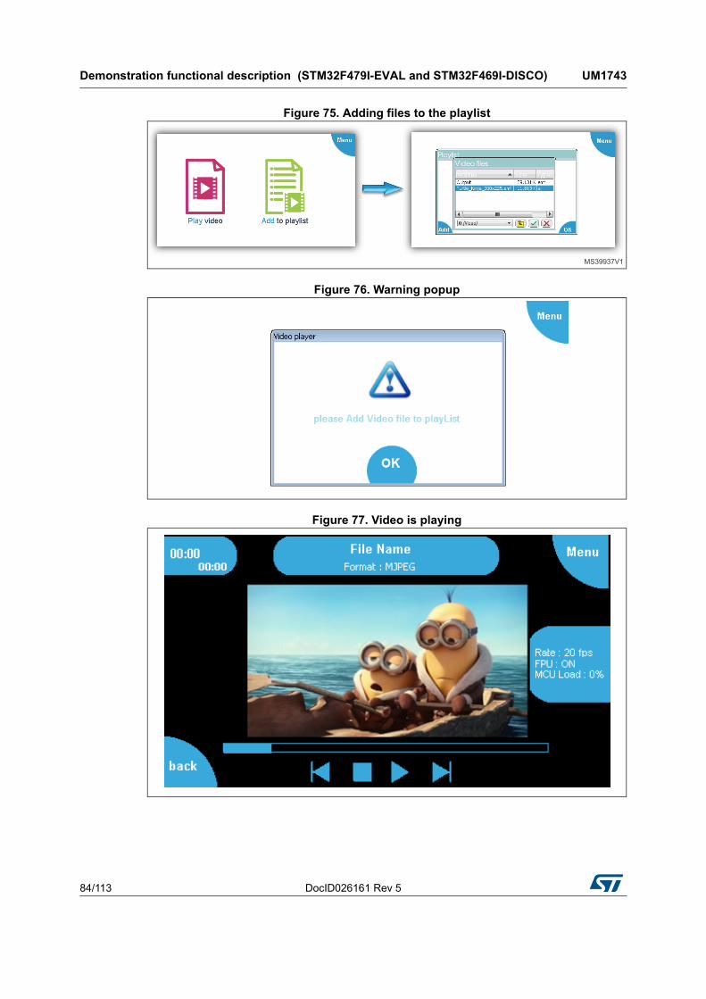
Demonstration functional description (STM32F479I-EVAL and STM32F469I-DISCO) UM1743
84/113 DocID026161 Rev 5
Figure 75. Adding files to the playlist
Figure 76. Warning popup
Figure 77. Video is playing

DocID026161 Rev 5 85/113
UM1743 Demonstration functional description (STM32F479I-EVAL and STM32F469I-DISCO)
112
Figure 78. Hiding control keys and other information
Table 27. Video module controls
Button Preview Description
Play
Checks if the video size is not supported
Supported video size: 0 < xSize < 1024 and 0 < ySize < 768
Changes the video player state to “VIDEO_PLAY”
Reads the video file from storage unit Replaces play button by pause button
Pause
Pauses the video file stream
Changes the video player state to “VIDEO_PAUSE”
Replaces pause button by play button
Next
Points to the next video file
Stops video playing
Starts playing the next video file if play button is pressed
Previous
Point to the previous video file
Stops video playing
Changes the video player state to “VIDEO_IDLE”
Stop
Closes the video file from storage unit
Stops video playing
Changes the video player state to “VIDEO_IDLE”
Back Back to previous video player frame to add new video file
Menu Closes video player module

Demonstration functional description (STM32F479I-EVAL and STM32F469I-DISCO) UM1743
86/113 DocID026161 Rev 5
Video file creation (emf)
To be able to play movies with the STemWin API functions it is required to create files of the STemWin specific EmWin movie file format. There are two steps to generate an emf file:
1. Convert files of any MPEG file format into a folder of single JPEG files for each frame (see Figure 79). The free FFmpeg available at ffmpeg website can be used.
2. Create an emf file from JPEG file using JPEG2Movie tool available in STemWin package (Figure 80).
Figure 79. EMF generation format
Figure 80. JPEG2Movie overview
These steps can be done once using a predefined batch (included in the STemWin package) as shown in Figure 81.
For more information about how to use the emf generation batches, refer to the STemWin User and Reference Guide (UM3001).

DocID026161 Rev 5 87/113
UM1743 Demonstration functional description (STM32F479I-EVAL and STM32F469I-DISCO)
112
Figure 81. EMF file generation
Prep.bat
The Prep.bat file is required to prepare the environment for the actual process. Calling it directly will not have any effect. It is called by the MakeMovie.bat. To be able to use the batch files it is required to adapt this file at first. This file sets variables used by the file MakeMovie.bat, listed in Table 29.
Table 28. Batch file description
File Description
Prep.batSets some defaults to be used. Needs to be adapted as explained in Prep.bat.
MakeMovie.bat Main conversion file. Not to be adapted normally.
<X_SIZE>x<Y_SIZE>.batSome helper files for different resolutions. Detailed explanation in <X_SIZE>x<Y_SIZE>.bat

Demonstration functional description (STM32F479I-EVAL and STM32F469I-DISCO) UM1743
88/113 DocID026161 Rev 5
MakeMovie.bat
This is the main batch file used for the conversion process. Normally it is not required to be changing this file, but it is required to adapt Prep.bat first. It could be called with the parameters listed in Table 30.
Since the FFmpeg output can differ strongly from the output of previous actions, the MakeMovie.bat deletes all output files in the first place. The output folder is defined by in the environmental variable %OUTPUT% in Prep.bat. After that it uses FFmpeg.exe to create the required JPEG files for each frame. Afterwards it calls JPEG2Movie to create a single EMF file which can be used by STemWin directly. After the conversion operation the result can be found in the conversion folder under FFmpeg.emf. It also creates a copy of that file into the source file folder. It will have the same name as the source file with a size-postfix and .emf extension.
<X_SIZE>x<Y_SIZE>.bat
These files are small but useful helpers if several movie resolutions are required. The filenames of the batch files itself are used as parameter '-s' for FFmpeg.exe. User can
Table 29. Variable description
Variable Description
%OUTPUT%Destination folder for the JPEG files. Will be cleared automatically when starting the conversion with MakeMovie.bat.
%FFMPEG%Access variable for the FFmpeg tool. Should contain the complete path required to call FFmpeg.exe.
%JPEG2MOVIE%Access variable for the JPEG2MOVIE tool. Should contain the complete path required to call JPEG2Movie.exe.
%DEFAULT_SIZE%Default movie resolution to be used. Can be ignored if one of the <X-SIZE>x<Y-SIZE>.bat files are used.
%DEFAULT_QUALITY%
Default quality to be used by FFmpeg.exe for creating the JPEG files. The lower the number the better the quality (value 1 indicates the best, value 31 the worst). For more details refer to the FFmpeg documentation.
%DEFAULT_FRAMERATE%
Frame rate in frames/second to be used by FFmpeg. It defines the number of JPEG files to be generated by FFmpeg.exe for each second of the movie. For more details please refer to the FFmpeg documentation.
Table 30. Parameters description
Parameter Description
%1 Movie file to be converted
%2 (optional) Size to be used. If not given %DEFAULT_SIZE% of Prep.bat will be used.
%3 (optional) Quality to be used. If not given %DEFAULT_QUALITY% of Prep.bat will be used.
%4 (optional)Frame rate to be used. If not given %DEFAULT_FRAMERATE% of Prep.bat will be used.

DocID026161 Rev 5 89/113
UM1743 Demonstration functional description (STM32F479I-EVAL and STM32F469I-DISCO)
112
simply drag and drop the file to be converted to one of these helper files. After that an .emf file with the corresponding size-postfix can be found in the source file folder.
9.1.3 Audio recorder
Overview
The audio recorder module can be used to record audio frames in WAV format, save them in the storage unit and play them later.
Features
• Audio Format: WAV format without compression with 16k sampling stereo
• Performance: MCU Load < 5%
• Recorded files stored in USB Flash Disk (USB High Speed)
• Embeds quick audio player
• Only 8 Kbytes of RAM required for Audio processing
• MP3 format is not supported, but can be easily added (separate demonstration)
Architecture
Figure 82 shows the different audio recorder parts and their connections and interactions with the external components.
Figure 82. Audio recorder module architecture

Demonstration functional description (STM32F479I-EVAL and STM32F469I-DISCO) UM1743
90/113 DocID026161 Rev 5
Functional description
• Start audio recorder module by touching the audio recorder icon as shown in Figure 83
• Press on the Record icon to start recording (see Figure 84)
• Click on Stop icon to save the recorded data in USB disk or Click cancel to discard them (Figure 85)
• Click on Play to listen to the last recorded data or Click on stop to return to the recorder (Figure 86)
Figure 83. Audio recorder module startup
Figure 84. Start Audio recording
Figure 85. Stop Audio recording

DocID026161 Rev 5 91/113
UM1743 Demonstration functional description (STM32F479I-EVAL and STM32F469I-DISCO)
112
Figure 86. Play the recorded wave file
Figure 87. Hardware connectivity
Table 31. Audio module controls
Button Preview Description
PlayReads the recorded wave file from storage unit
Replaces Discard/start button by play button
PauseSuspends the audio task
Pauses the audio file record

Demonstration functional description (STM32F479I-EVAL and STM32F469I-DISCO) UM1743
92/113 DocID026161 Rev 5
9.1.4 VNC server
Overview
The VNC server module allows controlling the demonstration from a remote machine. It is based on the TCP/IP LwIP stacks. The background mode is supported.
Note: The VNC server module is applicable only to STM32479I-EVAL.
Features
• Based on the TCP/IP LwIP stacks (socket)
• IP address assigned by DHCP
• Secured mode supported (DES encryption)
• Performance: MCU load < 4% (standalone)
• Background mode support
Architecture
Figure 88 shows the different VNC server modules and their connections and interactions with the external components.
Stop
Save the recorded file in storage unit
Suspends the audio task
Stops audio recording
Start Starts audio recording
CancelStops audio recoding
Discard the recorded wave
Menu Closes Audio recording module
Table 31. Audio module controls (continued)
Button Preview Description

DocID026161 Rev 5 93/113
UM1743 Demonstration functional description (STM32F479I-EVAL and STM32F469I-DISCO)
112
Figure 88. Video player module architecture
Functional description
• Click on the VNC Server icon (Figure 89)
• Enable or disable secure mode (Figure 90)
• Start the VNC server (Figure 91)
• Check that VNC Connection is established and IP Address assigned (Figure 92)
• Run any VNC Client or the emVNC software and connect to server (Figure 93)
• Activate background (Figure 94)
Figure 89. VNC server module startup

Demonstration functional description (STM32F479I-EVAL and STM32F469I-DISCO) UM1743
94/113 DocID026161 Rev 5
Figure 90. Enable / Disable secure mode
Figure 91. Start VNC server
Figure 92. IP address assigned

DocID026161 Rev 5 95/113
UM1743 Demonstration functional description (STM32F479I-EVAL and STM32F469I-DISCO)
112
Figure 93. Run VNC Client
Figure 94. Background mode

Demonstration functional description (STM32F479I-EVAL and STM32F469I-DISCO) UM1743
96/113 DocID026161 Rev 5
Hardware connectivity
Figure 95. Hardware connectivity
Table 32. VNC server module controls
Button Preview Description
Background Activates background and any other module can be started
Stop Stops the VNC server
Play Starts the VNC server
Secure Enables or disables secure mode
Menu Closes VNC server module

DocID026161 Rev 5 97/113
UM1743 Demonstration functional description (STM32F479I-EVAL and STM32F469I-DISCO)
112
9.1.5 Game
Overview
Similarly to what seen in Section 8.2.3, the game for this demonstration is based on the Reversi game, the microcontroller being one of the two players (Figure 96).
Figure 96. Reversi game
The GUI will ask the user to start a new game when the ongoing one is over.
9.1.6 Garden control
Overview
Control a garden watering system behavior, made with 2 independent circuits, one for a series of sprinklers and another for a drop-wise system (Figure 97).
Figure 97. Garden control
Caution: This module is still in alpha version: only controls are shown in the main frame. Final version will be released later.
9.1.7 Home alarm
Overview
The home alarm system based on the integrated camera (in emulation mode fixed pictures are displayed for each room).

Demonstration functional description (STM32F479I-EVAL and STM32F469I-DISCO) UM1743
98/113 DocID026161 Rev 5
Figure 98. Home alarm
Choose a room and click on “watch room” to show a static picture simulated as home camera, as indicated in Figure 99.
Figure 99. Watching a room
Note: Static pictures are used instead of camera streaming.
9.1.8 System information
Overview
The system information shows the main demonstration information (Figure 100), namely:
• used board
• STM32 core part number
• current CPU clock
• demonstration revision.
Figure 100. System information

DocID026161 Rev 5 99/113
UM1743 Demonstration functional description (STM32F412G-DISCO and STM32F413H-DISCO)
112
10 Demonstration functional description (STM32F412G-DISCO and STM32F413H-DISCO)
10.1 Modules
10.1.1 Audio player
Overview
The audio player module provides a complete audio solution based on the STM32Fxxx and delivers a high-quality music experience. It supports playing music in WAV format but may be extended to support other compressed formats, such as MP3 and WMA.
The audio player module can be controlled through either buttons or speech recognition.
Note: The speech recognition functionalities and beam-forming processing are available only for STM32F413H-DISCO demonstration.
Features
• Audio format: WAV format without compression, with 8 k to 96 k sampling
• Audio files stored in SD Card
• Only 8 Kbytes of RAM required for audio processing
• Only 16 kHz and 48 kHz WAV files are supported.
The MP3 format is not supported, but can be easily added (separate demonstration).
Architecture
Figure 101 shows the different audio player modules, and their connections and interactions with the external components.

Demonstration functional description (STM32F412G-DISCO and STM32F413H-DISCO) UM1743
100/113 DocID026161 Rev 5
Figure 101. Audio player module architecture
Process description
The audio player initialization is done in the startup step. In this step all the audio player states, the speaker and the volume value are initialized, and only when the play button in the audio player interface is pressed the process can start.
Start the audio player module from the main desktop menu as shown in Figure 102.
Figure 102. Audio player module startup
The audio player can also be controlled by voice, thanks to speech recognition and beam-forming processing, a signal processing technique that uses the two on-board microphones to increase directivity. Beam-forming improves voice detection in a noisy environment. In a quiet environment, off the axis sounds can be taken into account, however to get a good recognition, user should always speak in the axis of the two microphones.The commands are listed in Table 34.

DocID026161 Rev 5 101/113
UM1743 Demonstration functional description (STM32F412G-DISCO and STM32F413H-DISCO)
112
Table 33. Audio player module controls
Button Preview Description
Play / Pause
Reads the wave file from storage unit
Starts or resumes the audio task
Starts playing audio stream
Replaces Play button with Pause button
Next
Points to the next wave file
Stops audio playing
Starts playing the next wave file if Play button is pressed
Previous
Points to the previous wave file
Stops audio playing
Starts playing the previous wave file if Play button is pressed
Volume up Increases the volume
Volume down
Decreases the volume
Output device
Selects the sound output device used and activates beam-forming processing in speaker mode for better speech recognition.
Exit Closes the module
Table 34. Audio player module voice controls
Command Description
Hello Blue Genie Enables the voice commands
Play music Starts playing the audio stream
Pause music Pauses playing
Stop music Stops playing
Next song Plays following song
Previous song Plays previous song

Demonstration functional description (STM32F412G-DISCO and STM32F413H-DISCO) UM1743
102/113 DocID026161 Rev 5
Note: The detected speech command is displayed in the header of the audio module frame. All the available speech commands are scrolled in the header of the audio module frame. The speech recognition is only functional with the two on-board MCUs, see Figure 103.
Figure 103. Board for beam-forming implementation
10.1.2 Audio recorder
Overview
The audio recorder module can be used to record audio frames in WAV format, save them in the storage unit, and play them later.
Features
• Audio Format: WAV format without compression with 16 k sampling stereo
• Recorded files stored in SD Card
• Embeds quick audio player
• Only 8 Kbytes of RAM required for audio processing
The MP3 format is not supported, but can be easily added (separate demonstration).
Architecture
Figure 104 shows the different audio player modules, and their connections and interactions with the external components.
Volume up Increases the volume
Volume down Decreases the volume
Table 34. Audio player module voice controls (continued)
Command Description

DocID026161 Rev 5 103/113
UM1743 Demonstration functional description (STM32F412G-DISCO and STM32F413H-DISCO)
112
Figure 104. Audio recorder module architecture
Functional description
Start audio recorder module by touching the audio recorder icon, as indicated in Figure 105.
Figure 105. Audio recorder module startup
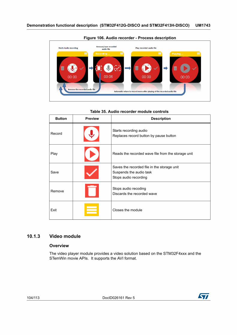
Demonstration functional description (STM32F412G-DISCO and STM32F413H-DISCO) UM1743
104/113 DocID026161 Rev 5
Figure 106. Audio recorder - Process description
10.1.3 Video module
Overview
The video player module provides a video solution based on the STM32F4xxx and the STemWin movie APIs. It supports the AVI format.
Table 35. Audio recorder module controls
Button Preview Description
Record
Starts recording audio
Replaces record button by pause button
Play Reads the recorded wave file from the storage unit
Save
Saves the recorded file in the storage unit
Suspends the audio task
Stops audio recording
RemoveStops audio recoding
Discards the recorded wave
Exit Closes the module

DocID026161 Rev 5 105/113
UM1743 Demonstration functional description (STM32F412G-DISCO and STM32F413H-DISCO)
112
Features
• Video Format: AVI
• Performance: frame rate up to 13 fps
• Video files stored in SD Card
Architecture
Figure 107 shows the different video player modules, and their connections and interactions with the external components.
Figure 107. Video recorder module architecture

Demonstration functional description (STM32F412G-DISCO and STM32F413H-DISCO) UM1743
106/113 DocID026161 Rev 5
Functional description
Start video recorder module by touching the audio recorder icon, as indicated in Figure 108. When the video player is started, the first AVI file stored in the storage unit starts playing.
Figure 108. Video recorder module startup
10.1.4 Analog clock module
Overview
The analog clock module enables to show and adjust the analog time by changing the RTC configuration.
Functional description
1. Start analog clock module by touching the analog clock icon (Figure 109).
Figure 109. Analog clock module startup
2. Press on settings button a first time to adjust minutes, and a second time to adjust hours (Figure 110).

DocID026161 Rev 5 107/113
UM1743 Demonstration functional description (STM32F412G-DISCO and STM32F413H-DISCO)
112
Figure 110. Analog clock setting
10.1.5 USB devices module
Overview
The USB device (USBD) module includes mass storage device application using the Micro SD memory.
Architecture
Figure 111 shows the different video player modules, and their connections and interactions with the external components.
Figure 111. USBD module architecture
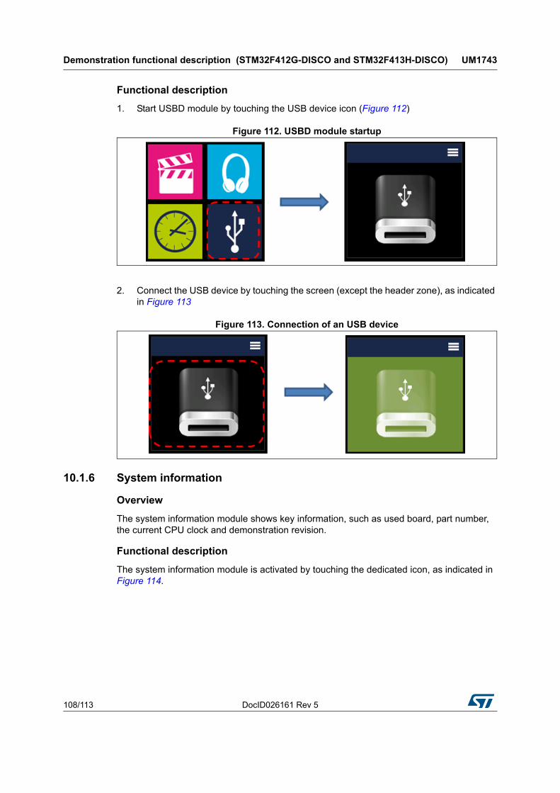
Demonstration functional description (STM32F412G-DISCO and STM32F413H-DISCO) UM1743
108/113 DocID026161 Rev 5
Functional description
1. Start USBD module by touching the USB device icon (Figure 112)
Figure 112. USBD module startup
2. Connect the USB device by touching the screen (except the header zone), as indicated in Figure 113
Figure 113. Connection of an USB device
10.1.6 System information
Overview
The system information module shows key information, such as used board, part number, the current CPU clock and demonstration revision.
Functional description
The system information module is activated by touching the dedicated icon, as indicated in Figure 114.

DocID026161 Rev 5 109/113
UM1743 Demonstration functional description (STM32F412G-DISCO and STM32F413H-DISCO)
112
Figure 114. System information module startup

Revision history UM1743
110/113 DocID026161 Rev 5
11 Revision history
Table 36. Document revision history
Date Revision Changes
24-Apr-2014 1 Initial release.
20-Mar-2015 2
Introduced STM32446E-EVAL demonstration.
Added:
– Figure 5: Startup window for STM32446E-EVAL, STM32F479I-EVAL, STM32F469I-DISCO, STM32F412G-DISCO and STM32F413H-DISCO demonstrations;
– Figure 7: Main desktop window for STM32446E-EVAL demonstration;
– Figure 14: Status bar for STM32446E-EVAL demonstration;
– Figure 16: Icon view widget for STM32446E-EVAL demonstration;
– Figure 19: Starting file execution for STM32446E-EVAL demonstration;
– Figure 23: Detection of storage units for STM32446E-EVAL demonstration;
– Figure 26: Memory heap for STM32CubeF4 demonstration;
– footnote 1 in Section 4.5: Module's direct open;
– note in Section 6: Performance.
Updated:
– Introduction and figure on Cover page;
– Section 3.1: Overview;
– Section 3.2: Kernel initialization;
– Section 3.3: Kernel processes and tasks;
– Section 3.8: Direct open feature;
– Figure 5: Startup window for STM32446E-EVAL, STM32F479I-EVAL, STM32F469I-DISCO, STM32F412G-DISCO and STM32F413H-DISCO demonstrations;
– Figure 28: STM32Cube demonstration boards;
– Section 3.12: Memory management;
– Section 3.16: Hardware settings;
– Table 7: Jumpers for different demonstration boards;
– Section 5.4.2: Touch screen configuration;
– Figure 58: EMF file generation.

DocID026161 Rev 5 111/113
UM1743 Revision history
112
09-Oct-2015 3
Introduced STM32F479I-EVAL and STM32F469I-DISCO boards.
Added:
– Section 3.5: ST widget add-ons and its subsections;
– Section 9: Demonstration functional description (STM32F479I-EVAL and STM32F469I-DISCO) and its subsections;
– Figure 8: Main desktop window for STM32479I-EVAL demonstration;
– Figure 9: Main desktop window for STM32469I-DISCO demonstration;
– Figure 11: Icon view widget;
– Figure 12: Slider skin;
– footnote 1 in Section 4.5: Module's direct open;
– notes in Section 3.11: Clock and date, Section 3.12: Memory management, Section 5.3: Touchscreen calibration and Section 6: Performance.
Updated:
– Introduction and figure on Cover page;
– Section 3.2: Kernel initialization;
– Section 3.3: Kernel processes and tasks;
– Section 3.6: Kernel menu management;
– Section 3.7: Modules manager;
– Section 3.8: Direct open feature;
– title of Figure 5: Startup window for STM32446E-EVAL, STM32F479I-EVAL, STM32F469I-DISCO, STM32F412G-DISCO and STM32F413H-DISCO demonstrations;
– Figure 28: STM32Cube demonstration boards;
– Section 3.12: Memory management;
– Section 3.16: Hardware settings;
– Table 7: Jumpers for different demonstration boards;
– Table 8: LCD frame buffer locations
– Section 5.4.2: Touch screen configuration.
15-Jul-2016 4
Introduced STM32F412G-Discovery board, hence added Section 10: Demonstration functional description (STM32F412G-DISCO and STM32F413H-DISCO) and its subsections.
Updated Introduction, Section 3.2: Kernel initialization, Section 3.3: Kernel processes and tasks, Section 3.6: Kernel menu management; Section 3.7: Modules manager, Section 3.12: Memory management, Section 3.16: Hardware settings, Section 5.2: Layers management and Section 5.4.2: Touch screen configuration.
Updated Table 7: Jumpers for different demonstration boards.
Updated image on cover page and Figure 28: STM32Cube demonstration boards.
Added Figure 10: Main desktop window for STM32412G-DISCO and STM32413H-DISCO demonstrations.
Updated caption of Figure 5: Startup window for STM32446E-EVAL, STM32F479I-EVAL, STM32F469I-DISCO, STM32F412G-DISCO and STM32F413H-DISCO demonstrations and of Table 32: VNC server module controls.
Table 36. Document revision history (continued)
Date Revision Changes

Revision history UM1743
112/113 DocID026161 Rev 5
22-Mar-2017 5
Introduced STM32F413H-Discovery board.
Updated Introduction, Section 3.6: Kernel menu management, Section 3.7: Modules manager, Section 3.16: Hardware settings, Section 5.4.2: Touch screen configuration and Section 10.1.1: Audio player.
Updated Note: in Section 3.11: Clock and date and title of Section 10: Demonstration functional description (STM32F412G-DISCO and STM32F413H-DISCO).
Updated image on cover page, Figure 1: STM32Cube block diagram and Figure 28: STM32Cube demonstration boards.
Added Figure 103: Board for beam-forming implementation, Figure 106: Audio recorder - Process description and Table 34: Audio player module voice controls.
Updated caption of Figure 5: Startup window for STM32446E-EVAL, STM32F479I-EVAL, STM32F469I-DISCO, STM32F412G-DISCO and STM32F413H-DISCO demonstrations and of Figure 10: Main desktop window for STM32412G-DISCO and STM32413H-DISCO demonstrations.
Updated Table 7: Jumpers for different demonstration boards, Table 33: Audio player module controls and Table 35: Audio recorder module controls.
Table 36. Document revision history (continued)
Date Revision Changes

DocID026161 Rev 5 113/113
UM1743
113
IMPORTANT NOTICE – PLEASE READ CAREFULLY
STMicroelectronics NV and its subsidiaries (“ST”) reserve the right to make changes, corrections, enhancements, modifications, and improvements to ST products and/or to this document at any time without notice. Purchasers should obtain the latest relevant information on ST products before placing orders. ST products are sold pursuant to ST’s terms and conditions of sale in place at the time of order acknowledgement.
Purchasers are solely responsible for the choice, selection, and use of ST products and ST assumes no liability for application assistance or the design of Purchasers’ products.
No license, express or implied, to any intellectual property right is granted by ST herein.
Resale of ST products with provisions different from the information set forth herein shall void any warranty granted by ST for such product.
ST and the ST logo are trademarks of ST. All other product or service names are the property of their respective owners.
Information in this document supersedes and replaces information previously supplied in any prior versions of this document.
© 2017 STMicroelectronics – All rights reserved