Embed Size (px)
Citation preview
February 2017 DocID027941 Rev 4 1/83
1
UM1906User manual
STM32CubeF7 demonstration platform
IntroductionThe STM32Cube initiative was originated by STMicroelectronics to ease developers’ life by reducing the development efforts, time and cost. STM32Cube covers the STM32 portfolio.
The STM32CubeF7 demonstration platform comes on top of the STM32Cube as a firmware package. It offers a full set of software components based on a module architecture that allows re-using them separately in standalone applications. All these modules are managed by the STM32CubeF7 demonstration kernel that dynamically adds new modules and accesses common resources (storage, graphical components and widgets, memory management, real-time operating system).
The STM32CubeF7 demonstration platform is built around the powerful graphical library STemWin and the FreeRTOS™ real-time operating system and uses almost the whole STM32 capability to offer a large scope of usage based on the STM32Cube HAL BSP and several middleware components.
The architecture was defined with the goal of making from the STM32CubeF7 demonstration core an independent central component which can be used with several RTOS and third party firmware libraries. It uses several abstraction layers inserted between the STM32CubeF7 demonstration core, the several modules and the libraries.
The STM32CubeF7 demonstrations support the STM32F7 Series devices and run on the STM32746G-EVAL, the STM32756G-EVAL, the STM32746G-Discovery, the STM32F769I-EVAL, the STM32F769I-Discovery and the STM32F723E-Discovery boards. All the demonstrations feature two modules (audio recorder and VNC server) which are not available on the STM327x6G-EVAL and STM32F723E-Discovery board demonstrations.
www.st.com

Contents UM1906
2/83 DocID027941 Rev 4
Contents
1 STM32Cube overview . . . . . . . . . . . . . . . . . . . . . . . . . . . . . . . . . . . . . . . 7
2 Global architecture . . . . . . . . . . . . . . . . . . . . . . . . . . . . . . . . . . . . . . . . . . 8
3 Kernel description . . . . . . . . . . . . . . . . . . . . . . . . . . . . . . . . . . . . . . . . . . . 9
3.1 Overview . . . . . . . . . . . . . . . . . . . . . . . . . . . . . . . . . . . . . . . . . . . . . . . . . . 9
3.2 Kernel initialization . . . . . . . . . . . . . . . . . . . . . . . . . . . . . . . . . . . . . . . . . . 10
3.3 Kernel processes and tasks . . . . . . . . . . . . . . . . . . . . . . . . . . . . . . . . . . . 10
3.4 Kernel graphical aspect . . . . . . . . . . . . . . . . . . . . . . . . . . . . . . . . . . . . . . .11
3.5 ST widget add-ons . . . . . . . . . . . . . . . . . . . . . . . . . . . . . . . . . . . . . . . . . . 13
3.5.1 ST animated icon view . . . . . . . . . . . . . . . . . . . . . . . . . . . . . . . . . . . . . . 13
3.5.2 ST slider skin . . . . . . . . . . . . . . . . . . . . . . . . . . . . . . . . . . . . . . . . . . . . . 14
3.6 Kernel menu management . . . . . . . . . . . . . . . . . . . . . . . . . . . . . . . . . . . . 14
3.7 Module manager . . . . . . . . . . . . . . . . . . . . . . . . . . . . . . . . . . . . . . . . . . . 16
3.8 Backup and settings configuration . . . . . . . . . . . . . . . . . . . . . . . . . . . . . . 17
3.9 Storage units . . . . . . . . . . . . . . . . . . . . . . . . . . . . . . . . . . . . . . . . . . . . . . 18
3.10 Adding a binary demonstration . . . . . . . . . . . . . . . . . . . . . . . . . . . . . . . . . 21
3.11 Demonstration repository . . . . . . . . . . . . . . . . . . . . . . . . . . . . . . . . . . . . 23
3.12 Kernel components . . . . . . . . . . . . . . . . . . . . . . . . . . . . . . . . . . . . . . . . . 24
3.13 Kernel core files . . . . . . . . . . . . . . . . . . . . . . . . . . . . . . . . . . . . . . . . . . . . 24
3.14 Hardware settings . . . . . . . . . . . . . . . . . . . . . . . . . . . . . . . . . . . . . . . . . . 25
4 Creating a new module . . . . . . . . . . . . . . . . . . . . . . . . . . . . . . . . . . . . . . 27
4.1 Creating the graphical aspect . . . . . . . . . . . . . . . . . . . . . . . . . . . . . . . . . . 27
4.2 Graphics customization . . . . . . . . . . . . . . . . . . . . . . . . . . . . . . . . . . . . . . 28
4.3 Module implementation . . . . . . . . . . . . . . . . . . . . . . . . . . . . . . . . . . . . . . 29
4.4 Adding a module to the main desktop . . . . . . . . . . . . . . . . . . . . . . . . . . . 30
5 Demonstration customization and configuration . . . . . . . . . . . . . . . . 31
5.1 LCD configuration . . . . . . . . . . . . . . . . . . . . . . . . . . . . . . . . . . . . . . . . . . . 31
5.2 Layer management . . . . . . . . . . . . . . . . . . . . . . . . . . . . . . . . . . . . . . . . . 31
5.3 BSP customization . . . . . . . . . . . . . . . . . . . . . . . . . . . . . . . . . . . . . . . . . . 32

DocID027941 Rev 4 3/83
UM1906 Contents
3
5.3.1 SDRAM configuration . . . . . . . . . . . . . . . . . . . . . . . . . . . . . . . . . . . . . . 32
5.3.2 Touch screen configuration . . . . . . . . . . . . . . . . . . . . . . . . . . . . . . . . . . 33
6 Performance . . . . . . . . . . . . . . . . . . . . . . . . . . . . . . . . . . . . . . . . . . . . . . 35
6.1 CPU cache . . . . . . . . . . . . . . . . . . . . . . . . . . . . . . . . . . . . . . . . . . . . . . . . 35
6.2 Multi buffering features . . . . . . . . . . . . . . . . . . . . . . . . . . . . . . . . . . . . . . 37
6.3 Multi layers feature . . . . . . . . . . . . . . . . . . . . . . . . . . . . . . . . . . . . . . . . . . 37
6.4 Hardware acceleration . . . . . . . . . . . . . . . . . . . . . . . . . . . . . . . . . . . . . . . 38
6.5 Hardware JPEG Decoding . . . . . . . . . . . . . . . . . . . . . . . . . . . . . . . . . . . . 39
7 Footprint . . . . . . . . . . . . . . . . . . . . . . . . . . . . . . . . . . . . . . . . . . . . . . . . . . 40
7.1 STemWin features resources . . . . . . . . . . . . . . . . . . . . . . . . . . . . . . . . . . 41
7.1.1 JPEG decoder . . . . . . . . . . . . . . . . . . . . . . . . . . . . . . . . . . . . . . . . . . . . 41
7.1.2 GUI Components . . . . . . . . . . . . . . . . . . . . . . . . . . . . . . . . . . . . . . . . . . 41
8 Demonstration functional description (part of STM32F7xxx boards) 43
8.1 Audio player . . . . . . . . . . . . . . . . . . . . . . . . . . . . . . . . . . . . . . . . . . . . . . . 43
8.2 Audio recorder . . . . . . . . . . . . . . . . . . . . . . . . . . . . . . . . . . . . . . . . . . . . . 48
8.3 VNC server . . . . . . . . . . . . . . . . . . . . . . . . . . . . . . . . . . . . . . . . . . . . . . . . 52
8.4 Video module . . . . . . . . . . . . . . . . . . . . . . . . . . . . . . . . . . . . . . . . . . . . . . 57
8.5 Game . . . . . . . . . . . . . . . . . . . . . . . . . . . . . . . . . . . . . . . . . . . . . . . . . . . . 66
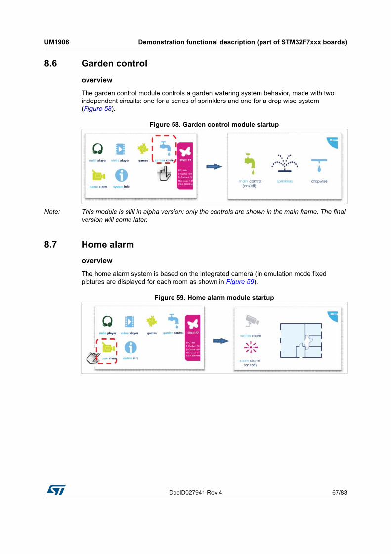
8.6 Garden control . . . . . . . . . . . . . . . . . . . . . . . . . . . . . . . . . . . . . . . . . . . . . 67
8.7 Home alarm . . . . . . . . . . . . . . . . . . . . . . . . . . . . . . . . . . . . . . . . . . . . . . . 67
8.8 System Information . . . . . . . . . . . . . . . . . . . . . . . . . . . . . . . . . . . . . . . . . 68
8.9 Touch GFX . . . . . . . . . . . . . . . . . . . . . . . . . . . . . . . . . . . . . . . . . . . . . . . . 68
8.10 Embedded wizard . . . . . . . . . . . . . . . . . . . . . . . . . . . . . . . . . . . . . . . . . . . 70
9 Demonstration functional description (STM32F723E-Discovery) . . . 72
9.1 Audio player . . . . . . . . . . . . . . . . . . . . . . . . . . . . . . . . . . . . . . . . . . . . . . . 72
9.2 Audio recorder . . . . . . . . . . . . . . . . . . . . . . . . . . . . . . . . . . . . . . . . . . . . . 75
9.3 Video module . . . . . . . . . . . . . . . . . . . . . . . . . . . . . . . . . . . . . . . . . . . . . . 78
9.4 Analog Clock module . . . . . . . . . . . . . . . . . . . . . . . . . . . . . . . . . . . . . . . . 79
9.5 System Information . . . . . . . . . . . . . . . . . . . . . . . . . . . . . . . . . . . . . . . . . 80
10 Revision history . . . . . . . . . . . . . . . . . . . . . . . . . . . . . . . . . . . . . . . . . . . 81
List of tables UM1906
4/83 DocID027941 Rev 4
List of tables
Table 1. File system interface functions . . . . . . . . . . . . . . . . . . . . . . . . . . . . . . . . . . . . . . . . . . . . . . 18Table 2. File system interface APIs . . . . . . . . . . . . . . . . . . . . . . . . . . . . . . . . . . . . . . . . . . . . . . . . . 19Table 3. Kernel components list . . . . . . . . . . . . . . . . . . . . . . . . . . . . . . . . . . . . . . . . . . . . . . . . . . . . 24Table 4. Kernel core files list. . . . . . . . . . . . . . . . . . . . . . . . . . . . . . . . . . . . . . . . . . . . . . . . . . . . . . . 24Table 5. STM327x6G-EVAL and STM32F769I-EVAL board jumper configuration for
demonstration . . . . . . . . . . . . . . . . . . . . . . . . . . . . . . . . . . . . . . . . . . . . . . . . . . . . . . . . . . . 26Table 6. LCD frame buffer locations . . . . . . . . . . . . . . . . . . . . . . . . . . . . . . . . . . . . . . . . . . . . . . . . . 32Table 7. Memory dedicated for I/D cache for each device family . . . . . . . . . . . . . . . . . . . . . . . . . . . 35Table 8. Module footprint . . . . . . . . . . . . . . . . . . . . . . . . . . . . . . . . . . . . . . . . . . . . . . . . . . . . . . . . . 40Table 9. RAM requirements for some JPEG resolutions . . . . . . . . . . . . . . . . . . . . . . . . . . . . . . . . . 41Table 10. MemoSTemWin components memory requirements . . . . . . . . . . . . . . . . . . . . . . . . . . . . . 41Table 11. Widget memory requirements. . . . . . . . . . . . . . . . . . . . . . . . . . . . . . . . . . . . . . . . . . . . . . . 42Table 12. Audio module controls . . . . . . . . . . . . . . . . . . . . . . . . . . . . . . . . . . . . . . . . . . . . . . . . . . . . 47Table 13. Audio module controls . . . . . . . . . . . . . . . . . . . . . . . . . . . . . . . . . . . . . . . . . . . . . . . . . . . . 52Table 14. VNC server module controls . . . . . . . . . . . . . . . . . . . . . . . . . . . . . . . . . . . . . . . . . . . . . . . . 57Table 15. Video module controls . . . . . . . . . . . . . . . . . . . . . . . . . . . . . . . . . . . . . . . . . . . . . . . . . . . . 62Table 16. Batch file description. . . . . . . . . . . . . . . . . . . . . . . . . . . . . . . . . . . . . . . . . . . . . . . . . . . . . . 64Table 17. Variable description . . . . . . . . . . . . . . . . . . . . . . . . . . . . . . . . . . . . . . . . . . . . . . . . . . . . . . 65Table 18. Parameter description. . . . . . . . . . . . . . . . . . . . . . . . . . . . . . . . . . . . . . . . . . . . . . . . . . . . . 65Table 19. Audio player module controls . . . . . . . . . . . . . . . . . . . . . . . . . . . . . . . . . . . . . . . . . . . . . . . 74Table 20. Audio recorder module controls . . . . . . . . . . . . . . . . . . . . . . . . . . . . . . . . . . . . . . . . . . . . . 77Table 21. Document revision history . . . . . . . . . . . . . . . . . . . . . . . . . . . . . . . . . . . . . . . . . . . . . . . . . 81
DocID027941 Rev 4 5/83
UM1906 List of figures
6
List of figures
Figure 1. STM32Cube block diagram . . . . . . . . . . . . . . . . . . . . . . . . . . . . . . . . . . . . . . . . . . . . . . . . . 7Figure 2. STM32CubeF7 demonstration overview . . . . . . . . . . . . . . . . . . . . . . . . . . . . . . . . . . . . . . . 8Figure 3. Kernel components and services . . . . . . . . . . . . . . . . . . . . . . . . . . . . . . . . . . . . . . . . . . . . . 9Figure 4. Startup window . . . . . . . . . . . . . . . . . . . . . . . . . . . . . . . . . . . . . . . . . . . . . . . . . . . . . . . . . . 11Figure 5. Main desktop window for the STM32756G-EVAL, the STM32746G-Discovery,
the STM32F769I-EVAL and the STM32F769I-Discovery demonstrations . . . . . . . . . . . . . 12Figure 6. Main desktop window for the STM32F723E-Discovery demonstrations. . . . . . . . . . . . . . . 12Figure 7. ST animated icon view . . . . . . . . . . . . . . . . . . . . . . . . . . . . . . . . . . . . . . . . . . . . . . . . . . . . 13Figure 8. Slider skin . . . . . . . . . . . . . . . . . . . . . . . . . . . . . . . . . . . . . . . . . . . . . . . . . . . . . . . . . . . . . . 14Figure 9. Icon view widget . . . . . . . . . . . . . . . . . . . . . . . . . . . . . . . . . . . . . . . . . . . . . . . . . . . . . . . . . 14Figure 10. Functionalities and properties of modules . . . . . . . . . . . . . . . . . . . . . . . . . . . . . . . . . . . . . 16Figure 11. Available storage units . . . . . . . . . . . . . . . . . . . . . . . . . . . . . . . . . . . . . . . . . . . . . . . . . . . . 18Figure 12. Software architecture . . . . . . . . . . . . . . . . . . . . . . . . . . . . . . . . . . . . . . . . . . . . . . . . . . . . . 20Figure 13. Demonstration memory mapping . . . . . . . . . . . . . . . . . . . . . . . . . . . . . . . . . . . . . . . . . . . . 21Figure 14. Folder structure. . . . . . . . . . . . . . . . . . . . . . . . . . . . . . . . . . . . . . . . . . . . . . . . . . . . . . . . . . 23Figure 15. STM32Cube demonstration board . . . . . . . . . . . . . . . . . . . . . . . . . . . . . . . . . . . . . . . . . . . 25Figure 16. GUI builder overview . . . . . . . . . . . . . . . . . . . . . . . . . . . . . . . . . . . . . . . . . . . . . . . . . . . . . 27Figure 17. Graphics customization . . . . . . . . . . . . . . . . . . . . . . . . . . . . . . . . . . . . . . . . . . . . . . . . . . . 28Figure 18. LCDConf location . . . . . . . . . . . . . . . . . . . . . . . . . . . . . . . . . . . . . . . . . . . . . . . . . . . . . . . . 31Figure 19. SDRAM initialization . . . . . . . . . . . . . . . . . . . . . . . . . . . . . . . . . . . . . . . . . . . . . . . . . . . . . . 32Figure 20. Touch screen configuration . . . . . . . . . . . . . . . . . . . . . . . . . . . . . . . . . . . . . . . . . . . . . . . . 33Figure 21. STM32F7 Series system architecture. . . . . . . . . . . . . . . . . . . . . . . . . . . . . . . . . . . . . . . . . 35Figure 22. STM32F7 Series device performance versus STM32F4 Series device . . . . . . . . . . . . . . . 36Figure 23. Example of tearing effect . . . . . . . . . . . . . . . . . . . . . . . . . . . . . . . . . . . . . . . . . . . . . . . . . . 37Figure 24. Independent layer management . . . . . . . . . . . . . . . . . . . . . . . . . . . . . . . . . . . . . . . . . . . . . 38Figure 25. Hardware JPEG decoding . . . . . . . . . . . . . . . . . . . . . . . . . . . . . . . . . . . . . . . . . . . . . . . . . 39Figure 26. Audio player module architecture . . . . . . . . . . . . . . . . . . . . . . . . . . . . . . . . . . . . . . . . . . . . 44Figure 27. Audio player process . . . . . . . . . . . . . . . . . . . . . . . . . . . . . . . . . . . . . . . . . . . . . . . . . . . . . 45Figure 28. Audio player module startup . . . . . . . . . . . . . . . . . . . . . . . . . . . . . . . . . . . . . . . . . . . . . . . . 45Figure 29. Audio player playlist . . . . . . . . . . . . . . . . . . . . . . . . . . . . . . . . . . . . . . . . . . . . . . . . . . . . . . 46Figure 30. Equalizer frame. . . . . . . . . . . . . . . . . . . . . . . . . . . . . . . . . . . . . . . . . . . . . . . . . . . . . . . . . . 46Figure 31. Hardware connectivity . . . . . . . . . . . . . . . . . . . . . . . . . . . . . . . . . . . . . . . . . . . . . . . . . . . . 46Figure 32. Audio recorder module architecture . . . . . . . . . . . . . . . . . . . . . . . . . . . . . . . . . . . . . . . . . . 49Figure 33. Audio recorder module startup . . . . . . . . . . . . . . . . . . . . . . . . . . . . . . . . . . . . . . . . . . . . . . 49Figure 34. Start audio recording . . . . . . . . . . . . . . . . . . . . . . . . . . . . . . . . . . . . . . . . . . . . . . . . . . . . . 50Figure 35. Stop audio recording. . . . . . . . . . . . . . . . . . . . . . . . . . . . . . . . . . . . . . . . . . . . . . . . . . . . . . 50Figure 36. Play the recorded wave . . . . . . . . . . . . . . . . . . . . . . . . . . . . . . . . . . . . . . . . . . . . . . . . . . . 51Figure 37. Hardware connectivity . . . . . . . . . . . . . . . . . . . . . . . . . . . . . . . . . . . . . . . . . . . . . . . . . . . . 51Figure 38. Video player module architecture . . . . . . . . . . . . . . . . . . . . . . . . . . . . . . . . . . . . . . . . . . . . 53Figure 39. VNC server module startup . . . . . . . . . . . . . . . . . . . . . . . . . . . . . . . . . . . . . . . . . . . . . . . . 54Figure 40. Enable/disable secure mode . . . . . . . . . . . . . . . . . . . . . . . . . . . . . . . . . . . . . . . . . . . . . . . 54Figure 41. Start VNC server. . . . . . . . . . . . . . . . . . . . . . . . . . . . . . . . . . . . . . . . . . . . . . . . . . . . . . . . . 54Figure 42. Assigned IP address. . . . . . . . . . . . . . . . . . . . . . . . . . . . . . . . . . . . . . . . . . . . . . . . . . . . . . 55Figure 43. Entering IP address . . . . . . . . . . . . . . . . . . . . . . . . . . . . . . . . . . . . . . . . . . . . . . . . . . . . . . 55Figure 44. Start VNC connection entering the password . . . . . . . . . . . . . . . . . . . . . . . . . . . . . . . . . . 55Figure 45. Background mode. . . . . . . . . . . . . . . . . . . . . . . . . . . . . . . . . . . . . . . . . . . . . . . . . . . . . . . . 56Figure 46. HW connectivity . . . . . . . . . . . . . . . . . . . . . . . . . . . . . . . . . . . . . . . . . . . . . . . . . . . . . . . . . 56Figure 47. Video player module architecture . . . . . . . . . . . . . . . . . . . . . . . . . . . . . . . . . . . . . . . . . . . . 58
List of figures UM1906
6/83 DocID027941 Rev 4
Figure 48. Video player process . . . . . . . . . . . . . . . . . . . . . . . . . . . . . . . . . . . . . . . . . . . . . . . . . . . . . 59Figure 49. Video player module startup . . . . . . . . . . . . . . . . . . . . . . . . . . . . . . . . . . . . . . . . . . . . . . . . 59Figure 50. Video player playlist . . . . . . . . . . . . . . . . . . . . . . . . . . . . . . . . . . . . . . . . . . . . . . . . . . . . . . 60Figure 51. Video player playlist popup. . . . . . . . . . . . . . . . . . . . . . . . . . . . . . . . . . . . . . . . . . . . . . . . . 60Figure 52. Video player frame . . . . . . . . . . . . . . . . . . . . . . . . . . . . . . . . . . . . . . . . . . . . . . . . . . . . . . . 61Figure 53. Video player control keys . . . . . . . . . . . . . . . . . . . . . . . . . . . . . . . . . . . . . . . . . . . . . . . . . . 61Figure 54. EMF generation environment . . . . . . . . . . . . . . . . . . . . . . . . . . . . . . . . . . . . . . . . . . . . . . . 63Figure 55. JPEG2Movie overview . . . . . . . . . . . . . . . . . . . . . . . . . . . . . . . . . . . . . . . . . . . . . . . . . . . . 63Figure 56. EMF file generation. . . . . . . . . . . . . . . . . . . . . . . . . . . . . . . . . . . . . . . . . . . . . . . . . . . . . . . 64Figure 57. Reversi game module startup. . . . . . . . . . . . . . . . . . . . . . . . . . . . . . . . . . . . . . . . . . . . . . . 66Figure 58. Garden control module startup . . . . . . . . . . . . . . . . . . . . . . . . . . . . . . . . . . . . . . . . . . . . . . 67Figure 59. Home alarm module startup . . . . . . . . . . . . . . . . . . . . . . . . . . . . . . . . . . . . . . . . . . . . . . . . 67Figure 60. Home camera startup . . . . . . . . . . . . . . . . . . . . . . . . . . . . . . . . . . . . . . . . . . . . . . . . . . . . . 68Figure 61. System information startup . . . . . . . . . . . . . . . . . . . . . . . . . . . . . . . . . . . . . . . . . . . . . . . . . 68Figure 62. Touch-GFX demonstration startup . . . . . . . . . . . . . . . . . . . . . . . . . . . . . . . . . . . . . . . . . . . 69Figure 63. Touch-GFX demonstration modules. . . . . . . . . . . . . . . . . . . . . . . . . . . . . . . . . . . . . . . . . . 69Figure 64. Video/audio player module . . . . . . . . . . . . . . . . . . . . . . . . . . . . . . . . . . . . . . . . . . . . . . . . . 70Figure 65. Embedded wizard demonstration startup . . . . . . . . . . . . . . . . . . . . . . . . . . . . . . . . . . . . . . 71Figure 66. Embedded wizard demonstration modules. . . . . . . . . . . . . . . . . . . . . . . . . . . . . . . . . . . . . 71Figure 67. Audio player module architecture . . . . . . . . . . . . . . . . . . . . . . . . . . . . . . . . . . . . . . . . . . . . 73Figure 68. Audio player module startup . . . . . . . . . . . . . . . . . . . . . . . . . . . . . . . . . . . . . . . . . . . . . . . . 74Figure 69. Audio recorder module architecture . . . . . . . . . . . . . . . . . . . . . . . . . . . . . . . . . . . . . . . . . . 76Figure 70. Audio recorder module startup . . . . . . . . . . . . . . . . . . . . . . . . . . . . . . . . . . . . . . . . . . . . . . 76Figure 71. Audio recorder module process . . . . . . . . . . . . . . . . . . . . . . . . . . . . . . . . . . . . . . . . . . . . . 77Figure 72. Video player module architecture . . . . . . . . . . . . . . . . . . . . . . . . . . . . . . . . . . . . . . . . . . . . 78Figure 73. Video player module startup . . . . . . . . . . . . . . . . . . . . . . . . . . . . . . . . . . . . . . . . . . . . . . . . 79Figure 74. Analog clock module startup. . . . . . . . . . . . . . . . . . . . . . . . . . . . . . . . . . . . . . . . . . . . . . . . 79Figure 75. Analog clock settings . . . . . . . . . . . . . . . . . . . . . . . . . . . . . . . . . . . . . . . . . . . . . . . . . . . . . 80Figure 76. System information module startup . . . . . . . . . . . . . . . . . . . . . . . . . . . . . . . . . . . . . . . . . . 80
DocID027941 Rev 4 7/83
UM1906 STM32Cube overview
82
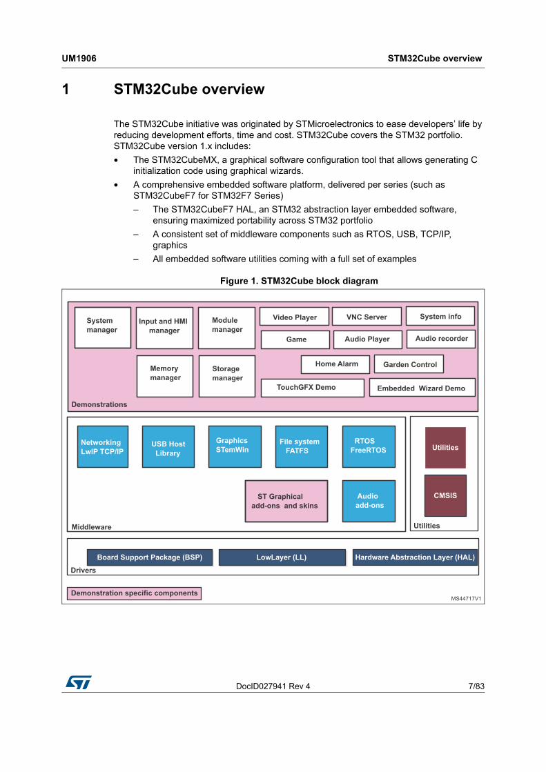
1 STM32Cube overview
The STM32Cube initiative was originated by STMicroelectronics to ease developers’ life by reducing development efforts, time and cost. STM32Cube covers the STM32 portfolio. STM32Cube version 1.x includes:
• The STM32CubeMX, a graphical software configuration tool that allows generating C initialization code using graphical wizards.
• A comprehensive embedded software platform, delivered per series (such as STM32CubeF7 for STM32F7 Series)
– The STM32CubeF7 HAL, an STM32 abstraction layer embedded software, ensuring maximized portability across STM32 portfolio
– A consistent set of middleware components such as RTOS, USB, TCP/IP, graphics
– All embedded software utilities coming with a full set of examples
Figure 1. STM32Cube block diagram
Global architecture UM1906
8/83 DocID027941 Rev 4
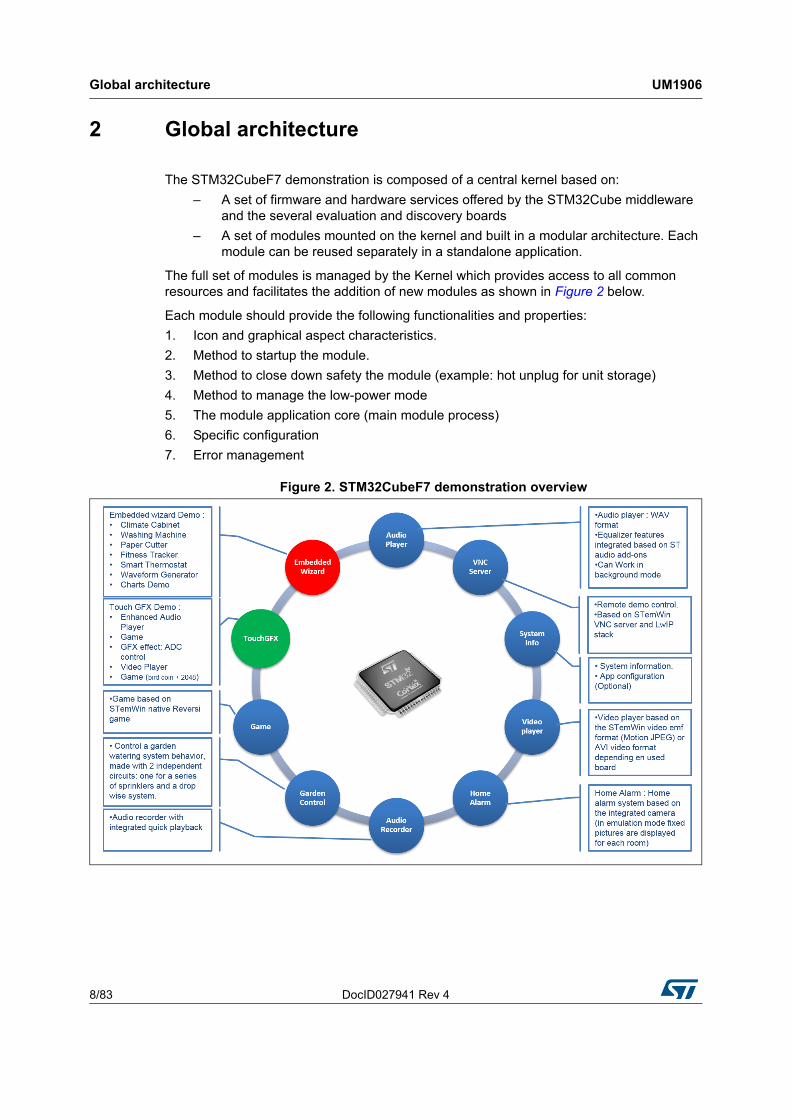
2 Global architecture
The STM32CubeF7 demonstration is composed of a central kernel based on:
– A set of firmware and hardware services offered by the STM32Cube middleware and the several evaluation and discovery boards
– A set of modules mounted on the kernel and built in a modular architecture. Each module can be reused separately in a standalone application.
The full set of modules is managed by the Kernel which provides access to all common resources and facilitates the addition of new modules as shown in Figure 2 below.
Each module should provide the following functionalities and properties:
1. Icon and graphical aspect characteristics.
2. Method to startup the module.
3. Method to close down safety the module (example: hot unplug for unit storage)
4. Method to manage the low-power mode
5. The module application core (main module process)
6. Specific configuration
7. Error management
Figure 2. STM32CubeF7 demonstration overview
DocID027941 Rev 4 9/83
UM1906 Kernel description
82
3 Kernel description
3.1 Overview
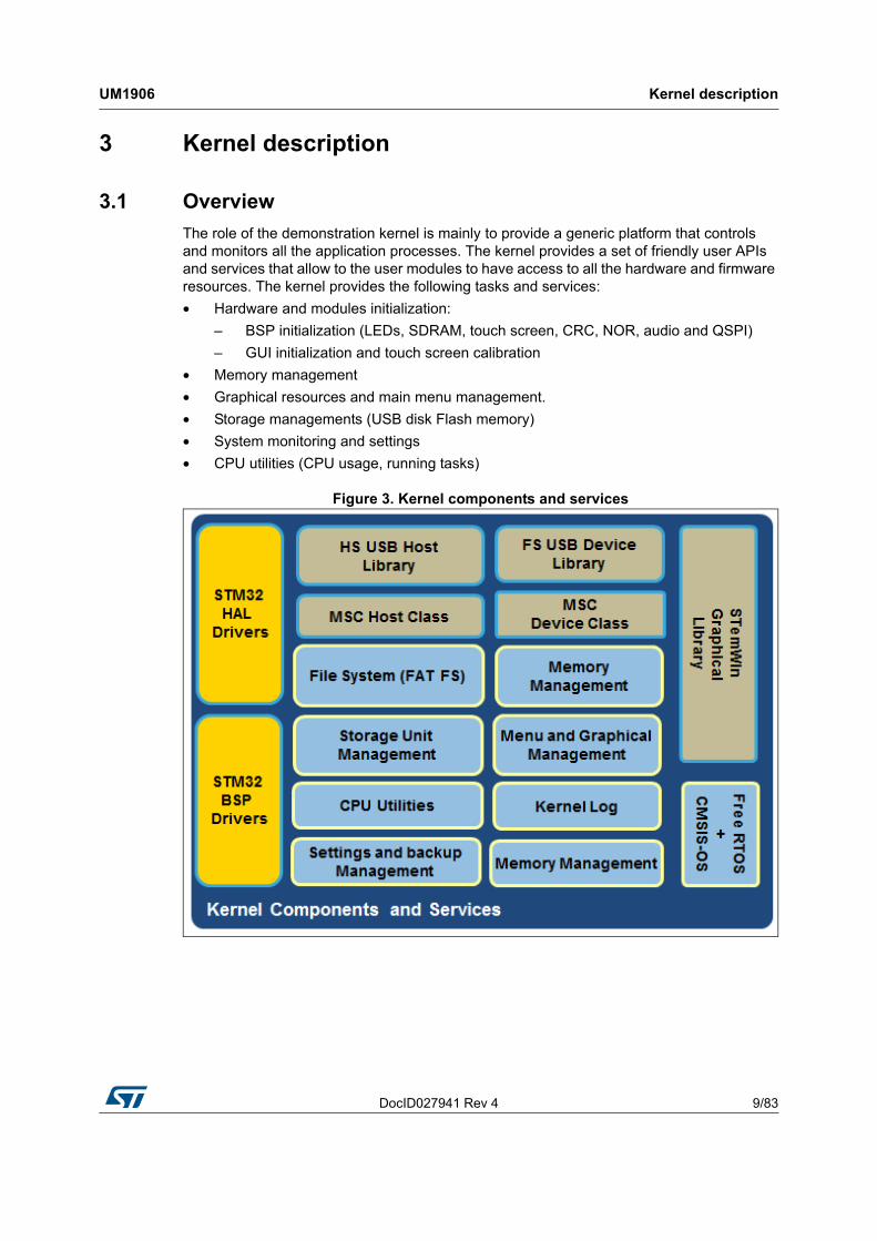
The role of the demonstration kernel is mainly to provide a generic platform that controls and monitors all the application processes. The kernel provides a set of friendly user APIs and services that allow to the user modules to have access to all the hardware and firmware resources. The kernel provides the following tasks and services:
• Hardware and modules initialization:
– BSP initialization (LEDs, SDRAM, touch screen, CRC, NOR, audio and QSPI)
– GUI initialization and touch screen calibration
• Memory management
• Graphical resources and main menu management.
• Storage managements (USB disk Flash memory)
• System monitoring and settings
• CPU utilities (CPU usage, running tasks)
Figure 3. Kernel components and services
Kernel description UM1906
10/83 DocID027941 Rev 4
3.2 Kernel initialization
The first task of the kernel is to initialize the hardware and firmware resources to make them available to its internal processes and the modules around it. The kernel starts by initializing the HAL, system clocks and then the hardware resources needed during the middleware components:
• LEDs and touchscreen
• SDRAM
• NOR Flash memory
• QSPI memory
• Backup SRAM
• RTC
Note: In the case of the STM32746G-EVAL board, the NOR memory is used to store graphical icons and animated GIF and bitmaps for the overall demonstration otherwise the external QSPI memory is used.
Once the low level resources are initialized, the kernel performs the STemWin GUI library initialization and prepares the following common services:
• Storage units
• Module manager
Upon the full initialization phase, the kernel adds and links the system and user modules to the demonstration core.
Note: Not all the hardware resources can be used in all the demonstration platforms, according to the availability and to the integrated modules.
3.3 Kernel processes and tasks
The kernel is composed of two main tasks managed by FreeRTOS through the CMSIS-OS wrapping layer:
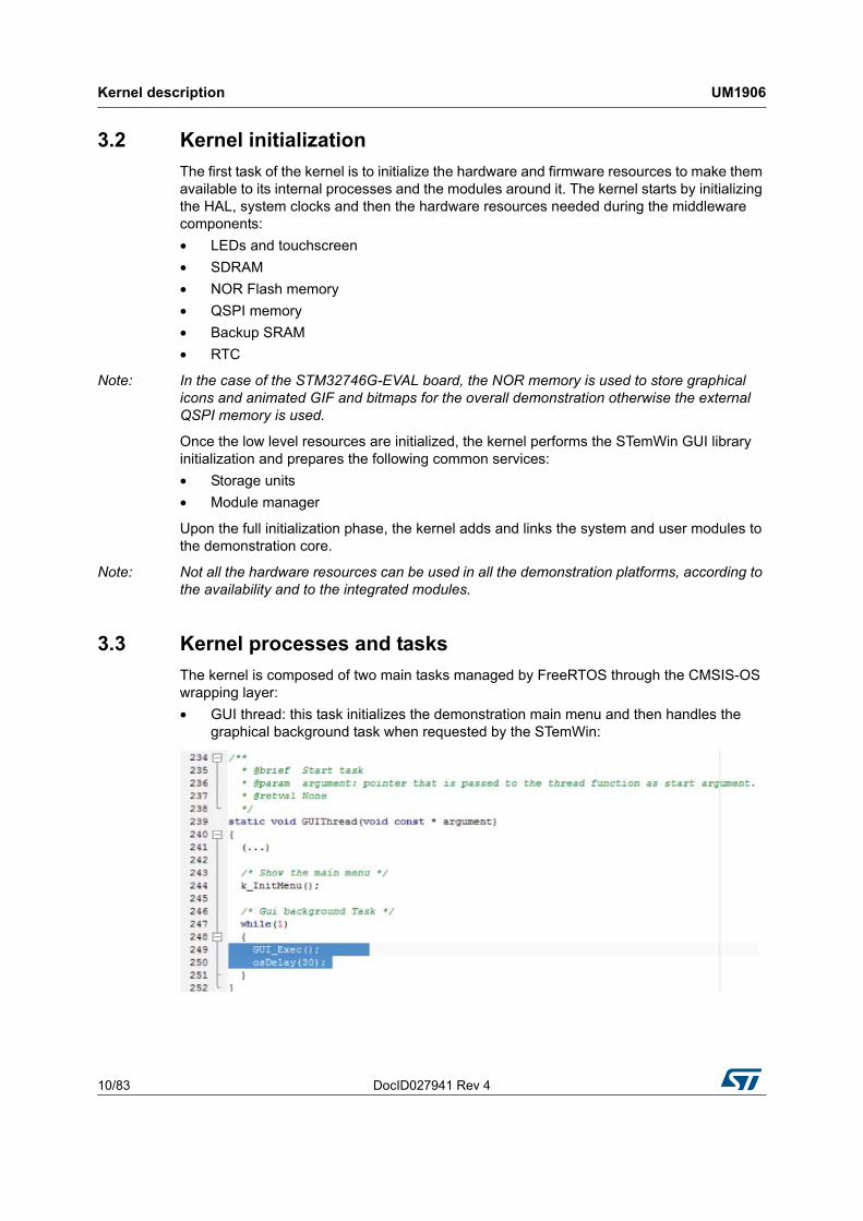
• GUI thread: this task initializes the demonstration main menu and then handles the graphical background task when requested by the STemWin:
DocID027941 Rev 4 11/83
UM1906 Kernel description
82
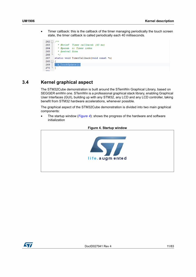
• Timer callback: this is the callback of the timer managing periodically the touch screen state, the timer callback is called periodically each 40 milliseconds.
3.4 Kernel graphical aspect
The STM32Cube demonstration is built around the STemWin Graphical Library, based on SEGGER emWin one. STemWin is a professional graphical stack library, enabling Graphical User Interfaces (GUI), building up with any STM32, any LCD and any LCD controller, taking benefit from STM32 hardware accelerations, whenever possible.
The graphical aspect of the STM32Cube demonstration is divided into two main graphical components:
• The startup window (Figure 4): shows the progress of the hardware and software initialization
Figure 4. Startup window
Kernel description UM1906
12/83 DocID027941 Rev 4
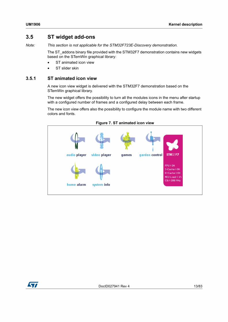
• The main desktop (shown in Figure 5 and Figure 6), that handles the main demonstration menu and the numerous kernel and modules control.
Figure 5. Main desktop window for the STM32756G-EVAL, the STM32746G-Discovery,the STM32F769I-EVAL and the STM32F769I-Discovery demonstrations
Figure 6. Main desktop window for the STM32F723E-Discovery demonstrations
DocID027941 Rev 4 13/83
UM1906 Kernel description
82
3.5 ST widget add-ons
Note: This section is not applicable for the STM32F723E-Discovery demonstration.
The ST_addons binary file provided with the STM32F7 demonstration contains new widgets based on the STemWin graphical library:
• ST animated icon view
• ST slider skin
3.5.1 ST animated icon view
A new icon view widget is delivered with the STM32F7 demonstration based on the STemWin graphical library.
The new widget offers the possibility to turn all the modules icons in the menu after startup with a configured number of frames and a configured delay between each frame.
The new icon view offers also the possibility to configure the module name with two different colors and fonts.
Figure 7. ST animated icon view

Kernel description UM1906
14/83 DocID027941 Rev 4
3.5.2 ST slider skin
A new slider skin is delivered with the STM32F7 demonstration based on the STemWin graphical library.
The new skin offers the possibility to change the slider color and the behavior as shown in Figure 8.
Figure 8. Slider skin
3.6 Kernel menu management
The main demonstration menu is initialized and launched by the GUI thread. Before the initialization of the menu, the following actions are performed:
• Draw the background image
• Restore general settings from backup memory.
• Setup the main desktop callback to manage main window messages.
The icon view widget: contains the icons associated to added modules. The user can launch a module by a simple click on the module icon.
Figure 9. Icon view widget
DocID027941 Rev 4 15/83
UM1906 Kernel description
82
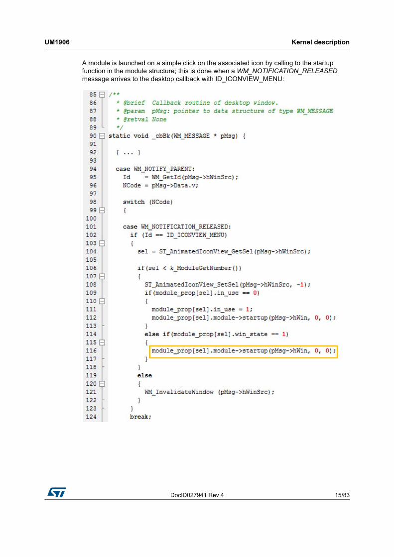
A module is launched on a simple click on the associated icon by calling to the startup function in the module structure; this is done when a WM_NOTIFICATION_RELEASED message arrives to the desktop callback with ID_ICONVIEW_MENU:

Kernel description UM1906
16/83 DocID027941 Rev 4
3.7 Module manager
The modules are managed by the kernel which is responsible of initializing the modules, initializing hardware and GUI resources relative to the modules and initializing the common resources such as the storage unit, the graphical widgets and the system menu.
Figure 10. Functionalities and properties of modules
Each module should provide the following functionalities and properties:
1. Icon and graphical component structure
2. Method to startup the module
3. Method to close down safety the module (example: Hot unplug for MS Flash disk)
4. Method to manage low-power mode (optional)
5. The Application task
6. The module background process (optional)
7. Remote control method (optional)
8. Specific configuration
9. Error management
The modules can be added in run time to the demonstration by using the common kernel resources. The following code shows how to add a module to the demonstration:
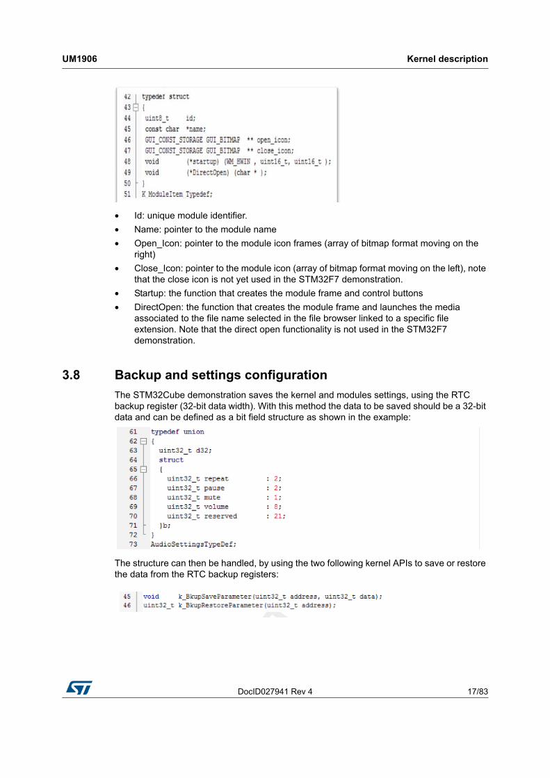
A module is a set of function and data structures that are defined in a data structure that provides all the information and pointers to specific methods and functions to the kernel. This later checks the integrity and the validity of the module and inserts its structure into a module table. Each module is identified by a unique ID. When two modules have the same UID, the kernel rejects the second one. The module structure is defined as follows:
DocID027941 Rev 4 17/83
UM1906 Kernel description
82
• Id: unique module identifier.
• Name: pointer to the module name
• Open_Icon: pointer to the module icon frames (array of bitmap format moving on the right)
• Close_Icon: pointer to the module icon (array of bitmap format moving on the left), note that the close icon is not yet used in the STM32F7 demonstration.
• Startup: the function that creates the module frame and control buttons
• DirectOpen: the function that creates the module frame and launches the media associated to the file name selected in the file browser linked to a specific file extension. Note that the direct open functionality is not used in the STM32F7 demonstration.
3.8 Backup and settings configuration
The STM32Cube demonstration saves the kernel and modules settings, using the RTC backup register (32-bit data width). With this method the data to be saved should be a 32-bit data and can be defined as a bit field structure as shown in the example:
The structure can then be handled, by using the two following kernel APIs to save or restore the data from the RTC backup registers:
Kernel description UM1906
18/83 DocID027941 Rev 4
3.9 Storage units
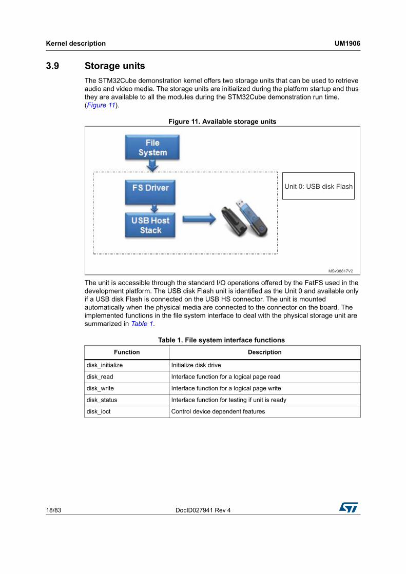
The STM32Cube demonstration kernel offers two storage units that can be used to retrieve audio and video media. The storage units are initialized during the platform startup and thus they are available to all the modules during the STM32Cube demonstration run time. (Figure 11).
Figure 11. Available storage units
The unit is accessible through the standard I/O operations offered by the FatFS used in the development platform. The USB disk Flash unit is identified as the Unit 0 and available only if a USB disk Flash is connected on the USB HS connector. The unit is mounted automatically when the physical media are connected to the connector on the board. The implemented functions in the file system interface to deal with the physical storage unit are summarized in Table 1.
Table 1. File system interface functions
Function Description
disk_initialize Initialize disk drive
disk_read Interface function for a logical page read
disk_write Interface function for a logical page write
disk_status Interface function for testing if unit is ready
disk_ioct Control device dependent features
DocID027941 Rev 4 19/83
UM1906 Kernel description
82
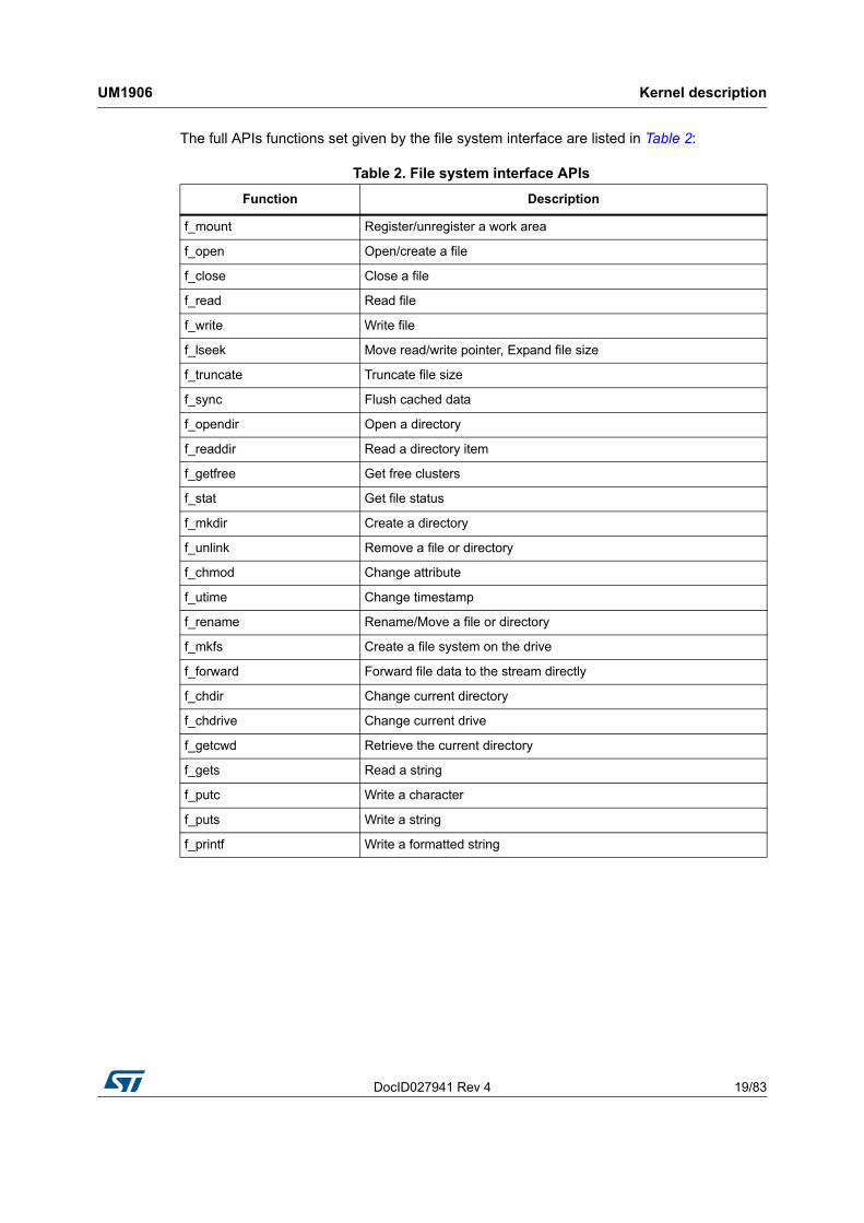
The full APIs functions set given by the file system interface are listed in Table 2:
Table 2. File system interface APIs
Function Description
f_mount Register/unregister a work area
f_open Open/create a file
f_close Close a file
f_read Read file
f_write Write file
f_lseek Move read/write pointer, Expand file size
f_truncate Truncate file size
f_sync Flush cached data
f_opendir Open a directory
f_readdir Read a directory item
f_getfree Get free clusters
f_stat Get file status
f_mkdir Create a directory
f_unlink Remove a file or directory
f_chmod Change attribute
f_utime Change timestamp
f_rename Rename/Move a file or directory
f_mkfs Create a file system on the drive
f_forward Forward file data to the stream directly
f_chdir Change current directory
f_chdrive Change current drive
f_getcwd Retrieve the current directory
f_gets Read a string
f_putc Write a character
f_puts Write a string
f_printf Write a formatted string

Kernel description UM1906
20/83 DocID027941 Rev 4
For the FAT FS file system, the page size is fixed to 512 bytes. The USB disk flashes with a higher page size are not supported.
The storage unit is built around the USB host library in high speed, the software architecture is shown in Figure 12.
Figure 12. Software architecture
The FatFS is mounted upon the USB host mass storage class to allow an abstract access to the physical media through standard I/O methods.
DocID027941 Rev 4 21/83
UM1906 Kernel description
82
3.10 Adding a binary demonstration
The user can load a specific demonstration as a binary in a specific memory address. The specific demonstration is launched during the run-time of the native ST demonstration. The main demonstration (ST demonstration) jumps to the specific demonstration address. From the specific demonstration, the user can go back to the main demonstration by doing a hardware reset.
The specific demonstration must provide a control button named “Menu” that triggers a hardware reset and saves a specific signature in the backup SRAM.
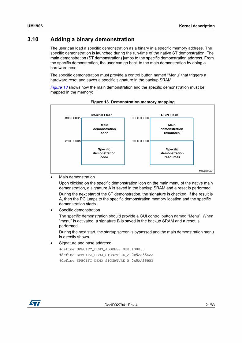
Figure 13 shows how the main demonstration and the specific demonstration must be mapped in the memory:
Figure 13. Demonstration memory mapping
• Main demonstration
Upon clicking on the specific demonstration icon on the main menu of the native main demonstration, a signature A is saved in the backup SRAM and a reset is performed.
During the next start of the ST demonstration, the signature is checked. If the result is A, then the PC jumps to the specific demonstration memory location and the specific demonstration starts.
• Specific demonstration
The specific demonstration should provide a GUI control button named “Menu”. When “menu” is activated, a signature B is saved in the backup SRAM and a reset is performed.
During the next start, the startup screen is bypassed and the main demonstration menu is directly shown.
• Signature and base address:
#define SPECIFC_DEMO_ADDRESS 0x08100000
#define SPECIFC_DEMO_SIGNATURE_A 0x5AA55AAA
#define SPECIFC_DEMO_SIGNATURE_B 0x5AA55BBB
Kernel description UM1906
22/83 DocID027941 Rev 4
The Reset sequence must be done as follows:
__HAL_RCC_RTC_ENABLE();
__HAL_RCC_PWR_CLK_ENABLE();
__HAL_RCC_BKPSRAM_CLK_ENABLE();
HAL_PWR_EnableBkUpAccess();
(...)
*(uint32_t *)(0x40024000) = SPECIFIC_DEMO_SIGNATURE_B;
NVIC_SystemReset();
The vector table defined in the "system_stm32fxxx" as follows:
SCB->VTOR = FLASH_BASE | VECT_TAB_OFFSET
#define VECT_TAB_OFFSET 0x00
needs to be reallocated by updating the VECT_TAB_OFFSET value
#define VECT_TAB_OFFSET 0x100000
DocID027941 Rev 4 23/83
UM1906 Kernel description
82
3.11 Demonstration repository
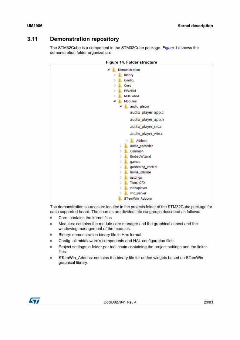
The STM32Cube is a component in the STM32Cube package. Figure 14 shows the demonstration folder organization:
Figure 14. Folder structure
The demonstration sources are located in the projects folder of the STM32Cube package for each supported board. The sources are divided into six groups described as follows:
• Core: contains the kernel files
• Modules: contains the module core manager and the graphical aspect and the windowing management of the modules.
• Binary: demonstration binary file in Hex format
• Config: all middleware’s components and HAL configuration files
• Project settings: a folder per tool chain containing the project settings and the linker files.
• STemWin_Addons: contains the binary file for added widgets based on STemWin graphical library.
Kernel description UM1906
24/83 DocID027941 Rev 4
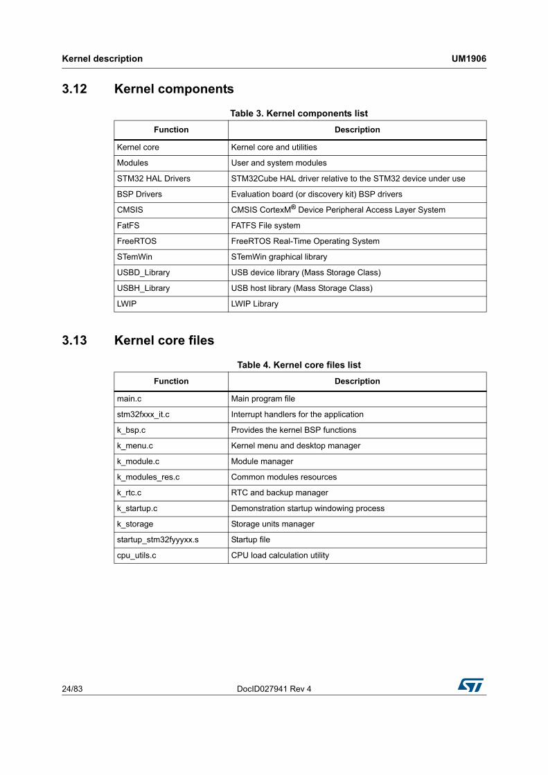
3.12 Kernel components
3.13 Kernel core files
Table 3. Kernel components list
Function Description
Kernel core Kernel core and utilities
Modules User and system modules
STM32 HAL Drivers STM32Cube HAL driver relative to the STM32 device under use
BSP Drivers Evaluation board (or discovery kit) BSP drivers
CMSIS CMSIS CortexM® Device Peripheral Access Layer System
FatFS FATFS File system
FreeRTOS FreeRTOS Real-Time Operating System
STemWin STemWin graphical library
USBD_Library USB device library (Mass Storage Class)
USBH_Library USB host library (Mass Storage Class)
LWIP LWIP Library
Table 4. Kernel core files list
Function Description
main.c Main program file
stm32fxxx_it.c Interrupt handlers for the application
k_bsp.c Provides the kernel BSP functions
k_menu.c Kernel menu and desktop manager
k_module.c Module manager
k_modules_res.c Common modules resources
k_rtc.c RTC and backup manager
k_startup.c Demonstration startup windowing process
k_storage Storage units manager
startup_stm32fyyyxx.s Startup file
cpu_utils.c CPU load calculation utility
DocID027941 Rev 4 25/83
UM1906 Kernel description
82
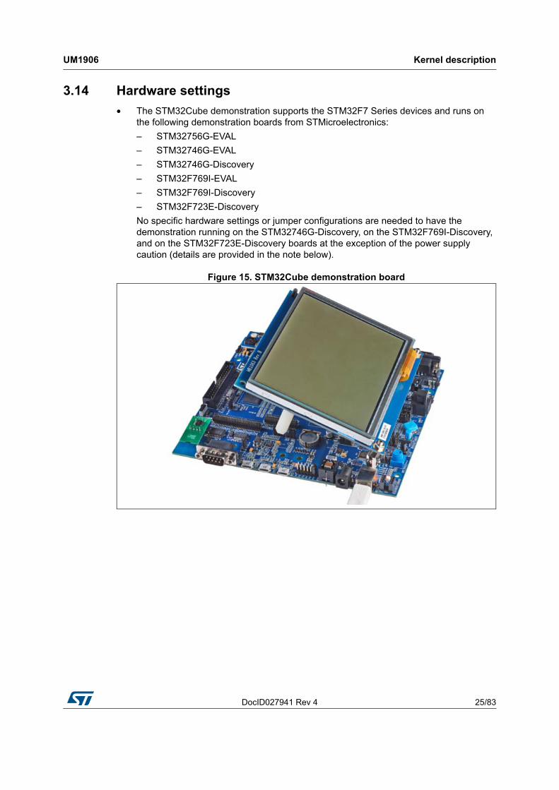
3.14 Hardware settings
• The STM32Cube demonstration supports the STM32F7 Series devices and runs on the following demonstration boards from STMicroelectronics:
– STM32756G-EVAL
– STM32746G-EVAL
– STM32746G-Discovery
– STM32F769I-EVAL
– STM32F769I-Discovery
– STM32F723E-Discovery
No specific hardware settings or jumper configurations are needed to have the demonstration running on the STM32746G-Discovery, on the STM32F769I-Discovery, and on the STM32F723E-Discovery boards at the exception of the power supply caution (details are provided in the note below).
Figure 15. STM32Cube demonstration board
Kernel description UM1906
26/83 DocID027941 Rev 4
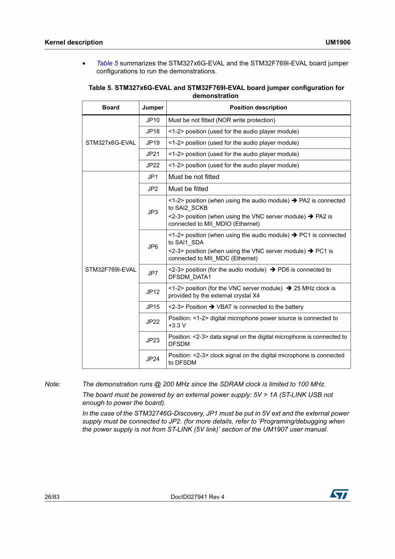
• Table 5 summarizes the STM327x6G-EVAL and the STM32F769I-EVAL board jumper configurations to run the demonstrations.
Note: The demonstration runs @ 200 MHz since the SDRAM clock is limited to 100 MHz.
The board must be powered by an external power supply: 5V > 1A (ST-LINK USB not enough to power the board).
In the case of the STM32746G-Discovery, JP1 must be put in 5V ext and the external power supply must be connected to JP2. (for more details, refer to ‘Programing/debugging when the power supply is not from ST-LINK (5V link)’ section of the UM1907 user manual.
Table 5. STM327x6G-EVAL and STM32F769I-EVAL board jumper configuration fordemonstration
Board Jumper Position description
STM327x6G-EVAL
JP10 Must be not fitted (NOR write protection)
JP18 <1-2> position (used for the audio player module)
JP19 <1-2> position (used for the audio player module)
JP21 <1-2> position (used for the audio player module)
JP22 <1-2> position (used for the audio player module)
STM32F769I-EVAL
JP1 Must be not fitted
JP2 Must be fitted
JP3
<1-2> position (when using the audio module) PA2 is connected to SAI2_SCKB
<2-3> position (when using the VNC server module) PA2 is connected to MII_MDIO (Ethernet)
JP6
<1-2> position (when using the audio module) PC1 is connected to SAI1_SDA
<2-3> position (when using the VNC server module) PC1 is connected to MII_MDC (Ethernet)
JP7<2-3> position (for the audio module) PD6 is connected to DFSDM_DATA1
JP12<1-2> position (for the VNC server module) 25 MHz clock is provided by the external crystal X4
JP15 <2-3> Position VBAT is connected to the battery
JP22Position: <1-2> digital microphone power source is connected to +3.3 V
JP23Position: <2-3> data signal on the digital microphone is connected to DFSDM
JP24Position: <2-3> clock signal on the digital microphone is connected to DFSDM

DocID027941 Rev 4 27/83
UM1906 Creating a new module
82
4 Creating a new module
A module is composed of two main parts:
• Graphical aspect: the main window frame and module controls
• Functionalities: the module functions and the internal processes
4.1 Creating the graphical aspect
The graphical aspect consists of the main frame window in addition to the set of the visual elements and controls (buttons, check boxes, progress bars…) used to control and monitor the module functionalities.
The demonstration package includes the GUI builder (Figure 16), a useful PC application used to easily and quickly create the module frame window and all its components.
Figure 16. GUI builder overview
The GUI builder needs only a few minutes to totally design the module appearances using "drag and drop" commands and then to generate the source code file to be included into the application.
The file generated is composed of the following main parts:
• A resource table: it is a table of type GUI_WIDGET_CREATE_INFO, which specifies all the widgets to be included in the dialog and also their respective positions and sizes.
• A dialog callback routine: described more in detail in Section 3.3 (it is referred to as “main module callback routine”).

Creating a new module UM1906
28/83 DocID027941 Rev 4
4.2 Graphics customization
After the basic module graphical appearance is created, it is then possible to customize some graphical elements, such as the buttons, by replacing the standard aspect by the user defined image. To do this, a new element drawing callback should be created and used instead of the original one.
Below an example of a custom callback for the play button:
On the code portion above, the _OnPaint_play routine contains just the new button drawing command.
Note that the new callback should be associated to the graphical element at the moment of its creation, as shown below:
Figure 17. Graphics customization
DocID027941 Rev 4 29/83
UM1906 Creating a new module
82
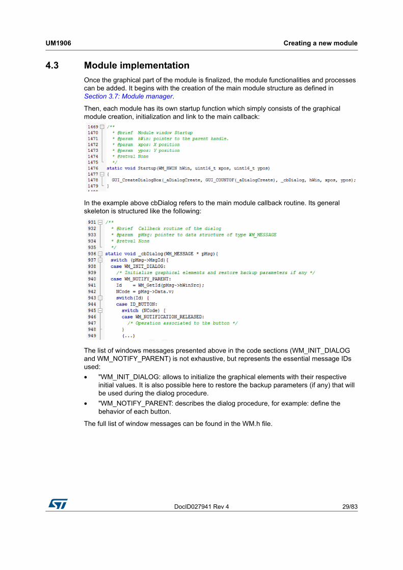
4.3 Module implementation
Once the graphical part of the module is finalized, the module functionalities and processes can be added. It begins with the creation of the main module structure as defined in Section 3.7: Module manager.
Then, each module has its own startup function which simply consists of the graphical module creation, initialization and link to the main callback:
In the example above cbDialog refers to the main module callback routine. Its general skeleton is structured like the following:
The list of windows messages presented above in the code sections (WM_INIT_DIALOG and WM_NOTIFY_PARENT) is not exhaustive, but represents the essential message IDs used:
• "WM_INIT_DIALOG: allows to initialize the graphical elements with their respective initial values. It is also possible here to restore the backup parameters (if any) that will be used during the dialog procedure.
• "WM_NOTIFY_PARENT: describes the dialog procedure, for example: define the behavior of each button.
The full list of window messages can be found in the WM.h file.
Creating a new module UM1906
30/83 DocID027941 Rev 4
4.4 Adding a module to the main desktop
Once the module appearance and functionality are defined and created, the module still needs to be added to the main desktop view. This is done by adding the module to the list (structure) of menu items: module_prop[ ], defined into k_module.h.
To do this, k_ModuleAdd() function must be called just after the module initialization into the main.c file.
Note that the maximum modules number in the demonstration package is limited to 15; this value can be changed by updating MAX_MODULES_NUM defined into k_module.c.
DocID027941 Rev 4 31/83
UM1906 Demonstration customization and configuration
82
5 Demonstration customization and configuration
5.1 LCD configuration
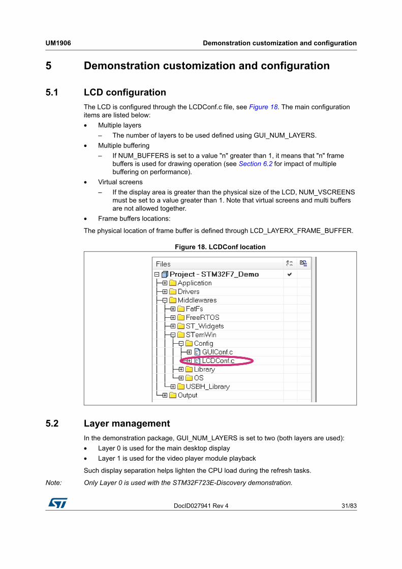
The LCD is configured through the LCDConf.c file, see Figure 18. The main configuration items are listed below:
• Multiple layers
– The number of layers to be used defined using GUI_NUM_LAYERS.
• Multiple buffering
– If NUM_BUFFERS is set to a value "n" greater than 1, it means that "n" frame buffers is used for drawing operation (see Section 6.2 for impact of multiple buffering on performance).
• Virtual screens
– If the display area is greater than the physical size of the LCD, NUM_VSCREENS must be set to a value greater than 1. Note that virtual screens and multi buffers are not allowed together.
• Frame buffers locations:
The physical location of frame buffer is defined through LCD_LAYERX_FRAME_BUFFER.
Figure 18. LCDConf location
5.2 Layer management
In the demonstration package, GUI_NUM_LAYERS is set to two (both layers are used):
• Layer 0 is used for the main desktop display
• Layer 1 is used for the video player module playback
Such display separation helps lighten the CPU load during the refresh tasks.
Note: Only Layer 0 is used with the STM32F723E-Discovery demonstration.

Demonstration customization and configuration UM1906
32/83 DocID027941 Rev 4
5.3 BSP customization
5.3.1 SDRAM configuration
The SDRAM capacity is 1 Mbyte x 32 bit x 4 banks.
The BSP SDRAM driver offers a set of functions to initialize, read/write in polling or DMA mode (see Figure 19).
Figure 19. SDRAM initialization
The SDRAM external memory must be initialized before the GUI initialization to allow its use as a LCD layer frame buffer.
Table 6. LCD frame buffer locations
Layer Address
LCD Layer0 0xC0000000
LCD Layer1 0xC0400000
DocID027941 Rev 4 33/83
UM1906 Demonstration customization and configuration
82
5.3.2 Touch screen configuration
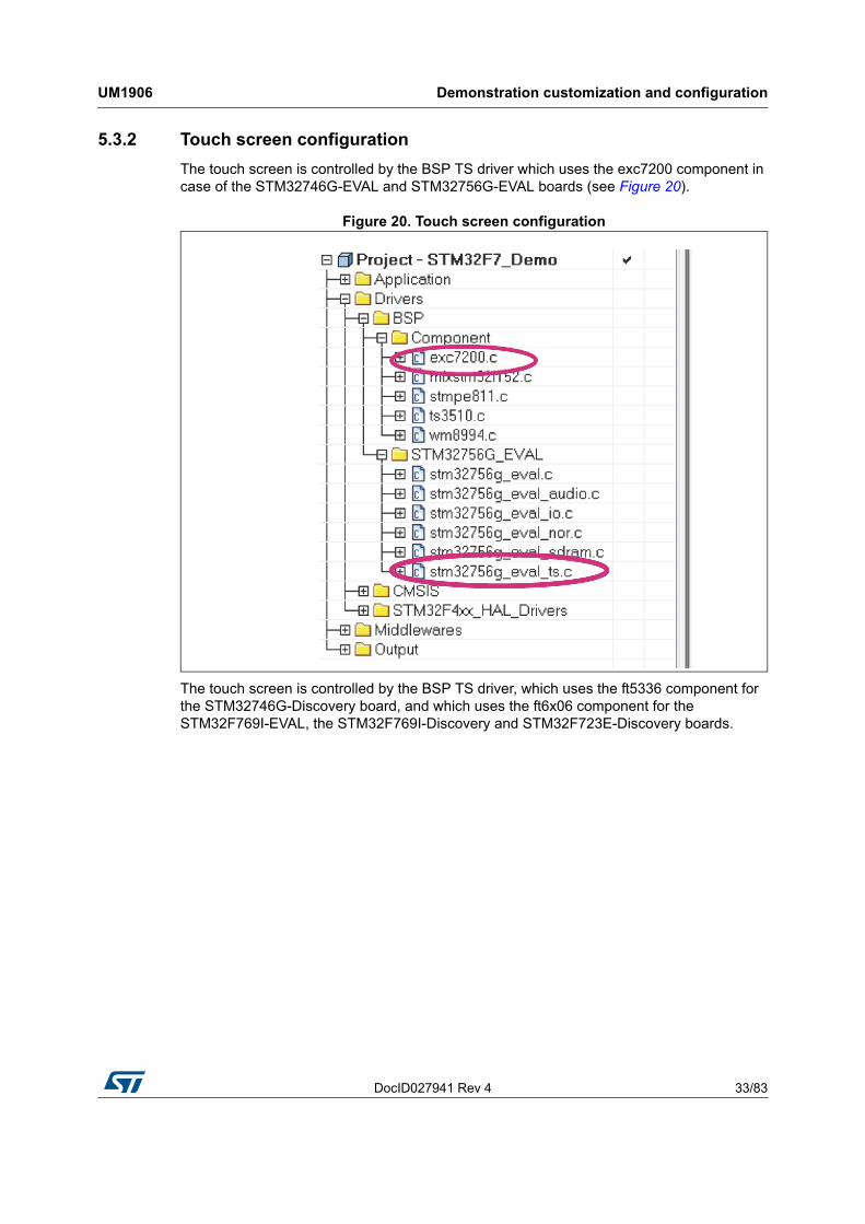
The touch screen is controlled by the BSP TS driver which uses the exc7200 component in case of the STM32746G-EVAL and STM32756G-EVAL boards (see Figure 20).
Figure 20. Touch screen configuration
The touch screen is controlled by the BSP TS driver, which uses the ft5336 component for the STM32746G-Discovery board, and which uses the ft6x06 component for the STM32F769I-EVAL, the STM32F769I-Discovery and STM32F723E-Discovery boards.
Demonstration customization and configuration UM1906
34/83 DocID027941 Rev 4
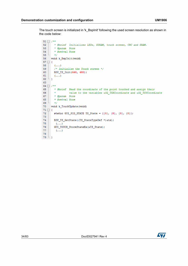
The touch screen is initialized in 'k_BspInit' following the used screen resolution as shown in the code below:

DocID027941 Rev 4 35/83
UM1906 Performance
82
6 Performance
6.1 CPU cache
The STM32F7 demonstration benefits from the cortex-M7 performance.
Table 7 summarizes the instruction and data caches for each device in STM32F7 Series.
Figure 21 shows the overall system architecture of the STM32F7 Series devices as well as the bus matrix connections.
Figure 21. STM32F7 Series system architecture
1. I/D cache size:- For the STM32F74xxx and STM32F75xxx devices: 4 Kbytes.
- For the STM32F76xxx and STM32F77xxx devices: 16 Kbytes
- For the STM32F72xxx and STM32F73xxx devices: 8 Kbytes.
Table 7. Memory dedicated for I/D cache for each device family
Devices Instruction cache Data cache
STM32F7x9I 16 Kbytes 16 Kbytes
STM32F7x6G 4 Kbytes 4 Kbytes
STM32F72xE 8 Kbytes 8 Kbytes
Performance UM1906
36/83 DocID027941 Rev 4
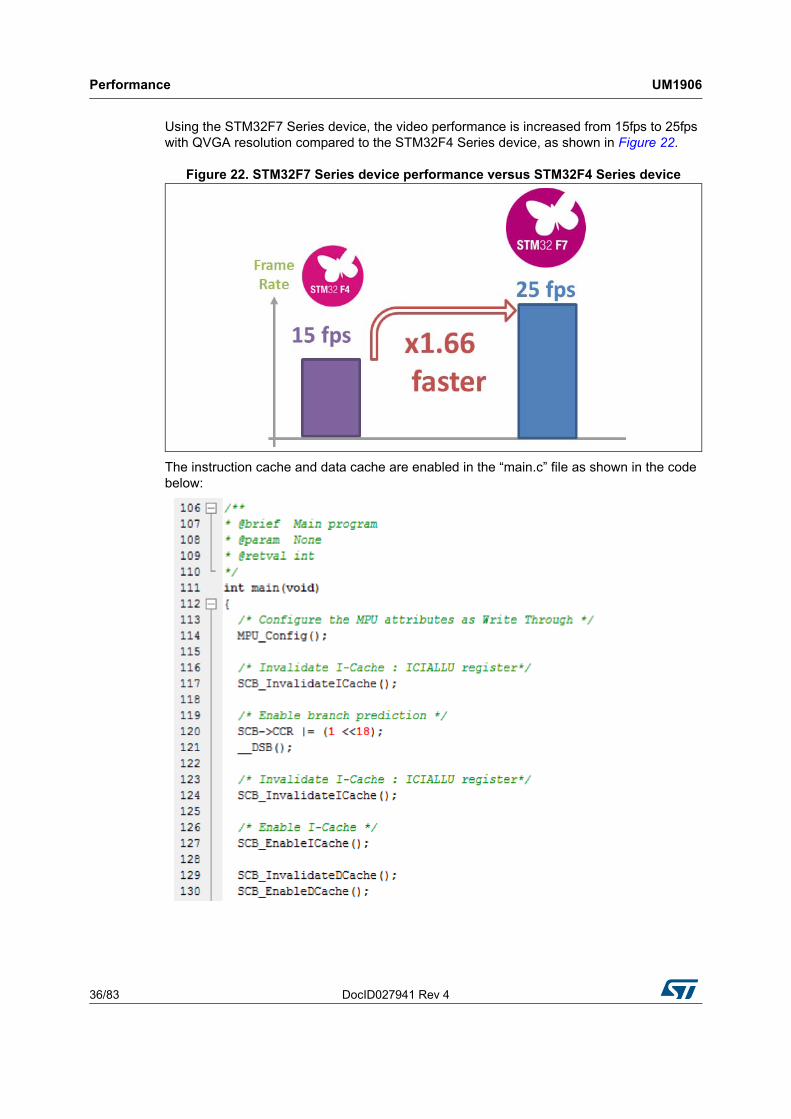
Using the STM32F7 Series device, the video performance is increased from 15fps to 25fps with QVGA resolution compared to the STM32F4 Series device, as shown in Figure 22.
Figure 22. STM32F7 Series device performance versus STM32F4 Series device
The instruction cache and data cache are enabled in the “main.c” file as shown in the code below:
DocID027941 Rev 4 37/83
UM1906 Performance
82
6.2 Multi buffering features
Note: This section is not applicable for the STM32F723E-Discovery demonstrations.
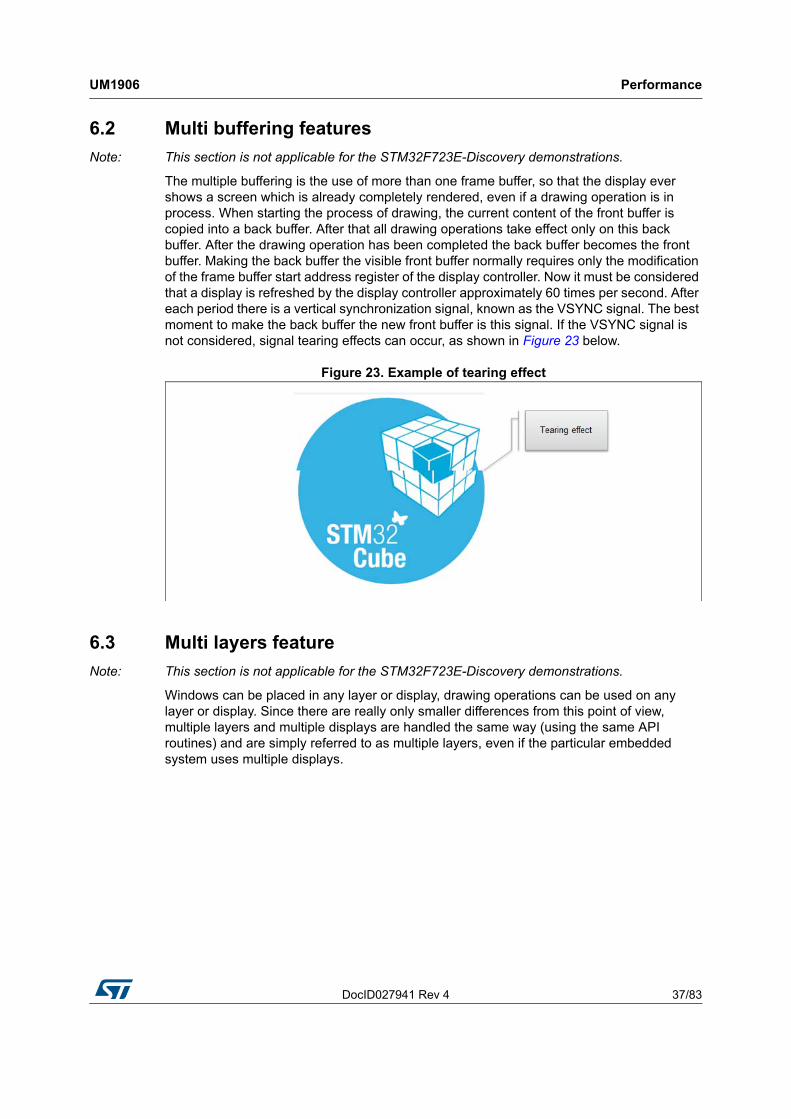
The multiple buffering is the use of more than one frame buffer, so that the display ever shows a screen which is already completely rendered, even if a drawing operation is in process. When starting the process of drawing, the current content of the front buffer is copied into a back buffer. After that all drawing operations take effect only on this back buffer. After the drawing operation has been completed the back buffer becomes the front buffer. Making the back buffer the visible front buffer normally requires only the modification of the frame buffer start address register of the display controller. Now it must be considered that a display is refreshed by the display controller approximately 60 times per second. After each period there is a vertical synchronization signal, known as the VSYNC signal. The best moment to make the back buffer the new front buffer is this signal. If the VSYNC signal is not considered, signal tearing effects can occur, as shown in Figure 23 below.
Figure 23. Example of tearing effect
6.3 Multi layers feature
Note: This section is not applicable for the STM32F723E-Discovery demonstrations.
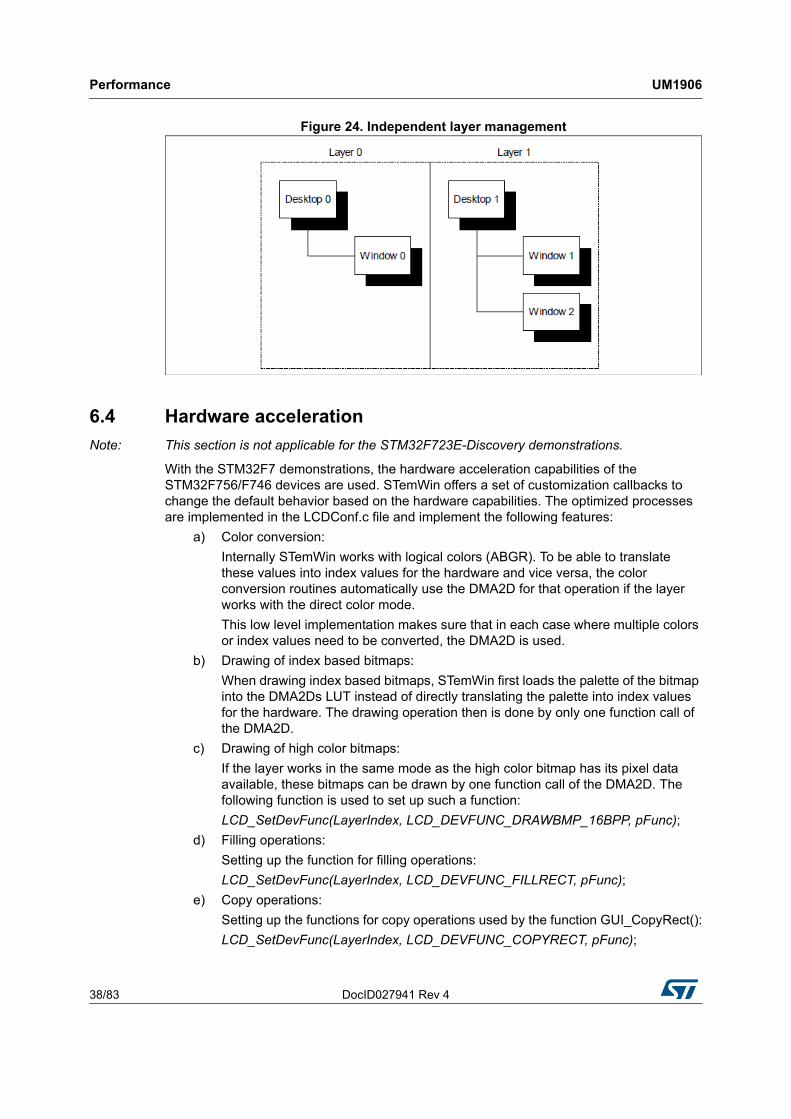
Windows can be placed in any layer or display, drawing operations can be used on any layer or display. Since there are really only smaller differences from this point of view, multiple layers and multiple displays are handled the same way (using the same API routines) and are simply referred to as multiple layers, even if the particular embedded system uses multiple displays.
Performance UM1906
38/83 DocID027941 Rev 4
Figure 24. Independent layer management
6.4 Hardware acceleration
Note: This section is not applicable for the STM32F723E-Discovery demonstrations.
With the STM32F7 demonstrations, the hardware acceleration capabilities of the STM32F756/F746 devices are used. STemWin offers a set of customization callbacks to change the default behavior based on the hardware capabilities. The optimized processes are implemented in the LCDConf.c file and implement the following features:
a) Color conversion:
Internally STemWin works with logical colors (ABGR). To be able to translate these values into index values for the hardware and vice versa, the color conversion routines automatically use the DMA2D for that operation if the layer works with the direct color mode.
This low level implementation makes sure that in each case where multiple colors or index values need to be converted, the DMA2D is used.
b) Drawing of index based bitmaps:
When drawing index based bitmaps, STemWin first loads the palette of the bitmap into the DMA2Ds LUT instead of directly translating the palette into index values for the hardware. The drawing operation then is done by only one function call of the DMA2D.
c) Drawing of high color bitmaps:
If the layer works in the same mode as the high color bitmap has its pixel data available, these bitmaps can be drawn by one function call of the DMA2D. The following function is used to set up such a function:
LCD_SetDevFunc(LayerIndex, LCD_DEVFUNC_DRAWBMP_16BPP, pFunc);
d) Filling operations:
Setting up the function for filling operations:
LCD_SetDevFunc(LayerIndex, LCD_DEVFUNC_FILLRECT, pFunc);
e) Copy operations:
Setting up the functions for copy operations used by the function GUI_CopyRect():
LCD_SetDevFunc(LayerIndex, LCD_DEVFUNC_COPYRECT, pFunc);
DocID027941 Rev 4 39/83
UM1906 Performance
82
f) Copy buffers:
Setting up the function for transferring the front to the back buffer when using multiple buffers:
LCD_SetDevFunc(LayerIndex, LCD_DEVFUNC_COPYBUFFER, pFunc);
g) Fading operations:
Setting up the function for mixing up a background and a foreground buffer used for fading memory devices:
GUI_SetFuncMixColorsBulk(pFunc);
h) General alpha blending:
The following function replaces the function which is used internally for alpha blending operations during an image drawing (PNG or true color bitmaps) or semitransparent memory devices:
GUI_SetFuncAlphaBlending(pFunc);
i) Drawing antialiased fonts:
Setting up the function for mixing single foreground and background colors used when drawing a transparent ant aliased text:
GUI_SetFuncMixColors(pFunc).
6.5 Hardware JPEG Decoding
The STM32F7 Series device is now supporting the new feature of the JPEG codec.
The JPEG codec provides an fast and simple hardware compressor and decompressor of JPEG images with the full management of JPEG headers.
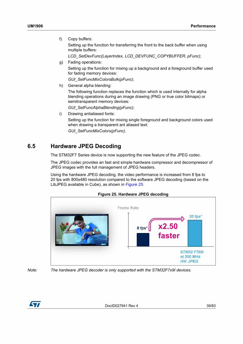
Using the hardware JPEG decoding, the video performance is increased from 8 fps to 20 fps with 800x480 resolution compared to the software JPEG decoding (based on the LibJPEG available in Cube), as shown in Figure 25.
Figure 25. Hardware JPEG decoding
Note: The hardware JPEG decoder is only supported with the STM32F7x9I devices.

Footprint UM1906
40/83 DocID027941 Rev 4
7 Footprint
The purpose of the following sections is to provide the memory requirements for all the demonstration modules, including the jpeg decoder and STemWin's main GUI components. The aim is to have an estimation of memory requirement in case of suppression or addition of a module or feature.
The footprint data are provided for the following environment:
• Tool chain: IAR 7.40.1
• Optimization: high size
• Boards: STM327x6G-EVAL, STM32746G-Discovery
Table 8 shows the code memory, data memory and the constant memory used for each kernel file.
Table 8. Module footprint
File Code [byte] Data [byte] Const [byte]
Audio 9500 29012 422328(1)
1. Some resources saved in NOR Flash memory for the STM327x6G_EVAL demonstration. For the STM32746G-Discovery all resources are stored in QSPI memory.
Audio recorder 2156 690 334336
VNC server 3452 431 + 15560(2)
2. 15560 size of shared bytes.
457884
Video 5276 3717 1754819(3)
3. All resources are stored in NOR Flash memory for the STM327x6G-EVAL demonstration. For the STM32746G-Discovery, All resources are stored in QSPI memory.
Home alarm 3340 56 5772536(3)
Garden control 1088 44 929905(3)
Games 3852 1936 245875(3)
System info 1252 340 1476719(3)

DocID027941 Rev 4 41/83
UM1906 Footprint
82
7.1 STemWin features resources
7.1.1 JPEG decoder
The JPEG decompression uses approximately 33 Kbytes of RAM for the decompression independently of the image size and a size dependent amount of byte. The RAM requirement can be calculated as follows:
Approximate RAM requirement = X-Size of image * 80 bytes + 33 Kbytes
The memory required for the decompression is allocated dynamically by the STemWin memory management system. After drawing the JPEG image the complete RAM will be released.
7.1.2 GUI Components
The operation area of STemWin varies widely, depending primarily on the application and features used. In the following sections, the memory requirements of various modules are listed, as well as the memory requirements of example applications.
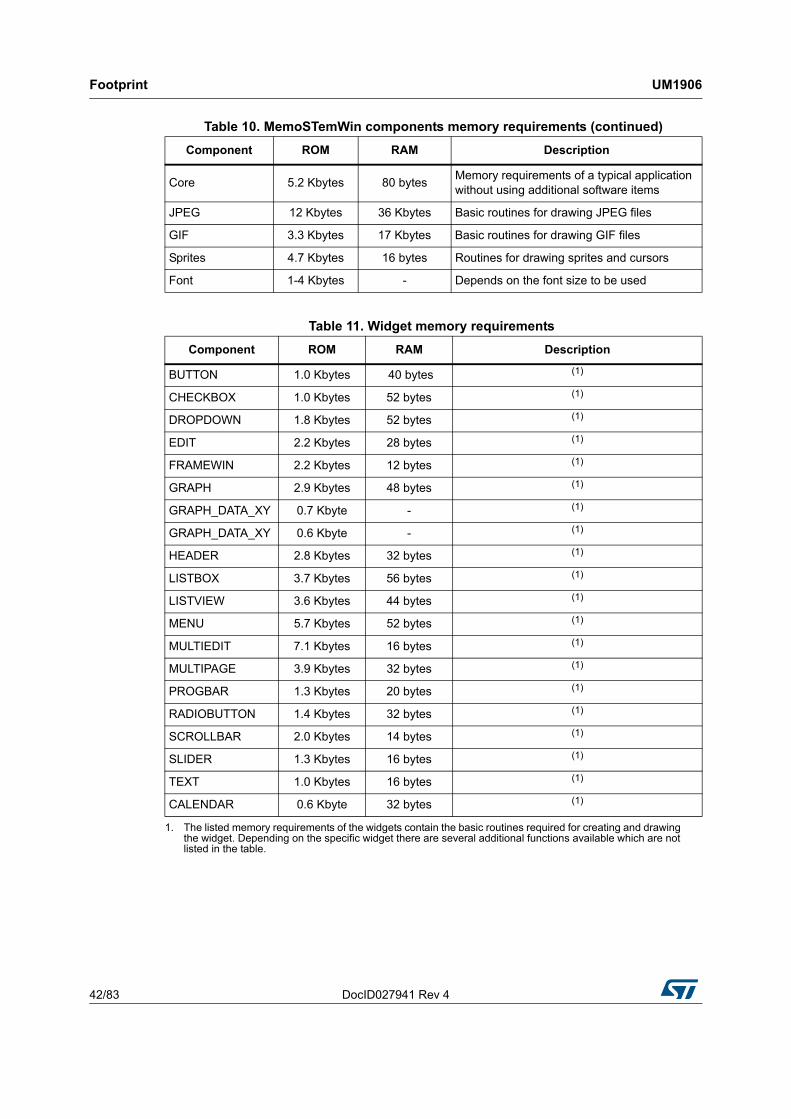
Table 10 shows the memory requirements of the main components of STemWin. These values depend a lot on the compiler options, the compiler version and the used CPU. Note that the listed values are the requirements of the basic functions of each module.
Table 9. RAM requirements for some JPEG resolutions
Resolution RAM usage [Kbyte] RAM usage, size dependent [Kbyte]
160x120 45.5 12.5
320x340 58.0 25.0
480x272 70.5 37.5
640x480 83.0 50.0
Table 10. MemoSTemWin components memory requirements
Component ROM RAM Description
Windows Manager 6.2 Kbytes 2.5 KbytesAdditional memory requirements of basic application when using the Windows Manager
Memory Devices 4.7 Kbytes 7 KbytesAdditional memory requirements of basic application when using memory devices
Antialiasing 4.5 Kbytes 2 * LCD_XSIZEAdditional memory requirements for the antialiasing software item
Driver 2-8 Kbytes 20 bytes
The memory requirements of the driver depend on the configured driver and whether a data cache is used or not.
With a data cache, the driver requires more RAM
Multilayer 2-8 Kbytes -
If working with a multi layer or a multi display configuration, additional memory is required for each additional layer, because each requires its own driver
Footprint UM1906
42/83 DocID027941 Rev 4
Core 5.2 Kbytes 80 bytesMemory requirements of a typical application without using additional software items
JPEG 12 Kbytes 36 Kbytes Basic routines for drawing JPEG files
GIF 3.3 Kbytes 17 Kbytes Basic routines for drawing GIF files
Sprites 4.7 Kbytes 16 bytes Routines for drawing sprites and cursors
Font 1-4 Kbytes - Depends on the font size to be used
Table 11. Widget memory requirements
Component ROM RAM Description
BUTTON 1.0 Kbytes 40 bytes (1)
1. The listed memory requirements of the widgets contain the basic routines required for creating and drawing the widget. Depending on the specific widget there are several additional functions available which are not listed in the table.
CHECKBOX 1.0 Kbytes 52 bytes (1)
DROPDOWN 1.8 Kbytes 52 bytes (1)
EDIT 2.2 Kbytes 28 bytes (1)
FRAMEWIN 2.2 Kbytes 12 bytes (1)
GRAPH 2.9 Kbytes 48 bytes (1)
GRAPH_DATA_XY 0.7 Kbyte - (1)
GRAPH_DATA_XY 0.6 Kbyte - (1)
HEADER 2.8 Kbytes 32 bytes (1)
LISTBOX 3.7 Kbytes 56 bytes (1)
LISTVIEW 3.6 Kbytes 44 bytes (1)
MENU 5.7 Kbytes 52 bytes (1)
MULTIEDIT 7.1 Kbytes 16 bytes (1)
MULTIPAGE 3.9 Kbytes 32 bytes (1)
PROGBAR 1.3 Kbytes 20 bytes (1)
RADIOBUTTON 1.4 Kbytes 32 bytes (1)
SCROLLBAR 2.0 Kbytes 14 bytes (1)
SLIDER 1.3 Kbytes 16 bytes (1)
TEXT 1.0 Kbytes 16 bytes (1)
CALENDAR 0.6 Kbyte 32 bytes (1)
Table 10. MemoSTemWin components memory requirements (continued)
Component ROM RAM Description
DocID027941 Rev 4 43/83
UM1906 Demonstration functional description (part of STM32F7xxx boards)
82
8 Demonstration functional description (part of STM32F7xxx boards)
This section is applicable for the STM32756G-EVAL, the STM32746G-Discovery, the STM32F769I-EVAL and the STM32F769I-Discovery boards.
8.1 Audio player
Overview
The audio player module provides a complete audio solution based on the STM32F7xxx device and delivers a high-quality music experience. It supports playing music in WAV format but may be extended to support other compressed formats such as MP3 and WMA audio formats.
Features
• Audio format: WAV format without compression with 8 k to 96 k sampling
• Embeds an equalizer and loudness control
• Performance: MCU load < 5%
• Audio files stored in USB Disk Flash (USB High Speed)
• Supports background mode feature
• Only 8 Kbytes of RAM required for audio processing
• MP3 format not supported but can be easily added (separate demonstration flavor).
Demonstration functional description (part of STM32F7xxx boards) UM1906
44/83 DocID027941 Rev 4
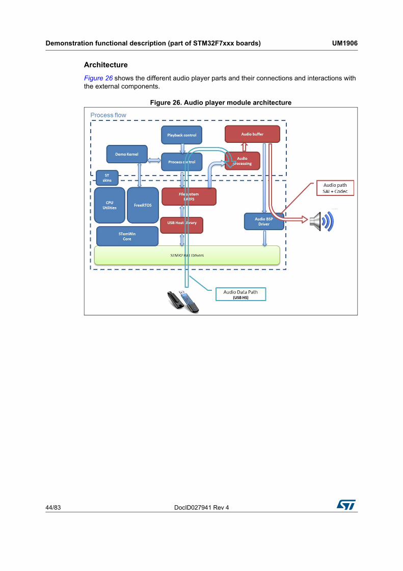
Architecture
Figure 26 shows the different audio player parts and their connections and interactions with the external components.
Figure 26. Audio player module architecture

DocID027941 Rev 4 45/83
UM1906 Demonstration functional description (part of STM32F7xxx boards)
82
Performance
Figure 27 shows the used performance mechanisms in audio process and audio player.
Figure 27. Audio player process
Process description
The audio player initialization is done in the startup step. In this step all the audio player states, the speaker and the volume value are initialized and only when the play button in the audio player interface is pressed to start the process.
• Start the audio player module from the main desktop menu as shown in Figure 28 below:
Figure 28. Audio player module startup
Demonstration functional description (part of STM32F7xxx boards) UM1906
46/83 DocID027941 Rev 4
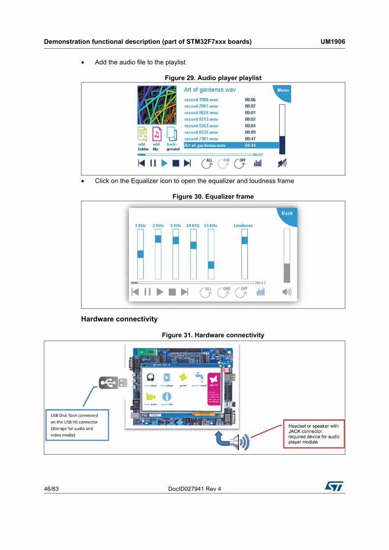
• Add the audio file to the playlist
Figure 29. Audio player playlist
• Click on the Equalizer icon to open the equalizer and loudness frame
Figure 30. Equalizer frame
Hardware connectivity
Figure 31. Hardware connectivity
DocID027941 Rev 4 47/83
UM1906 Demonstration functional description (part of STM32F7xxx boards)
82
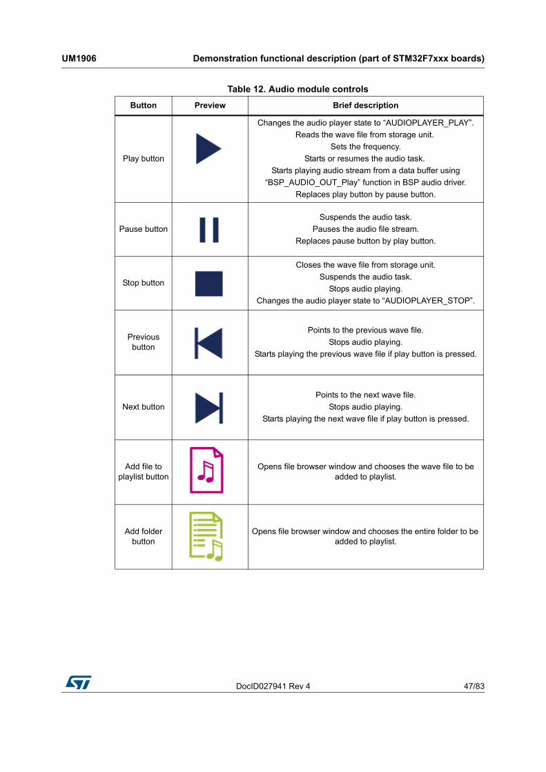
Table 12. Audio module controls
Button Preview Brief description
Play button
Changes the audio player state to “AUDIOPLAYER_PLAY”.
Reads the wave file from storage unit.
Sets the frequency.
Starts or resumes the audio task.
Starts playing audio stream from a data buffer using
“BSP_AUDIO_OUT_Play” function in BSP audio driver.
Replaces play button by pause button.
Pause button
Suspends the audio task.
Pauses the audio file stream.
Replaces pause button by play button.
Stop button
Closes the wave file from storage unit.
Suspends the audio task.
Stops audio playing.
Changes the audio player state to “AUDIOPLAYER_STOP”.
Previous button
Points to the previous wave file.
Stops audio playing.
Starts playing the previous wave file if play button is pressed.
Next button
Points to the next wave file.
Stops audio playing.
Starts playing the next wave file if play button is pressed.
Add file to playlist button
Opens file browser window and chooses the wave file to be added to playlist.
Add folder button
Opens file browser window and chooses the entire folder to be added to playlist.
Demonstration functional description (part of STM32F7xxx boards) UM1906
48/83 DocID027941 Rev 4
8.2 Audio recorder
Overview
The audio recorder module can be used to record audio frames in WAV format, save them in the storage unit and play them later.
Note: The audio recorder module is only applicable to the STM32746G-Discovery board.
Features
• Audio format: WAV format without compression with 16 k sampling stereo
• Performance: MCU Load < 5%
• Recorded files stored in USB Disk Flash (USB High Speed)
• Embeds quick audio player
• Only 8 Kbytes of RAM required for audio processing
• MP3 format NOT supported but can be easily added (separate demonstration flavor)
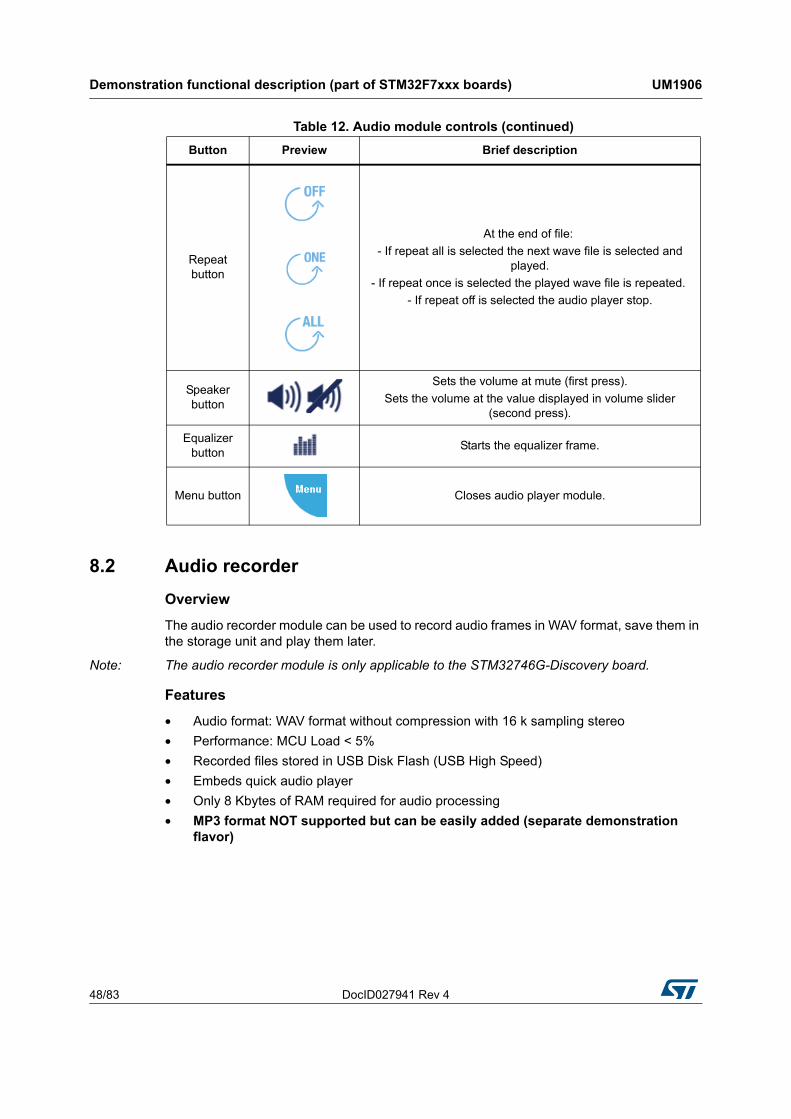
Repeat button
At the end of file:
- If repeat all is selected the next wave file is selected and played.
- If repeat once is selected the played wave file is repeated.
- If repeat off is selected the audio player stop.
Speaker button
Sets the volume at mute (first press).
Sets the volume at the value displayed in volume slider (second press).
Equalizer button
Starts the equalizer frame.
Menu button Closes audio player module.
Table 12. Audio module controls (continued)
Button Preview Brief description
DocID027941 Rev 4 49/83
UM1906 Demonstration functional description (part of STM32F7xxx boards)
82
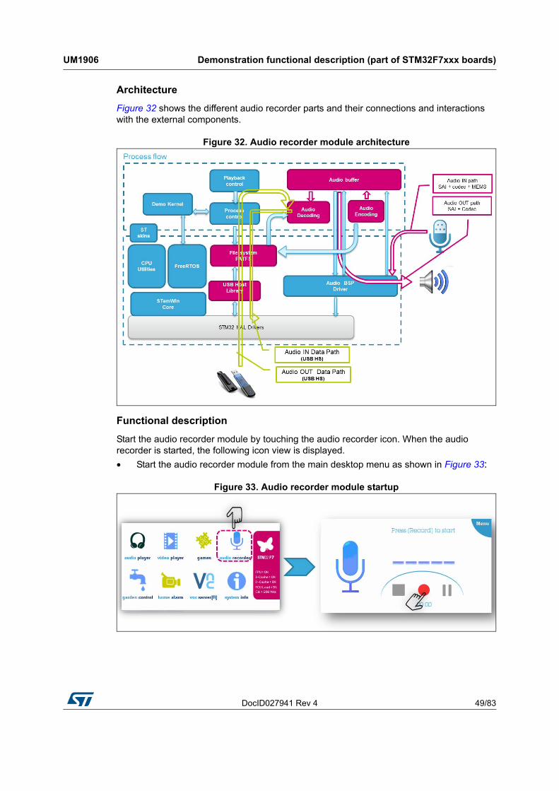
Architecture
Figure 32 shows the different audio recorder parts and their connections and interactions with the external components.
Figure 32. Audio recorder module architecture
Functional description
Start the audio recorder module by touching the audio recorder icon. When the audio recorder is started, the following icon view is displayed.
• Start the audio recorder module from the main desktop menu as shown in Figure 33:
Figure 33. Audio recorder module startup
Demonstration functional description (part of STM32F7xxx boards) UM1906
50/83 DocID027941 Rev 4
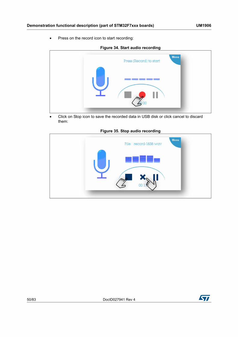
• Press on the record icon to start recording:
Figure 34. Start audio recording
• Click on Stop icon to save the recorded data in USB disk or click cancel to discard them:
Figure 35. Stop audio recording
DocID027941 Rev 4 51/83
UM1906 Demonstration functional description (part of STM32F7xxx boards)
82
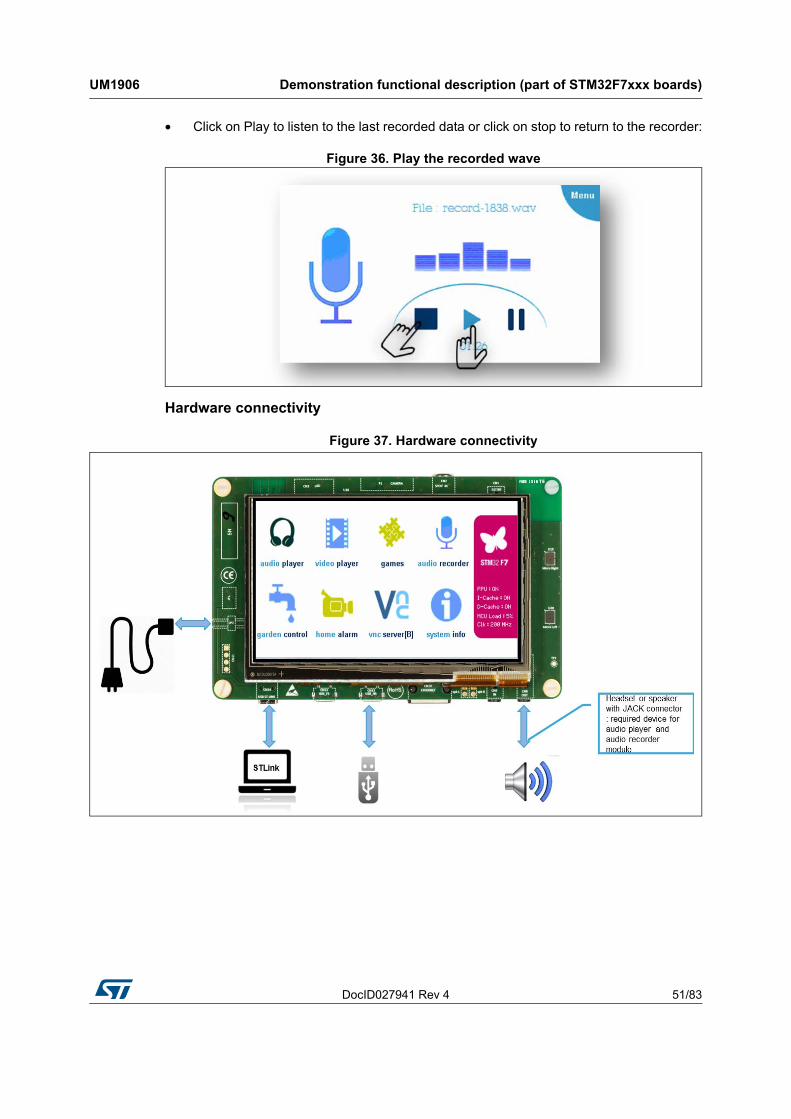
• Click on Play to listen to the last recorded data or click on stop to return to the recorder:
Figure 36. Play the recorded wave
Hardware connectivity
Figure 37. Hardware connectivity
Demonstration functional description (part of STM32F7xxx boards) UM1906
52/83 DocID027941 Rev 4
8.3 VNC server
Overview
The VNC server module allows controlling the demonstration from a remote machine. It is based on the TCP/IP LwIP stacks. The background mode is supported.
Note: The VNC server module is only applicable to the STM32746G-Discovery board.
Features
• Based on the TCP/IP LwIP stacks (socket)
• IP address assigned by DHCP
• Secured mode supported (DES Encryption)
• Performance: MCU Load < 2 % (standalone)
• Background mode support
• Requires less than ~200 - 300 ms to update the entire display.
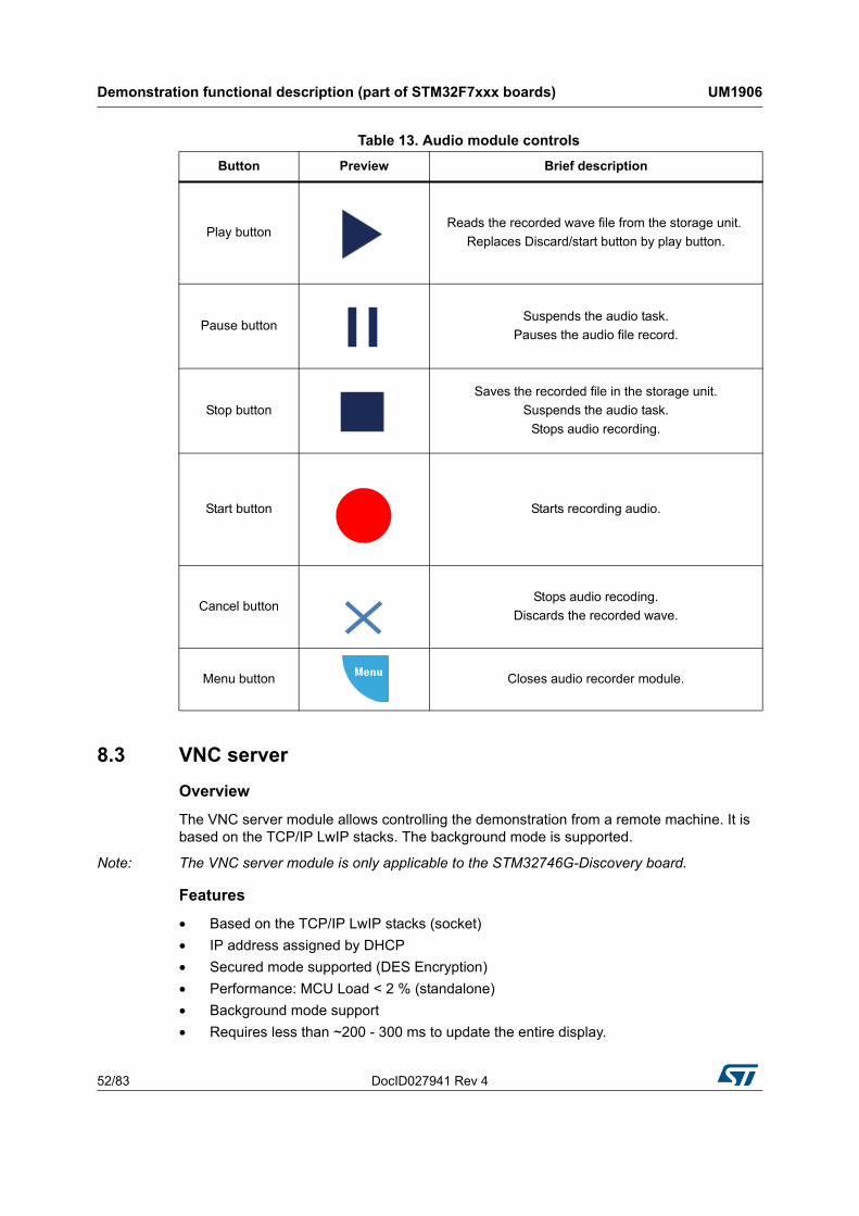
Table 13. Audio module controls
Button Preview Brief description
Play buttonReads the recorded wave file from the storage unit.
Replaces Discard/start button by play button.
Pause buttonSuspends the audio task.
Pauses the audio file record.
Stop button
Saves the recorded file in the storage unit.
Suspends the audio task.
Stops audio recording.
Start button Starts recording audio.
Cancel buttonStops audio recoding.
Discards the recorded wave.
Menu button Closes audio recorder module.
DocID027941 Rev 4 53/83
UM1906 Demonstration functional description (part of STM32F7xxx boards)
82
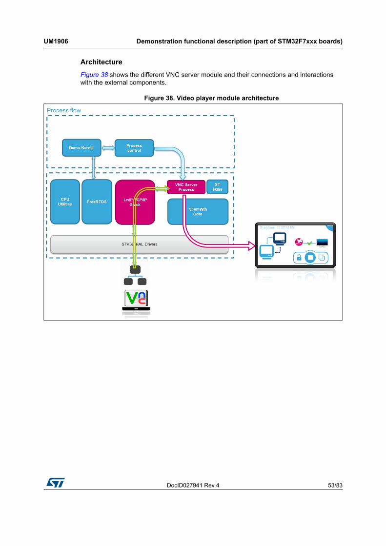
Architecture
Figure 38 shows the different VNC server module and their connections and interactions with the external components.
Figure 38. Video player module architecture
Demonstration functional description (part of STM32F7xxx boards) UM1906
54/83 DocID027941 Rev 4
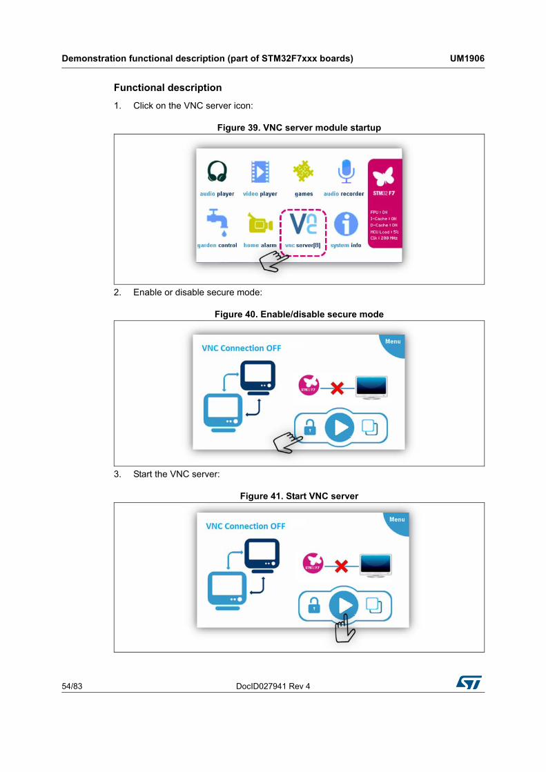
Functional description
1. Click on the VNC server icon:
Figure 39. VNC server module startup
2. Enable or disable secure mode:
Figure 40. Enable/disable secure mode
3. Start the VNC server:
Figure 41. Start VNC server
DocID027941 Rev 4 55/83
UM1906 Demonstration functional description (part of STM32F7xxx boards)
82
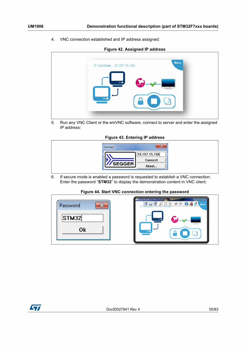
4. VNC connection established and IP address assigned:
Figure 42. Assigned IP address
5. Run any VNC Client or the emVNC software, connect to server and enter the assigned IP address:
Figure 43. Entering IP address
6. If secure mode is enabled a password is requested to establish a VNC connection. Enter the password “STM32” to display the demonstration content in VNC client:
Figure 44. Start VNC connection entering the password
Demonstration functional description (part of STM32F7xxx boards) UM1906
56/83 DocID027941 Rev 4
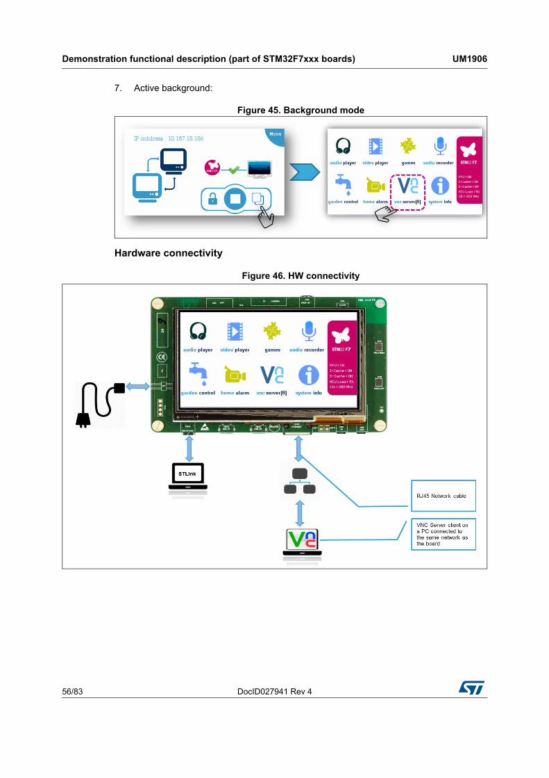
7. Active background:
Figure 45. Background mode
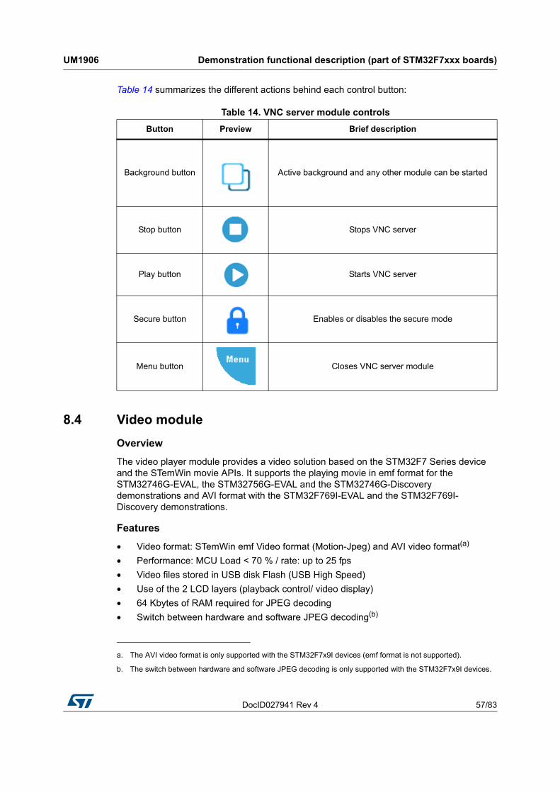
Hardware connectivity
Figure 46. HW connectivity
DocID027941 Rev 4 57/83
UM1906 Demonstration functional description (part of STM32F7xxx boards)
82
Table 14 summarizes the different actions behind each control button:
8.4 Video module
Overview
The video player module provides a video solution based on the STM32F7 Series device and the STemWin movie APIs. It supports the playing movie in emf format for the STM32746G-EVAL, the STM32756G-EVAL and the STM32746G-Discovery demonstrations and AVI format with the STM32F769I-EVAL and the STM32F769I-Discovery demonstrations.
Features
• Video format: STemWin emf Video format (Motion-Jpeg) and AVI video format(a)
• Performance: MCU Load < 70 % / rate: up to 25 fps
• Video files stored in USB disk Flash (USB High Speed)
• Use of the 2 LCD layers (playback control/ video display)
• 64 Kbytes of RAM required for JPEG decoding
• Switch between hardware and software JPEG decoding(b)
Table 14. VNC server module controls
Button Preview Brief description
Background button Active background and any other module can be started
Stop button Stops VNC server
Play button Starts VNC server
Secure button Enables or disables the secure mode
Menu button Closes VNC server module
a. The AVI video format is only supported with the STM32F7x9I devices (emf format is not supported).
b. The switch between hardware and software JPEG decoding is only supported with the STM32F7x9I devices.
Demonstration functional description (part of STM32F7xxx boards) UM1906
58/83 DocID027941 Rev 4
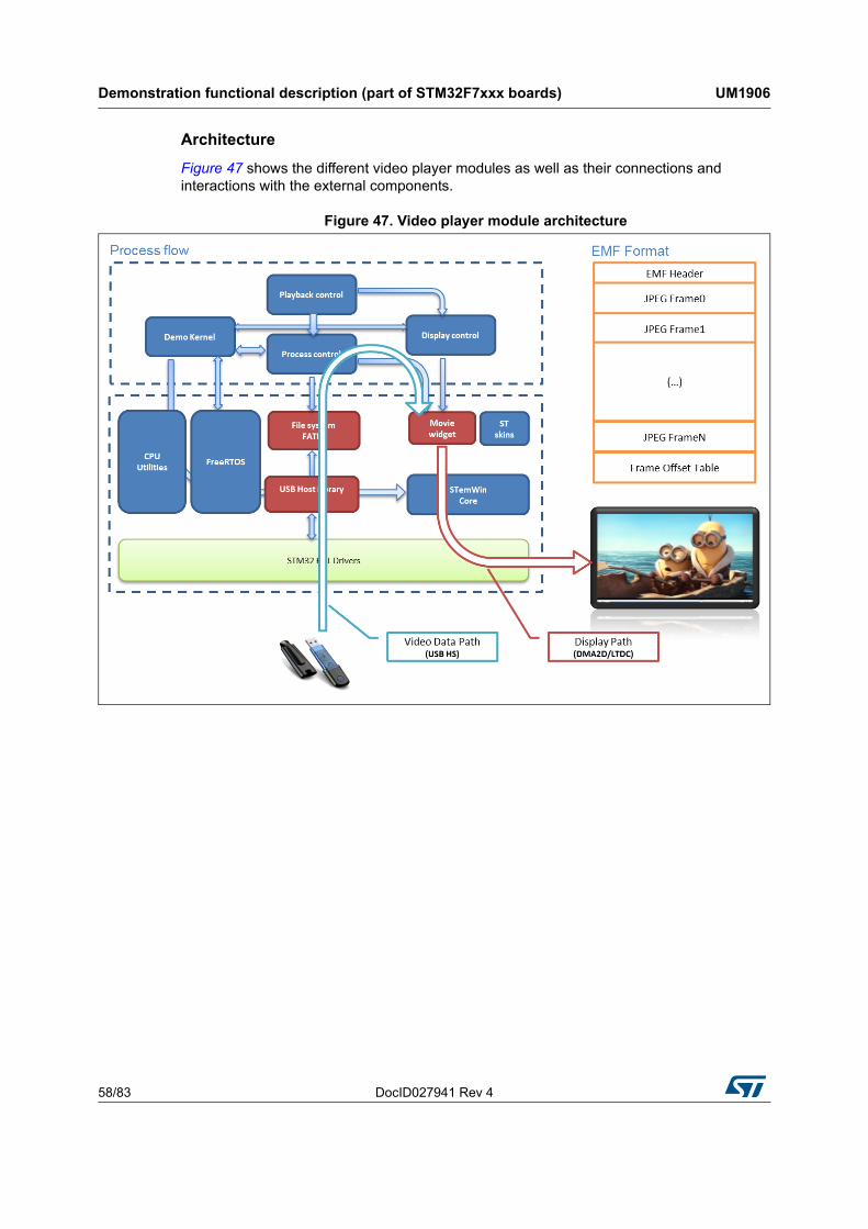
Architecture
Figure 47 shows the different video player modules as well as their connections and interactions with the external components.
Figure 47. Video player module architecture
DocID027941 Rev 4 59/83
UM1906 Demonstration functional description (part of STM32F7xxx boards)
82
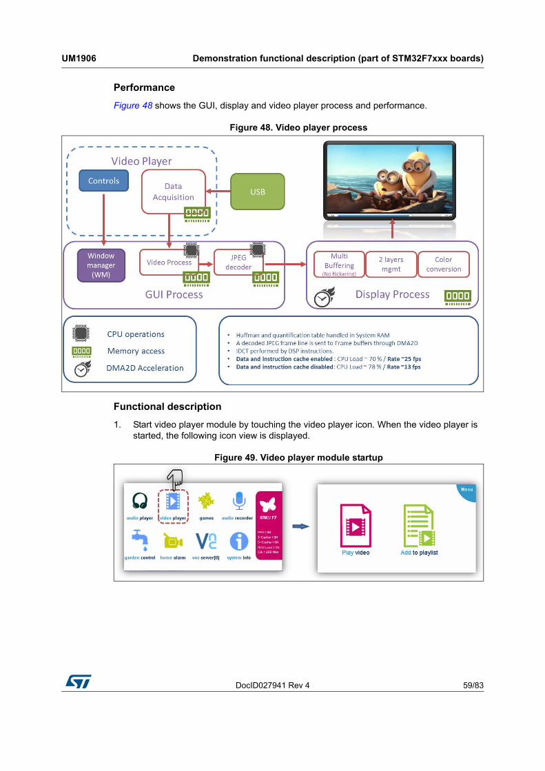
Performance
Figure 48 shows the GUI, display and video player process and performance.
Figure 48. Video player process
Functional description
1. Start video player module by touching the video player icon. When the video player is started, the following icon view is displayed.
Figure 49. Video player module startup
Demonstration functional description (part of STM32F7xxx boards) UM1906
60/83 DocID027941 Rev 4
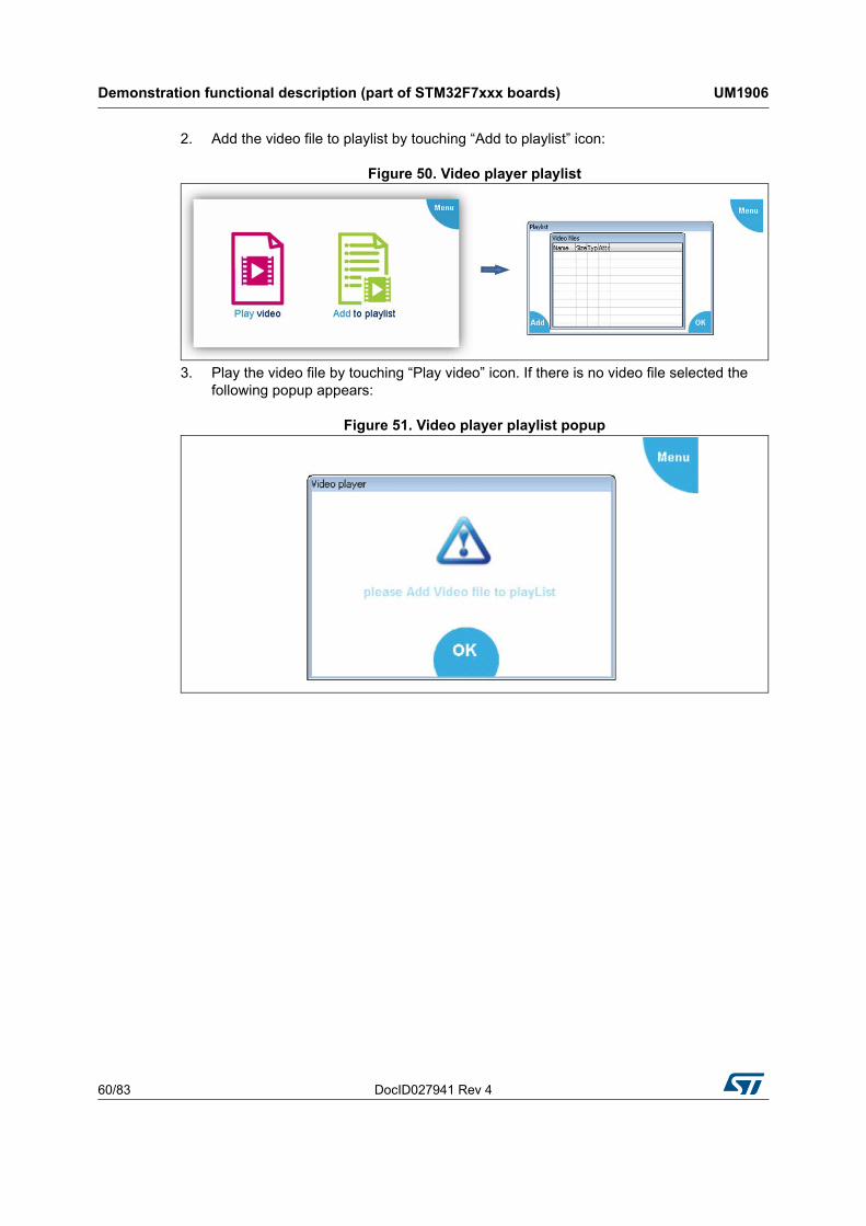
2. Add the video file to playlist by touching “Add to playlist” icon:
Figure 50. Video player playlist
3. Play the video file by touching “Play video” icon. If there is no video file selected the following popup appears:
Figure 51. Video player playlist popup
DocID027941 Rev 4 61/83
UM1906 Demonstration functional description (part of STM32F7xxx boards)
82
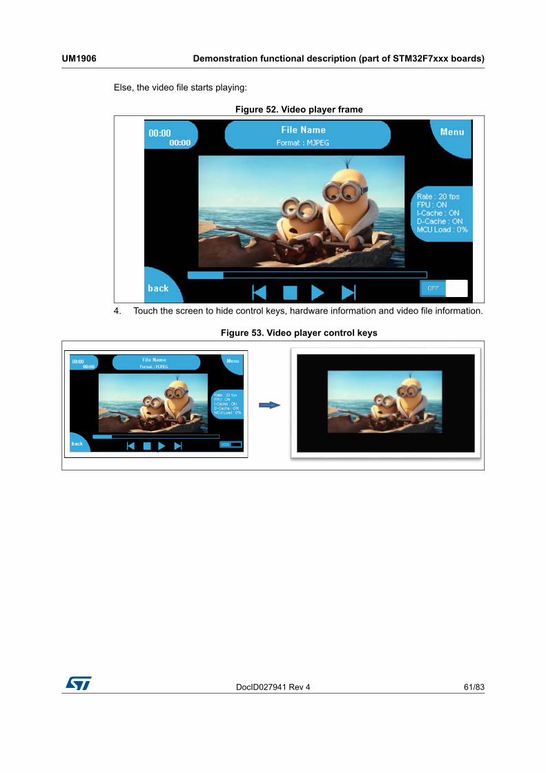
Else, the video file starts playing:
Figure 52. Video player frame
4. Touch the screen to hide control keys, hardware information and video file information.
Figure 53. Video player control keys

Demonstration functional description (part of STM32F7xxx boards) UM1906
62/83 DocID027941 Rev 4
Table 15 summarizes the different actions behind each control button:
Table 15. Video module controls
Button Preview Brief description
Play button
Checks if the video size is not supported.
Supported video size: 0 < xSize < 1024 and 0 < ySize < 768. Changes the video player state to “VIDEO_PLAY”.
Reads the video file from storage unit.
Replaces play button by pause button.
Pause button
Pauses the video file stream.
Changes the video player state to “VIDEO_PAUSE”.
Replaces pause button by play button.
Next button
Points to the next video file.
Stops video playing.
Starts playing the next video file if play button is pressed.
Previous button
Points to the previous video file.
Stops video playing.
Changes the video player state to “VIDEO_IDLE”.
Stop button
Closes the video file from storage unit.
Stops video playing.
Changes the video player state to “VIDEO_IDLE”.
Back button Back to previous video player frame to add new video file.
Menu button Closes video player module.
HW/SW JPEG Decoding(1)
1. This button is available only with the STM32F769I-EVAL and the STM32F769I-Discovery demonstration.
Switches between the hardware and the software JPEG decodingOFF

DocID027941 Rev 4 63/83
UM1906 Demonstration functional description (part of STM32F7xxx boards)
82
Video file creation (emf)
To be able to play movies with the STemWin API functions it is required to create files of the STemWin specific EmWin movie file format. There are two steps to generate an emf file:
a) Convert files of any MPEG file format into a folder of single JPEG files for each frame (see Figure 54). The free FFmpeg available at ffmpeg website can be used.
Figure 54. EMF generation environment
b) Create an emf file from the JPEG file using the JPEG2Movie tool available in the STemWin package (see Figure 55).
Figure 55. JPEG2Movie overview
Demonstration functional description (part of STM32F7xxx boards) UM1906
64/83 DocID027941 Rev 4
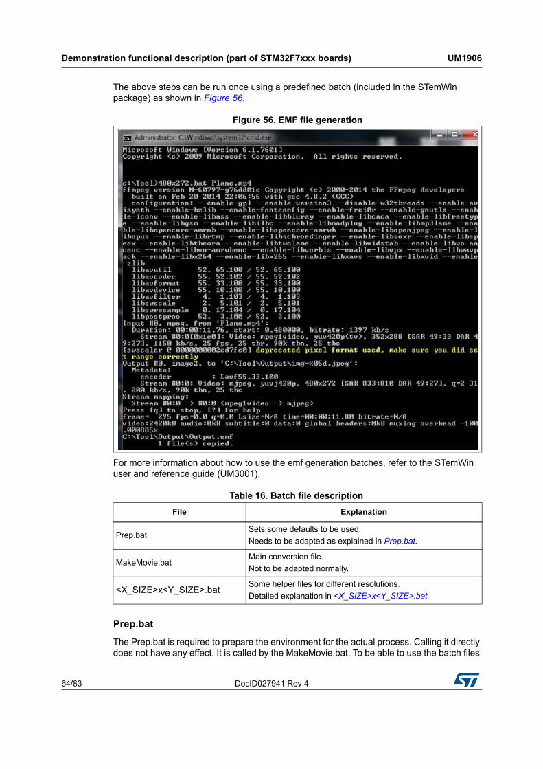
The above steps can be run once using a predefined batch (included in the STemWin package) as shown in Figure 56.
Figure 56. EMF file generation
For more information about how to use the emf generation batches, refer to the STemWin user and reference guide (UM3001).
Prep.bat
The Prep.bat is required to prepare the environment for the actual process. Calling it directly does not have any effect. It is called by the MakeMovie.bat. To be able to use the batch files
Table 16. Batch file description
File Explanation
Prep.batSets some defaults to be used.
Needs to be adapted as explained in Prep.bat.
MakeMovie.batMain conversion file.
Not to be adapted normally.
<X_SIZE>x<Y_SIZE>.batSome helper files for different resolutions.
Detailed explanation in <X_SIZE>x<Y_SIZE>.bat

DocID027941 Rev 4 65/83
UM1906 Demonstration functional description (part of STM32F7xxx boards)
82
it is required to adapt this file at first. This file sets variables used by the file MakeMovie.bat, they are listed in Table 17.
.
MakeMovie.bat
This is the main batch file used for the conversion process. Normally it is not required to change this file, but it is required to adapt Prep.bat first. It can be called with the parameters listed in Table 18:
Since the FFmpeg output can differ strongly from the output of previous actions, the MakeMovie.bat deletes all the output files in the first place. The output folder is defined by the environmental variable %OUTPUT% in Prep.bat. After that it uses FFmpeg.exe to create the required JPEG files for each frame. Afterwards it calls JPEG2Movie to create a single EMF file which can be used by STemWin directly. After the conversion operation the
Table 17. Variable description
Variable Description
%OUTPUT%Destination folder for the JPEG files.
Will be cleared automatically when starting the conversion with MakeMovie.bat.
%FFMPEG%Access variable for the FFmpeg tool.
Should contain the complete path required to call FFmpeg.exe.
%JPEG2MOVIE%Access variable for the JPEG2MOVIE tool.
Should contain the complete path required to call JPEG2Movie.exe.
%DEFAULT_SIZE%Default movie resolution to be used.
Can be ignored if one of the <X-SIZE>x<Y-SIZE>.bat files are used.
%DEFAULT_QUALITY%
Default quality to be used by FFmpeg.exe for creating the JPEG files.
The lower the number the better the quality. Value 1 indicates that a very good quality should be achieved, value 31 indicates the worst quality.
For more details, refer to the FFmpeg documentation.
%DEFAULT_FRAMERATE%
Frame rate in frames/second to be used by FFmpeg.
It defines the number of JPEG files to be generated by FFmpeg.exe for each second of the movie.
For more details, refer to the FFmpeg documentation.
Table 18. Parameter description
Parameter Description
%1 Movie file to be converted
%2 (optional)Size to be used.
If not given %DEFAULT_SIZE% of Prep.bat is used.
%3 (optional)Quality to be used.
If not given %DEFAULT_QUALITY% of Prep.bat is used.
%4 (optional)Frame rate to be used.
If not given %DEFAULT_FRAMERATE% of Prep.bat is used.
Demonstration functional description (part of STM32F7xxx boards) UM1906
66/83 DocID027941 Rev 4
result can be found in the conversion folder under FFmpeg.emf. It also creates a copy of that file into the source file folder. It has the same name as the source file with a size-postfix and .emf extension.
<X_SIZE>x<Y_SIZE>.bat
These files are small but useful helpers if several movie resolutions are required. The filenames of the batch files itself are used as parameter '-s' for FFmpeg.exe. The user can simply drag-and-drop the file to be converted to one of these helper files. After that an .emf file with the corresponding size-postfix can be found in the source file folder.
8.5 Game
overview
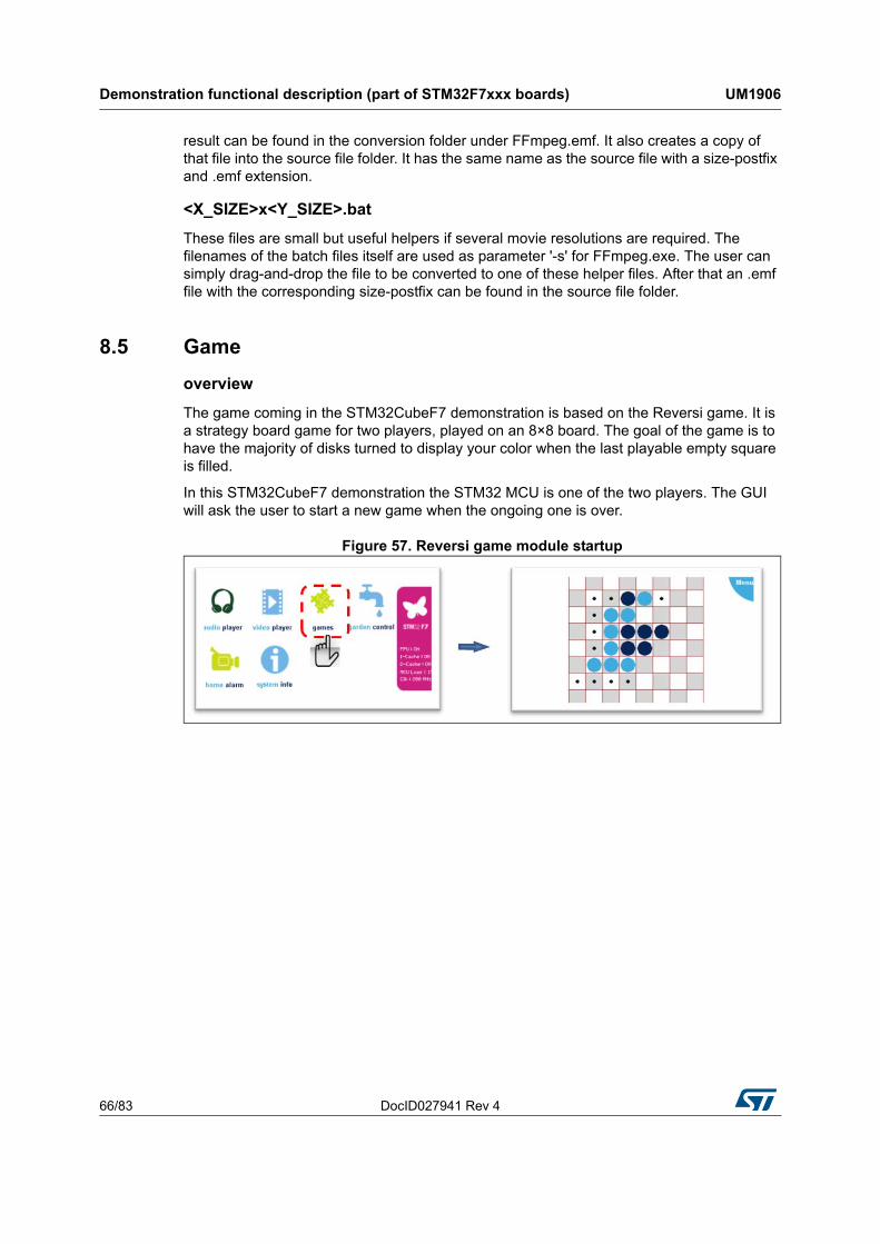
The game coming in the STM32CubeF7 demonstration is based on the Reversi game. It is a strategy board game for two players, played on an 8×8 board. The goal of the game is to have the majority of disks turned to display your color when the last playable empty square is filled.
In this STM32CubeF7 demonstration the STM32 MCU is one of the two players. The GUI will ask the user to start a new game when the ongoing one is over.
Figure 57. Reversi game module startup
DocID027941 Rev 4 67/83
UM1906 Demonstration functional description (part of STM32F7xxx boards)
82
8.6 Garden control
overview
The garden control module controls a garden watering system behavior, made with two independent circuits: one for a series of sprinklers and one for a drop wise system (Figure 58).
Figure 58. Garden control module startup
Note: This module is still in alpha version: only the controls are shown in the main frame. The final version will come later.
8.7 Home alarm
overview
The home alarm system is based on the integrated camera (in emulation mode fixed pictures are displayed for each room as shown in Figure 59).
Figure 59. Home alarm module startup
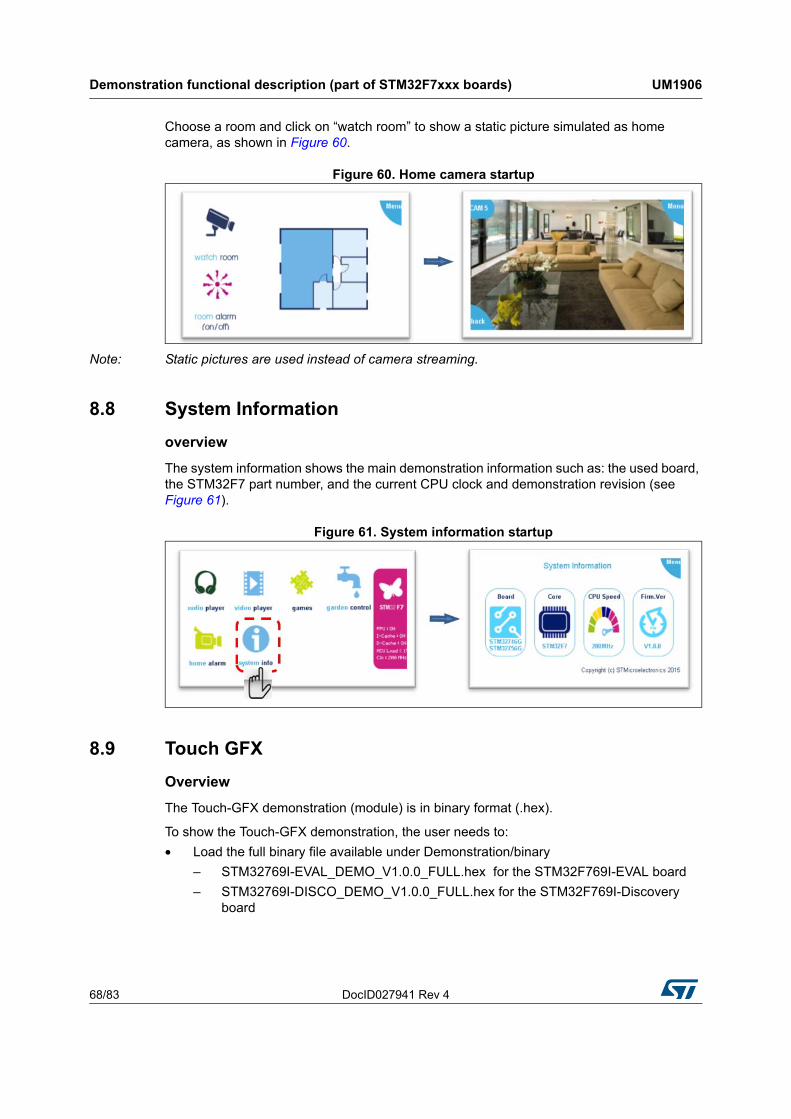
Demonstration functional description (part of STM32F7xxx boards) UM1906
68/83 DocID027941 Rev 4
Choose a room and click on “watch room” to show a static picture simulated as home camera, as shown in Figure 60.
Figure 60. Home camera startup
Note: Static pictures are used instead of camera streaming.
8.8 System Information
overview
The system information shows the main demonstration information such as: the used board, the STM32F7 part number, and the current CPU clock and demonstration revision (see Figure 61).
Figure 61. System information startup
8.9 Touch GFX
Overview
The Touch-GFX demonstration (module) is in binary format (.hex).
To show the Touch-GFX demonstration, the user needs to:
• Load the full binary file available under Demonstration/binary
– STM32769I-EVAL_DEMO_V1.0.0_FULL.hex for the STM32F769I-EVAL board
– STM32769I-DISCO_DEMO_V1.0.0_FULL.hex for the STM32F769I-Discovery board
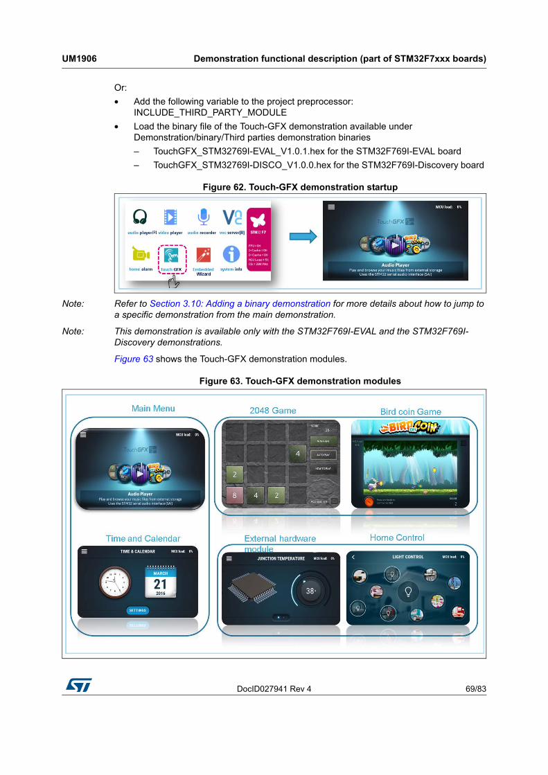
DocID027941 Rev 4 69/83
UM1906 Demonstration functional description (part of STM32F7xxx boards)
82
Or:
• Add the following variable to the project preprocessor: INCLUDE_THIRD_PARTY_MODULE
• Load the binary file of the Touch-GFX demonstration available under Demonstration/binary/Third parties demonstration binaries
– TouchGFX_STM32769I-EVAL_V1.0.1.hex for the STM32F769I-EVAL board
– TouchGFX_STM32769I-DISCO_V1.0.0.hex for the STM32F769I-Discovery board
Figure 62. Touch-GFX demonstration startup
Note: Refer to Section 3.10: Adding a binary demonstration for more details about how to jump to a specific demonstration from the main demonstration.
Note: This demonstration is available only with the STM32F769I-EVAL and the STM32F769I-Discovery demonstrations.
Figure 63 shows the Touch-GFX demonstration modules.
Figure 63. Touch-GFX demonstration modules

Demonstration functional description (part of STM32F7xxx boards) UM1906
70/83 DocID027941 Rev 4
Figure 64 describes the Video/audio player modules.
Figure 64. Video/audio player module
8.10 Embedded wizard
Overview
The embedded wizard demonstration (module) is in binary format (.hex).
To show the embedded wizard demonstration, the user needs to:
• Load the full binary file available under Demonstration/binary:
– STM32769I-EVAL_DEMO_V1.0.0_FULL.hex for the STM32F769I-EVAL board
– STM32769I-DISCO_DEMO_V1.0.0_FULL.hex for the STM32F769I-Discovery board
Or:
• Add the following variable to the project preprocessor: INCLUDE_THIRD_PARTY_MODULE
• Load the binary file of the embedded wizard demonstration available under Demonstration/binary/Third parties demonstration binaries:
– EmWi-DemoGUIs_STM32F769.hex for the STM32F769I-EVAL board
– EmWi-DemoGUIs_STM32F769-DISCO.hex for the STM32F769I-Discovery board
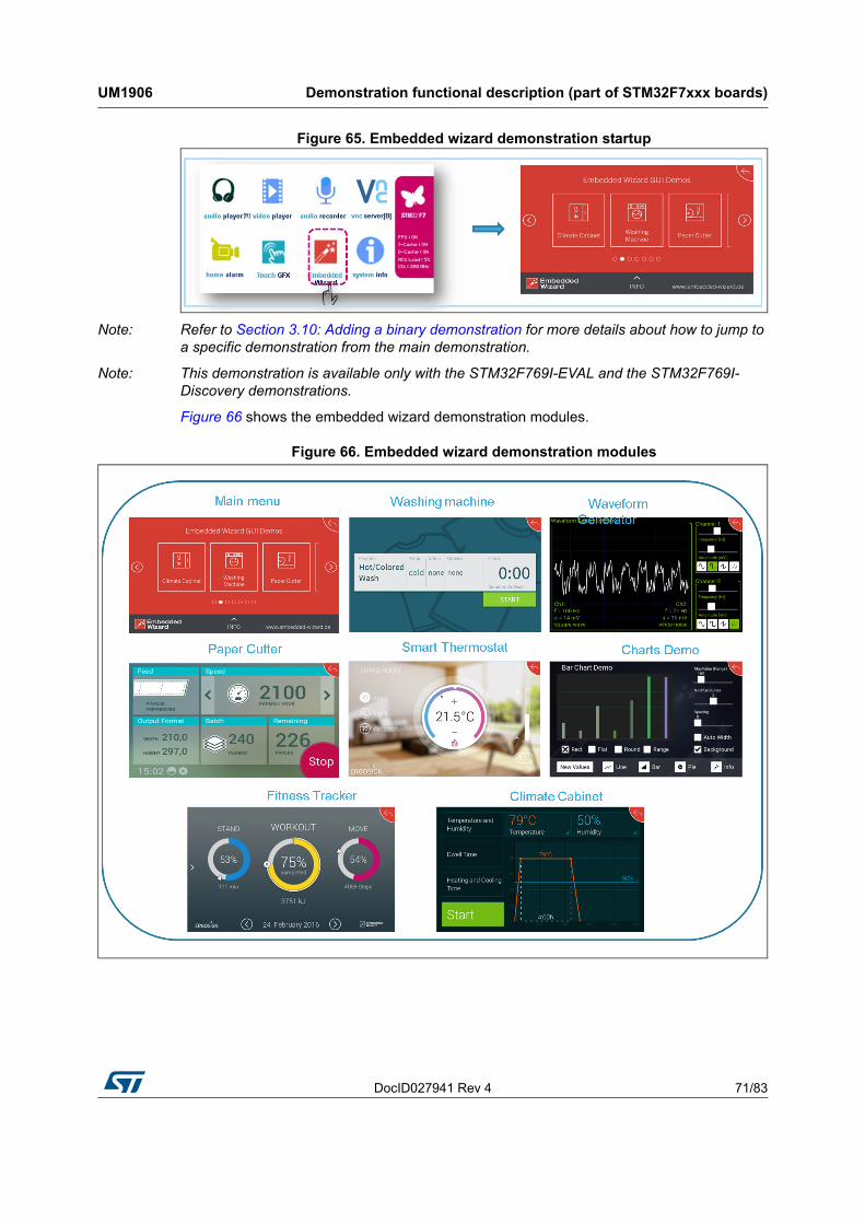
DocID027941 Rev 4 71/83
UM1906 Demonstration functional description (part of STM32F7xxx boards)
82
Figure 65. Embedded wizard demonstration startup
Note: Refer to Section 3.10: Adding a binary demonstration for more details about how to jump to a specific demonstration from the main demonstration.
Note: This demonstration is available only with the STM32F769I-EVAL and the STM32F769I-Discovery demonstrations.
Figure 66 shows the embedded wizard demonstration modules.
Figure 66. Embedded wizard demonstration modules
Demonstration functional description (STM32F723E-Discovery) UM1906
72/83 DocID027941 Rev 4
9 Demonstration functional description (STM32F723E-Discovery)
9.1 Audio player
Overview
The audio player module provides a complete audio solution based on the STM32F7xxx device and delivers a high-quality music experience. It supports playing music in WAV format but may be extended to support other compressed formats such as MP3 and WMA audio formats.
Features
• Audio format: WAV format without compression with 8 k to 96 k sampling
• Audio files stored in USB Disk Flash
• Only 8 Kbytes of RAM required for audio processing
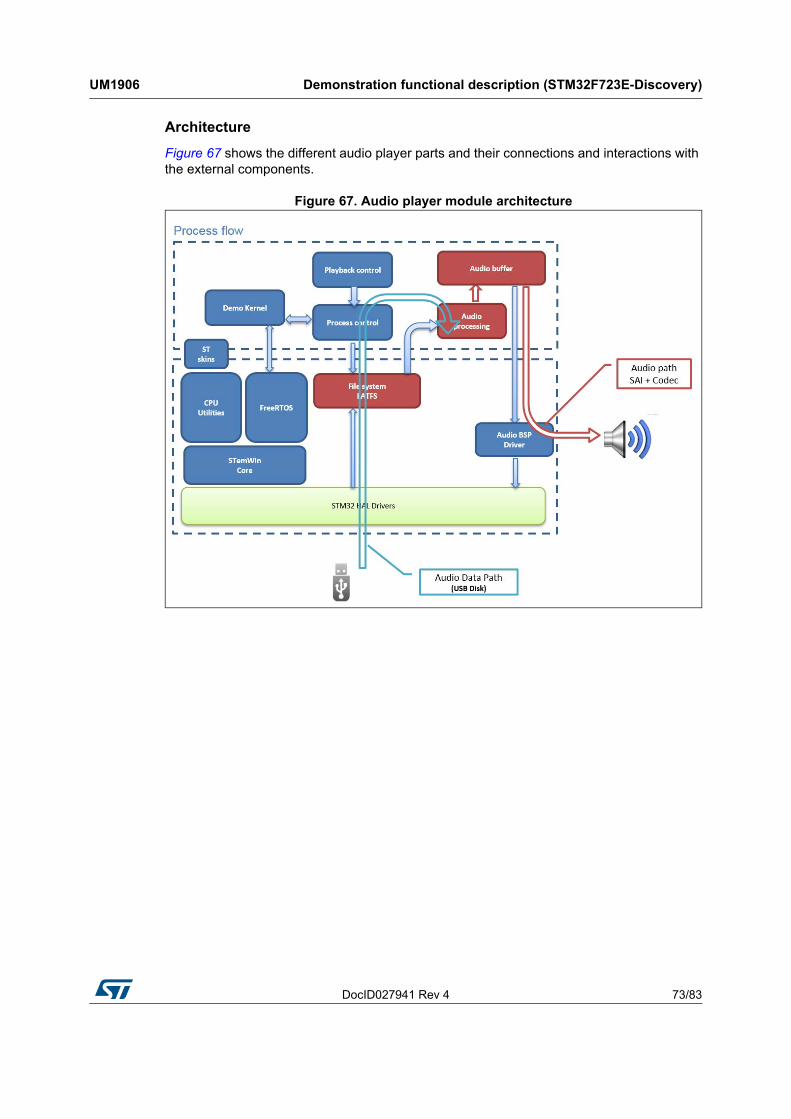
DocID027941 Rev 4 73/83
UM1906 Demonstration functional description (STM32F723E-Discovery)
82
Architecture
Figure 67 shows the different audio player parts and their connections and interactions with the external components.
Figure 67. Audio player module architecture
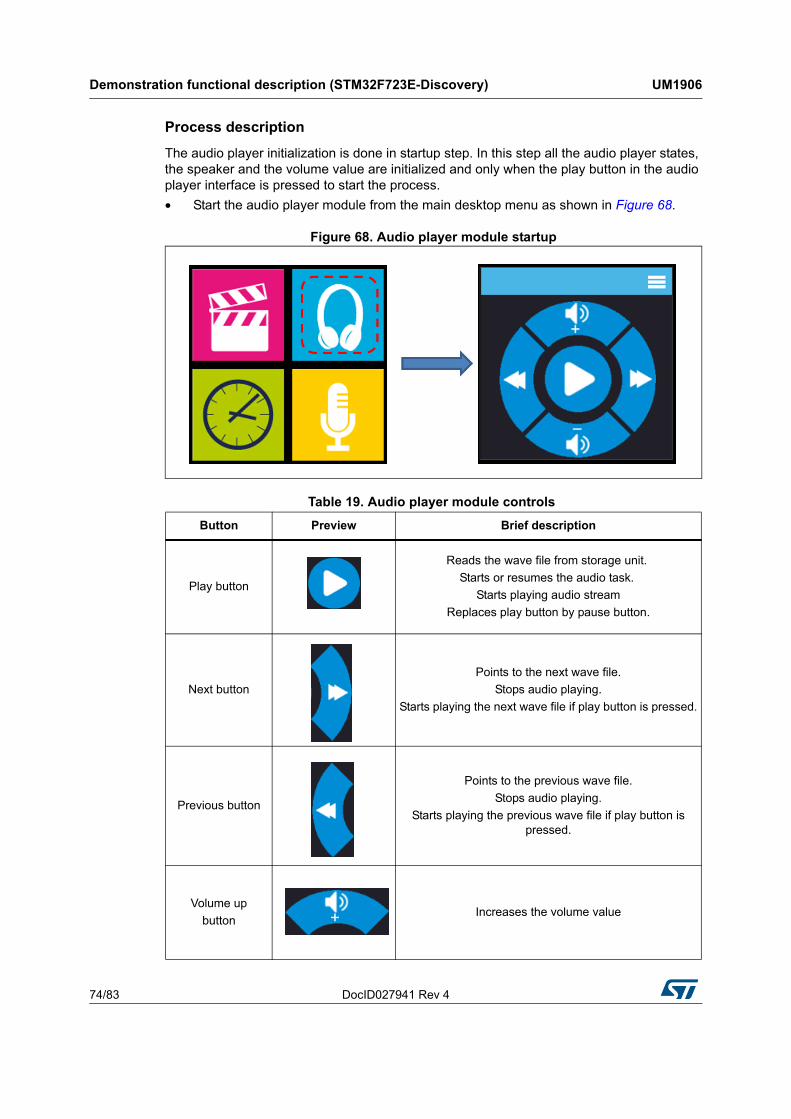
Demonstration functional description (STM32F723E-Discovery) UM1906
74/83 DocID027941 Rev 4
Process description
The audio player initialization is done in startup step. In this step all the audio player states, the speaker and the volume value are initialized and only when the play button in the audio player interface is pressed to start the process.
• Start the audio player module from the main desktop menu as shown in Figure 68.
Figure 68. Audio player module startup
Table 19. Audio player module controls
Button Preview Brief description
Play button
Reads the wave file from storage unit.
Starts or resumes the audio task.
Starts playing audio stream
Replaces play button by pause button.
Next button
Points to the next wave file.
Stops audio playing.
Starts playing the next wave file if play button is pressed.
Previous button
Points to the previous wave file.
Stops audio playing.
Starts playing the previous wave file if play button is pressed.
Volume up
buttonIncreases the volume value
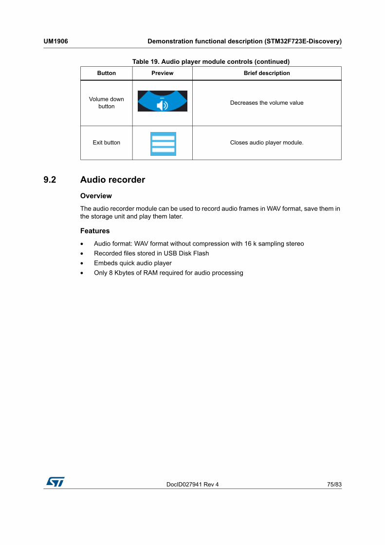
DocID027941 Rev 4 75/83
UM1906 Demonstration functional description (STM32F723E-Discovery)
82
9.2 Audio recorder
Overview
The audio recorder module can be used to record audio frames in WAV format, save them in the storage unit and play them later.
Features
• Audio format: WAV format without compression with 16 k sampling stereo
• Recorded files stored in USB Disk Flash
• Embeds quick audio player
• Only 8 Kbytes of RAM required for audio processing
Volume down button
Decreases the volume value
Exit button Closes audio player module.
Table 19. Audio player module controls (continued)
Button Preview Brief description
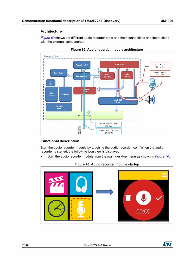
Demonstration functional description (STM32F723E-Discovery) UM1906
76/83 DocID027941 Rev 4
Architecture
Figure 69 shows the different audio recorder parts and their connections and interactions with the external components.
Figure 69. Audio recorder module architecture
Functional description
Start the audio recorder module by touching the audio recorder icon. When the audio recorder is started, the following icon view is displayed.
• Start the audio recorder module from the main desktop menu as shown in Figure 70.
Figure 70. Audio recorder module startup
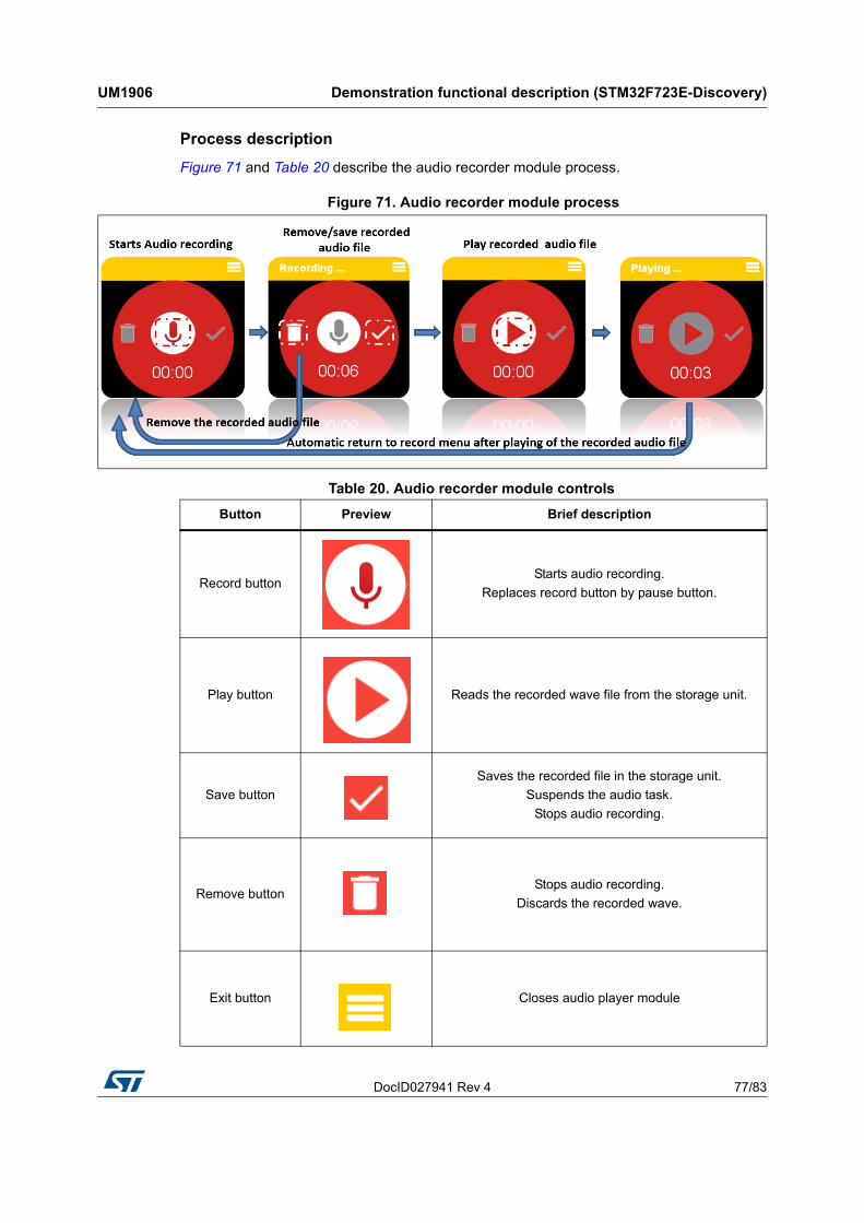
DocID027941 Rev 4 77/83
UM1906 Demonstration functional description (STM32F723E-Discovery)
82
Process description
Figure 71 and Table 20 describe the audio recorder module process.
Figure 71. Audio recorder module process
Table 20. Audio recorder module controls
Button Preview Brief description
Record buttonStarts audio recording.
Replaces record button by pause button.
Play button Reads the recorded wave file from the storage unit.
Save button
Saves the recorded file in the storage unit.
Suspends the audio task.
Stops audio recording.
Remove buttonStops audio recording.
Discards the recorded wave.
Exit button Closes audio player module
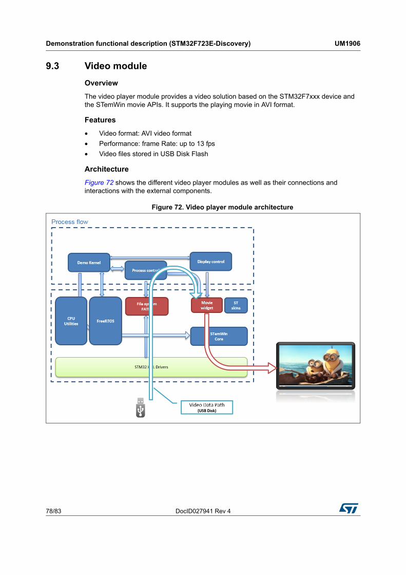
Demonstration functional description (STM32F723E-Discovery) UM1906
78/83 DocID027941 Rev 4
9.3 Video module
Overview
The video player module provides a video solution based on the STM32F7xxx device and the STemWin movie APIs. It supports the playing movie in AVI format.
Features
• Video format: AVI video format
• Performance: frame Rate: up to 13 fps
• Video files stored in USB Disk Flash
Architecture
Figure 72 shows the different video player modules as well as their connections and interactions with the external components.
Figure 72. Video player module architecture
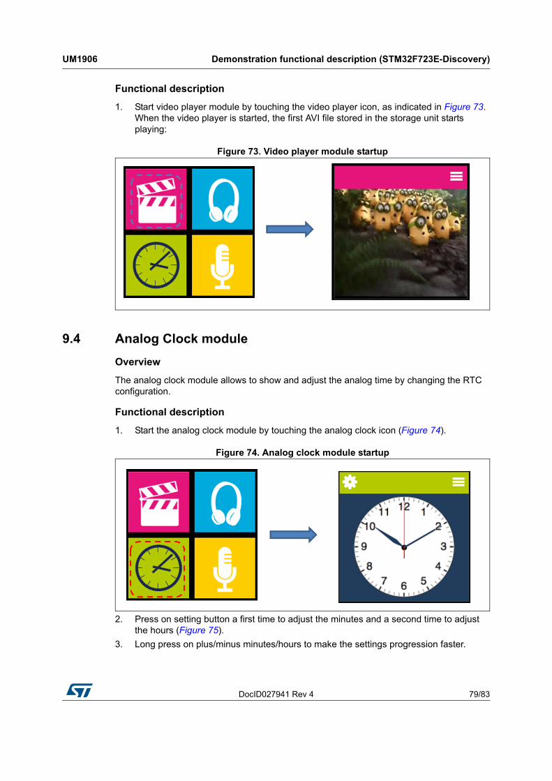
DocID027941 Rev 4 79/83
UM1906 Demonstration functional description (STM32F723E-Discovery)
82
Functional description
1. Start video player module by touching the video player icon, as indicated in Figure 73. When the video player is started, the first AVI file stored in the storage unit starts playing:
Figure 73. Video player module startup
9.4 Analog Clock module
Overview
The analog clock module allows to show and adjust the analog time by changing the RTC configuration.
Functional description
1. Start the analog clock module by touching the analog clock icon (Figure 74).
Figure 74. Analog clock module startup
2. Press on setting button a first time to adjust the minutes and a second time to adjust the hours (Figure 75).
3. Long press on plus/minus minutes/hours to make the settings progression faster.
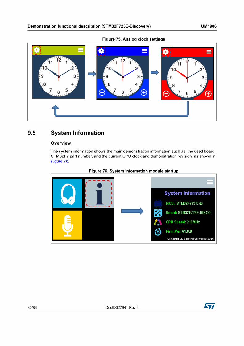
Demonstration functional description (STM32F723E-Discovery) UM1906
80/83 DocID027941 Rev 4
Figure 75. Analog clock settings
9.5 System Information
Overview
The system information shows the main demonstration information such as: the used board, STM32F7 part number, and the current CPU clock and demonstration revision, as shown in Figure 76.
Figure 76. System information module startup
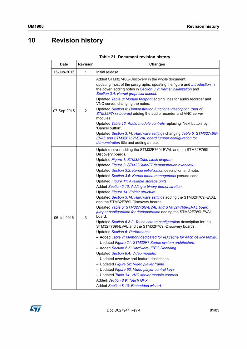
DocID027941 Rev 4 81/83
UM1906 Revision history
82
10 Revision history
Table 21. Document revision history
Date Revision Changes
15-Jun-2015 1 Initial release.
07-Sep-2015 2
Added STM32746G-Discovery in the whole document:
updating most of the paragraphs, updating the figure and Introduction in the cover, adding notes in Section 3.2: Kernel initialization and Section 3.4: Kernel graphical aspect.
Updated Table 8: Module footprint adding lines for audio recorder and VNC server, changing the notes.
Updated Section 8: Demonstration functional description (part of STM32F7xxx boards) adding the audio recorder and VNC server modules.
Updated Table 13: Audio module controls replacing ‘Next button’ by ‘Cancel button’.
Updated Section 3.14: Hardware settings changing Table 5: STM327x6G-EVAL and STM32F769I-EVAL board jumper configuration for demonstration title and adding a note.
06-Jul-2016 3
Updated cover adding the STM32F769I-EVAL and the STM32F769I-Discovery boards.
Updated Figure 1: STM32Cube block diagram.
Updated Figure 2: STM32CubeF7 demonstration overview.
Updated Section 3.2: Kernel initialization description and note.
Updated Section 3.6: Kernel menu management pseudo code.
Updated Figure 11: Available storage units.
Added Section 3.10: Adding a binary demonstration.
Updated Figure 14: Folder structure.
Updated Section 3.14: Hardware settings adding the STM32F769I-EVAL and the STM32F769I-Discovery boards.
Updated Table 5: STM327x6G-EVAL and STM32F769I-EVAL board jumper configuration for demonstration adding the STM32F769I-EVAL board.
Updated Section 5.3.2: Touch screen configuration description for the STM32F769I-EVAL and the STM32F769I-Discovery boards.
Updated Section 6: Performance:
– Added Table 7: Memory dedicated for I/D cache for each device family.
– Updated Figure 21: STM32F7 Series system architecture.
– Added Section 6.5: Hardware JPEG Decoding.
Updated Section 8.4: Video module:
– Updated overview and feature description.
– Updated Figure 52: Video player frame.
– Updated Figure 53: Video player control keys.
– Updated Table 14: VNC server module controls.
Added Section 8.9: Touch GFX.
Added Section 8.10: Embedded wizard.
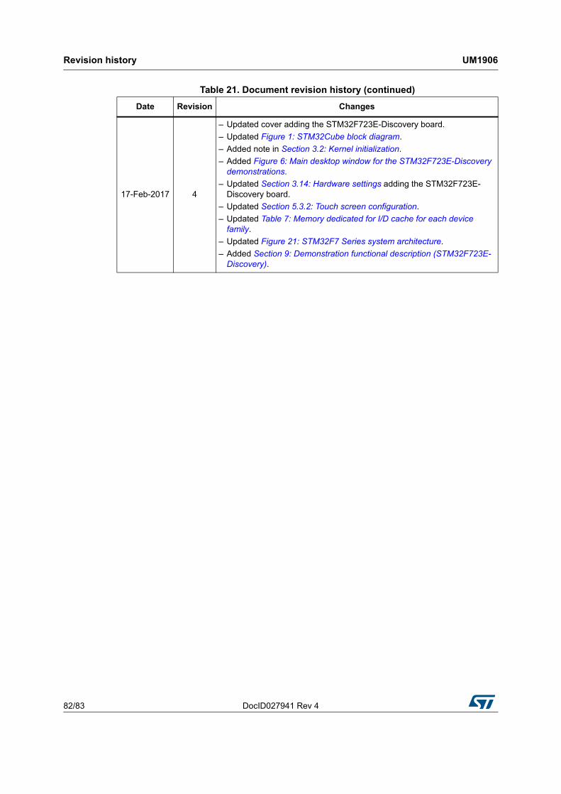
Revision history UM1906
82/83 DocID027941 Rev 4
17-Feb-2017 4
– Updated cover adding the STM32F723E-Discovery board.
– Updated Figure 1: STM32Cube block diagram.
– Added note in Section 3.2: Kernel initialization.
– Added Figure 6: Main desktop window for the STM32F723E-Discovery demonstrations.
– Updated Section 3.14: Hardware settings adding the STM32F723E-Discovery board.
– Updated Section 5.3.2: Touch screen configuration.
– Updated Table 7: Memory dedicated for I/D cache for each device family.
– Updated Figure 21: STM32F7 Series system architecture.
– Added Section 9: Demonstration functional description (STM32F723E-Discovery).
Table 21. Document revision history (continued)
Date Revision Changes
DocID027941 Rev 4 83/83
UM1906
83
IMPORTANT NOTICE – PLEASE READ CAREFULLY
STMicroelectronics NV and its subsidiaries (“ST”) reserve the right to make changes, corrections, enhancements, modifications, and improvements to ST products and/or to this document at any time without notice. Purchasers should obtain the latest relevant information on ST products before placing orders. ST products are sold pursuant to ST’s terms and conditions of sale in place at the time of order acknowledgement.
Purchasers are solely responsible for the choice, selection, and use of ST products and ST assumes no liability for application assistance or the design of Purchasers’ products.
No license, express or implied, to any intellectual property right is granted by ST herein.
Resale of ST products with provisions different from the information set forth herein shall void any warranty granted by ST for such product.
ST and the ST logo are trademarks of ST. All other product or service names are the property of their respective owners.
Information in this document supersedes and replaces information previously supplied in any prior versions of this document.
© 2017 STMicroelectronics – All rights reserved