Embed Size (px)
Citation preview
March 2018 UM2374 Rev 1 1/24
1
UM2374User manual
Getting started with STM32 motor control SDK v5.0
Introduction
STM32 microcontrollers offer the performance of the industry-standard Arm® Cortex®-M cores running either vector control (VC) or field-oriented control (FOC) modes, widely used in applications such as high-performance drives for air conditioning, home appliances, drones, building and industrial automation, medical, and e-bike.
The STM32 motor control software development kit (MC SDK) is part of the STMicroelectronics motor-control ecosystem, which offers a wide range of hardware and software solutions for motor control applications. It is referenced as X-CUBE-MCSDK or X-CUBE-MCSDK-FUL according to the software license agreement applied. It includes the:
• ST MC FOC firmware library for permanent-magnet synchronous motor (PMSM) field-oriented control
• ST MC Workbench software tool, a graphical user interface for the configuration of MC SDK firmware library parameters, including the ST Motor Profiler tool (MP)
The STM32 motor control software development kit allows evaluation of the performance of STM32 microcontrollers in applications driving single or dual three-phase permanent-magnet synchronous motors within the STM32 ecosystem.
The ST MC Workbench software tool runs on a PC. It reduces design time and effort when configuring the STM32 MC FOC FW library. Through its graphical user interface, it can generate all the configuration files needed for an application, as well as monitor and adjust some FOC algorithm variables in real time.
In addition, ST MC Workbench interfaces with STM32CubeMX to take advantage of its ecosystem and customize embedded applications.
www.st.com
Contents UM2374
2/24 UM2374 Rev 1
Contents
1 General information . . . . . . . . . . . . . . . . . . . . . . . . . . . . . . . . . . . . . . . . . 5
2 Motor control ecosystem setup . . . . . . . . . . . . . . . . . . . . . . . . . . . . . . . . 6
2.1 Software tool setup . . . . . . . . . . . . . . . . . . . . . . . . . . . . . . . . . . . . . . . . . . . 6
2.2 Hardware setup . . . . . . . . . . . . . . . . . . . . . . . . . . . . . . . . . . . . . . . . . . . . . 7
3 Getting Started . . . . . . . . . . . . . . . . . . . . . . . . . . . . . . . . . . . . . . . . . . . . . 8
3.1 Hardware connection . . . . . . . . . . . . . . . . . . . . . . . . . . . . . . . . . . . . . . . . . 8
3.2 Motor profiling . . . . . . . . . . . . . . . . . . . . . . . . . . . . . . . . . . . . . . . . . . . . . . . 8
3.3 MC project generation . . . . . . . . . . . . . . . . . . . . . . . . . . . . . . . . . . . . . . . 13
3.4 Motor-control project compilation . . . . . . . . . . . . . . . . . . . . . . . . . . . . . . . 18
3.5 MC embedded application download . . . . . . . . . . . . . . . . . . . . . . . . . . . . 18
3.6 Spinning motor control and monitoring . . . . . . . . . . . . . . . . . . . . . . . . . . . 19
4 Precaution of use and restrictions . . . . . . . . . . . . . . . . . . . . . . . . . . . . 22
Revision history . . . . . . . . . . . . . . . . . . . . . . . . . . . . . . . . . . . . . . . . . . . . . . . . . . . . 23
UM2374 Rev 1 3/24
UM2374 List of tables
3
List of tables
Table 1. List of acronyms . . . . . . . . . . . . . . . . . . . . . . . . . . . . . . . . . . . . . . . . . . . . . . . . . . . . . . . . . . 5Table 2. Document revision history . . . . . . . . . . . . . . . . . . . . . . . . . . . . . . . . . . . . . . . . . . . . . . . . . 23
List of figures UM2374
4/24 UM2374 Rev 1
List of figures
Figure 1. ST MC Workbench - Icon and installation folder tree . . . . . . . . . . . . . . . . . . . . . . . . . . . . . . 8Figure 2. ST MC Workbench - GUI expanded top view. . . . . . . . . . . . . . . . . . . . . . . . . . . . . . . . . . . . 8Figure 3. ST Motor Profiler - GUI . . . . . . . . . . . . . . . . . . . . . . . . . . . . . . . . . . . . . . . . . . . . . . . . . . . . . 9Figure 4. ST Motor Profiler - Hardware setup list examples . . . . . . . . . . . . . . . . . . . . . . . . . . . . . . . 10Figure 5. ST Motor Profiler - SM-PMSM parameters example . . . . . . . . . . . . . . . . . . . . . . . . . . . . . 11Figure 6. ST Motor Profiler - I-PMSM parameters example. . . . . . . . . . . . . . . . . . . . . . . . . . . . . . . . 11Figure 7. ST Motor Profiler - Measurement results . . . . . . . . . . . . . . . . . . . . . . . . . . . . . . . . . . . . . . 12Figure 8. ST Motor Profiler - Save window . . . . . . . . . . . . . . . . . . . . . . . . . . . . . . . . . . . . . . . . . . . . 13Figure 9. ST MC Workbench - New Project window . . . . . . . . . . . . . . . . . . . . . . . . . . . . . . . . . . . . . 14Figure 10. ST MC Workbench - New Project Info window. . . . . . . . . . . . . . . . . . . . . . . . . . . . . . . . . . 14Figure 11. ST MC Workbench - Project Settings . . . . . . . . . . . . . . . . . . . . . . . . . . . . . . . . . . . . . . . . . 15Figure 12. ST MC Workbench - Project Settings window . . . . . . . . . . . . . . . . . . . . . . . . . . . . . . . . . . 15Figure 13. ST MC Workbench - Project generation button . . . . . . . . . . . . . . . . . . . . . . . . . . . . . . . . . 16Figure 14. ST MC Workbench - Workspace selection . . . . . . . . . . . . . . . . . . . . . . . . . . . . . . . . . . . . . 16Figure 15. ST MC Workbench - Project generation build info . . . . . . . . . . . . . . . . . . . . . . . . . . . . . . . 17Figure 16. IDE - MC Project view example . . . . . . . . . . . . . . . . . . . . . . . . . . . . . . . . . . . . . . . . . . . . . 18Figure 17. ST MC Workbench - Motor monitoring button . . . . . . . . . . . . . . . . . . . . . . . . . . . . . . . . . . 19Figure 18. ST MC Workbench - Motor monitoring GUI . . . . . . . . . . . . . . . . . . . . . . . . . . . . . . . . . . . . 20Figure 19. ST MC Workbench - Use of the motor control and monitoring . . . . . . . . . . . . . . . . . . . . . . 21
UM2374 Rev 1 5/24
UM2374 General information
23
1 General information
The MC SDK is used for the development of motor-control applications running on STM32 32-bit microcontrollers based on the Arm® Cortex®-M processor.
Table 1 presents the definition of acronyms that are relevant for a better understanding of this document.
More information about ST MC Workbench is provided in the STM32 motor control SDK v5.0 tools user manual (UM2380) available at www.st.com.
Table 1. List of acronyms
Acronym Description
GUI Graphical user interface
IDE Integrated development environment
FOC Field-oriented control
FW Firmware
MC Motor control
MC WB Motor control Workbench (STMicroelectronics SW tool)
MP Motor Profiler (STMicroelectronics software tool)
PMSM Permanent-magnet synchronous motor
PWM Pulse-width modulation
SDK Software development kit
VC Vector control
Motor control ecosystem setup UM2374
6/24 UM2374 Rev 1
2 Motor control ecosystem setup
A suitable ST Motor Control ecosystem environment includes:
• A PC running the needed MC software tools
• A third-party IDE
• A third-party ANSI C-compiler
• A JTAG/SWD interface for debugging and programming
• An STMicroelectronics application board with one of the STM32 microcontrollers supported. It drives the power stage and features:
– PWM outputs to gate driver
– ADC channels to measure currents
– DC bus voltage
• A three-phase PMSM motor
• A power supply
Refer to the STM32 motor control software development kit (MC SDK) data brief (DB3548) at www.st.com and to the release note for more details.
2.1 Software tool setup
The STMicroelectronics motor-control ecosystem runs on a PC with Windows® 7.
The following PC software tools are correctly installed:
• ST MC Workbench (v5.0.0 or later)
• STM32CubeMX (v4.24.0 or later)
• ST-LINK/V2 (v4.0.0 or later)
• Any supported IDE:
– IAR Embedded Workbench® for Arm® (v7.80.4)
– Keil® MDK tools (v5.24.2 or later)
– Ac6 System Workbench (v2.3.0 or later)(a)
Refer to the respective user manuals for proper installation. STMicroelectronics documents are available from the Internet site at www.st.com:
• STM32 motor control SDK v5.0 tools user manual (UM2380)
• STM32CubeMX for STM32 configuration and initialization C code generation user manual (UM1718)
• STM32 ST-LINK utility software description user manual (UM0892)
a. The AC6 tool framework is not supported in SDK v5.0 but in later versions.
UM2374 Rev 1 7/24
UM2374 Motor control ecosystem setup
23
2.2 Hardware setup
The connection of the STMicroelectronics application board to the PC requires a USB Type- A connector. Refer to the description of the application board for details on the USB cable.
A dedicated description card is delivered with each STMicroelectronics application board for proper installation. For more details, refer to the user manual of the board available at www.st.com.
The selected hardware can be one of the three setups:
• The complete MC Kit
• One of the complete inverter boards
• Any STM32 evaluation board combined with one of the ST evaluation power stages that include the MC connector
Getting Started UM2374
8/24 UM2374 Rev 1
3 Getting Started
Warning: Check that the board is correctly configured for the motor control application and supplied with the expected input voltage.
Note: Refer to the user manual of the related hardware to setup the correct configuration, voltage range, serial communication capabilities, and programming/debugging interface.
3.1 Hardware connection
Connect a USB cable between the PC and the STMicroelectronics application board and the JTAG/SWD programming cable if it is different from the USB cable.
3.2 Motor profiling
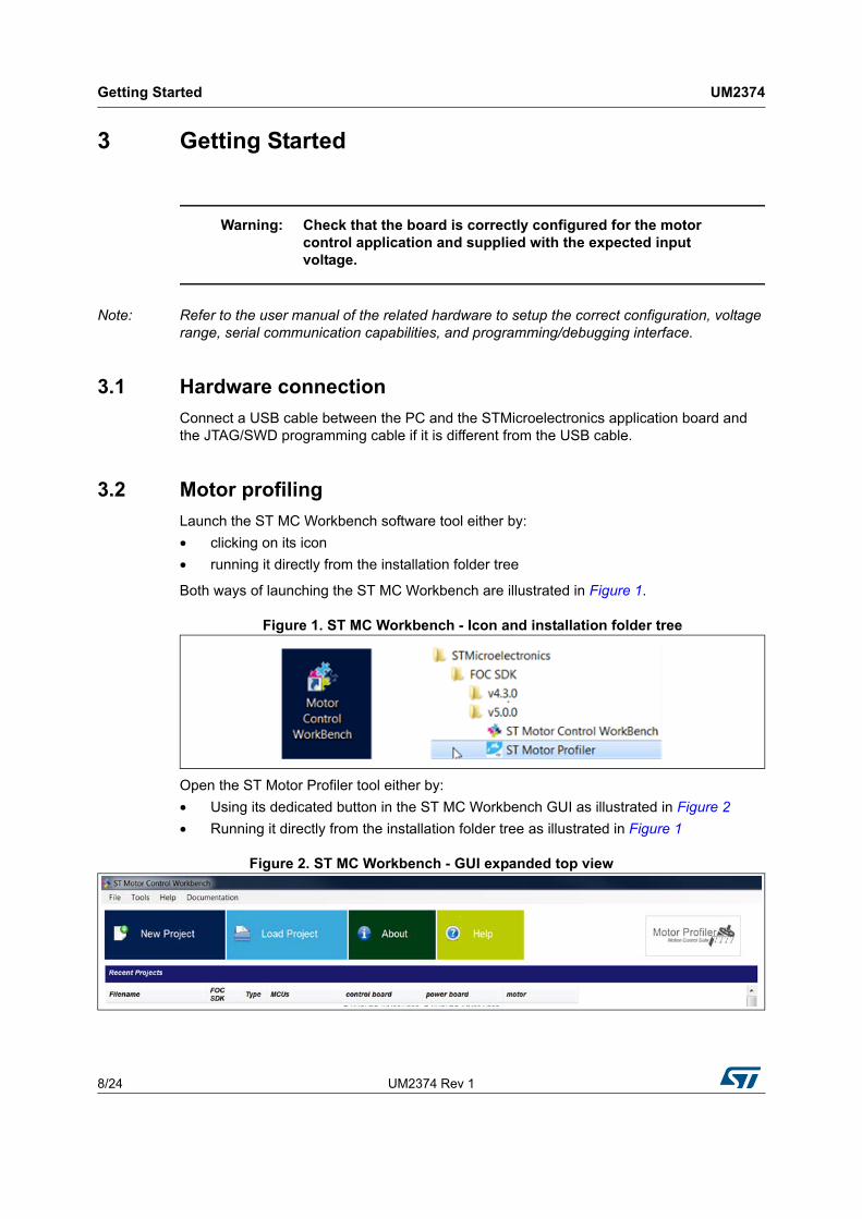
Launch the ST MC Workbench software tool either by:
• clicking on its icon
• running it directly from the installation folder tree
Both ways of launching the ST MC Workbench are illustrated in Figure 1.
Figure 1. ST MC Workbench - Icon and installation folder tree
Open the ST Motor Profiler tool either by:
• Using its dedicated button in the ST MC Workbench GUI as illustrated in Figure 2
• Running it directly from the installation folder tree as illustrated in Figure 1
Figure 2. ST MC Workbench - GUI expanded top view
UM2374 Rev 1 9/24
UM2374 Getting Started
23
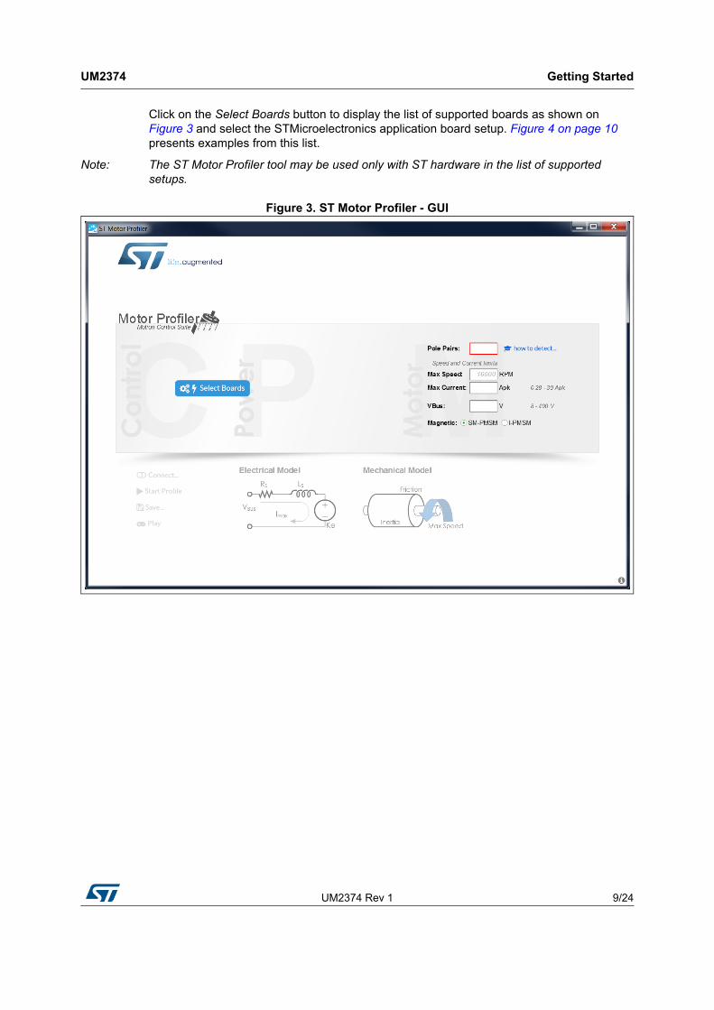
Click on the Select Boards button to display the list of supported boards as shown on Figure 3 and select the STMicroelectronics application board setup. Figure 4 on page 10 presents examples from this list.
Note: The ST Motor Profiler tool may be used only with ST hardware in the list of supported setups.
Figure 3. ST Motor Profiler - GUI
Getting Started UM2374
10/24 UM2374 Rev 1
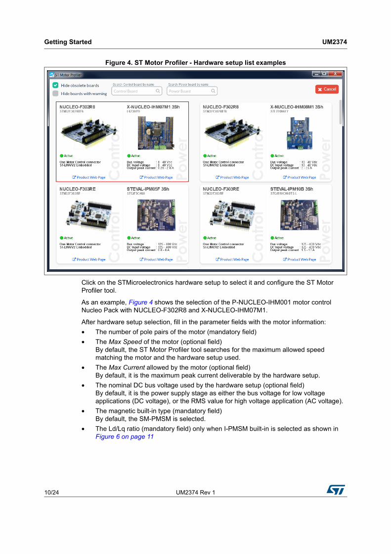
Figure 4. ST Motor Profiler - Hardware setup list examples
Click on the STMicroelectronics hardware setup to select it and configure the ST Motor Profiler tool.
As an example, Figure 4 shows the selection of the P-NUCLEO-IHM001 motor control Nucleo Pack with NUCLEO-F302R8 and X-NUCLEO-IHM07M1.
After hardware setup selection, fill in the parameter fields with the motor information:
• The number of pole pairs of the motor (mandatory field)
• The Max Speed of the motor (optional field) By default, the ST Motor Profiler tool searches for the maximum allowed speed matching the motor and the hardware setup used.
• The Max Current allowed by the motor (optional field) By default, it is the maximum peak current deliverable by the hardware setup.
• The nominal DC bus voltage used by the hardware setup (optional field) By default, it is the power supply stage as either the bus voltage for low voltage applications (DC voltage), or the RMS value for high voltage application (AC voltage).
• The magnetic built-in type (mandatory field) By default, the SM-PMSM is selected.
• The Ld/Lq ratio (mandatory field) only when I-PMSM built-in is selected as shown in Figure 6 on page 11
UM2374 Rev 1 11/24
UM2374 Getting Started
23
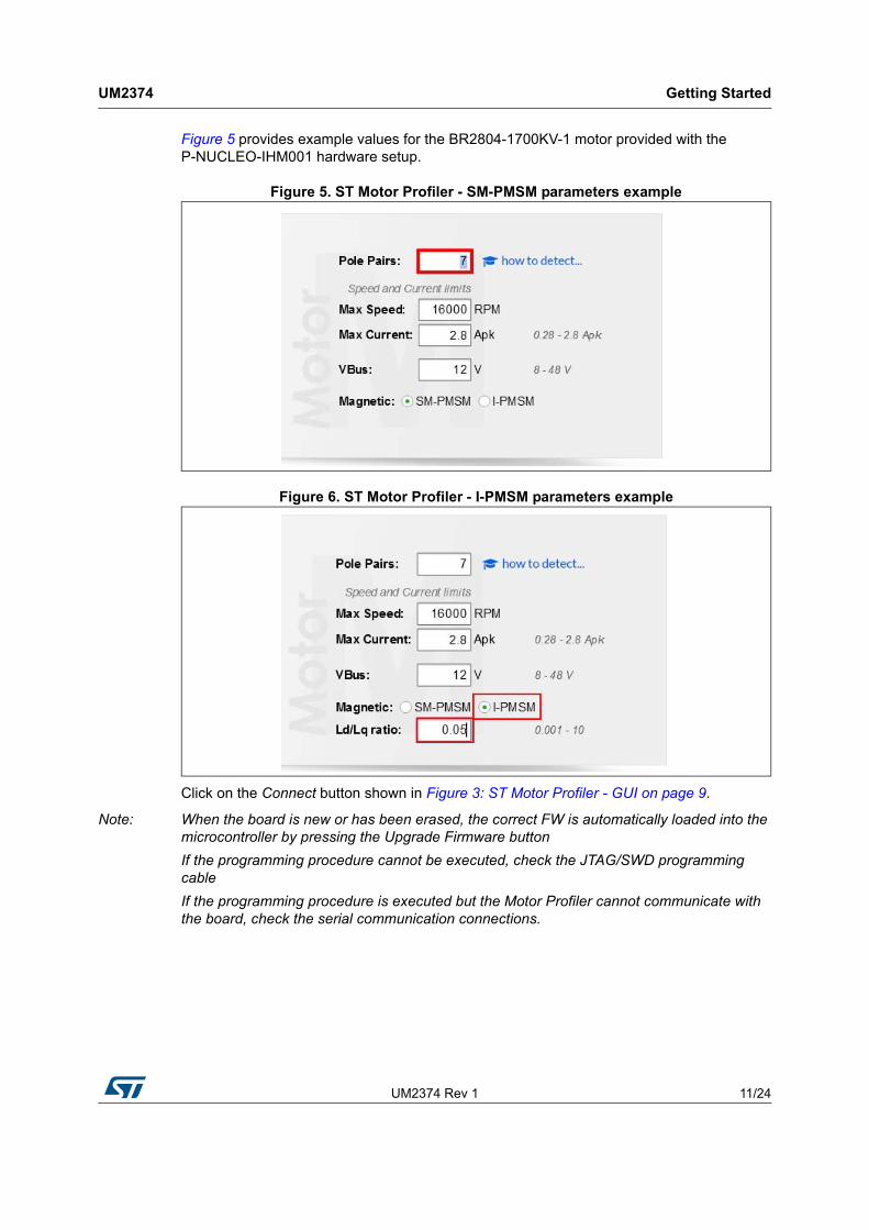
Figure 5 provides example values for the BR2804-1700KV-1 motor provided with the P-NUCLEO-IHM001 hardware setup.
Figure 5. ST Motor Profiler - SM-PMSM parameters example
Figure 6. ST Motor Profiler - I-PMSM parameters example
Click on the Connect button shown in Figure 3: ST Motor Profiler - GUI on page 9.
Note: When the board is new or has been erased, the correct FW is automatically loaded into the microcontroller by pressing the Upgrade Firmware button
If the programming procedure cannot be executed, check the JTAG/SWD programming cable
If the programming procedure is executed but the Motor Profiler cannot communicate with the board, check the serial communication connections.
Getting Started UM2374
12/24 UM2374 Rev 1
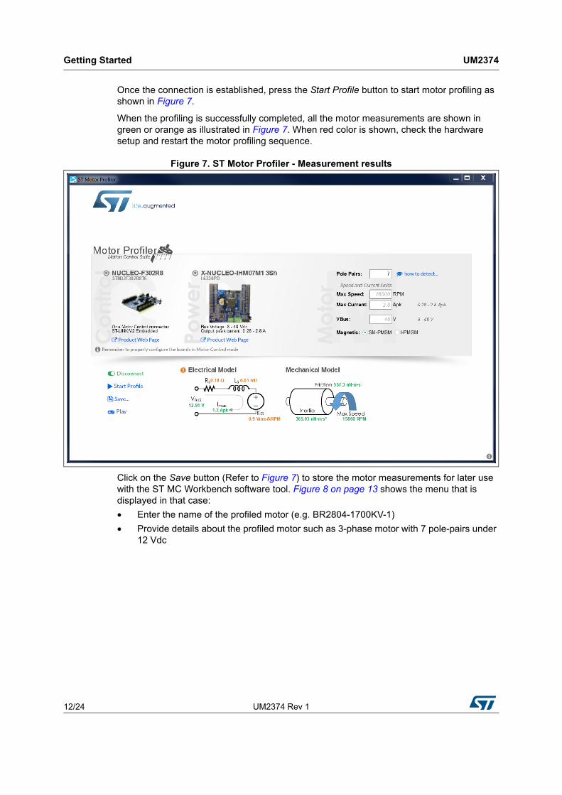
Once the connection is established, press the Start Profile button to start motor profiling as shown in Figure 7.
When the profiling is successfully completed, all the motor measurements are shown in green or orange as illustrated in Figure 7. When red color is shown, check the hardware setup and restart the motor profiling sequence.
Figure 7. ST Motor Profiler - Measurement results
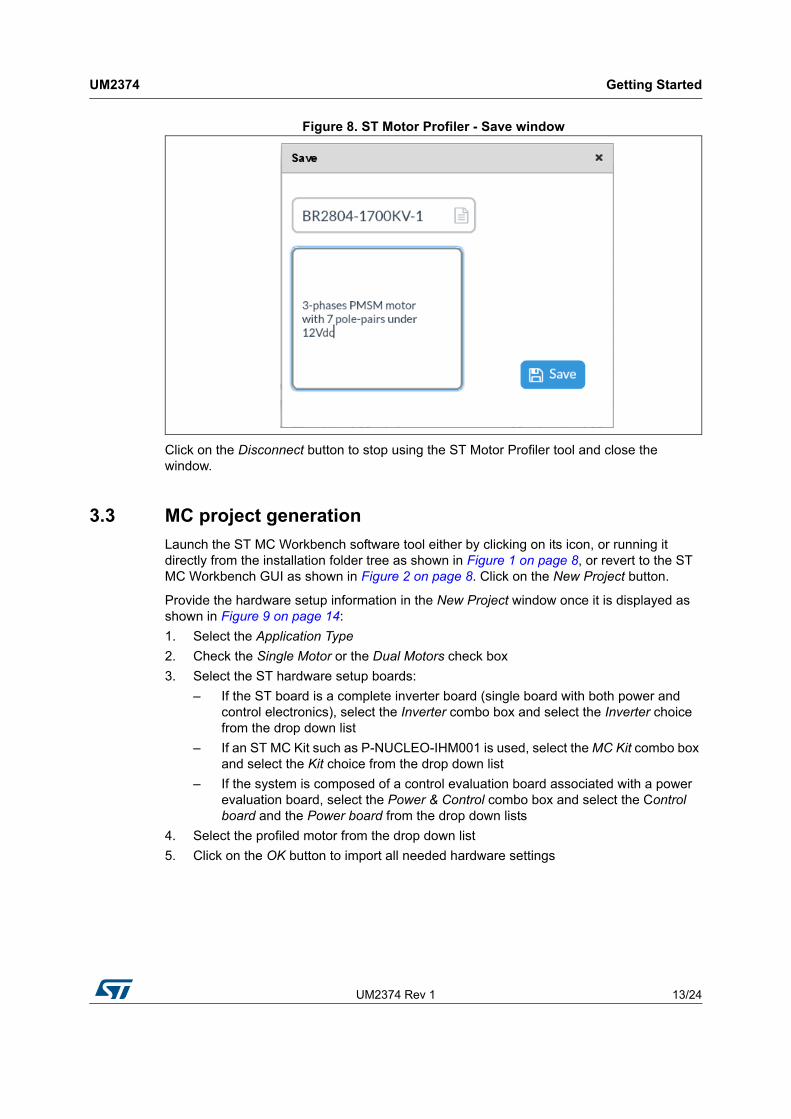
Click on the Save button (Refer to Figure 7) to store the motor measurements for later use with the ST MC Workbench software tool. Figure 8 on page 13 shows the menu that is displayed in that case:
• Enter the name of the profiled motor (e.g. BR2804-1700KV-1)
• Provide details about the profiled motor such as 3-phase motor with 7 pole-pairs under 12 Vdc
UM2374 Rev 1 13/24
UM2374 Getting Started
23
Figure 8. ST Motor Profiler - Save window
Click on the Disconnect button to stop using the ST Motor Profiler tool and close the window.
3.3 MC project generation
Launch the ST MC Workbench software tool either by clicking on its icon, or running it directly from the installation folder tree as shown in Figure 1 on page 8, or revert to the ST MC Workbench GUI as shown in Figure 2 on page 8. Click on the New Project button.
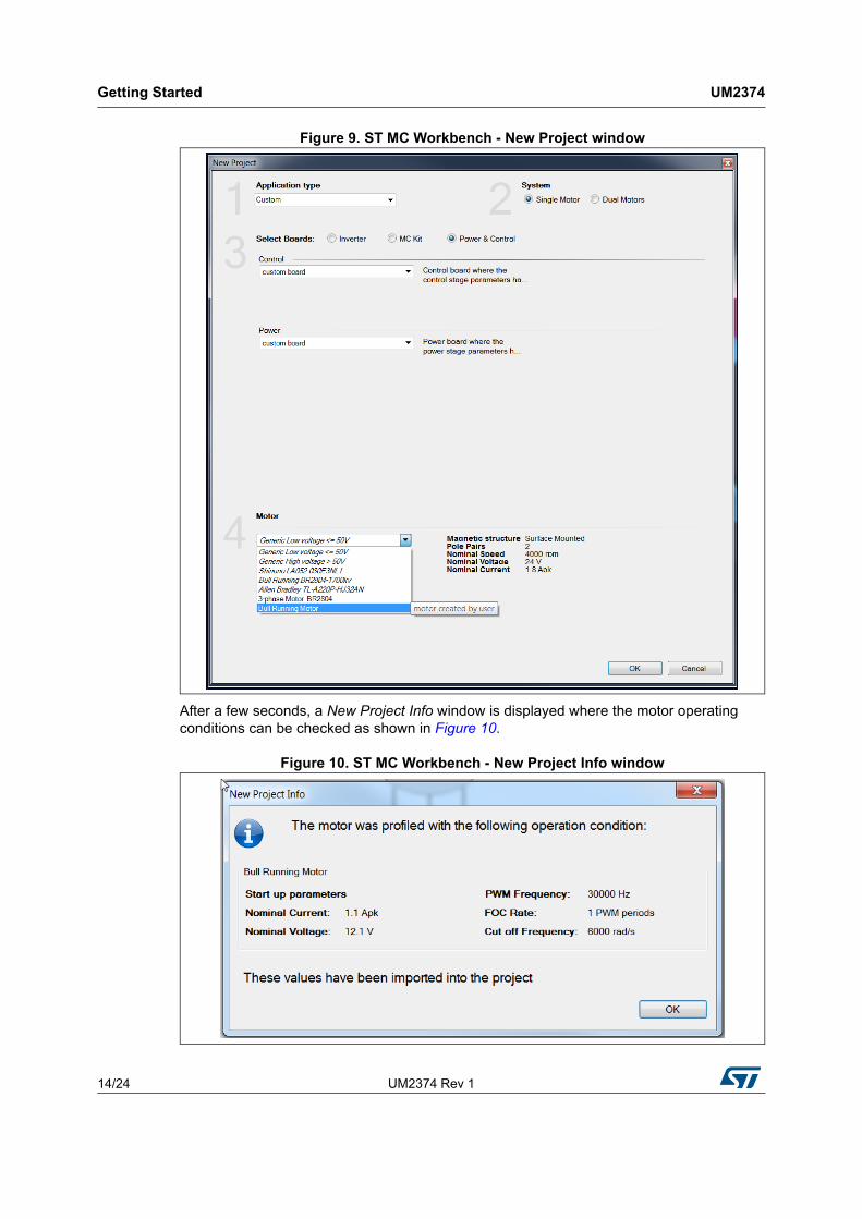
Provide the hardware setup information in the New Project window once it is displayed as shown in Figure 9 on page 14:
1. Select the Application Type
2. Check the Single Motor or the Dual Motors check box
3. Select the ST hardware setup boards:
– If the ST board is a complete inverter board (single board with both power and control electronics), select the Inverter combo box and select the Inverter choice from the drop down list
– If an ST MC Kit such as P-NUCLEO-IHM001 is used, select the MC Kit combo box and select the Kit choice from the drop down list
– If the system is composed of a control evaluation board associated with a power evaluation board, select the Power & Control combo box and select the Control board and the Power board from the drop down lists
4. Select the profiled motor from the drop down list
5. Click on the OK button to import all needed hardware settings
Getting Started UM2374
14/24 UM2374 Rev 1
Figure 9. ST MC Workbench - New Project window
After a few seconds, a New Project Info window is displayed where the motor operating conditions can be checked as shown in Figure 10.
Figure 10. ST MC Workbench - New Project Info window
UM2374 Rev 1 15/24
UM2374 Getting Started
23
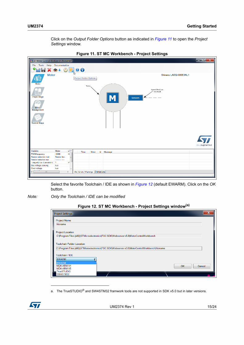
Click on the Output Folder Options button as indicated in Figure 11 to open the Project Settings window.
Figure 11. ST MC Workbench - Project Settings
Select the favorite Toolchain / IDE as shown in Figure 12 (default EWARM). Click on the OK button.
Note: Only the Toolchain / IDE can be modified
Figure 12. ST MC Workbench - Project Settings window(a)
a. The TrueSTUDIO® and SW4STM32 framwork tools are not supported in SDK v5.0 but in later versions.
Getting Started UM2374
16/24 UM2374 Rev 1
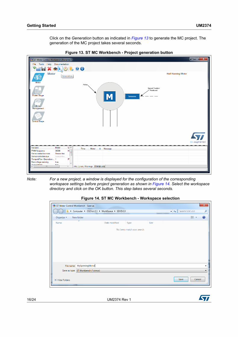
Click on the Generation button as indicated in Figure 13 to generate the MC project. The generation of the MC project takes several seconds.
Figure 13. ST MC Workbench - Project generation button
Note: For a new project, a window is displayed for the configuration of the corresponding workspace settings before project generation as shown in Figure 14. Select the workspace directory and click on the OK button. This step takes several seconds.
Figure 14. ST MC Workbench - Workspace selection
UM2374 Rev 1 17/24
UM2374 Getting Started
23
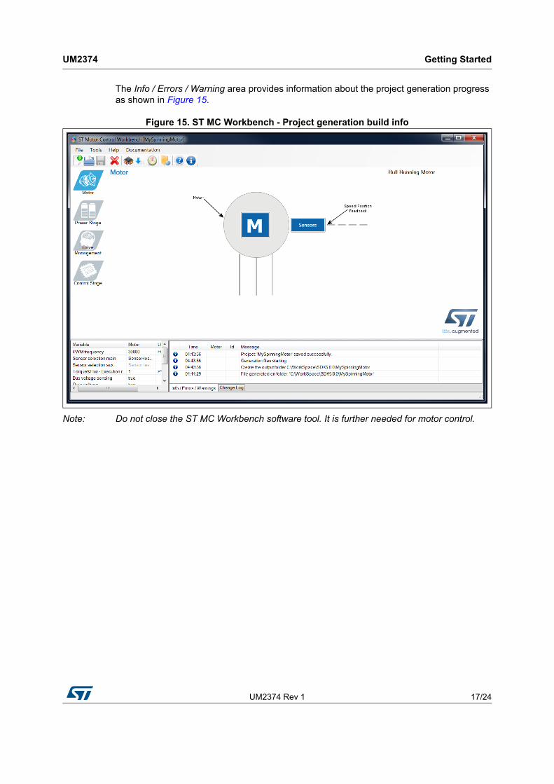
The Info / Errors / Warning area provides information about the project generation progress as shown in Figure 15.
Figure 15. ST MC Workbench - Project generation build info
Note: Do not close the ST MC Workbench software tool. It is further needed for motor control.
Getting Started UM2374
18/24 UM2374 Rev 1
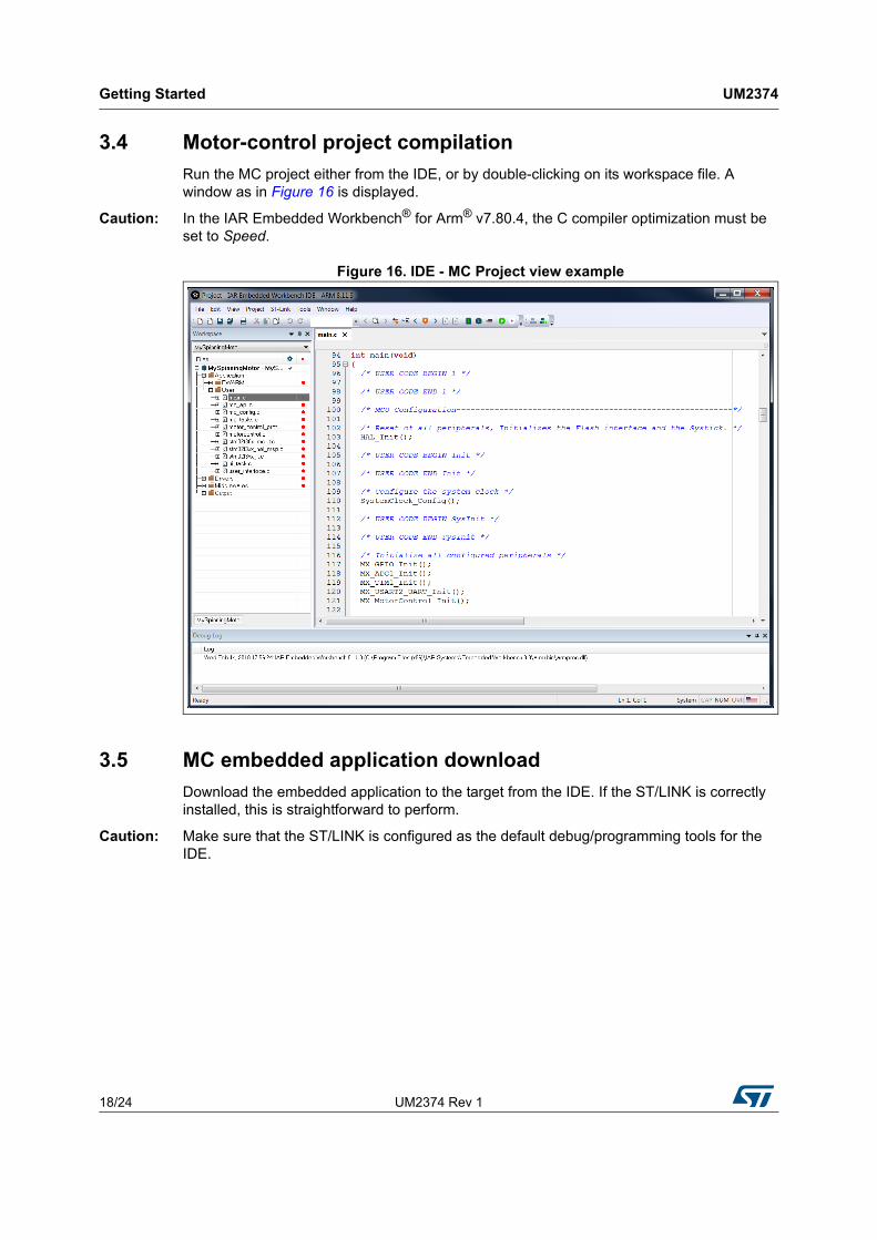
3.4 Motor-control project compilation
Run the MC project either from the IDE, or by double-clicking on its workspace file. A window as in Figure 16 is displayed.
Caution: In the IAR Embedded Workbench® for Arm® v7.80.4, the C compiler optimization must be set to Speed.
Figure 16. IDE - MC Project view example
3.5 MC embedded application download
Download the embedded application to the target from the IDE. If the ST/LINK is correctly installed, this is straightforward to perform.
Caution: Make sure that the ST/LINK is configured as the default debug/programming tools for the IDE.
UM2374 Rev 1 19/24
UM2374 Getting Started
23
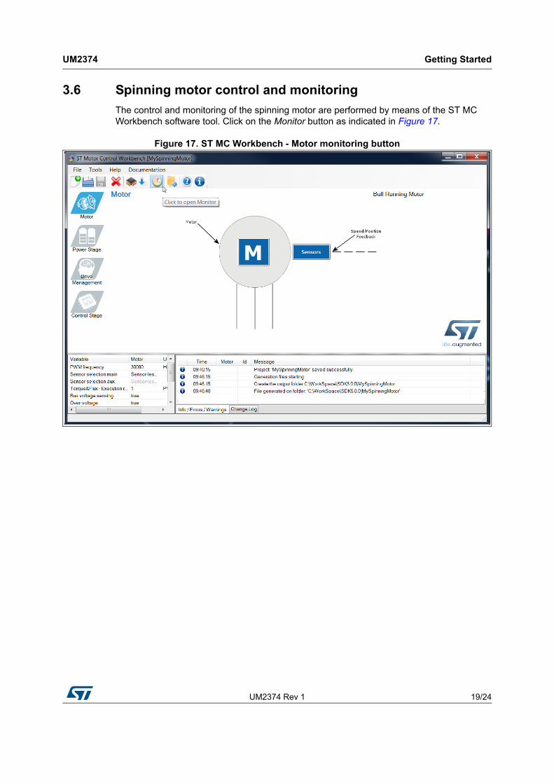
3.6 Spinning motor control and monitoring
The control and monitoring of the spinning motor are performed by means of the ST MC Workbench software tool. Click on the Monitor button as indicated in Figure 17.
Figure 17. ST MC Workbench - Motor monitoring button

Getting Started UM2374
20/24 UM2374 Rev 1
A control and monitoring GUI is displayed as shown in Figure 18. Check the communication link settings, configure it if needed, and click on the Connect button.
Figure 18. ST MC Workbench - Motor monitoring GUI
UM2374 Rev 1 21/24
UM2374 Getting Started
23
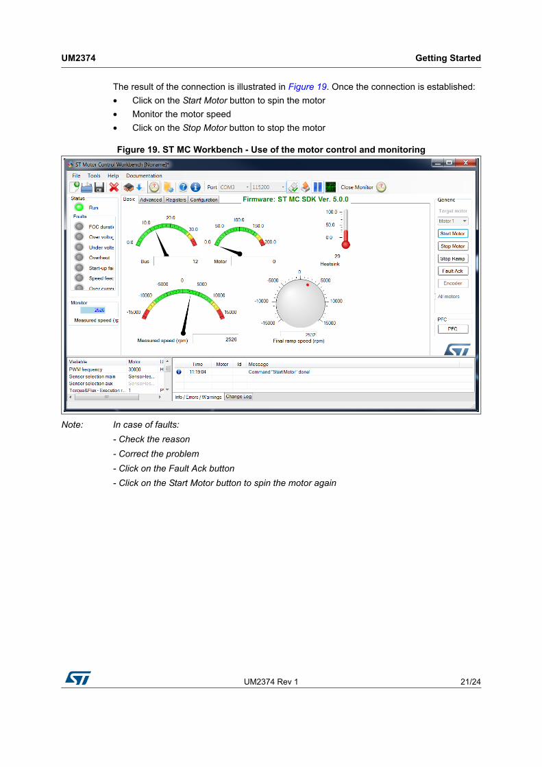
The result of the connection is illustrated in Figure 19. Once the connection is established:
• Click on the Start Motor button to spin the motor
• Monitor the motor speed
• Click on the Stop Motor button to stop the motor
Figure 19. ST MC Workbench - Use of the motor control and monitoring
Note: In case of faults:
- Check the reason
- Correct the problem
- Click on the Fault Ack button
- Click on the Start Motor button to spin the motor again
Precaution of use and restrictions UM2374
22/24 UM2374 Rev 1
4 Precaution of use and restrictions
The motor profiling algorithm is intended for rapid evaluation of the ST MC solution. It can be used to drive any three-phase PMSM without any specific instrument or special skill.
Although the measurements performed are not as precise as with a proper instrumentation, ST Motor Profiler measurements are optimized (green color in Figure 7: ST Motor Profiler - Measurement results on page 12) when:
• The stator resistance is greater than 1 Ω
• The stator inductance is greater than 1 mH
Moreover, it is important to choose the appropriate HW according to the characteristics of the motor. For instance, the maximum current of the motor should match the maximum current of the board as closely as possible.
The ST Motor Profiler may be used only with compatible STMicroelectronics evaluation boards.
Warning: Use the ST Motor Profiler tool to refer to the list of supported systems.
UM2374 Rev 1 23/24
UM2374 Revision history
23
Revision history
Table 2. Document revision history
Date Revision Changes
6-Mar-2018 1 Initial release.

UM2374
24/24 UM2374 Rev 1
IMPORTANT NOTICE – PLEASE READ CAREFULLY
STMicroelectronics NV and its subsidiaries (“ST”) reserve the right to make changes, corrections, enhancements, modifications, and improvements to ST products and/or to this document at any time without notice. Purchasers should obtain the latest relevant information on ST products before placing orders. ST products are sold pursuant to ST’s terms and conditions of sale in place at the time of order acknowledgement.
Purchasers are solely responsible for the choice, selection, and use of ST products and ST assumes no liability for application assistance or the design of Purchasers’ products.
No license, express or implied, to any intellectual property right is granted by ST herein.
Resale of ST products with provisions different from the information set forth herein shall void any warranty granted by ST for such product.
ST and the ST logo are trademarks of ST. All other product or service names are the property of their respective owners.
Information in this document supersedes and replaces information previously supplied in any prior versions of this document.
© 2018 STMicroelectronics – All rights reserved