Embed Size (px)
Citation preview

UNCLASSIFIED
.„270 810 Reproduced
hu Ute
ARMED SERVICES TECHNICAL INFORMATION AGENCY ARLINGTON HALL STATION ARLINGTON 12, VIRGINIA
UNCLASSIFIED

NOTICE: When government or other drawings, speci- fications or other data are used for any purpose other than in connection with a definitely related government procurement operation, the U. S. Government thereby incurs no responsibility, nor any obligation whatsoever; and the fact that the Govern- ment may have formulated, furnished, or in any way supplied the said drawings, specifications, or other data is not to be regarded by implication or other- wise as in any manner licensing the holder or any other person or corporation, or conveying any rights or permission to manufacture, use or sell any patented invention thai; may in any way be related thereto.

,,,
THIS DOCUMENT IS BEST QUALITY AVAILABLE. THE COPY
FURNISHED TO DTIC CONTAINED
A SIGNIFICANT NUMBER OF
PAGES WHICH DO NOT
REPRODUCE LEGIBLY.

Cl-<3 J
NOX NASA TN D-999
OS o> OS
I
Q
< CO
<
f I—»
X
*
r
O r
■'.. .. *
TECHNICAL NOTE
D-999
COEFFICIENTS OF FRICTION AND WEAR CHARACTERISTICS
FOR SKIDS MADE OF VARIOUS METALS ON CONCRETE,
ASPHALT, AND LAKEBED SURFACES
By Robert C. Dreher and Sidney A. Batterson
Langley Research Center Langley Air Force Base, Va.
NATIONAL AERONAUTICS AND SPACE ADMINISTRATION
WASHINGTON January 1962
1

IE
NATIONAL AERONAUTICS AND SPACE ADMINISTRATION
TECHNICAL NOTE D-999
COEFFICIENTS OF FRICTION AND WEAR CHARACTERISTICS
FOR SKIDS MADE OF VARIOUS METALS ON CONCRETE,
ASPHALT, AND LAKEBED SURFACES
By Robert C. Dreher and Sidney A. Batterson
SUMMARY
An investigation was made to obtain the coefficients of friction .and the wear characteristics for skids made of various metals. Simu- lated landings and slideouts were made at forward speeds up to l8o feet per second on concrete, asphalt, and lakebed surfaces. The results indicate that coefficients of friction developed by wire-brush skids and some of the softer metal skids compare favorably with those devel- oped by braked wheels with rubber tires; however, the wire-brush skids and the skids made of the softer metals showed the greatest amount of wear.
INTRODUCTION
One of the problems to be considered for recoverable reentry vehi- cles as well as conventional aircraft is that of providing a safe landing. A landing gear must provide airplane stability during the landing run and be capable of stopping the aircraft within a reasonable distance. Temperature, weight, and reliability are some of the factors affecting the design of a satisfactory landing gear. The environmental temperatures reached by a reentry vehicle are fairly high and the tem- peratures reached during braking of conventional aircraft are becoming more critical as higher energy systems are developed. The conventional braked wheel with a rubber tire is becoming less suitable for high- energy aircraft and impractical for vehicles which reach high tempera- tures during reentry. One solution to the problem of high temperatures produced during braking of conventional aircraft is to Increase the size of the brakes. Some designs also provide for cooling or dissi- pating the heat generated during braking. However, most of these solu- tions necessarily increase the weight of the vehicle. In some cases the weight penalty would be objectionable, especially in a reentry vehicle. These various limiting factors have stimulated investigations of alternate types of landing-gear design.

One of the most desirable alternate designs uses skids for the ground-contact members. They can be fabricated from materials capable of withstanding the environment of a reentry vehicle and may provide suitable stability and deceleration during the landing run or slideout. In the past, skis have been used on conventional aircraft for opera- tions from snow or water and appear to be suitable for these operations. More recently, skids have been used on the X-15 hypersonic research vehicle. This vehicle will at least approach many of the reentry and landing problems associated with high-energy vehicles. Skids have also been used on the X-2, an experimental hypersonic aircraft, and on recov- erable drones and missiles. The use of skids on these vehicles has been L limited mostly to landings on a dry lakebed several miles long, and decel- 1 eration and skid life have proved to be adequate under these conditions. 3
If Reentry vehicles may not always have a long dry lakebed for 6
landings and may be required to use available landing strips which may be as short as 5*000 feet and consist of several types of landing sur- faces. Therefore, if skids are to be used in a landing-gear design, they must be developed so that they are capable of landing on all types of conventional runway surfaces.
Studies of the development of such skids were made at the Langley landing-loads track. Simulated landings and slideouts using skids fabricated of various metals were made on concrete, two types of asphalt, and a simulated lakebed surface. A limited number of these landings were made on wet concrete and asphalt surfaces and also with the skids preheated to approximately 1,000° F above the ambient temperature. It is the purpose of this paper to present the results obtained from these investigations.
APPARATUS AND TEST PROCEDURE
Simulated landings and slideout tests were made with the skids by using the carriage at the Langley landing-loads track. This carriage is propelled to the desired horizontal velocity by means of a hydraulic jet catapult. The operation of this facility is described in refer- ence 1. A drop linkage was attached to the carriage as shown in fig- ure 1 and was similar to that described in reference 2. A fighter air- plane nose landing gear was attached to the drop linkage, and a fixture to accommodate shoe skids was mounted on the axle of the nose gear (fig. l). Skids fabricated of different materials were fastened to this fixture as shown in figure 2. The carriage was propelled along the runway at various forward speeds, and at a preselected point the

skid was allowed to land on the runway and slide for 400 to 600 feet. The skid fixture was free to move several degrees in the pitch and roll directions but was restrained in the yaw direction.
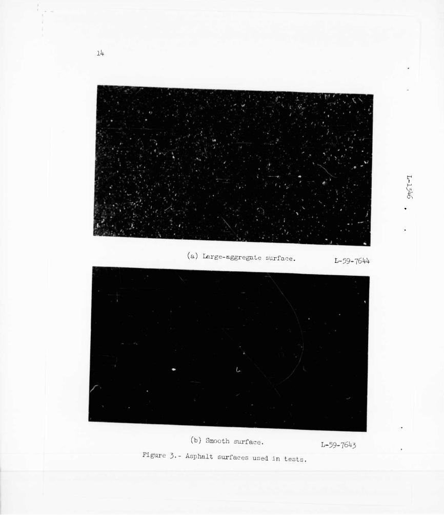
The static vertical load on the skids was 2,150 pounds. Simulated landings and slideouts were made at forward speeds up to l8o feet per second on concrete, asphalt, and simulated lakebed surfaces. The con- crete surface was similar to a standard concrete runway. The asphalt surface was 600 feet long; the first 400 feet had a smooth sand finish and the remaining 200 feet had a considerably rougher finish, having
L been surfaced with a mix containing relatively large stone aggregate. 1 The aggregate for the smooth asphalt was no larger than that which could 2 pass through a No. 10 sieve. The aggregate for the rough asphalt was % such that 100 percent could pass through a 1-inch sieve, 95 to 100 per- 5 cent through a 5/^-inch sieve, 60 to 80 percent through a 3/8-inch sieve,
4o to 60 percent through a No. h- sieve, 20 to ko percent through a No. 10 sieve, and 3 to 10 percent through a No. 80 sieve. A comparison of the two surfaces is shewn by the photographs in figure J.
The simulated lakebed surface shown in figure 4 was approximately 1+O0 feet long, 3 feet wide, and 3 inches deep. Wood retaining members were fastened to the concrete surface along the sides; of the bed. The lakebed material was obtained locally and was compacted by wetting and rolling until it was similar to a dry lakebed. The test to determine when the surface was compacted sufficiently was made with a 15-pound steel ball which-was 5 inches in diameter. The ball was dropped onto the simulated lakebed from a height of 7 feet. If the indentation left by the ball was 3 inches wide or less the bed was considered to be com- pacted sufficiently for testing. A photograph of an indentation in the lakebed surface made during a test is shown in figure 5-
The majority of the tests made on the concrete and asphalt surfaces were made with the surfaces dry; however, a few tests were made with the surfaces wet. The depth of the water was such that only the highest irregularities of the surfaces protruded above the water. On the con- crete surface some of the puddles reached a depth of 0.3 inch; however, the asphalt surface had fewer irregularities and the puddles on this sur- face did not exceed approximately 0.1 inch.
A few of the tests were made with the skids preheated to approxi- mately 1,000° F above the ambient temperature. The method of heating the skids is shown in figure 6. A burner consisting of a number of openings in a tube, which was the length of the skids, was connected
, to a pipe from a standard oxygen-acetylene welding unit. The burner was placed under the skid and ignited. When the skid had reached the desired temperature as determined by a thermocouple attached to the skid, the burner was withdrawn and the test was made. Three thermo- couples were mounted on the skid at the positions shown by the sketch

in figure 7- Thermocouples were mounted on the center line of the skid near the ends and at the center. As shown by the sketch, the thermo- couples were placed on the upper surface of the skid.
The skids were weighed before and after each landing test in order to determine the amount of wear.
INSTRUMENTATION
The instrumentation was very similar to that described in refer- ence 2. Accelerometers were used to measure accelerations of the upper and lower masses in the vertical and drag directions. A slidewire indi- cated the nose-gear strut deflection, and a load cell mounted in the drag link of the nose gear gave a measurement of the drag load. By using the measurements obtained from these instruments and the method described in reference 2, the vertical and drag loads on the skid were determined. From these loads the coefficient of friction between the skid and the runway surface was determined. The output of the thermo- couples was recorded directly by an oscillograph.
L 1 3
TEST SPECIMENS
In this investigation thirteen skids were tested. The contact sur- face of the skids was approximately k inches wide and 2h inches long. The wearing surface of the following skids was about l/k inch thick: Beryllium copper, nickel, 1020 steel, 301 stainless steel, and titanium. The skids of soft cermet, hard cermet, tungsten carbide, molybdenum, and columbium had the metal flame-plated on " base of Inconel X. One skid consisted of a nickel-sheet shoe O.OoO inch thick with a steel mesh between the shoe and the skid fixture which allowed the contacting sur- face to be more flexible as it slid over the runway surface.
The two skids shown in figure 6 have wire brushes as the contacting surfaces. The wire is made of 321 stainless steel having an ultimate tensile strength of 293,000 pounds per square inch at room temperature. This material is being used in aluminum mills at temperatures up to 1,000° F. One skid has a wire trim length of 2 iv :hes and the other a 3-inch trim length.
RELIABILITY OF TEST RESULTS
Because of the equipment used for these tests it was necessary to make each test over the same section of runway. In order to investigate

the effect of repeated slideouts over the same portion of runway surface, a 1020 steel skid was selected as a control. It was the first skid tested and was retested when inspection of the landing surface indicated significant changes. Figure 9 shows the effect of the coefficient of friction obtained during these tests of the 1020 steel skid on concrete and both types of asphalt surface. The numbers by each data point indi- cate the total number of runs that had been made on each surface when that particular data point was obtained. It can be seen that for all surfaces the earlier runs yielded higher friction coefficients, but the actual difference is small. Data indicate that this effect is somewhat greater for skids made of metals softer than steel and less for skids of the harder materials.
RESULTS
Coefficient of Friction
When a skid slides over a surface, junctions at the surfaces are formed and sheared and, in addition, the harder surface asperities plow out the softer material. These two actions, shearing and plowing, are the chief factors producing the resistance which determines the coeffi- cient of friction.
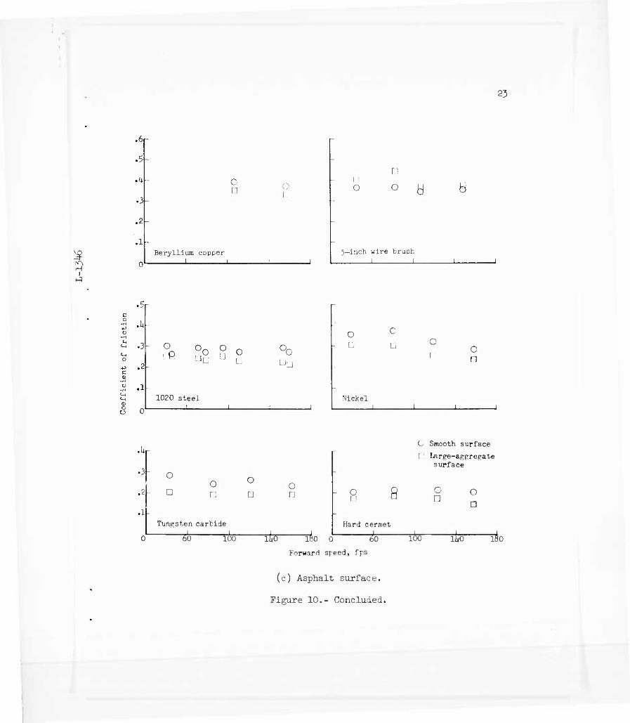
The values of the coefficient of friction obtained at various forward speeds during simulated slideouts on dry concrete, asphalt, and simulated lakebed surfaces for each of the skids used in this test are shewn in figure 10. The values obtained from tests of the skids on the concrete surface are shown in figures 10(a) and 10(b). Values obtained with the copper, 1020 steel, and J-inch-wire-brush skids on a lakebed surface are also shown in figure 10(b). The values of the coefficient of friction obtained on the asphalt surfaces are shown in figure 10(c). In this ficure the circular test-point symbols represent the values obtained on the smooth asphalt surface, whereas the square symbols represent those obtained on the large-aggregate asphalt surface. It can be seen that, for the most part, the scatter of the data is small.
Skids on concrete surf-ice.- The variation of the average coefficient of friction with forward speed during slldeout for the skids on a dry concrete surface is shown in figure 11. These curves were obtained by fairing a line through the data points shown in figures 10(a) and 10(b). Consequently, the coefficient of friction at a given forward speed is an average value. Figure 11 shows that the coefficient of friction is higher for the skids made of the softer metals .and the wire-brush skids. The coefficient of friction decreases with an increase in forward speed for all skids tested. However, this decrease is larger for the skids

made of the softer metals than it is for the skids made of harder metals and for the wire-brush skids.
Skids on asphalt surface.- Figure 12(a) shows the variation of the coefficient of friction with forward speed for several skids on the smooth asphalt surface and figure 12(b) gives the variation on the large- aggregate asphalt surface. These curves were obtained also by fairing a line through the data points shown in figure 10(c). This figure shows again that the coefficient of friction is higher for the skids made of the softer metals and the wire brushes and that the coefficient decreases with forward speed. It can also be seen from figure 12 that the coeffi- cient of friction for the solid skids Is higher on the smooth asphalt surface than on the large-aggregate surface, whereas the reverse is indi- cated for the wire-brush skid.
Skids on lakebed.- Difficulties in maintaining a stable lakebed runway limited the number of tests made on this surface. The data obtained using 1020 steel, copper, and wire-brush skids are shown in figure 13. It can be seen that the coefficient of friction of the copper skid on this surface is about the same as that of the steel skid at approximately ko feet per second; whereas, it was much higher on the concrete surface. This result suggests that for a solid shoe-type skid the ccefficient of friction on a lakebed surface is independent of the skid material. It is believed that with solid skids all of the resist- ance is produced as the skid shears and plows the lakebed surface, with little or no shearing or plowing taking place on the skid.
The wire-brush skid developed a coefficient of friction of about 0.6 which was the highest obtained during the tests. Here, too, the lakebed produces practically all the resistance. The wire bristles were observed to penetrate the lakebed to a greater depth than the solid skids. This increased plowing of the lakebed is much greater and produces the higher coefficient of friction.
Effect of runway surface.- The effect of the runway surface on the coefficient of friction for several skids is shown in figure Ik. The variation of the coefficient of friction with forward speed on a con- crete surface, a smooth asphalt surface, and a large-aggregate asphalt surface is presented. The variation obtained with the 1020 steel skid on a simulated lakebed surface is also shown. It can be seen from this figure that the coefficient of friction for the copper skid is higher on the concrete surface than on either of the asphalt surfaces, and that for the nickel and 1020 steel skids the coefficient on the concrete sur- face is about the same as that on the smooth asphalt surface and higher than the value on the large-aggregate surface. For the skids made of harder metals, tungsten carbide and hard cermet, the coefficient of friction on the concrete surface is less than the coefficient obtained on the smooth asphalt surface but higher than that on the large-aggregate

asphalt surface. Figure lU also shows that the coefficient of friction obtained with the 3-inch-wire-brush skid on the concrete surface was about midway between that obtained on the two asphalt surfaces. In addition, this figure shows that the coefficient of friction obtained for the 1020 steel skid was higher on the lakebed surface than on any of the other surfaces. At the higher forward speeds the coefficient of friction for this skid on the lakebed is approximately 0.1 higher than it is on the large-aggregate asphalt surface and at the lower forward speeds it is about 0.2 higher.
Effect of skid temperature.- A reentry vehicle will reach very high temperatures as it enters the earth's atmosphere. In order to simulate the temperature conditionr expected to exist during landing of a reentry vehicle equipped with skids, a limited number of tests were made with skids preheated to approximately 1,000° F above ambient temperature. Simulated slideouts were made at various forward speeds with the 1020 steel and nickel skids on concrete and asphalt surfaces and with the hard cermet skid on the asphalt surfaces. The results of these tests are shown in figure 15- It can be seen from the figure that values of the coefficient of friction obtained on the concrete surface with the 1020 steel skid and the nickel skid at elevated temperatures in general are lower than the average values obtained with the skids at ambient temperature. On the asphalt surfaces there appears to be a tendency for the values of the coefficient of friction obtained with the 1020 steel, nickel, and hard cermet skids at elevated temperatures to be higher than the average values obtained with the skids unheated. In addition, for the heated skids, the values obtained on the smooth asphalt surface were about the same as those obtained on the large-aggregate asphalt surface. Forward speed appeared to have less effect on the coef- ficient of friction with the skids at elevated temperatures.
Time histories of the temperatures measured by thermocouples on the 1020 steel skid during two slideouts on the asphalt surface are shown in figure l6. Thermocouples were mounted on the upper surface near the front, center, and rear of the skid. The three curves in the upper part of the figure represent the temperatures obtained at the three positions along the skid during a slideout at 120 feet per second with the skid preheated to approximately 1,000° F above the ambient temperature. The zero value on the temperature scale of this figure is the ambient tem- perature. It can be seen that the temperatures remained fairly constant throughout the test. The curves in the lower part of the figure represent the temperatures obtained during a slideout on the asphalt runway at l6o feet per second with the 1020 skid unheated. These curves show that heat is generated as the skid slides along the runway. In this particular test the rise in temperature was 110° at the position near the rear of the skid. It should be pointed out that the thermocouples measured the tem- peratures on the upper surface of the skid; hence, the values of the

8
temperatures were determined by the amount of the heat that had flowed * from the contacting surface to the thermocouples. The temperatures at the contacting surface were probably much higher. Reference 3 shows that for surfaces sliding under even moderate loads and at moderate speeds the surface temperatures will reach very high values. The three symbols in figure l6 are values of the temperatures measured at the three positions along the skid several minutes after the test. It can be seen that the temperatures have continued to increase since more of the heat has had time to flow from the contacting surface to the thermocouples..
Since the asphalt surface was in a hot mix condition when it was L laid, it was believed that a heated skid might affect this type of sur- 1 face. This was investigated by hearing the 1020 steel skid to approxi- 3 mately 1,000° F above the ambient temperature and placing it on the k asphalt surface with a vertical load of 2,150 pounds. The skid was then 6 pushed along the surface for a few feet. It was found that the heated ► skid had no significant effect on the asphalt surface. The coefficient of friction obtained during the push run was approximately the same as that obtained when the skid was pushed in a similar manner at ambient temperature.
Effect of wet runway.- In order to obtain some indication of the effect a wet runway surface would have on the coefficient of friction, tests were made with the runway surfaces wet. These tests consisted of one slideout each with the copper, nickel, 1020 steel, stainless- steel, and titanium skids on the concrete runway and three slideouts with the 1020 steel skid on the asphalt surfaces. Figure 17 shows the results of these tests. The lines In the figure represent the variation of the coefficient of friction with forward speed with the skids on a dry sur- face. The test-point symbols represent values of the coefficient of friction obtained with the runway surface wet. It can be seen from the figure that the coefficients of friction obtained with the copper, 1020 steel, and stainless-steel skids on the wet concrete surface are somewhat lower than the average coefficients obtained on the dry con- crete surface, while that obtained with the titanium skid is higher. The coefficient of friction obtained with the 1020 steel skid on the wet smooth asphalt surface is about the same as that obtained on the dry smooth asphalt surface. However, the coefficient obtained on the wet large-aggregate surface is higher than the coefficient obtained on the dry large-aggregate asphalt surface. In addition, the data obtained on the asphalt surfaces indicate that the coefficient of friction for the 1020 steel skid is about the same on the wet smooth asphalt surface as it is on the wet large-aggregate surface.

t Wear of Skids
Wear of the skid is caused by the shearing of asperities from its surface and the plowing out of the skid material by the surface over which it slides. The speed of sliding, the strength of the skid material, a.nd the strength of the surface material are some of the factors which affect the amount of skid wear. As mentioned previously, the amount of wear of the skids used in this investigation was determined by weighing the skids before and after each test.
L Figure 18 shows the wear in pounds per foot of sliding for several ]_ solid-metal skids on concrete and asphalt surfaces at various forward x speeds with a static vertical load of 2,150 pounds. The number near ij. each data point represents the total number of tests that had been made g on each surface at the time that the particular data point was obtained.
It can be seen that the wear was greater during the first tests than during later tests. The general trend of the data indicates that the wear increases with forward speed. This effect is more pronounced with the skids made of the softer metals. As in the case with the coefficient of friction, the forward speed has little effect on the wear of skids made of the harder metals. No trend was indicated by the data obtained with the wire-brush skids.
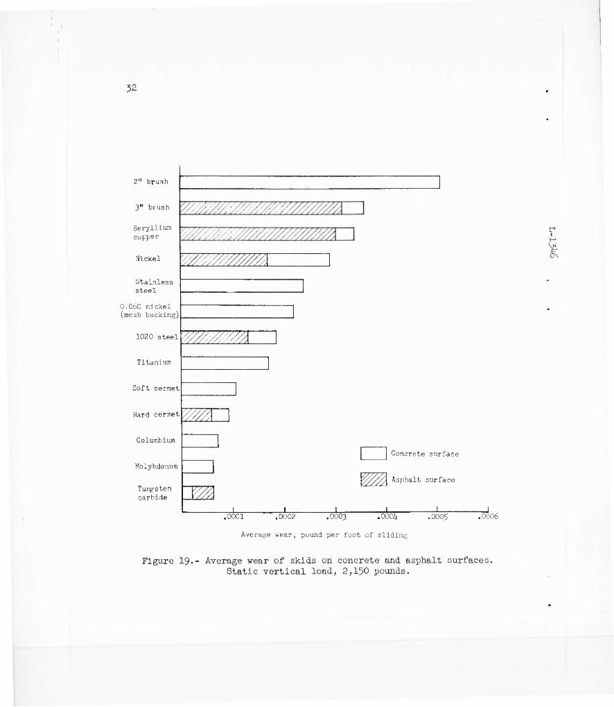
The relative wear of the skids in pounds per foot of sliding obtained during tests on concrete and asphalt surfaces is shown by the bar graph in figure 19- The values of the amount of wear for each skid are the average values obtained from all the tests made on the skid. Therefore, this bar graph is indicative only of the amount of wear per foot of sliding since the effect of such variables as surface roughness and sliding speed is included in the values. The forward speed in these tests ranged from approximately ho to l80 feet per second. Wear of the skids on the asphalt surface was a result of sliding over both the smooth and the large- aggregate asphalt surfaces. This figure shows that the wire-brush skids and the solid skids made of the softer materials had the highest average wear per foot of sliding. The amount of wear decreased as skids made of the harder metals were used. It can be seen that the wear was higher on the concrete surface than on the asphalt surface for all skids except the tungsten carbide skid.
Figure 20 gives an indication of the amount of wear to be expected for each skid for various sliding distances on concrete surfaces whereas figure 21 gives the wear to be expected for several skids on asphalt sur- faces under conditions similar to those described in this report. In these figures the average value of the wear per foot of sliding for each skid was used to obtain the curves. The curves are indicative of the relative amount of material which would be necessary for various slide- out distances for each of the materials tested.

10
Skids as Brakes
Wheel brakes are relied upon to provide the major portion of deceleration during landings of most present-day aircraft. However, with increasing landing speeds and weights the kinetic energy to be absorbed by the brakes becomes appreciable. Auxiliary deceleration devices such as parabrakes and thrust reversers have been provided on some aircraft in order to ease the load on the wheel brakes and to keep the landing-run distances within the limits of existing runways. The data obtained during this skid investigation indicate that some type of skid could be capable of producing a retarding force that would compete favorably with wheel brakes in providing the major share of the decelera- tion required during landing runs. Wheel brakes equipped with antiskid devices are capable of developing an average coefficient of friction of 0.3 to O.h- during landing. It can be seen in figure 11 that the wire- brush skids as well as some of the softer metal skids are capable of producing coefficients of friction which compare favorably with those developed by the braked wheel and rubber tire. Although conventional wheels and brakes are necessary for taxiing, take-off, and directional stability during the landing run, it appears possible that skids could be utilized to provide a significant amount of deceleration during the landing.
CONCLUSIONS
An investigation has been made to determine the coefficients of friction and wear characteristics for skids made of various metals on concrete, asphalt, and lakebed surfaces. The principal conclusions indicated by this investigation are as follows:
1. Wire-brush skids and skids made of the softer metals are capable of developing coefficients of friction that compare favorably with those developed by a braked wheel with rubber tire.
2. For a solid metal skid the coefficient of friction on the lake- bed surface appears to be independent of the skid material.
jj. The wire-brush skids and the skids made of the softer metals showed the greatest amount of wear. The amount of wear was greater on the concrete surface than on the asphalt surface.
Langley Research Center, National Aeronautics and Space Administration,
Langley Air Force Base, Va., October 18, 196I.

11
REFERENCES
1. Joyner, Upshur T., and Home, Walter B. : Considerations on a Large Hydraulic Jet Catapult. NACA TN 3203, 195^. (Supersedes NACA RM L51B27.)
2. Dreher, Robert C., and Batterson, Sidney A.: Landing and Taxiing Tests Over Various Types of Runway Lights. NACA RM L58C28a, 1958.
L 3- Bowden, F. P., and Tabor, D.: The Friction and Lubrication of Solids. 1 The Clarendon Press (Oxford), 195^ • 3 k 6

12
0\ --t
: i
c\ ITS
I »1
i (Q
a 0 H
I M d
•H
§
H M a
a o
O
o 1 II
H
•H <H
•H
15
CD bi) cd
•H
"1 ■J •H
cd cd a> u bO -P
q ■A
9
ca o
0)
a
i H
0\

I
I 1
13
H
fixture
_, L-59-1698.1 Figure 2.- Shoe skid attached to skid fixture for testing.
Ik
(a) Large-aggregate surface L-59-7644
(b) Smooth surface.
Figure 3.- Asphalt surfaces used in test;
L-59-76^3

15
öS H
i
i
w ■P w (U
a ■H
-1 D to a u o
4 4
T3
cj
+) d
I 03
I
-1
I

16
V \R
I w CT\ (II lT\ .p
o
«3 I o Ü
a
■d 0) w 3
CJ p to
CJ d H LO
•Ö , D fi V
H
a o
p
g H
I
II

2E
17
t H
i
CO
TJ •H AJ M
TO Ö
■H P d tu
XI
0 '" o
-p 0) S
i
VO
<1)
5

18
forward
Thermocouple —-
Skid fixture
-ca-
ll" — 11"
2k"
Side view
kid
l/li" ^
Thermocouple
Cross section
Figure 7.- Sketch showing locations of thermocouples on skid.

L9
3 H
I
i ON
tfl -P eg
P
ö to
w
•H .■>; ra
ra
I t)
d
/

20
c o
I.
G
«H m c C5
.3-
.2
.1
0
■3r
.2-
.1
.14
.3
.2-
.1
20
Concrete
8 O
53 00 7ß l 79
<§>0 !
0 50 19
- Sfa o $5
0 77
(J o
1 I I i . I i —1
Larpe-apprepate asphalt
1 19 O O
2 20 o o
3 O
21
O
Smooth asphalt
1 0 O
19
O 20 0
3 O
21 O
ao 60 80 TOO 120 iao Forward speed, fps
O O 22
0 22 o
160 180
T
Figure 9.- Effect of landing-surface wear on the coefficient of friction for 1020 steel skid.

.'1
H i
•3
0
o o
o
2—inch wire brush I i_
o
^o & o o
1020 steel I L
O o.
0 cP c o o o
Stainless steel i 1 l ... _. __i
r ° o
o o c V
Nickel , 1 1 1 -. _J
a o U
o o C
c
Tungsten carbide . . I 1 l . . 1
- G
Hard cermet
• 3
.2
oo
Titanium
?0 60
O c o c
Molybdenum i_
100 liiO ~180 20 ""'SO
Forward speed, fps
G O O
100 1W ao
(a) Concrete surface.
Figure 10.- Values of the coefficient of friction at various forward speeds for several skids on concrete, lakebed, and asphalt surfaces

22
? •3-
.2-
c o
.1
J .61-
.5,
1
0.6 nickel with mesh backir
>
o
Beryllium copper 1 L_
'■"-' C
o
Soft cermet
O '-
3-inch wire brush
c o
tr1
1 1 H
.7
.6
.5-
.I4-
• 3-
.2-
.1
0L_ 20
O
Columbium 1
60
O
100
C
~Thö~
L.-
Lakebed surface
O
O o <
Q 3—inch wire brush
O 1020 steel
A Berylli
180 20 60
forward speed, fpb
100
um copper 1 1[|0 180
(b) Concrete and lakebed surfaces.
Figure 10.- Continued.
;J3
I
•6r .5-
,u-
• 3-
.2-
.1-
o
C I !
Beryllium copper I I
O I-
0
n o b
3—inch wire brush
h
c o
•H
<u p
.5r
.it-
.3
.2
J
0
o °o ,° o ■JL U L:
1020 steel
o - Ü
c u c
0 [ f i
Nickel 1 i I
• 3-
.2-
.1-
0
□ 0 rj
Tungsten carbide
0 Tfr -±-
0 11
o
100 rfe-
V o □ 8
180 0
Forward speed, fps
Hard cermet
&—
C Smooth surface
I Large-aggregate surface
C n o
n
100 ll<0 180
(c) Asphalt surface.
Figure 10.- Concluded.

2k
<V i. 01 I |
■3 I O | i R C\j ) 3 O /, •H rH / -2
I' E
r 1
\/ 1 o [ '
( I
(
1
Q
0)
C
< . 3
-p a- E i. c u T-
a :::
a o a
U 1» > V CO
SH
0 »H
d i- ■u p-, w
rd 3
o \4
c 0 *J o
•H In
«in
II •H o •H tu -•-, V J o
0 c o
•H
d
D U id in
3 CO
0) ■p <U ?H U c u
t-1
I H
uof^oTJ.} .jo ^U9TOT,fjaoo aSBjaAV

25
3 RS H
■ Nickel
3-inch wire brush
1020 steel
Tunpsten carbide
Hard cermet
Beryllium copper
.11
3-inch wire brush
Nickel
1020 steel
Tunpsten carbide Hard cermet
20 uo
(a) Smooth asphalt surface.
60 go ~Too
Forward speed, fps
120 lljO 160
(b) Large-aggregate asphalt surface.
Figure 12.- Variation of coefficient of friction with forward speed for several skids on asphalt surfaces.

26
£
(H
S-i
Pi ft
CO 3
,0 It 0
•H u CD h f-i CD ^ •H
d •H g , 1
i-H o
•H
CD a
CO
1-'
CO 0) 1
o
O
O
o
0 n
O T O A
F 1 O c
•H 1
q 3 C. ^
- -3 u r , CL>
Pi ft 0 Ü .
0)
H cd
o -P 3 CM CO CO
c cu 4H &
CD
CT CU H P. CD
<M ft^ CO <D ..... c . p, _ -P
r-t T3 T3 cd cu ?H H a; s 2 ft el
O co T3 CH
^ cd [fl CO
S a c O 00 0
0 o •H Si CO cd T3 > -H id
+5 CO cd
a to
•2 2 o 0
-p n CJ 1
•H 0) h FH
CH -H
O
? ( 3 •H
3 -!
V a
i •
_J° H u
uon3TJJ J° ^"9T3TJJ8oo B

27
Beryllium copper
Runway surface
Concrete
Smooth asphalt
Large-aggregate asphalt — Lakebed
Tungsten carbide
o
1
.?
Nickel Hard cermet
.14
1020 steel 5—inch wire brush
20 " 60 100 LW~ —lBO 20
Forward speed, fps
A 100 lUo lBo
Figure Ik.- Effect of runway surface on coefficient of friction for several skids.

28
.Ur
.2 O O
1020 steel
-c-o- O O
Nickel
I
0) o U
.hr
.2
a H _ _
1020 steel i 1 1
o
Nickel
20 60
Ö —
100 150 180
•Ur
_Q_ _ -O- -a -
20
Hard cermet 1_
"60 100 1U0
Hnheated Heated
O Concrete surface v> Smooth asphalt
large-aggregate asphalt
"180
Forward speed, fps
Figure 15-- Effect of heated skids on the coefficient of friction on concrete and asphalt surfaces.

29
2 SS H
I
B o •H <-> •H OT
a 0>
0 -P i-\ H c ■v tn P. o t3 3 3 C •H a> O Ü O
b. S en
S 1 ■ u i -p i). 1 i 3 £ c IH 1 1
1 1)
-a ■H
o n ; ) n
coc>
3 c •H -U e n a ■ ID <V > -p
to ra
P. ■••
o eg H
Tj ^ U '■'■
■P 1) <n OJ il [.. .: w <u s. ■Ö 0, c a a -.' * 0 a c*
o o 8
Ö o CO
■p CO
0) •p U) G
•H U
•3 us M ia
j0 *^uaxquB aAoqe ajn^Bjeduiej,

50
•6r
Beryllium copper Nickel
1*
c
Si c O
.kr
.?
1020 steel Stainless steel i
.h
Titanium
Dry Wet
O Concrete surface
0 Smooth asphalt
— — D Larpe-aggrefate asphalt
u 20 60 100 1U0 180 20 60
Forward speed, fps
100 iao 180
Figure 17-- Effect of wet runway surfaces on the coefficient of friction for several skids.

31
Concrete surface Asphalt surface
H i
.0006
.0005
.oooU
.0003-
.0002
.0001
0
.000$
.oool»
.0003
.0002
.0001
0
.OOOJjr
.0003
.0002
.0001
0
.0002
.0001
0
.0001
Lit o
o 16 o
Beryllium copper
O
}6 o
0 U7 o
17
0
52 o
-I I I I I I
6 O
5 O
12 O
7 0
37
36 O
63 O
O
1 1. 1 1 1 1 1
Nickel
21
7 O
0 0
1020 Steel
0 11
10 0
20 O
58 53
82 1(1 .
81 57(9
L - . ,
O 080
1 1 1
O
1 1
1 o
o 19 O 20
j 1 Q_
0
21 o
Tungsten Carbide
u6 U5 \Q 1 CJ
23 o 2^
j 1 1 o
25 O
69 Hard cermet
0_ 20
-I .1 ' I I I 100 " lbO 180 20" 60
Forward speed, fps
15 18 -a 1 ifl 1
17 O
100 2,0
JO
9 O
1 ' 1 1 1 1 1 1
5 0
u 0
22 O
26 O
j 1 1
16
rto
Figure l8.- Wear of several skids in pounds per foot of sliding on concrete and asphalt surfaces at various forward speeds. Static vertical load, 2,150 pounds. Number by each data point indicates total number of tests made on each surface when that particular data point was obtained.
y
2" brush
3" brush
Beryllium copper
Nickel
Stainless steel
O.OoO nickel (mesh backing)
1020 steel
Titanium
Soft cermet
Hard cermet
Columbium
Molybdenum
Tunpsten carbide
^ V/A-// J
wm
r/j
Concrete surface
Asphalt surface
.0001 .0002 .0003 .0001,
Average wear, pound per foot of sliding
.0005 .0006
i H
Figure 19-- Average wear of skids on concrete and asphalt surfaces. Static vertical load, 2,150 pounds.

IE
33
3 H
3 ■H
>
o
o
cd
c d - tö
<D o -P ft
<L> fn O O IT\ C H O -> o oj
cd ^
a cd o o
H ra
CJ
CÖ ^ O
-P H U cd D
ü > (D -H IQ +0
cd U -P O 0}
cd w 0) 01 > o
<H a o -p
.ra
o T3 •H -P bO cd c
C H •H W
o CM
0)
•tl

34
10 ■ri 0
•H
> u e a; ti cd
JS
w
o ft o
Eg H CO -\
- CVJ
c i o o
H to
>3 H i-t cd AS ü M -H
-P d £ cd <D R > 1) > CJ 0 •H to +J
cd m •+-> o CO
<H
M # cd w <u <D ^ o
<^i i 0 4J
CO a o ä
-.1 +3 s.-o cd G CJ
•rH 3 T3 •H Ö P-i
•H to
CM
r H
NASA-Langley, 1962 L-13^6

<-> If
c | g oi 8 CO i ! a K
H z uT /i P
01 < 01 u *3j a QCQZ
S» i. .2 -55 ■a -
2 2» - 9 « rt J2 o
1.1 C3- CO cU
. < a x S* 2 K 2 u .§* S Q
< < « O
?1 Lb CO
2 f»< so Oi rt CO oi c t_
Q 0> W
OS < 5 ^
< C1 O i5 id U
Q < CU
gw >, .a
< < m e > J ■§ ° 6h Q « ;
Oi5 t. di
U ^ £ co Q - 1 i
Ä < Co. 2g
o S u. ^ "* w CO CC
CO O
E° w 2 H O
co H
.2 C7J <*
■ago K 5S
33 co . U W e W
rj rt -^ 55 E£
10 -Ö
.2 a • 2 " ~ S 4.
O —
> i
T3 C «US« a
^ ^ « £. 3 ;-J ~ 11 ° cn o M 4i o £ ■— c* CO TJ 'C • - • f - f - « — .^ X3 O
,8 >-. -S 1
U ryl -C J= CO t> - Q.
* ä ffl ? § a, B £ u" <u
c 3 (A :.' B Cg L £ ■_ c
en U -c 0 -_ rt
Oi CO
« -5 cu f T: t,
<£o _ " C Oi >.
01 a
T:^ a s - u
01 J o ► £ ■ 01 01
■a s i
<".§- i: to ^. g o ... o a a m „, * " 41 4Ü _ ^ t3^ O
si £1 &JJ-S § 2-53 = 2 2«« g .c S to ^ ti r: oi
J5 'S ■•- — s -c «
i" » S £ mm QC
5 -F 2 a o * ^ - c- T5 * ~° CO 01 C 4i
■0 Jd » P ■ ~ Cd ,C3 o
CO Si ^ '"
41 _ « c OS ^ -a o> 01 .S CB
-Q CO i
>. »H 01 *H - i 41 < 1 S CO lH « < a CQ x
c co CO O 41 01 - • k
i S 2 .2 -55 ■o -
ST1"
2 k. ^j - V 1 «So
- - c
I jo if)
. < - X .2o
b <
35 S Q
< < ^ z n O
co f-1
T3 O
si
: §g I o —
;^0 1 g E : 5^ i 3 w
el O
|S > J fc. Q O 2 W<
co x C a, 2i2 CO
< 01
CO I-
■a O
Oi *cr oi -c: c»ci i
t a
co H O "> O ^ w 2 2 t,' j
' If
2 2 O
o"
co O Su
W Ü H O
* 3 ■S 3 "- -■ O =(J K = — 5z
. X co . O U G W <J o H -3- co in 55 e£
Sfc« -j» CO CX c.
.a £
a. o _ 1 M >, t u
' _ 41 S
o>
I coo "' be co -c
I C ^H oi
! « O * ' B CO. X ™ Q. « 10 3
2 -c c u
-'S rt 11 ™ •A 41 .
s »■« CO t- a.
A O oi 1—1
Si
E a 2 *- 0j Q> o > > S
lie tn -*- o .► c r ui „
5|l j! h C
a^J C
* J£
§ 2 S
5 S S o
°* T3 ° -C ^
a o « S ^ -
BO .Q jQ
1
<
j4 DO CO
< O en 0)
u >> 0) en
3 en Qi U
- h "5 ^ C 3 0) 0) M ~ — w 7. X 5 Q ~ ■—i
-°£ u ■ H i — £ 01 < i S co k rt <
Q CO 2
Si-"1
— H « c« 2 o
?<^ Ccn n
y2
,ii 2£SQ
- < o ° co M B W
I*3S c Q > J
- Oco < en -s co K . f O) c c_ o U ai oCyf- 1 ^ ,, * w Q3;SCOK 2^0U5 H «EFs ^. O " M n
< « Q Jil Z z /, u h o i
< i
—■ CO co H •u O
. OS t- Q.Oi 1 TT OI £ CO I
" CM'w CD F-i
u 2 p
go "^ i. X
J c U
I* '- < S CO
si
i2 -5 3 ^^ Ä s,
QJ
tC J^ — o cu rt
en u ~1 ■r rt
01 — t,
cu ^ o a* o t, — "J — 3 r c o ?* o
m u O > > en T « 4} « i „ t M
cn o bt CO T3
•" o -g
3 —
S 35 u « — c — c ~ '. ..„ *— «
X 2 7 cy I -^ CO >
c u ■^ (V - ■a
■^. O w TJ iS g . ^- cn
7) "D £ (J «
B ^
§ <u 2 <S ^ ^ £ S ^ *- ^ " et _ * "* L
™ -a ~ _£ a, cn '
rt -c
.2 3 e ^J
co 3
9 -e i «
■v 4
< £ O i O
iCC J » '
CO XJ .o w
u >• 01 _. — c cn
tn -^ cn cn .- cn .a co i < ° Q (•1 <
z fc," « H £ 01 < a a co !- « < Q S3 2
1 (I
C M «] o QJ CJ
•Ü cn t, ■3 « 3
.2 -OT
2« - U rt rt H 0
Is* 4i o co 5 —
a 00
« Ld B W
_ ''<< c Q > J
o, O 2
H < H o s 5 2 co x
u. 2 2 o co <
K
^ — co
: S O w ; S
CO
< 1 >,.2
■" ■£ — J 1 ^*1 ■o S 2 c c a . c 5 t. o <b o t, ,
■a O
co o bL co T: £ a,«
« = "254
cn ca co tc . , Ct CLQ™
1 u ., fc w Q 3 d co a 2 Ü o o g H « E H 2
■o - w e u
< B O U 2 2 ^. O H O
^ cn x: co I 11 G
CO f-1
-2 1 t- —j -:«< c 2 u
1-^ <*
-r ^ ^-1 CU 01 ™ ■3? 41 .
S « -33
CO u CJ
1 C3 CO J ■ i m i»C . j ffl 3 jj
; Oi — l
, 5 ■ *•
'*% I . cn a» o
t« 4 - ; o s 5
i T: o c o cu
33 w
01 S 41
o £ x:
.-'S Oi i
_ U CO j^jz -a S is -a
E, CO ™
g -=
- 3
C £
B 1 ,„ a» » S -c=- o •* -* ;8-i
- co oi ■*= : -a ^ co
33 -i p -.^ C c : co j2 ^
< z
1 (I
s <
I 3

_^ c « in
<i Bf 1 lit, ü är s ■ a 3 £ — ~ c 0> s C 5 U TJ OS 23 w C a> - o>
-O ■/: i W ™ 9 Q 2 - 00
*s - o Z <t H
iT in H
1 N
AS.
•c
raft
; ad
s;
5
reh
e at
ter
ASA
Q a z rt ^ o
1.1 ■«—<cr> m
![D]IED SERICES hflIA LCuI · PDF filethis document is best quality available. the. copy furnished to dtic contained x significant number of pages which do not reproduce legibly](https://img.pdfslide.net/doc/110x75/5abe74247f8b9ac0598d2488/died-serices-hflia-lcui-document-is-best-quality-available-the-copy-furnished.jpg)