Embed Size (px)
Citation preview
UNCLASSIFIED
AD 419107
DEFENSE DOCUMENTATION CENTERFOR
SCIENTIFIC AND TECHNICAL INFORMATION
CAMERON STATION. ALEXANDRIA, VIRGINIA
UNCLASSIFIED
NOTICN: toen overnsent or other dravings, speci-fications or other data are used for any purposeother than in connection vith a definitely relatedgovernuent procurement operation, the U. S.Government thereby incurs no responsibility, nor anyobigation vthtsoever; and the fact that the Govern-mnt my have fozufated, furnished., or In any waysupplied the said dravings, specification., or otherdata is not to be regarded by implication or other-vise as in any anner licensing the holder or anyother person or corporation, or conveying any rigbtsor permission to imao!ctr, use or sell anypatented Invention that my In any way be relatedthereto.
Y .' ,, ,,p 9 >f, ,
A;' V ~ 'Nt-
AWA
a eg 'i.J1
AAA' -' - "WiT Ns .4
UNCLASSIFIED
MPO-SR- 17-3-205
GROUND ELECTRONICS SYSTEMFOR WS-133B (MINUTEMAN)
FACILITIES DESIGN CRITERIA,
NEW OPERATIONAL LAUNCH
AND LAUNCH CONTROL
FACILITIES
This document supersedes previous material pub-
lished on this subject.
Prepared for
HEADQUARTERSBALLISTIC SYSTEMS DIVISION
AIR FORCE SYSTEMS COMMANDNORTON AIR FORCE BASESan Bernardino, California
Contract Number AF04(694) -261
23 September 1963
Prepared by
SYLVANIA ELECTRONIC SYSTEMSMINUTEMAN PROGRAM OFFICE
63 Second AvenueWaltham 54, Massachusetts
Approved by: __ _E.L. Rich
Submitted by: %UP' 9 2 A('- Approved by: 2Z q:iD.I. Levin M.P. Duffy/
UNCLASSIFIED
T7
MPO-SR- 17-3-205
TABLE OF CONTENTS
Section Page
1 INTRODUCTION ............................... 1-1
1. 1 General ..... ............................ 1-1
2 LAUNCH CONTROL CENTER ................ 2-1
2. 1 Function ........ .................... 2-1
2.2 Architectural ..... ....................... 2-1
2.3 Structural ........ ................... 2-45
2.4 Mechanical ......................... 2-52
2.5 Electrical .......................... 2-53
2. 5. 1 Power ..... ....................... 2-53
2.5.2 Distribution ................... 2-54
2. 5.3 Lighting ...................... 2-54
2. 5.3. 1 Normal Operation ............ 2-54
2. 5.3.2 Survival Lighting ............. 2-55
2.5.3.3 Emergency Lighting .......... 2-55
2. 5.4 Grounding, Shielding and Electro-Interference LCF Grounds ............. 2-55
2.5.5 Conduits ...................... 2-56
2. 6 Communications ..................... 2-57
2. 6. 1 Inside Cable Communications Plant .... 2-57
2.7 Interfaces ....... ........................ 2-572.7.1 Architectural .................. 2-57
2.7.2 Structural ..................... 2-57
2.7.3 Mechanical ..................... 2-57
2.7.4 Electrical ..................... 2-58
2.7.5 Communications ................ 2-58
3 LAUNCH CONTROL EQUIPMENT
BUILDING (LCEB) ....... .................. 3-1
3. 1 Function ........ .................... 3-1
3.2 Architectural ..... ....................... 3-1
iii
MPO-SR- 17-3-205
TABLE OF CONTENTS (Continued)
Section Page
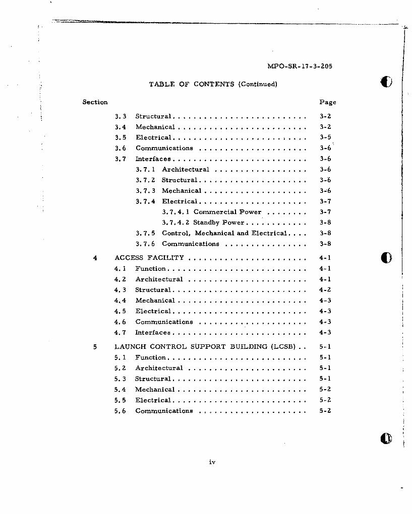
3.3 Structural .......................... 3-2
3.4 Mechanical .............................. 3-2
3.5 Electrical ....... .................... . ... 3-5
3.6 Communications ........................ 3-6
3.7 Interfaces ...... ......................... 3-6
3.7.1 Architectural ... ............... 3-6
3.7.2 Structural ... .................. 3-6
3.7.3 Mechanical ... ................. 3-;6
3.7.4 Electrical ........ ............. 3-7
3.7.4.1 Commercial Power .......... 3-7
3.7.4. 2 Standby Power ............. 3-8
3.7.5 Control, Mechanical and Electrical. . . 3-8
3.7.6 Communications ................ 3-8
4 ACCESS FACILITY ....................... 4-1 U4.1 Function ........ .................... 4-1
4.2 Architectural ..... ....................... 4-1
4.3 Structural ........ ................... 4-2
4.4 Mechanical ...... ......................... 4-3
4.5 Electrical ........ ................... 4-3
4.6 Communications ..................... 4-3
4.7 Interfaces .......................... 4-3
5 LAUNCH CONTROL SUPPORT BUILDING (LCSB) 5-1
5.1 Function ........ .................... 5-1
5.2 Architectural ..... ....................... 5-1
5.3 Structural .......................... 5-1
5.4 Mechanical ...... ......................... 5-2
5.5 Electrical ........ ................... 5-2
5.6 Communications ..................... 5-2
iv

MPO-SR- 17-3-205
TABLE OF CONTENTS (Continued)
Section Page
5.7 Interfaces.................................5-5
5.7. 1 Architectural....................... 5-5
5.7.2 Structural...........................5-5
5.7.3 Electrical...........................5-5
5.7.4 Communications.....................5-5
6 LAUNCHER EQUIPMENT ROOM (LER).............6-1
6.1 Function..................................6-1
6.2 Architectural............................. 6-1
6. 3 Structural................................ 6-1
6.4 Mechanical............................... 6-13
6.5 Electrical................................ 6-13
6.6 Communications...........................6-16
6.7 Interfaces.................................6-16
6.7.1 Architectural........................6-16
6.7.Z Structural...........................6-1616.7.3 Mechanical..........................6-16
6.7.4 Electrical...........................6-16
6.7.5 Communications .. .. .. .. .... ... ... 6-17
6.7.6 Antenna Farm .. .. .. .. .. ... .... ... 6-17
7 LAUNCHER EQUIPMENT BUILDING (LEB) .. .. .... 7-1
7.1 Function .. .. .. .. .. ... ... .... ... ... ... 7-1
7.2 Architectural............................. 7-1
7.3 Structural................................ 7-1
7.4 Mechanical............................... 7-2
7.5 Electrical................................ 7-2
7. 6 Communications...........................7-5
7.7 Interfaces.................................7-5
7. 7. 1 Architectural....................... 7-5
tv
MPO-SR-17-3-205
TABLE OF CONTENTS (Continued)
Section Page
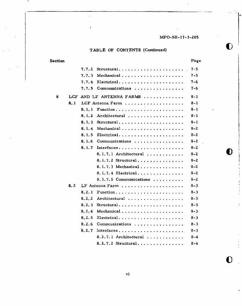
7.7.2 Structural ...................... . 7-5
7.7.3 Mechanical .................... 7-5
7.7.4 Electrical ..................... 7-6
7.7.5 Communications ... ............. ... 7-6
8 LCF AND LF ANTENNA FARMS ............. 8-1
8.1 LCF Antenna Farm ................... 8-1
8.1.1 Function ...................... 8-1
8.1.2 Architectural .. ................... 8-1
8.1.3 Structural ..................... 8-1
8.1.4 Mechanical .................... 8-2
8.1.5 Electrical ..................... 8-2
8.1.6 Communications ................ 8-2
8.1.7 Interfaces ..................... 8-2
8. 1.7.1 Architectural ............ 8-2
8. 1.7.2 Structural ............... 8-2
8. 1.7. 3 Mechanical .............. 8-2
8. 1. 7.4 Electrical ............... 8-2
8. 1.7.5 Communications ........... .. 8-2
8.2 LF Antenna Farm ..... .................... 8-3
8.Z. 1 Function ...................... 8-3
8. Z. 2 Architectural .................. 8-3
8.2.3 Structural ..................... 8-3
8.2.4 Mechanical ...... ................ 8-3
8. Z. 5 Electrical ..................... 8-3
8.2.6 Communications ... ................ 8-3
8.2.7 Interfaces ..................... 8-3
8. Z. 7.1 Architectural ............ 8-4
8.2.7.2 Structural ............... 8-4
vvi
MPO-SR- 17-3-205
TABLE OF CONTENTS (Continued)
Section Page
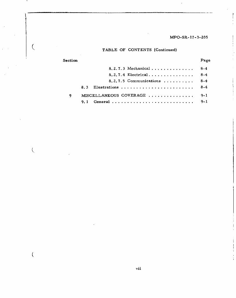
8. 2. 7. 3 Mechanical...................8-4
8. 2. 7.4 Electrical....................8-4
8. 2.7. 5 Communications..............8-4
8. 3 Illustrations...............................8-4
9 MISCELLANEOUS COVERAGE....................9-1
9. 1 General..................................9-1
vii
MPO-SR- 17-3-205
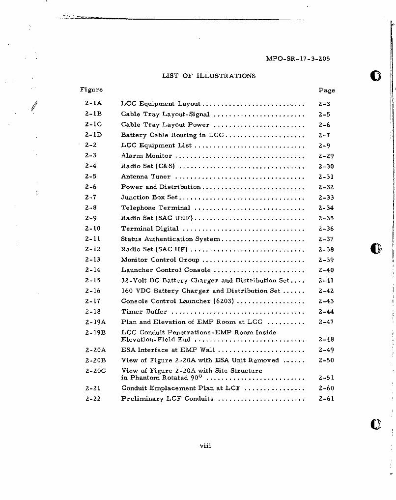
LIST OF ILLUSTRATIONS :.o
Figure Page
7 2-1A LCC Equipment Layout ............................ 2-3
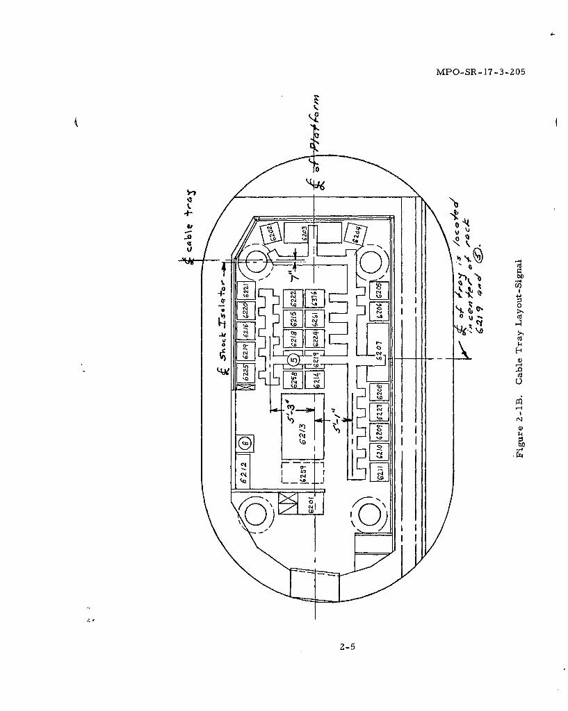
2-lB Cable Tray Layout-Signal .......................... 2-5
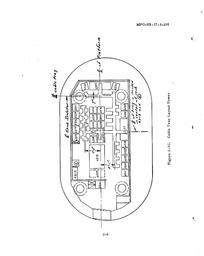
2-iC Cable Tray Layout Power .......................... 2-6
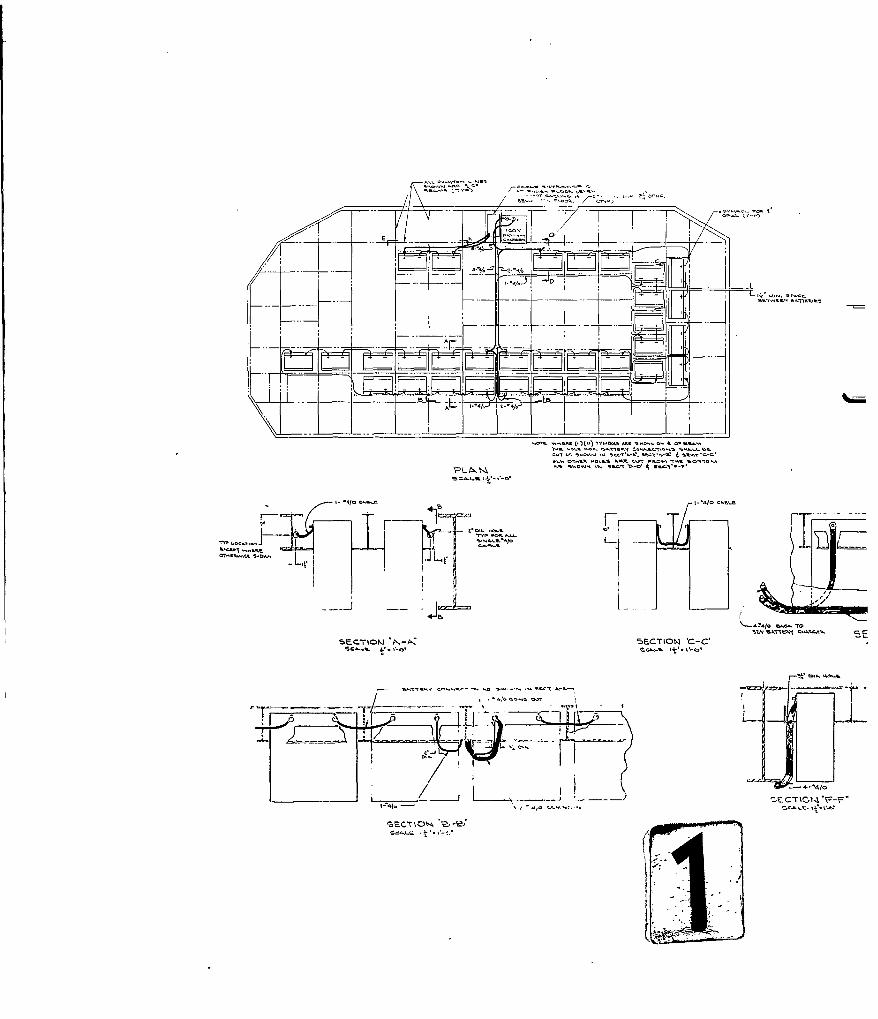
2-ID Battery Cable Routing in LCC ..................... 2-7
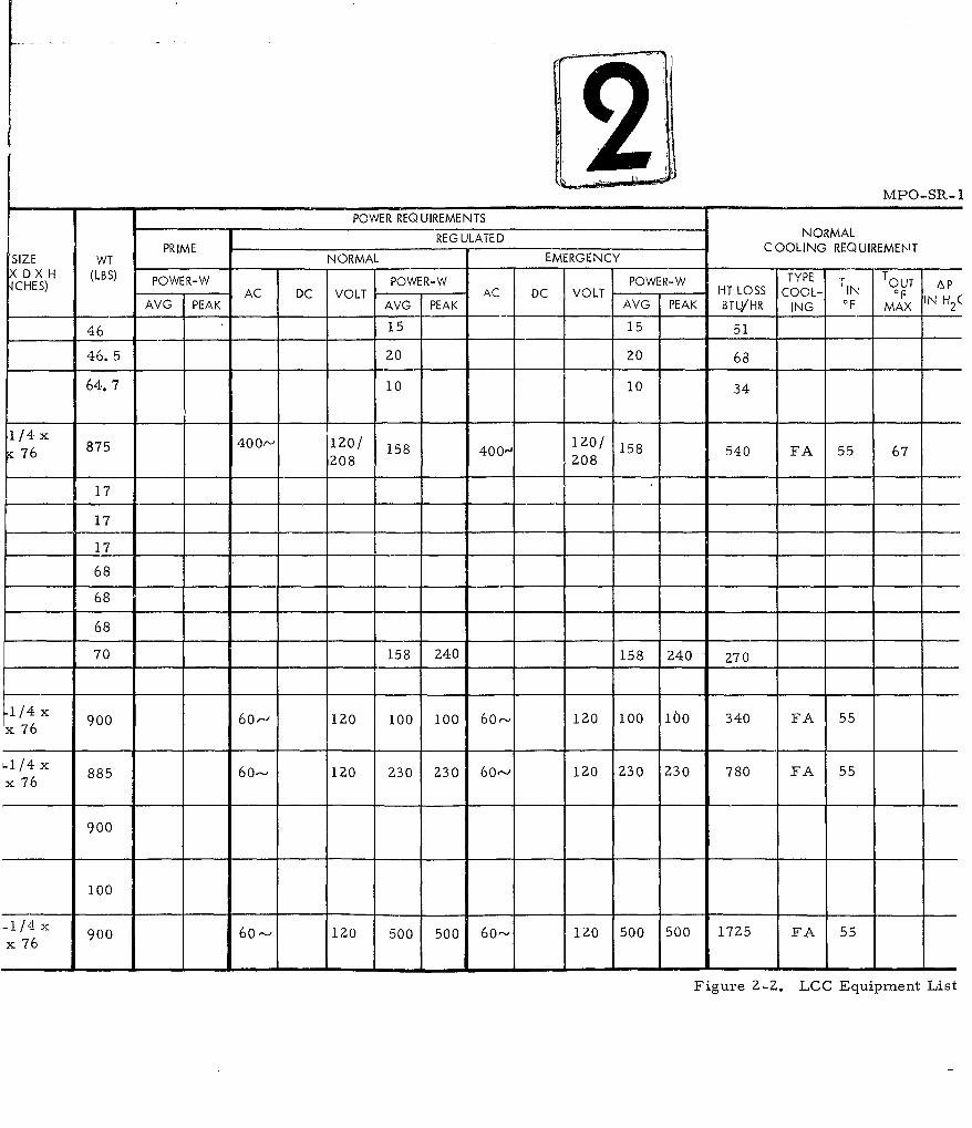
2-2 LCC Equipment List ................................ 2-9
2-3 Alarm Monitor ..................................... 2-29
2-4 Radio Set (C&S) ................................... 2-30
2-5 Antenna Tuner .................................... 2-31
2-6 Power and Distribution ........................... 2-32
2-7 Junction Box Set .................................... 2-33
2-8 Telephone Terminal ............................... 2-34
2-9 Radio Set (SAC UHF) ............................... 2-35
2-10 Terminal Digital .................................. 2-36
2-11 Status Authentication System ...................... 2-37
2-12 Radio Set (SAC HF) ................................. 2-38 W3
2-13 Monitor Control Group .............................. 2-39
2-14 Launcher Control Console ........................... Z-40
2-15 32-Volt DC Battery Charger and Distribution Set .... 2-41
2-16 160 VDC Battery Charger and Distribution Set ...... 2-42
2-17 Console Control Launcher (6203) .................. 2-43
2-18 Timer Buffer ..................................... 2-44
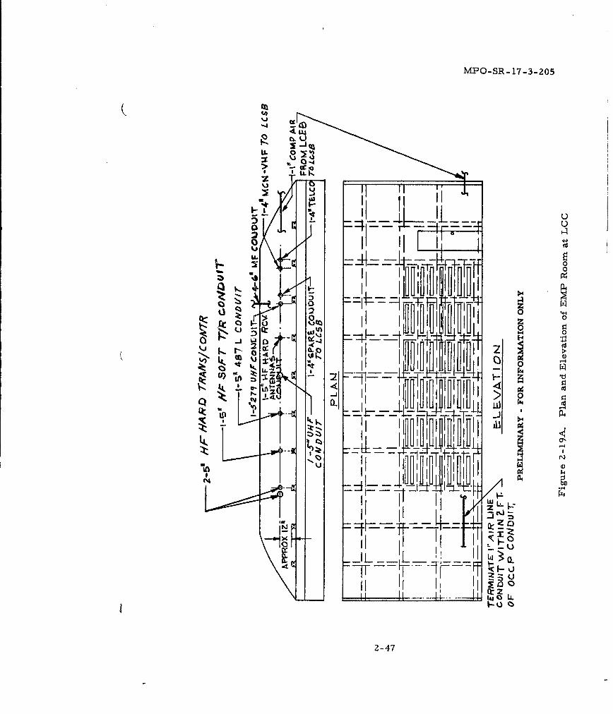
2-19A Plan and Elevation of EMP Room at LCC .......... 2-47
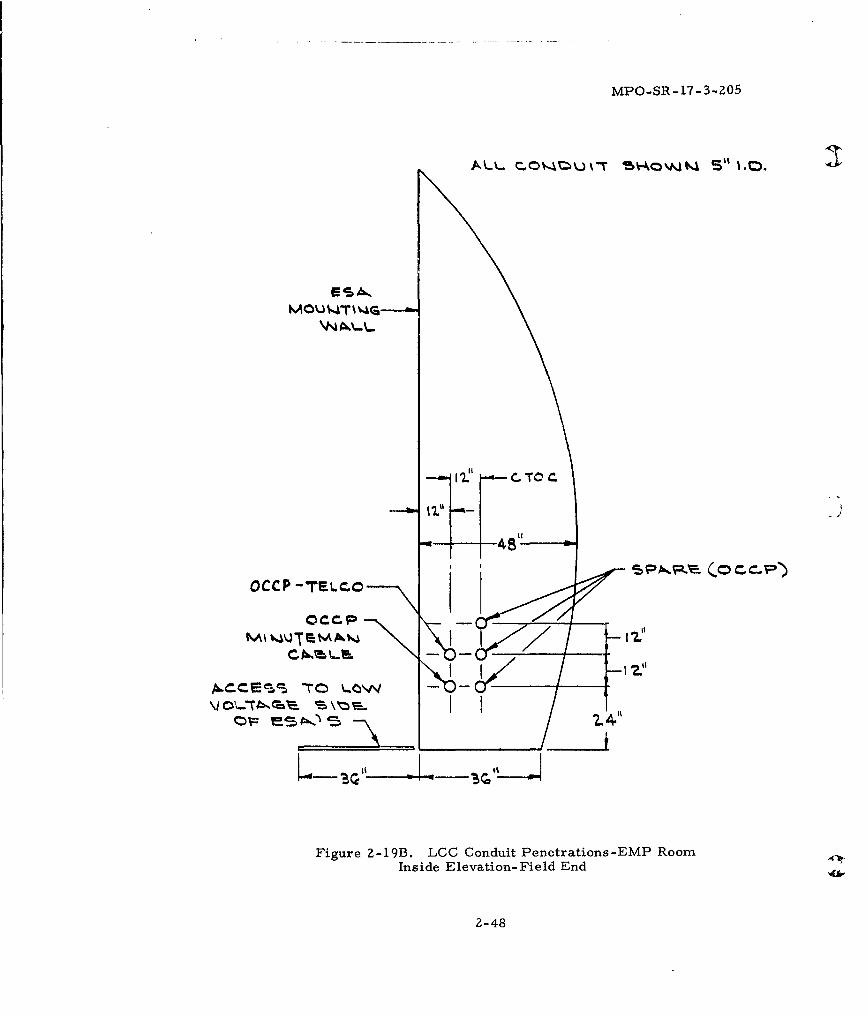
2-19B LCC Conduit Penetrations-EMP Room InsideElevation-Field End ............................... 2-48
2-20A ESA Interface at EMP Wall .......................... 2-49
2-20B View of Figure 2-20A with ESA Unit Removed ....... 2-50
2-20C View of Figure 2-20A with Site Structurein Phantom Rotated 90 . . . . . . . . . . . . . . . . . . . . . . . . . . . 2-51
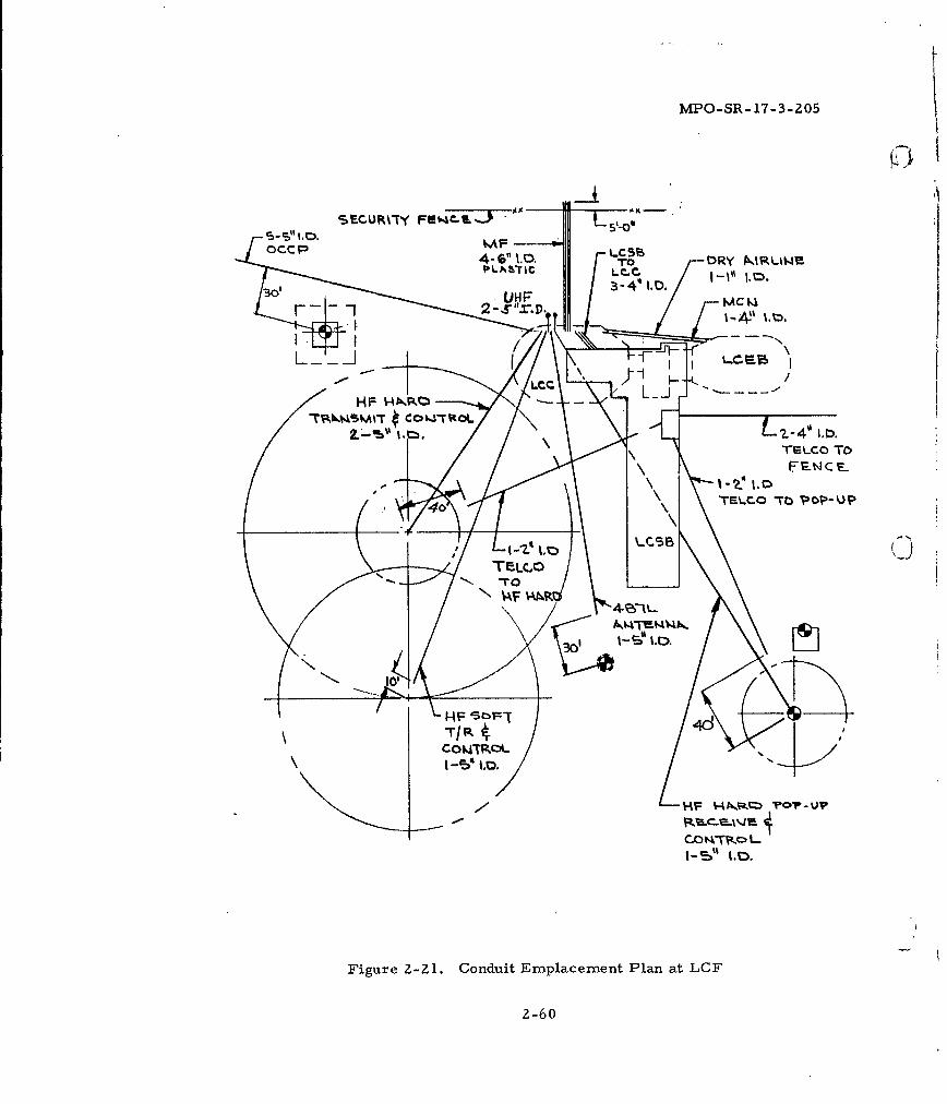
2-21 Conduit Emplacement Plan at LCF .................. 2-60
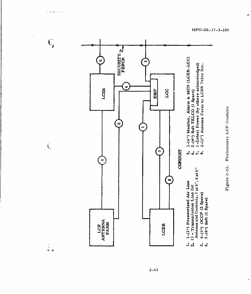
2-2 Preliminary LCF Conduits ......................... 2-61
viii
MPO-SR- 17-3-205
(. 'LIST OF ILLUSTRATIONS (Continued)
Figure Page
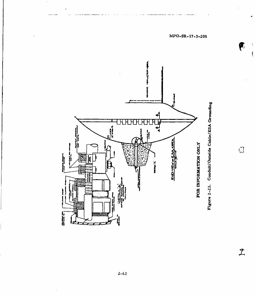
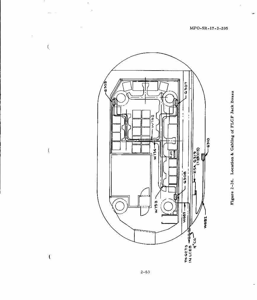
2-23 Conduit/Outside Cable/ESA Grounding ............. 2-6z2-24 Location & Cabling of FLCF Jack Boxes ............. 2-63
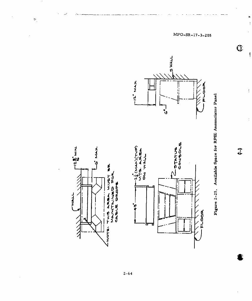
2-25 Available Space for RPIE Annunciator Panel ........ 2-64
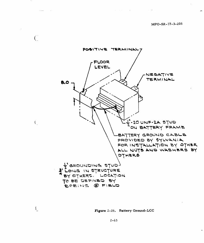
Z-Z6 Battery Ground-LCC ............................ Z-65
Z-27 Rack Grounding in LCC ........................... 2-66
2-28 Power Cable Routing to MG Set .................... 2-67
3-1 LCEB Equipment List ............................ \3-3
5-1 LCSB Equipment List ............................... 5-3
5-2 Equipment Layout MCN, LCSB ................... 5-7
5-3 LCSB Terminal Box ............................... 5-9
5-4 Bracket Dimensions of Hands-Free Telephone ...... 5-11
6-1 LF/LER First Level Floor Plan .................... 6-2
6-2 LF/LER Second Level Floor Plan ................. 6-3
6-3 LF Launcher Equipment Room Sectional View ...... 6-4
6-4 LF Antenna Tuner Set ........................... 6:-5
6-5 Radio Set (C&S) ................................... 6-6
6-6 Status Authentication System ...................... 6-7
6-7 Terminal, Digital Data ........................... 6-8
6-8 LER Equipment List ................................ 6-9
6-9 LF Conduits ...................................... 6-14
6-10 LF/LER First Level Jack Boxes ................... 6-18
6-11 LF/LER Second Level Jack Boxes ................. 6-19
6-1Z Mounting Detail LF Sump Pit Jack Box ............. 6-20
6-13 Conduit Penetration into LF/LER ................... 6-zl
6-14 LF Work Cage Jack Box ........................... 6-22
6-15 Rack Grounding in LF ............................ 6-23
6-16 Outline Dimensions of Alarm & Driver Assembly .... 6-24
7-1 LEB Equipment List ............................... 7-3
ix
MPO-SR-17-.3-205
LIST OF ILLUSTRATIONS (Continued)41
Figure Page
8-1 Antenna Farm Layout (LGF)........................ 8-5
8-2 LCF Antenna Farm Equipment List .................. 8-7
8-3 Antenna Form Layout (LF)......................... 8-9
8-4 LF Antenna Farm Equipment List ................... 8-11
9-1 Weatherproof Jack Box.............................9-2
9-2 Weatherproof Alarm Set ............................ 9-3
9-3 FLCF & LF Jack Box.............................. 9-4
9-4 Wall Mounted Telephone ............................ 9-5
LIST OF TABLES
Table Page
1-1 Abbreviations..................................... 1-2 AIN
1-2 Applicable Documents.............................. 1-3 q
x
C' MPO-SR-17-3-205
SECTION 1
INTRODUCTION
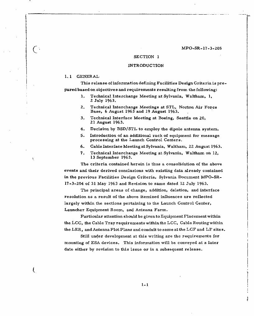
1. 1 GENERAL
This release of information defining Facilities Design Criteria is pre-
pared based on objectives and requirements resulting from the following:
1. Technical Interchange Meeting at Sylvania, Waltham, 1,2 July 1963.
2. Technical Interchange Meetings at STL, Norton Air ForceBase, 6 August 1963 and 19 August 1963.
3. Technical Interface Meeting at Boeing, Seattle on 20,21 August 1963.
4. Decision by BSD/STL to employ the dipole antenna system.
5. Introduction of an additional rack of equipment for messageprocessing at the Launch Control Centers.
6. Cable Interface Meeting at Sylvania, Waltham, Z2 August 1963.7. Technical Interchange Meeting at Sylvania, Waltham on 12,
13 September 1963.
The criteria contained herein is thus a consolidation of the above
events and their derived conclusions with existing data already contained
in the previous Facilities Design Criteria, Sylvania Document MPO-SR-
17-3-204 of 31 May 1963 and Revision to same dated 1Z July 1963.
The principal areas of change, addition, deletion, and interface
resolution as a result of the above itemized influences are reflected
largely within the sections pertaining to the Launch Control Center,
Launcher Equipment Room, and Antenna Farm.
Particular attention should be given to Equipment Placement within
the LCC, the Cable Tray requirements within the LCC, Cable Routing within
the LER, and Antenna Plot Plans and conduit to same at the LCF and LF sites.
Still under development at this writing are the requirements for
mounting of ESA devices. This information will be conveyed at a later
date either by revision to this issue or in a subsequent release.
1-1
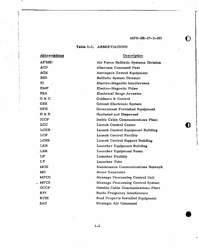
MPO-SR-17-3-205 0Table 1-1. ABBREVIATIONS
Abbreviations Description
AFBSD Air Force Ballistic Systems Division
ACP Alternate Command Post
AGE Aerospace Ground Equipment
BSD Ballistic System Division
EI Electro-Magnetic Interference
EMP Electro-Magnetic Pulse
ESA Electrical Surge Arrestor
G & C Guidance & Control
GES Ground Electronic System
GFE Government Furnished Equipment
H & D Hardened and Dispersed
ICCP Inside Cable Communications Plant
LCC Launch Control Center
LCEB Launch Control Equipment Building
LCF Launch Control Facility
LCSB Launch Control Support Building
LEB Launcher Equipment Building
.LER Launcher Equipment Room
LF Launcher Facility
LT Launcher Tube
MCN Maintenance Communications Network
MG Motor Generator
MPCU Message Processing Control Unit
MPCS Message Processing Control System
OCCP Outside Cable Communications Plant
RFI Radio Frequency InterferenceRPIE Real Property Installed Equipment
SAC Strategic Air Command
1-2
MPO-SR-17-3-205
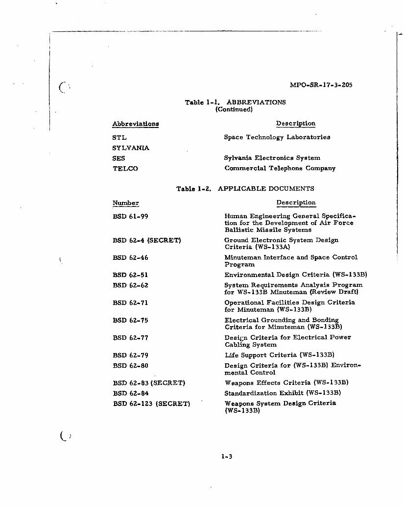
Table 1-1. ABBREVIATIONS(Continued)
Abbreviations Description
STL Space Technology Laboratories
SYLVANIA
SES Sylvania Electronics System
TELCO Commercial Telephone Company
Table 1-2. APPLICABLE DOCUMENTS
Number Description
BSD 61-99 Human Engineering General Specifica-tion for the Development of Air ForceBallistic Missile Systems
BSD 62-4 (SECRET) Ground Electronic System DesignCriteria (WS- 133A)
BSD 62-46 Minuteman Interface and Space ControlProgram
BSD 62-51 Environmental Design Criteria (WS-133B)
BSD 62-62 System Requirements Analysis Programfor WS-133B Minuteman (Review Draft)
BSD 62-71 Operational Facilities Design Criteriafor Minuteman (WS-133B)
BSD 62-75 Electrical Grounding and BondingCriteria for Minuteman (WS-133B)
BSD 62-77 Design Criteria for Electrical PowerCabling System
BSD 62-79 Life Support Criteria (WS-133B)
BSD 62-80 Design Criteria for (WS-133B) Environ-mental Control
BSD 62-83 (SECRET) Weapons Effects Criteria (WS-133B)
BSD 62-84 Standardization Exhibit (WS-133B)
BSD 62-123 (SECRET) Weapons System Design Criteria(WS-133B)
1-3
(. MPO-SR-17 -3-205
SECTION Z
LAUNCH CONTROL CENTER
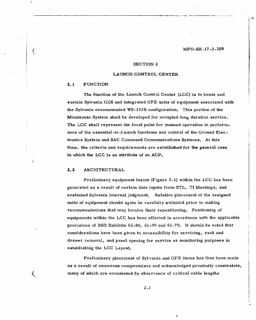
Z.1 FUNCTION
The function of the Launch Control Center (LCC) is to house and
sustain Sylvania GES and integrated GFE units of equipment associated with
the Sylvania recommended WS-133B configuration. This portion of the
Minuteman System shall be developed for occupied long duration service.
The LCC shall represent the focal point for manned operation in perform-
ance of the essential-to-1 aunch functions and control of the Ground Elec-
tronics System and SAC Command Communications Systems. At this
time, the criteria and requirements are established for the general case
in which the LCC is an attribute of an ACP.
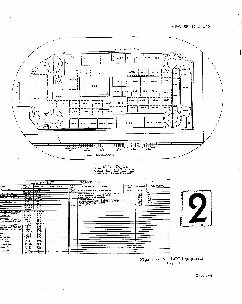
Z., Z ARCHITECTURAL
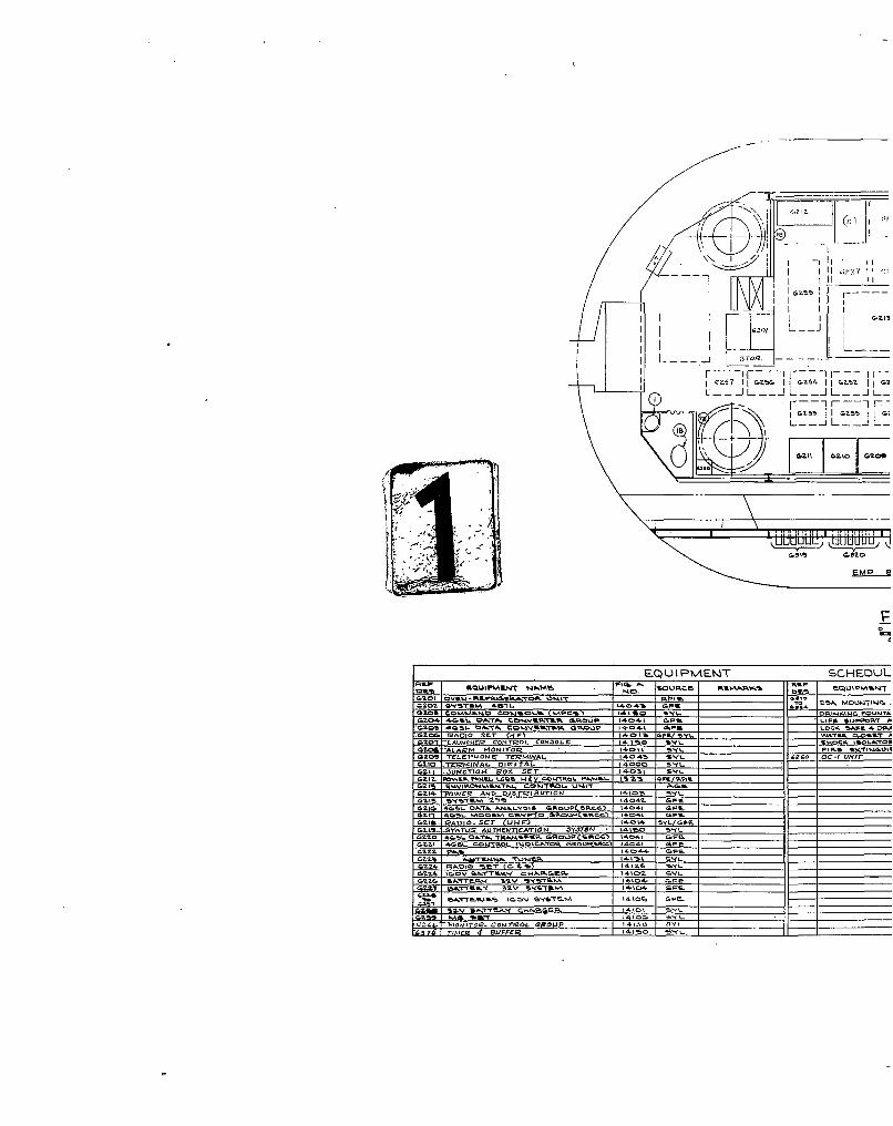
Preliminary equipment layout (Figure 2-1) within the LCC has been
generated as a result of certain data inputs from STL, TI Meetings, and
evaluated Sylvania internal judgment. Relative placement of the assigned
units of equipment should again be carefully qraluated prior to making
recommendations that may involve their repositioning. Positioning of
equipments within the LCC has been effected in accordance with the applicable
provisions of BSD Exhibits 6Z-80, 61-99 and 62-79. It should be noted that
considerations have been given to accessibility for servicing, rack and
drawer removal, and panel opening for service or monitoring purposes in
establishing the LCC Layout.
Preliminary placement of Sylvania and GFE items has thus been made
as a result of numerous compromises and acknowledged proximity constraints,
many of which are occasioned by observance of critical cable lengths
Z-1
MPO-SR-17-3-205
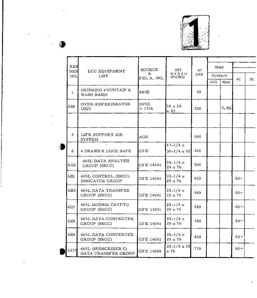
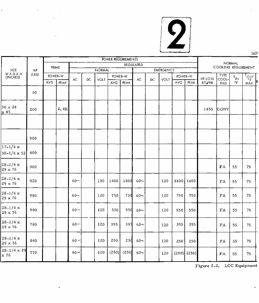
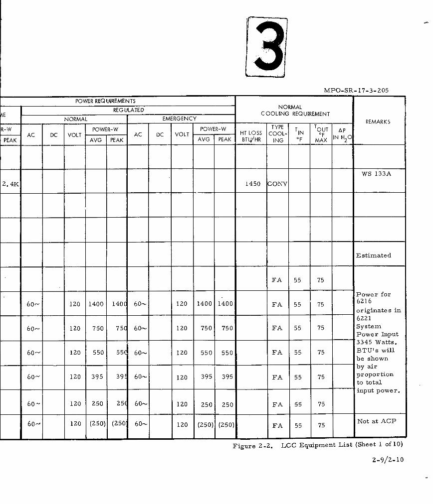
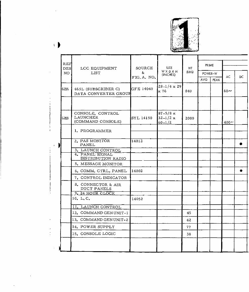
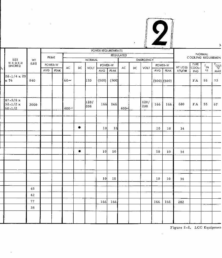
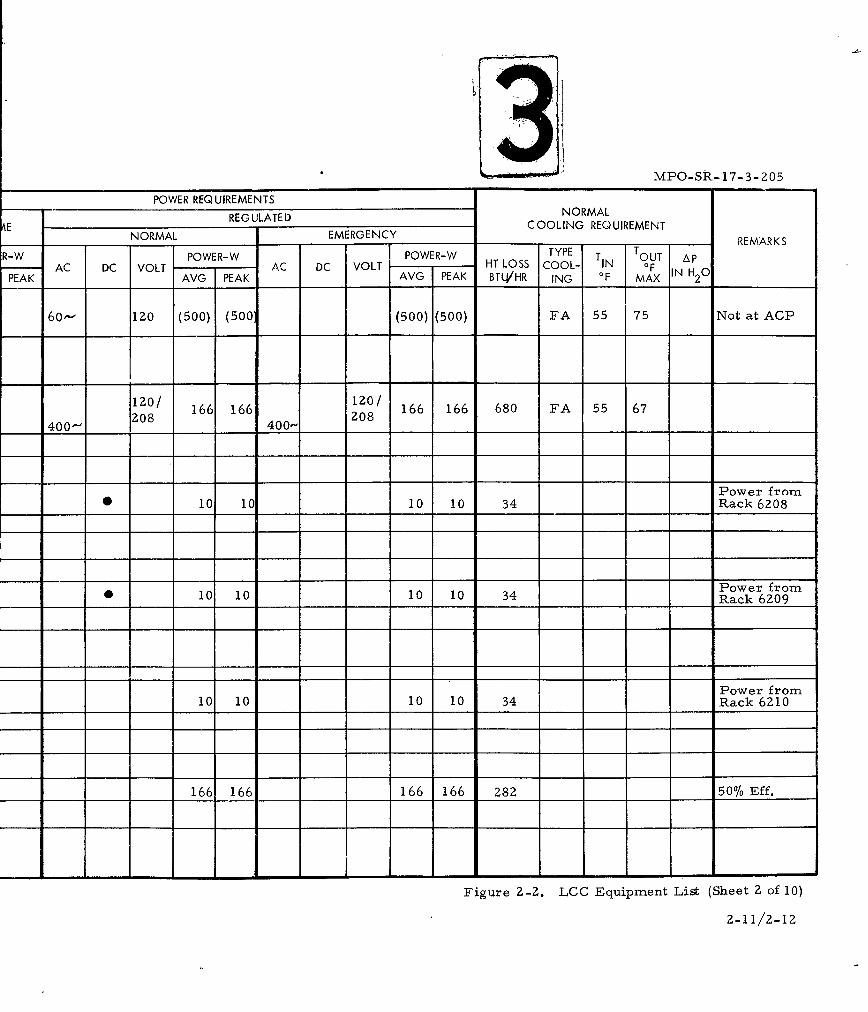
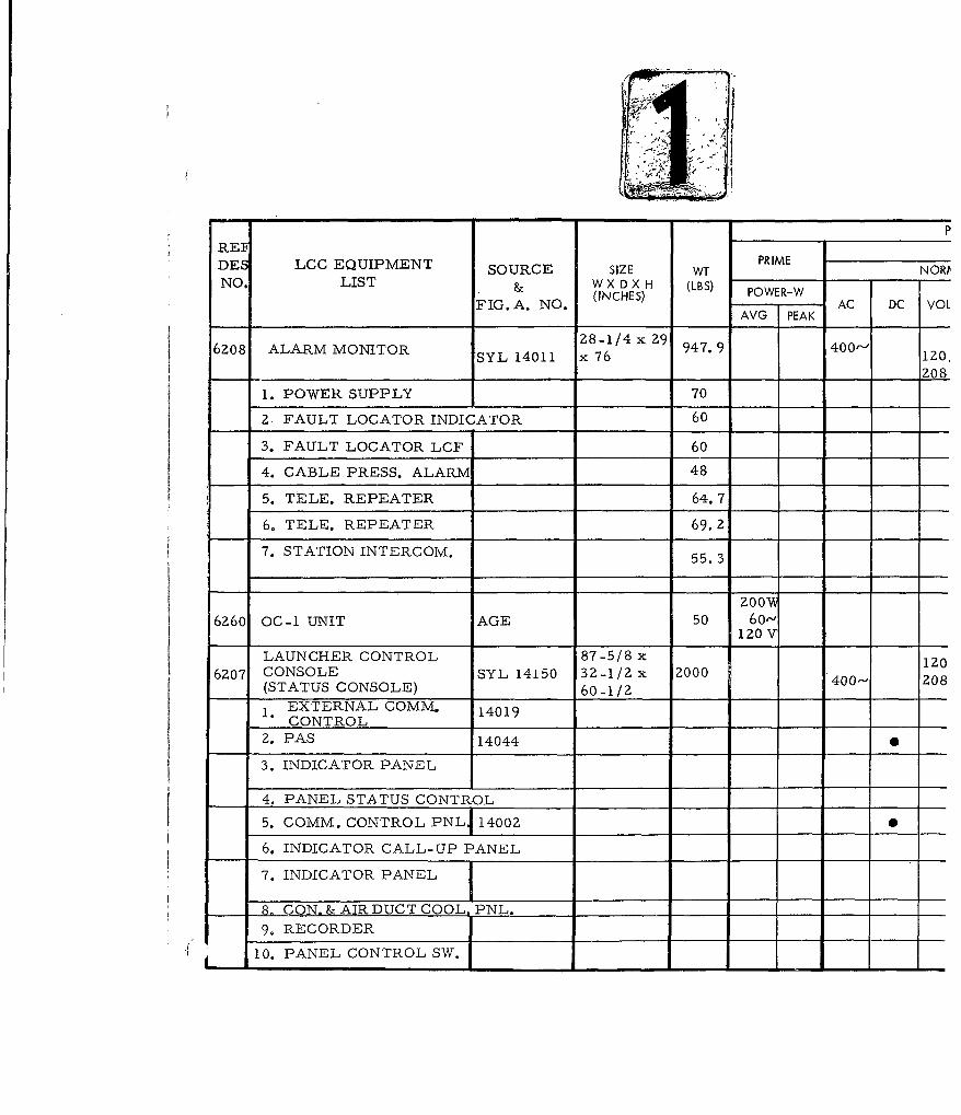
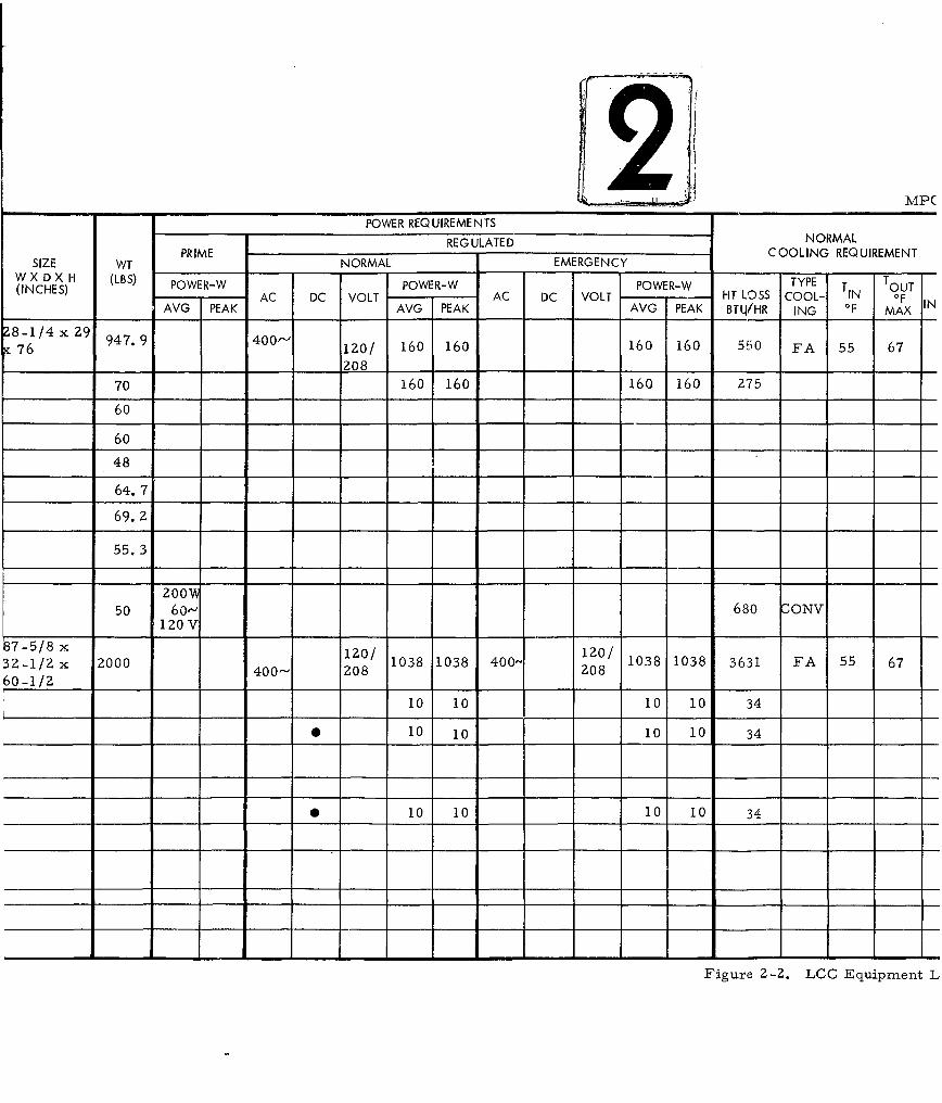
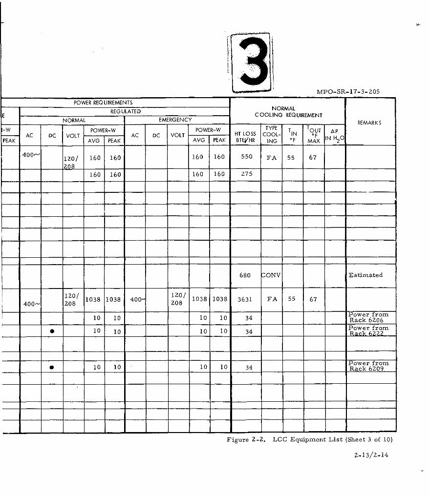
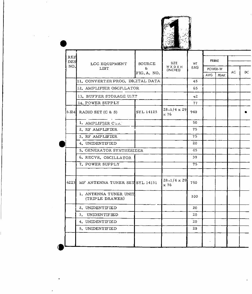
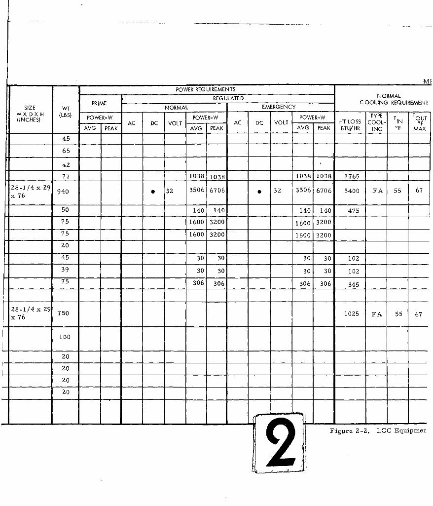
between racks and other units of equipment. Sizes of equipment to be
placed within the LCC are as shown on the Sylvania Equipment List,
Figure 2-2.
Physical constraints on maximum unit equipment size are imposed
for handling purposes. These figures are covered under Section 4,
Access Facility, of this criteria.
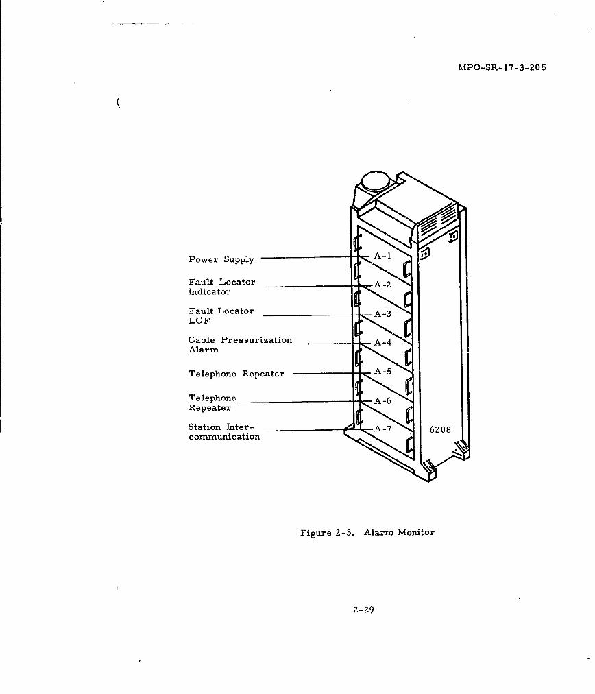
See Figures 2-3 through 2-18 for preliminary rack information.
The basis of design of the LCF evolves from the LCC equipment
layout. Major decisions relative to the Sylvania endorsed GES recom-
mendation for the LCF are founded on concepts of design basically com-
patible with the LCC configuration expressed herein.
Sufficient space shall be provided within the EMP Room (Figure
2-19) to allow a cable splicer and helper adequate room to perform their A
function. Conduit penetrations into this area shall not impede normal
access of personnel for installation or maintenance.
Additional storage volume within the LCC for personal equipment,
waste, custodial equipment, survival equipment storage, dry food storage
and water storage shall be provided by others in consonance with BSD
Exhibit 62-79. These are as follows:
Dry food storage 40 cu. ft
Water storage (includes 300 ga. potable) 2500 gal.
Waste containers 35 gal.
Custodial equipment 5 cu, ft.
Personal equipment 24 cu. ft
Clothing (survival period) 12 cu. ft.
Convenience storage 6 cu. ft.
Bedding 6 cu. ft.
Survival equipment 24 cu. ft.
2-2
'I,
I GZ57 Z64I _I I Q. IIGL I Lr I L - __j - -Lri]F ---I F7
F'_57F~ 1 1 GL ~ L~ J 1L . L_
52.1 1 GZ
_=Q11 52.10T SC tOP
.0!- SLK twanp7w MTM
G2* Ql MQp1 UI pKa E.N S.HEDUA
GZ .TrAN- alat R O NZO i4I t Q Yl, .C
0201 AL P :041__CsL ,spcqfl 141i SSo F-1 RraS %W0014Th52 ? 2T. 7 N A _ O M t6__ __. 4 4 0 _ _ _ __ _ _ _ _L~ U P R
52.10 -TE71MIAL 0101 TAt.i 4I0 S1( _______IZ SETC11 11 1403 .11 1______
GtIS- 6Y3T51AtI 14.4Z. OW _______
G2.15 - 2Z 0 O ETJSACM 14 101 SL50 _______ _____022,STTI.04UlAlJIC'TIO 0 YSTI j j________
0202. 04. 14044 20. ________ _______
GZZt iVrll45.02f.111 Glc __________ ________
-Z -&l.0I 10v S 'T.'LA 14105 a t
St S??P,(CIIA.0.50W 14101 3'IL ________
fl~f MSj~q 551 L405 . R____________
iff1 1. N1OZ.TC.CO~rQOL GROMP 1410 1/4) 14150 51(1. ____________
MP0- SR -17-3 -205
rvs Ij 7 --- J
i ; Z5 -- GZ5 LJ iL x 1 -'II L~ H n r- rI --- J
I ~~ ~ E -LiJ F- r - E 1 F I ~ iI II I
r 10
I C757 11 G0240 GII 4 CO--l L - §-J
4.Z~ ~g ~z. 01.3 .CO 4..01 200 *j~S 2
-zO0 F L~G24 I- - L --- 4 5 07 S *
_______ LQUI PKAEtT SC.HE.DULE_______
lWW1414 MRlE. 14e4 GPM M0114T144 %MSUbft
COIJZOLC IA1. sO SYI.. 514 w4IoLA rO SNS7ML' PIAAL, 11.
14011 691. FIIt UITI4OISEO 40
lAL 14045 syL 62co OCc, N'r AC
- [4000 SYL%
B-IrON 144.3 S91.
'IO -SYSEAI 1410.0 61.
'1410Z4 .4
00. M 411 1
14-0 S.01
0.0. ; It,1 ~ l
Figure 2- IA. LCG EquipmentLayout
2-3/2-4
MPO-SR-17-3-205
C,-4
R-94
2-5
MPO-SR -17-3-205
00
to "0
\t44
-o
C44
2-6
*2~~-4/ C-2M.
SECTIONI-A 5ECTION~ 'C-C'
J..-C' ar11 "Fa.. V
MPO-SR-17-3-205
-4- 1 C1
4 ,I I |"-"
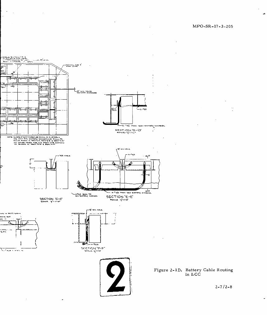
S Figure 2-1D. Battery Cable Routing
in LCC
2-7/2-8
2 EtIK '-
K
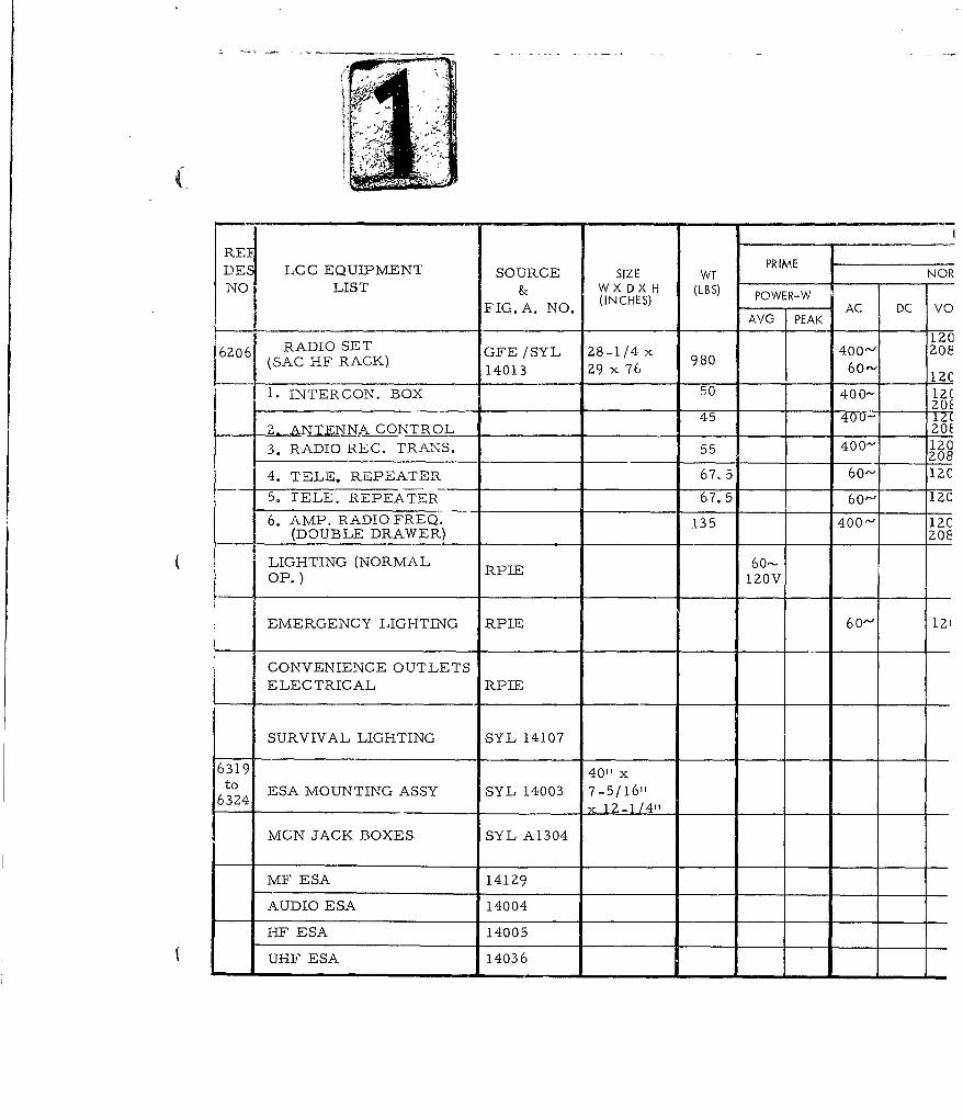
REI PR IMEDES LCC EQUIPMENT SOURCE SIZE WT
& WX DX H (LBS) OWwNO. LIST FIG. A. NO. (INCHES) AC DC
AVG PEAK
DRINKING FOUNTAIN &IRPIE 50WASH BASIN
6201 OVEN -REFRIGERATOR RPIE 30 x 24UNIT A 1336 x 4 zoo 2.4Kx 45__ __ _
5 LIFE SUPPORT AIR AGE 900SYSTEM
t.1 17-1/4 x
6 4 DRAWER LOCK SAFE GFE 30-1/4 x 52 400
465L DATA ANALYSIS Z8-1/4 x6Z16 GROUP (SRCC) GFE 14041 29 x 76 900
6221 465L CONTROL (SRCC) GFE 14041 Z8-1/4 x 9z7 66"INDICATOR GROUP Z9 x 76
62Z0 465L DATA TRANSFER 28-1/4 x 980 60-
GROUP (SRCC) GFE 14041 29 x 76
6Z17 465L MODEM CRYPTO 28-1/4 x 980 60-GROUP (SRCC) GFE 14041 29 x 76
6205 465L DATA CONVERTER Z8-1/4 x 780 60-GROUP (SRCC) GFE 14041 29 x 76
6204 465L DATA CONVERTER 28-1/4 x 840 60-
GROUP (SRCC) GFE 14041 Z9 x 76
465L (SUBSCRIBER C) 28-1/4 x 29 770 60-DATA TRANSFER GROUP GFE 14040 x 76
MPPOWER REQUIREMENTS
REGULATED NORMALPRIME COOLING REQUIREMENT
SIZE WT NORMAL EMERGENCYW X D X H (LBS) TYPE T(INCHES) POWER-W POWER-W POWER-W OUTAC DC VOLT AC DC VOLT HT LOSS COOL- IN OFAVG PEAK AVG PEAK AVG PEAK BTU/HR ING 0F MAX
50
30x24 200 2.4K 1450 CONVx 45
900
17-1/4 x
30-1/4 x 52 400
Z8-1/4 x FA 55 7529 x76
8-1/4x 920 60-' 120 1400 140C 60- 120 1400 1400 FA 55 75
29 x 76
Z8-1/4x 980 60- 120 750 75C 60'- 120 750 750 FA 55 7529 x 76
28-1/4x 980 60- 120 550 55C 60'- 120 550 550 FA 55 7529 x 76
Z8-1/4x 780 60- 120 395 39- 60- 120 395 395 FA 55 75
29 x 76
28-1/4x 840 60- 120 250 Z51 60-- 120 250 250 FA 55 7529 x 76
28-1/4 x 292 7 770 60- 1z0 (Z50) (250 60- 120 (250) (250) FA 55 7576
Figure 2-2. LCC Equipment
MPO-SR-17-3-205
POWER REQUIREMENTS
REGULATED NORMALE C OOLING REQUIREMENT
NORMAL EMERGENCY COOIN REQUIREMENT REMARKSR-W POWER-W POWER-W TYPE T TOUT Ap
AC DC VOLT AC DC VOLT HT LOSS COOL- IN OFPEAK AVG PEAK AVG PEAK BTU/HR ING OF MAX INH20
WS 133A
2. 4K 1450 CONV
Estimated
FA 55 75
Power for
60- 120 1400 140C 60- 120 1400 1400 FA 55 75 6Z16
originates in6221
60- iZ0 750 75C 60- 120 750 750 FA 55 75 SystemPower Input3345 Watts.
60- 120 550 55 60- 120 550 550 FA 55 75 BTU's willbe shown
by air
60- 120 395 39 60- 120 395 395 FA 55 75 proportionto total
I input power.
60- 120 Z50 25] 60- 120 250 250 FA 55 75
60- 1Z0 (250) (250 60- 120 (250) (250) FA 55 75 Not at ACP
I I - - - - -III - I - - - -
Figure 2-2. LCC Equipment List (Sheet 1 of 10)
2-9/z-10
REF PR IMEDES LCC EQUIPMENT SOURCE SIZE WT
NO LIST & W X D X H (LBS) POWER-W(INCHES)AC CFIG. A. NO. AVGAC DC
AVG PEAK
6Z76 465L (SUBSCRIBER C) GFE 14040 281/4 x 29
DATA CONVERTER GROU x7 6 840 60'
- CONSOLE, CONTROL 87-5/8 x
6203 LAUNCHER SYL 14150 32-1/Z x 2000(COMMAND CONSOLE) 60-1/2 400-
1. PROGRAMMER
2. PAS MONITOR 1401ZPANEL S
3. LAUNCH CONTROL4. PANEL SIGNAL
DISTRIBUTION RADIO
5. MESSAGE MONITOR
6. COMM. CTRL. PANEL 14002 Z
7. CONTROL INDICATOR
8. CONNECTOR & AIRDUCT PANELS
29, 4 HOUR CLOCK
10. L.C. 14052
11. LAUNCH CONTROL
12, COMMAND GEN UNIT- 1 45
13. COMMAND GENUNIT-2 42
14, POWER SUPPLY 77
15. CONSOLE LOGIC 38
POWER REQUIREMENTS
REGULATED NORMALSIZE WT PIENORMAL EMERGENCY COIGRQIEE
W X D X H (LBS)T(INCHES) POWER-W POWER-W POWER-W TYPE T ouiAC DC VOLT AC DC VOLT HT LOSS COOL- IN OF
AVG PEAK AVG PEAK AVG PEAK BTU/HR ING OF MAX
Z8-1/4 x 29x 76 840 60'- 120 (500) (500 (500) (500) FA 55 75
87-5/8 x12/l/32-1/2x 2000 2Z08 166 166 20/ 166 166 680 FA 55 6760 -1/Z 400-. 400-2
*10 10 10 10 34
*10 10 10 10 34
10 10 10 10 34
45
42
77 _________166 166 166 166 282 __
38
Figure 2-2. LOG Equipmen
MPO-SR-17-3- 205
POWER REQ UIREMENTSj RE GULATE D N ORMALREGUATEDCOOLING REQUIREMENT
E NORMAL EMERGENCY COOLING REURMN REMARKS
R-W POWER-W POWER-W TYPE T OUT Ap
AC DC VOLT AC DC VOLT POE- HT LOSS COOL- IN OF IN H 0PEAK V G PEAK AVG PEAK BTU/HR ING OF MAX 20
60,- 120 (500) 1 (500- (500) (500) FA 55 75 Not at ACP
Z/ 166 166 10/ 166 166 680 FA 55 67
400' " 208 400 208
10 10 10 10 34 Rack 6208
Power from*10 10 10 10 34Rack 6209
Power from10 10 10 10 34 Rack 6210
166 166 1__ 166 166 Z82 ______50% Eff.
Figure 2-2. LCC Equipment List (Sheet ? of 10)
2-i11/2-12
!p
P
REFDES LCC EQUIPMENT PRIME
SOURCE SIZE WT NORPNO. LIST & w x D X H (LBS)
FIG. A. NO. (INCHES) POWER-W AC DC VOLAVG PEAK
6208 ALARM MONITOR SYL 14011 x76 947.9 400-zo~Z08
1. POWER SUPPLY 70
2- FAULT LOCATOR INDICATOR 60
3. FAULT LOCATOR LCF 60
4. CABLE PRESS. ALARM 48
5. TELE. REPEATER 64.7
6. TELE. REPEATER 69.2
7. STATION INTERCOM. 55.3
200'W
6Z60 OC-I UNIT AGE 50 60-120 V
LAUNCHER CONTROL 87-5/8 x IZ0
6207 CONSOLE SYL 14150 3Z-1/Z x 2000(STATUS CONSOLE) 60-1/Z2
1. EXTERNAL COMM. 14019CONTROL
2. PAS 14044 0
3. INDICATOR PANEL
4. PANEL STATUS CONTROL
5. COMM. CONTROL PNL 14002 0
6. INDICATOR CALL-UP PANEL
7. INDICATOR PANEL _
8. CON. & AIR DUCT COOL PNL.
9. RECORDER
[10. PANEL CONTROL SW.
.... , ' !MPC
POWER REQUIREMENTS
REGULATED NORMAL
SIZE WT PRIENORMAL EMERGENCY C L RUMW X D X H (LBS) TYPE -
(INCHES) POWER-W OWER-W POWER-W TOUTAC DC VOLT AC DC VOLT HT LOSS COOL- IN OF INAVG PEAK PEAK AVG PEAK BTI./HR ING F MAX
2.8 - 1/ 4 x 29 9 4 .90 076 9 i/ 160 160 160 160 550 FA 55 67
708
70 160 160 160 160 275
60
60
48
64. 7
69. 2
55.3
zooh50 6o-" 680 :ONV
120 V
7-5/8 x v120/ 120/ 1-/x 00400'-" 208 208
2-1/2 x 2000 40- 28 1038 1038 400- 20/ 1038 1038 3631 FA 55 6760-1/210 10 10 10 34
10 10 10 10 34
10 10 10 10 34 __
Figure 2-2. LCC Equipment L
V
MPO-SR-17-3-205
POWER REQ UIREMENTS
REGULATED NORMALNORMAL EMERGENCY ____RKSCOOLING REQUIREMENT
-W POWER-W POWER-W TYPE TOUT APAC DC VOLT AC DC VOLT HT LOSS COOL- IN OF
PEAK AVG PEAK AVG PEAK BTU/HR ING OF MAX IN H20
400- I.0/ 160 160 160 160 550 FA 55 67
208160 160 160 160 275
680 CONV Estimated
120/ 1038 1038 400-1 120/ 1038 1038 3631 FA 55 67
400- 208 208
Power from10 10 10 10 34 Powe fromRack 6206
Power from10 10 10 10 34 lac_6222
S10 1Power from• 10 10 10 10 34 _Rack 6209
Figure 2-2. LCC Equipment List (Sheet 3 of 10)
2-13/2-14
REFDES LCC EQUIPMENT SOURCE SIZE WT PRIME
NO. LIST & W X D X H (LBS) POWER-W(INCHES)PO E-
FIG. A. NO. AVG PEAK AC DC
11. CONVERTERPROG. DICITAL DATA 45
12. AMPLIFIER OSCILLATOR 65
13. BUFFER STORAGE UITET 12
14. POWER SUPPLY 77
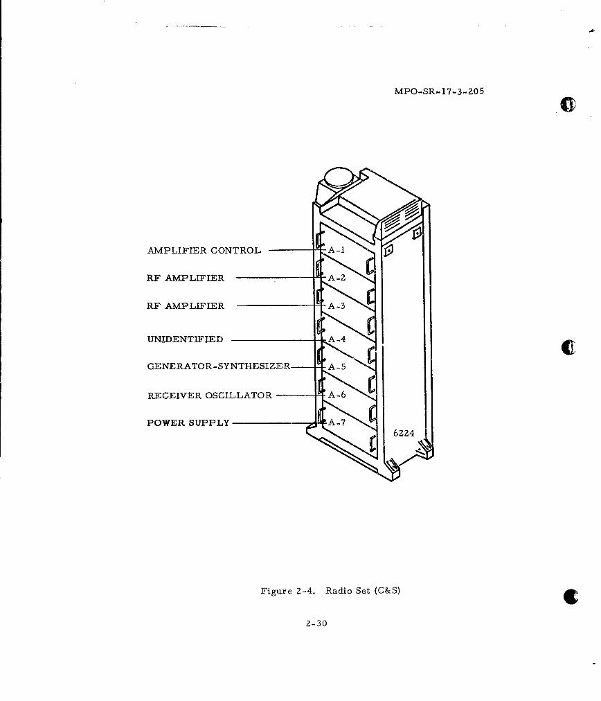
62Z4 RADIO SET(C & S) SYL 141Z5 28-1/4x2940x76
1. AMPLIFIER C-±C 50
2. RF AMPLIFIER 75
3. RF AMPLIFIER 75
4. UNIDENTIFIED 20
5. GENERATOR SYNTHESIZER 45
6. RECVR. OSCILLATOR 39
7. POWER SUPPLY 75
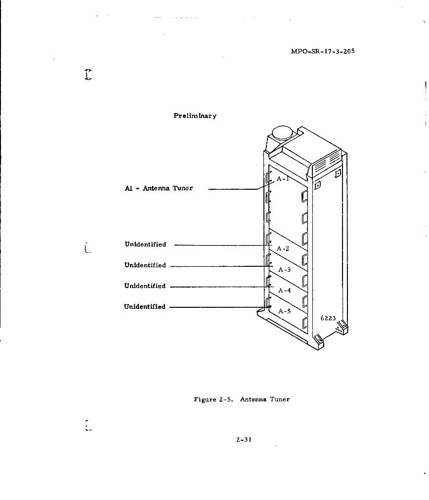
6Z23 MF ANTENNA TUNER SET SYL 14131 Z8-1/4 Z9 750x76 7
1. ANTENNA TUNER UNIT 100(TRIPLE DRAWER)
Z. UNIDENTIFIED z0
3. UNIDENTIFIED Z0
4. UNIDENTIFIED 20
5. UNIDENTIFIED z0
MlPOWER REQ UIREMENTS
REGULATED NORMALPRIME C OOLING REQUIREMENT
SIZE WT PRIME NORMAL EMERGENCY
(INCHES) POWER-W POWER-W POWER-W TYPE T OUTAC DC VOLT AC DC VOLT HT LOSS COOL- IN F
AVG PEAK AVG I PEAK AVG PEAK BTL/HR ING °F MAX
45
65
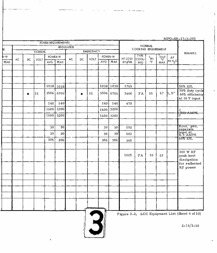
77 .__1038 1038 " 1038 1038 1765._
Z8-1/4x 29 940 * 32 3506 6706 32 3506 6706 5400 FA 55 67x 76
50 140 140 140 140 475
75 1600 3200 1600 3200
75 1600 3200 1600 3200
zo
45 30 30 30 30 102
39 30 30 30 30 102
75 306 306 306 306 345
28-1/4x 29 750 1025 FA 55 67
x 76
100
20
20
20
zo
20 Z L
_ _ _ _ _ .3--, -,
_____________________________________________MPO-SR-17-3-205-
POWER REQUIREMENTSREGUATEDNORMAL
REGULATE EM R E C COOLING REQUIREMENT
NORMA EMERAENCZ-W POWER-W POWER-W TYPE T .- REAKT OUT Ap
AC DC VOLT AC DC VOLT HT LOSS COOL- IN OF IN H 01PEAK AVG PEAK AVG PEAK BTU/HR ING OF MAX 2
____ ____1038 1038 ______ ___1038 1 038 1765 __ 5076 Eff.
3506670 * 2 306 706 540 FA 55 7 1 5" 50%6 duty cycE32 301603Z 30 676 50 FA 5 6715" 607o efficienc
____ ________at 36 V input
140 140 140 140 475
1600 3200 1600 3200
1600 3200 1600 3200
30 30 30 30 102 RcEvr. pwr.____ ____ ____ ____ ________ ____ selparate
30 30 30 30 102 inpAutat
306 306 306 306 345 6%Ef
300 W RF1025 FA 55 67 peak heat
____ ____ ____ ___ _ ____ ___ ____ ______ _______ _ _ ___ dis sipation
for reflectedRF power
Figure 2-2. LCC Equipment List (Sheet 4 of 10)
2-15/2-16
RE _____REF PRIM EDES LCC EQUIPMENT SOURCE SIZE WT NNO. LIST & W X D X H (LBS) POWER-W
FIG. A. NO. (INCHES)AVG PEAK AC DC
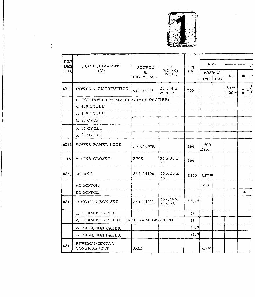
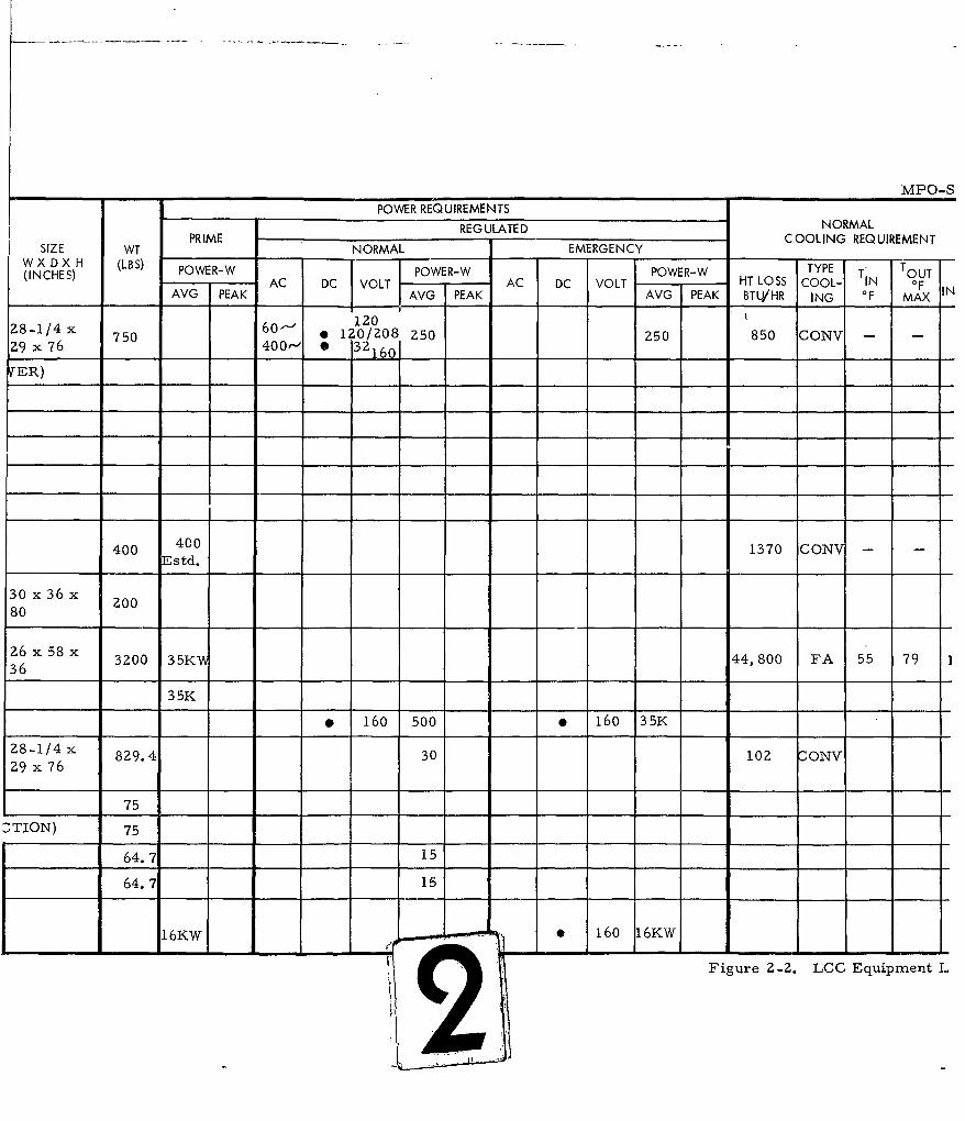
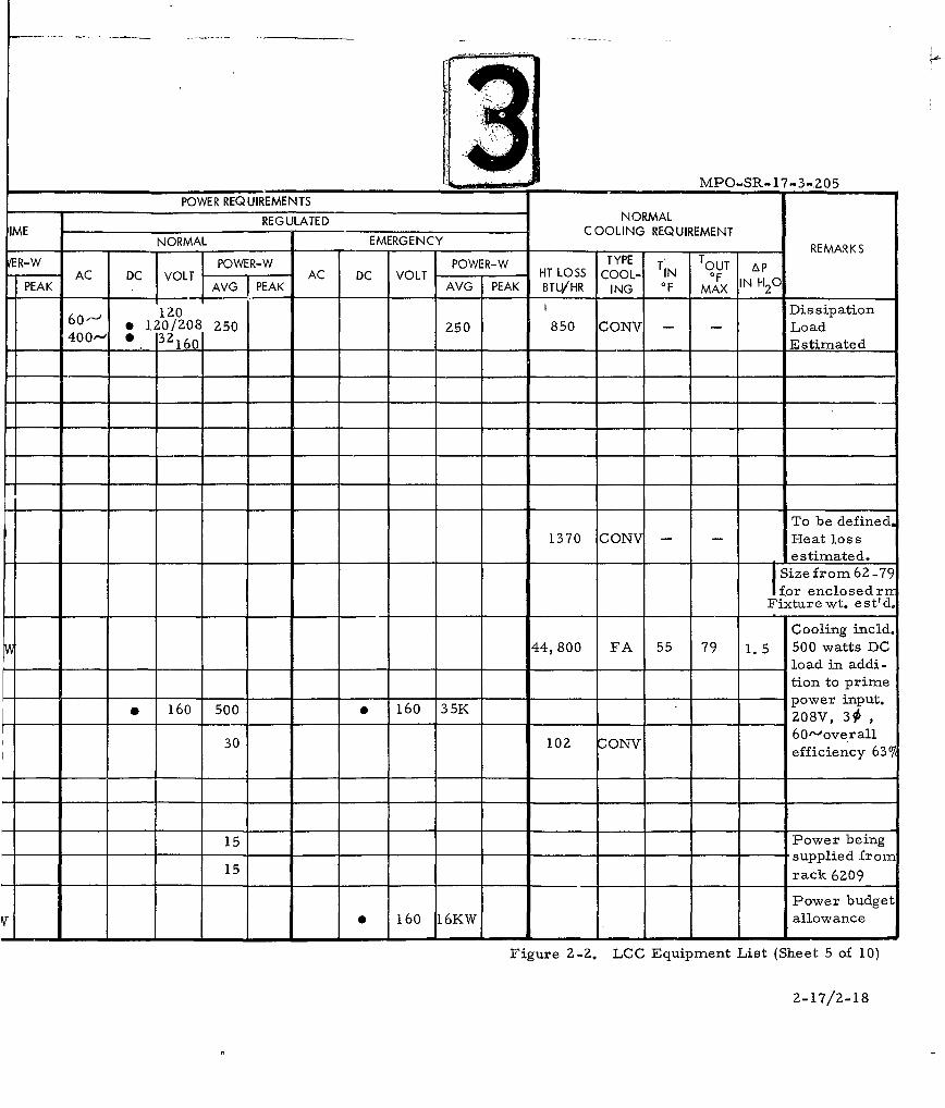
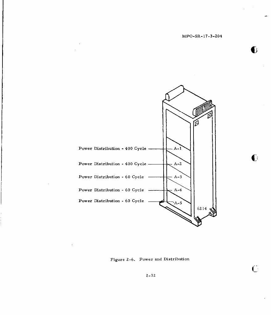
6214 POWER & DISTRIBUTION SYL 14103 26x0 750 400, S3
1. FOR POWER BRKOUT (DOUBLE DRAWER) __ _
2. 400 CYCLE
3. 400 CYCLE _ __
4. 60 CYCLE
5. 60 CYCLE
6. 60 C fCLE
6212 POWER PANEL LCDB GFE/RPIE 400 400Estd.
18 WATER CLOSET RPIE 30 x 36 x 2080
6259 MG SET SYL 14106 26 x 58 x 3200 35K36
AC MOTOR 35K
DC MOTOR S
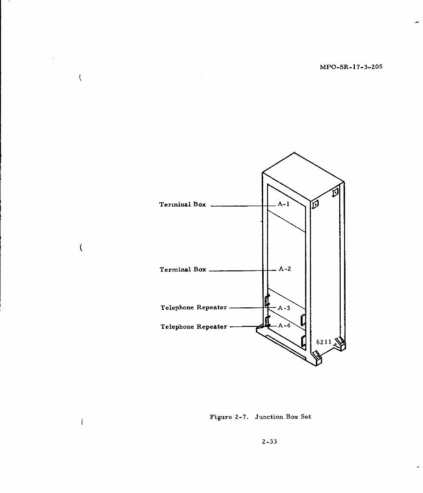
6211 JUNCTION BOX SET SYL 14031 28-1/4x 8Z9.429 x 76
1. TERMINAL BOX 75
2. TERMINAL BOX (FOUR DRAWER SECTION) 75
3. TELE. REPEATER 64.7
4. TELE. REPEATER 64.-7
6213 ENVIRONMENTALCONTROL UNIT AGE 16KW
MPO-SPOWER REQUIREMENTS
REG ULATE D NORMALPRIME ,C OOLING REQUIREMENTSIZE WT NORMAL EMERGENCY
W X D X H (LBS) TP(INCHES) POWER-W POWER-W POWER-W TYPE T' TOUTIC)AC DC VOLT AC DC VOLT HT LOSS COOL- IN OFAVG PEAK AVG PEAK AVG PEAK BTI4/HR ING OF MAX
12028-i/4x 750 60"'* 1. 0/208 250 250 850 CONVZ9 x 76 400' * 3216VER) 1
400 400 1370 CON -
Estd.
30 x 36x 20080
26 x 58 x 32 0 35 W63200 35K 44,800 FA 55 7936
35K
2 160 500 * 160 35K
29 x/7x 829.4 30 102 CONV29 x 76
75
6TION) 75
64.7 1564.7 15
16KW . 160 16KW
Figure 2-2. LCG Equipment L
__________________________________________________MPO-SR- 17-3 -.205
POWER REQUIREMENTS
REGULATED NORMALIME NOMLEMREC COOLING REQUIREMENTREAK
ER-W POWER-W POWER- TYPE T TOU AAC DC VOLT AC DC VOLT HTLS COOL- O F IN H 01
PEAK AVG PEAK AVG KPEAK IBTU/HR ING OF MAX 2
60120 Dis sipation0 120o/208 250 250 850 CONV - -Load
400- 10 2160 _____ __ ___Estimated
To be defined.1370 CON - Heat loss
____ ____ ____ ____ ____ ____ ___e stimnated.4Size from 62-79for enclosedrrr
Fixturewt. est'd.
Cooling incld.44, 800 FA 55 79 1. 5 500 watts DC
_______ ___ __ _ _ __ _ __ ___ load in addi-
tion to prime* 16 500* 16 35Kpower input.
-6 500_ 160_ 35K ___08V, 30#
30 10 V6 0'-overall102 ONVefficiency 63T
15 Power being-supplied from
15 rack 6209
Power budgetv0 160 16KW allowance
Figure Z-2. LCC Equipment List (Sheet 5 of 10)
2-17/2-18
REFP MDES LOG EQUIPMENT SOURCE SIZE WT ____
NO LIST &W X D X H (IBS) POWER-W
FIG. A. NO. (NHS AVG PEAK AC DC
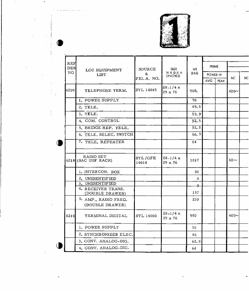
6209 TELEPHONE TERM. SYL 14045 28-1/4 x 960. 400-~29 x 76
1. POWER SUPPLY 70
2. TELE, 49.5
3. TELE. 53.9
4. COM. CONTROL 5Z. 5
-5. BRIDGE REP. TELE. 52.5
6. TELE. SELEC. SWITCH 66. 7-
7. TELE. REPEATER 64
6Z8 RADIO SET SYL/GFE 28-1/4x 11
6Z8(SAC UHF RACK) 14014 29 x 76 6017-6o
1. INTER*CON. BOX 50
2. UNIDENTIFIED r____ 5 __ _
3. UNIDENTIFIED_______
4. RECEIVER TRANS.___ (DOUBLE DRAWER) ____________157
5- AMP., RADIO FREQ. Z3 0
(DOUBLE DRAWER)
6210 TERMINAL DIGITAL SYL 14000 2814x 950 400-29 x 76
1. POWER SUPPLY 70
2. SYNCHRONIZER ELEC. 46
3. CONy. ANALOG-DIG. 62. 5-
4. CONV. ANALOG-DIG. 64
POWER REQ UIREME N TS
REG ULATE D NORIPRIME RGUAEDC OOLING
SOURCE SIZE WT PRIME NORMAL EMERGENCY ______ G
& W X D X H (LBS) TYPED(INCHES) POWER-W POWER-W POWER-W
IG.A.AC DC VOLT AC DC VOLT HT LOSS COOL-, AVG PEAK AVG PEAK AVG PEAK BTU/HR ING
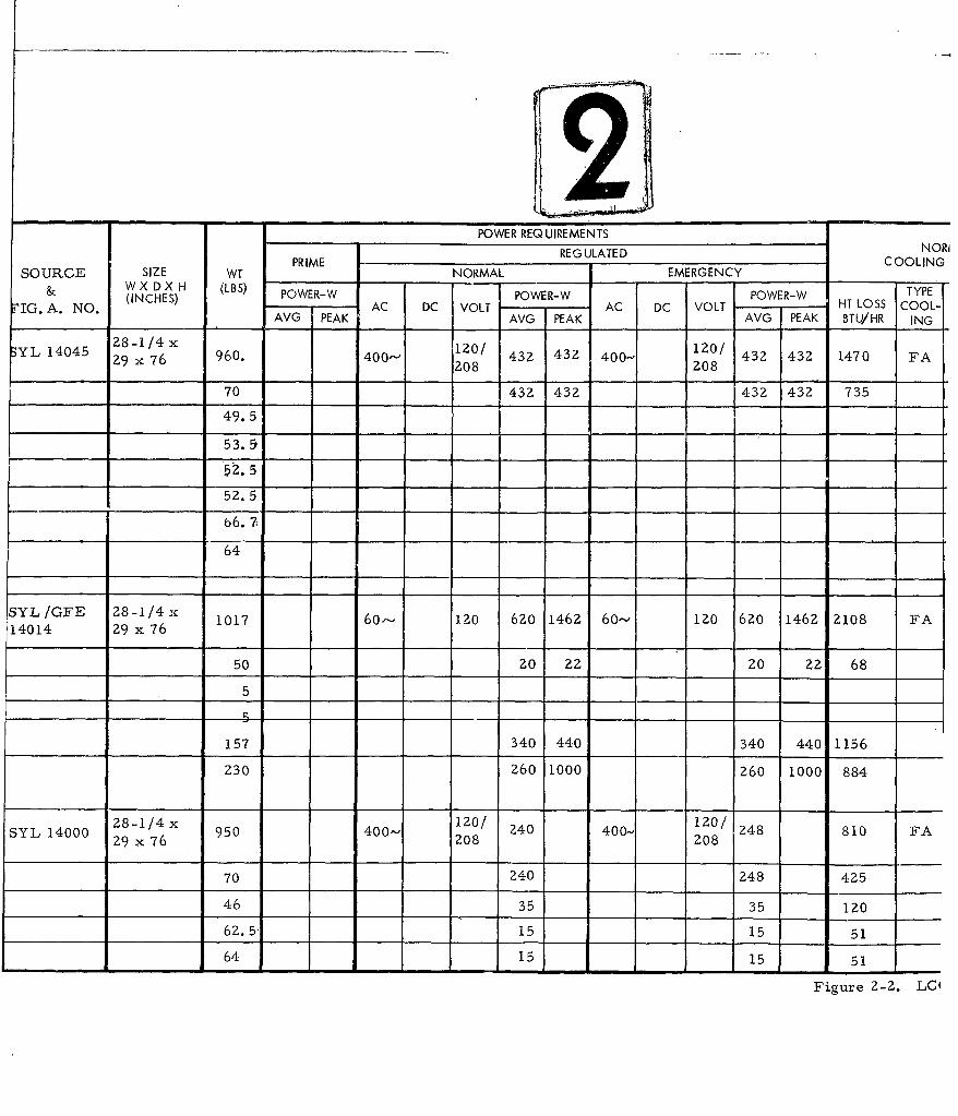
YL14045 Z-1/4x 1zo/ 120/ 432 1470 PA
29 x 76 960. 400208 432 432 4002 FA
70 432 432 432 432 735
49.5
53.9
52.5
52. 5
66. 7:
64
SYL/GFE 28-1/4x 1017 60-- 120 6Z0 146Z 60-- 120 620 146Z 2108 FA14014 29 x 76
50 z0 2z 20 22 68
5
157 340 440 340 440 1156
Z30 260 1000 260 1000 884
28-1/4 x 400- 120/ 240 400 120/ 248 810 FASY 100 29 x 76 95 0 208 Z08
70 240 248 425
46 35 35 1z0
62.5- 15 15 51
64 15 15 51
Figure Z-2. LCI
MPO-SR- 17-3-205
POWER REQUIREMENTS -
REGULATED NORMALE COOLING REQUIREMENT
NORMAL EMERGENCY, REMARKS
R-W POWER-W POWER-W TYPE T OUT ApI AC DC VOLT AC DC VOLT HT LOSS COOL- IN OF IN H 0
PEAK AVG PEAK AVG PEAK BTU/HR ING OF MAX 2
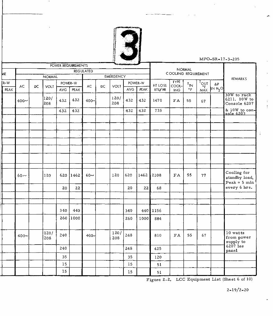
30W to rack40-Z0/ 120/ 432 432 1470 FA 55 67 6211. 1OW to
Z400- 208 208 Console 6207
432 432 432 432 735 & l0W to con-sole 6203
6o- 120 620 146Z 60- 120 620 1462 2108 FA 55 77 Cooling for
standby load.
- .Peak = 5 ain,20 2Z 20 22 68 every 6hrs.
340 440 340 440 1156
Z60 1000 260 1000 884
120/ 240 400- 120/ 248 810 FA 55 67 10 watts400 2 08 208 from power
supply to
240 248 425 6207 les
____ ____ __ __ _ ____ ____ ____ panel
35 35 I0
15 15 51
15 15 51
Figure 2-2. LCC Equipment List (Sheet 6 of 10)
2-19/2-20
>, o'
PREPMDES LCC EQUIPMENT SOURCE SIZE WT PRIMER
NO. LIST & W X D X H (LBS) POWER-WFIG. A. NO. (INCHES) AC DC VOL
AVG PEAK
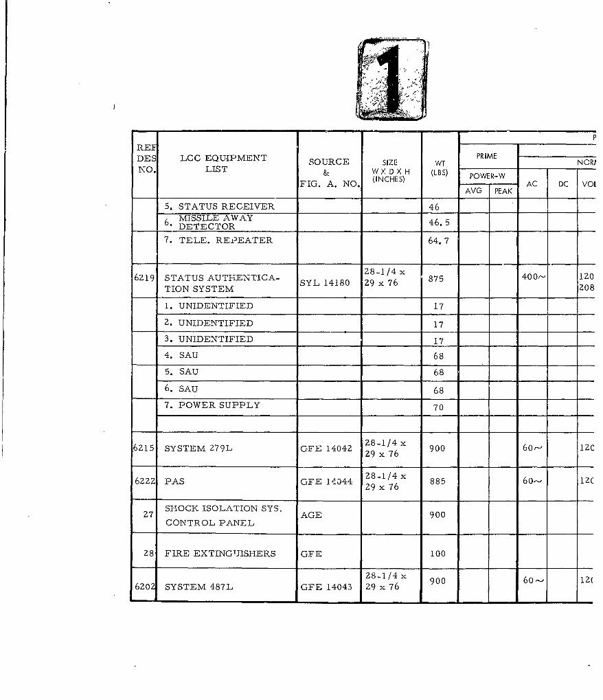
5. STATUS RECEIVER 466. MISSILE AWAY6. DETECTOR 46.5
7. TELE. REPEATER 64.7
6Z19 STATUS AUTHENTICA- Z8-1/4 x 875 400- IZ0TION SYSTEMSYL 14180 Z9 x 76 20TION SYSTEM Z0 8
1. UNIDENTIFIED 17
2. UNIDENTIFIED 17
3. UNIDENTIFIED 17
4. SAU 68
5. SAU 68
6. SAU 68
7. POWER SUPPLY 70
.6Z15 SYSTEM 279L GFE 14042 Z8-1/4 x 900 60- IZC29 x 76
6ZZ2 PAS GFE 14044 Z8-1/4x 885 60- 12C29 x 76
27 SHOCK ISOLATION SYS. AGE 900CONTROL PANEL
Z8 FIRE EXTINGTJISHERS GFE 100
28-1/4 x620 SYSTEM 487L GFE 14043 29 x 76
MPO-SR- I
POWER REQUIREMENTS
REG ULATED NORMALiPRIME C OIGREQ UIREMENT
SIZE WT PRIME NORMAL EMERGENCY COIGRQREN
X D X H (LBS) POWER-W POWER-W POWER-W TYPE T TOUTCHES) AC DC VOLT AC DC VOLT HT LOSS COOL- IN OF Ap
AVG PEAK AVG PEAK AVG PEAK BTU/HR ING OF MAX !N H2C
46 15 15 51
46.5 20 20 68
64.7 10 10 34
1/4xI0 181 76 875 400- 1z0/ 158 400- 540 FA 55 67Z08 Z08
17
17
17
68
68
68
70 158 240 158 240 270
1/4x 900 60-' 120 100 100 60- 120 100 100 340 FA 55x 76
1/4 x 885 60- 120 Z30 230 60- 1Z0 Z30 Z30 780 FA 55
x 76
900
100
-1/4 x 900 60--' 120 500 500 60'- 1Z0 500 500 1725 FA 55
x 76
Figure Z-Z. LOC Equipment List
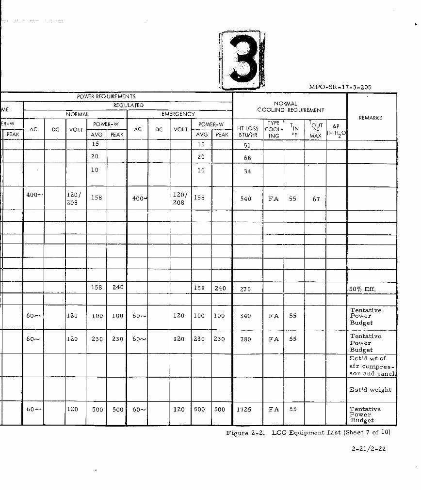
MPO-SR- 17-3-205
POWER REQUIREMENTSREG ULATE D NORMAL
ME N COOLING REQUIREMENTNORMAL EMERGE NCY ___REMARKS
ER-W POWER-W POWER-W TYPE T TUT ApAC DC VOLT AC DC VOLT HT LOSS COOL- IN OF
PEAK AVG PEAK AVG PEAK BTU/HR ING 0F MAX IN H20
15 15 51
20 20 68
10 10 34
400- IZ0/ 158 400- 120/ 158 540 FA 55 67208 208
158 240 158 240 270 50% Eff.
Tentative60, 120 100 100 60-- 120 100 100 340 FA 55 Power
Budget
60--- 120 230 230 60-' 120 .230 230 780 FA 55 TentativePower
Budget
Est'd wt ofair compres-sor and panel
Est'd weight
60-- 120 500 500 60--' 120 500 500 1725 FA 55 TentativePowerBudget
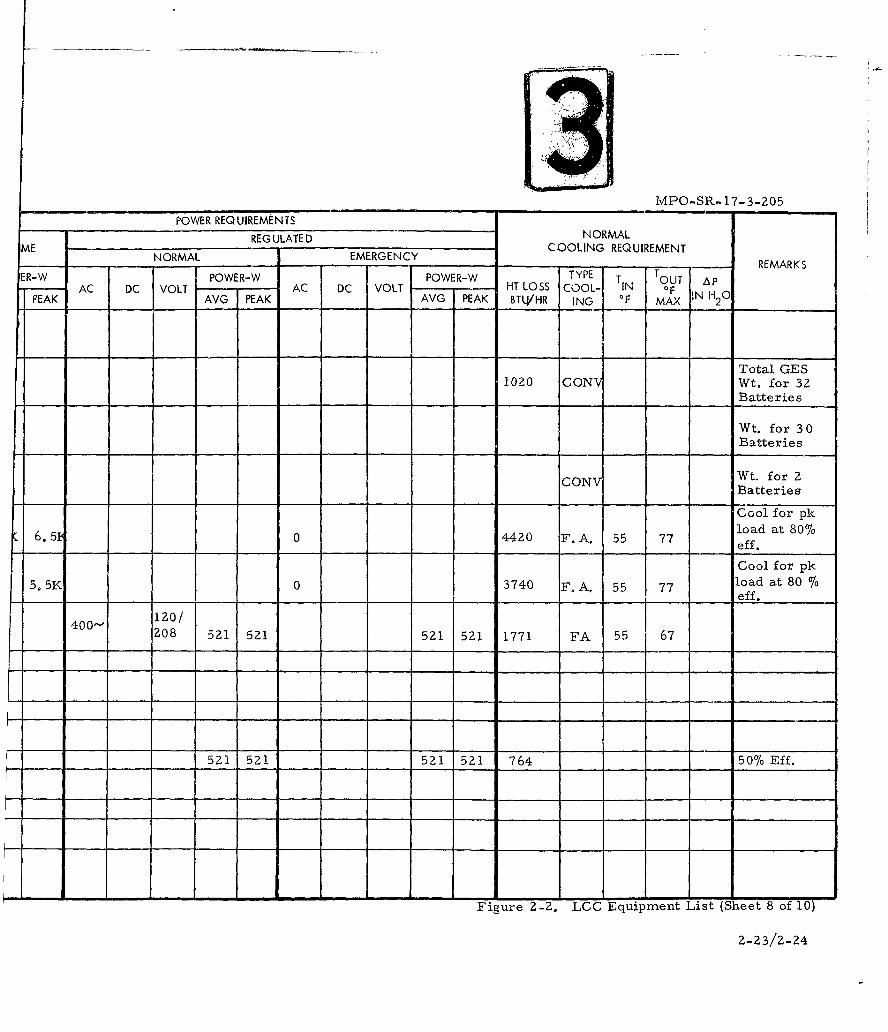
Figure 2-2. LCC Equipment List (Sheet 7 of 10)
2-1/2-22
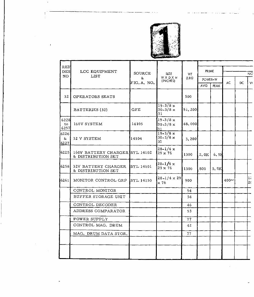
REFDES LCC EQUIPMENT SORE SZ T PRIME NNO LIST & W X D X H (LBS) OWEW
FIG. A. NO. (INCHES)K AC DC V(
3Z OPERATORS SEATS 500
19-3/8 xBATTERIES (32) GFE 30-3/8 x 51,200
31
6228 19-3/8 xto 160V SYSTEM 14105 30-3/8 x 48, 000
62 731____ ______
6226 19-3/8x&3VSYTM14104 30-3/8 x 3,200
6227 31
28-1/4x6ZZ5 160V BATTERY CHARGER SYL 14102 Z9 x 76 1300 Z. OK 6. 5
& DISTRIBUTION SET
28-1/4x6258 32V BATTERY CHARGER SYL 14101 29 x 76 1300 800 5. 5K
& DISTRIBUTION SET
6261. MONITOR CONTROL GRP SYL 14150 Z8-1/4 x 29 900 400'- Z(x 76 2
CONTROL MONITOR 54
BUFFER STORAGE UNIT 54
CONTROL DECODER ___46 __ __
ADDRESS COMPARATOR 53
POWER SUPPLY 77 ______
CONTROL MAG. DRUM 42
MAG. DRUM DATA STOR. _____77 ____ __
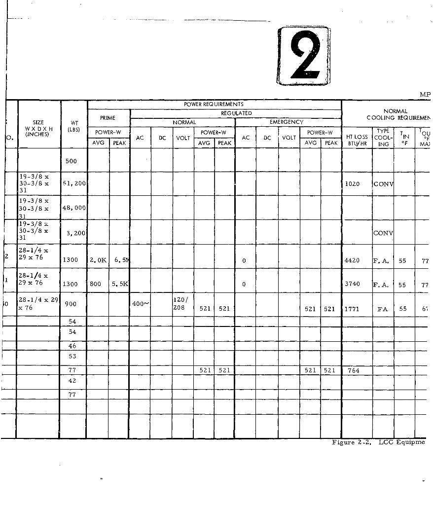
POWER REQUIREMENTSREG ULATE D NORMAL
SIZE WT NORMAL EMERGENCY COOLING REQUIREMEf'
W X D X H (LBS) POWER-W POWER-W POWER-W TYPE T OU(INCHES) AC DC VOLT AC DC VOLT HT LOSS COOL- IN OF
AVG PEAK AVG PEAK AVG PEAK BTLVHR ING IF MAI
500
19-3/8 x30-3/8 x 51,200 1020 CON31
19-3/8 x30-3/8 x 48,0003119-3/8 --
30-3/8 x 3,200 CONV31
28-1/4Z 29 x 76 1300 Z. 0K 6.5 0 4420 F.A. 55 77
28-1/4 xZ9 x 76 1300 800 5.5K 0 3740 F. A, 55 77
0 28-1/4 x9 900 400'- z0/x 76 208 521 521 521 521 1771 FA 55 61
54
54
46
53
77 521 521 521 521 764
42
77
Figure 2-2. LCC Equipme
MPO-SR-17-3-205
POWER REQUIREMENTS
REG ULATE D NORMALNOMLEMREC COOLING REQUIREMENTNORMA -EMERG-NTY- REMARKS
ER-W POWER-W POWER-W TYPE T TOUT AP.- AC DC VOLT AC DC VOLT -HT LOSS COOL- IN OF IN H 01PEAK ______j AVG PEAK AVG PEAK BTLVHR ING OF MAX 2
Total GES1020 CONV Wt. for 32
_____Batteries
Wt. for 3 0Batteries
CONVI Wt, f or 2CONV Batteries
Cool for pk6. 5 0 420 F A. 5 77load at 80%6.5 04420 F.A. 55 ~eff.
Cool for pk5. 5K 0 3740 F. A, 55 7 load at 80 %
________ __ _ __ __ _ __ ___ ___eff.
400- 1Z0/Z08 521 521 521 521 1771 FA 55 67
521 521 521 521 764 ___50% Eff.
Figure 2-2. LCC Equipment List (Sheet 8 of 10)
2-23/2- 24
[
REE PR IMEDES LCC EQUIPMENT SOURCE SIZE WT NOR
NO LIST & W X D X H (LBS) P
FIG. A. NO. (INCHES) POWER-WDC VOAVG PEAK
1626 RADIO SET GFE /SYL Z8-1/4 x 400- Z0(SAC HF RACK) 14013 29 x 76 980 60" 12c
.INTERCON. BOX 50 400 12(ZOE45 R0PE R12(
.ANTELNA CONTROL 20E3. RADIO REC. TRANS. 55 400- 120]
2084 . TEL]E, RKEPEATE R 67, 5 6o- 12C
5. rELE. REPEAT-ER- 67.51 60, 12C
6. AMP. RADIO FREQ. 135 400" 12C(DOUBLE DRAWER) 20E
( LIGHTING (NORMAL RPIE 6OP. I20V
EMERGENCY LIGHTING RPIE 60" 12,
CONVENIENCE OUTLETS
ELECTRICAL RPIE
SURVIVAL LIGHTING SYL 14107
6319 40" xto ESA MOUNTING ASSY SYL 14003 7-5/16"
6324
MCN JACK BOXES SYL A1304
MF ESA 14129
AUDIO ESA 14004
HF ESA 14005
UHF ESA 14036
MPO-SR-17-
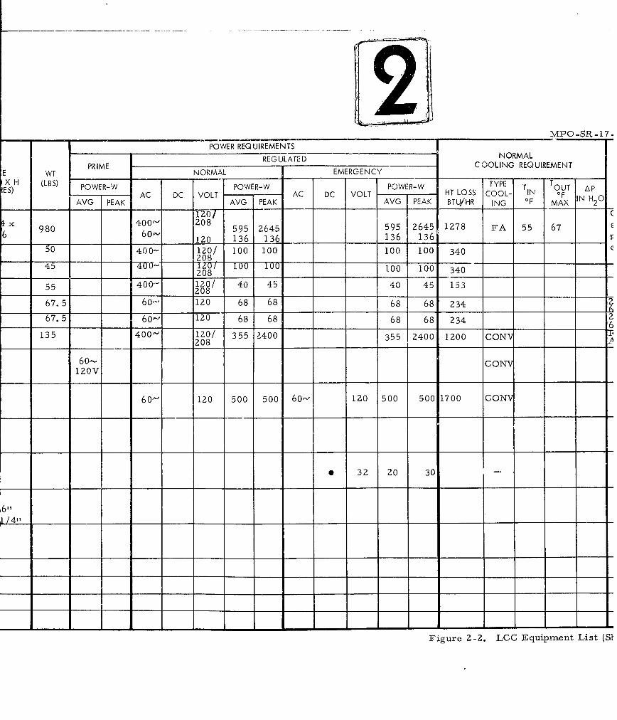
REGULATED NORMALPRIME COOLING REQUIREMENTE WT NORMAL ,EMERGENCY
X (LBS) POWER-W POWER-W POWER-W TYPE OUT ApES)VG AC DC VOLT A AC DC VOLT HT LOSS COOL- IN F IN H 0
V PK AVG PEAK AVG I PEAK BTU/HR ING 'F MAX 2x40' lZO/--"
980400 208 595 2645 595 2645 1278 FA 55 676 60"-'1 120 136 136 136 136 T
50 400- 120/ 10 10 100 100 340 E
1 208 . _ _
55 400 12o/ 40 45 40 45 1531 208
67. 5 60-' 120 68 68 68 68 234 I
67.5 60- 120 68 68 68 68 234 2
135 400- 120/ 355 2400 355 2400 1200 CONV____ _ _208 . .
60,- CONV120V
60- 120 500 500 60- 120 500 500 1700 CONV
6 32 20 30 I
Figur_ _ _ _ , _
- - --- - - - - - - -- -
Figre2-. .GEqipen Lst(S
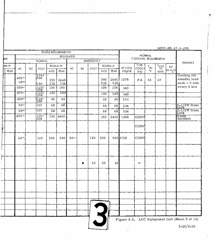
POWE______MNT ____MPO~SR-17 -3 -205
POWER REQUIREMENTSREGULATED NORMAL
ME NOMLEEGNYCOOLING REQUIREMENTNORMAL EMERGENCY-.. REMARKS
ER-W POW['R-W POWER-W TYPE T OUT Ap-- AC DC VOLT AC DC VOLT -T LOSS COOL- IN OFPEAK AVG PEAK AVG PEAK BTU/HR ING OF MAX I20
120 " Cooling for400" Z08 595 2645 595 2645 IZ78 FA 55 67 standby load60" 120 136 136 136 136 peak = 5 min
400- 120/ 100 100 100 100 340 every 6 hrs208
4 ZO 100 100 100 100208 100 340
400"-" 120/ 40 45 40 45 153__ 208
60- 120 68 68 68 68 234 2-1 2W from
6o- 120 68 68 68 68' 234 Z-1/ZW from-- ____6208
400'- 120/ 355 Z400 355 2400 1200 CON 6oom
208 Ambient
CONY
60"- 120 500 500 6o- 120 500 500 1700 CONV
0 32 20 30
Figure Z-Z. LCC Equipment List (Sheet 9 of 10)
2-25/Z-26
PREFDES LCC EQUIPMENT SOURCE SIZE WT PRIME NC
NO LIST & WXDXH (LBS)FIG. A. NO. (INCHES) POWER-W AC DC
AVG PEAK
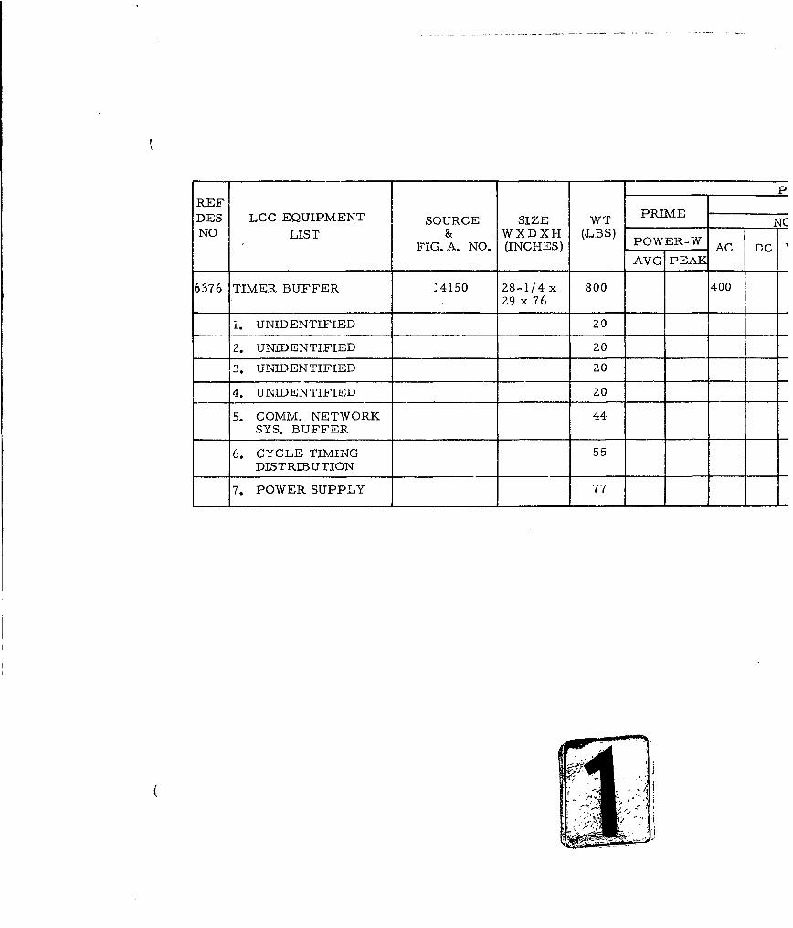
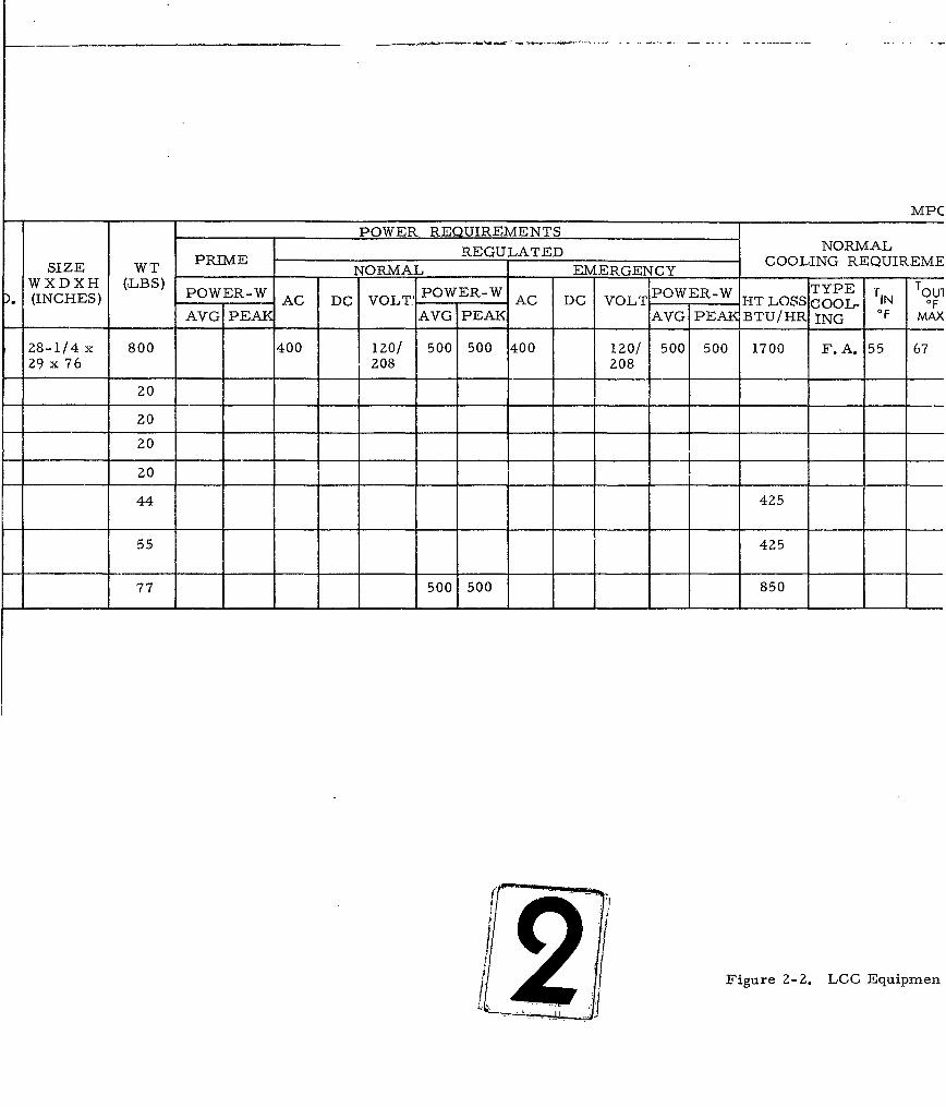
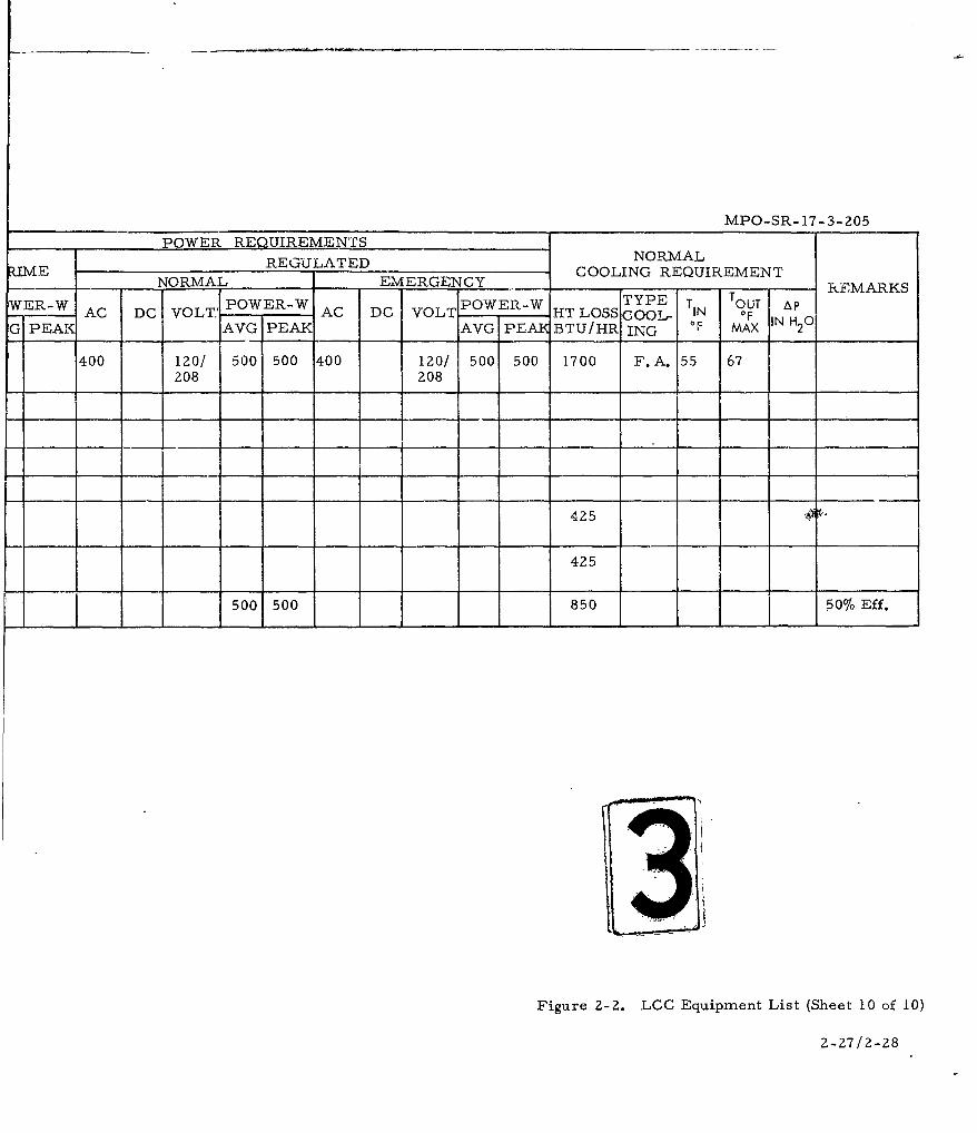
6376 TIMER BUFFER :4150 28-1/4x 800 400
29 x 76
1. UNIDENTIFIED 20
2. UNIDENTIFIED 20
3. UNIDENTIFIED 20
4. UNIDENTIFIED 20
5. COMM. NETWORK 44SYS. BUFFER
6. CYCLE TIMING 55DISTRIBUTION
7. POWER SUPPLY 77
MPCPOWER REQUIREMENTS
REGULATED NORMAL
SIZE WT PRIME NORMAL EMERGENCY COOLING REQUIREM]
WXXH(,BS PWE-WPOERWPOWER-W TYPE T TOUl(INCHES) P ERWAC DC VOLT.' AC DC 'VOLT - -IT LOSS Cool, IN OF
AVG PEAK AAVGIPEA BTU/HR ING OF MAX
28-1/4x 800 400 120/ 500 500 400 120/ 500 500 1700 F.A. 55 67
29 x 76 208 208zo1 k
20
20
20
20
44 425
55 425
77 500 500 850
2 Figure 2-2. LCC Equipmen
MPO-SR- 17-3-205
POWER REQUIREMENTSRIEREGULATED NORMAL
RIME NORMAL_______ D EMERGENCY COOLING REQUIREMENTTYPE T OUT RMARKS
WER-W POWER-W OE-TYET TUTAAC DC VOLT.' AC DC VOLT POWER -W HT LOSS CNOOL F IN
G PE7AI AVG PEAK AVG PEA BTU/HR ING OF MAX "2c
400 120/ 500 500 400 120/ 500 500 1700 F.A. 55 67208 208
425
425
500 500 850 50% Eff.
Figure Z-2. LCC Equipment List (Sheet 10 of 10)
2-27/2-28
MPO-SR- 17-3-205
Power Supply A-
Fault LocatorIndicator
Fault Locator A-3LCF
Cable Pressurization AAlarm
Telephone Repeater A-5
Telephone -6 Repeater
Station Inter- A-7 6208communication
Figure 2-3. Alarm Monitor
2-29
MPO-SR- 17-3-205
AMPLIFIER CONTROL A-1
RF AMPLIFIER
RF AMPLIFIER
UNIDENTIFIED
GENERATOR-SYNTHESIZER A-5
RECEIVER OSCILLATOR
POWER SUPPLY A-7
Figure 2-4. Radio Set (C&S)
2-30
MPO-SR-17.-3-205
Preliminary
Al -Antenna Tuner
UnidentifiedA-
UnidentifiedA-
UnidentifiedA-
Figure 2-5. Antenna Tuner
2-31
MPO-SR- 17-3-204
4)
Power Distribution - 400 Cycle A- I
Power Distribution - 400 Cycle -
Power Distribution - 60 Cycle A-3
Power Distribution - 60 CycleA-
P ow er D istribution - 60 Cycle .A -
Figure 2-6. Power and Distribution
2-32
MPO-SR- 17- 3-2O.5
Terminal Box -A-1_____
Terminal Box -- A-2
Telephone Repeater -A-
Telephone RepeaterA-
Figure 2-7. Junction Box Set
2-33
MPO-SR.- 17-3-205
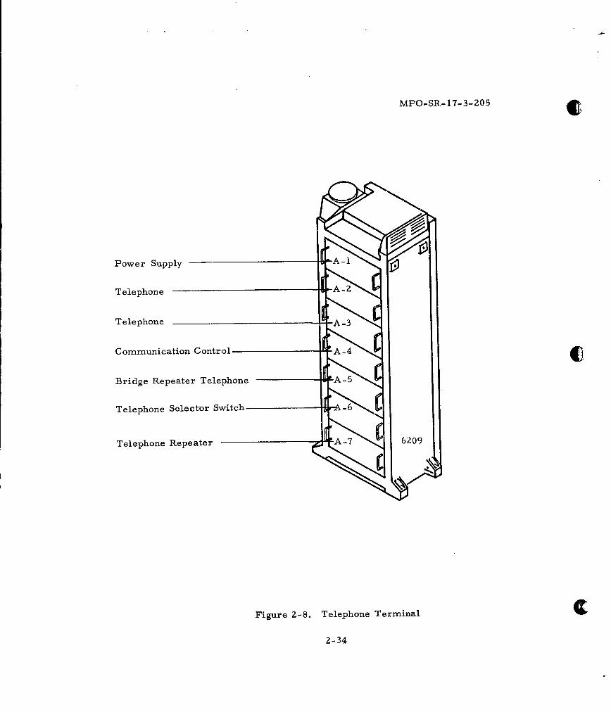
Power Supply
Telephone -
TelephoneA-
Communication Control A-4
Bridge Repeater Telephone A-5
Telephone Selector Switch A-6
T e le p h o n e R e p e a te r A -70
Figure 2-8. Telephone Terminal
2-34
MPO-SR-17-3-205
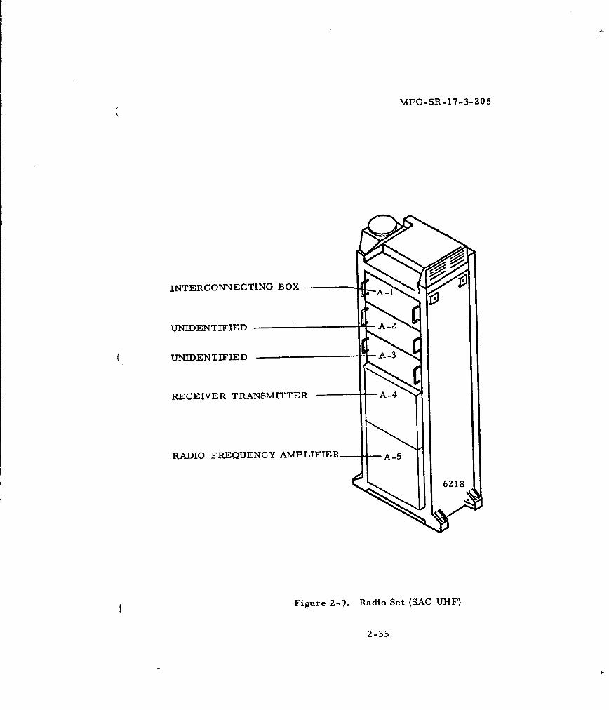
INTERCONNECTING BOX
UNIDENTIFIED
UNIDENTIFIED-A3
RECEIVER TRANSMITTER
RADIO FREQUENCY AMPLIFIER A-5
~6218
Figure 2-9. Radio Set (SAC UHF)
2-35
MPO-SR-17-3-Z05
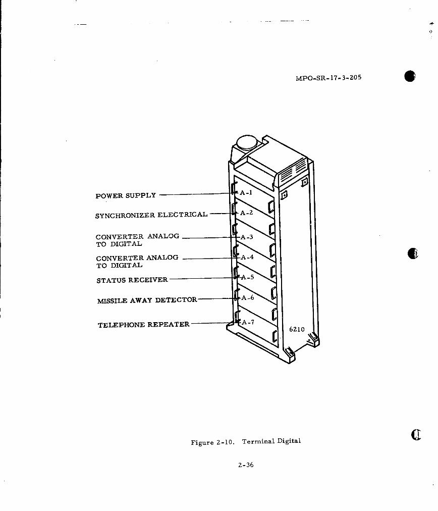
POWER SUPPLY A-1
SYNCHRONIZER ELECTRICAL A-2
CONVERTER ANALOGTO DIGITAL
CONVERTER ANALOGTO DIGITAL
STATUS RECEIVER
MISSILE AWAY DETECTOR -
TELEPHONE REPEATER -" ( - 6Z1O
Figure Z-10. Terminal Digital
2-36
MPO-SR- 17-3-205
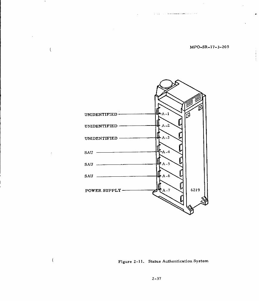
UNIDENTIFIED ' 1
UNIDENTIFIED
UNIDENTIFIED A-3
SAU
SAU
SAU
POWER SUPPLY A-7 6219
Figure 2-11. Status Authentication System
2-37
MPO-SR-17-3-20-5
INTERCONNECTING BOX
ANTENNA CONTROLA-
RADIO RECEIVER A-3_____TRANSMITTER
TELEPHONE REPEATER A4N
TELEPHONE REPEATERA-5
RADIO FREQUENCY -A-6____AMPLIFIER
60
Figure 2-12. Radio Set (SAC HF)
2-38
( MPO-SR-17-3-205
CONTROL MONITOR
BUFFER STORAGE UNIT A-Z
CONTROL DECODER
ADDRESS COMPARATOR
POWER SUPPLY
CONTROL MAGNETIC DRUM
MAGNETIC DRUM DATA STORAGE A-7 6261
Figure 2-13. Monitor Control Group
2-39
MPO-SR- 17-3-205
0
0
0
0
00
o 0
0WU
~4Z 0 4
0 -C4"C
-I 4<4c~c~og 2-40
( MPO-SR-17-3-Z05
POWER DISTRIBUTION SET
UNIDENTIFIED
BATTERY CHARGER 32 VDC
Figure 2-15. 32-Volt DC Battery Charger and Distribution Set
2-41
MPO-SR-17-3-205
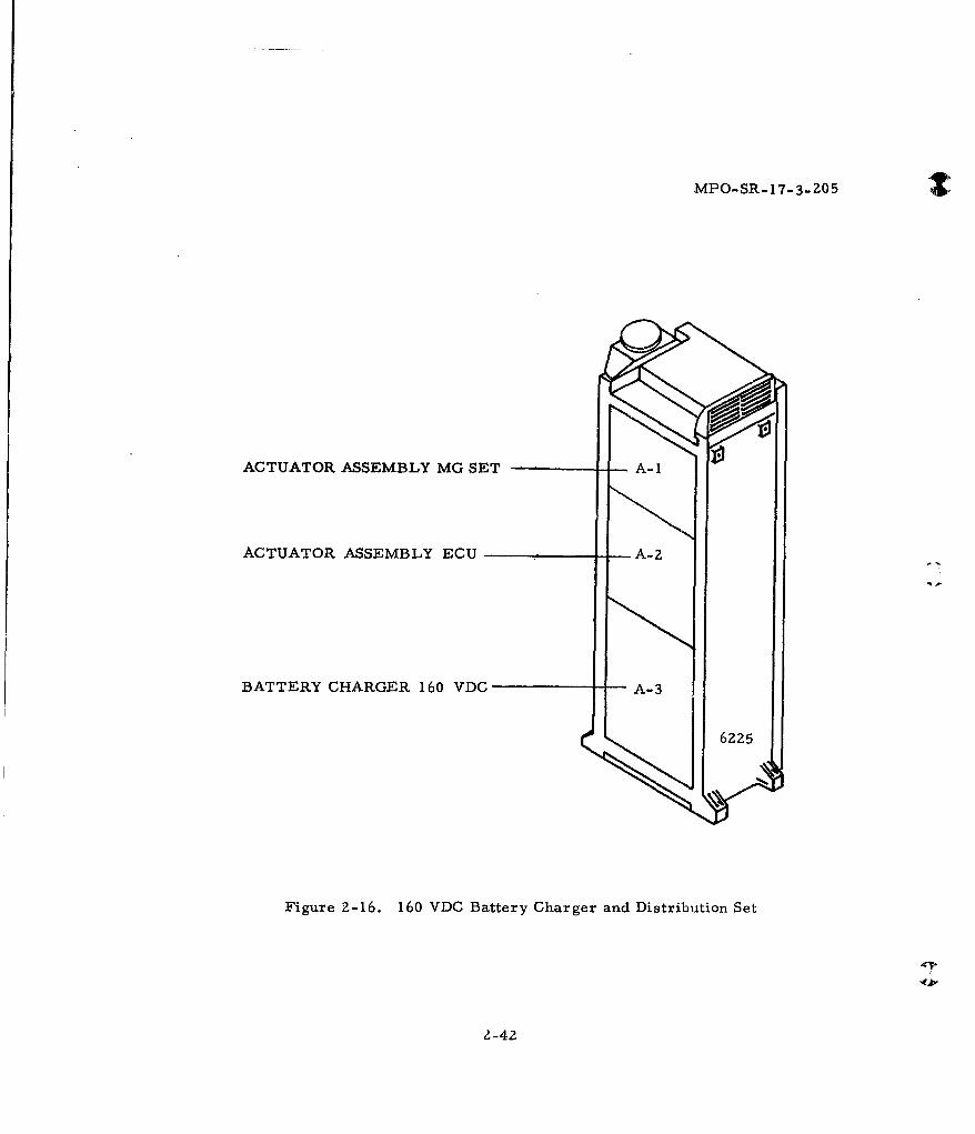
ACTUATOR ASSEMBLY MG SET A-1
ACTUATOR ASSEMBLY ECU A-2
BATTERY CHARGER 160 VDC A-3
6225
Figure Z-16. 160 VDC Battery Charger and Distribution Set
4-4
1-42
MPO-SR- 17-3-205
(O
0
0
0
4
0 0
-4
.1.
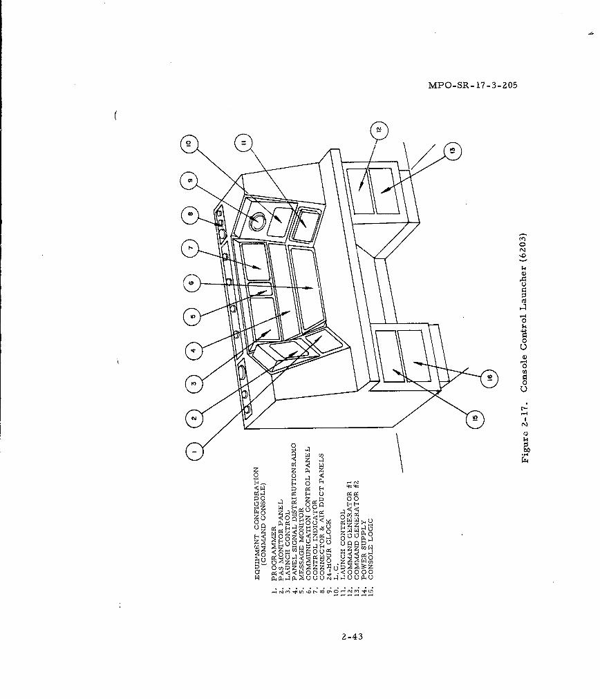
0 00u- 0 -
0 0~ 1-4 Z
r 94 Q P- 02 4E- 4 14
:4. 0 0Q0 0wp
0 u
r~ woou.- ooo~
2-43
MPO-SR- 17-3-205
U
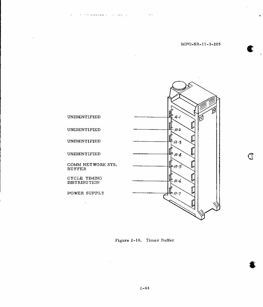
UNIDENTIFIED -
UNIDENTIFIED
UNIDENTIFIED
UNIDENTIFIED
COMM NETWORK SYS.BUFFER
CYCLE TIMINGDISTRIBUTION
POWER SUPPLY P-7
Figure 2-18. Timer Buffer
2
2-44
MPO-SR- 17-3-205
2.3 STRUCTURAL
Within the LCC there shall be provided by others an isolated equip-
ment space capable of supporting the items described on the Sylvania LCC
Equipment List which notes weights of both Sylvania and GFE items.
Primary shock isolation devices for the LCC shall be provided by others.
The storage volume required to contain properties to be furnished
by miscellaneous agencies are noted in paragraph 2. 2.
Hold down devices, essential for secure fastening of contemplated
units of equipment and subsystems to withstand weapons effects, shall be
provided and installed by others. Minimum toe-to-toe clearance between
racks adjacent to consoles shall be 97-1/2" for attachment of console
handling casters.
Bolt hole location drawings will be supplied by Sylvania pertaining
to all unique equipment to be placed within the LCC. Equipment identified
as standard Minuteman racks have a bolt-down configuration as shown on
ICD No. 25-38226 GES Equipment (LF and LCC Installation Envelope and
Cooling).
Base details of Operator's Console are as shown on Interface
Control Drawing No. 25-38250.
The MG set shall be located and mounted by others in accordance
with details shown on ICD Drawing No. 25-38247. Lifting eyes shall be
provided in the room structure for hoisting of the MG Set from its floor
location.
ESA boxes and grou? ding plate plus their hardware fasteners will
be provided by Sylvania. The EMP wall shall be designed by others to
withstand weapons effects and to accommodate the weight and number of
ESA Boxes and the grounding plate required by Sylvania to accomplish the
GES, El isolation function. For EMP wall design purposes, six ESA boxes
will normally be combined into a single module. Each ESA box will weigh
2-45
MPO-SR- 17-3-205
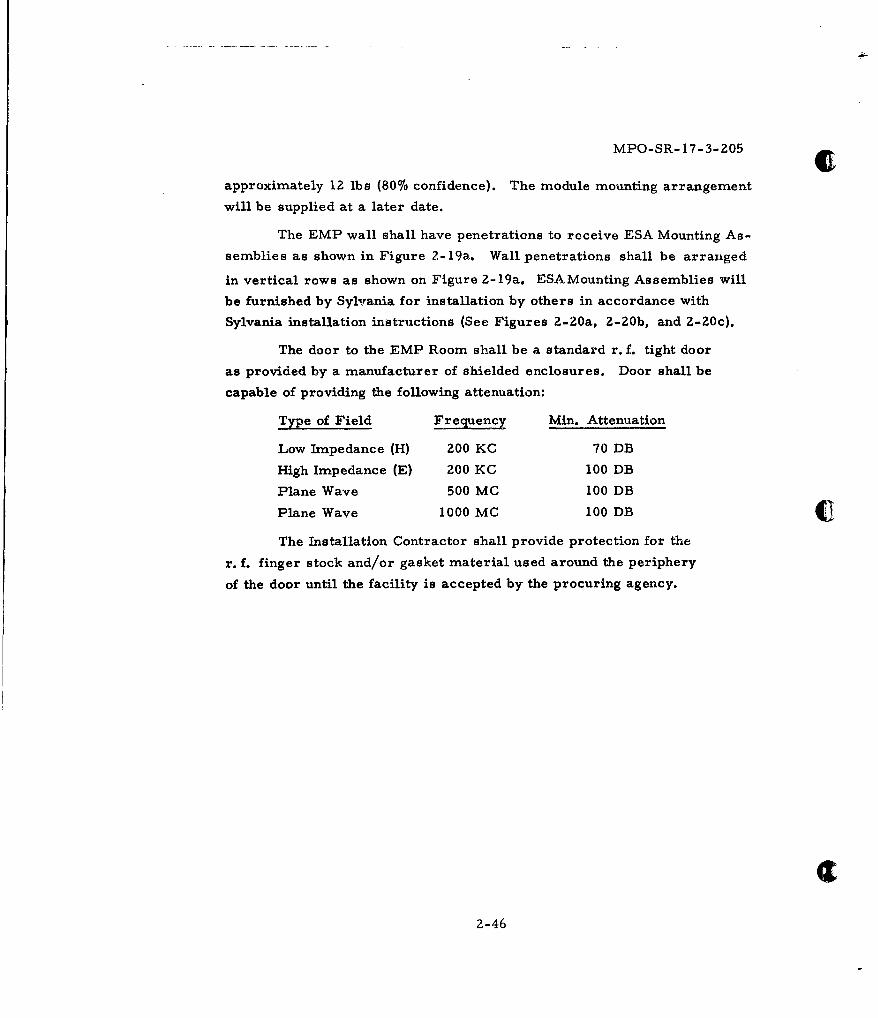
approximately 12 lbs (80% confidence). The module mounting arrangement
will be supplied at a later date.
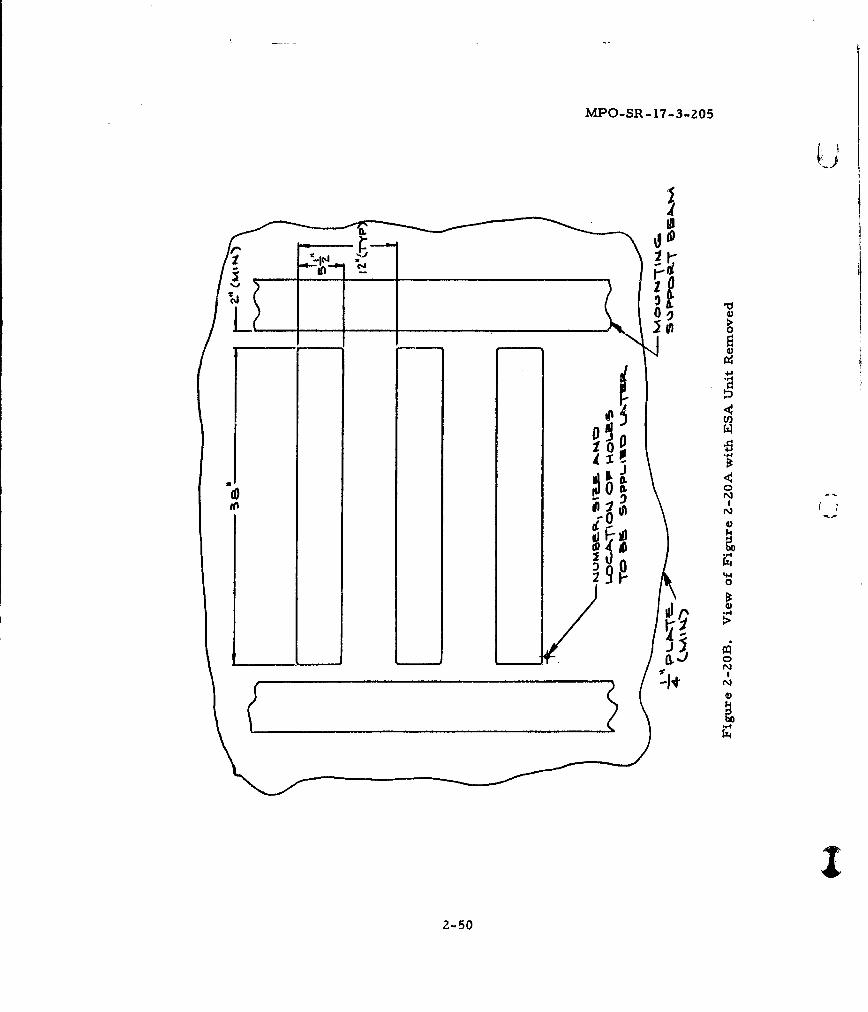
The EMP wall shall have penetrations to receive ESA Mounting As-
semblies as shown in Figure 2- 19a. Wall penetrations shall be arranged
in vertical rows as shown on Figure Z-19a. ESAMounting Assemblies will
be furnished by Sylvania for installation by others in accordance with
Sylvania installation instructions (See Figures 2-20a, 2-20b, and 2-Z0c).
The door to the EMP Room shall be a standard r. f. tight door
as provided by a manufacturer of shielded enclosures. Door shall be
capable of providing the following attenuation:
Type of Field Freq~uency Min. Attenuation
Low Impedance (H) 200 KC 70 DB
High Impedance (E) 200 KC 100 DB
Plane Wave 500 MC 100 DB
Plane Wave 1000 MC 100 DB
The Installation Contractor shall provide protection for the
r. f. finger stock and/or gasket material used around the periphery
of the door until the facility is accepted by the procuring agency.
2-46
MPO-SR- 17-3-205
> cc
0 1-0
tuThIT 044-440
-1
>00
44%jf
12-4
MPO-SR-17-3-205
E S6.
1Y C. TO C.
OCCP -TFELC0O-
xe-ceos 70
C:) =2.4
Figure 2-19B. LCC Conduit Penetrations -EMP RoomInside Elevation-Field End d
2-48
MPO-SR- 17-3-205
Drawing to be Supplied at a Later Date
Figure 2-20A. ESA Interface at EMP Wall
2-49
MPO-SR- 17-3-Z05
0.LV
00
00
2-50
MPO-SR- 17 -3-205
(0
0>01
0
4J
4J)
0
2-512
MPO-SR- 17-3-205
2.4 MECHANICAL
Environmental control of LCC facilities shall be in accordance
with the provisions of BSD Exhibit 62-51 for an occupied, temperature-
controlled installation.
Within the temperature-controlled space, Sylvania GES and GFE
electronic units of equipment shall be cooled by provision of conditioned
air in accordance with BSD Exhibits 62-51 and 62-80. Equipment heat
loads are enumerated on the Sylvania Equipment List applicable to the
LCC (Figure 'Z-).
Individual rack air quantities shall be determined in accordance
with the provisions of BSD Exhibits 62-51 and 62-80 which prescribes an air
temperature of 55PF - Z°F inlet and a maximum outlet temperature of
67*F. During the emergency period forced cooling air may not exceed a
temperature of 90°F leaving the racks. The emergency environmental
control system must be capable of maintaining temperatures of the cooling
air below the 90°F for the required period. Personnel engineering require-
ments recommend that the ambient does not exceed 81'F as stated in BSD
Exhibit 62-79.
A round flexible duct, damper and holding clamp, provided by others
and capable of withstanding weapons effects, shall interface with the inlet
transition duct, the Boeing Company No. BACD40F3, a part of BACC-
60B03-CIFOZ (Minuteman Rack) provided by Sylvania. See Figure Z-1
for guidance as to locations of units of equipment.
The Environmental Control System serving the LCC shall be detail
designed and provided by others in accordance with BSD Exhibit 6Z-80 to
supply the gross air quantity and temperature control as indicated on the
Equipment List, Figure 2-2, for cooling the equipment within the LCC and
maintaining the ambient within limits prescribed in BSD Exhibit 62-79.
2-52
MPO-SR- 17-3-205
Air for cooling must be provided continuously including periods of battery
ope ration.
Distribution duct work, including a flexible make-on to a six-
inch diameter inlet transition duct on all racks shown on ICD No. 25-38226
within the LCC shall be provided by others. Means shall be provided inall air supply ducts for manual modulation of air flow to the individual rack
level in accordance with BSD Exhibit 62-84. Air distribution shall be dev-
eloped to accomodate approximately 1. 5 inches water gage pressure drop
through the forced air cooled racks. Exhausts from the racks will pass
through a Sylvanija provided louvered discharge assembly to the room from
which the environmental control unit draws air by indirect return.
The environmental control system reserve cooling capability within
the LCC shall provide limited-duration operation of the GES complex in
the battery powered mode. The environmental control system shall be
capable of rack cooling during the emergency period. Air exhausted from
units. of equipment is not to exceed 90°F in accordance with BSD Exhibit
62-80.
Beyond Sylvania's designation of locations for plumbing and sanitary
services within the LCC, all considerations of plumbing service shall be
provided by others.
2.5 ELECTRICAL
2. 5. 1 Power - Sylvania has determined the primary power inputs essential
to operate the motor-generator set and battery chargers from commercial
or Deisel generator source. These quantities are shown on Figure 2-2,
LCC Equipment List.
Alternating current power shall be provided by others in accord-
ance with BSD Exhibits 62-4 and 62-77. Power input shall be sufficient
to fulfill the GES equipment requirements established on the Sylvania
2-53
MPO-SR-17-3-205
Equipment List of Figure Z-Z. Additional AC loads for performance of
functions within the LCC, not associated with the GES and Sylvania
integrated GFE, shall remain the responsibility of others.
Power distribution within the Launch Control Center occurring as
an output of the motor generator set, will be a Sylvania responsibility.
2. 5. 2 Distribution. - All GES conduit entering the structure of the LCC
shall be provided by others as specified by Sylvania. Conduit associated
with RPIE items shall be identified by others. Preliminary analysis of
cable tray requirements indicates the use of double tier tray installation,
with trays having a load-carrying capacity of 50 pounds per linear foot for
each tier. The routing and centerline location of the cable trays are
shown in Figures 2-lb and 2-lc. The size of the power cable tray shall
be 12" wide. The wide sections of the signal tray where cable concen-
tration is heavy, shall be 18" wide, and for the narrow sections shall be
12" wide. The cable tray shall be of the ladder type with a cable drop
out for each rack. Each cable drop-out shall be so positioned or other-
wise extended such that the free length of any cable shall not exceed 24"
as measured in a plan view. The mounting height of the signal tray
should be 7'-5" and for the power tray 8'-1". The tolerance in locating
the cable trays shall be + 2 inches for all plan view dimensions and
+ 1/2 inch for installation heights.
Z. 5. 3 Lighting - All lighting requirements shall be in accordance with
BSD 62-79.
2. 5. 3. 1 Normal Operation - Lighting for normal operation within the
LCC shall be provided by others.
Lighting capability in the EMP room is required only during periods
of normal operation. It shall be provided by others. Penetrations of the
EMP wall for power wiring from the interior of the LCC shall be through
an electrical surge arresting device or may be run in a metallic conduit
bonded electrically to the LCCGP.
2-54
MPO-SR- 17-3-205
2. 5. 3. 2 Survival Lighting - Sylvania will provide cables, fixtures and
lamps for connections from the GES protection and distribution rack.
Installation of fixtures shall be by others.
2. 5. 3. 3 Emergency Lighting - For emergency lighting, Sylvania will
provide a power connection device on the protection and distribution rack
and cable to a facilities interface panel, ceiling mounted above the rack.
Emergency lighting circuit shall consist of the RPIE lighting fixtures serv-
ing the Operators' Consoles, powered at all times from the GES 120 volt,
60 cycle regulated power source.
2. 5.4 Grounding, Shielding and Electro-Interference
LCF Grounds - Each Launch Control Facility shall be provided with
the following ground systems to provide static grounding for circuits and
equipment: an electronic equipment reference system, a structure ground-
ing system, a lightning ground system, and a vehicle grounding system.
Each Launch Control Facility shall have two named grounding points
as follows:
1. The LCFGP (Launch Control Facility Ground Point) which isthe point at which an earth ground connection is made.
2. The LCCGP (Launch Control Center Ground Point) which isa common ground point for all items in the LCC. This shallbe located on the inside wall of the capsule.
The lightning ground system shall provide for the connection of all
necessary items to earth ground, and shall provide the primary means
for conducting to earth ground surge currents induced in the system by
lightning.
The water-well casing shall be used as the primary ground means.
Provision shall be made to eliminate electrolytic action at the connection
point of the grounding wires to the LCFGP. The LCCGP, the LCFGP, and
the interconnecting conductors shall survive weapons effects as specified
in AFBSD 62-83.
All signal and power cables and leads shall enter the LCC at or
near the LCCGP. All shields and conduits shall be grounded at this point.
2-55
MPO-SR-17-3-205
All such leads shall enter the LCC directly into a shielded enclosure which
houses the necessary filters, isolating transformers, surge voltage pro-
tection devices, cable pressurization, and sealing means.
2. 5. 5 Conduits - All conduit and pull wires shall be provided by others.
The steel penetrations of the concrete at the LCC into the EMP Room shall
be welded with a continuous weld to the wall liner for grounding purposes.
During installation of all conduits, the outer end shall be capped and marked
above ground with a monument.
Eleven antenna conduits are required from the LCC EMP Room to
the Antenna Farm. See Figures 2-21 and 2-22. These shall be 5-inch
I. D. steel, with the exception of the four conduit to the MF Antenna which
shall be 6-inch I. D. non-ferrous (plastic). MF Antenna conduit shall pro-
vide straight-line routing as further described in Section 8 of this document.
Minimum bending radius for conduit housing the UHF transmission line shall
be six feet. This figure shall become twenty feet if plastic conduit is sub-
stituted on the UHF line.
Five conduits, 5-inch I.D. steel (see Figure 2-19), are required
for the OCCP installation from the penetration of the LCC EMP Room to
within four feet of the surface of the ground. These conduits shall extend
twenty-five (25) feet beyond the fence of the security enclosure and shall
rise at an angle with the horizon not greater than 450 . Long sweep bends
shall be employed for the OCCP conduit, having a radius 36 times the
conduit diameter,
Three conduits, four inches inside diameter steel, are required
from the LCSB to the LCC EMP Room, one each for VHF/MCN and TELCO
and one spare. As the communication facilities in the Support Building are"soft", these conduits will not be required to withstand weapons effects.
There are no critical bending radii for these conduits.
A one inch conduit shall be provided between the compressor-dryer
location in the LCEB and the LCC for the pressure lines terminating in the
EMP Enclosure. Suitable means (one-inch exposed conduit) shall be pro-
vided within the EMP enclosure to convey the pressurizing hose across the
EMP room to within two feet of the OCCP cable entry.
2-56
{: MPO-SR- 17-3-205
All of the above designated conduits must enter the EMP Room,
as shown on Figures 2-21 and 2-22.
A conduit, four inches I. D. shall be provided for the pressuriza-
tion system monitor, alarm and MCN circuits from the LCEB to the LCC.
The conduit for the monitor and alarm circuits and MCN shall not enter
the EMP Enclosure. There is no critical bending radius for this conduit.
2.6 COMMUNICATIONS
2. 6. 1 Inside Cable Communications Plant - Communications is a function
of the GES and shall be accomplished by Sylvania. It is the function of the
Inside Cable Communications Plant of the GES to interface with the Outside
Cable Communications Plant, and to provide the voice and data communica-
tions, which will be transmitted by the Outside Cable Communications Plant,
between the LCF's and LF's. Sylvania shall be responsible for utilization
within the LCC of the display circuits from the LCEB to the LCC relative
to "high air pressure", "low air pressure", and "power on" to compressor
dryer breakers. Placement of MCN devices and cable routing thereto, to-
gether with mounting plate requirements are shown on Sylvania Figures
2-24 and 9-3.
2.7 INTERFACES
Within the LCC, interfaces between Sylvania and others are as
listed herein.
2. 7. 1 Architectural - Data inputs are shown on Sylvania drawings.
2. 7. 2 Structural - Sylvania will provide rack and console hold down
descriptions consisting of bed plate or footing detail drawings. Anchor
bolts, vibration elimination devices, shock isolators and mounting pads,
rails, or pedestals shall be provided by others, incorporating Sylvania
requirements.
2.7.3 Mechanical - To cool electronic equipment, a round flexible duct,
damper and holding clamp capable of withstanding weapons effects shall
2-57
MPO-SR-17-3-205
be provided by others. It shall interface with the Minuteman rack (BACC-
60-BO3ClFO2) provided by Sylvania. (See ICD No. 25-38226).
Sylvania will take no cognizance of plumbing interface within the
LCC beyond a statement of location for devices.
2.7.4 Electrical - Primary power described in paragraph 2.5 shall be
routed to the RPIE Power Panel LCDB by others. Cables from the load
side of GFE circuit breakers on the RPIE Power Panel to battery chargers
and the MG set will be provided by Sylvania, in conduit or wireways pro-
vided by others.
The Sylvania interface is at the load side of the GFE circuit break-
ers in the RPIE Power Panel. At the load side of the GFE circuit breakers,
commercial or stand-by power shall be as specified in AFBSD Exhibit
62-77.
Power service provided by others is required from the LCC to the
HF Hard Transmit Pop-Up Antenna as stated in Sylvania Equipment
List, Figure No. 8-3.
Sylvania interface with Environmental Control Unit for provision
of emergency battery power shall be at the junction box of the Environ-
mental Control Unit.
2. 7.5 Communications - Three conduits shall be provided from the LCSB
to the LCC for communication cables that interface with soft communica-
tions in the LCSB.
Eleven conduits shall be provided from the LCC to the antenna
farm, as specified in paragraph 2. 5. 5 of this document.
Two conduits shall be provided between the LCC and the LCEB.
One conduit will carry the cabling for the maintenance communications
network, and monitor and alarm pairs. The other is for the cable pres-
surizing air line.
2-58
MPO-SR- 17-3-205
The power conduit shall be specified by others for prime power
input to the LCC.
FiVe conduits shall be provided from the LCC to a point 25 feetbeyond the security fence surrounding the LCF for the cable connection
to the LF, and for hardened TELCO cables. Pulling iron shall be provided
in co4unction with the OCCP conduit to permit application of a 1200-pound
pulling stress for placement of OCCP cable in the LCC.
In the above conduit items, the structural penetrations shall beprovided by others. Conduit terminations for GES shall be provided bySylvania for installation by others. (Figures 2-21 and 2-23.) All conduits
shall have pull wires placed when the conduit is inatalled.
2-59
MPO-SR- 17-3-205
4- G" .0, TODRY kIRLIWM
30~~i UHFa-" .0
-J (J
Hr- HkRO LiL,Tvkhk%%ksM-I Covie.O
2-01
MPO-SR-17-3-205
u 4
to g
0
-4 N
u u0N
E4J0Ij>'1 4J
- - 4J 4
0 * .
2-61
MPO-SR- 17-3-Z05
00,0
2-62
MPO-SR-17-3-205
0
bo
00
rj U
2,60
MPO-SR..17-3-205
4 I 0Kj
IIIL
cJop
*w if
0
Alt
2-64
MPO-SR- 17-3-205
LEVEL
SS R- W
±=ZOU4F-2. by'
POR lwzkL7k L O"R
Figure 2-26. Battery Ground-LCC
2-65
MPO-SR -17-3-205
rml -T IN O
PS.CVmh-%4c e Y SYL VAIPOjR /N$TAll4fOJV BY OTHIAS
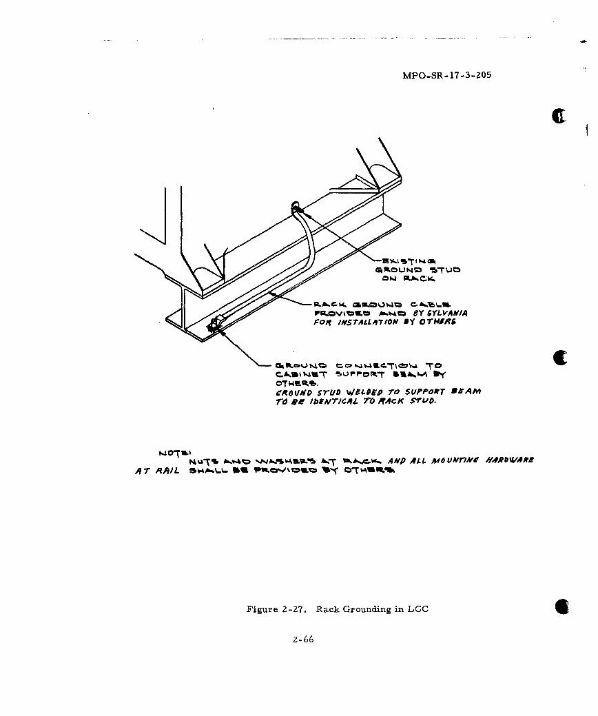
Ck IkftJS= "TC.A.3~v4,mT %OPP-Opt- &IA"tyOTWF4gt.g()oVNDP MILD v/51.DP& rO SVPPOfrT ONAMrd10 * bIA'/c4t ro MRCK STUD.
tA%3Ts Ab"C W Ahr- AMVP ALL MfO UP/T7N #*RU0WA*A7' AA'L WI Wa Qu MNkb
Figure 2-Z7. Rack Grounding in LCC6
2-66
MPO-SR- 17-3-205
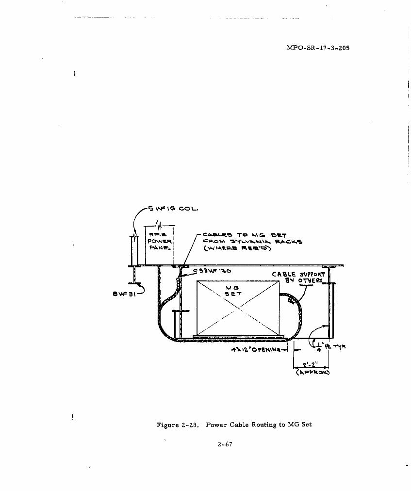
POWEJR Fpo P A 1V p.W.
Figure 2-28. Power Gable Routing to MG Set
2-67
MPO-SR- 17-3-205
SECTION 3
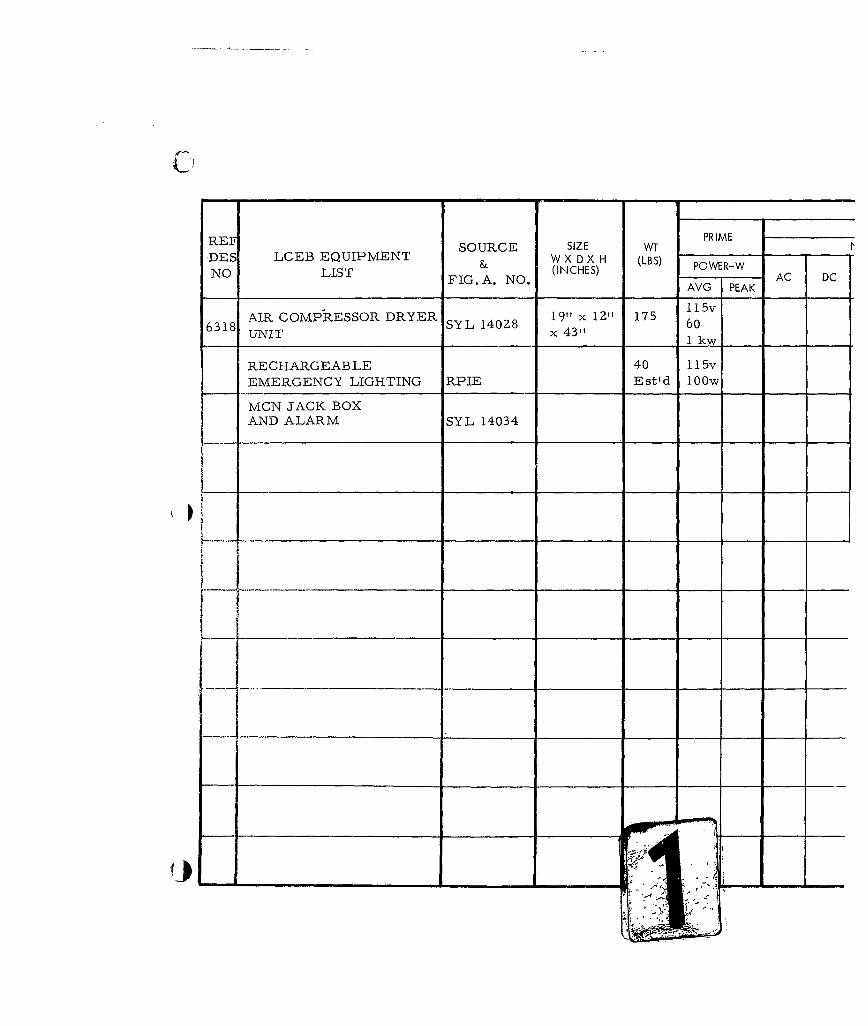
LAUNCH CONTROL EQUIPMENT BUILDING (LCEB)
3.1 FUNCTION
The LCEB is the utilities and environmental control center for
sustaining long duration activity within the adjacent LCC. It shall be
considered an unattended facility with respect to Sylvania-implemented
GES Equipment. Within this structure, Sylvania requires space allo-
cation for placement of a cable pressurization system (as shown on the
LCEB Equipment List, Figure 3-1). Except for Maintenance Communi-
cation Network (MCN) circuits, no additional Sylvania-provided, or
Sylvania-integrated devices are contemplated for location within the
LCEB. This facility shall also serve as a power generation source,
housing the GFE auxiliary generator and the transfer switch equipment
to control the gross power input to the adjacent LCC.
3.2 ARCHITECTURAL
Space availability and access shall be provided within all LCEB's
for pressurization equipment of the size and weight shown on the appli-
cable Sylvania Equipment List (Figure 3-1). Preference for the loca-
tion of the compressor-dryer within an LCEB is not an architectural
constraint, except that access to the entire cabinet shall be provided
for maintenance purposes (Figure 3-1). It is further required that
additional clear space of four inches at sides and rear be provided for
air circulation and bracket attachment.
A refrigerator-type dryer-compressor is contemplated for this
installation; however, there is no requirement for a drain to remove
the water condensed from the intake air since this is accomplished by
re-evaporation into the room.
Routine maintenance imposes a requirement that the cabinet be
accessible for accomplishment of such tasks as lubrication, belt ad-
justments, cleaning or changing strainers and filters, and replacement
of chemical canisters.
3-1
MPO-SR -17-3-205
3.3 STRUCTURAL
Provision shall be made by others for secure fastening of the
pressurization system within the LCEB. Equipment is designed to be
fastened to the wall, and is provided complete with detachable brackets
which bolt to the cabinet. The means of securing these brackets to the
equipment room structure shall be provided by others. For dimensional
drawing pertaining to the placement of wall mounting brackets for the
compressor-dryer, refer to ICD 25-38272. A mounting panel shall be
provided by others for the placement of the pressurization system andfor the MCN jack box and alarm set, for installation by others. Jackbox mounting height centerline shall be approximately 5 feet above the
work platform. See Sylvania supplementary illustrations for fastening
pattern of jack box and alarm set.
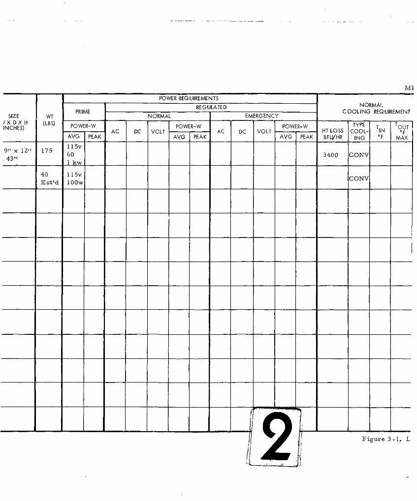
3.4 MECHANICAL
Sylvania will furnish a cable pressurization system complete Cwith self-contained compressor, receivers, distribution manifold and
primary control devices for installation in all LCEB's. The assembly
shall have characteristics as defined on the Sylvania Equipment List(Figure 3-1). Between the LCEB and the LCC a plastic pressure line
and connecting clamps will be provided by Sylvania for installation
by others.
In addition to the above requirement, the LCEB shall be con-
sidered the physical source of environmental (temperature and humi-
dity) control for the adjacent LCC in accordance with the requirements
of BSD Exhibit 62-80. In determining the load summations for these
services, consult Sylvania Equipment Lists in which certain equipment
heat loads are defined.
All sumps and drains shall be provided by others.
3-2
REF SOURCE SIZE WT PRIME
DES LCEB EQUIPMENT & W X D X H (LBS) POWER-WNO LIST FIG. A. NO. (INCHES) PEAK AC DC
19" x 1" 175 11 5v
AIR COMPRESSOR DRYER SYL 14028 191," kw 6061UNIT x 4311 kw
RECHARGEABLE 40 115v
EMERGENCY LIGHTING RPIE Est'd 100w
MCN JACK BOXAND ALARM SYL 14034
LILI _ __ _ __
1......
ml
POWER REQUIREMENTS
REG ULATED NORMA'.
PRIME
C OOLING REQUIREMENT
SIZE WT NORMAL EMERGENCYXDXH (LBS)
TYPET(LBHS)POWER-W POWER-W POWER-W T TOUT
I AC DC VOLT AC DC VOLT HT LOSS COOL, IN OFAVG PEAK AVG PEAK AVG PEAK BTU/HR ING OF MAX
9"31" 60 3400 CONV9" x 111 517
40 115V kONV
Est'd 100w
Figure 3-1. L
14- - - - -
-
MPO-SR- 17- 3-ZOS
POWER REQUIREMENTSREGULATED NORMAL
NORMAL EMERGENCY COOLING_ REQIREEN REMARKS
W POWER-W POWER-W TYPE T T UT APAC DC VOLT AC DC VOLT - -T HT LOSS COOL- TIN OF I
EAK AVG PEAK' AVG PEAK BTU/HR ING OF MAX INH2 01 ______
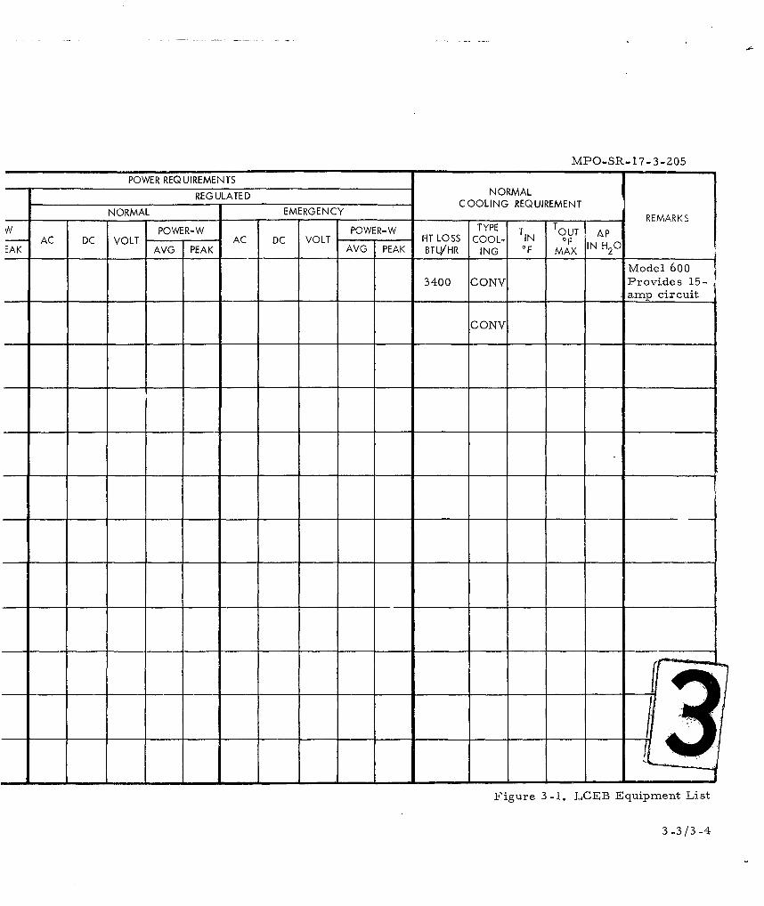
Model 6003400 GONV Provides 15-
_____ ____ ________ ____ ____amp circuit
o ONV
Figure 3-1. LCEB Equipment List
3-3/3-4
MPO-SR-17-3-205
3.5 ELECTRICAL
A power output from the LCEB to the adjacent LCC consisting
of the following shall be provided by others:
1. Major input to Sylvania motor-generator set per SylvaniaEquipment List.
Z. Input to battery chargers, per Sylvania Equipment List.
3. Miscellaneous power inputs for operation of non-criticalequipments in the LCC. This portion covers those inclu-sions by others within the LCC for which Sylvania has nogoverning requirements under the cognizant GES Equipment.
There shall be provided by others such disconnect devices and
conduits within the LCEB as required to make on for the operation of
the Sylvania-furnished pressurizing system.
The compressor-dehydrator requires power as defined in the
Sylvania Equipment List. More stringent regulation than in normally
delivered commercial power is not required. This equipment operates
continuously; however there is no requirementto operate it during the
battery mode of operation.
Conduit provisions from the LCEB to the LCC shall be as follows:
1. A single hardened conduit for prime power input to theLCC from commercial or a Diesel generator source.Size to be determined by others.
Z. A single 4-inch hardened conduit provided and installedby others to contain the pressurization system monitorand alarms and MCN circuit cables provided by Sylvaniafor installation by others.
3. A single one-inch hardened conduit for carrying cablepressurization tubes to be provided by Sylvania for in-stallation by others.
Pressurization of the Minuteman hardened cable is accomplished
by connection of the air line within the adjacent LCC. Monitoring cir-
cuits located at the compressor-dryer device are high pressure, low
pressure and high humidity sensors. Power provided by others is re-
3-5
MPO-SR- 17-3-205
3.6 COMMUNICATIONS
Sylvania will provide for installation by others, cables associated
with pressurization system monitors and MCN circuits from the LCEB
to the LCC. Sylvania will also provide a telephone jack box and alarm
for use in the MCN network for installation by others. Mounting height
shall be approximately 5 feet above the working platform level for ease
of utilization.
The LCEB is not normally manned. Maintenance personnel will
carry telephone headsets to plug into jacks. These headsets will be
compatible with a hard hat and will not require the use of hands for
operation once a connection has been established. Communications
pairs will be carried in the same conduit as the pressurization system
monitor and alarm circuits to the LCC, as stated in Section 2 of this
document. Monitor-alarm pairs from status check points of equip-
ments provided by others and located within the LCEB shall not be
conveyed in the Sylvania-provided cables to the LCC. 4L3.7 INTERFACES
The following interfaces are recognized as being associated
with Sylvania GES items located in the LCEB:
3. 7. 1 Architectural - Minimum space requirements must be provided
for the pressurization equipment as shown on the Sylvania Equipment
List, Figure 3-1. Attachment to the wall of mounting devices for the
pressure dehydrator system shall be provided by others.
3. 7. 2 Structural - The weight and package size of the pressurization
equipment is shown in the Sylvania Equipment List (Figure 3-1).
Anchor bolts, vibration elimination devices, and shock isolation de-
vices shall be provided by others and shall be compatible with dimen-
siong on the Sylvania provided equipment.
3. 7. 3 Mechanical - Sylvania shall provide as a package all valves,
regulators, switches, manifold and gages pertinent to the pressure
3-6
MPO-SR- 17-3-2.05
system located within the LCEB. This shall include a flexible non-
metallic line between the compressor-dryer on the shock-isolated
platform and fixed structural envelope of the LCEB. Any penetration
of the fixed envelope to permit passage of the pressurizing hose to the
LCC shall be provided by others.
3.7.4 Electrical - Electric service connection to the GES compressor
shall be provided by others. Power requirements are detailed on the
Sylvania Equipment List (Figure 3-1). This service is not considered
part of the critical load, but is part of the essential load, to the extent
previously noted in paragraph 3.5. A terminal strip exists in the com-
pressor cabinet for attachment of status monitor lines which form a
part of the MCN network. Power service to the compressor shall be
provided by others. The compressor is provided with a Cornish Wire
Co. cord and plug set CP- 01335-7 having 3-conductor twist lock plug
and 9-foot service cord.
The conduit from LCEB to LCC containing the compressed air
line, status indicating conductors, and voice communication pairs shallbe provided by others with grounding in accordance with BSD Exhibit
62-75 or as otherwise specified by Sylvania.
3.7.4. 1 Commercial Power
Power - Sylvania has no mechanical or electrical interfaces
with the commercial power connections. Wires are required to pro-
vide power from the commercial source to continually trickle-charge
the Diesel starting battery. The mechanical interface is located out-
side of Sylvania's responsibility.
Control - Sylvania has no mechanical or electrical control inter-
faces with the commercial power company.
Monitoring - The RPIE monitor and alarm panels shall monitor
the commercial power. This panel must be provided a signal which
3-7
MPO-SR- 17-3-205
indicates the loss of commercial power. Circuitry to generate this
signal shall be provided by others.
An electrical signal from a commercial power monitor to the
standby power source should be provided in order to supply an out of
tolerance commercial power signal to start the Diesel engine. Cir-
cuitry to generate this signal will be provided by others.
3.7.4.2 Standby Power
Power - Sylvania has no mechanical or electrical interfaces
with the power connections.
3.7. 5 Control, Mechanical and Electrical - Sylvania has no mechanical
or electrical control interfaces with the standby power unit.
The RPIE monitor and alarms panel shall monitor the standby
power. A signal will be provided to indicate the loss of standby power.
Circuitry to generate this signal shall be provided by others.
3.7.6 Communications - Telephone jack boxes and alarms will be in-
stalled as part of the MCN. Sylvania will provide the jack boxes and
alarms for installation by others. Routing of MCN conductor and pres-
surizing hose within the LCEB shall be along the structural edge of the
work platform.
Conduit, provided by others, shall contain a pull wire. Pulling
stress for MCN cable is forty (40) pounds.
Positioning of conduits for the MCN Cable and Pressurization
Line leaving the LCEB enclosure shall be structurally constrained only
to the following extent:
1. The MCN cable when entering the adjacent LCC shall run onthe sway space side of the EMP room structural wall andat a level 8 feet above the walkway level. It shall not termi-nate within the EMP enclosure.
2. The Pressurization Line may be introduced into the EMPenclosure at any selected level within the EMP enclosureabove the walkway level, but shall not interfere with accessto the EMP enclosure via its RF shielded door.
3-8
MPO-SR- 17-3-205
SECTION 4
ACCESS FACILITY
4. 1 FUNCTION
This section pertains to those access. conveyance plants and
facilities lying between the LCC and LCEB, and including entrance
provisions thereto via the LCSB. The primary function with respect
to Sylvania GES shall be to provide access for personnel and handling
of equipments from above ground LCSB to the LCC and LCEB.
An additional function shall be to provide routing of utilities
service to the LCC in the form of primary power, water, sanitary and
LCC environmental source control.
4. 2 ARCHITECTURAL
( Architectural provisions shall consist of access facilities from
the LCSB for personnel and equipment. Equipment sizes and weights
are as enumerated on Sylvania Equipment Lists (Figures 2-1 and 3-1)
applicable to the adjacent LCC and LCEB.
All doorways, aisle space, hatches, and handling facilities shall
be provided and installed by others and will have the size and capability
for handling the largest equipment envelope and weight described on the
above equipment list. Any placement within the access facilities of
equipments provided by others shall in no way impede the handling,
installation, maintenance or removal of Sylvania devices within the
LCF complex.
Sylvania will employ a maximum equipment envelope size (with
shipping containers removed) compatible with existing WS-133A system
constraints. The principal constraints are imposed by the elevator and
the LCC blast door, and dictate that the envelope size will not exceed
36" x 62" x 96".
( Personnel access and safety controiwithin this region shall be
provided by others.
4-1
MPO-SR-17..3-205 24.3 STRUCTURAL
Structural provisions of the interconnecting facilities at the LCF
shall be commensurate with the weight and size requirements of Syl-
vania modules as described in the Sylvania equipment list (Figures 2-1
and 3-1).
All conduits between the LCEB and LCC shall be placed in the
structure of the access facility to assure survival of weapons effects.
These conduits will be used for passage of power, instrumenta-
tion, ventilation air distribution, cable pressurization line, and com-
munication capability. Conduit sizes are identified in Section 2. 5.
All conduit, air duct and power feeders within this passageway
structure shall be provided by others.
Equipment hoisting capability, to the extent implied by equipment
weights given on the Sylvania Equipment List (Figures 2-1 and 3-1),
shall be provided by others as herein defined.
Hoisting and handling capability in the Access Facility shall be
provided at the blast door entry to the LCC. This shall be in the form
of lifting eyes or a demountable crane rail suitably sized and spaced to
permit handling of the Operators' Consoles and MG Set.
It is essential to hoist these modules when installing, and to
block up or crib up to the threshold level of the blast door in order to
permit passage of these devices into the LCC. Suitable 2000 pound
hoists are available from WS-133A systems to perform the lifting
functions.
Special attachable wheel dollies will be provided by Sylvania for
the consoles and will permit their handling once the units are blocked up
to proper rolling height of the blast door mounting sill.
The MG Set will be handled on an existing WS-133A systems wheel
dollie. However, the lifting for horizontal plane alignment with the door
sill requires that hoisting provisions be considered in the Access Facility.
4-2
MPO-SR-17-3-Z05
Suggested spacing of lifting eyes is eight feet to accommodate the
consoles and five feet for the MG Set. Any lifting eye located near the
blast door jamb shall be positioned to give the nearest approach to the
end vertical wall and still permit blast door operation and hanging of
any demountable hoists.
4.4 MECHANICAL
Sylvania imposes no unique mechanical constraints upon the con-
fines of the Access Facility. Sylvania assumes the existence of an en-
vironment of 400F to 1 150F within the interconnecting corridor between
LCEB and LCC.
4.5 ELECTRICAL
The electrical function associated with the Access Facility shall
be to provide an assured conveyance of signal and commercial or Diesel
power between the LCEB and the LCC. Cables and conduits to accom-
plish this shall be provided and installed by others within the structural
confines of the interconnecting corridor facility.
Size of feeders and conduits shall be determined by others from
load requirements established on Sylvania Equipment Lists (Figures Z-1
and 3-1) as a minimum requirement. AU penetrations, flexible transitions
and terminations of power and signal cables and conduits in this vicinity
shall be provided and installed by others.
Signal capability shall be considered to include such items as pres-
surization system status lines, lines to phone jacks connecting the LCC and
LCEB, access door operating circuits, and security devices as yet undefined.
4.6 COMMUNICATIONS
Not applicable.
4.7 INTERFACES
Interfaces within the Access Facility are principally architec-
tural in nature, as already defined above.
4-3
MPO-SR-17-3-205
SECTION 5
LAUNCH CONTROL SUPPORT BUILDING (LCSB)
5. 1 FUNCTION
The primary function of the LCSB is to support the LCC under
normal operating conditions and to provide controlled entry to the
Access Facility for personnel and equipment. As such, it provides
convenience services to the LCC. It should be noted that all interest
in the total LCF area is directed toward sustaining the activity within
the LCC as the focal point of the Ground Electronics System complex.
5.2 ARCHITECTURAL
The commercial telephone company servicing the area in which
the LCF is located will require a closed 10' x 10' area with a ceiling
clearance of 9' (minimum) inthe LCSB. Within this closed area, the
TELCO will place certain equipment as shown on Figure 5-1, the
LCSB Equipment List. In the design of this closed area attention shall
be given to the height of these racks, for access to the room, and
placing the TELCO equipment. Certain GFE to be integrated by Syl-
vania shall be installed by others in a separate area immediately adja-
cent to the TELCO area. GES equipment in the LCSB is also listed on
the LCSB Equipment List, Figure 5-1.
Principal access to the LCC and LCEB is through the LCSB.
It is a Sylvania requirement that the design of the LCSB be such that
no impediment be placed on handling of equipment destined for passage
through the LCSB. Sizes and weights of tiese Sylvania equipments are
shown in Figures 2-1 and 3-1.
5.3 STRUCTURAL
Within the Launch Control Support Building, as a minimum, the
TELCO Area floor shall be capable of bearing a static load of two
hundred pounds per square foot.
5-1
MPO-SR- 17-3-205
5.4 MECHANICAL
VHF radio utilizes room ambient air for cooling and does not
require connection to the central facility cooling devices.
5.5 ELECTRICAL
Two 4-inch conduits are required from the TELCO Area in the
LCSB to a point 25 feet beyond the security fence. These conduits shall
be installed to a depth of three feet. The ends shall be capped and a suit-
able marker placed to indicate where the conduit is located. Pulling wire
.shall be left in the conduits.
A single four-inch conduit shall be placed from the TELCO area
through the exterior wall at the roof of the LCSB. This conduit shall be
capped and a pulling wire installed. Another single two-inch conduit
shall be placed from the GES area of the LCSB to the roof of the LCSB
for passage of the VHF antenna lead.
A single two-inch interior conduit shall be installed from the
security area to the GES-TELCO area. This conduit shall be for VHF
control, signaling and communication.
Three conduits, four inches inside diameter, are required from
the LCSB to the LCC EMP room for utilization as indicated in Section
2.5.
Two 2-inch conduits are required from the TELCO room to LCF
Antenna Plot to contain monitoring lines from H. F. pop-up antennas.
Refer to LCF Conduit Plan, Figure 2-23 for general routing.
5.6 COMMUNICATIONS
Communications between the LCSB and the LCC will be provided
by Sylvania as part of the MCN cable function. Communications between
the LCSB and the SMSB shall be provided by TELCO.
5-2
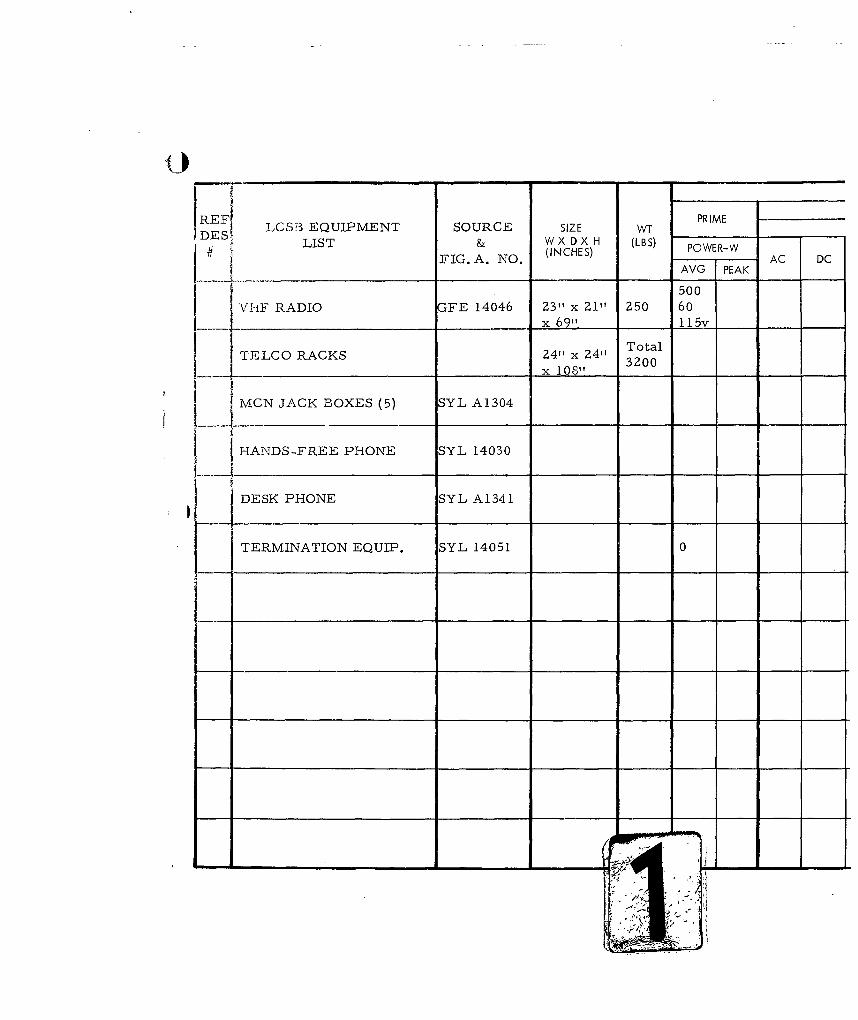
REF LCSF3 EQUIPMENT SOURCE SIZE WT PRIME
DES i LIST & W X D X H (LBS)
FIG. A. NO. (INCHES) POWER-W AC DCFAVG PEAK
500
VIiF RADIO GFE 14046 23" x 21" Z50 60
__x 69". 115v
TELCO RACKS 3420 x 04 Total
MCN JACK BOXES (5) SYL A1304
HANDS-FREE PHONE SYL 14030
DESK PHONE SYL A1341
TERMINATION EQUIP. SYL 14051 0
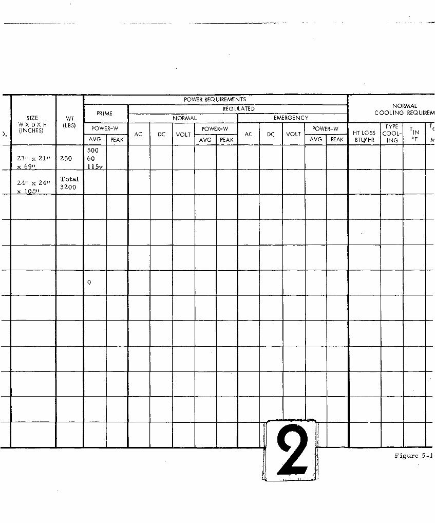
POWER REQUIREMENTS
REGULATED NORMALPRIME C OOLING REQUIREWSIZE WT NORMAL EMERGENCY
W X D X H (LBS) ... TY ET(INCHES) POWER-W POWER-W POWER-W TYPE T T(AC DC VOLT AC DC VOLT HT LOSS COOL- TIN
AVG PEAK AVG PEAK AVG PEAK BTU/HR ING OF IV
500
Z3" x 21" Z50 60
x 69" 115v
TotalZ4" x Z4" 3200
x 1081, 3ZOO1 08"
0
21Figure 5-1
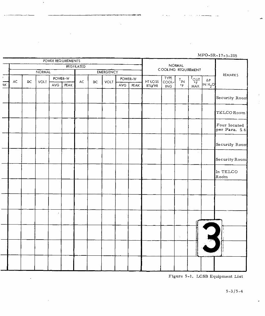
MPO-SR...17..3-205
POWER REQUIREMENTS NRA
NORMAL MERGENC COOLING REQUIREMENTNORML EMRGENY TYE TREMARKS
POWER-W POWERl-WYP T T AAC DC VOLT AC DC VOLT HT LOSS COOL- TIN OUT IN 0kKAVG PEAK AVG PEAK BTU/HR ING OF ~MAX IH 2 0
Security Roor
TELCO Roomn
Four locatedper Para, 5. 6
Security Roor
Security Room
In TELCO____ ________ ____ ____Room
Figure 5-1. LCSB Equipment List
5-3/5-4
MPO-SR- 17-3-205
Sylvania will provide five (5) MCN jack boxes for placement by
others as shown on the LCSB MCN Placement Figure. Per direction
from BSD four jack boxes are located as follows:
(1) heating equipment room
(2) water treatment room
(3) garage
(4) environmental systems equipment room.
The fifth jack box is located in TELCO room.
MCN jack boxes shall be mounted 42 to 48 inches off the floorfor ease of utilization.
There are no conduit requirements associated with these jack
boxes. There is likewise no requirement to utilize the grounding studs
on the boxes placed in the LCSB.
5.7 INTERFACES
Within the LCSB, interfaces between GES and others are listed
below.
5. 7. 1 Architectural - Space for TELCO and other GES equipment is
noted in Sections 5. 2 and 5. 3.
5. 7. 2 Structural - Sylvania shall specify mounting details for GES
equipment within the LCSB. Mounting devices shall be provided and
installed by others. There is no requirement for equipment installed
in the LCSB to withstand weapons effects.
5. 7. 3 Electrical - Convenience outlets and lighting shall be sufficient
to support the TELCO Equipment and GES equipment housed in the
LCSB and to support maintenance equipment.
5.7.4 Communications - Sylvania will interface with TELCO and will
integrate other GES equipment in the LCSB via conduits described under
the electrical requirements of this section.
5-5
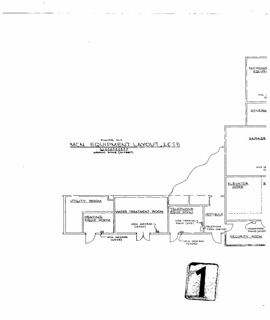
V LRO) UM
G E N F- R
mcmX EC) P~kT\ZYOUWL-T Csi%
UCIJ JA
ELE-VA.DR
UTILITY RCOCA
WN A XE R T R k -rM F-MT Pk(O I A E QU IP R O O K E 5 U
EfTERM, ckstm
ECURIT- ~ Q
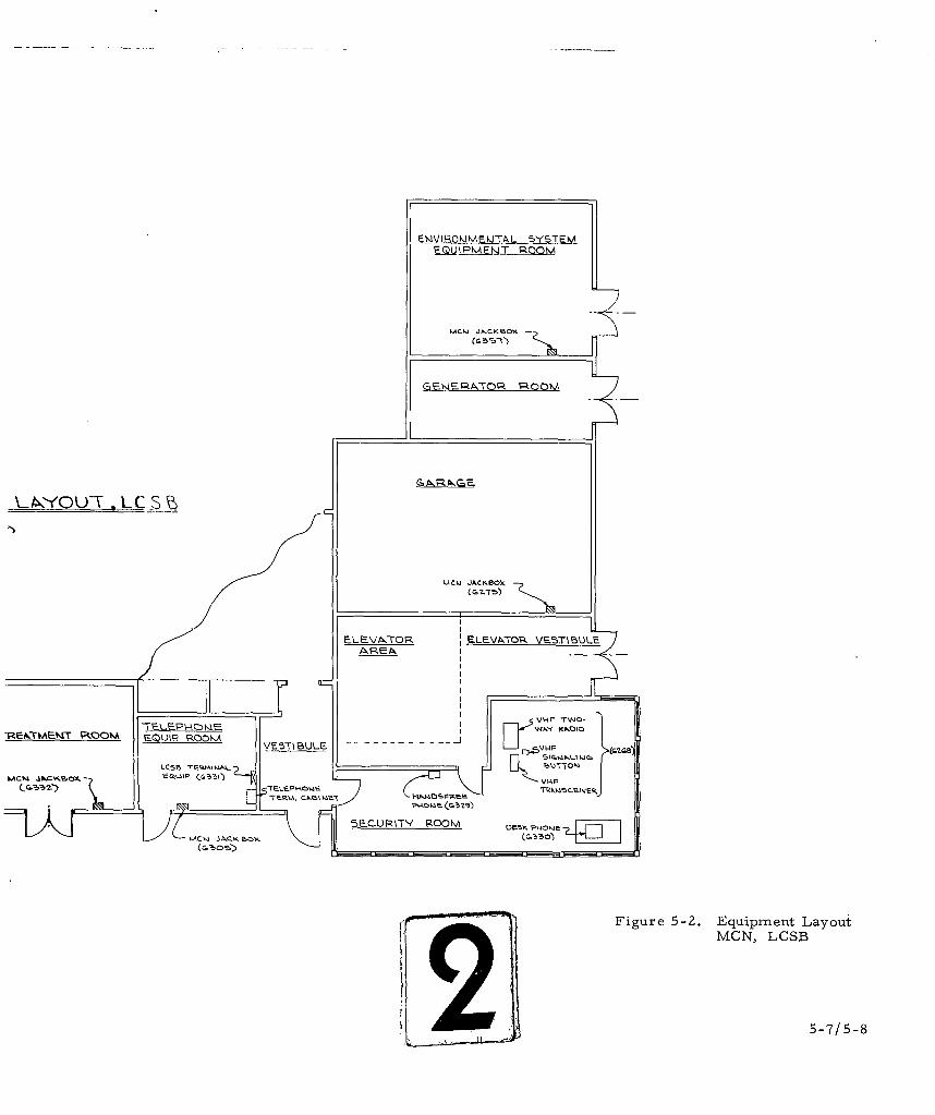
I WNR IHQMi~E~kiTL 5YSTEMVEZQLPAE-T RQ
UcQJ JCKRO"(
~LEVATOR LEVP~.7lk VE5TIBULE-
RE~lE'T~~VE571 BULE E -VPP-wo
LC5iN 7F~k~W.. 4M
VAF
SECURM-W Room O FOH P 0 HV]
Figure 5-2. Equipment LayoutMCN, LGSD2 5-7/5-8
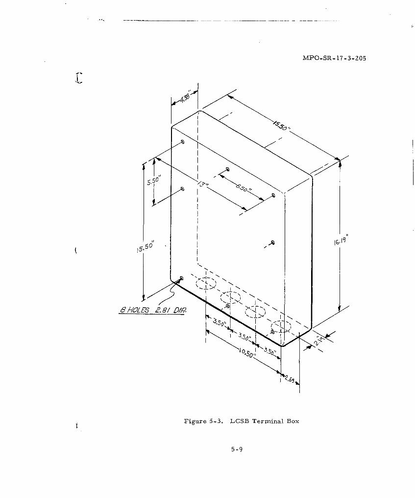
MPO-SR-17-3-Z05
(5-9
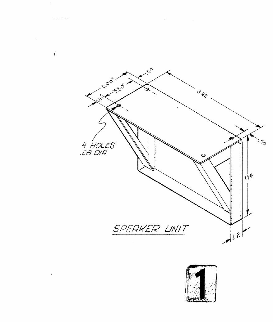
6'0
4HL5P§AR£t/
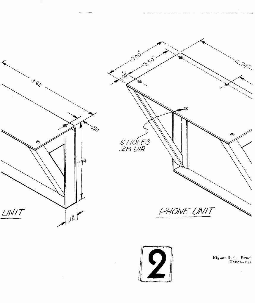
-All/T PY/OM 6/A'! F
I Figure 5-4. Brac&Hands -FrE
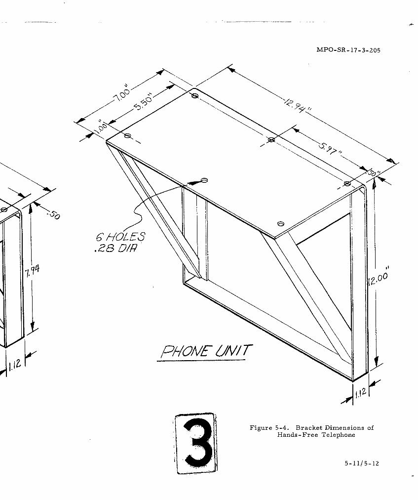
MPO-SR- 17-3-205
Figure 5-4. Bracket Dimensions ofHands-Free Telephone
5-11/5-12
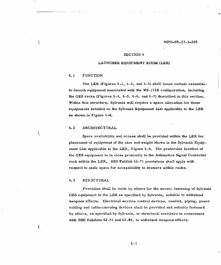
(MPO-SR-17-3-205
SECTION 6
LAUNCHER EQUIPMENT ROOM (LER)
6.1 FUNCTION
The LER (Figures 6-1, 6-2, and 6-3) shall house certain essential-
to-launch equipment associated with the WS-133B configuration, including
the GES racks (Figures 6-4, 6-5, 6-6, and 6-7) described in this section.
Within this structure, Sylvania will require a space allocation for those
equipments detailed on the Sylvania Equipment List applicable to the LER
as shown in Figure 6-8.
6. z ARCHITECTURAL
Space availability and access shall be provided within the LER for
placement of equipment of the size and weight shown in the Sylvania Equip-
ment List applicable to the LER, Figure 6-8. The preferable location of
the GES equipment is in close proximity to the Autonetics Signal Converter
rack within the LER. BSD Exhibit 62-71 provisions shall apply with
respect to aisle space for accessibility to drawers within racks.
6.3 STRUCTURAL
Provision shall be made by others for the securd fastening of Sylvania
GES equipment in the LER as specified by Sylvania, suitable to withstand
weapons effects. Electrical service control devices, conduit, piping, power
cabling and cable-carrying devices shall be provided and suitably fastened
by others, as specified by Sylvania, to structural members in consonance
with BSD Exhibits 62-51 and 62-83, to withstand weapons effects.
6-1
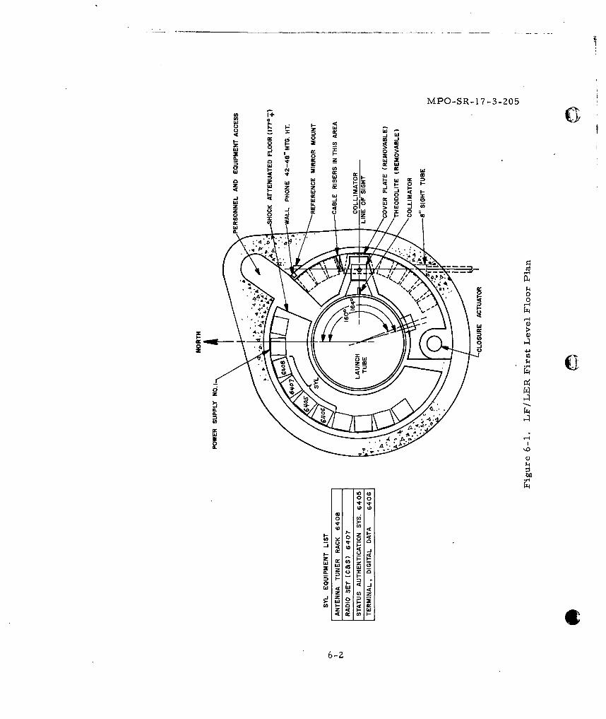
MPO-SR-17-3-205
a4 >jbco 0 0~
zL w 0>T9 z z w0
w w jz 5eJ 00
z 0 1
>Iwj
0- 0 w 2 0 xI
0.'
LO0
:cc
Id 44
x oz
0-0 40to I(D
4QD )1
6-
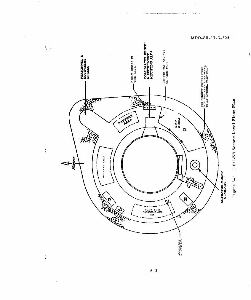
MPO-SR- 17-3-205
CCA
2r,-4
.j 0
44
0-3
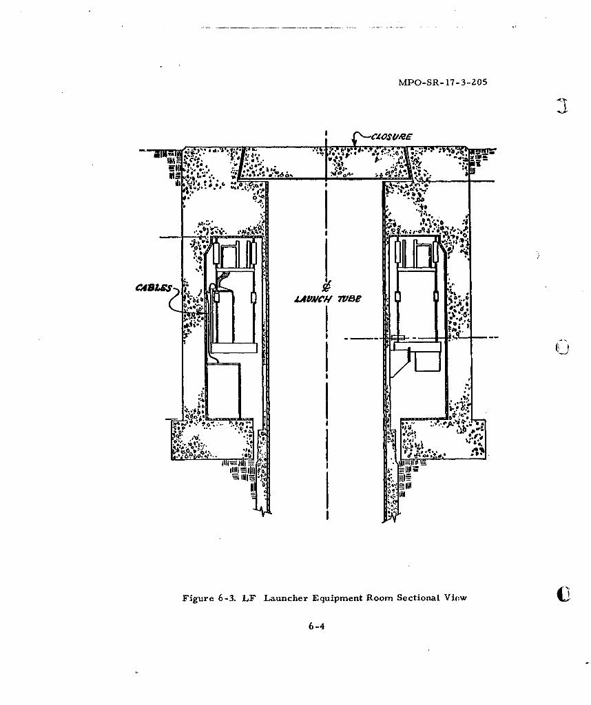
MPO-SR- 17-3-205
.i o
: a
I4VINII MAW
Figure~~~~~~~~~~q 6-dL anhrEupmn omScinlVo
6-4
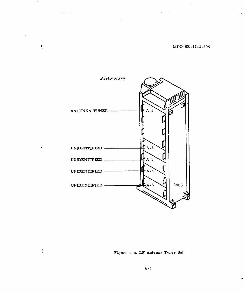
(. MPO-SR-17-3-205
Preliminary
ANTENNA TUNER
UNIDENTIFIED -
UNIDENTIFIEDA-
UNIDENTIFIED -
UNIDENTIFIED -A 5 6408
( Figure 6-4. LF Antenna Tuner Set
6-5
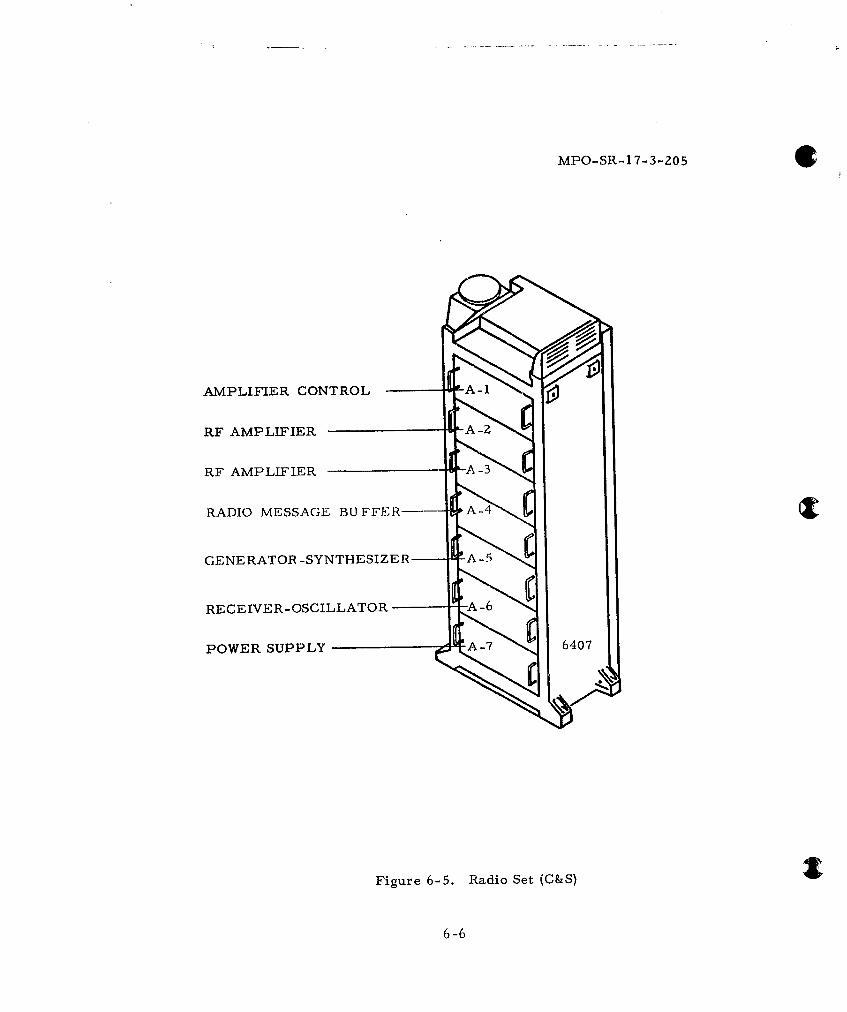
MPO-SR-1 7-3-205
AMPLIFIER CONTROL
RF AMPLIFIER A
RF AMPLIFIER -3
RADIO MESSAGE BUFFFER-- A-4
GENERATOR -SYNTHESIZER A-5
RECEIVER- OSCILLATOR -
POWER SUPPLY 6407
Figure 6-5. Radio Set (C&S)
6-6
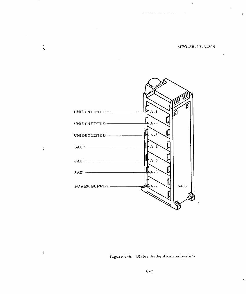
MPO-SR- 17- 3-,205
UNIDENTIFIED
UNIDENTIFIED
UNIDENTIFIED A-3
SAU
SAUA-
SAU -6
POWER SUPPLY A760
Figure 6-6. Status Authentication System
6-7
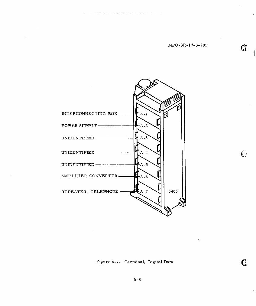
MPO-SR-17-3-205
INTERCONNECTING BOX A
POWER SUPPLY -2
UNIDENTIFIED -3
UNIDENTIFIED
UNIDENTIFIED A-5
AMPLIFIER CONVERTER -6
REPEATER, TELEPHONE A-7 6406
Figure 6-7. Terminal, Digital Data
6-8
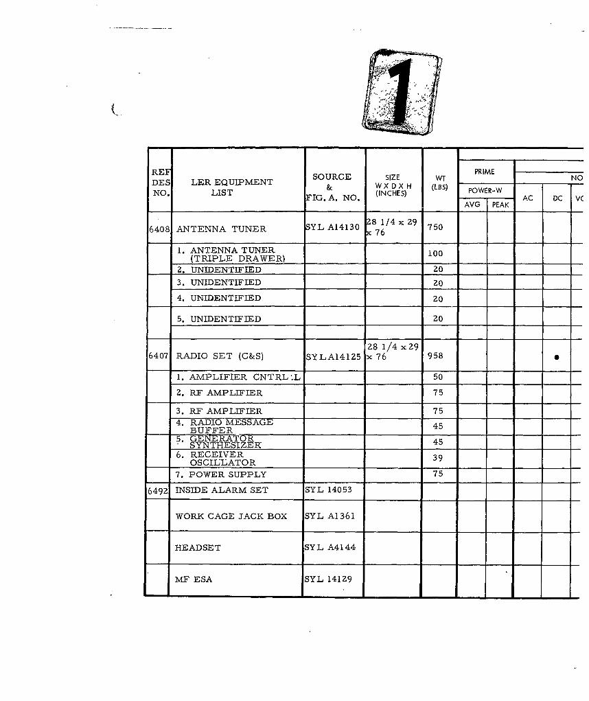
RE PRIMEREF SOURCE SIZE WT PRIME NODES LER EQUIPMENT & W X D X H (LBS)NO. LIST FIG. A. NO. (INCHES) POWER-W AC DC V
AVG PEAK
28 1/'4 2 96408 ANTENNA TUNER SYL A14130 Z 76 7506408 76
1. ANTENNA TUNER 100(TRIPLE DRAWER) 100
2. UNIDENTIFIED 20
3. UNIDENTIFIED 20
4. UNIDENTIFIED zo
5. UNIDENTIFIED 20
28 1/4 x 296407 RADIO SET (C&S) SYLA14125 x 76 958
1. AMPLIFIER CNTRL .L 50
Z. RF AMPLIFIER 75
3. RF AMPLIFIER 754. RADIO MESSAGE 4
BUFFER 45
5. GENERATOR 45SYNTHESIZERI46. RECEIVER 39
OSCILLATOR 39
7. POWER SUPPLY 75
6492 INSIDE ALARM SET SYL 14053
WORK CAGE JACK BOX SYL A1361
HEADSET SYL A4144
MF ESA SYL 14129
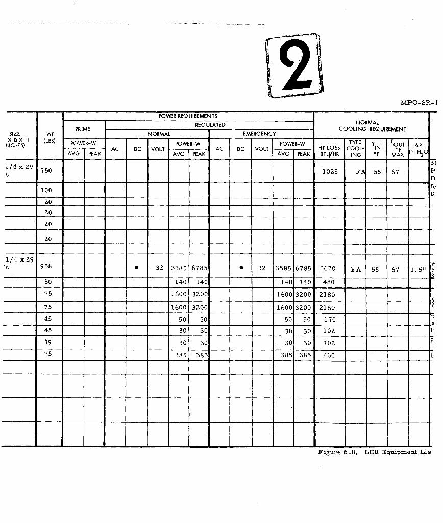
MPO-SR- 1
POWER REQUIREMENTSREG ULATED NORMAL
PRIME C OOLING REQUIREMENTSIZE WT PRIME NORMAL EMERGENCY
X D X H (LBS) TYPETNCHES) POWER-W POWER-W POWER-W TOUT ApAC DC VOLT AC DC VOLT HT LOSS COOL- N OFAVG PEAK AVG PEAK AVG PEAK BTLI/HR ING 0F MAX IN H20
6/4x29 750 1025 FA 55 67 P.6 _D
fc100 _R
20
20
1/4 x 29'6 958 0 32 3585 6785 0 32 3585 6785 5670 FA 55 67 1.5" 5
50 140 140 140 140 480
75 1600 3200 1600 3200 2180
75 1600 3200 1600 3200 2180
45 50 50 50 50 170
45 30 30 30 30 102
39 30 30 30 30 102 -
75 385 385 385 385 460 6
Figure 6-8. LER Equipment Lis
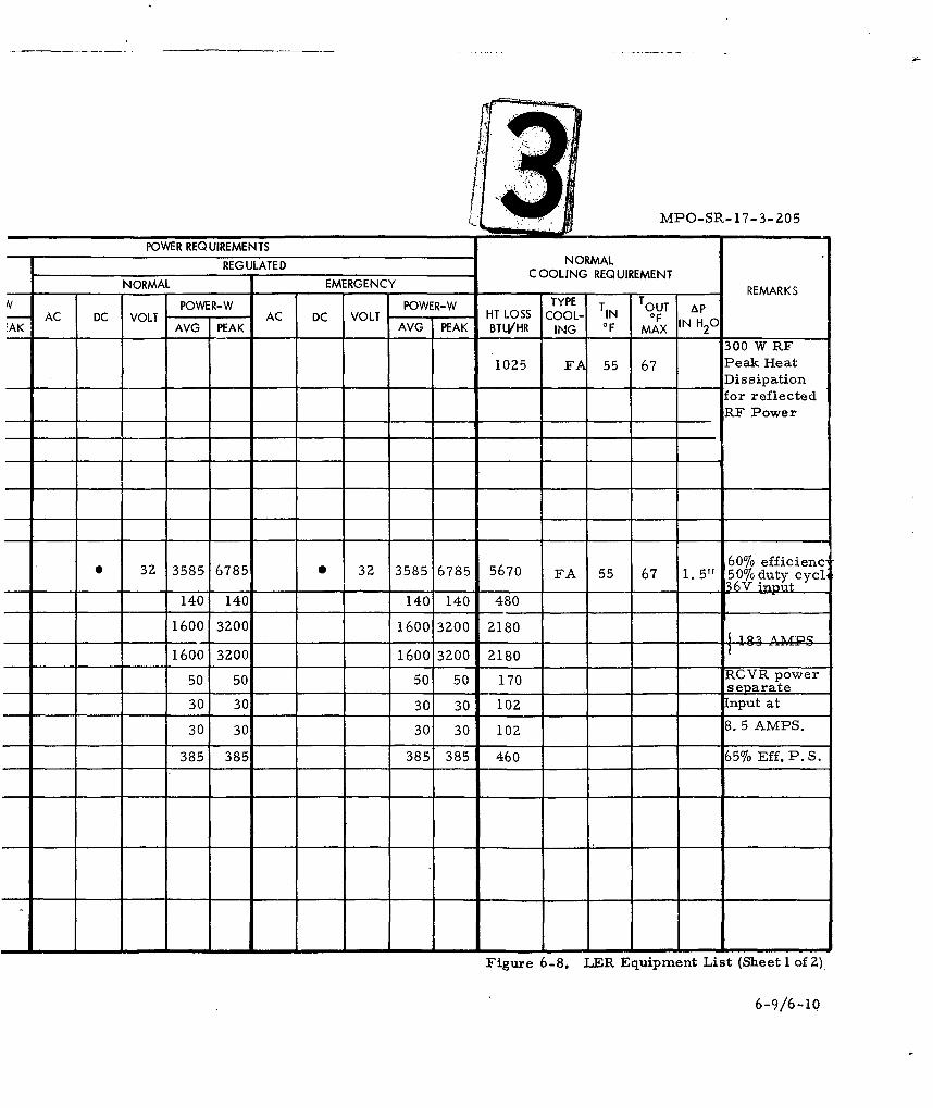
MPO-SR-17-3-205
POWER REQUIREMENTSREGULATED NORMAL
COOLING REQUIREMENTNORMAL EMERGENCY REMARKS
v POWER-W POWER-W TYPE T OUT ApAC DC VOLT AC DC VOLT HT LOSS COOL- IN OF
:AK AVG PEAK AVG PEAK BTLVHR ING OF MAX IN H2 0300 W RF
1025 FA 55 67 Peak HeatDissipationfor reflectedRF Power
60% efficienc"3Z 3585 6785 S 32 3585 6785 5670 FA 55 67 1.5" 50%b duty cyclI36V nut
140 140 140 140 480 -
1600 3200 1600 3200 2180 1 0 ' OC
1600 3200 1600 3200 218050 50 50 50 170 RCVR power
separate
30 30 30 30 102 Input at
30 30 30 30 102 8.5 AMPS.
385 385 385 385 460 657o Eff. P.S.
Figure 6-8. LER Equipment List (Sheet 1 of Z)
6-9/6-10
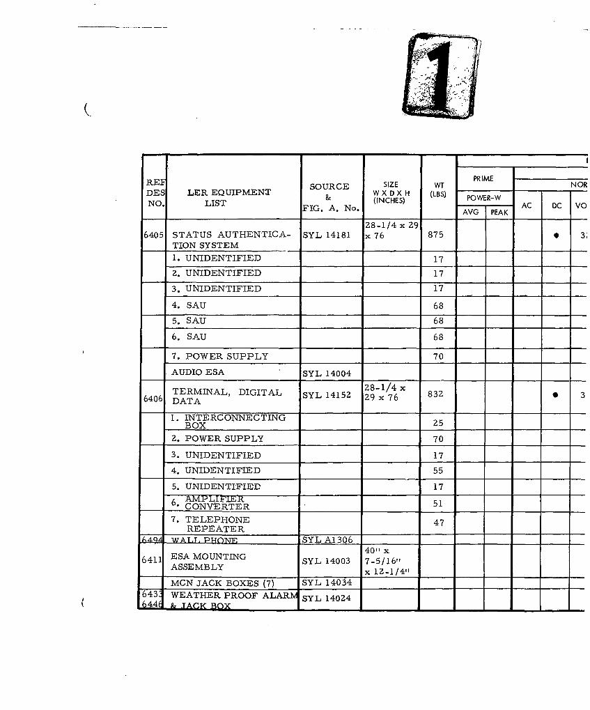
REF SOURCE SIZE W PRIME NORDES LER EQUIPMENT & WXINH POWER-W
NO IT&(INCHES) PWR AC DC VONO. LIST FIG. A. No. AVG PEAK
28-1/4 x 29
6405 STATUS AUTHENTICA- SYL 14181 x 76 875 3;TION SYSTEM
1. UNIDENTIFIED 172. UNIDENTIFIED 17
3. UNIDENTIFIED 17
4. SAU 68
5. SAU 68
6. SAU 68
7. POWER SUPPLY 70
AUDIO ESA SYL 14004
TERMINAL, DIGITAL SYL 14152 289/ x 830 36406 DATA
1. INTERCONNECTINGBOX 25
2. POWER SUPPLY 70
3. UNIDENTIFIED 17 J
4. UNIDENTIFIED 55
5. UNIDENTIFIED 176. AAMPIEER 5, 6CONVERTER 517. TELEPHONE 47
REPEATER
L,49 WATTP-ON1E SYL A1306 40"_x
6411 ESA MOUNTING SYL 14003 7-5/16"
ASSEMBLY x 12-1/4"14003 7-5
MCN JACK BOXES (7) SYL 14034
1643 WEATHER PROOF ALARM SYL 14024-44( 1 & .TACK BOX _ __ _.
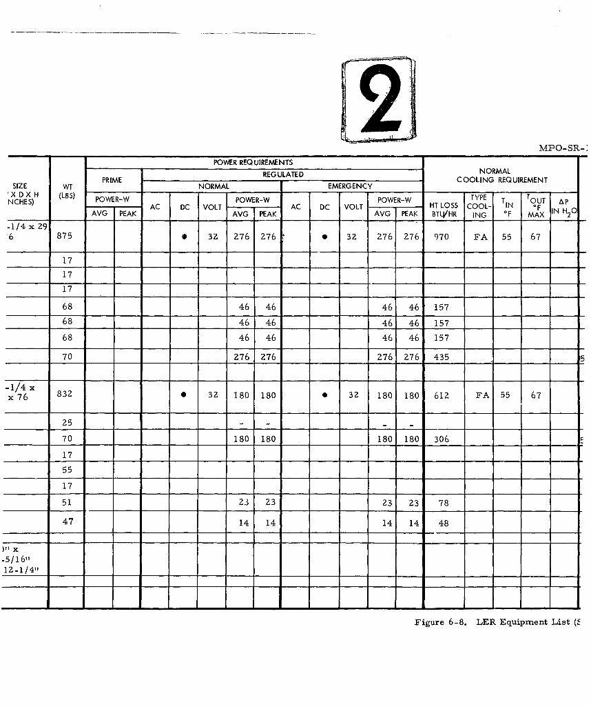
MPO-SR-:
POWER REQUIREMENTSREGULATED NORMALREGUATE COOLING REQUIREMENT
SIZE WT NORMAL EMERGENCY'X DX H (LBS) TYPE TNCHES) POWER-W POWER-W POWER-W T TOUT &p
AC DC VOLT AC DC VOLT HT LOSS COOL- IN OF IN H 0AVG PEAK AVG PEAK AVG PEAK BTU/HR ING OF MAX 2
-1/4 x Z9'6 875 * 3Z 276 276 0 3Z 276 276 970 FA 55 67
17
17
17
68 46 46 46 46 15768 46 46 46 46 157
68 46 46 46 46 157
70 276 276 276 276 435 5
-1/4 xx 76 832 0 3Z 180 180 0 32 180 180 612 FA 55 67
25 -__ _ _ _ __ _ _ _ -__ __ _
70 180 180 180 180 306
17
55
17
51 23 23 23 Z3 78
47 14 14 14 14 48
)f X
-5/16"1Z-1/4"f
Figure 6-8. LER Equipment List ("
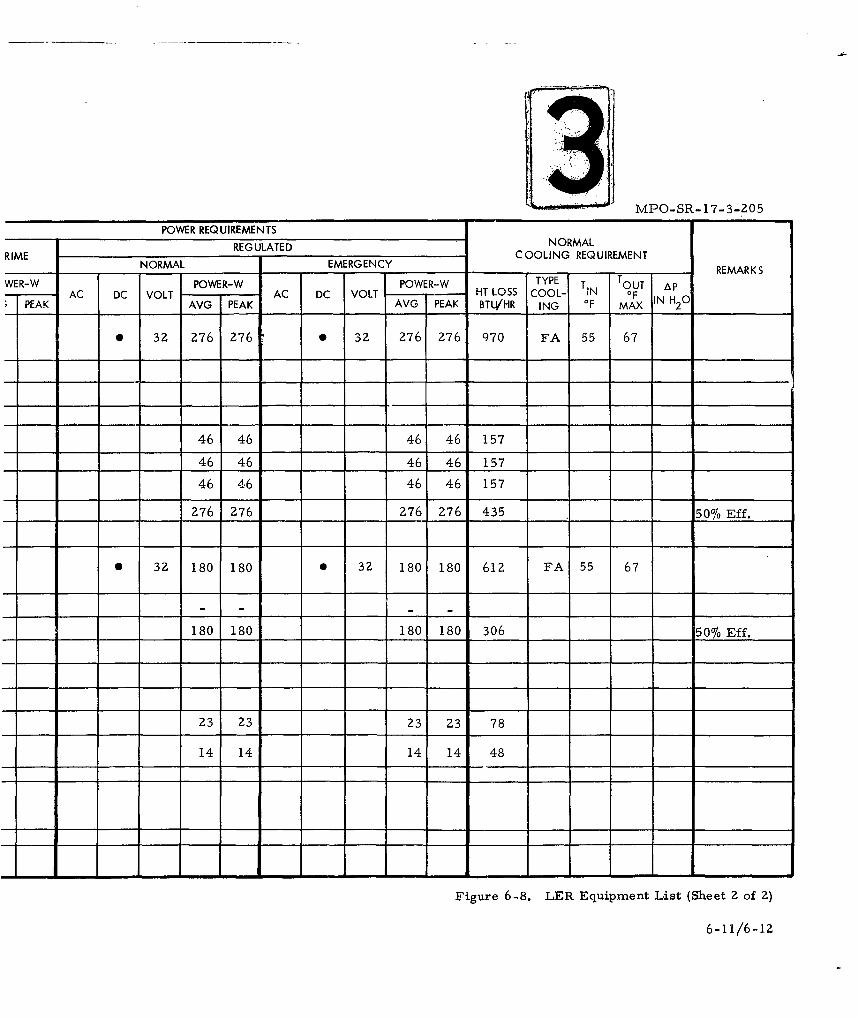
AC DC VOLT A DC VOLT -3POWER REQUIREMENTS
REGULATED NORMALRIME NOMLEEG N YCOOLING REQUIREMENTRE AKWER-W POWER-W POWER-W TYPE T T OTAPEKAGPEAK AVG PEAK BTLVHR ING 0FMAX IH 2 0______
* 3Z 276 276 * 3Z 276 276 9 70 FA 55 67
46 46 46 46 157
46 46 46 46 157 ______
46 46 46 46 157
___276 276 276 276, 435 1__ __ 5076 Eff.
* 32 180 180 0 32 180 180 612 FA 55 67
___180 180 1801 180 306 ___ 50% Eff.
23 23 23 23 78
14 14 14 14 48
T-i - - - I - - - - - - - I-
Figure 6-8. LER Equipment List (Sheet 2 of 2)
6-11/6-12
MPO-SR-i 7-3-205
& The Sylvania GES equipment is mounted in standard Minuteman
Equipment Racks for which a bolt-down pattern is shown in ICD. Draw-
ing No. 25-33ZZ6, entitled GES Equipment LF and LCC Installation
Envelope and Cooling.
6.4 MECHANICAL
Cooling requirements for Sylvania GES racks are delineated in
Figure 6-8, the Sylvania Equipment List applicable to the LER. Cool-
ing shall be provided by others in consonance with BSD Exhibit 62-80.
6.5 ELECTRICAL
Power required for Sylvania GES equipment to be located within
the LER is delineated on the Sylvania Equipment List (Figure 6-8). All of
this equipment must remain operative during pre- and post-attack periods.
Power supplied by others shall conform to BSD Exhibits 62-4 and 6Z-77.
Two conduits, each five inches inside diameter, for voice and data
communication cable shall be provided by others from the LER EMP En-
closure to a point Z5 feet outside the fence surrounding the LF (see Figure
6-9). This conduit shall provide protection for the cable to survive wea-
pons effects. The position of the conduit end shall be marked by a stake
to facilitate locating when the cable is placed. The end of the conduit
shall be suitably plugged for protection during the construction phase.
The minimum conduit bend radius shall be 36 times the diameter of the
installed conduit. The cable to be placed in this conduit will be provided
by Sylvania. The conduit utilization outlined above is for one active and
one spare duct. A pull wire will be left in each conduit when the conduit
is placed. Depth of bury at field end where staked shall be four feet.
At all LER's a single one-inch conduit shall be provided by
others from the LER to the adjacent LEB for passage of the plastic
pressurizing line from the compressor located in the LEB. The size
of the cable pressurizing line is determined to be 1/4-inch I. D. Its
conduit bend radius is considered non-critical. Sylvania will select
6-13
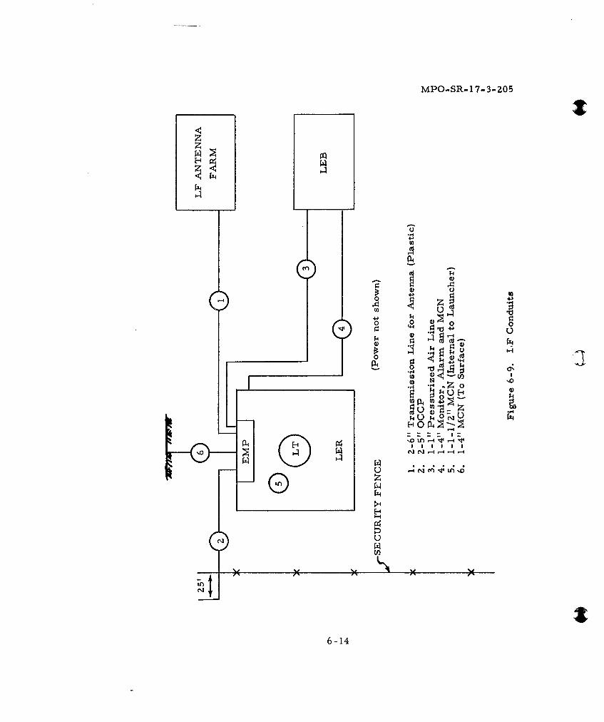
MPO..SR-17-3-205
A 4
4J J
0) 0
44 0 0
44-
p. 4 4
L_ _ _ _
0 N1
U.4 U4 I - 1
-
6-144
MPO-SR-17-3-Z05
specific LEB's from this general arrangement in which to house com-
pressor-dryers. This conduit shall terminate within the EMP enclosure.
A pull wire will be left in this conduit when the conduit is placed.
A single 4-inch hardened conduit shall be provided by others from
the LEB to the LER for the passage of the MCN cable and the pressuriza-
tion monitor and alarm cable. (The size of the monitoring signal cable
will be determined by Sylvania.) Its bend radius is considered non-critical.
A pull wire will be left in this conduit when the conduit is placed. This
conduit shall not enter the EMP Enclosure of the LER, but shall terminate
along the east end wall of the EMP enclosure. See Figure 6-13.
Two 6-inch plastic conduit shall be provided by others from the
LER to the adjacent LF antenna area for passage of the Sylvania antenna
feed cables. This conduit is required to be a straight-line routing device
and shall enter the EMP enclosure at a height of six and one-half feet
above the floor in that area. A pull wire shall be left in these conduit
when the conduit is placed. Lateral displacement shall be two feet east
of the south end wall of the EMP enclosure (see Figure 6-Z).
A telephone conduit network for MCN shall be provided by others.
It shall consist of the following:
(1) one 4-inch conduit from the EMP room to the surface forweather proof jack box and alarm set, which shall be mountedon left-hand wing wall of closure structure.
(2) one and one-half inch conduit around the launch tube servingseven jack boxes, with conduit stopping one foot each side ofjack boxes. Jack box mounting heights shall be 42 to 48inches above floors.
(3) access box at base of launch tube to accept jack box locatednear sump pump.
See supplementary sketches elsewhere in this section for additional
conduit information.
6-15
MPO-SR-17-3-Z05
All above noted conduits shall be provided by others as specified
by Sylvania.
Cable trays in the vicinity of Sylvania GES racks within the LER
shall be provided by others to satisfy an intra-rack cabling configuration
to be determined by Sylvania.
6.6 COMMUNICATIONS
Telephone jacks will be provided by Sylvania in the LER to permit
voice communications for the MCN. The LER is normally not manned.
Maintenance personnel will carry plug-equipped head-set telephones.
6.7 INTERFACES
The following interfaces are recognized in conjunction with Sylvania
GES in the LER.
6. 7. 1 Architectural - Minimum space requirements must be provided for
equipment as shown on the Sylvania Equipment List (Figure 6-8) and as
specified elsewhere by Sylvania.
6. 7. 2 Structural - The weight of Sylvania GES modules is shown on the Syl-
vania Equipment List (Figure 6-8). Sylvania equipment to be placed within
the LER shall be securely fastened by others in accordance with Sylvania foot-
ing detail, and mounting plates suitable to withstand weapons effects.
6. 7. 3 Mechanical - A round flexible duct, damper and holding clamp,
provided by others, capable of withstanding weapons effects, shall inter-
face with the inlet transition duct, Boeing number BACD40F3, which is a
part of BACC60BO3C1FOZ (Minuteman Rack) provided by Sylvania. See the
Sylvania equipment layout drawing, Figure 6-1, for guidance as to locations
of units of equipment. Inlet transition duct is shown on ICD No. 28-38226.
6. 7. 4 Electrical - Electrical service connections to GES equipment within
the LER shall be provided by others, as specified by Sylvania. Grounding
of GES shall be provided by others in accordance with BSD Exhibit 62-75
and as otherwise specified in Figure 6-15. Provisions for the installation
6-16
C MPO-SR-17-3-Z05
of three ESA Mounting Assemblies shall be made at the cable entrance of
the launch tube. Mounting details will be identical with those at the LCGC.
For further details relative to mounting of ESA devices, see Figures 2-19
and 2-20a, b, and c, in Section 2 of this document.
6. 7. 5 Communications - Telephone jack boxes and alarm devices will
be supplied by Sylvania for installation by others. Locations within the
LER are as shown on Sylvania drawings in this section. Weather proof
jack box and alarm shall be mounted on left-hand wing wall at closure
structure.
6. 7. 6 Antenna Farm - Interfaces at the LF antenna farm pertaining to
the conduit requirements at the Sylvania MF antenna are detailed in Sec-
tion 8, Antenna Farms, of this document.
6-17
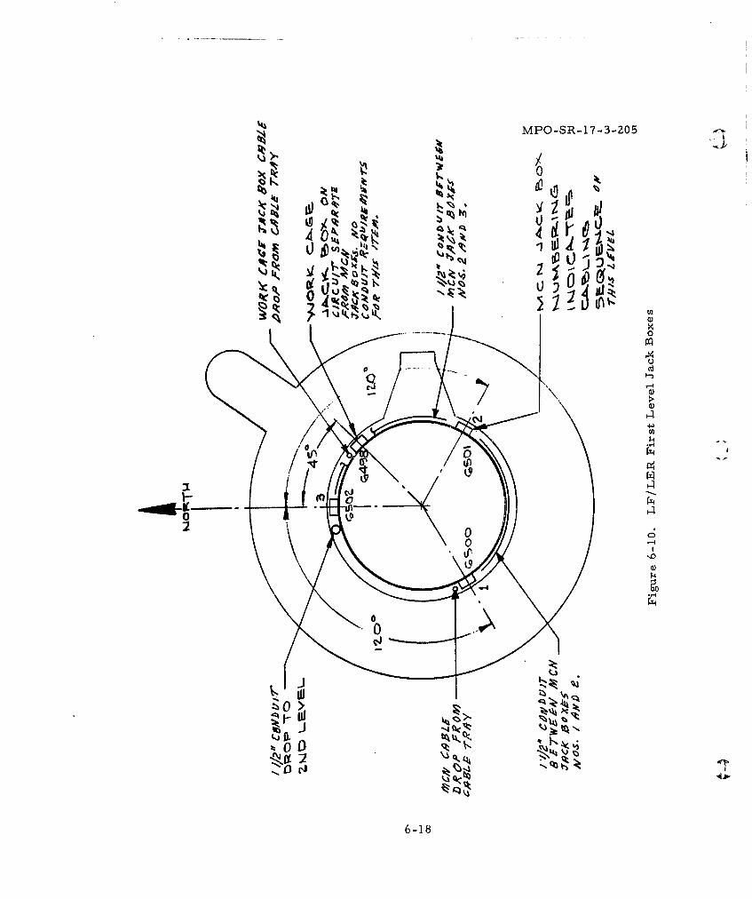
MPO-SR-1 7-3-205
4O4
00
4J
6-184
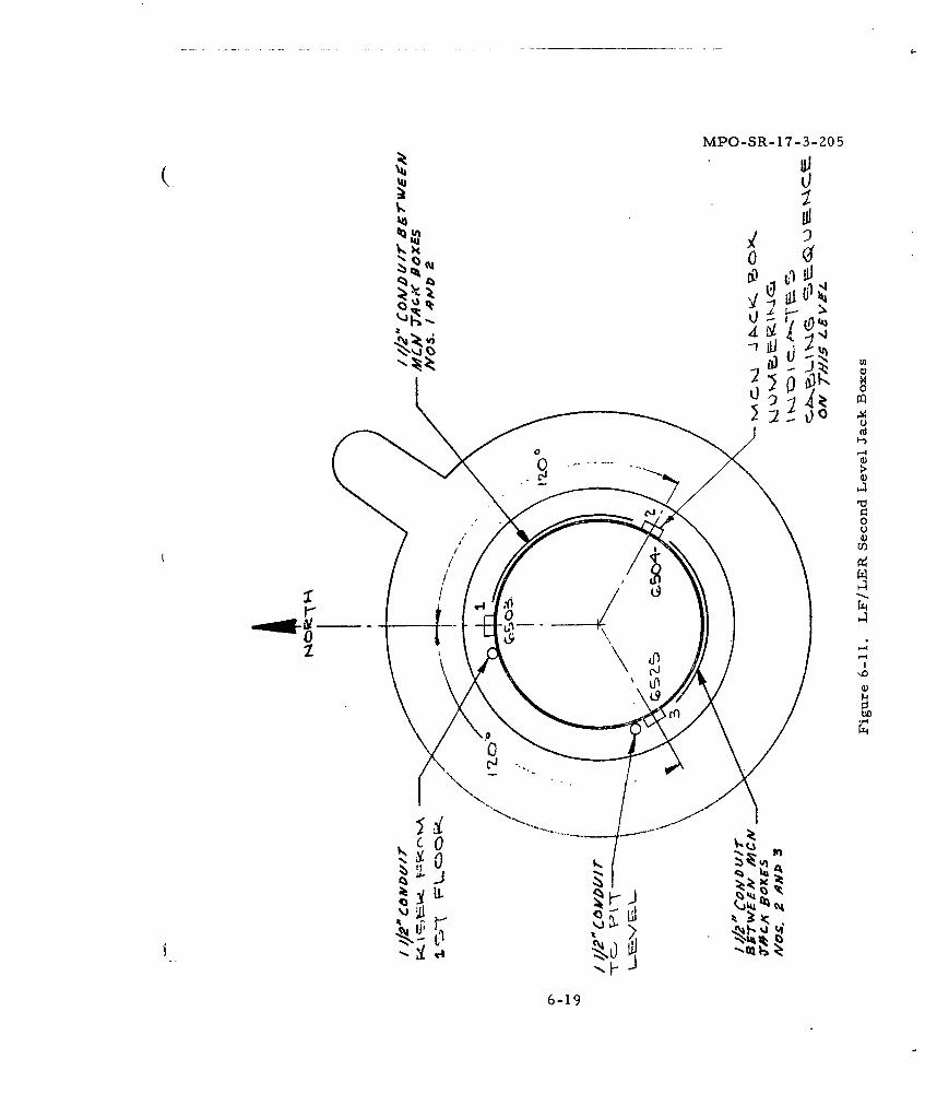
MPO-SR-17-3-ZO5
f l40
Vi 0J'HI
V)
00
UlU
Sk'0
IL
6-19
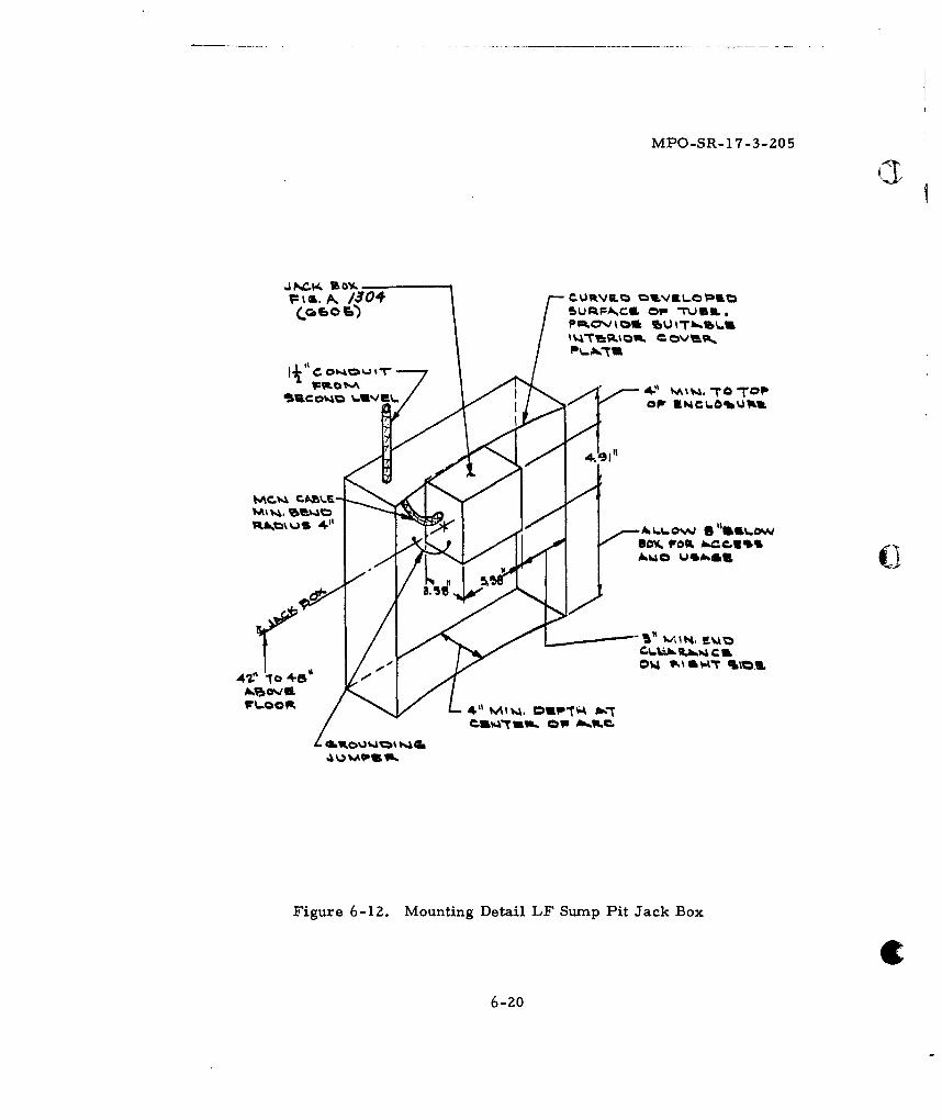
MPO-SR-17-3-205
WF.. A, /304 CJV. '3OS
If C. *-6. OP J
WR~A .~' .A~~4.91O
am% Paro. hbCCUI%
Figre6-1. outin Dtal L SpPitJak ox
zmC6-20A I
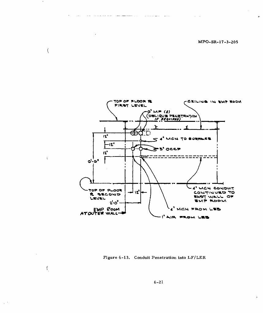
MPO-SR-17-3-205
Top Opr ptL.opt Va ZCKI%.I'.& % l~l ROOM
GOM IIU IMKRW
COls 1.
4 W~ov \-O'
ArTOv1-O WALL--W
Figure 6-13. Conduit Penetration into LF/LER
6-21
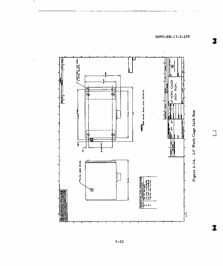
MPO-SR-17-3-Z05
B LO
S 0 0
dC
00
6-22
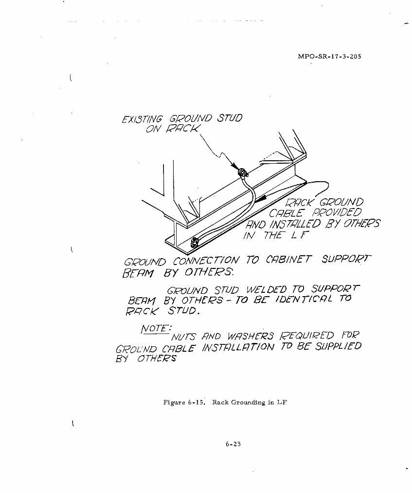
MPO-SR- 17-3-205
ECx/&//VG' 61POIMD Sr/I0
/AMDf //AL FD /6Ft
6~&O1IA'D1VC7/O1VM Ro CF6/tF SLIPPOPT~ fHy OTA/EPS
6-FW/ND 37-/D W-L Df-) T-0 31/PPOPR78U-,q'1 By 0 THCPS - FO 2C- /1DN 7F/OAt 7-0
P/A7c$ SrVtD.
I/T7 RAID WPSgfi)? YCE FLI/IPED FOP6Y~OJMD p/L f- /A1,SPL L P770/V FO~ 85 SL/PPLf lD
Figure 6-15. Rack Grounding in LF
6-23
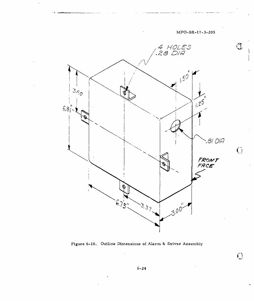
MPO-SR-17-3-205
81%/
Figure 6-16. Outline Dimensions of Alarm & Driver Assembly
6-24
MPO-SR-17-3- 205
SECTION 7
LAUNCHER EQUIPMENT BUILDING (LEB)
7.1 FUNCTION
The LEB shall be the center for all air breathing apparatus that
supports the associated launcher. Within this structure, Sylvania re-
quires a space allocation for the placement of a cable pressurization
system and communications jack box and alarm.
7. 2 ARCHITECTURAL
Space availability and access shall be provided within all LEB's
for placement, at a location to be determined later, of pressurization
equipment of the size and weight shown on the applicable Sylvania
Equipment List (Figure 7-1). Preference for the location of the com-
pressor-dehydrator within an LEB is not an architectural constraint,
except that access to the entire cabinet shall be provided for mainten-
ance purposes. It is further required that an additional clear space of
four inches at sides and rear be provided for air circulation and bracket
attachment.
A refrigerant-type, dryer-compressor is contemplated for this
installation. There is no requirement for a drain to remove the water
condensed from the intake air since this is accomplished by re-evapora-
tion into the room.
Routine maintenance imposes a cabinet accessibility requirement
to accomplish such tasks as lubrication, belt adjustments, cleaning or
changing strainers and filters, and replacing chemical canisters.
7.3 STRUCTURAL
Provision shall be made by others for secure fastening of the
pressurization system within the LEB. The equipment is designed to
( be fastened to the wall, and is provided complete with detachable brack-
ets which bolt to the cabinet. The method of securing these brackets to
7-1
MPO-SR-17-3-205 Jthis equipment room structure shall be provided by others. For dimen-
sional drawing of the placement of wall mounting brackets for the
compressor-dryer, refer to ICD 25-38272. A mounting panel shall be
provided by others for the placement of the pressurization system and
for the MCN jack box and alarm set, for installation by others. Jack
box mounting height centerline shall be approximately 5 feet above the
work platform. See Sylvania supplementary illustrations for fastening
pattern of jack box and alarm set.
7.4 MECHANICAL
Sylvania will furnish a cable pressurization system complete with
self-contained compressor, receivers, distribution manifold and primary
control devices for installation of the selected LEB. The assembly shall
have characteristics as defined on the Sylvania Equipment List (Figure
7-1). Between the LEB and the LER a plastic pressure line and con-
necting clamps will be provided by Sylvania for installation by others.
7.5 ELECTRICAL
The compressor-dehydrator requires power as defined in the
Sylvania Equipment List. Normally regulated commercial power will
meet the requirements for this device. This equipment operates con-
tinuously; however there is no requirement to operate it during battery
mode.
At each LEB a four-inch conduit shall be provided to carry a
cable containing the MCN circuits and monitor alarm pairs to the adja-
cent LER as stated in Section 6. In addition to this specified conduit, a
one-inch conduit shall be provided at all LEB's to carry the pressure line
from the compressor-dehydrator to the pressurized communications cable
in the adjacent LER. Pressurization of the Minuteman hardened cable
is accomplished by a connection of the air line within the adjacent LER.
Actual utilization of the pressurization line conduit will occur only at
selected LER's dependent upon actual field conditions governing place-
ment of cable and lengths of cable runs. Monitoring circuits located
at the compressor-dryer device are high pressure, low pressure and
high humidity sensors.
7-2
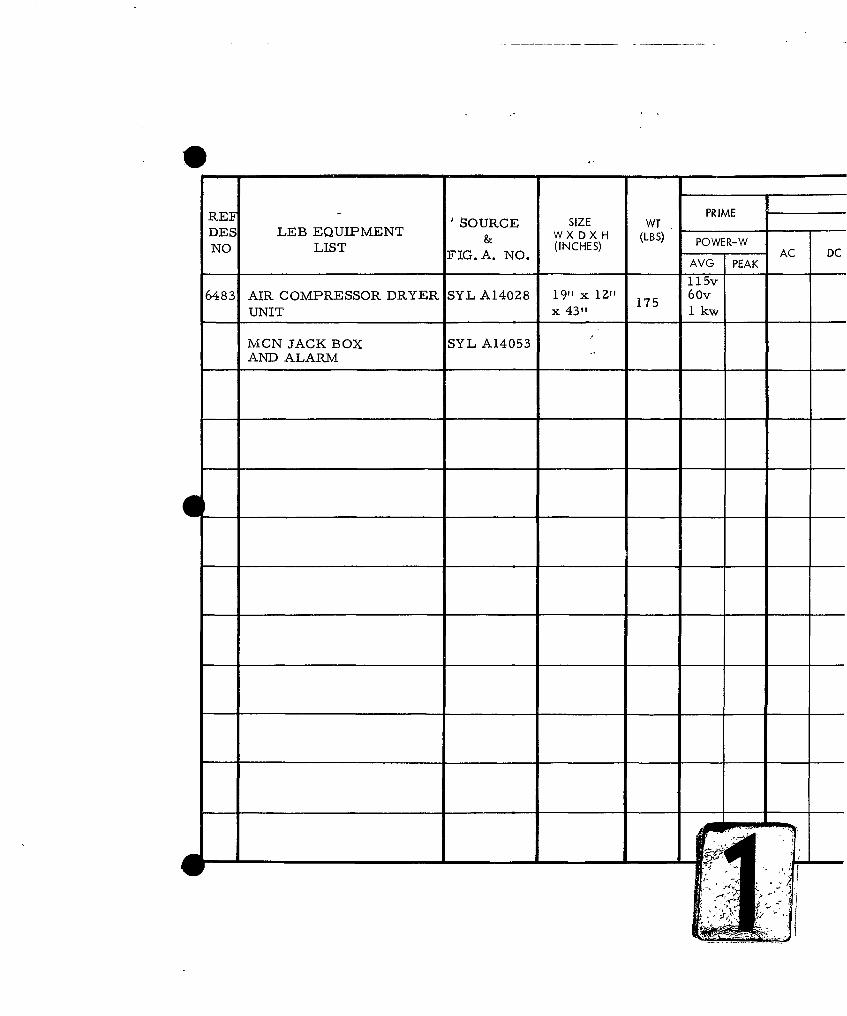
REFO8URCE SIZE WT PRIME_ __
DES LEB EQUIPMENT & W X D X H (LBS) POWER-WNO LIST FIG. A. NO. (INCHES) AC DC
AVG7PEAK
1 15v6483 AIR COMPRESSOR DRYER SYL A14028 19"1 x 12"117 6 0v
UNIT x 43"t 17 I kw
MCN JACK BOX SYL A14053AND ALARM
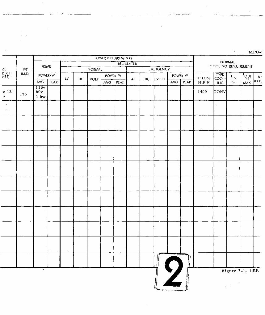
MPO-1
POWER REQUIREMENTS
REG ULATE D NORMALPRIME COOLING REQUIREMENTLE WT _____ ___ NORMAL EMERGENCY __ ____
DJ X H (LBS) PWRWPWR OW- TYPETHES) TYPE POTOUT ApAC DC VOLT AC DC VOLT HT LOSS COOL- IN OF
AVG PEAK AVG PEAK AVG PEAK BTLVHR ING F MAX H,
1 1Svx 1Z" 175 6 0v 3400 CONV" I kw
Figure 7-1. LEB
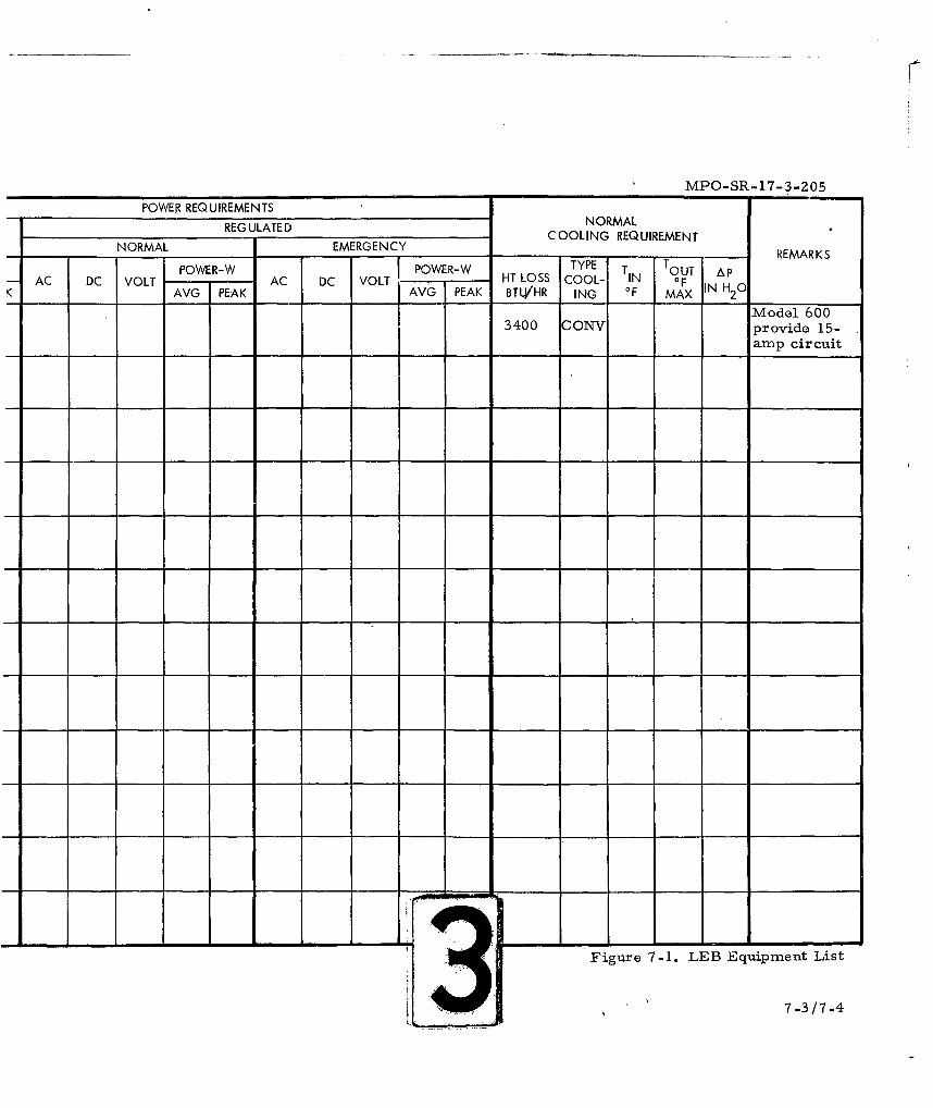
MPO-SR-17-3-Z05
POWER REQUIREMENTSREGUATEDNORMAL
REG ULATED COOLING REQUIREMENT
NORMAL EMERGENCY REMARKS
ACPOWER-W POWER-W HT LOSS COOL- TIN OF 0PK AVG PEAK AVG PEAK BTL/HR ING OF MAX IN H2 0
Model 6003400 CONV provide 15-
amp circuit
Figure 7-1. LEB Equipment List
7-3/7-4
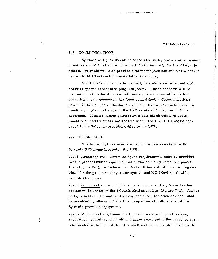
MPO-SR- 17-3-205
7.6 COMMUNICATIONS
Sylvania will provide cables associated with pressurization system
monitors and MCN circuits from the LEB to the LER, for installation by
others. Sylvania will also provide a telephone jack box and alarm set for
use in the MCN network for installation by others.
The LEB is not normally manned. Maintenance personnel will
carry telephone headsets to plug into jacks. (These headsets will be
compatible with a hard hat and will not require the use of hands for
operation once a connection has been established. ) Communications
pairs will be carried in the same conduit as the pressurization system
monitor and alarm circuits to the LER as stated in Section 6 of this
document. Monitor-alarm pairs from status check points of equip-
ments provided by others and located within the LEB shall not be con-
veyed in the Sylvania-provided cables to the LER.
7.7 INTERFACES
The following interfaces are recognized as associated with
Sylvania GES items located in the LEB.
7. 7. 1 Architectural - Minimum space requirements must be provided
for the pressurization equipment as shown on the Sylvania Equipment
List (Figure 7-1). Attachment to the facilities wall of the mounting de-
vices for the pressure dehydrator system and MCN devices shall be
provided by others.
7.7. 2 Structural - The weight and package size of the pressurization
equipment is shown on the Sylvania Equipment List (Figure 7-1). Anchor
bolts, vibration elimination devices, and shock isolation devices, shall
be provided by others and shall be compatible with dimension of the
Sylvania-provided equipment.
7. 7. 3 Mechanical - Sylvania shall provide as a package all valves,
regulators, switches, manifold and gages pertinent to the pressure sys-
tem located within the LEB. This shall include a flexible non-metallic
7-5
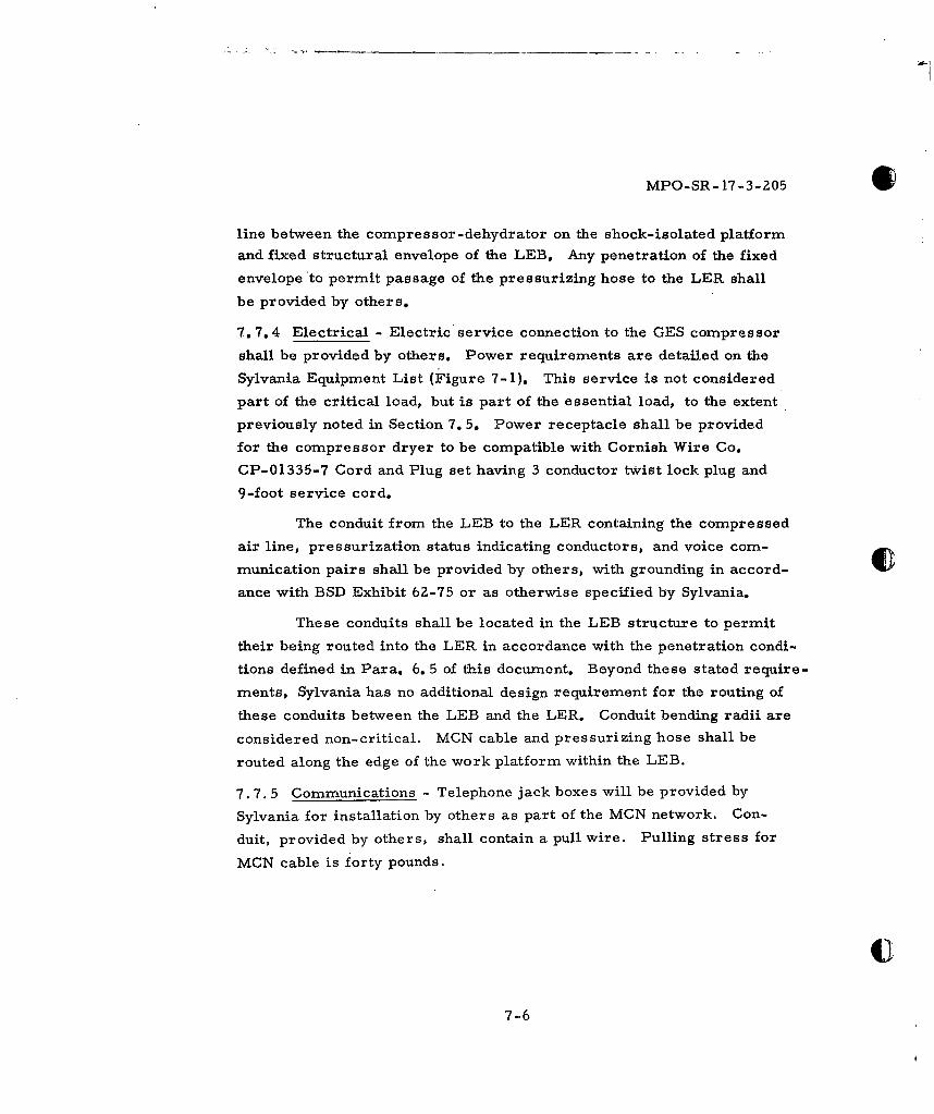
MPO-SR-17-3-205
line between the compressor-dehydrator on the shock-isolated platform
and fixed structural envelope of the LEB. Any penetration of the fixed
envelope to permit passage of the pressurizing hose to the LER shall
be provided by others.
7. 7.4 Electrical - Electric service connection to the GES compressor
shall be provided by others. Power requirements are detailed on the
Sylvania Equipment List (Figure 7-1). This service is not considered
part of the critical load, but is part of the essential load, to the extent
previously noted in Section 7. 5. Power receptacle shall be provided
for the compressor dryer to be compatible with Cornish Wire Co.
CP-01335-7 Cord and Plug set having 3 conductor twist lock plug and
9-foot service cord.
The conduit from the LEB to the LER containing the compressed
air line, pressurization status indicating conductors, and voice com-
munication pairs shall be provided by others, with grounding in accord-
ance with BSD Exhibit 62-75 or as otherwise specified by Sylvania.
These conduits shall be located in the LEB structure to permit
their being routed into the LER in accordance with the penetration condi-
tions defined in Para. 6. 5 of this document. Beyond these stated require-
ments, Sylvania has no additional design requirement for the routing of
these conduits between the LEB and the LER. Conduit bending radii are
considered non-critical. MCN cable and pressurizing hose shall be
routed along the edge of the work platform within the LEB.
7.7. 5 Communications - Telephone jack boxes will be provided by
Sylvania for installation by others as part of the MCN network. Con-
duit, provided by others, shall contain a pull wire. Pulling stress for
MCN cable is forty pounds.
77-6
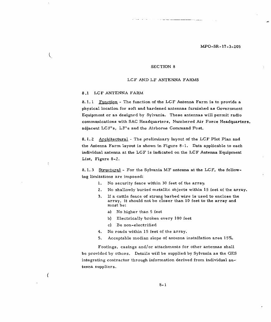
MPO-SR- 17-3-205
SECTION 8
LCF AND LF ANTENNA FARMS
8.1 LCF ANTENNA FARM
8. 1. 1 Function - The function of the LCF Antenna Farm is to provide a
physical location for soft and hardened antennas furnished as Government
Equipment or as designed by Sylvania. These antennas will permit radio
communications with SAC Headquarters, Numbered Air Force Headquarters,
adjacent LCF's, LF's and the Airborne Command Post.
8. 1. 2 Architectural - The preliminary layout of the LCF Plot Plan and
the Antenna Farm layout is shown in Figure 8-1. Data applicable to each
individual antenna at the LCF is indicated on the LCF Antenna Equipment
List, Figure 8-Z.
8. 1. 3 Structural - For the Sylvania MF antenna at the LOF, the follow-
ing limitations are imposed:
1. No security fence within 30 feet of the array.
2. No shallowly buried metallic objects within 15 feet of the array.
3. If a cattle fence of strung barbed wire is used to enclose thearray, it should not be closer than 10 feet to the array andmust be:
a) No higher than 5 feet
b) Electrically broken every 100 feet
c) Be non-electrified
4. No roads within 15 feet of the array.
5. Acceptable median slope of antenna installation area 15%.
Footings, casings and/or attachments for other antennas shall
be provided by others. Details will be supplied by Sylvania as the GES
integrating contractor through information derived from individual an-
tenna suppliers.
8-1
MPO-SR- 17-3-2058.1. 4 Mechanical - Not applicable.
8. 1. 5 Electrical - Conduits to the LCF Antenna Farm are delineated
in Section 2. The four 6-inch conduit for the Sylvania MF Antenna shall
be installed by others. They shall be capped and staked for identification,
5 feet outside of the established fence perimeter of the antenna location
and 8 feet below the finished grade line. These conduit shall provide a
straight-line entry at the MF Antenna lead into the LCC EMP enclosure.
All other antenna conduit shall terminate at the antenna locations at 4 feet
below grade.
8. 1. 6 Communications - Communications for the Antenna. Farm will be
above ground and provided as part of the MCN from the LCSB by use of a
headset and a long cable.
8. 1. 7 Interfaces - Within the LCF Antenna Farm, interfaces between
Sylvania and others are as follows:
8. 1. 7.1 Architectural - Figures 8-1 and 2-21 are the LCF Plot Plan
and the LCF Antenna Farm conduit layout, respectively. Until the layout
is final, fence locations, drainage provisions, parking areas and roadways
cannot be fully defined.
8. 1. 7. 2 Structural - Drawings will be supplied by Sylvania showing
structural interfaces.
8. 1. 7. 3. Mechanical - Not applicable.
8. 1. 7. 4 Electrical - Each antenna in the LCF Antenna Farm w.il re-
quire hardened conduit for its transmission and control lines. These
conduits are depicted in Figure Z-21, Section 2.
8. 1. 7.5 Communications - Not applicable.
8-2
MPO-SR- 17-3-2058.2 LF ANTENNA FARM
8. 2. 1 Function - The function of the LF Antenna Farm is to provide a
physical location for the Sylvania MF antenna.
8. 2. 2 Architectural - The preliminary layout of the Sylvania antenna at
the LF is shown in Figure 8-3. Physical size of the antenna is as shown
on the LF Antenna Farm Equipment List, Figure 8-4.
8. 2. 3 Structural -
1. No security fence within 30 feet of the array.
2. No shallowly buried metallic objects within 15 feet of the array.
3. If a cattle fence of strung barbed wire is used to enclose thearray, it should not be closer than 10 feet to the array andmust be:
a) No higher than 5 feet
b) Electrically broken every 100 feet
c) Be non-electrified.
4. No roads within 15 feet of the array.
5. Acceptable median slope of antenna installation area 15%.
8. Z. 4 Mechanical - Not applicable.
8. 2. 5 Electrical - The conduit to the Sylvania MF antenna shall be two
6-inch I. D. plastic, installed by others. They shall be capped and staked
for identification, terminating 5 feet outside the established fence perim-
eter of the antenna location and 8 feet below the finished grade line at its
outer extremity. These conduit shall provide a straight-line entry of the
MF antenna leads into the LF EMP enclosure.
8. 2. 6 Commun'.cations - Any communications necessary for maintenance
in the vicinity of the MF antenna will be provided by using the MCN jack
box (Sylvania Figure A14024) at ground level with Sylvania Figure A14035
headset.
8. 2. 7 Interfaces - Within the LF Antenna Farm, interfaces are as follows.
8-3
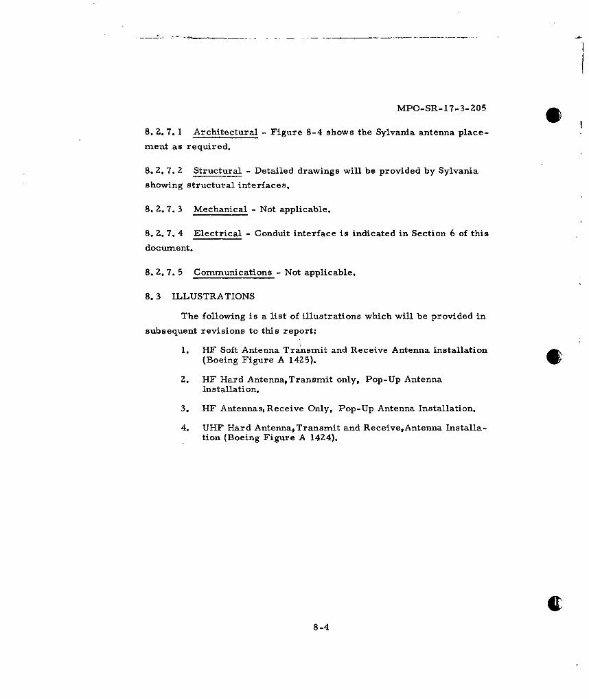
MPO-SR-17-3-Z05
8. 2. 7. 1 Architectural - Figure 8-4 shows the Sylvania antenna place-
ment as required.
8. 2. 7. Z Structural - Detailed drawings will be provided by Sylvania
showing structural interfaces.
8. 2. 7. 3 Mechanical - Not applicable.
8. 2. 7. 4 Electrical - Conduit interface is indicated in Section 6 of this
document.
8. Z. 7. 5 Communications - Not applicable.
8.3 ILLUSTRATIONS
The following is a list of illustrations which will be provided in
subsequent revisions to this report.
1. HF Soft Antenna Transmit and Receive Antenna Installation(Boeing Figure A 14Z5).
Z. HF Hard Antenna, Transmit only, Pop-Up AntennaInstallation.
3. HF Antennas, Receive Only, Pop-Up Antenna Installation.
4. UHF Hard Antenna, Transmit and Receive,Antenna Installa-tion (Boeing Figure A 14Z4).
8-4
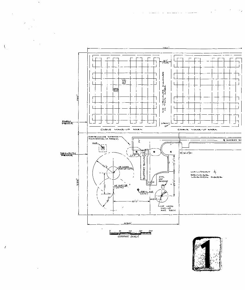
K I. ~7fTt
N"4iZ7
28ol
LA U
Gd1-Z01
h=C A-- ; J
~~~~~PPI S _____________ E
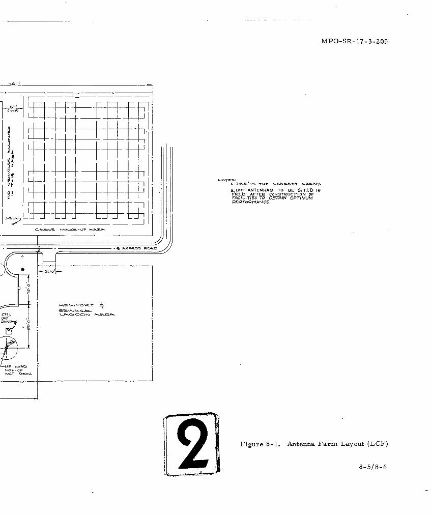
MPO-SR- 17-3-205
01 2.UH-F ANTENNAS TO BE SITED IWFIELD AFTER' CON.STR2UCtION OFFACIL TIE'S TO OBTAIN OPTIMUM
UlHF
'71VTER MAN C
A WFigure 8-1. Antena Farm Layout (LCF)
• 1 8-5/8-6
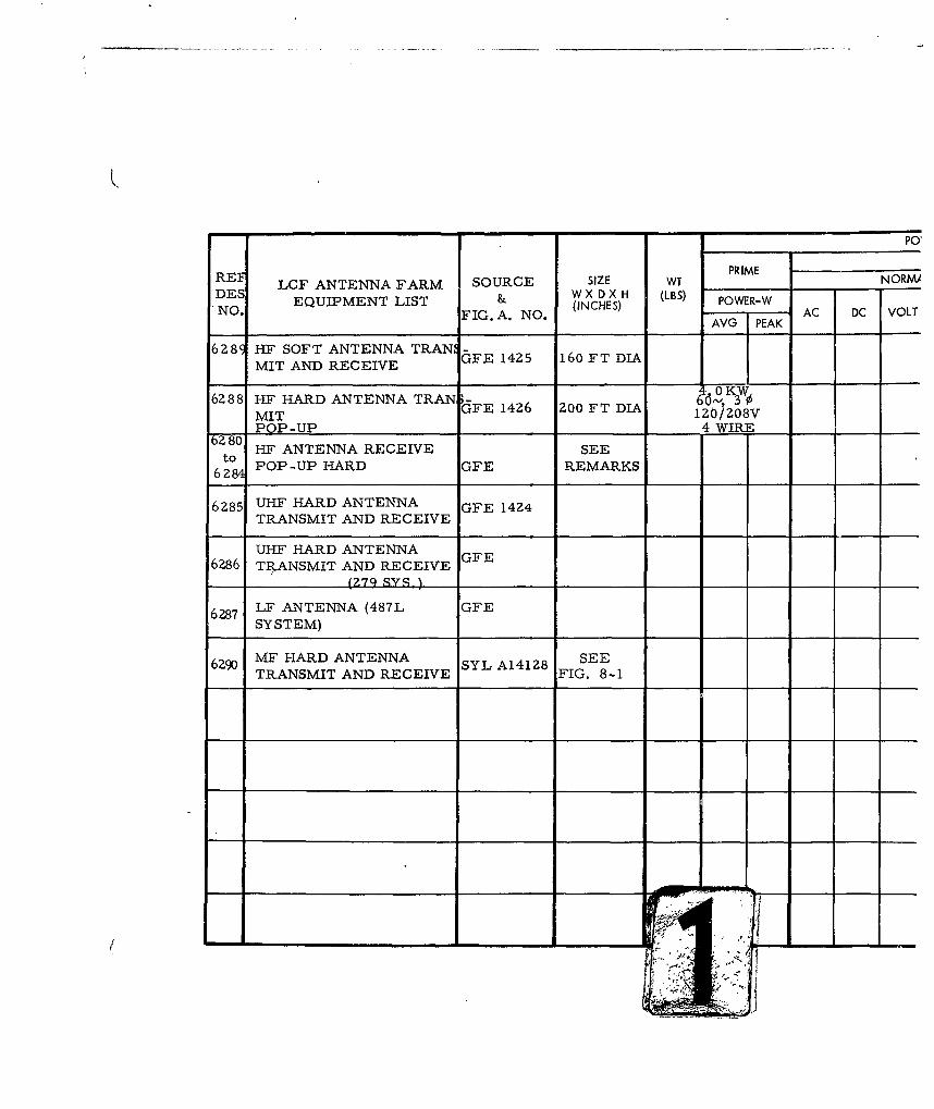
PO,
REF LCF ANTENNA FARM SOURCE SIZE WT PRIME NORMADES EQUIPMENT LIST & W X D X H (LBS) POWER-WNO, FIG. A. NO. (INCHES)AVG PEAKC DC VOLT
6289 HF SOFT ANTENNA TRAN -
MIT AND RECEIVE GFE 1425 160 FT DIA
0 OKW6288 HF HARD ANTENNA TRAN -FE 1426 200 FT DIA 66-, 30
MIT GZO/ZO8VPOP-UP 4 WIRE
to280 HF ANTENNA RECEIVE SEEto'
62 POP-UP HARD GFE REMARKS
6285 UHF HARD ANTENNA GFE 1424TRANSMIT AND RECEIVE
UHF HARD ANTENNA6286 TRANSMIT AND RECEIVE
(27q SYS I
6287 LF ANTENNA (487L GFESYSTEM)
6290 MF HARD ANTENNA SYL A14128 SEETRANSMIT AND RECEIVE FIG. 8-1
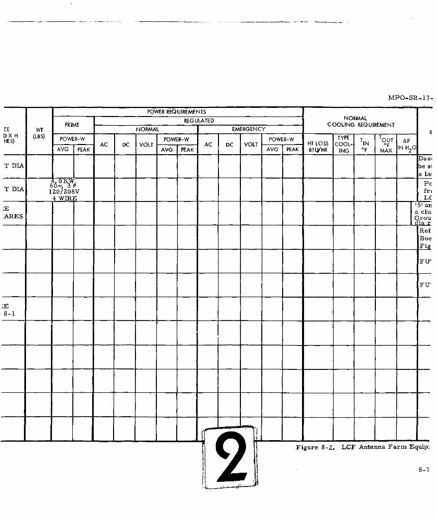
MPO-SR-17.
POWER REQUIREMENTS
REG ULATE D NORMALPRIME COOLING REQUIREMENTIE WT ____NORMAL____ - EMERGENCY___ - _R
D} X H (LBS) TYPE TOT PD HS) POWER-W POWER-W POWER-W TYPETT TAC DC VOLT AC DC VOLT HT LOSS COOL- IN OF
AVG IPEAK AVG PEAK AVG PEAK BT4/HR ING OF MAX IN H20Des4
T DIA b e S-L _ _ _ a lal
0OK-W PCT DIA 66-', 3T DIA IZ0/Z08V
4 WIRE _ _
51an
ARKS Groudi
RefBoe
F U'
F Ul
8-1
2 -- Figure 8-2. LCF Antenna Farm Equip:
8-8-7
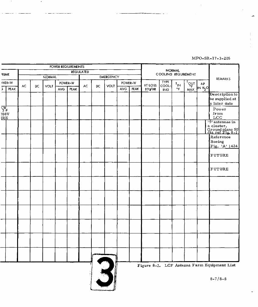
MPO-SR-17-3-205
POWER REQUIREMENTSREG ULATED NORMAL
'RIME REGMAL ULAY COOLING REQUIREMENTRMENORMAL, EME RG EN CY ______ ___ __- RE MAR KS
)WER-W POWER-W POWER-W TYPE T TOUT AP
- AC DC VOLT AC DC VOLT -- HT LOSS COOL- IN OF3 PEAK AVG PEAK AVG IPEAK BTU4/HR ING OF MAX N
Description to
be supplied at
a later date
Power
,08V from[RE LOG
' antennae ina cluster.
__ __ia ref Fiv 8 -1
ReferenceBoeing
_ ._ _ .Fig. 'A' 1424
FUTURE
FUTURE
Figure 8-2. LCF Antenna Farm Equipment List
8-7/8-8
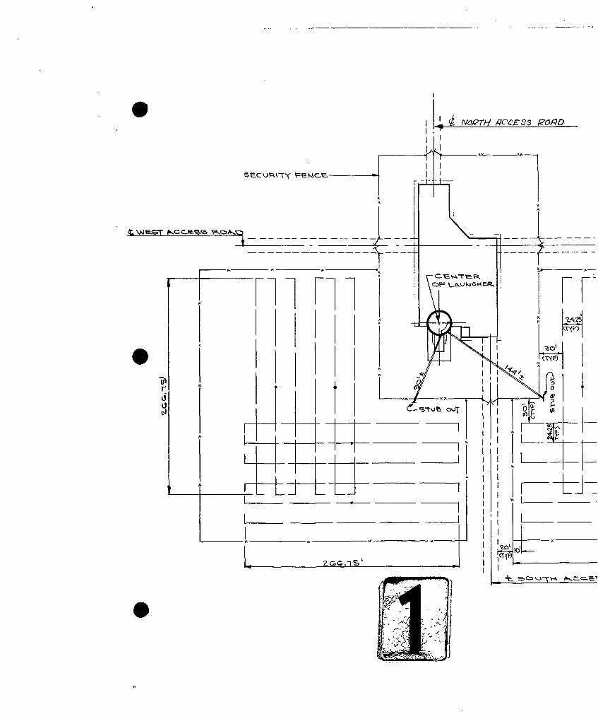
NVORTH qCCE3ss eOqo
S'300 Tjf
Iin
__ __ _ I __ _
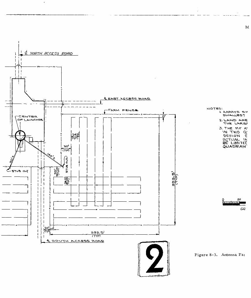
M
NVOPTH PCICESS POflo
qCTUL %N-
BE LI'AVTE:CI j QLADPAN'
0 . 0
o- I
O~S~ I J
_ _ I-FiurI-3 ntna a
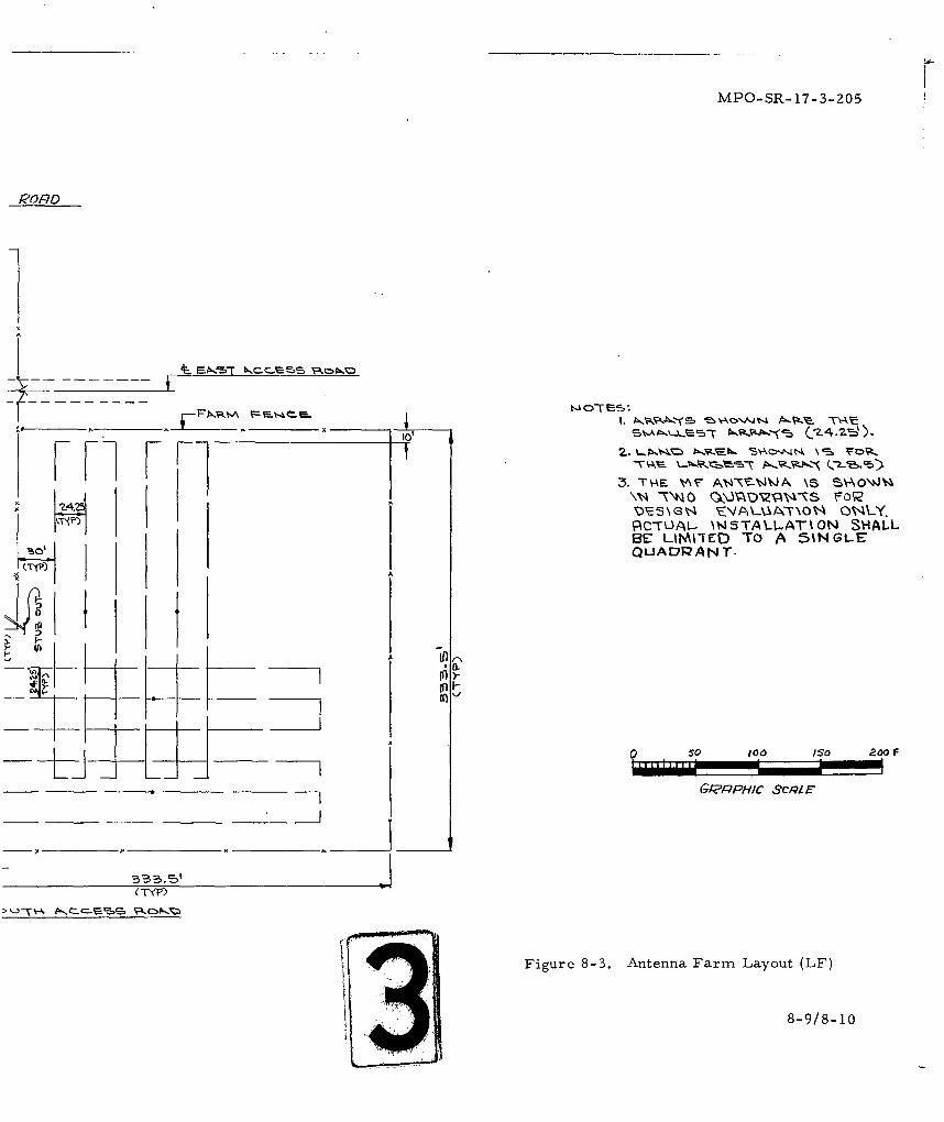
MPO-R-173-2r
PORDo
2-46 \N~ -TNO QOVADNNASS IF~
PC-TLAL- \WSTAV-.AT%0N SHALLBE LIMI-TED TO A :51NGLEQUADPAN T.
(TYPYPpco-"Q
Fiue83 nenaFr aot(F
8-9/8-1
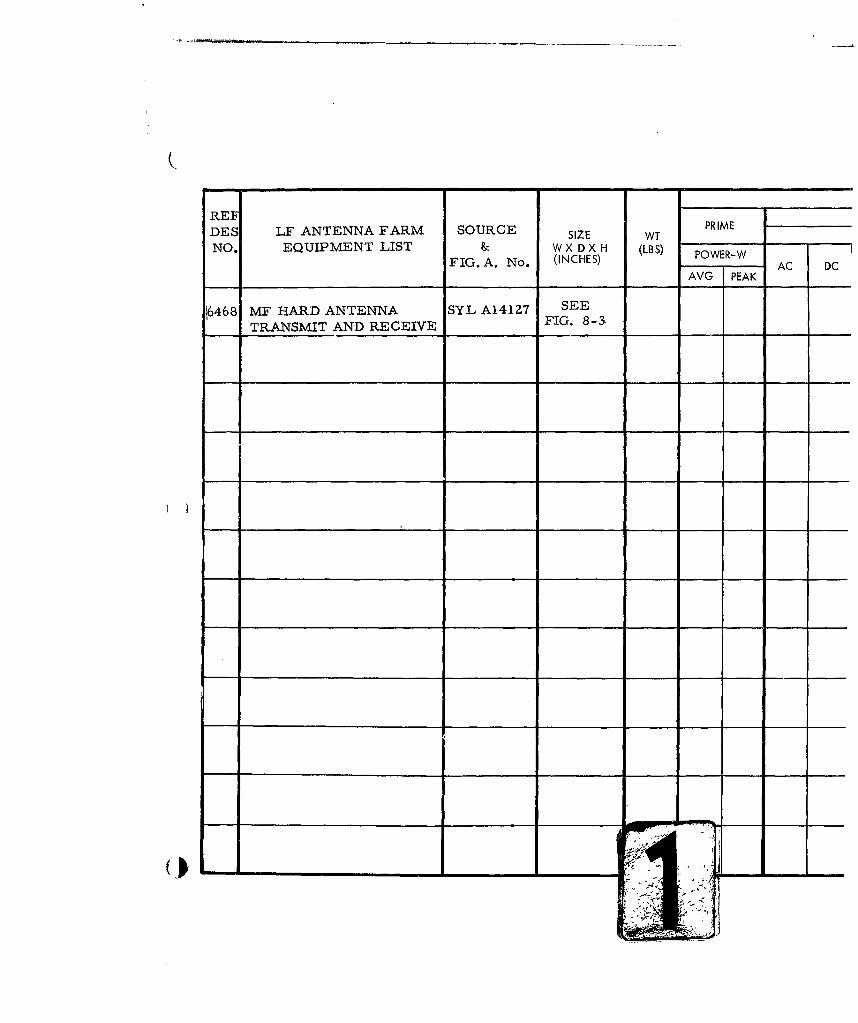
REFDES LF ANTENNA FARM SOURCE SIZE WT PRIME
NO. EQUIPMENT LIST & W X D X H (LBS) POWER-WFIG. A. No. (INCHES) AC DC
AVG PEAK
M6468 F HARD ANTENNA SYL A141Z7 SEE
TRANSMIT AND RECEIVE FIG. 8-3.
I-
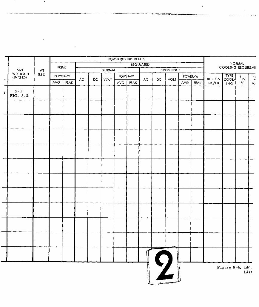
POWER'REQUIREMENTS
REG ULATE D NORMALPRIME I C OOLING REQUIREMESIZE WT NORMAL EMERGENCY C
W X D X H (LBS) OE-ERPR(INCHES) POWER-W POWER-W POWER-WT 0AC DC VOLT AC DC VOLT HT LOSS COOL- IN a
AVG PEAK AVG PEAK AVG PEAK BTU/HR ING "F M,
7 SEEFIG. 8-3
- -- - -.. - - - -- - -
Figure 8-4. LFList
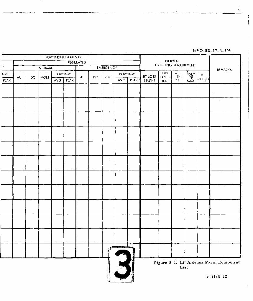
_'"PO-SR-17-3-205
POWER REQUIREMENTS
REGULATED NORMALCOOLING REQUIREMENT
NORMAL EMERGENCY REMARKS-WPOWER-W POWER-W TYPE T TOUT Ap
AC DC VOLT AC DC VOLT HT LOSS COOL- IN OF IN H 0PEAK AVG PEAK AVG PEAK BTL/HR ING OF MAX 2
Figure 8-4. LF Antenna Farm EquipmentList
8-11/8-12
MPO-SR- 17-3-205
SECTION 9
MISCELLANEOUS COVERAGE
9.1 GENERAL
This section will contain those miscellaneous details which are
not uniquely associated with any particular area or location. Such items
will include the weather-proof jack box and weather-proof alarm set, MCN
jack box, hands-free phone and wall mounted telephone.
(
9-1
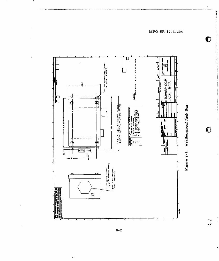
MPO-SR-17-3-205
S( 0
0. (0
ui
r Cdlove
P2 71
00
gqq4
fil Ii
9-2
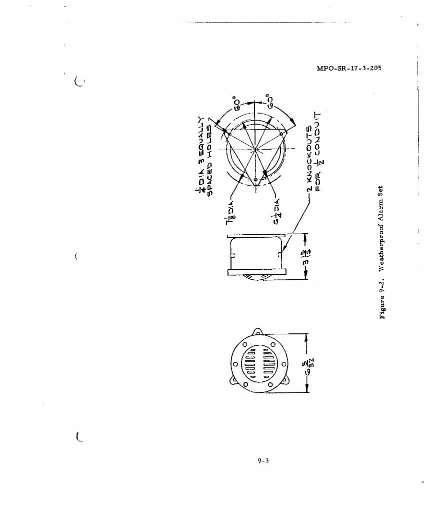
MPO-SR-17-3-205
0000
114
0'
'.4
;Z4
o~~o l
(__9-k
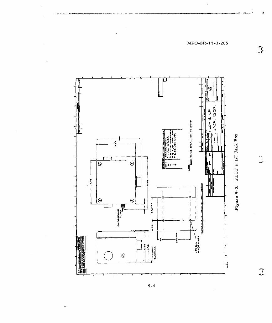
MPO-SR- 17-3-205
3
-I!7-' it
INL
9-4d
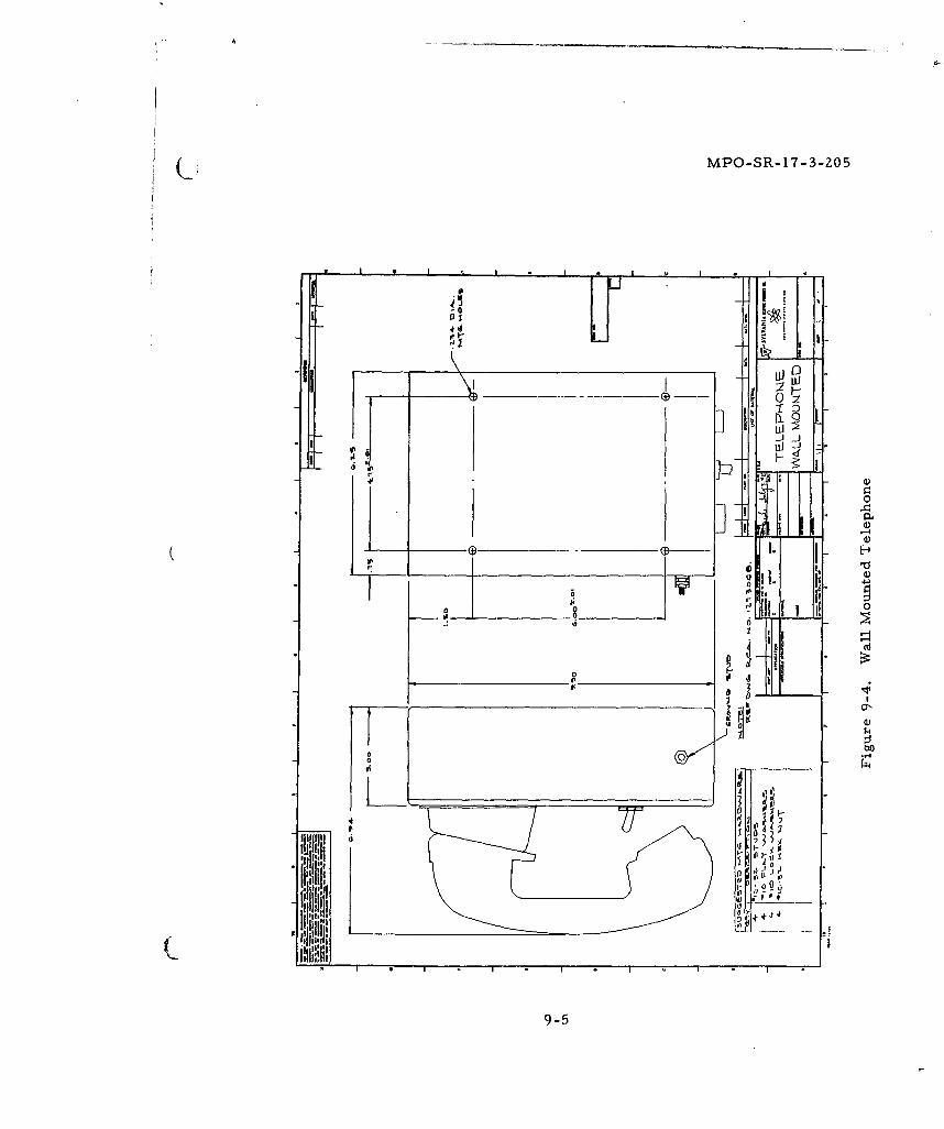
U MPO-SR- 17- 3-ZOS
4'd -.
-. ~ Id
-I d
I--
9-54