Embed Size (px)
Citation preview

UNCLASSIFIED
AD NUMBER
LIMITATION CHANGESTO:
FROM:
AUTHORITY
THIS PAGE IS UNCLASSIFIED
AD816454
Approved for public release; distribution isunlimited. Document partially illegible.
Distribution authorized to DoD only;Administrative/Operational Use; JUL 1967. Otherrequests shall be referred to ArnoldEngineering Development Center, Arnold AFB, TN.Document partially illegible.
USAEDC ltr, 12 Jul 1974

AEDC-TR-67-86
ARCHIVE COPY DO NOT LOAN
d 3 pj, -
ru ■ ^4 > ^^dl ^3 cc a 3 <
t£
3 m 3 * _
=a 3 Sä
i rn =^o ~
= " 'P i □
~ o ' ; 5 u
(- u
^=o 2 ^=fy a = hi < o s - .in z^: ' '
A r
ALTITUDE TESTING OF THE J-2 ROCKET ENGINE
IN PROPULSION ENGINE TEST CELL (J-4)
(TESTS J4-1554-01 THROUGH J4-1554-11)
ThlsdoT^L^
W. W. Muse and 0. E. Franklm ^^^ *?' ^^
ARO, Inc.
July 1967
to special gn govern
e only with priW approval a^FligkCenterd-E-JJ
Each trapsmittal ofl this document outsyi#--cn»-Nye- partmept of Defens« rauet have nrfor approval of
NAS^f Marshall Spaceflight CejU^KI-E-J), Huntsville, Alabama.
LARGE ROCKET FACILITY
ARNOLD ENGINEERING DEVELOPMENT CENTER
AIR FORCE SYSTEMS COMMAND
ARNOLD AIR FORCE STATION, TENNESSEE
-r- :• o /.in FORCE pr. . .,
A;-" ,I;;CJO;12QO

mim When U. S. Government drawings specifications, or uthcr data are used for any purpose other than a definitely related Government procurement operation, the Government thereby incurs no responsibility nor any obligation whatsoever, and the fact that the Covernmeni may have formulated, furnished, or in any way supplied the said drawings, specifications, or other data, is no: to be regarded by implication or otherwise, or in any manner licensing the holder or any other person or corporation, or conveying any rights or permission to manufacture, use, or sei! any patented invention thai may in any way be related thereto.
Qualified users may obtain copies of this report from llie Defence Documentation Center.
References to named commercial products in this report are not to be considered jn any sense as an endorsement of the product by the United States Air Force or the Government.

AEDOTR-67-86
ALTITUDE TESTING OF THE J-2 ROCKET ENGINE
IN PROPULSION ENGINE TEST CELL (J-4)
(TESTS J4-1554-01 THROUGH J4-1554-11)
W. W. Muse and D. E. Franklin
ARO, Inc.
This do^umenft. i and each traasm\ttal to for nationals may
iSA Marshall Sp 'Alabama.
is subject to special export controls ents or foreign,
only with pribt^approval^df
ght Center (I-&J),Huntsville(
ntcr(I-E-J), Huntsville,
This dcCL!r-,-;f!-r^.fr ?,^-ov.,l <c,rn,.fe!iC re[ea5(

AEDC-TR-67-86
FOREWORD
The work reported herein was sponsored by the National Aero- nautics and Space Administration (NASA), Marshall Space Flight Center (MSFC), under System 921E, Project 9194.
The results of the tests presented were obtained by ARO, Inc. (a subsidiary of Sverdrup & Parcel and Associates, Inc.), contract operator of the Arnold Engineering Development Center (AEDC), Air Force Systems Command (AFSC), Arnold Air Force Station, Tennessee, under Contract AF40(600)-1200. Program direction was provided by NASA/MSFC; engineering liaison was provided by North American Aviation, Inc., Rocketdyne Division, the responsible agency for the J-2 engine, and Douglas Aircraft Company, the responsible agency for the S-IVE stage. Testing was conducted during the period from July 30 to November 16, 1966, in Propulsion Engine Test Cell (J-4) of the Large Rocket Facility (LRF) under ARO Project No. KA1554. The manuscript was submitted for publication on April 7, 1967.
Information in this report is embargoed under the Department of State International Traffic in Arms Regulations. This report maybe released to foreign governments by departments or agencies of the U.S. Government subject to approval of NASA Marshall Space Flight Center (I-E-J). Private individuals or firms require a Department of State export license.
This technical report has been reviewed and is approved.
Joseph R. Henry Leonard T. Glaser Lt Colonel, USAF Colonel, USAF AF Representative, RTF Director of Test Directorate of Test
li

AEDC-TR-67-B6
ABSTRACT
Eleven test periods involving a total of 14 J-2 rocket engine starts were accomplished in Propulsion Engine Test Cell (J-4) to verify the engine altitude ignition characteristics and performance in support of the Saturn IB and Saturn V flights. The test article consisted of a flight configuration J-2 rocket engine and a ''battleship" S-IVB stage. Engine ignition characteristics were different from those predicted for altitude testing and provided an important insight into the J-2 engine transient operation for the Saturn IB and Saturn V flights. Transient gas generator outlet temperatures observed were consistently higher than engine acceptance test values. One test resulted in an engine safety cutoff because of an excessive transient gas generator outlet tem- perature. Combustion instability during engine ignition was observed for time durations ranging from 3 to 132 msec for ten of the firings and was similar to the instability recorded during the Saturn IB AS-201 through -203 flights. Excessive engine vibration resulted in an engine safety cutoff on one test. Engine side forces measured at altitude con- ditions were significantly less than those recorded during previous J-2 engine tests. Engine operation time accumulated during these tests was 145. 8 sec.
in

AEDC-TR-67-86
CONTENTS
Page
ABSTRACT iii NOMENCLATURE vii
I. INTRODUCTION 1 II. APPARATUS 2
III. SEQUENCE 11 IV. PROCEDURE 15 V. RESULTS AND DISCUSSION 19
VI. SUMMARY OF RESULTS 37 REFERENCES 38
APPENDIXES
I. ILLUSTRATIONS
Figure
1. Saturn S-IB and S-V Launch Vehicle 41
2. J-2 Engine, S/N 2052 42
3. Aerial View of Test Cell J-4 44
4. J-2 Engine and S-IVB Flight Stage Assembly 45
5. Details of the J-2 Engine 46
6. Details of the J-2 Engine Thrust Chamber ...... 47
7. Details of the J-2 Engine Injector 48
8. Details of the Augmented Spark Igniter 49
9. Schematic of the S-IVB Stage/J-2 Engine 50
10. Cutaway Drawing of Test Cell J-4 51
11. Test Cell J-4 Consumable Storage Systems, Plan View 52
12. Installation of the J-2 Engine/S-IVB Battleship Stage in Test Cell J-4 53
13. Instrumentation Locations of the J-2 Engine 55
14. Maximum and Minimum Allowable Limits for GGOT 59

AEDC-TR-67-86
Figure Page
15. Mechanical Schematic of the J-2 Engine 61
16. Logic Schematic of the J-2 Engine Start 62
17. Selected Engine Parameters for a Typical J-2 Engine Start Transient 6 3
18. Start Transient Comparison of Selected Engine Parameters, Firing 10B 64
19. Effects of Fuel System Resistance on ES Transient Operation 67
20. Effects of Fuel Start Tank Energy on ES Transient Operation 69
21. Hydraulic Torque Effects on MOV Second-Stage Initial Opening Time 71
22. Effects of MOV Second-Stage Opening Time on GGOT Second Peak 72
23. GGOT, Start Transient, Firing 1 IB 73
24. Engine Side-Force Data 74
25. Thrust Chamber Pressure Fluctuations during the ES Transient 75
26. Fuel Pump Start Transient Performance 76
27. Fuel Lead Effects 77
28. Typical J-2 Engine Shutdown Transient 78
29. Thrust Chamber and Gas Generator Propellant Flow Rates versus PU Valve Position 79
30. Fuel Start Tank Repressurization and Warmup Data, . . 81
31. Pre-Fire Warmup Trends of the J-2 Engine Thrust Chamber 83
II. TABLES
I. List of Engine Modifications at AEDC 84
II. List of Engine Component Replacements 85
III. Instrumentation Designation of Selected Parameters . . 86
IV. Engine Purge Sequence at AEDC 93
VI

AEDC-TR-67-B6
II. TABLES (Continued)
Page
V. Summary of Test Conditions and Results 94
VI. Engine Site Performance Summary 95
VII. S-IVB Stage Performance Summary 97
VIII. AEDC Test Matrix 98
IX. Start Transient Operating Times of SeLected Engine Valves 99
X. Shutdown Transient Operating Times of Selected Engine Valves 100
XI. Test Measurements Required by Performance Program 101
NOMENCLATURE
A Area, in.2
ASI Augmented spark igniter
ES Engine start, designated as the time that He control and ignition phase solenoids are energized
ESCS Engine safety cutoff system
GG Gas generator
GGOT Gas generator outlet temperature
GSE Ground support equipment
MOV Main oxidizer valve
O/F Oxidizer-to-fuel propellant mixture ratio
PU Propellant utilization
STDV Start tank discharge valve
t0 Defined as the time at which an opening signal is applied to the STDV solenoid
VSC Vibration safety count, an indicator of the time duration of engine vibration in excess of 150 g
Vll

AEDC-TR-67-86
SUBSCRIPTS
e Exit
f Force
fc Full closed
fo Full open
fp Fuel poppet
ic Initial closing
io Initial opening
m Mass
op Oxidizer poppet
t Throat
Vlll

AEDC-TR-67-86
SECTION I INTRODUCTION
The J-2 rocket engine was designed and developed under contract to the National Aeronautics and Space Administration (NASA) by North American Aviation, Inc., Rocketdyne Division, for the Saturn IB and Saturn V launch vehicles (Fig. 1) in support of the NASA Apollo Pro- gram to explore the surface of the moon and for subsequent outer space missions. The J-2 (Fig. 2) is a 200, 000-lbf-thrust class, multiple restart engine utilizing LO2 and LH2 as propellants.
During early June, 1965, preliminary discussions were held between representatives of AEDC and NASA regarding the feasibility of conducting tests with the J-2 rocket engine in its S-1VB stage configuration in the Propulsion Engine Test Cell (J-4) of the Large Rocket Facility (LRF) (Fig. 3, Ref. 1). A need for static testing of the J-2 engine at altitude con- ditions to verify the engine ignition characteristics and performance in the range of conditions expected on the early Saturn flights was recog- nized by NASA. Altitude testing at AEDC would allow the J-2 engine to be subjected to conditions near the expected space environment and would provide a facility to investigate engine difficulties in the event that any were encountered in the altitude verification tests or in the early Saturn flights. An environmental verification program at AEDC was desired because the program cost would be only a fraction of the amount required to evaluate the integrity of the J-2 engine during a Saturn vehicle flight. On August 27, 1965, NASA authorized the J-2 Engine Environmental Verification Test (EVT) Program to proceed, The objectives of the test program were originally established as follows:
1. Primary Objectives
a. Simulate engine thermal conditions for both single burn and restart applications of the J-2 engine and evaluate the start transient characteristics at a pressure altitude of approxi- mately 100, 000 ft.
b. Evaluate thrust chamber side-force characteristics and engine performance.
c. Evaluate thrust chamber temperatures at engine start (ES) and the He usage for the simulated boost phase and orbital coast conditions.
2. Secondary Objectives
Acquire data to update the J-2 engine start and shutdown conditions and to better define the engine operating limits.

AEDC-TR-67-86
Certain facility modifications were necessary for the conduct of the test program, the most significant being the addition of a testing capa- bility for LH2-fueled engines. The S-IVB "battleship" stage arrived at AEDC on February 22, 1966; the J-2 engine arrived on March 4, 1966. The installation of the test article began on April 16, 1966.
Eleven test periods involving a total of 14 ES and 145. 8 sec of engine operation were accomplished at pressure altitude conditions from July 30 to November 16, 1966. The original program commit- ments called for the initial test to be conducted in July 1966. In view of unpredicted start transient characteristics on the early tests, addi- tional emphasis was placed on the investigation of engine transient characteristics. As a result, the test objectives for the 11 tests reported herein were revised as follows:
1. Evaluate the engine transient operation and performance at a pressure altitude of approximately 100, 000 ft.
2. Acquire data to better define the engine operating conditions and limits for flight applications.
SECTION II APPARATUS
2.1 TEST ARTICLE
The test article was an S-IVB stage of the Saturn IB and Saturn V vehicles and was comprised of the J-2 rocket engine (S/N 2052), designed and developed by Rocketdyne, a division of North American Aviation, Inc., and an S-IVB battleship stage, designed and developed by the Douglas Aircraft Company. The integrated J-2 engine and S-IVB flight stage assembly is presented in Fig. 4.
The J-2 rocket engine is a multiple-restart engine that utilizes LO2 and LH2 as propellants and is designed to be used singly or in clusters. Thrust rating of the engine is 225, 000 lbf at an oxidizer-to- fuel mixture ratio (O/F) of 5. 5.
The boilerplate-constructed S-IVB stage provides propellant capac- ity for testing the engine in the flight configuration. The fluid dynamics of the stage are identical to the flight vehicle. The weight of the battle- ship stage (excluding propellants) is approximately 60 tons; the weight of a flight stage is approximately 11 tons.

AEDC-TR-67-86
Twenty-seven modifications were made to the engine after accept- ance testing and before shipment to AEDC. A modification having a decided effect on the engine transient operation was the gas generator (GG) control system orifice modification. Engine modifications and unsatisfactory component replacements performed at AEDC are pre- sented in Tables I and II, respectively.
2.1.1 J-2 Rocket Engine
The J-2 rocket engine (Fig. 5, Ref. 2) features a bell-shaped thrust chamber, an injector, two direct-drive turbopumps, a gas generator, engine valves, engine-mounted electrical and pneumatic controls, and instrumentation. Initial fuel and oxidizer turbopump start impulse is delivered by an engine-mounted start tank which is pressurized with GH2. The nominal engine O/F ratio ranges from 4.5 to 5. 5, depending upon the propellant utilization (PU) valve position. A pneumatic control system is used for engine valve operation and obtains its energy from regulated GHe supplied from an engine-mounted tank. Engine-mounted electrical control packages provide the necessary logic for proper engine sequencing during operation.
The tubular-wall, bell-shaped thrust chamber (Fig. 6) consists of a cylindrical combustion chamber, a 170. 4-in.2 throat area, and a divergent nozzle with an expansion ratio (Ae/A-(;} of 27. 1. The 18. 6-in. - diam combustion chamber is 8. 0 in. long from the injector mounting face to the throat inlet, and the characteristic length <L*) is 24. 6 in. Overall thrust chamber length is 133 in. from the fuel pump low pres- sure duct inlet to the nozzle exit. The thrust chamber body is con- structed of longitudinal stainless steel tubes that are brazed together and are supported by external stiffening bands around the tubes. Thrust chamber cooling is accomplished by fuel flow, which is supplied to a fuel manifold, circulated downward through 180 tubes, and circulated upward through 360 tubes to the thrust chamber injector.
The thrust chamber injector (Fig. 7) is a concentric-orificed {con- centric fuel orifices around the oxidizer post orifices), porous-faced injector. Fuel and oxidizer injector orifice areas are 25.0 and 16.0 in.2, respectively. The porous material, forming the injector face, allows three or four percent of fuel to flow through and cool the face of the injector.
The augmented spark igniter (ASI) unit is mounted on the thrust chamber injector (Fig. 8) and supplies the initial energy source to ig- nite propellants in the main combustion chamber. The ASI chamber is an integral part of the injector (Fig. 7). Fuel and oxidizer are routed
AEDC-TR-67-86
to the ASI combustion area, where they are ignited by two energized spark plugs. A pneumatically operated poppet valve, mounted on the main oxidizer valve {MOV), controls oxidizer flow to the ASI chamber.
The fuel turbopump is an axial-flow pump with direct turbine drive and consists of an inducer, a seven-stage rotor, and a Stator assembly. It is a self-lubricated, high-speed pump with a two-stage turbine and supplies fuel to the thrust chamber at high pressure. A pressurized start tank supplies initial start energy to the turbine; a gas generator supplies a sustained energy source during engine operation. The fuel and oxidizer turbines are gas coupled by an 8-in. -diam crossover duct that directs gases exiting the fuel turbine to the oxidizer turbine inlet. The LH2 enters the turbopump through an 8.0-in. -diam low pressure duct and exits through a 4.0-in. -diam high pressure duct. Nominal steady-state operating speed of the turbopump is 26, 500 rpm at an engine mixture ratio of 5.5.
The oxidizer turbopump is a single-stage centrifugal pump with direct turbine drive. It is a self-lubricated, high-speed pump with a two-stage turbine and supplies L.O2 to the thrust chamber at high pressures. Gases discharged from the fuel turbine pass through the oxidizer turbine and exit through eyelets {total area of 115 in. 2) into the thrust chamber at an area ratio {A/At) ranging from 10. 45 to 11. 40. A percentage of fuel turbine exhaust gas volume is routed directly to the thrust chamber and bypasses the oxidizer turbine during the ES tran- sient to prevent an overspeed of the turbine. When MOV opens to its first stage, the bypass valve is sequenced closed, and a greater volume of fuel turbine exhaust gases is directed to the oxidizer turbine. With the bypass valve closed, a nozzle in the valve bypasses a small per- centage of gas and acts as a calibration device for turbopump perform- ance balance and engine O/P ratio. The LO2 is supplied to the pump through an 8.0-in. -diam low pressure duct and discharged through a 4.0-in. -diam high pressure duct. Nominal steady-state operating speed of the turbopump is 8500 rpm at an engine mixture ratio of 5.5.
The gas generator consists of a combustion chamber containing two spark plugs, a pneumatically operated control valve containing oxidizer and fuel poppets, and an injector assembly. The oxidizer and fuel poppets are mechanically linked by an actuator and provide a fuel lead to the gas generator combustion chamber. Spark exciters in the elec- trical control package provide energy to the spark plugs to ignite the propellants flowing through the open poppets into the combustion cham- ber.

AEDC-TR-67-86
The duct from the gas generator outlet directs the hot gases to the fuel and oxidizer turbines.
An engine-mounted, spherical tank is comprised of an integral GH2 start tank and a He tank. The integral tank consists of a 7258-in.3 sphere for H2 with a lOOO-in.^ sphere for He located within it. Pres- surized GH2 in the fuel start tank provides the energy source for spinning the propellant turbines during the starting of the engine. The GH2 for repressurization of the start tank during engine main-stage operation is obtained from the thrust chamber fuel manifold inlet and the fuel injection manifold.
The He tank provides a He pressure supply to the engine control system. A pneumatic accumulator, filled from the He tank, provides the necessary He for an emergency shutdown in case the He tank pres- sure is lost during engine operation.
The main fuel valve is a butterfly-type valve which is spring loaded in the closed position. The valve is pneumatically operated to the open position and pneumatically assisted to the closed position. It is mounted in the fuel high pressure duct between the fuel turbopump and the thrust chamber fuel manifold. A sequence valve mounted on the main fuel valve controls pneumatic pressure to the start tank dis- charge valve (STDV) solenoid control valve.
The MOV is a butterfly-type valve, spring loaded in the closed posi- tion. The valve, which opens in two stages, is pneumatically operated to the open position and pneumatically assisted to the closed position. It is mounted in the oxidizer high pressure duct between the oxidizer turbopump and the oxidizer injector manifold. A sequence valve on MOV controls pneumatic pressure to the gas generator control valve.
The electrically operated PU valve is a motor-driven valve that bypasses a percentage of L.O2 from the discharge side of the oxidizer turbopump to the pump inlet side. Nominal O/F ratio range control with the PU valve is 4.5 {full open) to 5. 5 (full closed) over an angle position change of 5 7 deg. The purpose of the PU valve during flight application is to ensure the simultaneous exhaustion of the contents of the vehicle propellant tank. During engine flight, propellant level sensors in the vehicle propellant tanks control the valve position for adjusting oxidizer flow. At AEDC, the PU valve position was con- trolled from the J-4 Control Room.
An engine-mounted pneumatic control package controls pneumatics required for all pneumatically operated valves and engine-supplied

AEDC-TR-67-86
purges. Valves controlled with the pneumatic package include the main fuel valve, first and second stages of MOV, the oxidizer turbine bypass valve, the ASI oxidizer valve, purge control valve, and the fuel and oxidizer bleed valves. Purges of He to the main injector oxidizer dome and the gas generator oxidizer injector are supplied from the pneumatic package.
An engine-mounted, electrical control package provides the logic required for proper sequence of the engine components during opera- tion. The electrical control package contains a sequence controller, to properly sequence engine start and shutdown, and a spark ignition system that energizes the gas generator and ASI spark plugs.
Primary and auxiliary flight instrumentation packages contain sensors required to monitor critical engine parameters. The packages provide environmental control for the sensors.
2.1.2 S-IVB Battleship Stage
The S-IVB battleship stage (Fig. 9) has an internal volume of 10, 456 and 2822 ft^, respectively, for fuel and oxidizer, which provides an approximate propellant maximum capacity of 46, 000 lb of LH2 and 199, 000 lb of LO2. The stage has an internal diameter of 21. 6 ft and is approximately 49 ft long. Propellant prevalves, in the low pressure ducts interfacing the stage and the engine, contain propellants in the stage until being admitted into the engine (to the main propellant valves) to chill the engine propellant supply systems. Propellant recirculation pumps in the vehicle tankage are utilized to circulate propellants through the low pressure ducts and turbopumps for hardware chilldown purposes before ES.
2.2 TEST CELL
Test Cell J-4 (Fig. 10) is a vertically oriented test unit designed for static testing of large liquid-propellant rocket engines and entire propulsion systems at pressure altitudes of 100, 000 ft. The basic cell construction provides a 1.5 million-lbf-thrust capacity. A general description of the features and operating principles of Test Cell J-4 in the subsequent paragraphs can more readily be presented using Fig. 10 as an orientation guide. Reference 1 provides a more detailed descrip- tion of the test cell.
The installation of the J-2 engine/S-IVB battleship stage inside the test capsule orients the engine vertically downward on the centerline of

AEDC-TR-67-86
the diffuser-ejector assembly. The basic dimensions of the test capsule are 48 ft in diameter and 81 ft in height. The diffuser insert (13.5 ft in diameter by 30 ft long) was sized for the J-2 engine to provide engine/ diffuser pumping for meeting the program aLtitude requirements. The diffuser insert is mounted at the inlet of the 20-ft-diam by 150-ft-long diffuser. The centerbody steam ejector in the 20-ft-diam diffuser is provided for pre-fire pumpdown of the test capsule to the desired pres- sure altitude and for significantly reducing blowback at engine shutdown. The GN2 annular ejector, mounted at the inlet of the diffuser insert, is provided to essentially eliminate steam blowback at steam ejector shut- down. A test capsule GN2 repressurization system is provided to pre- vent steam blowback during the steam ejector operation transition and to repressurize the test capsule after engine shutdown.
A concrete spray chamber is provided directly beneath the test capsule to cool and dehumidify the rocket exhaust gas and steam ejector flow. This chamber is 100 ft in diameter and 250 ft deep. Suspended within the spray chamber are the diffuser-ejector system, a film-cooled exhaust deflector plate, three levels of water spray rings, and an LN2 cell inerting and R-factor system. The lower 71 ft of the chamber {that portion below the bottom of the flame deflector) is used for spray water accumulation during a firing. During engine operation, the exhaust gases are collected by the diffuser for dynamic pressure recovery and discharged into the spray chamber. The deflector plate assists in turn- ing the exhaust gas flow from the diffuser upward within the two million -ft 3 spray chamber. The expansion of the exhaust gases in this large volume results in further dynamic pressure recovery and therefore a reduction in their velocity. This low velocity, in combination with the long flow path to the three evacuation ports just beneath the spray chamber cap, causes a significant exhaust gas dwell time in the spray chamber. The water spray system (262, 000-gpm) utilizes this dwell time to effectively cool and dehumidify the exhaust gases. This reduces exhaust mass flow rate by 85 percent. However, N2 must be introduced at about 10 times the mass flow rate of H2 in the exhaust gas for safety considerations and for reducing the gas R-factor value to a level acceptable to the rotating exhaust machinery. The three spray chamber evacuation ports route the cooled gases to a common duct which is connected directly to the exhaust machinery. This machinery provides compression of the gases to atmos- pheric pressure.
The test cell and exhaust ducting are inerted before the transfer of GH2 or LH2 to the stage ana are maintained inert at all times while H2 is aboard the stage. The test cell is considered inert provided the O2 content is less than 4.9 percent by volume. An LN2 system, injecting into the spray chamber, is utilized for inerting spray chamber and

AEDC-TR-67-86
exhaust ducting. The water spray system is operated during the inerting process to ensure complete vaporization of N2 after injection. The test cell is maintained inert by a GN2 purge injected at the top of the test capsule. The purge flow rate, established at 3. 2 times the air in- leakage rate, maintains the test cell O2 content below the O2-H2 flam- mability limit.
Certain facility modifications were necessary to conduct this test program, the most significant being the addition of a testing capability for LH2~fueled engines. The modifications involving the bulk of the design, fabrication (or construction), and installation time included (1) vehicle support stand system, (2) diffuser insert, (3) test capsule extension, {4) blast wall extension, (5) GN2 annular ejector, (6) test cell inerting and R-factor system, (7) consumable storage facilities expansion, (8) test capsule inerting purge and repressurization sys- tems, (9) engine environmental system, (10) electrical systems expan- sion, and (11) site preparation.
The engine/vehicle support stand consisted of a support frame, frame-to-stage adapter, and a side-force measuring system. The force measuring system was designed to measure engine pitch and yaw forces up to 20, 000 Ibf (tension or compression) and for in-place cali- bration of the load cells.
A diffuser insert to the inlet of the existing 20-ft-diam diffuser was provided for dynamic pressure recovery of the engine exhaust gases to meet program altitude requirements. The basic dimensions of the water-cooled insert were 13. 5 ft in diameter and 30 ft in length. A GN2 annular ejector, designed for a maximum flow rate of about 500 lbm/sec, was provided at the entrance to the diffuser insert to prevent steam blowback at steam ejector shutdown.
The consumable storage facilities were expanded to include LH2, GH2, GHe, and additional LN2, GN2, and steam (Fig. 11). The steam capacity was extended by installing a tieline between Test Cells J-3 and J-4 accumulators. The existing oxidizer and water storage sys- tems were adequate.
The extension of the test capsule height to 80 ft was necessary to enclose the engine/stage installation. This extension was accomplished by the addition of two 16-ft-high, 48-ft-diam spool sections. The rein- forced concrete blast wall, surrounding approximately 280 deg of the capsule, was extended by 20 to 60 ft above grade.
The test cell inerting and R-factor system was comprised of a LN2 injection system in the spray chamber to reduce the gas constant and
AEDC-TR-67-86
provide an inert atmosphere for the fuel-rich engine exhaust gases. The GN2 test capsule repressurization system was provided for raising the test capsule pressure at engine shutdown to minimize blowback from the spray chamber and for a test capsule emergency purge in the event of a major propellant leak. The test capsule inerting purge system was provided for inerting the air in-leakage with vaporized JLN2.
The expansion of the electrical systems was required to provide the necessary electrical controls and power to the test cell complex. These included modification to existing power distribution centers, con- siderable wiring for control, electrical power, communication, and test area lighting systems, and a cable trench from the control room to test area.
Site preparation consisted of an extension of roadway and railroad networks for access to consumable storage system installations, con- sumable transporters, maintenance, and fire fighting equipment.
2.3 INSTALLATION
The test article installation was comprised of a J-2 engine/S-IVB battleship stage installed vertically (engine oriented downward on the diffuser-ejector assembly) in the test capsule (Figs. 10 and 12). Modi- fications to the test cell complex (Section 2. 2) were necessary for the test article installation and operation.
The installation of the engine and stage was accomplished by re- moving the top sections of the capsule. The stage was installed on the adapter section of the vehicle support stand; the engine was attached to the stage at the gimbal point. The vehicle and engine propellant sys- tems were interfaced by installing the low pressure propellant ducts, and facility propellant fill, dump, vent, and purge systems were mated with the stage fuel and oxidizer tanks. The pitch and yaw thrust meas- urement columns were connected to the thrust chamber outrigger assemblies, and the modular universal flexures were aligned to permit the forces to be transferred to the load cells with interactions less than ±200 lbf. Facility-supplied engine and stage purges, pneumatics, elec- trical control systems, and instrumentation were installed, and the engine-to-stage systems were interfaced.
2.4 INSTRUMENTATION
Instrumentation systems were provided to measure the engine, stage, and facility parameters of interest. Location and designation

AEDC-TR-67-86
of selected engine- and stage-associated instrumentation used through- out this program are presented in Fig. 13 and Table III, respectively. The engine instrumentation was comprised of flight- and facility- supplemented instrumentation. The flight instrumentation, which measures critical engine parameters, was provided by the engine manufacturer and located in primary and auxiliary instrumentation packages on the engine (Fig. 5). The facility-supplemented engine in- strumentation was provided to verify the flight instrumentation data and to measure additional engine parameters.
All pressure measurements were made using strain-gage-type pressure transducers. The facility-supplied transducers were labora- tory calibrated at AEDC against a secondary standard before installa- tion; the flight and many of the stage instrumentation transducer calibrations were provided by the engine and stage manufacturers, respectively. Electrical calibrations, consisting of substituting pre- cision electrical shunt resistances, were used to calibrate the data acquisition systems. Periodic in-place calibrations of selected trans- ducers used to monitor pressures specified as test requirements were accomplished.
Temperature measurements were made using resistance tempera- ture transducers (RTT) and several types of thermocouples. The RTT units were used primarily for measuring the temperatures of the pro- pellants and various engine components. A combination of copper- constantan, iron-constantan, and Chromel -Alumel thermocouples was used to measure engine hardware and facility temperatures. The data acquisition systems for the RTT and thermocouple measurements were calibrated using precision electrical resistance and voltage sub- stitutions, respectively. Data reduction of RTT measurements was obtained from the manufacturer's calibration data. The thermocouples were referenced to a 150°F junction.
Engine side loads were measured using dual-bridge, strain-gage- type load cells. The load cells were laboratory calibrated before installation. The recording systems were calibrated with precision electrical shunt resistances before each test. The measurement of axial thrust was not a program requirement.
Oxidizer and fuel turbopump shaft speeds were sensed by a mag- netic pickup. Each pump produces a "frequency output of 12 pulses per shaft revolution. The calibration of the recording systems was accom- plished by using frequency substitutions.
Engine fuel and oxidizer flow rates were measured with turbine- type flowmeters. The frequency output of the fuel and oxidizer
10

AEDC-TR-67-86
flowmeters was four and six pulses per revolution, respectively. The fuel and oxidizer flow rates through the propellant recirculation system were also monitored with turbine-type flowmeters. Flowmeter calibra- tions were supplied by the engine and stage manufacturer. The asso- ciated recording systems were calibrated using frequency substitution.
Vibrations (vertical plane) produced during engine operation were measured by accelerometers mounted on the oxidizer injector dome. Accelerometers on the fuel and oxidizer turbopumps sensed vibrations in a horizontal plane. The accelerometers were laboratory calibrated at AEDC by shaker tests before installation. Calibrations of the asso- ciated recording systems consisted of frequency-voltage substitutions.
Selected engine valves were instrumented by the engine manufac- turer with linear potentiometers and microswitches.
The types of data acquisition and recording systems used during this program were (1) a multiple-input digital data acquisition system (MicroSADIC®) scanning each parameter at 40 samples per second and recording on magnetic tape, (2) single-input, continuous-recording, analog system (Vidar®) recording on magnetic tape, (3) single-input, continuous -recording, FM systems recording on magnetic tape, (4) photographically recording galvanometer-type oscillographs, (5) direct inking, null-balance, potentiometer-type X-Y plotters and strip charts, and (6) optical data recording. These systems were calibrated as required before each test (atmospheric and altitude cali- brations) for each parameter measured. Television cameras were used to provide visual coverage during an engine firing.
SECTION III SEQUENCE
Facility logic interfaced with engine logic provided the necessary control to (1) start the engine, (2) sequence the engine properly during start and shutdown transients, and (3) terminate a firing in the event of an engine or vehicle stage malfunction.
3.1 FACILITY LOGIC
Facility logic was interfaced with engine logic to monitor and con- trol the engine and stage start and shutdown sequence. The facility logic was controlled from an automatic countdown sequencer programmed
11

AEDC-TR-67-86
by paper tape input. The sequencer was programmed to ascertain firing readiness by sampling system-ready switches 1 sec before fire command. Approximately 0. 2 sec before sequencer "zero", the sequencer initiates a fire command signal which energizes the facility logic; at sequencer zero, the sequencer is programmed to stop until the STDV solenoid is energized.
The propellant prevalves are commanded open at fire command by the facility logic. After both prevalves are open, a 5-sec propellant recirculation "off" timer is energized. A sequence monitor timer is set to terminate the countdown if the combined time required from fire command to expiration of the 5-sec timer exceeds 13 sec. At expira- tion of the 5-sec timer, an ES command is initiated, a facility fuel lead timer is energized, and a facility "start OK" timer is energized. The ES command signal is terminated after 200 msec by a facility timer; at this time, the start command is locked in by the engine logic. The facility start OK timers are provided as engine backup timers to auto- matically terminate a firing if the engine "main-stage pressure OK" signal has not been obtained within a predetermined time period. If, after expiration of the fuel lead timer, the engine starting conditions are satisfied, an open signal will be applied to the STDV solenoid. This signal, which causes the sequencer to restart, is used as engine and sequencer zero reference.
At expiration of run duration, an engine shutdown command is initiated by the facility sequencer. The shutdown command activates the engine and facility cutoff logic. This starts facility-supplied cutoff purges and closes the propellant prevalves.
Selected critical engine parameters are automatically monitored during a firing with the engine safety cutoff system (ESCS) and manually monitored by observers in the control room. Emergency shutdown circuitry is monitored at all times by the facility logic system and initiates an engine shutdown command if any malfunctions occur.
The ESCS was provided to monitor critical engine parameters and to initiate a shutdown command, if predetermined values are exceeded. Parameters monitored were (1) fuel turbine overspeed, (2) engine vibrations, and (3) the gas generator outlet temperatures (GGOT),
An automatic shutdown limit of 23, 400 rpm was established as the maximum allowable fuel turbine speed during engine main-stage opera- tion. The fuel turbine overspeed requirement was deleted after test 03.
12

AEDC-TR-67-86
Sustained engine vibrations in excess of 150 g for greater than 70 msec were established as the automatic "kill" limit through test 05. After test 05, the timer was reset to 150 msec.
Automatic shutdown limits established for GGOT are presented in Fig. 14. The minimum allowable GGOT limit was 250°F at approxi- mately 1. 24 sec after the STDV solenoid energized. The maximum allowable limit was 2000°F from approximately 1. 24 to 3. 94 sec after the STDV solenoid energized. A maximum allowable temperature for steady-state operation was 145 0°F.
3.2 ENGINE SEQUENCE
3.2.1 Engine Start Sequence
An engine schematic and an operating sequence diagram are pre- sented in Figs. 15 and 16. The ES can be initiated after all engine, vehicle, and facility-ready systems have been made, and thereafter each event is sequenced by an engine sequence controller. Initiation of ES command (facility-initiated) activates the ES module, which simultaneously opens the He control valve, the ignition phase control valve, and energizes the spark plug exciters. The start tank discharge control timer and fuel lead timer are also energized at ES command. The He control valve regulates He flow to fill the pneumatic accumu- lator, to close the propellant bleed valves, and to purge the oxidizer dome and gas generator oxidizer injector manifold through the purge control valve. The ignition phase control valve routes He pressure to open the ASI oxidizer valve and the main fuel valve and supplies pres- sure to the inlet port of the sequence valve located within the MOV first-stage actuator. A check valve in the pneumatic control package ensures continued pressure to engine valves in the event of a He supply failure. Once the ASI oxidizer valve and the main fuel valve are opened, propellants flow under static head to the ASI chamber and are ignited. When the main fuel valve is 90 percent open, a sequence valve opens and supplies pneumatic opening pressure to the STDV solenoid control valve.
A normal engine sequence will continue with thr opening of STDV and the energizing of the ignition phase timer (450-msec timer) if the following conditions exist (1) the main fuel valve and fuel sequence valve are open, (2) proper fuel quality at the injector is verified by a fuel injector temperature below -150°F, (3) start tank discharge con- trol timer has expired (640-msec timer initiated at engine start), and (4) the fuel lead timer {facility timer) has expired. With these four
13

AEDC-TR-67-86
conditions satisfied, STDV opens to release GH2 to the fuel and oxidizer turbine. Once the ignition phase timer has expired, STDV is closed by de-energizing the control solenoid, a 3. 3-sec spark plug de-energize timer is activated, and the main-stage control module is energized. If ignition has not been detected (as indicated by the ignition detect probe in ASI) when the ignition phase timer has expired, engine cutoff will occur. After the main-stage control module is energized, the main- stage control valve opens, venting He pressure from the MOV closing actuator and the opening port of the purge control valve. The purge control valve closes, and the oxidizer dome and gas generator oxidizer purges are terminated. Opening pressure is applied to the MOV open- ing actuators, and the MOV first stage opens. A sequence valve in MOV opens and supplies pressure to open the gas generator control valve and close the oxidizer turbine bypass valve. Fuel and oxidizer flow to the gas generator are controlled by poppets in the gas generator control valve that open sequentially to provide a fuel lead. Gases generated are directed in series to the fuel and then oxidizer turbines. The second stage of MOV starts opening approximately 0. 6 sec after the main-stage control valve is opened. The second-stage valve ramp time is controlled by venting closing pressure through an orificed check valve. As the propellant turbopumps approach steady-state operation, the main-stage pressure OK signal is generated (by a pressure switch), and steady- state engine operation follows. If the main-stage pressure OK signal has not been initiated before the sparks de-energize timer expires, engine cutoff will occur. The time from ES command to main-stage pressure OK signal is primarily dependent on the fuel lead time.
3.2.2 Engine Shutdown Sequence
A cutoff signal applied to the sequence controller simultaneously de-energizes the control solenoids for closing the main-stage control and ignition phase control valves and energizes the He control de- energize timer. Opening control pressure for the MOV actuator, ASI oxidizer valve, and main fuel valve is vented through ports in the pneumatic control package. The He pressure is supplied to the closing actuator of MOV, the opening control port of the purge control valve, closing actuator of the ASI oxidizer valve, closing actuator of the main fuel valve, and the opening control port of the pressure-actuated fast shutdown control valve. Oxidizer dome and gas generator oxidizer line purges begin as soon as thrust chamber and gas generator pres- sures drop below the He control pressure level. With the exception of the ASI oxidizer valve, propellant bleed valves, and the oxidizer turbine bypass valve, all valves are spring loaded to the closed position. The oxidizer turbine bypass valve is spring loaded to the open position and
14

fcEDC-TR-47-86
starts to open as soon as closing pressure is vented. When the He con- trol de-energize timer expires, the He control valve closes, and con- trol system pressure is vented through the oxidizer dome and gas generator oxidizer line purges. When He control pressure drops to the actuation pressure level of the normally closed purge control valve, the valve closes, and the purges stop. Closing pressure to the propellant bleed valves is bled off, and these valves open under spring pressure.
SECTION IV PROCEDURE
The major facility modifications necessary to conduct this program required many subsystem checkouts. As subsystems were brought to an operable state, these were integrated with the complete system and checked out to assure proper operation. After the S-IVB stage and J-2 engine were installed in the test cell, all required electrical and mechan- ical hookups were accomplished. Final facility, engine, and stage readiness for a firing was verified in an integrated systems checkout. This checkout, identified as test number J4-1554-01, was conducted on July 30, 1966. All functions required to fire the J-2 engine were ac- complished. A firing was not planned for this test period.
Pre-operational procedures were begun several hours before each test. All consumable storage systems were replenished, and engine inspections and leak checks were conducted. Chemical analysis of pro- pellants, propellant tank pressurants, and engine pneumatic and purge gas samples was made to ensure that test specifications were met. Facility and engine sequence checks and engine abort checks were con- ducted within a 24-hr time period before an engine firing to verify the proper sequence of events. The abort checks consisted of electrically simulating engine malfunctions to verify the occurrence of a cutoff signal in the event of such a malfunction during engine operation. Engine and facility sequence checks consisted of verifying the timing of all engine and facility valves and events to be within specified limits. A final engine sequence check was conducted immediately preceding the cell evacuation for a test period.
Upon completion of atmospheric instrumentation calibrations, the test cell was evacuated to approximately 0. 5 psia with the exhaust machinery; altitude instrumentation calibrations were conducted; and subsequently, a cell air in-leakage evaluation was performed. Oxidizer dome, gas generator oxidizer injector, and thrust chamber jacket purges were initiated before evacuating the test cell (engine purges
15
AEDC-TR-67-86
required for a typical test period are presented in Table IV). Imme- diately before loading propellants on board the vehicle, the cell and exhaust ducting atmosphere was inerted with approximately 20, 000 lb of N2 to reduce the O2 content to less than 4. 9 percent by volume (lower flammability limit of H2-O2 mixtures). At this same time, the cell N2 purge was initiated at a rate equivalent to the cell air in- Leakage multiplied by 3. 2. This cell purge (6- to 10-lb/sec) continu- ously inerted the air leaking into the cell for the duration of the test period. The vehicle propellant tanks were then loaded to the 30-percent level (a test requirement maximum), and the remainder of the terminal countdown was conducted. A typical countdown was as follows:
Time
t0 - 6 hr 1.
2.
3.
t0 - 5 hr, 1. 45 min
t0 - 5 hr, 30 min
t0 - 4 hr, 45 min
tQ - 4.00 hr
t0 - 3 hr, 45 min
Event
Initiate oxidizer dome and gas generator oxidizer injector He purges.
Initiate low level thrust chamber jacket He purge.
Evacuate test cell.
1. Cut off oxidizer dome and gas generator oxidizer injector He purges.
2. Initiate oxidizer dome GN2 purge.
Calibrate instrumentation at altitude conditions.
Evaluate test cell air in-leakage.
1. Increase thrust chamber jacket He purge to high level.
2. Inert cell with N2.
3. Initiate cell GN2 purge.
1. Reduce thrust chamber jacket He purge to low level.
2. Transfer propellants to the vehicle tanks.
t0 - 1 hr, 10 min
to - 1 hr
Initiate a 10-min turbopump and gas generator He purge.
1. Increase thrust chamber jacket He purge to high level.
2. Open fuel and oxidizer prevalves and temperature condition propellants.
16

AEDC-TR-67-36
Time
t0 - 51 min
t0 - 50 min
t0 - 46 min
t0 - 45 min
tr» - 15 min
t0 - 660 sec
t0 - 600 sec
t0 - 590 sec
t0 - 240 sec
t0 - 200 sec
t0 - 150 sec
tn - 130 sec
tn - 120 sec
t0 - 100 sec
t0 - 80 sec
t0 - 70 sec
t0 - 60 sec
Event
Initiate start tank purge.
1. Cycle fuel and oxidizer tank vent valves.
2. Open propellant recirculation valves.
Condition the fuel start tank.
Reduce thrust chamber jacket He purge to low Level.
1. Cut off thrust chamber jacket low level He purge.
2. Temperature condition the thrust chamber.
3. Cut off oxidizer dome GN2 purge.
Initiate remainder of countdown on automatic sequence timing.
Start propellant recirculation pumps.
Close fuel and oxidizer prevalves.
Initiate turbopump and gas generator He purges.
Initiate partial spray chamber water coolant flow.
Pressurize the oxidizer vehicle tank.
1. Increase cell GN2 purge to maximum flow.
2. Begin cell GN2 repressurization flow maximum rate,
1. Initiate LN2 flow at 50 lb/sec.
2. Pressurize the-fuel vehicle tank.
Cut off turbopump and gas generator He purges.
1. Increase MicroSADIC to maximum sampling rate.
2. Start analog strip recorders.
3. Turn on cell photograph lights.
4. Initiate remainder of spray chamber water coolant flow.
Start the motion-picture cameras.
Initiate a 20-sec ramp of steam ejector driving pressure to initial level (100-psia).
17

AEDC-TR-67-86
Time Event
tQ - 25 sec 1. Cut off cell GN2 purge.
2. Cut off cell GN2 repressurization flow.
3. Increase LN2 flow to 75 lb^sec
to - 20. 5 sec Automatic hold, if exhauster plant and coolant flow systems are not ready to proceed into firing.
t0 - 10 sec Initiate high-speed analog recorders.
t0 - 1 sec Automatic hold if control systems and/or start requirements are judged unsatisfactory for firing.
tQ 1. Initiate fire command. The sequencer is pro- grammed to hold until the engine STDV solenoid is energized and then resumes the count.
2. Increase LN2 flow to 300 lbm/sec
tQ + 59 sec Initiate GN2 ejector flow of 475 lbm/sec.
t0 + 60 sec 1. Initiate engine cutoff signal.
2. Initiate maximum cell GN2 interdiffuser and re- pressurization flow.
t0 4 62 sec Cut off deflector plate coolant water.
tQ + 65 sec Initiate 25-sec cutoff ramp of steam ejector driving pressure.
tQ 4 75 sec Cut off motion-picture cameras.
t0 4 80 sec 1. Initiate 15-sec cutoff ramp of GN2 ejector flow.
2. Cut off cell photograph lights.
t0 4 85 sec 1. Reduce MicroSADIC sampling rate,
2. Cut off high-speed analog recorders.
t0 4 95 sec 1. Reduce spray chamber water coolant flow.
2. Reset engine firing panel - de-energize engine ignition and control power buses.
t0 4 100 sec Vent vehicle fuel and oxidizer tanks.
t0 4 200 sec Cut off LN2 flow,
t0 + 210 sec Cut off remaining spray chamber water coolant.
t0 4 300 sec Initiate vehicle fuel and oxidizer detanking.
t0 4 370 sec Cut off GN2 interdiffuser purge.
18

AEDC-TR-67-B6
Time Event
t0 + 660
t0 + 15 min
tQ + 1 hr
t0 + 2 hr
t0 + 2 hr, 15 min
t0 + 3.00 hr
1. Cut off turbopump and gas generator He purges,
2. Cut off oxidizer dome GN2 purge.
3. Cut off thrust chamber jacket He purge
Vent and purge fuel start tank.
Initiate purging and inerting of vehicle fuel and oxi- dizer tanks after detanking is completed.
Initiate post-fire cell N2 inerting,
Conduct post-fire altitude instrumentation calibrations<
Return test cell pressure to atmospheric level.
SECTION V RESULTS AND DISCUSSION
5.1 GENERAL
The objectives of the first 11 test periods of the J-2 Engine EVT Program are outlined below:
1. Evaluate the engine transient operation and performance at a pressure altitude of approximately 100, 000 ft.
2. Acquire data to better define the engine operating conditions and limits for flight applications.
These objectives were accomplished primarily utilizing the start condi- tions for the J-2 engine Saturn IB flight applications. However, some tests included objectives in support of the J-2 engine restart application the S-IVB stage of the Saturn V.
Test conditions and results and selected engine and stage perform- ance parameters are summarized in Tables V through VII. The test matrix outlining the required target conditions for ES is presented in Table VIII. AU ES were accomplished with the PU valve in null posi- tion (O/F ratio of 5. 0).
Since the data presentation will be directed toward detailed discus- sion of engine systems operation, pertinent comments for each test period will be presented initially. Optimum facility steam ejector per- formance was not realized on earlier tests. This was because proper sequencing of facility systems was being developed during these tests and resulted in the engine being subjected to a low pressure altitude
19

AEDC-TR-67.8*
and a steam environment at ES. Three firings (05, 06, and 09A) were conducted without facility steam ejector operation. Firing durations were progressively increased, consistent with the development of facility operational procedures, to a maximum of 40 sec in working toward a 60-sec firing goal (a 60-sec firing duration is required for the engine to attain thermal equilibrium).
5.1.1 J4-1554-01
Test Date July 30, 1966
Test 01 was a readiness and reliability checkout of all engine, stage, and facility systems and involved an integrated countdown of all systems. An engine firing was not scheduled; however, all functions necessary for a normal firing were accomplished.
The engine MOV assembly was replaced before test 02 to incorpo- rate a temperature compensating orifice.
5.1.2 J4-1554-02
Test Date August 26, 1966 Pressure Altitude at ES, ft 67,000 (Ref. 3) Firing Duration, sec 1.169
The programmed 20-sec engine firing was terminated prematurely by ESCS, which sensed a fuel turbine overspeed. Analysis of the fuel turbine speed data revealed the occurrence of a faulty engine cutoff since turbine speed was well within the spinup specifications. The source generating the cutoff signal could not be isolated. However, provisions were made to record the output signal from the fuel turbine tachometer on subsequent tests to investigate the possibility of its generating the signal level for cutoff.
A maximum GGOT of 1700°F occurred. This peak temperature was considerably higher than observed for engine acceptance tests at lower engine ambient altitude conditions. Sporadic vibration safety counts (VSC) were observed for 30 msec; no VSC were expected. Maximum chamber pressure attained was 80 psia.
5.1.3 J4-1554-03
Test Date September 2, 1966 Pressure Altitude at ES, ft 77, 400 Firing Duration, sec 1. 052
The ESCS again sensed a fuel turbine overspeed and prematurely terminated the engine firing scheduled for 20-sec duration. The fuel
20

AEDC-TR-67-B6
turbine speed was again within the spinup specifications, which indi- cated the reoccurrence of a faulty engine cutoff. The analysis of wave form of the turbine tachometer output signal revealed two peaks per cycle, both of which were being counted by the ESCS overspeed trip circuitry. The double counting of the true turbine output signal fre- quency was concluded as the source of the faulty engine cutoff for this test and for test 02. As a result, this automatic shutdown circuit was deleted from ESCS for subsequent tests.
An extremely high GGOT spike of 2230°F occurred before engine shutdown. Engine VSC were encountered for 12 msec. Maximum chamber pressure attained was 137 psia.
5.1.4 J4-1554-04
Test Date September 14, 1966 Pressure Altitude at ES, ft 6 7, 000 Firing Duration, sec 1.082
The programmed 20-sec firing was terminated by ESCS for exces- sive VSC duration. Engine cutoff occurred after 112 msec of sporadic VSC; however, the VSC duration continued for 20 msec during engine shutdown. A maximum GGOT of 1880°F was recorded at engine shut- down. Maximum chamber pressure attained was 145 psia.
Since there were possibilities of injector icing resulting from the engine environment at ES, an improved oxidizer dome purge diffuser was installed, and the purge diffuser GNo supply was heated.
5.1.5 J4-1554-05
Test Date September 24, 1966 Pressure Altitude at ES, ft 53, 000 Firing Duration, sec 10. 075
A 10-sec firing was successfully conducted to achieve the first main-stage operation of the J-2 engine at AEDC. Engine 90-percent performance level (thrust chamber pressure of 600 psia) was attained at 2. 108 sec. Sporadic VSC were experienced for 67 msec. A peak GGOT of 1860^ was recorded. Side forces produced during the engine tran- sient operation were considerably reduced from engine acceptance tests and were within acceptable limits. The automatic shutdown limit for sustained VSC was changed from 70 to 150 msec for subsequent tests.
21

AEDC-TR-67-86
5.1.6 J4-1554-W
Test Date September 30, 1966 Pressure Altitude at ES, ft 58, 000 Firing Duration, sec 10. 075
The engine firing was successfully conducted for the programmed 10 sec. Engine 90-percent performance level was attained at 2.133 sec. Engine VSC were not observed. A peak GGOT of 1740°F was recorded.
5.1.7 J4-1554-07
Test Date October 7, 1966 Pressure Altitude at ES, ft 72, 800 Firing Duration, sec 20. 070
The programmed 20-sec firing was successfully accomplished. Engine 90-percent performance level was attained at 2. 133 sec. Sporadic VSC were recorded for 30 msec; a peak GGOT of 1650°F was indicated. A malfunction in the prechill controller system permitted the ignition phase timer to be enabled, even though the fuel injector temperature (-74°F) was considerably warmer than the level (-150°F) required. A faulty fuel injector temperature probe produced this anomaly. It is significant that no fuel pump low-speed stall occurred because of the rapid thrust chamber chilldown during the ES transient at altitude conditions.
The oxidizer injector dome purge diffuser was replaced with a standard ground support equipment (GSE) diffuser before test 08.
5.1.8 J4-1554-08
Test Date October 18, 1966 Pressure Altitude at ES, ft 75, 000 Firing Duration, sec 20. 078
The engine firing was successfully conducted for the programmed 20 sec. Engine 90-percent performance level was attained at 2. 225 sec. Sporadic VSC were recorded for 15 msec. Peak GGOT of 1740°F was indicated.
22

AEDC-TR-67-86
5.1.9 J4-1554-09
Test Date October 27, 1966
Test 09A Test 09B
Pressure Altitude at ES, ft 62, 000 93, 000 Firing Duration, sec 5.068 0.454
The programmed 5-sec engine firing for test 09A was successfully accomplished. Engine 90-percent performance level was attained at 2. 108 sec. Engine VSC were recorded for 3 msec. The peak. GGOT was 1700°F. Before test 09A, an engine chilldown procedure was evaluated which involved temperature conditioning the hardware asso-- elated with the propellant low pressure ducts and turbopumps using the vehicle propellant recirculation systems.
Test 09B, programmed for 0. 4-sec duration and including an 8-sec fuel lead with no prior thrust chamber temperature conditioning, was successfully conducted in support of an engine restart study. The LH2 temperature at the fuel injector after the 8-sec fuel lead was the deciding factor for a 4.5-sec fuel lead on test 10B.
5.1.10 J4-1554-10
Test Date November 4, 1966
Test 10A Test 10B Test 10C
Pressure Altitude at ES, ft 102, 500 109, 000 109, 000 Firing Duration, sec 5.070 30.068 N/A
The programmed 5-sec engine firing for test 10A was successfully accomplished. Engine 90-percent performance level was attained at 2. 100 sec. Engine VSC were recorded for 23 msec. The transient GGOT indicated two peaks of significance. The initial peak was 1910°Fj the second peak was 1880°F.
The engine firing for test 10B was successfully accomplished for the programmed 30-sec duration. Engine 90-percent performance level was attained at 2. 116 sec. This test was the initial engine restart test. Engine VSC were not observed. The GGOT again exhibited two transient peaks. The initial peak was 1590°F; the second peak was 1680°F. The second GGOT peak was the first GGOT overshoot experienced.
Test 10C, which did not involve an engine firing, was conducted to evaluate an engine/stage chilldown procedure for temperature conditioning
23

AEDC-TR-67-86
the hardware associated with the propellant low pressure ducts and turbopumps for engine restart.
5.1.11 J4-1554-11
Test Date November 16, 1966
Test 11A Test 11B Test 11C
Pressure Altitude at ES, ft 108,000 105,500 108,700 Firing Duration, sec 40.070 1.378 0.071
The programmed 40-sec engine firing for test 11A was successfully accomplished. Engine 90-percent performance level was attained at 2. 100 sec. This test was the first engine firing during this program with a PU valve excursion. The PU valve excursion, at approximately 5 sec, effectively changed the engine mixture ratio from 5.0 to 5.5. Sporadic VSC were indicated for 83 msec. Two transient GGOT peaks were observed; the initial peak was 1790°F, and the second peak was 1730°F.
Test 11B, programmed for a 5-sec engine firing duration, was terminated prematurely by ESCS for a GGOT transient overtemperature. A GGOT overshoot temperature of 2150°F exceeded the automatic cutoff limit; the initial GGOT peak was 2000°F. Engine VSC were recorded for 20 msec. This was the first engine firing attempt with an 8-sec fuel lead.
Test 11C, which did not involve an engine firing, was conducted to evaluate an engine/stage chilldown procedure for temperature condition- ing the hardware associated with propellant low ducts and turbopumps for engine restart.
5.2 ENGINE TRANSIENT OPERATIONS
The J-2 engine transient operations during this program revealed characteristics somewhat different from the engine acceptance tests and provided an important insight into the engine transient operation for the Saturn IB and Saturn V flights. The presentation will first be devoted to establishing relationships between the basic parameters for start tran- sient analysis by using data from test 10B and then followed by discus- sions of the transient gas generator operation, thrust chamber side forces, combustion instability, fuel pump transient performance (head- flow characteristics), fuel lead effects, and engine shutdown transient.
24

AEDC-TR.67-86
5.2.1 Typical ES Transient
The relationship between basic engine parameters is established in this start transient section utilizing test 10B data. Data reference time is STDV solenoid energized. Before the reference time, the ES com- mand had been initiated and the main fuel valve opened. Start transient traces for valve operations and basic engine parameters are presented in Fig. 17. Selected engine valve operating times for all firings are shown in Table IX.
The spinup characteristics of the fuel and oxidizer turbines during ES are presented in Fig. 18a. As initial opening of STDV occurs, start tank pressure supplies energy to both turbines. Initial STDV movement for test 10B occurred at 0. 158 sec and was fully open at 0. 315 sec. A peak oxidizer turbine speed of approximately 3550 rpm was observed to occur at 0. 7 sec as a result of start tank blowdown. Fuel turbine speed continually increased, although at a reduced rate after 0.6 sec. The STDV started closing at 0. 535 sec and was fully closed at 0. 840 sec. An increase in start tank pressure was noted at 1 sec after STDV as a result of normal repressurization. Initial gas generator combustion occurred at 0. 621 sec and continued the supply of operating energy for the turbines. Typical start transient fuel and oxidizer turbine inlet temperatures and the oxidizer turbine inlet pressure are shown in Fig. 18b. The fuel pump turbine inlet pressure was not measured but was similar to that of the gas generator chamber pressure, also shown in Fig. 18b.
The initial gas generator chamber pressure and fuel injector pres- sure spikes (Fig. 18c) reflect start tank blowdown. The oxidizer in- jector pressure initially reflects a He purge, which is terminated 0. 44 sec after the STDV solenoid is energized. A check valve in the oxidizer injector prevents backflow when chamber pressure is higher than the injector pressure. Fuel and oxidizer flow to the gas generator is supplied through poppets that are sequentially opened. Initial open- ing of the fuel poppet occurred at 0, 522 sec and was fully open at 0. 575 sec; the oxidizer poppet started to open at 0. 621 sec and was fully open at 0.697 sec. As can be observed in Fig. 18c, gas generator chamber pressure sharply increased when the oxidizer poppet was opened, indicating initial combustion. Note that at approximately 0.85 sec, gas generator chamber pressure exhibited an increase, whereas the oxidizer injector pressure decreased. The gas generator chamber pressure rise resulted from the gradual increase of fuel and oxidizer pump discharge pressures. Apparently the drop in injector pressure resulted from chilldown of the oxidizer bootstrap line (supply line from oxidizer pump discharge to the gas generator injector) resulting
25

AEDC-TR-67-86
in improved oxidizer quality supplied to the gas generator. When thrust chamber ignition occurred {arbitrarily defined in this report as the time that thrust chamber pressure attains 100 psia), a higher resistance to the main fuel and oxidizer flows was developed. Consequently, a rapid increase in fuel pump discharge and gas generator fuel injector pres- sures occurred (Figs. 18c and d). However, only a gradual increase in oxidizer pump discharge and gas generator oxidizer injector pres- sures occurred (Figs. 18c and d) because of resistance being afforded to the oxidizer flow by MOV. As a result, the increase in fuel flow to the gas generator exceeded the increase in oxidizer flow and thereby reduced the gas generator O/F ratio and GGOT. Gas generator tem- peratures recorded for test 10B are shown in Fig. 18c. The peak initial temperature was 1590°F, and the overshoot was 1680°F.
The buildup in fuel pump discharge pressure during start tank blowdown {Fig. 18d) reflected turbine speed buildup. After opening the fuel poppet, the sudden pressure rise noted in fuel pump discharge pres- sure at approximately 0. 55 sec apparently resulted from fuel backflow through the gas generator fuel poppet. An enlarged view, from 0. 5 to 0. 8 sec, of fuel pump discharge pressure and gas generator chamber and injector pressures is shown in Fig. 18e. Ten firings appeared to have fuel backflow. Another pressure spike in fuel pump discharge pressure at approximately 0.64 sec (Fig. 18d) appears to be backflow of hot combustion gases through the fuel poppet. The apparent back- flow of hot gases was unique to test 10B. With the exception of test 10B, pump discharge and injector pressures were high enough to prevent hot gas backflow through the fuel poppet. Thrust chamber ignition, which occurred at 0.973 sec, increased the backpressure by developing re- sistance to propellant flow and caused a rapid rise in the fuel pump discharge pressure.
Oxidizer pump discharge pressure exhibited a rapid increase (Fig. 18d) with turbine spinup. The sharp increase resulted from high oxidizer system resistance caused by the MOV position. The first stage of MOV started opening at 0.494 sec and was fully open at 0. 549 sec. From 0, 60 to 0. 85 sec, little change was noted in the oxidizer pump discharge pressure. At 0. 85 sec the oxidizer turbine bypass valve was approximately 84 percent closed and caused a higher percentage of gas generator exhaust gases to be directed to the oxidizer turbine. The rate of increase of the oxidizer pump discharge pressure exceeds that of the fuel pump discharge pressure from approximately 1- 00 to 1. 20 sec. With the opening of the MOV second stage, the fuel pump discharge pressure began to converge on the oxidizer pump dis- charge pressure (Fig. 18d) until about 1.37 sec, afterwards, the rise rates of both pressures remained relatively constant until 1.80 sec. At this time, the pump discharge pressures were approaching steady-state levels.
26

AEOC-TR-67-B6
The main fuel injector and thrust chamber pressure exhibited a low rate of increase until thrust chamber ignition occurred (Fig. 18f), at which time pressures increased to approximately 180 and 160 psia, respectively. Both pressures attained steady-state level at about 2.5 sec. Responses of oxidizer injector pressure measurements were inadequate for transient operation study and are not presented.
Fuel and oxidizer flow rates to the engine are presented in Fig. 18f. Fuel flow rate attained approximately 61 percent of steady state by 0. 6 sec after the STDV solenoid was energized. Because of the oxidizer valve operating sequence, increase in oxidizer flow was relatively slow.
5,2.2 Gas Generator Observations
Start transient GGOT recorded at AEDC were consistently higher than observed during acceptance tests. This was attributed primarily to an improved oxidizer quality supply to the gas generator and lower fuel system resistance at altitude conditions during ES. The GGOT ex- perienced have exhibited two peaks; an initial peak occurring approxi- mately 1 sec after the STDV solenoid was energized and a second peak approximately 0. 3 sec later. Since GGOT is a function of propellant O/F ratio in the gas generator, any factor changing fuel or oxidizer flow rate to the gas generator will affect GGOT. Items investigated as possible contributors to the magnitude of the initial peak were (1) fuel system flow resistance, which varies primarily with thrust chamber temperature conditions, (2) the fuel start tank energy, and {3} turbine hardware temperatures (including the crossover duct temperature). These factors, as well as the effect of the MOV opening sequence, were investigated as possible contributors to the GGOT second peak.
5.2.2.1 Fuel System Resistance Effect on GGOT, Initial Peak
A comparison of tests 05 and 07 demonstrates the effect of fuel system resistance on the initial GGOT peak. Fuel system resistance to flow increases as the thrust chamber temperature is increased. Using this criteria, fuel flow resistance was high for test 07 and low for test 05. Specific throat and exit temperatures at ES were:
Test Throat Exit Resistance No. Temperatures, °F Temperatures, °F to Fuel Flow
5 -233 -216 Low 7 -88 -70 High
Start tank energy and oxidizer turbine hardware temperature compared closely for these two tests and hence are considered not to bias the initial GGOT peak.
27

AEDC-TR-67-86
Since the gas generator O/F ratio is dependent on fuel and oxidizer injector pressures, factors affecting these pressures were investigated. The initial start transient fuel pump discharge and gas generator fuel injector pressures (Figs. 19a and b) were observed to increase signifi- cantly with the warmer thrust chamber temperatures for test 07. The oxidizer pump turbine speed (Fig. 19c), pump discharge pressure (Fig. 19a), and gas generator injector pressure (Fig. 19b) were not significantly affected by the difference in fuel system resistance until about 0. 7 sec after STDV. At approximately 0. 6 3 sec, initial combus- tion occurred in the gas generator, and transient "bootstrap" operation was initiated. The higher gas generator chamber pressure observed during test 07, immediately after bootstrapping (Fig. 19d), was pro- duced by increased fuel flow rate resulting from higher fuel system pressures.
The higher gas generator fuel injector pressure caused by higher fuel system resistance should result in a lower O/F ratio and lower the initial GGOT transient peak. This is confirmed by a comparison of initial peak GGOT values recorded for the two firings (Fig. 19d). The initial peak GGOT values were 1860 and 1650°F, respectively, for test 05 (cold thrust chamber) and test 07 (warm thrust chamber). It is concluded that the indicated lower initial peak value of GGOT for test 07 resulted from the higher fuel system resistance caused by the warm thrust chamber temperature conditions.
The initial GGOT peak was quenched by conditions resulting from thrust chamber ignition as discussed in Section 5. 2. 1.
5.2.2.2 Start Tank Energy Effect on GGOT, Initial Peak
The start tank energy effect can be demonstrated by comparing tests 09A and 10A. Test 09A was conducted with low start tank energy (2740 Btu), and test 10A was conducted using high start tank energy (2940 Btu) (Ref. 4). Thrust chamber and turbine hardware tempera- tures were similar for both tests.
Parameters that are affected by start tank energy and which may influence GGOT were investigated. The higher start tank energy re- sulted in a more rapid spinup of both turbines during start tank blow- down (Fig. 20a). Since the oxidizer valve was on the plateau and offered relatively high resistance to flow, the higher oxidizer turbine speed (with higher start tank energy) increased the oxidizer pump dis- charge and gas generator oxidizer injector pressures (Figs. 20b and c). Little change was observed in fuel pump discharge or gas generator fuel injector pressures (Figs. 20b and c). As a result, the higher gas
28

AEDC-TR-67-86
generator oxidizer injector pressure caused by a higher start tank energy should result in an increase in O/F ratio and GGOT.
A comparison of the two tests indicated that the initial GGOT peaks were 1910 and 1700CF for high and low start tank energy, respectively (Fig. 20d). It is concluded that the indicated higher initial peak for GGOT during test 10A resulted primarily from high start tank energy effect on the gas generator system transient operation.
The initial GGOT peak was quenched by the conditions resulting from thrust chamber ignition, as discussed in Section 5. 2. 1.
5.2.2.3 Turbine Hardware Temperature Effect on GGOT, Initial Peak
The turbine hardware temperature (fuel turbine, crossover duct, and oxidizer turbine) is an indicator of energy available to the cold start tank gases during start tank blowdown, All tests, excluding 11B, were conducted with comparable turbine hardware temperatures (oxidizer turbine inlet temperature ranged from 20 to 53°F). No GGOT effects were observed from these small temperature variations. Firing 11B was conducted with warm turbine hardware temperature and an extremely cold thrust chamber. The turbine hardware temperature ranged from 88 to 157°F at ES over the length of the crossover duct with an oxidizer turbine inlet temperature of 134°F. The thrust chamber temperature was approximately -350°F at the thrust chamber throat and exit as a result of an 8-sec fuel lead. An excessive GGOT occurred during the start transient, and the firing was terminated early by ESCS. An extremely cold thrust chamber is a known contributor to excessive GGOT. However, warm turbine hardware is considered to be a con- tributor since it could impart a significant increase in start gas energy to the oxidizer turbine. The AS-203 Saturn IB flight indicated that the J-2 engine will be required to restart with warm turbine hardware tem- perature. Consequently, these temperature effects on GGOT should be evaluated in future tests.
5.2.2.4 Gas Generator Outlet Temperature, Second Peak
The second GGOT peak was observed on all tests and exceeded the initial peak on firings 9A, 10B, 11A, and 11B. The peak occurred approximately 1. 3 sec after the STDV solenoid was energized. The second temperature peak is a function of the time required for the MOV second-stage ramp to begin, which in turn is a function,of pressure differential across the valve (hydraulic torque). The hydraulic torque resists the effects of the valve pneumatic opening pressure and prolongs the time for the MOV second stage to begin opening (Fig. 21). The MOV
29

AEDC-TR-67-86
offers high flow resistance until the second stage starts to open. This resistance csuses initially high oxidizer pump discharge pressures and also a comparatively high oxidizer flow to the gas generator. Note in Fig. 18d that the oxidizer pump discharge pressure rise rate exceeded that of the fuel from 1. 0 to 1.2 sec. The second stage of MOV started to open at 1.17 sec. Opening of the second stage permits a higher oxidizer flow to the thrust chamber; the combustion chamber pressure rises, and the resistance to fuel flow increases. This increased re- sistance causes the fuel pump discharge pressure rise rate to increase and converge on the oxidizer pump discharge pressure. An increased fuel flow is then supplied to the gas generator, which lowers the pro- pellant mixture ratio and temperature. The effects of MOV second- stage opening time on GGOT second peak can be observed in Fig. 22. The temperature differential is GGOT second peak less the minimum after GGOT initial peak. The temperature differential increased with MOV second-stage initial opening time. Conditions that would adversely affect the second temperature peak would be an unusually high energy supply to the oxidizer turbopump during start transient, which would cause a prolonged oxidizer valve plateau time and a higher oxidizer flow to the gas generator. The MOV plateau times and values of the GGOT second peaks for all tests are presented in Table V.
The maximum GGOT second peak occurred during firing 11B (Fig. 23). The overshoot of 2150°F exceeded the automatic ''kill"' limit, and the firing was terminated by the engine safety cutoff logic. Start conditions existing for test 11B were (1) high start tank energy, (2) warm turbine hardware temperature (ranged from 88 to 15 7° F over the crossover duct length), and (3) a cold thrust chamber (-350°F) that resulted from an 8-sec fuel lead,
5.2.3 Thrust Chamber Side Forces
One of the primary objectives of this test program was to verify that the pitch and yaw side forces produced during the ES transient at altitude conditions were within vehicle specifications. The J-2 engines exhibit side forces in excess of 20, 000 lbf during sea-level ES which are attributed to unsymmetrical flow separation in the thrust chamber. Minimal side forces were anticipated at ES at altitude conditions, since nozzle full flow transition occurs at thrust chamber ignition and with considerably lower pressures in transient flow separation regions.
Figure 24 presents pitch and yaw force data which are typical in magnitude of the engine side forces measured during the AEDC tests. The natural frequency of the side-force measuring system (approxi- mately 20-cps) superimposed on the engine side-force data was
30

AEDC-TR-67-B6
eliminated from the data presented, in order to show the side forces produced by the engine. The force measuring system interaction toler- ance was ±200 lbf.
Pitch and yaw forces recorded during the AEDC tests indicate that the side forces produced by the J-2 engine at pressure altitude conditions are significantly less than acceptance test values and well within accept- able limits for the J-2 engine Saturn IB and Saturn V flight applications.
5.2.4 Combustion Instability
Analysis of engine vibration (oxidizer injector dome) and combus- tion chamber pressure data indicated instability during thrust chamber ignition on all engine firings except tests 06 and 10B. Chamber pres- sure fluctuations at frequencies of approximately 300 cps were recorded. The chamber pressure fluctuation periods correlated in time with the instability observed on the vibration data. Combustion instability was not anticipated during the AEDC tests.
The duration of the instability periods varied from 3 to 132 msec for ten of the applicable engine firings. Instability was not observed on tests 06 and 10B. Main chamber ignition was not obtained, as planned, for tests 9B and 11C. Test 04 resulted in an engine automatic VSC cutoff after 112 msec of instability; the instability continued for 20 msec after engine cutoff had been initiated. Major blockage of the injector was considered as a possible contributor to the instability. However, instrumentation was inadequate for evaluating the injector oxidizer flow resistance during start transient. Consequently, there are no conclusive data to support oxidizer post blockage during test 04 as a source of recorded instability. The variations in combustion chamber pressure for tests with instability periods of 0, 25, 6 7, and 132 msec are presented in Fig. 25.
Comparisons of J-2 engine vibration data from the Saturn IB AS-201 through -203 flights and AEDC tests revealed vibration simi- larity. The predominant vibration frequency recorded during the in- stability periods for Saturn IB flights and AEDC tests was 2100 cps. This frequency corresponds to the calculated first tangential mode of vibration of the combustion chamber. The amplitude of the vibration frequency recorded during flight was about a factor of two less than that observed during AEDC tests. The duration of the instability during flight ranged from 30 to 60 msec.
The instabilities experienced during the AEDC tests are believed to be real and representative of the J-2 ES transient operation at
31
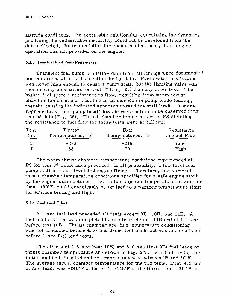
AEDC-TR-67-86
altitude conditions. An acceptable relationship correlating the dynamics producing the undesirable instability could not be developed from the data collected. Instrumentation for such transient analysis of engine operation was not provided on the engine.
5.2.5 Transient Fuel Pump Performance
Transient fuel pump head/flow data from all firings were documented and compared with stall inception design data. Fuel system resistance was never high enough to cause a pump stall, but the limiting value was more nearly approached on test 07 (Fig. 26) than any other test. The higher fuel system resistance to flow, resulting from warm thrust chamber temperature, resulted in an increase in pump blade loading, thereby causing the indicated approach toward the stall limit. A more representative fuel pump head/flow characteristic can be observed from test 05 data (Fig. 26). Thrust chamber temperatures at ES dictating the resistance to fuel flow for these tests were as follows:
Test Throat Exit . Resistance No. Temperatures, °F Temperatures, °F. to Fuel Flow
5 -233 -216 Low 7 -88 -70 High
The warm thrust chamber temperature conditions experienced at ES for test 07 would have produced, in all probability, a low level fuel pump stall in a sea-level J-2 engine firing. Therefore, the warmest thrust chamber temperature conditions specified for a safe engine start by the engine manufacturer (i. e., a fuel injector temperature no warmer than -150°F) could conceivably be revised to a warmer temperature limit for altitude testing and flight.
5.2.6 Fuel Lead Effects
A 1-sec fuel lead preceded all tests except 9B, 10B, and 11B. A fuel lead of 8 sec was completed before tests 9B and 11B and of 4. 5 sec before test 10B. Thrust chamber pre-fire temperature conditioning was not conducted before 4. 5~ and 8-sec fuel leads but was accomplished before 1-sec fuel lead tests.
The effects of 4. 5-sec (test 10B) and 8.0-sec (test 9B) fuel leads on thrust chamber temperature are shown in Fig. 27a. For both tests, the initial ambient thrust chamber temperature was between 25 and 50°F. The average thrust chamber temperature for the two tests, after 4. 5 sec of fuel lead, was -240°F at the exit, -118°F at the throat, and -211ÖF at
32

AEDC-TR-67-86
the fuel injector. After completion of the 8-sec fuel lead, the exit tem- perature was -296°F, the throat temperature was -245°F, and the fuel injector temperature was -420°F.
The fuel lead more effectively chills the thrust chamber at altitude than at sea-level pressures. The major differences observed at alti- tude conditions were (1) a lower backpressure or resistance to fuel flow, (2) sonic flow through the injector and throat, and (3) less heat transfer to the thrust chamber at altitude (at sea level, additional heat is added by a water-cooled thrust chamber diffuser and recirculation of hot gas inside the thrust chamber). Sea-level acceptance and AEDC altitude data indicate fuel injector temperatures of -165 and -420°F, respec- tively, after a fuel lead of approximately 8 sec (Fig. 27a). The fuel injector temperature before the fuel lead at sea level was 42°F.
An indication of the fuel system resistance drop as a function of temperature drop can be obtained from Fig. 27b (presented to indicate trends only). Note that after approximately 3. 0 sec, the fuel flow exhibits an increasing trend as the pressure differential decreases.
Slight thrust chamber temperature drops were noted after 1-sec fuel leads with the prechilled thrust chamber. Average temperature drops were 70°F at the exit and 25°F at the fuel injector.
5-2.7 Engine Shutdown Transient
Selected shutdown transient traces of typical engine valve and pressure parameters, obtained from high response oscillograph data, are presented in Fig. 28. Valve operating times at shutdown for all firings are depicted in Table X. Valve operating times were within specified limits in all cases. Engine shutdown transients were con- sistent and satisfactory in all cases, and a detailed transient discussion is omitted.
5.3 PERFORMANCE
Performance data were calculated from test measurements utilizing the PAST 640 computer program, a standard J-2 engine performance program developed and programmed by the engine manufacturer. This program calculates the engine and engine component performance based on (1) measured data or "site" and (2) measured data normalized to standard pump inlet engine ambient vacuum conditions. The required program constants, which included engine dimensional measurements, engine flowmeter calibration constants, pump head/flow constants, pump
33

AEOC-TR-67-86
efficiency constants, and thrust coefficient curve fit constants, were provided by the engine manufacturer. Engine test measurements re- quired by the performance program are itemized in Table XI. These measurements were obtained from the digital data acquisition system by averaging the 40 data samples obtained in the 1-sec time intervals of interest for each measured parameter required for the program. Fuel and oxidizer engine flowmeter cyclic output data were manually reduced from oscillograph.
Selected engine performance data computed for site conditions are presented in Table VI. The short duration of the engine firings during these tests limits the utility of the performance data. The original program plan was to conduct a 60-sec engine firing to permit attain- ment of engine thermal equilibrium for valid comparison of AEDC and acceptance test results. However, a 60-sec engine firing was not accomplished on the tests reported herein. Engine firing durations ranged from 5 to 30 sec for tests with an engine O/F ratio of 5. 0. A 40-sec duration firing was conducted with a 5. 5 engine O/F ratio.
The basic engine performance at AEDC is depicted in Fig. 29. It is observed that the thrust chamber fuel and oxidizer flow rates were slightly lower than nominal; however, the gas generator fuel and oxidizer flow rates were below the minimum requirements. The thrust chamber and gas generator propellant flow rates during these tests compared closely but were consistently lower than those values re- corded during engine acceptance tests. The curves classifying the flows as maximum, nominal, or minimum represent a block of J-2 engines (Ref. 2).
Factors limiting the confidence level in the engine performance data presented are (1) engine thrust was not measured but was calcu- lated from a chamber pressure relationship established during accept- ance tests, and (2) redundant propellant flowmeters were not used.
The S-1VB battleship stage performance was consistent and satis- factory for each test. Performance data for selected stage parameters are summarized in Table VII.
5.4 PROPELLANT DRY DUCT/PUMP INLET CONDITIONING
Three tests, not involving an engine firing, were conducted to simulate and evaluate the planned method for temperature conditioning the hardware associated with the propellant low pressure ducts and turbopumps for the J-2 engine restart application during the
34

AEDC-TR.<57-8fi
Saturn V/Apollo flights. These tests, conducted during the 09, 10, and 11 test periods, involved chilldown of the said hardware, from an initially dry condition, using the stage propellant recirculation sys- tems with the propellant prevalves closed. The propellant recircula- tion systems circulate propellants (fuel at about 143 gpm, oxidizer at about 43 gpm) from the vehicle propellant tanks, through the propellant low pressure ducts and turbopumps, and back into the vehicle propellant tanks (Fig. 9). Two of the tests consisted of a 5-min recirculation period; the third test consisted of a 10-min recirculation period.
Results and conclusions drawn from these tests are as follows:
1. A 5-min recirculation period was inadequate to properly tem- perature condition the fuel low pressure duct and turbopump hardware. At the termination of the recirculation period — the opening of the propellant prevalves in preparation for engine restart — the fuel pump inlet conditions remained in the safe ES region for only approximately 3 sec before return- ing to saturation conditions. However, the oxidizer pump inlet conditions remained in the safe ES region for an indefinite time period.
2. The 10-min recirculation period, including cycling the pre- valves, provided an adequate means for temperature condi- tioning the hardware of both propellant low pressure ducts and turbopumps. With the opening of the prevalves at the conclu- sion of the recirculation period, the fuel and oxidizer pump inlet conditions remained well within the respective safe ES regions. An inadvertent procedural error, resulting in the prevalves being cycled opened for approximately 13 sec, was encountered 10 sec after the chilldown recirculation had been initiated. Momentary cycling of the prevalves in the initial phase of the chilldown has been concluded to be an useful event in the chilldown cycle.
3. Saturn IB flight data indicate the low pressure ducts and pumps are not void of propellants before restart. Therefore, the AEDC tests present "worse-case"-type chilldown results.
5.5 FUEL START TANK REPRESSURIZATION AND WARMUP
The H2 sources for start tank repressurization are provided by tapoffs at the fuel manifold inlet and the fuel injector (Fig. 15). Once the start tank is pressurized to a level equivalent to the injector pres- sure (approximately 5 sec after the STDV solenoid is energized), the
35

AEDC-TR-67-B6
r epressurization source is limited to the manifold inlet supply. The maximum start tank pressure attainable during a firing is limited by the fuel manifold inlet pressure and firing duration.
Fuel start tank repressurization data from five firings are shown in Fig. 30a; duration of the firings presented ranged from 5 to 40 sec. Start tank pressures at engine shutdown ranged from 746 psia after the 5-sec firing {test 9A) to 1056 psia after the 40-sec firing (test 11A). Respective temperatures at shutdown of the 5- and 40-sec firing were -223 and -262°F.
The fuel start tank must contain at least 2. 5 lbm <Fig. 30b) of GH2 to meet the minimum start tank energy requirements. The mass existing at shutdown for the firings was determined and indicated that a firing duration greater than 20 sec is necessary to provide the mini- mum mass required to meet the minimum restart start tank energy. After the 20-sec firing, the calculated mass was 2. 32 lbm, and after 30 sec, the mass was 2. 88 lbm.
After shutdown of a 40-sec firing, the start tank conditions warmed to the safe start region in approximately 7 min. Start tank conditions existing at 10-min increments up to 50 min after shutdown are shown in Fig. 30b. A temperature-sensitive relief valve kept conditions from exceeding structural limits of the start tank. From the warmup data presented, the relief valve was observed to become active at approxi- mately 1350 psia and -203°F.
Warmup data from the Saturn IB AS-203 flight are also shown in Fig. 30b. Conditions existing at engine cutoff and end of first, second, third, and fourth orbit are noted.
5.d THRUST CHAMBER TEMPERATURE CONDITIONING
Pre-fire temperature conditioning of the thrust chamber was neces- sary to meet the conditions established for ES following the boost-phase warmup during launch. During these tests, the boost-phase warmup was not simulated because of facility test cell purge requirements. Temperature conditioning was accomplished by circulating He through a facility LH2 heat exchanger to obtain cold He, which was supplied to engine customer connect and then circulated through the thrust chamber.
A method was developed early in the program that made it possible to obtain any desired customer connect temperature. With the capa- bility of prechilling to any desired temperatures, and the repeatability
36

AEDC-TR-67-S6
of short coast temperature rises, temperature requirements were met. Thrust chamber preconditioning data obtained during a typical test (test 10A) are presented in Fig. 31. The conditions existing 220 sec before STDV solenoid energized are shown; at this time, throat tem- peratures were constant at -250°F and exit temperature of -265°F. Predictable temperature changes caused by initiation of maximum cell inerting purges (of approximately 30 lbm/sec) and facility steam ejector operation made it possible to obtain desired values at ES. After terminating the prechill, exit thermocouples warmed to approximately -166"F and stabilized. Thrust chamber skin temperature at the throat warmed to approximately -177°F and was essentially stable. The throat temperature, as indicated by TTC-1P, exhibited a continual increase after termination of the prechill. At to - 60 sec, a rise occurred in the exit temperature. This rise was caused by s.ome secondary cell flow and does not represent typical warmup. The curve is extrapolated in this region to show the expected data.
SECTION VI
SUMMARY OF RESULTS
The results of the 14 tests of the J-2 rocket engine (in the Saturn S-IVB stage configuration) conducted at simulated pressure altitude conditions in Test Cell J-4 are summarized as follows:
1. Altitude testing of the J-2 engine revealed that start transient characteristics at AEDC were different from the engine acceptance tests and provided an important insight into the J-2 engine transient operation for the Saturn IB and Saturn V flights.
2. Tests at AEDC demonstrated that start characteristics are primarily a function of (a) thrust chamber temperature condi- tions at ES, (b) start energy delivered to the turbines, (c) MOV opening sequence, and (d) ambient pressure altitude conditions.
3. Transient GGOT were consistently higher than engine acceptance tests and resulted in a premature termination of one test. The higher transient temperatures were attributed to improved oxidizer quality to the gas generator and lower fuel system resistance at altitude conditions.
4. The GGOT exhibited two transient peaks. The initial peak was demonstrated to be a function of thrust chamber conditioning temperature and start tank energy. The second peak was
37
AEDC-TR-67-86
demonstrated to be a function of the MOV operating sequence. Additional testing is necessary to predict the effect of turbine hardware temperature on GGOT.
5. Combustion instability during engine ignition was observed for time durations ranging from 3 to 132 msec for ten of the engine firings and compared favorably with the instability recorded during the Saturn IB AS-201 through -203 flights.
6. Engine transient side forces measured at AEDC were signifi- cantly less than those recorded during sea-level engine acceptance tests and are well within acceptable limits.
7. Fuel leads at altitude conditions were much more efficient in thrust chamber chilldown than at sea level.
8. Shutdown transients were satisfactory, and all valve operating times were within limits,
9. A 10-min propellant recirculation period, including cycling the prevalves, provided an adequate means for temperature conditioning the hardware of both propellant low pressure ducts and turbopumps from an initially dry condition for safe engine restart.
10. Engine firing durations greater than 20 sec are required to recharge the start tank to the minimum mass level required for safe engine restart.
REFERENCES
1. Test Facilities Handbook, {6th Edition). "Large Rocket Facility, Vol. 3." Arnold Engineering Development Center, November 1966.
2. "J-2 Rocket Engine, Technical Manual Engine Data. " R-3825-1, August 1965.
3. Dubin, M., Sissenwine, N., and Wexler, H. "U. S. Standard Atmosphere, 1962." December 1962.
4. "Tables of Thermal Properties of Gases. " National Bureau of Standards Circular 564, November 1965.
38

AEDC-TR-67-8*
APPENDIXES
I. ILLUSTRATIONS II. TABLES
39

AEDC-TR-67-86
Payload in i -= I-» 13
Diam
rn 61
S-IVB Stage
81 S-I Stage
¥
I fflfc I
l-»2l Diara
201
Payload
61 S-IVB Stage
■21 Diam
82
S-I I Stage w
138
<: i
S~ "N
362
33 Diam
Saturn IB Saturn V
All Dimensions in Feet
Fig. 1 Saturn SIB and S-V Launch Vehicle
41

> m O n
a. Side View
Fig. 2 J-2 Engine, S/N 2052

AEDC-TR-67-86
Gimbal Block
Fuel Low Pressure Duct
Propellant Utilization iValve
b. Top View
Fig. 2 Concluded
43

> m
00
Fig. 3 Aerial View of Test Cell J-4

AEDC-TR.67-86
Forward Skirt Structure
H2 Tank
Retro-Rocket
J-2 Rocket Engine
He Spheres
Oxidizer Tank
Aft Interstage Structure
Photograph Supplied by Douglas Aircraft Company
Fig. 4 J-2 Engine and S-IVB Flight Stage Assembly
45

Oxldizer Inlet Duct-
Fuel Inlet Duct
Fuel Turbopump Start Tank —
&
Discharge Valve
Uain Fuel Valve-
Turbine Bypass Du
Oxldizer Turbine Dypass Valve
Oxldizer Turbo pimp
Start Tank
Oxldizer Inlet Duct
Pneumatic Control Package
Auxiliary Flight Instrumentation Package
Exhaust Manifold
Thrust Chamber
> m
o
--4
Heat Exchanger
Fuel Bleed Valve
High Pressure Fuel Duct
Electrical Control Package
Primary Flight Instrumentation Package
Fig. 5 Details of the J-2 Engine

AEDC-TR-67-86
Main Oxidizer Inlet
Upper Fuel Manifold
Gimbal Mounting Surface
Oxidizer Dome and Injector Assembly
Exhaust Manifold
Main Fuel Inlet
Manifold
Fig. 6 Details of the J-2 Engine Thrust Chamber
47

AEDC-TR-67-86
Fuel Sleeve
Augmented Spark Igniter Chamber
Instrumentation Port-
Fig. 7 Details of ihe J-2 Engine Injector
48

AEDC-TR-67-86
ASI Fuel Manifold-
Ignition mitor
Fig. 8 Details of the Augmented Spark Igniter
49

To FUPI Klart Stack Fuel Tank PressurizatIon
Fuel rill and -*■ Drain Line
o
Oxldizer Fill and Duap Line
m O n
EZIZ3Combustion Products
— m2 iiiiininir.H
L03
Fuel Reclrculation Valve
LHj Engine Blppd Valve
Fuel Turbopunp
Main Oxldizer Valve
Oxldizer Turbine Bypass Valve
Fig. 9 Schematic of the S-IVB Stage''J-2 Engine

AEDC-TR-67-86
Fig. 10 Cutaway Drawing of Test Cell J-4
51

Identification Number
Consumable Syjstera
Additional Capacity
Current Capacity
0 LILj 112,000 gal 112,000 gal
o LN2 84,000 gal 88,630 gal
© GN2 1,311,000 scf1" 1,720,000 s.cf1
o GIL, 420,000 scf1 420,000 scf1
o GHe2 401,000 scf1 401,000 scf1
0 Steam 450,000 lb in
1,350,000 lb 1 ' m
0 L02 20,000 gal
0 Water 1,750,000 gal
to
Standard cubic feet at 5000 psia
Steam Plant
> m
n
Fig. 11 Test Cell J-4 Consumable Storage Systems, Plan View
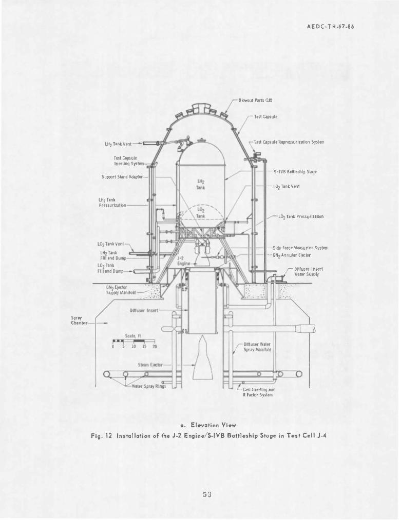
AEDC-TR-67-86
,— Blowout Ports (181
Test Capsule
LHj Tank Vent 1 H
Test Capsule Inertlng Systi
Support Stand Adapter-
LH2Tank Pressurl:atkjn
Tast Capsule Reprassurization System
- S-IVB Battleship Stage
■ • LOj Tank Vent
,-—LOjTank Pressurliation
Spray Chamber—
Slda-forceMeasuring System
GNj Annular Elector
— Diffuser Insert Water Supply
Cell Inerting and R Factor Svslen
a. Elevation View
Fig. 12 Installation of the J-2 Engine/S-IVB Battleship Stage in Test Cell J-4
53

AEDC-TR-67-86
b. Photograph
Fig. 12 Concluded
54

en 01
ä. Engine Pressure Top Locations
Fig. 13 Instrumentation Locations of the J-2 Engine
m a o
TO

"MT
> m
n -I
\"g?H , // ™,.
-"■■■—'VMWI
b. Engine Temperature, Flow, and Speed Instrumentation Locations
Fig. 13 Continued
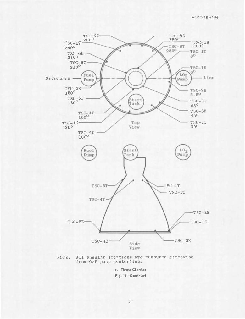
AEDC-TR.67-86
TSC-17 240°
TSC-6E 210° TSC-6T 210
TSC-7E 260°
Reference
TSC-5E 180 TSC-5T 180
TSC-16 120°
TSC-4E 100°
TSC-8E 280°
TSC-18 300°
TSC-3T 45° TSC-3E 45° TSC-15 60°
TSC-5E
TSC-4E
TSC-IT
TSC-3T
•TSC-2E
TSC-IE
TSC-3E
NOTE: All angular locations are measured clockwise from O/F pump centerline.
c. Thrust Chamber
Fig. 13 Continued
57

AEDC-TR-67-86
TFRfHJ PFI
PFRPO
Qf"S?P-
RPK—i
RPR-4
g ^^
FUEL CHLLDOWN RETURN LINE
NFRP-
FUEL TANK-LH2
FUEL TANK INSTRUMENTATION PROBE
RJELCHLLDOWN MOTOR-
i,- ^^C
<? -TFRT-2
&V TFRT-I \.CKOZEF TANK-ID 2
| LOz TANK INSTHUHENTAnOiV ' PROBE ->: t.
LO, FIX « OPAN UNE -NzH Ft3**1!-*
0
«a.
PFPI-U*3 TFPIH;
LOz CHULDOWN RETURN LINE
d. S-IVB Stage Instrumentation
Fig. 13 Concluded
58

2500
2000 -
1500 -
CO
pq
0) »H
3 ■M
Fi
e
-High Temperature Cutoff Limit
1000
500
-500 I 111 I
-Low ^Temperature Cutoff Limit (Time Approximate)
± _L 1 I
1.0 2.0 4.0 3.0
Time, sec
Fig. 14 Maximum and Minimum Allowable Limits for GG0T
5.0 6.0 n
09 O.


C5 CO
> m o n H 73
Fig. 17 Selected Engine Parameters for a Typical J-2 Transient

AEDC-TR-67-86
1500 r- 30,000
1250 - 25,000
1000
750
500
250
- 20,000
-£15.000
- 10.000
5,000
\ .x" Fuel Pump /
^ Turbine Speed-'
/■'
/
/ /
) X •
\ ,. ■*■"
^-
V :uel 5 "ank
tart 3ress k » jre
/ \ Oxidizer Pump \
/ V A
1 1 4 f
1000
800
a. too E
400
k. 2O0
a. Fuel and Oxidizer Pump Turbine Spinup
Valve Designation and Position
Time, MC
1 ! T —| Fuel Turbine
A B C 0 E F G H
STDVto ST0V,0
STOVic STOVic GGfpfio) GGtp(tol GGoptiol GGopifo)
a 158 0 315 0 535 0 804 0 522 0.5T5 0 621 0697
/G asCe nerat< :r Pn
ir c hamb SSW r\
A /, '-"~ —i.
|\ // ^^' ■ —
\ / '/
<-'' ■ Oxidizer Turülne Inlet Temperature
, /"
* /
WS /
> v- _> > /
' Oxidizer Turnine Inlet Pressure—7
A ; *S d1 )
- ' r Cr- ̂
1.0 2.0 3.0 Time, sec
Fig,
b. Fuel and Oxidizer Turbine Inlet Pressures and Temperatures
18 Start Transient Comparison of Selected Engine Parameters, Firing 10B
64
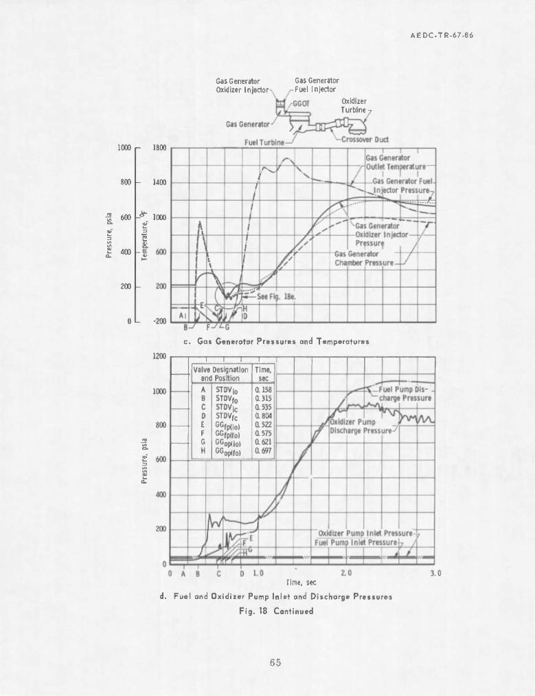
AEDC-TR-67-86
Gas Generator Oxidizer Injector
Gas Generator Fuel Injector
Oxidizer Turbine-
1000 r 1800
800 - 1400
•5 600
£ 400
200 -
0L
1000
c. Gas Generator Pressures and Temperatures
Time, sec
d. Fuel and Oxidixer Pump Inlet and Discharge Pressures
Fig. 18 Continued
65

AEDC-TR-67-86
300
200
100
1 1 1 Gas Generator
\ Oxldizer In- jector Pressure-7
\ Fuel Pump. Discharge Pressure^
s ^ V o ,:£•-*
C^- ---% > ^ ~Jr^ Gas Generator \
Chamber Pressure»
i\ A :.;i j V.
■A s: : \ 1 1 J \ -—' \/
V Gas Generator Fuel Injector
N ate: C atafo f this figur e were obta ned pressure
from a photographically recording galvanometer - type oscillograph.
0.5 0i6 tt7 Time, sec
e. Gas Generator Pressures and Temperatures
0.8
1000 I- W000
800
•5 600
£ 400 a.
200
8.000 -
6,000
3 4,000
2.000
Fuel Flow 7
P^"*"
* 1—' i • \
"~\
..-■--
ector
;hamber\ •ressure —
,10V Positk /' i
Fl Pr
iel In essui
/>
/' /
/
t
) • ,
> / ,' -v r
t
f j *rtS= Oxldi :er Fl
\ 3W
1 *4 ̂ ̂ 4
i—lOO
•75 j £ .2 S. = o -50
-25
Lo
O a»
1.0 2.0 3.0 Time, sec
Thrust Chamber Pressures, Propellent Flaws, and Main Oxidizer Valve Position
Fig. 18 Concluded
G6

AEDC-TR.67-86
700
600
500
400
300
200
100
Valve Designation Time sec and Position 06 07
//. A B C D E F G H
STDVio STDVfo STDVic STDVfc
GGfp(lo) GGfp(fo) GGop(lo) GGop(fo)
ai56 a 298 a 552 a 822 0.531
0.160 0.314 0.540 a 810 0.519 j V
0.582 0.573 a 627 0.624 Thrust Chamber
— ignition Time (Te 05 at 0.973 sec
•t i 0.694 a 694
* t
i inrf n7 si n 09
! 1 rcli\ A9 OxWizer Pump ^*s
//
1 ' !h A w ¥ f \
*<: $bi *!
\\ I1 i i
\ V— ̂ J
/
1 / / -^ -Fuel Pump Discharge Pressure
I IB
■'.-'
**
A ^-z* m i 1 ?
a. Fuel and Oxidizcr Pump Discharge Pressures
Time, sec
b. Gas Generator Fuel and Oxidizer Injector Pressures
Fig. 19 Effects of Fuel System Resistance on ES Transient Operation
67

AEDC-TR-67-86
24.000 r-
20.000 -
f 16,000
« 12,000
4.000
6000 r
5000
4000
3000
$ 8,000 - s 2000
1000
Valve Designation and Position
STDV|0
ST0V,o
STDVic ST0V,c
CGop(iol
Time sec
a 156
0.552 aszz a 53i as« a 62?
0.160 0.314 B MO a 810 1519 0.573 a m
aw a6«
5«^C
** &**
7. Ox id if er Pump Turbine Speed
I i S Generator Oxidiwr Injector— Gas Generator Fuel Injector
GGOT
c. Fuel and Oxidize' Pump Turbine Speeds
600
500
400
300
200
100
2000
Time, sec
d. Gas Generator Chamber Pressure and Outlet Temperatures
Fig. 19 Concluded
68

AEDC-TR-67-8Ö
24.000
20.000
16.000
torn
-& «m
I g 12.000
i 2 8.000
4.000
I -J 1000
2000
1000
a. Fuel and Oxldizer Pump Turbine Speeds
600
500
400
3
£ 300
1 a.
ZOO
100
><*
V
Watz Jlschi
srfu rge P
mp ressu
/$ re_ 4
., * J \y
P vi -S^
*\ 1 fi A \ J [^
^ X -Fu« -Disc
Pre
Pum harg« sure
i 1
A y
♦ "1 ffff 1 i
a.5 1.0 1.5 Time, see
b. Fuel and Oxidizer Pump Discharge Pressure
Fig. 20 Effects of Fuel Start Tank Energy on ES Transient Operation
69
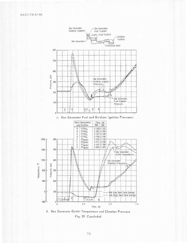
AEDC-TR-67-86
Gas Generator Oxldzer Injector
Gas Generator
-Gas Generator Fuel Injector
[ /•GGOTy^Fuel Turbine
-H
Crossover Duct
600
500
«r
& ^300
200
100
/ i i \ 1 i v\ I 1 j
w $ 1
V \ \ k Gas Generator //
^ V *
P ressu "A ,-^
'«mil \ <o , ( tejsr 4 tf • r -rt ̂
SVW/W" ~~^-Ges Generator Fuel Injector
1 i Pressure
A 1 /i ' ff,F «f 1
c. Gos Generotor Fuel and Oxidiier Ignition Pressures
2000r
1600
1200 -
1 S. I
Time, sec
Gas Generator Outlet Temperature and Chomber Pressure
Fig. 20 Concluded
70

0> >
iH et > U -H tU (A N a
■r-l •o - -r-l ,"■■
O 3 O*
C h •rH O
o U) rH O 3
O ^
<-i s a
-H o
c 0> r-l
dl c «H O «H -H ■H +J Q t.
0 ai & u o ra £ en ^- 0)
300
250
200
150
100
50
0
1.181 .o*^ & A Opened
* Position
Closed Position
Main Oxidizer Valve
Z -Time Referenced to t
Sym Test Nvunber
A 05 Q 06 O 07 D 08 O 09A u 10A u 10B 0 11A o 11B
0.5 0.6 0.7 0.8 0.9 1.0 1,1 1.2 1.3
Main Oxidizer Valve Second-Stage Initial Opening Time, sec
Fig. 21 Hydraulic Torque Effects on MOV Second-Stage Initial Opening Time
1.4 > m o n
o.
CD

-J
a M 3 F*4 4J0 d fa ■ <D s™%
UF- S <l c ^> H
Ü +J A c C — a +J 3 i-i Ü ri
■H u 4J o ■H +J S IB M M 0) fa c 1) u +» O VH
a !Tt cd e rt 3
E > •H rH c \A ■H
•H S +J C Ifl a s f- c <U ■H
*H ■(S 4H ■n Ü P «
<D <U (X fa 3 -0
+J B as O fa u a> 1) aw s 0 H
350 ^
300
250
200
o n
73
150
100
0.5 0.6 0.7 0.8 0.9 1.0 1.1 1.2 1.3
Main Oxidizer Valve Second-Stage Initial Opening Time, sec
Fig. 22 Effects of MOV Second-Stage Opening Time on GG0T Second Peak

AEDC-TR-67-86
2500
2000
1500
J*<
a k i)
e u
1000
500
"A \ V
-500 1.0
Gas Generator Outlet —• Temperature, Firing 11B (Automatic Shut- \ down Occurred at 1.378 sec)—*
1 I 2.0 3.0
Time, sec
4.0 5.0
Fig. 23 GGOT, Start Transient, Firing 11B
73

800
600
400
200
0
-200
-400
-600
-BOO
Engine Yaw Force aest 10B)
" p J" ̂ Vr r\
1 «LJ
1 l_
m
o I
-I
VI
600
400
200
-2D0
-400
-600
-800
-1000
1 Engine Pitch Force (Test LOB)
J ^jt r> "
'■ ^n? ^^^^
-4 -2 0 2 4 6 8 10 12 L4 16 18 20 22 24 26 28 30 32 34
Time, sec
Fig, 24 Engine Side-Force Data

01
300
■ (No Instability)
* 200 m ft
u 3 [0 to
Test 06
0 L—1 1 I I 1 ■ '
Test 10A
r*-25 msec
J l 1 I I I I I 1—I 1_—J—I 1 I L
Test 05
67 jnsec-H H"~
Test 04
-H 132 K 1 msec '
J I L
Engine Shutdown
-l_L 0.8 0.9 1.0 1.1 1.20.8 0.9 1.0 1.1 1.20.8 0.9 1.0 1.1 1.20.8 0.9 1.0 1.1 1.2
Time, sec
Fig. 25 Thrust Chamber Pressure Fluctuations during the ES Transient m D n -1 !0
4>
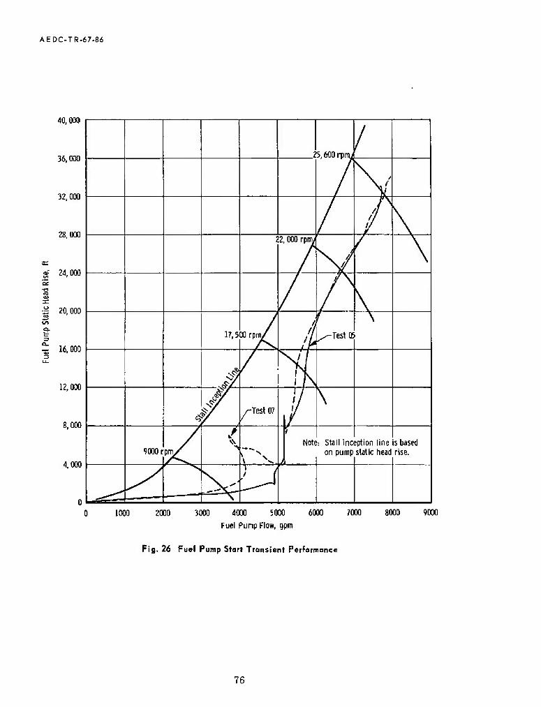
AEDC-TR-67-ßö
40,000
36,000
32,000
28,000
000
000
000
12,000
8,000
4.000
0> 24, 0£
18 a» 3= o 20, LO a. fc 3 n "äj 16,
25. MO roiTii
V/
// ff
\ 2 2,000 rpmi
\
17,5 Mrpm/ //
1 JF /-Test 05
\
•$ - <£/!
3 /-Test 07
//
90001 pny^
/ •> rx
Nott ': Stall ine on pump
option line static head
sbased rise.
/ (
1000 2000 3000 4000 5000 6000
Fuel Pump Flow, 9pm
7000 8000 9000
Fig, 26 Fuel Pump Start Transient Performance
76

AEDC-TR-67-86
1200
1000
§800
3600 -
400 -
200
Fuel Injector Temperatur«
0 L -500
1000
800
£600 cn
g u.
1400 u.
200
Zero time Is the beginning ol fuel lead (engine start).
I L
-Thrust Chamber \Throat Temperature
-Thrust Chamber- Exit Temperature
-Thrust Chamber Exit Temperature. Test 96
Fuel Injector —Temperature, Test!
I I * Note: Test 623-004 pre-luel lead
Injector temperature was 42°F. I I I
o. Temperature and Fuel Flow Trends
4. 0 5. 0 Time, sec
b. Fuel System Pressure Differentials and Fuel Flaw Trends
Fig. 27 Fuel Lead Effects
77

CO
m D n
CO
Fig- 28 Typical J-2 Engine Shutdown Transient

AEDC-TR-67.86
85
BO -
~E 75
■B
5 o "- 70
65
60
„Full Closed
I _l U
Sym Test Number Time Interval, sec
o 07 19.5 A 08 19.5 D 10B 29.5 O 11A 39.5 o 623-002 60 <Q 623-002 89.8
Maximum
Nominal
Minimum
i i I
I Full Opened
J I L
500
460
M 420 E
* 380 o
I 340 o
300
260
Full Closed
' I J_ . _L _
Maximum
Nominal
Minimum
Full Opened
I I l l
tt 2 0.4 0.6 a 8 1.0
Propellant Utilization Valve Position, Voltage Ratio
1.2
o. Thrust Chamber Flow Rote.versus PU Valve Position
Fig. 29 Thrust Chamber and Gas Generator Propellant Flow Rates versus PU Volvo Position
7.9

AEDC-TR-67-BÖ
4.6
4.2
£ 3.8
a:
1 3.4
3.0
2.6
I Full Opened
Sym" Test Number Time Interval, sec
o 07 19.5 A 08 19.5 □ 108 29.5 o 11A 39.5 o 623-002 60.0 ^ 623-002 89.8
Maximum
Full Closed
i i I I . I i i i
4.0
3.6 -
E £ 3.2
5.
2.8 -
2.4
2.0
^v.
<5->^_
- ^\xi "•v. ^-Maximum
- o\
- "X. ^Nominal
- 1 Full Opened
" 1 i I l I 1 1 1 1
^sMinimun Full Closed
1 i i i i
0 0.2 0.4 0.6 0.8 1.0
Propellant Utilization Valve Position, Voltage Ratio
b. Gas Generator Flow Rate versus PU Valve Position
Fig. 29 Concluded
1.2
80

CO
-40
-BO
-120
-IN)
5 -ZOO
-240
-230
-320
-360
1 1 1 Syn Test Number Firing Duration, sac
o 06 OB
10 20
a DM 5 Ö in 30 X ILA *
T6S109A , - Test 06 Shutdown
| 1 3
^
Shutdawn-j / Ml 06 —1
L^ d ifiutdown Safe
■"""^Ss i^^^^zl -"- *^»^_ -Test 1IA Engine Slarl , Region /
r^ ^
Liact >nfi ^hntHniim
/
•Z&^J
100 200 300 4M 50O 600 700 800 Pressure, psia
900 1000 1100 1200 D00 1400 1500
a. Start Tank Repressuri ration
Fig. 30 Fuel Start Tank Repressurization and Wormup Data
> m D n
Öl

AEDC-TR-67-86
-80
-120
-160
-200
+J
o E H
-240
-280
-320
-360 1000 1100 1200 1300 1400
Pressure, psia
b. Shirt Tank Warmup Data
Fig. 30 Concluded
1500 1600
82

fe
01 U
Q. g
-140
-160
-180
-200
-220
-240
-260
-280 -220 -200 -180 -160 -140 -120 -100 -80
Time, sec
Fig. 31 Pre-Fire Warmup Trends of the J-2 Engine Thrust Chamber
-60 -40 -20 o n
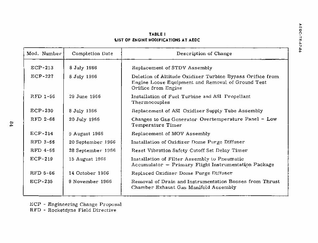
TABLE I U5T OF ENGINE MODIFICATIONS AT AEDC
Mod. Number Completion Date Description of Change
ECP-213 8 July 1966 Replacement of STDV Assembly
ECP-227 8 July 1966 Deletion of Altitude Oxidizer Turbine Bypass Orifice from Engine Loose Equipment and Removal of Ground Test Orifice from Engine
RFD 1-66 29 June 1966 Installation of Fuel Turbine and ASI Propellant Thermocouples
ECP-230 8 July 1966 Replacement of ASI Oxidizer Supply Tube Assembly
RFD 2-66 20 July 1966 Changes to Gas Generator Overtemperature Panel - Low Temperature Timer
ECP-214 9 August 1966 Replacement of MOV Assembly
RFD 3-66 20 September 19G6 Installation of Oxidizer Dome Purge Diffuser
RFD 4-66 28 September 1966 Reset Vibration Safety Cutoff Set Delay Timer
ECP-219 15 August 1966 Installation of Filter Assembly to Pneumatic Accumulator — Primary Flight Instrumentation Package
RFD 5-66 14 October 1966 Replaced Oxidizer Dome Purge Diffuser
ECP-235 9 November 1966 Removal of Drain and Instrumentation Bosses from Thrust Chamber Exhaust Gas Manifold Assembly
m O O I
ECP - Engineering Change Proposal RFD - Rocketdyne Field Directive
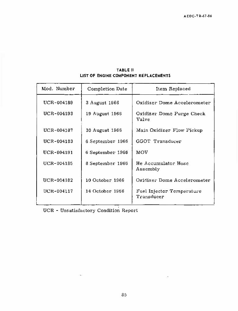
AEDC-TR-67-B6
TABLE II LIST OF ENGINE COMPONENT REPLACEMENTS
Mod. Number Completion Date Item Replaced
UCR-004189 3 August 1966 Oxidizer Dome Accelerometer
UCR-004193 19 August 1966 Oxidizer Dome Purge Check Valve
UCR-004187 30 August 1966 Main Oxidizer Flow Pickup
UCR-004183 6 September 1966 GGOT Transducer
UCR-004191 6 September 1966 MOV
UCR-004185 8 September 1966 He Accumulator Hose Assembly
UCR-004182 10 October 1966 Oxidizer Dome Accelerometer
UCR-004117 14 October 1966 Fuel Injector Temperature Transducer
UCR - Unsatisfactory Condition Report
85

TABLE IM INSTRUMENTATION DESIGNATION OF SELECTED PARAMETERS
> m o n
00 05
Item No.
Parameter AEDC Code
NASA Code
Tap No.
Range bo 3 <
o >f-l
Osc
illo
- gr
aph P. u
Temperatures °F
1 Fuel Pump Inlet TFPI-1 CS37 -425 to -415 X
2 Fuel Pump Inlet TFPI-2 C658 -425 to -400 X X X
3 Oxidizer Pump Inlet TOPI-1 C638 -300 to -275 X
4 Oxidizer Pump Inlet TOPI-2 C659 -310 to -270 X X X
5 Fuel Pump Discharge TFPD-1P C134 PFT1 -425 to -400 X X X
6 Fuel Pump Discharge TFPD-2 C644 PFT1 -425 to -400 X
7 Oxidizer Pump Discharge TOPD-1P C133 POT 3 -300 to -250 X X X
8 Oxidizer Pump Discharge TOPD-2 C648 POT 3 -300 to -250 X
0 Main Fuel Injection TFJ-1P C200 CFT2 -425 to +100 X X
10 ASI Fuel Injection TFASIJ IFT1 -425 to +100 X X
11 ASI Oxidizer Injection TOAS1J IOT1 -300 to ^100 X X
12 Fuel Turbine Inlet TFTI-1P C001 TGT1 0 to 1800 X X
13 GG Overtempe r ature TGGO-1A C755 GGT1 0 to 2000 X X
14 Fuel Turbine Outlet TFTO C654 TGT2 0 to 1H00 X
15 Oxidizer Turbine Inlet TOTI-1P C002 TGT3 0 to 1200 X
16 Oxidizer Turbine Outlet TOTO-IP C215 TGT4 0 to 1000 X
17 Fuel Start Tank TFST-1P C00G TFT1 -350 to 4 100 X
■vl
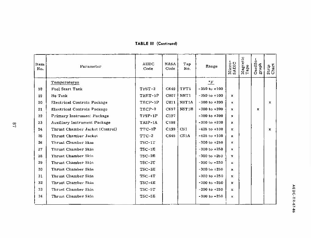
TABLE lit (Continued)
oo
Item No.
Parameter AEDC Code
NASA Code
Tap No.
Range ÖS Si W M
agnet
ic
Tap
e
Osc
illo
- g
rap
h
P. u
Temperatures "F
18 Fuel Start Tank TFST-2 C649 TFT1 -350 to +100
19 He Tank THET-lP C007 NNT1 -350 to +100 X
20 Electrical Controls Package TECP-1P con NST1A -300 to +200 X X
21 Electrical Controls Package TECP-2 C657 NST1B -300 to +200 X X
22 Primary Instrument Package TPIP-1P C197 -300 to +200 X
23 Auxiliary Instrument Package TAIP-1A C198 -300 to +200 X
24 Thrust Chamber Jacket (Control) TTC-1P C199 CS1 -425 to +100 X X
25 Thrust Chamber Jacket TTC-2 C645 CS1A -425 to +100 X
26 Thrust Chamber Skin TSC-IT -300 to +250 X
27 Thrust Chamber Skin TSC-IE -300 to +250 X
28 Thrust Chamber Skin TSC-2E -300 to +250 X
29 Thrust Chamber Skin TSC-3T -300 to +250 X
30 Thrust Chamber Skin TSC-3E -300 to +250 X
31 Thrust Chamber Skin TSC-4T -300 to +250 X
32 Thrust Chamber Skin TSC-4E -300 to +250 X
33 Thrust Chamber Skin TSC-5T -300 to +250 X
34 Thrust Chamber Skin TSC-5E -300 to +250 X
> m D n
»

TABLE III (Continued)
>
v n
oo CO
Item No.
Parameter AEDC Code
NASA Code
Tap No.
Range ■■-, <<
Mag
net
ic
Tap
e
Osc
illo
- gra
ph
a. u
55 o
Temperatures !£ 35 Thi ust Chamber Skin TSC-6T -300 to +250 X
36 Thrust Chamber Skin TSC-6E -300 to +250 X
37 Thrust Chamber Skin TSC-7E -300 to +250 X X
38 Thrust Chamber Skin TSC-8T -300 to +250 X X
39 Thrust Chamber Skin TSC-8E -300 to +250 X
40 Oxidizer Recirculation Pump Return Lmc TORPR C150 -300 to -140 X
41 Fuel Recirculation Pump Return Line TFRPR C161 -425 to -250 X
42 Oxidizer Recirculation Pump Outlet TORPO C163 -300 to -250 X
43 Fuel Recirculation Pump Outlet TFRPO C157 -425 to -410 X
44 Fuel Tank TFRT-1 C50G -425 to -410 X
45 Fuel Tank TFRT-2 C507 -425 to -410 X
46 Oxidizer Tank TORT-1 C527 -300 to -287 X
47 Oxidizer Tank
Pressures
TORT-2 C528 -300 to -287
psia
X
48 Fuel Pump Inlet PFPI-1 D503 100 X
49 Fuel Pump Inlet PFPI-2 D536 200 X X X X
50 Oxidizer Pump Inlet POPI-1 0504 100 X

TABLE III (Continued)
ec
Itera No.
Parameter AF.DC Cade
NASA Code
Tap No.
Range i O
ö < Si w
1 Mag
net
ic
Tap
e
Osc
illo
- gra
ph
' S
trip
C
har
t
Pressures psia
51 Oxidizer Pump Inlet POPI-2 D537 200 X X X X
52 Fuel Pump Discharge PFPD-1P D008 PF3 1500 X
53 Fuel Pump Discharge PFPD-2 D516 PF2 1500 X X X
54 Oxidizer Pump Discharge POPD-1P D009 P03 1500 X
55 Oxidizer Pump Discharge POPD-2 D522 P02 1500 X X X
56 Main Fuel Injection PFJ-1A D004 CF2 1000 X X
57 Main Fuel Injection PFJ-2 D518 CF2A 1000 X
58 Main Oxidizer Injection POJ-1A D005 C03 1000 X
59 Main Oxidizer Injection POJ-2 C03A 1000 X X X
60 Thrust Chamber PC-IP D001 CGI 1000 X X
61 Thrust Chamber PC-2 D544 CGI 1000 X X
62 Thrust Chamber PC-3 D524 CGI A 1000 X X
63 ASI Chamber PCAS1 D514 1G1 1000 X X
64 Fuel Jacket Inlet Manifold PFMI CF1 2000 X
65 GG Fuel Injection PFJGG-1A D011 GF4 1000 X
6R GG Fuel Injection PFJGG-2 D527 GF4 1000 X X
67 GG Oxidizer Injection POJGG-1A D012 G05 1000 X X
> m o n
<7>

TABLE IM (Continued)
> m o o
CD O
Item No.
Parameter AEDC Code
NASA Code
Tap No.
Range o O o P
Mag
net
ic
Tap
e
Osc
illo
- [
gra
ph
at to O
Pressures psia,
68 GG Oxidizer Injection POJGG-2 D529 G05 1000 X
69 GG Chamber PCGG-1P D010 GG1 1000 X X
70 GG Chamber PCGG-2 D530 GG1A 1000 X
71 Fuel Turbine Outlet PFTO TG2 200 X
72 Oxidizer Turbine; InLet POTI-1A D007 TG3 200 X
73 Oxidizer Turbine Outlet POTO-1A D086 TG4 100 X
74 Oxidizer Turbine Outlet POTO-2 D533 TG4 100 X
75 Fuel Start Tank PFST-1P D017 TF1 1500 X X
70 Fuel Start Tank PFST-2 D525 1500
77 He Tank PHET-1P D019 NN1 3500 X X
78 He Tank PHET-2 D534 NN1 3500
79 Fuel Recirculation Pump Return Line PFRPR D062 50 X
80 Oxidizer Recirculation Pump Return Line PORPR D061 100 X
81 Fuel Recirculation Pump Outlet PFRPO D060 60 X
82 Oxidizer Recirculation Pump Outlet PORPO D059 115 X
83 Fuel Tank Ullage PFUT D539 100 X
84 Oxidizer Tank Ullage POUT D540 100 X
^1

TABLE III (Continued)
CD
Item No.
Parameter AEDC Code
NASA Code
Tap No.
Range ö O ü Q
*3 w
u •w-t +-> Ü
Osc
illo
- gr
aph at
■r1 rt
Flows gpm
85 Fuel Fiowmeter QF-1A F002 PFF 9000 x X
86 Fuel Fiowmeter QF-2 F507 PFFA 9000 X X X X
87 Oxidizer Flawmetor QO-1A F0U1 POF 3000 X X
88 Oxidizer Fiowmeter QO-2 F506 POFA 3000 X X X X
89 Fuel Recirculation Fiowmeter QFRP F0Q5 160 X
90 Oxidizer Recirculation Fiowmeter
Speeds
QORP F004 50
rpm
X
91 Fuel Pump Speed, rpm NFP-1P T002 PFV 30, 000 X X X
92 Oxidizer Pump Speed, rpm NOP-1P T001 POV 12, 000 X X X
93 Fuel Chilldown Motor Speed, rpm NFRP T501 15, 000 X
94 Oxidizer Chilldown Motor Speed, rpm
Vibrations
NORP T500 15, 000
g
X
95 Thruat Chamber Dome UTCD-1 F706 ±150 g X X
96 Thrust Chamber Dome UTCD-2 E707 ■ ±150 g X X
97 Fuel Pump Radial 90 deg UFPR E556 ±200 g X
98 Oxidizer Pump Radial 90 deg UOPR E555 ±200 g X
> m o n
JO
ö< -j
CD
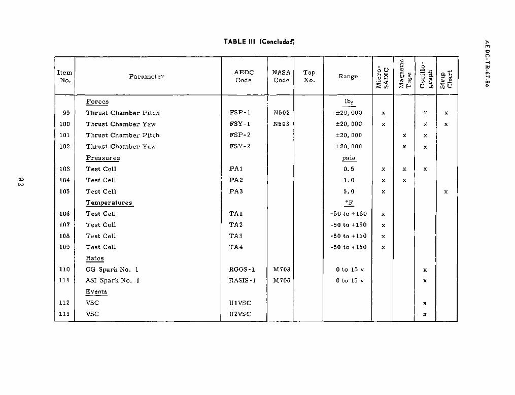
TABLE III (Concluded)
Item No.
Parameter AEDC Code
NASA Code
Tap No.
Range oU ÖS A en
*-» HI
as a. a «
Osc
illo
- gr
aph a. t.
r1 it
35 u
Forces lbf
99 Thrust Chamber Pitch FSP-1 N502 ±20, 000 X X X
100 Thrust Chamber Yaw FSY-1 N503 ±20, 000 X X X
101 Thrust Chamber Pitch FSP-2 ±20, 000 X X
102 Thrust Chamber Yaw
Pressures
FSY-2 ±20, 000
psia
X X
103 Test Cell PAl 0.5 X X X
104 Test Cell PA 2 1.0 X X
105 Test Cell
Temperatures
PA 3 5.0
'F
X X
106 Test Cell TA1 -50 to +130 X
107 Test Cell TA2 -50 to +150 X
108 Test Cell TA3 -50 to +150 X
109 Test Cell
Rates
TA4 -50 to +150 X
110 GG Spark No. 1 RGGS-1 M708 0 to 15 v X
111 ASI Spark No. 1
Events
RASIS-1 M706 0 to 15 v X
112 VSC U1VSC X
113 VSC U2VSC X
a n
73
03

TABLE IV ENGINE PURGE SEQUENCE AT AEDC
CO
Turbopump and GCI (Purge Manifold System)
Oxidizcr Dome and CC Oxldlser Injector (Engine Pneumatic System)
Oxidizer Dome (Facility Line to Instrumentation Port COA3)
Oxidizer Turbopump Intermediate Seal Cavity (Engine Pneumatic System)
Thrust Chamber Jacket (Purge and Preconditioning through Customer Connect Line)
He, 82 - 12S psia 50 - 200*F at Customer Connect Panel, B aufm Nominal
He, 400 * 25 pslf at Engine Pneumatic Package Outlet. 50 to 200T at lie Fill Customer Connect, 230 Bcfm Nominal
N2, -111(1 - 450 psig. 100 - 200"F at Facility Check Valve, 200 BcTm Minimum
He, 400 ± 23 psig ul Engine Pneumatic Package Outlet, Engine Ambient Temperature, 2B00 - V000 «elm
He, 40 - «0 psig, SO - 201TK at Customer Connect Panel, 60 scfm Nominal
He, 12 • 14 psig B0 - 200"F at Customer Connect Panel, 10 scfm Nnmtnal
He, 1UU0 neig at Customer Connect Panel, 10 - 20 Ibm/min
A
wfa
vk
M/////////////A
Ift min IV m
Any Time Walvr Is On
jif utnutu'fU>*"L' * 'Except when High Purge On'
{ 1-3 min-"-J
11
if*
- 2-min Minimum —* Fuel | Following Tank \
I Preaaurlzalion* R
1-3 min -^ h»
rl see (Supplied hy—T Engine He Tank * during Start snd Cutoff Transient
V/////////////M zr
mm
Duration of Hold
■Main-Stage Operation- (Supplied by Engine Ho T»nk) Twm/k
11ii in i > i j ; } i )» i i 4i Duration or Hold'.ii !/11 ii 11 iii t i 1i /11
10 min
«Limitation imposed.
(When water Is off, purge occurs only for 15 roin after oxidizer drop.
t Except when high purge on.
> m O n » H 73
CO

TABLE V SUMMARY OF TEST CONDITIONS AND RESULTS
> m O n
to
Test Ninnhnr 02 03 04 09 00 07 0B OSA onn KIA KIB I1A
11-16-66
1 IB 11C
Test Date B-27-0C !l-2-(i(i B-14-H« H-Z4-IM a-30-b'ti 10-7-BS 10-18-66 10 27-66 10-27-66 11-4-66 11-4-55 ll-lti-66 u-ia-66
Pressure Altitude at KS, ft ns, son 77. 300 «7. 200 53.300 59.000 73,000 75, 3011 fi2, 4 00 112, 300 105, 700 10D, 200 lOt1. 000 104.000 108,700
Firing Duration, «ec 1. luB 1.032 1.0B2 10.075 1(1,(170 20.070 20. 078 5.068 0.454 5.070 30. Ott 40.070 1.378 0.071
Knel Pump Inlet Conditions al IS
Pressure, pain 37.8 37.2 15, 2 JS.O 30.2 30. a 30.4 33. 1 34.0 35. 1 35.8 3S.4 36.0 40.3
Temperature, "F -■120. 2 -«19.U -420. 1 -4111. H -420,5 -416.8 -420. 1 •420, 9 -421.3 -420.9 -421.2 -420. 2 -420.9 -41U. 4
OxlriiTcr Hump Inlet Conditions al ES
Pressure, puia •10.4 39.9 40.1 40.3 40. 1 40. li 41). 1 41.2 SB, n 10.7 38.5 H'J, 2
-295, 1
40.6 39.5
Tempern
PresBure
turp, "K 295. 1 -2II5.G -295. 1 -235,3 -2BÄ.n -205.3 2U5.0 -28*. i ■289.0 -2B6.0 -209.2 -2119.7 -289.6
.Start rnnk Conditions at ES
. pa ia 1, 241 1. 24B 1. 2K5 1, 321 1. 332 1.323 1, 314 1, 2R4 1, 350 1.353 1, 3(12 1, .1(12 1, 302 N/A
Temperature, *F -244 -2)10 251 -iao -IBS -204 - 173 -187 -190 -200 -211 -198 -205 N/A
He Tajik Cumliliona at E5
Pressure, pHla 3, OOfi 3, (112 a, osa
-281
3, 005
-1HU
3, 016 3. 024 3.00B 3, 033 3, 143 3, 213 3.000 3, U1III 2, SHIO N/A
Temperature, *!• -244 -260 -195 •204 -173 -188 -190 -200 -211 -190 -205 N/A
Tlirum rhamber Temperature Cunditions at ES, *F
Throat -28B -252 -23» -234 -171 -00 -22C -217
-ISO
♦ 47 -213 + 37 - 1711 -171 + 47
Exit -167 -192 -211 -206 -175 -7« -'in -I3(i us 124 -110 + 37 34
Fuel Lead Time, sec 1.032 1.051 1.031 1.031 1.050 1 . 078 1, 048 1. OJfi 7.937 1.037 4.504 1.072 B. 12ft 3.243
Fui*l in Engine Time, in n 104 61 ill 108 11H 102 SO 57 84 71 117 Uli 94 10
Oxidlzar in Engine Tlnu , mifl 104 61 Bl 105 LIB 102 GO 67 84 71 117 B 6 94 10
Prnpellant Reelrculation Time, mln 3! 11 11 5B 10 12 111 12 11 II 5 10 10 10
ran Duration Time, msec 30 12 132 67 0 30 15 3 N/A 25 0
l.GUU
63 20 N/A
GG Tcmperalure initial Splkr 1, 700 2, 230 1. »B0 I.8S0 1.740 l,i:50 1,740 1,700 N/A 1,010 1,790 2, D0D N/A
Second Spike — --- 1,070 I,fi80 1, 480 I.R10 1, 730 N/A 1.870 1.660 1,730 2,150 N/A
Thruel Chamber Ignition, sec 1.034 0.997 0.979 0.973 1), 1)7(1 0.978 0.990 0.904 N/A 0. 962 0.973 0.856 0 937 N/A
MOV Initial Opening Tim«, «oc 1.012 1, 000 1 000 1.001 1.000 1. 110 1. I5U 1. 155 N/A 1.200 1.173 1.212 1, 290 N/A
Main-Suit;«- "OK" Signal, see N/A N/A N/A 1.044 l.lj4b 1.848 1. 720 1.C85 N/A 1.090 1.S23 l.«50 N/A N/A
SaO-psm fhnmher Pressure Attained, sec N/A N/A N/A 1. »19 1.517 1,951 1.860 1.910 N/A 1.BS7 1. 925 1.878 N/A rs/A

TABLE VI ENGINE SITE PERFORMANCE SUMMARY
CD en
Test Njtiibi'i 05 06 07 08 10B HA
FataSLio.o TüüD, aw lr. 1 9.B 9.5 19.5 18.5 »..1 10.5 29.5 0.5 10.5 29.5 30.5
Pressure, Attitude, ft 03.800 (iS, 300 N3, 300 80, 350 87, 000 100, 300 100, 300 88, D00 08, 500 97, 300 96,000 87,500
Overall Engine I'tfrTormancn
Thrust, Ihf Site IBO. ISO 111(1,(130 100,710 102,170 182.930 191, 120 182.800 192.220 217.850 220, 060 220,130 210,350
VuL'Uum 194.370 194,240 192, 320
424. 1
104,020 194.290 191.870 183.420 193. 010 218,650 220.010 221.020 220, 670
luipuL&e' il>m
Slle 420.4 418.4 424.2 422.0 41.1. 1 428. 6 424. 1 421.8 122.2 422.7 422.2
Vacuum 429.5 42C.3 427.7 428.3 425.0 424.7 430.2 427.2 423.1 423.8 424.4 424.8
Mixlure ftutm 4. QUO 4.B7B 4.84D 4.888 4.822 4.832 4.830 4.855 5.404 5. 482 5.51B 5.44H
Fuel Weight Flow, lbm/eec 71.1U 77.10 7G.92 76.83 77.20 77.48 77.12 77.42 HI), ns 80, 28 79.92 80,57
Clxiiib-cr Weigh« Flow. lhm/a»r J75. : 378.1 372.7 37G.0 379. a 374.28 372.5 375.8 435.8 440.9 440.8 438.9
Total Weight Flow, Lb^/sec 4*2. J 455. 0 449.6 453.0 457. 1 451.74 449.8 453.3 516.5 521.: 520.0 519.5
427. 9~
^7948 ~
Thruiil Chamber Performance
!%|KTI(IC Impulse, lbf-Bct/lbm 4as. 3 424. 1 430. 1 430.2 427.9 42U. 0 434.8 430.0 427.5 427.9 420.4
CharactarlMli Velocity, H/net: 8, 098 S, 038 8,071 8, 07» 8,015 8.015 8. 118 8, ii v; 7. »25 7,928 7,930
Thrust Coefficient
Site I.0H4 I.G9H 1.714 1.713 1.718 1.722 1.72.7 1,717 1.738 1. 738 1.736 1.732
Vacuum 1.730 1.7.111 1.7»» 1.730 1.730 1.729 1.730 1.730 1.742 1.743 1.743 1.713
Mulurc Ratio 5.045 S. 061 5.02« 5.073 5. 10D 5.015 5.013 5.038 5.613 5.704 5.730 5.658
KUPI Weight Flow, Ibm/scc 73, B0 74,25 73.55 73.55 73.80 74. 07 73.73 74.03 77.06 76.72 76.36 76.98
D.ldlifr VMjbt Flu*. Ibm/st 372.3 375.3 3G0. G 373.2 377.0 371.4 :i(ü). G 373.0 432.8 437.8 437.5 435.6
Total WHghl Hi», ll.n,/»eL- 448. 1 140.1 443.4 448. 7 450.8
B59. 2
445.5 413.4 447.0 509. 6
730.8
514. 3 513.9 512.6
Chamber Prpflsure, pnia 659.2 658.1 6S2. 0 B58.1 851.5 656.5 657.1 744.0 744. 3 743.2
Fuel Injector
Oxidier
Injector
Stagnation pressure, psi» 749. a 74 B. 4 V41, 1 748.4 748. 1 742.5 718. G 717.4 835. 4 842. 3 844.4 844.5
T
S
eLaperature, "I' -295.0 -2B2. 1 -20S.3 -2U5.0 -297.8
704.0
-288.5 -287.2 -2H7.5
796.8
-278.D -278.6 -278.3 -271.5
tarnation Presnure, psU 71)1.3 784.0 775.2 709. C 788.0 788.7 903.6 921.3 925. G 926.9
Fuel
lJump Perrormuiice
Inlet Hressure. paid 34.4 34.7 34.4 34. C 33.8 34.2 34.5 34.7 34.8 35.3 34.8 34.4
Density, lbm/rt* 4. 12 4.35 4.32 4.32 4.35 4.36 4.36 1.35 4.32 4.32 4.32
1. 192
4.32
1. 194 DUübar^e
Preftwurc, pr.ia 1.072 1.071 1.059 1.084 1. nun 1.0511 I. 065 1.088 1. IBS 1. 192
[i-uo.t>. Ibm/ft3 4.41 4,41 '1.41 4. 41 4.43 4,48 4,48 4.48 4. 45 4.44 4.41 4. 44
lUad, tt 33, 280 33, am 32, 880 33, 040 32, I! 70 32,n3e 32. R2CV 32.880 38, HOB 37, 000 37, 020 37,080
äppMl, rjjm 2ä, 860 25,403 25,220 25,210 25,570 an, :im 25, 3811 25, .750 28,710
so. is 20, 750 20, 760 26,710
Kugln How. lb„,lute 77.19 77.50 78.92 76.83 77. 2u 'It. 4b 77. 12 77.42 80.28 79.92 80.51
Volume FIDW, fipm S.OIO 7,980 7,886 7.B87 7. ati2 7, »HO 7,846 7,979 8,376 8.339 8. 303 8. 372
Efficienc V 0. 704 0. 584 0.711 0.711 0.702 0.733 0.733 0.732 0.732 0.730 0.729 0.728
n
o ->4

TABLE VI (Concluded)
CD
Tejt Number 05 IX!
V.b
31). 7
07 DO 1KB 11A
Data Slice Time, nee 9.5
40. i
B...
4«. n
19. 5 19 5 8 5 10.5 20.5 9, 5 19.5 20.5 | 39.5
OxMUer Pump Performaiiq»
Illlel Stagnation Prel&ure, pola :«. o :<H.M 39.5 39. 4 39.3 30.5 38. 7 38.4 i 38.8
»eiibltv. Ibm/rt-1 70. 95 70, IIS 7(1. 0 1 7u. 7o 7U. OH 09. 02 00. 81 Kti. 80 71, in 71.09 71.08 71. 05
DIBI hurgr äta^imtiDii PiMaure, psia 890. ir see. o 87B. Ü sar.. o 093.5 002.2 0N1. 2 Hll.l. 1) 1, U4I 1.1151 1.05 2
71.20
1.051
71.25 Dciially, 1.1,,,/rt-1 TO. as 70.87 70. 02 70.79 70.00 09.03 00. 01 as. oo 71. 31 71. 29
Hpad, fl 1.727 1.727 1.7U4 1,721 1,734 1, 730 1,757 1,701 2,024 2,04,7 2,047 2, D4J
Sltceil. rjim 7.705 7.703 7,741 7. 79G 7.819 7,011 7, BOO 7,075 8, 370 B,43f. 0,453 0,451
Wei^hl Flow, ltim/src 455.4 458.6 451.0 455.0 461.0 452.4 452. 1 455.0 443.4 4411. 5 440.4 446.5
Volume l'~U(w, l^l'in S. HS1 2,9011 i. 05U
(). "10
2. onn
o. «in
1. 911»
fl. Nil
3,908
0.K10
2.907 2.931 2. 71)0 2. 832 2.832 2.820
Efficiency 0.810 0.011 0.810 0.810 0.799 0,800 0.800 0. 79U
PL' Vnlvr l\>Hilii>n, (leg -0. 7 0.0 -11.» -n.it -0.7 -0. 7 0.7 -0.7 31.3 31.3 31.3 31.3
CG Performancft
Chamber Prcflaurr (Measured), pulj 5C2. 0 577.7 575.0 502. 5 500.0 577. 0 381. O 582.0 040. 2 05 3.4 053.3 050. 5
Muiure liatio U. 040 U. 852 U. 031» U. 050 0.054 O. 030 0.047 0 849 fl. 911 0.928 O. 030 0.92U
Fuel W»l|jht Flow. lbm/«ec 3. 3» 3. 35 3. 37 3. 30 3.40 3. 30 3. 30 3. 38
2.87
3 58
3.27
3.5 7
3. 31
3. 50 3. 58
Oxidlzer Weight Flow, lbm^se<. 2.07 2.05 2. 03 2. 0B 2.90 2.03 2.87 3. 31 3. 33
Tul«l Wcichl Fin». lhm/s¥. 6. 26 8.20 es. 21 Ü. 20 li. 30 6. 23 0.20 6.25 6.85 6.68 0.87 6.91
Fuel Turbine Performance
Welslil Hir», IM,,,,'»,'. «.36 B.20 0.21 6. 26 C. 30 0.23 0.26 6. 25 6.85 6.03 6.87 6.91
Inlrl SIUIIL l'rei*Hiirc* psia CHI. 1 n37. 1
1,022
535. 3
I, 02!>
541.« »45. 0 535. 4 541. 0 541.1 003. 7 linn. 7 000. 0 «11.8
Temperature*, •K 1. 14-1 1.04H 1, 1150 I, 024 1,1142 1,047 1, 152 1, lfld 1, 103 1, 182
Exit Stallt Pfe.wure, |ii-U 74.01 74. JS 73.44 74.91 75.35 73.77 75.27 75.53 82. 23 04. 14 04.37
716.6
84. 10
747. 3 Tcmperuturt. "F fior.. 2 fine. 3
i 41
509. 1 036.0 645.4 588. B 633.9 543. S 171.5 734.4
PrfHrturo Hjtln ■|'.42 7. 4» 7. 42 7. 43 7.40 7, 38 7. S5 7. 53 7.43 7,40 7. 45
Developed lljr"opowt?i- 11,832 o. 8i>5 II. 4fl 0,"-i02 0, 504 0. 207 <i. a»n «. 320 7. 375 7. 307 7, 370 7. 459
FMWlm-.} 0.003 u. 023 0.11)5 11. ill O. 5»3 11. 57li 11.573 0. 577 0. 507 O. 504 0. 503 O. 505
Oilcli-.r<
Turbine Perr*jrniHiirtf
ttrlStn H» W. lbm/MCf 5.57 5.52 5.53 5.50 5.bl 5.54 5.57 5.57 6. 10 G. 13 6. 13 6. 17
Inlet static Pressure, pata 72. 5 7S. 1 71. 1 72.5 72.9 71.5 72.0 73. 2 79.0 81.5 81.7 01.8
rcmt'praiure, T" is™, i II li. 2 .HU. 1 turn, H
27,93
4in.it
045. 4 fiSB. 0 033. » 1 043 8 1171. f> 734. 4 740.6 747. 3
KxB .SluLI« f rrmtui c, pat* 27.63 27. 3!i 2i. 13
411). 7
211.00
503. 0
27.22 28.00 20, 17 30. HI 31, b7 31,93 31.87
i"t?jii|i'.*i,iilu'-i:, 'F 4.17.5 436. 0 42», 3 401.9 506. 7 477,8 570. 4 595. 1 5B0. 4
ProÄÄUre Ratio 2.67 2.07 2.07 2.04 2.64 2.87 2.05 2.04 2.B4
2, 04 1
2.02 2,00 2,00
Developed Itorbepowcr 1,705 1.777 1.725 1, 701 1, 793 1, 764 1, 703 I,8U1 2.UO0
U.4G4
2,007 2,078
Efficiency 0. 45C. 0. 404 0.455 0. 440 O. 449 0.403 0.452 11. 454 0.4 73 0. 403 0.457
> m D O -4 7} <J>
CD

TABLE VII S-IVB STAGE PERFORMANCE SUMMARY
CO
Test Number 02 03 04 05 0G 07 OB 0»A ODD IDA 10B 11A 11D 1IC
Fuel Ullage Pressure, psia IS. 7 19. 7 19. 1 21.3 21.2 20. B 19.« 17.4 16,4 16.9 16.fi 19.0 17,1 17.8
Stugc Propellant
Fuel Bulk Tcmpernluri\ "F
-421.2 -421.i -421.5 -420.7 420,7 -420. a -421,2 -422.0. 422.4 -422.2 -422. 3 -421.4 -422. 1 -421. 8
renditions Oxidizer Ullage Prcb"sjre, psia
14.7 14.9 14. 0 15.5 17. 1 18.1 15.7 14.2 23.2 14, 3 21.9 14. 3 21.9 20,3
Oxidizer Tlulk Temperature, °F
-296.-4 -290.0 -296. 7 -2Bf>.7 -295. 3 -295.9 -296.3 -296.9 -291. 1 -297.0 -29U. ü -207.6 -291.1 -291.5
Fuel Kecireulation System
Pump Flow, gpin 128.4 12S.3 122.9 129. C 134.3 130.9 12U.4 130. B 131.5 128. 1 133.3 126.5 133. 1 112.0
Pump Speed, rpm 11,610 11, BOO 11.820 11, 01U 11, BOO 11,610 11,600 11,590 11.600 11,610 11,610 11, GOO 11.6U0 11, S40
Tump Outlet Pr«sflurt!, pala
28.5 28.7 28. li 30.4 29.5 29.0 28.0 25.9 25.0 26.0 25.5 27.8 25.9 27,2
Pump Outlet TiMjipf.rature, *F --- ... ... ... ... — - — ... -421.0 -421,8 -421.4
Pump lletui 11 Pressure, psia 20.3 20, 6 20. 1 22.0 22, n 21.5 20.5 IS.3 17,4 18.0 17.7 1H. 9 18.0 18.8
Pump Return Temperature, T - ... ... ... ... — — ... ... — -41U.1 -41B. 3 -419. 1
Oxidizcr
lLui-iruul&Uon System
Pump How, Bpm 3fi.4 .15, 9 36.2 30.5 37.S 3B. 4 ... 35. 8 36.6 38.0 37.3 30.3 3G.S 3S.6
Pump Speed, rpm 11,750 11, 720 11,740 11. 770 11,750 11,750 11,770 11, 70D 11,710 11,750 11.750 11, 760 11.750 11,780
Pump Outlet Predbure, psia
24. 8 24.3 24. 4 24.4 26.6 2ß. 7 25.0 26.8 37.0 26.6 3b. 1 2«. 5 33,2 32. 1
I'ump Outlet Temperature. "K
-297.7 -297.a -297.8 -297, 7 -297, G -297. 3 -297, 7 -297.8 -293.3 -2U6.11 -290.4 -297.4 -200.8 2U1. 2
Puuip Return Pr«ssure, psia
17. 7 17.4 IS. 6 17.6 19.3 20.4 18.3 16.9 25.6 10. 8 24.2 16.8 23.9 21.3
Pump Return T+rnperature, 'F -291. B -294.8 -294.6 -294,B -294.fi -294.5 -294.8 -295.3 -289. 2 -295.2 -288.6 -295.6 -289,3 -290.5 n
Measurement obtainpil btrforr prcBsurization ol propellent tanks.

TABLE VIM AEDC TEXT MATRIX
> m o o
cc
Ict.1 N um bet (11
03 m „5 ' 0» " 01 »16 (WA MB IUA 1044 UA lie lie
Fuvl t'ump Ml«i ('■irtüitiufta i>1 £*
Pl'HMkUl L*. p*l* .IS. . * 1 5 Ji. a t I..1 !». H i 1 1 SLh.Ü i |.b li. hi 1.3 3h S il.J ;tft.5 * t.s 33 i 0. > »-.; .1J > 0. i »■', »*; ««:'.
r«in|ni*Turvr *f •ii ii LI: a. i -419.8 i 0. *. 11V V x 0. » >*IV. M ii ' 4 1G.B 1 (1.4 -420 2 0.4 His.* i a, ■* -420.9 t i> 4 -<11 1 1 0.4 ■4aD.ll t U. 4 -<21.J 1 0.* 4 IP if i i.i, * -'Jl. 1 ! U 4 ■
Oiinurr Pumji liili-l Conrtitlnrm at EA
I*rr««urr, p*l» 3i> ,M: & Jit.} i 1.1 tV. i * 1 4 79, »t l.i 1« i 1 1.3 W,li Li 30. 5 1 1.9 4 1 x Q. S 41 t 0. b *:! -:! ■»:J Trmprmturr *F ■2«. 1 i 0. 4 -»5. 1 * ■» 1 39S 1 t 0 4 Hlft. 1 x 11. 4 ■Mi. 1 1 0.4 -3*i 2 t 0. * 2113 1 i G 4 -ISS « t 0.4 •290 1 0. 4 -jub 7 t 0 1 24)0. ] x 0. 4 2Wt. 4 1 0. 4 -ZID.V 4 0.4
*t*ri I'nnk FT*III<I*. (>*i* UM r u 13*0 r XG UM' * r i»o i n
■ In J. ft * 3R
MB(» : 2S 1350 i U 1124 t 2& mo t M iaas r an 13SQ i 25 I3X.1 t J! I:JT5 » jta 1 350 ± 7b
Toi-nr*rannvh ^P 160 0 ; 23 ■an, L> i » •?W.U i 13 -2.in ft 1 25 -350.0 t IS -I it) t 3Li loa - M - 200 * ,10 -J|[|(] * 3. ■ :uo i 21 ■■J00 t „'S -2"1'; 3J Minimum Fn^l lj-ari Finn», nun 1.4 1 n 1« 1.0 1 0 1.0 A. 0 l.fi «. Ä 1 0 8.0 .'i.o
Fu«l MI ti Cli«-, ruin 12» Ifu N| 60 flO «a T nu t 40 t III
Daiutir: In Etulnc, nun 130 t 2fl 130 i V« 130 I Sri fill flO (ill 40 T «0 40 ( 10
I'utiF, mils
Fuel 10 IU 10 111 10 1U 1« 10 10 10 £ In 10 10
10 Ollttlti-r 10 ]U ID 10 10 Hi 10 u 10 10 10
Trtruiti Charnhrr rrrr.iHTBtui v Tnroii » - -2Ä x 25 1SQ t tt 100 I 1» no * to -2X0 l 10 -330 t 10 1 N'A -I6&J 10 N/» N/A
rnndliinu at K3 "K Eilt NiA .N/A N/A N A N/A __r* , \tU 1 10 170 1 10 N/A 170 t 10 N/A l?4 * lu N A
■• I'wm|i*r«iLrr rondhl->n tit i-uLdaal tviH^vriLLrr *tli|iwt>'- before unH'aTrrt hooul ^huric rarmrt|i jv-rinrt tProfwUAMi cm >*n||iiiv for ilurnllon ol cvul iiiiilud fccF^re 'trlnt

TABLE IX START TRANSIENT OPERATING TIMES OF SELECTED ENGINE VALVES
CD CO
K|rln(t Nwntwr
S(«rt
STDV Opening JP1*1<I F«-l Vrt.v. Opvnlii* MOV. l-inU Sl&c*. Owniuiu MUV. 3fcn>J aiitfir. Üpmma GO fi>* 1 PeppH. OJ^OIAK Gtl iyrUi\xmr Pappr*, Irfwinlfifl imirtltFr Turhln^ Dy^un V*lvr. tUnclnc STOV. riPflirw
lim.or Opening Sl<t«l»i.
H«l>rnfKH K, 1TI »V iyoiwmiiil
■Chi'
ViUf rint-jr Ttmv.
Vilve np*n...tf
Tlnv. 4<V
rim-öf 0|iuni*e ÄljJflUl.
io fiTDV
"On"
Yilvr» t)fU.. TUu-,
Valv-
Tlw.
1 Iflw Al rtixMiinu
inSTOV
Valre+ Iteliy rim». Irr
VHIV*
rim-.
Tltr>r ftf D|i1LII| sUiiwl.
JI*I*TMK*
loSTDY ■Wditvil«
l*ell> rim». I PC
0|MHLim Tim*.
Tim* of
In STDV titH rrtn\a
On'
Dcluv Ttmr.
V»lvn .-B1UK
Tlm«t. Hcfc-retictf la ,ffl)V Sol .fwld
VllVi-«
11IM*,
VkJvu Upwuftf
Tim- rf C1i."uui(t
SiK«l.
to »rrjv
"On-1
Valve* Urluj TlMP.
V»iv* Cltnüic Tim*.
Tlüir uf Cloftnf sir*'-
luBTOV Sol er »Id
"On"
ValTf*
Ttra>.
Opmlnj[ Tim«,
03 0 0.151 0. Hi ■1.031 w.n-M D (Ml 0. 4» D OS« 0 UlT 0. 1» n ;A ' N ."A 0. S3» | 0.019 0,0*1 0.13« 0.177 0.070 D. 6Jfl 0. ion D. 31* 0.431 3. OH 0.171
Oft | 0. tiO A. 140 1 flfil U. IMS 0 U>2 0. 000 0. ML K,A | :I;A 0. 54* 1 O.U'tf a, "3 0. b4l 0.170 o. on 0.5« 0 100 D. 37 n 0.44» 0.100 D. 301
04 a o. us n n* i. oni o no a &*» D. 411 0 OH) 0. 413 w A :s<\ 0. MO | 0.0H 0. W7 0. 640 0. IT I a. O»T D. MO 0.100 D.U2 0. 142 0. 1O0 0 »1
as 0 0. ISA 0. Ill •1. 031 0.04 0. «J 0.061 C.Mll U. K>3 II. bit , S. 1 It» 0. Rfi) 0. 07tf 0.051 Ö.6&3 Ü.175 Ü.0*7 o. mi 0 »IS 0. 4M 0. 100 II. 1?D
on (i 0. 1TB n HI -1. OSO 0. (MT n.JlfiJ fl OSS 0 411 o. m I 0.54« o.oi a O.0A0 4. .S4fl 0. 171 n.a&s D. aitt tr OHO 0.441 D. OM1 I). 173
07
0U
. 0 0. ULI 0. 154 -1.07U 0.030 0 D70 0. (Hll U, CSS o tun 0. 4 40 0. ST* ! 3 000 o.om 0.0&1 ■ Mf 0. 1H4 a. 07n 0.5» D. 112 0. MB !*.*■* Jl D. roil M. J70
0 0. ISS l>. Hl> ■1.04« U.IHK n IKHl tt. ++1 O.flBD 0 MO 11. 44? O.Hftl \ 3 013 a. MS D. Olfl 0. 05B 0,MI 0. 170 0.070 1)U 0.111 ■}. »I 0.443 0. Ml 0. IQI
iflhA u ll. Ul o. is: 1.011 0.04; 0 070 0.442 0.C31 0. 091) 0. 44} 0, 71* 1 i.ltiw (1.541 D. or« 0. OS1 0.M1 0.171 0.070 D. bIS D.1W 0. M& U.441 U. OU& u. im
Wl* u ll Hi -1 'JMl 0. MO
0.0»)
U 06* 0.«2 .If A PWA 0.442 S/A 1 N,A W.A at A «JA N/A N/A t»M N/A N/A NfA IK 442 N/A
IM 0 1). HI I.OS7 P M3 0. HO 0.052 Q. Mb 0.440 0. / JU I I.»43 0. »40 0.071 Q.0Ö3 0.&40 0. Ml U, Uli 0.M0 0. 117 o.u» O. 440 0.0*6 (1, HO
inn 0 ti. :SJ 9. 141 -4 1(1* U.U*I 0 M& u. ts» i a. «s 0.03b | U.I» n. im 1 3.or» 0. 540 | 0. (Ul 0. 033 D.M1 0.115 0.071 0.51» 0. ION 0.171 0.4.1« 0.001 0, 2fi»
iii* ' II (i iin It Hi> ■1.073 U. (Hi u yi: t). 140 0,0U 0.052 | 0.110 0. €5* < 1.11) 0.510 | O.OiB 0. Ob4 O.S40 0. 177 0.073 D.54D 0. 10ft D. 440 D. OVI 0. JfD
in* 0 0. I«5 0 IM ■ ■. ill IP Ö50
0.040
U HÖH 0. «43 U IMS u. DSiB 1 0. II] 0. 7M
n/A
N'A u.fcfto ; o. (ML) 0,003 0. 6S0 0. 170 0.014 0. 550 0.WI2 v.n* D.4I 0.001 0.371
nr n .N/A Ft/A •1.3-11 0 WJ NiA .If A N/A 1 »/A N/A h/A j Nf\ NfA N/A KM H/A K/A NM N/* N/A Hf\ sl*
talrm d»l«r Ump n th-
int Appiii ■!.:-. rtriiv 1
tlm- rrs«if~l l"l
• rmln*t»rl h*.fftr-
■ inarnl «rial
f>l>.r «V i i.\
Cltnird" iiülfitDld lui htcn «nff ^IXfd.
> m o o
33

TABLE X SHUTDOWN TRANSIENT OPERATING TIMES OF SELECTED ENGINE VALVES
> m a n ■H 73
o o
FirinR Number
Shutdown
Main Tuel Valve, Closing
Mi 3V. sing
CC Kuul Popput, Closing
Ci(5 Oxidi/er 1'oppet, Closing
Oxidiznr Turbine !Jyp;iKX ValVft,
Opening
Valve Delay* Time, sec
Valvp Cloning Time, sue
Valve Delay" Time, sec
Valve- Ousting Time, sec
Valve Delay» Time, sec
Valvi? (Hosing Time, sec
Valve Delay* Tune, sec
Valve Closing Titui-, sec
Valve Dcluy* Time, see
Valve Opening Time, sec
02 0. 117 0.307 0. 037 0. 043 0. 0B7 0.021 0. HI 0.010 0. 128 0. 7G0
03 0. 114 0. 2Ü7 0.032 0. 03S 0. 005 0.018 0. 104 0.014 0. 129 0. G73
04 0. 103 0. 277 0. 037 0. 034 0.080 0.022 0. 147 0. 022 0. 129
05 0. 121 U. 327 0.075 0. too 0. 072 0.020 0. 117 0.007 0.222 0. SfiO
Ott 0. 12<i 0. 322 0.077 0. 182 0.085 0.020 0. 140 0.010 0. 217 0.571
07 0. IfiO o. 3in 0. 07U 0. HO 0. 081 0.(1 IB u. 129 0.012 0.245 0.580
0B 0. 120 U. 300 0.075 0. Ui7 0. 08J 0.02U 0. 141 0. 010 0.233 0. filfi
09A 0. 122 0.30b 0. 034 0. 177 0. 081 0.021 0. 138 0.012 U.222 0.5D0
osn 0. 110 U. 3UÜ N/A N/A N/A N/A N/A N/A N/A N/A
10A o. na 0. 303 0. 057 0. 174 O.OflO 0.017 0.133 0.014 0.231 0.G12
10B 0.118 l>. 32B 0.084 0. IBB 0.07B U. 1)17 0. 127 0. D15 0.242 0.578
1IA 0. 113 0.292 0.07« 0. 0B0 0.027 0. 138 0.014 0.2J4 0.593
I1B 0. 110 0. 325 0. 07fi 0. IRR 0.070 0. 025 0. 136 0.01H 0. 1S5 0.533
UC 0. 0B7 0. 275 N/A N/A N/A N/A N/A N/A N/A N/A
*Valvft dpi ay time is thn timo r^qij
N/A Not Applicable; firing term in ale
ireil fur initial valve movement after th** ^nginp cutoff command haa hi>en Initiated,
d before valv* attained full optm or closed position.

AEDC-TR-67-36
TABLE XI TEST MEASUREMENTS REQUIRED BY PERFORMANCE PROGRAM
Item No.
Parameter
1
2
3
4
5
6
7
8
9
10
11
12
13
14
15
16
17
Thrust Chamber (Injector Face) Pressure, psia
Thrust Chamber Fuel and Oxidizer Injection Pressures, psia
Thrust Chamber Fuel Injection Temperature, CF
Fuel and Oxidizer Flowmeter Speeds, cps
Fuel and Oxidizer Engine Inlet Pressures, psia
Fuel and Oxidizer Pump Discharge Pressures, psia
Fuel and Oxidizer Engine Inlet Temperatures, °F
Fuel and Oxidizer (Main Valves) Temperatures, °F
PU Valve Center Tap Voltage, v
PU Valve Position, v
Fuel and Oxidizer Pump Speeds, rpm
GG Chamber Pressure, psia
GG (Bootstrap Line at Bleed Valve) Temperature, CF
Fuel* and Oxidizer Turbine Inlet Pressure, psia
Oxidizer Turbine Discharge Pressure, psia
Fuel and Oxidizer Turbine Inlet Temperature, °F
Oxidizer Turbine Discharge Temperature, °F
*At AEDC, fuel turbine inlet pressure is estimated from gas generator chamber pressure.
101

UNCLASSIFIED Security Classification
DOCUMENT CONTROL DATA - R 8, D (Security classification of title, body of abstract and Indexing annotation mutt be entered when the overall report is classified)
I ORIGINATING ACTIVITY (Cotpofte author)
Arnold Engineering Development Center, ARO, Inc., Operating Contractor, Arnold Air Force Station, Tennessee
2«. REPORT SECURITY C1-AS5I Fl C A TION
UNCLASSIFIED Jb. CROUP
N/A 3 REPORT TITLE
ALTITUDE TESTING OF THE J-2 ROCKET ENGINE IN PROPULSION ENGINE TEST CELL (J-4) (TESTS J4-1554-01 THROUGH J4-1554-11)
4. DESCRIPTIVE NOTES (Type ot report and Inclusive date»)
July 30 to November 16, 1966 ThU rlnrutrtan? nae kaoi ^n^ -"iv:r| fnr nilOlIC releSS s AUTHOR«! (Firn name, middle Initial, laetname)
■ -- its distribution is u:>!irait<3d. y^£ W, W. Muse and D. E. Franklin, ARO, Inc. /$n/
S REPORT DATE
July 1967 7a. TOTAL NO. OF PA-ES
109 ... CONTRACT OR «RANT NO Ap4Q (600)-l200
b, PROJECT NO 9194
9a. ORIGINATOR'S REPORT NUMBER!»
AEDC-TR-67-86
'■ System 921E 86. OTHER REPORT NOIS) 'Any other numbers that may be ascigned thl* report}
N/A
10. DISTRIBUTION STA
foreign goveynme MSFCr (I-E-J) MSFC CI-E-J)
controls; transmittal to approval of NA^
pproval
Z_
II SUPPLEMENTARY NOTES
Available in DDC
12. SPONSORING MILITARY ACTIVTTV
NASA Marshall Space Flight Center (I-E-J), Huntsville, Alabama
13 ABSTRACT
Eleven test periods involving a total of 14 J-2 rocket engine starts were accomplished in Propulsion Engine Test Cell (J-4) to verify the engine altitude ignition characteristics and performance in support of the Saturn IB and Saturn V flights. The test article consisted of a flight configuration J-2 rocket engine and a "battleship1
S-IVB stage. Engine ignition characteristics were different from those predicted for altitude testing and provided an important insight into the J-2 engine transient operation for the Saturn IB and Saturn V flights. Transient gas generator outlet temperatures observed were consistently higher than engine acceptance test values. One test resulted in an engine safety cutoff because of an excessive transient gas generator outlet temperature. Combustion instability during engine ignition was observed for time durations ranging from 3 to 132 msec for ten of the firings and was similar to the instability recorded during the Saturn IB AS-201 through -203 flights. Excessive engine vibration resulted in an engine safety cutoff on one test. Engine side forces measured at altitude conditions were significantly less than those recorded during previous J-2 engine tests. Engine operation time accumulated during these tests was 145^ sec
Subject gover
«a-
.special export controls; ils rqqii
al to foreign s MSFC (I-E-J)
DD FORM 1 NOV 6S 1473 UNCLASSIFIED
Security Classification

UNCLASSIFIED Security Classification
KEY WORD'
rocket engines J-2 engines altitude testing performance ignition characteristics Saturn
I fLc-duSt '/Tn^Cfi^Q - „
H
UNCLASSIFIED Security Classification