Embed Size (px)
Citation preview

AEDC-TR-69-233 DEC 2 5 ^S3
re? i7197]
AUG 141974 MAY 7 1975 OCT 3 1 1979
VECTOR THRUST LOAD CELL FEASIBILITY STUDY
5^ R. W. Postma
Rocketdyne
December 1969
This document has been approved for public release and sale; its distribution is unlimited.
PHOPERTY OF U 3 AIB FOBCB ABDC LIBBAM
F40600-71-C-0002
ARNOLD ENGINEERING DEVELOPMENT CENTER
AIR FORCE SYSTEMS COMMAND
ARNOLD AIR FORCE STATION, TENNESSEE
wwn[OF v. s. mmcE iJ3C I KB AM"
"0SW-69-C-00O1

mim When U. S. Government drawings specifications, or other data are used for any purpose other than a definitely related Government procurement operation, the Government thereby incurs no responsibility nor any obligation whatsoever, and the fact that the Government may have formulated, furnished, or in any way supplied the said drawings, specifications, or other data, is not to be regarded by implication or otherwise, or in any manner licensing the holder or any other person or corporation, or conveying any rights or permission to manufacture, use, or sell any patented invention that may in any way be related thereto.
Qualified users may obtain copies of this report from the Defense Documentation Center.
References to named commercial products in this report are not to be considered in any sense as an endorsement of the product by the United States Air Force or the Government.

AEDC-TR-69-233
VECTOR THRUST LOAD CELL FEASIBILITY STUDY
R. W. Postma Rocketdyne
This document has been approved for public release and sale; its distribution is unlimited.

AEDC-TR-69-233
FOREWORD
The vork presented herein vas sponsored by Arnold Engineering Development Center (AEDC), Air Force Systems Command (AFSC), Arnold Air Force Station, Tennessee, under Program Element 65701F, Project ^3^> Task 36.
This report was prepared by Measurements and Instruments, Research Division of Rocketdyne, a Division of North American Rockwell Corporation, Canoga Park, California, under Air Force Contract F^0600-68-C-0(XÄ, "Research of a Vector Thrust Load Cell". The contract consisted of a research study and analysis of the design and application of a vector thrust load cell as related to current and future AEDC rocket engine test facility requirements. Inclusive dates of the research were April 1968 to June 1969- This report has been designated R-7819 by Rocketdyne. The manuscript was submitted for publication on November 10, 1969.
The author is indebted to J. V. Hobbs, who originated the concept of the Vector Thrust Cell and served as Principal Engineer on this program; to J. J. Vrolyk and P. A. Kinzie who performed preliminary analyses and laboratory investigations; and to L. P. Felton and J. J. Witherspoon who provided constructive criticism in the writing of this report.
The reproducibles used for the reproduction of this report were supplied by the author.
This technical report has been reviewed and is approved.
Forrest B. Smith, Jr. Harry L. Maynard Research Division Colonel, USAF Directorate of Plans and Director of Plans and
Technology Technology
11

AEDC-TR-69-233
ABSTRACT
This report describes the results of a research study and analysis of a six-component force balance for testing rocket engines. The balance is essentially a self-contained, semi-portable structure of strain-gaged force links attached at the forward end of the rocket motor. The physical size of a balance which would cover the thrust range of 1000 lbf to 10,000 lbf is 15 inches diameter, 7^ inches overall height, and 225 lb weight. Three geometrical arrangements of force links were considered and one of these using three axial force links and three side force links was analyzed in detail. The analysis includes force vector resolution, first order interactions arising from structural redundancy and force link misalignment, and second order interactions resulting from distortion of the balance under load. Calibration methods and theory relating to data reduction are also discussed. The study includes an analysis of propellant couplings which compensate for the effects of hydraulic pressure. This combination of an integral assembly of force links and the attached propellant coupling is intended to simplify installation, alignment, and calibration procedures for six-component rocket engine testing. In most cases these simplifications are possible with accuracy and frequency response equal to or better than that obtainable from conventional six-component test stands.
in

AEDC-TR-69-233
CONTENTS
ABSTRACT iii NOMENCLATURE vii
I. INTRODUCTION 1 II. SCOPE OF STUDY 3
III. SUMMARY 5 IV. BASIC ANALYSIS — 8
k.l Force Balance Design and Applications Criteria———-— 8 k.2 Geometrical Configurations of Force Links—— —— 10 k.3 Orthogonal Tripod Geometry 10 k.k Reflected Geometry ——12 k.3 Torsion Bar Decoupler————————————15 h.6 Concurrent Link Geometry .———_-.———..-—iQ
V. DYNAMIC ANALYSIS 19 5.1 Frequency Response and Transient Response————19 5.2 Modal Coupling 21
VI. DESIGN ANALYSIS ' —— 26 6.1 Orthogonal Tripod Geometry-————————————26 6.2 Force Link Design- — ...... . . . ..—33 6*3 Measurement Range——————...............——.38
VII. INTERACTION ANALYSIS kO 7.1 Superposition of Forces Within Individual Force Links kO 7.2 Interactions Due to Misalignment———————1^ 7.3 Distortion Due to Deflection Under Load — ——52 i.k Interactions Due to Stiffness of Flexures in Bending
and Torsion—-———.......................—........60 7*5 Bending, Shear, and Torsion Sensitivity of Force Sensing Elements—————————————— 6h
7.6 Change of Flexure Pivot Point Location,and Stiffness Under Load.-.—.—— —————————— ..... 66
7.7 Distortion of Plates and Brackets Under Load- ——67 VIII. CALIBRATION AND DATA REDUCTION 71*
8.1 Basic Equations— —— —-——-7^ 8.2 Flexure Stiffness -7^ 8.3 Misalignment Interactions—————————..—78 8.U Interactions Due to Moment and Shear Force Sensitivity—°® 8.5 System Equations Including First Order Interactions -f1
8.6 Calibration °2
8.7 Axial Thrust Readout 89 IX. PROPELLANT COMPENSATOR 91
9«1 General Discussion———————....................-9I 9.2 Propellent Compensator Design——————————.9^
X. DISCUSSION AND CONCLUSIONS 100 XI. RECOMMENDATIONS 101
REFERENCES————————————————.,102

AEDC-TR-69-233
ILLUSTRATIONS
Figure page
1. Orthogonal Tripod Geometry 11 2. Asymmetric Tripod Geometry, (Coupled) -13 3. Reflected Geometry Ik h. Torsion Bar Decoupler— —-—-—--———16 5. Spring-Mass Model of Orthogonal Tripod Geometry 22 6. External Force and Moment Components and Force Link
Reaction Forces, Orthogonal Tripod Geometry 27 7. Vector Thrust Cell - Section Through Reference Plane 28 8. Vector Thrust Cell - Side View (Section AA) - 28 9. Side Force Link Ht -1000 LBf 3**
10. Simplified Two-Dimensional Balance h6 11. Equal Misalignment of Axial Force Links U8 12. Misalignment of Side Force Links .51 13. Misalignment of Axial Force Links Due to Displacement
From a Side Load — —53 Ik. Rotation of Mounting Plate Due to Pitching Moment
(idealized Balance) 55 15. Rotation of Actual Balance Due to a Pitching Moment 57 16. Misalignment of Side Force Links Due to Axial Load 58, 17. Distortion of Plates and Brackets Caused by Fz = 5000 LBf--68 18. Distortion of Plates and Brackets Caused by Fx = 1000 LBf—69 19. Triangular Elements for Plate Deflection Analysis 71
20. Force Link Reaction Components and Direction Angles 79 21. Analog Summation of Axial Thrust 90 22a. Propellent Compensator, Section 95 22b. Propellent Compensator, Conceptual Installation 96
TABLES
I. Natural Frequencies and Mode Shapes for the Basic Design—-23 II. Thrust Vector Parameters 1000 LBf to 5OOO LBf Nominal Range-30 III. Calculated Deflections and Stiffness Parameters,Orthogonal
Tripod Geometry—- ——— —-— ———— -—31 IV. Force Link Locations— —-—-— -32 V. Balance Dimensions—— — —-————--32
VI. Tentative Force Cell Specifications, '— 37 VII. Calculated Flexural Redundancy—— ————————61
VIII. Bellows and Compensator Assembly Parameters—-———.—-99
VI

AEDCTR-69-233
NOMENCLATURE
Li, L2—1^ Numbers of the six individual force links
x, y, z Cartesian co-ordinate axes
Fx, Fy, Fz Orthogonal force components of the external force vector
Mj-, M_-, M Orthogonal moment components of the external force vector
F Resultant (magnitude) of the external force vector
\?] External force vector
<T Standard deviation
R-,, Ro,—R^ Force link reaction forces. Also electrical resistance.
y, x, r Co-ordinates of the intersection of the line-of-action of the external force vector with the balance reference plane, y and x are cartesian co-ordinates and r is the polar co-ordinate.
7 Gimbal location
0 Angle that the line-of-action makes with the z axis
r Balance reference radius
xi> vi» zi Force link and flexure locations. Also electrical i = 1, %,r-t> center locations. Subscript A indicates a flexure
attached to the base plate, and B indicates a flexure attached to the engine plate.
E Modulus of elasticity (Young's modulus)
Cross sectional area of a flexure or force cell
Area moment-of-inertia of a flexure or force cell
Effective length of a flexure or force cell
Width
Thickness
Translations in the x, y, and z directions respectively
Rotation about the x, y, and z axes respectively
Stiffness parameters (Fx/u, Fy/v, F^w) for forces and translations in the x, y, and z directions respectively
Stiffness parameters (%/0x> By/0y> mz/0z) ^or moments and rotations about the x, y, and z axes respectively
Stiffness parameters for individual force links
vii
A
I
I V
t
u, V, w
Ac» 0y» 0z
^X» ky> kZ
k0x> k0y, k0z
kl» k2»~k6

AEDC-TR-69-233
^( ) An uncertainty, error, or perturbation in a parameter
«yÖ,r Misalignment angles of force links. For a real three- dimension balance these are the direction angles that the force link makes with the x, y, and z axes respectively. (For the simplified two-dimensional balance of section 7 only^ and H are used.)
o^t/StX Direction cosines of the misalignment angles
oi'fA't / Misalignment angles caused by distortion under load
C Calibration constants (ratio of reaction force to voltage)
E Electrical output voltages for individual force cells
Dx, Dy, Dz Redundancy expressed as fractional sensitivity loss for Pmx» Pmyj Dmz forces Fx, Fy, and Fz and moments Mx, My, and Mz
respectively
A yz>^i x^/ix^ Location of electrical balance centers
Ax^, Ay±, Az± Deviation of the electrical centers or elastic axes of the axial force links from the geometric centers
DO» fs] Matrices of coefficients
Coefficients of the six-by-six [S} matrix
Weighting constants
Weighed average of S^, $iz> S]j
Instantaneous specific impulse
Mass flowrate
Velocity
Acceleration due to gravity
Translational stiffness for two bellows assemblies attached to the balance in the z, x, and y directions of the balance
Rotational stiffness for two bellows assemblies
Percent redundancy of bellows in translation
Percent redundancy of bellows in rotation
viii
>ij
J = 1, 2,-6 = 1, 2,-6
°1. G2, Gn
sll» 1 S12» S13
I.S. P.
Q
V
g
Kz* KX» Ky
Kjfcc, 1 0y* 0Z
Dz» Dx* Dy
D0z* ■ DjZfx» %

A EDC-TR-69-233
SECTION I INTRODUCTION
The resultant of the thrust vector generated by a rocket motor generally does not coincide exactly with the axis of symmetry. ■This misalignment may be fairly large for unsymmetrical nozzles or where a thrust vector control system pivots the motor about a girabal axis. Usually, however, lateral force components are much less than the axial thrust component. In either case it is often necessary to know the actual angle and location of the line-of-action with a high degree of accuracy.1
In the analysis of spacecraft or missile dynamics it is important to be able to predict the moments produced by the resultant thrust vector about the center of gravity or the center of aerodynamic pressure. These moments are dependent on the magnitude, direction, and location of the resultant, and complete definition of the thrust vector is essential.
In the current test approach to the problem of multi-component thrust measure- ment an array of orthogonally orientated load cells is used to determine axial and lateral force components and moments. These load cells are usually of the commercial strain-gage type attached at engine support points through flexure pivots. A structure attached to the abutment is provided for support of these load-cell flexure links.
Installation, alignment, and calibration of this type of test stand is time consuming and often less accurate than desired. Extensive calibrations to determine interactions due to all possible orthogonal combinations of loadings must be performed before and after test firings.
The shortcomings of the conventional test approach have prompted this inves- tigation into an integral force balance concept wherein the strain-gaged force links and the flexures are installed or machined into a single assembly which is attached at the forward end of the rocket motor. Precise alignment is built into this assembly, and except for pendulum effects, interactions are independent of the rigidity of the abutment.
In general, six components are needed to define a vector in three dimensional space. In this case we are referring to the magnitude of the force directed along the line of action and the magnitude of the torque in the plane at right angles to this line; also two direction parameters and two location parameters are needed to define the line of action.

AEDC-TR-69-233
The concept of compactness makes a semi-portable balance possible so that attachment and alignment to the rocket motor can be accomplished before the rocket motor is attached to the test stand. Also, the balance can be calibrated separately from the test stand, which allows greater convenience and potentially greater accuracy.
This concept is adaptable to optional features such as propellent connec- tions which compensate for hydraulic forces and which may be calibrated as an integral part of the balance. Other optional features include series dampers to reduce resonance caused oscillations, overload stops to increase the usable range of the balance, preload springs to remove engine weight tare loads from force links, and cooling jackets for adverse thermal environments.

AEDC-TR-69-233
SECTION II SCOPE OF STUDY
This research study emphasized the application of vector thrust load cells to rocket engine test requirements of the Arnold Engineering Development Center. Particular emphasis was placed on vertical orientation^ in test cell J-3 with additional consideration given to horizontal orientation in test cells J-2, T-3, T-k, and J-5 (Ref. l). The thrust range of 1000 lb to 20,000 lb axial force with vector angles up to 12° was also emphasized. The accuracy goals were l/3° degree of arc, l/l6 inch location, and l/2# magnitude.
The broad objectives of the study were to establish design, performance, and applications criteria for this integral force balance concept. It was considered important that an analysis should be performed in sufficient depth to validate and clarify the integral force balance concept. Such an analysis provides a basis for comparison with the current AEDC approach in which arrays of commercial force links and flexures are used.
Load link geometrical arrangements most applicable to the integral balance concept were studied for qualities such as precision of force resolution, freedom from interaction, balance size and weight, and general construction and assembly techniques. These geometrical configurations were evaluated for adaptability to different engine sizes and methods of mounting, horizontal and vertical attitude, thrust vector angle and location, and the possibility of using replacable force links to increase to the thrust range of the balance. The above qualities were related in the study to the general considerations of accuracy, frequency response, installation cost and convenience, simplicity of calibration, and adaptability to different types of installations.
The particular load link geometry that was considered to be most applicable to this concept was established as the basic design, and was analyzed in detail. A nominal thrust level of 5000 lbf with a vector angle up to 12° was selected for the analysis, and the results were extrapolated to cover a thrust range exceeding 1000 lbf to 20,000 lbf. Detailed design analyses were performed on components such as flexures, force cells, plates, brackets, and attach hardware. Design parameters such as length and location of force links, and stiffness of flexures and force sensors were studied to optimize force resolution, flexural redundancy, angular distortion under
20n the basis of consultations with cognizant AEDC and ARO personnel.

AEDC TR-69-233
load, modal coupling, and frequency response. The study included methods of fabrication, assembly, and alignment of components. Also included were selection and bonding of strain gages, shunt resistance calibration, and special peripheral circuitry. Consideration vas given to protection of strain gages from the test cell atmosphere and temperature environment. The design analysis was completed to the point where detailed designs and procurement could be initiated pending a request for this thrust range and balance configuration.
The accuracy of a multicomponent force balance is greatly dependent on either minimization or compensation of interaction effects. Consequently special emphasis was given to the definition and evaluation of interactions for the basic design. This was considered of primary importance in the validation of the integral balance approach, and the results of this analysis are discussed at length in this report.
Also considered in detail are the theoretical and practical aspects of calibration for the basic design. The unusual calibration aspects which arise from the use of three axial force links instead of one are also discussed. This discussion shows how the theoretical interaction effects give rise to the six-by-six matrix of calibration coefficients, which are generally determined empirically.
This study also included dynamic analyses of two alternative geometrical configurations. The specific dynamic effects studied were modal coupling, frequency response, and transient response. To facilitate the analyses, digital computer programs were utilized to obtain natural frequencies and mode shapes, CRT plots of amplitude and phase vs. frequency, and time re- sponse to representative transient thrust vector inputs.
The program also included the construction of a half scale model of the basic design. The model was designed so that the angular distortions would be representative of the full scale version during the application of calibration forces of 1/25 of full scale to the model. Fabrication and assembly of this model was completed, including application of strain gages to the three axial force sensors. Since sufficient time did not remain after assembly to perform the intended calibration and evaluation, the half- scale model will serve primarily for visualization purposes within the scope of this contract.

AEDC-TR-69-233
SECTION III SUMMARY
Three different geometrical configurations of force measuring links have qualities which are particularly applicable to the vector thrust load cell concept. These configurations are (l) the orthogonal tripod geometry, (2) the reflected geometry, and (3) the torsion bar decoupler.
The orthogonal tripod geometry which uses three axial force links con- forms best to the precepts of compactness and high rigidity, and would be the most economical to fabricate, assemble, and align. For these reasons, this geometry was chosen as the Basic Design and was subjected to detailed analysis. The results of this analysis verified that first order interactions resulting from misalignment and redundancy are small enough that they could conceivably be ignored within the accuracy goal of 1/3 degree arc and l/l6 inch location. Moreover, these interactions are linear and repeatable and are therefore amenable to the usual methods for extraction of interactions from test data based upon multicomponent calibrations. These interactions are essentially linear because second order interactions caused by balance angular distortion under load are entirely insignificant within the stated accuracy goal. Repeatability is insured as a consequence of stable elastic and transduction properties of flexures, force cells, and strain gages.
The uncompensated error in the measured alignment of the thrust vector from first and second order interaction is estimated to be in the neighbor- hood of +0.001 radian (±0.057 degree) for the orthogonal tripod configuration. This is based upon force link alignment establishing the balance reference axes, and calibration being performed with loads of precise magnitude but only approximate alignment and location. Comprehensive six-component calibration with precisely aligned and located loads would reduce this error from internal interaction to a value only limited by the ability to accurately align the calibration loads.3 Interactions would be ex- tracted during reduction of test data, or alternatively, force links could be realigned after calibration to prevent the interactions.
^The net accuracy of the thrust vector resultant angle is dependent on other factors such as the alignment of the engine to the balance and pro- pellant coupling interactions.

AEDC-TR-69-233
The location precision of the thrust vector resultant is limited in the orthogonal tripod geometry by superposition of small moment components on large force components within the axial force links. The uncertainty of this location is estimated to be ±0.002 inch in the balance reference plane perpendicular to the engine axis. As such, this is well within the stated accuracy goals.
The preceding superposition of force and moment components within the axial force links could be eliminated in the orthogonal tripod geometry by an asymmetric arrangement of force links; however, the symmetric arrangement is preferred to avoid the possibility of modal coupling between the real- tively large axial force component and the smaller side force and moment components. Such modal coupling would permit resonance caused oscillations in the axial force component to interact with the other components, possibly exciting them to oscillations of greater magnitude than the actual magnitudes of the side forces and moments.
The second force link configuration, called the reflected goemetry, is not subject to as great a limitation on the location precision of the vector resultant. However, this configuration, having a single large axial force link rather than three smaller axial force links, would be of greater axial length, greater weight, and would be structurally somewhat more complex than the orthogonal tripod configuration. In appearance this configuration is essentially the mirror image of a conventional test stand, with five side force links reflected about the balance-engine interface. Although the orthogonal tripod configuration was selected as the basic design, the reflected geometry also has definite merit within the established criteria.
A modification of the previous two geometric configurations was conceived which would statically decouple all force and moment components. (As with the other configurations,the axial force component would be dynamically decoupled from the other components.) This configuration, called the tor- sion bar decoupler, allows decoupled resolution of all vector components .within the normal limits of interaction. Consequently, electrical outputs for all six components are independent (with the exception of roll torque, which is probably not important enough to decouple from side force). The torsion bar modification uses a single axial force sensor, three side force sensors, plus pitch and yaw moment restraints in the form of two flexured torsion bars attached to the floating plate by force link couples. This configuration has the greatest accuracy potential, and is conceptually the simplest to calibrate of the alternatives. However, it would be the largest, the heaviest, and the most complex. The analysis of the torsion' bar decoupler was conducted to the point which verified basic feasibility. Deflections, interactions, and redundancy are comparable with the other two configurations, except for the stated advantage in resolution for the torsion bar configuration.

AEDC-TR-69-233
A calibration analysis was conducted in detail for the orthogonal tripod geometry to show how the general six-by-six matrix of calibration coeffi- cients, which is usually determined by empirical calibrations, may be obtained from a structural and transduction analysis of interactions. This result is then used to clarify the particular aspects of calibration which are related to this type of balance with three axial force links. This analysis also compares the advantages of a calibration in a special loading fixture which allows realignment of force links after load application (referred to as a Type I calibration) with the established methods of calibration in the test cell (Type II calibration). The recommended procedure is a com- bination of the two types using a simplified procedure on the test stand (Type III calibration) which would mainly verify balance sensitivity after interactions have been determined by the Type I calibration.
Certain types of optional peripheral equipment were considered in this study. Propellant compensators attached to the vector load cell provide the propellant interface between the rocket engine and the test stand and hydraulically compensate for propellant pressures. These propellant com- pensators have redundancy parameters compatible with the vector load cell and may be calibrated as an integral part of the balance. The particular adaptability of propellant compensators to the vector thrust cell is con- sidered to be one of the greatest advantages of this concept. This is be- cause propellant line effects constitute the greatest limitation on the accurate definition of the thrust vector from a liquid propellant rocket engine.
Other types of optional equipment, such as overload stops, pre-load springs, cooling jackets, and series dampers were examined in this study to the point where basic feasibility was established.

AEDC-TR-69-233
SECTION IV BASIC ANALYSIS
4.1 FORCE BALANCE DESIGN AND APPLICATIONS CRITERIA
The various qualities needed in an accurate and practicable rocket engine force balance are realizable for the most part within the scope of the vector thrust load cell concept. General criteria which are related to the concept are given in the following list.
Certain particular vector thrust load cell configurations and optional features are more suitable than others with regard to the listed criteria. Since no one balance design is best in all respects, design decisions must be based upon trade-off analyses in which the relative importance of the criteria and the strong points of each balance design are considered.
1. AdaTrtabilitv
The balance should be adaptable to a variety of engine sizes and thrust ranges with minimum modification. Optional compatible features such as shunt resistance calibration, pressure compen- sated propellant couplings, series dampers, over-range stops, and cooling jackets should be conveniently available. Time required for installation and adjustment of the balance should be minimal.
2. Size
The force balance should be small and light enough in weight so that it may be attached and aligned to the rocket engine after calibration and before being installed on the test stand. Con- versely, it should be large enough to rigidly support the rocket engine and mounting hardware.
3. Interfacing
Attach points should allow convenient and accurate alignment to the rocket engine and to the test cell calibration mechanism. The balance will thereby serve as the transduction, alignment, and structural interface between the rocket engine and the test stand.
h. Reliability
The balance should be capable of high precision (repeatability) and should be free from maintenance problems. Over-range forces should not cause damage, zero shift, or change of calibration constants.

AEDC-TR-69-233
5« Calibration Convenience
The balance should be capable of being readily calibrated, either in a special rig, or on the test stand. The calibration data should be essentially free of non-linearities and second order interactions. First order interactions should also be minimized.
6. Redundancy
The force links within the balance should be arranged in a stable, statically determinate array. Flexural pivots connecting the force links to the balance frame should allow three degrees of rotational freedom. There should be no free play in the pivots.
7. Force Link Alignment
The force links should be accurately aligned orthogonal to the coordinate axes.
8. Deflection and Natural Frequencies
The force links and balance frame should be rigid enough that the alignment of force links does not change significantly under load. Rigidity also produces high natural frequencies of vibration which improves transient dynamic accuracy.
9. Force Cell Accuracy
Force measuring cells should produce electrical signals that are large enough in magnitude and are proportional to the magnitude of the force link reaction forces. The force cells should be in- sensitive to any bending moments, torques, or shear forces present in force links due to flexural redundancy. Force cells should be free of non-linearity, non-repeatability, creep, and sensitivity to environment effects such as temperature and ambient pressure.
10. Dynamic De-coupling
The six modes of vibration referred to the coordinate axis should ideally be decoupled. For rocket engine balances it is especially important that axial translation be decoupled dynamically from the five other basic modes (pitch and yaw translation and rotation, and roll rotation).
11. Static De-coupling
Each force link should ideally measure only one force (or moment) component of the input thruct vector. The force balance electri- cal output connections should present individual input vector components to data acquisition equipment. *
AEDC TR-69-233
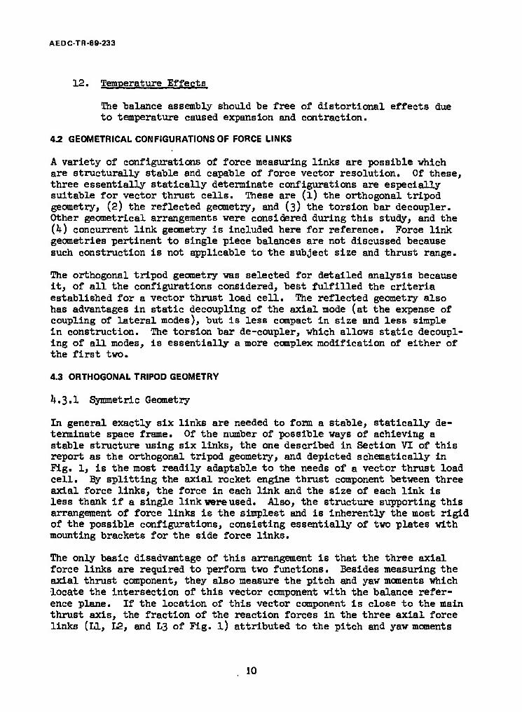
12. Temperature Effects
The "balance assembly should "be free of distortional effects due to temperature caused expansion and contraction.
4.2 GEOMETRICAL CONFIGURATIONS OF FORCE LINKS
A variety of configurations of force measuring links are possible which are structurally stable and capable of force vector resolution. Of these, three essentially statically determinate configurations are especially suitable for vector thrust cells. These are (l) the orthogonal tripod geometry, (2) the reflected geometry, and (3) the torsion bar decoupler. Other geometrical arrangements were considered during this study, and the (4) concurrent link geometry is included here for reference. Force link geometries pertinent to single piece balances are not discussed because such construction is not applicable to the subject size and thrust range.
The orthogonal tripod geometry was selected for detailed analysis because it, of all the configurations considered, best fulfilled the criteria established for a vector thrust load cell. The reflected geometry also has advantages in static decoupling of the axial mode (at the expense of coupling of lateral modes), but is less compact in size and less simple in construction. The torsion bar de-coupler, which allows static decoupl- ing of all modes, is essentially a more complex modification of either of the first two»
4.3 ORTHOGONAL TRIPOD GEOMETRY
4.3.1 Symmetric Geometry
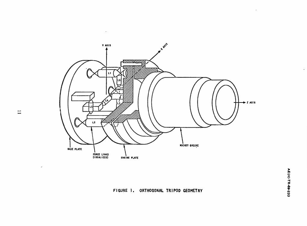
In general exactly six links are needed to form a stable, statically de- terminate space frame. Of the number of possible ways of achieving a stable structure using six links, the one described in Section VI of this report as the orthogonal tripod geometry, and depicted schematically in Fig. 1, is the most readily adaptable to the needs of a vector thrust load cell. By splitting the axial rocket engine thrust component between three axial force links, the force in each link and the size of each link is less thank if a single link were used. Also, the structure supporting this arrangement of force links is the simplest and is inherently the most rigid of the possible configurations, consisting essentially of two plates with mounting brackets for the side force links.
The only basic disadvantage of this arrangement is that the three axial force links are required to perform two functions. Besides measuring the axial thrust component, they also measure the pitch and yaw moments which locate the intersection of this vector component with the balance refer- ence plane. If the location of this vector component is close to the main thrust axis, the fraction of the reaction forces in the three axial force links (LI, L2, and L3 of Fig. l) attributed to the pitch and yaw moments
10
*• I AXIS
ROCKET ENGINE
ENGINE PLATE
FIGURE 1. ORTHOGONAL TRIPOD GEOMETRY
> m o o H 31
& K> U W

AEDC-TR-69-233
will be small relative to the axial force component, and the precision of the location measurements will be more limited than if the moments were measured by force cells which have forces impressed upon them by the moments alone. However, the uncertainty of this location is well within the stated accuracy goals for this study, and would not represent a practical limitation of the application of this configuration.
k.3.2 Asymmetric Geometry
The most straightforward way of reducing the interaction between axial force component and pitch and yaw moments is to locate one of the axial force links (Ll) more closely in line with the main thrust axis (Fig. 2). With this type of asymmetry, reaction forces only appear in the L2 and L3 force links when the axial thrust component deviates from the main thrust axis (z axis). Consequently, the electrical outputs from the strain gage bridges in these two force links would be proportional to the amount of offset, and the superposition of a small force component riding on a large force component within the same force link would not occur. This, however, gives rise to dynamic coupling which would probably be more serious than the small amount of static coupling.
4.4 REFLECTED GEOMETRY
A conceptually simple and direct arrangement of force links is the mirror image of the standard test stand force link geometry, reflected about the forward end of the rocket motor. This arrangement, shown in Fig. 3, uses a single force link to measure the axial thrust, with the five remaining force links at right angles to the thrust axis.
This geometry avoids the problem of static or dynamic coupling of the axial thrust component (Fz) to pitch or yaw moments (Mx end M ); however, coup- ling of these moments with the side force components (F£ and Fy) occurs in this geometry. Since the side thrust components are spatially located beyond the pair (or triad) of side force links forming the resisting couples, one side force link will be loaded in compression and the other in tension. If this distance from the forward side force link to the side thrust component is the same as the distance between links, (say approximately 12 inches) the force in the forward link would be twice that of the aft link and opposite in sign. Since the difference between these two yield the value of the side force component, some loss in pre- cision of the side force component could occur. The loss of precision in this case is about 50^ which is not excessive.
The size of this version for 5000 lbf nominal thrust would be approximately 13 inches in diameter by 18 inches long, and would weigh about 360 lb if fabricated from steel. The supporting structure would be a casting. Com- plexity of machining would prohibit the uae of beryllium. Alluminum would be a possible alternative to reduce the weight, but there is a reluctance to select aluminum because of the difference in coefficient or expansion between aluminum and the steel (n-k PH) force sensors.
12

AEDC-TR -69-233
BASE PLATE
FIXED GROUND
JJMM—ENGINE MTG. PLATE
IDEALIZED FORCE LINKS
FIGURE 2. ASYMMETRIC TRIPOD GEOMETRY, (COUPLED)
13

AEDCTR-69-233
FIGURE 3. REFLECTED GEOMETRY
14

AEDC-TR-69-233
4.5 TORSION BAR DECOUPLER
The torsion bar decoupler is an elastic device which restrains and meas- ures moments in the plane of the decoupler. It provides very little re- sistance to translation caused by force components Fx, Fy, and Fz, and is also relatively flexible for rotations caused by moments in the other two orthogonal planes. As such, two decouplers would be needed for restraint of the pitch and yaw moment components.
The concept of a decoupler was motivated by the need for a device which would allow both static and dynamic decoupling of the large axial thrust component (Fz) from the five other force and moment components (Fy, Fx, My, Mx, and Mz). The axial thrust vector for the symmetric orthogonal configuration is statically coupled to the pitch and yaw moments, and conversely, the asymmetric configuration, which is statically decoupled, has dynamic coupling between the axial thrust vector and all other thrust vector components. Also, the reflected geometry has static coupling be- tween the pitch and yaw moments, and the side forces. Replacement of these configurations with decouplers allows force links to individually restrain and measure single force or moment components.
A geometrical force link configuration using torsion bar decouplers for pitch and yaw moments is shown in Fig. k. This configuration uses a single force link (Ll) to resist the axial force component. The pitch and yaw moments are resisted by pairs of force links (12 and L3, LU and L5) isolated from the axial force component such that each pair essen- tially forms a moment couple. The flexures connecting the torsion bars to the base and to the force links permit each pair of force links to translate relatively freely in the direction of their axes (z direction) when the main axial force link is compressed by the axial force component (Fz). However, a pitch or yaw moment (Mx or My) which would tend to cause the floating plate to pivot out of plane about the x or y axis is resisted by the force link couples. During axial translation of the floating plate (in the z direction) the torsion bars rotate, restrained only by the sup- porting flexures on each end of the bars. This allows axial motion of the pairs of force links. When pitch or yaw moments cause one link of each pair to go into compression and the other into tension, the ends of each torsion bar tend to be twisted in opposite directions.
The pitch or yaw moments appear as compression or tension forces in the four force links and as torques in the torsion bars. These moments may be measured, by a torque cell in each torsion bar or by a force cell in one (or each) of the force link pairs.
This method decouples the axial force measurement from all other force measurements. Pitch and yaw moments and side forces remain dynamically coupled, but are statically decoupled. This torsion bar decoupler does
15

o o H a o> 10 • U U
POSITIONS OF FORCE LINKS
o\
FLEXURES
□n
ENGINE PLATE
ur i i
TORSION BAR LY
|§ I L.
TORSION BAR
BASE PLATE
FORCE LINK, L„
L—.
END VIEW SIDE VIEW
FIGURE k. TORSION BAR DECOUPLER

AEDC-TR-69-233
not dynamically decouple pitch and yaw moments from side forces, because the elastic axes in side translation coincide closely with .the side force links and are, therefore, located some distance from the center of the suspended mass. The remaining dynamic coupling between the side forces and moments is not considered detrimental because these components of the thrust vector are relatively small in magnitude compared to the axial component. It would also be possible to decouple the roll moment M statically and dynamically from pitch and yaw forces and moments using such a device; however, unless precise measurement of small roll torques in the presence of large side forces is needed, this option would not be justified. The symmetric arrangement shown for the two side force cells, L5 and L6, in the basic design, Fig. 1, allows dynamic decoupling, which should be adequate.
One advantage of the torsion bar decoupler is that calibration and data reduction techniques would be similar to existing techniques, because only one axial force link is used.
A further advantage is that the thrust range would be doubled in applica- tions where lateral thrust components would be large enough to cause large pitch and yaw moments. With the basic orthogonal tripod geometry the three axial force links"are required to fulfill a double purpose, and must be sized large enough to handle reaction forces from pitch and yaw moments combined with the axial force component.
An analysis was made of various torsion bar and flexure arrangements. This analysis was carried far enough to validate the feasibility of the torsion bar approach.
The flexibility of the torsion bars and the additional flexures needed would make this method more flexible in response to pitch and yaw moments than the basic design, unless the distance between the force link pairs is increased. By increasing the diameter from lU£ inches to somewhere between 16 and 20 inches (for 5000 lb nominal force) the pitch and yaw moment stiffness parameters and the resulting natural frequencies are equivalent to those calculated for the basic design. Since a single force link is used for axial (Fz) restraint, this link is larger in dia- meter and longer, and the overall length of the assembly will increase from the 8.5 inches of the basic design to approximately 15 inches. The additional size, added components, and added plate and bracket reinforce- ment will increase the weight approximately by a factor of 2.5.
It is expected that interactions resulting from misalignment and deflec- tion will be approximately the same as for the basic design.
The dimensions of a 20,000 lbf unit will increase in the same ratio as the smaller 5000 lbf unit. As an additional note, a 20,000 lbf unit with over- range stops could cover the thrust range from 1000 lbf to 20,000 lbf without
17

AEDC-TR-69-233
change in force sensors. The reason for this is that the axial force sensor can be designed for a higher strain level at maximum load because reaction forces due to pitching moments are not superimposed on the axial (Fz) force reactions.
As mentioned before, the torsion bars need not be aligned parallel to the reference plane; they could be parallel to the main thrust axis. In this case the configuration could be considered a modification of the reflected geometry.
4.6 CONCURRENT LINK GEOMETRY
A possible variation of the basic orthogonal tripod geometry would reduce the reaction forces in the side force links to zero. By aligning the three axial force links, LI, 12, and L3. so that they intersect at a common point, any force component intersecting that point may be entirely resolved by reaction forces in these three concurrent force links. If the focal point were the center of gravity of the rocket engine and mounting hardware, a horizontal installation would produce no tare forces in the side force links, IiU, L5, and L6. Alternatively, if the focus were the gimbal point or point of fluid injection for a thrust vector control system, the three concurrent force links would resolve the side forces.
This method has been used for wind tunnel balances, but for rocket engine testing does not appear to offer any notable advantages. Fabrication, alignment of force links, calibration, and data reduction would be more complex; and this method does not improve either static or dynamic coupling problems. It is discussed here primarily for general information.
18

AEDC-TR-69-233
SECTION V DYNAMIC ANALYSIS
5.1 FREQUENCY RESPONSE AND TRANSIENT RESPONSE
From examination of a chamber pressure versus time record for a rocket engine test firing it is apparent that the nature of the test is dynamic rather than static.^ The chamber pressure builds up to its maximum"value at a rate which is determined by the rate at which the propellant valves are opened, by the dynamic characteristcis of the propellant feed.system, and by the nature of the combustion. After reaching a plateau following a typically rapid initial rise the chamber pressure may oscillate over a small (or a large) range at one or more predominating frequencies until the test is terminated, usually by abrupt closing of the propellant valves.
Since thrust is proportional to chamber pressure one would expect that the recorded thrust history should show a profile of the same shape as the chamber pressure record. However, the thrust data is often degraded by poor response and oscillations caused by low natural frequencies and the inherently low damping common to test stands using precision load cells and flexure pivots as the elastic restraining elements. Generally the problems of measuring all of the six components of thrust are sufficiently difficult that if the plateau phase of the firing can be recorded with good accuracy, one is likely to overlook poor test stand response to start and cut-off transients. This attitude is only justifiable for prolonged operation at a sustained thrust level. If the start transient should be sufficiently steep that the natural frequencies of the test stand are excited, these initial oscillations will decay providing the frequency components in the thrust input to the test stand are not in the vicinity of natural frequencies. Then the oscillations will subside to the point where accurate thrust data can be obtained during the plateau phase of the test.
If it is not possible to avoid an undesirable situation of a rocket engine which excites a test stand to resonance it is still possible to electron- ically condition the test data either before or after acquisition so as to remove objectionable oscillations. The use of low-pass filter is the simplest approach where maximum transient response and frequency response
^Assuming that the chamber pressure transducer and recording system is capable of high enough frequency response to show the dynamic character- istics of the test firing.
19

AEDC-TR-69-233
are not needed.' Other methods which augment the frequency response of the system are acceleration compensation and on-line data reconstruction." Alternatively, the data may be mathematically filtered after acquisition with the aid of digital computers.
The most direct approach for achieving high frequency response is referred to as the "hard" test stand. By using a very rigid structure, high natural frequencies result which greatly enhance the response of the test stand to transient thrust inputs. Ideally, it would also be possible to increase the natural frequencies of the test stand so that they occur above the steady-state components in the thrust frequency spectrum; however, this is usually not possible. Buzz frequencies have been observed to occur as high as l600 Hz, which is well beyond the natural frequencies attainable for the usual range of test stand stiffness parameters and engine mass para- meters applicable to six-component rocket engine testing. Unless buzz or lower chugging frequencies in the rocket engine are known in advance, the best that is hoped for is that the natural frequencies do not closely coin- cide with the driving frequencies. Usually then, the trueamplitudes of these frequencies are attenuated by the absence of response which is char- acteristic of a multiple spring mass system in the region gf the frequency response function well beyond the fundamental natural frequency.
One of the design precepts of the vector thrust load cell concept is low deflection of force cells and flexures under the action of the external forces. (The primary reason for wanting low deflection is that low angular distortions will cause negligible second order interactions.)
The use of the integral balance concept with very rigid elastic flexures and force cells provides low distortion with the additional benefit of natural frequencies which are higher than those usually obtained in six- component test stands. ' Since rigidity is attained by the use of short effective length of elastic elements rather than large cross-sectional
^Loss-pass filters suitable for this type of use usually have four to six complex conjugate poles with equivalent damping ratios of approximately 0.7. This gives a minimal filter overshoot in response to a step-function input and a linear phase, constant time delay characteristic within the pass-band. Consequently the filter attenuates the resonance caused oscillations above the cut-off frequency and leaves oscillations below the cut-off reasonably undiminished in amplitude and undistorted in phase.
°These methods involve an analog solution to the equations of motion for the spring-mass system. In brief, inertial forces computed from the acceler- ations of the mass elements are electronically summed with the elastic restoring forces measured by the load cell to compute dynamic thrust. Acceleration may be measured with an accelerometer or computed by differ- entiating the load cell output (Refs. 2, 3, k, and 5)- A hybrid system uses a combination of the two methods to handle additional degrees of freedom in the spring-mass system (Ref. 5)■
20

AEDC-TR-69-233
areas, it is not necessary to operate at low stress levels which would produce low output voltages from the force cells.
As an estimate of natural frequencies attainable from a vector thrust cell the natural frequencies were computed for the six fundamental modes of oscillation of the basic design analyzed in this study (orthogonal tripod geometry). This was done by solving for the eigenvalues and the eigen- vectors of a dynamic matrix obtained from the stiffness and mass matrix based upon computed parameters. In this computation the total suspended mass of the engine and attaching hardware was lumped at a point on the z axis Ik inches from the balance reference plane. A steel mass of 5OO lb-,, l8 inches long, 12 inches O.D., and 5*1 inches I.D. was selected to repre- sent the engine inertia. (See Fig. 5.)
Table I gives the computed natural frequencies for the six mode shapes associated with the six degrees of freedom. These were computed for three conditions of attachment which need some explanation. The first column of frequencies is for the model in Fig. 5 assuming that the balance is attach- ed to inertial ground. In order to provide a more realistic estimate of natural frequencies it is necessary to account for the flexibility of the engine hardware, and of the structure to which the vector thrust cell would be mounted. An estimate of the contributing stiffness of the test stand and rocket motor interface hardware was provided by assuming that the com- bined effect of both of these will reduce the effective stiffness of the balance by a factor of two. This simply reduces all six natural frequen- cies by i/2} as shown in the second column of frequencies in Table I.
Finally, another column shows natural frequencies for an engine mass of 1000 lbfl and the reduced stiffness parameters. Doubling all inertial parameters again reduces the natural frequencies by S2.
5.2 MODAL COUPLING
For each natural frequency of a vibrating structure there is a correspond- ing natural (or normal) mode of vibration (Ref. 6). Each natural mode is, in general, a combination of translational and rotational harmonic motion at the particular natural frequency. A spring-mass system which has no symmetry in the location and magnitude of the mass and stiffness parameters will have natural modes which exhibit combinations of as many as six possible components of translation and rotation (u, v, w, 0X, 0 , 0Z) measured relative to x, y, and z cartesian coordinates. Such complex mooes of vibration are undesirable in a multi-component force balance because they result in dynamic interaction between the thrust components (Fx, Fy, Fz, Mx, M„, Mz).
Ideally, modes corresponding to the thrust components should be decoupled. (Decoupled modes are also the natural modes*) Then a dynamic force or moment component with the frequency content in the region of the natural frequencies will excite vibratory motion only in the direction of that force component.
21

AEDC-TR-69-233
y AXIS
ROCKET ENGINE MASS, m
z AXIS
FIGURE 5. SPRING-MASS MODEL OF ORTHOGONAL TRIPOD GEOMETRY
22

AEDC-TR-69-233
TABU I
NATURAL FREQUENCIES & MODE SHAPES FOR THE BASIC DESK»
Hode of Vibration
KODE SHAPES (Eigenvectors Normalised to Unity. Dis- placements not shown are sero)
NATURAL FREQUENCIES, Cvcles Per Second
Idealized Rigid Abutment & Engine Hardware
Combined Stiffness of Abutment & Engine Hardware Equal to Load Call
Stiffness
Axial Translation w - 1.000 in.
H - 500 lb D K = 500 lb ■ M - 1000 lb, ■
225 159 112
Taw Translation and Rotation
u - 1.000 in. «L- 0.056 rad.
a.6.8 33.1 23.4
Pitch Translation and Rotation
T - 1.000 in. dy-0.057 rad.
47.5 33.5 23.7
Roll Rotation * = 1.000 rad. 94.2 66.7 47.1
Taw Rotation and Translation
<b=-0.476 rad. u7- 1.000 in.
278 196 139
Pitch Rotation and Translation
e> « 0.461 rad. v*- 1.000 in.
296 201 148
Inertia Parameters
Kass, lb m 500 1,000
Moment of I Inertia, I**
m zx
Stiffness Parameters
18,800 18,800 10,600
37,600 37,600 21,200
Transla- k tion kx
lb/in k*
0.511 x lo£ 0.598 x 10* 2.590 x 10°
0.255 x 10? 0.299 x 10? 1.290 x 10°
Rotation k in-lb kjx
kjj 39.1 x 10J? 36.2 x 10?
9.75 xlO6
19.55 x 10J? 18.10 x 10? 4.87 xl0°
23

AEDC-TR-69-233
For example a pure axial force Pz would only excite vibratory translation if the mode corresponding to translation in the z direction were decoupled. Also a pitching moment My would excite only pitch rotation if the 0X mode were decoupled.
The important point here is that it is desirable that the dynamic response to the particular force component should not cause oscillation in one of the other cartesian directions. Such oscillation would erroneously indi- cate dynamic excitation corresponding to force components in that direction.
The decoupled condition may be visualized more clearly in terms of static deflection. If a thrust component, say Fz, is dynamically decoupled, then application of that component alone will only cause translations deflection (or rotation for a moment) in that direction. Also, there exists a line-of-action for the application of each force component which will cause translation only. If this line, called the elastic axis (Ref. 7), coincides exactly with the mass center-of-gravity of the suspended portion of the balance, that mode is a natural mode and is decoupled.
It is neither practical nor necessary to decouple all cartesian modes of a six-component rocket engine balance. However, it \B important that the axial mode be decoupled from the others because of the relatively large magnitude of the axial force component Fz. This is especially true for symmetric motors without thrust vector control where accurate definition of very small side forces and moments is desired. If the axial mode were coupled to the other cartesian modes, oscillations in the side direction would be excited when the forces corresponding to those cartesian modes were zero. Consequently, very small side force moment components would be obscured by large oscillations excited by the axial force component Fz. These oscillations could be filtered from the thrust record, but if the oscillations were much larger than the magnitude of the thrust component, a low cut-off frequency would be needed to sufficiently attenuate the oscillations. Extreme linearity in the test stand, filter, and amplifiers, would be needed to avoid a bias in the filtered residual.
The existence of coupling between the axial mode and the others was the primary reason for rejection of the asymmetric orthogonal geometry from further consideration. For this geometry, the location of the z axis close to or directly on one of the axial force links L^ would cause the most severe type of modal coupling. An F2 force component existing alone would cause static pitch and yaw rotation of the balance, which under the action of dynamic loads would result in rocking motions including both rotation and translation in the pitch and yaw directions.
It is possible that the majority of rocket engines tested would not possess frequency content in the thrust spectrum capable of exciting the natural frequencies of the asymmetric design to resonance. However, since it is
24

AEDC-TR-69-233
possible to avoid this possibility by taking advantage of symmetry, the symmetric orthogonal geometry was chosen to represent a basic design. Other geometrical configurations which have uncoupled axial modes are the reflected geometry and the torsion bar decoupler.
The mode shapes (eigenvectors)for each natural mode of vibration are given in Table I. Roll rotation is decoupled as well as axial trans- lation (a factor which is not particularly important in the performance of the balance). Modes two and three have the lowest frequencies because the rotation and translation are in the same direction. Modes five and six are primarily rotational pitch and yaw with translation occurring in the opposite direction from rotation.
25
AEDC-TR-69-233
SECTION VI DESIGN ANALYSIS
6.1 ORTHOGONAL TRIPOD GEOMETRY
Of the various force link configurations which are applicable to the concept of the vector thrust load cell, the orthogonal tripod configur- ation was selected for detailed analysis. This configuration is the most compact in size and lightest in weight; thus it conforms best to the precepts of an integral, semi-portable rocket engine balance. It is the simplest configuration to design, fabricate, assemble, and align; therefore it is the most economical.
6.1.1 Description
Six force measuring links are arranged in a stable, essentially static- ally determinate array as shown in Figs. 1, 7, and 8. Three axial force links (LI, L2, and L3) aligned parallel to the thrust axis and located at the corners of an equilateral triangle restrain and measure the axial force component (Fz) and the pitch and yaw moments (Mx and My). The three side force links (LU, L5> and L6) located in the xy plane re- strain and measure the pitch and yaw force components (Fx and Fy) and the roll torque (Mz). The plane locating these side force links is re- ferred to as the balance reference plane, because the intersection of this plane and the thrust axis (z axis) is the most logical origin for the cartesian coordinate system.
The following equations express the external force link reactions. (These equations are covered in more detail in Section VIII. See Fig. 6 for the sign convention.)
(Axial Force) F„ — RT + Ro "*■ Ro
(Yaw Force) FX = RU
(Pitch Force) Fy =-(R5+R6>
(Roll Moment) Mz = R5x5 + RgXfc-
(Pitching Moment) Mx = Riyi+ ^2 + B
(Yaw Moment) My = -(RgXa + R3X3)
(Resultant Force) F =3/Fz2 + Fx2 + Py2
(1)
26

AEDC-TR-69-233
Y AXIS
FORCES ARE POSITIVE IN THE DIRECTIONS OF THE ARROWS. MOMENTS ARE POSITIVE ACCORDING TO THE RIGHT HAND RULE. ALL FORCES ARE CONSIDERED TO BE APPLIED TO THE ENGINE SIDE OF THE BALANCE. FORCE LINK REACTION FORCES ARE CONSIDERED POSITIVE IN COMPRESSION.
BALANCE REFERENCE PLANE (ENGINE SIDE)
FIGURE 6, EXTERNAL FORCE AND MOMENT COMPONENTS AND FORCE LINK REACTION FORCES, ORTHOGONAL TRIPOD GEOMETRY
27

oo
X AXIS I AXIS -
> m O O H 3) I
CO
K> U U
FIGURE 7. VECTOR THRUST CELL - SECTION THROUGH REFERENCE PLANE
FIGURE 8. VECTOR THRUST CELL SIDE.VIEW (SECTION AA)

AEDC-TR-69-233
The axial force is measured as the sum of the three axial force link reactions, the yaw force is equal to a single side force link reaction, and the pitch force is equal to the sum of the other two side force link reactions. Pitch, yaw and roll moments are computed from the sums of products of reaction forces and distances. The xy plane through the side force links is defined as the balance reference plane. The location of the resultant thrust vector in this plane is given by the following two equations:
M — x
(2) %
These equations are derived on the assumption that the force link pivots are perfect pin .joints. This is essentially true, and the actual magni- tude of flexural restoring forces is covered in Section 7-^.
The location of the three axial force links gives what might be described as a milk stool arrangement (Fig. l). These links act as spacers for two metal plates which are attached respectively to the test stand (base plate) and to the rocket motor (floating plate). The three side force links are located half-way between the base plate and floating plate in the balance reference plane (xy plane). These side force links are attached to the plates by means of stand-off brackets. The plates are attached to the test stand and to the rocket motor mounting hardware by three attachment points per plate. This three point'mounting-is intended to minimize warping of the plates in,the process of fastening them to the interface hardware.
6.1.2 Basic Design Parameters
The nominal measurement range of the basic design analyzed under this heading is 1000 lbf to 5000 lbf. A similar unit of larger capacity would cover the same ratio but at the higher nominal level of 1*000 lbf to 20,000 lbf. It is expected that the actual thrust range of the balance will exceed this 5:1 ratio as explained in Section 6.3. The input thrust vector parameters and internal reaction forces are summarized in Table II for the 5000 lbf nominal range. Computed deflection and stiffness para- meters are given in Table III.
29

AEDC-TR-69-233
TABLE II
THRUST VECTOR PARAMETERS
1000 LBF TO 5000 LBF NOMINAL RANGE
Fz, Axial Thrust Component
Nominal Thrust° Range
Maximum Thrust with Mx and My = 0
Thrust-Vector''' Components
("5000 lbf \1000 lbf
10,000 lhf
Fx, Yaw Force Component (max.) ±1000 lhf
Fy, Pitching Force Component (max.)
3My, Yawing Moment (max.)
Mx, Pitching Moment (max.)
9, Girnbal Angle (max.)?
z, Girnbal Location (max.)?
Mz, Roll Torque (max.)
+1000 lhf
12,500 in.lh
12,500 in.lb
11.5^°
12.5 in.
2000 in.lb
Force Link? Reaction Forces
R1,R2,R3 = 1666 lbf
R!,R2,R3 = 333 lbf
RX,R2,R3 = 3333 lhf
R2^ = +1000 lbf
R5,Rg = ±500 lbf
R2 = -R3 = -12A2 lbf
Rx = -1666 lbf, R2 - R3 = 833 lbf
\5 —ng = -250 lbf
fThese force values may be multiplied hy a factor of k and the moment values hy a factor of 8 for the k,000 lbf to 20,000 lbf nominal range.
"This value could be exceeded if the pitching moments were less than 12,500 in. lb.
^These values could be exceeded if the axial thrust were less than 5,000 lbf.
30

AEDC-TR-69-233
TABLE III
CALCULATED DEFLECTIONS AND STIFFNESS PARAMETERS
ORTHOGONAL TRIPOD GEOMETRY
LOAD DEFLECTIONS STIFFNESS
Fx = 1000 lbf Plates & Brackets 0.456 x 10 i. in. Force Links 1.502 x 10"J
Total u = 1.958 x 10~3 in.
kx = 511,000 lb/in.
F = 1000 lb. y *
Plates & Brackets 0.236 x 10~3 in. Force Links 1.432 x 10--5
k - 598,000 lb/in.
Total v = 1.668 x 10~3 in.
F = 5000 lb, Z i
Plates 0-432 x 10~3 in. Force Links 1-503 x 10"°
k = 2.58 x 10~6 lb/in z
Total w = 1.935 x 10"3 in.
Mx = 12,500 in-lb Plates (0.117 + 0.054) x 10'3 in. Force Links (1.490 + 0.745) x 10"J in.
k_ = 39.1 x 10"6 in-lb ^ rad.
Total (1.607 + 0.799) x 10~3 in.
*x = 0.320 x 10"3 rad.
M = X2.500 in-lb y Plates 0.194 x 10~3 in. Force Links 1.304 x 10"^
K_ = 36.2 x 10~6 in-lb * rad.
Total 1.498 x 10"3 in.
*v = 0.346 x 10"3 rad.
M = 2000 in-lb z
Plates & Brackets 0.122 x 10 ~ in. Force Links 0.700 x lO"-'
k~ - 9.75 x 10"6' in-lb ~ rad.
Total 0.822 x 10"3 in.
* = 0.205 x 10"3 rad. z
31

AEDC-TR-69-233
Referring to Figs. 7 and 8 the cartesian coordinate locations of the force links are given in Table IV, where the subscripts refer to force link numbers, and the letters "A" and "BM designate connection to test stand mounting plate and engine mounting plate respectively. Balance dimensions and estimated weights are given in Table V.
TABLE IV
FORCE LINK LOCATIONS
Force Links
Xl = o yi = +5.0"
x2 = -U.33" y2 - -2.5"
*3 * +U.33" y3 = 2.5"
- - yit - 0
x5 = -k.00"
x6 = +1+.00"
k = z5 ■ z6 " ° ZIL =
Flexures
Z1A = Z2A = Z3A = -2.25"
Z1B = Z2B = Z3B " +2.25"
x^B = -I.T5"
y-5A - y6A ■ ^«50"
y5B - y6B = -0.375"
Reference Radius
r = yi = 5.0"
Outside Diameter
Plate Material
Balance Depth
Plate Thickness
Balance Weight
Mounting Bolts
TABLE V
BALANCE DIMENSIONS
lit.25"
17-kPH Aluminum Beryllium
8.5 in. 9.5 in. 8.5 in.
2 in. 3 in. 2 in.
225 lb. 125 lb. 72 lb.
Three 3A" diameter bolts on a 13" diameter bolt circle.
32

AEDC TR-69-233
6.2 FORCE LINK DESIGN
Two approaches to the design of force cell and flexure assemblies were studied. A search was made to see if commercially available load cells and flexures would be suitable, and an analysis was made of force cells and flexures which would be specially designed and fabricated.
It was found that commercially available flexures of the circular arc type would readily meet requirements. Catalog flexure dimensional para- meters would be modified somewhat to optimize stiffness parameters, and special fittings would be designed to allow greater convenience in assem- bly, alignment, and replacement of force links (see Fig. 9, also Ref. 8, 9, and 10). In general, the manufacturer's catalog specifications were capable of providing the combination of axial rigidity and bending flexibility needed. However, torsion flexures would best be designed as an integral part of the force cells to maximize axial rigidity and minimize force link length, consistent with compact design.
The circular arc flexure is well suited to applications which require low deflection along the main load carrying axis. This type consists essen- tially of a short, wide strap with cylindrical sides which allows a fixed center of pivot and has very small change of restoring moment as a function of axial load. No lateral restraining straps are needed, which makes for simple, rugged and precise construction. The pivot center is very accur- ately located relative to the pilot diameter of the flexure which aids precision force link alignment. Either the compound or the universal type can be used. The compound type has two straps in tandem which are orientated at right angles so as to allow bending in two orthogonal planes. The universal type also has two degrees of freedom in bending ex- cept that the straps are folded so that the pivot centers are coincident. Although this type of flexure is relatively stiff in bending compared to flexures with longer straps, the small angular deflections of the balance will result in low restoring moments. -
The most efficient design procedure for obtaining minimum axial deflection from a flexure is (l) reduce the cross-sectional area consistent with the stress rating of the material, (2) increase the width-to-thickness ratio to a maximum depending on the allowable flexure diameter, and (3) set the flexure length at a value which gives sufficient bending flexibility. This method minimizes the strap thickness, which is the most sensitive bending stiffness parameter. ^-O It should be noted that the alternate practice of obtaining axial stiffness by using a flexure with a large length-to-thickness ratio and selecting a size with a load capacity in excess of the capacity actually needed will produce a less than optimum ratio of axial stiffness to bending flexibility.
10For a flat strap the axial stiffness is k = AE/| 3 and the bending stiffness is k* = IE/]? = y* E
* 12JL
33

AEDC-TR-69-233
#10-32 SCREWS "V
WELDED CAP
TORSION REXURE
STRAIN GAGE AREA (INSIDE)
CIRCULAR ARC FLEXURE
SECTION B-B TORSION FLEXURE
SECTION A-A FORCE SENSOR
END VIEW
FIGURE 9. SIDE FORCE LINK L4 - 1000 LBp
34

AEDC-TR-69-233
Torsion flexures were found to be needed for the axial force links because circular arc flexures are relatively rigid in torsion. Again, to minimize axial deflection, a short flexure is selected. A cruciform cross section gives a satisfactory axial-to-torsion stiffness ratio.
Commercial load cells which use semiconductor or foil strain gages will satisfy requirements for low deflection and high precision. Some of these have been used for rocket engine thrust measurement, and tests have been made on them to evaluate their sensitivity to side loads, bending moments, and torsional loading. These tests indicate that such load cells would be adequate for rocket engine force balances; however, the end fittings and size are not the most conducive to convenient assembly and alignment or to compact design. For these reasons, the basic design analyzed in this study uses specially designed force cells which are more readily suited to the special requirements for a rocket engine force balance.
The three basic categories of strain, namely compression, bending, and shear, were compared for applicability. The compression mode was selected because it provides minimum axial deflection and is the most compact. Using a four-element strain gage bridge, two strain gages which are axially aligned sense the full value of axial strain, and the two strain gages aligned at right angles to the force cell axis sense the strain due to the Poisson ratio effect. This arrangement gives 65$ of the output of a bending element sensor since the Poisson ratio strain is only 30$ of the axial strain. For this same reason, strain gage non-linearity is not cancelled entirely and highly linear semiconductor strain gages are needed. Successful compression force sensors using such gages have been designed, built, and tested.
Each of the six force links is a subassembly of three elements. The center element has the force sensor in line with a cruciform torsion flexure. Attached to each end is a compound flexure pivot of the circular arc type which gives two degrees of freedom in bending. The force cell is attached to the flexures by four cap screws in such a way that the force cell may be removed and replaced without removing the flexures from the plates or the mounting brackets. These flexures are also attached to the plates and mounting brackets with four cap screws and are dowel pinned or piloted in place to insure that force link alignment cannot be disturbed. By this arrangement the force cells may be removed and replaced after the balance assembly has been calibrated without disrupting alignment of the force links.
Analysis of.the sensitivity of such elements to lateral forces and torsional moments is straightforward, and the results of this analysis are that the force sensor design presented here is essentially insensitive to the small redundant forces and momentstransmitted by bending and torsion of the flexures.
35

AEDC-TR-69-233
Each of the center force cell elements is a strain gaged compression column with a torsion flexure on one end. The cross section of the compression column is either a hollow square or a solid square with the strain gages bonded either to the inside or to the outside. Adequate space has been provided for dual strain gage bridges.
Semiconductor strain gages are recommended to provide high signal levels at low force inputB. A low resistivity gage would be selected with a gage factor of approximately 55. Such gages are capable of excellent linearity and are excited by the usual constant voltage power supplies. Experience with this type of strain gage has shown that the non-linearity is less than 0.05$. These gages are compensated for temperature effects on zero and span. Provision for shunt resistance calibration would be included.
The severe environment of a rocket engine test cell requires that the force sensors be individually protected by hermetic seals. By placing the strain gages within the hollow square compression column, the entrance to the gages can be sealed with a welded cap. Hence it is not necessary to use diaphragms or other flexible sealing elements which could be potential sources of hysteresis, temperature drift, arid environmental pressure sensitivity. (The force resulting from ambient pressure changes is equal to the value of the pressure times the cross-sectional area of the strain element). This same type of protection is easily adap- table to shear elements, but for bending elements,diaphragms would be needed. The straightforwardness of this design concept plus actual ex- perience with similar designs gives confidence that such force elements can be provided with minimal development effort.
Tentative specifications for the force cells are established in Table VI for the 5000 lbf nominal thrust range. The parameters listed are the same for the 20,000 lbf vector load cell except the force values would be multiplied by four.
36

AEDC-TR-69-233
TABLE VI
TENTATIVE FORCE CELL SPECIFICATIONS
Axial Force Cells LI. L2, L^
Side Force Cells Lk. L5. L6
Nominal Thrust Vector Components
F2 = 5000 lhf Fx = 1000 lbf, Fy = 1000 lbf
Nominal Reaction Force Per Link
RX = R2 = R3 = -1666 lbf R^ = 1000 lbf, R5 = Rg = 500 lbf
Over-range Ratio11 6x 3X
Nominal Strain Level -250 X 10 "6 in. ,/in. +500 x 10~6 in./in
Linearity12 ±0.05# +0.10#
Hysteresis 8s Non-Return-to-Zero
0.02# 0.02#
Zero Shift with Temperaturel3
0.005VF 0.005^/F
Span Variation with Temperature1^
0.005#/F 0.005#/F
Nominal Output i+5 mv 90 mv
Input Voltage 5 volts 5 volts
^Without excessive non-return-to-zero.
■^Maximum deviation from a straight line intersecting the zero and nominal load points. For semiconductor strain gages the calibration curve can be represented by a second degree equation (no inflection) over this range. Consequently, the linearity improves as the nominal strain level is decreased. At the low strain levels encountered at small side forces the non-linearity in the LU, L5, and I»6 force cells would be immeasurable.
^These are typical values which can be improved with additional effort spent in temperature compensation.
37

AEDC-TR-69-233
6.3 MEASUREMENT RANGE
The range of thrust considered in this study is 1000 lbf to 20,000 lbf. For the basic design the nominal resultant thrust chosen was 5000 lbf at an angle of 12° and at a location of 12.5 inches from the balance reference plane. If the gimbal angle were zero, 10,000 lbf axial force would be allowed, and this could be increased to 20,000 lbf if over-range stops were provided.. So, essentially we are referring to a 5000 lb balance which is useable to as low as 200 lb force (given certain conditions as later described). A 20,000 lbf (nominal level) balance would be essen- tially the same design except it would be somewhat larger in order to accommodate the larger force cells, flexures, brackets, and plates.
6.3.1 Resolution of Forces and Lower Balance Limit
When only one external force component is reacted by one or more force links the measurement precision of that force component is a function of the re- peatibility of the force cell and flexured structure and the resolution of the data acquisition system. Strain gage load cells may be operated at very low strain levels with excellent precision, given a quiescent tempera- ture environment and a signal-to-noise level adequate for the data acquisition system.
High precision foil gage load cells have shown repeatabilities of better than .001$ when loaded to full scale (approximately 1000 x 10"6 in/in) under a laboratory-controlled temperature environment (Ref. 111-). Also, thrust data repeatable to 0.5$ of full scale have been taken during rocket firings using semiconductor strain gages at the 2 x 10"° in/in strain level. From these examples and from general experience it would seem that 10"° in/in represents a reasonable lower limit on strain resolution. This implies that a semiconductor force cell with a nominal strain level of 500 x 10"° in/in could be loaded to 1/50 of the full scale level and still produce 0.1$ resolution or better. Although this is highly dependent on the data acquisition system and the electrical noise level, use of semiconductor strain gages which will give an output voltage of 90 mv at full load and 1.8 mv at l/50 of the nominal level should allow operation over the 50:1 range. • Foil gages utilized at comparable strain levels produce 1 mv/volt output which would give a comparison range of 0.3 to 15 my output. Since the nominal strain level of the basic design is 500 x 10"° in/in at 10,000 lb of axial thrust, this analysis shows that the lower limit of measure- ment would be approximately 200 lb axial thrust (plus any conceivable combination of side loads and moments).
If there were no limitations in the data acquisition equipment, the lower measurement limit of the balance would be largely determined by balance zero temperature stability. In adverse thermal environments, the stability could be augmented by a cooling jacket such as is sometimes used with in- ternal wind tunnel balances. The inherent compactness makes the vector thrust cell basic design well adapted to such water cooling.
38

AEDC-TR-69-233
6.3.2 Upper Balance Thrust Limit
A wide usable thrust range is a desirable quality for any force balance. For typical rocket engine testing the usual design limit for force sensor strain at the nominal thrust load of the rocket engine is 1000 micro-inches per inch. At this strain level the load cells produce the maximum signal level without encountering excessive non-linearity or non-repeatability. In order to operate at this strain level some advance knowledge of the
' combustion characteristics for the rocket is necessary to assure that the frequency content in the thrust vector will not produce large overshoot or oscillations in the thrust stand which will cause overload strains. Normally, for semiconductor gages, this upper limit is set at 1500 to 2000 micro-inches per inch. Consequently, when the specific thrust char- acteristics of an application are not known a lower nominal strain level is used as a safety factor..
6.3.3 Overload Stops
To protect a load cell against overloads some type of mechanic al stop is often incorporated. In the vector thrust cell such protection is achieved by installing spacers between the mounting plates and brackets with a small clearance (0.00l+ in. approximately) which closes when the maximum allowable stress is reached. It is necessary to provide additional brackets for the basic design to accommodate lateral overloads in tension. Accordingly, the size of the basic design would increase slightly from that given in Table VI.
An alternative method of providing protection against overloads is a mechan- ical release. The base of the balance is forced against a set of attachment points by preload springs set to release at the overload thrust level. When release occurs the entire balance moves in the direction of the force and the floating plate bottoms out against the overload stop. The springs have low stiffness so the force does not change appreciably during the small amount of travel. Such devices have to provide for tension and compression in the side force units.
If some type of over-range force protection is provided for the basic design, the maximum range of this balance could safely be doubled. Hence either a pure axial load of 20,000 lbf or a resultant force of 10,000 lbf at 9 = 12° located at 12.5 inches from the balance reference plane would produce 1000 microinches per inch in the axial and side force cells. This would allow a leeway of 500 to 1000 microinches per inch for closure of the over-range stops and further deflection of the arresting structure.
39

AEDCTR-69-233
SECTION VII INTERACTION ANALYSIS
The accuracy of a multi-component force balance is largely dependent on the effect of interactions between force measuring links. If it were possible to construct a perfect balance without interactions, the accuracy attainable would only depend on the precision of the force cells and the accuracy of the calibrator. The objective of having zero interactions between force links cannot be entirely realized in a practical balance, because of the following effects:
1. Superposition of forces within individual force links
2. Lack of perfect angular alignment of installed force links
3. Angular distortion due to deflection under load
k. Restoring forces and moments resulting from stiffness of flexures.
This section will discuss interactions in general, and will explain how they relate in particular to the basic design. The analysis will estimate the magnitude of these interactions for various representative loading conditions.
7.1 SUPERPOSITION OF FORCES WITHIN INDIVIDUAL FORCE LINKS
Optimum resolution of force vectors in a multi-component balance is achieved when force links individually restrain and measure only single force and moment components. The ability of a force link to resolve re- action forces is decreased when reaction forces from two or more external force and moment components are superimposed within the same force link. This effect may be classified as a superposition interaction, and as such is the only type of interaction which is not repeatable and cannot be ex- tracted from test data by the use of calibration data.
Superposition of two force components within the same force link would have the most limiting effect on resolution when one component is much larger than the other. This occurs in the orthogonal tripod geometry when the thrust vector is comprised essentially of the axial component and all other components are relatively small, a situation which would be typical of symmetric rocket motors with no thrust vector control system. In this case the relatively small reaction forces from pitch and yaw moment compon- ents Mx and My are riding on top of the full value of the reaction forces due to the axial force Fz. Since these moments establish the location in the reference plane, the uncertainty of this location is
40

AEDC-TR-69-233
a function of the precision of the axial force links as well as the degree of superposition. The following analysis will explain the use of the terms uncertainty and precision and will estimate the uncertainty of the thrust vector location due to this superposition effect.
The Fz, Mx»and My components are expressed by the following force and moment equilibrium equations (see Fig. 6).
Fz = Rx + R2 + R3
My = -(RgXg + R3X3) (l repeated)
Mx = Riyi+ ^2 + ^3
These three equations when solved for the axial force link reactions give:
R2 = i Fz- U^-^My) (3)
The location of the line-of-action is given by the ratio of the pitch and yaw moments to the axial component:
- Mj. - (Rg xg + R^)
(M
As background to the statistical nature of measurement accuracy consider the example of a balance which has been calibrated and is now being repeatedly loaded by an axial force Fz = 5000 lbf. The force link reaction forces Rp Rg* and Rg are determined from recorded strain gage bridge voltages Et multiplied by proportionality constants C^ (see Section 8.l). The set of repeated values of x and y calculated from equations (l) and (2) can be statistically reduced to obtain estimates of the population mean values //^ andyU—, and standard deviations (Tjr and <T—, These are computed as follows:
/7— xi + X2 + + 3Tn /*x = x = individual sample 11 i of 5?
Tx « /(*L)C
+ (x2r + — + (^P i - 1,2,3— n . l5J . /(5j)2 * (xg)2 * — I (x^) J n-1. n = number of measurements
41

AEDC-TR-69-233
If a large number of sample determinations of x and y are obtained, the values of JUx,My, (Tx, and (Ty1 calculated from equation (5) will be good estimates of the population means and standard deviations. Also, if the balance has been accurately calibrated such that the proportionality con- stants Cj_ are exactly known, the mean values obtained will be good estimates of the thrust vector locations x and y. In this case the true values of x and y are zero because the 5000 lb force is assumed to coincide with the z axis.
We expect from experience (and from the Central Limit Theorum, see Ref. 12)^ that these sample measurements will be normally distributed. In other words the probability distribution of the population from which these samples were taken can be described by the normal (or Gaussian) probability density function which plots as a symmetric, bell-shaped curve. The precision of a measurement is commonly stated as limits of deviation from the mean within which the confidence level is 95$. If the variability of the measurement is normally distributed the precision is defined by the ±2T limits of the normal curve. The area enclosed by +2T represents a probability of O.95 that the measured value will fall between these limits.
At this point we are involved in an analysis of an instrument which has not been built and tested. Although data is not available which would allow us to directly calculate the standard deviations and determine whether the probability density function is normally or otherwise distri- buted, we can apply the history of experience on similar force measuring transducers as a basis for estimating the precision of location of the thrust vector. To distinguish between standard deviations established from statistical analysis of test data and the precision we are estimating, we refer to estimated precision as the uncertainty of the measurment. The uncertainty is defined as twice the standard deviation, and the dis- tributions of the location variables x and y and the force link reactions, Rp R2 and Rg are assumed to be normal. The uncertainties are then:
A x = 27"x
Ay = 2(Ty- (6)
AR = 20" R
It is seen from equations (l) that the pitch and yaw moments which deter- mine the locations x and y depend upon the magnitudes of reaction forces R\> ^2» an(* R3 (as measured by strain gage bridge voltages Ej_, Eg, and Eg times sensitivity constants Cp Cg and Co and the force link locations X-, x_, x_, y-, y2, and y ). The thrust vector locations are also a function or interaction terms (see^Sections 8.3, Q.k, and 8.5) which are relatively insignificant in this analysis. The parameters which are most likely to exhibit deviations from the values obtained during calibration are the
42

AEDC-TR-69-233
sensitivity constants C1? C2 and Co of the axial force links. The force link locations are fixed, and the values of these force link locations in terms of the electrical centers of the force links obtained "by appli- cation of calibration loads differ from the physical locations by only 0.1$ (because of -flexural redundancy, see Sections f.k and 8.2). It is ex- pected that the locations of these electrical centers would shov very little variability during testing because any such variability would have to be caused by change of flexural stiffness, and such changes would only affect the 0.1$ part rather than the physical part of the force link locations. It is also expected that no excessive temperature gradients will be present in the balance which would distort the structural geometry and thereby introduce spurious flexural moments which would not be repeatable or predictable. For this same reason the force link alignment will not change during testing, and therefore any misalignment interactions ob- tained during calibration will be constant.
Having established that the precision Ax and Ay of the thrust vector location is a function of the precision of the force cells which mea- sure the random variables Rj_, R2, and R3 we can determine the location precision from knowledge of the precision of typical force cells (including the precision of data acquisition channels). In this discussion of pre- cision we are concerned with the ability of the force cells to produce the same electrical output voltages each time the input forces are exactly repeated. The precision of a force cell is expressed as a percentage of the force to which it is loaded (provided that the force cell is loaded within its usable range as discused in Section 6.3.1). A strain gage force cell of the type we are considering is capable of short term precision in the range of 2 0" = 0.1$. For the period of time between pre and post-run calibrations during which the hot-fire testing is performed an estimated precision or uncertainty of reaction forces AR = .001 R is considered reasonable for estimating the uncertainty Ax" and AY of the thrust vector location.
We are mainly•concerned with the ability of force cells to precisely dis- tinguish between small reaction forces caused by the moment components tthe terms in parentheses in equations (l)] and the much larger reaction forces due to the axial Fz component [given as the i- Fz terms in equations (l)] . As an example of how a large force will limit the precision of a small force take the case of a 10 lb force and a 5000 lb force applied simultaneously to a load cell which has a known precision of 0.1$. The uncertainty of any individual measurement of total force is equal to + .00}. (5010 lbf) = + 5 lbf (with a 95$ confidence level, assuming normal distribution). Consequently if the larger force were exactly known and it were desired to determine the value of the smaller force, the uncertainty of this determination would be + 50$ of 10 lbf. It is seen in this case that the ability to accurately measure the small force component has been greatly reduced by the simultaneously applied large force. If the large force had not been present the force cell would have been calibrated over a 10 lbf range. The precision associated with that range would have been + 0.3& of 10 lbf instead of ± 50$.
43

AEDC-TR-69-233
Referring back to equations (2) we see that the locations 5T and JT are the sums of the reaction forces times the force link lengths divided by the axial force component. Although the values of the reaction forces Rj, R/>* and R3 are not independent (since they are proportioned by the moment arms of the balance) the randomness or uncertainty in the measurement of these reaction forces are properties of the individual force cells and individual channels of the data acquisition system. Consequently the reaction forces are statistically independent, and the standard deviations of the computed values of x and y are equal to the root-sum-squares of the standard devia- tions of the individual terms on the right hand sides of equations (2) (see Ref. 12, p^_ 118). Using this to express the 20" uncertainty of the measurement of x and y in terms of the force cell 2(T precisions AR gives:
- 1 / 2 2 x = fz J {A RgXg) + (AR3x3r
Y = F2 y CAR1y1)2 + (&fy2f * (M3y3f (7)
Substituting AR* = .001 (- F ) and also substituting the nominal values for the force link locations ^ and y± gives the estimated uncertainties of the thrust vector location:
x = FZV/(-°°D2 (3 Fz)2 [(^-33)2 + (U.33)2] - .002 in.
7 - ^ yt.OOl)2 jl T»f \ (5)2 * (2.5)2 + (2.5)2]= .002 in.
The uncertainty would be proportionally larger for balances with greater spacing between the force links. This is one reason why the natural fre- quencies of the lateral modes were not increased by increasing the force link spacing (the other reasons being that these frequencies already seemed adequately high, and compact design was one of the criteria).
The conclusion of this analysis is that the resolution of the location of the line-of-action of the thrust resultant should not present a serious limitation in the majority of applications for which this force balance is intended.
7.2 INTERACTIONS DUE TO MISALIGNMENT
One of the greatest sources of repeatable interactions in a balance of this type is misalignment of force measuring links. A small amount of force link misalignment will be present after the balance has been assembled and aligned, and further misalignment will occur when the balance deflects under load. Initial misalignments cause linear, first order interactions which are readily extracted from test data after these interactions have
44

AEDC-TR-69-233
been determined by calibration. Additional misalignments which result from angular distortion of force links under load give rise to nonlinear, higher order interactions, which are objectionable because of the addition- al number of calibration loadings needed to evaluate them.
The basic mechanism of misalignment interaction will be illustrated by the simplified arrangement of force links as shown in Fig. 10. The two- dimensional balance shown has two axial force links and one side force link, and the thrust vector is in the plane of the force links. Each force measuring link is considered to have a perfect pivot on opposite ends so that restoring forces are zero. The three reaction forces which are co-linear with the force links restrain and measure the external thrust vector. This vector may be conveniently defined by its three orthogonal components Fz, Fy, and M, or by its magnitude, angle, and location, F, 9, and y. The two sets of components are related by:
F = JFZ2 + Fy
2
e = SL (9) Fz
7 Fz
The reaction forces in the force links are given by the following equations, assuming that the lines-of-action through the force link pivots are exactly orthogonal to the coordinate axes.
Fz = RL + Rg
Fy = R3 (10)
M = R^ + \v2
If y2 ■ -y-j.' solving for Rl> ^2* anä *H gives:
(11)
R3 = Fy
45

AEDC-TR-69-233
a. BALANCE AND LOCATION PARAMETERS
R,
^C b. CARTESIAN INPUT FORCE COMPONENTS AND REACTIONS
T FIGURE 10. SIMPLIFIED TWO DIMENSIONAL BALANCE
46

AEDC-TR -68-233
7*2.1 Misalignment of Axial Force Links
For the first example of a misalignment interaction we shall examine the effect of equal misalignment of both of the axial force measuring links as shown In Fig. 11. We are assuming that for this case the external force vector coincides exactly with the z axis so that each reaction force is approximately equal to F/2. Since only initial misalignments are being considered here, the deflections are assumed equal to zero. As the dia- gram shows, both force links are misaligned in the same direction by an angle I. Because the idealized pivots allow no restoring moments, the line-of-action of the reaction forces R^ and R2 must coincide with the center lines of L^ and L2 and must therefore be misaligned by the same angle, g . For equilibrium in the y direction the side force measur- ing link has a reaction force of R3 = (R^ + BQ) sin I . Because of the small value of the angle I this is approximately equal to Ro = (R]_ + fyW
. Also, since the cosine of % is nearly unity there is essentially no error in the determination of the magnitude of the input force vector.
F = F2 = (R2..+ R2) cos* = Rj_ + Rg (12)
Then the error in side force measurement is equal to:
AFy = R3 = Fz* (13)
If this value is.divided by the Fz force component we have the normalized first order interaction.
—^ = Fz(t) = j (in radians) (lU) Pz Fz
For small values of 9, the angle of the thrust vector, this error is:
A9 = A(tan 9) Ä = t (15) 'z
It is seen that the effect of this first order interaction is simply to change the apparent angle of the input vector by an angle t, the angle of misalignment of the force links, and that there is no change in the magnitude or location of the vector in this simplified balance.
For the actual case of the basic design the side force links are located in a plane halfway between the pivots of the axial force links (see Fig. 7), and the error force APy produces a couple,
A M = AFy (41) (16)
47

AEDC-TR-69-233
1
\
-r
T AR,
FIGURE 11. EQUAL MISALIGNMENT OF AXIAL FORCE LINKS
48

AEDCTR-69-233
Consequently, the first order interaction also causes an apparent mis- location of the thrust vector
Ay = £ - FZ(2) * = *(2-25H) (17)
Again, this interaction error is independent of the magnitude of the input thrust vector.
In the preceding analysis it was assumed that both of the axial force links were misaligned by the same angle % . If the misalignment were different for each of these force links a change in the interactionA9 would occur as a function of the position of the Fz component measured by y. For the simplified model this would be:
Fy = Pi sin ¥ ! + Rg sin t 2
^(sin* 1 + sin »2) 2yi F
= -5- (sin K x + sin 82) - JL- (sin H1 - sin ft 2) (18)
Substituting sin • ■ t and M = y (F ), and normalizing by dividing by Fz gives the angular misalignment interaction including the moment contribution:
This expression shows that if both axial force links are misaligned an equal amount in opposite directions, no interaction will occur unless the force vector is located at some distance y from the z axis. This effect is not very important, because maximum accuracy in the location of the thrust vector would be needed at small values of y.
The misalignment expected for a typical force link would be about + 0.001 radians (£24"), and since is is unlikely that all force links would be misaligned in the same direction, we may take the combined effect of this expected misalignment to be equal to the root-sum-square value. For the case of a real balance with three axial force links (and x and y very , small) the error angle in the measurement of the glmbal angle 8 would be: *
The estimated misalignments • i are considered to be normally distri-
buted independent random variables'wixh means of zero and standard deviation <T^ = 0.001/2. In this analysis for the actual three dimensional balance the error angles A 9 and Y are considered to lie within parallel planes intersecting the z axis and the force link axes LI, L2, and L3'respectively. The basis for using the root-sum-square value is given in Ref.(12.
49

AEDC-TR-69-233
9 = ^fj 0.0012 + O.OOl + 0.001 - O.OOO58 radians (20)
Once this interaction has "been determined by calibration (assuming a calibrator is available which can apply the loads more accurately than the force link alignment) this interaction can be removed by realigning the force links. However, this should not be necessary, since first order interactions are easily extracted from test data by computer programmed data reduction procedures.
The error in the location of the thrust vector from this source would also be quite small:
Ay =0.00058 ( =|) = O.OOO58 (|) (21)
= 0.0015 inches
7.2.2 Misalignment of Side Force Links
A similar situation can occur if the side force link is misaligned by an sn&e/& ■* as shown in Fig. 12. Here we are assuming that the only external force acting on the blance is the F thrust component coinciding exactly with the y axis. Because of the small angle ^3 the cosine error in R3 is essentially zero and Fy - R3. The error in the axial thrust component is approximately Fz = Rg sin^o = ^v/fy Although we ignored the effect of the axial force component Fz in this case, we may still divide by the nominal value of the axial force vector to give the normalized first order interaction of side force on axial force.
4!k = Fy>*3 (22) Fz Fz
The effect of this interaction appears as a change of magnitude of the in- put thrust vector (for relatively small.input vector angles). The value of the interaction is fairly negligible because for small values of the vector angle 9 the ratio of side force component to axial force component is also small (TJY„<0.2 for Ö < 12°). Even for the full gimbal angle of 12°
^This type of input force vector would not be generated by an actual rocket engine where the side force component Fy would be combined with an Fz com- ponent much larger than Fy plus a moment component Mx. However, because we are assuming zero deflections for first order analysis we may superim- pose this effect of the side force component on the effect of pitching moment and axial force component to obtain the total effect of first order interactions.
50

AEDC-TR-69-233
AR,*«—4
AR2 *4
AR,
FIGURE 12. MISALIGNMENT OF SIDE FORCE LINKS
51

AEDC-TR-69-233
where Fy/Fz» 0.2 the estimated value of /ff ? = 0.001 radian would give for this interaction:
as 0.2(0.001) = 0.0002 (23)
(Fz is still approximately equal to the resultant force vector because cos 12° = O.978.) Consequently this interaction would change the magni- tude of the thrust vector by 0.02$ at the extreme gimbal angle of 0 ■ 12°, and 9=0° the interaction would be zero.
Also, the spurious axial component Just calculated (^Fz) is not located on the z axis and hence will cause a shift in the location of the thrust vector. The magnitude of this is negligible:
4M AFzy3 F-
= (0.0002) (2.5 inches) = 0.0005 inch.
7.3 DISTORTION DUE TO DEFLECTION UNDER LOAD
7.3.I Side Load
In the preceding development we examined first order interactions caused by misalignments in a simplified, two-dimensional, three component force balance. These misalignments were not a function of the external loads and were only a consequence of machining and assembly tolerances. In this next analysis of second order interactions we will examine what ■ happens when the angles of the force links are distorted as a'result of force link deflections under load. Following this, another analysis will show the effects of deflection of mounting brackets and plates.
The largest first order interaction is caused by misalignment of the axial force sensors, and likewise the most important second order interaction is caused by side sway of the balance resulting from the side force component Fy as shown in Fig. 13. Using the same simplified balance to illustrate basic principles, lateral deflection will be proportional to the magnitude of Fy and inversely proportional to the stiffness ky of the lateral flex- ures and force cell. This deflection is calculated to be 0.0017 inch at the nominal value of side force (lOOO lbf) for the basic design.
The angular distortion is now equal to the lateral translation divided by the distance between flexures.
h' 'h'-±'^k (25)
52

AEDC-TR-69-233
v (DISPLACEMENT)
FIGURE 13. MISALIGNMENT OF AXIAL FORCE LINKS DUE TO DISPLACEMENT FROM A SIDE LOAD
53

AEDC-TR-69-233
As with the first order interaction, the change in the angles of the axial force links will produce an error in the measured angle of the input force vector but no measurable change in the magnitude or direction. This interaction would only be noticable for large values of side force. For Fy = 1000 lbf and a side deflection of 0.0017 in.
Aei = t< = 0.0017 in. = 0.OOO38 radian 4.5 in.
(26)
4ei = 0.2516 e
The reason this is classified as a second order interaction is that the magnitude of the interaction expressed as a fraction of the side force Fy is proportional to the product of Fz and Fy. Expressed as an error angle A9 this second order dependency may not be so clear, because A 9 is a linear function of Fy. However, this interaction represents a change in the sensitivity of the side force links as a function of axial force Fz, and is therefore a balance nonlinearity.
The magnitude of this interaction is \ff» of the gimbal angle 6, and it approaches zero as 9 approaches zero. If the magnitude of this inter- action is not considered to be insignificant, the interaction can be corrected in data reduction, either from calibrations using combined loads (Fy and Fz applied simultaneously) or more conveniently by meas- uring the amount of the lateral deflection v as a function of load and establishing a correction factor based upon the empirical value of ky obtained. Since this correction is only a function of theUnematics and the elastic properties of the balance, it does not have to be re- checked periodically. Also, this interaction is partially compensated by another second order interaction involving pitching distortion under the action of a pitching moment M.
7.3.2 Pitching Moment
To continue the analysis of angular distortions under load consider a pitching moment M caused by a side force F acting at a moment arm t which rotates the mounting plate of the balance by an angle 0 (Fig. Ik). The effect of this is to rotate the entire thrust vector relative to the axial force. links. The amount of the rotation 0 is equal to the moment M divided by the rotational stiffness of the balance IsA:
H H (27) for kL = kg, Yi = V2
V2ki -ri2
54

AEDC-TR-69-233
k 1 X
y
1
1 / /
*2
* k2S
NAk3
FIGURE 14. ROTATION OF MOUNTING PLATE DUE TO PITCHING MOMENT (IDEALIZED BALANCE)
55

AEDC-TR-69-233
For the basic design the side force links are located in a plane halfway between the two supporting plates (Fig. 15). Due to the kinematics of this geometry the angle &' between the axial force links and the engine mounting plate is equal to half of the angle # of rotation.
»' -1 - 5£ (28)
The maximum value of •' for the basic design is approximately 0.00017 radian at Fy « 1000 lb, Y = 12.5", and k^ = 36 x 10^ Jjjg}^. Since the
direction is opposite to the second order interaction previously given for side force, these two interactions will oppose each other; consequently there will be some gimbal location z which will provide exact compensation. As it turns out, this gimbal location would be approximately 28 inches from the reference plane (compared to the nominal gimbal location of Y - 12.5 in. given for the basic design). If the gimbal location were exactly Z" = 12.5", this interaction would reduce the previous sidesway interaction from O.OOO38 to 0.00021 radian at 9 = 12°, with smaller values of z~ providing less compensation.
7.3.3 Axial Load
The final example of force link distortion under load is shown in Fig. 16. The axial force component Fz causes axial translation of the mounting plate creating an angle^o' at the side force cell I«. As with the first order interaction the misalignmentß ' causes an apparent change in both the magnitude of Fz and the location of the thrust vector. The misalignment J9* is equal to the axial deflection w divided by the length of the side force sensor.
>*3* =/ ■ JL- kz=kL + k. (29)
This misalignment under load produces an error in the measured magnitude of Fy similar to an initial misalignment 3-$ as in equation (22).
£F F F
it =K t • $3 (30)
Also, the spurious axial force created by the angle ß is not located on the z axis. This causes an apparent change in thrust vector location equal to:
56

AEDC TR-69-233
X X
*
X
^x *"
M (PITCHING MOMENT)
FIGURE 15. ROTATION OF ACTUAL BALANCE DUE TO A PITCHING MOMENT
57

AEDC-TR-69-233
x=zzx
y >c
x.
i i
H"h
FIGURE 16. MISALIGNMENT OF SIDE FORCE LINK DUE TO AXIAL LOAD
58

AEDC-TR-69-233
A-7 "z AK F. y3 F y3/*3* (3D
nom- In the basic design the axial force link deflection ° is 0.0015" at nom- inal load and the distance between flexure pivots Jl? is 3.50". This gives fi ' = 0.000^3 radian. The effect of plate distortion reduces this angular distortion to 0.00031 radian as discussed in the following section. Consequently, the maximum change in the magnitude of the force vector is: AFZ -r- = 0.2 x 0.00031 = O.OOOO6 = 0.006#. The change in location is:
Ay ■ 0.00006 (2.5") = 0.00015". Both of these are insignificant.
7.3.U Misalignment Due to Engine Tare Weight
An additional source of axial force link misalignment is the angular dis- tortions resulting from rocket engine tare weight. For a liquid propellant engine, this misalignment remains fixed during the test firing and in- place calibrations, and consequently is classified as a first order inter- action. However, the amount of this misalignment is computed on the basis of deflections under load similar to the previous analysis of second order misalignment interactions, keeping in mind that the tare weight misalign- ments manifest themselves as fixed errors in magnitude, angle and location, rather than as changes of sensitivity.
As an example of the magnitude of a possible tare weight interaction, take the case of a liquid rocket with a weight of 500-lb firing vertically downwards. The axial force links would be preloaded in tension, which would stretch them about 0.0002 inch, thereby misaligning the Fx force link (L^) by an angle^^ = 57 x 10"° radian. This would change the value of the axial thrust (for a maximum vector angle of 12°) by 57 x 10"° (0.2) = 0.001$, a negligible amount.
A different type of first order tare weight interaction would occur during a horizontal installation. In this case a combination of rotation and side sway of the floating plate would occur which would tend to result in self- cancellation. .As with the similar second order interaction from distortion under side thrust, there exists a theoretical location of the engine center of gravity (calculated to be approximately 28 inches from the balance reference plane) where this cancellation would be complete. Assuming a center of gravity located 12.5 inches from the reference plane and a tare weight of 500 lb, the effect of this interaction is a fixed error in the vector angle equal to 0.0001 radian.
l°The effective axial deflection is reduced by plate distortion under load as discussed in the next section.
59

A EDC-TR-69-233
The preceding interactions are negligible; however, if they were signifi- cant they would be capable of compensation by calibration or by an analysis similar to the preceding. Deflection under load can simply be measured, and the effects of the distortion applied to the reduction of test data.
An alternative for extremely heavy or very long engines firing horizon- tally, is the use of preload springs to balance the tare loads. This, however, should not be necessary for most applications.
7.4 INTERACTIONS DUE TO STIFFNESS OF FLEXURES IN BENDING AND TORSION
Since the force link structure of the vector thrust cell is essentially statically determinate, the restoring shear forces and moments resulting from angular deflections at the flexures will be small fractions of the applied external forces and moments. A design goal of this project was that total restoring forces should be approximately 0.1$ to 1.0$ of these applied external forces. Flexural redundancy in internal wind tunnel balances is usually greater than this, with 10$ redundancy con- stituting a normal range balance (Ref. 9)» In some cases, flexural redundancies up to 50$ are allowed with satisfactory results being achieved.
In the basic design, six force links are arranged in a statically stable geometric configuration. The use of additional force links would give a statically indeterminate structure (unless a device similar to the torsion bar isolator is used). Additional force links would not prevent satisfactory operation of the vector thrust cell but would result in unnecessary complexity. Installation tolerances would become more critical, and the redundant force links would have to be very carefully shimmed to prevent excessive pre-loads. Redundant force links are used in a type of floating frame wind tunnel balance to cancel temperature gradients which may be induced in the frame of the balance (Refs. 9 and 13). In the basic vector thrust load cell design, compensation for tem- perature gradients is achieved by symmetric location of the axial force links at the corners of an equilateral triangle.
The small amount that the basic design is statically indeterminate results from the bending and torsion stiffness of the flexure pivots. Although these pivots appear to be rigid in bending, the actual angular deflections under load are very small and therefore restoring forces and moments are also small. If the restoring forces were established by a calibration of the assembled balance, the force cells would theoretically be individ- ually calibrated and shunt resistance calibration could be performed at the test site. However, this would not be the best procedure because of the necessity for removing the force links in order to perform the calibration.
60

AEDC-TR-69-233
J,k,l Reduction of Sensitivity
The preferred method of calibration is to apply external calibration loads to the assembled balance. Flexural restoring forces are greatest for side loads because flexures on axial force links which bend during lateral translational deflections are more rigid than the flexures on side force cells (which bend during axial translational deflections). Because the side force links are symmetrically located in a plane half- way between the axial flexures, the restoring forces and moments caused by side force links will not interact with axial force cells. A small amount of interaction will be caused by deflection of the mounting brackets. However, in general, the greatest effect of the flexural restoring forces will be to reduce the sensitivity of the assembled balance. A slightly greater force will be needed to produce a given amount of deflection in any one of the force cells, and this will simply appear as reduced electrical output and change of electrical centers in the calibration of the assembled balance.
The calculated flexural redundancy expressed as percentage of the ex- ternal force components is tabulated as follows:
TABLE VII
Calculated Flexural Redundancy
Fz
= 0.0l6#
= 0.312#
D =^y y F Fy
= 0.252#
%! Mz
= 0.28#
\x = AMX
Mx
= 0.038^
V My = 0.038$
7.^.2 Force Link and Balance Electrical Centers
One effect of flexure bending stiffness is to provide internal flexural restoring moments when the balance is rotated due to an externally applied moment.
If the force links had perfect pivots at each end, a load applied directly over any of the force link center lines would produce electrical outputs from that force link only. However, because of the stiffness of flexures in bending and torsion, it would be necessary to apply the load at a slightly greater distance from the center of the force link Ijo provide just enough additional moment to compensate for the restoring moments.
61

AEDC-TR-69-233
This location (which might he called the elastic axis of the force link) was calculated for the axial links of the basic design (LI, L2, and L3). The result was ± 0.0019 inch out of 5 inches (the balance radius).
An additional effect of the restoring moments is to produce electrical outputs in the axial force cells due to slight shear and bending sensi- tivity of the force links. The effect of this is to shift the electrical center1^ of the force links ± 0.0009 inch from the previously defined elastic axes, which would give combined electrical centers in the range of 0.001 to 0.003 inch outside of the axial force link geometrical locations.
Since the electrical centers of the force links closely coincide with the actual locations it seems reasonable to assume that pitch and yaw moments could be calculated from measured values of the force link loca- tions rather than values determined by calibration. The sensitivity of the force links to axial, pitch, and yaw forces would still be determined by application of calibration loads to the assembled balance. This pro- cedure would eliminate the need for accurate location of the calibration loads, and would also avoid the need for accurate load alignment if other interactions had been previously determined (see Section 8.6).
J.k.3 Cross Coupling Effects of Flexure Restoring Moments
If the balance were perfectly symmetric, stiffness of flexures in bending and torsion would only cause a decrease in balance deflection and a conse- quent reduction in sensitivity as discussed in Section f.k.l. Minor deviations from perfect symmetry in the basic balance design result in small amounts of cross-coupling from flexure restoring forces and moments. The deviations from symmetry are in order of importance.
1. The pitch force links L- and Lg are not exactly symmetric about the x axis.
2. Stiffness of individual force links oriented in the same direc- tion will not be exactly the same due to manufacturing tolerances (i.e., Li, L2, Lo, and Lc, Lg).
3. The type of circular arc flexures selected for the basic design do not have a common pivot point in both planes of rotation.
k. Stiffness of flexures in bending on opposite ends of individual force links will not be exactly equal due to manufacturing tolerances.
IT The electrical center of a force link is the point near the geometrical axis of a force link where an external load may be applied such that only that force link gives an electrical output.
62

AEOC-TR-69-233
All of the above interactions are very small, and the following discussion is mainly intended to illustrate some effects of asymmetry. The last two in the listing are not discussed further because they are an order of magnitude less than the first two.
(No. l). The pitch force links L,- and Lg are not centered exactly about the x axis (to avoid interference with axial force links L2 and Lo). Translation of the floating plate due to force components Fz or Fx will produce restoring moments at the flexures on force links Lc and Lg, which will be sensed by the balance as slight erronious external pitch and roll momentsAMX andÄMz. These error moments will give an erroneous indica- tion that the force components Fz and Fx are not located in the center of the balance. The calculated deviations in the location of Fz and Fx are:
4y_ = —£ = -.0001 in. z F, z
_ AM Ayx = —2. = -.0005 in.
F
(32)
(No. 2). Since .the individual axial force links I^, Lg, and Lg will not have exactly the same stiffness parameters kj_, kg, and kg, an axial force component Fz will cause the balance to rotate slightly in the pitch and yaw directions (in addition to the expected translation in the z direction). These rotations will cause restoring moments at the flexures which will decrease the pitch and yaw rotations and therefore will be sensed by the balance as erroneous external pitch and yaw moments. The magnitudes of these error moments are also expressed as apparent shifts of the locations of thrust components Fz and Fy from the center of the balance .
Manufacturing tolerances on force link stiffness can be held to + 5$, which will cause insignificant cross coupling. The calculated results are as follows:
A7z = Ü2L = 36.5 x 10"6 in. Fz
Axz = —£ = 30.7 x 10"b in. (33)
Fz
M ) AJCy = —2. = 2.85 X 10"4 in«
Fy
63

AEDCTR-69-233
7.5 BENDING, SHEAR, AND TORSION SENSITIVITY OF FORCE SENSING ELEMENTS
One of the qualities desired in force cells which measure the internal reaction forces in a multi-component force measuring system is low sensitivity to side loads and moments. These force cells should only be sensitive to reaction force components which coincide with the axes of the force links. The flexural restoring moments and shear forces trans- ferred to the force cells should not produce significant electrical output voltages.
Sensitivity to these restoring moments will appear in the calibration data as first order interactions, and as such they can be readily extracted from test data. However, in accord with the objective of minimizing interactions, an analysis was conducted for the purpose of establishing force link and flexure parameters which will reduce these sensitivities to negligible values. The results of this analysis is that the first order interactions resulting from sensitivity of individual force sensors to nominal bending moments, torques, or shears resulting from any force component (except roll torque) is less than 0.02$ of the nominal rating of the force link. These sensitivities are also manifested as slight deviations of the electrical centers from the elastic axes of the force links as discussed in Section 7«^«2.
The greatest sensitivity to restoring moment occurs in response to the maximum value (2000 in.lbf) of roll torque. The calculated sensitivity of the axial force links to this roll torque is 0.08$ of 5000 lb axial force as determined in the individual axial force links (Lj_, Lg, and Lo). Since rocket motors which exert this much roll torque are exceptional {this is equivalent to 1000-lb side force at a two-inch offset from the thrust axis), this amount of roll torque sensitivity is not excessive. If a vector thrust cell were to be designed for high values of roll torque, it would be possible (although not necessarily essential) to reduce the roll torque sensitivity by further optimization of force link and flexure parameters.
So that the reader may better understand how these sensitivities arise, some further discussion of this subject is in order. Under pure trans- lation of the floating plate relative to the base plate the restoring moments at both ends of the individual force links will be equal and in the same direction. Since the bending moment at the center of the force link (across the force sensor) is zero, the strain gages will not be sub- jected to bending strains. Under pure rotation caused by any combination of externally applied moments, both restoring moments at the ends of the axial force link will be equal and in the opposite direction. Consequent- ly these moments will cause bending strains to appear at the strain gaged force cells.
64

AEDC-TR-69-233
The opposite pairs of equal moments caused by translations, although producing zero moments at the center of the force links, will cause a shear force to appear across the force link (equal to twice the moment divided by the distance between flexure pivots measured along the force link axis). On the other hand, pure rotation causes bending moments in opposite directions at each end of the flexured link taken as a free body, and the result is zero shear force (the force link has a constant moment from one end to the other).
Pure rotation of the floating plate (engine mounting plate) will also cause torsional rotation of each axial force link, with this rotation being absorbed by the cruciform torsion flexures. Consequently a torque will appear at each force sensor. (This will be accompanied by lateral translations of the axial force links in the direction tangential to the rotation).
By virtue of the high rigidity of the balance, these translations and rotations are small, giving small restoring moments. Consequently the bending and shear stresses which appear across the faces of the square force sensing elements are also quite small. Bending stresses are less than 110 psi out of ll+,250 psi nominal, and shear stresses due to shear forces are less than k psi. Shear stresses due to torsion are greater than those due to shear forces, but are still less than 100 psi.
The bending stresses cancel because the strain gages are wired in a full Wheatstone bridge circuit. Shear stresses due to shear forces are very small and are at right angles or parallel to the strain gage axes; however, small residual sensitivity would result from slight sensitivity of the strain gages to the shear strains and small angular misalignment of the strain gages relative to the force link axis. Shear stresses due to torsion are somewhat larger, and although the"shear sensitivities of the gages cancel in torsion, slight random misorientations of the gages will give spurious outputs. This is one reason a square cross-section was selected for the force sensors. The square cross-section is rigid in torsion, which causes the torsional deflections to be absorbed by the torsion flexures rather than by the force sensors.
Since the effect of torsional sensitivity on the side force sensors is relatively small it is possible that as an alternative the torsion flex- ures on these links could be eliminated, and torsional flexibility achieved by the use of I-beam cross sections. This approach should be considered in future work.
The effects of these first order interactions may be expressed as inter- action calibration constants between Fx, Fy, and Fz and also by changes in the electrical centers as discussed in Section 7.^.2.
65

AEDC-TR-69-233
7.6 CHANGE OF FLEXURE PIVOT POINT LOCATION AND STIFFNESS UNDER LOAD
Two types of elastic pivots are used in the basic balance design. Bend- ing flexibility is provided by two orthogonally orientated circular arc flexures at both ends of the force measuring links plus one cruciform torsion flexure machined as part of each force cell. First order inter- actions resulting from flexural redundancy have been covered in the pre- ceding section; now we will consider the second order interactions which arise from changes in pivot point locations and changes in bending and torsional stiffness as a function of the compressive or tensile reaction forces sustained by the force links.
The triad of orthogonal restoring moments at each flexure and the two shear force components which arise from flexural redundancy are very small relative to the compressive or tensile force component which is coincident with the principal flexure axis. Consequently, any change in location of the flexure pivot point or any change in flexural stiff- ness in bending from these forces (or torsion for the torsion flexure) will only affect these small restoring forces. This will have an insig- nificant effect expressed as a fraction of the external force components.
The circular arc flexures in this design are commonly used for low deflec- tion force balances because they are stiff in the axial direction and simple and rugged in construction. Although the bending stiffness is high and maximum allowable angular deflection is small relative to ribbon- type of flexures, small angular deflections resulting from the correspond- ingly small axial deflections under load make additional flexibility unnecessary.
These flexures are essentially short ribbon flexuresiof variable thick- ness and with a length-to-thickness ratio of 2 or 3 to 1. They may be analyzed as a beam-column under the action of the combined flexure axial force component and end moments. Because of the short length a cross strap is not needed to maintain a fixed center of rotation. (See Refs. 8 and 10.)
One of the most desirable features of the circular arc flexure is the ability of the flexure to maintain constant bending stiffness under conditions of high axial loading. Often force balances have ribbon flexures with a large length-to-thickness ratio, which provides a lower restoring moment at the expense of axial stiffness. Also, the restoring moments show a significant increase under axial load, such that at full rated axial load the restoring moment may be as large as if a short length-to-thickness ratio were used.
In this type of force balance under consideration, any change in the pivot point location as a function of the axial load (which would occur in the axial direction of the .flexure) is very minute. The effective
66

AEDC-TR-69-233
length of each force link (the distance between pivot points) changes about 0.0006 inch due to change in flexure pivot pointy which causes the effective length (moment arm) .to change about 0.03#, giving a change in restoring force of 9 x 10"°. This is entirely insignificant.
The change in bending and torsional stiffness due to the axial force on the flexure is also negligible, although larger than the previous effect. This effect is somewhat difficult to visualize, and the reader is refer- red to Refs. 10 and 11 for a complete description. The amount of the changes of restoring moment under full load is 1# to 2# which, multiplied by the fractional redundancy (see Section 7.H.1), gives a maximum change of redundancy of 0.006$. Consequently, this second order interaction is negligible.
7.7 DISTORTION OF PLATES AND BRACKETS UNDER LOAD
To continue the discussion of higher order interactions we shall examine the effects of plate and bracket distortions which result from the appli- cation of external loads in equilibrium with the internal reactions. Deflection under applied loads at flexures and force cells is inherent in the basic elastic properties of the balance; however, deflections of supporting plates and brackets can be minimized within reasonable size and weight limitations. Other limitations on plate and bracket size are imposed by the need for force link accessibility or inclusion of special calibration hardware internal to the balance. For the basic design, it was considered reasonable to limit the angular distortions resulting from plate and bracket deflection to less than 20$ of the angular distortions resulting from force link deflection. For most types of loading this is readily achieved..
As with the previous analysis of angular distortions due to force link deflection, the plate and bracket deflections are discussed for three cases of loading, Fz, Fx, and My, each taken individually.^° In Figs. IT and 18 a two-dimensional balance is shown which represents an ortho- gonal projection of the xz plane of the basic design. The xz plane was
18; The combined effect of a generalized external force vector in the xz plane with components F2, Fx, and My may be taken as the linear combination of the shapes and deflections shown on Figs. 17 and 18. In each figure the distortions are exaggerated greatly, and in order to clarify the change in shape of .the plates and brackets, the changes in length of the force links are not shown. It should be kept in mind however, that the deflections shown on these two diagrams are actually considerably smaller than those described on the preceding diagrams.
Another point to consider in these diagrams is that the cutting plane lines are not taken in a single plane.
67

AEDC-TR -69-233
6 X 10 3 IN.
46.9 X 10 RAO.
28.2 X I0"6 RAO
Fz/3* (MOT0R ATTACHMENT POINT)
Fz - 5000 LBF
89.9 X 10"* RAO.
UNLOADED SHAPE
F.
STEEL PLATE X AXIS
FIGURE 17.
(E - 28.5 X 10°)
(THIS FIGURE DOES NOT SHOW DISTORTIONS CAUSED BY FORCE CELL AND FLEXURE DEFLECTION)
68

AEDC-TR -69-233
.117 X 10"3 IN
U.1X 10'6 RAD
35.9 X 10"6 RAD
3.8 X 10'JWD
52 X lo"° RAO
II X 10 ° RAO
RIGID LOADING BRACKET
Fx - 1000 LB,
FIGURE 18. DISTORTION OF PLATES AND BRACKETS CAUSED BY F - 1000 LB A F
69
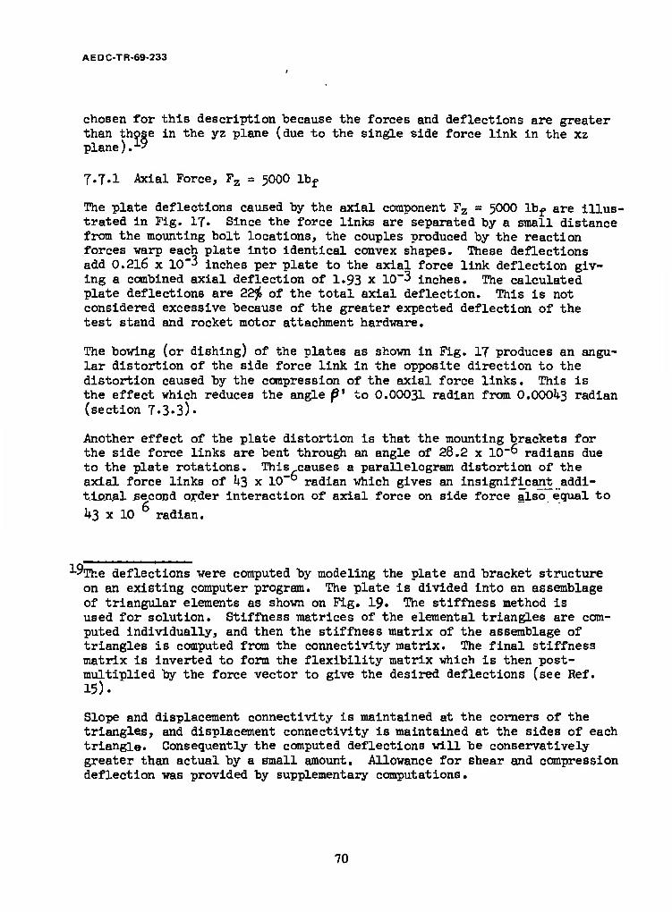
AEDC-TR-69-233
chosen for this description because the forces and deflections are greater than th< plane). ■
7.7.1 Axial Force, Fz = 500O lbf
than those in the yz plane (due to the single side force link in the xz
The plate deflections caused by the axial component Fz - 5000 lbf are illus- trated in Fig. 17. Since the force links are separated by a small distance from the mounting bolt locations, the couples produced by the reaction forces warp each plate into identical convex shapes. These deflections add 0.216 x 10"3 inches per plate to the axial force link deflection giv- ing a combined axial deflection of I.93 x 10"3 inches. The calculated plate deflections are 22$ of the total axial deflection. This is not considered excessive because of the greater expected deflection of the test stand and rocket motor attachment hardware.
The bowing (or dishing) of the plates as shown in Fig. 17 produces an angu- lar distortion of the side force link in the opposite direction to the distortion caused by the compression of the axial force links. This is the effect which reduces the angle f* to 0.00031 radian from O.OOOU3 radian (section 7.3«3)-
Another effect of the plate distortion is that the mounting brackets for the side force links are bent through an angle of 28.2 x 10"° radians due to the plate rotations. This causes a parallelogram distortion of the axial force links of 1+3 x 10"° radian which gives an insignificant addi- tional second order interaction of axial force on side force also equal to
k3 x 10 radian.
■*-°The deflections were computed by modeling the plate and bracket structure on an existing computer program. The plate is divided into an assemblage of triangular elements as shown on Fig. 19. The stiffness method is used for solution. Stiffness matrices of the elemental triangles are com- puted individually, and then the stiffness matrix of the assemblage of triangles is computed from the connectivity matrix. The final stiffness matrix is inverted to form the flexibility matrix which is then post- multiplied by the force vector to give the desired deflections (see Ref. 15).
Slope and displacement connectivity is maintained at the corners of the triangles, and displacement connectivity is maintained at the sides of each triangle. Consequently the computed deflections will be conservatively greater than actual by a small amount. Allowance for shear and compression deflection was provided by supplementary computations.
70

AEDC-TR-69-233
Y AXIS
OUNTING BOLT LOCATIONS
AXIAL FORCE LINK LOCATIONS
BASE PLATE BRACKET LOCATION
FIGURE 19. TRIANGULAR ELEMENTS FOR PLATE DEFLECTION ANALYSIS
71

AEDC-TR-69-233
7.7.2 Side Force, Fx - 1000 lbf
The distortional effect of the side force component, Fx = 1000 lb, is illustrated in Fig. 18. The force Fx is shown acting on a rigid bracket so that the line of action is in the xy plane. This conceptual loading gives essentially zero force in the three axial force measuring links, and the force in the side force link is equal to Ity = 1000 lbf (except for slight flexural redundancy).
The reaction force Ffy applied to the brackets warps the plates slightly by an angle of 39.5 x 10~° radians in the xz plane. This increases the lateral translation of one plate relative to the other by 0.235 x 10"3 inches. This is 12$ of the total lateral translation (I.96 x 10"3 inch) including the compressive deflection of the lateral force link and the bracket deflection.
The deflection of the side force mounting bracket (bending, shear, and compression) is calculated to be 0.111 x 10"3 inches per bracket which for both brackets amounts to 11.h<^ of the total deflection. Other dis- tortions are negligible for this mode of loading. For example, the angu- lar distortion^of the side force link due to this bracket distortion is only 3*8 x 10"° radians.
7.7.3 Pitching Moment, My = 12,500 in.lb
The contribution of the two plates to the overall deflection is completed by considering distortions due to a pure pitching moment, My = 12,000 in.lb, (This moment arises from the location of the 1000 lb lateral force at a distance of 12.5 inches from the reference plane).
The largest displacement computed as a result of plate dislocation is a lateral displacement of 58»2 x 10"" inches, which gives a parallelogram distortion of the axial force links of 13 x 10"° radians. Consequently the effect of the pitching and yawing moments on plate distortion is negligible.
7.7.1+ Flexural Moments caused by Plate and Bracket Distortion
The angular distortions of the plates and mounting brackets discussed in the preceding sections have another effect besides distortion of the force link geometry. These angular distortions change the boundary conditions at the flexure pivots and thereby introduce small extraneous moments.
The effect of the 5000 lb axial force component (in Fig. 16) is that the algebraic sum of plate rotation plus sidesway. bends the axial flexures algebraic sum or plate rotation plus sxaesway oenas t 89.9 x 10"° radians on one end and 3.9 x 10"° radians on the other end.
72

AEDC-TR-69-233
The result of the difference in moments at the ends of the axial force links isAFy= 0.233 lb in the y direction. This causes a change in the vector angle of O.233/5OOO = 1+7.7 x 10"" radian. This negligible value is classified as a first order interaction of axial force on side force because AFy is a linear function of the axial force component.
A similar bending of the flexures on the side force link IA occurs from rotation of the plate and side force link bracket in the xz plane. This bending reduces the restoring moment caused by axial deflection of the axial force links, and the net effect is to reduce the small restoring force due to the side force link. The reduction amounts to 0.002$ of 5000 lb and is not significant.
The same type of analysis was carried out for Fig. 17 where the side force is Fx = 1000 lb. Here the angular deflections due to plate distortions are less than for the previous case and may be ignored. The calculated angular deflection due to bracket bending is equal to 51.0 x 10"° radians which is also insignificant.
The preceding comments also apply to the effect of a pure pitching moment, My = 12,500 in. lb. Again the angular deflections are so small that the forces caused by bending of the flexures are insignificant.
73

AEDC-TR-69-233
SECTION VIII CALIBRATION AND DATA REDUCTION
The calibration of a vector thrust load cell and the reduction of cali- bration and test data are accomplished in accordance with general methods and theory applicable to existing six-component rocket engine test stands. The vector load cell structure is essentially statically determinate, and the effects of deflection under load are negligible relative to the accur- acies needed for most types of rocket motor testing. The structure and transduction elements have essentially linear and repeatable character- istics, and therefore are readily analyzed by conventional algebraic techniques. The following analysis discusses theory and technique of calibration for the orthogonal tripod geometry.
8.1 BASIC EQUATIONS
Based upon the assumption that the structure is statically determinate and that the force links are perfectly aligned, a set of six equations will be written by summation of forces and moments in the orthogonal directions. These equations describe the six generalized external force and moment com- ponents of the external force vector in terms of the force link reaction forces. They are referred to the cartesian coordinate system originating at the balance reference plane (Fig. 6).
This set of equations will be systematically expanded in stages to account for interaction terms, and will finally result in a general six-by-six matrix of data reduction equations (equation U3).
Fz* = Rx + R2 + R3 (Axial Force)
Fx' = Rij (Yaw Force)
Fy» - -(R5 + Rg) (Pitch Force)
(l repeated) M2' = RcXc + Rgxg (Roll Moment)
Mx' = Riyi + R2y2 + R3X3 (Pitching Moment)
My' = -R2X2- R3X0 (Yaw Moment)
74

AEDC-TR-69-233
The thrust vector intercept with the reference plane is given by:
- Mv
y = _i
(32)
These forces and moments are expressed in matrix form as (terms omitted are zero): (F'} = [AHA}
V] l i 1 1 Rl
v/ 1 \ *2
yl -1 -1
vR3
*«'( x5 x6 ) Ru
V] yi y2 *3 / R5
V/ -X2 "x3 \ «6
(33)
The preceding equations are solved for the individual force link reactions. LThese reaction forces are" given in the following equations for reference:
R_ = h. + £ ^c 1 3 3 r
R -Ü R2" 3 3r rVT (Balance Reference Radius)
R .i 3 3 3r tf^T
r = 5"
yx = r
R, = F 4 X y2 ■ y3 - - 1
R =!y. 5 2
- Mz
XU+X5
v a -x~ -r vT X3 *2 2
R6 = üz + Mz
(30
V*5l
75

A EDC-TR -69-233
Since the data is recorded as analog electrical voltages which are propor- tional to the force link reactions, the Rj in the first six equations may be writ- ten in terms of the individual electrical outputs Ej and proportionality constants C^ (again assuming no interaction effects):
i - 1, 2, (35)
Substituting equations 35 in equations 33 gives the unconnected external forces as a function of the force link electrical output voltages (terms omitted are zero).
{F? ~ [S'KE}
V C-L C2 C3
*> «/ *x /
F ' I
vl yici y2c2 y3c3
Vj -~x.2^2' ~x3^3
%
-c5 '% X5C5 X6C6
*2
E3
E5 E6
(36)
8.2 FLEXURE STIFFNESS
We will now develop a similar set of equations which will account for re- storing forces and moments caused by stiffness of flexures in beading and torsion. When the balance deflects under load, rotations of flexure pivots produce restoring moments in directions opposite to the rotations. These moments,acting through the radius arms of the force links, produce restor- ing forces.
If the external forces and moments were computed as a function of reaction forces Rj^ given in equation 36, the results would be in error by the amount of the restoring forces and moments. Such a computation would not normally be made because force links are calibrated as part of the assembled balance, and the calibration constants obtained account for reduction of sensitivity caused by flexure stiffness. The purpose of this discussion is to show how the restoring forces and moments affect the calibration of the balance, and to this end the redundant flexural forces and moments may be simply expressed in terms of fractional redundancy (as discussed in Section -7.4.1).
76

AEDC-TR-69-233
AFZ = Fz» Dz= Dz (RX + Rg + R3)
AFX " V Dx * Dx < V
*Fy = V Dy = ^ ("R5 -R6 ) (3T)
**■ "V ^z = Duiz (1*5*5 -R^)
^Mx - V Vox - %x (Rm + R2y2 + «3/3)
AMy = My' I^y = E^jy (-R2X2-R3X3)
An alternative method for expressing the redundant moments is to use the locations of the elastic axes of the individual -force links(as defined in Section 7.k*2), In terms of the deviations of elastic axes from the geometrical axes, the restoring moments are:
AMZ = <R5Ax5 + R6Ax6)
4MX = (\ZLyj_ + BQAy2 + «3^3) (38)
AMy = (-R2Axg - R3AK3)
As discussed in section J.k.3 the cross-coupling caused by the combination of flexure stiffness and the small amounts of asymmetry in the balance design are insignificant. Therefore," only the terms representing reduction of sensitivity from equations 37 and 38 are included in the following equations. The terms omitted in the matrix are zero and represent negli- gible cross-coupling constants.
77

AEDC-TR-69-233
F
M
M
M
{AF\ =IMKR}
D D D z z z
y y
A x5 ^xg
R2
(39)
8.3 MISALIGNMENT INTERACTIONS
As the next step in the development of the system equations, the first order interactions caused by force link misalignment are obtained. This is accomplished by multiplying each of the reaction forces R± at the individual load links by three direction cosines to resolve these re- action forces into Rx, Ry, and Rz components.
Since direction cosines relative to coordinate axes that are parallel to the force links are essentially unity, the error forces due to misalign- ment corresponding to these cosines are zero. The terms representing these commonly called "cosine errors" are indicated by zeros in the following matrix of misalignment interactions. The terms which are not zero repre- sent true first order interaction (cross-coupling) between the generalized external force and moment components. Note that the zeros must occupy the same positions in the matrix as the uncorrected constants in Equation 33« The uncorrected equations (Eq. 33) will later be added to the following misalignment equations along with the restoring forces (Eqns. 39)»
A force diagram showing the resolution of the reaction force for the L^ force link is illustrated in Figure 20. In this diagram the angles o^, 0 4, and 1 i± represent the direction angles of the line-of-action of the axial component R^ for this force link. The shear force component due to flexural restoring moments is covered by the preceeding equations (39)- In this part of the analysis the flexures are assumed to be perfect pivots such that the line-of-action connects the two pivot points on opposite sides of the force link. The misalignment is greatly exaggerated in Fig. 20 for clarity.
78

AEDC-TR-69-233
(SUBSCRIPTS INDICATING THE NUMBER OF THE FORCE LINK ARE OMITTED FOR VISUAL CLARITY).
Y AXIS
Z AXIS
FIGURE 20. FORCE LINK REACTION COMPONENTS AND DIRECTION ANGLES
79

AEDCTR-69-233
In the following equations o( ±, ß ±} and JT< are the direction cosines corresponding to the direction angles Aj., 2i( and y t. The location parameters xj_, y^, and z^ are the locations of the flexure pivot points connected to the floating plate of the balance. 1
The equations expressing interaction due to misalignment are:
AF2
4F,
AT*
14M,
AMV
■ I
"W. L
fa'3B = [B]{R}
0 0 0 V4 y5 *6 Hi
*L «2 «3 0 *5 *6 j R2
A H A A 0 0 i R3
+ 0 ^2 -/2X2
"5*3 Ax3 7*1 0 0 \ RU
Azi /2Z2 Az3 0 *5y5 V&6 I "*
5izi 0C2z2 *3Z3 ->w -y5x5 -*6X6 1 R6 B
(ho)
8.4 INTERACTIONS DUE TO MOMENT AND SHEAR FORCE SENSITIVITY
Other first order interactions result from the sensitivities of force cells to the restoring shear forces, moments, and torques caused by flexural redundancy. These redundant forces and moments give rise to error voltages within the force links (as discussed in Section 7*5) which are accounted for by the off-diagonal coefficients in the following matrix relating the load cell output voltages E^ to the reaction forces Rj_. The coefficients on the main diagonal are the same as those previously given in Equations
35* ^i"= ^i^i*
"TThe subscript B representing the floating plate of the balance was omitted in the location parameters for simplicity.
80

AEDC-TR-69-233
{R} = [C]{E}
R.
R,
'11
'21
"31
\l
:51 :6l
'12
'22
'32
'52
:62
313 cl4 c15 cl6
'23
333
^3
:53
:63
J24
'3^
z6k
'25
'35
3*5
'55
:65
'26
'36
\6
356
:66
Ei
E„
E, (hi)
8.5 SYSTEM EQUATIONS INCLUDING FIRST ORDER INTERACTIONS
We have at this point obtained expressions for error forces {jAFj as a function of flexural redundancy and force link misalignment, which are
4derived from the first order linear elastic and geometric properties of the balance. Also, we have stated an expression for output voltages as. a function of force link reaction forces which accounts for the effects of force cell sensitivity to redundant forces and moments.
The equations for the external force vector £äF} as a function of the reaction forces {R} may be obtained by adding the redundancy and mis- alignment error force expression to the basic equations £F'} = EA3{RJ
{F} = {F'} +f*Fjm +{AF}B
{Fj =([Al + [MJ + TB] )£R}
fF} =[N]fR}
[N] = [A] + [M] + TB]
or
where
(hz)
The matrices of coefficients within the parentheses are summed to give the matrix [NJ. Equation kl is substituted in this equation to give the exter- nal force vector as a function of the vector of six output voltages {E} and a six-by-six matrix of calibration coefficients [S 3 .
81

AEDC-TR-69-233
or
{F} =[.]lc]{i)
{Fj =[S]{E}
where
[8] ' ■MM In expanded form.:
( F \ I z 1
Sll S12 S13 S1U S15
S16 [El \ F 1 1 1
S21 S22 S23 s2h S25 326 %
\Fy\
s3l s32 s33 s3k s35 s36 E3
|Z| sUl %2 sk3 skk SU5 s46 *4
lMxl S51 S52 s53 s5U S55 s56 E5
K s6l S62 s63 S6U s65 s66 ^
C»3)
This matrix of calibration coefficients QsJ does not account for interactions due to deflection of the center of gravity of the rocket engine. Also it does not account for any higher order interactions which are assumed to be negligible in this analysis.
8.6 CALIBRATIONS
In the preceding analysis we have shown how the force link sensitivities and first order interactions lead to six linear equations which express the external forces and moments as a function of the recorded voltages. The constants in these equations could theoretically be calculated from knowledge of the structural parameters and misalignment angles of the force links and from six-component calibrations performed on individual force cells removed from the balance. However, it is usually more prac- tical and more convincing to determine these coefficients from calibra- tion of the assembled balance by the systematic application of external forces with known magnitudes and lines-of-action. The preferred method is to use a precision loading mechanism which allows the balance to be realigned during application of loads (referred to as a Type I calibra- tion). This insures that deflections of the balance or loading mechanism do not distort the alignment of the calibration loads. These calibration loads are applied one at a time to evaluate first order interactions, and
82

AEDC TR-69-233
in combinations to evaluate second order interactions. The calibration coefficients so determined provide the basis for test data reduction or for further calibrations on the test stand (referred to as Type II and Type III calibrations).
In the Type I calibration, the calibration constants are established relative to alignment points on the balance proper; therefore dimensions on the rocket motor and its mounting supports are referenced to the load cell coordinate system. This can be accomplished by assembly and alignment of the motor to the balance, using optical and mechanical measurement techniques, prior to installation on the test stand. Further calibration on the test stand (Type III calibration) will (l) verify the calibration coefficients representing force link sensitivity (as affected by flexural redundancy), (2) evaluate the effect of propellent coupling interactions (unless the prior calibration had been performed with propellant compen- sators attached, a recommended procedure), and (3) evaluate other effects such as shift in the center of gravity22 of the motor mass due to test stand and balance deflections.
The second alternative is a complete calibration on the test stand (Type II calibration) including the evaluation of interaction terms. This is the established procedure for test stand calibration wherein each of six individual equations in the calibration matrix (Eq. 1*3) is repeated six times to yield 36 equations in 36 unknowre or six, six-by-six matrices (Ref. l). A coordinate reference axis is thereby established relative to the positions and directions of the calibration loads. Using this method it is necessary to insure that the accuracy of location and the direction of these calibration loads are adequate for the desired accuracy of the particular test.
22 The shift in center of gravity might be difficult to evaluate on a test cell such as J-3 because the calibration loads are reacted by the supporting structure and thereby have less influence on test stand deflections. If this effect were significant, it could perhaps be more accurately evaluated by experimentally determining the natural frequencies of oscillation of the rocket motor in the test stand, and from this information and know- ledge of the inertial characteristics of the rocket engine (or a special test mass), the combined stiffness matrix of the balance and test stand could be back-calculated. Since this procedure only involves inertial forces it avoids the need for the application of calibration forces which would go directly to ground.
'83

AEDC-TR-69-233
One conclusion presented as a result of this study is that the interactions established in the Type I calibration on a special rig will be entirely repeatable on the test stand, and that any uncertainty in this repeatability will be less than the uncertainty of the effect of changes in the line-of- action of the calibration loads from test stand deflection in the Type II calibrations. Consequently, a combination of Type I calibration and a mod- ification of the Type II calibration referred to as a Type III calibration is applicable to the vector thrust cell.
The purpose of the Type III calibration is to evaluate properties of the balance which are most non-repeatable. We may be confident that the kine- matic and elastic properties of the balance will not change with time unless the balance has been over-loaded. However, verification of transducer pro- perties (namely the force cell sensitivities C^) in the test cell environment is Justified. This may be accomplished by application of calibration loads of accurately known magnitude. Precise direction and location of these loads are not critical within this concept because the cosine errors are negligible and the interactions and electrical centers have already been determined in the Type I calibrations. The constants to be evaluated in the Type III calibration occupy the same position in the following calibra-
tion matrix [Sjas the C^ coefficients in the basic equations given in matrix form (equations 36). The other coefficients are omitted to emphasize the terms which are to be evaluated in the Type III calibration. These omitted coefficients represent the S.. first order interaction terms previously es- tablished in the Type I calibration. The electrical centers of the force links yp y2> and y» and Xr and xg are combined location and interaction terms from the Type I calibration. The constants to be evaluated in the Type III calibration are given in the following equations:
{F} = [S]{E!
F..
M.
M.
M„
sll >12 '13 s2k
D35
-x5S35
s36
"X6S36
jrisll Y2^ y3S13
'xlsll "X2S12 "X3S13 J \
%
E3
EU
E5
E6
(MO
Since there are six constants to be established (S^, S^g, siv S2i, S^c S36) six independent equations are needed. Referring to the matrix*of equations U3, the first equation for axial force contains three of the
84

AEDC-TR-69-233
unknown constants to "be determined, S-^, S^2, and S-,.,, plus three known constants, S]^, S^c, and S^g, which have already been evaluated in the Type I•calibration, i.e.
Fz - SUE! + S12E2 + S13E3 + SlkEk + S^ + Sl6E6 (45)
To evaluate the three unknown interaction constants, we have to repeat the loading three times in such a way as to insure three independent equations in the three unknowns.
One way of accomplishing this is to apply the same magnitude of Fz parallel to the z axis at three separate and non-colinear points in a plane parallel to the xy plane. This gives the three following equations involving the magnitude of the applied calibration force and the measured electrical output voltages from the three axial force sensors (L]_, IKJ, and Lo).
Fzl - sli En + s12 E12 + s13 Ei3 + <*U E.U + si5
El5 + S16 E 16)
Fz2 - Su E21 + S12 E22 + S13 E23 + (Slk E22; + S^ E^ + S^ E 2ß) (U6)
F*3 " sll E3l + S12 E32 + S13 E33 + (S1U E3^ + S15 E35 + S16 E 36>
Expressed in matrix from these equations are:
to " [EXS} +(P*} "zll
rz2
?z3,
E 11 =•12 E
E. 21 E 22 E.
13
23
=•31 ^32 Ec =33
(sll) (slk Elfc + sl5 E15 + sl6 El6]
(sl2>+JsiU E2fc + S15 E25 + sl6 E26
[hk E3^ + S15 E35 + sl6 E36J s13 v. -v
(hi)
These equations can be solved for the unknown S-Q, S^and Sjo coefficients hy inversion of the [E] matrix:
{s} . M-i(f,j - {P-jj (1.8)
Note that it is not necessary to know the location of the applied forces; however, it is important that the forces be applied at different locations not on a straight line so that the equations are independent and the [E]
matrix is non-singular.
85

A EDC-TR -69-233
In this type of loading the interactions expressed by the sum of the products (Si^ E1it + S^e E^c + S^g E^) are negligible and could be ignored. This is true because the coefficients Sij,, S^,-, S^g are small. Also, the voltages E^ , E15>, an^ El6 v*11 De small because the directioi of loading is normal to the side force links L^, Le, and Lg.
If the calibration loads are applied directly over the electrical centers of the axial force links (which are in the neighborhood of 0.002 inch from the geometrical centers), two of the three outputs will be zero, and the output of the third will yield the ratio of the calibration load to the applied load. This is expressed by the following equations:
Fzi = Sn Eu + 0 +0
FZ2 - 0 + Si2 E22 + 0 (1*9)
FZ3 =0 +0 + S-L3 E33
Similarly the coefficients expressing sensitivity to side forces are evaluated by equations 50.
Px = S2k E2
Fyl = s35 E15 + s36 El6 <50)
Fy2 = s35 E25 + s36 ^6
The Fx and Fy loads should be applied in the vicinity of the electrical centers to avoid errors from first order interactions of pitching or yaw- ing moments on side forces. Again, precise location and alignment of these loads is not important. Here also the interaction terms established in t he Type I calibration may be omitted unless it is impractical to place the loads in the vicinity of the electrical centers.
The preceding discussion concerned the application of single loads at different points, one at a time, to illustrate the basic principles of determining the sensitivity constants. In actual practice the axial sensitivity constants can be determined by application of combinations of loads. Three loads can be applied outside of the balance diameter simultaneously such that the resultant of these loads is parallel to the z axis and is located within the basic equilateral triangle of the axial force sensors. It is undesirable to allow the resultant to fall outside of this triangle because this puts one of the axial force cells in tension, a condition which is not expected during an actual test firing.
86

AEDC TR-69-233
The magnitudes of the three calibration loads are varied such that the re- sultant is increased in steps up to the maximum value of reaction force expected for each individual force cell during the test firings. The ratios of the applied loads should be maintained constant so that the location of the resultant does not change during this incremental loading. By this method, output voltage vs. load can be plotted for each axial force sensor, for each of three positions of resultant load. Then, linearity and hysteresis can be evaluated and data points for each resul- tant load position used to obtain a least squares fit straight line.
The slopes of these three straight lines Q^, i = 1, 2, 3, J = 1, 2, 3 are entered into Equations k"J (with the interaction terms omitted as be- ing negligible) normalized by dividing through by the applied forces. In matrix form this is expressed by:
1 } *L1 %.2 Q13
(= 021 «22 Q23
1) = Q31 a32 Q33
Sll
'12
'13.
fel)
After inversion, the desired coefficients S-j, S-p, S.,_ are given by:
Sll
312
313
M'1 1
1
$2)
If it is not practicable to maintain the resultant of the three calibration loads in a fixed position, an alternative scheme of data reduction can be used. By this second method the calibration constants are evaluated at each load level and a weighted average used for the final value of the calibration constants. A sample procedure is to apply the loads as follows:
87

AEDC-TR-69-233
Force Link
Combined Load No.l
Combined Load No.2
Combined Load No.3 Data Reduction
Rl
R3
25*'
<5*
<5*
<5*
25*
<5*
.<5*
<5*
25*
Calculate S-^, S-|_2> S-^o,
for increment No. 1 (25*), (Sy^
Rl
R2
R3
50*
<10*
<10*
<io*
50*
<10*
<10*
<10*
50*
Calculate S^, S^, S10, for increment No. 2 (50*), (SltJ)2
Rl
R3
75*
<15*
<15*
<15*
75*
<15*
<15*
<15*
75*
Calculate S^, S12, S]^ for increment No. 3 (75*), (Sj^jjg
Rl
R2
R3
100*
<20*
<20*
<20*
100*
<20*
<20*
<20*
10056
Calculate S-^, &j_2* S]_o for increment No. 4 fioo*), (slä)k
The values of the sensitivity constants determined can be weighted accord- ing to the fraction of time expected at those data points during the test firing. For the usual tests where resonance caused oscillations are negli- gibel most of the weight will be attached to the constants determined in the vicinity of the nominal thrust level. This weighted average is expressed as:
S = Gl (sll)l + 02(811)2 + G3(sll^ + G4(Bil)if (53)
Gi + G2 + G3 + GI4.
The parameters G-, and (S^L are the weighting numbers and sensitivity con- stants established at the 25$, 50$, 75* and 100* force levels. (If all G^^ = 1, this is an arithmetic average).
23 For example, a set of external forces parallel to the z axis is applied so that Ri is 25* of the full scale value (nominally 25* of 1666 lb). Restrict- ing R2 and R3 to less than 5* of full scale will avoid the possibility of ill-conditioned equations.
88

AEDC-TR-69-233
8.7 AXIAL THRUST READOUT
It is important to be able to continuously monitor thrust during rocket engine test firings. Since the axial thrust component F is the sum of three force link reactions a simple circuit (shown in Fig. 2l) using a summing amplifier will give a continuous on-line indication of axial thrust. The summing circuit will solve the first of equations kk (repeated here):
Fz = Sn Ei + S12 E2 + S13 E3 (UU-1 repeated)
In this circuit the potentiometers are adjusted proportional to the cali- bration constants S,,, S±2> an(* ^13 ^° 8^ve the correct weight to each output voltage E]_, Eg and E?:
89

A EDC-TR -69-233
FEEDBACK RESISTOR
Wi 1
SUMMING AMPLIFIER
AAA» ■
POWER STRAIN SUMMING SUPPLIES GAGE
BRIDGES POTENTIOMETERS RESISTORS
SUMMING AND FEEDBACK RESISTORS ARE 100, OOO Jl EACH
POTENTIOMETERS ARE lO.OOOÜEACH
BRIDGE RESISTANCE, 120fl EACH
FIGURE 21. ANALOG SUMMATION OF AXIAL THRUST
90

AEDC-TR -69-233
SECTION IX PROPELLANT COMPENSATOR
9.1 GENERAL DISCUSSION
This general discussion of propellant plumbing problems related to rocket engine test stands will serve as background for a discussion of a propellant compensator design applicable to the vector thrust cell concept.
Propellant lines which supply fuel and oxidizer to liquid propellant rocket engines tested on multi-component force balances represent a significant factor in the performance of the test stand. It is probably true that spurious forces introduced into the test stand by the propellant lines are the greatest limitation on accuracy. This is particularly true in regard to the accuracy of the location and angle of the measured thrust vector.
One of the adverse effects of the plumbing connections is stiffness which adds to the restoring forces from the flexures. This creates additional first order interactions that further complicate inherently complex calibration and data reduction theory and procedure.
If interactions attributable to plumbing were linear and repeatable, and if they could be adequately accounted for by comprehensive six- component calibrations conducted in the test cell with plumbing connections completed, they would theoretically not affect accuracy. However, it is common experience that assemblages of pipes, flexible tubing, bellows couplings, and braided hose have hysteresis and non- repeatability of much greater magnitude than the highly precise load cells and flexures which comprise the primary elastic elements of the test stand. This is particularly true for liquid rocket engines which operate at high values of chamber pressure and propellant pressure. Propellant tubes sized to withstand these high pressures are stiffer and more non-repeatable in direct proportion to the pressure.
A formed or welded bellows when stressed within the elastic range by internal hydraulic pressure or by deflection of the test stand under load should have minimal hysteresis and non-repeatability. In appli- cations where high precision is required these elements are utilized to the exclusion of other types of flexible tubing such as non- metallic or braided metal hose. If elastic metal bellows assemblies are connected to the test stand with joints that prevent sliding or pivoting friction at the connection, the sources of non-repeatability in the connections should be reducible to a level consistent with the requirements of a high precision force balance.
91

AEDC-TR-69-233
If the bellows and tubing assemblies are free of hysteresis the remaining source of non-repeatability is the test stand structure itself. The floating plate of the balance, suspended on flexured force links and the fixed portion which is ultimately connected to inertial ground must either be extremely rigid so that deflec- tions are insignificant, or else these structural deflections must be linear and repeatable. Otherwise, repeatability would not be achieved for the variable force reactions at the propellant plumbing attachment points, or to a lesser degree at the flexure attachment points. These reaction forces should be proportional to the propellant plumbing deflections (bending, twisting, and extension) which are themselves proportional to deflection of the floating portion of the test stand. It can be seen that if the test stand structural components, either suspended or fixed to ground, undergo non-repeatable internal deflections the stiff- ness of the propellant plumbing will cause significant non-repeat- able reaction forces to be recorded during calibrations or test firings.
The next subject is the examination of the effects of temperature gradients within the test stand. Assume that the preceding require- ments have been accomplished so that the entire test stand including the propellant plumbing, suspended and fixed structural supports, and the load cells and flexure pivots behave in a repeatable linearly elastic manner when subjected to representative calibration loads. What are the effects of expansion and contraction caused by tempera- ture changes within the propellant connections and the test stand structure? Just prior to a test firing assume that the plumbing and structure have reached a stabilized temperature and the indivi- dual load cell electrical outputs have stabilized at their zero reference levels. Then at the valve-on signal, propellant valves open allowing fuel and oxidizer to surge through the propellant plumbing and then ignite and burn in the rocket combustion chamber. Heat from the combustion is conducted back through the suspended structure to the propellant connections and the load cell and flexure suspension points. If the propellant supply temperatures have been pre-conditioned to match the test cell ambient temperature, temperature gradients within the plumbing will not result from the flowing propellants. However, heat from combustion may be conducted back to the plumbing if the insulation between the engine and its supporting cradle is inadequate. Likewise, radiation from the ex- haust plume may, if not shielded, be a source of transient tempera- ture change.
Finally, heat which does soak back from the hot engine by conduction to the suspended thrust stand structure, (and eventually to plumbing connections, flexure pivots, and load cells) will cause the suspended
92

AEDC-TR-69-233
structure to expand relative to the fixed portion of the stand. One effect of this is misalignment of force links, with which we are not immediately concerned. However, this expansion will cause relative motion between the plumbing connections and the individual force cells, creating spurious reaction forces and moments at the propellant plumbing attachment points. These spurious forces are then sensed by the force cells and appear in the reduced data most noticably as perturbations in the sensitive location and direction components of the thrust vector. The effects of such temperature caused expansions (or contractions) are reduced by attention to details of insulation and radiation shielding, plumbing design, and plumbing location. By locating the propellant connections in proxi- mity to particular load cells, the overall expansion of the suspended structure between the load cells and the plumbing will be minimized for a given change of temperature. Close proximity of propellant couplings to force cells is one of the inherent advantages of the com- pact construction of the vector thrust cell concept.
Assuming we have achieved a test stand or vector thrust load cell design which is reasonably free of the aforementioned problem we are now left to consider forces caused by hydraulic pressure within the plumbing. The well known Bourdon tube effect causes a curved tube to straighten; consequently, if an arrangement of propellant tubes bent at various angles is required the bends must be made using thick rigid elbows. Also, flexibility must be achieved by using interconnected lengths of straight tubes or bellows assemblies. This flexibility allows the forces caused by hydraulic pressure to be cancelled by equal and opposed projected areas. One area acts against the projected area of the propellant inlet to the rocket engine manifold, and this is opposed by another equal area rigidly connected to the first by a tube, but flexibly connected to the propellant line anchor point.
Such an arrangement of tubes and flexible bellows at various angles gives some relief to static hydraulic pressure forces. The residual hydraulic forces which are transmitted to the load cells may be ex- tracted from the test data by obtaining calibration curves of force and moment components as a function of propellant inlet pressure. If these calibration curves are repeatable and if high frequency pressure surges do not exist during the periods of interest for test firings, the plumbing requirements applicable to a precise thrust vector measurement system would be satisfied.
The problem of hydraulic forces may be alleviated by a special pressure compensated bellows assembly, which insures that static hydraulic forces are cancelled by equally opposed projected areas. The residual forces may thus be minimized to the extent that moderate non-repeata- bility in calibration curves for pressure vs force become insignificant«
93
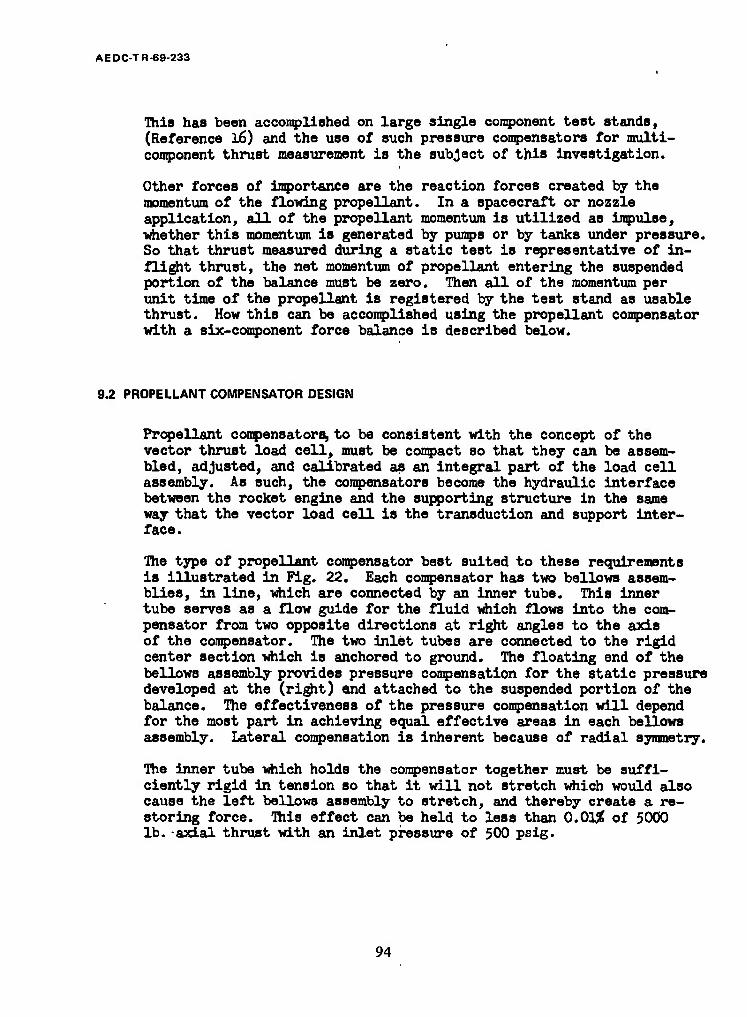
AEDC-TR-69-233
This has been accomplished on large single component test stands, (Reference l6) and the use of such pressure compensators for multi- component thrust measurement is the subject of this investigation.
Other forces of importance are the reaction forces created by the momentum of the flowing propellant. In a spacecraft or nozzle application, all of the propellant momentum is utilized as impulse, whether this momentum is generated by pumps or by tanks under pressure. So that thrust measured during a static test is representative of in- flight thrust, the net momentum of propellant entering the suspended portion of the balance must be zero. Then all of the momentum per unit time of the propellant is registered by the test stand as usable thrust. How this can be accomplished using the propellant compensator with a six-component force balance is described below.
9.2 PROPELLANT COMPENSATOR DESIGN
Propellant compensators, to be consistent with the concept of the vector thrust load cell, must be compact so that they can be assem- bled, adjusted, and calibrated as an integral part of the load cell assembly. As such, the compensators become the hydraulic interface between the rocket engine and the supporting structure in the same way that the vector load cell is the transduction and support inter- face.
The type of propellant compensator best suited to these requirements is illustrated in Fig. 22. Each compensator has two bellows assem- blies, in line, which are connected by an inner tube. This inner tube serves as a flow guide for the fluid which flows into the com- pensator from two opposite directions at right angles to the axis of the compensator. The two inlet tubes are connected to the rigid center section which is anchored to ground. The floating end of the bellows assembly provides pressure compensation for the static pressure developed at the (right) end attached to the suspended portion of the balance. The effectiveness of the pressure compensation will depend for the most part in achieving equal effective areas in each bellows assembly. Lateral compensation is inherent because of radial symmetry.
The inner tube which holds the compensator together must be suffi- ciently rigid in tension so that it will not stretch which would also cause the left bellows assembly to stretch, and thereby create a re- storing force. This effect can be held to less than 0.01# of 5000 lb.-axial thrust with an inlet pressure of 500 psig.
94

AEDC-TR-69-233
PROPELLANT INLET
MANIFOLD
lriuuuir
mniuiA
ATTACHED TO BASE PLATE OF BALANCE ATTACHED TO
ENGINE PLATE
FIGURE 22a. PROPELLANT COMPENSATOR, SECTION
95

AEDC TR-69-233
PROPELLANT COMPENSATOR
PROPELLANT INLET
FIGURE 22b. PROPELLANT COMPENSATOR, CONCEPTUAL INSTALLATION
96
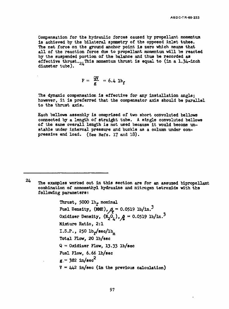
AEDC-TR-69-233
Compensation for the hydraulic forces caused by propellant momentum is achieved by the bilateral symmetry of the opposed inlet tubes. The net force on the ground anchor point is zero which means that all of the reaction force due to propellant momentum will be reacted by the suspended portion of the balance and thus be recorded as effective thrust.2,This momentum thrust is equal to (in a 1.34-inch diameter tube).
F = SS =6.4 lb- g f
The dynamic compensation is effective for any installation angle; however, it is preferred that the compensator axis should be parallel to the thrust axis.
Each bellows assembly is comprised of two short convoluted bellows connected by a length of straight tube. A single convoluted bellows of the same overall length is not used because it would become un- stable under internal pressure and buckle as a column under com- pressive end load. (See Refs. 17 and 18).
The examples worked out in this section are for an assumed bipropellant combination of monomethyl hydrazine and nitrogen tetroxLde with the following parameters:
Thrust, 5000 lbf nominal
Fuel Density, (MMH),p = 0.0519 lb/in.3
Oxidizer Density, (^2°L}*A " 0-°510 lb/in.3
Mixture Ratio, 2:1
I.S.P., 250 lbj/sec/^
Total Flow, 20 lb/sec
Q = Oxidizer Flow, 13-33 lb/sec
Fuel Flow, 6.66 lb/sec
g.= 382 in/sec
V = 442 in/sec (in the previous calculation)
97
AEDC TR-69-233
The assembly has basically five degrees of freedom, being some- what rigid in torsion. Flexibility in lateral translation is about three times that of axial translation, which very roughly compares with the ratio of lateral to axial flexibility of the basic balance design. The compensator uses a flow guide inner diameter of 1.34 inches and is designed for 500psig nominal pressure. This design has a redundancy of less than 0.0l£ in axial and lateral translation and pitch rotation referred to the stiffness of the basic balance design in these directions. Restoring moments are somewhat higher in yaw rotation (about 1/4$) due to the placement of the compensators on either side of the balance in the yaw plane. This redundancy can become negligible if the compensators are located within the balance rather than outboard. However, this increases balance size, weight, and perhaps complexity.
The torsional redundancy is greatest due to the relatively large torsional rigidity, being about 1.3%. Undoubtedly this value could be reduced by more extensive design analysis, but it is not con- sidered excessive in view of lack of emphasis on roll torque accuracy.
The selection of design parameters of a compensator is essen- tially a trade-off between low pressure drop and low stiffness. In general, low stiffness is aided by using smaller diameter bellows. This may be achieved without suffering excessive pressure drop because of the relatively short length of the compensators. Inlet and outlet plumbing connections may be increased to reduce pressure drop outside of the compensators.
The various parameters of the bellows and compensator assemblies are tabulated in Table EC for two nominal pressures (500 and 1000 pei^ and two diameters of inner flow guide (1.34" and 1.84"). The stiffness and redundancy parameters become larger as the pressure and diameter are increased. It is unlikely that it would be necessary to use the larger diameter because the pressure drop is not ex- cessive in the smaller unit.
Pressure drop through the compensator was conservatively estimated on the basis of twice the hydraulic head (V2). This allows for a right angle entrance and exit with 2g transition to larger tubing upstream and downstream of the compensator. With the pressure drop of 4-9 paid for the basic size, it would seem reasonable that a still smaller unit could be used, which would further reduce stiffness and redundancy.
Based upon the foregoing analysis, it appears reasonable that suit- able propellant compensators can be designed with a high probability of success without a trial and error development program. The re- dundancy of the compensators is sufficiently low that even with a hysteresis of 5% (typical for bellows assemblies), the net hysteresis seen by the balance would be less than 0.01$ for all modes except roll, which would be about 0.05^.
98

AEDC-TR-69-233
TABLE IX
BELLOWSx*"" AND COMPENSATOR ASSEMBLY PARAMETERS ,(25)
25
26
Material: Inconel 600
Internal Pressure (psig) Nominal Proof Distortion Burst Squirm
500 750
1000 1000<p<3CO0 1500
1000 1500 2000 2000<p<6000 3000
Inside Diameter (in) 1.48 2.00 1.48 2.00
Outside Diameter (in) 1.94 2.85 1.94 2.85
Wall Thickness (in) .010 .018 .014 .025
Pitch (in) .083 .15 .083 .15 Bellows Length 26 (in) .665 .90 .665 .90
Number of Convolutions 8 6 8 6 Length Between Eellows 2.0 2.0 2.0 2.0
Convolution Radius (in) .016 .030 .021 .037
Inside Diameter of Flow Guide (in) 1.34 1.84 1.34 1.84
Pressure Drop Through Assembly (NgO, ) psid 4-9 2.6 2.45 1.30
Redundancy of Compensator
DZ(S) .046 .077 .13 .21 D .092 .163 .26 .47 Dy .079 .14 .22 .39 D0x .005 .007 .014 .020
% .254 .42 .72 1.19
% 1.30 4.45 3.70 12.6
Spring Constant '
Kg (lh/in) 1,200 2,000 3,400 5,600
K -K (lb/in)
0x rad. K. (lb/in) m rad.
% (Win) F rad.
472
2,040
99,200
127,000
836
2,856
164,800
435,000
1,330
5,750
280,000
361,000
2,360
8,030
464,000
1230,000
Bellows data supplied by Gardener Bellows Co., Van Nuys, California.
Per bellows.
ZT Total for two propellant compensators per balance assembly.
99

AEDC-TR-69-233
SECTION X CONCLUSIONS
The analysis conducted during this study has established that the con- cept of a vector thrust load cell with an attached propellant compen- sator is capable of providing the general advantages of reduced on- site calibration effort, simplified alignment to the rocket engine, and improved accuracy for liquid propellant rocket engines. Although no exper- imental evaluations were performed on the concepts discussed, the analy- tical work used standard methods of static and dynamic structural analysis based upon actual test data for flexures, force cells, and strain gages. This structural and transduction analysis was conducted in depth for a basic workable design to the extent that all conceivable anomalies were quantitatively evaluated. Since this basic design differs from standard practice primarily in geometrical arrangements of force links and in the parameters defining the flexures and force cells, we are confident that the results are realistic and practicable.
Because of the unorthodox force link geometries, short force link lengths, and stiff and basically uncomplicated flexures and force cells, it is appreciated that there may be instinctive reservations by those contem- plating use of such vector thrust load cells. Hopefully this analysis will be sufficient to convince prospective users that the advantages gained in the form of increased rigidity of force links and a more com- pact structure overcomes the seemingly remote placement of the force links from the center of mass and the motor nozzle. The natural fre- quencies calculated are higher, and the interactions are less than those observed for most conventional test stands. Since these advantages are combined with the convenience of being able to calibrate the vector thrust cell and align it to the engine remotely from the test stand, these con- cepts are expected to make a substantial improvement in the art of multi- component thrust measurement.
100

AEOCTR-69-233
SECTION XI RECOMMENDATIONS
In view of the expressed advantages of the concepts studied during this program, extension and development of this work is recommended. Several alternative courses of action are possible depending on AEDC requirements.
1. The most direct extension of this work would be an experimental evaluation of the half-scale model constructed during this program. Resolution, inter- actions, and deflections would be determined by precise six-component calibrations on a wind tunnel balance calibration fixture. The results of this would be used to predict the accuracy of the basic design during representative rocket engine test applications.
2. A full scale model of the basic design including propellant compensators for applicable pressure and flow ranges could be constructed. This would be a working model designed for rocket engine testing. The balance and propellant couplings would be evaluated by exhaustive calibrations, and subsequent realignment of force links would be per- formed if necessary. These units would be delivered to AEDC upon completion.
3. Based upon evaluation of the trade-offs expressed for the alternative geometric configurations, the pre- ceding program would be conducted for either the reflected geometry or the torsion bar modification.
101
AEDC-TR-69-233
REFERENCES
1. Davis, R. L. and Spicer, L. M. "Thrust Vector Determination of a Fixed Nozzle Engine in a Rigid Horizontal Six-Component Thrust Stand." AIAA Publication CP-12. American Institute of Aeronautics and Astronautics. 1965, p. 260-274.
2. Postma, R. W. "Pulse Thrust Measuring Transducer." Rocketdyne Division of North American Rockwell Corporation. R-6044 (AD 459068). January 1965.
3- Crosswy, F. L. and Kalb, H. VT. "Investigation of Dynamic Rocket Thrust Measurement Techniques." AEDC-TR-67-202. November 1967.
h. Crosswy, F. L. and Kalb, H. T. "Dynamic Compensation and Force Calibration Techniques for a Static and Dynamic Thrust Measurement System." ABDC-TR-68-202, November 1968.
5- Crosswy, F. L. and Kalb, H. T. "Performance of a Dynamically Compensated Load Cell Force Measurement System." AEDC-TR-68-211. November 1968.
6. Hurty, W. C. and Rubenstein, M. F. Dynamics of Structures. Prentice-Hall Inc., 1964.
7. Crede, C. B. Vibration and Shock Isolation, John Wiley and Sons Inc., New York, 1951.
8. Taskit Measurement Systems Components. Document No. R-451 (1273). Task Corporation, 1009 E. Vermont Ave., Anaheim, California.
9. Tracy, R. R. "Wind Tunnel Sting Balances." Presented at the Meeting of the Western Regional Strain Gage Committee, San Francisco, May 11 and 12, 1961.
10. Tracy, R. R. "Elastic Pivots in Force Resolution Systems," Report R-768, Task Corporation, Anaheim, California, Presented at the 1965 SESA Spring Meeting, Denver, Colorado, May 5-7, 1965.
11. Eastman, F. S. "Flexure Pivots to Replace Knife Edges and Ball Bearings." University of Washington Bulletin No. 86. Seattle, Washington, November 1935.
12. lindgren, B. W. and McElrath, G. W. Introduction to Probability and Statistics. The MacMillan Co., 1969.
102

AEDC-TR-69-233
13« Davie, R. P. "Wind Tunnel Models." NATO Advisory Group for Aeronautical Research and Development. Report 19 (AD 116950). August 1956.
1^. Webb, R. D. "The Unique Performance Potential of a New Load Cell." The Society of Aeronautical Weight Engineers. Inc.. Tech. Paper No. 583. Hay 1966.
15- Rubenstein, M. P. Matrix Computer Analysis of Structures. Prentice Hall Inc., 1966.
16. Daniels, C. M. "Designing for Duct Flexibility with Bellows Joints," Machine Design. 51. 146-155. October 1959.
17. Daniels, C. M. "Bellows Design for Aerospace Vehicles," Aerospace Vehicle Cryogenic Ducting. SAE ARP 735. Section 5.4. August, 1966.
18. Newland, D. E. "Buckling of Double Bellows Expansion Joints Under Internal Pressure," Journal of Mechanical Engineering Science. Vol. 6. No. 5. 1964.
103

UNCLASSIFIED Security Classification
DOCUMENT CONTROL DATA -R&D (Security classification ol title, body ol abstract and Indexing annotation must be entered »hen the overall report la classified)
1. ORIGINATING ACTIVITY (Corporate author)
Rocketdyne, a Division of North American Rockwell Corporation, 6633 Canoga Avenue Canoga Park, California 91304
M.REPORT SECURITY CLASSIFICATION
UNCLASSIFIED 2b. CROUP
N/A 3. REPORT TITLE
VECTOR THRUST LOAD CELL FEASIBILITY STUDY
«. PESCR1PTIVE NOTES (Type ol report and inclusive dates)
April 1968 - June 1969 - Final Report B. AUTHORIS) (Pint name, middle Initial, leat name)
R. W. Postma
6. REPORT DATE
December 1969 SS. CONTRACT OR GRANT NO. F40600-68-C-0004
b. PROJECT NO. 4344
<=■ Task 36
„. Program Element 65701F
7B. TOTAL NO. OF PAGES
111 7b. NO. OF REFS
18 3a. ORIGINATOR'S REPORT NUMBER(S)
R-7819
Bb. OTHER REPORT NOISI (Any other numbers that may be assigned fhis report)
AEDC-TR-69-233 10. DISTRIBUTION STATEMENT
This document has been approved for public release and sale; its distribution is unlimited.
II. SUPPLEMENTARY NOTES
Available in DDC
12. SPONSORING MILITARY ACTIVITY Arnold Engineering Development Center, Air Force Systems Command Arnold Air Force Station, Tenn.37389
13. ABSTRACT This report describes the results of a research study and analy- sis of a 6-component force balance for testing rocket engines. The balance is essentially a self-contained, semi-portable structure of strain-gaged force links attached at the forward end of the rocket motor. The physical size of a balance which would cover the thrust range of 1000 lbf to 10,000 lbf is 15 inches diameter, 7-1/2 inches overall height, and 225 lb weight. Three geometrical arrangements of force links were considered and one of these using 3 axial force links and 3 side force links was analyzed in detail. The analysis includes force vector resolution, first order interactions arising from structural redundancy and force link misalignment, and second order interactions resulting from distortion of the balance under load. Calibration methods and theory relating to data reduction are also discussed. The study includes an analysis of propellant couplings which compensate for the effects of hydraulic pressure. This combination of an integral assembly of force links and the attached propellant coupling is intended to simplify installation, alignment, and calibration procedures for 6-component rocket engine testing. In most cases these simplifications are possible with accuracy and frequency response equal to or better than that obtain- able from conventional 6-component test stands.
DD FORM 1 NOV 69 1473 UNCLASSIFIED
Security Classification

UNCLASSIFIED Security CUasification
KIV WORD! LINK A
ROLE WT
LINK G
WT ROLI
thrust measurement
vector thrust measurement
vector thrust balance design
vector thrust calibration
iricld ATS Tttr
UNCLASSIFIED Security Classification