Embed Size (px)
Citation preview
Understanding Airflow Stability Behavior with Incoming
Power Voltage Fluctuations
And Accuflow G2 Performance Evaluation
June 2009
By Franky Tanuwijaya and Fikri Muhammad
Introduction
Adjustable stable airflow is the fundamental for biosafety cabinet operation. Biosafety cabinets
must maintain airflows at designed parameters. To do this a speed controller is used to vary the
voltage to the blower motor. Increasing or decreasing the voltage to the motor directly
increases or decreases the motor speed or rpm. In turn the fan attached to the motor increases
or decreases the speed of the air moving within the cabinet. The most common speed
controller used in biosafety cabinets is a phase cutting electronic speed controller. These types
of controllers are commercially available at reasonable prices and due to their robustness are
practical to implement in various cabinet designs.
Maintaining stable balanced airflow is critical in biosafety cabinets to ensure Personnel, Product
and Environmental protection. One of the main factors influencing the stability of the airflow in
a biosafety cabinet is incoming power fluctuation. As the incoming voltage fluctuates the motor
voltage fluctuates resulting in changing airflow. Depending on the severity of the incoming
voltage fluctuations the airflow containment may be breached and safety compromised.
In this paper a study has been conducted to show the effect of incoming voltage fluctuations as
it impacts airflow stability in biosafety cabinets. We also identify the correlation between
measuring voltage with a standard averaging Digital Voltage Meter (DVM) and a True RMS
Digital Voltage Meter. For a more detailed explanation on the difference between True RMS
and AC rectified average measurement and its correlation to airflow, a technical paper titled
True RMS vs AC Average Rectified Multimeter Readings when a Phase Cutting Speed Control is
Used and its correlation with airflow”1 2is available from ESCO.
This paper also provides performance testing results of a newly developed ESCO Accuflow G2
AC speed controller. This controller maintains airflow stability with incoming line voltage
fluctuations by tracking the motor voltage.
Airflow Testing Experiment with Incoming Line Voltage
Fluctuations
An experimental test bench setup is used to simulate the effect incoming voltage fluctuations
has to blower voltage and airflow stability.
In this experiment the following equipment was used:
AC variable power supply to simulate incoming voltage fluctuation
Fluke 179 True RMS Digital Voltage Meter (DVM) and a standard Non True RMS (AC rectified
average) DVM UNI-T UT50C are used to analyze the correlation between True RMS and AC
rectified method in measuring motor speed
HoffMan Controls Model 706-123SB phase cutting speed control to provide baseline
information on how incoming voltage fluctuation impacts motor speed.
ESCO Accuflow G2 speed controller with output voltage stabilization to show the advantages of
utilizing a voltage stabilizing or tracking speed control.
ESCO Model LA2-4A1 Biosafety Cabinet
Shortridge Model ADM-870C Flow Hood to measure the inflow airflow.
The diagram below shows the experimental wiring setup.
1 True RMS vs AC Rectified Multimeter Readings when a Phase Cutting Speed Control is Used
2 True RMS Definition, application note 106, Linear Technology
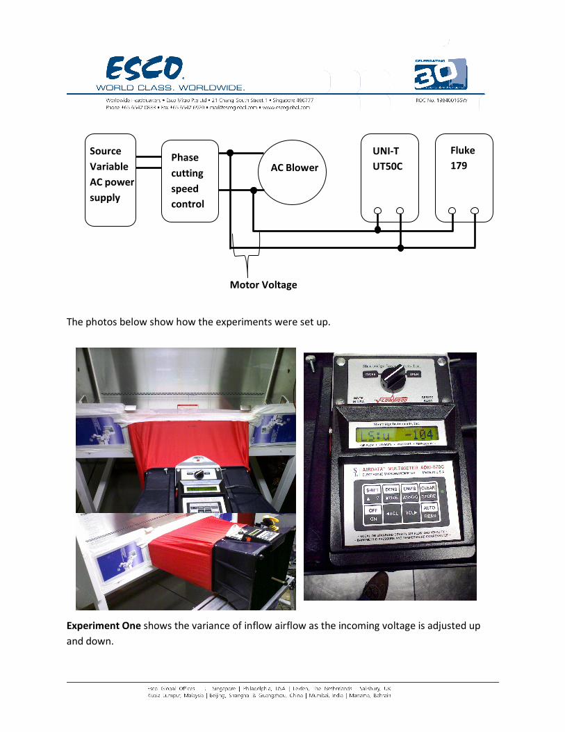
The photos below show how the experiments were set up.
Experiment One shows the variance of inflow airflow as the incoming voltage is adjusted up
and down.
UNI-T
UT50C
Fluke
179 Phase
cutting
speed
control
AC Blower
Source
Variable
AC power
supply
Motor Voltage
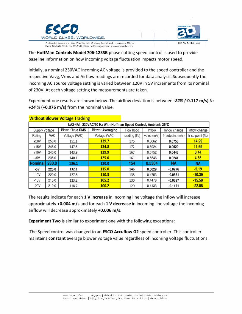
The HoffMan Controls Model 706-123SB phase cutting speed control is used to provide
baseline information on how incoming voltage fluctuation impacts motor speed.
Initially, a nominal 230VAC incoming AC voltage is provided to the speed controller and the
respective Vavg, Vrms and Airflow readings are recorded for data analysis. Subsequently the
incoming AC source voltage setting is varied between ±20V in 5V increments from its nominal
of 230V. At each voltage setting the measurements are taken.
Experiment one results are shown below. The airflow deviation is between -22% (-0.117 m/s) to
+14 % (+0.076 m/s) from the nominal value.
Without Blower Voltage Tracking
Blower True RMS Blower Averaging Flow hood Inflow Inflow change Inflow change
Rating VAC Voltage (VAC) Voltage (VAC) reading (l/s) veloc (m/s) fr setpoint (m/s) fr setpoint (%)
+20V 250.0 151.1 139.7 176 0.6062 0.0758 14.29
+15V 245.0 147.5 134.8 172 0.5924 0.0620 11.69
+10V 240.0 143.9 129.9 167 0.5752 0.0448 8.44
+5V 235.0 140.1 125.0 161 0.5546 0.0241 4.55
Nominal 230.0 136.1 120.0 154 0.5304 NA NA
-5V 225.0 132.1 115.0 146 0.5029 -0.0276 -5.19
-10V 220.0 127.8 110.3 138 0.4753 -0.0551 -10.39
-15V 215.0 123.2 105.2 130 0.4478 -0.0827 -15.58
-20V 210.0 118.7 100.2 120 0.4133 -0.1171 -22.08
LA2-4A1, 230VAC/50 Hz With Hoffman Speed Control, Ambient: 25°C
Supply Voltage
The results indicate for each 1 V increase in incoming line voltage the inflow will increase
approximately +0.004 m/s and for each 1 V decrease in incoming line voltage the incoming
airflow will decrease approximately +0.006 m/s.
Experiment Two is similar to experiment one with the following exceptions:
The Speed control was changed to an ESCO Accuflow G2 speed controller. This controller
maintains constant average blower voltage value regardless of incoming voltage fluctuations.
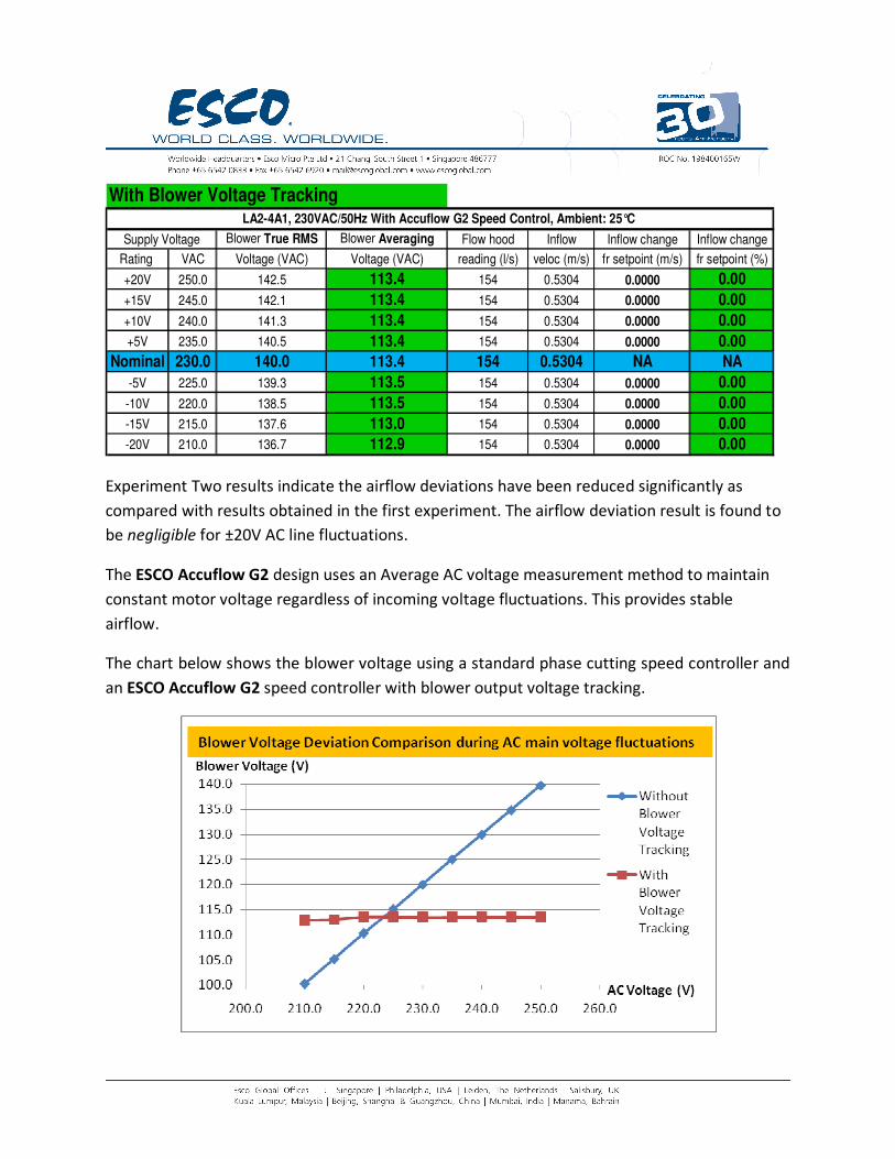
With Blower Voltage Tracking
Blower True RMS Blower Averaging Flow hood Inflow Inflow change Inflow change
Rating VAC Voltage (VAC) Voltage (VAC) reading (l/s) veloc (m/s) fr setpoint (m/s) fr setpoint (%)
+20V 250.0 142.5 113.4 154 0.5304 0.0000 0.00
+15V 245.0 142.1 113.4 154 0.5304 0.0000 0.00
+10V 240.0 141.3 113.4 154 0.5304 0.0000 0.00
+5V 235.0 140.5 113.4 154 0.5304 0.0000 0.00
Nominal 230.0 140.0 113.4 154 0.5304 NA NA
-5V 225.0 139.3 113.5 154 0.5304 0.0000 0.00
-10V 220.0 138.5 113.5 154 0.5304 0.0000 0.00
-15V 215.0 137.6 113.0 154 0.5304 0.0000 0.00
-20V 210.0 136.7 112.9 154 0.5304 0.0000 0.00
LA2-4A1, 230VAC/50Hz With Accuflow G2 Speed Control, Ambient: 25°C
Supply Voltage
Experiment Two results indicate the airflow deviations have been reduced significantly as
compared with results obtained in the first experiment. The airflow deviation result is found to
be negligible for ±20V AC line fluctuations.
The ESCO Accuflow G2 design uses an Average AC voltage measurement method to maintain
constant motor voltage regardless of incoming voltage fluctuations. This provides stable
airflow.
The chart below shows the blower voltage using a standard phase cutting speed controller and
an ESCO Accuflow G2 speed controller with blower output voltage tracking.
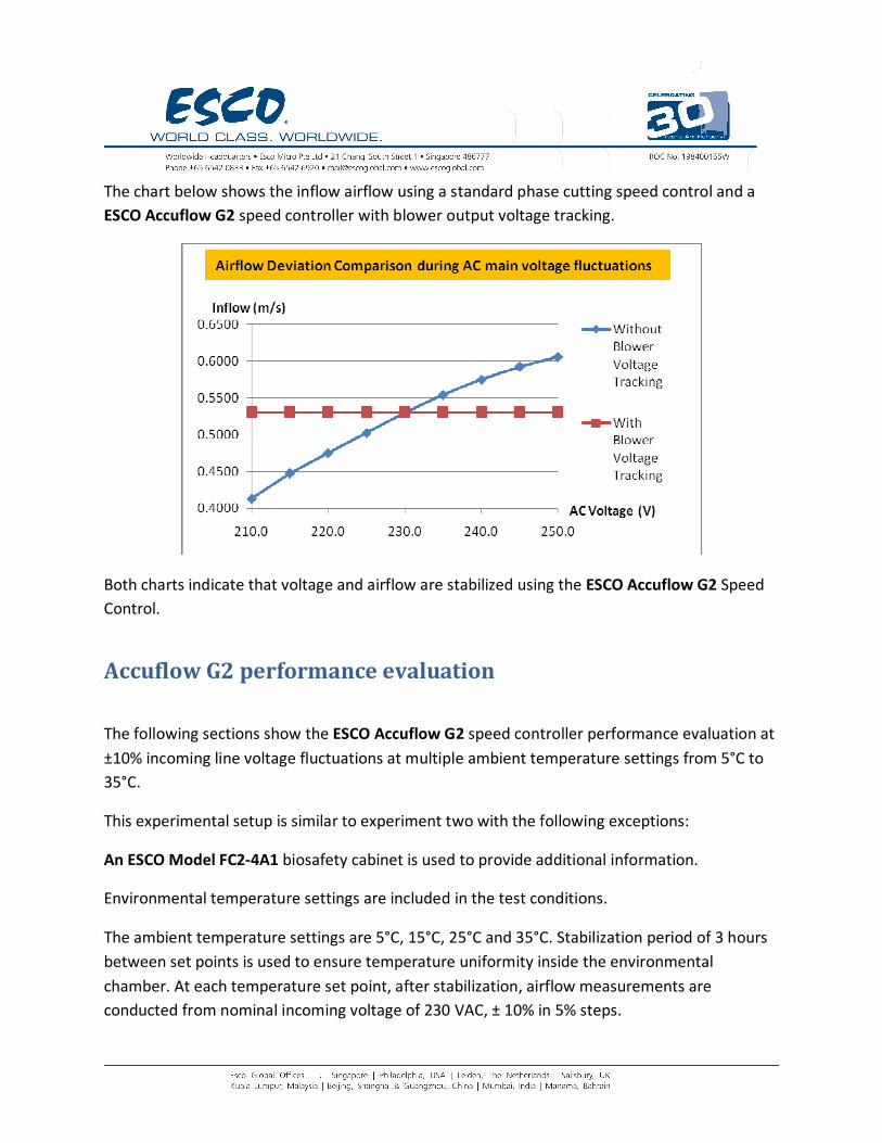
The chart below shows the inflow airflow using a standard phase cutting speed control and a
ESCO Accuflow G2 speed controller with blower output voltage tracking.
Both charts indicate that voltage and airflow are stabilized using the ESCO Accuflow G2 Speed
Control.
Accuflow G2 performance evaluation
The following sections show the ESCO Accuflow G2 speed controller performance evaluation at
±10% incoming line voltage fluctuations at multiple ambient temperature settings from 5°C to
35°C.
This experimental setup is similar to experiment two with the following exceptions:
An ESCO Model FC2-4A1 biosafety cabinet is used to provide additional information.
Environmental temperature settings are included in the test conditions.
The ambient temperature settings are 5°C, 15°C, 25°C and 35°C. Stabilization period of 3 hours
between set points is used to ensure temperature uniformity inside the environmental
chamber. At each temperature set point, after stabilization, airflow measurements are
conducted from nominal incoming voltage of 230 VAC, ± 10% in 5% steps.
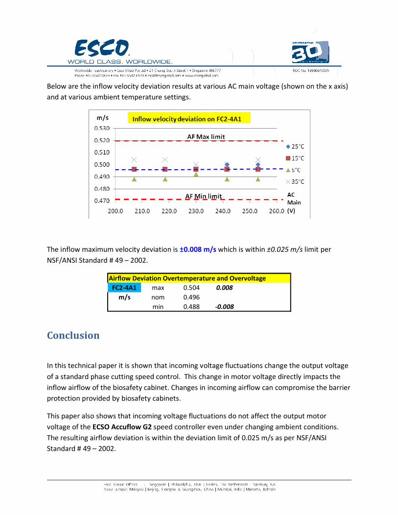
Below are the inflow velocity deviation results at various AC main voltage (shown on the x axis)
and at various ambient temperature settings.
The inflow maximum velocity deviation is ±0.008 m/s which is within ±0.025 m/s limit per
NSF/ANSI Standard # 49 – 2002.
Airflow Deviation Overtemperature and Overvoltage
FC2-4A1 max 0.504 0.008
m/s nom 0.496
min 0.488 -0.008
Conclusion
In this technical paper it is shown that incoming voltage fluctuations change the output voltage
of a standard phase cutting speed control. This change in motor voltage directly impacts the
inflow airflow of the biosafety cabinet. Changes in incoming airflow can compromise the barrier
protection provided by biosafety cabinets.
This paper also shows that incoming voltage fluctuations do not affect the output motor
voltage of the ECSO Accuflow G2 speed controller even under changing ambient conditions.
The resulting airflow deviation is within the deviation limit of 0.025 m/s as per NSF/ANSI
Standard # 49 – 2002.
References
1. True RMS vs AC Average Rectified Multimeter Readings when a Phase Cutting Speed
Control is used, ESCO Technical Paper, 2009.
2. True RMS Definition, application note 106, Linear Technology
3. Airflow Deviation limit on Biosafety cabinets, NSF/ANSI Standard # 49 – 2002.