Embed Size (px)
Citation preview
1
EXCHANGING EXPERTISE SINCE 1893
NWEMS
Understanding Ke Values
Terry Gaiser – Sensus USA
EXCHANGING EXPERTISE SINCE 1893
NWEMS
» Overview
– Pulse Metering Terms and Definitions
– Pulse Calculations
– Pulse Initiators and Configurations
– Pulse Applications
– Pulse Isolation Relays
2
EXCHANGING EXPERTISE SINCE 1893
NWEMS
» Terms & Definitions
–Pulse Metering
–Pulse–Pulse Initiator–Pulse Constant–Ke, PKe, Kh, Kp, Kd, Mp
–CT Ratio, PT Ratio, Multiplier (TF)
– Switch and Relay Forms
EXCHANGING EXPERTISE SINCE 1893
NWEMS
» What is Pulse Metering?
– Pulse Metering is the act of measuring energy usage with a watt‐hour meter, then converting the measured quantity into electronic increments of a constant known value, known as “pulses”
– “Filling & dumping a bucket” analogy
– Common standard of exchanging energy use information between systems
– Simple and Non‐proprietary
3
EXCHANGING EXPERTISE SINCE 1893
NWEMS
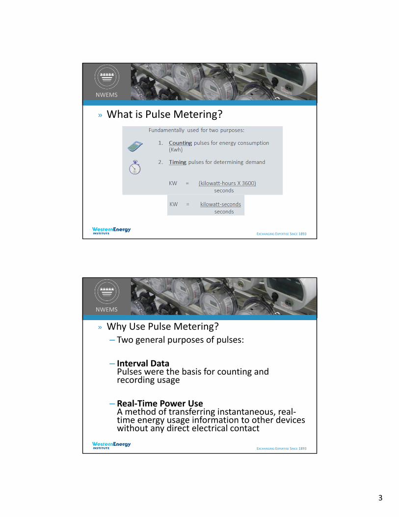
» What is Pulse Metering?
EXCHANGING EXPERTISE SINCE 1893
NWEMS
» Why Use Pulse Metering?– Two general purposes of pulses:
– Interval DataPulses were the basis for counting and recording usage
– Real‐Time Power UseA method of transferring instantaneous, real‐time energy usage information to other devices without any direct electrical contact

4
EXCHANGING EXPERTISE SINCE 1893
NWEMS
» Why Use Pulse Metering?
– Interval Data uses:
– Customer Billing
• Energy charges• Demand charges
• Power Factor charges• Load Factor – Average Demand/ Peak Demand
– TOU Rate Studies
• Survey of energy during specific periods to determine the effect of TOU rate structures.
• Comparing electric heat to gas usage on apartments
EXCHANGING EXPERTISE SINCE 1893
NWEMS
» Why Use Pulse Metering?– System Planning
• Future load growth projections• Transformer sizing• Assisting with rate structures• Load projections – Future consideration for substation, transmission construction
– Customer satisfaction and retention• Offering more Services, Real Time Pricing• Answering billing questions• Reduce their energy costs

5
EXCHANGING EXPERTISE SINCE 1893
NWEMS
» Why Use Pulse Metering?– Utility Applications
• Delivering pulses to multiple systems (Wholesale Delivery points) for system control
• Load Profile Information collection using pulses with external pulse recorder
• Totalization, Billing & Support of special rate structures
• “Check meter” comparison with counting/totalizing register relay
• AMR – Automated Meter Reading meter interface
EXCHANGING EXPERTISE SINCE 1893
NWEMS
» Why Use Pulse Metering?
–Customer Applications
• Energy Management / Demand Control
• Energy Pulses• End‐of‐Interval Pulse• TOU Pulse• Power Factor Calculation

6
EXCHANGING EXPERTISE SINCE 1893
NWEMS
» Why Use Pulse Metering?
» Customer Applications
» Submetering
» To combine meter data with other quantities like inputs from gas, water, temperature, pressure, flow, etc. for Energy Tracking.
» Pulses can be thought of as the lowest common denominator of instantaneous energy information. Reading pulses is generally universal in the EMS industry. Non‐proprietary.
EXCHANGING EXPERTISE SINCE 1893
NWEMS
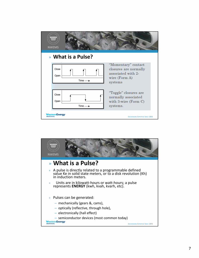
» What is a Pulse?– In Pulse Metering:– Form C (3‐wire) Pulse – A pulse is defined as the change of state or a transition of the pulse initiator – from one state to the opposite state. “Toggle”
– Form A (2‐wire) Pulse – A pulse is a complete cycle of a on‐state transition, a dwell time, and then transition returning to the off‐state. “Momentary”
7
EXCHANGING EXPERTISE SINCE 1893
NWEMS
» What is a Pulse?
EXCHANGING EXPERTISE SINCE 1893
NWEMS
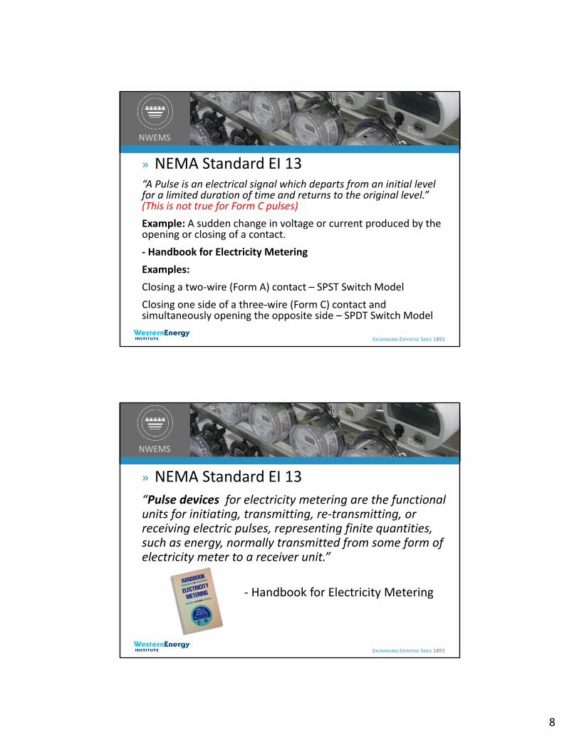
»What is a Pulse?» A pulse is directly related to a programmable defined
value Ke in solid state meters, or to a disk revolution (Kh) in induction meters.
» Units are in kilowatt‐hours or watt‐hours; a pulse represents ENERGY (kwh, kvah, kvarh, etc).
» Pulses can be generated:
– mechanically (gears &, cams),
– optically (reflective, through hole),
– electronically (hall effect)
– semiconductor devices (most common today)
8
EXCHANGING EXPERTISE SINCE 1893
NWEMS
» NEMA Standard EI 13“A Pulse is an electrical signal which departs from an initial level for a limited duration of time and returns to the original level.” (This is not true for Form C pulses)
Example: A sudden change in voltage or current produced by the opening or closing of a contact.
‐ Handbook for Electricity Metering
Examples:
Closing a two‐wire (Form A) contact – SPST Switch Model
Closing one side of a three‐wire (Form C) contact and simultaneously opening the opposite side – SPDT Switch Model
EXCHANGING EXPERTISE SINCE 1893
NWEMS
» NEMA Standard EI 13
“Pulse devices for electricity metering are the functional units for initiating, transmitting, re‐transmitting, or receiving electric pulses, representing finite quantities, such as energy, normally transmitted from some form of electricity meter to a receiver unit.”
‐ Handbook for Electricity Metering

9
EXCHANGING EXPERTISE SINCE 1893
NWEMS
» NEMA Standard EI 13
» “A pulse initiator is any device, mechanical or electrical, used with a meter to initiate pulses, the number of which is proportional to the quantity being measured.”
» “It may include an external amplifier, an auxiliary relay, or both to change the amplitude or waveform of a pulse for re‐transmission to another pulse device.”
EXCHANGING EXPERTISE SINCE 1893
NWEMS
» What is a Ke Value?“Ke” is a representation of the amount of energy (at the pulse generator) in an electronic meter.
Generally expressed in kilowatt‐hours per pulse.
Ke value is programmable
Example: Ke = .001 kWh / pulse or 1 Wh / pulse
Also called the “ Secondary Pulse Constant” or “Energy Constant”
Ke assumes 120VAC/5A at the meter
Ke does not include the CT*PT multiplier of the customer’s metering application.
10
EXCHANGING EXPERTISE SINCE 1893
NWEMS
» What is Pke?
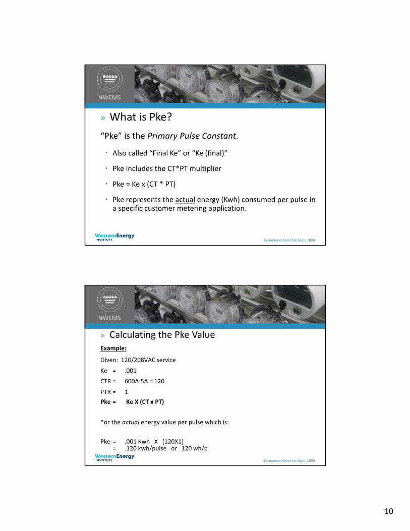
“Pke” is the Primary Pulse Constant.
Also called “Final Ke” or “Ke (final)”
Pke includes the CT*PT multiplier
Pke = Ke x (CT * PT)
Pke represents the actual energy (Kwh) consumed per pulse in a specific customer metering application.
EXCHANGING EXPERTISE SINCE 1893
NWEMS
» Calculating the Pke ValueExample:
Given: 120/208VAC service
Ke = .001
CTR = 600A:5A = 120
PTR = 1
Pke = Ke X (CT x PT)
*or the actual energy value per pulse which is:
Pke = .001 Kwh X (120X1) = .120 kwh/pulse or 120 wh/p

11
EXCHANGING EXPERTISE SINCE 1893
NWEMS
» What is the PKe Value?
Some Meter Manufacturers do this differently:
Given: 120/208VAC service
Kh = 1.8 Wh/rev
P/R(virtual)= Programmable (default = 24)
CTR = 600A:5A = 120
PTR = 1 Pke = Kh X (CT*PT)
P/R
*or the actual energy value per pulse which is:
Pke = 1.8/24 X 120= 9.0 wh/pulse or .009 kwh/p
EXCHANGING EXPERTISE SINCE 1893
NWEMS
» How to set the Pke Value?Working Backwards
Suppose:
Customer requires 32 wh/p
120/208VAC so PTR = 1
CTR = 800A:5A = 160
Ke = Pke / (CT*PT)
Ke = . 032 / 160
Ke = .0002 kWh
12
EXCHANGING EXPERTISE SINCE 1893
NWEMS
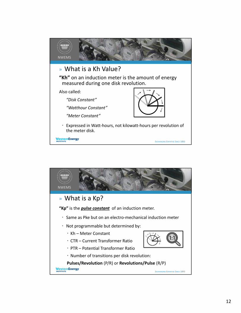
» What is a Kh Value?“Kh” on an induction meter is the amount of energy measured during one disk revolution.
Also called:
“Disk Constant”
“Watthour Constant”
“Meter Constant”
Expressed in Watt‐hours, not kilowatt‐hours per revolution of the meter disk.
EXCHANGING EXPERTISE SINCE 1893
NWEMS
» What is a Kp?
“Kp” is the pulse constant of an induction meter.
Same as Pke but on an electro‐mechanical induction meter
Not programmable but determined by:
Kh – Meter Constant
CTR – Current Transformer Ratio
PTR – Potential Transformer Ratio
Number of transitions per disk revolution:
Pulses/Revolution (P/R) or Revolutions/Pulse (R/P)

13
EXCHANGING EXPERTISE SINCE 1893
NWEMS
» What is the Kp Pulse Constant?
Also called “PW” or “PC”
For calculating the Pulse Constant (Kp):
For Pulses/Revolution:
Kp = Kh X (CT x PT)
P/R
For Revolutions/Pulse:
Kp = Kh X (CT x PT) X R/P
EXCHANGING EXPERTISE SINCE 1893
NWEMS
» What is the Kp Pulse Constant?
Example:
Kh = 1.8 wh/rev
CTR = 600/5=120
PTR = 1
P/R = 4
Kp = 1.8 (120 X 1) 4
= .054 kWh/pulse or 54 Wh/p

14
EXCHANGING EXPERTISE SINCE 1893
NWEMS
» Maximizing ResolutionGreatest resolution = demand divided by the maximum number of pulses in an interval.
Example:
Assume 1,000 kW load, 16,383 pulses/interval max, 15 minute demand interval
Max kWh/interval = 1000 kW/4 = 250 kwh
(kWh/interval)/(# pulses/interval) = 250 kWh/16,383
kWh/pulse (Pke) = .0153 kWh/pulse
So in this example: Pke = 16Wh/pulse
EXCHANGING EXPERTISE SINCE 1893
NWEMS
» Accounting For Growth
Need to add a “fudge factor” so the max number of pulses per interval is not exceeded by load growth. (25% headroom)
Peak KW = 1000KW/.75 = 1333KW
Min Kd = 1333KW/16383 = .0813KW/pulse
Min Kd = .082KW or 82 watts/pulse
Min Pke= .082 / 4 = .0205 Kwh/pulse (~21wh/pulse)
To keep from over‐ranging interval register, Ke must be greater than the Min Pke/TR or in this case:
Ke = > .0205 / 160 = .000128125 kWh
15
EXCHANGING EXPERTISE SINCE 1893
NWEMS
» Accounting For Growth
The greater the Ke value, the fewer pulses per interval and the higher the demand can be measured in the interval, but resolution is lower.
Insure that the maximum # pulses per interval will not overflow (“saturate”) the interval register.
Important: Always round up ‐ not down
EXCHANGING EXPERTISE SINCE 1893
NWEMS
» Pulse Rate vs Pulse Capacity
Pulse Rate = the maximum number of pulses per second at which the pulse sending device is nominally rated.
Pulse Capacity = the maximum number of pulses that the pulse receiving device can accept in a given period of time (usually a second, an hour or a demand interval).

16
EXCHANGING EXPERTISE SINCE 1893
NWEMS
» Typical Max Pulse Capacity & Rates
For old printing demand recorders: Capacity = 999 pulses/interval Max pulse rate = 1.11 pulses/second
For old magnetic tape recorders: Capacity = 7200 pulses/hour Max pulse rate around 2 pulses/second
For older solid state meters: Capacity = 16,383 pulses/interval (14 bit#) Max Pulse rate around 15 ~ 20 pulses/second
Today’s solid state meters Capacity = 65,535 pulses/interval (16 bit#) Max Pulse rate around 40 pulses/second
EXCHANGING EXPERTISE SINCE 1893
NWEMS
» Special Notes
• Pulse constants are usually expressed in 3‐wire (Form C) format.
• Pulse values in 2‐wire format are double the pulse value in 3‐wire formats.
• Meter testing with Form C pulse outputs:
Connect to either the KY or KZ terminals and then input to the test board.
This configuration will only provide ½ the number of pulses for the programmed Ke pulse constant.
Ke value must be doubled for a 2‐Wire Pulse System
17
EXCHANGING EXPERTISE SINCE 1893
NWEMS
» Pulse Initiators
Simply stated…a pulse initiator is a switch
A device attached to an induction or solid state meter that transmits contact closures as the meter measures energy. Often called a KYZ Switch or KYZ Option Board.
Each contact closure or opening (change of state) equals a defined value of energy, generally in kilowatt‐hours/pulse.
Typically used to transmit energy consumption information on a near‐ instantaneous basis to other pieces of equipment which use pulses.
EXCHANGING EXPERTISE SINCE 1893
NWEMS
» Pulse Initiators (aka KYZ Switch) Mechanical pulse initiators used with induction meters Single output have a fixed pulse value determined by a watt‐hour constant (Kh)
and gear ratio between the disk and the device.
Today’s solid state meters allow Multi‐channel, multi‐function output boards both the function and operational value of output relays to be
programmable.
Example:
Let relay #1 represent kWh and each pulse = 192 Wh
Let relay #2 represent TOU time interval signal

18
EXCHANGING EXPERTISE SINCE 1893
NWEMS
» Pulse Types• KYZ – Energy Pulses (Form C or Form A)
• EOI – End Of Interval (Form A)
• TOU – Time‐Of‐Use Signaling (Form A)
• Alert – Peak demand alert
EXCHANGING EXPERTISE SINCE 1893
NWEMS
» Pulse Initiators (Form C simple switch model)

19
EXCHANGING EXPERTISE SINCE 1893
NWEMS
» Pulse Initiators (Form C simple switch model)
EXCHANGING EXPERTISE SINCE 1893
NWEMS
» Pulse Initiator Board
20
EXCHANGING EXPERTISE SINCE 1893
NWEMS
» Contact Types“Dry” Contacts have no electricity applied to them from the device in which they are installed.
External voltage is supplied.
Electrically Isolated
“Sourced” Voltage Contacts generally have line voltage sourced to Y and Z terminals.
Less Frequently Used
Used only in special applications where non‐standard interface is required.
Not isolated
EXCHANGING EXPERTISE SINCE 1893
NWEMS
»How Do Dry Contacts Work?Wetting Voltage – “sense” voltage is applied from an external source on the “K” terminal. It can be detected on the “Y” and “Z” terminals alternately as the contacts open close.
Utility Industry convention generally dictates that the receiving device supplies the wetting voltage to the sending device (relay to meter, energy control system to relay).
This is not necessarily true with the Process Control Industry or Energy Management Industry.

21
EXCHANGING EXPERTISE SINCE 1893
NWEMS
» Contact Forms
• Form “A” – Normally‐open 2‐wire contact; SPST
• Form “C” – A set of contacts consisting of one form A and one form B with a single common contact (“K”); SPDT. One contact “breaks” before the other “makes”.
• Each change of state is a pulse
• Recommended for applications where no overlapping of contacts can be tolerated
• “Break Before Make”
EXCHANGING EXPERTISE SINCE 1893
NWEMS
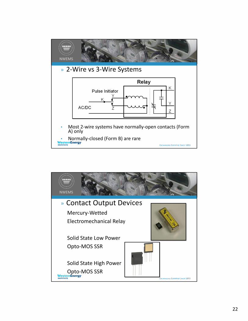
» 2‐Wire vs 3‐Wire Systems
» 3‐wire systems have Form C contacts
22
EXCHANGING EXPERTISE SINCE 1893
NWEMS
» 2‐Wire vs 3‐Wire Systems
• Most 2‐wire systems have normally‐open contacts (Form A) only
• Normally‐closed (Form B) are rare
EXCHANGING EXPERTISE SINCE 1893
NWEMS
» Contact Output DevicesMercury‐Wetted
Electromechanical Relay
Solid State Low Power
Opto‐MOS SSR
Solid State High Power
Opto‐MOS SSR

23
EXCHANGING EXPERTISE SINCE 1893
NWEMS
» Relay Terminology
• Latching Relay – A relay that will stay in the last position it is in when voltage is removed; also called a “Bi‐Stable” Relay ‐ two stable states
• Non‐Latching Relay – A relay with one stable state; also called “Monostable”
• The Normally‐Closed contact returns to the closed state in absence of power. (Current can flow)
• The Normally‐Open contact returns to the open state. (No current flow)
EXCHANGING EXPERTISE SINCE 1893
NWEMS
» Relay Terminology
• Polarized Relay
• Uses +Vdc and –Vdc alternately to simulate 3‐Wire system using only two wires.
• Generally requires a specific‐purpose transmitting and receiving relays for use in sending pulses over relatively long distances.
• Used a polarity reversing scheme to latch and unlatch a latching relay

24
EXCHANGING EXPERTISE SINCE 1893
NWEMS
» Info Needed for Pulse Metering Applications
Type of meter, including Ke or Kh, voltage & current ratings
CT & PT ratings and ratios
Typical and Maximum kW demand
Interval length – usually 15 minutes
Required contact types ‐ A or C
Desired Pulse Rate or Resolution
Programming limitations: Maximum number of pulses per interval
Pulse capacity or the maximum pulse acceptance rate of the receiving equipment: Maximum number of pulses per second
EXCHANGING EXPERTISE SINCE 1893
NWEMS
» Isolation Relays
Isolation relays are pulse repeating relays that provide an additional level of electrical protection between the device that originates a contact closure (such as utility‐owned meters with KYZ pulse output) and the receiving device (such as a customer‐owned energy management or monitoring equipment).
They can additionally act as a “pulse splitter” or “pulse duplicator” to send one KYZ pulse output from the pulse initiator in the meter to multiple isolated & independent devices, such as RTU’s, SCADA systems, recorders, EMS etc.

25
EXCHANGING EXPERTISE SINCE 1893
NWEMS
» Isolation Relay Types
Isolation Relays are divided into two basic types:
Line Wetting Voltage – These were the original isolation relays that used line voltage across the KYZ metering output to drive the input of the isolation relay. Not recommended.
Low Voltage Wetting Voltage – These have a small transformer‐isolated DC power supply included in the relay to generate a +12 to +24VDC wetting voltage and is current limited for internal short circuit protection. Using a transformer isolated power supply adds a second dielectric or isolation barrier to the application.
EXCHANGING EXPERTISE SINCE 1893
NWEMS
» Why do we use these Devices?• Protection: prevent possible damage to meter
• To keep the customer’s voltage and current out of the meter
• Protect meter from Lightning; Protect customer equipment
• Adds a second dielectric barrier between the utility meter and the customer’s equipment.
• Adds Fusing to the customer output circuit
• Separate Line and ground potentials
• Mitigate Ground rise problems between systems
• Pulse Voltage conversion
• Scale pulse value from one value to required value ‐ to reduce # of pulses

26
EXCHANGING EXPERTISE SINCE 1893
NWEMS
» Pulse Isolation Relay Application
EXCHANGING EXPERTISE SINCE 1893
NWEMS
» Pulse Isolation Relay Application
27
EXCHANGING EXPERTISE SINCE 1893
NWEMS
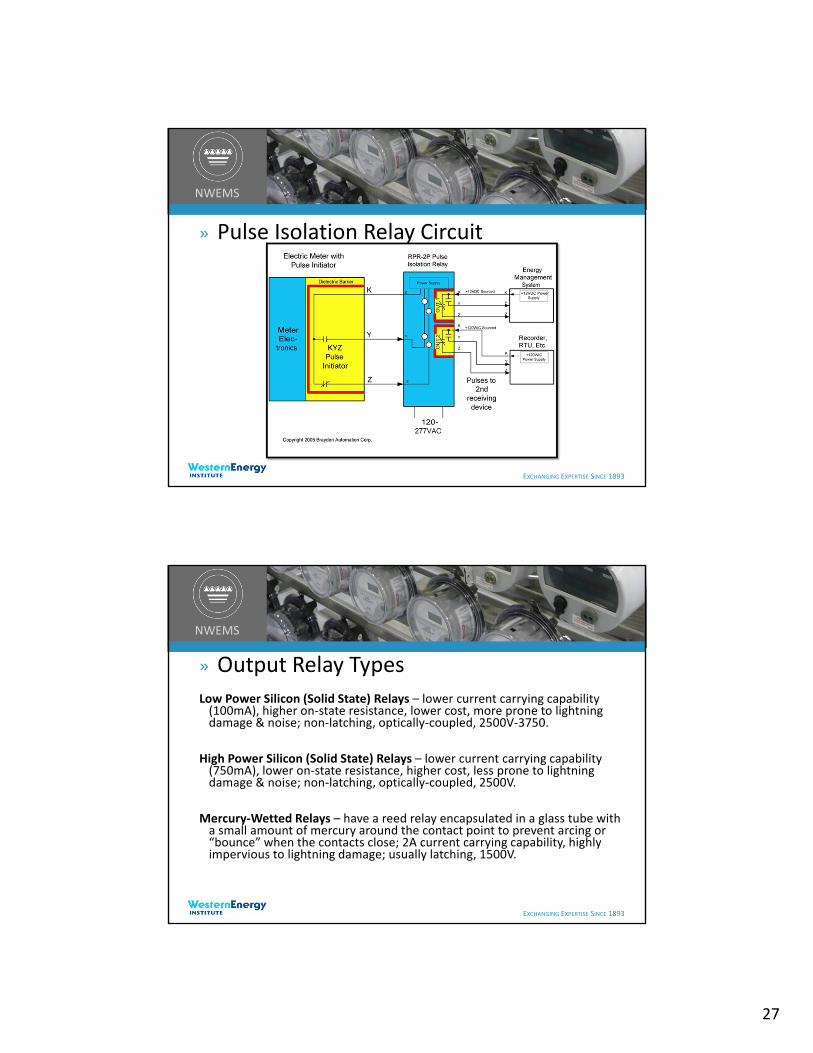
» Pulse Isolation Relay Circuit
EXCHANGING EXPERTISE SINCE 1893
NWEMS
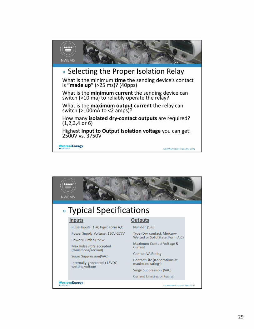
» Output Relay Types
Low Power Silicon (Solid State) Relays – lower current carrying capability (100mA), higher on‐state resistance, lower cost, more prone to lightning damage & noise; non‐latching, optically‐coupled, 2500V‐3750.
High Power Silicon (Solid State) Relays – lower current carrying capability (750mA), lower on‐state resistance, higher cost, less prone to lightning damage & noise; non‐latching, optically‐coupled, 2500V.
Mercury‐Wetted Relays – have a reed relay encapsulated in a glass tube with a small amount of mercury around the contact point to prevent arcing or “bounce” when the contacts close; 2A current carrying capability, highly impervious to lightning damage; usually latching, 1500V.

28
EXCHANGING EXPERTISE SINCE 1893
NWEMS
» Special NotesMW isolation relays must be installed in a vertical position(within 30 degrees of vertical).
Some isolation relays may have fusesfor each output relay AND a slow blow input fuse (~.25 ‐ .5 amp).
Some relays offer redundant fusing so customer cannot defeat fuse with a large amperage fuse.
EXCHANGING EXPERTISE SINCE 1893
NWEMS
» Selecting the Proper Isolation Relay• Self‐contained (outdoor) or modular (indoor)?
• Input format (2‐wire, 3‐wire or field‐selectable)?
• Output format (2‐wire, 3‐wire, dividing type, or field‐selectable)?
• Sense Voltage (Line voltage or isolated low voltage wetting voltage)?
• Can the sending device accept non‐isolated line voltages?
29
EXCHANGING EXPERTISE SINCE 1893
NWEMS
» Selecting the Proper Isolation RelayWhat is the minimum time the sending device’s contact is “made up” (>25 ms)? (40pps)
What is the minimum current the sending device can switch (>10 ma) to reliably operate the relay?
What is the maximum output current the relay can switch (>100mA to <2 amps)?
How many isolated dry‐contact outputs are required? (1,2,3,4 or 6)
Highest Input to Output Isolation voltage you can get: 2500V vs. 3750V
EXCHANGING EXPERTISE SINCE 1893
NWEMS
» Typical Specifications
30
EXCHANGING EXPERTISE SINCE 1893
NWEMS
» Typical SpecificationsContact On‐State Resistance 50 milliohms max for MW 20 ohms typical for LP SSR 1.7 ohms typical for HP SSR
Insulation Resistance (50 megohms typical)
Operate and Release Time (Typically 1 to 10 milliseconds)
Maximum Dielectric Voltage 1500V for MW 2500 ‐ 3750V for SSR
EXCHANGING EXPERTISE SINCE 1893
NWEMS
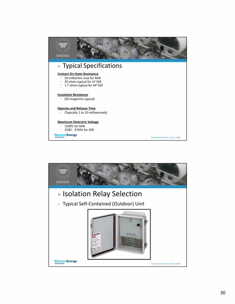
» Isolation Relay Selection» Typical Self‐Contained (Outdoor) Unit
31
EXCHANGING EXPERTISE SINCE 1893
NWEMS
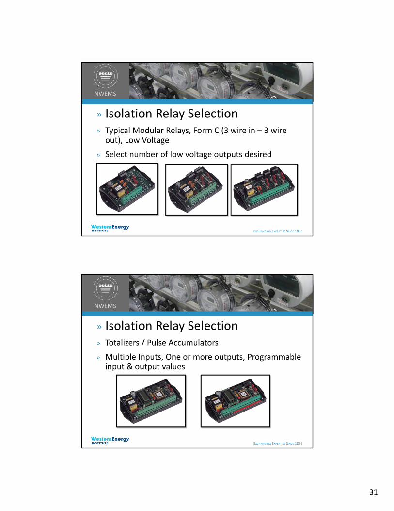
» Isolation Relay Selection» Typical Modular Relays, Form C (3 wire in – 3 wire out), Low Voltage
» Select number of low voltage outputs desired
EXCHANGING EXPERTISE SINCE 1893
NWEMS
» Isolation Relay Selection» Totalizers / Pulse Accumulators
» Multiple Inputs, One or more outputs, Programmable input & output values
32
EXCHANGING EXPERTISE SINCE 1893
NWEMS
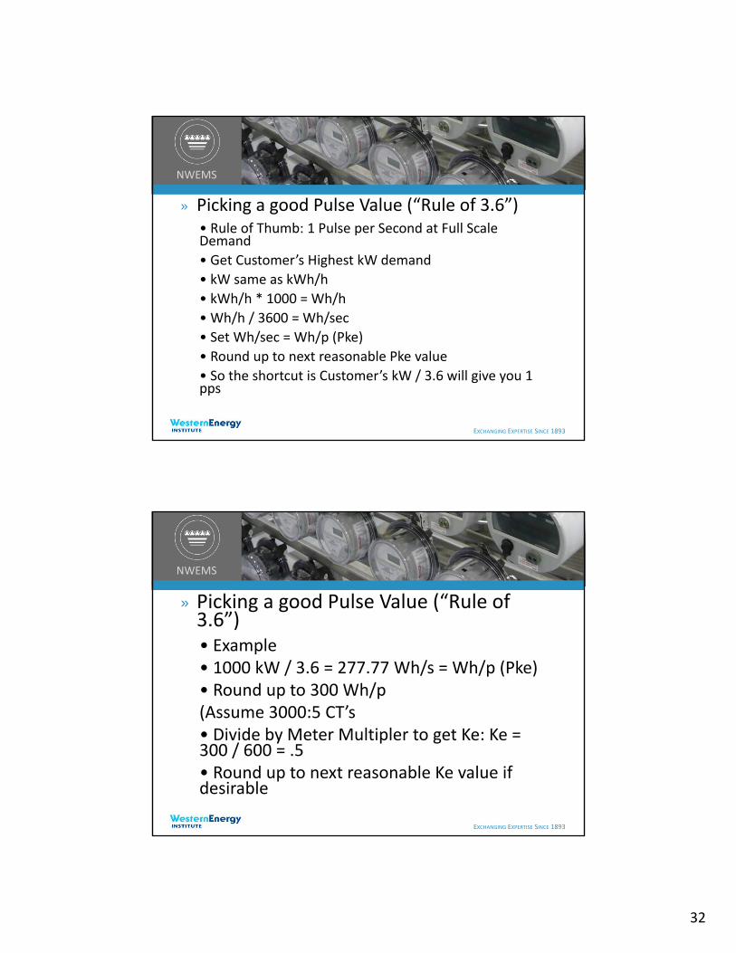
» Picking a good Pulse Value (“Rule of 3.6”)• Rule of Thumb: 1 Pulse per Second at Full Scale Demand
• Get Customer’s Highest kW demand
• kW same as kWh/h
• kWh/h * 1000 = Wh/h
• Wh/h / 3600 = Wh/sec
• Set Wh/sec = Wh/p (Pke)
• Round up to next reasonable Pke value
• So the shortcut is Customer’s kW / 3.6 will give you 1 pps
EXCHANGING EXPERTISE SINCE 1893
NWEMS
» Picking a good Pulse Value (“Rule of 3.6”)• Example• 1000 kW / 3.6 = 277.77 Wh/s = Wh/p (Pke)• Round up to 300 Wh/p(Assume 3000:5 CT’s• Divide by Meter Multipler to get Ke: Ke = 300 / 600 = .5• Round up to next reasonable Ke value if desirable

33
EXCHANGING EXPERTISE SINCE 1893
NWEMS
» Review• A pulse is a switch closure – SPDT• Each switch closure is a representation of
energy which has been consumed• Dry contacts must be wetted with a voltage
generally from the pulse receiving (“downstream”) device
• 2‐wire pulse values are double 3‐wire values• Isolation Relays can protect your meter and
your customer’s equipment: Think “separation of circuits”.
EXCHANGING EXPERTISE SINCE 1893
NWEMS
Questions?
Thank You!Special thanks to Bill Brayden –President of Brayden Automation
Corp./Solid State Instruments for the content of this presentation