Embed Size (px)
Citation preview

Understanding Projection Systems
- 1 -
Understanding Projection Systems
A Point: A point has no dimensions, a theoretical location that has neither length, width nor height.
A point shows an exact location in space. It is important to understand that a point is not an object, but a
position. We represent a point by placing a dot with a pencil.
A Line: A line is a geometric object that has length and direction but no thickness. A line may be straight or
curved. A line may be infinitely long. If a line has a definite length it is called a line segment or curve segment.
A straight line is the shortest distance between two points which is known as the true length of the line. A line
is named using letters to indicate its endpoints.
AB - Straight Line Segment AB – Curved Line Segment
A line may be seen as the locus of a point as it travels between two points.
A line can graphically represent the intersection of two surfaces, the edge view of a surface, or the limiting
element of a surface.
A Plane: A plane is a flat surface which is infinitely large
with zero thickness.
Just as a point generates a line, a line can generate a plane.
A portion of a plane is referred to as a lamina.
A Plane may be defined in a number of different ways.
B
A A
B
A B
A
B

Understanding Projection Systems
- 2 -
A plane may be defined by;
(i) 3 non-linear points (ii) A line and a point (iii) Two intersecting lines (iv) Two Parallel Lines
(The point can not lie on the line)
Descriptive Geometry: refers to the representation of 3D objects in a 2D format using points, lines and planes.
This format yields accurate information regarding lengths of lines and positions of objects relative to an origin.
A view is created by projecting an object onto a plane. The position of the plane and the viewing direction
relative to the object will determine the resulting view.
In this case, the television is viewed from the front. The plane is placed behind the television perpendicular to
the line of vision. The view is projected onto the plane at 90º. The resulting view is contained on the plane.
This type of projection is known as Orthographic Projection or Orthogonal Projection.
Does one view give us the complete picture?
Pictured below are two bundles of €20 Notes, one contains significantly more than the other. Which would you
choose? (a) or (b)?
(a) (b)
Projector
Plane

Understanding Projection Systems
- 3 -
The views shown do not give enough information to enable us to make a decision as to which contains the most
money. What view would you require to make a confident choice?
The views below show the heights of both bundles. Bundle (b) clearly contains more than bundle (a).
This view indicates a greater quantity of notes but leaves us undecided as to what the notes are. The top views
indicate that both bundles are made up of €20 notes. The front view indicates the amount of notes in each. To
confidently make a decision as to which contains the most money both views are required.
Creating the views: As discussed earlier, in order to create a particular view of an object a plane must be placed
in a position onto which the view will be projected. The views required in this case are a front view and top
view.
A plane is required behind the object onto which the front view will be projected. Because the line of vision is
horizontal, and the plane is positioned perpendicular to the line of vision, this plane will be vertical.
Similarly for the Top View, a plane will be placed underneath the object. As the line of vision is vertical the
plane perpendicular to the line of vision will be horizontal.
The line where the Vertical and Horizontal Planes meet is the line of intersection and is referred to as the
xy line, the Horizontal Plane being the X plane and the Vertical Plane the Y Plane.
(a) (b)
Vertical Plane
Front View
Vertical
Projection Line
xy line
Horizontal
Projection Line

Understanding Projection Systems
- 4 -
In Orthographic Projection, these two principal planes are used and are referred to as the Planes of Reference.
The view shown below displays the model when viewed from the front. It is important to note that, when
viewing the model from the front, the horizontal plane does not disappear but is seen as an edge. This edge view
coincides with the line of intersection between the two planes – xy line.
The concept of a plane appearing as an edge will be explored further later.
When viewed from the top the model appears as shown below. As with the horizontal plane in the front view,
the vertical plane is seen as an edge, coinciding with the xy line.
Horizontal Plane
Top View
Horizontal Projection
Lines to Vertical Plane
Horizontal Plane
xy line Vertical Plane
Vertical Projection Lines
to the Horizontal Plane
Horizontal Plane XY Line
Vertical Plane
The distance of an object above the horizontal plane is equal to
the distance of the front view above the xy line

Understanding Projection Systems
- 5 -
.
The two views may be presented simultaneously and appear as shown below.
The xy line is common to both views. The front view is presented overhead the top view. The projection lines
join the front and top views and are perpendicular to the xy line.
As discussed previously, the xy line represents the edge view of the vertical plane in plan view and the edge
view of the horizontal plane in the front view.
In order to investigate the planes of reference further we will model a representation of them in SolidWorks.
The next steps will take us through how to create the model.
Vertical Plane
Projection Lines
Front View
Top View
xy line
Horizontal Plane
Vertical Plane
in top view.
Horizontal Plane
in front view.
The distance of an object in front of the vertical plane is equal
to the distance of the top view in front of the xy line

Understanding Projection Systems
- 6 -
Getting started
Choosing a Plane Create a sketch.
The principal planes of reference are
displayed, along with the Right Plane.
The Origin may be seen as the point common to
all three planes.
At this stage we will model only the Front
and Top Plane.
Creating the sketch Create a rectangular sketch on the Top Plane.
The Origin is coincident with the midpoint of
the line on the left hand side.
Select Smart Dimension from the sketch
toolbar and dimension the sketch as shown.
Creating the Planar To create a plane to represent the
Surface Horizontal Plane choose Insert, Surface, Planar…
from the drop down menu.
The bounding rectangle will be chosen automatically.
If not, choose one of the extremities of the sketch.

Understanding Projection Systems
- 7 -
Edit Appearance A grey colour is applied to the planar surface
by default.
Edit the appearance to reflect a more
appropriate colour.
Rename Feature Rename the feature Horizontal Plane in the
Feature Manager.
Creating the Create the sketch shown on the front plane,
Vertical Plane using only the dimension shown.
The midpoint of the left hand side is
coincident with the origin.
The sketch is fully defined by adding a
coincident relation between the right hand
side and the horizontal plane, as shown
Planar Surface Create a Planar Surface using this sketch to represent the Vertical Plane.
Edit Feature Rename the feature Vertical Plane.
Edit the colour to reflect that of the
Horizontal Plane.
Representing the Once modeled, you will notice that the xy line is not clearly defined. It is possible to see
xy line the line of intersection between the two planes but it is not possible to pick it.
Intersection Curve In order to determine the line of intersection Intersection Curve will be used.

Understanding Projection Systems
- 8 -
Intersection Curve will open a sketch and create a sketch
line at the intersection of the two planar surfaces
Creating the sketch Choose Tools, Sketch Tools, Intersection Curve…
from the drop down menu.
A new 3D Sketch will appear in the
Feature Manager Design Tree.
Highlight the two planar surfaces.
The 3D Sketch (xy line) will be created
representing the line of intersection
between the Vertical and Horizontal
Planes.
Rename the feature xy line
Edit the appearance, color to black
Adding Annotation Add the Notes shown to represent the various features.
Save the model as Orthographic Projection.
Basic Principles These two principal planes are used in orthographic projection, one horizontal and one
vertical. The two planes divide space into 4 quadrants.
Choose Left View, the xy line appears as a point and the planes appear as edges.
The angle between the planes, 90º, is shown in this view also. This is referred to as the
Dihedral Angle
The quadrants are numbered as shown.
1st Quadrant 2
nd Quadrant
3rd
Quadrant 4th
Quadrant
Left View

Understanding Projection Systems
- 9 -
In descriptive geometry the object is positioned in one of
these quadrants. It is represented by its projections onto
the vertical and horizontal planes, yielding the front
and top views respectively. The front view is called the
elevation, the top view is called the plan
When the object is placed in the 1st quadrant the
resulting projection is known as First Angle Projection.
When placed in the 3rd
quadrant the projection is
referred to as Third Angle Projection
To show these views on a single plane the horizontal
and vertical planes are opened out to coincide
with one another.
It is convention that the 1st quadrant is always opened out
The 2nd
and 4th
Angle Projections are not commonly used as
the rabatment would result in superimposed views.
We will now investigate the different outcomes when an object is positioned
in either the 1st or 3
rd quadrant ie First and Third Angle Projection
For the purpose of this exercise we will use a cylinder.
Creating the cylinder in the 1st quadrant
Sketch details Create the sketch shown on the
Horizontal Plane in the 1st Quadrant.
(A sketch may be created on a planar surface)
Creating the Extrude the sketch to a depth of 60mm
Feature to create the cylinder.
Appearance Edit the face appearance colors of the
cylinder to reflect those shown below.
Rename the feature Cylinder
View Rotation View Rotation allows the speed of transition from
one view to another to be changed.
For the purpose of demonstration it is best to slow
down the speed of rotation.
To edit the View Rotation setting choose:
Tools/Options…

Understanding Projection Systems
- 10 -
Select the View Rotation tab on the LHS
Drag the view animation speed to the
position shown. Choose OK
Orthographic Views Investigate the various orthographic views of the object using
Top, Front, Right, Left and Isometric Views.
The slower transition speed allows us to clearly
see the creation of each view.
Projecting onto the In order to create the orthographic projection onto the planes of reference we will use a
Planes command called Convert Entities
Convert Entities: One or more curves may be created in a sketch by projecting the
geometry of a solid onto a sketch plane
Projecting the Choose Front View.
Front View. Create a sketch on the Vertical Plane
Pre-select the edges shown
Hold down the shift key whilst picking
to make multiple selections.
It may be necessary to move to an isometric
view in order to choose the base.
Choose Isometric View
From the Sketch toolbar choose
Convert Entities
The extremities of the cylinder,
front view, are projected onto the
front plane, resulting in a rectangular
shaped projection.
Exit the sketch.
Extruded Extrude the sketch outwards to a depth of .01mm
Boss/Base
Appearance Edit the Face Appearance Color to reflect
that of the surface of the cylinder.

Understanding Projection Systems
- 11 -
Rename the feature as Elevation.
Projecting the Choose Top View.
Top View. Create a sketch on the Horizontal Plane.
Pre-select the circular extremity of the cylinder.
From the Sketch toolbar choose Convert Entities
Choose Isometric View
Because the cylinder is sitting on the horizontal plane the projected view will coincide
with its base.
To see the projected view we will hide the model.
Hide the cylinder To hide the cylinder right click on ‘Cylinder’ in the feature manager design tree and
select Hide. The cylinder has been hidden but it is not deleted
The circular projection of the cylinder is now exposed on the Horizontal Plane
Extruded Extrude the sketch to a depth of .01mm
Boss/Base De-select Merge Result
Appearance Edit the Face Appearance Color to reflect
that of the top of the cylinder.
Rename the feature as Plan
Rabatment To represent this projection on a planar surface
we must visualise the rabatment of the planes.
Convention tells us that the 1st quadrant is always
opened out, thereby rotating the horizontal plane
to a vertical position, positioning the top view
underneath the front view, on a single plane.
The orthographic projection of the cylinder in
First Angle Projection is shown opposite

Understanding Projection Systems
- 12 -
Representing the cylinder in Third Angle Projection
To represent the cylinder in third angle projection we must first place the cylinder in the 3rd
quadrant. We will
do this by editing both the feature ‘Cylinder’ and the sketch used to create it.
Editing the sketch Choose Top View.
Right Click on Cylinder and select
Edit Sketch.
Delete the dimension 35mm from the
Vertical Plane
Select the circle centre and drag it behind
the vertical plane.
Dimension it 35mm behind the plane as shown.
Exit the sketch. Right Click on ‘Cylinder’
and select Show.
The cylinder is now positioned in the 2nd
Quadrant.
Editing the Feature To place the cylinder in the 3rd
quadrant we will
edit the direction of extrusion of the feature.
Right Click on ‘Cylinder’ and select Edit Feature
Reverse the direction by selecting
Select OK
Transparency Reduce the transparency of both planes to 0.6
Transparency settings are found under;
Face Appearance, Color.., Optical Properties
Third Angle Projection

Understanding Projection Systems
- 13 -
In Third Angle Projection the planes are positioned in front and overhead the
object respectively. For that reason it is assumed that the planes are transparent.
Hide the cylinder Hide the cylinder as before. The projections
of the cylinder remain on the planes.
Rabatment Following convention the planes rabat in such
a way that the first quadrant is opened out.
This results in the top view rotating to a position
above the front view, contained on a single plane.
The orthographic projection of the cylinder in
Third Angle Projection is shown opposite
For the remainder of this document we will pursue the fundamental concepts of projection systems using First
Angle Projection.
Using a similar method to that used in the creation of the
planes of reference model, we will create a new model
based on the first quadrant only.
Note: The origin will be located as shown.
The planar surfaces will measure 100mm X 150mm
The xy line is generated using Intersection Curve.
Add extruded text to both the vertical and horizontal
planes to identify them.
For clarity the appearance colour of both planes
is chosen differently
Origin

Understanding Projection Systems
- 14 -
The xy line
xy line as a true length
As discussed previously, the xy line is the line of intersection between the vertical plane and the horizontal
plane. The line is therefore contained on both planes.
A definition of a straight line states that it is “the shortest distance between two points which is known as the
true length of the line”.
Choose Front View.
When we look at the elevation of the planes of reference
we are looking perpendicular to the front plane.
Because the xy line is contained on the plane it will
appear as a true length in elevation.
Note: The horizontal plane appears as an edge coinciding
with the xy line
Choose Top View.
Similarly in plan, because we are looking at 90º to the
horizontal plane, and the xy line is contained on the
horizontal plane, the resulting view of the xy line
will be a true length.
Note: The vertical plane appears as an edge coinciding
with the xy line
A line will be seen as a true length when it is parallel to the
projection plane it is projected on to.

Understanding Projection Systems
- 15 -
Activity – using the reduced view animation speed flick between the front, top
and isometric views and note the concepts discussed above.
xy line as a point.
Choose Left View.
In choosing left view we are looking parallel to the vertical
and horizontal planes, along the true length of the xy line
and we see it as a point.
When a point view of the xy line is taken you will notice that the vertical and horizontal planes appear as edges.
The xy line projects as a point when we look along its true length. The xy line is contained on both the vertical
and horizontal planes. Therefore the vertical and horizontal planes will appear as edge views when we view the
xy line as a point.
We will now use the first angle projection planes model to investigate the projections of points and lines.
Edge view of the
Vertical Plane
Point View of the xy line
Edge view of the
Horizontal Plane
A plane will appear as an edge when a line contained on it
projects as a point
A line will be seen as a point when a view is taken along its
true length.

Understanding Projection Systems
- 16 -
Co-ordinates of a Point
Choose 3D Sketch. Select Point.
Position the point as shown opposite.
If the point is positioned with the front or top plane in the
background it will automatically be created coincident
with that plane
Deselect point to end the command.
Rename the feature Point
Highlight the point. The XYZ co-ordinates of the point appear in the
Point Property Manager.
These co-ordinates refer to the position of the point relative to the origin. The origin refers to the intersection of
the front, top and right planes.
X Co-ordinate
Choose front view. You will notice that the point is positioned
to the left of the origin, hence the X co-ordinate is minus.
Change this value to 60. The point moves to the right.
Smart dimension from the origin to the point.
You will notice that this value is 60, therefore the X co-ordinate
refers to the distance left or right of the origin, or right plane.
Y Co-ordinate
Highlight the point.
Change the Y co-ordinate to 50. The point moves upwards.
Smart dimension from the xy line to the point.
You will notice that this value is 50, therefore the Y co-ordinate

Understanding Projection Systems
- 17 -
refers to the distance above or below the origin, or the top plane.
Delete these dimensions
Z Co-ordinate
Highlight the point. Choose Top View.
The co-ordinate value for Z is 0 and as we can see it is
coincident with the vertical plane.
Change the Z co-ordinate to 40. The point will move to
a position 40mm in front of the vertical plane and
the origin.
Delete the 40mm dimension.
It is important to be clear that a point shows an exact location in space. It is important to understand that a point
is not an object, but a position, with XYZ co-ordinates relative to a fixed point, known as the origin.
Activity – Experiment with the front and top views, along with various co-ordinate values, to gain an
appreciation for the significance of XYZ values and the points location relative to the origin and the
chosen views.
Delete the feature Point from the Feature Manager Design Tree.
Projections of a line
Choose 3D Sketch. Select Line.
Create a 3D Sketch line as shown opposite.
A straight line is the shortest distance between two points
Just as with a point, to edit the line, select the endpoints
individually and edit the co-ordinates of the point which
appear in the Point Property Manager.

Understanding Projection Systems
- 18 -
Activity – input various XYZ values for both endpoints and note
the positioning of the line relative to the origin. Experiment with
positive and negative values.
Traces of a line
These are the points where the line, extended if necessary, intersects the vertical and horizontal planes.
When a line intersects a plane the trace produced is a point.
The trace on the horizontal plane is called the horizontal trace (HT) and the trace on the vertical plane the
vertical trace (VT)
What co-ordinates would ensure that the lines intersect both the vertical
and horizontal planes?
From our experience of the co-ordinates, the Y co-ordinate refers to the distance above/below the horizontal
plane, and Z co-ordinate the distance in front of or behind the vertical plane. If either of these values are set to 0
then the point will sit on that plane.
Edit the endpoints individually to reflect the co-ordinates shown below.
Choose Right View
We can see that the line intersects both the vertical and horizontal planes.
?
?
?
Vertical Trace (VT)
Horizontal Trace (HT)
Edge view of the
Vertical Plane
Edge view of the
Horizontal Plane
Line
Understanding Projection Systems
- 19 -
Projections of a line
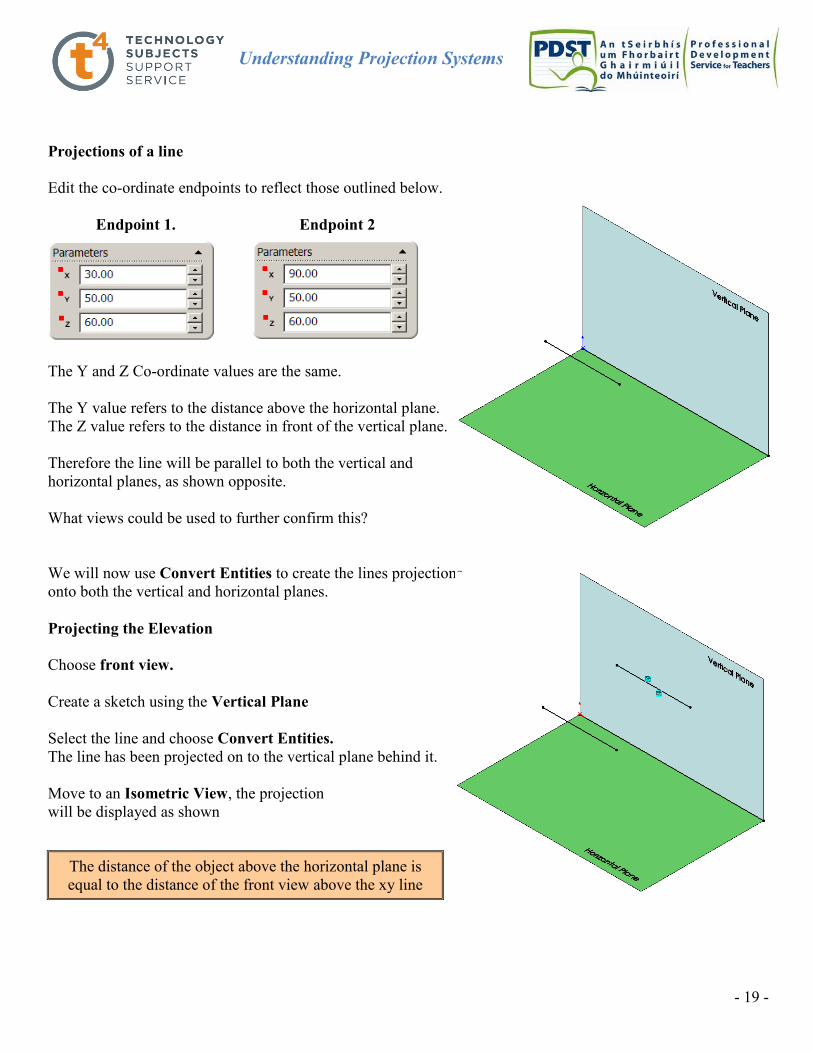
Edit the co-ordinate endpoints to reflect those outlined below.
Endpoint 1. Endpoint 2
The Y and Z Co-ordinate values are the same.
The Y value refers to the distance above the horizontal plane.
The Z value refers to the distance in front of the vertical plane.
Therefore the line will be parallel to both the vertical and
horizontal planes, as shown opposite.
What views could be used to further confirm this?
We will now use Convert Entities to create the lines projections
onto both the vertical and horizontal planes.
Projecting the Elevation
Choose front view.
Create a sketch using the Vertical Plane
Select the line and choose Convert Entities.
The line has been projected on to the vertical plane behind it.
Move to an Isometric View, the projection
will be displayed as shown
The distance of the object above the horizontal plane is
equal to the distance of the front view above the xy line

Understanding Projection Systems
- 20 -
Projecting the Plan
Choose top view.
Create a sketch using the Horizontal Plane
Select the line and choose Convert Entities.
The line has been projected on to the horizontal plane
underneath it.
Move to an Isometric View, the projections
will be displayed as shown
True length of the line
The line was initially created 60mm long using the co-ordinates. This is the true length of the line.
If we smart dimension the projected lines created in both the elevation and plan view sketches we will find that
they too are 60mm long. Therefore the elevation and plan show the line as a true length. Why?
Because the line is parallel to both the front and top plane the line is seen as a true length in both the elevation
and plan.
Point view of the line
In order to get a point view of the line we will first create a plane on which to project onto. The plane is
positioned perpendicular to the line.
As discussed previously, a plane may be defined in 4 ways;
The distance of the object in front of the vertical plane
is equal to the distance of the top view in front of the xy line
A line will be seen as a true length when it is parallel to the
projection plane it is projected on to.
Understanding Projection Systems
- 21 -
(i) 3 non-linear points (ii) A line and a point (iii) Two intersecting lines (iv) Two Parallel Lines
(The point can not lie on the line)
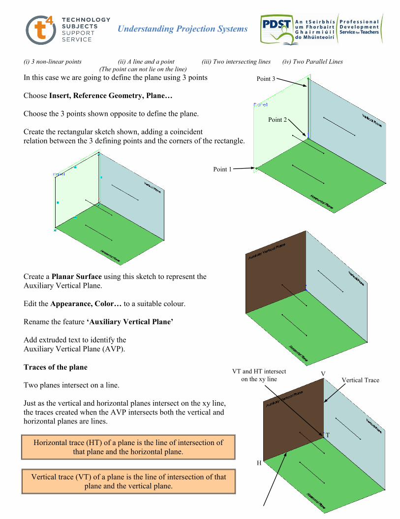
In this case we are going to define the plane using 3 points
Choose Insert, Reference Geometry, Plane…
Choose the 3 points shown opposite to define the plane.
Create the rectangular sketch shown, adding a coincident
relation between the 3 defining points and the corners of the rectangle.
Create a Planar Surface using this sketch to represent the
Auxiliary Vertical Plane.
Edit the Appearance, Color… to a suitable colour.
Rename the feature ‘Auxiliary Vertical Plane’
Add extruded text to identify the
Auxiliary Vertical Plane (AVP).
Traces of the plane
Two planes intersect on a line.
Just as the vertical and horizontal planes intersect on the xy line,
the traces created when the AVP intersects both the vertical and
horizontal planes are lines.
Point 1
Point 2
Point 3
Horizontal trace (HT) of a plane is the line of intersection of
that plane and the horizontal plane.
Vertical trace (VT) of a plane is the line of intersection of that
plane and the vertical plane.
H
T
V Vertical Trace
VT and HT intersect
on the xy line
Understanding Projection Systems
- 22 -
Choose Right View
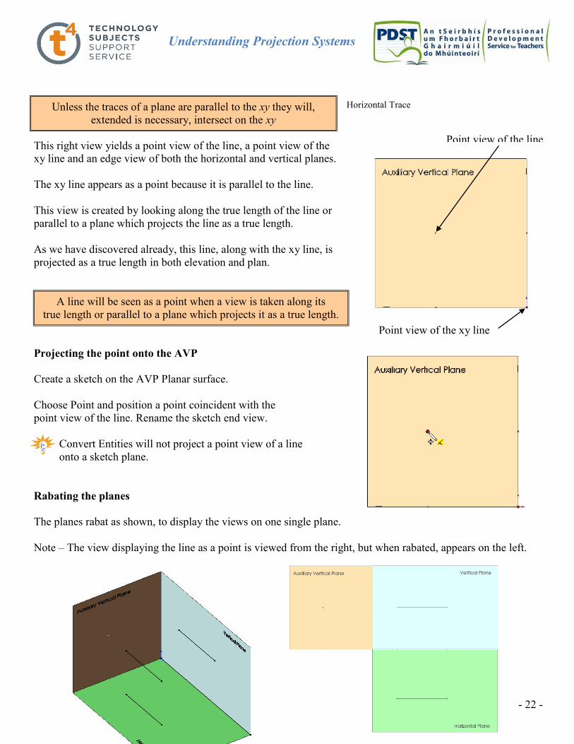
This right view yields a point view of the line, a point view of the
xy line and an edge view of both the horizontal and vertical planes.
The xy line appears as a point because it is parallel to the line.
This view is created by looking along the true length of the line or
parallel to a plane which projects the line as a true length.
As we have discovered already, this line, along with the xy line, is
projected as a true length in both elevation and plan.
Projecting the point onto the AVP
Create a sketch on the AVP Planar surface.
Choose Point and position a point coincident with the
point view of the line. Rename the sketch end view.
Convert Entities will not project a point view of a line
onto a sketch plane.
Rabating the planes
The planes rabat as shown, to display the views on one single plane.
Note – The view displaying the line as a point is viewed from the right, but when rabated, appears on the left.
A line will be seen as a point when a view is taken along its
true length or parallel to a plane which projects it as a true length.
Point view of the line
Point view of the xy line
Horizontal Trace Unless the traces of a plane are parallel to the xy they will,
extended is necessary, intersect on the xy

Understanding Projection Systems
- 23 -
Line co-incident with the vertical plane
We wish to edit the co-ordinates of the line so that it sits on the vertical plane but remains the same height above
the ground.
Endpoint 1 Endpoint 2
Which of the co-ordinates do we change?
The Z co-ordinate refers to the distance away from the vertical plane.
Changing these values to zero will position the line on the vertical plane.
Hide the Auxiliary Vertical Plane and text by right clicking on the
feature and selecting Hide.
The line is now positioned on the vertical plane.
Choose Front view.
Because the lines distance above the ground has not changed the
elevation appears unchanged.
The line is contained on the vertical plane, perpendicular to the line of vision and therefore appears as
a true length
On initial examination it looks as though the projection of the line
onto the horizontal plane has disappeared. However on closer
inspection we can see that it is coincident with the XY line.
Choose Top View.
In plan the line will coincide with the XY line or the edge view of
vertical plane.
Because the line is contained on the vertical plane then it will
coincide with the edge view of that plane in plan.
Because the object is zero distance in front of the vertical plane,
The distance of the object above the horizontal plane is
equal to the distance of the front view above the xy line

Understanding Projection Systems
- 24 -
i.e. contained on the plane, then it will be zero distance below the XY line.
End View of the line
Show the AVP and the AVP text by right clicking the feature
and selecting Show.
The projection of the line onto the AVP appears as a point,
on the vertical trace.
End View of the line
Choose Right View
In choosing the right view we are looking along the true length
of the line. Therefore the line appears as a point.
The vertical line containing the point not only represents
the edge view of the vertical plane but also the end view
of the vertical trace of the AVP.
Activity – Edit the coordinates of the line to position the line on the horizontal plane parallel to the
vertical plane. Investigate the projections of this line in elevation, plan and end view, the line as a true
length and point view.
Hide the AVP and AVP text. Delete the sketch End View.
The distance of the object in front of the vertical plane
is equal to the distance of the top view in front of the XY line Projection of the line on
the AVP, contained on the
vertical trace
Edge view of the
Horizontal Plane
Edge view of the
Vertical Plane and
end view of the
vertical trace

Understanding Projection Systems
- 25 -
Line parallel to the horizontal plane inclined to the vertical plane.
Edit the coordinates of the line to reflect those below.
Endpoint 1 Endpoint 2
The Y co-ordinate values are equal therefore the line will
be parallel to the horizontal plane.
The Z co-ordinate values differ therefore the line will not be
parallel but inclined to the vertical plane.
True length of the line.
If we examine the projected sketches in elevation we discover that they
project as two different lengths; 60mm in elevation and 67.08 in plan. Why?
The line is parallel to the horizontal plane and projects in plan as a true length.
However, the line is inclined to the vertical plane and when projected will
not appear as a true length but smaller. This reduction in size in elevation
is known as foreshortening.
If the true length is set against the foreshortened distance, the distance
that one point is in front of the other may be established.
A line will be seen as a true length when it is parallel to the
projection plane it is projected on to.
One endpoint of the line is
this distance further away
from the vertical plane than
the other.
Projections of line in elevation.
Projections of line in plan.
Understanding Projection Systems
- 26 -
Point view of the line
Select Right View. The line no longer appears as a point in the end view because we are no longer projecting
along the true length of the line.
Is the line a true length in the end view.
No, the line is not parallel to the AVP and will therefore not project as a true length. It will appear
foreshortened.
In order to get a point view of the line we must setup a view which is looking along the true length of the line.
To achieve this we must setup a plane which is perpendicular to this line of vision i.e. perpendicular to the line.
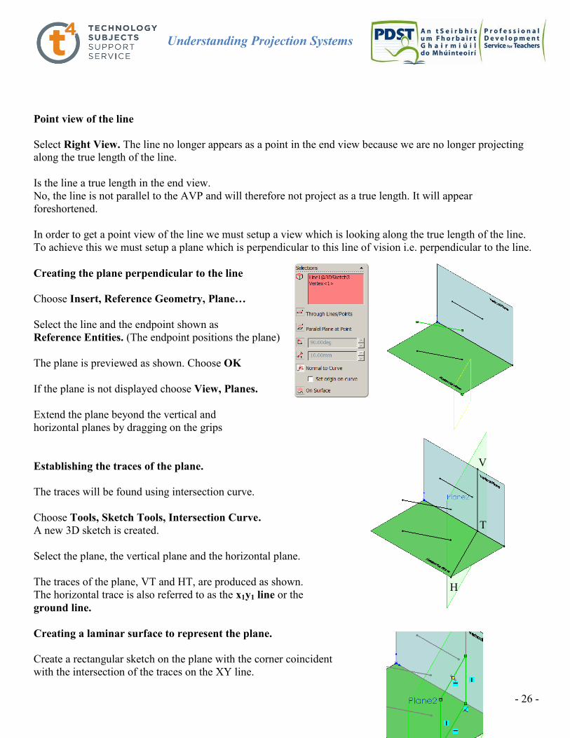
Creating the plane perpendicular to the line
Choose Insert, Reference Geometry, Plane…
Select the line and the endpoint shown as
Reference Entities. (The endpoint positions the plane)
The plane is previewed as shown. Choose OK
If the plane is not displayed choose View, Planes.
Extend the plane beyond the vertical and
horizontal planes by dragging on the grips
Establishing the traces of the plane.
The traces will be found using intersection curve.
Choose Tools, Sketch Tools, Intersection Curve.
A new 3D sketch is created.
Select the plane, the vertical plane and the horizontal plane.
The traces of the plane, VT and HT, are produced as shown.
The horizontal trace is also referred to as the x1y1 line or the
ground line.
Creating a laminar surface to represent the plane.
Create a rectangular sketch on the plane with the corner coincident
with the intersection of the traces on the XY line.
H
T
V

Understanding Projection Systems
- 27 -
Add a coincident relation between the corners of the rectangle and the
endpoints of the traces as shown.
Create a Planar Surface using this sketch to represent the
Auxiliary Vertical Plane.
Edit the Appearance, Color… to a suitable colour
Reduce the transparency to 0.5.
Rename the feature ‘Auxiliary Vertical Plane 2’
Add extruded text to identify Auxiliary Vertical Plane 2.
Hide the plane
The plane generated is a vertical plane and is referred to
as an Auxiliary Vertical Plane. It is at right angles
to the horizontal plane but inclined to the vertical plane.
The vertical trace is vertical because the line of intersection
between two vertical planes is a vertical line.
Choose Top View
The AVP appears as an edge. Why?
Because the VT is vertical, it appears as a true length in elevation.
When we choose a plan view we are looking along
the true length of the VT and see it as a point.
Because the VT is contained on the AVP it
appears as an edge
In the top view the vertical plane and the auxiliary vertical plane are presented as edge views therefore, the true
angle between them is displayed.
The edge view of the plane also represents the plan view of the horizontal trace.
AVP as an
edge and plan
view of the HT
and the x1y1
AVP as an
edge and plan
view of the HT
Point view of
the VT
True inclination of
the AVP with the VP
A plane will appear as an edge when a line
contained on it projects as a point
When the VT is perpendicular to the xy, the inclination of the plane to the
vertical plane is given by the angle between the horizontal trace and the xy

Understanding Projection Systems
- 28 -
Select the Auxiliary Vertical Plane
Choose Normal To.
This will give a normal to view from behind the plane.
Choose Normal To again to view from the opposite side.
The line is viewed as a point because we are looking along the
true length of the line projecting onto a plane at right angles to it.
Create a sketch using Auxiliary Vertical Plane 2.
Position a point co-incident with the point view of the line.
Rename the sketch Auxiliary Elevation
Note the distance of the line above the xy in both the elevation and auxiliary elevation are equal.
The auxiliary projection is shown orthographically by rabating the auxiliary vertical plane about t he x1y1
An auxiliary elevation is a projection on any auxiliary
vertical plane not parallel to the vertical plane.
The distances of all elevations of the same point from the corresponding ground lines are equal.
xy line
(Ground line)
True length
of the line
Point view
of the line
x1y1 line
(Ground line)

Understanding Projection Systems
- 29 -
Save the file as Auxiliary Elevation
Delete the following features and save the file as Auxiliary Plan
Line parallel to the vertical plane inclined to the horizontal plane.
Edit the coordinates of the line to reflect those below.
The Z co-ordinate values are equal therefore the line will
be parallel to the vertical plane.
The Y co-ordinate values differ therefore the line will not be
parallel, but inclined, to the horizontal plane.
Which view will project the line as a true length?
The line is parallel to the vertical plane and therefore will
appear as a true length in elevation.
The line is inclined to the horizonatal plane and when
Projected will appear foreshortened in the plan view.
The apparent length of a foreshortened line is referred to
as the plan distance
If the true length is set against the plan distance, the height of one endpoint relative to the other is given.
A line will be seen as a true length when it is parallel to the
projection plane it is projected on to.
Height of one point
relative to the other
Understanding Projection Systems
- 30 -
Point view of the line
In order to get a point view of the line we must setup a view which is looking along the true length of the line.
To achieve this we must setup a plane which is perpendicular to this line of vision i.e. perpendicular to the line.
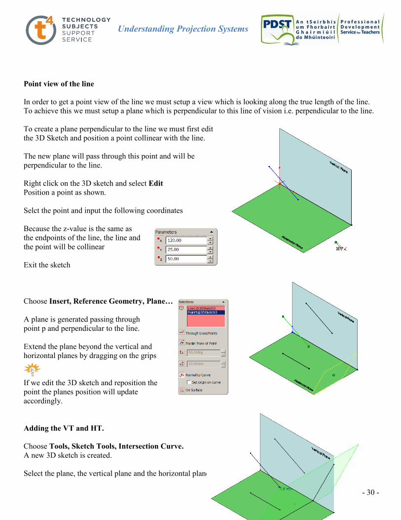
To create a plane perpendicular to the line we must first edit
the 3D Sketch and position a point collinear with the line.
The new plane will pass through this point and will be
perpendicular to the line.
Right click on the 3D sketch and select Edit
Position a point as shown.
Selct the point and input the following coordinates
Because the z-value is the same as
the endpoints of the line, the line and
the point will be collinear
Exit the sketch
Choose Insert, Reference Geometry, Plane…
A plane is generated passing through
point p and perpendicular to the line.
Extend the plane beyond the vertical and
horizontal planes by dragging on the grips
If we edit the 3D sketch and reposition the
point the planes position will update
accordingly.
Adding the VT and HT.
Choose Tools, Sketch Tools, Intersection Curve.
A new 3D sketch is created.
Select the plane, the vertical plane and the horizontal plane.

Understanding Projection Systems
- 31 -
The traces of the plane, VT and HT, are produced as shown.
The vertical trace is also referred to as the x1y1 line
Creating a laminar surface to represent the plane.
Create a rectangular sketch on the plane with the corner coincident
with the intersection of the traces on the XY line.
Add horizontal and vertical relations between the corners of the
rectangle and the endpoints of the traces as shown.
Create a Planar Surface using this sketch to represent the
Inclined Plane.
Edit the Appearance, Color… to a suitable colour
Reduce the transparency to 0.5.
Rename the feature ‘Inclined Plane’
Hide the plane
The plane generated is an inclined plane.
The horizontal trace is contained on the horizontal plane and
therefore appears as a true length.
The horizontal trace is perpendicular to the xy line.
In the front view the HT appears as a point, as we are looking along
its true length.
The horizontal trace is contained on the inclined plane and the plane
therefore appears as an edge.
In the front view the horizontal plane and the inclined plane
are presented as edge views therefore, the true angle between
them is displayed.
The edge view of the plane also represents the front view of the vertical trace.
An inclined plane is perpendicular to the vertical plane and
inclined to the horizontal plane.
A plane will appear as an edge when a line
contained on it projects as a point
Point view of
the HT True Inclination of
the Inclined Plane
When the HT is perpendicular to the xy, the inclination of the plane to the
horizontal plane is given by the angle between the vertical trace and the xy
VT or x1y1
HT Point view of
the line
V
T
H

Understanding Projection Systems
- 32 -
The pictorial view below shows the line with its three projections.
The rabatment of the planes results in the views shown on the right. The point view is rabated about the x1y1.
This view is called the Auxiliary Plan
x1y1
V
T
H
x1
y1
xy line
(Ground line)
True length
of the line
Point view
of the line
x1y1 line
(Ground line)
The distances of all plans of the same point from the corresponding ground lines are equal.