Embed Size (px)
Citation preview

PH2031
UNDERSTANDING REFLECTION
NCEA LEVEL 2
2012/1
2 PH2031 © TE AHO O TE KURA POUNAMU
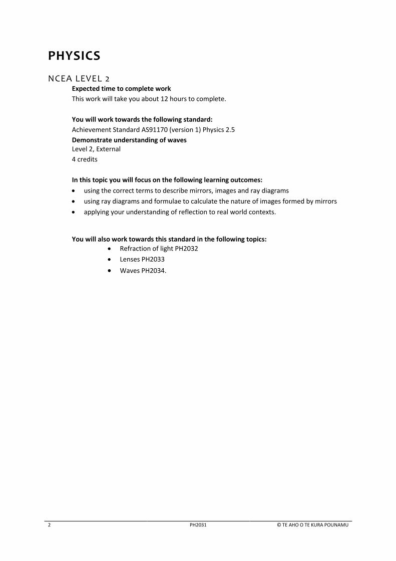
PHYSICS
NCEA LEVEL 2 Expected time to complete work
This work will take you about 12 hours to complete.
You will work towards the following standard:
Achievement Standard AS91170 (version 1) Physics 2.5
Demonstrate understanding of waves Level 2, External
4 credits
In this topic you will focus on the following learning outcomes:
using the correct terms to describe mirrors, images and ray diagrams
using ray diagrams and formulae to calculate the nature of images formed by mirrors
applying your understanding of reflection to real world contexts.
You will also work towards this standard in the following topics:
Refraction of light PH2032
Lenses PH2033
Waves PH2034.
CONTENTS
© TE AHO O TE KURA POUNAMU PH2031 3
CONTENTS
1 Reflection of light 5
2 Concave mirrors 10
3 Concave mirror ray diagrams 16
4 Using concave mirrors 24
5 Concave mirror calculations 33
6 Convex mirrors 41
7 Convex mirror calculations 49
8 Calculations and significant figures 54
9 Teacher-Marked Assignment 59
10 Answer Guide 60

4 PH2031 © TE AHO O TE KURA POUNAMU
HOW TO DO THE WORK
When you see:
Complete the activity.
Check your answers in the Answer Guide at the back of this booklet.
Use the Topic webpage or the Internet
This symbol indicates an alternative activity for students who cannot complete an online activity.
Hands-on activity. Complete these practical activities to strengthen your learning.
You will need:
a pen or pencil
a ruler and a protractor
a computer with internet access
and access to the topic web page
concave mirror 10 cm focal
length*
LED torch*
convex mirror 10 cm focal length*
a white
2 pieces of blu-tack/plasticene *
*contained in the Light equipment box
supplied to eligible Te Kura students
Resource overview
This topic provides an introduction to reflection. You will get most out of your studies if you use the write-in booklet alongside a computer with an Internet connection, using the Topic webpage. It is possible to study this topic using just the booklet if you read the explanations and the answers very carefully. Interesting extras, which are not essential for passing the NCEA Achievement Standard, are marked in lilac boxes like this. You may skip these if you are short of time. Mark your own answers, using the Answer guide. Try to think critically about the physics involved. Computer-based activities Te Kura’s Online Teaching and Learning site, OTLE, has many supporting materials that will aid your learning. Log on to this site to enhance your understanding of the subject matter. The Physics Education Technology (PhET) teaching simulations are some of the most powerful learning tools you can use on a computer. Activities that use these simulations appear in many Te Kura physics topics. You can run these simulations online or install them on your computer.
To run a simulation online:
click on the link on the OTLE Topic webpage or use a search engine such as Google to search for ‘PhET’ and the name of the simulation.
To install PhET on your computer:
download and install PhET from http://phet.colorado.edu/get_phet/full_install.php (this is recommended if you don’t have fast Internet) or install PhET from a disc – ask your teacher to send a disc to you.
1A

REFLECTION OF LIGHT
© TE AHO O TE KURA POUNAMU PH2031 5
1 REFLECTION OF LIGHT
LEARNING INTENTIONS In this lesson you will learn to:
use the terms: reflection, virtual image, real image, magnification, divergent rays, convergent rays
describe the characteristics of the image formed by a plane mirror. INTRODUCTION We cannot imagine life without either sunlight or artificial light. Light is something most of us take
for granted every day. It is there throughout our lives; it will always be there in the familiar patterns
we experience as we grew up.
What is light? This seems like a silly question at first, but after some thought most of us will agree we
do not know much about light. We know that it comes out of the Sun, lets us see things, and makes
us warm. In this lesson we look at what light is and at some of its interactions with physical objects.
WHAT IS LIGHT? We see light as colour and brightness. It is actually a form of energy, specifically radiant energy. In physics it is called electromagnetic radiation – a radiation that is partly electric and partly magnetic. Light travels at 300 million meters in one second, which is 3.0 x 10⁸ m s-1. It takes 8 minutes for light to travel from the Sun to the Earth. It takes one second for light reflected off the Moon to reach the Earth.
A ray of light is a very fine line of light. We use a straight line with an arrow to represent a ray of light. The arrow shows the direction in which the light energy is travelling.
A beam of light is a bundle of rays. A beam can be parallel, convergent or divergent.
Divergent beam – rays are
travelling away from a
point
Convergent beam –
rays are travelling
towards a point
Parallel beam – all rays are
parallel
ray of light
Ray of light

6 PH2031 © TE AHO O TE KURA POUNAMU
REFLECTION OF LIGHT You must look directly at an object to see it. This is because some of the light from the object has to enter your eyes for it to be seen. Reflection causes the light to change direction. We see things because they reflect light into our eyes. We see the Moon at night because light from the Sun is reflected off the Moon. Without reflection we can’t see anything.
You can read this text because the light is reflected off the text into your eyes. The light
changes direction during reflection to reach your eyes.
REFLECTION IN A MIRROR
When you see yourself in a mirror the light from you hits the mirror and bounces off it. This process is called reflection. In physics, your reflection is your image and you are the object that causes this image.
You will notice the following things when you see yourself in a plane (flat) mirror:
Your reflection and you are in the same orientation. So if you are standing upright, the image is
upright. If you are standing upside down, the image is also upside down.
Your reflection from the mirror is the same distance away from the mirror as you are. The
distance of the image from the mirror is known as the image distance ( ). The distance of the
object (you) from the mirror is known as the object distance ( ).
For a plane mirror the object distance ( ) and image distance ( ) are equal.
Your reflection is the same size as you. That is, the height or size ( ) of the image is the same as
the height or size ( ) of the object.
The comparative size of the image in relation to the object is called the magnification ( ). In this
case, the value of the magnification, , because the object size is the same as the image size.
The magnification can be calculated using
The object is the actual thing that is forming the image
The image is the ‘something’ which is seen which looks like the object
Mirror

REFLECTION OF LIGHT
© TE AHO O TE KURA POUNAMU PH2031 7
REAL AND VIRTUAL IMA GES When you watch a movie in a theatre the light from the projector falls on the screen to form an
image. In physics, we call this image a real image. It is real because the light rays are focused onto
the screen to produce images. A real image can always be captured on a screen and exists even
without an observer.
The opposite of a real image is a virtual image; for example, the image in a flat mirror. A virtual
image is a reproduction of an object that is formed when the light rays do not actually meet beyond
the mirror. A virtual image exists only within the brain of the observer. When you look at a flat
mirror, you see a virtual image that appears to be behind the mirror. But nothing actually exists at
that point (except perhaps a wall). A virtual image cannot be projected on a screen.
SEEING VIRTUAL IMAGE S
How can you see something that isn’t there? Find out more using the links on the Topic webpage.
QUICK QUIZ
A clown looks at his image in a floor-to-ceiling mirror. The diagram shows the clown on the left and his image on the right. The clown’s right foot is 1.2 m from the mirror. 1. How far is the image of the right foot from the mirror?
2. If the clown is 1.6 m tall, what is the size of his image?
3. The clown now moves away twice as far from the mirror as he was before. Explain how this
affects: a. the distance of the image from the mirror
b. the magnification of the image
4. Is the image real or virtual? Explain your answer.
1B
1A

8 PH2031 © TE AHO O TE KURA POUNAMU
5. When the clown looks at a different mirror, which is slightly curved, the image he sees is only 1.2 m tall. Calculate the magnification of the image.
Check your answers.
LAWS OF REFLECTION In the diagram, the ray of light approaching the mirror is called the incident ray. The ray of light that leaves the mirror is known as the reflected ray. At the point of incidence where the ray strikes the mirror, a line is drawn at 90° to the surface of the mirror. This line is known as a normal line. The normal line divides the angle between the incident ray and the reflected ray into two equal angles. The angle between the incident ray and the normal is known as the angle of incidence. The angle between the reflected ray and the normal is known as the angle of reflection.
QUICK QUIZ
1. In the above diagram, if the angle between the mirror and the incident ray is 30o, calculate the angle of reflection.
2. A ray of light strikes a plane mirror with an angle of
incidence of 60o. a. What is the angle between the incident and
reflected rays?
b. What is the angle between the reflected ray
and the mirror?
Check your answers.
1C
The law of reflection states that when a ray of light reflects off a surface, the angle of
incidence is equal to the angle of reflection.
plane mirror
incident ray reflected ray
angle of
incidence equals angle of
reflection

REFLECTION OF LIGHT
© TE AHO O TE KURA POUNAMU PH2031 9
USING PLANE MIRRORS
Plane mirrors are an important part of much technical equipment. They can also provide lots of entertainment. Have a look at the Topic webpage to find out more.
KEY POINTS
A ray of light is a fine line of light. A beam is a collection of rays. A beam of light can be a
convergent, divergent or parallel beam.
Magnification of an image can be calculated using the formula
An image can be virtual or real. Rays of light travel from a real image; they just
appear to come from a virtual image.
The law of reflection states that when a ray of light reflects off a surface, the angle of
incidence is equal to the angle of reflection.
1D

10 PH2031 © TE AHO O TE KURA POUNAMU
2 CONCAVE MIRRORS
LEARNING INTENTIONS In this lesson you will learn to:
describe mirrors using the terms: concave, centre of curvature, radius of curvature, principal focus
outline the characteristics of an image formed by a concave mirror. INTRODUCTION The mirrors that you use every day in your
home have flat surfaces. You might have
noticed that the mirrors that hang in shops to
deter shop lifting have curved surfaces. Curved
mirrors produce the effect of enlarging or
shrinking the image. There are two types of
curved mirrors: concave and convex. In this
lesson we are going to look at how a concave
mirror reflects light to form an image.
A spoon reflects on both sides. The spoon on the left is showing its convex side. The spoon on the right is showing its concave side.
WHAT IS A CONCAVE MIRROR? A concave mirror can be imagined as a portion
of a glass sphere. The outside of the cut-away
section of the sphere is silvered to form a
reflecting surface, so a concave mirror like this
is a type of spherical mirror.
When parallel rays shine towards a concave
mirror, they reflect and focus (converge) onto a
point.
For this reason a concave
mirror is also called a
converging mirror.
When the rays are parallel
to the principal axis (the
dashed line), the converge
at the principal focus, F.
The point C is the centre of the sphere from which the mirror is cut – it is known as the centre of
curvature. The distance between the centre of the mirror to point C is the radius of curvature (R) of
the mirror.
focal
length
silvered
surface
C
F
Glass sphere
Concave
mirror
The point F is called
the principal focus.
Focal length ( ) of a
concave mirror is the
distance from the
mirror along the
principal axis to F, the
principal focus.

CONCAVE MIRRORS
© TE AHO O TE KURA POUNAMU PH2031 11
Practically, the focal length ( ) is always half the length of the radius of curvature.
HANDS-ON ACTIVITY: FINDING FOCAL LENGTH
What you need:
a concave mirror*
an LED torch*
a piece of white card*
blu-tack or plasticene* * provided to eligible Te Kura students in an equipment kit. What you do: 1. To make a screen, use blu-tack to stick a piece of white card
to the end of a small cardboard box or onto the side of a cup.
2. Use blu-tack to hold the concave mirror upright on the table. 3. Place the torch about 150 cm from the mirror and turn the switch on. 4. Place the screen about 15 cm from the mirror and to one side of it, with the white side facing
the mirror. Turn the mirror slightly sideways towards the screen so that the reflected light falls on the screen.
5. Move the screen slowly away from the mirror until you can see a clear image of the light on the screen.
6. Record the distance of the image from the mirror.
The focal length is ________________________
Check your answers.
HOW DOES THE IMAGE FORM? The light rays from a distant object arrive parallel at the mirror. After they are reflected from the mirror they will focus on the focal plane, creating a real image of the distant object.
In this diagram the rays are parallel to the principal axis, so they converge at F, the principal focus.
2A
Focal
plane
12 PH2031 © TE AHO O TE KURA POUNAMU
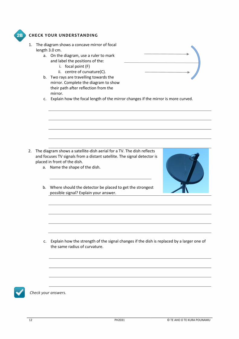
CHECK YOUR UNDERSTANDING
1. The diagram shows a concave mirror of focal length 3.0 cm.
a. On the diagram, use a ruler to mark and label the positions of the:
i. focal point (F) ii. centre of curvature(C).
b. Two rays are travelling towards the mirror. Complete the diagram to show their path after reflection from the mirror.
c. Explain how the focal length of the mirror changes if the mirror is more curved.
2. The diagram shows a satellite-dish aerial for a TV. The dish reflects and focuses TV signals from a distant satellite. The signal detector is placed in front of the dish.
a. Name the shape of the dish.
b. Where should the detector be placed to get the strongest
possible signal? Explain your answer.
c. Explain how the strength of the signal changes if the dish is replaced by a larger one of
the same radius of curvature.
Check your answers.
2B

CONCAVE MIRRORS
© TE AHO O TE KURA POUNAMU PH2031 13
HANDS-ON ACTIVITY: IMAGES IN CONCAVE MI RRORS
What you need:
a concave mirror*
an LED torch*
a piece of white card*
blu-tack or plasticene*
a ruler or a measuring tape * provided to eligible Te Kura students in an equipment kit. What you do: 1. To make the paper screen, stick a piece of white paper to the end of
a small cardboard box or on the side of a cup. 2. Use blu-tack to support the concave mirror upright on the table. 3. Place the torch about 70 cm from the mirror so that the two bulbs are near the table surface and
the third one is above them, making a triangular shape. Turn the torch on. 4. Place the screen about 15 cm away and to one of the mirror, with the white side facing the
mirror. Turn the mirror slightly sideways towards the screen so that the reflected light falls on the screen.
5. Move the screen slowly away from the mirror until you can see a clear image of the light on the screen.
6. Record the distance of the image from the mirror in the table below. Also record the image size and its orientation.
7. Repeat step 6 for the other distance shown in the table.
Distance of the light from the mirror (cm).
Distance of the image from the mirror (cm).
Image size (larger / smaller / same size)
Nature of the image:
(upright / upside down)
60
50
40
30
Use your results to answer the following questions. 8. Make a statement about how the size of the image changes as the object gets closer to the
mirror.
9. Make a statement about how the object distance and the image distance are related.
Check your answers.
2C

14 PH2031 © TE AHO O TE KURA POUNAMU
PARABOLIC MIRRORS A major problem with large spherical mirrors is that parallel rays from a distant point do not focus at
one point, as shown in the diagram. You cannot use large spherical mirrors in optical instruments
such as telescopes – this spherical aberration makes the image blurred.
Spherical aberration – lack of clear focus Parabolic mirror – sharp focus
Spherical aberration can be remedied by using a parabolic mirror instead. A parabolic mirror brings
all rays to the same focus whether or not they are close to the principal axis. Astronomical reflecting
telescopes are always parabolic in shape.
CAR HEADLIGHT BEAM A car’s headlight is a good example of an object placed at the focal length. The headlight takes the light emitted by a bright lamp and reflects it forward so that it illuminates the road as far ahead as possible. This is achieved by placing the bulb at the focal point of a parabolic reflector. The rays from the bulb are reflected at different angles so they end up pointing parallel to each other. The parallel beam of rays will illuminate distant objects.
SOLAR COOKERS A solar cooker uses a parabolic reflecting surface and the Sun’s energy to cook food. Rays from the Sun are reflected to a focus at the focal point. The cooking pot is placed at the focal point. The pot is black so that it absorbs as much energy as possible.
Parabolic mirror

CONCAVE MIRRORS
© TE AHO O TE KURA POUNAMU PH2031 15
MAKE YOUR OWN SOLAR COOKER
Find out how to build your own solar cooker using cheap scrap materials. The links are on the Topic webpage.
TELESCOPES The Hubble Space Telescope (HST) used two of these giant curved mirrors to help us understand the cosmos. The primary mirror of the telescope has a diameter of 2.4 m and weighs about 825 kg. Until recently, most astronomers considered the universe to be about 3600 light years in extent. Thanks to the Hubble Telescope, astronomers have now seen objects 13 billion light years away in a universe that contains hundreds of billions of galaxies.
Polishing the primary mirror of the HST in March 1979
MIRRORS IN TELESCOPE S
Find out more about the construction and design of mirrors used in telescopes using the links on the Topic webpage.
KEY IDEAS
A concave mirror is the shape of a section of a sphere. The outer surface of the spherical surface is silvered so that the inner spherical surface reflects light.
The central axis is the radius of the sphere and the centre of the sphere is the centre of curvature of the mirror.
The midpoint between the centre of the mirror and the centre of the sphere which the mirror forms a part of is called the principal focus or the focal point.
The focal length is half the radius of curvature.
Rays travelling parallel to the principal axis converge at the principal focus.
2E
2D

16 PH2031 © TE AHO O TE KURA POUNAMU
3 CONCAVE MIRROR RAY DIAGRAMS
LEARNING INTENTIONS In this lesson you will learn to:
draw ray diagrams for concave mirrors to locate the image
identify the characteristics of an image from a ray diagram.
INTRODUCTION In lesson 2 you studied the images formed by a concave mirror. In this lesson you will learn to explain how these images are produced.
Think of a curved mirror as consisting of a very large number of small plane mirrors oriented at slightly different angles. The laws of reflection that apply to plane mirrors also apply to concave mirrors. The angle of incidence is equal to the angle of reflection at every point.
CONCAVE MIRRORS AND THE LAWS OF REFLECTION
All curved mirror ray diagrams begin with the base drawing shown here. It contains a principal axis and the principal focus F.
A ray of light that travels along the normal towards a plane mirror will reflect back on the same path. The angle of incidence is zero; therefore the angle of reflection is also zero.
A concave mirror acts the same way. The principal axis is a normal line to the concave mirror. So a ray of light that travels along the principal axis towards the mirror will reflect back on the same path because it must obey the law of reflection.
Centre of
curvature
Principal axis
Reflecting surface
Principal focus,
F

CONCAVE MIRROR RAY DIAGRAMS
© TE AHO O TE KURA POUNAMU PH2031 17
RULES FOR RAY DIAGRAMS A ray diagram is a useful tool for determining the location, size, orientation, and type of image formed by a mirror. To construct a ray diagram we need to follow some rules. The following five rules are derived by observing how a ray of light interacts with a convex mirror.
Rule 1 An incident ray of light that travels along the principal axis is reflected back on the same path.
Rule 2 An incident ray that travels parallel to the principal axis is reflected back through the principal focus.
Rule 3 An incident ray passing through the principal focus is reflected in such a way that it travels parallel to the principal axis. (This is the reverse of Rule 2, which shows that the path of the light is reversible)
Rule 4 An incident ray that strikes the centre of the mirror at a certain angle to the principal axis is reflected from the mirror at the same angle.
Rule 5 An incident ray that travels through the centre of curvature is reflected back along the same path. (This is the law of reflection.)
CONSTRUCTION OF RAY DIAGRAMS TO LOCATE THE IMAGE We can use the rules described above to construct ray diagrams to locate the image formed when an
object is placed in front of a concave mirror.
You must use Rule 1 for all ray diagrams and you may choose any other two rules to complete the
diagram. The following example shows how to construct a ray diagram step by step.

18 PH2031 © TE AHO O TE KURA POUNAMU
Example: An object 3.0 cm high is placed 12 cm in front of a concave mirror of focal length 5.0 cm. Construct a scale ray diagram to find the nature, size and position of the image produced by the mirror.
Here we are using a grid which serves as a scale to construct the ray diagram. We can also use a scaled diagram without the grid. The scale is used so that we can represent the actual situation on the paper. The selection of the scale depends on the situation. If the real situation uses large distances we scale down to fit onto the paper. If it is too small we scale up so that we can represent the situation with accuracy.
Step 1 – set the axes
Step 2 – add the object
C F
Object
When you construct a ray diagram, the vertical scale for the diagram does not have to be the same as the horizontal scale. This is particularly useful if a tiny object such as a small insect is to be viewed in a mirror with a large focal length and you need to draw a ray diagram to find the image.
Now we draw the object in front of the mirror line. The object is usually represented as a small vertical arrow. Here we use the same scale for horizontal and vertical distances, so it is 12 squares from the centre of the mirror and 3 squares high.
C F
a. First we draw a base diagram with a vertical line – called the mirror line – which
represents the reflecting surface. Although the mirror surface is curved, the mirror line
is a straight vertical line. A ray diagram tends to use a large mirror line to represent the
mirror so that there is very little loss of accuracy.
b. Now we draw a principal axis at the middle of the mirror line and at 90° to it. A small
sketch of a curved mirror symbol is drawn at the intersection of the two axes to indicate
the type of mirror being used.
c. The next step is to locate the mirror’s focal point F, and its centre of curvature C on the
principal axis to scale. In this case we use 1 cm = 1 square. So the focus F is 5 squares
from the mirror, and the centre of curvature C is 10 squares from the mirror.
mirror line
CONCAVE MIRROR RAY DIAGRAMS
© TE AHO O TE KURA POUNAMU PH2031 19
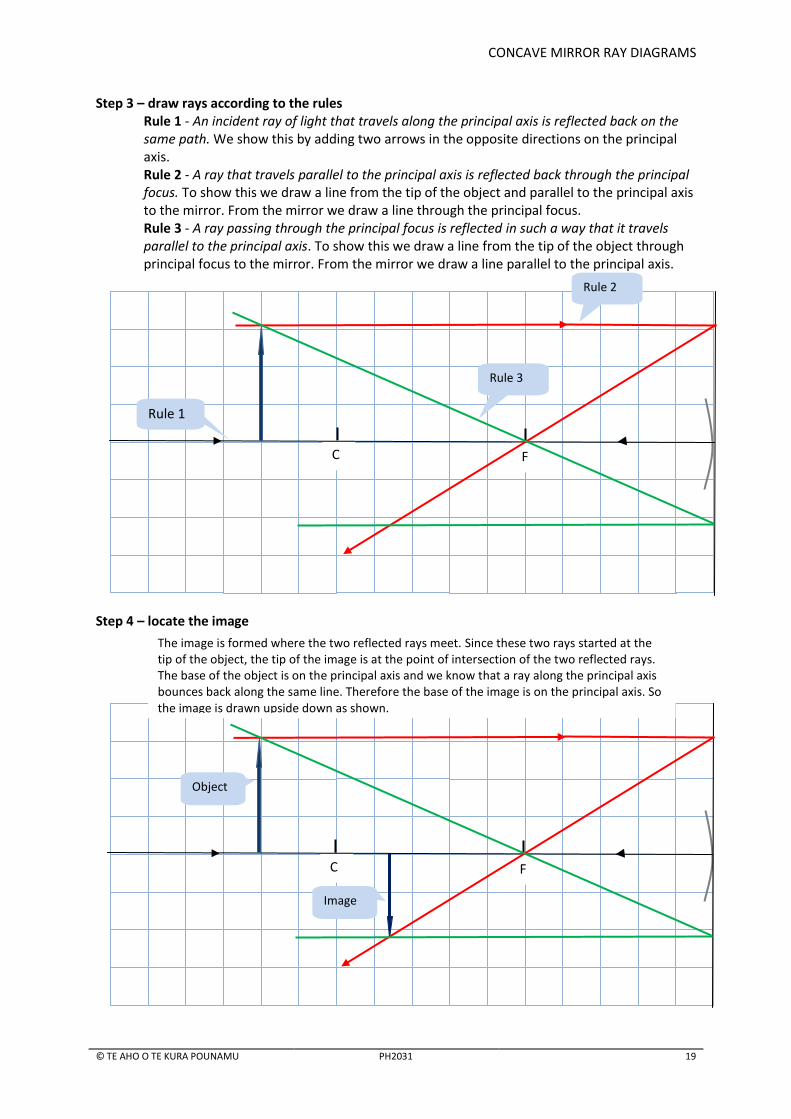
Step 3 – draw rays according to the rules Rule 1 - An incident ray of light that travels along the principal axis is reflected back on the same path. We show this by adding two arrows in the opposite directions on the principal axis. Rule 2 - A ray that travels parallel to the principal axis is reflected back through the principal focus. To show this we draw a line from the tip of the object and parallel to the principal axis to the mirror. From the mirror we draw a line through the principal focus. Rule 3 - A ray passing through the principal focus is reflected in such a way that it travels parallel to the principal axis. To show this we draw a line from the tip of the object through principal focus to the mirror. From the mirror we draw a line parallel to the principal axis.
Step 4 – locate the image
C F
Object
Image
The image is formed where the two reflected rays meet. Since these two rays started at the tip of the object, the tip of the image is at the point of intersection of the two reflected rays. The base of the object is on the principal axis and we know that a ray along the principal axis bounces back along the same line. Therefore the base of the image is on the principal axis. So the image is drawn upside down as shown.
C F
Rule 2
Rule 3
Rule 1

20 PH2031 © TE AHO O TE KURA POUNAMU
DESCRIBING THE IMAGE The image is described by its:
Nature – Is the image real or virtual? Because the reflected rays actually meet to produce the image, it is a real image. We show this by drawing the image with continuous lines. A virtual image is drawn using broken lines.
Position – Where is the image in relation to the mirror? The image is about 8.6 squares from the mirror. The scale we used is 1 square = 1 cm, so the image position is 8.6 cm from the mirror.
Orientation- Is the image upright or upside down (inverted)? The image is upside down.
Size – Is the image magnified (bigger than the object) or diminished (smaller than the object)? In this case the image is diminished because it is smaller than the object.
Magnification – How big is the image compared to the object? The distance from the object to the mirror is the object distance, , and the distance from the mirror line to the image is the image distance, . The formula for magnification is:
There is no unit for magnification because it is a ratio, a quantity that compares two items
which are measured in the same unit.
C F
Object
Image
We can check the position of the image by using rule 4. A ray from the tip of the object to the centre of the mirror will reflect back in such a way that the angle of incidence and angle of reflection are the same. The incident ray started at the tip of the object which is 3 squares up, so the reflected ray should go through 3 squares below the object to make the angles equal.

CONCAVE MIRROR RAY DIAGRAMS
© TE AHO O TE KURA POUNAMU PH2031 21
How many significant figures does the answer need to have? Rounding of numbers in the answer is often required to ensure that an answer to a problem is not given to a higher level of accuracy than the data that was used in the problem. To avoid increased error in the calculation, it is also a good idea not to round until you have a final answer. In the example above, the data is given to 2 significant figures so the final answer is rounded to 2 significant figures too. (See lesson 8 for more details.)
MAGNIFICATION AND IMAGE SIZE We can use the magnification to calculate the size of the image.
From the equation for magnification:
This can be rearranged as:
This matches the value shown by the scale drawing on page 20.
RAY DIAGRAMS FOR CONCAVE MIRRORS
Use the links on the Topic webpage to access an applet which draws ray diagrams automatically while you move the object around. There are also helpful videos which show how these diagrams work.
OBJECT AT THE PRINCIPAL FOCUS In lesson 2 you learned how parallel rays of light are focused at the principal focus of a mirror and
how light diverging from the principal focus is reflected into a beam of parallel rays. These ideas are
used in satellite dishes and in car headlamps.
This diagram shows how the rules for curved mirrors apply for an object at the principal focus. No image is formed when an object is placed at the principal focus of a concave mirror because the reflected rays are in parallel, and parallel rays never converge at a point.
3A
C F

22 PH2031 © TE AHO O TE KURA POUNAMU
CHECK YOUR UNDERSTANDING
1. a. Complete the following ray diagram by drawing two rays from the tip of the object.
Locate the image. Scale: 1sq = 1cm.
b. Describe the nature, height and position of the image.
Nature:________________ height: ______________ position: ________________
c. Calculate the magnification of the image.
C F
3B

CONCAVE MIRROR RAY DIAGRAMS
© TE AHO O TE KURA POUNAMU PH2031 23
2. The diagram below shows an object placed on the centre of curvature of a concave mirror. The scale is 1 sq = 1 cm.
a. On the diagram, locate and label the position of the principal focus.
b. Complete the ray diagram by drawing two rays from the tip of the object to locate the
image. c. Draw a third ray to check the position of the image.
d. Describe the nature, height and the position of the image.
Nature:________________ height: __________________ position: ________________
e. Calculate the magnification of the image.
Check your answers.
KEY POINTS
An image is produced when an object is placed in front of a concave mirror.
The image can be real/virtual; magnified/diminished; upright/inverted.
We use a ray diagram to find the position of the image.
C

24 PH2031 © TE AHO O TE KURA POUNAMU
4 USING CONCAVE MIRRORS
LEARNING INTENTIONS In this lesson you will learn to:
draw scale diagrams to locate the image formed by a concave mirror
describe the characteristics of an image from a ray diagram for different object positions
explain how concave mirrors can be used for magnification.
INTRODUCTION In the previous lesson you used grids to draw ray diagrams. In this lesson you will practice drawing ray diagrams without using a grid. You will also learn more about the practical uses of concave mirrors.
SCALE DIAGRAMS The idea of a scale diagram is to show the real situation on paper. Choose an appropriate scale to
represent the real situation accurately. A scale of large ratio will result in a small diagram, thereby
sacrificing the accuracy. A scale of small ratio will result in a large diagram that might not fit onto
your page.
When constructing a ray diagram, the vertical scale for the object size does not have to be the same
as the horizontal.
Example: An object 3.0 cm high is placed 24 cm in front of a concave mirror of 8.0 cm focal length. Use a scale drawing to find the nature, size and position of the image formed.
Answer Step 1: Choose a scale
This page is about 21 cm wide, so a scale of 1 cm: 2 cm would be satisfactory for this
situation. This means that every 2 cm in the real situation is 1 cm in this drawing. Once you
have chosen a scale you should state it as: Scale: 1cm: 2cm
Step 2: Work out the size of each quantity given in the question The scale is 1:2. This means your drawing shows half the size of the real situation. So we
need to halve all given quantities in the question. The image height becomes 1.5 cm, the
focal length is 4.0 cm and the object distance is 12 cm in your diagram.
It is useful to make a rough sketch like the one below to visualise the situation before you
draw the actual scaled diagram.

USING CONCAVE MIRRORS
© TE AHO O TE KURA POUNAMU PH2031 25
Step 3: Construct the ray diagram using the scale Draw two sets of rays to locate the image.
Step 4: Describe the image Measure the height and distance of the image from the mirror and multiply them by the
scale factor. In this case we multiply the measured value by a factor of 2.
The image is:
12 cm in front of the mirror. A value of 11 to 13 cm is acceptable to accommodate
the drawing error.
1.5 (1.3 to 1.7) cm tall
real, inverted.
CHECK YOUR UNDERSTANDING
1. An object 2 cm high is placed 20 cm in front of a concave mirror of 12 cm focal length. a. Use a scale of 1 cm: 2 cm to draw a ray diagram to locate the image.
4A

26 PH2031 © TE AHO O TE KURA POUNAMU
b. Describe the nature, size and the position of the image.
Nature:________________ size: __________________ position: ________________
c. Calculate the magnification of the image.
2. An object 2 cm high is placed 30 cm in front of a concave mirror of 10 cm focal length.
a. Use a scale of 1 cm: 2 cm to draw a ray diagram to locate the image.
b. Describe the nature, size and the position of the image. Nature:________________ size: __________________ position: ________________
c. Calculate the magnification of the image.
Check your answers.

USING CONCAVE MIRRORS
© TE AHO O TE KURA POUNAMU PH2031 27
HANDS-ON ACTIVITY: FINDING THE RADIUS OF CURVATURE
What you need:
a concave mirror*
an LED torch*
a piece of white card*
blu-tack or plasticene*
a ruler or a measuring tape
a small cardboard box or the side of a cup * provided to eligible Te Kura students in an equipment kit. What you do: 1. To make a screen, use blu-tack to stick a piece
of white card to the end of a small cardboard box or on the side of a cup.
2. use blu-tack to support the concave mirror upright on the table. 3. Place the torch about 45 cm from the mirror so that the two bulbs are near the table surface and
the third one is above them, making a triangular shape. Turn the torch on. 4. Place the screen by the side of the torch and turn the mirror slightly sideways towards the
screen so that the reflected light falls on the screen. 5. Move the torch slowly towards the mirror until you see a clear image that is the same size as the
light. 6. Measure the distance between the screen and the torch. This is the centre of curvature of the
mirror. The radius of curvature,
R =
7. The focal length is half the value of the radius of curvature. Calculate the focal length.
Check your answers.
FINDING THE RADIUS OF CURVATURE
Image
Object
F C
When an object is placed exactly on the centre of curvature of a concave mirror, an inverted image is formed at exactly the same distance – as shown in the diagram. Notice that the image formed is the same size as that of the object. The focal point is mid-way between the centre of curvature and the centre of the mirror. In this case half of the image distance is the focal length. We can use this idea to find the focal length of a concave mirror.
4B

28 PH2031 © TE AHO O TE KURA POUNAMU
CHECK YOUR UNDERSTANDING
An object is placed 12 cm from a concave mirror of focal length 6.0 cm. 1. On the given grid,
using a scale of 1 square = 1 cm, draw a ray diagram to locate the image.
2. State the nature, size and position of the image. Nature:________________ size: __________________ position: ________________
Check your answers.
HANDS-ON ACTIVITY: BIG EYE
What you need:
a concave mirror* * provided to eligible Te Kura students in an equipment kit. What you do: 1. Start with the mirror about 20 cm from your eye. As you look
at the mirror image, slowly move the mirror away from your eye till you see an enlarged image of the eye on the mirror.
2. Describe the image by circling the correct options given below. The image is
magnified/diminished
real/virtual
upright/inverted
Check your answers.
DENTISTS’ MIRROR Dentists use a concave mirror to examine teeth because a concave mirror can produce an enlarged upright image. When an object is placed between the principal focus and the mirror it shows an enlarged, virtual and erect image of object. Because concave mirrors provide magnified images they are also used as shaving and makeup mirrors.
4D
4C

USING CONCAVE MIRRORS
© TE AHO O TE KURA POUNAMU PH2031 29
BATHROOM MIRROR
A B The bathroom mirror in this photograph has two sides. One photograph was taken with the concave
side facing the flowers; the other photograph has the flowers facing the plane side. Which is which?
Check your answers.
MAGNIFYING MIRROR This ray diagram shows how a magnified upright image is formed when an object is placed between the principal focus and the concave mirror. We use rules 2 and 5 here. We could also use rules 2 and 3 to get the same image result.
Notice that:
the image is formed behind the mirror
the light rays do not meet to create the image; the image is therefore virtual in nature
the eye focuses to see the virtual image, which is shown by extending reflected rays backwards. The image is formed where the extended lines meet
we use broken lines to indicate that the image is virtual.
4E
C F
30 PH2031 © TE AHO O TE KURA POUNAMU
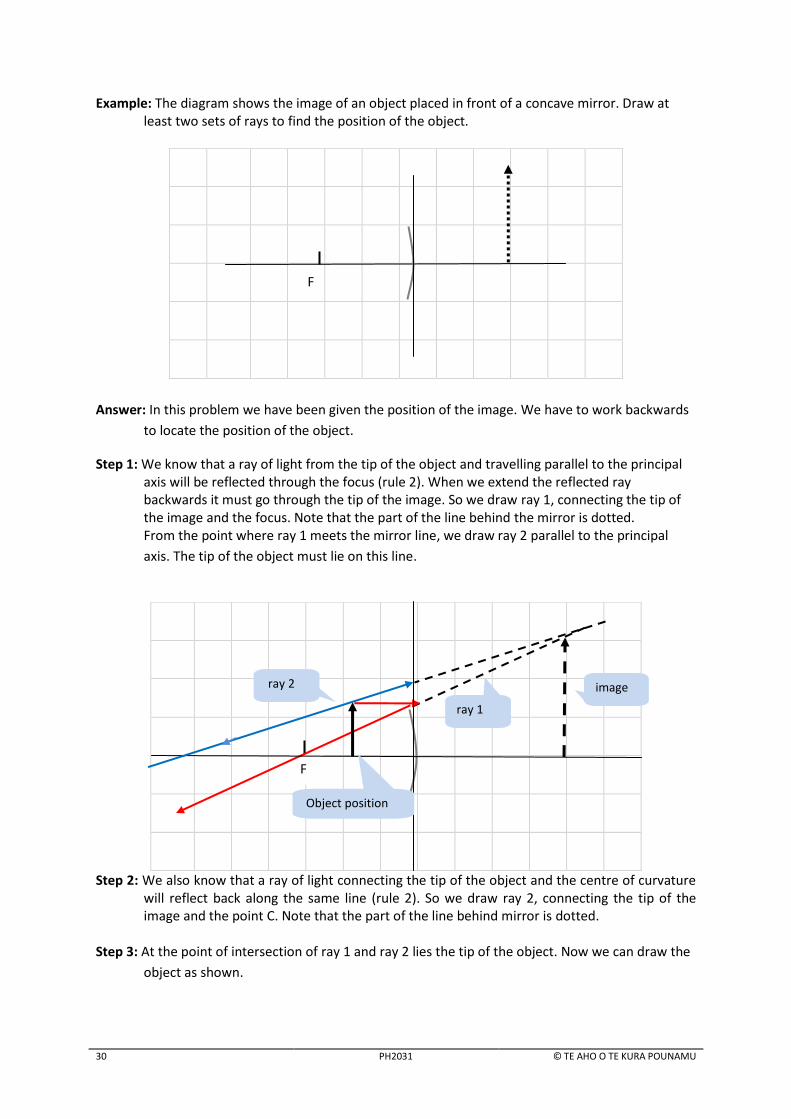
Example: The diagram shows the image of an object placed in front of a concave mirror. Draw at least two sets of rays to find the position of the object.
Answer: In this problem we have been given the position of the image. We have to work backwards
to locate the position of the object.
Step 1: We know that a ray of light from the tip of the object and travelling parallel to the principal axis will be reflected through the focus (rule 2). When we extend the reflected ray backwards it must go through the tip of the image. So we draw ray 1, connecting the tip of the image and the focus. Note that the part of the line behind the mirror is dotted. From the point where ray 1 meets the mirror line, we draw ray 2 parallel to the principal
axis. The tip of the object must lie on this line.
Step 2: We also know that a ray of light connecting the tip of the object and the centre of curvature will reflect back along the same line (rule 2). So we draw ray 2, connecting the tip of the image and the point C. Note that the part of the line behind mirror is dotted.
Step 3: At the point of intersection of ray 1 and ray 2 lies the tip of the object. Now we can draw the
object as shown.
F
F
image
ray 1
ray 2
Object position

USING CONCAVE MIRRORS
© TE AHO O TE KURA POUNAMU PH2031 31
CHECK YOUR UNDERSTANDING
1. A dentist uses a small concave mirror to look at a molar tooth. The focal length of the mirror is 5.0 cm.
a. Why do dentists use concave mirrors rather than plane mirror to examine teeth?
b. Complete the ray diagram to locate the image of a molar 0.50 cm high and 1.5 cm away
from the dentist’s mirror. Scale 1 square = 0.50 cm.
Each square represents 0.5 cm
c. What is the magnification of the image?
d. State the nature of the image.
2. Using same mirror of focal length 5.0 cm, the dentist sees an image of a small cavity. The image
appears to be 4.0 mm in size and 2.0 cm away from the mirror as shown in the diagram.
(Scale: vertical, 1 division = 1.0 mm; horizontal, 1 division = 1.0 cm).
a. Complete the diagram to locate the position of the tooth (object) in front of the mirror.
4F
F
F

32 PH2031 © TE AHO O TE KURA POUNAMU
b. Calculate the distance between the tooth and the mirror.
c. What is the size of the actual cavity?
Check your answers.
KEY POINTS
Scale diagrams are used to find the position, nature and the type of images formed by a
concave mirror.
The type of image depends on the position of the object, summarised in the diagram
below.
F C
Virtual and upright
No image Image same size
Diminished Magnified
Real and inverted
When the object is beyond C the image is real and diminished. This idea is used in telescopes.
When it is at C, the image is real, inverted and the same size.
If the object is between C and F, the image is always magnified and inverted.
When the object is at F, no image is formed because the rays travel parallel. This idea is used in solar cookers and car headlights.
When the object is placed within the focal length the image formed is always virtual, magnified and behind the mirror. This idea is used in a dentist’s mirror.
CONCAVE MIRROR CALCULATIONS
© TE AHO O TE KURA POUNAMU PH2031 33
5 CONCAVE MIRROR CALCULATIONS
LEARNING INTENTIONS In this lesson you will learn to:
use the equation
to find the position of an image for an object placed in front of
a concave mirror.
use
and
to find the magnification and the size of the image.
INTRODUCTION In the previous lesson you learnt how to locate the images formed by a concave mirror using a ray diagram. In this lesson you will learn how to calculate the position of an image produced by a concave mirror using the mirror equation.
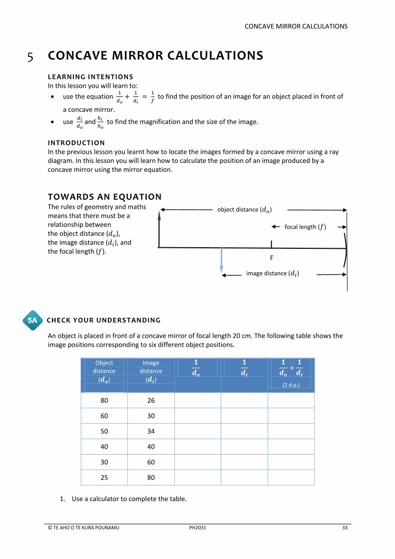
TOWARDS AN EQUATION The rules of geometry and maths means that there must be a relationship between the object distance ( ), the image distance ( ), and the focal length ( ).
CHECK YOUR UNDERSTANDING
An object is placed in front of a concave mirror of focal length 20 cm. The following table shows the image positions corresponding to six different object positions.
Object
distance
( )
Image distance
( )
(2 d.p.)
80 26
60 30
50 34
40 40
30 60
25 80
1. Use a calculator to complete the table.
5A
F
image distance ( )
focal length ( )
object distance ( )

34 PH2031 © TE AHO O TE KURA POUNAMU
CALCULATOR HELP Scientific calculators have a reciprocal function marked as
To find the value of the inverse of 80, type 80 and press the inverse button. The display will show 0.125.
2. Find the average value of the quantities in the last row.
The average value is
3. The focal length of the mirror is 20 cm. Calculate the inverse of the focal length
4. How does the average value of
compare with the
value?
Check your answers.
USING THE EQUATION
In the previous activity, within the limits of experimental error, we can conclude that the sum of
is equal to the value of
.
We can use this information to construct a mathematical formula relating , and for a concave
mirror. The formula is:
This formula can be used to find the position of an image produced by a concave mirror.
Example 1: A concave mirror forms a real image at 25 cm from the mirror surface along the principal
axis. If the object is at a 10.0 cm distance, what is the mirror’s focal length?
Answer
Step 1: Collect the given data. = 10 cm, = 25 cm.
Step 2: The quantity to be calculated is the focal length, = ?
Step 3: Put the data into the formula.

CONCAVE MIRROR CALCULATIONS
© TE AHO O TE KURA POUNAMU PH2031 35
Step 4: Use a calculator to find the value of .
CALCULATOR HELP On your calculator, type in
10
25
The display will give you an answer of 0.14. This is the value of . So is the inverse of 0.14.
HOW DO WE ROUND THIS ANSWER? Note that your final answer in this case has more significant figures, while none of your starting numbers did. Your final answer cannot be any more accurate than the least accurate data. In the given data 10.0 cm has 3 significant figures and 25 has 2 significant figures. The least accurate data is 25, which has 2 significant figures. Therefore your final answer should be rounded to 2 significant figures. So the rounded value of the focal length is 7.1 cm.
Example 2: If the size of the object in example 1 is 6.0 cm, what is the size of the image?
Answer: Using the magnification formula we can calculate the size of the image. The formula for magnification is
Example 3: A concave mirror with a focal length of 10 cm creates a real image 30 cm away on its
principal axis. Calculate the distance of the object from the mirror.
Answer
Step 1: Collect the given data. = 10 cm, = 30 cm.
Step 2: The quantity to be calculated is the object distance, = ?
Step 3: Put the data into the formula.

36 PH2031 © TE AHO O TE KURA POUNAMU
Step 4: Rearrange the equation to find :
Step 5: Use a calculator to find the value of .
CALCULATOR HELP On your calculator, type in
10
30
The display will give you an answer of 0.0666. This is the value of
.
VIRTUAL IMAGES When the object is placed between the focus and the mirror, the image formed is virtual. Because
the virtual image is behind the mirror, the image distance is also virtual. This is because no light rays
travel behind the mirror to form the image. Our eyes focus the reflected rays to a point where we
see an image.
To differentiate virtual quantities from real ones, virtual quantities are negative.
When a virtual image is formed behind a mirror the quantity is virtual. We indicate this by
assigning a minus sign to the image distance .
Example 4: The bathroom mirror on page 29 is being used to produce a virtual magnified image of
the flowers. The concave mirror has a focal length of 2 cm and the object distance is 1 cm.
Calculate the precise position of the image and, from this, the magnification of the image.
Step 1: Collect the given data. = 1.0 cm, = 2.0 cm. we need
Step 2: Calculate .
Real distances are positive ( )
Virtual distances are negative ( )

CONCAVE MIRROR CALCULATIONS
© TE AHO O TE KURA POUNAMU PH2031 37
Because works is a negative value we know that the image is virtual. Check page 29 to see a ray diagram showing this.
Step 3: Calculate the magnification In the ray diagram (see page 29 ) you can see that the virtual image is clearly larger than the object, so the magnification must be more than one. (If the image was smaller the magnification would be less than one). We don’t need a negative number to describe magnification, we just use the distances, ignoring the sign. This can be written mathematically as:
So, for this example:
Check page 29 – you can see that the image is indeed twice the height of the object.
Example 5: A dentist wants a small mirror that, when placed 2.2 cm from a tooth, will produce an
upright image with a magnification of 4.5. Calculate the radius of curvature of the mirror.
Answer
Step 1: Collect the given data. = 2.2 cm, = 4.5 cm. To get the radius of curvature we
need to calculate , and for this we need
Step 2: Calculate .
The formula for magnification is
since the image is virtual is negative.
Step 3: Calculate .
Re write the equation as:
CALCULATOR HELP On your calculator, type in
2.2
9.9
The display will give you an answer of 0.3535. This is the value of .
Step 4: The radius of curvature of the mirror is double the focal length.

38 PH2031 © TE AHO O TE KURA POUNAMU
CHECK YOUR UNDERSTANDING
1. A concave mirror has a radius of curvature of 20 cm. An object is placed 30 cm in front of the mirror. a. What is the focal length of the mirror?
b. Calculate the position of the image.
c. What is the magnification of the image?
d. Calculate the size of the image if the object is 5.0 cm tall.
2. Kim holds a concave mirror 15.0 cm from an insect. The focal length of the mirror is 18 cm.
a. Show that the distance of the image of the insect from the mirror is 90 cm.
b. Calculate the magnification of the image.
c. If the insect is 3.0 mm high, calculate the size of the image.
5B

CONCAVE MIRROR CALCULATIONS
© TE AHO O TE KURA POUNAMU PH2031 39
3. Torches use concave mirrors to maximise the brightness of the beam of light they emit. The focal length of a concave mirror in a torch light is 3.0 cm.
a. Calculate the position of the centre of curvature of the mirror.
b. On the diagram, write the letter B to show where the light bulb should be placed to provide
a parallel beam of light.
c. Explain why the position for the light bulb you chose in (b) will provide a parallel beam of light.
4. Jane uses a concave mirror to enlarge a match head. Jane places the match head at a distance of
4.1 cm from the mirror. The focal length of the mirror is 4.2 cm. a. Calculate the distance of the image from the mirror.
b. Calculate the magnification of the image.
reflecting side
Principal axis
focal length = 3cm

40 PH2031 © TE AHO O TE KURA POUNAMU
c. Explain why the magnification has no units.
d. Using your answer to (b) as an example, explain the meaning of the term ‘magnification’.
e. Calculate how far the match needs to be placed from the mirror to obtain a real image
half the size of the match.
Check your answers.
KEY POINTS
The mirror equation expresses the quantitative relationship between the object distance
( ), the image distance ( ), and the focal length ( ).
If the image is virtual, the image distance is negative.
Negative values are ignored when calculating magnification.

CONVEX MIRRORS
© TE AHO O TE KURA POUNAMU PH2031 41
6 CONVEX MIRRORS
LEARNING INTENTIONS In this lesson you will learn to:
use the terms: centre of curvature, radius of curvature, and principal focus as applied in
relation to a convex mirror
describe the characteristics of the image formed by a convex mirror.
INTRODUCTION In the previous lessons you looked at the images formed by a concave mirror. You also used a ray
diagram or the mirror formula to predict the position and magnification of the image formed by a
concave mirror. In this lesson you will explore the characteristics of the image formed by a convex
mirror.
WHAT IS A CONVEX MIRROR?
A convex mirror is a mirror that curves
outward in the middle – like the back of
a spoon. Like a concave mirror, a convex
mirror is a cut away portion of a glass
sphere. It is then silvered on the inside
side of the sphere to form a reflecting
surface.
The centre of curvature and the principal focus are behind the mirror. No rays that fall on the mirror
pass through the focus or centre of curvature. Both the focus and the centre of curvature are virtual
so the focal length is negative.
When a set of parallel rays is shone
towards a convex mirror they reflect and
diverge (spread out) from the mirror. A
person looking at the reflected rays will
see them as though they are coming from
the principal focus F, behind the mirror
and diverging out. For this reason the
convex mirror is also called a diverging
mirror.
Notice that we draw broken lines behind the mirror to show that, in reality, no light rays travel
behind the mirror – they appear to come from the focal point. The focal length ( ) is half the length
of the radius of curvature (as in the case of a concave mirror) and it is negative.
F C
Principal axis
Slivered surface
Reflecting surface
C F
C

42 PH2031 © TE AHO O TE KURA POUNAMU
HANDS-ON ACTIVITY: SHINY SPOON
What you need:
a large shiny spoon or similar
soft tissue or cloth. What you do:
1. Polish the back of the spoon with the tissue. 2. Hold the spoon about 10 cm from your eyes with the
back (convex side) facing you. 3. Slowly move the spoon away from you. 4. Describe what you see.
5. Is your image virtual or real? Explain your answer.
6. In which position of the spoon do you get the greatest view of field (i.e. larger viewing area)?
7. Now hold the spoon closer to your face with the front (concave side) facing you. Slowly
move the spoon away from you. Describe what you see. Explain your answer.
Check your answers.
6A

CONVEX MIRRORS
© TE AHO O TE KURA POUNAMU PH2031 43
RULES FOR RAY DIAGRAMS A ray diagram is a useful tool that is used to determine the location, size, orientation, and type of image formed by a mirror. The following five rules are formulated by observing how a ray of light interacts with a convex mirror
Rule 1 An incident ray of light that travels along the principal axis is reflected back on the same path. (This is the law of reflection.)
Rule 2 An incident ray that travels parallel to the principal axis is reflected as though it came from the principal focus F.
Rule 3 An incident ray that travels towards the principal focus F is reflected in such a way that it travels parallel to the principal axis. (This is the reverse of Rule 2, which shows that the path of the light is reversible.)
Rule 4 An incident ray that strikes the centre of the mirror at a certain angle to the principal axis is reflected from the mirror at the same angle.
Rule 5 An incident ray that travels towards the centre of curvature is reflected back along its own path. (This is the law of reflection.)
CONSTRUCTION OF RAY DIAGRAMS TO LOCATE THE IMAGE
We can use the rules described in the previous section to construct ray diagrams to locate the image
formed when an object is placed in front of a convex mirror. You must use Rule 1 for all ray diagrams
and may choose any other two rules to complete the diagram. The following example shows how to
construct a ray diagram step by step.

44 PH2031 © TE AHO O TE KURA POUNAMU
Example 1: An object 2.0 cm high is placed 5.0 cm in front of a convex mirror of focal length 3.0 cm. Construct a scaled ray diagram to find the nature, size and position of the image produced by the mirror.
Step 1 We use standard conventions to construct a ray diagram. The basic set-up for all convex mirror diagrams is the same as described below.
First we draw a vertical line called the mirror line which represents the reflecting surface; that is, the front of the mirror. Although the mirror surface is curved, the mirror line is a straight vertical line. A ray diagram tends to use a large mirror line to represent the mirror so that there is very little loss of accuracy.
The next step is to locate the principal focus F for the mirror, and its centre of curvature C, on the principal axis to scale. In this case we use 1 cm = 1 square. So the focus F is 3 squares from the mirror, and the centre of curvature C, is 6 squares from the mirror.
Step 2 Now we draw an arrow for the object in front of the mirror line. The object is placed 5.0 cm (5 squares) from the centre of the mirror and it is 2.0 cm (2 squares) high.
C F
Mirror line
C F

CONVEX MIRRORS
© TE AHO O TE KURA POUNAMU PH2031 45
Step 3 In this step we are apply the rules. Rules 1, 2 and 5 can be applied to all ray diagrams relating to a convex mirror.
Rule 1 - An incident ray of light that travels along the principal axis is reflected back along its own path. We show this by adding two arrows in the opposite directions on the principal axis. Rule 2 - An incident ray that travels parallel to the principal axis is reflected as though it came from the principal focus F. Draw an incident ray from the tip of the object and parallel to the principal axis. This ray is reflected from the mirror line as if it is coming from the principal focus, F. Rule 5 - An incident ray that travels through the centre of curvature is reflected back along the same path. Draw a ray from the tip of the object to the centre of curvature. It is reflected back along its own path which is shown by the arrow. Remember, all the rays behind the mirror use broken lines.
Step 4 In this step we locate the image. The image is formed where the two imaginary rays meet behind the mirror. This is where the tip of the image is and its tail is on the principal axis. The image is virtual, so we use broken lines to draw the image.
DESCRIBING THE IMAGE The image is fully described by its:
Nature – Because the reflected rays do not actually meet to produce the image, it is a virtual
image. We show this by drawing the image in broken lines.
Position – The scale is 1square = 1 cm. The image is about 1.8 squares from the mirror,so the
image is 1.8 cm from the mirror.
Orientation – The image is upright.
Size – In this case the image is diminished because it is smaller than the object.
Magnification – The distance from the object to the mirror is the object distance do, and the
distance from the mirror line to the image is the image distance .
The formula for magnification is
object
Rule 5
Rule 2
Rule 1
image
C F

46 PH2031 © TE AHO O TE KURA POUNAMU
Irrespective of the position of the object, the image formed by a convex mirror is always:
behind the mirror, between the mirror and the principal focus
upright
diminished.
Example 2: The diagram below shows the position of the image produced by a convex mirror when an object is placed in front of it. Complete a ray diagram and find (i) the position and (ii) the size of the object. (Scale 1 Sq = 3 cm.)
Answer 1. First we will use rule 2. We line up the top of the image and the principal focus and draw a
line. Then we locate the point of intersection of this line with the mirror line. From this
point we draw a line parallel to the principal axis. The arrow end of the object must be
somewhere on this line.
2. To find the exact position of the object we now use rule 5. Line up the top of the image and
point C and draw a line.
3. Next we locate the point of intersection of this line and the line parallel to the principal axis.
The arrow end of the object must be at this point of intersection.
4. Now draw the object. The object is located where the two rays meet. Draw an arrow for the
object.
Remember, all lines behind the mirror are broken to show that rays do not travel behind the mirror.
Object
C F
Image
C F

CONVEX MIRRORS
© TE AHO O TE KURA POUNAMU PH2031 47
i. Each square is 3 cm and the object is about 6.4 squares from the mirror. The object distance is 6.3 x 3 = 18.9 cm from the mirror.
ii. The object is 3 times the size of the image (3 squares up). The object size is 3 x 3 = 9.0 cm.
CHECK YOUR UNDERSTANDING
1. In the diagram below an object is placed in front of a convex mirror.
Each square is 4.0 cm
a. On the diagram mark the position of the centre of curvature of the mirror.
b. Calculate the focal length of the mirror.
c. Explain why the focal length is virtual.
d. Complete the diagram to locate the position of the image.
e. Calculate the magnification and the size of the image.
6B
F

48 PH2031 © TE AHO O TE KURA POUNAMU
2. a. Complete the diagram below to find the position of the object. (Scale: vertical, 1
division = 1.0 mm; horizontal, 1 division = 1.0 cm.)
b. State the object distance from the mirror.
c. Calculate the magnification of the image.
Check your answers.
KEY POINTS
A convex mirror is shaped like the back of a spoon. The inner surface of the spherical surface is silvered so that the outer spherical surface reflects light.
The focal length of the mirror is always virtual because it is behind the mirror.
The image formed by a convex mirror is always virtual, diminished and behind the mirror.
C F

CONVEX MIRROR CALCULATIONS
© TE AHO O TE KURA POUNAMU PH2031 49
7 CONVEX MIRROR CALCULATIONS
LEARNING INTENTIONS In this lesson you will learn to:
calculate the position of the image of an object placed in front of a convex mirror.
find the magnification and the size of the image formed by convex mirror.
INTRODUCTION In the previous lesson you learnt how to use ray diagrams to locate the images formed by a convex
mirror. In this lesson we are going to calculate the position of an image produced by a convex mirror.
CONVEX MIRROR FORMULA The following equation expresses the relationship between the object distance ( ), the image
distance ( ), and the focal length ( ).
Note that for convex mirrors:
the focal length of a convex mirror is virtual; so it is negative
the object distance ( ) is real, so it is positive.
the image formed by a convex mirror is always virtual, so the image distance ( is
negative. The formula that relates these quantities is the same, but you need to make sure that all virtual
quantities have negative distances:
Example 1: A convex mirror forms an image 6.5 cm behind the mirror. If the object is 15.0 cm in
front of the mirror, what is the focal length of the mirror?
Answer
Step 1: Collect the given data. , .
Step 2: Identify the quantity required. focal length, =?
Step 3: Put the data into the formula.
F
Image distance ( )
Object Image
Object distance ( )
Focal length,

50 PH2031 © TE AHO O TE KURA POUNAMU
Step 4: Use a calculator to find the value of .
CALCULATOR HELP On your calculator, type in
15
6.5
The display will give you an answer of 0.087. This is the value of
.
The principal focus is virtual (the negative sign tells us this) and it is 11.5 cm behind the mirror.
Example 2: If the size of the object in example 1 is 3.6 cm what is the size of the image?
Answer
Magnification ( ) compares the distances and sizes of the images, so you should ignore any
negative signs.
Example 3: A convex mirror with a focal length of 10 cm creates a virtual image 6.5 cm away from
the mirror on its principal axis. Calculate the distance of the object from the mirror.
Answer
Step 1: Collect the given data. – , -
Step 2: The quantity to be calculated is the object distance from the mirror, =?
Step 3: Put the data into the formula.
Step 4: Rearrange the equation as:
Step 5: Use a calculator to find the value of .
CALCULATOR HELP On your calculator, type in
6.5
10
The display will give you an answer of 0.0538. This is the value of
.

CONVEX MIRROR CALCULATIONS
© TE AHO O TE KURA POUNAMU PH2031 51
CHECK YOUR UNDERSTANDING
1. A 4.0 cm tall light bulb is placed a distance of 35.5 cm from a convex mirror that has a focal
length of 12.2 cm. Determine the image distance and the image size.
2. Determine the focal length of a convex mirror that produces an image that is 16.0 cm behind the
mirror when the object is 28.5 cm from the mirror.
3. A convex mirror is placed on the ceiling at the intersection of two aisles in a supermarket. A child
stands in front of the mirror and 195 cm away from it. The mirror forms an image of the child that appears 12.8 cm behind the mirror.
a. Calculate the focal length of the mirror.
b. What is the magnification of the child’s image?
7A
52 PH2031 © TE AHO O TE KURA POUNAMU
c. Is the image real or virtual? Explain your answer,
Check your answers.
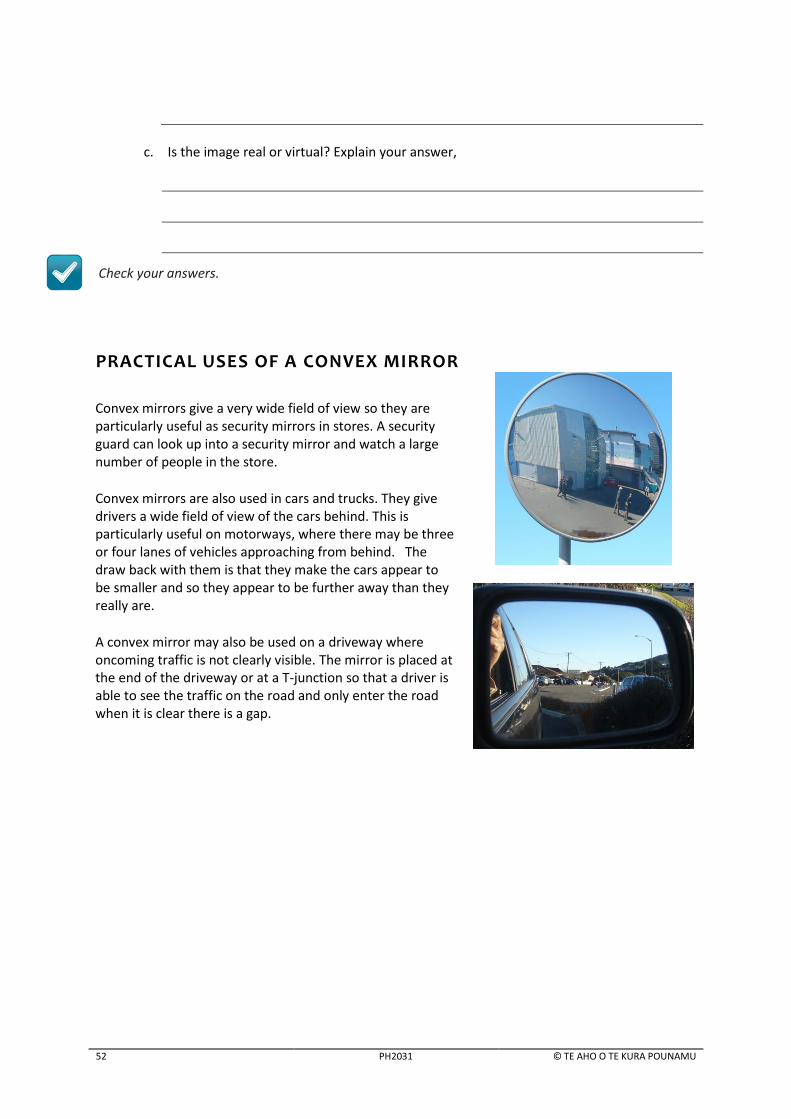
PRACTICAL USES OF A CONVEX MIRROR
Convex mirrors give a very wide field of view so they are particularly useful as security mirrors in stores. A security guard can look up into a security mirror and watch a large number of people in the store.
Convex mirrors are also used in cars and trucks. They give drivers a wide field of view of the cars behind. This is particularly useful on motorways, where there may be three or four lanes of vehicles approaching from behind. The draw back with them is that they make the cars appear to be smaller and so they appear to be further away than they really are.
A convex mirror may also be used on a driveway where oncoming traffic is not clearly visible. The mirror is placed at the end of the driveway or at a T-junction so that a driver is able to see the traffic on the road and only enter the road when it is clear there is a gap.
CONVEX MIRROR CALCULATIONS
© TE AHO O TE KURA POUNAMU PH2031 53
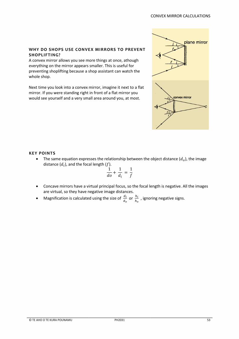
WHY DO SHOPS USE CONVEX MIRRORS TO PREVENT SHOPLIFTING? A convex mirror allows you see more things at once, athough everything on the mirror appears smaller. This is useful for preventing shoplifting because a shop assistant can watch the whole shop. Next time you look into a convex mirror, imagine it next to a flat mirror. If you were standing right in front of a flat mirror you would see yourself and a very small area around you, at most.
KEY POINTS
The same equation expresses the relationship between the object distance ( ), the image distance ( ), and the focal length ( ).
Concave mirrors have a virtual principal focus, so the focal length is negative. All the images are virtual, so they have negative image distances.
Magnification is calculated using the size of
or
, ignoring negative signs.

54 PH2031 © TE AHO O TE KURA POUNAMU
8 CALCULATIONS AND SIGNIFICANT FIGURES
LEARNING INTENTIONS In this lesson you will learn to:
identify the number of significant figures in a given set of data
apply rules that will help you to round the final answer to the correct number of significant figures to the accepted standard
use Newton’s formula to calculate the position of an image produced by a curved mirror.
SIGNIFICANT FIGURES Significant figures are very important in physics calculations. They represent the accuracy of the data
and hence the final answer. Each given measurement has a certain number of significant figures.
Calculations done on these measurements must follow the rules for significant figures.
HOW TO FIND THE NUMBER OF SIGNIFICANT FIGURES IN A NUMBER The rules for determining the number of significant figures in a given measurement are as follows.
Digits from 1–9 are always significant. For example, 467 km has 3 significant figures.
Zeros between two other significant digits are always significant. For example, 407 km has 3 significant figures and 0.5007 has 4 significant figures
Zeros used solely for marking the decimal point (placeholders) are not significant. For example, 0.0004 km has 1 significant figure. This is because the zeroes on the left of the 4 are only decimal holders, so they are not significant.
One or more additional zeros to the right of both the decimal place and another significant digit are significant. For example, 0.000400 km has 3 significant figures.
There are some exceptions. For example, 100 is considered to be 1 significant figure if zeros are considered as place holders, and as 3 significant figures if they are not. On the other hand, to avoid the ambiguity, we can write 100 as 1 x 10² which has 1 significant figure.
Recognising significant figures is important in the examination because you need to write your final
answers to the correct number of significant figures. It will become much easier over time, as you
continue to practice the rules. When you complete the calculations in the teacher-marked
assignments you should always follow the significant figure rules.
CHECK YOUR UNDERSTANDING
Complete the following table by writing the number of significant figures in the second column
and giving a brief reason why the figures are significant. The first row is done for you.
8A

CALCULATIONS AND SIGNIFICANT FIGURES
© TE AHO O TE KURA POUNAMU PH2031 55
Data Number of significant
figures Reason
6893 m 4 All non-zero digits are always significant.
9007 kg
5.00 cm
0.007 mm
0.005001 g
3.00 x 10⁵ m
CALCULATIONS AND SIGNIFICANT FIGURES
Each recorded value contains a certain number of significant figures. When we do calculations our
answers cannot be more accurate than the measurements that they are based on. We follow certain
rules whenever we do calculations using the given data. They are given below.
HOW TO FIND THE NUMBER OF SIGNIFICANT FIGURES IN A CALCULATED VALU E 1. Adding and subtracting
When adding or subtracting the given data, the final answer can only show as many decimal places as the measurement that has the fewest decimal places. Example:
Look at the original data to see the number of decimal places shown in each value. 3.4 has the fewest decimal places. We must round our answer, 32.36, to one decimal place. Therefore the final answer is 32.4 cm
. 2. Multiplying and dividing
When multiplying or dividing, round the calculated answer until you have the same number of significant figures as the measurement with the fewest significant figures. Example:
Look at the original data to check the number of significant figures in each value: 22.37 has 4 significant figures. 3.10 has 3 significant figures – the fewest 85.75 has 4 significant figures.
Our answer can only show 3 significant figures because that is the fewest significant figures in the given data. 5946.50525 shows 9 significant figures, but we must round to show only 3 significant figures. Our final answer becomes 5950 cm3. In this case zero is not significant. You can avoid ambiguity if you write your answer as 5.95 x 102 cm3 (or 5950 cm3 3 s.f.)

56 PH2031 © TE AHO O TE KURA POUNAMU
CHECK YOUR UNDERSTANDING
Complete the table below by calculating the given data and rounding the answer to the correct number of significant figures.
Data for calculation Calculated value Rounded answer
NEWTON’S FORMULA This section is optional. It deals with an alternate formula which can be used to calculate the
position of the image formed by a curved mirror. The end-of-year NCEA examination paper will give
you both formulae.
The formula you have learnt in this booklet is known as the Gaussian formula. It is the most
commonly used formula, but you need to operate reciprocal calculations well to use it. If you do not
feel confident in operating reciprocals then consider using Newton’s formula. Any one of these
equations may be used to solve problems relating to curved mirrors but the two systems should not
be mixed up.
The well-known physicist Newton derived this formula from the Gaussian formula.
is the focal length is the distance between the object and the principal focus. is the distance between the image and the principal focus.
8B

CALCULATIONS AND SIGNIFICANT FIGURES
© TE AHO O TE KURA POUNAMU PH2031 57
In Newton’s formula the measurements are made from the principal focus,
From the diagram it is clear that:
and
You can calculate the magnification of the image by using the formula:
Example: An object 3 cm high is placed 24 cm in front of a concave mirror of 8 cm focal length. a. Find the image distance. b. Calculate the image size.
Answer a. Data given: = 24 cm, = 8 cm
b.
F
image distance
focal length
object distance
58 PH2031 © TE AHO O TE KURA POUNAMU
CHECK YOUR UNDERSTANDING
1. An object 2 cm high is placed 20 cm in front of a concave mirror of +12 cm focal length. Use Newton’s formula to find the nature, size and position of the image formed.
2. An object 2 cm high is placed 30 cm in front of a concave mirror of 10 cm focal length. Use
Newton’s formula to find the nature, size and position of the image formed.
Check your answers.
KEY POINTS
Significant figures are very important in physics calculations. They represent the accuracy of the data and hence the final answer.
Rounding the final answer of a mathematical calculation to the correct number of significant figures is important to represent the accuracy of the data.
8C

TEACHER-MARKED ASSIGNMENT
© TE AHO O TE KURA POUNAMU PH2031 59
9 TEACHER-MARKED ASSIGNMENT
LEARNING INTENTIONS In this lesson you will learn to:
review your progress over this topic and practise exam-type questions. INT RODUC TION
In this lesson you will take a quick look back at all the lessons you have completed in this topic. Think about what you have learned. When you are ready, try the teacher-marked assignment PH2031A. If you did not receive this with your booklet, contact your teacher. When you have finished, complete the self-assessment section at the end of this booklet. Send the booklet and the teacher-marked assignment to your teacher. Make sure that you have written your name and ID number on the back cover of your booklet and the teacher-marked assignment. You can also use a label if you have one at hand. By post: Put the booklet and teacher-marked assignment in the plastic envelope provided. Make sure that the address card shows the Te Aho o Te Kura Pounamu (The Correspondence School) address. Seal the envelope with tape before you post it. By email: Scan the pages including the cover sheet and email to your teacher. The standard format for Te Kura teacher email addresses is: [email protected] If you aren’t sure who your teacher is, call 0800 65 99 88.
Before you finish this topic you should have agreed your next steps with your teacher. If you do not have your next set of study materials, contact your teacher immediately. If you are not sure what to do next, ask your teacher for advice.

60 PH2031 © TE AHO O TE KURA POUNAMU
10 ANSWER GUIDE
QUICK QUIZ
1. 1.2 m
2. 1.6 m
3.
a. The distance of the image from the mirror now doubles. It is 2 x 1.2 = 2.4 m.
b. The magnification of the image is the same because the image size does not change.
4. The image is virtual because the rays from the clown bounce back from the mirror – they do not
actually come from the image.
5.
QUICK QUIZ
1. Angle of incidence is 90o – 30o = 60o . Since angle of incidence = angle of reflection, the answer is
60o
2.
a. 60o + 60o = 120 o
b. 90o – 60o = 30o °
HANDS-ON ACTIVITY: FINDING FOCAL LENGTH
6. Depending on where you judge the sharp image is, the answer could be anything from 18 to 22.
CHECK YOUR UNDERSTANDING
1 a & b
c. The focal length becomes smaller because the radius of curvature is less if the mirror is curved more.
2.
a. Concave b. At the focal point or focus of the dish
because all the signals after reflection from the surface of the dish will travel towards the focus.
c. The strength of the signal increases because more of them would be reflected towards the focus.
F C
2B
2A
1C
1B

ANSWER GUIDE
© TE AHO O TE KURA POUNAMU PH2031 61
HANDS-ON ACTIVITY: IMAGES IN CONCAVE MIRRORS
7.
Distance of the light from the mirror (cm).
Distance of the image from the mirror (cm).
Image size (larger / smaller / same size)
Nature of the image:
(upright / upside down)
60 smaller upside down
50 smaller upside down
40 almost same size upside down
30 larger upside down
8. As the object gets closer to the mirror, the image becomes bigger. 9. As the object distance gets smaller, the image distance becomes larger.
CHECK YOUR UNDERSTANDING
1.
a.
b. Nature: Real; Size: Diminished; Position: Between 7 and 7.3 cm from the mirror is
acceptable.
c. The formula for magnification is
7
2. a, b &c
3B
2C
C F
F C

62 PH2031 © TE AHO O TE KURA POUNAMU
d. Nature: Real; Size: Same; Position: 12 cm from the mirror.
e.
CHECK YOUR UNDERSTANDING
1. a. Your diagram should be similar to this but in scale. This diagram is not exactly scaled because
the printing process causes some distortion.
b. The image is real, inverted and 30 cm in front of the mirror (27 to 35 cm is acceptable).
c. The image is 3 cm high (2.7 to 3.3 cm is acceptable).
(1.3 to 1.7 is acceptable)
2. a. Your diagram should be similar to this:
b. The image is real, inverted and is 15 cm in front of the mirror (12 to 18 cm is acceptable).
c. The image is 1 cm high (1.7 to 2.3 cm is acceptable) so
(0.3 to 0.7 is acceptable)
HANDS-ON ACTIVITY: FINDING THE RADIUS OF CURVATURE
6. This answer depends on your judgment of where the sharp image is, the answer could be
anything between18 and 22 cm.
7. Focal length is half the value of your answer to (7); between 9 and 11 cm.
4B
4A

ANSWER GUIDE
© TE AHO O TE KURA POUNAMU PH2031 63
CHECK YOUR UNDERSTANDING
1.
2. b. Nature: Real; Size: Same; Position: 12 cm from the mirror.
c.
HANDS-ON ACTIVITY: BIG EYE
2. Magnified, virtual, upright.
BATHROOM MIRROR
B is the concave side – you can tell because the image is slightly bigger.
CHECK YOUR UNDERSTANDING
1a. A concave mirror produces a magnified virtual image, whereas a plane produces an image that is the same size as the object. b.
c. The answer can be worked out from the distance or the heights:
and
d. Virtual, upright, enlarged
4F
4E
4D
C F
F
4C

64 PH2031 © TE AHO O TE KURA POUNAMU
2a.
b. 1.2–1.5 cm acceptable. c. 3 mm
CHECK YOUR UNDERSTANDING
Object distance 80 60 50 40 30 25
Image distance 26 30 34 40 60 80
Inverse of object distance 0.0125 0.0167 0.02 0.025 0.033 0.04
Inverse of image distance 0.038 0.033 0.029 0.0250 0.0167 0.0125
Sum 0.050 0.050 0.049 0.050 0.050 0.053
1.
Object distance
( )
Image distance
( )
(2 d.p.)
80 26 0.0125 0.038 0.05
60 30 0.0167 0.033 0.05
50 34 0.02 0.029 0.049
40 40 0.025 0.025 0.05
30 60 0.033 0.0167 0.05
25 80 0.04 0.0125 0.053
2. Average value = 0.050
3. 0.050
4. They are the same.
CHECK YOUR UNDERSTANDING
1. a. Because the radius of curvature is 20 cm (which is the distance from the mirror to the
centre), and the focal point is half of it b.
5B
5A
F

ANSWER GUIDE
© TE AHO O TE KURA POUNAMU PH2031 65
c.
d.
2.
a.
b.
c.
3.
a.
b.
c. All the light rays from the focal point that strike the mirror will be reflected parallel to principal axis.
4.
a.
b.
c. Magnification is the ratio of two distances and since the distances are measured in the same units they cancel out each other.
d. Magnification is how big or small the images is compared to the object. In this case the image is 0.41 times smaller than the object.
reflecting side
Principal axis
focal length = 3cm
C B

66 PH2031 © TE AHO O TE KURA POUNAMU
e.
Substituting for in the equation:
Multiplying both sides by 0.5:
HANDS-ON ACTIVITY: SHINY SPOON
4. You see the image of your face to begin with. As you move the spoon away, the size of the image decreases but the field view increases (i.e. you see more of you in the spoon).
5. The image is virtual because no light rays pass behind the spoon to form the image. 6. The field of view is the largest when the spoon is furthest from you. 7. No image is formed, because the image formed is real, in front of the spoon, and needs a screen
to track it.
CHECK YOUR UNDERSTANDING
1. a. See the diagram
Each square is 4.0 cm
b.
c.
Because the focal point is behind the mirror no light passes through it. It is therefore virtual and the focal length is also virtual.
d. See above. e.
(Any answer closer to 0.50 is acceptable)
6B
6A
C F
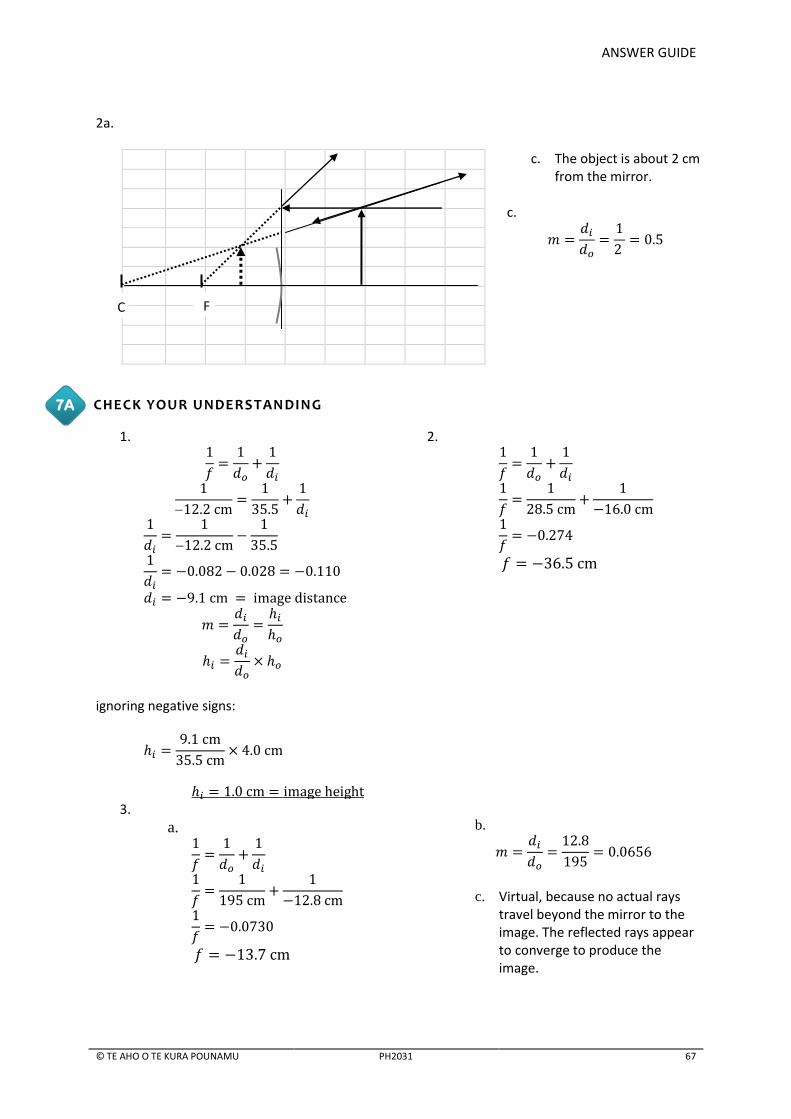
ANSWER GUIDE
© TE AHO O TE KURA POUNAMU PH2031 67
2a.
c. The object is about 2 cm from the mirror.
c.
CHECK YOUR UNDERSTANDING
1.
2.
ignoring negative signs:
3.
a.
b.
c. Virtual, because no actual rays
travel beyond the mirror to the image. The reflected rays appear to converge to produce the image.
7A
C F

68 PH2031 © TE AHO O TE KURA POUNAMU
CHECK YOUR UNDERSTANDING
Data Number of significant
figures Reason
6893 m 4 All non-zero digits are always significant
9007 kg 4 All non-zero digits are always significant
5.00 cm 4 Zeros between 2 significant digits are significant
0.007 mm 3 Additional zeros to the right of decimal and significant digits are significant
0.005001 g 1 Placeholders are not significant
3.00 x 10⁵ m 4 Zeros between 2 significant digits are significant
CHECK YOUR UNDERSTANDING
Data for calculation Calculated value Rounded answer
52.64 53
191.046 191
17.61997… 18
1.3924…… 1.4*
25.1052… 25
*This has a mix of subtraction and division, with different rules, so you must do them separately. 23.5 – 21.3 = 2.2 (with one decimal place) and then dividing 2.2 by 1.58, the answer is 1.4 with 2 significant figures. The limiting factor is 2.2, with 2 significant figures, so the final answer should have 2 significant figures.
CHECK YOUR UNDERSTANDING
1.
2.
so the image is magnified. The image distance is positive, so the image is real and inverted.
so the image is diminished. The image distance is positive, so the image is real and inverted.
8C
8B
8A

ACKNOWLEDGEMENTS
© TE AHO O TE KURA POUNAMU PH2031 69
ACKNOWLEDGEMENTS
Every effort has been made to acknowledge and contact copyright holders. Te Aho o Te Kura Pounamu apologises for any omissions and welcomes more accurate information.
Extracts: PhET Interactive Simulations,University of Colorado,http://phet.colorado.edu. Extract only.
All diagrams created by Joseph Fernandez, Wellington, New Zealand. Used by permission.
Photos: Student at desk; Girl at mirror; How does image form experiment; Satellite dish; Images in concave mirrors
experiment; Big eye experiment; Woman looking at shiny spoon; Rear vision mirrors x 2, all © Joseph Fernandez,
Wellington, New Zealand. Used by permission
Photo: Reflective sculpture; Roses & reflection, Two spoons all © Kerry Parker, Wellington, New Zealand. Used by
permission.
Diagram: Woman at mirror by Kerry Parker, Wellington, New Zealand. Used by permission
Clip art: World map; Woman at mirror © Microsoft Corporation. Used within the EULA.
Photos: Solar Cooker, by http://www.atlascuisinesolaire.com, retrieved from
http://commons.wikimedia.org/wiki/File:ALSOL.jpg; Detail of military dentists in Guatemala, by U.S. Air Force, photo by
Master Sgt. Ruby Zarzyczny, retrieved from http://commons.wikimedia.org/wiki/File:Military_dentists_in_Guatemala.jpg;
Hubble mirror polishing, by NASA Marshall Space Flight Cente,r retrieved from
http://commons.wikimedia.org/wiki/File:Hubble_mirror_polishing.jpg, all retrieved 7 December 2011. Public domain.

70 PH2031 © TE AHO O TE KURA POUNAMU
SELF-ASSESSMENT
Fill in the rubric by ticking the boxes you think apply for your work. This is an opportunity for you to
reflect on your achievement in this topic and think about what you need to do next. It will also help
your teacher. Write a comment if you want to give your teacher more feedback about your work or
to ask any questions.
Fill in your name and ID number.
Student Name: Student ID:
Not yet
attempted Didn’t
understand Understood
some Understood
most Very confident in my understanding
Use the correct terms to describe mirrors, images and ray diagrams.
Use ray diagrams and formulae to calculate the nature of images formed by mirrors.
Apply your understanding of reflection to real world contexts.
.
Please place your comments in the relevant boxes below.
Student Comment Use the correct terms to describe mirrors, images and ray diagrams
Use ray diagrams and formulae to calculate the nature of images formed by mirrors
Apply your understanding of reflection to real world contexts.
Any further student comments.
Phone, fax or email your teacher if you want to talk about any of this work. Freephone 0800 65 99 88

SELF-ASSESSMENT
© TE AHO O TE KURA POUNAMU PH2031 71
TEACHER USE ONLY
Please find attached letter
Teacher Comment

+
COVER SHEET – PH2031
STUDENTS – PLACE STUDENT ADDRESS LABEL BELOW OR WRITE IN YOUR DETAILS.
Full Name
ID No.
Address
(if changed)
AUTHENTICATION STATEMENT I certify that the assessment work is the original work of the student named above.
Signed
Signed
(Student (Supervisor
FOR SCHOOL USE ONLY.
ASSESSMENT
WWW.TEKURA.SCHOOL.NZ