Embed Size (px)
Citation preview
Unified Command and Control for Heterogeneous
Marine Sensing Networks
Toby Schneider∗ and Henrik SchmidtLaboratory for Autonomous Marine Sensing Systems (LAMSS)
Center for Ocean EngineeringDepartment of Mechanical Engineering
Massachusetts Institute of Technology (MIT)77 Massachusetts AveCambridge, MA 02139
[email protected] / [email protected]
Abstract
Successful command and control (C2) of autonomous vehicles poses challenges that areunique to the marine environment, primarily highly restrictive acoustic communicationsthroughput. To address this, the Unified C2 architecture presented here uses a highly com-pressed short message encoding scheme (Dynamic Compact Control Language or DCCL)to transfer commands and receive vehicle status. DCCL is readily reconfigurable to pro-vide the flexibility needed to change commands on short notice. Furthermore, operation ofmultiple types of vehicles requires a C2 architecture that is both scalable and flexible todifferences amongst platform hardware and abilities. The Unified C2 architecture uses theMOOS-IvP autonomy system to act as a “backseat driver” of the vehicle. This provides auniform interface to the control system on all the vehicles. Also, a hierarchical configura-tion system is used to allow single changes in configuration to propagate to all vehicles inoperation. Status data from all vehicles are displayed visually using Google Earth, whichalso allows a rapid meshing of data from other sources (sensors, AIS, radar, satellites) fromwithin, as well as outside of, the MOOS-IvP architecture. Results are presented throughoutfrom the CCLNET08, SQUINT08, GLINT08, GLINT09, SWAMSI09, and DURIP09 exper-iments involving Robotic Marine surface craft (ASCs) and Bluefin, OceanServer, and NURCunderwater vehicles (AUVs).
1 Introduction
1.1 Overview of the Unified C2 architecture
Autonomous marine vehicles are becoming inexpensive enough (e.g. OceanServer’s sub-$100,000 Iver2 [Crow-ell, 2006]) and mature enough as single platform systems that use of these vehicles in groups is increasinglyfeasible. Groups of vehicles offer redundancy, specialization, and improved performance in certain underwa-ter research tasks. However, even autonomous systems need to be commanded by a human, especially inthe process of developing such systems. The concept of unified command and control (Unified C2) arose
∗Also affiliated with the Applied Ocean Physics and Engineering Department at the Woods Hole Oceanographic In-stitution (WHOI) through the MIT/WHOI Joint Program in Oceanography and Ocean Engineering. Personal website:<http://aubergine.whoi.edu>.
from the authors’ need to deploy and command multiple autonomous underwater vehicles (AUVs) for targetdetection and environmental sampling. Unified C2, described in this paper, was developed from experi-ences during numerous field experiments involving AUVs and autonomous surface craft (ASCs) operated inshallow water (depths on the order of 100 meters) from 2008 to 2009. Unified C2 is composed of threemajor components:
1. Hierarchical configuration that is set before the vehicles are in the water, as described in section 2.
2. A network infrastructure that allows commands for an arbitrary number of vehicles to be sent by asingle operator and data to be received while the vehicles are in the water, outlined in section 3.
3. Data visualization by meshing the data with Google Earth satellite imagery and bathymetry. Theprocess of interfacing the Unified C2 network to Google Earth is discussed in section 4.
1.2 MOOS-IvP autonomy architecture
All the vehicles (and the operator topside computer) in the Unified C2 system run the MOOS-IvP autonomyarchitecture [Benjamin et al., 2009]. MOOS-IvP is comprised of two components, written entirely in the C++programming language:
1. MOOS, the Mission Oriented Operating Suite, which is a publish-subscribe infrastructure for asyn-chronous interprocess communication between a number of discrete processes or MOOS Modules(collectively, a MOOS Community). Each MOOS Module communicates only by publishing data tothe central data bus (the MOOSDB) and by receiving data from the MOOSDB for which it had previouslysubscribed. No process communicates directly with another process. This allows for rapid prototyp-ing by partitioning the vehicle software system into modules that can essentially be developed anddebugged individually.1
2. pHelmIvP, the Interval Programming Helm, which is a behavior-based decision engine that com-mands the low level control by producing a desired heading, speed, and depth for the vehicle.pHelmIvP allows for an arbitrary number of behaviors to compete for the vehicle’s action, producinga “best option” by evaluating the entire objective function of each behavior over the entire (feasible)heading-speed-depth space, rather than just arbitrating over a single desired heading, speed, anddepth from each behavior.2
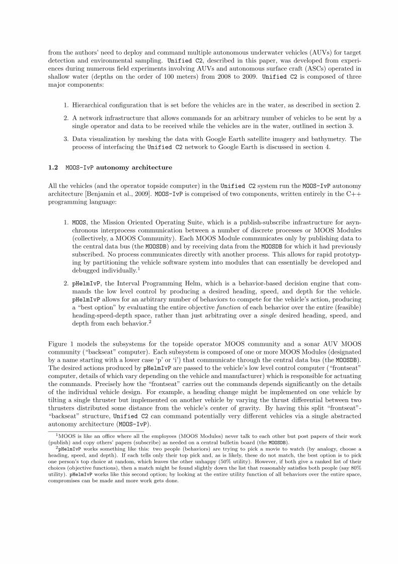
Figure 1 models the subsystems for the topside operator MOOS community and a sonar AUV MOOScommunity (“backseat” computer). Each subsystem is composed of one or more MOOS Modules (designatedby a name starting with a lower case ‘p’ or ‘i’) that communicate through the central data bus (the MOOSDB).The desired actions produced by pHelmIvP are passed to the vehicle’s low level control computer (“frontseat”computer, details of which vary depending on the vehicle and manufacturer) which is responsible for actuatingthe commands. Precisely how the “frontseat” carries out the commands depends significantly on the detailsof the individual vehicle design. For example, a heading change might be implemented on one vehicle bytilting a single thruster but implemented on another vehicle by varying the thrust differential between twothrusters distributed some distance from the vehicle’s center of gravity. By having this split “frontseat”-“backseat” structure, Unified C2 can command potentially very different vehicles via a single abstractedautonomy architecture (MOOS-IvP).
1MOOS is like an office where all the employees (MOOS Modules) never talk to each other but post papers of their work(publish) and copy others’ papers (subscribe) as needed on a central bulletin board (the MOOSDB).
2pHelmIvP works something like this: two people (behaviors) are trying to pick a movie to watch (by analogy, choose aheading, speed, and depth). If each tells only their top pick and, as is likely, these do not match, the best option is to pickone person’s top choice at random, which leaves the other unhappy (50% utility). However, if both give a ranked list of theirchoices (objective functions), then a match might be found slightly down the list that reasonably satisfies both people (say 80%utility). pHelmIvP works like this second option; by looking at the entire utility function of all behaviors over the entire space,compromises can be made and more work gets done.
Sonar AUV MOOS (Backseat) Computer
Hydrophone Array
Main Vehicle Computer
(Manufacturer Specific)
WHOI Micro-Modem
«subsystem»Vehicle Autonomy Control{components = pHelmIvP}
«subsystem»Tracking
{components = p1BTracker, pTrackQuality}
«subsystem»Front Seat Interface
{components = iHuxley, iOceanServerComms, or iOEX}
«subsystem»Communications
{components = pAcommsHandler, pMOOSBridge}
Environmental Sensor
(e.g. CTD)
«subsystem»Sonar Interface and Processing
{components = iDAS, pBearingTrack}
«subsystem»Environmental Sampling
{components = iCTD, pEnvtGrad}
«executable»MOOSDB
IEEE 802.11 Wifi
«subsystem»Navigation
«subsystem»Low level control
Topside MOOS Computer
WHOI Micro-Modem
«subsystem»Communications
{components = pAcommsHandler, pMOOSBridge}
Ship Sensors (e.g. GPS,
Radar)
«executable»MOOSDB
IEEE 802.11 Wifi
«subsystem»Command
{components = iCommander}
«subsystem»Visualization
{components = pMarineViewer, iMOOS2SQL} GEOV Server (Google
Earth Display)
Figure 1: Model of the subsystems of the operator topside (ship-based command computer) and a sonarAutonomous Underwater Vehicle (AUV) (e.g. the Bluefin 21 Unicorn). Each subsystem is comprised ofone or more independent MOOS processes that communicate only through a central data bus (the MOOSDB).While processes do not communicate directly, key implicit dependencies between subsystems are indicatedwith dotted arrows.
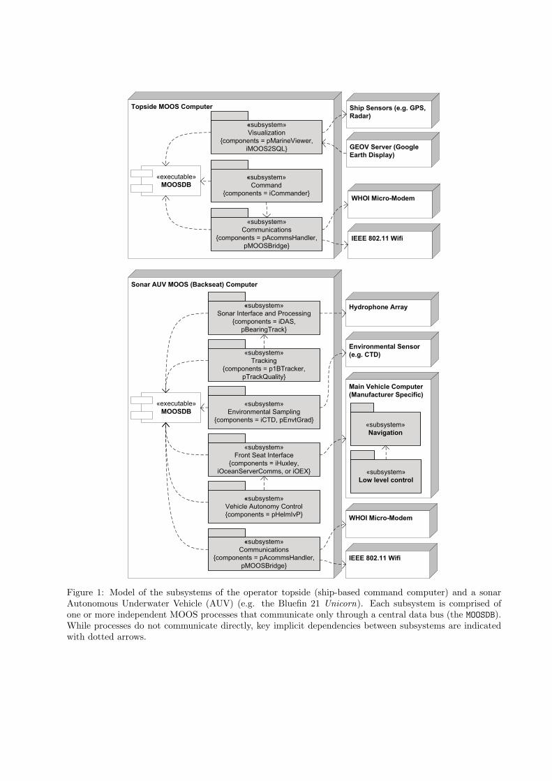
Table 1: Summary of field trials during which Unified C2 was developed and tested. The column markedMessages Used refers to Dynamic Compact Control Language message names unless specified. The exper-iment datum is a location in the southwest corner of the operation region from which all vehicle positionsare referenced using the Universal Transverse Mercator projection with the WGS 84 ellipsoid [NIMA, 2000].
Name Dates Summary Vehicles Messages Used ExperimentDatum
CCLNET08 1.19.08 - 2.1.08 First Engineeringtest for GLINT
AUV: 1 NURC OEX.ASC: 2 Robotic MarineKayaks
PlusNet CCL (DCCL not devel-oped)
44.08892◦N,9.85054◦E
SQUINT08 5.19.08 - 5.23.08 Second Engineer-ing test for GLINT
AUV: 1 NURC OEX.ASC: 2 Robotic MarineKayaks
PlusNet CCL (DCCL not devel-oped)
44.08892◦N,9.85054◦E
GLINT08 7.22.08 - 8.14.08 Interoperability ofmarine vehicles forpassive acoustictarget detection
AUV: 1 NURC OEX,1 Bluefin 21 (Unicorn),1 OceanServer Iver2.ASC: 3 Robotic MarineKayaks
PlusNet CCL (DCCL not devel-oped), compressed CTD mes-sages (precursor to DCCL)
42.5◦N,10.08333◦E
SWAMSI09 3.23.09 - 4.5.09 Mine detection us-ing bistatic acous-tics.
AUV: 2 Bluefin 21(Unicorn, Macrura)
LAMSS DEPLOY,LAMSS STATUS,ACTIVE CONTACT,ACTIVE TRACK, CTD
30.045◦N,85.726◦W
GLINT09 6.29.09-7.21.09 Interoperability ofmarine vehicles forpassive acoustictarget detection
AUV: 1 NURC OEX,1 OceanServer Iver2.ASC: 2 Robotic MarineKayaks
LAMSS DEPLOY,SURFACE DEPLOY,LAMSS STATUS,LAMSS CONTACT,LAMSS TRACK, CTD
42.47◦N,10.9◦E
DURIP09 8.19.09 - 9.02.09 Engineering testfor collabora-tive autonomyand towed arrayimprovements
AUV: 2 Bluefin 21(Unicorn, Macrura).ASC: 2 Robotic MarineKayaks.
LAMSS DEPLOY,SURFACE DEPLOY,LAMSS STATUS,LAMSS CONTACT,LAMSS TRACK, CTD, BTR,ACOUSTIC MOOSPOKE
42.35◦N,70.95◦W
1.3 Field Exercises
All the work involved in developing Unified C2 was motivated by and tested at several field trials spanningfrom 2008 to 2009. These exercises took place in shallow water (depths on the order of 100 meters) andinvolved four different types of AUVs and ASCs, all running the MOOS-IvP autonomy in a frontseat-backseatconfiguration as discussed in section 1.2. These trials are summarized in table 1 and experiences from themwill be referenced throughout the remainder of this paper.
1.4 Prior Art
Traditionally, underwater vehicles are controlled using platform specific interfaces where the vehicles com-municate with the surfaced assets using dedicated wireless ethernet communication channels. Each missionis configured before the dive is initiated. After the vehicle is submerged, status and contact reports are trans-mitted via acoustic modem, and simple re-deploy commands are sent from the topside C2 console, providedsuch maneuvers are allowed in the mission script and coded into the acoutic datagrams. The fixed messageset highly limits the ability of the human operator to command the vehicles while submerged. Also, almostuniformly, the command and control infrastructures have been proprietary and manufacturer-specific. Thus,there is little openly published literature on these systems.
For example, most REMUS vehicles (manufactured by Hydroid) are controlled within this paradigm usingthe REMUS Vehicle Interface Program (VIP) software infrastructure. Similarly, Bluefin Robotics’ AUVs,apart from the MIT LAMSS fleet, are controlled using the Bluefin proprietary topside. Although somecomponents of these systems are common, such as the CCL message coding, they are in general completely
#Communications#Logging
Global
#Vehicle Autonomy Control
AUV
#Vehicle Autonomy Control
ASC
#Front Seat Interface
Bluefin AUV
#Front Seat Interface
OceanServer AUV
#Front Seat Interface
NURC AUV
#Front Seat Interface
Robotic Marine Kayak
+ship name : string
Topside
+name : string = Bobby
Kayak
+name : string = Dee
Kayak
#Tracking#Sonar Interface
Sonar AUV
#Environmental Sampling
Environmental AUV
+name : string = OEX
Ocean Explorer
+name : string = Hammerhead
Iver2
+name : string = Unicorn
Bluefin 21
+name : string = Macrura
Bluefin 21
+name2id() : unsigned int+id2name() : string+id2type() : string
Cruise +datum lat : double = 42.47+datum lon : double = 10.9+safety behaviors
GLINT09
+datum lat : double = 30.045+datum lon : double = -85.753+safety behaviors
SWAMSI09
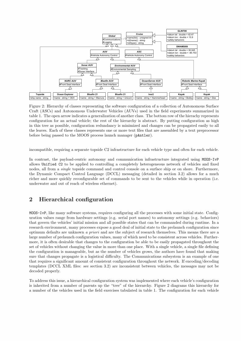
Figure 2: Hierarchy of classes representing the software configuration of a collection of Autonomous SurfaceCraft (ASCs) and Autonomous Underwater Vehicles (AUVs) used in the field experiments summarized intable 1. The open arrow indicates a generalization of another class. The bottom row of the hierachy representsconfiguration for an actual vehicle; the rest of the hierarchy is abstract. By putting configuration as highin this tree as possible, configuration redundancy is minimized and changes can be propagated easily to allthe leaves. Each of these classes represents one or more text files that are assembled by a text preprocessorbefore being passed to the MOOS process launch manager (pAntler).
incompatible, requiring a separate topside C2 infrastructure for each vehicle type and often for each vehicle.
In contrast, the payload-centric autonomy and communication infrastructure integrated using MOOS-IvP
allows Unified C2 to be applied to controlling a completely heterogeneous network of vehicles and fixednodes, all from a single topside command and control console on a surface ship or on shore. Furthermore,the Dynamic Compact Control Language (DCCL) messaging (detailed in section 3.2) allows for a muchricher and more quickly reconfigurable set of commands to be sent to the vehicles while in operation (i.e.underwater and out of reach of wireless ethernet).
2 Hierarchical configuration
MOOS-IvP, like many software systems, requires configuring all the processes with some initial state. Config-uration values range from hardware settings (e.g. serial port names) to autonomy settings (e.g. behaviors)that govern the vehicles’ initial mission and all possible states that can be commanded during runtime. In aresearch environment, many processes expose a good deal of initial state to the prelaunch configuration sinceoptimum defaults are unknown a priori and are the subject of research themselves. This means there are alarge number of prelaunch configuration values, many of which need to be consistent across vehicles. Further-more, it is often desirable that changes to the configuration be able to be easily propagated throughout theset of vehicles without changing the value in more than one place. With a single vehicle, a single file definingthe configuration is manageable, but as the number of vehicles grows, the authors have found that makingsure that changes propagate is a logistical difficulty. The Communications subsystem is an example of onethat requires a significant amount of consistent configuration throughout the network. If encoding/decodingtemplates (DCCL XML files: see section 3.2) are inconsistent between vehicles, the messages may not bedecoded properly.
To address this issue, a hierarchical configuration system was implemented where each vehicle’s configurationis inherited from a number of parents up the “tree” of the hierarchy. Figure 2 diagrams this hierarchy fora number of the vehicles used in the field exercises tabulated in table 1. The configuration for each vehicle

can be thought of as a class that inherits configuration much in the same way as public class inheritance(which expresses an “is-a” relationship) works in object-oriented programming languages (such as C++).For example, in Figure 2, the Ocean Explorer (OEX) is a NURC AUV which is a Sonar AUV, etc. Anyconfiguration for a Sonar AUV is inherited by all NURC AUVs which is then in turn inherited by the OEX.
Examples of the subsystems that are typically configured at each level are given in Figure 2. Cruisesare handled as a class that the Global configuration (i.e., the root of the tree) depends on. Informationcontained in each cruise is specific to the operations of that experiment such as a local datum for geodesicconversions, local obstacles to avoid, and a mapping of the vehicle names to a numeric id number for acousticcommunications.
Since MOOS is limited to accepting plain text configuration files with key/value pairs, this hierarchical config-uration structure is implemented through a series of small text files (that represent each “class” in Figure 2)that are included to the main configuration file via a text preprocessor (splug), which is very similar to theC Preprocessor (cpp). The configuration is kept consistent throughout the vehicles by using version controlsoftware (in our case, Subversion) in the same manner that the source code is kept consistent.
This type of configuration was first developed and tested on ASCs at GLINT08 and then migrated to AUVsby SWAMSI09. The authors have found that ASCs make excellent testbeds for changes to the Unified C2
architecture as they can be reprogrammed while deployed and are at less risk of loss due to errors in thenew system as they do not dive.
3 Network
3.1 Subsea and surface networking
Reliable communications between underwater and surface nodes in the ocean are at best an uncertainty.Underwater communications are only practical using an acoustic carrier due to the rapid attenuation of mostelectromagnetic wavelengths in sea water [Clay and Medwin, 1977]. Acoustics are subject to the variations ofthe physical propagation of sound, are slow (over five orders of magnitude slower than light), and have littleusable bandwidth due to the low frequencies of the carriers, leading to unpredictability and low throughputwhen sending messages below the surface. Above-surface wireless ethernet (wifi) affords much higher bitratesbut is subject to antennae line of sight issues, especially with small masted vehicles bouncing in the waves.In the field trials given in table 1, the authors have found the range of acoustic communications to often besubstantially better (factor of two or more) than the wifi connection to Bluefin 21 AUVs. However, ship-to-ship or ship-to-buoy networking over ranges of several kilometers can be reasonably reliable if properlyinstalled. In the authors’ experience, reliable communications are much more important to successful fieldoperation of robotic vehicles than fast communications.
Unified C2 networking has evolved from a single-hop underwater network to a single-hop underwater net-work with (potentially) multi-hop above-water network. This allows the operator’s commands to a subsurfacenode to be forwarded to the nearest “gateway,” which is either an acoustic modem on the ship, or a buoy orautonomous surface craft (ASC) with a modem. The last option allows the most flexibility, as the ASC cantransit to improve its range to the underwater vehicle and improve the chance of reception.
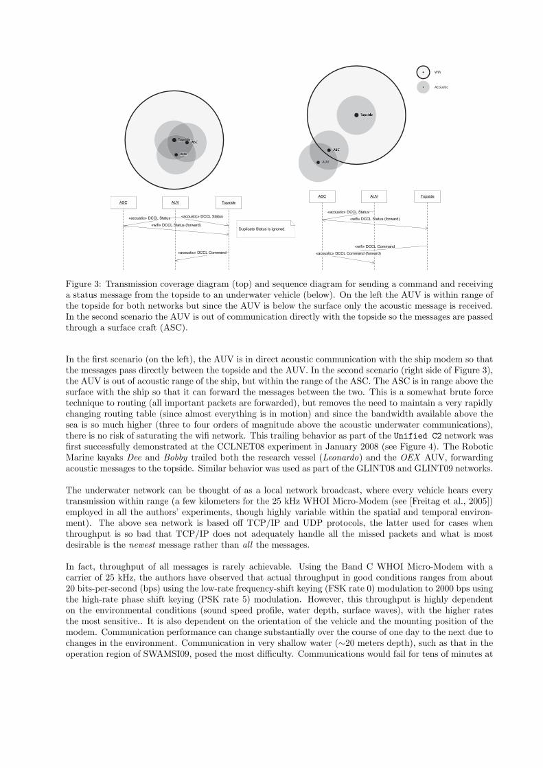
One behavior that works well for cases when high throughput from the underwater vehicle is needed is tohave an ASC trail the AUV by a short distance, making the acoustic transmission closer to vertical (as wellas a shorter distance) and reducing the refraction (since the water is much more stratified in the verticalthan the horizontal) and multiple reflections (multipath) that destroy acoustic packets. Figure 3 shows twoscenarios for a ship (topside), an AUV and an ASC, where the topside commander wishes to send a commandto the AUV as well as receive a status message (e.g., position, orientation, speed, health) from the AUV.
TopsideASCASCASC
AUV
TopsideASCASCASCASCASCASCASCASC
TopsideASCASCASCASC
AUVAUV
AUV TopsideASC
«acoustic» DCCL Status«acoustic» DCCL Status
«wifi» DCCL Status (forward)Duplicate Status is ignored.
«acoustic» DCCL Command
Topside
ASCASCASC
AUV
TopsideTopside
ASCASCASCASCASCASCASCASC
TopsideTopsideTopside
Wi
Acoustic
AUV TopsideASC
«acoustic» DCCL Status
«wifi» DCCL Status (forward)
«wifi» DCCL Command
«acoustic» DCCL Command (forward)
Figure 3: Transmission coverage diagram (top) and sequence diagram for sending a command and receivinga status message from the topside to an underwater vehicle (below). On the left the AUV is within range ofthe topside for both networks but since the AUV is below the surface only the acoustic message is received.In the second scenario the AUV is out of communication directly with the topside so the messages are passedthrough a surface craft (ASC).
In the first scenario (on the left), the AUV is in direct acoustic communication with the ship modem so thatthe messages pass directly between the topside and the AUV. In the second scenario (right side of Figure 3),the AUV is out of acoustic range of the ship, but within the range of the ASC. The ASC is in range above thesurface with the ship so that it can forward the messages between the two. This is a somewhat brute forcetechnique to routing (all important packets are forwarded), but removes the need to maintain a very rapidlychanging routing table (since almost everything is in motion) and since the bandwidth available above thesea is so much higher (three to four orders of magnitude above the acoustic underwater communications),there is no risk of saturating the wifi network. This trailing behavior as part of the Unified C2 network wasfirst successfully demonstrated at the CCLNET08 experiment in January 2008 (see Figure 4). The RoboticMarine kayaks Dee and Bobby trailed both the research vessel (Leonardo) and the OEX AUV, forwardingacoustic messages to the topside. Similar behavior was used as part of the GLINT08 and GLINT09 networks.
The underwater network can be thought of as a local network broadcast, where every vehicle hears everytransmission within range (a few kilometers for the 25 kHz WHOI Micro-Modem (see [Freitag et al., 2005])employed in all the authors’ experiments, though highly variable within the spatial and temporal environ-ment). The above sea network is based off TCP/IP and UDP protocols, the latter used for cases whenthroughput is so bad that TCP/IP does not adequately handle all the missed packets and what is mostdesirable is the newest message rather than all the messages.
In fact, throughput of all messages is rarely achievable. Using the Band C WHOI Micro-Modem with acarrier of 25 kHz, the authors have observed that actual throughput in good conditions ranges from about20 bits-per-second (bps) using the low-rate frequency-shift keying (FSK rate 0) modulation to 2000 bps usingthe high-rate phase shift keying (PSK rate 5) modulation. However, this throughput is highly dependenton the environmental conditions (sound speed profile, water depth, surface waves), with the higher ratesthe most sensitive.. It is also dependent on the orientation of the vehicle and the mounting position of themodem. Communication performance can change substantially over the course of one day to the next due tochanges in the environment. Communication in very shallow water (∼20 meters depth), such as that in theoperation region of SWAMSI09, posed the most difficulty. Communications would fail for tens of minutes at

Figure 4: GEOV screenshot showing ASCs Bobby and Dee trailing the OEX AUV to improve networkingthroughput at the CCLNET08 experiment. Acoustic communications are only robust over short distanceswith largely vertical propagation, which makes these “mobile gateways” effective, as they can always maintaina relatively short distance to the AUV. The ASCs were commanded to trail at 100 meters behind the AUVat 170◦ and 190◦ relative to the AUV’s bow. The ASCs were also running a high priority collision avoidancebehavior with the RV Leonardo (“leo”), which accounts for the shift to port from the normative trackingpositions.
a time, especially at ranges of more than several hundred meters. However, in GLINT08 with a water depthof 100 meters, even high rate (PSK rate 5) transmissions would occur successfully at ranges up to 1.6 km.To maximize the throughput, but ensure some consistent messaging, the authors will command the vehiclesto alternatingly send messages at low and high rates.
All messages are prioritized to compensate for the reality of low and variable throughput. The message withthe highest priority is sent at each opportunity provided by the medium access control (MAC) scheme. Thepriorities grow in the time since the last message of that type was sent. Thus, higher priority messagesdo not continuously overwhelm lower priority messages. This is implemented through a set of queues: onequeue for each DCCL message (e.g. LAMSS STATUS has one queue, ACTIVE CONTACTS has another).Each queue i has a priority value (Pi(t)) which is calculated using
Pi(t) = Vi
(
t− τi
ttli
)
(1)
where Vi is the base value of the queue (i.e. the importance of that type of message), ttli is the time-to-live(in seconds) of messages in that queue, τi is the last time a message was sent from the ith queue and t is thecurrent time. Messages with a short ttl are presumably more time sensitive, so their priorities grow fasterthan messages with a longer ttl. When the MAC scheme permits a message to be sent, the queue is chosenwith the highest P (t).
One example of why this dynamic growth of priorities is desirable is during a subsea detection. The AUVgenerates track and contact reports (high priority messages) for the detected object, but the operator stilldesires an occasional lower priority status message to ensure the vehicle is performing correctly. Werepriorities not to grow, the operator would never receive a status message while track reports were beinggenerated.
Messages received from underwater nodes are forwarded by the surface nodes so that all interested parties(typically all the assets in the experiment) can log and use these data. This allows for redundancy whencertain vehicles are out of range of the initial sender.
3.2 Dynamic Compact Control Language (DCCL)
The Dynamic Compact Control Language (DCCL) provides a structure language for defining fixed-lengthshort messages primarily to be sent through an acoustic modem (but which can be sent through TCP/IPor UDP as well). The messages are configured in XML and are intended to be easily reconfigurable, unlikethe original CCL framework (see [Stokey et al., 2005]) used in the REMUS vehicles that DCCL aims toreplace. DCCL can operate within a CCL network, as the most significant byte (or CCL ID) is 0x20. DCCLmessages can be easily reconfigured because they are defined in plain text XML files which are encoded usinga set of standard rules given in Table 2. Creating a new CCL message, on the other hand, requires definingeach field and its encoding in software code and then testing to ensure its correctness. By using an XMLschema and other structural checks, DCCL greatly reduces the chance of undetected error when defining newmessages. A more in-depth explanation of DCCL, including example XML files, can be found in [Schneiderand Schmidt, 2010]. The source code and documentation for DCCL, provided as the C++ library libdccl, isavailable as part of the open-source goby-acomms project at http://launchpad.net/goby.
One example that demonstrates the flexibility of DCCL occured in SWAMSI09. In this experiment, twoAUVs were to perform bistatic acoustic detection of mine-like targets on the seafloor. In order to do this,both AUVs needed to traverse a circular pattern around the potential target, maintaining a constant bistaticangle. However, entering into this collaboration and maintaining the correct angle required handshaking anddata transfer between both vehicles. At the time of the experiment there was no available fields in the currentmessage set to perform this handshake. By adding some new fields (i.e. several lines of XML text) to theLAMSS STATUS message, the vehicles were able to perform the handshake underwater as needed. This wouldnot have been possible with the hard-coded CCL messages without substantially more planning, coding, andtesting.
DCCL is similar to the ASN.1 unaligned Packed Encoding Rules [Dubuisson and Fouquart, 2000]. DCCLmessages are packed based on bit boundaries (as opposed to bytes or words) determined with knowledge ofthe XML file. They are not self-describing, as this would be prohibitively expensive in terms of data use.Thus, the sender and receiver must have a copy of the same XML file for decoding a given message. Also,each message is defined by an identification number that must be unique within a network.
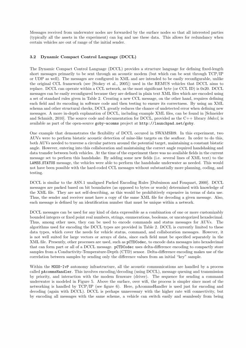
DCCL messages can be used for any kind of data expressible as a combination of one or more customizablybounded integers or fixed point real numbers, strings, enumerations, booleans, or uncategorized hexadecimal.Thus, among other uses, they can be used to encode commands and status messages for AUVs. Thealgorithms used for encoding the DCCL types are provided in Table 2. DCCL is currently limited to thesedata types, which cover the needs for vehicle status, command, and collaboration messages. However, itis not well suited for large vectors or arrays of data, since each field must be specified separately in theXML file. Presently, other processes are used, such as pCTDCodec, to encode data messages into hexadecimalthat can form part or all of a DCCL message. pCTDCodec uses delta-difference encoding to compactly storesamples from a Conductivity-Temperature-Depth (CTD) sensor. Delta-difference encoding makes use of thecorrelation between samples by sending only the difference values from an initial “key” sample.
Within the MOOS-IvP autonomy infrastructure, all the acoustic communications are handled by a processcalled pAcommsHandler. This involves encoding/decoding (using DCCL), message queuing and transmissionby priority, and interaction with the modem firmware (driver). The sequence for sending a commandunderwater is modeled in Figure 5. Above the surface, over wifi, the process is simpler since most of thenetworking is handled by TCP/IP (see figure 6). Here, pAcommsHandler is used just for encoding anddecoding (again with DCCL). DCCL is perhaps unnecessary with the higher rate wifi connectivity, butby encoding all messages with the same scheme, a vehicle can switch easily and seamlessly from being
Table 2: Formulas for encoding the DCCL types.
DCCL Type Size (bits) Encodea
<bool> 2 xenc =
{
2 if x is true1 if x is false0 if x is undefined
<enum> ⌈log2(1 +∑
ǫi)⌉ xenc =
{
i+ 1 if x ∈ {ǫi}0 otherwise
<string> length · 8 ASCIIb
<int> ⌈log2(max−min+ 2)⌉ xenc =
{
nint(x−min) + 1 if x ∈ [min,max]0 otherwise
<float> ⌈log2((max−min) · 10precision + 2)⌉ xenc =
{
nint((x−min) · 10precision) + 1 if x ∈ [min,max]0 otherwise
<hex> num bytes · 8 xenc = x
· x is the original (and decoded) value; xenc is the encoded value.· min, max, length, precision, num bytes are specified for each relevant field in the XML file. ǫi is the ith enumeration value(where i = 0, 1, 2, . . .).· nint(x) means round x to the nearest integer.
a for all types except <string> and <hex>, if data are not provided or they are out of range (e.g. x > max), they are encodedas zero (xenc = 0) and decoded as not-a-number (NaN).
b the end of the string is padded with zeros to length before encoding if necessary.
commanded on the surface to being commanded below the surface.
The command process (iCommander) is an NCurses terminal graphical user interface that allows a user totype in values for the fields for any number of DCCL messages. Since the fields displayed to the humanoperator for entry are directly read from the XML message files, any change to the command message contentsare immediately available to the operator without changing software code. In the authors’ experience it ispreferable to avoid changing code on experiments whereever possible without sacrificing the ability to makechanges to the messages (e.g., to allow a new experiment to take place).
DCCL loads the message configuration (given as XML) into C++ objects at runtime. Thus, when a mes-sage is changed, the vehicle and topside software needs merely to be restarted, not recompiled, for thechange to propagate through the communications software (pAcommsHandler) and the command software(iCommander). This is advantageous for embedded computers, such as those deployed on marine vehicles,since compilation can be a time consuming process.
The authors have developed about a dozen DCCL messages that are widely used in our experiments, as wella number of test messages. The messages used in field trials are summarized in Table 3. They are brokeninto three rough categories: Data, Command, and Collaboration. Data messages are sent from the vehiclesto the topside operator with some type of measured or calculated data. Commands are sent to change themission state of the vehicles. Collaboration messages are sent between robots to provide data or handshakingrelevant to a multi-vehicle experiment.
3.3 Network examples
Figure 7 shows the network connectivity for a simple two-AUV / no-ASC experiment (SWAMSI09). Thetopside (through a buoy) is connected to the vehicles by an acoustic network using the WHOI Micro-Modem.A wifi network (not shown) is used to upload configuration and code changes and download data logs, butthis is primarily done before the day’s operations. Once the vehicle is underway, the vehicles are deployedand redeployed through the acoustic network alone.
Figure 8 gives the network connectivity for a larger experiment with both surface and subsea nodes(GLINT08/09). This network allows forwarding of messages through mobile gateways (the ASCs) andvisualization of data shoreside via the internet and GEOV.
Topside MOOS Computer AUV MOOS Computer
iCommander MOOSDB pAcommsHandler WHOI Micro-Modem pAcommsHandlerWHOI Micro-ModemOperator pAcommsPoller
types commands
OUT_COMMAND
OUT_COMMAND
$CCCYC (Poll)
$CADRQ (Data request)
$CCTXD (Transmit data)
Acoustic PSK/FSK Data
Acoustic Ack
$CAACK (Acknowledgement)
$CARXD (Receive data)
pHelmIvP
ACOMMS_ACK
ACOMMS_ACKdisplay ack
IN_COMMAND
DCCL Message encodedand queued.
MOOSDB
Message decoded.
IN_COMMAND
Message flushed
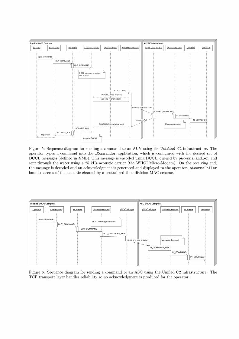
Figure 5: Sequence diagram for sending a command to an AUV using the Unified C2 infrastructure. Theoperator types a command into the iCommander application, which is configured with the desired set ofDCCL messages (defined in XML). This message is encoded using DCCL, queued by pAcommsHandler, andsent through the water using a 25 kHz acoustic carrier (the WHOI Micro-Modem). On the receiving end,the message is decoded and an acknowledgment is generated and displayed to the operator. pAcommsPollerhandles access of the acoustic channel by a centralized time division MAC scheme.
Topside MOOS Computer ASC MOOS Computer
iCommander MOOSDB pAcommsHandler pAcommsHandlerOperator
types commands
OUT_COMMAND
OUT_COMMAND
IN_COMMAND_HEX
pHelmIvP
IN_COMMAND
MOOSDB
Message decoded.
IN_COMMAND
OUT_COMMAND_HEX
pMOOSBridge
DCCL Message encoded.
pMOOSBridge
IEEE 802.11b 2.4 GHz
Figure 6: Sequence diagram for sending a command to an ASC using the Unified C2 infrastructure. TheTCP transport layer handles reliability so no acknowledgment is produced for the operator.
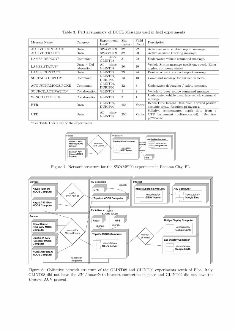
Table 3: Partial summary of DCCL Messages used in field experiments
Message Name CategoryExperimentsUseda
Size(bytes)
FieldCount
Description
ACTIVE CONTACTS Data SWAMSI09 32 22 Active acoustic contact report message.
ACTIVE TRACKS Data SWAMSI09 32 20 Active acoustic tracking message.
LAMSS DEPLOYb CommandAll sinceGLINT08
31 22 Underwater vehicle command message.
LAMSS STATUSbData / Col-laboration
All sinceGLINT08
26 20Vehicle Status message (position, speed, Eulerangles, autonomy state)
LAMSS CONTACT Data GLINT09 29 24 Passive acoustic contact report message.
SURFACE DEPLOY CommandGLINT09,DURIP09
13 10 Command message for surface vehicles.
ACOUSTIC MOOS POKE CommandGLINT09,DURIP09
32 3 Underwater debugging / safety message.
SOURCE ACTIVATION Collaboration GLINT09 5 2 Vehicle to buoy source command message.
WINCH CONTROL Collaboration GLINT09 3 1Underwater vehicle to surface vehicle commandmessage.
BTR DataGLINT09,DURIP09
256 VariesBeam-Time Record Data from a towed passiveacoustic array. Requires pBTRCodec.
CTD DataAll sinceGLINT08
256 VariesSalinity, temperature, depth data from aCTD instrument (delta-encoded). RequirespCTDCodec.
a See Table 1 for a list of the experiments.
Subsea RV Endeavor
Topside MOOS Computer
«executable»GEOV Server
Lab Display Computer
«executable»Google Earth
Bluefin 21 AUV
(Unicorn) MOOS
ComputerGPS
«serial»
Bluefin 21 AUV
(Macrura) MOOS
Computer
«acoustic»Micro-Modem
«wired»ethernet
Figure 7: Network structure for the SWAMSI09 experiment in Panama City, FL.
Subsea
Surface
RV Alliance
RV Leonardo Internet
http://aubergine.whoi.edu
Topside MOOS Computer
«executable»GEOV Server
Lab Display Computer
Bridge Display Computer
«executable»Google Earth
«executable»Google Earth
«wired»ethernet
Kayak (Elanor)
MOOS Computer
Kayak ASC (Dee)
MOOS Computer
Bluefin 21 AUV
(Unicorn) MOOS
Computer
NURC AUV (OEX)
MOOS Computer
Topside MOOS Computer
«wifi»5.0GHz WiLan
«acoustic»Edgetech
GPS
«serial»
GPSRadar
«serial» «serial»
«executable»GEOV Server
Any Computer
«executable»Google Earth
OceanServer
Iver2 AUV MOOS
Computer
«wifi»IEEE 802.11
«acoustic»Micro-Modem
Figure 8: Collective network structure of the GLINT08 and GLINT09 experiments south of Elba, Italy.GLINT08 did not have the RV Leonardo-to-Internet connection in place and GLINT09 did not have theUnicorn AUV present.
GEOV Client
GEOV Server
«executable»Web Server (Apache 2)
«executable»Web Scripting (php 5)
«executable»Database (MySQL 5)
«executable»Web Browser (e.g. Firefox)
«executable»Google Earth
Other Google
Earth Content
«html» «kml»
«kml»
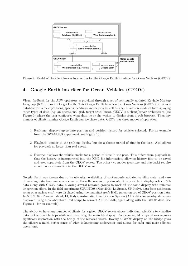
Figure 9: Model of the client/server interaction for the Google Earth interface for Ocean Vehicles (GEOV).
4 Google Earth interface for Ocean Vehicles (GEOV)
Visual feedback for the AUV operators is provided through a set of continually updated Keyhole MarkupLanguage (KML) files in Google Earth. This Google Earth Interface for Ocean Vehicles (GEOV) provides adatabase for vehicle positions, speeds, headings and depths as well as a set of add-on modules for displayingother types of data (e.g, an operational grid, target track lines). GEOV is a client/server architecture (seeFigure 9) where the user configures what data he or she wishes to display from a web browser. Then anynumber of clients running Google Earth can see these data. GEOV has three modes of operation:
1. Realtime: displays up-to-date position and position history for vehicles selected. For an examplefrom the SWAMSI09 experiment, see Figure 10.
2. Playback: similar to the realtime display but for a chosen period of time in the past. Also allowsfor playback at faster than real speed.
3. History: displays the vehicle tracks for a period of time in the past. This differs from playback inthat the history is incorporated into the KML file information, allowing history files to be savedand used separately from the GEOV server. The other two modes (realtime and playback) requirea continuous connection to the GEOV server.
Google Earth was chosen due to its ubiquity, availability of continuously updated satellite data, and easeof meshing data from numerous sources. On collaborative experiments, it is possible to display other KMLdata along with GEOV data, allowing several research groups to work off the same display with minimalintegration effort. In the field experiment SQUINT08 (May 2008: La Spezia, SP, Italy), data from a sidescansonar on a surface craft were displayed using the manufacturer’s KML parser on top of GEOV position data.In GLINT08 (Pianosa Island, LI, Italy), Automatic Identification System (AIS) data for nearby ships wasdisplayed using a collaborator’s Perl script to convert AIS to KML, again along with the GEOV data (seeFigure 11 for an example).
The ability to have any number of clients for a given GEOV server allows individual scientists to visualizedata on their own laptops while not disturbing the main lab display. Furthermore, AUV operations requiressignificant interaction with the bridge of the research vessel. Having a GEOV display on the bridge givesthe officers a much better sense of what is happening underwater and allows for safer and more efficientoperations.
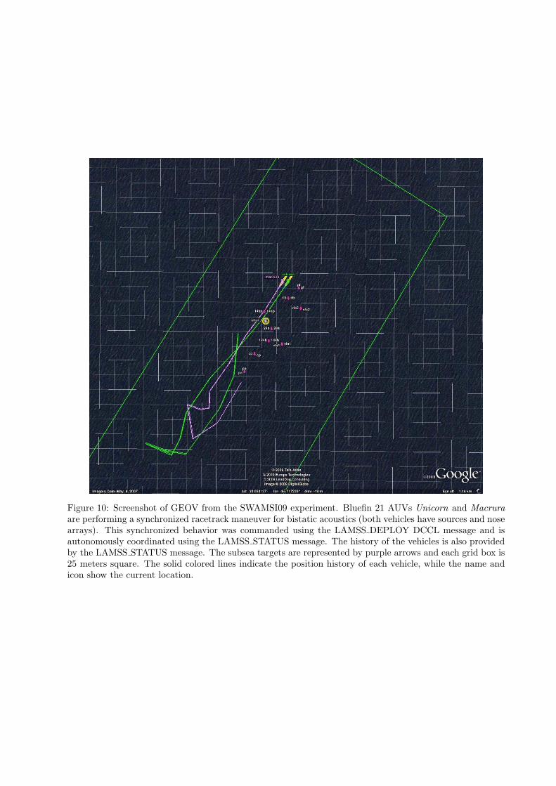
Figure 10: Screenshot of GEOV from the SWAMSI09 experiment. Bluefin 21 AUVs Unicorn and Macrura
are performing a synchronized racetrack maneuver for bistatic acoustics (both vehicles have sources and nosearrays). This synchronized behavior was commanded using the LAMSS DEPLOY DCCL message and isautonomously coordinated using the LAMSS STATUS message. The history of the vehicles is also providedby the LAMSS STATUS message. The subsea targets are represented by purple arrows and each grid box is25 meters square. The solid colored lines indicate the position history of each vehicle, while the name andicon show the current location.
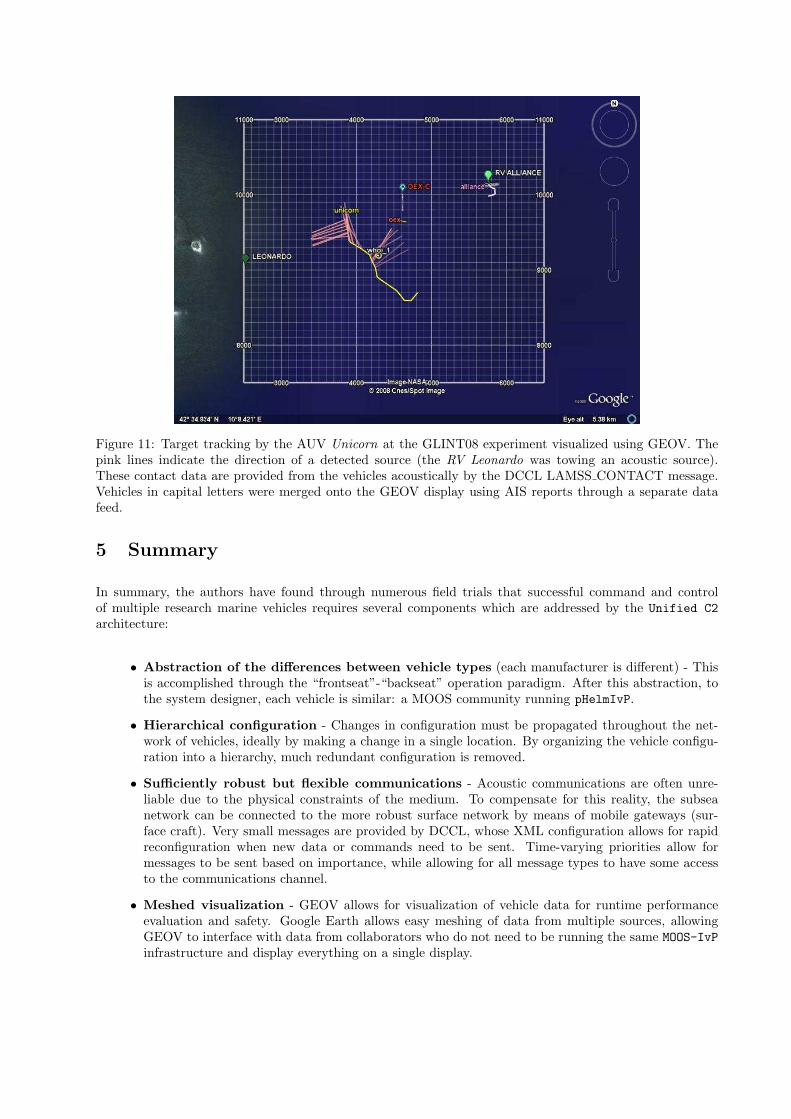
Figure 11: Target tracking by the AUV Unicorn at the GLINT08 experiment visualized using GEOV. Thepink lines indicate the direction of a detected source (the RV Leonardo was towing an acoustic source).These contact data are provided from the vehicles acoustically by the DCCL LAMSS CONTACT message.Vehicles in capital letters were merged onto the GEOV display using AIS reports through a separate datafeed.
5 Summary
In summary, the authors have found through numerous field trials that successful command and controlof multiple research marine vehicles requires several components which are addressed by the Unified C2
architecture:
• Abstraction of the differences between vehicle types (each manufacturer is different) - Thisis accomplished through the “frontseat”-“backseat” operation paradigm. After this abstraction, tothe system designer, each vehicle is similar: a MOOS community running pHelmIvP.
• Hierarchical configuration - Changes in configuration must be propagated throughout the net-work of vehicles, ideally by making a change in a single location. By organizing the vehicle configu-ration into a hierarchy, much redundant configuration is removed.
• Sufficiently robust but flexible communications - Acoustic communications are often unre-liable due to the physical constraints of the medium. To compensate for this reality, the subseanetwork can be connected to the more robust surface network by means of mobile gateways (sur-face craft). Very small messages are provided by DCCL, whose XML configuration allows for rapidreconfiguration when new data or commands need to be sent. Time-varying priorities allow formessages to be sent based on importance, while allowing for all message types to have some accessto the communications channel.
• Meshed visualization - GEOV allows for visualization of vehicle data for runtime performanceevaluation and safety. Google Earth allows easy meshing of data from multiple sources, allowingGEOV to interface with data from collaborators who do not need to be running the same MOOS-IvPinfrastructure and display everything on a single display.
Together these elements fight the ever increasing complexity inherent in multi-vehicle robotic systems tocreate a manageable, yet readily reconfigurable, system.
Acknowledgments
This work was supported by the Office of Naval Research, Grants N00014-1-08-1-0011 (B. Headrick, ProgramManager) and N00014-1-08-1-0013 (E. Livingston, Program Manager). The authors also greatly appreciatethe contributions by NURC of logistics support and ship time, without which these experiments would nothave been possible.
The authors acknowledge the crews of the CRV Leonardo, NRV Alliance, RV Endeavor, and RV Resolution
for their excellent operations support. They also thank the many collaborators in these field exercises fromNUWC, NURC, and WHOI.
References
Benjamin, M. R., Leonard, J. J., Schmidt, H., and Newman, P. M. (2009). An overview of moos-ivp and abrief users guide to the ivp helm autonomy software. Technical Report MIT-CSAIL-TR-2009-028, MIT.Available at http://hdl.handle.net/1721.1/45569, accessed December 1, 2009.
Clay, C. and Medwin, H. (1977). Acoustical oceanography: Principles and applications. John Wiley & Sons,Inc.
Crowell, J. (2006). Small auv for hydrographic applications. In Proceedings of the IEEE Oceans Conference
2006, Boston, MA.
Dubuisson, O. and Fouquart, P. (2000). ASN. 1: communication between heterogeneous systems. MorganKaufmann Pub.
Freitag, L., Grund, M., Singh, S., Partan, J., Koski, P., and Ball, K. (2005). The WHOI Micro-Modem:an acoustic communications and navigation system for multiple platforms. In Proceedings of the IEEE
Oceans Conference 2005, Washington, DC.
NIMA (2000). Department of defense world geodetic system 1984: Its definition and relationships withlocal geodetic systems. second edition, amendment 1. Technical Report TR8350.2, NIMA. Available athttp://earth-info.nga.mil/GandG/publications/tr8350.2/wgs84fin.pdf, accessed January 3, 2010.
Schneider, T. and Schmidt, H. (2010). The Dynamic Compact Control Language: A compact marshallingscheme for acoustic communications. In Proceedings of the IEEE Oceans Conference 2010, Sydney,Australia.
Stokey, R., Freitag, L., and Grund, M. (2005). A Compact Control Language for AUV acoustic communi-cation. In Proceedings of the IEEE Oceans Conference 2005, Brest, France.


![Interoperable and Unified Multimedia Retrieval]{Interoperable and Unified Multimedia Retrieval in Distributed and Heterogeneous Environments](https://img.pdfslide.net/doc/110x75/545d3f5ab0af9fb32c8b4e29/interoperable-and-unified-multimedia-retrievalinteroperable-and-unified-multimedia-retrieval-in-distributed-and-heterogeneous-environments.jpg)