Embed Size (px)
Citation preview
Page 1 of 58
UNIT – 1
CPU AND MEMORY
PART - A
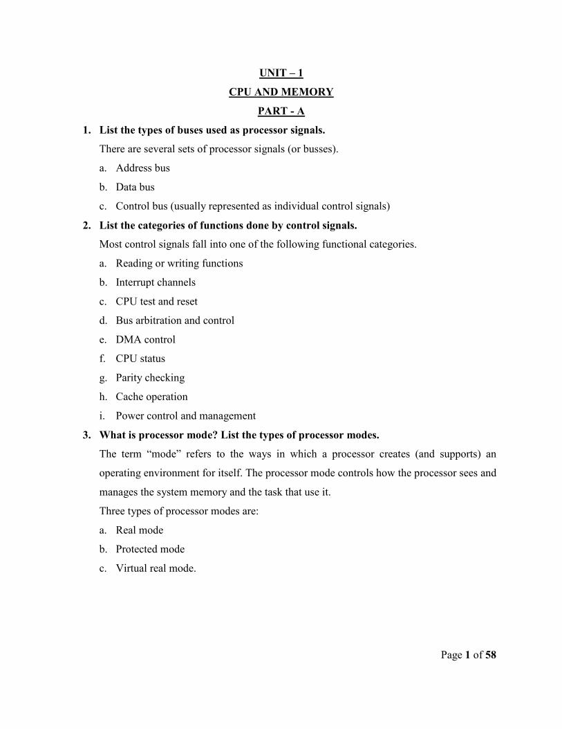
1. List the types of buses used as processor signals.
There are several sets of processor signals (or busses).
a. Address bus
b. Data bus
c. Control bus (usually represented as individual control signals)
2. List the categories of functions done by control signals.
Most control signals fall into one of the following functional categories.
a. Reading or writing functions
b. Interrupt channels
c. CPU test and reset
d. Bus arbitration and control
e. DMA control
f. CPU status
g. Parity checking
h. Cache operation
i. Power control and management
3. What is processor mode? List the types of processor modes.
The term “mode” refers to the ways in which a processor creates (and supports) an
operating environment for itself. The processor mode controls how the processor sees and
manages the system memory and the task that use it.
Three types of processor modes are:
a. Real mode
b. Protected mode
c. Virtual real mode.
Page 2 of 58
4. What is real mode?
The mode in which the original Intel 8088 chip functions is called as real mode. The real
mode has the advantage of speed. But it have some limitations in accessing memory(1
MB limit). The real mode is used by DOS and standard DOS applications.
5. What is protected mode?
It is the most powerful mode than real mode which offers support to virtual memory. It
also supports full access to all the system’s memory (No 1 MB limit). It is used in
modern multitasking OS.
6. What is virtual real mode?
The processor mode which emulates the real mode from within the protected mode and
allows DOS programs to run.
Virtual real mode is what is used when you use a DOS window or run a DOS game in
Windows 98/Me.
7. Distinguish CISC and RISC.
CISC RISC
1. CISC stands for Complex Instruction
Set Computing.
1. RISC stands for Reduced Instruction
Set Computing.
2. The compiler is ease of access. 2. The RISC emphasizes compiler
complexity.
3. The CISC emphasizes greater
hardware complexity.
3. The processor is simple to understand.
4. The number of general purpose
register is less when compared to
RISC.
4. The RISC processors have large
number of general purpose registers.
5. Pipelining implementation is not
easy.
5. Pipelining can be implemented easily.
6. Large amount of different and
complex instructions.
6. Fewer, simpler and faster instructions.
Page 3 of 58
8. Discuss processor speed.
The processor’s speed is a function of several critical factors. The design dictates the
internal timing requirements that limit the maximum speed the processor can handle.
Speed is also influenced by manufacturing factors such as the circuit size and die size.
9. What is superscalar architecture?
Superscalar architecture refers to the use of multiple execution units to allow the CPU to
process more than one instruction simultaneously with every clock cycle.
10. What is pipelining and super pipelining?
The pipelining (instruction pipelining) is a technique that allows a new instruction to start
processing while a current instruction is still being processed.
The superpipelining is generally regarded an improvement over regular pipelining by
making the pipeline longer (with more stages), each stage performs less work and the
processor can be scaled to a higher clock frequency.
11. What is multiprocessing?
Multiprocessing is the technique of running a system with more than one processor. For
example, when we want to double the system performance, we can use two processors
instead of one.
Multiprocessing is managed by the operating system, which allocates different tasks to be
performed by the various processors in the system.
12. What is symmetric multiprocessing and asymmetric multiprocesing?
Asymmetric multiprocessing designates some processors to perform system tasks only
and the others to run applications only.
Symmetric multiprocessing allows either system or user tasks to run on any processor.
13. What is CPU overclocking?
Overclocking is basically the practice of reconfiguring a PC to operate a CPU at a higher
clock speed (or bus speed) than the particular CPU has been specified for.
The higher clock speed should increase the CPU’s performance without damaging the
CPU or reducing its working life.
14. What are the issues of over clocking?
Trouble in any one of these elements will result in overclocking problems.
Page 4 of 58
a. CPU issues
b. Motherboard issues
c. RAM issues
d. Cooling issues
15. What are the potential pitfalls associated with CPU overclocking?
All the 3 pitfalls are heat related.
a. Intermittent operation
b. Shortened life span
c. Outright failure
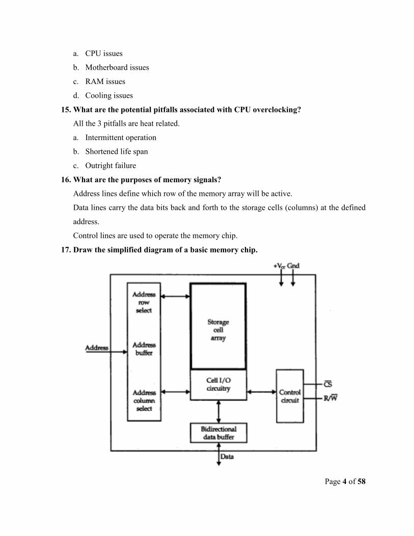
16. What are the purposes of memory signals?
Address lines define which row of the memory array will be active.
Data lines carry the data bits back and forth to the storage cells (columns) at the defined
address.
Control lines are used to operate the memory chip.
17. Draw the simplified diagram of a basic memory chip.
Page 5 of 58
18. What is SIMM?
Single In-Line Memory Module (SIMM) is a light , small and can hold anywhere
between 1 MB and 16 MB of RAM (depending on the module’s vintage).
19. What is base memory?
The memory of size 1 MB that can be addressed by the original PCs that uses
microprocessors is known as base memory (or) real mode memory.
20. What are the types of memory?
The types of memory are:
a. BEDO (Burst Extended Data Output RAM)
b. CDRAM (Cached DRAM)
c. DDR SDRAM
d. DRAM
e. EDO RAM (Extended Data Out RAM)
f. EDRAM (Enhanced DRAM)
g. FPM DRAM(Fast Page Mode DRAM)
h. RDRAM (Rambus DRAM)
i. SDRAM(Synchronous or Synchronized DRAM)
j. SGRAM(Synchronous Graphics RAM)
k. SRAM
l. VRAM(Video RAM)
m. WRAM(Windows RAM)
21. What are the types of memory techniques?
The various memory techniques are:
a. Paged memory
b. Interleaved memory
c. Memory cache
d. Shadow memory
22. What is paged memory?
The paged memory approach basically divides system RAM into small groups (or pages)
from 512 bytes to several KB long.

Page 6 of 58
Memory management circuitry on the motherboard allows subsequent memory accesses
on the same page to be accomplished with zero wait states.
23. What is interleaved memory?
Interleaved memory combines two banks of memory into one. This technique provides
better performance than paged memory. The first portion is “even”, while the second
portion is “odd” – so memory contents are alternated between these two areas.
24. What is memory cache?
Memory cache is a small amount (anywhere between 8 KB to 1MB) of very fast memory
such as SRAM that forms an interface between the CPU and ordinary DRAM.
25. What is shadow memory?
Beginning with the i386 class computers, some designs employed a memory technique
called shadowing. ROM contents are loaded into an area of fast RAM during system
initialization and then the computer maps the fast RAM into memory locations used by
the ROM devices. Information is taken from “Shadowed ROM” instead of the actual
ROM chip.
PART B
1. Explain the processor modes.
• mode definition and list the types of mode.
• also discuss about real mode, protected mode and virtual real mode.
refer Stephen J-Bigelow-”Troubleshooting-Maintaining & repairing of PCs” page no:
430
2. Explain Modern CPU concepts.
• CISC and RISC definition and differences.
• Circuit size and die size.
• Processor speed,
• version,
• power management,
• processor cooling
• system clocks
Page 7 of 58
• processor packages
refer Stephen J-Bigelow-”Troubleshooting-Maintaining & repairing of PCs” page no:
431
3. Discuss the architectural performance features.
• Superscalar architecture
• Pipelining
• Superpipelining
• Speculative execution and branch prediction
• Dynamic execution
• Register renaming
• Multiprocessing
• Multimedia extensions
refer Stephen J-Bigelow-”Troubleshooting-Maintaining & repairing of PCs” page no:
436
4. What is CPU over clocking? Discuss the over clocking requirements.
• Definition
• Requirements for overclocking
• CPU issues
• Motherboard issues
• RAM issues
• Cooling issues
• Potential pitfalls in the overclocking the CPU.
refer Stephen J-Bigelow-”Troubleshooting-Maintaining & repairing of PCs” page no:
481
5. Explain the steps for over clocking the system.
• Reading the instruction to handle motherboard
• Markings on motherboard
• Clock speed and settings referring
• Supervising the cooling unit
• Checking the jumper setting
Page 8 of 58
• CMOS setup verification
refer Stephen J-Bigelow-”Troubleshooting-Maintaining & repairing of PCs” page
no:483
6. Explain over clocking the Intel processor.
• Overclocking the Intel Pentium
• Overclocking the Intel Celeron
• Overclocking the Intel Pentium II/III
• Overclocking the CYRIX 6X86
refer Stephen J-Bigelow-”Troubleshooting-Maintaining & repairing of PCs” page no:
487
7. Explain logical memory organization.
• Conventional memory
• Extended memory
• Expanded memory
• Upper memory area
• High memory
refer Stephen J-Bigelow-”Troubleshooting-Maintaining & repairing of PCs” page no:
873
8. Explain selecting and installing memory.
• Getting the right amount
• Filling banks
• Bank requirements
• DIMM
refer Stephen J-Bigelow-”Troubleshooting-Maintaining & repairing of PCs” page no:
890
Page 9 of 58
UNIT – 2
I/O AND VIDEO PERIPHERALS
PART – A
1. List some devices to give commands to the PC.
There are several devices that act as input devices for PC.
• Mouse
• Keyboard
• Joystick
• Scanner
2. What are the three important signals in a keyboard interface?
The three importnant signals in keyboard interface are :
• Keyboard clock (KBCLOCK)
• Keyboard data (KBDATA)
• Signal ground
3. Discuss the mouse gestures.
• The first gesture is clicking which is a primary means of making a selection in the
particular application program.
• The second gesture is double clicking which is simply two single click in
immediate succession.
• The third gesture is drag where a graphical item can be moved around the display.
4. What are the 4 major parts of mouse?
The four major parts are
• The plastic hosting
• The mouse ball
• The electronics PC board
• The signal cable
5. What are the sensors associated with mouse?
Mechanical sensors ans optomechanical sensors are associated with mouse. The
mechanical sensor is not reliable.
Page 10 of 58
6. Explain the optoisolator arrangements.
A hard rubber mouse ball still rests against two perpendicularly opposed metal or plastic
actuator rollers, but instead of each roller driving an array of contacts, the rollers rotate
slotted wheels that are inserted into optoisolators. An optoisolator shines LED light
across an air gap where it is detected by a photodiode or phototransistor.
7. Explain the mechanical sensors.
When the mouse ball turned against a roller (or shaft), copper contacts on the shaft would
sweep across contacts on the mouse PC board – much like commutating rings and
brushes on a DC motor. Each time a roller contact touches a corresponding contact in th
emouse, an electrical pulse is generated.
8. What are the pins in USB mouse?
The simple 4 pin USB connection are;
Pin 1: Power
Pin 2: Data –
Pin 3: Data +
Pin 4: Ground
9. List any 4 common hardware issues of mice?
• The port being used by the mouse/trackball is disabled, defective or incorrectly
configured.
• The port is being experiencing a hardware conflict with another device in the
system.
• The pointing device itself is defective.
• The pointing device is incompatible with the system.
10. List any 4 USB mouse troubleshooting tips?
• Check the OS version
• Check the product version
• Check the USB hist controller
• Check th emouse entry in device manager.
11. Describe the method of resolving USB issue using hardware detection.
• Shutdown the system and then restart.
Page 11 of 58
• Try connecting the the pointing device to the second USB port.
• Try connecting the mouse to a second system with working USB port.
• Try connecting another USB device into the same USB port
• If you are using a USB hub to connect the mouse, try connecting the mouse
directly to the USB port of the system.
12. Discuss the software issue solving method in mouse interface.
• Click start and select run. In the open command line, type msconfig and click OK.
• On the general tab, click selsctive startuo. Click WIN.INI and then click on the
plus next to the windows section. Check for the presence of “LOAD=” and
“RUN=” LINES.
• Click on the startup tab, and remove the check mark from every box except the
entry for “system tray”.
• Click on OK button and windows should prompt you to reboot. Even then, you
find the problem application, contact that program’s manufacturer for more
information or a possible work around.
13. What is yoke in CRT monitors?
The stream of electrons, is subjected to magnetic fields generated by a ring of
electromagnets called a “yoke” that controls the electron beam’s point of impact.
14. What is persistent in CRT monitors?
The phosphors on the display screen have a quality called “persistence”, which means the
phosphors continue to glow after being struck by the electron beam.
15. What is shadow mask?
Directly behind the phosphors in a CRT is a component called “the shadow mask”, a
screen that allows only the proper electron gun to light the proper phosphors.
16. What is resolution?
Monitor resolution is always shown as the number of horizontal pixels times the number
of vertical pixels.
17. What is bandwidth?
Bandwidth defines the maximum number of times the electron gun can be turned on and
off per second. Bandwidth is measured in megahertz.
Page 12 of 58
18. What is nits?
The brightness in backlighting is measured in nots, with 100 nits on the low end and 300
or more on the high end.
The backlights are the fluorescent lights, that provides the brightness for the monitor.
19. What is Viewable Image Size (VIS)?
The monitor size measures from two opposite diagonal corners. The actual screen is
measured from one edge of the screen to the opposite diagonal side. The latter
measurement is often referred to as Viewable Image Size (VIS).
20. What is degaussing coil?
The magnetic field in the video cards make the image look slightly fuzzy and streaked.
Most monitors have a special built-in circuit called degaussing coil to eliminate this
magnetic buildup.
21. What are the requirements of IEEE 1284 standard?
The IEEE standard requires the following:
• Support for all five modes of operation.
• A standard method of negotiation for determining which modes are suppported
both by the host PC and by the peripheral device.
• A standard physical interface.
• A standard electrical interface.
22. List the features of parallel port?
• Parallel port is faster than serial port.
• The maximum data transfer rate of a standard parallel port is still only
approximately 150 kilobytes per second(Kbps).
• They heavily rely on software.
• They lack bidirectional capability.
23. What are the ports available for printer connection?
The ports available for printer connection are:
• DB25 parallel port
• USB port
Page 13 of 58
24. What is Byte mode in printer?
Byte mode enables reverse direction (pheripheral to PC) parallel communication using all
eight data wires.
Byte mode in conjuction with centronics mode provides two way eight bit
communication at speeds approaching 150 kbps.
25. What is Extended capability port (ECP)?
The ECP protocaol is considered the fastest of all the parallel standards, ECP data
transfers are “loosely coupled”, meaning that once the data transfer has begun, the
software that initiated the transfer can’t monitor the progress of the transfer. – it must
wait for a signal that the transfer has been completed.
PART B
1. Explain the interface standards of printer.
• Post script
• HP PCL(printer control language)
• Windows GDI
• Parallel communication and ports
• IEEE 1284 standard
• Compatibility mode/ centronics mode
• Nibble mode
• Byte mode
• EPP
• ECP
Refer Mike Meyers- “Introduction to PC Hardware and Trouble shooting”
page no: 789
2. Explain CRT monitor.
• CRT
• Refresh rate
• Shadow mask
• Resolution
• Dot pitch
Page 14 of 58
• Bandwidth and its formula.
Refer Mike Meyers- “Introduction to PC Hardware and Trouble shooting”
page no: 671
3. Discuss the LCD displays.
• Working of LCD
• Thin flim transistor
• LCD resolution
• Backlighting
• Contrast ratio
Refer Mike Meyers- “Introduction to PC Hardware and Trouble shooting”
page no: 675
4. Discuss in detail about the video card.
• Pixel rate
• Modes of operation
• VGA
• SVGA
• Resolution
• Color depth
• Memory requirements
Refer Mike Meyers- “Introduction to PC Hardware and Trouble shooting”
page no: 681
5. Discuss mouse interface.
• Interface
• Serial mice
• Bus mice
• PS/2 mice
• USB mice
Refer Mike Meyers- “Introduction to PC Hardware and Trouble shooting”
page no: 913
Page 15 of 58
6. Discuss the accelerated graphics port.
• Similarities to PCI
• AGP layout
• Block diagram of AGP interfce
• Universal AGP bus connector
• AGP signals
• Configuring AGP system
refer Stephen J-Bigelow-”Troubleshooting-Maintaining & repairing of PCs”
page no: 230
Page 16 of 58
UNIT – 3
STORAGE DEVICES
PART – A
1. What is Floppy drive?
A floppy disk drive is one of the least expensive and most reliable forms of mass
storage ever used in computer systems. It has a nonvolatile magnetic media for
storage of information. It also have a smooth translation from electricity to
magnetism and back again.
2. How floppy drive can be written?
In digital recording, it saves binary 1’s and 0’s by applying an overwhelming amount
of field strength. The advantage to operating in saturation is that 1’s and 0’s are
remarkably resistant to the degrading effects of noise that eventually appear in analog
magnetic recordings.
3. What is MFM?
Regular flux reversals (even if added artificially) create reference pulses that help to
synchronize the drive and data without use of clocks or other timing signals. This
approach is referred to as the modified frequency modulation(MFM)
4. What is Random access in Disk organization?
Random access means that it is possible to move around the disk almost instantly to
obtain a desired piece of information. This is a much faster and more convenient
approach than a sequential recording medium such as magnetic tape.
5. What is track?
In floppy disks, the path of the disk beneath a head describes a circle. As a head steps
in and out along a disk’s radius, each step describes a circle with a different
circumference. Each of these concentric lanes is known as track. A track is also
known as cylinder.
6. What is sector?
Each concentric lane is known as track or cylinder. Each cylinder is divided into
sector. Sectors serve two purposes. First, a sector stores 512 bytes of data. Second, a
Page 17 of 58
sector provides housekeeping data that identifies the sector, the track and error
checking results from CRC calculations
7. What is cluster?
Sectors are referenced in groups are called as clusters or allocation units. While hard
drives can group 16 or more sectors into a cluster, floppy drives only use 1 or 2
sectors in a cluster.
8. What is write-protect sensors?
Write protect sensors are used to detect the position of a disk’s file protect tab. For
3.5 inch disks, the write protect notch must be covered to allow both read and write
operations.
9. What is physical interface?
The series of connections between a floppy disk PC board and the floppy disk
controller circuit is known as the physical interface.
10. What is IDC?
The cable that is used as signal cable for floppy disk drives are known as Insulation
Displacement Connector (IDC).
It is a 34 pin connector with odd numbered pins are ground and the even numbered
pins are active signal pins.
11. What is platters and mylar?
The floppy disk uses a magnetic material applied over a thin, flexible substrate called
mylar.
The hard drives uses a rugged substrate called platters.
12. What is areal density?
The areal density of a media describes the maximum amount of capacity in terms of
megabytes per square inch. It is a unit of data density.
13. What is track density?
The track density indicates the number of tracks per inch (TPI). It is influenced by the
precision of the R/W head positioning system-finer precision allows more tracks to be
defined.
14. What is flux density?
Page 18 of 58
Flux density indicates the number of individual magnetic flux transitions per linear
inch of track space and is rated as flux changes per inch(FCI).
15. What is recording density?
Recording density is the number of bits per linear inch of track space and is specified
as bits per inch termed as BCI.
16. What is latency?
There is a finite period of delay between the moment that a read or write command is
initiated over the drive’s physical interface and the moment that desired information
is available (or place). This delay is known as latency.
17. How head crush occur?
All the hard drives are sealed their platter assemblies into an airtight chamber. The
reason for such a seal is to prevent contamination from dust, dirt, spills or strands of
hair. Contamination that lands on a platter’s surface can easily result in a head crush.
18. What is full stroke seek and average seek?
Full stroke seek is the time needed to step from the innermost to the outermost tracks,
and is relatively long about 20ms.
The average seek is usually taken as half of the full stroke seek.
19. What is cylinder skewing technique?
The cylinder skewing technique is intended to improve hard drive performance by
reducing the disk time lost during normal head steps.
20. What is Interleave?
The interleave of a hard drive refers to the order in which sectors are numbered on a
platter. Interleave is a critical factor in older desktop computer systems where the
core logic was relatively slow compared to drive performance.
21. What is Interleave factor?
The ratio of a sector’s length on the platter to the distance between two sequential
sectors is known as the interleave factor.
Page 19 of 58
22. What is writeprecompensation?
When the inner sectors are read, a clearer, better-defined signal will result. The use of
increased writing current to compensate for diminished disk media response is
known as writeprecompensation(WP).
23. What are the general operating modes in RAID controller?
A typical RAID controller supports four general operating modes:
a. Striping
b. Mirroring
c. Striping/mirroring
d. spanning
24. What is Striping?
In striping mode, sectors of data are interleaved between multiple drives, effectively
forming one large drive from two or more smaller ones.
It is regarded as a performance enhancement rather than fault tolerance.
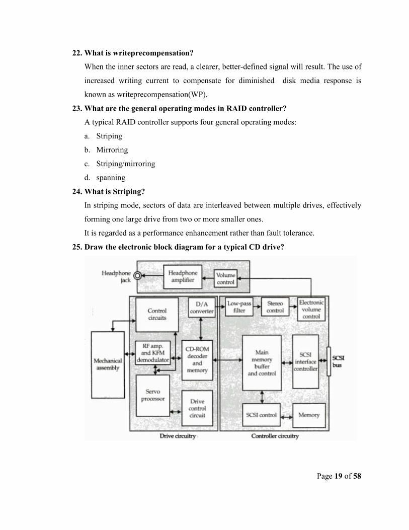
25. Draw the electronic block diagram for a typical CD drive?
Page 20 of 58
PART B
1. Explain the magnetic storage concepts.
• Magnetic media
• Magnetic recording principles
• Data and disk organization
• Floppy drive recording principles
• Media problems
Refer Stephen J-Bigelow-”Troubleshooting-Maintaining & repairing of PCs”
page no: 700
2. Explain the floppy drive interface.
The in assignment for a standard 34 pin floppy drive interface and the physical
interface for data signal and control signals.
refer Stephen J-Bigelow-”Troubleshooting-Maintaining & repairing of PCs” page no:
710
3. Explain the data organization on a hard drive and also the interleave.
• Tracks
• Cylinders
• Sectors
• Diagram for data organization
• Storage capacity
• Sector layout
• Interleave
• Interleave factor
refer Stephen J-Bigelow-”Troubleshooting-Maintaining & repairing of PCs”
page no: 745
4. Discuss the basic hard drive concepts.
• Platters
• Media
• Airflow
• Head flight
Page 21 of 58
• Data density
• Latency and seek
refer Stephen J-Bigelow-”Troubleshooting-Maintaining & repairing of PCs”
page no: 740
5. Discuss Redundant Array of Independent Disks.
• Disk array
• Disk array adapter
• Reserved sector
• Disk array types
• Striping
• Mirroring
• Striping/Mirroring
• Spanning
refer Stephen J-Bigelow-”Troubleshooting-Maintaining & repairing of PCs”
page no: 537
6. Discuss CD standards and characteristics.
• High sierra
• ISO 9660
• CD-ROM Standards
• Digital audio extraction
• Multi-speed drive
• MPC
• MMC
refer Stephen J-Bigelow-”Troubleshooting-Maintaining & repairing of PCs”
page no: 242
Page 22 of 58
UNIT – 4
PC ARCHITECTURE
PART – A
1. What are the elements in a PC hierarchy?
The PC hierarchy has 4 levels :
a. The hardware
b. The BIOS
c. The OS
d. The applications
2. What is BIOS?
A BIOS is a set of small programs (or system services) that are designed to operate
each major PC subsystem (video, disk, keyboard and so on).
Each of these system services is invoked by a set of standard calls (originally
developed by IBM) that are made as needed through the OS.
3. What is the purpose of OS in modern PC?
The first purpose is, an OS interacts with (and provides an extension to ) the BIOS.
This extension provides applications with a rich selection of high level file handling
and disk control functions.
The second purpose is, an OS forms an environment (or shell) through which
applications can be executed and provides a user interface allowing you and your
customers to interact with the PC.
4. How the applications run in a system?
As the application requires system resources during run time, it makes an appropriate
call to the OS or BIOS, which in turn accesses the needed function and returns any
needed information to the calling application.
5. What are the types of BIOS?
• System BIOS
• Video adapter firmware BIOS
• Drive controller firmware BIOS
• Network adapter board BIOS
Page 23 of 58
• Modem card firmware BIOS
• SCSI adapter BIOS
6. What is POST?
The power-on-self test handles virtually all of the initialization activities for a PC
POST performs a low-level diagnostic and reliability test of the main processing
components – including ROM programs and system RAM.
• It tests the CPU,
• initializes the motherboard’s chipset,
• checks the 128 bytes (or more) of CMOS for system configuration data, and
• sets up an index of interrupt vectors for the CPU,
• sets up a BIOS stock, loads BIOS data area in low memory,
• detects any optional equipment in the system and
• proceeds to boot the operating system froman available disk.
7. What is system service routines?
The system services (also referred to as BIOS services) are a set of individual
functions that form the layer between hardware and the operating system.
8. What is hardware interrupts?
The hardware interrupts are generated when a device needs the CPU’s attention to
perform a certain task. Hardware interrupts are invoked by asserting a logic level on a
physical interrupt request line.
9. What is software interrupts?
Software interrupts are generated when a hardware device must be checked or
manipulated by the PC. the “print screen” function is a prime example of a software
interrupt.
10. What are the supports provided by BIOS?
• CPU support
• Chipset support
• Memory support
• Power management support
• Drive support etc
Page 24 of 58
11. What is BOOT versatility support by BIOS?
The BIOS should be able to boot from a number of different drives and include the
BIOS boot specification for Initial Program Load (IPL) devices. This currently
supports booting from up to four IDE- type drives (including CD-ROM), SCSI drives
and network cards.
12. What is I2O support by BIOS?
The BIOS may support I2O (Intelligent I/O) which allows the dynamic assignment of
ports and resources for I/O devices in the PC. This is more commonly found in server
platforms.
13. What is PCI and AGP support?
The BIOS must support Intel’s Peripheral Component Interconnect (PCI) bus
specification, including PCI-to-PCI and PCI-to-ISA bridging. The BIOS must also
support the accelerated graphics port.
14. What is Drive support?
The BIOS must support 32 bit disk transfers and large Ultra- ATA hard drives(over
1024 cylinders) with very fast data transfer modes like Ultra-DMA/33, Ultra-
DMA/66, and Ultra DMA/100.
15. What are the shortcomings in BIOS?
• Flazh laziness
• BIOS shadowing
• BIOS bugs
16. What are the information that help BIOS upgrading?
• PC make and model
• Motherboard manufacturer and CPU
• Make an dversion of existing BIOS
• Part number of the ROM chip itself
• Make, model, and part numbers of main motherboard chipset(s)
17. List some motherboard ports.
• Serial ports
• Parallel ports
Page 25 of 58
• Keyboard ports
• Mouse port
• USB port etc
18. What is front side bus?
The pathway between CPU and RAM is often referred to as front side bus (FSB).
19. What are the system attributes that are controlled by north bridge?
• Processor types that are supported
• Number of processors that are supported
• The maximum amount of memory that is supported
• The type of memory error correction supported
20. What are the features handled by south bridge chip?
• ISA bus support
• One or more USB ports
• An Infrared port
• Power management features
• Keyboard controller
21. List some integrated features in motherboard.
There are four popular integrated features:
• Video adapters
• Sound adapters
• Network adapter
• SCSI adapter
22. What is a device driver?
A device driver is nothing more than a file stored on the PC’s hard drive that contains
all the commands necessary to talk to whatever device it was written to support.
23. What is registry?
Registry is a collection of all the functions of CONFIG.SYS, SYSTEM.INI and a
number of other similar files. Every configuration is stored in the registry, including
all device driver information.
Page 26 of 58
24. What is a device manager?
The device manager is a provision using which the device drivers for any particular
device can be changed or removed.
25. What is post card?
Post card is a device which monitors the POST (Power On Self Test) and identify
which piece of hardware is causing the trouble.
PART B
1. Discuss the American megatrends boot sequence.
• Disable NMI
• Power on delay
• Reset determination
• Detect memory
• Initialize support pins
• Video tests
• Test memory
refer Stephen J-Bigelow-”Troubleshooting-Maintaining & repairing of PCs” page
no: 184
2. Discuss the phoenix technologies.
• Check the CPU
• Test CMOS RAM
• Test PIT
• Test DMA
• Verify video system
• Test CPU cache
• Load the OS
refer Stephen J-Bigelow-”Troubleshooting-Maintaining & repairing of PCs” page
no: 187
3. Explain the shortcomings in BIOS.
• Device drivers
• Flash laziness
Page 27 of 58
• BIOS shadowing
• Direct control BIOS bugs
refer Stephen J-Bigelow-”Troubleshooting-Maintaining & repairing of PCs” page no:
189
4. Discuss the AMD 750 chipset.
• North bridge
• South bridge
• Integrated features
refer Stephen J-Bigelow-”Troubleshooting-Maintaining & repairing of PCs” page
no: 310
5. What are the supports provided by BIOS?
• CPU support
• Chipset support
• Memory support
• Power management support
• Drive support
• PC 99 support
• I2O support
• Boot versatility support
• USB support
refer Stephen J-Bigelow-”Troubleshooting-Maintaining & repairing of PCs” page
no: 156
6. Discuss Device driver.
• Device drivers like CONFIG.SYS
• SYSTEM.INI
• Registry
• Contol panel
• Device manager
• REGEDIT and REGEDT32
Refer Mike Meyers- “Introduction to PC Hardware and Trouble shooting” page no: 159
Page 28 of 58
UNIT – 5
SYSTEM BUS
PART – A
1. What are the information that flows in bus?
• Instruction
• Memory address
• Data
• Register address
• Control signals
• Input/output command
• Input/ output device address
2. What is the use of memory address?
• During an instruction fetch, the contents of the program counter are sent to
the MAR in memory.
• During an operand fetch, the contents of a register in the CPU are sent to the
MAR.
3. What is the use of memory data?
• During an instruction fetch, the contents of the MDR are sent to IR in the
CPU
• During an operand fetch, the contents of the MDR are sent to register in
CPU.
4. How the signals on the bus can be divided?
• Output signals from microprocessor
• Input signals to microprocessor
• Signals both output from and input to microprocessor
5. What is instruction fetch?
• The microprocessor puts an instruction address on the address bus.
• The microprocessor issues a memory read signal on the control bus
Page 29 of 58
• The microprocessor waits for sometime to account for the memory access
time
• The microprocessor now takes the data bus contents and loads it in the
instruction register
6. What is operand fetch?
The sequence is similar to that of the instruction fetch with two differences. In step
1, the memory address is from one of the registers. In step 4, the data bus contents
are loaded into one of the registers.
7. What is operand store?
• The microprocessor puts the memory address from one of the internal
registers onto the address bus.
• The microprocessor puts the data from one of the internal registers onto the
data bus.
• The microprocessor issues a memory write signal on the control bus.
• The memory takes the contents of data bus and stores it in the location whose
address is given in the address bus.
8. What is bus multiplexing?
To reduce the pin count and cost, the data bus and the address bus are usually
multiplexed. In this scheme, instead of dedicating separate pins for the address bus
and data bus, the same pins are used for both the address bus and data bus. At a
given time, either address or data is sent on this multiplexed bus.
9. What are the errors in digital signal transmission?
• The signal is attenuated.
• The transmission line has both distributed inductance and capacitance due to
which the signal is distorted.
10. What is PnP?
PnP (Plug and Play) devices are capable of identifying themselves and their resource
requirements to the rest of the system.
11. List some of the classifications of PnP devices.
• ISA bus cards
Page 30 of 58
• PCI bus cards
• Microchannels architecture
• PC card devices
12. What is detection?
Detection is the process that windows 98/Me uses during its search for legacy (or
non-plug and play) devices on a computer.
13. What is enumeration?
Enumeration is the process that windows 98/ Me uses to identify the PnP devices in
the computer.
14. What is ESCD?
The ESCD is s small amount of nonvolatile RAM (NVRAM) similar to the CMOS
RAM – that holds configuration information for the PnP hardware in your system.
15. What are the features of PCI?
• Data bursting as normal operating mode
• Linear burst ordering
• Low latency
• Error detection
• Concurrency/ pipelining support
16. What is ISA?
The ISA (industry standard architecture) is the first open system bus architecture
used for IBM type personal computers.
It supports the use of standardized operating systems and application software.
17. What is asynchronous configuration in PCI?
In asynchronous configuration of PCI, the speed of a PCI bus can be set
independently of the FSB speed, though this is rare in all but the latest motherboards.
18. What is synchronous configuration in PCI?
In synchronous configuration of PCI, the 33 MHz PCI speed is divided from the
FSB.
Page 31 of 58
19. What are the features of PnP device?
PnP devices are compatible. They are capable of identifying themselves and their
resource requirements to the rest of the system.
20. What is PnP BIOS?
The PnP BIOS is needed to initialize the core PnP devices(such as the video adapter
and boot drive) in order to complete the POST and launch the operating system.
21. What is PnP OS?
The PnP OS takes over where the PnP BIOS leaves off by identifying and
configuring the remaining PnP devices in the system, then loading the appropriate
drivers needed to initialize and operate each respective device.
22. What is the notification of configuration changes in PnP devices?
Each time a PnP device is added or removed from the PC, the PnP system reports the
configuration change. When a device is added, the PnP system attempts to identify it
and install the appropriate device drivers. When a device is removed, the PnP system
attempts to remove all traces of the device and its drivers.
23. What is ESCD?
ESCD (Extended System Configuration Data memory) is a part of the CMOS RAM
space that is used as a central database.
When any resource conflict has been resolved, the operating system automatically
programs each hardware device with its working configuration and then stores all
configuration information in the central database which is contained in ESCD.
24. What is PnP configuration utility?
A PnP utility is loaded in the AUTOEXEC.BAT file. It is the utility that actually
configures and initializes the PnP device.
25. How the legacy devices can be installed?
• In the control panel, double click the Add new hardware icon
• In the Add new hardware wizard, click next, and then select “automatically
detect installed hardware”
• Allow windows 95/98 to detect the new device, and then follow the
instructions to configure the driver.
Page 32 of 58
PART B
1. Discuss bus concept.
• Memory address
• Memory data
• Instruction fetch
• Operand fetch
• Operand store
• Memory read
• Memory write
• I/O read
• I/O write
• Interrupt
• Interrupt acknowledgement
• Reset
Refer B-Govindarajulu- “IBM PC and Clones hardware trouble shooting and
maintenance” page no: 34.
2. Discuss the serial port.
Interface standard
Signal levels
Interface diagram
Components of interconnect
Refer B-Govindarajulu- “IBM PC and Clones hardware trouble shooting and
maintenance” page no:657
3. Discuss the behavior of PnP device.
• Identification of installed devices
• Determination of device resource requirements
• Creation of a complete system configuration, eliminating all resource
conflicts
• Loading of device drivers
• Notification of configuration changes
Page 33 of 58
• Device types and identification
refer Stephen J-Bigelow-”Troubleshooting-Maintaining & repairing of PCs” page no:
1097
4. How the PnP can be enabled under DOS?
• The PnP configuration driver
• The PnP configuration utility
• Blaster variables
• Problems with generic PNP configuration software
• Problems with manufacturer’s PNP software.
• Handling PnP configuration issues under DOS
refer Stephen J-Bigelow-”Troubleshooting-Maintaining & repairing of PCs” page
no: 1108
5. Discuss ISA.
• 8 bit ISA
• XT signals
• 16 bit ISA
• AT signals
• Mixing 8 bit and 16 bit ISA boards
• ISA retirement
refer Stephen J-Bigelow-”Troubleshooting-Maintaining & repairing of PCs”
page no: 220
6. How the PnP devices can be managed?
• Installing PNP devices
• Installing legacy devices
• Updating device drivers
refer Stephen J-Bigelow-”Troubleshooting-Maintaining & repairing of PCs” page no:
1111.
Page 34 of 58
B.E. / B.Tech. DEGREE EXAMINATION, NOVEMBER/ DECEMBER 2007
(Regulation 2004) Electronics and Communication Engineering
EC 1003 – COMPUTER HARDWARE AND INTERFACING
Answer all questions
PART A – (10*2=20)
1. List the performance enhancing features found in a modem processor.
• Scalar architecture
• Pipelining
• Superpipelining
• Speculative execution
• Dynamic execution
2. What is CPU over clocking and what are the failures associated with CPU.
Overclocking is basically the practice of reconfiguring a PC to operate a CPU at a
higher clock speed (or bus speed) than the particular CPU has been specified for.
The higher clock speed should increase the CPU’s performance without damaging the
CPU or reducing its working life.
Trouble in any one of these elements will result in overclocking problems.
e. CPU issues
f. Motherboard issues
g. RAM issues
h. Cooling issues
3. What are the feature that handled as Southbridge chipset.
The South bridge chip can handle the following:
• ISA bus support
• One or more USB ports
• One or more serial (RS232) ports
• A parellel (IEEE 1284) port
• Floppy drive controller
4. List the common entries that are found in the standard CMOS setup menu.
Page 35 of 58
• Boot sequence
• Core speed
• Processor serial number
• Boot virus detection
5. What are the recording techniques used with CD – ROMs and hard disk drives.
The information is sent from the computer processor to the BIOS into a chip controlling
the data transfer.
This is then sent out to the hard drive via a multi-wire connector.
Once the data is received onto the circuit board of the drive, it is translated and
compressed into a format that the individual drive can use to store onto the disk itself.
The data is then passed to a chip on the circuit board that controls the access to the drive.
The drive is divided into sectors of data stored onto one of the sides of one of the internal
disks. An HDD with two disks internally will typically store data on all four surfaces.
6. What is region code control used with DVDs.
DVD region codes are a digital-rights management technique designed to allow film
distributors to control aspects of a release, including content, release date, and price,
according to the region.
DVD video discs may be encoded with a region code restricting the area of the world in
which they can be played.
7. List the features of IEEE 1284 standard for parallel peripheral interface.
The IEEE standard requires the following:
• Support for all five modes of operation.
• A standard method of negotiation for determining which modes are suppported
both by the host PC and by the peripheral device.
• A standard physical interface.
• A standard electrical interface.
8. List the general steps involved in 3D rendering.
Rendering is the process of generating an image from a model (or models in what
collectively could be called a scene file), by means of computer programs.
Page 36 of 58
A scene file contains objects in a strictly defined language or data structure; it would
contain geometry, viewpoint, texture, lighting, and shading information as a description
of the virtual scene.
9. What are the components involved in a plug and play systems.
• ISA bus cards
• PCI bus cards
• Microchannels architecture
• PC card devices
10. What are the signal wiring techniques for SCSI and mention their impact on bus
performance.
There are two different writing techniques for SCSI interfaces. They are known as single-
ended (SE) and differential (DIF). The two techniques are incompatible with each other
and cannot be used together on a same SCSI bus.
PART B – (5*16=80)
11. (a) (i) Discuss the importance features of the Pentium 4 microprocessor.
• Operating parameters
• Network support
• Memory extension
• Speed of operation
(ii) Explain how the CPU, the motherboard, system RAM and CPU cooling influence CPU
over clocking.
The factors that affect the over clocking.
• CPU issues
• Motherboard issues
• System Ram issues
• CPU cooling
(OR)
(b) (i) Explain the different types of memory modules used in the PC.
• SIMM
• DIMM
Page 37 of 58
• RIMM
(ii) Explain the different types of specialized memory devices that have been tailored to
serve specific functions in the PC.
The types of memory are:
n. BEDO (Burst Extended Data Output RAM)
o. CDRAM (Cached DRAM)
p. DDR SDRAM
q. DRAM
r. EDO RAM (Extended Data Out RAM)
s. EDRAM (Enhanced DRAM)
t. FPM DRAM(Fast Page Mode DRAM)
u. RDRAM (Rambus DRAM)
v. SDRAM(Synchronous or Synchronized DRAM)
w. SGRAM(Synchronous Graphics RAM)
x. SRAM
y. VRAM(Video RAM)
z. WRAM(Windows RAM)
12. (a) (i) Show the block diagram of Intel D850GB Pentium 4 motherboard and explain
the function of each block.
• Block diagram
• DMA channels
• I/O controller
• Audio subsystem
• LAN subsystem
(ii) Discuss briefly a typical PC boot process.
• Disable NMI
• Power on delay
• Reset determination
• Detect memory
• Initialize support pins
Page 38 of 58
• Video tests
• Test memory
(OR)
(b) (i) Illustrate an application of a typical chipset.
Explain about the application of chipset in
• PC
• SCSI
• Graphics card
(ii) Describe briefly the core features of BIOS.
• CPU support
• Chipset support
• Memory support
• Power management support
• Drive support
• PC 99 support
• I2O support
• Boot versatility support
• Plug and play support
• Parallel port support
• PCI and AGP support
13. (a) (i) Describe the IDE features and architecture.
• The explorer
• The source editor
• The debugger
• The compiler
• The data file viewer
• The data dictionary
(ii) Discuss the function of different RAID modes.
A typical RAID controller supports four general operating modes:
Page 39 of 58
• Striping
• Mirroring
• Striping/mirroring
• spanning
(OR)
(b) (i) Show a typical hard drive sector layout.
• Diagram
• Write technique
• Layout concept
• Explain about cylinder and sector
• Interleave factor
(ii) Explain the different ways to implement a hard disk servo mechanism.
• Wedge servo
• Dedicated servo
• Embedded servo
(iii) Illustrate the electronic block diagram for a typical CD drive.
• Block diagram
• CD write technique
14. (a) (i) Explain the functions of various parallel port timing diagrams.
• Diagram
Explain the functions of
• Initialize signals
• Data transfer signals
• Error signals
• Select signal
• Busy signal
• Acknowledgement signal
(ii) Discuss the array of features provided in today’s 3D graphics accelerators.
• Bandwidth of 266 MB/s
Page 40 of 58
• AGP 1X
• AGP 4X
• AGP 8X
(OR)
(b) (i) Show the typical parallel port timing diagram.
• Diagram
• Initialize signals
• Data transfer signals
• Error signals
• Select signal
• Busy signal
• Acknowledgement signal
(ii) Explain the function of various serial port signals.
• Tx and Rx
• RTS and CTS
• DTR and DSR
• DCD
• RI
(iii) Show the block diagram of external and internal modem and explain the operation.
• Modem construction and operation
• Internal modem
• Block diagram of an internal modem
• External modem
• Block diagram of an external modem
• X2 technology
15. (a) (i) Explain how the USB trouble shooting can be carried out.
• Hardware failures or configuration problems
• Device driver configuration problems
• Cabling problems
Page 41 of 58
• Firmware/BIOS problems
• Root hub configuration problems
(ii) Explain the function of the signals on a PCI bus.
• CLOCK
• RESET
• GNT
• FRAME
• TRDY
• IRDY
• DEVSEL
• IDSEL
• INTA
• INTD
• REQ64
• ACK64
(OR)
(b) (i) Show the block diagram of the AGP interface and explain the function of each block.
• Diagram
• Functions of each block
• Similarities to PCI
• L2 cache
• Core
• System memory
• Local memory
• Graphics accelerator
(ii) Explain briefly the following1) Plug and Play devices 2) SCSI Concepts.
• Plug and Play concept
• Advantages and application of PnP devices
• SCSI controller
Page 42 of 58
• Advantages and applications of SCSI controller
BE/B.Tech .DEGREE EXAMINATION ,NOVEMBER/DECEMBER 2008.
Seventh Semester(Regulation 2004)
Electronics and Communication Engineering
EC 1003-COMPUTER HARDWARE AND INTERFACING
Answer All Questions
PART-A-(10*2=20 marks)
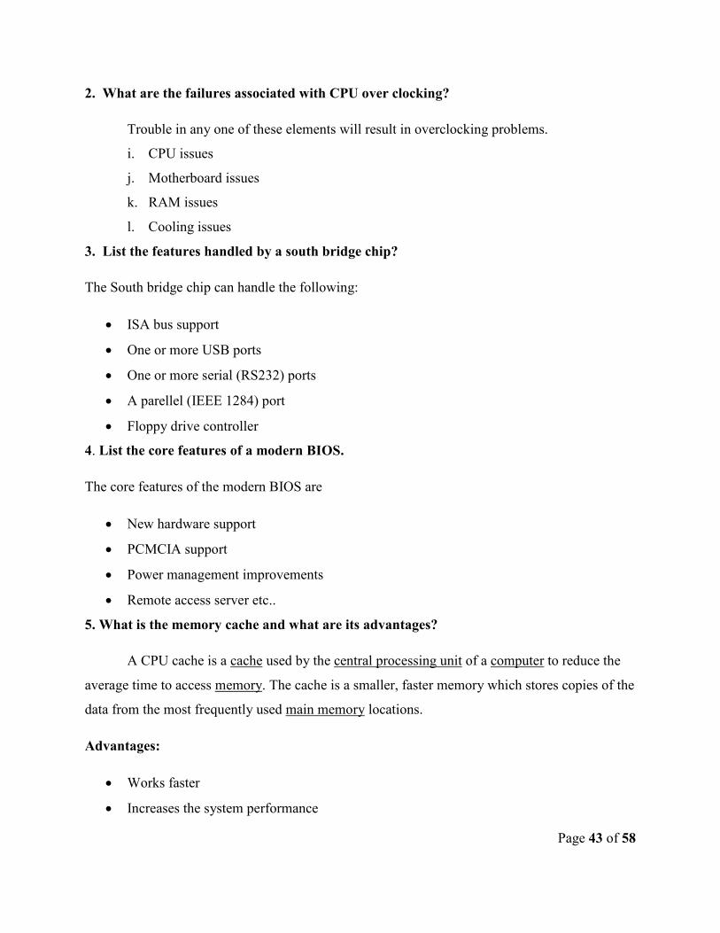
1. Distinguish between CISC and RISC.
CISC RISC
7. CISC stands for Complex Instruction
Set Computing.
7. RISC stands for Reduced Instruction
Set Computing.
8. The compiler is ease of access. 8. The RISC emphasizes compiler
complexity.
9. The CISC emphasizes greater
hardware complexity.
9. The processor is simple to understand.
10. The number of general purpose
register is less when compared to
RISC.
10. The RISC processors have large
number of general purpose registers.
11. Pipelining implementation is not
easy.
11. Pipelining can be implemented easily.
12. Large amount of different and
complex instructions.
12. Fewer, simpler and faster instructions.
Page 43 of 58
2. What are the failures associated with CPU over clocking?
Trouble in any one of these elements will result in overclocking problems.
i. CPU issues
j. Motherboard issues
k. RAM issues
l. Cooling issues
3. List the features handled by a south bridge chip?
The South bridge chip can handle the following:
• ISA bus support
• One or more USB ports
• One or more serial (RS232) ports
• A parellel (IEEE 1284) port
• Floppy drive controller
4. List the core features of a modern BIOS.
The core features of the modern BIOS are
• New hardware support
• PCMCIA support
• Power management improvements
• Remote access server etc..
5. What is the memory cache and what are its advantages?
A CPU cache is a cache used by the central processing unit of a computer to reduce the
average time to access memory. The cache is a smaller, faster memory which stores copies of the
data from the most frequently used main memory locations.
Advantages:
• Works faster
• Increases the system performance
Page 44 of 58
6. What are zonal recording and write compensation techniques employed in hard drives?
Write precompensation (abbreviated WPcom in the literature) is a technical aspect of
hard disk design. It is the use of a stronger magnetic field to write data in sectors that are closer
to the center of the disk. In constant angular velocity recording, in which the disk spins at a
constant speed no matter where the data is written, the sectors closest to the spindle are packed
tighter than the outer sectors and so require a stronger magnetic field to write the data.
13. List the features of IEEE 1284 mode for the parallel port.
The IEEE standard have the features of the following:
• Support for all five modes of operation.
• A standard method of negotiation for determining which modes are suppported
both by the host PC and by the peripheral device.
• A standard physical interface.
• A standard electrical interface.
14. List the features of Direct X.
• Includes DirectXMath,
• XAudio2,
• and XInput libraries from the XNA framework.
• It also features stereoscopic 3D support for gaming and video
15. What are the three components involved in PnP system?
• The three components involved in a PnP system : PnP devices
• PnP BIOS
• PnP compliant operating system
10. List the different phases of operation involved in the SCSI communication.
The different phases of operation involved in the SCSI communication are:
• Bus free
• Arbitration
• Selection
Page 45 of 58
• Command
• Reselection
• Data
• Message
• status
PART-B-(5*16=80)
11. a) (i) Describe the performance enhancement features found in modern
microprocessors.
• Superscalar architecture
• Pipelining
• Super pipelining
• Dynamic execution
• Speculative execution
• Branch prediction
• Multimedia extension
(ii) Explain the critical elements of any PC that influence over clocking.
• CPU issues
• Motherboard issues
• System RAM issues
• Cooling issues
(or)
b) (i) Discuss the different modes of operation that have evolved for a PC.
• Real mode
• Protected mode
• Virtual real mode
(ii) Discuss the salient features of different memory types.
Page 46 of 58
Features of
• ROM
• RAM
• SRAM
• DRAM
• SDRAM
• Integrated RAM
12. a) (i) Show the block diagram of a typical chipset and explain the functions performed
by North bridge chip.
• Processor types that are supported
• Number of processors that are supported
• The maximum amount of memory that is supported
• The type of memory error correction supported
(ii) Explain the BIOS shortcomings and compatibility issues.
• Device drivers
• Flash laziness
• BIOS shadowing
• Direct control BIOS bugs
refer Stephen J-Bigelow-”Troubleshooting-Maintaining & repairing of PCs” page no: 189
(or)
b) (i) Explain the boot process.
• Applying power
• The bootstrap
• Core tests
• POST
• Finding the OS
• Loading the OS
Page 47 of 58
(ii) Show the block diagram of a typical Pentium 4 motherboard and explain the function
of various blocks.
• Block diagram
• Specifications
• Motherboard support
• Overclocking support
• RAM extension
• Chipset support
• Graphical support
13. a) (i) Discuss the use of hard drive cache and explain the current enhancements
implemented in the cache management circuitry.
• Type of cache
• Construction
• Working and accessing techniques
• Implementation
• improvements
(ii) Explain the block diagram of a typical hard drive electronics system.
• Diagram
• Drive concepts
• Write precompensation
• Zonal recording
(or)
b) (i) Explain the block diagram of a typical CD drive.
• Diagram
• Drive concepts
Page 48 of 58
• CD access technique
• Recordable CD
(ii) Explain IDE drive standard and its features.
• Diagram
• Working principle
• Drive electronics
14. a) (i) Show the parallel port timing diagram and describe the standard sequence of
events in a parallel port.
• Port operation
• Timing diagram
• Advanced parallel port operation
• Unidirectional ports
• Types of bidirectional port
• IEEE1284 modes
(ii) Explain briefly the audio benchmarks.
• Standards of sound boards
• Accelerated Graphics Port (AGP)
(or )
b) (i) Discuss briefly the various features offered by the 3D graphics accelerators.
• Motion compensation
• Intra frame prediction
• Variable length decoding
(ii) Explain the function of various signals on serial port.
• DTE
• DCE
• Transmitted data
• Received data
Page 49 of 58
• Data terminal ready
• Carrier detect
• Common ground etc..
15. a) (i) Discuss briefly the features of current PCI bus and explain the function of
various signals on a PC bus.
• Features of PCI
• Configuration and signals
• Arbitration support
• CMOS drivers
• TTL voltage levels
(ii) Discuss the characteristics of USB
• USB devices
• Pin configuration
• Enabling USB
• HOST controller
• Supported controllers
• USB 2.0
(or )
b) (i) List the major differences between PCI and AGP and explain the block diagram of an
AGP interface.
• Features of both PCI and AGP
• Configuration and signals of both PCI and AGP
• Block diagram of AGP
• Layout of PCI bus
(ii) Describe the requirements for PnP and outline the special requirement for
implementing PnP under DOS?
Page 50 of 58
• Identification of installed devices
• Device types and identification
• Enabling PnP under DOS
• Configuration drivers
ANNA UNIVERSITY OF TECHNOLOGY, COIMBATORE
B.E.,/B.TECH. DEGREE EXAMINATIONS: NOV/DEC 2011
Answer all questions
PART A
1. What is meant by ISR?
For a successful I/O completion interrupt, use of the data received from the input device
can be started. In the case of output device another I/O operation can be initiated. For an
interrupt due to unsuccessful I/O completion, the previous I/O operation can be retried.
All these actions can be retrieved by programs. These programs are known as Interrupt
Service Routine(ISR).
2. What are the types of OS?Give one example for each type.
• The Operating System may be of 6 types:
• Batch OS
• Interactive OS
• Time-sharing OS
• Multitasking/Multiprogramming OS
• Real-time OS
• Multiprocessor OS
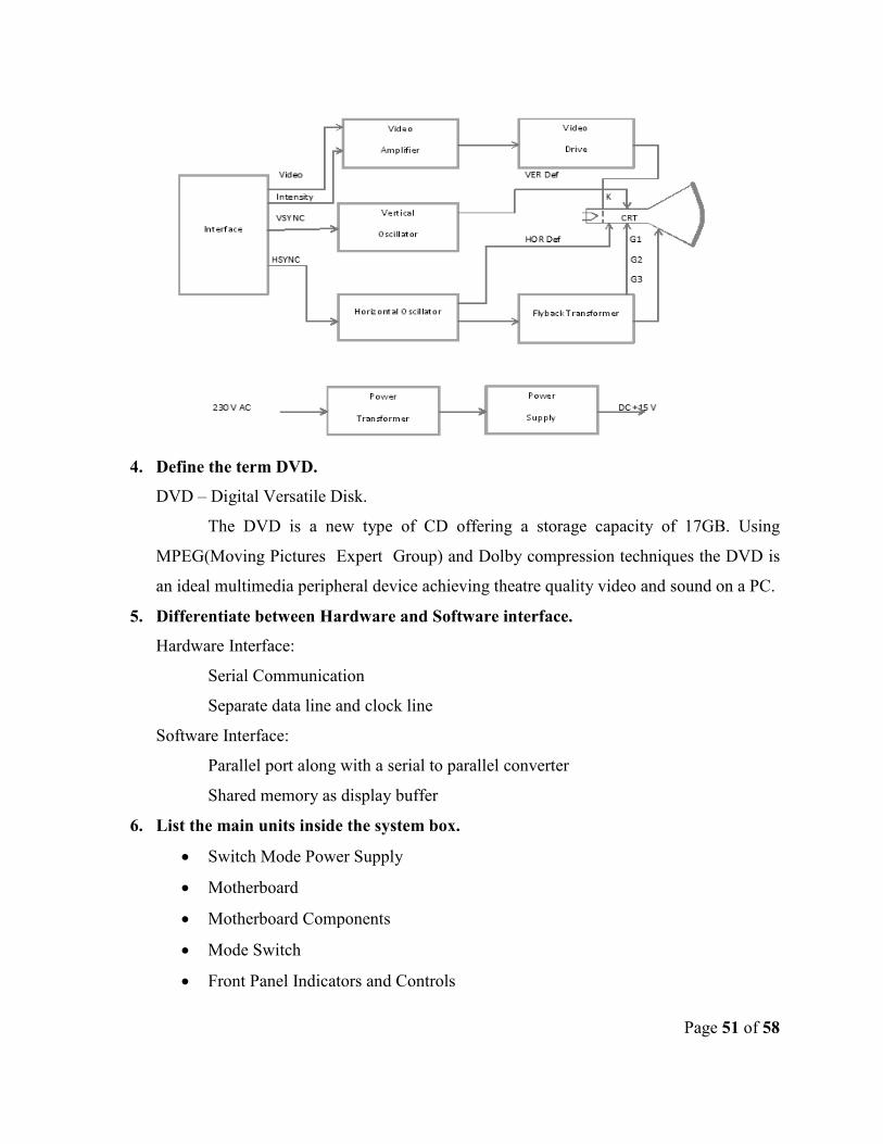
3. Draw the block diagram for CRT Display monitor.
Page 51 of 58
4. Define the term DVD.
DVD – Digital Versatile Disk.
The DVD is a new type of CD offering a storage capacity of 17GB. Using
MPEG(Moving Pictures Expert Group) and Dolby compression techniques the DVD is
an ideal multimedia peripheral device achieving theatre quality video and sound on a PC.
5. Differentiate between Hardware and Software interface.
Hardware Interface:
Serial Communication
Separate data line and clock line
Software Interface:
Parallel port along with a serial to parallel converter
Shared memory as display buffer
6. List the main units inside the system box.
• Switch Mode Power Supply
• Motherboard
• Motherboard Components
• Mode Switch
• Front Panel Indicators and Controls
Page 52 of 58
• Speakers
• EPROM/ROM Types Floppy Disk Drives
• Hard Disk Drives
7. What is preventive maintenance?
The PC is a machine with electrical and electronic circuits as well as electromechanical
assemblies. For reliable operation and long life, the PC should be handled carefully. The
computer should be operated gently without applying force. The computer room must be
clean and Dust free.
8. What are the steps to be taken on finding a Virus?
1) Switch off the computer system to ensure that the virus in the memory does not
spread anymore.
2) Confirm if the problem is actually because of the virus. It could be a hardware or
other software related problem.
3) Boot from a clean write-protected floppy diskette.
4) Check your system for extent of infection and repair or delete all the infected files.
5) Check and remove the virus the virus from every floppy that was used in the system.
9. How can we classify faults?Why do we need such classifications?
Solid fault: When there is a permanent fault in a computer, the computer behaves
consistently. Any number of times the program is run, the result or symptoms will be the
same.
Intermittent fault: When there is an intermittent fault in a computer, the computer’s
behavior is not consistent. Sometimes it works properly and suddenly it malfunctions.
After a certain period of time, it recovers from the fault automatically again atarts
functioning properly.
10. List the steps involved in systematic troubleshooting.
Systematic troubleshooting is the most powerful tool in the hands of an engineer. It is a
scientific and analytical process. The systematic troubleshooting approach can be
divided into the following steps:
1. Symptoms observation
2. Symptoms analysis
Page 53 of 58
3. Fault diagnosis’
4. Fault rectification
PART B
11. (a) Explain in detail about the control unit(CU) with neat block diagram.(16)
• Hardware Resources
• Control Unit block diagram
• Flags:
• Interrupt Enable
• Overflow
• Hardwired and microprogrammed Control Unit
• Block diagram of Microprogrammed control unit
(Or)
(b)Discuss about the following.
(i) Virtual memory
• Program folding
• Page fault
• Diagram – Virtual memory concept
• Advantages of virtual memory
• Logical address and physical address
• Virtual memory mechanism
(ii)Cache memory
• Diagram – Cache Memory
• Page replacement
• Hit/Miss ratio
• Write-through or Write-back policy
12. a) Describe about the printer and its type in detail.
• Diagram – Printer Block Diagram
• Printer Characteristic
• Printer types
Page 54 of 58
• Impact and Non-impact printer
• Character printer and Line printer
• Draft, LQP and NLQ printer
• Parallel Interface and serial Interface
• Unidirectional and Bidirectional printers
• Daisy Wheel printer
• Dot Matrix printer
• Golf Ball printer
• Thermal printer
• Laser printer
• LED printer
• Ink Jet printer
(Or)
b) Explain in detail about the HDD and its type.
• Removable Disk Drive and Fixed Disk Drive
• Moving Head and Fixed Head Disk Drive
• Single Head Assembly and Dual Head Assembly
• Winchester and Non-Winchester Disk Drive
• Open-Loop and Closed- Loop Disk Drive
• Diagram - Closed-Loop Positioning System
• Size and Capacity
• Hard Disk Drive Organisation
• Data Organisation on Hard Disk
13. a) Explain in detail about the PC family and PC hardware with neat functional
diagram.
• PC Family – OG:
o Difference between a PC-AT , PC and PC-XT
o PC family
Page 55 of 58
o IBM PC and Clones
o PC/AT Major new features
• PC Family – NG :
o Additional Features in Clones
• PC Hardware – OG:
o Diagram
� Block Diagram of a PC System
� Functional Block Diagram of a PC
� 8088 Microprocessor
o CPU
o Peripherals
• PC Hardware – NG
(Or)
b) Draw the block diagram for motherboard logic and explain in detail.
• Diagram – Motherboard Logic
• Reset Logic
o Diagram - Reset Logic
• Keyboard Interface
o Diagram - Keyboard Interface
• Interrupt Logic
o Diagram - Interrupt Logic
• RAM Parity Logic
o Diagram - RAM Parity Logic
• NMI Logic
o Diagram - NMI Logic
• Memory Refresh Logic
o Diagram – DMA Refresh Logic
• Wait State Logic
Page 56 of 58
o Diagram – Wait State Logic
• Bus Arbitration Logic
o Diagram – Bus Arbitration Logic
• RAM Logic
o Diagram - RAM Logic
• CPU Logic
o Diagram - CPU Logic
• DMA Logic
o Diagram - DMA Logic
• New generation Motherboard logic
14. a) Explain in detail about the PC assembling and Integration.
• System box preparation
• Motherboard stuffing
• Motherboard Installation
• IDE Drives Preparation
• Drive Installation
• Daughterboard’s Installation
• Cables Connection
• Power Connection
• BLOS setup
• Loading Software
(Or)
b) Discuss about the DOS and how it gets control with activation sequence.
• Anatomy of DOS
• IO.SYS
• MSDOS.SYS
• COMMAND.COM
• DOS : The Command Processor
o Internal Commands
o External Commands
Page 57 of 58
• Sample External Commands of DOS
o Special files
• How DOS gets Control
• DOS : The Resource Manager
• Standard Formats
o Floppy Diskette: Physical Organisation
o Logical Organisaion of the disk space
� Files area
� System area
� Boot record
� File allocation table
� Root directory
15. a) Explain in detail about the multidimentional view to be applied in fault diagnosis.
• Fault diagnosis:
o Architecture
o Organisation
o Engineering layout
o Environment
(Or)
b) Explain in detail about the fault elimination process.
• Common fault elimination steps
• Dead system
• Spurious problems
• Security failures
• Heart beats:
• Keyboard Flash
• Memory Refresh Request
• Timer 0-Ticks
• Multiple Faults:
• Voltage Spikes

Page 58 of 58
• Short Circuit
• Defective Power Supply
• Wrong Operation


![Cognitive Predictors of a Common Multitasking Ability ...mjkane/pubs/Redick et al 2016, JEPG [multitasking].pdfCognitive Predictors of a Common Multitasking Ability: Contributions](https://img.pdfslide.net/doc/110x75/5af43c547f8b9a74448c98a4/cognitive-predictors-of-a-common-multitasking-ability-mjkanepubsredick-et.jpg)