Embed Size (px)
Citation preview

UNIT-V
GAS TURBINES & AIR COMPRESSORS
1. What is Gas Turbine and write its classifications?
A gas turbine is similar to the steam turbine but hot gas is used to run the turbine. It is mainly
used in the aircraft engines, electric power generation, marine propulsion etc.
Classification of gas turbines
1. According to the cycle of operation
a) Open cycle gas turbines
b) Closed cycle gas turbines and
c) Semi closed cycle gas turbines
2. According to the process
a) Constant pressure gas turbines and
b) Constant volume gas turbines
3. According to the use
a) Industrial gas turbines and
b) Air craft gas turbines
2. Explain main components and working of gas turbine?
MAIN COMPONENTS OF GAS TURBINES A gas turbine unit consists of the following essential parts:
(a) Compressor: The air compressor used in gas turbines is of rotary type mainly axial
flow turbines. It draws air from the atmosphere and compressed to the required pressure. This
compressed air is then transferred of the air instantaneously.
(b) Combustion chamber: The compressed air from the air compressor is drawn to
combustion chamber. The fuel is injected to the air and then ignited in the combustion chamber.
It increased the pressure and temperature of the air instantaneously.
(c) Turbine: The high pressure and temperature air is expanded in the turbine. Turbine is
also of rotary type. During the expansion, the heat energy in the gas is converted into mechanical
energy. This mechanical energy is again converted in to electrical energy by using generator
WORKING OF OPEN CYCLE GAS TURBINE
The most basic gas turbine unit is one operating on the open cycle in which a rotary
compressor and a turbine are mounted on a common shaft as shown in fig
Air is drawn from the atmosphere into the compressor and compressed to pressure of 300 to
400 kN/m. The compressed air is then entered into the combustion chamber where the energy supplied
by spraying fuel into the air and is ignited by hot gases. The hot gases expand through the

turbine to produce the mechanical power. And then the burned gases are exhausted to the atmosphere.
Then fresh air is drawn into the compressor for next cycle. The process is repeated again and again.
Here, the compressor is driven by turbine itself. In order to achieve the network output from the unit,
the turbine must develop more gross work output than the work required to drive the compressor and
to overcome mechanical losses in the drive.
Open cycle gas turbine
Working of closed cycle gas turbines
It consists of a compressor, combustion chamber, gas turbine and precooler. The schematic
diagram of a closed cycle gas turbine plant is shown in fig.
In a closed cycle gas turbine, the air is compressed in air compressor isentropic ally to a
required pressure and then passed through a combustion chamber where fuel injects to the air and
ignited. The high temperature air from combustion chamber expands through a gas turbine where the
heat energy is converted into mechanical energy. Then the exhaust gas from the gas turbine is passed
through a pre – cooler where it is cooled at constant pressure with the help of circulating water to its
original pressure. Then the same air is passed through the compressor again and again.
It is thus obvious, in a closed cycle gas turbine; the same air is continuously circulated
repeatedly throughout the system.

3. Differentiate between closed and open cycle.
COMPARISON OF OPEN AND CLOSED CYCLE GAS TURBINES
Sl. No. Open Cycle gas turbine Closed Cycle gas turbine
Advantages Disadvantages
No pre-cooler is required because Separate pre-cooler arrangement is
1.
of burned gas from gas turbine exhausted
necessary
to atmosphere
For the same power developed, the
2. size and weight of the open cycle gas The size and weight is more.
turbine unit is less
3. Initial cost and maintenance cost of
Initial cost and maintenance cost is more. the plant is less.
4. Combustion efficiency is more. Combustion efficiency is less.
Coolant is not required therefore it Coolant is required for pre-cooler
5. is used for moving vehicle such as air craft, therefore it is used for stationary applications
jet propulsion etc. such as power generation etc.
6. The response to load variation is
The response to load variation is less. greater than closed cycle gas turbine.
S. No. Disadvantages Advantages
Part load efficiency decreases rapidly
1.
as the considerable percentage of power Efficiency is same throughout
developed by the turbine is used drive the
the cycle.
compressor.
Turbine blades are fouled by the
The turbines blades do not
2.
wear away, since the combustion is
combustion products.
external
3. Starting of the plant is difficult. Starting of the plant is easy.
4.
As direct heating is used in open cycle Low quality fuels can be used
plant, high quality fuels are required.
since the combustion is external.
5. Thermal stresses are high Thermal stresses are low.
6.
Frequent internal cleaning of the No need for internal cleaning.
system is necessary

4. Derive the Efficiency and Work ratio of Gas Turbine.
BRAYTON CYCLE OR JOULE CYCLE
The Brayton cycle is the theoretical cycle for gas turbines. It consists of two reversible
adiabatic processes and two constant pressure processes. This cycle is, therefore, also called constant
pressure cycle. The p-V and T-s diagram for this cycle is shown in fig
Process 1-2
Isobaric Ignition: Fuel mixed with the high pressure air and burned at constant pressure.
Heat added, QS = m CP [T2 – T1]
Process 2-3
Adiabatic Expansion: Hot gases expand in the turbine stages.
Turbine Work, WT = m CP [T2 – T3]
Process 3-4
Isobaric Exhaust: Constant pressure ejection of the spent, hot gases to the environment
Heat Rejected, QR = m CP [T3 – T4]
Process 4 -1
Adiabatic Compression: Air drawn into the compressor and compressed in the compressor stage
Compressor Work, WC = m CP [T1 – T4]
Thermal Efficiency:
–
–
–
– – - - - - - - - (1)
–
We know that pressure ratio
r =
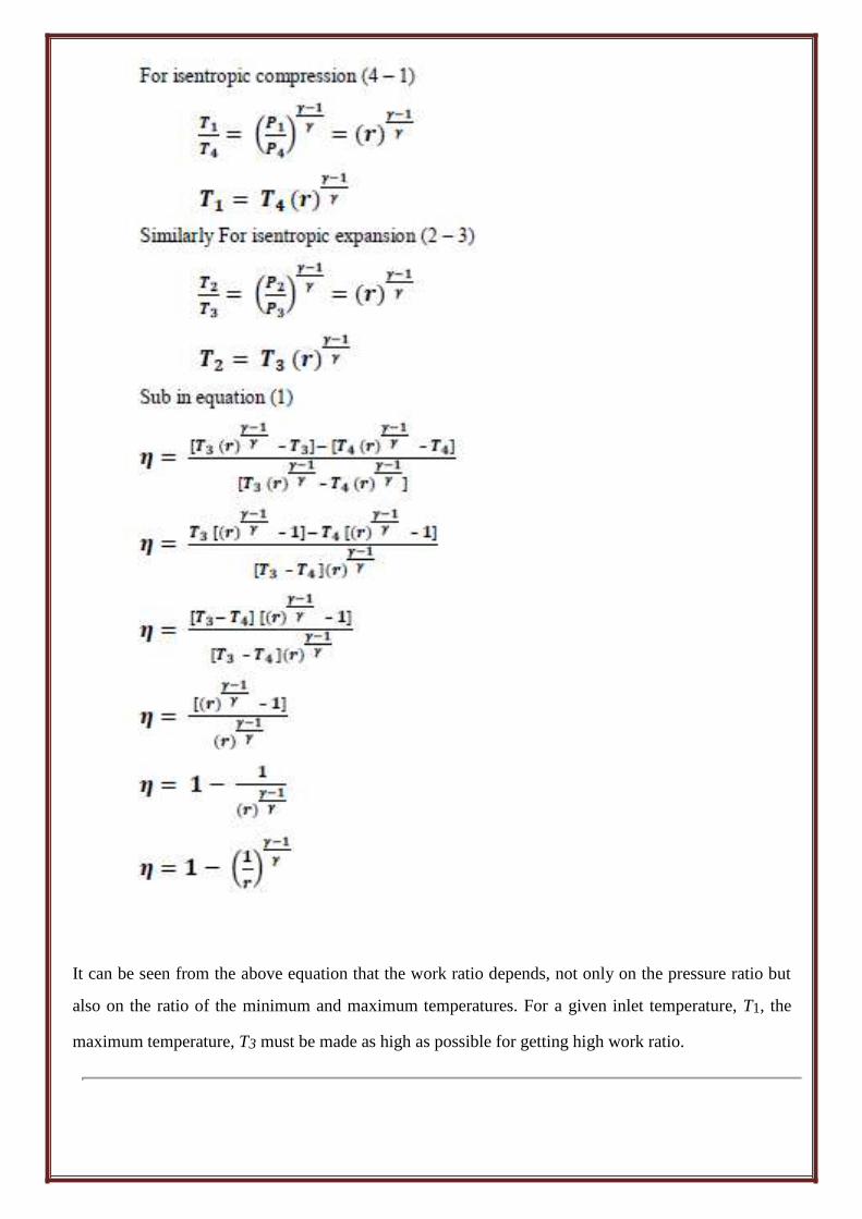
For isentropic compression (4 – 1) ( )
Similarly For isentropic expansion (2 – 3) ( )
Sub in equation (1) – –
– – – –
– –
–
( )
It can be seen from the above equation that the work ratio depends, not only on the pressure ratio but
also on the ratio of the minimum and maximum temperatures. For a given inlet temperature, T1, the
maximum temperature, T3 must be made as high as possible for getting high work ratio.

5. Explain how heat is recovery from exhaust gas of the Gas turbine?
The temperature of exhaust gases of the turbine is higher than the temperature of the air after
compression. If the heat energy is used to heat the air after compression in the heat exchanger called
“regeneration”. It will reduce the energy requirement from the fuel thereby increasing the efficiency
of the cycle. Fig. a) shows the single stage regenerative gas turbine cycle and Fig. b) is the
Corresponding cycle represented on T – s diagram
Thermal Efficiency:
Work of the turbine : WT = m CP [T4 – T6]
Work of the compressor : WC = m CP [T3 – T1]
Heat Supplied : QS = m Cp [T4 – T3]
– –
–
– –
–
– –
– –
- - - - - - - (1) –
For ideal cycle T5 = T3, T6 = T2
- - - - - - - (2)
–
For constant pressure heat exchangers
P2 = P3 = P4, P1 = P5 = P6

For isentropic compression (2 – 1) ( )
( )
Similarly For isentropic expansion (5 – 4) ( )
( ) = ( ) (P2 = P3 = P4, P1 = P5 = P6)
Sub in equation (2)
( )
– (
)
[ (
)
]
[
– (
)
]
[ ( )
( )
]
( )
[ ( )
– ( )
]
( )
(
)
From the above formula, it is obvious that the efficiency of the regenerative Bray ton cycle
depends not only on the pressure ratio but also on the ratio of the two extreme temperature.

6. Explain the effect of reheat and intercooling in gas turbine power
plant? Gas turbine with intercooling:
Major portion of the power produced from the turbine is utilized by compressor. It can be
reduced by compressing the air in two stages with an intercooler between the two. This improves
the efficiency of the gas turbine.
Working:
The air is compressed in the first compressor known as low pressure compressor and results the
pressure and temperature of the air is increased.
Now the air is passed to an intercooler which reduces the temperature to its original, but keeping
the air at constant pressure.
The compressed air is again compressed in the second compressor known as high pressure
compressor.
Now the compressed air is passed through the heating chamber and then through the turbine.
Finally air is cooled in the cooling chamber and again passed into the low pressure compressor
T-s Diagram of intercooling:
Process of intercooling:
Process 1-2
Isobaric Ignition: Fuel mixed with
the high pressure air and burned at constant
pressure.
Heat added, QS = m CP [T2 – T1]
Process 2-3
Adiabatic Expansion: Hot gases
expand in the turbine stages.
Turbine Work, WT = m CP [T2 – T3]
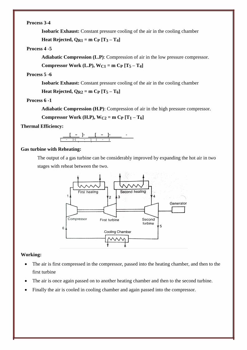
Process 3-4
Isobaric Exhaust: Constant pressure cooling of the air in the cooling chamber
Heat Rejected, QR1 = m CP [T3 – T4]
Process 4 -5
Adiabatic Compression (L.P): Compression of air in the low pressure compressor.
Compressor Work (L.P), WC1 = m CP [T5 – T4]
Process 5 -6
Isobaric Exhaust: Constant pressure cooling of the air in the cooling chamber
Heat Rejected, QR2 = m CP [T5 – T6]
Process 6 -1
Adiabatic Compression (H.P): Compression of air in the high pressure compressor.
Compressor Work (H.P), WC2 = m CP [T1 – T6]
Thermal Efficiency:
[ – ]- [ – ]- - –
[ – ] - [ – ] [ – ] [ – ]
Gas turbine with Reheating:
The output of a gas turbine can be considerably improved by expanding the hot air in two
stages with reheat between the two.
Working:
The air is first compressed in the compressor, passed into the heating chamber, and then to the
first turbine The air is once again passed on to another heating chamber and then to the second turbine.
Finally the air is cooled in cooling chamber and again passed into the compressor.

T-s diagram of reheating:
Process of reheating:
Process 1-2
Isobaric Ignition: Fuel mixed with air and burned at constant pressure in first turbine.
Heat added, QS1 = m CP [T2 – T1]
Process 2-3
Adiabatic Expansion: Hot gases expand in the first turbine
Turbine Work, WT1 = m CP [T2 – T3]
Process 3-4
Isobaric Ignition: The air is once again passed on to another heating chamber
Heat added, QS2 = m CP [T4 – T3]
Process 4 -5
Adiabatic Expansion: Hot gases expand in the second turbine
Turbine Work, WT2 = m CP [T4 – T5]
Process 5 -6
Isobaric Exhaust: Constant pressure cooling of the air in the cooling chamber
Heat Rejected, QR = m CP [T5 – T6]
Process 6 -1
Adiabatic Compression: Compression of air in the compressor.
Compressor Work, WC = m CP [T1 – T6]
Thermal Efficiency:
[ – ] [ – ]- -
– –
[ – ] [ – ] - -
– –

7. Explain classification of reciprocating air compressor and working of single stage
reciprocating air compressor? Air compressors may be classified as follows: 1) According to design and principle of operation
a) Reciprocating compressors b) Rotary compressors
2) According to action a) Single acting compressors b) Double acting compressors
3) According to number of stages a) Single stage compressors b) Multistage compressors
4) According to pressure limit a) Low pressure compressor b) Medium pressure compressors c) High pressure compressors
5) According to capacity
a) Low capacity compressors (Volume delivered 0.12m3/s or less)
b) Medium capacity compressors (volume delivered 0.15m3/s to 5m
3/s )
c) High capacity compressors (Volume delivered is above 5m3/s)
Single stage compressor:
In single stage compressor, the compression of the air from the initial pressure to the
final pressure is carried out in one cylinder only.
Multistage compressor:
In multistage compressor, the compression of the air from the initial pressure to the
final pressure is carried out in more than one cylinder.
WORKING OF SINGLE STAGE RECIPROCATING AIR COMPRESSOR
Single stage reciprocating air compressor
In a single stage compressor, the
compression of air from the initial pressure to
final pressure is carried out in one cylinder
only. A schematic diagram of single stage,
single acting compressor is shown in fig
It consists of a cylinder, piston,
connecting rod, crank, and inlet and discharge
valves. When the piston moves downward i.e.
during suction stroke, the pressure of air inside
the cylinder falls below the atmospheric
pressure. So the inlet valve opens and the air
from atmospheric is sucked into the cylinder
until the piston reaches the bottom dead center.
During this stroke delivery valve remains
closed. When the piston moves upwards both
valves are closed. So the pressure inside the
cylinder goes on increasing till it reaches
required discharge pressure. At this stage, the
discharge value opens and the compressed air is
delivered through this valve. Thus the cycle is
repeated.

8. Find the work done by a single stage reciprocating air compressor without clearance
volume?
a) Work done isothermal compression ( pv = c):
The p-v diagram for a single stage single acting reciprocating air compressor is show is fig. the
sequences of operation as represented on the diagram are as follows:
Isothermal compression
Process 4-1 => Represents the suction of air at pressure p1
Process 1-2 => Air is compressed isothermally from pressure p1 to pressure
p2 Process 2-3 => represents the discharge of air at pressure p2
Work done = Area 1 – 2 – 3 – 4 – 1
W = Wcomp + WDelivery – WSuction
For Isothermal process
W (comp) = p1 v1
WDelivery = p2v2
WSuction = p1v1
p1v1 = p2v2
W = p1 v1
+ p2v2 - p1 v1
W = p1 v1
+ p2 v2 – p2 v2
W = p1 v1
*
+
W = p1 v1
b) Work done during polytrophic compression (pvn = constant);
The p-v diagram for a single stage single acting reciprocating air compressor is shown in fig.
The sequences of operations as represented on the diagram are as follows:
Process 4-1 => Represents the suction of air at pressure p1
Process 1-2 => Air is compressed Polytropically from pressure p1 to pressure
p2 Process 2-3 => Represents the discharge of air at pressure p2

Polytropic compression
Work done = Area 1 – 2 – 3 – 4 – 1
W = Wcomp + WDelivery – WSuction
For Polytropic process
W (comp) =
WDelivery = p2v2
WSuction = p1v1
p1 = p2
W =
+ p2v2 - p1 v1
W =
W =
W=
=
*
+
W =
W = [(
) ]
where, (
)
c) Work done during isentropic compression (or) adiabatic compression [pv = C]:
The p-v diagram for a single stage single acting reciprocating air compressor is shown in fig.
Adiabatic compression
The sequences of operation as represented on the diagram are as follows:
Process 4-1 => Represents the suction of air at pressure p1
Process 1-2 => Air is compressed adiabatically from pressure p1 to pressure
p2 Process 2-3 => Represents the discharge of air at pressure p2
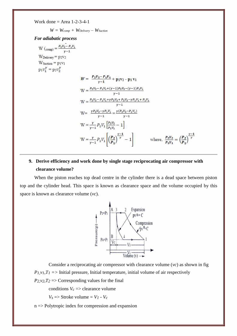
Work done = Area 1-2-3-4-1
W = Wcomp + WDelivery – WSuction
For adiabatic process
W (comp) =
WDelivery = p2v2
WSuction = p 1v1
p1 = p2
W =
+ p2v2 - p1 v1
W =
W =
W=
=
*
+
W =
W = [(
) ]
where, (
)
9. Derive efficiency and work done by single stage reciprocating air compressor with
clearance volume?
When the piston reaches top dead centre in the cylinder there is a dead space between piston
top and the cylinder head. This space is known as clearance space and the volume occupied by this
space is known as clearance volume (vc).
Consider a reciprocating air compressor with clearance volume (vc) as shown in fig
P1,v1,T1 => Initial pressure, Initial temperature, initial volume of air respectively
P2,v2,T2 => Corresponding values for the final
conditions Vc => clearance volume
Vs => Stroke volume = V1 - Vc
n => Polytropic index for compression and expansion

Work done by the compressor per cycle
W = Area 1-2-3-4-1 = (Area 1-2-A-B-1) – (Area 3-A-B-4-3)
Where, Va =V1 – V4 is the actual volume of free air delivered per
cycle VOLUMETRIC EFFICIENCY
Volumetric efficiency is defined as the ratio of volume of free air sucked into the compressor
per cycle to the stoke volume of the cylinder.
vol =
vol =Va/Vs
10. Explain the influence of intercooling on the cycle efficiency in multistage reciprocating
air compressor? MULTISTAGE COMPRESSION:
Multi staging is simply the compression of air or gas in two or more cylinders in place of a single
cylinder compressor. It is used in reciprocating compressors when pressure of 300 KPa and above is
desired, in order to:
1) Save power
2) Limit the gas discharge temperature
3) Limit the pressure differential per cylinder
4) Prevent vaporization of lubricating oil and to prevent its ignition if the temp becomes too high.
It is a common practice for multi-staging to cool the air or gas between stages of compression in an
intercooler, and it is this cooling that affects considerable saving in power Two stage reciprocating air compressor with intercooler:
For an ideal multistage compressor, with perfect inter-cooling and minimum work, the cylinder
was properly designed so that:
a) the work at each stage are equal
b) the air in the intercooler is cooled back to the initial temperature
c) no pressure drop occurs in the intercooler

Working:
Fresh air is sucked from the atmosphere in the low pressure cylinder during its suction
stroke at intake pressure p1 and temperature T1
The air after compression in the L.P cylinder from 1 to 2 is delivered to the intercooler
at pressure p2 and temperature T2
Now the air is cooled in the intercooler from2 to 3 at constant pressure P2 and from
temperature T2 to T3.
After that the air is sucked in the high pressure cylinder during its suction stroke
Finally the air after further compression in the H.P cylinder from 3 to 4 is delivered by
the compressor at pressure p3 and temperature T4.
If the T1 = T3 then it is called perfect intercooling, if T1 ≠ T3 then it is called
imperfect intercooling.
11. Explain a) Centrifugal compressors b) Vane blower c) Roots blower a) Centrifugal compressors
In this type of compressor air enters axially and leaves radially.
Construction: The arrangement of centrifugal compressor is shown in Fig.
It consists of a rotating impeller, a casing and a diffuser.
The impeller consists of a disc on which radial blades are attached. The impeller is surrounded by casing.
The diffuser is other important part of the compressor, which is used to convert kinetic energy of air into pressure energy.
The air coming out from the diffuser is collected in the casing and taken out from the outlet of the compressor.
The impeller of a centrifugal compressor can be run at speeds of 20,000 to 30,000rpm

Centrifugal compressor
Working: When the power is given to compressor, the impellor, the impeller rotates, and it sucks the air.
This air enters axially with low velocity. The velocity and pressure of the air passing through the impeller are partially increased.
Then the air is entered into diffuser. In the diffuser, kinetic energy is converted into pressure energy. So the pressure of air is further increased.
Finally the air at high pressure is delivered to the receiver. Nearly half of the total pressure rise is achieved in the impeller and remaining half in the diffuser.
The change of pressure and velocity of air passing through the impeller and diffuser are shown in Fig
Applications:
Centrifugal compressors are suitable for super charging I.C. engines, refrigeration and low-pressure units
b) Vane blower
Construction:
The arrangement of vane blower is shown in Fig.
It consists of rotating drum, spring-loaded vanes, inlet and outlet ports and casing.
The rotor is located eccentrically inside the casing.
The rotor carries a set of spring-loaded vanes.

These spring-loaded vanes are made of fibre of carbon.
Working:
When the power is given to a vane blower, rotating drum (rotor) rotates, and the air is trapped between two consecutive vanes.
As the rotation takes place the trapped air first expands and then gradually compressed due to decreasing volume between the rotor and outer casing.
This partially compressed air is delivered to the receive.
When the outlet is opened, there is a back flow of high-pressure air from receiver will rush back
and mixed up with the entrapped air. So partially compressed air pressure is further increased.
Finally high-pressure air is delivered from the receiver.
In vane blower the pressure of air is increased first by decreasing the volume and then by back flow of air as shown in p-v diagram Fig
c) Roots blower: Construction: The arrangement of Roots blower is shown in fig. which is simply a development of the gear pump.
It consists of two rotors, which are aligned in different parallel axis.
One of the rotors is connected to the drive and the second rotor is driven from the first.
The two rotors rotates in opposite directions i.e. one in clockwise direction and the other in anticlockwise direction.
The lobes of the rotors are of epicycloids, hypocycloid, or involute profile to ensure correct matching.
There must be small clearance between the lobe and casing to reduce the wear of moving parts.
When the power is given to the roots blower, rotors rotates and the air at atmospheric pressure is trapped between the lobe and casing.
The trapped air moves along the casing and discharged into the receiver.
The flow area from entry to exit remains constant. So, there is no developing in pressure.
When the exit port opens, some high-pressure air from receiver will rush back and mixed up with entrapped air until the pressure is equalized.
Thus the pressure of the entrapped air is increased by back flow of air.
The p-v diagram for this type of compressor is shown in Fig.

12. Differentiate between Reciprocating and Rotary compressor.
SL.NO Rotary Compressor Reciprocating Compressor
1. Simple in construction Complicated construction
2. Speed is high Speed is low
It is suitable for large It is suitable for low rates of
3. rates of flow at low discharge flow at very high discharge pressure
pressure
4. Maintenance cost is less Maintenance cost is high
5. There is no balancing
Balancing is major problem problem
6. Simple lubrication system More complicated
Small in size for the same Large in size for the same
7. discharge compared with discharge compared with rotary
reciprocating compressors compressor
8. Uniform delivery of air Delivery is not uniform
UNIT-V
GAS TURBINE & AIR COMPRESSORS
Two marks question and answers
1. What are all the modifications are carried out in Brayton cycle? Why?
In Brayton we incorporate (i) Regenerator (ii) Reheater and (iii) Intercooler, because of
increasing thermal efficiency of the cycle.
2. Is it always useful to have a regenerator in a gas turbine power cycle? Why?
It is not always useful to have a regenerator in a gas turbine cycle. Regenerator causes
pressure drop of 0.035 to 0.2 bar in compressed air and about 0.035 bar in exhaust gases. These
pressure drops affect to a contain extend the gain in efficiency due to regeneration.
3. What is the expression for optimum pressure ratio for maximum specific work out-put in
Brayton cycle?
Optimum pressure ratio Rp =
T
T
y
2( y 1)
4. What are the effects of introducing regeneration in the basic gas turbine cycle?
(i) The fuel economy is improved. The quantity of fuel required per unit mass of
air is less. (ii) The work output from turbine, work required to the compressor will not change. (iii) Pressure drop will occurs during regeneration. (iv) It increases thermal efficiency when low pressure ratio
5. What are the effects of providing the intercooler in the gas turbine cycle? (i) Heat supply is increased (ii) It decreases the thermal efficiency (iii) Work ratio will be increased (iv) Specific volume of air is reduced
6. When the reheater is employed in the gas turbine cycle
When the air-fuel ratio is high, the combustion products after expansion in the high-
pressure turbine contain more oxygen. This, by introducing reheater the exhaust pressure
can be reheated and expanded again in the low-pressure turbine.
7. What is the condition for maximum work in the case of reheater employed in the
gas turbine cycle? For optimum work pressure ratio is equal for all the stages.
i.e. RP1 = RP2 = ……………………… = (RP)1 n
Where
RP = pressure ratio
n – number of stages

8. What is meant by single acting compressor?
In single acting compressor, the suction, compression and delivery of air take place on one
side of the piton.
9. What is meant by double acting compressor?
In double acting reciprocating compressor, the suction, compression and delivery of air take
place on both side of the piston.
10. What is meant by single stage compressor?
In single stage compressor, the compression of air from the initial pressure to the
final pressure is carried out in one cylinder only.
11. What is meant by multistage compressor?
In multistage compressor, the compression of the air from the initial pressure to the
final pressure is carried out in more than one cylinder.
12. What are the advantages of multi stage compression with inter cooling over single stage
compression for the same pressure ratio?
1. The work done per kg of air is reduced in multistage compression with inter cooler
as compared to single stage compression for the same delivery pressure. 2. It improves the volumetric efficiency for the given pressure ratio. 3. The size of the cylinders (i.e., high pressure and low pressure) may be adjusted to suit
the volume and the pressure of the air. 4. It reduces the leakage loss considerably. 5. It gives more uniform torque and hence a smaller size flywheel is required. 6. It provides effective lubrication because of lower operating temperature. 7. It reduces the cost of the compressor.
13. Define volumetric efficiency,
Volumetric efficiency is defined as the ratio of volume of free air sucked into the
compressor per cycle to the stroke volume of the cylinder.
Iso = Isothermal work
vs
va = suction volume
vS = stroke volume
14. Define clearance ratio Clearance ratio is defined as the ratio of clearance volume to swept volume (or) stroke
volume
C = vc
vs
vc = clearance volume
vS = swept volume

15. Define isothermal Efficiency of air compressor.
It is defined as the ratio of isothermal work to Indicated work
Isothermal efficiency (Compressor efficiency)
Iso =
Isothermalwork Indicatedw ork
16. Define isentropic efficiency
It is the ratio of the isentropic power to the brake power required to drive
the compressor
Isentropic efficiency =
Isentropicpower Actualbrakepower
17. Define mean effective pressure. How it is related to indicated power of on IC engine.
Mean effective pressure is defined as hypothetical pressure, which is considered to be
acting on the piston IP throughout the power stroke.
Indicated power, IP = Pm x L x A x N x n
Where Pm = Mean effective pressure kPa
A = Area m2
N = rpm [ N/2 for 4 stroke]
n = no. of cylinders 18. Explain how flow of air is controlled in a reciprocating compressor?
The flow of air is controlled by centrifugal governor, or by maintaining the speed of
motor constant or by providing the air pocket advancement to the cylinder.
19. Mention the important applications of compressed
air. Compressed air used in 1. Pneumatic brakes 2. Pneumatic drills 3. Spray painting 4. Pneumatic Jacks 5. Air conditioning 6. Refrigeration
20. What factors limit the delivery pressure in a reciprocating compressor. 1. To obtain high delivery pressure, the size of the cylinder will be large. 2. Temperature of air.
21. Why clearance is necessary and what is its effect on the performance of
reciprocating compressor. When the piston reaches top dead center in the cylinder, there is a dead space between
piston top and cylinder head. This space is known as clearance space and the volume
occupied by this space is known as clearance volume. 22. What is compression ratio?
Compression ratio is defined as the ratio between total volume and clearance volume.
Compression ratio =
Totalvolume
Clearancevolume

23. What is meant by inter cooler?
An inter cooler is a simple heat exchanger. It exchanges the heat of compressed air from the
low-pressure compressor to the circulating water before the air enters to the high-pressure
compressor. The purpose of inter cooling is to minimize the work of compression.
24. Give the expression for work done for a multistage compressor with perfect inter cooling.
W = 2n
p1v1 ( px 1)
n 1
( p)
Where
no. Of stages
P1
Initial pressure
v1
Initial volume
n
Index
n 1
xn
- 1
KJ
25. Give the expression for work done for a two-stage compressor with perfect inter cooling.
W =
2n p1v1 (
n 1
(
p3) n 1 - 1
p1)
2n
KJ
26. Discuss the effect of clearance upon the performance of an air compressor?
The volumetric efficiency of air compressor increases with decreasing the clearance of
the compressor.
The free air delivered by the compressor is increased by decreasing the clearance volume.
27. Give two merits of rotary compressor over reciprocating compressor 1. Rotary compressor gives uniform delivery of air compare to reciprocating compressor. 2. Rotary compressors are small in size for the same discharge compared with reciprocating
compressors. 3. Lubricating system is more complicated in reciprocating compressor where as it is very
simple in rotary compressor. 28. Explain the working principle of rotary compressor.
In rotary compressor the air is entrapped between two sets of engaging surfaces and the
pressure rise is either by back flow of air (Roots blower) or by both squeezing action
and backflow of air (vane type).