Embed Size (px)
Citation preview
UNITED STATES
DEPARTMENT OF INTERIOR
GEOLOGICAL SURVEY
AN ANNOTATED BIBLIOGRAPHY OF DEVICES DEVELOPED FOR
DIRECT MEASUREMENT OF SEEPAGE
By M. R. Carr and T. C. Winter
Open-File Report 80-344
Denver, Colorado

UNITED STATES DEPARTMENT OF THE INTERIOR
CECIL D. ANDRUS, Secretary
GEOLOGICAL SURVEY
H. William Menard, Director
For additional information write to
U.S. Geological Survey Water Resources Division Mail Stop 407, Box 25046 Denver Federal Center Denver, Colorado 80225
For purchase, write to:
Open File Services Section U.S. Geological Survey Box 25425Denver Federal Center Denver, Colorado 80225 (303) 234-5888; FTS 234-5888
CONTENTS
PageAbstract———————————————————————————————————————————————————— 1Introduction———————————————————————————————————————————————— 2Theory of seepage———————————————————————————————————————————— 3Seepage meters———————————————————————————————————————————— 7
Constant head seepage meters————————————————————————————— 7
Meters which use a flexible bag to measure seepage————————— 7Salinity laboratory seepage meter—————————————————— 7
U.S. Bureau of Reclamation seepage meter————————————— 9Cut-off 55-gallon drum seepage meter———————————————— 13New Zealand seepage meter———————————————————————— 17
Weber Basin or Mariotte siphon seepage meter————————————— 17Constant head overflow seepage meter———————————————————— 18
Variable head seepage meters————————————————————————————— 18Soil Conservation Service seepage meter—————————————————— 18Tempe seepage meter—————————————————————————————————— 18
Leakage velocity seepage meter———————————————————————————— 20Potential probes, hand-driven—————————————————————————————————— 28Index of authors————————————————————————————————————————————— 38
111

ILLUSTRATIONS
Page Figure 1. Salinity Laboratory seepage meter. (a) From
Israelson and Reeve, 1944; (b) From Warnick, 1951—— 222. U.S. Bureau of Reclamation seepage meter. From
McBirney, 1961————————————————————————————— 233. Cut-off 55-gallon drum seepage meter. From Lee and
Cherry, 1978——————————————————————————————— 244. Weber Basin or Mariotte siphon seepage meter. (a) From
Warnick, 1951; (b) From Hendricks and Warnick, 1961- 255. Constant head overflow seepage meter. From Hendricks
and Warnick, 1961———————————————————————————— 266. Soil Conservation Service seepage meter. From
Robinson and Rohwer, 1952—————————————————————— 267. Tempe seepage meter. From Bouwer, 1963———————————— 278. Leakage velocity seepage meter. From Zuber, 1970
(a) for inflow; (b) for outflow————————————————— 279. Details of canal seepage piezometer. From
Warnick, 1957—————————————————————————————— 3310. Tensiometer probe tip with ceramic membrane. From Ross,
Peebles, and Warnick, 1964————————————————————— 3411. Tensiometer probe tip with porvic paper membrane. From
Ross, Peebles, and Warnick, 1964———————————————— 3512. Hydraulic potential probe. From Fokkens and
Weijenberg, 1968———————————————————————————— 3613. Details of piezometer tip. From Parry, 1971———————— 3714. Mini-piezometer. From Lee, 1978—————————————————— 37
iv

Abstract
The need for information on the interrelationship of ground water and surface water is causing a growing interest in methods used for direct measurment of seepage to and from surface-water bodies. Instruments developed for measurement of seepage date from about the mid 1940's largely in response to the need for knowing the quantity of seepage loss from canals. This bibliography includes abstracts, summaries, or conclusions from papers describing seepage measurement devices. Illustrations of the instruments are included.

Introduction
Growing interest in environmental quality has resulted in an increasing need for high-quality information on water and nutrient balances of surface- water resources. One of the principal difficulties in obtaining such infor mation is related to a general lack of understanding of the interaction of ground water with surface water, particularly lakes, reservoirs, and wetlands. This has resulted in preparation of misleading water and nutrient balances that have led to inadequate management of those resources.
In most water-balance studies, ground water is calculated as the residual, after various techniques are used to measure or estimate the other components of the hydrologic system. Occasionally ground-water discharge to or from the surface-water body is determined by use of observation wells and flow-net analysis. Recently, however, there has been a growing interest in the use of devices designed to measure seepage directly. Because of this growing interest, this report is intended to make available a list of references that describes and evaluates a number of seepage measurement devices.
It can be seen that direct measurement of seepage has attracted the attention of scientists for at least forty years, and that most of the devices were developed for use in measuring seepage from canals. A comprehensive and historical perspective was taken in compiling this bibliography, so those workers presently developing and modifying seepage meters will be aware of past experiences and testing results that are available from a number of rather obscure and hard-to-obtain reports.
A few references on mini-piezometers and hand-operated hydraulic potential probes are included in this report. These are also receiving increased attention, and they provide an additional tool to the field hydrologist.
The first section of this bibliography deals with books and papers on the general theory of seepage. The remainder is grouped according to the different meters developed; the papers on testing each of the meters are listed chronologically within each group. Because some workers have developed more than one type of meter, a given reference might appear in more than one place, although the abstract is given only once.

Theory of seepage
Milton E. 3 1962, Groundwater and seepage: New York, MoGraw-Hill, Inc., 315 p. (Quotation from back cover.)
"In this comprehensive work, the author presents an organized, self- contained development of groundwater and seepage.
"He provides a logical and analytical approach to the solution of groundwater and seepage problems and to the understanding of the design and analysis of earth structures that impound water.
"Problems dealing with estimating the quantity of seepage, definition of the flow domain, and stability analysis are considered in detail. The author provides numerous completely worked-out and solved examples coupled with over 200 problems varying in difficulty. These problems range from proofs of a routine nature to practical applications of the text. The author has also reduced analytical solutions into simple graphs or charts."
Cedergren, Harry R., 1967, Seepage, drainage, and flow nets: New York, John Wiley and Sons, 534 p. (Quotation from book cover.)
"Here in one volume are methods for analyzing and designing systems to control seepage and groundwater in all major types of civil engineering works, including: foundations, partially submerged structures, hydraulic structures, earth dams and levees, earth slopes, roads, airfields, infiltration ponds, waste disposal structures, and a variety of other structures.
"Cedergren presents the fundamentals of seepage and drainage in a practical way with emphasis on methods that do not require high proficiency in advanced mathematics. He offers theory as it relates to basic seepage and drainage processes involving the security and economy of real engineering projects.
"The book is divided into two parts. Part I covers permeability, seepage fundamentals, and flow net construction. Part II gives their practical application to the design of filters and drains and other measures for controlling seepage and groundwater. This edition also develops a new method for analyzing turbulent flow; summarizes agricultural drainage; shows how to prevent hydroplaning on pavements; explains increasement of seismic stability in dams; and describes rehabilitative procedures for water-endangered dams and pavements. It gives many flow nets along with typical worked-out examples of seepage analysis and drainage design, and includes numerous charts and tables to aid the reader in applying seepage principles to everyday problems."
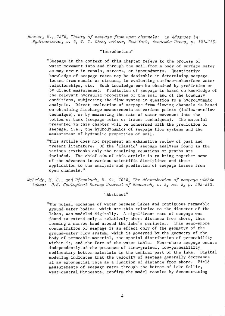
Bouwer, H. , 1969, Theory of seepage from open channels: in Advances inHydroscience, v. 5, V. T. Chow, editor, New York, Academic Press, p. 121-173.
"Introduction"
"Seepage in the context of this chapter refers to the process of water movement into and through the soil from a body of surface water as may occur in canals, streams, or impoundments. Quantitative knowledge of seepage rates may be desirable in determining seepage losses from canals or streams, in evaluating surface-subsurface water relationships, etc. Such knowledge can be obtained by prediction or by direct measurement. Prediction of seepage is based on knowledge of the relevant hydraulic properties of the soil and of the boundary conditions, subjecting the flow system in question to a hydrodynamic analysis. Direct evaluation of seepage from flowing channels is based on obtaining discharge measurements at various points (inflow-outflow technique), or by measuring the rate of water movement into the bottom or bank (seepage meter or tracer techniques). The material presented in this chapter will be concerned with the prediction of seepage, i.e., the hydrodynamics of seepage flow systems and the measurement of hydraulic properties of soil.
"This article does not represent an exhaustive review of past and present literature. Of the 'classic 1 seepage analyses found in the various textbooks only the resulting equations or graphs are included. The chief aim of this article is to bring together some of the advances in various scientific disciplines and their application to the analysis and prediction of seepage losses from op en channels.''
McBride, M. S., and Pfannkuch, H. 0., 1975, The distribution of seepage within lakes: U.S. Geological Survey Journal of Research, v. 3, no. 5, p. 505-512.
"Abstract"
"The mutual exchange of water between lakes and contiguous permeable ground-water bodies which are thin relative to the diameter of the lakes, was modeled digitally. A significant rate of seepage was found to extend only a relatively short distance from shore, thus forming a narrow band around the lake's perimeter. This near-shore concentration of seepage is an effect only of the geometry of the ground-water flow system, which is governed by the geometry of the body of permeable material, the spatial distribution of permeability within it, and the form of the water table. Near-shore seepage occurs independently of the presence of fine-grained, low-permeability sedimentary bottom materials in the central part of the lake. Digital modeling indicates that the velocity of seepage generally decreases at an exponential rate as a function of distance from shore. Field measurements of seepage rates through the bottom of Lake Sallie, west-central Minnesota, confirm the model results by demonstrating
that both the near-shore seepage band and the exponential decrease in seepage velocity actually exist."
Winter, T. C. 3 1976, Numerical simulation analysis of the interaction of lakes and groundwater: U.S. Geological Survey Professional Paper 1001, 45 p.
"Abstract"
"Because the interrelationship of lakes and ground water is perhaps the least understood aspect of lake hydrology, vertical-section, steady-state, numerical-model simulations were run to evaluate the factors that control the interaction of lakes and ground water. The study is concerned only with lakes encircled by water-table mounds that are at a higher altitude than lake level. Simulations of one- lake and multiple-lake systems in vertical sections show that for many hydrogeologic settings, the line (divide) separating local from regional ground-water flow systems is continuous beneath individual lakes. If the divide is continuous, there exists a point along it at which the head is minimum compared to all other points along the divide. This point of minimum head is always greater than the head represented by lake level, therefore in such a setting there can be no movement of lake water through the lake bed to the ground-water system. In a setting where the divide is not continuous, the lake loses water through part of its bed, but rarely in the littoral zone of the lake.
"Factors that strongly influence the position, shape, and continuity of the flow-system divide beneath lakes are height of the water table on the downslope side of the lake relative to lake level, position and hydraulic conductivity of aquifers within the ground-water reservoir, ratio of horizontal to vertical hydraulic conductivity of the ground- water system, and lake depth."
Winter, T. C., 19783 Numerical simulation of steady-state three-dimensional groundwater flow near lakes: Water Resources Research, v. 14, no. 2, p. 245-253.
"Abstract"
"Numerical simulation of three-dimensional groundwater flow near lakes shows that the continuity of the boundary encompassing the local groundwater flow system associated with a lake is the key to understanding the interaction of a lake with the groundwater system. The continuity of the boundary can be determined by the presence of a stagnation zone coinciding with the side of the lake nearest the downgradient side of the groundwater system. For most settings modeled in this study the stagnation zone underlines the lakeshore, and it generally follows its curvature. The length of the stagnation zone is controlled by the geometry of the lake's drainage basin divide on the side of the lake nearest the downgradient side of the ground-

water system. In the case of lakes that lose water to the ground- water system, three-dimensional modeling also allows for estimating the area of lake bed through which outseepage takes place. Analysis of the effects of size and lateral and vertical distribution of aquifers within the groundwater system on the outseepage from lakes shows that the position of the center point of the aquifer relative to the littoral zone on the side of the lake nearest the downgradient side of the groundwater system is a critical factor. If the center point is downslope from this part of the littoral zone, the local flow system boundary tends to be weak or outseepage occurs. If the center point is upslope from this littoral zone, the stagnation zone tends to be stronger (to have a higher head in relation to lake level), and outseepage is unlikely to occur."
Seepage meters
Constant head seepage meters
Meters which Use a Flexible Bag to Measure Seepage
Salinity Laboratory seepage meter (fig. l)
Israelson, 0. W. , and Reeve, R. C., 1944, Canal lining experiments in the Delta Area, Utah: Utah Agricultural Experimental Station, Bulletin 323, p. 15-35.
"Conclusions"
"The cooperative canal lining experimental work in the Delta Area reported herewith leads to the following conclusions:
"1. That careful measurements of seepage losses in canals thatseem to need lining should be made during at least one season before lining.
"2. That seepage losses vary greatly from place to place alongcanals and therefore that current meter or other inflow-outflow measurements may not give all of the information needed as a basis for decision to line the canal or for design of the lining,
"3. That there is an urgent need for new and improved methods of measuring the seepage losses in canals.
"4. That in the Delta Area, natural clays having low permeability suitable for lining canals to reduce seepage losses are abundant.
"5. That lining of many canal sections with clay to preventseepage losses is financially feasible, and that lining some canal sections will pay good returns on the basis of the value of the water saved annually.
"6. That in the Delta Area lining of irrigation canals has value not only in saving water for use on the land, but also in the improvement of drainage conditions, reduction of drainage costs, conservation of soils, improvements of highways, and protection from flooding of basements of public and private buildings.
"7. That improved methods in the compacting of clay for canal lining are urgently needed.
"8. That in large scale operations in clay lining, costs can be greatly reduced by the use of modern heavy machinery for loading, hauling, spreading and compacting the clay.
"9. That long-time continued experimental work is needed to give reliable information with respect to the durability of the lining against erosion, freezing and thawing, moss growth and weed growth in the lined canals."

Warniek3 C. C. 3 1951 3 Methods of measuring seepage toss in irrigation canals: University of Idaho3 Engineering Experiment Station, Bulletin no. 83 42 p.
"Synopsis 1 '
"This bulletin reports progress in the study being made by the Engineering Experiment Station of the University of Idaho in measuring seepage losses from irrigation canals. The study is a cooperative undertaking in which the U.S. Bureau of Reclamation, U.S. Geological Survey, and Post Falls Irrigation District are assisting. The main purpose of the project has been to investigate the various methods of measuring losses to find what improvements might be made, and to develop procedures and equipment which will give more accurate data on the amount and location of seepage losses. Simple procedures involving reliable equipment, which can be economically and conveniently used in the field, have been sought and are stressed in this bulletin.
"Work has centered around field investigations on the canal system of the Post Falls Irrigation District near Post Falls, Idaho, where data were collected on lined and unlined canals. Additional tests were also conducted on laterals of the Black Canyon Irrigation District near Caldwell, Idaho, and in a special tank on the campus of the University at Moscow, Idaho.
"Inflow-outflow method, seepage meters, and the ponding method were used; and results along with recommended procedures and limitations are reported. Evaporation losses were briefly investigated and results are summarized. The ponding method appears to be the most accurate field method but is limited to canals where isolated test sections can be established.
"A new meter proposed for use by the Weber Basin Project, of the Bureau of Reclamation, appears to have possibilities. Future studies should test the meter's characteristics, because the seepage-meter method represents a simple method if consistency can be obtained."
Rasmussen3 W. 3 and Lauritzen3 C. W. 3 19533 Measuring seepage from irrigation canals: Agricultural Engineering, v. 343 p. 326-330.
"Conclusions"
"From the initial investigations of the feasibility and limitations of the seepage meter for estimating seepage losses from specific sections of the canals described under the prevailing conditions it was concluded that:
"1. The erratic and inconsistent results obtained by the seepage meter under certain of the test conditions casts considerable doubt on the reliability of this method for estimating seepage losses from irrigation canals.

"2. The inherent variability in most natural materials will require considerable repetition of measurement to obtain any reliable estimate of such phenomena as seepage and permeability. It appears that any approach to a solution of the problem of determining seepage losses from canals from seepage meter data must be based on statistical methods and the number of seepage-meter measurements required to approach a reliable estimate of seepage from a canal may make the method prohibitive.
"3. The operation of the seepage meter in canals•excavated in cohesionless soils and high-velocity flow is extremely difficult. Undercutting of the seepage cup and tipping of the meters are of frequent occurrence.
"4. From the limited data it appears there is not consistent relation between the seepage rates as determined by the seepage meter and ponding measurements."
U.S. Bureau of Reclamation seepage meter (fig. 2)
Robinson, A. R., and Rohwer, Carl, 1952, Study of seepage losses from Irrigation channels: U.S. Department of Agriculture, Soil Conservation Service, Progress Report, 42 p.
"Summary"
"As in previous seasons of seepage ring operation the effect of time with its related factors was noted as being important in the seepage determinations. Without the additional factor of silting it was found that the seepage rate generally decreased with time but in one case the rate continued to increase during the testing season.
"The 'Effect of Depth Tests' showed that the seepage rate was not directly proportional to the depth of water in the rings. The rate was proportional to the depth plus some length of soil column. This length varied with the location and type of soil.
"The tests conducted to determine the effect of temperature showed that the seepage rate was not constant even after the rings had been in continuous operation for several months. A variation of approximately 20 percent in rates over a 48 hour period was observed at one location with the variation becoming more pronounced after correcting the data for the change in viscosity. An attempt was also made to correct the data for changes in porosity as the volume of air bubbles in the soil changed with vapor pressure. It was observed that the corrections for viscosity and those for changes in vapor pressure were compensating.
"At each seepage ring location measurements of the elevation of the ground water with piezometers showed no change in the position of the water table which could be attributed to seepage ring operation.
"A calibration curve for the seepage meters is presented which shows that for measured rates up to 1.0 feet per day the seepage meters generally measured less than the true seepage rate. For rates of more than 1.0 the seepage meters gave results which were too high.
"By switching the measuring devices on the seepage meters it was determined that the method had no effect on the results of the seepage meter measurements. The rates shown by the SCS and USER seepage meters were usually in close agreement when they were installed side by side.
"It was observed, using the equipment for study of the effect of water table elevation, that as the ground water approached the ground surface there was decrease in seepage rate. The exact relationship of the depth to ground water and the seepage rate was not determined because of uncertainties in the data.
"The studies to determine the relationship of the well permeameter tests to the ponding tests in two canals gave contradictory results. At one location the well permeameter tests gave a permeability which was one-half that determined from the ponding tests while at the other location the well permeameter gave results which were three times those from the ponding tests. Seepage meter tests in one of the canal sections gave results which were very near those for ponding tests."
Rasmussen and Lauritzen, 1953 (see p. 8).
Robinson, A. R., and Rohwer, Carl, 1959, Measuring seepage for irrigation channels: U.S. Department of Agriculture, Agricultural Research Service, Technical Bulletin no. 1203, 82 p.
"Summary"
"When seepage measurements made with seepage meters of the Soil Conservation Service type and the Bureau of Reclamation type were compared with the rates shown by the seepage rings, the results indicated that the seepage meters do not accurately measure seepage but that they do indicate the order of magnitude of seepage rates. Readings taken about a week after installation of meters were generally more accurate than those taken earlier. The average of a series of seepage-meter measurements usually agreed fairly well with the average of a comparable series of seepage-ring measurements if the seepage rate was less than about 1 cubic foot per square foot per 24 hours. For higher rates of seepage, the seepage meters definitely overregister. In highly permeable soil having a surface film of less permeable material, installing a meter breaks the surface seal and allows excessive seepage to take place.
"Seepage-meter results did not differ significantly according to whether the Soil Conservation Service or the Bureau of Reclamation type of meter was used, although the USER meter had a larger bell than the SCS meter. Interchanging the measuring devices on the meters
10

did not affect results. The USER meter is easier to operate; it does not require close attention while the observations are being made.
"Care is needed in setting the meters. Carefully forcing a meter into the soil by means of a jack or by standing on it and rocking gives better results than hammering it into place.
"To obtain satisfactory results with seepage meters in a canal, meters should be installed in the sides of the canal as well as in the bottom."
Hendricks, D. W. _, and Warnick, C. C. y 1961^ A study of the control of canal seepage: University of Idaho^ Engineering Experiment Station, Special- Research Project 20D3 Progress Report no. 2^ 137 p.
"Abstract"
"This report covers four separate and independent sections, which include two field investigations of canal seepage, a study of some aspects of the Weber Basin seepage meter, and a report covering work to date on the piezometer method of measuring hydraulic conductivity for flowing conditions.
"The field investigation on the 28.5 Lateral and South Canal near Homedale, Idaho, utilized the seepage meter and groundwater level readings in auger holes adjacent to the canal. Groundwater contours prepared from these readings did not reveal any local reaches having high seepage-loss rates. The seepage meter test results indicated a seepage rate of 1.0 cfd or less in the 28.5 Lateral.
"The investigation on the 5.6-0.1 Lateral near Homedale also indicated a low seepage-loss rate because of low permeability of the soil. Several deep groundwater observation wells indicated the South Canal which extends nearby at a higher elevation was not a source of seepage in fields adjacent to the 5.6-0.1 Lateral. Poor drainage conditions (i.e., tight soil and hardpan lenses) contribute to waterlogged conditions in the adjacent fields.
"The study of the seepage meter was concerned primarily with the effect of small head variations on measured seepage rate from the seepage bell. A linear relationship was found between the measured seepage rate and the differential head imposed between the inside and outside of the bell.
"The section of the report on hydraulic conductivity by the piezometer method for flowing conditions summarizes knowledge to date and presents an operational equation. Constants involved in the equation were found to be dependent upon the flow net. These constants were evaluated by means of an electrical analog. The reliability of the new piezometer equation was checked by comparing hydraulic conductivities obtained from (1) independent permeameter tests and (2) the piezometer method. These tests were conducted in a seepage
11
ring area in the field and also in a sand model in the laboratory. All these evaluations were made for particular saturated flow situations. Reasonable agreement for these comparisons was obtained and it appears that the piezometer and the proposed equation developed through this study can be used to evaluate seepage loss rates from the bottom of a canal."
U.S. Bureau of Reclamation, 1963, Seepage investigations: in Linings for Irrigation Canals, Washington, D.C., U.S. Government Printing Office, p. 13-28 (excerpt from text).
"Seepage Meter Method.-The seepage meter (fig. 3) is a modified version of the constanthead permeameter developed for use under water. It consists of a watertight seepage cup connected by a plastic tube to a flexible water bag. Water flows from the bag into the cup where it seeps through the 2 square feet of canal subgrade area isolated by the cup. By keeping the water bag submerged, the heads on the areas within and outside of the cup are equal. The seepage rate may be computed from the weight of water lost in a known period of time and the area under the meter.
"The seepage meter is not considered an accurate means of measuring seepage loss. Its main value lies in determining approximate locations of relatively high seepage losses. If tests are made at close intervals throughout a reach, a better indication of the average loss rate can be determined."
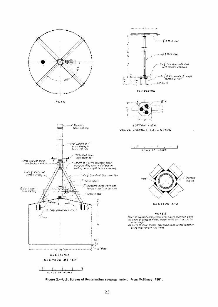
MoBirney, W. B., 1961, Measuring seepage loss in irrigation canals: Bureau of Reclamation, Hydraulic Laboratory Report HYD-459, 19 p. (excerpt from text).
"There are several known methods for determing seepage losses and others are in process of development. However, at present, there are three generally used methods for determining losses quantitatively; ponding, seepage meter, and inflow-outflow. Of these three, sufficient information is available to present a general procedure for conducting seepage loss tests by the ponding and seepage meter methods. There is insufficient information presently available to establish the best procedure for the inflow-outflow method.
"Many factors affect the rate of seepage loss from a canal. Some of the more obvious ones are listed here:
"1. Permeability of material traversed by canal"2. Depth of water"3. Wetted area"4. Location of water table relative to canal invert"5. Slope of subgrade soil structure"6. Flow velocity"7. Soil and water temperatures"8. Entrained air in soil"9. Ground-water inflow
12

"10. Atmospheric pressure"11. Soil and water chemistry"12. Capillary attraction
"The relative importance of each has not been definitely determined, though it is known that one may offset another, and some may even alternately produce an increase and a decrease in seepage rate.
"With so many variables operating, it is considered impossible to write simple equations expressing the interrelationships which may exist. The theoretical approach to computing seepage losses must then be supplanted with empirical methods."
Cut-off 55-gallon drum seepage meter (fig. 3)
Lee, D. R., 1972, Septic tank nutrients in ground water entering Lake Sallie, Minnesota: M.S. Thesis, University of North Dakota, Grand Forks, 96 p.
"Summary"
"A simple, inexpensive, seepage collector permits direct measurement of groundwater inflow in the range 0.01 to 2.5 y m/s (0.003 to 0.71 ft/day). It can be used to obtain samples of groundwater inflow for chemical analysis and appears useful for groundwater studies.
"Groundwater inflow contributed materially to lake volume. Inflow continued year-round at measurable rates but increased by a factor of two to three in spring. Along 800 m shore, groundwater entered Lake Sallie at the rate of 4.50 x 10 5 m3 /year. The velocity of inflow was quite uniform along the margin of the lake but decreased exponentially with distance from shore, a pattern that is predictable on the basis of flow net construction and a small number of test holes.
"About 300 kg of nitrate nitrogen entered Lake Sallie annually along 400 m of shore, and is apparently associated with, but not restricted to, fertilization of adjacent cropland.
"Study of a lakeside septic tank, selected on the basis of heavy use and the presence of seepage inflow, indicated that 40% of its affluent nitrogen reached the lake. Contaminants traveled in a fan-shaped zone along the surface of the water table and entered the lake near the shoreline. Lakeside septic tanks appear to be an immediate source of nitrogen. Phosphate was fixed in the soil near the septic tank.
"Comparison of seepage chemistry at two locations on the northeast shore suggested that nearby Muskrat Lake contributes not only ground- water but also phosphorus and nitrogen to Lake Sallie."
13

Lee3 D. R. 3 19763 The role of ground water in eutrophication of a lake in glacial outwash terrain: International Journal of Speleology 3 v. 83 p. 117-126.
"Summary"
"The nutrient contribution of groundwater in glacial outwash terrain was evaluated at Lake Sallie in north-central U.S.A. (46°46'N., 95°54'W.). Groundwater entering the lake was collected with seepage meters consisting of bottomless cylinders vented to a thin membrane bag. A theoretical flow net and comparison of nutrient concentrations in well and seepage water indicates that seepage meters can be used in high velocity discharge areas to obtain site-specific water samples of groundwater for nutrient analyses."
Lee3 D. R. 3 19773 A device for measuring seepage flux in lakes and estuaries: Limnology and Oceanography3 v. 223 no. 1 3 p. 140-147.
"Abstract"
"Seepage flux can be measured and samples of groundwater flowing into lakes and estuaries collected by enclosing an area of bottom with a cylinder vented to a plastic bag. The method has the advantage of not requiring measurements of permeability of bottom sediments. Seepage velocities from -0-2.58 ym s" 1 were measured in Minnesota and Wisconsin lakes and in Nova Scotia and North Carolina estuaries.
"Where seepage inflow was rapid (0.4-0.8 ym s" 1 ), water collected with the seepage meter was chemically similar to water from wells on the same flow path, and the distribution and chemistry of the seepage concurred with a theoretical flow net. The rate and direction of seepage flux were correlated with water surface elevation during a tidal cycle."
Lee3 D. R. 3 and Hynes3 H. B. N. 3 1978, Identification of groundwater discharge zones in a reach of Eillman Creek in southern Ontario: Water Pollution Research Canada3 v. 133 p. 121-133.
"Abstract"
"Several new techniques were used to identify zones of groundwater and contaminant inflow to the headwaters area of a small stream draining an agricultural watershed in southwestern Ontario. Along a 3 km length of stream, seepage meters were used to measure and collect seepage flux and mini-piezometers were used to measure piezometric head relative to the stream and to collect pore water 0.6 m below the streambed.
"Measurement of seepage flux at 43 locations along a 3 km segment of Hillman Creek showed that most of the study section was a groundwater discharge zone. Spatial differences in seepage flux ranged from less
14
than 0.001 to nearly 9 cm3 m 2 s *. During the growing season there was a marked diurnal change in seepage rate at several locations and this was also reflected by a corresponding change in stream discharge.
"Paired samples, one from a piezometer 0.6 m below streambed and one from the adjacent seepage meter, were significantly correlated (P < 0.01) with respect to specific conductance, chloride and inorganic carbon concentration. This suggested that in many instances site-specific estimates of chemical inputs from groundwater to surface water can be estimated quickly without the necessity of allowing natural groundwater flow to flush out the water initially trapped within the seepage container. Seepage meters can be used to measure seepage flux and the small piezometers can be used to obtain samples. The concentrations of non-conservative solutes (organic carbon, nitrate + nitrite nitrogen, and phosphate) in seepage meter samples were not significantly correlated with the concentrations in corresponding mini-piezometer samples. 11
Lee3 D. R., and Cherry, J. A., 1978., A field exercise on groundwater flow using seepage meters and mini-piezometers: Journal of Geological Education, v. 2?3 p. 6-10.
"Abstract"
"Basic principles of physical hydrogeology and the nature of the hydrologic interactions between groundwater and surface water can be convincingly demonstrated in the field using two inexpensive and easily constructed devices known as the miniature piezometer and the seepage meter. These instruments have been successfully used during a hydrogeology field course at the University of Waterloo and have been adopted as a routine teaching aid. Seepage meters and miniature piezometers are inserted in the sediment of shallow areas in lakes, estuaries, or streams. In a matter of a few hours, the devices can be installed, monitored, and removed. Information on the direction and rate of groundwater flow can be obtained. Hydraulic conductivity can be measured using several types of tests.
"Samples of the groundwater can be collected and, with field measurements of parameters such as specific conductance, dissolved oxygen, pH, and chloride, comparisons between groundwater and surface water quality can be made. Student investigations can include the identification of groundwater inflow or outflow areas in lakes, streams, or estuaries, measurement of the spatial and temporal variations in seepage flux through bottom sediments, and identification of zones of subsurface pollutant migration into surface waters. A day of equipment preparation and a preliminary site visit are prerequisites to the student field activities. Materials for a seepage meter and a miniature piezometer can be acquired for less than 25 dollars."
15

Downing,, J. A. 3 and Peterka3 J. J. 3 19783 Relationship of rainfall and lake groundwater seepage: Limnology and Oceanography 3 v. 233 no. 43 p. 821-825.
"Abstract"
"Correlations were found between mean daily rainfall and groundwater inflow rate and between the rate of groundwater inflow and N and P inflow to a senescent lake during summer. A simple method of collecting and measuring groundwater inflow was reproducible at very low inflow rates. The water collected by this method was similar in P concentration to groundwater but higher in N concentration."
Erickson3 Denis R. 3 19793 The hydrogeology of Williams Lake3 Minnesota with special emphasis on quantification of littoral groundwater contributions using seepage meters and wells: M.S. Thesis 3 University of Minnesota3 153 p,
"Abstract"
"Williams Lake, Hubbard County, north-central Minnesota, is a 90 acre lake, hydrologically connected with the surrounding groundwater flow. Evaporation and precipitation normals of the area are approximately equal. The littoral groundwater contribution to the lake was measured with seepage meters, after calibration and development of a reliable field technique in the laboratory, and piezometers. Groundwater flux rates determined by each method at specific sites were in relatively close agreement. Combining the information of both methods, the lake inseepage/outseepage boundary (hingeline) could be approximately located. The regime within Williams Lake littoral zones was predominantly outseepage. Much of the groundwater inflow appeared to be directed toward wetland depressions adjacent to the lake. Comparisons of measured littoral groundwater contributions with water budget residual values were in general agreement, however, the evaporation components of the water budgets were approximations."
Lee, D. R. 3 Cherry3 J. A. 3 and Pickens3 J. F. 3 19803 Groundwater transport of a salt tracer through a sandy lakebed: Limnology and Oceanography 3 v. 25 3 no. 1 3 p. 45-61.
"Abstract"
"In an investigation of groundwater advection and dispersion in a lakebed, a vertical zone of salt solution (CaCl») was injected between 1.7 and 3 m beneath the shoreline and was observed to enter the lake through a large area of lakebed at a reduced concentration. Migration of the tracer pulse and flux to the lake were monitored over a 7 x 8 m area of lakebed by measuring the electrical conductance of water collected from 304 sampling points beneath the lakebed and from 25 seepage meters on the lakebed. The tracer moved horizontally,
16

r\
curved gently upward, and entered the lake through an area If 17 m^ - an area 5.7 times larger than the initial cross-sectional area of the tracer zone. Along a 6 m migration path to the lake, peak concentration of tracer declined to 31 percent of the initial value. Seepage flux through the sediment-water interface declined exponentially with offshore distance and averaged 240 m 3 yr" 1 per meter of shoreline.
"Results showed that prediction of the magnitude and distribution of lakebed contaminant flux from onshore zones of groundwater contamination requires consideration of dispersivity and anisotropic permeability. Numerical simulations were used to produce quantitative flow nets. As the anisotropy ratio was increased from 1 to 20, hypothetical tracer-entry areas extended over larger areas of lakebed and were displaced farther offshore. A ratio of 10 matched the field data. An analytical solution to a one-dimensional form of the advection-dispersion equation showed that the decline in peak concentration of the tracer was sensitive to small changes in longitude dispersivity, and that the longitudinal dispersivity of the tracer zone was on the order of 1 cm."
New Zealand seepage meter (no diagram available)
John, P. H. , and Lock, M. A., 1977, The spacial distribution of groundwater discharge into the littoral zone of a New Zealand lake: Journal of Hydrology, v. 33, p. 391-395.
"Abstract"
"The spacial distribution of groundwater discharge into the littoral zone of Lake Rotorua (New Zealand) was determined by direct measurement. Discharges at two stations on the eastern shore were found to be 2.8 and 5.0 times greater than that at any of the other five stations gauged. On transects at right angles to the shoreline, flow rate varied inversely with depth and distance from shore. The maximum discharge recorded was 127.5 1 m'^day" 1 , and the minimum 2.7 1 m~2 day-1 . It is concluded that the technique employed could be an extremely useful tool when investigating groundwater discharge into lakes."
Weber Basin or Mariotte Siphon Seepage Meter (fig. 4)
Warnick, 1951 (see p. 8).
Hendricks and Warnick, 1961 (see p. 11).
17
Warnick, C. C., 1965, Problems in seepage evaluation and control: U.S. Department of Agriculture, ARS 41-90, Seepage Symposium Proceedings 1963, p. 132-137.
"Introduction"
"Seepage evaluation, like all the measurements men have tried to make, tends toward the need and desirability of a better and a more precise quantitative value. Fortunately, today the tools are better, but really we are still very crude in our methodology. After seeking better ways, it is discouraging to report we do not have an answer sufficiently accurate to indicate where we should control seepage or where it is the problem."
Constant Head Overflow Seepage Meter (fig. 5)
Hendricks and Warnick, 1961 (see p. 11).
Warnick, 1965 (see above).
Variable head seepage meters
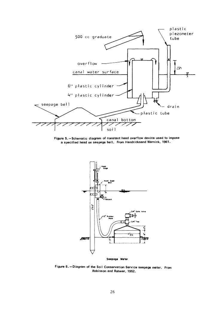
Soil Conservation Service Seepage Meter (fig. 6)
Robinson and Rohwer, 1952 (see p. 9).
Robinson and Rohwer, 1959 (see p. 10).
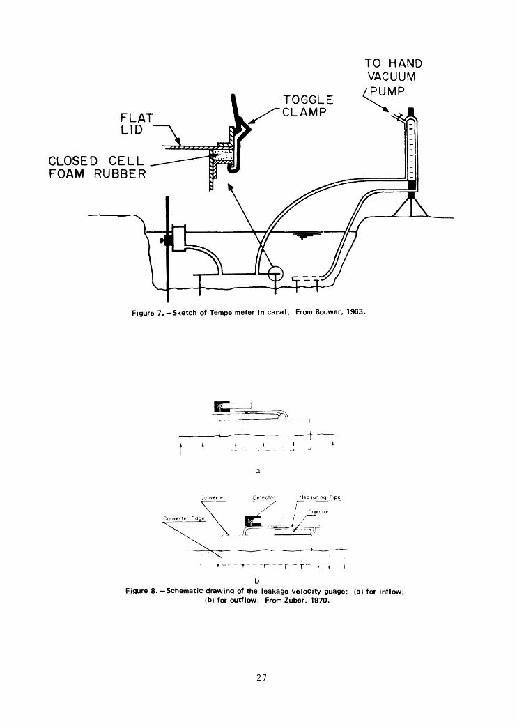
Tempe Seepage Meter (fig. 7)
Bouwer, H., 1961, Variable head technique for seepage meters: American Society of Civil Engineers Proceedings, v. 87, Journal of Irrigation and Drainage Division (IRI), p. 31-44.
"Synopsis"
"A technique for measuring canal or reservoir seepage losses with seepage meters is proposed. The method also furnishes information regarding hydraulic conductivity of bottom material and seepage gradients. A resistance network analog was used for analyses of pertinent factors and flow components and for obtaining examples to illustrate the method. "
18

Bouwer3 H. 3 and Rice, R. C. 3 19633 Seepage meters in seepage and recharge studies: American Society of Civil Engineers Proceedings,, v. 89 3 Journal of the Irrigation and Drainage Division (IRI) 3 p. 17-42.
"Synopsis"
"Previously published principles for measuring seepage and hydraulic conductivity of bottom material with seepage meters are extended to head-affected seepage and stratified bottom materials. The theory is reduced to simple field procedures, which may be applied to investigate seepage, to evaluate soil sealants for reducing seepage, or to analyze ground-water recharge installations."
Bouwer3 H. 3 19653 Application of seepage meters: U.S. Department of Agriculture3 ARS 41-903 Seepage Symposium Proceedings 19633 p. 77-81.
"Introduction"
"Seepage meters are in principle suitable devices for measuring local seepage rates in canals or ponds. However, erratic results have sometimes been reported, and the need for refinements in equipment and techniques has been recognized. This paper reports on studies that were performed to identify and eliminate, as much as possible, sources of error. In the course of these studies, it became apparent that seepage meters not only can be used to measure seepage but also to evaluate hydraulic conductivity of bottom material and seepage gradients.
"Seepage meters are cup- or bell-type devices. A common diameter is approximately 1 foot. The cylinder part, which is approximately 8 inches high, is pushed a small distance into the canal bottom. If the pressure head inside the seepage meter equals that in the canal, the outflow from the seepage meter is a measure of the seepage of the portion of the bottom that is enclosed by the seepage meter. Thus, the principle of measuring seepage with seepage meters is to maintain a pressure inside the seepage meter that is equal to that outside the seepage meter and to measure, at the same time, the outflow from the seepage meter. This, however, is easier said than done.
"There are at least three possible sources of error in measuring seepage with seepage meters. One may be in the disturbance of the bottom material when the meter is installed. Errors also may be introduced if, when the outflow from the seepage meter is measured, the pressure head inside the meter is not exactly equal to that due to the free water surface which is generally taken as a reflection of the pressure head around the meter.
"Errors due to disturbance of the bottom material may be reduced by minimizing the depth of penetration of the seepage meter into the canal bottom. In this case, however, it is necessary to prevent any
19

surges inside the meter while the meter is pushed into the canal bottom. The surges may cause blowouts or imperfect contact between the seepage meter and the canal bottom material. To minimize pressure surges inside the seepage meter as it is forced into the canal bottom, a meter with a completely removable lid is recommended. Prior to installation, the lid is removed from the meter. After the desired depth of penetration has been reached, the lid is replaced.
"Errors produced when the pressure head inside the seepage meter was not exactly equal to that outside the seepage meter during measurement of outflow from the meter were analyzed by resistance network analog. The analyses indicated that when seepage gradients are low, a small head difference of one-half inch or so could cause errors in the measured seepage that approached the magnitude of the seepage itself. For high seepage gradients, such pressure differences cause only a small error in the measurement. In general, it is advisable to base the seepage measurement on a pressure head inside the seepage meter that is as close as possible to that outside the seepage meter."
Bouwer3 E. 3 and Rice3 R. C. 3 19683 Review of methods for measuring andpredicting seepage: U.S. Department of Agriculture3 Agricultural Research Service 41-1473 Proceedings of the Second Seepage Symposium, p. 115-120.
"Summary"
"Direct measurement of seepage can be obtained by inflow-outflow, ponding, seepage-meter, and salt-penetration techniques. The latter is a recently developed tracer technique whereby seepage is determined from the rate of advance of dissolved salt in the bottom material. The advantages and disadvantages of the various techniques are discussed. Another approach for obtaining quantitative seepage information is to calculate the seepage rate from a knowledge of the hydraulic conductivity profile of the soil and the position of the ground-water table. Solutions can be obtained by mathematical analysis or by analog or model studies. Analyses by resistance net work analog and the resulting dimensionless graphs for determining the seepage rate are discussed. In certain cases, it will be of interest to know seepage in relation to time after water has entered a dry channel. This is essentially a problem of two-dimensional infiltration; it shows how simplified solutions can be obtained."
Leakage velocity seepage meter (fig. 8)
Zuber3 A. 3 19703 Method for determining leakage velocities through thebottom of reservoirs: in Isotope Hydrology, Vienna, International Atomic Energy Agency, p. 761-777.
20

"Abstract"
"A new method based on an idea of converting a slow flow through a chosen area of reservoir bottom to a fast flow in a pipe of a small diameter is presented. If the chosen area is tightly covered by a bottomless cylinder with an outlet through a pipe then the product of leakage velocity and the area covered is equal to the product of flow velocity in the pipe and the pipe cross-section. Even extremely low leakage velocities render measurable velocities in the pipe if its cross-section is very small in comparison with the covered area. This method can be used for leakage velocity measurements if the measuring device does not disturb natural flow lines. Conditions under which this requirement is satisfied are considered in detail. A measuring device constructed according to these conditions and described in the paper can measure leakage velocities from 5 x 10" 7 to 3 x 10~ 3 cm/sec. The flow velocity in the measuring pipe is known from the transit time measurement of an injected pulse of a radioisotope."
21

fa)
Ht Rvt>btr ri/bin« \ Conntct fo \Vat*rBaf: fa I To fill bay.
\ fbl To conrtjr water
TOP VIEW to soil
0 -0)1
3-1" Holft /£r*n/y Spa
(b)
SIDE ELEVATION CLCVATION
Figure 1.—Salinity Laboratory seepage meter, (a) From Israel son and Reeve, 1944; (b) From Warnick, 1951.
22
'----- f 0 Mild steel
,-----\* Mild steel
,'--£"* -f' Flat stock mild steel ' with corners removed
,---•3- j- 0 Mild steelx If" length spaced @ 120*
,---60° Bevel
ELEVATION
PLAN
Strap weld not shown, » see Section A-A--------
4 -i "xy" Mild steel straps 17" long- -^
-----/" Standard black iron cap
5-0" Length of i" extra strength black iron pipe
^-/"Standard black iron coupling
•-?"Length of i" extra strength black iron pipe Plug lower end of pipe by welding water-tight before assembly
-y~-i- ----/"/ I"K I' Standard black iron Tee
----T" C/ose nipple
BOTTOM VIEW
VALVE HANDLE EXTENSION
SCALE OF INCHES
Weld---
j 0 D copper tube 2 f long ----
-•?" Standard globe valve with handle in vertical position
J\\-----/" Close nipple
,--/" Standard coupling
SECTION A-A
NOTESPoint oil exposed ports, except brass, with aluminum paint All welds an seepage meter, except welds on straps, to be
water-tight All ports af valve handle extension to be welded together
using appropriate sue welds
_ /9 " Bevel
ELEVATION
SEEPAGE METER
SCALE OF INCHES
Figure 2.—U.S. Bureau of Reclamation seepage meter. From McBirney, 1961,
23

water surface
Figure 3.—Cut-off 55-galIon drum seepage meter. From Lee and Cherry, 1978. (Full section view of seepage meter showing proper placement in sediment. A. 4 liter, 0.017 mm membrane plastic Baggies Alligator bag (open end was heat sealed); B. rubber-band wrap; C. 0.64 cm inside diameter, 6 cm long, polyethylene tube; D. 0.79 cm inside diameter, 4.5 cm long, amber-latex tube; F. 15 cm x 57 cm diameter epoxy -coated cylinder (end -section of a steel drum); G. 0.64 cm inside diameter, polyethylene tube long enough to reach above the surface water.)
24

(a)
BASIN
(b)glass tube
canal water surface
;:>! ast i c )i ezometer tube
Ah
lastic tube
Figure 4. -Weber Basin or Mariotte siphon seepage meter: (a) from Warnick, 1951; (b) from Hendricks and Warnick, 1961.
25
500 cc graduate
,-— plast ic\ piezometer\ tube
\-^
overflow —— — — "
canal water surface
6" plastic cylinder — -""^
4" plastic cylinder — ̂
/
^
~\ V S
_^k_
>
j
2
j
I
IAH J —— f—
^— dra i n
lastic tube
Figure 5.--Schematic diagram of constant head overflow device used to impose a specified head on seepage bell. From Hendricksand Warnick, 1961.
Seepage Meter
Figure 6.-Diagram of the Soil Conservation Service seepage meter. From Robinson and Rohwer, 1952.
26
TO HANDVACUUMPUMP
CLOSED CELL FOAM RUBBER
TOGGLE CLAMP
Figure 7.--Sketch of Tempo meter in canal. From Bouwer, 1963.
i t
Figure 8. —Schematic drawing of the leakage velocity guage: (a) for inflow; (b) for outflow. From Zuber, 1970.
27
Potential probes, hand-driven
Hvorslev3 M. J. j 1951., Time lag and soil permeability in groundwaterobservations: U.S. Army Corps of Engineers 3 Waterways Experiment Station Bulletin no. 363 55 p.
"Introduction"
"Ground-water levels and pore-water pressures are determined by means of borings, observation wells, or various types of piezometers and hydrostatic pressure cells. During the advance of a bore hole or immediately after installation of a pressure measuring device, the hydrostatic pressure within the hole or device is seldom equal to the original pore-water pressure. A flow of water to or from the boring or pressure measuring device then takes place until pressure differences are eliminated, and the time required for practical equalization of the pressures is the time lag. Such a flow with a corresponding time lag also occurs when the pore-water pressures change after initial equalization. It is not always convenient or possible to continue the observations for the required length of time, and adequate equalization cannot always be attained when the pore-water pressures change continually during the period of observations. In such cases there may be considerable difference between the actual and observed pressures, and the latter should then be corrected for influence of the time lag.
"The magnitude of the time lag depends on the type and dimensions of the pressure measuring installation, and it is inversely proportional to the permeability of the soil. A preliminary estimate of the time lag is necessary for the design or selection of the proper type of installation for given conditions. The actual time lag should be determined by field experiments so that subsequent observations may be corrected for its influence, when conditions are such that corrections are required or desirable.
"Theoretical and experimental methods for determination of the time lag and its influence on the results of pressure measurements are presented in this paper. These methods are based on the assumptions usually made in the theories on flow of fluids through homogeneous soils, and the results are subject to corresponding limitations. In addition to the time lag, ground-water observations may be influenced by several other sources of error and by irregular and changing ground-water conditions. Therefore, an initial review of ground-water conditions in general and of the principal sources of error in determination of ground-water levels and pressures is desirable in order to clarify the assumptions on which the proposed methods are based, and to delimit the field of application of these methods."
28

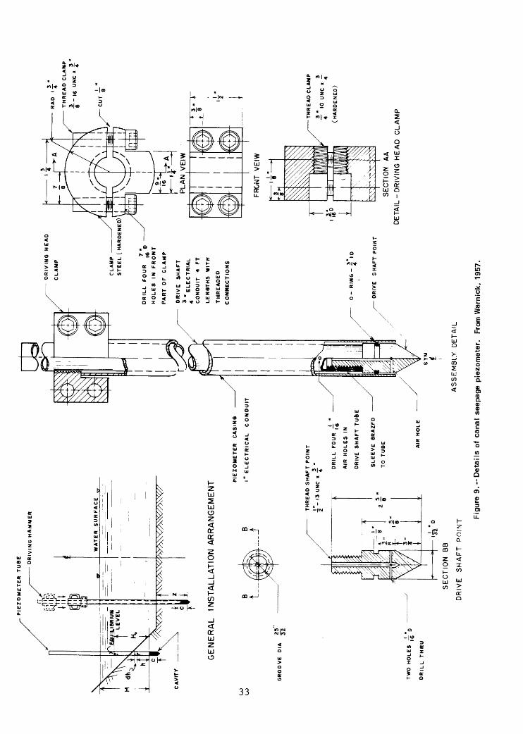
Warnick,, C. C. 3 19573 A study of the control of canal seepage: University of Idaho3 Engineering Experiment Station, Special Research Project no. 20-C3 Progress Report no. 1 3 38 p. (fig. 9).
"Synopsis"
"This progress report presents a resume of work carried on during 1956-57 and summarizes the findings during that time. The report is primarily for the review of groups interested in the field of water resource conservation and development so they might know of the problems, results and plans of this Special Research Project 20-C, The principal aim of this cooperative study by the Engineering Experiment Station of the University of Idaho and Region I of the Bureau of Reclamation has been to determine the value and effective ness of different linings and earth treatments in preventing conveyance losses in irrigation. An important phase of this has been a continuing effort to perfect methods of measuring conveyance losses from canals. Funds for this project have been made available through the University Special Research Program and the Lower-Cost Canal Lining Program of the Bureau of Reclamation. Field experiments were conducted on the canals of the Black Canyon Irrigation District near Caldwell.
"Four test sections of experimental linings were tested for seepage loss by the ponding method and all sections of prefabricated asphalt lining were tested with the electrostatic holiday detector. Several visual inspections of all experimental linings were also made during the year. A by-pass test section of an operating lateral was constructed in 1956 to permit testing and ponding in either the original channel or the new by-pass section. This was done to offer control testing to several of the methods proposed for measuring seepage loss. Special seepage piezometers were developed and techniques for installing them studied as a new method of evaluating seepage loss. Specifications for these piezometers are included in the report and theory is explained for adapting the piezometers to canal seepage loss measurements. Special seepage rings were also constructed and used to evaluate the performance of the seepage piezometers. Air permeameters were further studied, more versatile designs have been proposed and the method of installing the units greatly improved. The effects of moisture in the soil on air permeability results was studied in sand soils and depth of insertion of the seepage bell varied to evaluate this parameter in the use of the air permeameter.
"Ponding tests showed very slight changes in the seepage loss characteristics of two of the experimental sections. One exposed prefabricated asphalt lining continued to show signs of failure in the form of transverse cracks in the invert of the test lateral. Asphaltic mastic on one of the sections appears to have particularly durable characteristics. The seepage piezometer has apparently given a new approach to the evaluation of seepage losses from
29
canals, although some discrepancies exist when compared with results from ponding tests and seepage ring tests, this method appears to have much merit where saturated flow exists below the canal boundary. Results from air permeameter tests have better defined the limits of use of this air permeability method, which offers a possible way of evaluating loss characteristics in canals that do not have1 water in them."
Hendricks and Warnlck3 1961 (see p. 11).
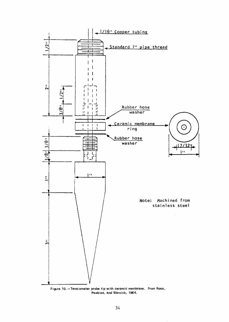
Ross3 J. A. 3 Peebles, J. J. 3 and Wamlck, C. C. 3 19643 A study of the control of canal seepage: University of Idaho3 Engineering Experiment Station, Special Research Project no. 20D3 Progress Report no. 53 79 p. (figs. 10 and 11).
"Abstract"
"This progress report summarizes experimental work performed during 1963 and 1964 on Special Research Project 20D, a cooperative study with the U.S. Bureau of Reclamation to investigate methods of measuring conveyance losses in canals and to evaluate various canal lining materials. The report covers descriptions of experiments with piezometer tubes, tensiometers, no-flow pressure calls, a double-tube infiltrometer and a seepage meter. In addition, a search for a new experimental canal site and experiments with punctured butyl rubber lining are described.
"On the basis of laboratory and field experiments with piezometers to measure seepage for the horizontally-flowing ground water condition, it was found that the constants in the hydraulic conductivity equation were the same as for the vertically-flowing and non-flowing ground water conditions. For field tests in 1963 adjacent to the 10.2-1.4 bypass, values of hydraulic conductivity ranging from 0.53 to 0.60 feet per day were obtained for the horizontally-flowing ground water condition.
"Field tests of piezometer tubes were made in sandy soil at the 10.2 lateral seepage ring site in 1963 and in silty soil at the Notus seepage ring site in 1964. Values of hydraulic conductivity ranging from 19 to 134 feet per day were obtained at the 10.2 lateral site as compared to values of 24 to 74 feet per day by the ponding method. At the Notus site, hydraulic conductivity by piezometers ranged from 0.05 to 0.91 feet per day as compared to 0.83 to 1.94 feet per day by the ponding method. At both sites variation in seepage rates with variation in barometric pressure was noted.
"During both 1963 and 1964 an attempt was made to develop a tensiometer and no-flow pressure cell to measure pressure gradients in unsaturated flow zones. Although no reliable data were obtained, tests did suggest that this equipment was very sensitive to heat.
30
"To obtain seepage rates for comparison with rates obtained by the ponding and piezometer methods, tests with a double-tube infiltrometer were made during 1963 and 1964, and tests with a seepage meter were made during 1964. The double-tube infiltrometer gave values of 20 to 53 feet per day at the 10.2 lateral seepage ring site and 0.11 to 0.47 feet per day at the Notus site. The seepage meter gave values of 0.82 to 2.20 feet per day at the Notus site."
FokkenSj B. 3 and Weijenberg, «/._, 1968^ Measuring the hydraulic potential of groundwater with the hydraulic potential probe: Journal of Hydrology> V. 63 p. 306-313 (fig. 12).
"Abstract"
"The 'potential probe 1 , which was used by the authors during two years on a rather large scale, is a new instrument to measure hydraulic potentials in saturated soils without disturbing the soil profile. A second advantage is that the basic lag time of the apparatus is about 15 times shorter than that of normal one inch tube piezometers."
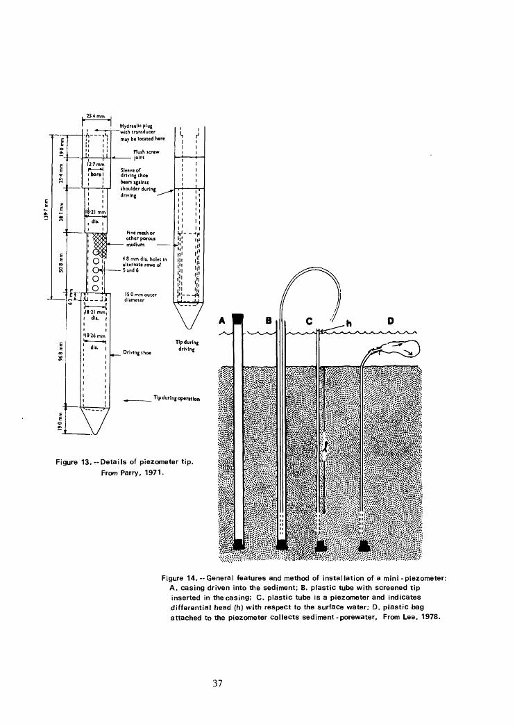
Parry, R. H. G., 1971 3 A simple driven piezometer: Geotechnique, v. 21 3 no. 23 p. 163-167 (fig. 13).
"Summary"
"The basic advantage of this type of piezometer is that it can be installed in porous deposits underlying clay deposits without damaging the porous element on stones or hard seams in the clay and without smearing or clogging the porous element. However, it is necessary to know beforehand the depth of the porous layer, although in the case of sand a sharp rise in the driving resistance usually occurs on entering the sand layer.
"For long term operation it is advisable to use non-corrosive metal such as brass for the tip and porous element, although the mild steel tips used at Soham Lode were still operating successfully 15 months after installation. In soft ground it is possible that hard plastic could be used for the tip and standpipe rather than metal.
"It seems that the tip could be developed for use in clays, although the possibility of smearing of the cavity wall must be recognized. However, the response shown in Fig. 5 and the resulting calculated permeability suggest that the tip was operating successfully. However, it would be preferable to use a porous element of ceramic, plastic or porous bronze rather than the mesh. An unprotected ceramic piezometer for pushing into soft clay at the base of a borehole has been used successfully by Wilkes (1970).
31

"An open standpipe would obviously not be adequate for use in clays and this can be overcome by inserting an hydraulic sealing plug immediately above the tip as shown in Fig. 2. This plug can be inserted after the tip has been driven to its predetermined depth. The plug could be fitted either with twin hydraulic lines to allow pore pressure measurements by means of a closed hydraulic circuit or it could be fitted with an electrical transducer. An advantage of this electrical transducer over most electrical field piezometers is that it could be removed at any time for recalibration. Work on a plug of this type is proceeding at Cambridge.
"A further development, when using the hydraulic sealing plug, might be to extract after driving all rods above the 1 m length of sealing rod, bringing only the twin hydraulic lines or electrical cable to the surface. However, in this case the electrical transducer could not be extracted for recalibration."
Lee and Chewy, 1978 (see p. 15 and fig. 14).
32
PIE
ZO
ME
TE
R
TU
BE
DR
IVIN
G H
AM
ME
R
\ 'f
X—
——
—
--T
*.^
1^"
H dh,
is
EQUI
LIBR
IUM
* |
LE
VE
L
CA
VIT
Y
WA
TE
R
SU
RF
AC
E
GENERAL
I NSTALLATION ARRANGEMENT
to
to
25
PIE
ZO
ME
TE
R
CA
SIN
G
("E
LE
CT
RIC
AL
C
ON
DU
IT
TW
O
HO
LE
S
.-=
016
DR
ILL
T
HR
U
TH
RE
AD
S
HA
FT
P
OIN
T
- 1
3 U
NC
«
-r
DR
ILL
F
OU
R
,—
I o
AIR
H
OL
ES
IN
DR
IVE
S
HA
FT
T
UB
E
SL
EE
VE
8R
AZ
FD
TO
T
UB
E AIR
H
OL
E
SE
CT
ION
B
B
DR
IVE
S
HA
FT
P
OIN
T
DR
IVIN
G
HE
AD
CL
AM
P
TH
RE
AD
C
LA
MP
-16
U
NC
«-"
CL
AM
P
ST
EE
L
(.H
AR
DE
NE
D)
DR
ILL
F
OU
R
HO
LE
S
IN
FR
ON
T
PA
RT
D
F
CL
AM
P
DR
IVE
S
HA
FT
EL
EC
TR
IAL
CO
ND
UIT
4
F
T
LE
NG
TH
S
WIT
H
TH
RE
AD
ED
CO
NN
EC
TIO
NS 3
"
DR
IVE
S
HA
FT
P
OIN
T
AS
SE
MB
LY
D
ET
AIL
Fig
ure
9.-
-Deta
ils o
f ca
na
l se
ep
ag
e p
iezo
me
ter.
F
rom
Wa
rnic
k,
1957.
SE
CT
ION
A
A
DE
TA
IL-D
RIV
ING
HE
AD
C
LA
MP
CM
CO
co
CO
^ 1/16" Copper tubing
Standard 1" pipe thread
liii 1*11
Rubber hose washer
Ceramic membrane ring
hose washer
Note: Machined from stainless steel
Figure 10. --Tensiometer probe tip with ceramic membrane. From Ross, Peebles, and Warnick, 1964.
34

l.A" I .D. tubing
Porvic paper disk
1/16" Dia. port
1/12" Dia
Dia.
Figure 11.—Tensiometer probe tip with porvic paper membrane. From Boss, Peebles, and Warnick, 1964.
35
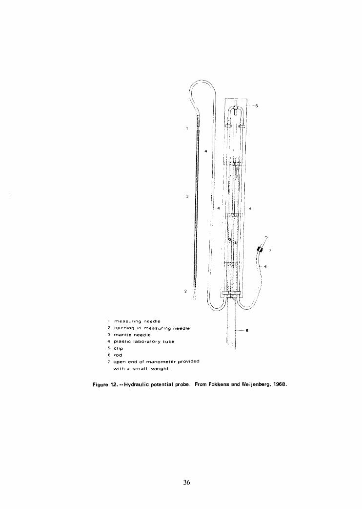
1 measuring needle
2 opening in measuring needle
3 mantle needle
4 plastic laboratory tube
5 clip
6 rod
7 open end of manometer provided
with a small weight
Figure 12.—Hydraulic potential probe. From Fokkens and Weijenberg, 1968.
36
Sleeve of driving shoebears against shoulder during driving
48 mm dla. holes In alternate rows of 5 and 6
Tip during operation
Figure 13.— Details of piezometer tip.
From Parry. 1971.
Figure 14. — General features and method of installation of a mini -piezometer: A. casing driven into the sediment; B. plastic tube with screened tip inserted in the casing; C. plastic tube is a piezometer and indicates differential head (h) with respect to the surface water; D. plastic bag attached to the piezometer collects sediment-porewater. From Lee, 1978.
37
Index of authors
PageBouwer, 1961—————————————————————————————————————————— 18Bouwer and Rice, 1963——————————————————————————————————— 19Bouwer, 1965—————————————————————————————————————————— 19Bouwer and Rice, 1968————————————————————————————————————— 20Bouwer, 1969—————————————————————————————————————————— 4Cedergren, 1967—————————————————————————————————————————— 3Downing and Peterka, 1978————————————————————————————————— 16Erickson, 1979—————————————————————————————————————————— 16Fokkens and Weijenberg, 1968——————————————————————————————— 31Harr, 1962—————————————————————————————————————————————— 3Hendricks and Warnick, 1961———————————————————————————————— 11Hvorslev, 1951———————————————————————————————————————— 28Israelson and Reeve, 1944————————————————————————————————— 7John and Lock, 1977—————————————————————————————————————— 17Lee, 1972———————————————————————————————————————————— 13Lee, 1976———————————————————————————————————————————— 14Lee, 1977———————————————————————————————————————————— 14Lee and Hynes, 1978—————————————————————————————————————— 14Lee and Cherry, 1978————————————————————————————————————— 15Lee, Cherry, and Pickens, 1980————————————————————————————— 16McBirney, 1961———————————————————————————————————————— 12McBride and Pfannkuch, 1975———————————————————————————————— 4Parry, 1971——————————————————————————————————————————— 31Rasmussen and Lauritzen, 1953—————————————————————————————— 8Robinson and Rohwer, 1952————————————————————————————————— 9Robinson and Rohwer, 1959————————————————————————————————— 10Ross, Peebles, and Warnick, 1964———————————————————————————— 30U.S. Bureau of Reclamation, 1963——————————————————————————— 12Warnick, 1951——————————————————————————————————————————— 8Warnick, 1957——————————————————————————————————————————— 29Warnick, 1965——————————————————————————————————————————— 18Winter, 1976—————————————————————————————————————————— 5Winter, 1978—————————————————————————————————————————— 5Zuber, 1970——————————————————————————————————————————— 20
38


![[11] Seepage [Rev2]](https://img.pdfslide.net/doc/110x75/55cf9210550346f57b932a1e/11-seepage-rev2.jpg)