Embed Size (px)
Citation preview

UNITED STATES ENVIRONMENTAL PROTECTION AGENCY
REGION 8 999 18TH STREET-SUITE 300
DENVER, CO 80202-2466 Phone 800-227-8917
http://www.epa.gov/region08
Ref: 8P-AR MAY - 3 2006
Mr. Carl McKay CEO and President Sioux Manufacturing Corporation P.O. Box 400 Fort Totten, ND 58335
Re: Prevention of Significant Deterioration Final Pennit Sioux Manufacturing Corporation (SMC) Kevlar Coating Facility Pennit # PSD-SLS-000I-05.00
Dear Mr. McKay:
This is regarding the Prevention of Significant Deterioration (PSD) pennit for SMC's Kevlar Coating Facility. The public comment period for this pennit action ended on May 1, 2006.
Based on our review of the pennit application, the U.S. Environmental Protection Agency hereby issues a PSD pennit for the Kevlar Coating Facility. Enclosed you will find the final pennit and Statement of Basis. Please review each pennit condition carefully and note any restrictions placed on this fac.ility.
If you have any questions concerning the enclosed final permit or Statement of Basis, you may contact Kathleen Paser, ofmy staff, at (303) 312-6526.
Enclosures
cc: Dr. Dana T. Grow, R&D Manager, Sioux Manufacturing CorporatioJ} Mr. Frank Blackcloud, Air Program Manager, Spirit Lake Tribe .

United States Environmental Protection Agency Region VIII Air and Radiation Program 999 18th Street, Suite 300 Denver, Colorado 80202
Air Pollution Control Prevention of Significant Deterioration (PSD)
Permit to Construct Final
PSD- SLS-000l-05.00
May 2006
Sioux Manutacturing Corporation Keviar Coating Facility
Spirit Lake Nation Benson County
Highway 57, Main Street Fort Totten, North Dakota

I. Introduction
The Sioux Manufacturing Corporation (herein after Athe Applicant@) proposed to install state of the art emission control equipment on its existing fabric coating line and associated process units located at the Kevlar Coating Facility (herein after "the Source"). The coating facility is located in Benson County, North Dakota, which is situated on the Spirit Lake Indian Reservation.
On January 18,2005, the Applicant requested that a PSD pennit be issued by the U.S. Envirolli11ental Protection Agency, Region VIn (herein after AEPA@) for its Source pursuant to 40 CFR Section 52.21(i) (Review of Major Stationary Sources and Major Modifications). The application was deemed complete on January 18, 2005. An addendum to the application was received on September L 2005, providing additional technical infonnation necessary to complete this action. The draft pem1it was made available for public comment from March 31, 2006 to May 1, 2006. No comments were received on the proposed pennit.
II. Findings
On the basis of the information in the administrative record, EPA has determined that. through the adherence to this permit:
A. The Applicant will meet all of the applicable requirements of the PSD regulations (40 CFR 52.21);
B. No applicable emission standard, PSD increment, or national ambient air quality standard will be violated by the emissions from the Source; and
C. The Applicant can comply with the conditions of this pennit.
By issuing this pel111it, EPA does not assume any risk of loss which may occur as a result of the operation of the Source by the Applicant, if the conditions of this permit are not met by the Applicant.
III. Conditional Permit to Construct
A. General Infonnation
Permit number: PSD-SLS-000I-05.00 AFS number: 038-005-00001 SIC Code and SIC Description: 2295 - Coated Fabrics, Not Rubberized; Manufacturing and finishing impregnated textiles; weaving, coating, molding, cutting, painting.
Site Location Corporate Ot1ice Location Kevlar Coating Facility Sioux Manufacturing Corporation Highway 57 Mainstreet Highway 57 Mainstreet Fort Totten, ND58335 Fort Totten, ND 58335
2

The equipment listed in this permit shall be operated by Sioux Manufacturing Corporation at the following location:
Sec 17, T152N, R65W Spirit Lake Indian Reservation
Benson County
Description of Operations
SMC is a Kevlar coating facility owned and operated by the Spirit Lake Nation. The facility has been in operation since 1973 and has been producing items for the military for more than 25 years. SMC produces aircraft armor, body armor and ablative tile used to protect the missile launchers of US Navy cruisers and destroyers.
SMC operates a gravure surface coating line to coat fabrics such as Kevlar, S-2 Glass, and Spectra cloth. These fabrics are woven on Sulzer and Domier Looms in widths from 21 to 130 inches. Annual production is in excess of I ,000.000 yards of cloth per year. Broad-goods up to 90 inches wide can be coated at a speed of up to 50 feet per minute. The gravure coating process is a two-station continuous process. Loading and unloading is accomplished Aon the tly@ with the use of festoons for accumulators at each end of the coating line. In the coating process, one side of the cloth is coated and dried in a gas-fired oven and is then coated again and dried in a second oven. The cloth is then brought to the front of the line and coated on the other side so that two passes are necessary to coat both sides. The second pass is then dried again. Solvent solutions are used for applying the phenolic resins toughened with polyvinyl butyral (PYB) to the fabric. The PYB/phenolic resin is mixed in a room adjacent to the line using isopropanol and methyl ethyl ketone (MEK) to solubolize the rubber phase and achieve the con'ect solids content. The resin is then pumped to tanks on the coating line with diaphragm pumps.
Emission capture with catalytic oxidation will control the YOC emissions from the entire coating operation (as defined in §63.4371), with an overall control efticiency ofat least 97%. Emissions will be captured from the solvent storage areas, the mixing areas, the coating application areas, and the drying ovens. The captured vapors will be directed through two ovens and then to a catalytic oxidizer.
Capture teclmiques in the storage and mixing will be covers, vents, and hoods. Hoods and paliial and total enclosures will be used in the coating application areas, f1ash-off areas, and to capture fugitive emissions from the opening and closing of the drying oven doors.
3

B. Approved Installation
The approved installation shall consist of the following equipment:
LD. VOC Control Equipment
Emissions Capture System for surface coating line and associated equipment Capture System Bypass Line, Catalytic Oxidizer, and Continuous Parameter Monitoring System
VCEI Installed 2006
1.0. Surface Coating Line Heaters
Two Maniflex heating ovens, model number MX-50P; Natural gas and propane fired; Maximum design heat input of 5.0 MMBtulhr each.
SCLl SCL2
Installed August I, 1984 Installed August 1, 1984
1.0. Surface Coating Line
Menzel rotogravure applicator, model number 90 CR;
Coating area; Hot air drying method with two heating ovens (SCLl, SCL2)
SCU
1.0.
Installed April I, 1984
Mixing Room Mixing Room for SCL3
I MXl Installed April I, 1984
LD. Paint Booth
DeVilbiss booth, serial number 1905; Used to coat composite Kevlar panels using hand sprayers; Air drying method (no ovens).
I
PBl Installed March 1, 2003
LD. Zone Heaters
4 - 2.4 MMBtulhr, natural gas fired Marshal & Williams heaters. Zone heaters for the Dip Coating Line.
DCLl DCL2 DCU DCL4
Installed 1997 Installed 1997 Installed 1997 Installed 1997
4

J.D. Coating Line Air Make-up
AMI AM2 AM3 AM4 AM5 AM6
6 - natural gas fired Flexair heaters for coating line air make-up unit.
1.61 MMBtuihr Installed 1981 1.56 MMBtu/hr Installed 1981 1.56 MMBtu/hr Installed 1981 1.56 MMBtulhr Installed 1981 1.56 MMBtu/hr Installed 1981 3.52 MMBtu/hr Installed 1981
Miscellaneous Heaters and Boilers
0.7 MMBtu/hr, natural gas tired Columbia hot water boiler. Installed 1995
J.D.
AMI PPB1 j 1.57 MMBtu/hr, natural gas fired Press boiler. Installed 1995 DOl 1.00 MMBtu/hr, natural gas fired draping oven. Installed 1995.
2 - natural gas fired hot water heaters for pre-treating fabric.
Sll 0.20 MMBtulhr Installed 1988 SJ2 0.18 MMBtuihr Installed 1988
Tanks
i8,000 gallon pressurized horizontal propane tank. Installed 2003. 6,000 gallon methyl ethyl ketone tank. Installed 2000. 6,000 gallon isopropyl alcohol tank. Installed 2000.
1.0.
PRO I STl ST2
C. Control Requirements
1. To control VOC emissions from the coating operation (SCLl, SCL2, and SCL3), the applicant shall install a permanent total enclosure capture system (capture system), capture system bypass line (bypass line), catalytic oxidizer (oxidizer), and continuous parameter monitoring systems (CPMS).
2. The capture system shall enclose the areas where coating is applied to the substrate, and the captured VOC emissions shall be ducted directly into the dryers. The dryers shall in tum be ducted directly to the oxidizer.
3. The Applicant shall install a dedicated capture system bypass line with a valve or closure mechanism and monitor. The method used to monitor or secure the valve or closure mechanism must meet the requirements of §63.4364(b).
4. The capture system. oxidizer, and CPMS shall operate at all times that the coating line is operating.
5. The Applicant shall design the mixing room ventilation system so that emissions are ventilated to the oxidizer when coating line and oxidizer are operating.
6. Mixing operations shall be conducted during periods when the coating line and oxidizer are operating.
5

7. VOC emissions from the tanks (ST1 and ST2), mixing vessels, drums, and conveying and cleaning operations shall be minimized according to a "work practice plan" required by §63.4293(b).
D. Emission and Operational Limits
The following operating limits apply to the emission capture and control system:
1. The Applicant shall maintain an overall VOC control efficiency of the capture system and oxidizer of at least 97% for the coating operation (as defined in §63.437l).
2. All regulated materials used in the surface coating operations must be included when detennining whether the VOC overall control efficiency is greater than or equal to the overall control efficiency limit, including all emissions diverted through the bypass line.
3. The oxidizer shall be operated with a minimum catalyst temp.erature (3-hour block average) established during the perfonnance test.
4. The oxidizer shall be operated with a minimum temperature (3-hour block average) difference across the catalyst bed established during the performance test, or according to a site-specific inspection and maintenance plan for the oxidizer developed pursuant to §63.4363(b)(4).
5. At all times, including periods of startup, shutdown, and malfunction, all coating operations and equipment shall be maintained and operated in a manner consistent with good air pollution control practices for minimizing emissions.
6. The Applicant shall develop and implement a written start-up, shut-do\\'11, and malfunction plan according to the provisions in §63 .6(e)(3).
7. Detennination of whether acceptable operating and maintenance procedures are being used will be based on infonnation available to the Administrator, which may include, but is not be limited to monitoring results, review of operating and maintenance procedures, manufacturer=s specifications, industry practices, or inspection of the facility.
E. Work Practice and Work Practice Plan Requirements
1. The Applicant shall develop a "Work Practice Plan" to minimize VOC emissions from the tanks, vessels, drums, and convey and cleaning operations. The following units and operations will be subject to the work practice plan:
a) The outdoor solvent storage tanks (ST1 and ST2); b) The mixing room mixing vessels and coating storage tanks (MXl): c) Pipes used to convey coating and solvents; d) Periodic cleaning of the coating line; and e) Drums stored in the chemical room.
6

2. The "Work Practice Plan" shall include the following provisions:
a) All volatile organic material and waste materials will be stored in closed containers:
b) Spills of organic materials and waste materials will be minimized: c) Volatile organic materials and waste materials will be conveyed from one
location to another in closed containers or pipes; ell The mixing vessels will be closed except when adding removing, or mixing the
contents; and e) Emissions will be minimized during cleaning of the coating, storage, mixing,
and conveying equipment.
3. Bypass Line: All VOC emissions from the surface coating operations diverted from the oxidizer must be vented through a bypass line only. The Applicant must monitor or secure the bypass line valve or closure mechanism controlling the bypass line in a nondiverting position in such a way that the valve or closure mechanism cannot be opened without creating a record that the valve was opened.
F. MACT Requirements
In addition to the requirements of this permit, all the applicable provisions of 40 CFR part 63, National Emission Standards for Hazardous Air Pollutants (NESHAP) for Source Categories apply as follows:
1. This facility is su~ject to the requirements of 40 CFR part 63, subpmi A as outlined in Table 3 of 40 CFR 63, subpart 0000. Notwithstanding conditions in this permit, the Applicant shall comply with all applicable requirements of 40 CFR part 63; and
This facility is subject to the requirements of 40 CFR part 63, subpmi 0000. NOt\vithstanding conditions in this permit, the Applicant shall comply with all applicable requirements of 40 CFR part 63, subpart 0000.
O. Performance Testing Requirements
1. Upon completion of the installation and start-up of the emission capture systems, catalytic oxidizer, bypass system and CPMS, the Applicant shall conduct performance tests for the new systems to ensure proper operating parameters are established assuring that the system can meet the pennitted level of VOC emission control.
2. The following EPA reference methods shall be used, unless altemative methods are approved by the Administrator:
a) Method 1 or lA of appendix A to 40 CFR pmt 60, as appropriate to select sampling sites and velocity traverse points;
bl Method 2, 2A, 2C, 2D, 2F. or 20 of appendix A to 40 CFR part 60, as appropriate to measure gas volumetric t10w rate;
c) Method 3. 3A, or 3B of appendix A to 40 CFR part 60, as appropriate, for gas analysis to detem1ine dry molecular weight:
d) Method 4 of appendix A to 40 CFR pmi 60 to detelmine stack gas moisture; and
7

e) Method 25 or 25A of appendix A to 40 CFR part 60 to measure the volatile organic matter concentration as carbon at the inlet and outlet of the add-on control device simultaneously; Method 25 if the total gaseous organic concentration as carbon is expected to be more than 50 parts per million (ppm) at the control device outlet and Method 25A if the total gaseous organic concentration as carbon is expected to be 50 ppm or less at the control device outlet.
3. The Applicant shall establish the following control devic.e operating paran1eters dllring the perfonl1ance tests pursuant to §63.4363:
a) Either:
(i) The minimum operating temperature at the inlet to the catalytic oxidizer and the temperature difference across the catalyst bed maintained during the perfonl1ance test; or
(ii) Develop and implement an inspection and maintenance plan for the catalytic oxidizer to include annual sampling and analysis of the catalyst activity, monthly inspection of the oxidizer system, and annual internal and monthly external vi sual inspection of the catalyst bed; and
b) 100 percent capture efficiency ofthe emission capture system for the coating operation per §63.4363(a) using Method 204 to appendix M of 40 CFR part 51 criteria for Permanent Total Enclosure.
4. The Applicant shall provide EPA with a Testing Protocol within ninety (90) calendar days of the effective date of this permit. The Testing Protocol shall be approved by EPA prior to commencement of testing by the Applicant.
5. Initial compliance testing is required. Initial compliance with the emission limits in III.D. shall be detern1ined by emission tests to be performed within 90 calendar days of EPA=s approval of a Testing Protocol, unless a longer timeframe is agreed upon by the Applicant and EPA.
6. Continuing compliance with emission limits may be detem1ined by emission tests, when required by EPA. The Testing Protocol approved by EPA and used for the initial compliance tests shall be used by the Applicant during any emission tests, unless the Applicant chooses to use a different Testing Protocol. Any other Testing Protocols, not approved by EPA. must be submitted to EPA for approval prior to perfonl1ing emissions tests.
H. Monitoring Requirements
1. Continuous Parameter Monitoring Systems (CPMS): The Applicant shall install. operate, and maintain CPMSs for the capture system, the capture system bypass line, and the oxidizer. CPMS operation and maintenance must meet the criteria outlined below:
8

a) Each CPMS must complete a minimum of one cycle of operation for each successive IS-minute period, and provide a minimum of four equally spaced successive cycles of operation to have a valid hour of data.
b) Each CPMS must provide valid data from at least 90 percent of the hours during which the coating line operates.
c) Each CPMS must provide the hourly average of all recorded readings according to following:
1. A valid hourly value must have at three of four equally spaced data values from that hour from a continuous monitoring system that is not out-ofcontrol: and
11. Provided all of the readings recorded in accordance with H.l.c) of this section clearly demonstrate continuous compliance with the standard that applies, the Applicant is not required to determine the hourly average of all recorded readings.
d) The Applicant must detem1ine the rolling 3-hour average of all recorded readings for each operating period. To calculate the average for each 3-hour averaging period, the Applicant must have at least two ofthe three of the hourly averages for that period using only average values that are based on valid data (i.e. not from out-of-control periods).
e) The Applicant must record the result of each inspection, calibration, and validation check of each CPMS.
f) At all times, the Applicant must maintain the monitoring system in proper working order including, but not limited to, maintaining necessary parts for routine repairs of the monitoring equipment.
g) Except for monitoring malfunctions, associated repairs, or required quality assurance or control activities (including calibration checks or required zero and span adjustments), the Applicant must conduct all monitoring at all times that the coating line is operating.
2. Capture System Monitoring: The Applicant shall develop and submit a site-specific monitoring plan to the Administrator that identifies operating parameters to be monitored to ensure 100% capture efficiency of the emission capture system for the coating operation as defined in §63.436.(a). The plan shall specify the operating parameter value or range of values that demonstrate compliance with emission limit requirements of this permit.
a) The monitoring plan must identify the operating parameters to be monitored to ensure that the capture et1Iciency detennined during the perf01111ance test is maintained:
b) The monitoring plan must explain why the identifIed parameters are appropriate for demonstrating ongoing compliance:
c) The monitoring plan must identify the specifIC monitoring procedures: d) The Applicant must conduct all capture system monitoring in accordance with
the plan: and e) The Applicant must review and update the capture system monitoring plan at
least annually.
9

3. Capture System Bypass Line Monitoring: The Applicant shall monitor the bypass line as follows:
a) Establish the method used to monitor or secure the valve or closure mechanism on the bypass line, pursuant to the options established in §63.4364(b), by the initial perfomlance test date and submit the information to EPA on the method and the CPMS to be used in conjunction with the operation of the bypass line with the perfoDnance test results;
b) Maintain the monitoring and/or closure mechanism in proper working order including, but not limited to maintaining necessary parts for routine repairs of the monitoring equipment;
c) Record the results of each inspection, calibration, and validation check of the monitor system, closure mechanism and CPMS;
d) Report as a deviation, anytime the bypass line is opened and emissions are diverted to the atmosphere when the coating line is running: and
e) Calculate emissions that occur while the coating line is operating and the bypass line is open as if the coating line were completely uncontrolled for that period of time.
4. Oxidizer Monitoring:
a) The Applicant shall install, calibrate, operate, and maintain a temperature monitoring device equipped with a continuous recorder. The device must be capable of monitoring temperature with an accuracy of ± 1 percent of the temperature being monitored in degrees Celsius or ± degrees Celsius, whichever is greater. The themlocouple or temperature sensor must be installed in the vent stream at the nearest feasible point to the inlet and outlet of the catalyst bed.
b) The Applicant shall install, calibrate, maintain, and operate temperature monitoring equipment according to the manufacturer's specifications. The calibration of the chart recorder, data logger, or temperature indicator must be veritied every 3 months or the chart recorder, data logger, or temperature indicator must be replaced.
I. Record Keeping Requirements
1. The Applicant shall keep a record of any excess emissions that occur during periods of start-up, shut-down, equipment maltunction, or upset conditions, for any reason. Malfunction is defined as any sudden, infrequent, and not reasonably preventable failure of air pollution control equipment process equipment or a process to operate in a normal or usual manner. Failures that are caused in part by poor maintenance or careless operation are not maltll11ctions.
")... All records, reports. notifications, and support information (i.e. testing, monitoring, measurements, observations, maintenance activities, etc.) compiled in accordance with this pemlit must be maintained by the Applicant as a pelmanent business record for at least five (5) years following the date of the record/report, must be available at the Applicant's nearest regularly manned facility for inspection by EPA, and must be submitted to EPA upon request.
10

J. Reporting Requirements
The Applicant shall submit a written report of the initial compliance test results and for any compliance tests required by EPA, thereafter. The emissions test reports shall be submitted to EPA 90 days after tests are completed.
2. The Applicant shall submit a written report containing the emissions and operational monitoi'ing results required by condition III.H semi-annually to EPA by October 1 and April 1 of each year. Upon issuance of a Title V permit, the Applicant may include this report with the semi-annual monitoring reports required under 40 CFR part 71.
3. For each occurrence of excess emissions, all of the following shall be provided to EPA in writing and submitted with the semi-annual reports referenced in condition IIIJ.2:
a) The identity of the stack or emission point where excess emissions occurred; b) The magnitude of excess emissions expressed in ten11S of pen11it conditions; c) The time and duration of excess emission; and d) The reason(s) for the excess emissions: e) Steps and procedures taken to minimize excess emissions; f) Steps and procedures taken or anticipated to be taken to prevent reOCCUlTence of
the excess emissions.
4. Even if the reporting and other requirements of this section are satisfied, the Source will be considered to be in violation of the pennit if EPA determines that the infon11ation submitted does not show evidence of a malfunction, upset condition, start-up, or shutdown and the Source exceeded the emission limits or operational restrictions in conditions III.C through I1LE.
5. The Applicant shall send all required notifications and reports to:
Program Director Air and Radiation Program (8P-AR) U.S. EPA, Region 8 999 18th Street, Suite 300 Denver. CO 80202-2466
K. Title V Permitting Requirements
1. Within twelve (12) months after commencing operation of the Source, the Applicant shall submit an application for a Title V Pennit to Operate in accordance with 40 CFR 71.
2. This Permit to Construct allows the construction and initial operation of the modification to the Source. The Source may operate under this Permit to Construct until the Title V Permit to Operate is issued unless this pen11it is suspended or revoked. The Source is subject to all applicable FederaL State, and Tribal rules, regulations, and orders now or hereafter in effect.
11

IV. General Conditions
On the basis of the findings set forth in Section II above, and pursuant to the authority (as delegated by the Administrator) of 40 CFR 52.21 (u), EPA hereby conditionally authorizes the Sioux Manufacturing Corporation to construct the modifications to the Kevlar Coating Facility. This authorization is expressly conditioned as follows:
A. The Applicant shall abide by all representations, statements of intent and agreements contained in the application submitted by the Sioux Manufacturing Corporation. EPA shall be notified ten (10) days in advance of any significant deviation from the permit application as well as any plans, specifications or supporting data furnished. The issuance of this Permit to the Applicant may be suspended or revoked ifEPA determines that a significant deviation from the permit application, specifications, and supporting data furnished has been or is to be made.
B. The Applicant shall take all reasonable precautions to prevent and or minimize fugitive emissions during the construction period.
C. The Applicant shall submit a notification ofthe anticipated date of initial start-up ofthe Source to EPA not more than 60 days nor less than 15 days prior to such date. A notification ofthe actual date of initial start-up shall be submitted with 15 days after such date.
D. Nothing in this authorization shall excuse the Applicant, the owner and/or the operator from complying with all other applicable Federal, Tribal, and State regulations.
E. Permit Transfers shall be made in accordance with 40 CFR part 122, subpart D. The Air Program Director shall be notified in writing if the company is sold or changes its name.
F. EPA or its authorized representatives may inspect the Source during normal business hours for the purpose of ascertaining compliance with all conditions ofthis permit.
G. At such time that a particular source or modification becomes a major stationary source or major modification solely by virtue ofa relaxation in any enforceable limitation which was established after August 7, 1980, on the capacity of the source or modification otherwise to emit a pollutant, such as a restriction on hours of operation, then the requirements or paragraphs U) through (s) of 40 CFR 52.21 shall apply to the source or modification as though construction had not yet commenced on the source or modification.
H. Approval to construct shall become invalid if construction is not commenced within 18 months after receipt of such approval, if construction is discontinued for a period of 18 months or more, or if construction is not completed within a reasonable time. The Administrator may extend the l8-month period upon a satisfactory showing that an extension is justified. This provision does not apply to the time period between construction ofthe approved phases of a phased construction proj ect; each phase must commence construction within 18 months of the projected and approved commencement date.
1. This permit is issued in reliance upon the accuracy and completeness of the information set forth in the Applicant's application and its addendums to EPA. On the effective date of this
12

/
pennit, the conditions herein become enforceable by EPA pursuant to any remedies it now has or may have in the future, under the Clean Air Act. Each and every condition ofthis pennit is a material part thereof, and is not severable. This pennit is effective thirty (30) days after receipt ofthe pennit, unless the Applicant notifies this Regional Office, in writing, that this pennit or a tenn or condition of it is rejected. Such notice should be made within thirty days of receipt of the pennit, should include the reason or reasons for rejection and should be sent to Air Program Director at the address shown in Section III.G. ofthis pennit.
Office ofPartnerships and Regulatory Assistance
Date: MAY - 3 2006
nited States Environmental Protection Agency, Region VIII
~~even S. Tuber Assistant Regiona ~d .... istra or /'
13

Air Pollution Control 40 CFR 52.21 (i) Prevention of Significant Deterioration Permit to Construct May 2006
Sioux Manufacturing Corporation Kevlar Coating Facility
Spirit Lake Indian Reservation Benson County, North Dakota
Statement of Basis for Permit No. PSD-SLS-000I-05.00
In accordance with requirements at 40 CFR 124.7, the Enviro1U11ental Protection Agency (EPA) has prepared this Statement of Basis describing the issuance of a Prevention of Significant Deterioration (PSD) permit to the Sioux Manufacturing Corporation (SMC). This Statement of Basis discusses the background and analysis of the PSD permit for the Kevlar Coating Facility, and presents infollnationthat is gellnane to this permit action.

Table of Contents
I. Introduction : 3 II. Authority ,' 3 III. Public Notice : 3 IV. Description of the Source 5
Source Definition 5 Facility Location 5 Contacts 5 Process Description and PSD Applicability 6 Emission Units at the Kevlar Coating Facility 6 Potential to Emit 7
V. Pemlitting and Construction History 8 VI. Description of this Pennitting Action 12 VII. Maximum Available Control Technology (MACT) Requirements 12 VIII. New Source Perfomlance Standard (NSPS) Requirements 12 IX. Best Available Control Teclmology (BACT) Review 13
Introduction 13 BACT Analysis 14 Step One: Identify All Control Technologies 15 Step Two: Eliminate Technically Infeasible Options 16 Step Three: Rank Remaining Control Technologies by Control Effectiveness 16 Step Four: Evaluate the Most Effective Controls and DOClU11ent Results 16 Step Five: Select BACT 17
X. SMC Control Strategy 18 VOC Controls and Work Practices 18 Emission Capture System and Oxidizer Operating Requirements 18 Work Practice Plan 19 Perfoffilance Testing and Establishing Operating Liniits 21
XI. Emission Summary (based on applied BACT) 21 XII. Air Quality Analysis 22
Anlbient hnpact Analysis 22 Additional Inlpacts Analysis 23 Class I Visibility Monitoring 23
XIII. Endangered Species Act (ESA) 23
2

I. Introduction
SMC is a textile hlbric coating facility located in Fort Totten, North Dakota, within the Spirit Lake Indian Reservation. The facility is owned and operated by the Spirit Lake Nation. SMC operates a Kev1ar coating line at this facility. The potential emissions of volatile organic compound (YOC) emissions of more than 250 tons per year (tpy) requires this PSD review. The purpose of this permit action is to establish emission limits and operational requirements ensuring compliance with the National Ambient Air Quality Standards (NAAQS), the applicable PSD air quality increments, and the requirement to apply Best Available Control Technology (BACT) to minimize emissions of air pollutants.
II. Authority
40 CFR 52.21, Prevention of Significant Deterioration (PSD): Requirements lmder 52.21 to I
obtain a Federal PSD preconstruction permit apply to construction of new major stationary sources (Amajor@ as defined in '52.21), as well as to major modifications of existing major stationary sources (Amaj or modification@ as defined in 52.21). EPA is charged with direct implementation of theseI
provisions where there is no approved State or Tribal implementation plan for implementation of the PSD regulations. Pursuant to section 301 (d)(4) of the Clean Air Act (42 U. S. C. 7601(d)), EPA is I
authorized to implement the PSD regulations at 1 52.21 in Indian country. SMC is located approximately 100 miles west of Grand Forks and 140 miles northwest of Fargo, in Benson County, North Dakota, within the exterior boundaries of the Spirit Lake Indian Reservation.
40 CFR 124, Procedures for Decision Making: Federal administrative permitting standards at 40 CFR part 124, Procedures/()r Decision Afaking, provide requirements for several environmental penuit programs, including the PSD program. General administrative procedures are codified in this part, including those that relate to the PSD program. EPA PSD permit actions, such as issuing, modifying, reissuing, or tenuinating pel111its, are addressed in 40 CFR 124.1, subpmt A, General Program Requirements. Part 124 also includes requirements that pertain to draft permits, Statement of Basis:=:, Fact Sheets, public notices of pemlit actions and public comment periods, public comments and requests for public hem-ings. public hearings, and appeals of the PSD penuit decision. Requirements in part 124, that provide for public review and involvement in this proposed action, shall be used by EPA in its decision making.
III. Public Notice
Public notice for this proposed PSD permit was published in the Devils Lake Journal. The public notice period was from March 31, 2006 to May 1, 2006. States, Tribes, local governmental agencies, the public, and SMC could comment on the proposed PSD penuit during the public notice period. Organizations or persons wishing to comment on this proposed pernlit were instructed to send written comments no later than May 1,2006, to:
Permit Contact: Kathleen Paser U.S. EPA Region 8 Air and Radiation Program 999 18th Street, Suite 300 (8P-AR) Denver. CO 80202 email: [email protected] Fax: 303-312-6064
3

States, Tribes, local governmental agencies, and the public could review a copy of the application, analysis, and proposed pennit prepared by EPA. Copies of these documents were available at:
Benson County Clerk=s Office Benson County Court House 311 B Avenue South Minnewaukan, ND 58351
and
Spirit Lake Tribe Envirollillental Programs Office 816 3rd Avenue North Fort Totten, ND 58335
and
U.S. EPA Region 8 Air And Radiation Program Office 999 18th Street. Suite 300 (8P-AR) Denver, Colorado 80202-2466
All documents were available for review at the U.S. EPA Region 8 office Monday through Friday fr0111 8:00 a.m. to 4:00 p.m. (excluding federal holidays).
Any interested person could submit written comments on the proposed PSD permit during the public comment period to the Pernlit Contact at the US EPA Region 8 address listed above. All comments were considered and answered by EPA in making the final decision on the pernlit. EPA shall keep a record of the commenters and of the issues raised during the public participation process. No comments were received on the proposed action.
Anyone, including the applicant, who believed any condition of the proposed pernlit was inappropriate must have raise all reasonable ascertainable issues and submit all arguments supporting their position by the close of the public comment period. Any supporting materials submitted must have been included in full and could not be incorporated by reference, unless the material was already submitted as pmi of the administrative record in the same proceeding or consisted of State or Federal statutes and regulations, EPA documents of general applicability, or other generally available reference material.
This permit represents an Agency action to issue a Federal PSD pernlit to SMC for the Kevlar Coating Facility, under Title L pmi A, Air quality Emission Limitations, and part C. Prevention of Sjgn~ficantDeterioration olAir Quality, of the Clean Air Act, as amended. For completeness, this Statement of Basis should be read in conjunction with the PSD pe11l1it.
EPA did not plan to hold a public hearing on the proposed pennit unless requested in writing by a commenter. A request for a public hearing should meet the requirements at 124.11, Public Comments I
and Requestsfor Public Hearings. The request should state the reasons for the need for a public hearing. No request for a public hem'ing was received.
4

This permit will become effective immediately upon issuance since no comments requested a change in the proposed permit, in accordance with requirements at r 124.15, L\'suance and EfFective Date (~lPermit. If changes were requested, the permit would have become effective thirty days after a final Agency decision. An appeal of the final pem1it decision may be made by any person, including the pem1ittee, who filed comments on the proposed permit in accordance with requirements at 124.19,I
Appeal afReRA. VIC and PSD Permits.
IV. Description of the Source
A. Source Definition
The Kevlar Coating Facility=s Standard Industrial Classification code for normal operations is 2295, ACoated Fabrics, Not Rubberized.@ Such establishments are primarily engaged in manufacturing coated, impregnated, or laminated textiles, and in the special finishing of textiles, such as varnishing and waxing. The Kevlar Coating Facility is not considered one of the 28 listed source categories. Therefore, the potential-to-emit (PTE) threshold for determining whether this source is a major stationary source is 250 tons per year (tpy).
B. Facility Location
Sioux Manufacturing Corporation (SMC), owned and operated by the Spirit Lake Nation is located in Benson County in n0l1heastem North Dakota, within the Spirit Lake Indian Reservation. The plant mailing address is:
Sioux Manufacturing Corporation P.O. Box 400 Fort Totten. ND 58335
C. Contacts
Facility contact: Mr. Dana Grow, Ph.D., Manager, Research and Development Sioux Manufacturing Corporation P.O. Box 400 F0l1 Totten, ND 58335 701-766-4211
Responsible oHicial: Mr. Carl McKay, CEO and President Sioux Manufacturing Corporation P.O. Box 400 Fort Totten, ND 58335 701-766-4211
5
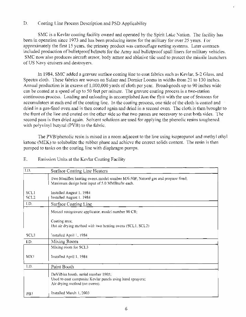
D. Coating Line Process Description and PSD Applicability
SMC is a Kevlar coating facility owned and operated by the Spirit Lake Nation. The facility has been in operation since 1973 and has been producing items for the military for over 25 years. For approximately the first 15 years. the primary product was camouflage netting systems. Later contracts included production of bulletproof helmets for the Anny and bulletproof spall liners for military vehicles. SMC now also produces aircraft am10r, body annor and ablative tile used to protect the missile launchers
of US Navy cruisers and destroyers.
In 1984, SMC added a gravure surface coating line to coat fabrics such as Kevlar, S-2 Glass. and Spectra cloth. These fabrics are woven on Sulzer and Domier Looms in widths from 21 to 130 inches. Alillual production is in excess of 1,000,000 yards of cloth per year. Broad-goods up to 90 inches wide can be coated at a speed of up to 50 feet per minute. The gravure coating process is a two-station continuous process. Loading and unloading is accomplished Aon the fly@ with the use of festoons for accumulators at each end of the coating line. In the coating process, one side of the cloth is coated and dried in a gas-tIred oven and is then coated again and dried in a second oven. The cloth is then brought to the front of the line and coated on the other side so that two passes are necessary to coat both sides. The second pass is then dried again. Solvent solutions are used for applying the phenolic resins toughened with polyvinyl butyral (PVB) to the fabric.
The PVB/phenolic resin is mixed in a room adjacent to the line using isopropanol and methyl ethyl ketone (MEK) to solubolize the rubber phase and achieve the COlTect solids content. The resin is then pumped to tanks on the coating line with diaphragm pumps.
E. Emission Units at the KevlarCoating Facility
J.D. Surface Coating Line Heaters
SCLI SCL2
Two Maniflex heating ovens, model number MX-50P; Natural gas and propane fired; Maximum design heat input of 5.0 MMBtUlbr each.
Installed August I. 1984 Installed August 1, 1984
J.D. Surface Coating Line
SCL3
Menzel rotogravure applicator, model number 90 CR;
Coating area; Hot air dlying method with two heating ovens (SCLI. SCLl)
Installed April I. 1984
I.D. Mixing Room
MXl
Mixing room for SCL3
Installed April I, 1984
I.D. Paint Booth
PBl
DeVilbiss booth, serial number 1905: Used to coat composite Kevlar panels using hand sprayers; Air drying method (no ovens).
Installed March I, 2003
6

1.D. Zone Heaters
DCLI DCL:: DCL3 DCL4
I
4 - 2.4 MMBtu/hr, natural gas fired Marshal & Williams heaters. Zone heaters for the Dip Coating Line.
Installed 1997 Installed 1997 Installed 1997 Installed 1997
Coating Line Air Make-up
6 - natural gas fired Flexair heaters for coating line air maktJ-up unit.
1.61 MMBtu/hr Installed 1981 1.56 MMBtu/hr Installed 1981 1.56 MMBtu/hr Installed 1981 1.56 MMBru/hr Installed 1981 1.56 MMBtu/hr Installed 1981 3.52 MMBhl/hr Installed 1981
Miscellaneous Heaters and Boilers
0.7 MMBtu/hr, nahlral gas fired Columbia hot water boiler. Installed 1995
I.D.
AMI AM2 AM3 AM4 AM5 AM6
1.D.
AMI PPBl 1.57 MMBtu/hr, natural gas fired Press boiler. Installed 1995 DOl 1.00 MMBtu/hr. natural gas fired draping oven. Installed 1995.
2 - natural gas fired hot water heaters for pre-treating tabric.
SJl 0.20 MMBtu/hr Installed 1988 SJ:? 0.18 MMBtu/hr Installed 1988
Tanks
18,000 gallon pressurized horizontal propane tank. Installed 2003. 6,000 gallon methyl ethyl ketone tank. Installed :2000. 6,000 gallon isopropyl alcohol tank. Installed 2000.
1.D.
PROI STl ST2
F. Potential to Emit
The majority of the emissions at the facility come from the coating line operations which include the mixing room, the surface coating line and the drying ovens. The VOC and combustion emissions from each drying oven are merged and vented through two stacks (one stack for each station/drying oven'ofthe surface coating line).
The potential to emit for each pollutant was computed using the mode with the most emissions (worst case scenario). The worst case scenario for one pollutant is not necessarily the Worst case scenario for another pollutant.
The uncontrolled potential to emit for the facility as a whole is as follows:
nitrogen oxides (NQ) 15 tpy lead - neg. carbon monoxide (CO) - 12 tpy sulfur dioxide (SOc) - neg. volatile organic compounds (YOC)- 634 tpy total hazardous air pollutants (HAPs)- 39 tpy pmticulates (PM)- I tpy largest single HAP (MethyJ Alcohol)- 26 tpy
7

V. Permitting and Construction History
SMC has operated as a minor source under the North Dakota Department of Health (NDDH) permit to operate rules. Upon promulgation of the Federal Title V Operating Pem1it Program under 40 CFR Part 71, SMC submitted an application for a Title V Operating Pem1it. During EPA review of the applicability of Federal requirements while drafting the part 71 pem1it, the applicability of the PSD rules to SMC's Kevlar coating lines was discovered. SMC began working with the Spirit Lake Tribe EPA, U.S. EPA Region 8, and SMC's technical contractors to identify and implement the PSD requirements. In this PSD pelmitting action, EPA Region 8 provided compliance assistance to bring SMC into compliance with all applicable requirements under the PSD rules. Compliance required the installation of emission control equipment on the surface coating line to control VOC emissions.
The following table provides a detailed analysis of the PTE of the facility tln-ough the progression of the various construction projects.
8

SMC Construction HistoJ)'
Estimated Potential Emissions in tons IJcr yearConstruction Time line
* Ilazardous Air Pollutant
Other HAPs Total SO, MIBK*" Methyl Phenol*I'M I.ead VOC Xylene*Emitting Units NOx CO (b - see list
~ IIAPS Alcohol* below)
1973 - 191\3 Production was solely devoted to camouflage netting systems.
1973 - Installation of Paint Booth PBI
1973 Total CUOlulatiVt' Total
191\ I Began development of helmet production.
1911 I - Installed Air Make-up Handlers
191\ I - Installed Press Boilcr
1981 Total
Cumulative Total
AMI
AM2 AM3
AM4 Ar\15
PPBI
0.00
0.00
0.00
069
067 0.67
0.67
0.67 067
·M4 4.04
o.on
0.00 0.00
0.00 0.00
0.00 0.00
0.00 0.00
0.00
0.00
1986 Began production of Spall Liners (no capital expenditure to surface coating line).
1984 - Installed Weaving
Equipment 1984 - Installed Surface Coating
Line
Note: VOC and IIAP Emissions due to solvents from the tanks, the
mixing room. and the drying o,ens
included in SCU
SCLI-drying oven
Sel.2-drying oven
SCL3-dip tanks. !lash off, mixing
room stacks (MX I)
STI- MEK Tank
ST2- IPATank
Weaving Equip
2.15
2.15
0.00
0.00
000
0.00
0.01 0.01
0.00
0.00
0.00
0.00
0.0
0.0 0.0
0.58
0.56 0.56
0.56 0.56
0.57
3.39
3.39
1.80
1.80
0.00
0.00 0.00
0.00
0.00
0.00 0.00
0.05 0.05
0.05
0.05 0.05
0.05
0.30
0.30
0.16
0.16
0.00
0.00
0.00 0.00
0.00
0.00 0.00
000 000
0.00 0.00
0.00
000
0.00
0.00
0.00
0.00
0.00
0.00 0.00
0.00
4.45
4.45
4.45
(HJ4
0.04 0.04
0.04 0.04
0.04
0.24
4.69
0.12 0.12
628.55
0.00
0.00 000
1.90
1.90 1.90
0.00 0.00
0.00 0.00 0.00
0.00
0.00 1.90
0.00
0.00
0.00
0.00
0.00
0.00
0.12
0.12 0.12
0.00 0.00
0.00
0.00 0.00
0.00
0.00
0.12
0.00
0.00
0.00
0.00
0.00 0.00
0.00
0.00 0.00
0.00
0.00 0.00 0.00
0.00
0.00
0.00
0.00
0.00
0.00 25.77
0.00 0.00
0.00
0.00
0.00 0.00
0.00 0.00
0.00 0.00
000 0.00
0.00
0.00
0.00 0.00
9.82
0.00
0.00
0.00
2150.13
2.150.13 2.150.13
OJ)] 0.01 0.010.0 I 0.010.01
0.01 0.01 0.010.01
0.01 0.01
0.06 0.06 2.210.19
0.040.04 0.04 0.04
0.98 36.57
0000.00 0.00 0.00
0.00 0.00
9

SMC Construction History
Construction Time line Estimated Potential Emissions in tons per year
* I lazard011S Air Pollutant
Emilling Units NOx SO: CO PM Lead VOC 1vllBK*a Xykne* Methyl
Alcohol*
Phenol * Other HAPs
(n - see list
below)
Total
HAPS
1984 Total 4.30 0.02 3.60 0.32 0.00 628.79
Cumulative Total 8.34 0.02 6.99 0.62 0.00 633.48 0.00 1.90
0.00 0.12
25.77 25.77
9.82
9.82 1.06 1.25
36.65 38.86
191;6 - Increased production (no
capital expenditures)
1986 - Installed Production Press SJI 0.09 0.00 0.07 0.01 000 0.00
191;6 - Installed Scouring Jig Hot Sf? 0.08 0.00 0.06 0.01 0.00 0.00
water Hcaters
1986 - Installed Air Make-up AM6 1.51 00 I 1.27 0.11 0.00 0.08
handler
0.00
0.00
0.00
0.00
0.00
0.00
0.00
0.00
0.00
0.00
0.00
0.00
0.00
0.00
OJ) I
0.00
0.00
0.03
1986 Total 1.68 0.01 1.39 0.13 0.00 0.08 Cumulative Total 10.02 0.03 8.38 0.75 0.00 63356
0.00 1.90
0.00 0.12
0.00 25.77
0.00 9.82
0.01 1.26
0.03 38.89
1990 - Installed 2 electric not emission units 0.00 0.00 0.00 0.00 0.00 0.00
Autoclaves for advanccd composite
work
0.00 0.00 0.00 0.00 0.00 0.00
1990 Total 0.00 0.00 0.00 0.00 0.00 0.00
Cumulative Total 10.02 0.03 8.38 0.75 0.00 633.56 0.00 1.90
0.00 0.12
0.00 25.77
0.00 9.82
0.00 1.26
0.00 38.89
1991 Development of dip coaling linc (I:abric clealllng prior to slirtiLce coating. No solvent based emissions).
1995 - Installed Draping Oven DOl 0.43 0.00 0.36 0.03 0.00 0.02
1995 - Installed Hot watcr Heater AI I 0.30 0.00 0.25 0.02 0.00 002
0.00
0.00
0.00
0.00
0.00
0.00
0.00
0.00
0.01 OJ)]
0.01
0.01
1995 Total 0.73 0.00 0.61 0.05 0.00 0.04
Cumulative Total 10.75 0.02 8.99 0.80 0.00 633.60
0.00 1.90
0.00 0.12
0.00 25.77
0.00 9.82
0.02
1.28
0.02
38.91
1997 Dip coating line made opcrational for \\atcrproofing (no solvent bascd emissions).
10

SMC Construction History
Construction Time line Estimated Potential Emissions in tons per year
* Hal.ardous Air Pollutanl
Ernitling Units NOx S02 CO I'M Lead VOC MIBK*" Xylene* Methyl
i\ Ieohol*
Phellol* Other I-lAPs
(b - se..: list
bdow)
Tolal
HAPS
1997 - Installed 4 drying ovens on DCLI 1.03 0.01 0.87 o.ms 0.00 0.06 Dip Coating I.ine to dry wakr DCL2 1.03 (l.() I 0.87 0.08 0.00 0.06 washed fabri<.: DCU 1.03 0.01 0.87 0.08 0.00 0.06
DCL4 1.03 0.0 I 0.87 0.08 0.00 0.06
0.00 0.00 0.00
0.00
0.00
0.00 0.00
0.00
0.00
0.00 0.00 0.00
0.00
0.00
0.00 0.00
(Ul2
0.02 0.02 0.02
0.02
0.02
0.02 002
1997 Total 4.12 0.04 3.48 0.32 0.00 0.24 CUlllulative Total 14.87 0.06 12.47 1.12 0.00 633.84
0.00 1.90
0.00 0.12
0.00 25.77
0.00
9.82
0.08 1.36
0.08
38.99
2000 Replaced und..:rground solv..:nl storage tanks.
2000 - Replae..:d 5000 gal MEK STI 000 0.00 0.00 0.00 0.00 0.00 storag..: tank
2000 - Replaced 5000 gallPA ST2 0.00 0.00 0.00 0.00 0.00 0.00 storagc tank
Assuming cmissions are th..: sam..: as
th..: original tanKS
0.00
0.00
0.00
0.00
0.00
0.00
0.00
0.00
0.00
0.00
0.00
0.00
2000 Total 0.00 0.00 0.00 0.00 0.00 0.00
Cumulative Total 14.87 0.06 12.47 I.IZ 0.00 633.84
2006 Installation of an cmission capture system and catalytic oxidizer for lhe coating line
2006 Installed ..:mission conlrol
cquipmcnt. At least 97% r..:dllction VCEI 0.00 0.00 0.00 0.00 0.00 -609.69 ofVO('s.
0.00
1.90
0.00
0.00 0.12
0.00
0.00 25.77
-25.00
0.00
9.82
-9.53
0.00
1.36
-0.95
0.00 38.99
-37.82
2006 Total 0.00 0.00 0.00 0.00 0.00 -609.69
CumUlative Total 14.87 0.06 12.47 1.12 0.00 24.15 0.00
1.90
0.00 0.12
-25.00
0.77
-9.53 0.29
-0.95
1.27
-35.47 3.52
a- MIBK is methyl isobutyl ketone. b- Other HAPs include: fom1aldehyde, toluene, ethyl benzene, 2-methylnaphthalene. 3-methy lchloranthrene, 7, J2-dimethylbenz(a)anthracene, acenaphthene, acenaphthylene, anthracene, benz(a)anthracene, benzene, benzp(a)pyrene, benzo(b)tlouranthene, benzo(g,h,i)perlene, belZo(k)tlouranthene. chrysene, dibenzo(a,h)anthracene. dichlorobenzene, tluoranthene, tluorene, hexane. indeno(J .2,3-cd)pyrene, naphthalene, phenanathrene, pyrene.
11

VI. Description of this Permitting Action
EPA evaluated the 1984 modification and the applicability of the PSD program and detemlined that PSD applied at the time the modification occulTed. for VOC emission increases. SMC submitted a PSD pemlit application on January 24. 2005, proposing to control those VOC emissions. The application was detelmined to be complete by EPA on February 25, 2005.
The purpose of this permit action is to establish emission limits and operational requirements to ensure SMC is in compliance with the National Ambient Air Quality Standards (NAAQS). the applicable PSD air quality increments, and the requirement to apply Best Available Control Technology (BACT) to miilimize emissions of air pollutants.
VII. Maximum Available Control Technologv (MACT) Requirements
40 CFR Part 63. Subpart 0000: National Emission Standards for Hazardous Air Pollutants (NESHAP) from Printing, Coating, and Dyeing of Fabrics and Other Textiles (Coatings MACT) applies
. to SMC because SMC is an existing major HAP fabric coating facility. This subpart was promulgated on May 29, 2003 (68 FR 32189) and applies to any new, reconstructed. or existing facility that is a major source and engages in printing. coating. slashing, dyeing or finishing of fabrics or other textiles.
The affected sources under the MACT provision are the collection of all web-coating equipment used to apply cleaning materials to a substrate to prepare it for coating material application. to apply coating materials to a substrate and to dry or cure the coating materials after application by exposure to heat or radiation. or to clean coating operation equipment. Also affected are all storage containers and mixing vessels in which regulated materials are stored or mixed and all manual and automated equipment and containers used for conveying waste materials generated by a coating operation. In addition. all manual and automated equipment, structures, and devices used to convey, treat, or dispose of wastewater streams or residuals are affected.
The control requirements of this rule have been considered in the BACT evaluation. The HAP emission limit options for existing affected coating sources are:
1. A 97% overall control efficiency limit (this includes both the capture efficiency and the add-on control efficiency): or
'1 0.12 lb organic HAP per lb of coating solids used during each monthly compliance period; or
3. If using an oxidizer to control organic HAP emissions, operate the oxidizer such that an outlet organic HAP concentration of no greater than 20 parts per million by volume (ppmv) on a dry basis is achieved and the efficiency of the capture system is 100%.
Vlll. New Source Perfomlance Standard (NSPS) Requirements
Standards of Perfomlance for Polymeric Coating of Supporting Substrate Facilities at 40 CFR part 60, subpart VVV, applies to any affected facility for which construction, modification, or recOl~struction
begins after April 30, 1987. This rule applies to web coating facilities that apply elastomer or other polymeric material onto a supporting substrate. Typical substrates include: woven, knit. and non-woven textiles, fiberglass, yam. and cord. Examples of polymeric coatings are natural and synthetic rubber,
12
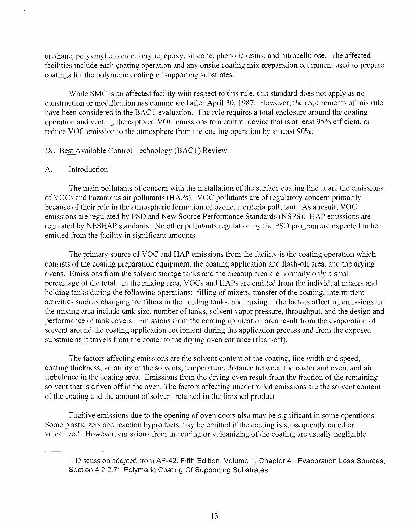
urethane. polyvinyl chloride, acrylic, epoxy, silicone, phenolic resins, and nitrocellulose. The affected facilities include each coating operation and any onsite coating mix preparation equipment used to prepare coatings for the polymeric coating of supporting substrates.
While SMC is an affected facility with respect to this rule, this standard does not apply as no construction or modification has commenced after April 30, 1987. However, the requirements ofthis rule have been considered in the BACT evaluation. The rule requires a total enclosure around the coating operation and venting the captured VOC emissions to a control device that is at least 95% etlicient, or reduce VOC emission to the atmosphere from the coating operation by at least 90%.
IX. Best Available Control Technology (BACT) Review
A. Introduction1
The main pollutants of concern with the installation of the surface coating line at are the emissions ofVOCs and hazardous air pollutants (HAPs). VOC pollutants are of regulatory concem primarily because of their role in the atmospheric formation of ozone, a criteria pollutant. As a result, VOC emissions are regulated by PSD and New Source Perfonnance Standards (NSPS). HAP emissions are regulated by NESHAP standards. No other pollutants regulation by the PSD program are expected to be emitted from the facility in significant amounts.
The primary source of VOC and HAP emissions from the facility is the coating operation which consists of the coating preparation equipment, the coating application and t1ash-off area, and the drying ovens. Emissions from the solvent storage tanks and the cleanup area are nonnally only a small percentage of the total. In the mixing area, VOCs and HAPs are emitted from the individual mixers and holding tanks during the following operations: tilling of mixers, transfer of the coating, intenllittent activities such as changing the filters in the holding tanks, and mixing. The factors affecting emissions in the mixing area include tank size, number of tanks, solvent vapor pressure, throughput, and the design and performance of tank covers. Emissions from the coating application area result from the evaporation of solvent around the coating application equipment during the application process and from the exposed substrate as it travels from the coater to the drying oven entrance Wash-off).
The factors affecting emissions are the solvent content of the coating, line width and speed, coating thickness, volatility of the solvents, temperature, distance between the coater and oven, and air turbulence in the coating area. Emissions from the drying oven result from the fraction of the remaining solvent that is driven otT in the oven. The factors atTecting uncontrolled emissions are the solvent content of the coating and the amount of solvent retained in the finished product.
Fugitive emissions due to the opening of oven doors also may be significant in some operations. Some plasticizers and reaction byproducts may be emitted if the coating is subsequently cured or vulcanized. However, emissions from the curing or vulcanizing of the coating are usually negligible
1 Discussion adapted from AP-42, Fifth Edition, Volume 1, Chapter 4: Evaporation Loss Sources, Section 4.2.2.7: Polymeric Coating Of Supporting Substrates
13

compared to the total emissions from the operation. Solvent type and quantity are the common factors affecting emissions from all the operations in a polymeric coating facility. The rate of evaporation or drying is dependent upon solvent vapor pressure at a given temperature and concentration. The most commonly used organic solvents are toluene, dimethyl fonnamide (DHF), acetone, methyl ethyl ketone (MEK), isopropyl alcohol, xylene, and ethyl acetate. Factors atIecting solvent selection are cost, solvency, toxicity, availability, desired rate of evaporation, ease of use after solvent recovery, and compatibility with solvent recovery equipment SMC solvent selection is also affected by military specitications on the products it produces.
BACT will be employed on the coating operations for VOC emissions. However, the control technologies used to control emissions ofVOCs are generally the same type of technology used to control toxic air pollutant emissions. Therefore, the application of BACT for VOC emissions will also serve to meet the requirements of the Coatings MACT.
B. BACT Analysis
Pursuant to '52.21 (j), a new major stationary source shall apply best available control teclmo10gy for each pollutant subject to regulation under the Clean Air Act (CAA) that it would have the potential to emit in significant amounts. The requirement applies to each proposed emissions unit at which a net emissions increase in the pollutant would occur as a result of a physical change or change in the method of operation in the unit In addition, a major stationary source or major modification shall meet each applicable emissions limitation under an applicable implementation plan and each applicable Federal emissions standard and standard of performance under 40 CFR parts 60 and 61.
The definition of BACT at '52.21 (b)(12) states, in part, that BACT is an emissions limitation (including a visible emission standard) based on the maximum degree of reduction for each pollutant subject to regulation under the CAA which would be emitted from any proposed major stationary SOlUTe or major modification which the administrator, on a case-by-case basis, taking into account energy, environmental, and economic impacts and other costs, determines is achievable for such source or modification through application of production processes or available methods, systems, and techniques, including fuel cleaning or treatment or ilmovative fuel combustion techniques for control of such pollutant
On December 1, 1987, the EPA Assistant Administrator for Air and Radiation issued a memorandum that implemented program initiatives designed to improve the effectiveness of the NSR program. Among those initiatives was the Atop-down@ method for detennining BACT. This methodology was incorporated into EPA=s 1990 Draft New Source Review (NSR) Workshop Manual. The following sub-sections contain the required review, analysis, and detennination of BACT using the guidelines from Chapter B of EPA=s NSR Workshop Manual. The steps used are as follows:
1dentify all control technologies; Eliminate technically infeasible options; Rank remaining control technologies by control effectiveness; Evaluate most effective controls and document results; and Select BACT
14

C. Step One: Identify All Control Technologies
A control system for evaporative emissions from coating operations consists of two components: a capture device and a control device. A capture device is used to contain emissions ti'om a process operation and direct them to a stack or to a control device. Covers, vents, hoods, and partial and total enclosures are alternative capture devices used on coating preparation equipment. Hoods and partial and total enclosures are typical capture devices for use in the coating application area. A drying oven can be considered a capture device because it both contains and directs VOC emissions from the process.
A search of EPA==s RACT/BACT/LAER Clearinghouse was conducted to identifY all available VOC control technologies for both fabric coating operations, specifically, and all other coating operations in general. In addition, the NESHAP and NSPS requirements for coating operations were reviewed for control technology requirements. Finally, AP-42, Fifth Edition, Volume 1, Chapter 4: Evaporation Loss Sources, Section 4.2.2.7: Polymeric Coating Of Supporting Substrates was consulted to gain an understanding of the control options available. The following control options were identified:
Emission Capture Device with Carbon Adsorption, 95% overall control efficiency; Emission Capture Device with Condenser, 95% overall control efticiency; Emission Capture Device with Them1al oxidation, 95 - 98% overall control efficiency; and Low VOC Coating and/or low emitting application technique, 85-100% overall control efficiency.
Carbon adsorption units use activated carbon to adsorb VOCs from a gas stream; the VOCs are later recovered hom the carbon. Two types of carbon adsorbers are available: fixed-bed and fluidized bed. Fixed-bed carbon adsorbers are designed with a steam-stripping technique to recover the VOC material and regenerate the activated carbon. The fluidized-bed units used in this industry are designed to use nitrogen for VOC vapor recovery and carbon regeneration. Both types achieve typical VOC control efticiencies of 95 percent when properly designed, operated. and maintained.
Condensation units control VOC emissions by cooling the solvent-laden gas to the dew pointofthe solvent(s) and collecting the droplets. There are two condenser designs commercially available: nitrogen (inert gas) atmosphere, and air atmosphere. These systems differ in the design and operation of the drying oven (i. e., use of nitrogen or air in the oven) and in the method of cooling the solvent laden air (i. e., liquified nitrogen or refrigeration). Both design types can achieve VOC control efficiencies of 95 percent.
Incinerators control VOC emissions through oxidation of the organic compounds into carbon dioxide and water. Incinerators used to control VOC emissions may be of thermal or catalytic design and may use primary or secondary heat recovery to reduce fuel costs. Them1al incinerators operate at approximately 890°C (l600°F) to ensure oxidation of the organic compounds. Catalytic incinerators operate in the rage of 325°C to 430°C (600 to 800°F) while using a catalyst to achieve comparable oxidation of VOCs. Both design types achieve a typical VOC control efficiency of 98 percent.
Low VOC coatings and/or low emitting application techniques are a pollution prevention approach to mitigating VOC emissions. Pollution prevention is a process or raw material change that reduces the quantity or toxicity of an emission or waste at the point of generation. The raw materials generally used in fabric coating industry include fabric substrates, solvents. resins. and other specialty chemicals used to
15

impart a desired property to the coated fabric. Low emitting application teclmiques would include teclmiques that reduce the amount of chemical overspray and/or chemical volatilization, such as dipping rather than spraying the fabric.
Supplemental to all VOC control options is the utilization of tightly fitting covers. Tightly fitting covers control VOC emissions from mixing vessels by reducing evaporative losses. Airtight covers can be fitted with conservation vents to avoid excessive internal pressure or vacuum. The parameters affecting the efficiency of these controls are solvent vapor pressure, cyclic temperature change, tank size, throughput and the pressure and vacuum settings on the conservation vents. A good system of tightly fitted covers on mixing area vessels is estimated to reduce emissions by approximately 40 percent Control efficiencies 01'95 or 98 percent can be obtained by directing the captured VOCs to an adsorber, condenser, or incinerator.
D. Step Two: Eliminate Teclmically Infeasible Options
SMC==s coated fabric products must meet strict military specifications with regard to coating forn1Ulations and application techniques and do not allow for low VOC coatings. Therefore, the Alow VOC coating and/or low emitting application teclmiques@ control alternative is not technically feasible for SMC. This option will not be considered further in this BACT analysis.
E. Step Three: Rank Remaining Control Technologies by Control Eflectiveness
The remaining control technologies, ranked by control eflectiveness, are as follows:
Emission Capture Device with Thennal/Catalytic Oxidation, 95 - 98(% overall control efficiency; Emission Capture Device with Carbon Adsorption, 95% overall control efficiency; and Emission Capture Device with Condenser, 95% overall control efficiency.
F. Step Four: Evaluate the Most Effective Controls and Document Results
According to the October 1990 Draft New Source Review Workshop Manual, an applicant who has proposed the top control alternative need not provide cost and other detailed infoJ111ation in regard to the other control options. However, the control option chosen should still be reviewed for collateral environmental impacts. SMC has proposed the top control alternative of an emission capture device with catalytic oxidation. In addition, SMC has agreed to follow the work practice. testing, monitoring, recordkeeping, repo11ing, and compliance requirements of the Coatings MACT as part of its BACT
. proposal.
SMC has proposed to reduce VOC and HAP emissions to the atmosphere by achieving at least a 97% organic HAP overall control efficiency. The Coatings MACT standard of achieving a 97% overall control efficiency ofAVOC@ HAPs is consistent with the top control alternative listed in the RBLC. Therefore, SMC proposes the Coatings MACT standard as BACT for controlling VOC emissions from the coating operations.
Non-air environmental and energy impacts could result from the installation of the add-on control. Sources that currently do not employ any air control system and that install catalytic oxidizers will
16

increase solid waste generation. However, the catalysts can be regenerated by the manufacturer for reuse. Energy requirements will include electricity to collect and treat ventilation air and natural gas to provide supplemental fuel for the stable operation of the oxidizer.
G. Step Five: Select BACT2
The top control altemative, emission capture with catalytic oxidation, has been proposed as BACT for the entire coating operation. An overall control efficiency of 97% includes the capture of emissions from the solvent storage areas, the mixing areas, the coating application areas, m1d the drying ovens. The captured vapors would be directed through two stacks to a catalytic oxidizer.
Capture techniques in the storage and mixing areas would include covers, vents, and hoods. Hoods and pmiial and total enclosures would be used in the coating application areas, flash-off areas, and to capture fugitive emissions from the opening and closing of the drying oven doors.
The Coatings MACT establishes two distinct emission standards. The overall control efficiency requirement for existing sources is 97%, and the overall control efficiency requirement for new sources is 98'%. The main ditIerence between the two requirements is the VOC capture efficiency requirement. While a capture efliciency of 100% is required for new facilities, a lower capture efficiency of 99% is required for existing sources.
Existing facilities have monetary and design disadvantages over new facilities when installing VOC capture systems. Capture systems on existing facilities must be retrofitted around the existing solvent storage areas, mixing areas, coating application areas, drying ovens, building, and support structures. The U.S. EPA Office of Air Quality Planning and Standards observed, in the June 2002 Technical Support Document: Printing, Coating, and pyeing o.lFabrics and Other Textiles Proposed NESHAP, EPA--I53/R-02-01O, that the incremental emission reductions that would be achieved with the
. 1% additional capture efficiency are not supported by the additional cost that existing facilities would incur. EPA Region 8 agrees that the incremental cost for SMC may be prohibitive. In addition, until testing is conducted, SMC Calmot verity if 100% capture is teclmically feasible.
The MACT standard, which the proposed control equipment will meet, was selected by EPA expressly on the basis of representing the top three best perfonning coating facilities nationwide. Therefore, EPA agrees that BACT for this action is emission capture devices and catalytic oxidation with a 97% overall control efticiency. Since the top BACT is proposed, a full top-down evaluation of altemate systems in not required.
SMC shall commit to the use of the proposed emissions capture system for the entire coating operation, including the capture of emissions from the solvent storage areas, the mixing areas, the coating application areas, and the drying ovens and destruction of the emissions with a catalytic oxidizer. In an effort to maximize control ofVOC emissions, SMC proposes to design the mixing room ventilation system so that it can be vented to the oxidizer when the oxidizer is operating. It is plmmed to have the oxidizer operating at all times the coating line operates. However, whenever the coating line is ofT, the
2The discussion of capture efficiency summarizes the discussion provided by Air Sciences, Inc., in the SMC PSD application.
17

oxidizer is also shut down because the VOC emissions from the coating line provide the majority of the fuel for maintaining the oxidizer operating temperature. Therefore, as part of BACT, SMC has proposed a control strategy work plan in addition to accepting conditions specifying the level of control, including the associated operation, maintenance, monitoring, recordkeeping and repOliing requirements, as specified in the Coatings MACT.
NOTE: While the Coatings MACT provides flexible options for complying with the emission standard for hazardous air pollutants, that t1exibility has not been incorporated into this PSD permit for the control ofVOC emissions. SMC was asked to select a single option for controlling VOCs and demonstrating compliance with this PSD pemlit. In addition, unlike MACT standards promulgated at 40 CFR part 63, PSD pennit limits apply at all times including during periods of start-up, shut-down and malfunctions.
X. SMC Control Strategy
The SMC sources ofVOC emissions atIected by the Coatings MACT are the coating line (SCL3) and the coating line drying ovens (SCLl and SCL2). Other activities affected by the Coatings MACT, which may generate small amounts ofVOC emissions, include the outdoor solvent storage tanks, the mixing room, mixing vessels and coating storage tanks, pipes used to convey coatings and solvents to the coating line, periodic cleaning of the coating line, and drums stored in the chemical room. These VOC sources are the same sources that are subject to the PSD requirements that were triggered in 1984.
A. VOC Controls and Work Practices
To control VOC emissions from SCL1, SCL2, and SCL3, SMC shall install a pemlanent total enclosure capture system (capture system) and catalytic oxidizer (oxidizer). The capture system shall enclose the areas where coating is applied to the substrate, and the captured VOC emissions shall be ducted directly into the dryers. The dryers shall in tum be ducted directly to the oxidizer. The overall VOC destruction efficiency of the capture system and oxidizer shall be at least 97% as required by §63.429l(a)(4).
VOC emissions from the tanks, vessels, drums, and conveying and cleaning operations shall be minimized according to a "work practice plan" required by §63.4293(b). The work practice plan is discussed in section X.C of this document.
Pursuant to §63.4350(b), SMC shall install the emission capture system, oxidizer, and a continuous parameter monitoring system (ePMS) by May 29, 2006, SMC has already developed a work practice plan, submitted it to EPA (submitted as an addendum to the PSD application on September L 2005) and has plans to implement it by the compliance date of May 29, 2006. In addition, SMC shall establish operating limits and a CPMS as required by 63.4364(e) by January 24, 2007, and update it annually pursuant to 63.4364(e)(5). The operating limits and CPMS shall be established based on results of the initial perfol1nance test.
B. Emission Capture System and Oxidizer Operating Requirements
SMC shall be subject to the following requirements for operating the oxidizer pursuant to §63 .4292(b):
18

1. A minimum catalyst bed inlet temperature (3-hour average) established during the perfonnance test in accordance with §63.4363(b)(1) or (3), and
2. A minimum temperature difference across the catalyst bed established during the perfom1ance test per §63 .4363(b)(2), or operation according to a "site-specific inspection and maintenance plan" for the oxidizer developed in accordance with §63.4363(b)(4).
SMC shall be subject to the following requirements for operating the emission capture system pursuant to §63.4364 (e):
1. Submit a site-specific monitoring plan to the EPA that identifies operating parameters to be monitored. The monitoring plan must identify the operating parameters to be monitored, provide a justification for the selection of the parameters, and identify the monitoring procedures;
2. Specify in the monitoring plan the operating parameter value or range of values that demonstrate compliance with emission limit requirements of this permit; and
3. Update the monitoring plan annually.
C. Work Practice Plan
1. The following units and operations shall be subject to the work practice plan:
0.) The outdoor solvent storage tanks (STI and ST2); (ii.) The mixing room mixing vessels and coating storage tanks (part of SCL3); (iii.) Pipes used to convey coating and solvents: (iv.) Periodic cleaning of the coating line: and (v.) Drums stored in the chemical room.
2. The following provisions of the Coatings MACT shall be included in the work practice plan pursuant to §§63.4293(b)(1) through (5):
(i.) All volatile organic material and waste materials shall be stored in closed containers;
(ii.) Spills of volatile organic materials and waste materials shall be minimized: (iii.) Volatile organic materials and waste materials shall be conveyed from one location
to another in closed containers or pipes; (iv.) The mixing vessels shall be closed except when adding, removing, or mixing the
contents: and (v.) Emissions shall be minimized during cleaning of the coating, storage, mixing, and
conveying equipment.
3. Design the mixing room ventilation system so that emissions can be vented to the oxidizer when the coating line and oxidizer are operating.
19
4. Operate the oxidizer at all times the coating line operates.
5. Make every effort to conduct all mixing activities during times when the coating line and oxidizer are operating.
6. Comply with the bypass-line requirements of §63.4352(d) and §63.4364(b) during cleaning operations. VOC emissions from cleaning operations (running solvent through the tanks, pipes, and coating line applicators) shall be vented to the bypass stack to allow for ventilation. To meet the by-pass line requirements, SMC shall:
(i.) Monitor or secure the valve or closure mechanism controlling the bypass line in a non-diverting position in such a way that the valve or closure mechanism cannot be opened without creating a record that the valve was opened. The method used to mOliitor or secure the valve or closure mechanism must meet one of the following requirements pursuant to §63.4364(b):
(a.) Flow control position indicator; (b.) Car-seal or lock-and-key valve closures; (c.) Valve closure continuous monitoring; or (d.) Automatic shutdown system;
(ii.) Establish the method used to monitor or secure the valve or closure mechanism on the by-pass line by the initial perfonnance test date and submit the infom1ation on the method and the CPMS to be used in conjunction with the operation of the bypass line with the perfoD11ance test results;
(iii.) Maintain the monitoring and/or closure mechanism in proper working order including, but not limited to, maintaining necessary parts for routine repairs of the monitoring equipment;
(iv.) Record the results of each inspection, calibration, and validation check of the monitor system, closure mechanism and CPMS;
(v.) Record when any bypass line is opened. The record shall be made contemporaneously with the opening of the line. The record shall provide a description of why the bypass line was opened and the length of time it remained open. The records shall be reported to EPA in the semimmual compliance reports;
(a.) Report the by-pass line opening as a deviation anytime the bypass line is opened and emissions are diverted to the atmosphere while the coating line is rulming; and
(b.) Calculate deviation emissions that occur while the coating line is operating and the bypass line is open as if the coating line were uncontrolled for that period of time.
20

D. Perfonnance Testing and Establishing Operating Limits
Upon completion of the installation and start-up of the emission capture systems, catalytic oxidizer by-pass system, and continuous parameter monitors, SMC shall be required to conduct perfon11ance tests for the new systems to ensure proper operating parameters are established and assuring that the system can meet the permitted level ofVOC emission control.
SMC shall be required to conduct perfonnance tests to verify compliance with the proposed limits of this pennit using the following test methods pursuant to §63.4362:
• Method 1 or 1A of appendix A to 40 CFR part 60, as appropriate to select sampling sites c;md velocity traverse points;
• Method 2, 2A, 2C, 2D, 2F, or 2G of appendix A to 40 CFR part 60, as appropriate to measure gas volumetric flow rate;
• Method 3, 3A, or 3B of appendix A to 40 CFR part 60, as appropriate, for gas analysis to detenl1ine dry molecular weight;
• Method 4 of appendix A to 40 CFR part 60 to determine stack gas moisture; and • Method 25 or 25A of appendix A to 40 CFR part 60 to measure the volatile organic matter
concentration as carbon at the inlet and outlet of the add-on control device simultaneously; Method 25 if the total gaseous organic concentration as carbon is expected to be more than 50 parts per million (ppm) at the control device outlet and Method 25A if the total gaseous organic concentration as carbon is expected to be 50 ppm or less at the control device outlet.
In addition, SMC shall be required to establish the following control device operating parameters during the perfom1ance tests pursuant to §63 .4363:
• The minimum operating temperature at the inlet to the catalytic oxidizer and the temperature difference across the catalyst bed maintained during the performance test or develop and implement an inspection and maintenance plan for the catalytic oxidizer to include aIU1Ual sampling and analysis of the catalyst activity, monthly inspection of the oxidizer system, and mIDual internal and monthly external visual inspection of the catalyst bed; and
• 100 percent capture efficiency of the emission capture system using Method 204 to appendix M of 40 CFR part 51.
XI. Emission Summary (based on applied BACT)
SMC conducted stack testing on the two existing exhaust stacks associated with the coating line and its two drying ovens. Testing was conducted in accordance with the following test methods referenced in 40 CFR part 60, appendix A:
Method 1 - Sample and Velocity Traverses for Stationary Sources; Method:2 - Determination of Stack Gas Ve10city and Volumetric Flow Rate; Method 3 - Gas Analysis for Detennination of Dry Molecular Weight. and Method 18 - Measurement of Gaseous Organic Compound Emissions by Gas Chromatography.
21
The purpose of the stack testing was to gather data to inforn1 the BACT detennination and to infonn the design and engineering of the selected VOC/HAP control system. The results indicated an average VOC emission rate for the facility of 423.6 pounds ofVOCs per hour. With a 97% overall control efficiency, the VOC emissions would be approximately 12.7 Ibs per hour. At this hourly rate of controlled emissions, the annual PTE, based on 8760 hours of operation per year, of VOC emissions would be approximately 56 tons per year.
XII. Air Quality Analysis
A. Ambient Impact Analysis
An applicant for a PSD pennit is required to conduct an air quality analysis of the ambient impacts associated with the construction and operation of the proposed new or modified source. The main purpose of the air quality analysis is to demonstrate that criteria pollutant emissions emitted from the proposed source shall not cause or contribute to a violation of any applicable NAAQS or PSD increment. The NAAQS are maximum concentration "ceilings" measured in tenns of the total concentration of a pollutant in the atmosphere. For a new or modified source, compliance with any NAAQS is based upon the total estimated air quality, which is the sum of the ambient estimates resulting from existing sources of air pollution and the modeled ambient impact caused by the applicant's proposed emissions increase and associated growth. A PSD increment is the maximum allowable increase in concentration that is allowed to occur above a baseline concentration for a pollutant. The baseline concentration is defined for each pollutant and is the ambient concentration existing at the time that the first complete PSD pennit application atIecting the area is submitted. Significant deterioration is said to occur when the amount of new pollution would exceed the applicable PSD increment. PSD increments exist for pmiiculate matter, sulfur dioxide, and nitrogen dioxide and levels, in llg/m3
, have been established for Class I, Class II, and Class III areas.
40 CFR 52.21(m)(1) requires that the PSD application contain pre-construction ambient air quality data for each pollutant emitted in significant amounts for purposes of detennining whether emissions of each pollutant from the major stationary source would cause or contribute to a violation of a standard. In addition, 40 CFR 52.21(111)(2) requires that post-construction ambient monitoring be conducted as the Administrator deems necessary to detern1ine the effect of emissions from the major stationary source on air quality. The Administrator may exempt a stationary sources or modification from the requirements of ambient monitoring if the net emissions increase from the modified source would cause less than the following amounts:
Carbon monoxide - 575 llg/m3, 8-hour average;
Nitrogen dioxide - 14 ~lg/m3, annual average; Particulate matter - 10 llg/m3 of PM] 0, 24-hour average; Sulfur dioxide - 13 llg/m3
, 24-hour average; and Ozone - No de minimus air quality is provide for ozone.
The only pollutant of concern with this project are VOCs. VOC pollutants are of regulatory concern primarily because of their role in the atmospheric fOlmation of ozone, a criteria pollutm1t. Any net increase of 100 tpy or more of VOCs would be required to perfonn an ambient impact analysis for ozone including the gathering of mnbient air quality data. However, this is an emissions reduction project resulting in a decrease of over 600 tpy ofVOCs and post-project potential emissions of approximately 24
22

tpy, well below the 100 tpy threshold. Therefore, no ambient impact analysis or pre- or post-ambient air quality monitoring shall be required for this project.
B. Additional Impacts Analysis
40 CFR 52.21(0) requires that owners and/or operators of proposed sources provide an analysis of the impairment to visibility, soils and vegetation that would occur as a result of the source or modification and general commerciaL residential, industrial and other growth associated with the source or modification.
The addition of the coating line and the subsequent emissions reduction project are not believed to have caused any significant impairment to visibility, soils, or vegetation. Emissions ofNOx, S02, CO and PM are all well below the PSD significant emission rate thresholds, and VOC emissions after controls are below the significant modeling level. Therefore, there is no reasonable expectation that visibility soils or vegetation would be impaired.
The impact for commercial, residential or industrial growth associated with the coating line is also expected to be minimal. SMC employs approximately 250 people. Most of the employees were residents of the local area prior to the addition of the new coating line and no new employees are expected to be added due to this emission reduction project.
C. Class I Visibility Monitoring
The emissions of the visibility impairing pollutants NOx, S02, and PM are low and the nearest Class I area, Lost Wood National Wildlife Refuge, is over 250 kilometers from the SMC facility. Impacts to visibility in any Class I are expected to be negligible, and no Class I visibility analysis or monitoring is warranted.
XIII. Endangered Species Act (ESA)
Section 7 of the ESA requires Federal agencies to ensure, in consultation with the U.S. Fish and Wildlife Service (FWS), that their actions are not likely to jeopardize the continued existence of federallylisted threatened or endangered species or result in the destruction or adverse moditication of designated critical habitat of such species.
On September 7, 2004, a letter was mailed by Air Sciences, Inc., to the FWS outlining the proposed Federal action - issuance of a construction pemlit under 40 CFR 52.21 for the existing SMC fabric coating facility. On September 15,2004, the FWS responded that the project shall have no significant impact on tlsh and wildlife, and that no endangered or threatened species are known to occupy the proj ect area. EPA has reviewed and concurs with the Air Sciences evaluation and the FWS tindings.
23