Embed Size (px)
Citation preview

EQASOP-GW4 Region 1 Low-Stress
(Low-Flow) SOP Revision Number: 4 Date: July 30, 1996
Revised: September 19, 2017 Page 1 of 30
U.S. ENVIRONMENTAL PROTECTION AGENCY REGION I
LOW STRESS (low flow) PURGING AND SAMPLING PROCEDURE FOR THE COLLECTION OF GROUNDWATER SAMPLES FROM MONITORING WELLS
Quality Assurance Unit U.S. Environmental Protection Agency – Region 1
11 Technology Drive North Chelmsford, MA 01863
The controlled version of this document is the electronic version viewed on-line only. If this is a printed copy of the document, it is an uncontrolled version and may or may not be the version currently in use. This document contains direction developed solely to provide guidance to U.S. Environmental Protection Agency (EPA) personnel. EPA retains the discretion to adopt approaches that differ from these procedures on a case-by-case basis. The procedures set forth do not create any rights, substantive or procedural, enforceable at law by party to litigation with EPA or the United States. Prepared by:__________________________________ ____________ (Robert Reinhart, Quality Assurance Unit) Date Approved by:__________________________________ ____________ (John Smaldone, Quality Assurance Unit) Date

EQASOP-GW4 Region 1 Low-Stress
(Low-Flow) SOP Revision Number: 4 Date: July 30, 1996
Revised: September 19, 2017 Page 2 of 30
Revision Page Date Rev
# Summary of changes Sections
7/30/96 1 Finalized 01/19/10 2 Updated All sections 3/23/17 3 Updated All sections 9/20/17 4 Updated Section 7.0
EQASOP-GW4 Region 1 Low-Stress
(Low-Flow) SOP Revision Number: 4 Date: July 30, 1996
Revised: September 19, 2017 Page 3 of 30
Table of Contents 1.0 USE OF TERMS.................................................................................................................. 4
2.0 SCOPE & APPLICATION .................................................................................................. 5
3.0 BACKGROUND FOR IMPLEMENTATION .................................................................... 6
4.0 HEALTH & SAFETY ......................................................................................................... 7
5.0 CAUTIONS ......................................................................................................................... 7
6.0 PERSONNEL QUALIFICATIONS .................................................................................... 9
7.0 EQUIPMENT AND SUPPLIES .......................................................................................... 9
8.0 EQUIPMENT/INSTRUMENT CALIBRATION ............................................................. 13
9.0 PRELIMINARY SITE ACTIVITIES (as applicable) ....................................................... 13
10.0 PURGING AND SAMPLING PROCEDURE .................................................................. 14
11.0 DECONTAMINATION .................................................................................................... 19
12.0 FIELD QUALITY CONTROL.......................................................................................... 21
13.0 FIELD LOGBOOK ............................................................................................................ 21
14.0 DATA REPORT ................................................................................................................ 22
15.0 REFERENCES .................................................................................................................. 22
APPENDIX A ............................................................................................................................... 24
PERISTALTIC PUMPS ............................................................................................................ 24
APPENDIX B ............................................................................................................................... 25
SUMMARY OF SAMPLING INSTRUCTIONS ..................................................................... 25
Low-Flow Setup Diagram ......................................................................................................... 29
APPENDIX C ............................................................................................................................... 30
WELL PURGING-FIELD WATER QUALITY MEASUREMENTS FORM ........................ 30
EQASOP-GW4 Region 1 Low-Stress
(Low-Flow) SOP Revision Number: 4 Date: July 30, 1996
Revised: September 19, 2017 Page 4 of 30
1.0 USE OF TERMS Equipment blank: The equipment blank shall include the pump and the pump's tubing. If tubing is dedicated to the well, the equipment blank needs only to include the pump in subsequent sampling rounds. If the pump and tubing are dedicated to the well, the equipment blank is collected prior to its placement in the well. If the pump and tubing will be used to sample multiple wells, the equipment blank is normally collected after sampling from contaminated wells and not after background wells. Field duplicates: Field duplicates are collected to determine precision of the sampling procedure. For this procedure, collect duplicate for each analyte group in consecutive order (VOC original, VOC duplicate, SVOC original, SVOC duplicate, etc.). Indicator field parameters: This SOP uses field measurements of turbidity, dissolved oxygen, specific conductance, temperature, pH, and oxidation/reduction potential (ORP) as indicators of when purging operations are sufficient and sample collection may begin. Matrix Spike/Matrix Spike Duplicates: Used by the laboratory in its quality assurance program. Consult the laboratory for the sample volume to be collected. Potentiometric Surface: The level to which water rises in a tightly cased well constructed in a confined aquifer. In an unconfined aquifer, the potentiometric surface is the water table. QAPP: Quality Assurance Project Plan SAP: Sampling and Analysis Plan SOP: Standard operating procedure Stabilization: A condition that is achieved when all indicator field parameter measurements are sufficiently stable (as described in the “Monitoring Indicator Field Parameters” section) to allow sample collection to begin. Temperature blank: A temperature blank is added to each sample cooler. The blank is measured upon receipt at the laboratory to assess whether the samples were properly cooled during transit. Trip blank (VOCs): Trip blank is a sample of analyte-free water taken to the sampling site and returned to the laboratory. The trip blanks (one pair) are added to each sample cooler that contains VOC samples.
EQASOP-GW4 Region 1 Low-Stress
(Low-Flow) SOP Revision Number: 4 Date: July 30, 1996
Revised: September 19, 2017 Page 5 of 30
2.0 SCOPE & APPLICATION The goal of this groundwater sampling procedure is to collect water samples that reflect the total mobile organic and inorganic loads (dissolved and colloidal sized fractions) transported through the subsurface under ambient flow conditions, with minimal physical and chemical alterations from sampling operations. This standard operating procedure (SOP) for collecting groundwater samples will help ensure that the project’s data quality objectives (DQOs) are met under certain low-flow conditions. The SOP emphasizes the need to minimize hydraulic stress at the well-aquifer interface by maintaining low water-level drawdowns, and by using low pumping rates during purging and sampling operations. Indicator field parameters (e.g., dissolved oxygen, pH, etc.) are monitored during purging in order to determine when sample collection may begin. Samples properly collected using this SOP are suitable for analysis of groundwater contaminants (volatile and semi-volatile organic analytes, dissolved gases, pesticides, PCBs, metals and other inorganics), or naturally occurring analytes. This SOP is based on Puls, and Barcelona (1996). This procedure is designed for monitoring wells with an inside diameter (1.5-inches or greater) that can accommodate a positive lift pump with a screen length or open interval ten feet or less and with a water level above the top of the screen or open interval (Hereafter, the “screen or open interval” will be referred to only as “screen interval”). This SOP is not applicable to other well-sampling conditions. While the use of dedicated sampling equipment is not mandatory, dedicated pumps and tubing can reduce sampling costs significantly by streamlining sampling activities and thereby reducing the overall field costs. The goal of this procedure is to emphasize the need for consistency in deploying and operating equipment while purging and sampling monitoring wells during each sampling event. This will help to minimize sampling variability. This procedure describes a general framework for groundwater sampling. Other site specific information (hydrogeological context, conceptual site model (CSM), DQOs, etc.) coupled with systematic planning must be added to the procedure in order to develop an appropriate site specific SAP/QAPP. In addition, the site specific SAP/QAPP must identify the specific equipment that will be used to collect the groundwater samples. This procedure does not address the collection of water or free product samples from wells containing free phase LNAPLs and/or DNAPLs (light or dense non-aqueous phase

EQASOP-GW4 Region 1 Low-Stress
(Low-Flow) SOP Revision Number: 4 Date: July 30, 1996
Revised: September 19, 2017 Page 6 of 30
liquids). For this type of situation, the reader may wish to check: Cohen, and Mercer (1993) or other pertinent documents. This SOP is to be used when collecting groundwater samples from monitoring wells at all Superfund, Federal Facility and RCRA sites in Region 1 under the conditions described herein. Request for modification of this SOP, in order to better address specific situations at individual wells, must include adequate technical justification for proposed changes. All changes and modifications must be approved and included in a revised SAP/QAPP before implementation in field. 3.0 BACKGROUND FOR IMPLEMENTATION It is expected that the monitoring well screen has been properly located (both laterally and vertically) to intercept existing contaminant plume(s) or along flow paths of potential contaminant migration. Problems with inappropriate monitoring well placement or faulty/improper well installation cannot be overcome by even the best water sampling procedures. This SOP presumes that the analytes of interest are moving (or will potentially move) primarily through the more permeable zones intercepted by the screen interval. Proper well construction, development, and operation and maintenance cannot be overemphasized. The use of installation techniques that are appropriate to the hydrogeologic setting of the site often prevent "problem well" situations from occurring. During well development, or redevelopment, tests should be conducted to determine the hydraulic characteristics of the monitoring well. The data can then be used to set the purging/sampling rate, and provide a baseline for evaluating changes in well performance and the potential need for well rehabilitation. Note: if this installation data or well history (construction and sampling) is not available or discoverable, for all wells to be sampled, efforts to build a sampling history should commence with the next sampling event. The pump intake should be located within the screen interval and at a depth that will remain under water at all times. It is recommended that the intake depth and pumping rate remain the same for all sampling events. The mid-point or the lowest historical midpoint of the saturated screen length is often used as the location of the pump intake. For new wells, or for wells without pump intake depth information, the site’s SAP/QAPP must provide clear reasons and instructions on how the pump intake depth(s) will be selected, and reason(s) for the depth(s) selected. If the depths to top and bottom of the well screen are not known, the SAP/QAPP will need to describe how the sampling depth will be determined and how the data can be used. Stabilization of indicator field parameters is used to indicate that conditions are suitable for sampling to begin. Achievement of turbidity levels of less than 5 NTU, and stable drawdowns of less than 0.3 feet, while desirable, are not mandatory. Sample collection

EQASOP-GW4 Region 1 Low-Stress
(Low-Flow) SOP Revision Number: 4 Date: July 30, 1996
Revised: September 19, 2017 Page 7 of 30
may still take place provided the indicator field parameter criteria in this procedure are met. If after 2 hours of purging indicator field parameters have not stabilized, one of three optional courses of action may be taken: a) continue purging until stabilization is achieved, b) discontinue purging, do not collect any samples, and record in log book that stabilization could not be achieved (documentation must describe attempts to achieve stabilization), c) discontinue purging, collect samples and provide full explanation of attempts to achieve stabilization (note: there is a risk that the analytical data obtained, especially metals and strongly hydrophobic organic analytes, may reflect a sampling bias and therefore, the data may not meet the data quality objectives of the sampling event). It is recommended that low-flow sampling be conducted when the air temperature is above 32°F (0°C). If the procedure is used below 32°F, special precautions will need to be taken to prevent the groundwater from freezing in the equipment. Because sampling during freezing temperatures may adversely impact the data quality objectives, the need for water sample collection during months when these conditions are likely to occur should be evaluated during site planning and special sampling measures may need to be developed. Ice formation in the flow-through-cell will cause the monitoring probes to act erratically. A transparent flow-through-cell needs to be used to observe if ice is forming in the cell. If ice starts to form on the other pieces of the sampling equipment, additional problems may occur. 4.0 HEALTH & SAFETY When working on-site, comply with all applicable OSHA requirements and the site’s health/safety procedures. All proper personal protection clothing and equipment are to be worn. Some samples may contain biological and chemical hazards. These samples should be handled with suitable protection to skin, eyes, etc. 5.0 CAUTIONS The following cautions need to be considered when planning to collect groundwater samples when the below conditions occur. If the groundwater degasses during purging of the monitoring well, dissolved gases and VOCs will be lost. When this happens, the groundwater data for dissolved gases (e.g., methane, ethene, ethane, dissolved oxygen, etc.) and VOCs will need to be qualified. Some conditions that can promote degassing are the use of a vacuum pump (e.g., peristaltic pumps), changes in aperture along the sampling tubing, and squeezing/pinching the pump’s tubing which results in a pressure change. When collecting the samples for dissolved gases and VOCs analyses, avoid aerating the groundwater in the pump’s tubing. This can cause loss of the dissolved gases and VOCs in
EQASOP-GW4 Region 1 Low-Stress
(Low-Flow) SOP Revision Number: 4 Date: July 30, 1996
Revised: September 19, 2017 Page 8 of 30
the groundwater. Having the pump’s tubing completely filled prior to sampling will avoid this problem when using a centrifugal pump or peristaltic pump. Direct sun light and hot ambient air temperatures may cause the groundwater in the tubing and flow-through-cell to heat up. This may cause the groundwater to degas which will result in loss of VOCs and dissolved gases. When sampling under these conditions, the sampler will need to shade the equipment from the sunlight (e.g., umbrella, tent, etc.). If possible, sampling on hot days, or during the hottest time of the day, should be avoided. The tubing exiting the monitoring well should be kept as short as possible to avoid the sun light or ambient air from heating up the groundwater. Thermal currents in the monitoring well may cause vertical mixing of water in the well bore. When the air temperature is colder than the groundwater temperature, it can cool the top of the water column. Colder water which is denser than warm water sinks to the bottom of the well and the warmer water at the bottom of the well rises, setting up a convection cell. “During low-flow sampling, the pumped water may be a mixture of convecting water from within the well casing and aquifer water moving inward through the screen. This mixing of water during low-flow sampling can substantially increase equilibration times, can cause false stabilization of indicator parameters, can give false indication of redox state, and can provide biological data that are not representative of the aquifer conditions” (Vroblesky 2007). Failure to calibrate or perform proper maintenance on the sampling equipment and measurement instruments (e.g., dissolved oxygen meter, etc.) can result in faulty data being collected. Interferences may result from using contaminated equipment, cleaning materials, sample containers, or uncontrolled ambient/surrounding air conditions (e.g., truck/vehicle exhaust nearby). Cross contamination problems can be eliminated or minimized through the use of dedicated sampling equipment and/or proper planning to avoid ambient air interferences. Note that the use of dedicated sampling equipment can also significantly reduce the time needed to complete each sampling event, will promote consistency in the sampling, and may reduce sampling bias by having the pump’s intake at a constant depth. Clean and decontaminate all sampling equipment prior to use. All sampling equipment needs to be routinely checked to be free from contaminants and equipment blanks collected to ensure that the equipment is free of contaminants. Check the previous equipment blank data for the site (if they exist) to determine if the previous cleaning procedure removed the contaminants. If contaminants were detected and they are a concern, then a more vigorous cleaning procedure will be needed.

EQASOP-GW4 Region 1 Low-Stress
(Low-Flow) SOP Revision Number: 4 Date: July 30, 1996
Revised: September 19, 2017 Page 9 of 30
6.0 PERSONNEL QUALIFICATIONS All field samplers working at sites containing hazardous waste must meet the requirements of the OSHA regulations. OSHA regulations may require the sampler to take the 40 hour OSHA health and safety training course and a refresher course prior to engaging in any field activities, depending upon the site and field conditions. The field samplers must be trained prior to the use of the sampling equipment, field instruments, and procedures. Training is to be conducted by an experienced sampler before initiating any sampling procedure. The entire sampling team needs to read, and be familiar with, the site Health and Safety Plan, all relevant SOPs, and SAP/QAPP (and the most recent amendments) before going onsite for the sampling event. It is recommended that the field sampling leader attest to the understanding of these site documents and that it is recorded. 7.0 EQUIPMENT AND SUPPLIES A. Informational materials for sampling event A copy of the current Health and Safety Plan, SAP/QAPP, monitoring well construction data, location map(s), field data from last sampling event, manuals for sampling, and the monitoring instruments’ operation, maintenance, and calibration manuals should be brought to the site. B. Well keys. C. Extraction device Adjustable rate, submersible pumps (e.g., centrifugal, bladder, etc.) which are constructed of stainless steel or polytetrafluoroethylene (PTFE, i.e. Teflon®) are preferred. PTFE, however, should not be used when sampling for per- and polyfluoroalkyl substances (PFAS) as it is likely to contain these substances. Note: If extraction devices constructed of other materials are to be used, adequate information must be provided to show that the substituted materials do not leach contaminants nor cause interferences to the analytical procedures to be used. Acceptance of these materials must be obtained before the sampling event.

EQASOP-GW4 Region 1 Low-Stress
(Low-Flow) SOP Revision Number: 4 Date: July 30, 1996
Revised: September 19, 2017 Page 10 of 30
If bladder pumps are selected for the collection of VOCs and dissolved gases, the pump setting should be set so that one pulse will deliver a water volume that is sufficient to fill a 40 mL VOC vial. This is not mandatory, but is considered a “best practice”. For the proper operation, the bladder pump will need a minimum amount of water above the pump; consult the manufacturer for the recommended submergence. The pump’s recommended submergence value should be determined during the planning stage, since it may influence well construction and placement of dedicated pumps where water-level fluctuations are significant. Adjustable rate, peristaltic pumps (suction) are to be used with caution when collecting samples for VOCs and dissolved gases (e.g., methane, carbon dioxide, etc.) analyses. Additional information on the use of peristaltic pumps can be found in Appendix A. If peristaltic pumps are used, the inside diameter of the rotor head tubing needs to match the inside diameter of the tubing installed in the monitoring well. Inertial pumping devices (motor driven or manual) are not recommended. These devices frequently cause greater disturbance during purging and sampling, and are less easily controlled than submersible pumps (potentially increasing turbidity and sampling variability, etc.). This can lead to sampling results that are adversely affected by purging and sampling operations, and a higher degree of data variability. D. Tubing PTFE (Teflon®) or PTFE-lined polyethylene tubing are preferred when sampling is to include VOCs, SVOCs, pesticides, PCBs and inorganics. As discussed in the previous section, PTFE tubing should not be used when sampling for PFAS. In this case, a suitable alternative such as high-density polyethylene tubing should be used. PVC, polypropylene or polyethylene tubing may be used when collecting samples for metal and other inorganics analyses. Note: If tubing constructed of other materials is to be used, adequate information must be provided to show that the substituted materials do not leach contaminants nor cause interferences to the analytical procedures to be used. Acceptance of these materials must be obtained before the sampling event. The use of 1/4 inch or 3/8 inch (inside diameter) tubing is recommended. This will help ensure that the tubing remains liquid filled when operating at very low pumping rates when using centrifugal and peristaltic pumps.

EQASOP-GW4 Region 1 Low-Stress
(Low-Flow) SOP Revision Number: 4 Date: July 30, 1996
Revised: September 19, 2017 Page 11 of 30
Silastic tubing should be used for the section around the rotor head of a peristaltic pump. It should be less than a foot in length. The inside diameter of the tubing used at the pump rotor head must be the same as the inside diameter of tubing placed in the well. A tubing connector is used to connect the pump rotor head tubing to the well tubing. Alternatively, the two pieces of tubing can be connected to each other by placing the one end of the tubing inside the end of the other tubing. The tubing must not be reused. E. The water level measuring device Electronic ”tape”, pressure transducer, water level sounder/level indicator, etc. should be capable of measuring to 0.01 foot accuracy. Recording pressure transducers, mounted above the pump, are especially helpful in tracking water levels during pumping operations, but their use must include check measurements with a water level “tape” at the start and end of each sampling event. F. Flow measurement supplies Graduated cylinder (size according to flow rate) and stopwatch usually will suffice. Large graduated bucket used to record total water purged from the well. G. Interface probe To be used to check on the presence of free phase liquids (LNAPL, or DNAPL) before purging begins (as needed). H. Power source (generator, nitrogen tank, battery, etc.) When a gasoline generator is used, locate it downwind and at least 30 feet from the well so that the exhaust fumes do not contaminate samples. I. Indicator field parameter monitoring instruments Use of a multi-parameter instrument capable of measuring pH, oxidation/reduction potential (ORP), dissolved oxygen (DO), specific conductance, temperature, and coupled with a flow-through-cell is required when measuring all indicator field parameters, except turbidity. Turbidity is collected using a separate instrument. Record equipment/instrument identification (manufacturer, and model number). Transparent, small volume flow-through-cells (e.g., 250 mLs or less) are preferred. This allows observation of air bubbles and sediment buildup in the cell, which can interfere with the operation of the monitoring instrument probes, to be easily detected. A small volume
EQASOP-GW4 Region 1 Low-Stress
(Low-Flow) SOP Revision Number: 4 Date: July 30, 1996
Revised: September 19, 2017 Page 12 of 30
cell facilitates rapid turnover of water in the cell between measurements of the indicator field parameters. It is recommended to use a flow-through-cell and monitoring probes from the same manufacturer and model to avoid incompatibility between the probes and flow-through-cell. Turbidity samples are collected before the flow-through-cell. A “T” connector coupled with a valve is connected between the pump’s tubing and flow-through-cell. When a turbidity measurement is required, the valve is opened to allow the groundwater to flow into a container. The valve is closed and the container sample is then placed in the turbidimeter. Standards are necessary to perform field calibration of instruments. A minimum of two standards are needed to bracket the instrument measurement range for all parameters except ORP which use a Zobell solution as a standard. For dissolved oxygen, a wet sponge used for the 100% saturation and a zero dissolved oxygen solution are used for the calibration. Barometer (used in the calibration of the Dissolved Oxygen probe) and the conversion formula to convert the barometric pressure into the units of measure used by the Dissolved Oxygen meter are needed. J. Decontamination supplies Includes (for example) non-phosphate detergent, distilled/deionized water, isopropyl alcohol, etc. K. Record keeping supplies Logbook(s), well purging forms, chain-of-custody forms, field instrument calibration forms, etc. L. Sample bottles M. Sample preservation supplies (as required by the analytical methods) N. Sample tags or labels O. PID or FID instrument

EQASOP-GW4 Region 1 Low-Stress
(Low-Flow) SOP Revision Number: 4 Date: July 30, 1996
Revised: September 19, 2017 Page 13 of 30
If appropriate, to detect VOCs for health and safety purposes, and provide qualitative field evaluations. P. Miscellaneous Equipment Equipment to keep the sampling apparatus shaded in the summer (e.g., umbrella) and from freezing in the winter. If the pump’s tubing is allowed to heat up in the warm weather, the cold groundwater may degas as it is warmed in the tubing. 8.0 EQUIPMENT/INSTRUMENT CALIBRATION Prior to the sampling event, perform maintenance checks on the equipment and instruments according to the manufacturer’s manual and/or applicable SOP. This will ensure that the equipment/instruments are working properly before they are used in the field. Prior to sampling, the monitoring instruments must be calibrated and the calibration documented. The instruments are calibrated using U.S Environmental Protection Agency Region 1 Calibration of Field Instruments (temperature, pH, dissolved oxygen, conductivity/specific conductance, oxidation/reduction [ORP], and turbidity), March 23, 2017, or latest version or from one of the methods listed in 40CFR136, 40CFR141 and SW-846. The instruments shall be calibrated at the beginning of each day. If the field measurement falls outside the calibration range, the instrument must be re-calibrated so that all measurements fall within the calibration range. At the end of each day, a calibration check is performed to verify that instruments remained in calibration throughout the day. This check is performed while the instrument is in measurement mode, not calibration mode. If the field instruments are being used to monitor the natural attenuation parameters, then a calibration check at mid-day is highly recommended to ensure that the instruments did not drift out of calibration. Note: during the day if the instrument reads zero or a negative number for dissolved oxygen, pH, specific conductance, or turbidity (negative value only), this indicates that the instrument drifted out of calibration or the instrument is malfunctioning. If this situation occurs the data from this instrument will need to be qualified or rejected. 9.0 PRELIMINARY SITE ACTIVITIES (as applicable) Check the well for security (damage, evidence of tampering, missing lock, etc.) and record pertinent observations (include photograph as warranted).
EQASOP-GW4 Region 1 Low-Stress
(Low-Flow) SOP Revision Number: 4 Date: July 30, 1996
Revised: September 19, 2017 Page 14 of 30
If needed, lay out a sheet of clean polyethylene for monitoring and sampling equipment, unless equipment is elevated above the ground (e.g., on a table, etc.). Remove well cap and if appropriate measure VOCs at the rim of the well with a PID or FID instrument and record reading in field logbook or on the well purge form. If the well casing does not have an established reference point (usually a V-cut or indelible mark in the well casing), make one. Describe its location and record the date of the mark in the logbook (consider a photographic record as well). All water level measurements must be recorded relative to this reference point (and the altitude of this point should be determined using techniques that are appropriate to site’s DQOs. If water-table or potentiometric surface map(s) are to be constructed for the sampling event, perform synoptic water level measurement round (in the shortest possible time) before any purging and sampling activities begin. If possible, measure water level depth (to 0.01 ft.) and total well depth (to 0.1 ft.) the day before sampling begins, in order to allow for re-settlement of any particulates in the water column. This is especially important for those wells that have not been recently sampled because sediment buildup in the well may require the well to be redeveloped. If measurement of total well depth is not made the day before, it should be measured after sampling of the well is complete. All measurements must be taken from the established referenced point. Care should be taken to minimize water column disturbance. Check newly constructed wells for the presence of LNAPLs or DNAPLs before the initial sampling round. If none are encountered, subsequent check measurements with an interface probe may not be necessary unless analytical data or field analysis signal a worsening situation. This SOP cannot be used in the presence of LNAPLs or DNAPLs. If NAPLs are present, the project team must decide upon an alternate sampling method. All project modifications must be approved and documented prior to implementation. If available check intake depth and drawdown information from previous sampling event(s) for each well. Duplicate, to the extent practicable, the intake depth and extraction rate (use final pump dial setting information) from previous event(s). If changes are made in the intake depth or extraction rate(s) used during previous sampling event(s), for either portable or dedicated extraction devices, record new values, and explain reasons for the changes in the field logbook. 10.0 PURGING AND SAMPLING PROCEDURE Purging and sampling wells in order of increasing chemical concentrations (known or anticipated) are preferred.

EQASOP-GW4 Region 1 Low-Stress
(Low-Flow) SOP Revision Number: 4 Date: July 30, 1996
Revised: September 19, 2017 Page 15 of 30
The use of dedicated pumps is recommended to minimize artificial mobilization and entrainment of particulates each time the well is sampled. Note that the use of dedicated sampling equipment can also significantly reduce the time needed to complete each sampling event, will promote consistency in the sampling, and may reduce sampling bias by having the pump’s intake at a constant depth. A. Initial Water Level Measure the water level in the well before installing the pump if a non-dedicated pump is being used. The initial water level is recorded on the purge form or in the field logbook. B. Install Pump Lower pump, safety cable, tubing and electrical lines slowly (to minimize disturbance) into the well to the appropriate depth (may not be the mid-point of the screen/open interval). The Sampling and Analysis Plan/Quality Assurance Project Plan should specify the sampling depth (used previously), or provide criteria for selection of intake depth for each new well. If possible keep the pump intake at least two feet above the bottom of the well, to minimize mobilization of particulates present in the bottom of the well. Pump tubing lengths, above the top of well casing should be kept as short as possible to minimize heating the groundwater in the tubing by exposure to sun light and ambient air temperatures. Heating may cause the groundwater to degas, which is unacceptable for the collection of samples for VOC and dissolved gases analyses. C. Measure Water Level Before starting pump, measure water level. Install recording pressure transducer, if used to track drawdowns, to initialize starting condition. D. Purge Well From the time the pump starts purging and until the time the samples are collected, the purged water is discharged into a graduated bucket to determine the total volume of groundwater purged. This information is recorded on the purge form or in the field logbook. Start the pump at low speed and slowly increase the speed until discharge occurs. Check water level. Check equipment for water leaks and if present fix or replace the affected equipment. Try to match pumping rate used during previous sampling event(s). Otherwise, adjust pump speed until there is little or no water level drawdown. If the

EQASOP-GW4 Region 1 Low-Stress
(Low-Flow) SOP Revision Number: 4 Date: July 30, 1996
Revised: September 19, 2017 Page 16 of 30
minimal drawdown that can be achieved exceeds 0.3 feet, but remains stable, continue purging. Monitor and record the water level and pumping rate every five minutes (or as appropriate) during purging. Record any pumping rate adjustments (both time and flow rate). Pumping rates should, as needed, be reduced to the minimum capabilities of the pump to ensure stabilization of the water level. Adjustments are best made in the first fifteen minutes of pumping in order to help minimize purging time. During pump start-up, drawdown may exceed the 0.3 feet target and then "recover" somewhat as pump flow adjustments are made. Purge volume calculations should utilize stabilized drawdown value, not the initial drawdown. If the initial water level is above the top of the screen do not allow the water level to fall into the well screen. The final purge volume must be greater than the stabilized drawdown volume plus the pump’s tubing volume. If the drawdown has exceeded 0.3 feet and stabilizes, calculate the volume of water between the initial water level and the stabilized water level. Add the volume of the water which occupies the pump’s tubing to this calculation. This combined volume of water needs to be purged from the well after the water level has stabilized before samples are collected. Avoid the use of constriction devices on the tubing to decrease the flow rate because the constrictor will cause a pressure difference in the water column. This will cause the groundwater to degas and result in a loss of VOCs and dissolved gasses in the groundwater samples. Note: the flow rate used to achieve a stable pumping level should remain constant while monitoring the indicator parameters for stabilization and while collecting the samples. Wells with low recharge rates may require the use of special pumps capable of attaining very low pumping rates (e.g., bladder, peristaltic), and/or the use of dedicated equipment. For new monitoring wells, or wells where the following situation has not occurred before, if the recovery rate to the well is less than 50 mL/min., or the well is being essentially dewatered during purging, the well should be sampled as soon as the water level has recovered sufficiently to collect the volume needed for all anticipated samples. The project manager or field team leader will need to make the decision when samples should be collected, how the sample is to be collected, and the reasons recorded on the purge form or in the field logbook. A water level measurement needs to be performed and recorded before samples are collected. If the project manager decides to collect the samples using the pump, it is best during this recovery period that the pump intake tubing not be removed, since this will aggravate any turbidity problems. Samples in this specific situation may be collected without stabilization of indicator field parameters. Note that field conditions and efforts to overcome problematic situations must be recorded in order to support field decisions to deviate from normal procedures described in this SOP. If this type of problematic situation persists in a well, then water sample collection should be
EQASOP-GW4 Region 1 Low-Stress
(Low-Flow) SOP Revision Number: 4 Date: July 30, 1996
Revised: September 19, 2017 Page 17 of 30
changed to a passive or no-purge method, if consistent with the site’s DQOs, or have a new well installed. E. Monitor Indicator Field Parameters After the water level has stabilized, connect the “T” connector with a valve and the flow-through-cell to monitor the indicator field parameters. If excessive turbidity is anticipated or encountered with the pump startup, the well may be purged for a while without connecting up the flow-through-cell, in order to minimize particulate buildup in the cell (This is a judgment call made by the sampler). Water level drawdown measurements should be made as usual. If possible, the pump may be installed the day before purging to allow particulates that were disturbed during pump insertion to settle. During well purging, monitor indicator field parameters (turbidity, temperature, specific conductance, pH, ORP, DO) at a frequency of five minute intervals or greater. The pump’s flow rate must be able to “turn over” at least one flow-through-cell volume between measurements (for a 250 mL flow-through-cell with a flow rate of 50 mLs/min., the monitoring frequency would be every five minutes; for a 500 mL flow-through-cell it would be every ten minutes). If the cell volume cannot be replaced in the five minute interval, then the time between measurements must be increased accordingly. Note: during the early phase of purging, emphasis should be put on minimizing and stabilizing pumping stress, and recording those adjustments followed by stabilization of indicator parameters. Purging is considered complete and sampling may begin when all the above indicator field parameters have stabilized. Stabilization is considered to be achieved when three consecutive readings are within the following limits:
Turbidity (10% for values greater than 5 NTU; if three Turbidity values are less than 5 NTU, consider the values as stabilized),
Dissolved Oxygen (10% for values greater than 0.5 mg/L, if three Dissolved Oxygen values are less than 0.5 mg/L, consider the values as stabilized), Specific Conductance (3%), Temperature (3%), pH (± 0.1 unit), Oxidation/Reduction Potential (±10 millivolts).
All measurements, except turbidity, must be obtained using a flow-through-cell. Samples for turbidity measurements are obtained before water enters the flow-through-cell. Transparent flow-through-cells are preferred, because they allow field personnel to watch for particulate build-up within the cell. This build-up may affect indicator field parameter values measured within the cell. If the cell needs to be cleaned during purging operations, continue pumping and disconnect cell for cleaning, then reconnect after cleaning and

EQASOP-GW4 Region 1 Low-Stress
(Low-Flow) SOP Revision Number: 4 Date: July 30, 1996
Revised: September 19, 2017 Page 18 of 30
continue monitoring activities. Record start and stop times and give a brief description of cleaning activities. The flow-through-cell must be designed in a way that prevents gas bubble entrapment in the cell. Placing the flow-through-cell at a 45 degree angle with the port facing upward can help remove bubbles from the flow-through-cell (see Appendix B Low-Flow Setup Diagram). Throughout the measurement process, the flow-through-cell must remain free of any gas bubbles. Otherwise, the monitoring probes may act erratically. When the pump is turned off or cycling on/off (when using a bladder pump), water in the cell must not drain out. Monitoring probes must remain submerged in water at all times. F. Collect Water Samples When samples are collected for laboratory analyses, the pump’s tubing is disconnected from the “T” connector with a valve and the flow-through-cell. The samples are collected directly from the pump’s tubing. Samples must not be collected from the flow-through-cell or from the “T” connector with a valve. VOC samples are normally collected first and directly into pre-preserved sample containers. However, this may not be the case for all sampling locations; the SAP/QAPP should list the order in which the samples are to be collected based on the project’s objective(s). Fill all sample containers by allowing the pump discharge to flow gently down the inside of the container with minimal turbulence. If the pump’s flow rate is too high to collect the VOC/dissolved gases samples, collect the other samples first. Lower the pump’s flow rate to a reasonable rate and collect the VOC/dissolved gases samples and record the new flow rate. During purging and sampling, the centrifugal/peristaltic pump tubing must remain filled with water to avoid aeration of the groundwater. It is recommended that 1/4 inch or 3/8 inch (inside diameter) tubing be used to help ensure that the sample tubing remains water filled. If the pump tubing is not completely filled to the sampling point, use the following procedure to collect samples: collect non-VOC/dissolved gases samples first, then increase flow rate slightly until the water completely fills the tubing, collect the VOC/dissolved gases samples, and record new drawdown depth and flow rate. For bladder pumps that will be used to collect VOC or dissolved gas samples, it is recommended that the pump be set to deliver long pulses of water so that one pulse will fill a 40 mL VOC vial. Use pre-preserved sample containers or add preservative, as required by analytical methods, to the samples immediately after they are collected. Check the analytical methods

EQASOP-GW4 Region 1 Low-Stress
(Low-Flow) SOP Revision Number: 4 Date: July 30, 1996
Revised: September 19, 2017 Page 19 of 30
(e.g. EPA SW-846, 40 CFR 136, water supply, etc.) for additional information on preservation. If determination of filtered metal concentrations is a sampling objective, collect filtered water samples using the same low flow procedures. The use of an in-line filter (transparent housing preferred) is required, and the filter size (0.45 µm is commonly used) should be based on the sampling objective. Pre-rinse the filter with groundwater prior to sample collection. Make sure the filter is free of air bubbles before samples are collected. Preserve the filtered water sample immediately. Note: filtered water samples are not an acceptable substitute for unfiltered samples when the monitoring objective is to obtain chemical concentrations of total mobile contaminants in groundwater for human health or ecological risk calculations. Label each sample as collected. Samples requiring cooling will be placed into a cooler with ice or refrigerant for delivery to the laboratory. Metal samples after acidification to a pH less than 2 do not need to be cooled. G. Post Sampling Activities If a recording pressure transducer is used to track drawdown, re-measure water level with tape. After collection of samples, the pump tubing may be dedicated to the well for re-sampling (by hanging the tubing inside the well), decontaminated, or properly discarded. Before securing the well, measure and record the well depth (to 0.1 ft.), if not measured the day before purging began. Note: measurement of total well depth annually is usually sufficient after the initial low stress sampling event. However, a greater frequency may be needed if the well has a “silting” problem or if confirmation of well identity is needed. Secure the well. 11.0 DECONTAMINATION Decontaminate sampling equipment prior to use in the first well, and then following sampling of each subsequent well. Pumps should not be removed between purging and sampling operations. The pump, tubing, support cable and electrical wires which were in contact with the well should be decontaminated by one of the procedures listed below. The use of dedicated pumps and tubing will reduce the amount of time spent on decontamination of the equipment. If dedicated pumps and tubing are used, only the initial sampling event will require decontamination of the pump and tubing.
EQASOP-GW4 Region 1 Low-Stress
(Low-Flow) SOP Revision Number: 4 Date: July 30, 1996
Revised: September 19, 2017 Page 20 of 30
Note if the previous equipment blank data showed that contaminant(s) were present after using the below procedure or the one described in the SAP/QAPP, a more vigorous procedure may be needed. Procedure 1 Decontaminating solutions can be pumped from either buckets or short PVC casing sections through the pump and tubing. The pump may be disassembled and flushed with the decontaminating solutions. It is recommended that detergent and alcohol be used sparingly in the decontamination process and water flushing steps be extended to ensure that any sediment trapped in the pump is removed. The pump exterior and electrical wires must be rinsed with the decontaminating solutions, as well. The procedure is as follows: Flush the equipment/pump with potable water. Flush with non-phosphate detergent solution. If the solution is recycled, the solution must be changed periodically. Flush with potable or distilled/deionized water to remove all of the detergent solution. If the water is recycled, the water must be changed periodically. Optional - flush with isopropyl alcohol (pesticide grade; must be free of ketones {e.g., acetone}) or with methanol. This step may be required if the well is highly contaminated or if the equipment blank data from the previous sampling event show that the level of contaminants is significant. Flush with distilled/deionized water. This step must remove all traces of alcohol (if used) from the equipment. The final water rinse must not be recycled. Procedure 2 Steam clean the outside of the submersible pump. Pump hot potable water from the steam cleaner through the inside of the pump. This can be accomplished by placing the pump inside a three or four inch diameter PVC pipe with end cap. Hot water from the steam cleaner jet will be directed inside the PVC pipe and the pump exterior will be cleaned. The hot water from the steam cleaner will then be pumped from the PVC pipe through the pump and collected into another container. Note: additives or solutions should not be added to the steam cleaner.

EQASOP-GW4 Region 1 Low-Stress
(Low-Flow) SOP Revision Number: 4 Date: July 30, 1996
Revised: September 19, 2017 Page 21 of 30
Pump non-phosphate detergent solution through the inside of the pump. If the solution is recycled, the solution must be changed periodically. Pump potable water through the inside of the pump to remove all of the detergent solution. If the solution is recycled, the solution must be changed periodically. Pump distilled/deionized water through the pump. The final water rinse must not be recycled. 12.0 FIELD QUALITY CONTROL Quality control samples are required to verify that the sample collection and handling process has not compromised the quality of the groundwater samples. All field quality control samples must be prepared the same as regular investigation samples with regard to sample volume, containers, and preservation. Quality control samples include field duplicates, equipment blanks, matrix spike/matrix spike duplicates, trip blanks (VOCs), and temperature blanks. 13.0 FIELD LOGBOOK A field log shall be kept to document all groundwater field monitoring activities (see Appendix C, example table), and record the following for each well: Site name, municipality, state. Well identifier, latitude-longitude or state grid coordinates. Measuring point description (e.g., north side of PVC pipe). Well depth, and measurement technique. Well screen length. Pump depth. Static water level depth, date, time and measurement technique. Presence and thickness of immiscible liquid (NAPL) layers and detection method. Pumping rate, drawdown, indicator parameters values, calculated or measured total volume pumped, and clock time of each set of measurements.

EQASOP-GW4 Region 1 Low-Stress
(Low-Flow) SOP Revision Number: 4 Date: July 30, 1996
Revised: September 19, 2017 Page 22 of 30
Type of tubing used and its length. Type of pump used. Clock time of start and end of purging and sampling activity. Types of sample bottles used and sample identification numbers. Preservatives used. Parameters requested for analyses. Field observations during sampling event. Name of sample collector(s). Weather conditions, including approximate ambient air temperature. QA/QC data for field instruments. Any problems encountered should be highlighted. Description of all sampling/monitoring equipment used, including trade names, model number, instrument identification number, diameters, material composition, etc. 14.0 DATA REPORT Data reports are to include laboratory analytical results, QA/QC information, field indicator parameters measured during purging, field instrument calibration information, and whatever other field logbook information is needed to allow for a full evaluation of data usability. Note: the use of trade, product, or firm names in this sampling procedure is for descriptive purposes only and does not constitute endorsement by the U.S. EPA. 15.0 REFERENCES Cohen, R.M. and J.W. Mercer, 1993, DNAPL Site Evaluation; C.K. Smoley (CRC Press), Boca Raton, Florida. Robert W. Puls and Michael J. Barcelona, Low-Flow (Minimal Drawdown) Ground-Water Sampling Procedures, April 1996 (EPA/540/S-95/504).
EQASOP-GW4 Region 1 Low-Stress
(Low-Flow) SOP Revision Number: 4 Date: July 30, 1996
Revised: September 19, 2017 Page 23 of 30
U.S. Environmental Protection Agency, 1992, RCRA Ground-Water Monitoring: Draft Technical Guidance; Washington, DC (EPA/530-R-93-001). U.S. Environmental Protection Agency, 1987, A Compendium of Superfund Field Operations Methods; Washington, DC (EPA/540/P-87/001). U.S Environmental Protection Agency, Region 1, Calibration of Field Instruments (temperature, pH, dissolved oxygen, conductivity/specific conductance, oxidation/reduction [ORP], and turbidity), March 23, 2017 or latest version. U.S Environmental Protection Agency, EPA SW-846. U.S Environmental Protection Agency, 40 CFR 136. U.S Environmental Protection Agency, 40 CFR 141. Vroblesky, Don A., Clifton C. Casey, and Mark A. Lowery, Summer 2007, Influence of Dissolved Oxygen Convection on Well Sampling, Ground Water Monitoring & Remediation 27, no. 3: 49-58.
EQASOP-GW4 Region 1 Low-Stress
(Low-Flow) SOP Revision Number: 4 Date: July 30, 1996
Revised: September 19, 2017 Page 24 of 30
APPENDIX A
PERISTALTIC PUMPS Before selecting a peristaltic pump to collect groundwater samples for VOCs and/or dissolved gases, (e.g., methane, carbon dioxide, etc.) consideration should be given to the following:
• The decision of whether or not to use a peristaltic pump is dependent on the intended use of the data.
• If the additional sampling error that may be introduced by this device is NOT of concern for the VOC/dissolved gases data’s intended use, then this device may be acceptable.
• If minor differences in the groundwater concentrations could affect the decision, such as to continue or terminate groundwater cleanup or whether the cleanup goals have been reached, then this device should NOT be used for VOC/dissolved gases sampling. In these cases, centrifugal or bladder pumps are a better choice for more accurate results.
EPA and USGS have documented their concerns with the use of the peristaltic pumps to collect water sample in the below documents.
• “Suction Pumps are not recommended because they may cause degassing, pH modification, and loss of volatile compounds” A Compendium of Superfund Field Operations Methods, EPA/540/P-87/001, December 1987.
• “The agency does not recommend the use of peristaltic pumps to sample ground water particularly for volatile organic analytes” RCRA Ground-Water Monitoring Draft Technical Guidance, EPA Office of Solid Waste, November 1992.
• “The peristaltic pump is limited to shallow applications and can cause degassing resulting in alteration of pH, alkalinity, and volatiles loss”, Low-flow (Minimal drawdown) Ground-Water Sampling Procedures, by Robert Puls & Michael Barcelona, April 1996, EPA/540/S-95/504.
• “Suction-lift pumps, such as peristaltic pumps, can operate at a very low pumping rate; however, using negative pressure to lift the sample can result in the loss of volatile analytes”, USGS Book 9 Techniques of Water-Resources Investigation, Chapter A4. (Version 2.0, 9/2006).
EQASOP-GW4 Region 1 Low-Stress
(Low-Flow) SOP Revision Number: 4 Date: July 30, 1996
Revised: September 19, 2017 Page 25 of 30
APPENDIX B
SUMMARY OF SAMPLING INSTRUCTIONS These instructions are for using an adjustable rate, submersible pump or a peristaltic pump with the pump’s intake placed at the midpoint of a 10 foot or less well screen or an open interval. The water level in the monitoring well is above the top of the well screen or open interval, the ambient temperature is above 32°F, and the equipment is not dedicated. Field instruments are already calibrated. The equipment is setup according to the diagram at the end of these instructions. 1. Review well installation information. Record well depth, length of screen or open interval, and depth to top of the well screen. Determine the pump’s intake depth (e.g., mid-point of screen/open interval). 2. On the day of sampling, check security of the well casing, perform any safety checks needed for the site, lay out a sheet of polyethylene around the well (if necessary), and setup the equipment. If necessary a canopy or an equivalent item can be setup to shade the pump’s tubing and flow-through-cell from the sun light to prevent the sun light from heating the groundwater. 3. Check well casing for a reference mark. If missing, make a reference mark. Measure the water level (initial) to 0.01 ft. and record this information. 4. Install the pump’s intake to the appropriate depth (e.g., midpoint) of the well screen or open interval. Do not turn-on the pump at this time. 5. Measure water level and record this information. 6. Turn-on the pump and discharge the groundwater into a graduated waste bucket. Slowly increase the flow rate until the water level starts to drop. Reduce the flow rate slightly so the water level stabilizes. Record the pump’s settings. Calculate the flow rate using a graduated container and a stop watch. Record the flow rate. Do not let the water level drop below the top of the well screen. If the groundwater is highly turbid or discolored, continue to discharge the water into the bucket until the water clears (visual observation); this usually takes a few minutes. The turbid or discolored water is usually from the well-being disturbed during the pump installation. If the water does not clear, then you need to make a choice whether to continue purging the well (hoping that it will clear after a reasonable time) or continue to
EQASOP-GW4 Region 1 Low-Stress
(Low-Flow) SOP Revision Number: 4 Date: July 30, 1996
Revised: September 19, 2017 Page 26 of 30
the next step. Note, it is sometimes helpful to install the pump the day before the sampling event so that the disturbed materials in the well can settle out. If the water level drops to the top of the well screen during the purging of the well, stop purging the well, and do the following:
Wait for the well to recharge to a sufficient volume so samples can be collected. This may take a while (pump may be removed from well, if turbidity is not a problem). The project manager will need to make the decision when samples should be collected and the reasons recorded in the site’s log book. A water level measurement needs to be performed and recorded before samples are collected. When samples are being collected, the water level must not drop below the top of the screen or open interval. Collect the samples from the pump’s tubing. Always collect the VOCs and dissolved gases samples first. Normally, the samples requiring a small volume are collected before the large volume samples are collected just in case there is not sufficient water in the well to fill all the sample containers. All samples must be collected, preserved, and stored according to the analytical method. Remove the pump from the well and decontaminate the sampling equipment.
If the water level has dropped 0.3 feet or less from the initial water level (water level measure before the pump was installed); proceed to Step 7. If the water level has dropped more than 0.3 feet, calculate the volume of water between the initial water level and the stabilized water level. Add the volume of the water which occupies the pump’s tubing to this calculation. This combined volume of water needs to be purged from the well after the water level has stabilized before samples are be collected. 7. Attach the pump’s tubing to the “T” connector with a valve (or a three-way stop cock). The pump’s tubing from the well casing to the “T” connector must be as short as possible to prevent the groundwater in the tubing from heating up from the sun light or from the ambient air. Attach a short piece of tubing to the other end of the end of the “T” connector to serve as a sampling port for the turbidity samples. Attach the remaining end of the “T” connector to a short piece of tubing and connect the tubing to the flow-through-cell bottom port. To the top port, attach a small piece of tubing to direct the water into a calibrated waste bucket. Fill the cell with the groundwater and remove all gas bubbles from the cell. Position the flow-through-cell in such a way that if gas bubbles enter the cell they can easily exit the cell. If the ports are on the same side of the cell and the cell is cylindrical shape, the cell can be placed at a 45-degree angle with the ports facing upwards; this position should keep any gas bubbles entering the cell away from the monitoring probes and allow the gas bubbles to exit the cell easily (see Low-Flow Setup Diagram). Note:

EQASOP-GW4 Region 1 Low-Stress
(Low-Flow) SOP Revision Number: 4 Date: July 30, 1996
Revised: September 19, 2017 Page 27 of 30
make sure there are no gas bubbles caught in the probes’ protective guard; you may need to shake the cell to remove these bubbles. 8. Turn-on the monitoring probes and turbidity meter. 9. Record the temperature, pH, dissolved oxygen, specific conductance, and oxidation/reduction potential measurements. Open the valve on the “T” connector to collect a sample for the turbidity measurement, close the valve, do the measurement, and record this measurement. Calculate the pump’s flow rate from the water exiting the flow-through-cell using a graduated container and a stop watch, and record the measurement. Measure and record the water level. Check flow-through-cell for gas bubbles and sediment; if present, remove them. 10. Repeat Step 9 every 5 minutes or as appropriate until monitoring parameters stabilized. Note: at least one flow-through-cell volume must be exchanged between readings. If not, the time interval between readings will need to be increased. Stabilization is achieved when three consecutive measurements are within the following limits:
Turbidity (10% for values greater than 5 NTUs; if three Turbidity values are less than 5 NTUs, consider the values as stabilized),
Dissolved Oxygen (10% for values greater than 0.5 mg/L, if three Dissolved Oxygen values are less than 0.5 mg/L, consider the values as stabilized), Specific Conductance (3%), Temperature (3%), pH (± 0.1 unit), Oxidation/Reduction Potential (±10 millivolts).
If these stabilization requirements do not stabilize in a reasonable time, the probes may have been coated from the materials in the groundwater, from a buildup of sediment in the flow-through-cell, or a gas bubble is lodged in the probe. The cell and the probes will need to be cleaned. Turn-off the probes (not the pump), disconnect the cell from the “T” connector and continue to purge the well. Disassemble the cell, remove the sediment, and clean the probes according to the manufacturer’s instructions. Reassemble the cell and connect the cell to the “T” connector. Remove all gas bubbles from the cell, turn-on the probes, and continue the measurements. Record the time the cell was cleaned. 11. When it is time to collect the groundwater samples, turn-off the monitoring probes, and disconnect the pump’s tubing from the “T” connector. If you are using a centrifugal or peristaltic pump check the pump’s tubing to determine if the tubing is completely filled with water (no air space).

EQASOP-GW4 Region 1 Low-Stress
(Low-Flow) SOP Revision Number: 4 Date: July 30, 1996
Revised: September 19, 2017 Page 28 of 30
All samples must be collected and preserved according to the analytical method. VOCs and dissolved gases samples are normally collected first and directly into pre-preserved sample containers. However, this may not be the case for all sampling locations; the SAP/QAPP should list the order in which the samples are to be collected based on the project’s objective(s). Fill all sample containers by allowing the pump discharge to flow gently down the inside of the container with minimal turbulence. If the pump’s tubing is not completely filled with water and the samples are being collected for VOCs and/or dissolved gases analyses using a centrifugal or peristaltic pump, do the following:
All samples must be collected and preserved according to the analytical method. The VOCs and the dissolved gases (e.g., methane, ethane, ethene, and carbon dioxide) samples are collected last. When it becomes time to collect these samples increase the pump’s flow rate until the tubing is completely filled. Collect the samples and record the new flow rate.
12. Store the samples according to the analytical method. 13. Record the total purged volume (graduated waste bucket). Remove the pump from the well and decontaminate the sampling equipment.

Low-Flow Setup Diagram
Groundwater Elevation
Pump Controller
Water Level Meter
“T” Connector With Valve
Screen Interval
Turbidity Sampling Port
Pump Intake
Water Quality Meter + Flow-Through-Cell
Graduated Waste Container
Ring Stand
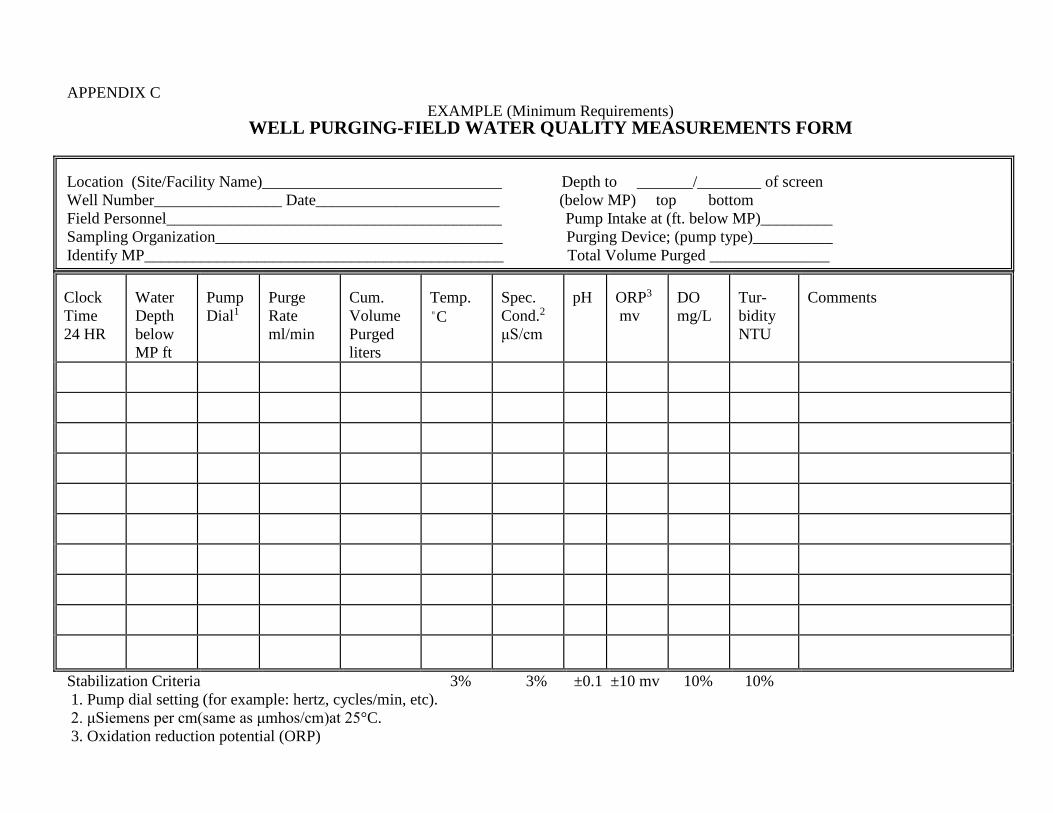
APPENDIX C EXAMPLE (Minimum Requirements)
WELL PURGING-FIELD WATER QUALITY MEASUREMENTS FORM Location (Site/Facility Name)______________________________ Depth to _______/________ of screen Well Number________________ Date_______________________ (below MP) top bottom Field Personnel__________________________________________ Pump Intake at (ft. below MP)_________ Sampling Organization____________________________________ Purging Device; (pump type)__________ Identify MP_____________________________________________ Total Volume Purged _______________ Clock Time 24 HR
Water Depth below MP ft
PumpDial1
Purge Rate ml/min
Cum. Volume Purged liters
Temp. "C
Spec. Cond.2 μS/cm
pH
ORP3 mv
DO mg/L
Tur-bidity NTU
Comments
Stabilization Criteria 3% 3% ±0.1 ±10 mv 10% 10% 1. Pump dial setting (for example: hertz, cycles/min, etc). 2. μSiemens per cm(same as μmhos/cm)at 25°C. 3. Oxidation reduction potential (ORP)