Embed Size (px)
Citation preview
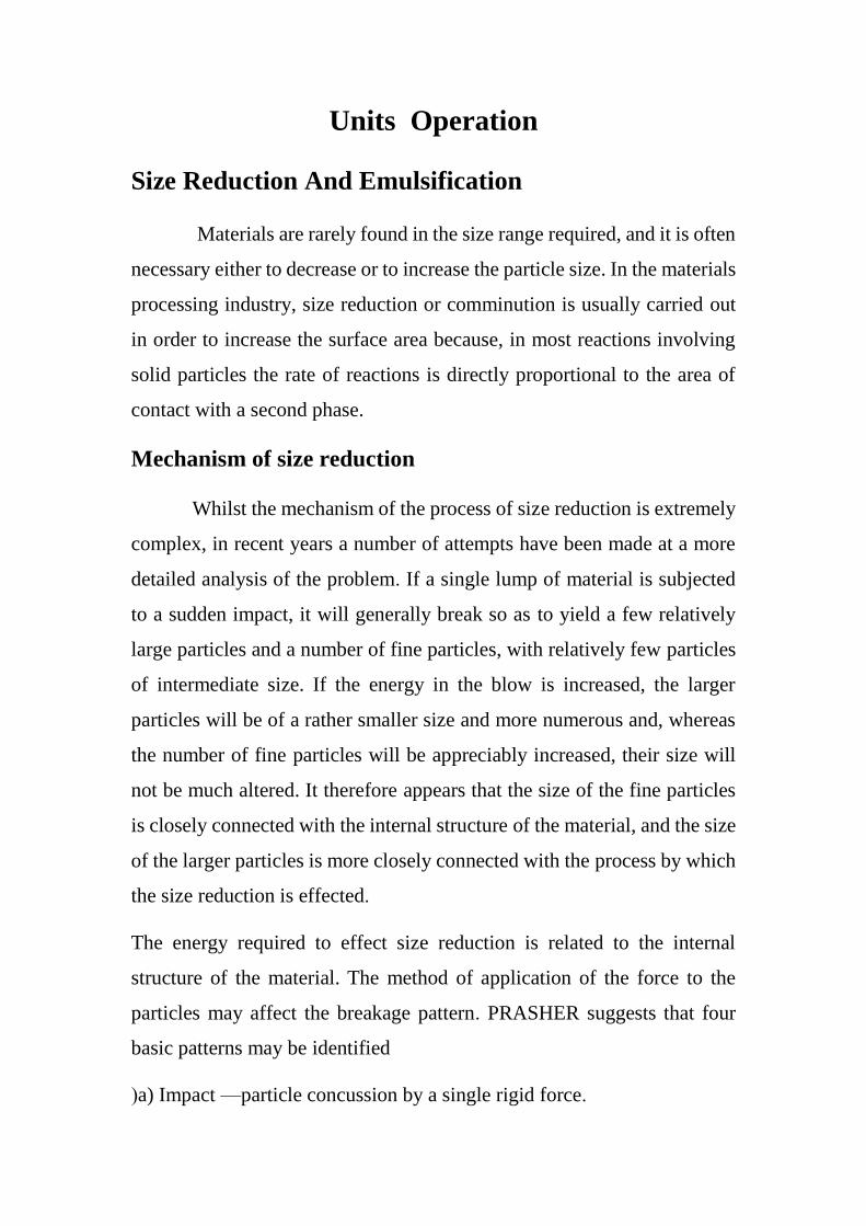
Units Operation
Size Reduction And Emulsification
Materials are rarely found in the size range required, and it is often
necessary either to decrease or to increase the particle size. In the materials
processing industry, size reduction or comminution is usually carried out
in order to increase the surface area because, in most reactions involving
solid particles the rate of reactions is directly proportional to the area of
contact with a second phase.
Mechanism of size reduction
Whilst the mechanism of the process of size reduction is extremely
complex, in recent years a number of attempts have been made at a more
detailed analysis of the problem. If a single lump of material is subjected
to a sudden impact, it will generally break so as to yield a few relatively
large particles and a number of fine particles, with relatively few particles
of intermediate size. If the energy in the blow is increased, the larger
particles will be of a rather smaller size and more numerous and, whereas
the number of fine particles will be appreciably increased, their size will
not be much altered. It therefore appears that the size of the fine particles
is closely connected with the internal structure of the material, and the size
of the larger particles is more closely connected with the process by which
the size reduction is effected.
The energy required to effect size reduction is related to the internal
structure of the material. The method of application of the force to the
particles may affect the breakage pattern. PRASHER suggests that four
basic patterns may be identified
(a) Impact —particle concussion by a single rigid force.
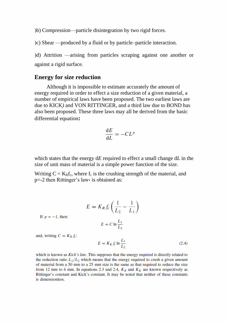
(b) Compression—particle disintegration by two rigid forces.
(c) Shear —produced by a fluid or by particle–particle interaction.
(d) Attrition —arising from particles scraping against one another or
against a rigid surface.
Energy for size reduction
Although it is impossible to estimate accurately the amount of
energy required in order to effect a size reduction of a given material, a
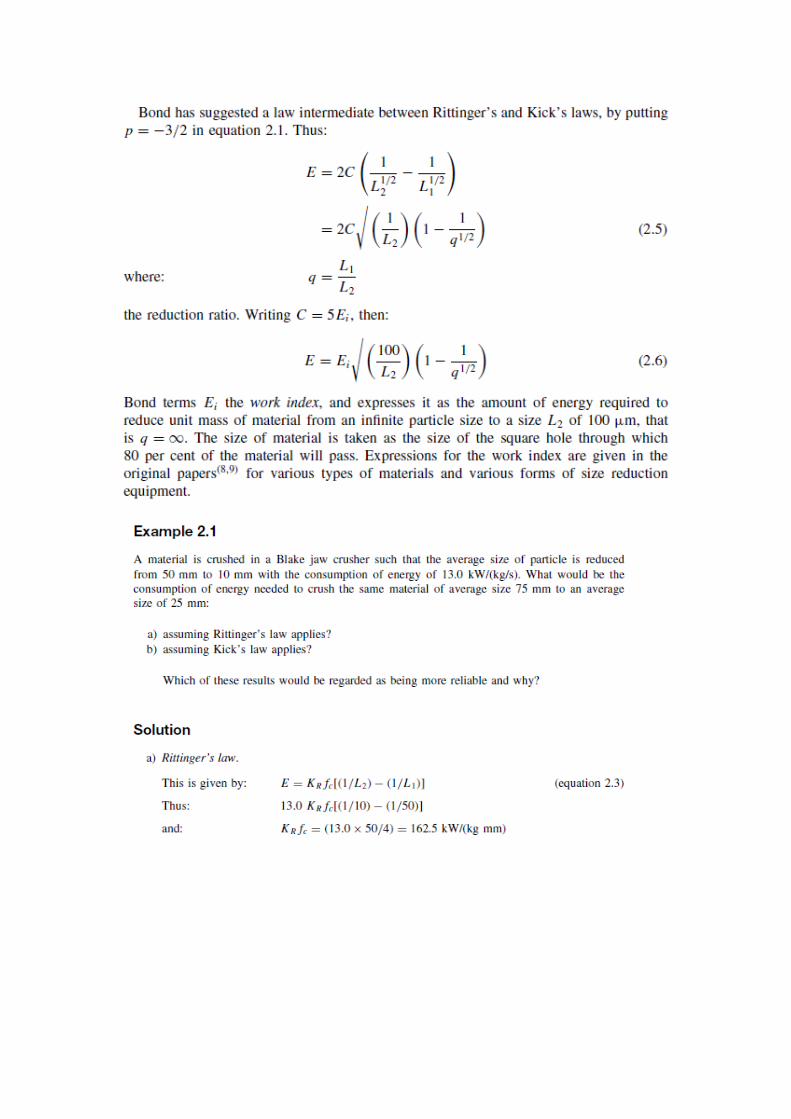
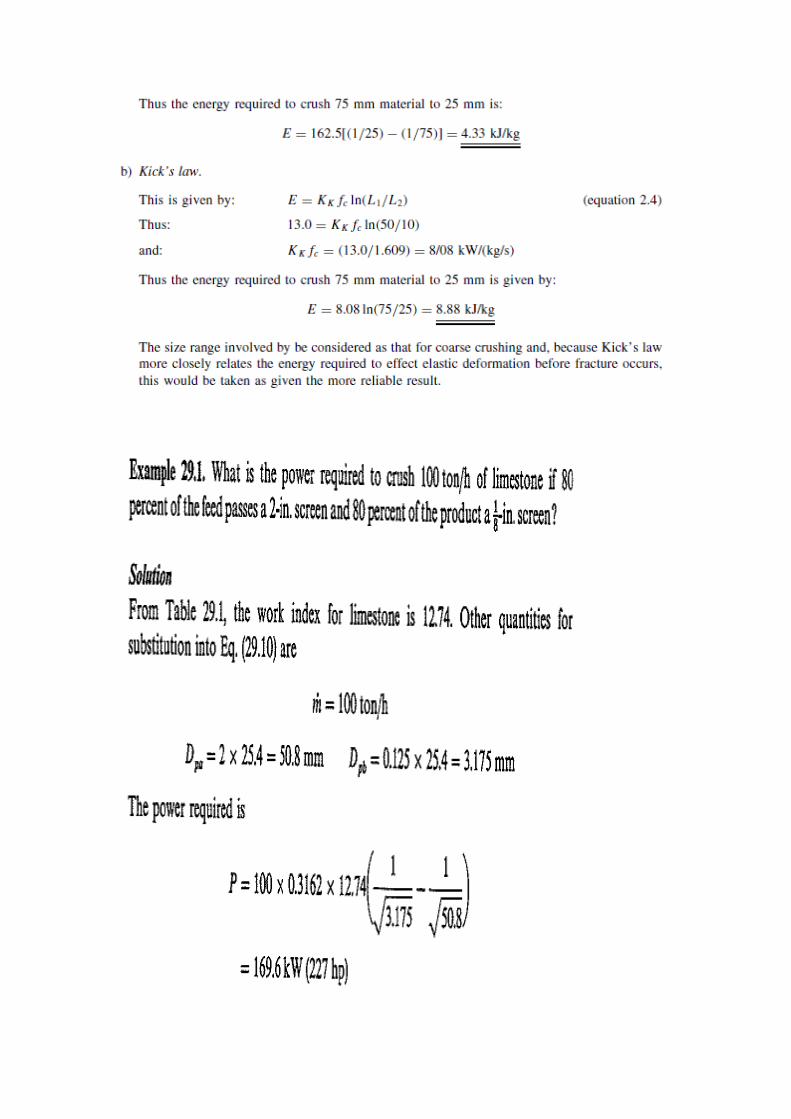
number of empirical laws have been proposed. The two earliest laws are
due to KICK) and VON RITTINGER, and a third law due to BOND has
also been proposed. These three laws may all be derived from the basic
differential equation:
which states that the energy dE required to effect a small change dL in the
size of unit mass of material is a simple power function of the size.
Writing C = KRfc, where fc is the crushing strength of the material, and
p=-2 then Rittinger’s law, is obtained as:
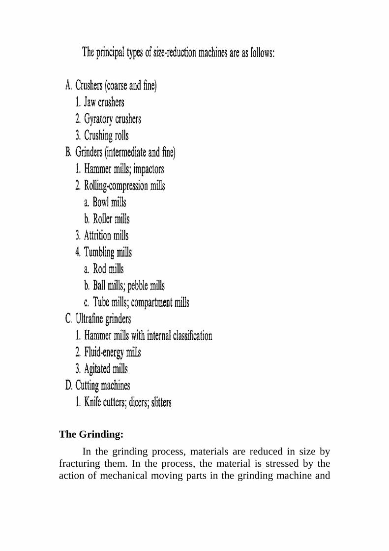
The Grinding:
In the grinding process, materials are reduced in size by
fracturing them. In the process, the material is stressed by the
action of mechanical moving parts in the grinding machine and
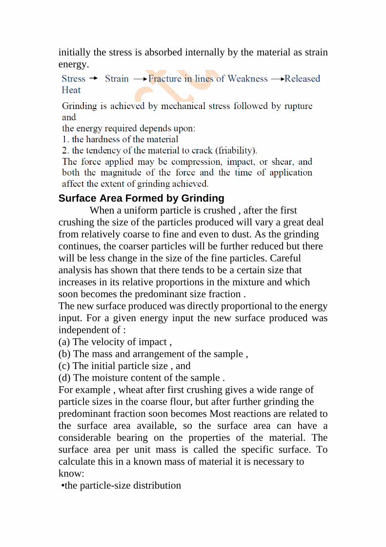
initially the stress is absorbed internally by the material as strain
energy.
Surface Area Formed by Grinding When a uniform particle is crushed , after the first
crushing the size of the particles produced will vary a great deal
from relatively coarse to fine and even to dust. As the grinding
continues, the coarser particles will be further reduced but there
will be less change in the size of the fine particles. Careful
analysis has shown that there tends to be a certain size that
increases in its relative proportions in the mixture and which
soon becomes the predominant size fraction .
The new surface produced was directly proportional to the energy
input. For a given energy input the new surface produced was
independent of :
(a) The velocity of impact ,
(b) The mass and arrangement of the sample ,
(c) The initial particle size , and
(d) The moisture content of the sample .
For example , wheat after first crushing gives a wide range of
particle sizes in the coarse flour, but after further grinding the
predominant fraction soon becomes Most reactions are related to
the surface area available, so the surface area can have a
considerable bearing on the properties of the material. The
surface area per unit mass is called the specific surface. To
calculate this in a known mass of material it is necessary to
know :
•the particle-size distribution

•the shape factor of the particles.
The particle size gives one dimension that can be called the
Typical Dimension, Dp of a particle. This has now to be related
to the surface area. We can write, arbitrarily:
Where
Vp is the volume of the particle.
Ap is the area of the particle surface
Dp is the typical dimension of the particle
q is factor of the particle geometries.
And , The ratio of surface area to volume is:
Example :
In an analysis of ground salt using Tyler sieves, it was found
that 38% of the total salt passed through a 7-mesh sieve and was
caught on a 9-mesh sieve. For one of the finer fractions, 5%
passed an 80-mesh sieve but was retained on a 115-mesh sieve.
Estimate the surface areas of these two fractions in a 5 kg sample
of the salt, if the density of salt is 1050 kg/m3 and the shape factor
is 1.75.
Aperture of Tyler sieves ,
7 mesh = 2.83 mm
9 mesh = 2.00 mm
80 mesh = 0.177 mm
115 mesh = 0.125 mm .
Solution :
Mean aperture 7 and 9 mesh = 2.41 mm = 2.4 x 10⁻³m
Mean aperture 80 and 115 mesh = 0.151 mm = 0.151 x 10⁻³m
At = (6 x 1.75 x0.38 x 5)/(1050x 2.41x10-3)
At = 7.88 m2
At = (6 x 1.75x 0.05 x 5)/( 1050 x 0.151x10-3)
At = 16.6 m2.
Emulsification
Emulsions are stable suspensions of one liquid in another,
the liquids being immiscible. Stability of the emulsion is obtained
by dispersion of very fine droplets of one liquid, called
the disperse phase, through the other liquid, which is called
the continuous phase. The emulsion is stable when it can persist
without change, for long periods of time, without the droplets of
the disperse phase coalescing with each other, or rising or settling.
The stability of an emulsion is controlled by
interfacial surface forces,
size of the disperse phase droplets,
viscous properties of the continuous phase and
density difference between the two phases.
The dispersed particles in the emulsion have a very large surface
area, which is created in the process of emulsification. Surface
effects depend upon the properties of the materials of the two
phases, but very often a third component is added which is
absorbed at the interface and which helps to prevent the droplets
from coalescing. These added materials are called emulsifying
agents and examples are phosphates and glycerol monostearate.
Stokes' Law gives a qualitative indication of the physical factors
that influence the stability of an emulsion. This is because the
relative flow of the particles under gravitational forces may break
the emulsion, so stability is enhanced by small settling velocities.
From eqn.
v = D2g(ρc – ρd)/18µc
where:
v: settling velocity
D:drops diameter
g : specific gravity
ρc , ρd :densities for continuous and dispersed face
µc: viscosity of continuous face.
Motion of Particles in a Fluid
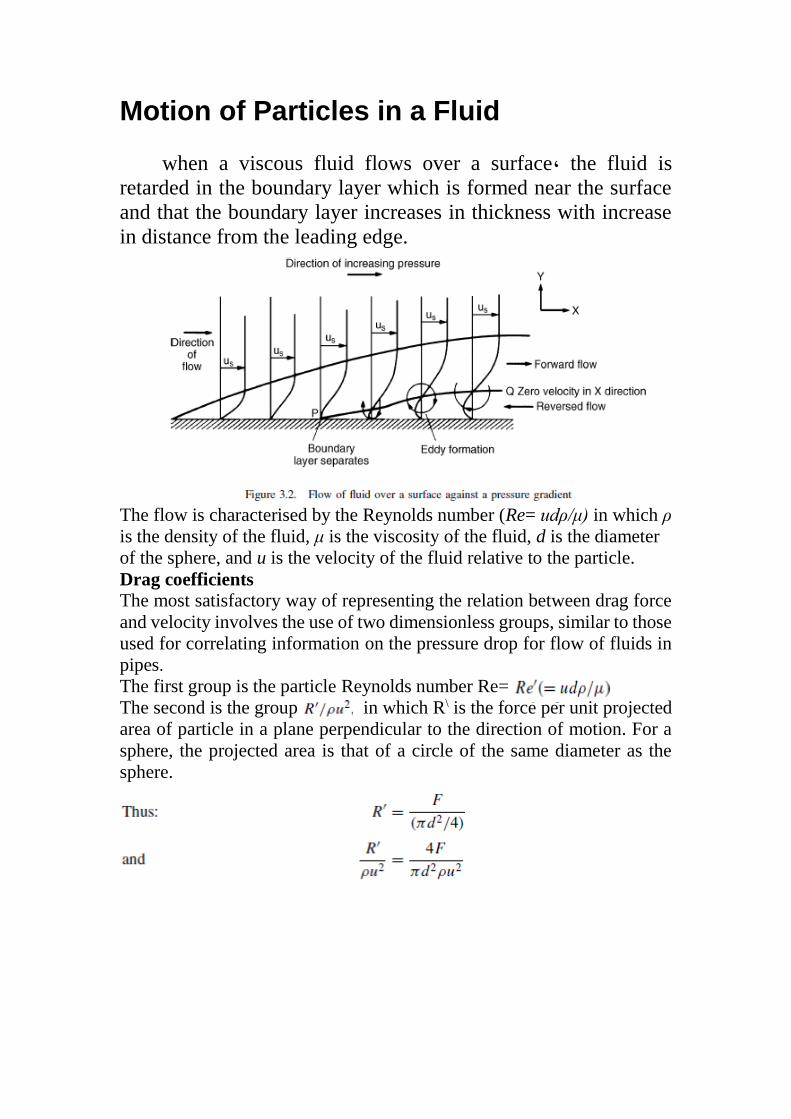
when a viscous fluid flows over a surface, the fluid is
retarded in the boundary layer which is formed near the surface
and that the boundary layer increases in thickness with increase
in distance from the leading edge.
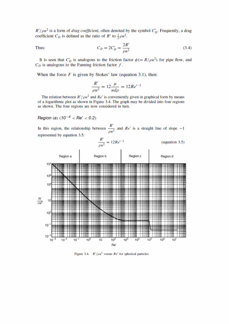
The flow is characterised by the Reynolds number (Re= udρ/μ) in which ρ
is the density of the fluid, μ is the viscosity of the fluid, d is the diameter
of the sphere, and u is the velocity of the fluid relative to the particle. Drag coefficients
The most satisfactory way of representing the relation between drag force
and velocity involves the use of two dimensionless groups, similar to those
used for correlating information on the pressure drop for flow of fluids in
pipes.
The first group is the particle Reynolds number Re=
The second is the group in which R\ is the force per unit projected
area of particle in a plane perpendicular to the direction of motion. For a
sphere, the projected area is that of a circle of the same diameter as the
sphere.
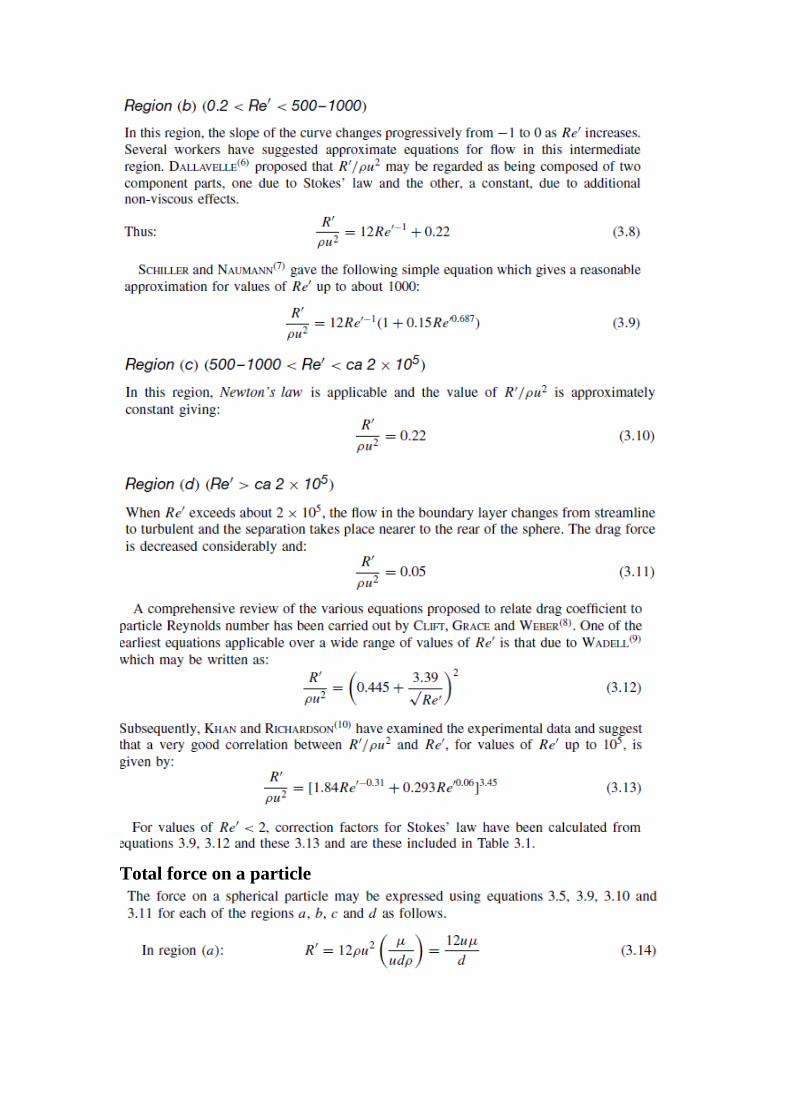
Total force on a particle
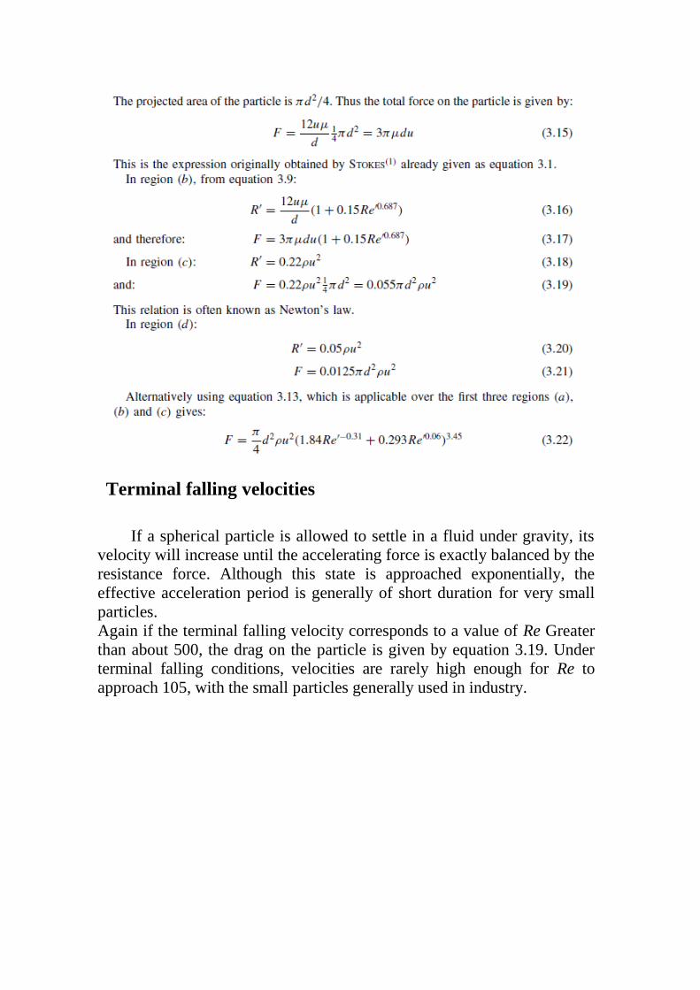
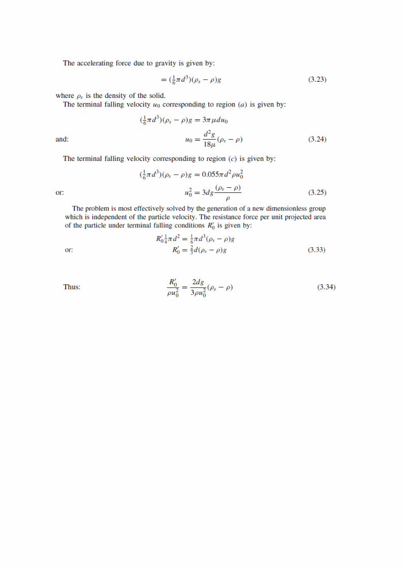
Terminal falling velocities
If a spherical particle is allowed to settle in a fluid under gravity, its
velocity will increase until the accelerating force is exactly balanced by the
resistance force. Although this state is approached exponentially, the
effective acceleration period is generally of short duration for very small
particles.
Again if the terminal falling velocity corresponds to a value of Re Greater
than about 500, the drag on the particle is given by equation 3.19. Under
terminal falling conditions, velocities are rarely high enough for Re to
approach 105, with the small particles generally used in industry.


MOTION OF PARTICLES IN A CENTRIFUGAL FIELD

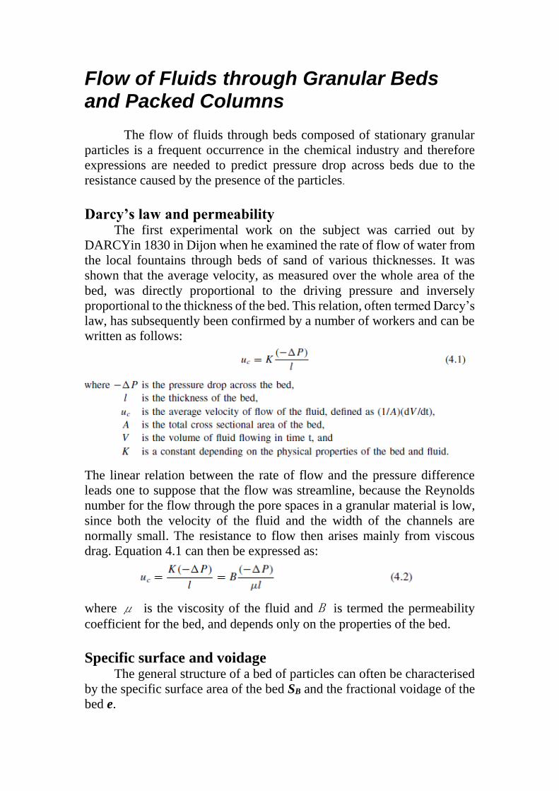
Flow of Fluids through Granular Beds and Packed Columns
The flow of fluids through beds composed of stationary granular
particles is a frequent occurrence in the chemical industry and therefore
expressions are needed to predict pressure drop across beds due to the
resistance caused by the presence of the particles.
Darcy’s law and permeability The first experimental work on the subject was carried out by
DARCYin 1830 in Dijon when he examined the rate of flow of water from
the local fountains through beds of sand of various thicknesses. It was
shown that the average velocity, as measured over the whole area of the
bed, was directly proportional to the driving pressure and inversely
proportional to the thickness of the bed. This relation, often termed Darcy’s
law, has subsequently been confirmed by a number of workers and can be
written as follows:
The linear relation between the rate of flow and the pressure difference
leads one to suppose that the flow was streamline, because the Reynolds
number for the flow through the pore spaces in a granular material is low,
since both the velocity of the fluid and the width of the channels are
normally small. The resistance to flow then arises mainly from viscous
drag. Equation 4.1 can then be expressed as:
where μ is the viscosity of the fluid and B is termed the permeability
coefficient for the bed, and depends only on the properties of the bed.
Specific surface and voidage The general structure of a bed of particles can often be characterised
by the specific surface area of the bed SB and the fractional voidage of the
bed e.

SB is the surface area presented to the fluid per unit volume of bed when
the particles are packed in a bed. Its units are (length)−1.
e is the fraction of the volume of the bed not occupied by solid material
and is termed the fractional voidage, or porosity. It is dimensionless.
Thus the fractional volume of the bed occupied by solid material is (1 − e).
S is the specific surface area of the particles and is the surface area of a
particle divided by its volume. Its units are again (length)−1. For a sphere,
for example:
Streamline flow—Carman–Kozeny equation
Streamline and turbulent flow
Dependence of K__ on bed structure
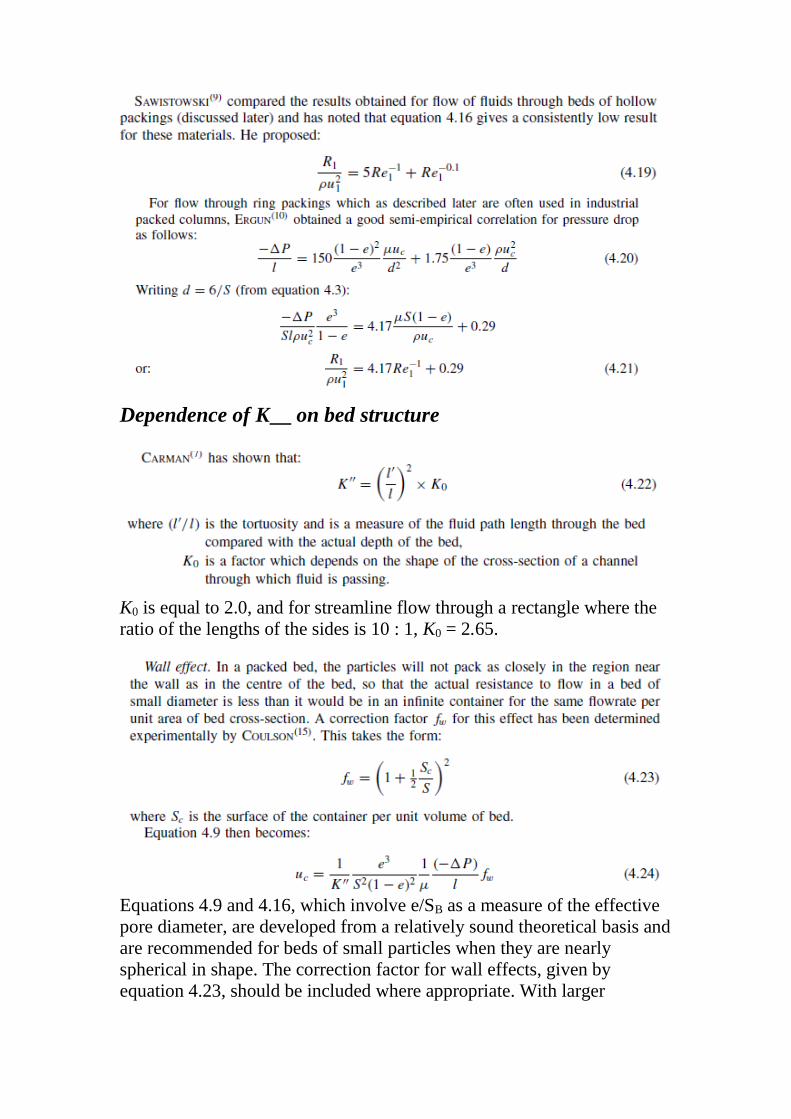
K0 is equal to 2.0, and for streamline flow through a rectangle where the
ratio of the lengths of the sides is 10 : 1, K0 = 2.65.
Equations 4.9 and 4.16, which involve e/SB as a measure of the effective
pore diameter, are developed from a relatively sound theoretical basis and
are recommended for beds of small particles when they are nearly
spherical in shape. The correction factor for wall effects, given by
equation 4.23, should be included where appropriate. With larger
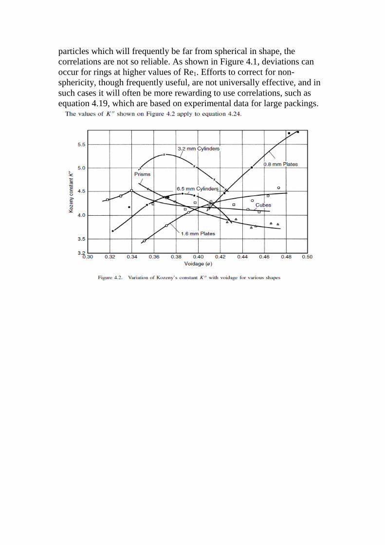
particles which will frequently be far from spherical in shape, the
correlations are not so reliable. As shown in Figure 4.1, deviations can
occur for rings at higher values of Re1. Efforts to correct for non-
sphericity, though frequently useful, are not universally effective, and in
such cases it will often be more rewarding to use correlations, such as
equation 4.19, which are based on experimental data for large packings.
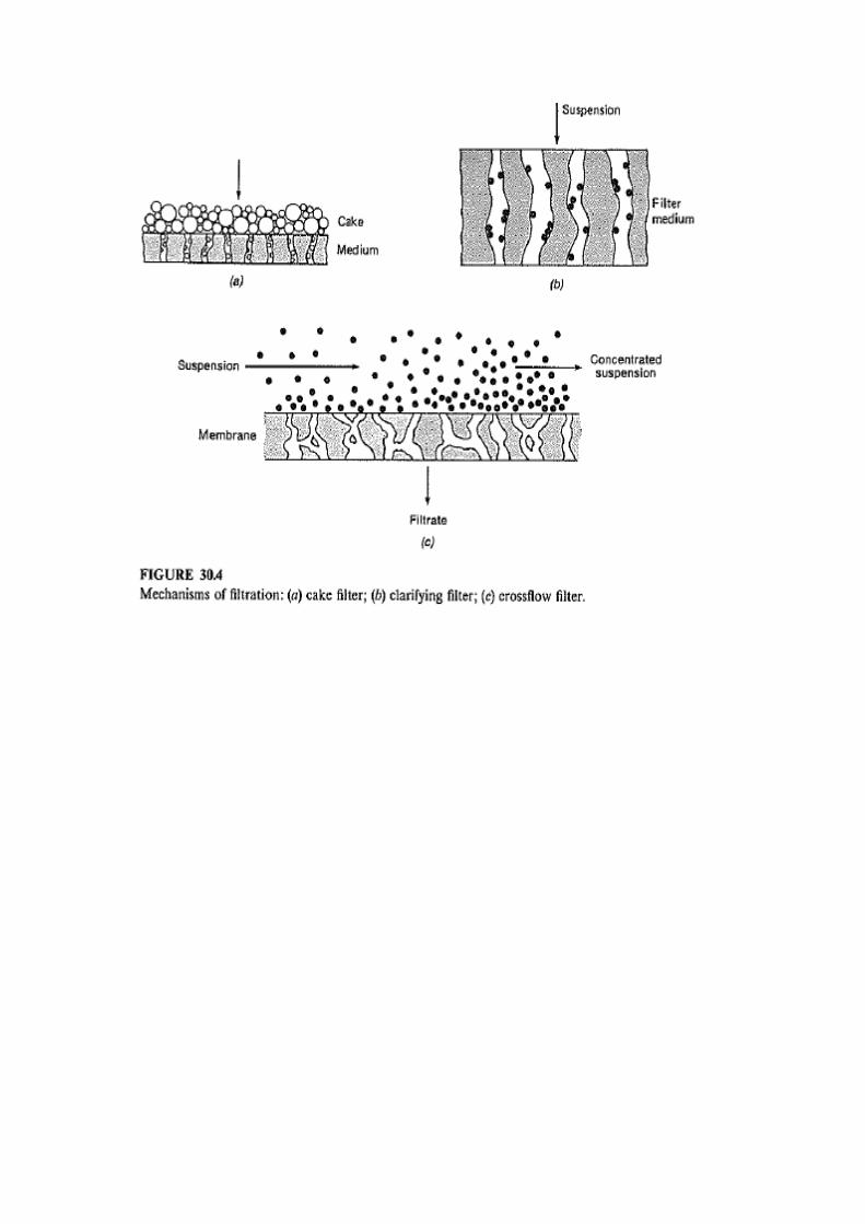
Filtration
- Removal of solids from fluid (gas or liquid) by a filtering medium on which solid particles are deposited.
- For filtration, external force is applied to a (gas or liquid + solid)
mixture to make it flow through the medium. - Filtration, when applied to gas cleaning, usually refers to the removal of fine particles like dust from air or flue gas. In such case, a polymeric fiber or cloth is wrapped over a pretreated metallic cylinder, capable of capturing micron size particles, including soot and fly-ash.
- Very large size ceramic based filters for high temperatur applications are also commercially
available.
- The liquid–solid filtration is often called “cake–filtration”,
because the separation of solids from the slurry by the filtering
medium is effective during the initial stages of filtration. Later, the
‘cakes' or deposits collected over the medium act as the filter.
Therefore, cake thickness increases during filtration and the
resistance (hydraulic) offered by the cake–material is larger than
that by the filtering medium.
There are two types of operation:
a. Constant-pressure
b. Constant filtering rate
In the 1st case, filtering rate varies with time, whereas in the 2nd
case, pressure–drop increases with time.
For ideal cake filtration, cake should be stable and large porosity.
There are two common types of filters:
a. The plate and frame press
b. Rotary-drum filter

Thus, the main factors to be considered when
selecting equipment and operating conditions are:
(a) The properties of the fluid, particularly its viscosity, density and
corrosive properties.
(b) The nature of the solid—its particle size and shape, size
distribution, and packing characteristics.
(c) The concentration of solids in suspension.
(d) The quantity of material to be handled, and its value.
(e) Whether the valuable product is the solid, the fluid, or both.
(f) Whether it is necessary to wash the filtered solids.
(g) Whether very slight contamination caused by contact of the
suspension or filtrate with the various components of the equipment
is detrimental to the product.
(h) Whether the feed liquor may be heated.
(i) Whether any form of pretreatment might be helpful.
The most important factors on which the rate of filtration depends
will be:
(a) The drop in pressure from the feed to the far side of the filter
medium.
(b) The area of the filtering surface.
(c) The viscosity of the filtrate.
(d) The resistance of the filter cake.
(e) The resistance of the filter medium and initial layers of cake.
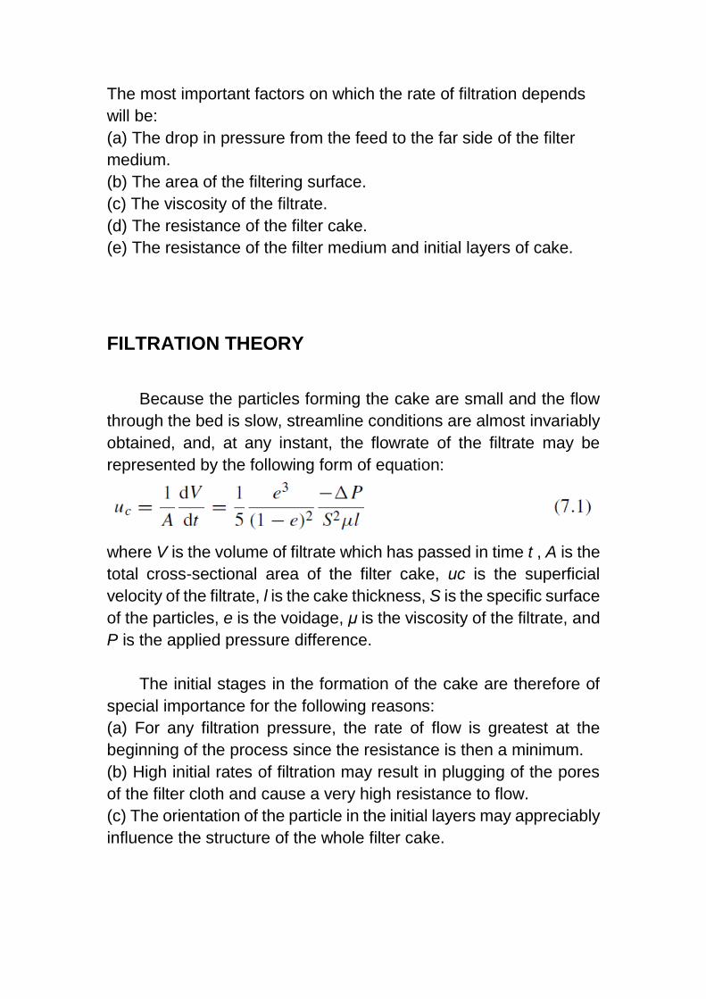
FILTRATION THEORY
Because the particles forming the cake are small and the flow
through the bed is slow, streamline conditions are almost invariably
obtained, and, at any instant, the flowrate of the filtrate may be
represented by the following form of equation:
where V is the volume of filtrate which has passed in time t , A is the
total cross-sectional area of the filter cake, uc is the superficial
velocity of the filtrate, l is the cake thickness, S is the specific surface
of the particles, e is the voidage, μ is the viscosity of the filtrate, and
P is the applied pressure difference.
The initial stages in the formation of the cake are therefore of
special importance for the following reasons:
(a) For any filtration pressure, the rate of flow is greatest at the
beginning of the process since the resistance is then a minimum.
(b) High initial rates of filtration may result in plugging of the pores
of the filter cloth and cause a very high resistance to flow.
(c) The orientation of the particle in the initial layers may appreciably
influence the structure of the whole filter cake.
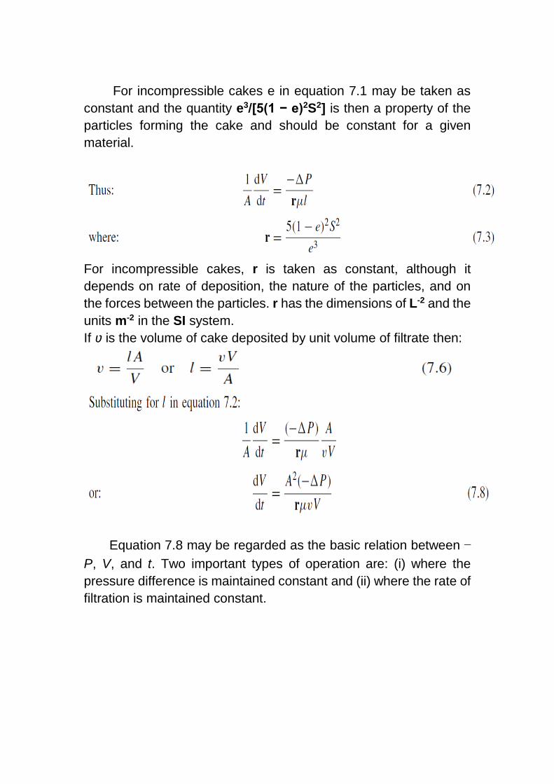
For incompressible cakes e in equation 7.1 may be taken as
constant and the quantity e3/[5(1 − e)2S2] is then a property of the
particles forming the cake and should be constant for a given
material.
For incompressible cakes, r is taken as constant, although it
depends on rate of deposition, the nature of the particles, and on
the forces between the particles. r has the dimensions of L-2 and the
units m-2 in the SI system.
If ʋ is the volume of cake deposited by unit volume of filtrate then:
Equation 7.8 may be regarded as the basic relation between −
P, V, and t. Two important types of operation are: (i) where the
pressure difference is maintained constant and (ii) where the rate of
filtration is maintained constant.
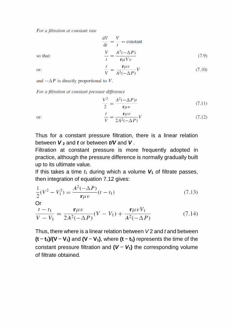
Thus for a constant pressure filtration, there is a linear relation
between V 2 and t or between t/V and V .
Filtration at constant pressure is more frequently adopted in
practice, although the pressure difference is normally gradually built
up to its ultimate value.
If this takes a time t1 during which a volume V1 of filtrate passes,
then integration of equation 7.12 gives:
Or
Thus, there where is a linear relation between V 2 and t and between
(t − t1)/(V − V1) and (V − V1), where (t − t1) represents the time of the
constant pressure filtration and (V − V1) the corresponding volume
of filtrate obtained.
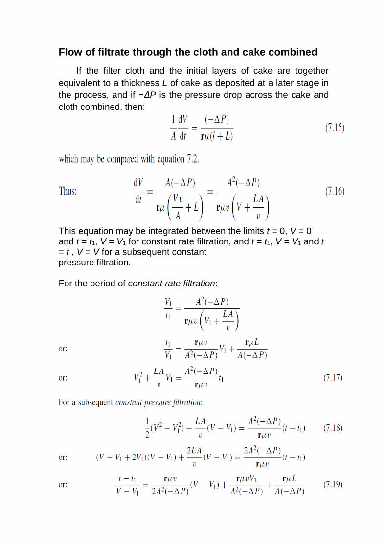
Flow of filtrate through the cloth and cake combined
If the filter cloth and the initial layers of cake are together
equivalent to a thickness L of cake as deposited at a later stage in
the process, and if −ΔP is the pressure drop across the cake and
cloth combined, then:
This equation may be integrated between the limits t = 0, V = 0 and t = t1, V = V1 for constant rate filtration, and t = t1, V = V1 and t = t , V = V for a subsequent constant pressure filtration. For the period of constant rate filtration:
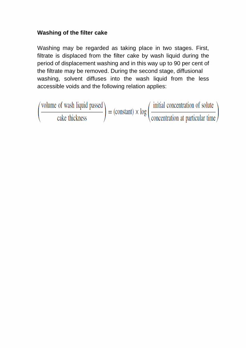
Washing of the filter cake
Washing may be regarded as taking place in two stages. First,
filtrate is displaced from the filter cake by wash liquid during the
period of displacement washing and in this way up to 90 per cent of
the filtrate may be removed. During the second stage, diffusional
washing, solvent diffuses into the wash liquid from the less
accessible voids and the following relation applies: