Embed Size (px)
Citation preview
1
Universal communications device Metcom T M..
Manual Order-No. E 856-102
1 NET (RUN)-LED for power on and logoff / logon 2 RI-LED: Ring Indication 3 DCD-LED: Data Carrier Detect 4 RxD-LED: Receive Data
5 TxD-LED: Transmit Data 6 Technical Data 7 Sealed device cover screw 8 Sealed terminal cover screw
Figure 1: Display and control panel Metcom T M..
1 General
The world-wide GSM radio networks (GSM := Global System for Mobile communication) provide besides digital voice communication the possibility to transmit data. In that operation mode is it possible to send fax, data and short messages (SMS). The universal communications device Metcom T M.. is supposed for remote inquiry of measurement data of any kind, especially however for telecounting applications.
2 Requirements
The universal communications device Landis & Gyr Metcon T M.. can be used in any GSM 900/1800 MHz network with an arbitrary number of providers. It requires however the infrastructure for operating mobile stations with 2 Watt (EGS900) or 1 Watt (GSM1800) transmission power. The device supports an interface for 3V SIM cards. For communication a SIM card with call number for 9600 Baud transmission is needed. For the Metcom T M.. communication modules produced by internationally renowned companies are used. These companies update their software packages regularly and add or change features. The software releases are continuously checked by the development department, but no responsibility for this software releases can be take over except of warranty granted by the module producer.
1 2 3 4 5 6
7
8
2
3 Safety precautions for the user
Aircraft safety
Cellular engines can interfere with an aircraft’s navigation system and its cellular network. The use of Metcom T M.. on board aircraft is forbidden by law. Failure to comply with this prohibition may lead to temporary suspension or permanent cancellation of cellular engine services for the person who infringes this prohibition and/or to legal action against said person.
Environments with explosive substances
a) Users are advised not to use the device in automotive service stations. b) Users are reminded of the necessity to comply with restrictions regarding the use of radio devices in fuel depots, chemicals plants and locations where explosives are ignited.
Non-ionising radiation
As is the case with other mobile radio transmitters, operating personnel are advised to use the device in the normal operating position only in order to ensure optimum performance and safety. Avoid touching the antenna.
Personnel
Installation and repairing should be done by experienced personnel only.
Connecting to other devices
In order to connect the Metcom T M.. to another device please read the device’s operation manual to obtain detailed information about safety. Don’t connect devices, which are not approved by manufacturer.
Precautions in the event of loss/theft of the Cellular Engine and the SIM card
If your Metcom T M.., your SIM card or both go missing, notify your network operator immediately in order to avoid misuse.
4 Montages and connections (see chapter 12 Terminal Assignment)
The device is equipped with a built-in, low-loss switched power supply, which enables it to operate on a wide-range AC or DC supply voltage:
AC: 85 V - 240 V or DC: 60 V - 375 V The installation must be done in a way, that even in the case of cable break no dangerous voltages are applied to touchable parts of the device including the antenna. This can be accomplished e.g. by using cable ties and appropriate shortening of the cables.
Attention:
Wrong connection made with Metcom T M.. may destroy the device.
Therefore attention has to be taken, that
only the clamps shown in the terminal assignment diagram are connected.
devices with the same type designation may have different designations for the clamps. Please connect the device as shown in the delivered circuit diagram (in terminal cover).
the device must be supplied with the voltage given on the nameplate only.
Open the device in voltage free state only!
Capacitors inside may be loaded to dangerous voltage even after the device is disconnected from mains. Be careful when touching parts inside!
The RTS/CTS jumper can be set if a bus interface (e.g. 20mA, M-Bus, RS485) or a three wired RS232 (GND, TxD, RxD) is used.
3
5 Installation hints
Delivered devices are either programmed according to order or with standard parameters if nothing was specified. Before installation the Metcom can be configured for the given application using a PC and a parametering adapter (see chapter 10 Programming the device).
6 Inserting the SIM card
Security-hints:
Store SIM cards always out of reach of small children!
The SIM card and its contact pads can be easily damaged by scratching or bending. Please be careful when inserting or removing it.
Always switch off the device when inserting or removing the SIM card.
Capacitors inside may be loaded to dangerous voltage even after the device is disconnected from mains. Be careful when touching parts inside !
For installation insert the SIM card correctly and tighten it by using the clamp of the card reader:
1. Remove the covers from device and terminals.
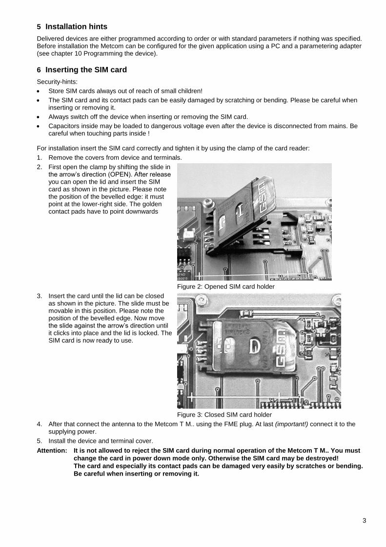
2. First open the clamp by shifting the slide in the arrow’s direction (OPEN). After release you can open the lid and insert the SIM card as shown in the picture. Please note the position of the bevelled edge: it must point at the lower-right side. The golden contact pads have to point downwards
Figure 2: Opened SIM card holder
3. Insert the card until the lid can be closed as shown in the picture. The slide must be movable in this position. Please note the position of the bevelled edge. Now move the slide against the arrow’s direction until it clicks into place and the lid is locked. The SIM card is now ready to use.
Figure 3: Closed SIM card holder
4. After that connect the antenna to the Metcom T M.. using the FME plug. At last (important!) connect it to the supplying power.
5. Install the device and terminal cover.
Attention: It is not allowed to reject the SIM card during normal operation of the Metcom T M.. You must
change the card in power down mode only. Otherwise the SIM card may be destroyed!
The card and especially its contact pads can be damaged very easily by scratches or bending.
Be careful when inserting or removing it.
4
7 Display and control panel (Figure 1) – differently according to appliance-implementation
Pos. Function
1 NET-LED for power on and logoff / logon blinks by logoff
2 RI-LED: Ring Indication lights, when the modem rings
3 DCD-LED: Data Carrier Detect lights, when the modem has built a data link to remote station
4 RxD-LED: Receive Data lights, when data is transferred from modem to target device
5 TxD-LED: Transmit Data lights, when data is transferred from target device to modem
6 Technical Data
7 Sealed device cover screw
8 Sealed terminal cover screw
8 Function
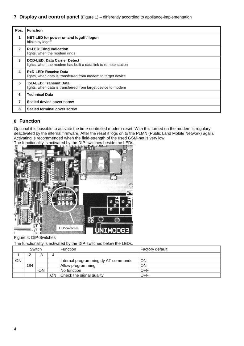
Optional it is possible to activate the time-controlled modem-reset. With this turned on the modem is regulary deactivated by the internal firmware. After the reset it logs on to the PLMN (Public Land Mobile Network) again. Activating is recommended when the field-strength of the used GSM-net is very low. The functionality is activated by the DIP-switches beside the LEDs.
DIP-Switches
Figure 4: DIP-Switches
The functionality is activated by the DIP-switches below the LEDs.
Switch Function Factory default
1 2 3 4
ON Internal programming dy AT commands ON
ON Allow programming ON
ON No function OFF
ON Check the signal quality OFF
5
Function:
Switch 1 = ON: The internal CPU can optionally send the AT commands to the TC350 module. This is useful when using a SIM card, which demands the PIN to be entered after powerfail. The AT commands are sent about 10 seconds after power-on and immediately after every modem reset.
Switch 2 = ON: Allow programming (for example: PIN, baud rate, data format, cyclic reset...).
Switch 3 = ON: No function
Switch 4 = ON: Check the signal quality and show it by INF-LED (right, near the TxD-LED): INF-LED on: good signal quality INF-LED blinks: medium signal quality INF-LED off: bad signal quality After the test set the switch 4 to off!
9 Interface
The interface for connecting the target device can be specified by plugging the appropriate interface module. The following module types are available now:
RS232 (uses signals RxD, TxD, CTS, RTS, GND): terminal - standard
RS232 (uses signals RxD, TxD, CTS, RTS, GND, DTR, DCD, DSR): RJ45 - option
CS (20 mA current loop) active (supplies current, for max. 6 to 8 meters) or passive: terminal - option
RS485: terminal - option
M-Bus interface module, active (can supply 25 devices max.) or passive: terminal - option
Only one of multiple built-in interfaces (optional) can be active at the same time. The others serve in this case for level conversion.
Communication is possible with many standard protocols, like SCTM, LSV1, DLMS, IEC1107, IEC60870 (transparent reading) etc.
10 Programming the device
Before installing the modem it has to be programmed in order to meet the demands. The baud rate and data format for connecting to the target device and the transmission mode and transmission rates must be adjusted. On delivery the following default parameters are active (if not differently mentioned, see terminal cover):
ATS0=1 This parameter setting determines the number of rings (here 1) before automatic answering
AT&D0 This parameter determines how the modem responds when circuit DTR is changed from ON to OFF during data mode. With setting 0 the modem ignores DTR
ATE0 No local echo
ATQ0 V0 Result is presented as number
AT+IPR=0 Autobauding: don´t change this value!
AT+CBST=7,0,1 The modem selects the bearer service with data rate 9600 Baud (V.32), asynchronous, non-transparent mode to be used when data calls are originated
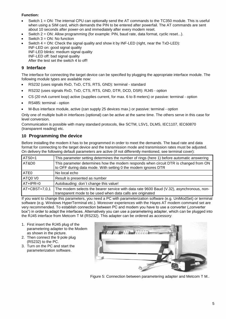
If you want to change this parameters, you need a PC with parameterization software (e.g. UniModSet) or terminal software (e.g. Windows HyperTerminal etc.). Moreover experiences with the Hayes AT modem command set are very recommended. To establish connection between PC and modem you have to use a converter („converter box“) in order to adapt the interfaces. Alternatively you can use a parametering adapter, which can be plugged into the RJ45 interface from Metcom T M (RS232). This adapter can be ordered as accessory: 1. First insert the RJ45 plug of the
parametering adapter to the Modem as shown in the picture.
2. Then connect the 9 pole plug (RS232) to the PC.
3. Turn on the PC and start the parameterization software.
Figure 5: Connection between parametering adapter and Metcom T M..
6
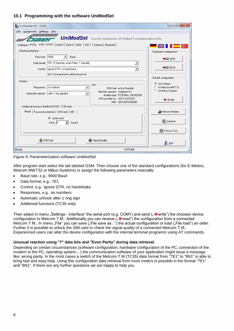
10.1 Programming with the software UniModSet
Figure 6: Parameterization software UniModSet After program start select the tab labeled GSM. Then choose one of the standard configurations (for E-Meters, Metcom MWT32 or MBus-Systems) or assign the following parameters manually:
Baud rate, e.g.: 9600 Baud
Data format, e.g.: 7E1
Control, e.g.: ignore DTR, no handshake
Responses, e.g.: as numbers
Automatic unhook after 1 ring sign
Additional functions (TC35 only)
Then select in menu „Settings - Interface“ the serial port (e.g. COM1) and send („write“) the choosen device configuration to Metcom T M.. Additionally you can receive („read“) the configuration from a connected Metcom T M.. In menu „File“ you can save („File save as...“) the actual configuration or load („File load“) an older. Further it is possible to unlock the SIM card or check the signal quality of a connected Metcom T M.. Experienced users can alter the device configuration with the internal terminal programm using AT commands.
Unusual reaction using "7" data bits and "Even Parity" during data retrieval.
Depending on certain circumstances (software configuration, hardware configuration of the PC, connection of the modem to the PC, operating system,...) the communication software of your application might issue a message like: wrong parity. In the most cases a switch of the Metcom T M (TC35) data format from "7E1" to "8N1" is able to bring fast and easy help. Using this configuration data retrieval from most meters is possible in the format "7E1" and "8N1". If there are any further questions we are happy to help you.
7
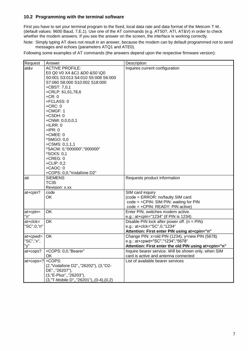
10.2 Programming with the terminal software First you have to set your terminal program to the fixed, local data rate and data format of the Metcom T M.. (default values: 9600 Baud, 7,E,1). Use one of the AT commands (e.g. ATS0?, ATI, AT&V) in order to check whether the modem answers. If you see the answer on the screen, the interface is working correctly.
Note: Simply typing AT does not result in an answer, because the modem can by default programmed not to send messages and echoes (parameters ATQ1 and ATE0).
Following some examples of AT commands (the answers depend upon the respective firmware version):
Request Answer Description
at&v
ACTIVE PROFILE: E0 Q0 V0 X4 &C1 &D0 &S0 \Q0 S0:001 S3:013 S4:010 S5:008 S6:000 S7:060 S8:000 S10:002 S18:000 +CBST: 7,0,1 +CRLP: 61,61,78,6 +CR: 0 +FCLASS: 0 +CRC: 0 +CMGF: 1 +CSDH: 0 +CNMI: 0,0,0,0,1 +ILRR: 0 +IPR: 0 +CMEE: 0 ^SMGO: 0,0 +CSMS: 0,1,1,1 ^SACM: 0,"000000","000000" ^SCKS: 0,1 +CREG: 0 +CLIP: 0,2 +CAOC: 0 +COPS: 0,0,"Vodafone D2"
Inquires current configuration
ati SIEMENS TC35 Revision: x.xx
Requests product information
at+cpin? code OK
SIM card inquiry (code = ERROR: no/faulty SIM card code = +CPIN: SIM PIN: waiting for PIN code = +CPIN: READY: PIN active)
at+cpin= "n"
OK Enter PIN, switches modem active. e.g.: at+cpin="1234" (if PIN is 1234)
at+clck= "SC",0,"n"
OK Disable PIN lock after power off. (n = PIN) e.g.: at+clck="SC",0,"1234"
Attention: First enter PIN using at+cpin="n"
at+cpwd= "SC","x", "y"
OK Change PIN: x=old PIN (1234), y=new PIN (5678) e.g.: at+cpwd="SC","1234",“5678“
Attention: First enter the old PIN using at+cpin="n"
at+cops? +COPS: 0,0,"Bearer" OK
Inquire bearer service. Will be shown only, when SIM card is active and antenna connected
at+cops=? +COPS: (2,"Vodafone D2",,"26202"), (3,"O2-DE",,"26207"), (3,"E-Plus",,"26203"), (3,"T-Mobile D",,"26201"),,(0-4),(0,2)
List of available bearer services
8
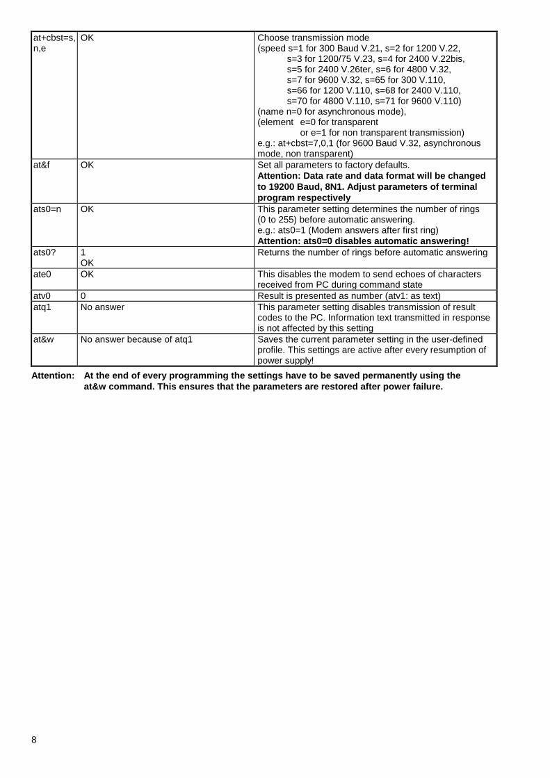
at+cbst=s, n,e
OK Choose transmission mode (speed s=1 for 300 Baud V.21, s=2 for 1200 V.22,
s=3 for 1200/75 V.23, s=4 for 2400 V.22bis, s=5 for 2400 V.26ter, s=6 for 4800 V.32, s=7 for 9600 V.32, s=65 for 300 V.110, s=66 for 1200 V.110, s=68 for 2400 V.110, s=70 for 4800 V.110, s=71 for 9600 V.110)
(name n=0 for asynchronous mode), (element e=0 for transparent
or e=1 for non transparent transmission) e.g.: at+cbst=7,0,1 (for 9600 Baud V.32, asynchronous mode, non transparent)
at&f OK Set all parameters to factory defaults.
Attention: Data rate and data format will be changed
to 19200 Baud, 8N1. Adjust parameters of terminal
program respectively
ats0=n OK This parameter setting determines the number of rings (0 to 255) before automatic answering. e.g.: ats0=1 (Modem answers after first ring)
Attention: ats0=0 disables automatic answering!
ats0? 1 OK
Returns the number of rings before automatic answering
ate0 OK This disables the modem to send echoes of characters received from PC during command state
atv0 0 Result is presented as number (atv1: as text)
atq1 No answer This parameter setting disables transmission of result codes to the PC. Information text transmitted in response is not affected by this setting
at&w No answer because of atq1 Saves the current parameter setting in the user-defined profile. This settings are active after every resumption of power supply!
Attention: At the end of every programming the settings have to be saved permanently using the
at&w command. This ensures that the parameters are restored after power failure.
9
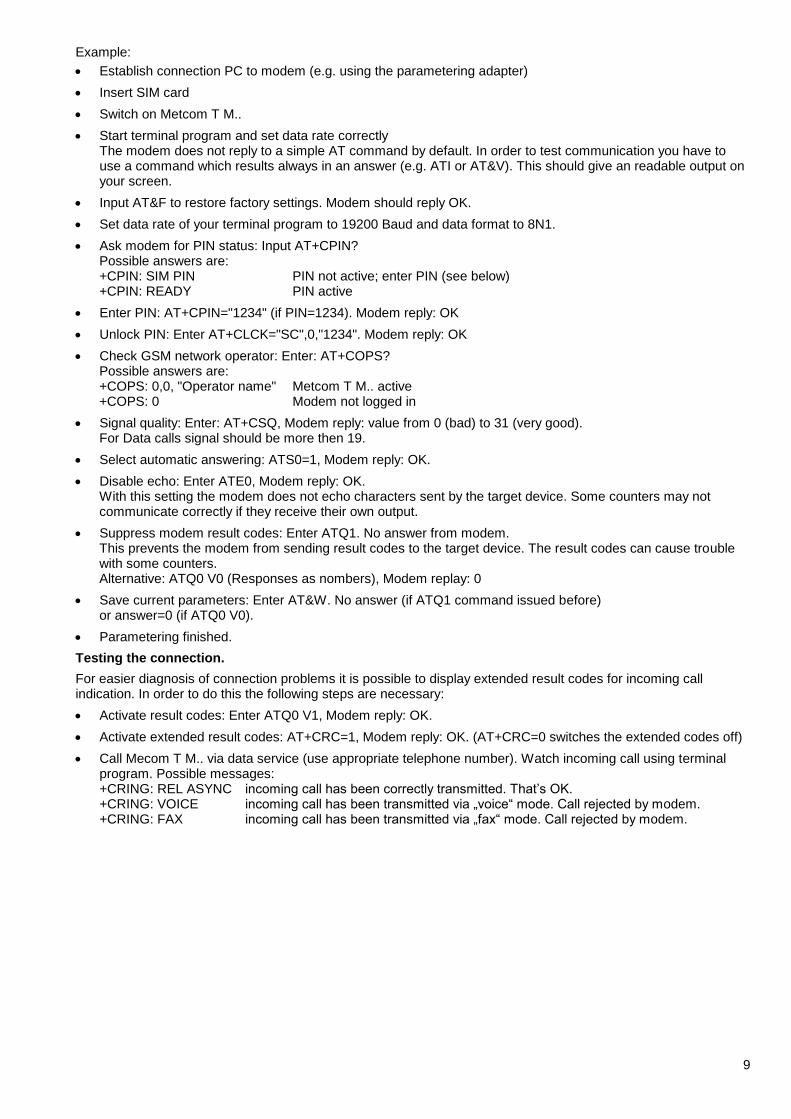
Example:
Establish connection PC to modem (e.g. using the parametering adapter)
Insert SIM card
Switch on Metcom T M..
Start terminal program and set data rate correctly The modem does not reply to a simple AT command by default. In order to test communication you have to use a command which results always in an answer (e.g. ATI or AT&V). This should give an readable output on your screen.
Input AT&F to restore factory settings. Modem should reply OK.
Set data rate of your terminal program to 19200 Baud and data format to 8N1.
Ask modem for PIN status: Input AT+CPIN? Possible answers are: +CPIN: SIM PIN PIN not active; enter PIN (see below) +CPIN: READY PIN active
Enter PIN: AT+CPIN="1234" (if PIN=1234). Modem reply: OK
Unlock PIN: Enter AT+CLCK="SC",0,"1234". Modem reply: OK
Check GSM network operator: Enter: AT+COPS? Possible answers are: +COPS: 0,0, "Operator name" Metcom T M.. active +COPS: 0 Modem not logged in
Signal quality: Enter: AT+CSQ, Modem reply: value from 0 (bad) to 31 (very good). For Data calls signal should be more then 19.
Select automatic answering: ATS0=1, Modem reply: OK.
Disable echo: Enter ATE0, Modem reply: OK. With this setting the modem does not echo characters sent by the target device. Some counters may not communicate correctly if they receive their own output.
Suppress modem result codes: Enter ATQ1. No answer from modem. This prevents the modem from sending result codes to the target device. The result codes can cause trouble with some counters. Alternative: ATQ0 V0 (Responses as nombers), Modem replay: 0
Save current parameters: Enter AT&W. No answer (if ATQ1 command issued before) or answer=0 (if ATQ0 V0).
Parametering finished.
Testing the connection.
For easier diagnosis of connection problems it is possible to display extended result codes for incoming call indication. In order to do this the following steps are necessary:
Activate result codes: Enter ATQ0 V1, Modem reply: OK.
Activate extended result codes: AT+CRC=1, Modem reply: OK. (AT+CRC=0 switches the extended codes off)
Call Mecom T M.. via data service (use appropriate telephone number). Watch incoming call using terminal program. Possible messages: +CRING: REL ASYNC incoming call has been correctly transmitted. That’s OK. +CRING: VOICE incoming call has been transmitted via „voice“ mode. Call rejected by modem. +CRING: FAX incoming call has been transmitted via „fax“ mode. Call rejected by modem.
10
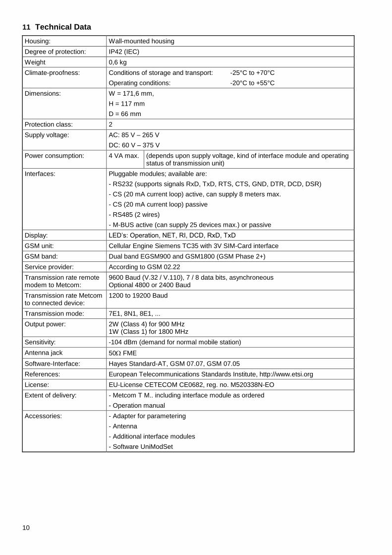
11 Technical Data
Housing: Wall-mounted housing
Degree of protection: IP42 (IEC)
Weight 0,6 kg
Climate-proofness: Conditions of storage and transport: -25°C to +70°C
Operating conditions: -20°C to +55°C
Dimensions: W = 171,6 mm,
H = 117 mm
D = 66 mm
Protection class: 2
Supply voltage: AC: 85 V – 265 V
DC: 60 V – 375 V
Power consumption: 4 VA max. (depends upon supply voltage, kind of interface module and operating status of transmission unit)
Interfaces: Pluggable modules; available are:
- RS232 (supports signals RxD, TxD, RTS, CTS, GND, DTR, DCD, DSR)
- CS (20 mA current loop) active, can supply 8 meters max.
- CS (20 mA current loop) passive
- RS485 (2 wires)
- M-BUS active (can supply 25 devices max.) or passive
Display: LED’s: Operation, NET, RI, DCD, RxD, TxD
GSM unit: Cellular Engine Siemens TC35 with 3V SIM-Card interface
GSM band: Dual band EGSM900 and GSM1800 (GSM Phase 2+)
Service provider: According to GSM 02.22
Transmission rate remote modem to Metcom:
9600 Baud (V.32 / V.110), 7 / 8 data bits, asynchroneous Optional 4800 or 2400 Baud
Transmission rate Metcom to connected device:
1200 to 19200 Baud
Transmission mode: 7E1, 8N1, 8E1, ...
Output power: 2W (Class 4) for 900 MHz 1W (Class 1) for 1800 MHz
Sensitivity: -104 dBm (demand for normal mobile station)
Antenna jack 50 FME
Software-Interface: Hayes Standard-AT, GSM 07.07, GSM 07.05
References: European Telecommunications Standards Institute, http://www.etsi.org
License: EU-License CETECOM CE0682, reg. no. M520338N-EO
Extent of delivery: - Metcom T M.. including interface module as ordered
- Operation manual
Accessories: - Adapter for parametering
- Antenna
- Additional interface modules
- Software UniModSet
11
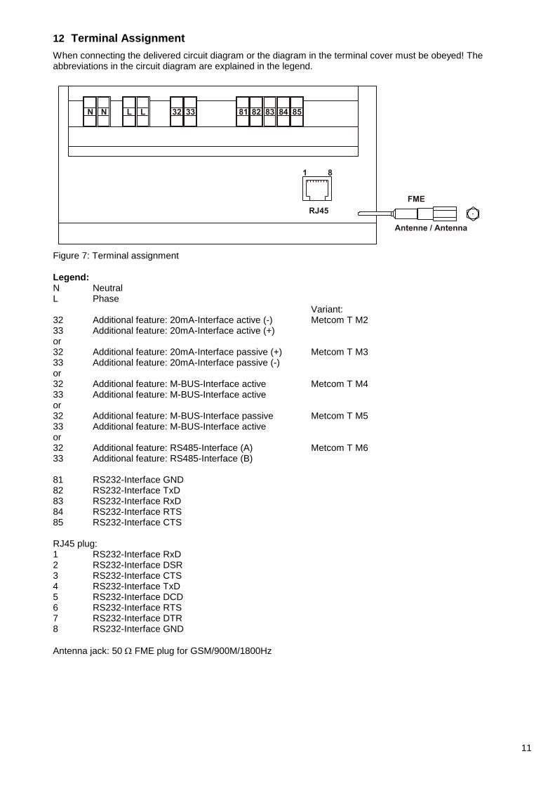
12 Terminal Assignment
When connecting the delivered circuit diagram or the diagram in the terminal cover must be obeyed! The abbreviations in the circuit diagram are explained in the legend.
Figure 7: Terminal assignment
Legend: N Neutral L Phase Variant: 32 Additional feature: 20mA-Interface active (-) Metcom T M2 33 Additional feature: 20mA-Interface active (+) or 32 Additional feature: 20mA-Interface passive (+) Metcom T M3 33 Additional feature: 20mA-Interface passive (-) or 32 Additional feature: M-BUS-Interface active Metcom T M4 33 Additional feature: M-BUS-Interface active or 32 Additional feature: M-BUS-Interface passive Metcom T M5 33 Additional feature: M-BUS-Interface active or 32 Additional feature: RS485-Interface (A) Metcom T M6 33 Additional feature: RS485-Interface (B) 81 RS232-Interface GND 82 RS232-Interface TxD 83 RS232-Interface RxD 84 RS232-Interface RTS 85 RS232-Interface CTS RJ45 plug: 1 RS232-Interface RxD 2 RS232-Interface DSR 3 RS232-Interface CTS 4 RS232-Interface TxD 5 RS232-Interface DCD 6 RS232-Interface RTS 7 RS232-Interface DTR 8 RS232-Interface GND
Antenna jack: 50 FME plug for GSM/900M/1800Hz
03.2011 Subject to change without notice! Bär Industrie-Elektronik GmbH Rathsbergstr. 23 D-90411 Nürnberg www.baer-gmbh.com
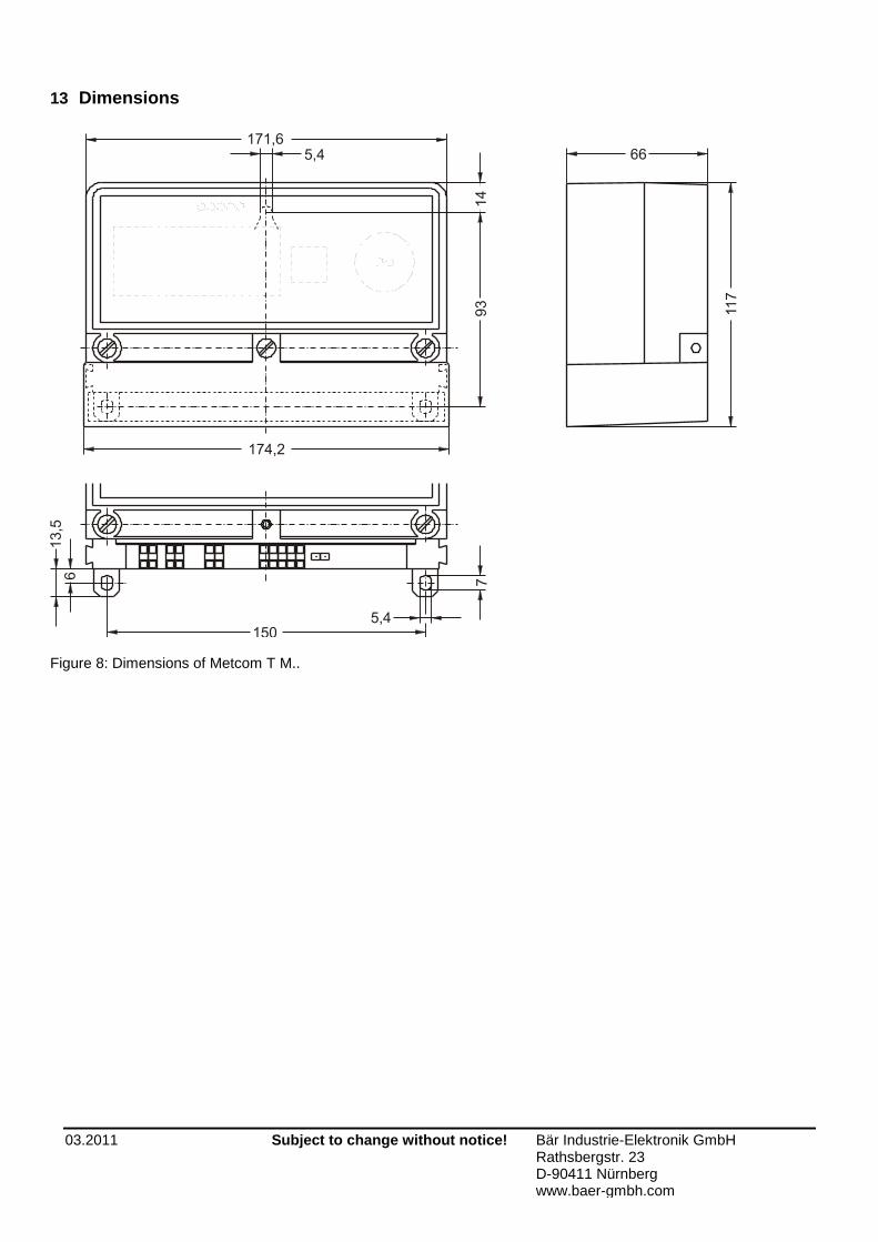
13 Dimensions
Figure 8: Dimensions of Metcom T M..