Embed Size (px)
Citation preview
1
Universitagrave degli Studi di Cassino
e del Lazio Meridional
Facoltagrave di Ingegneria
Associazione Nazionale
Gruppo Misure
Elettriche ed Elettroniche
Lezioni del Corso di
Misure Elettriche
AA 2012-2013
GG MM EE EE
Corso di Laurea Magistrale in Ingegneria Elettrica
Le Misure di Power Quality
2
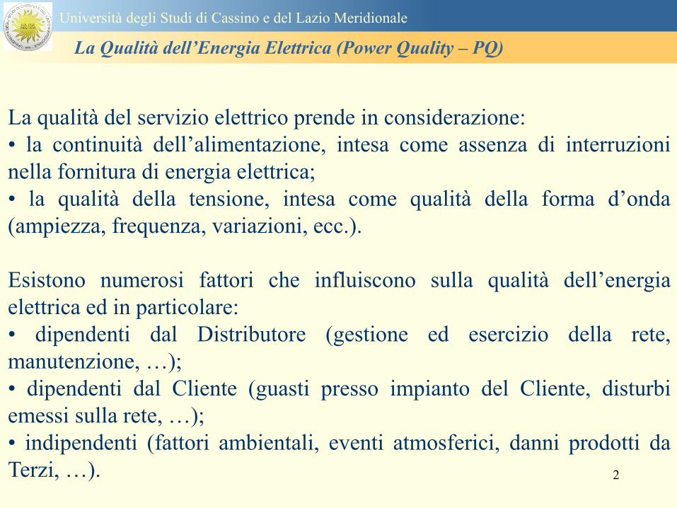
La qualitagrave del servizio elettrico prende in considerazione
bull la continuitagrave dellrsquoalimentazione intesa come assenza di interruzioni
nella fornitura di energia elettrica
bull la qualitagrave della tensione intesa come qualitagrave della forma drsquoonda
(ampiezza frequenza variazioni ecc)
Esistono numerosi fattori che influiscono sulla qualitagrave dellrsquoenergia
elettrica ed in particolare
bull dipendenti dal Distributore (gestione ed esercizio della rete
manutenzione hellip)
bull dipendenti dal Cliente (guasti presso impianto del Cliente disturbi
emessi sulla rete hellip)
bull indipendenti (fattori ambientali eventi atmosferici danni prodotti da
Terzi hellip)
Universitagrave degli Studi di Cassino e del Lazio Meridionale
La Qualitagrave dellrsquoEnergia Elettrica (Power Quality ndash PQ)
3
Contesto Compatibilitagrave Elettromagnetica
Disturbi radiati Disturbi condotti
Disturbo elettromagnetico fenomeno elettromagnetico che puograve degradare la prestazione
di un dispositivo di unrsquoapparecchiatura o di un sistema
Universitagrave degli Studi di Cassino e del Lazio Meridionale
La Qualitagrave dellrsquoEnergia Elettrica (Power Quality ndash PQ)
4
CIRCUITI NON LINEARI
Equivalent circuit of a non-linear load
Ih
Vh
Universitagrave degli Studi di Cassino e del Lazio Meridionale
La Qualitagrave dellrsquoEnergia Elettrica (Power Quality ndash PQ)
5
Power quality
problems
Turn off the mixer love
the monitorrsquos flickering
again
are
usually of
terrestrial
origin
Universitagrave degli Studi di Cassino e del Lazio Meridionale
La Qualitagrave dellrsquoEnergia Elettrica (Power Quality ndash PQ)
6
Universitagrave degli Studi di Cassino e del Lazio Meridionale
La Qualitagrave dellrsquoEnergia Elettrica (Power Quality ndash PQ)
Dobbiamo separare gli eventi di power quality dagli altri
problemi
bullSe avete delle apparecchiature sensibili
bullDisservizi inaspettati e intermittentihellip
bullQualrsquoegrave la causa dei disservizi o guasti
Software bug Cattive connessioni
Errori delloperatore Temperatura
Screpolature nei materiali Umiditagrave
Bolle nellacqua di raffreddamento
ecc ecc
ndashOppure egrave un disturbo power quality
7
Universitagrave degli Studi di Cassino Corso di Fondamenti di Misure
La Qualitagrave dellrsquoEnergia Elettrica (Power Quality ndash PQ)
Tensione costante e pari alla nominale
Frequenza costante e pari alla nominale
Tensioni e correnti sinusoidali
Continuitagrave del servizio
Le condizioni ideali
I ldquodisturbirdquo rappresentano lo scostamento
dei parametri elettrici dai valori ideali e la
non continuitagrave del servizio
La valutazione complessiva di questi
aspetti egrave denominata Power Quality
8
The good
old days bull
bull Ideal
three-phase
system
voltage
Three balanced
ohmic-inductive
single-phase loads
on the three phase
mains
-150A
-100A
-50A
0A
50A
100A
150A
0ms 5ms 10ms 15ms 20ms
t
i
i1 (L1)
i1 (L2)
i1 (L3)
-350V
-250V
-150V
-50V
50V
150V
250V
350V
0ms 5ms 10ms 15ms 20ms
t
u u1 (L1)
u1 (L2)
u1 (L3 )
Universitagrave degli Studi di Cassino e del Lazio Meridionale
La Qualitagrave dellrsquoEnergia Elettrica (Power Quality ndash PQ)
9
Distorsione armonica
Interruzioni del servizio
Abbassamenti di tensione e sovratensioni
Buchi di tensione
Transitori
Frequenza nominale della tensione fornita
Flicker - variazioni rapide della tensione
Squilibrio delle tensioni
Universitagrave degli Studi di Cassino e del Lazio Meridionale
La Qualitagrave dellrsquoEnergia Elettrica (Power Quality ndash PQ)
10
IEC 61000-2-22002 Electromagnetic compatibility (EMC) ndash Part 2-2 Environment ndash
Compatibility levels for low-frequency conducted disturbances and signalling in public
lowvoltage power supply systems
IEC 61000-2-4 Electromagnetic compatibility (EMC) ndash Part 2-4 Environment ndash
Compatibility levels in industrial plants for low-frequency conducted disturbances
IEC 61000-3-8 Electromagnetic compatibility (EMC) ndash Part 3 Limits ndash Section 8 Signalling
on low-voltage electrical installations ndash Emission levels frequency bands and electromagnetic
disturbance levels
IEC 61000-4-42004 Electromagnetic compatibility (EMC) ndash Part 4-4 Testing and
measurement techniques ndash Electrical fast transientburst immunity test
IEC 61000-4-72002 Electromagnetic compatibility (EMC) ndash Part 4-7 Testing and
measurement techniques ndash General guide on harmonics and interharmonics measurements
and instrumentation for power supply systems and equipment connected thereto
IEC 61000-4-302008 Electromagnetic compatibility (EMC) ndash Part 4-30 Testing and
measurement techniques ndash Power quality measurement methods
IEC 61000-4-15 Electromagnetic compatibility (EMC) ndash Part 4 Testing and measurement
techniques ndash Section 15 Flickermeter ndash Functional and design specifications
IEC 61180 (all parts) High-voltage test techniques for low voltage equipment
Normativa di riferimento
Universitagrave degli Studi di Cassino e del Lazio Meridionale
La Qualitagrave dellrsquoEnergia Elettrica (Power Quality ndash PQ)
11
IEC 61000 - 4 ndash 30 Norm
Seri 61000 Electromagnetic Compatibility
International Electrotechnical Commission
Part 4 Test and Measurement Tecniques
Section 30 PQ measurement methods
IEC 61000 - 4 ndash 7 Norm
Section 7 General guide on harmonics
and interharmonics measurements and
instrumentation for power supply
systems and equipment connected
thereto
Part 2 Environment ndashCompatibility levels
Seri 61000 Electromagnetic Compatibility
IEC International Electrotechnical Commission
Section xx details on the application sector
Part 3 Limits
Part 4 Test and Measurement Tecniques
Universitagrave degli Studi di Cassino e del Lazio Meridionale
La Qualitagrave dellrsquoEnergia Elettrica (Power Quality ndash PQ)
12
EN 501602010-07 Caratteristiche della tensione fornita dalle reti pubbliche di distribuzione
dellrsquoenergia elettrica
Descrive e specifica le caratteristiche principali della tensione ai terminali di
alimentazione di un utente della rete pubblica in bassa media e alta tensione in corrente
alternata in normali condizioni di esercizio Essa descrive i limiti o valori entro i quali le
caratteristiche della tensione possono essere attesi ai punti di alimentazione da reti elettriche
pubbliche europee e non descrive la situazione media sperimentata da un singolo utente di rete
Le caratteristiche della tensione fornite nella presente Norma non sono utilizzabili ai fini dei
limiti di EMC o di disturbi condotti nella rete pubblica Esse non sono utilizzabili ai fini di
prescrizioni nelle norme di prodotto o nelle norme per impianti
Normativa di riferimento
Universitagrave degli Studi di Cassino e del Lazio Meridionale
La Qualitagrave dellrsquoEnergia Elettrica (Power Quality ndash PQ)
13
Nel dettaglio la norma EN 50160 definisce i seguenti parametri
1 Frequenza nominale della tensione fornita
2 Ampiezza della tensione di alimentazione
3 Variazioni della tensione di alimentazione
4 Flicker - variazioni rapide della tensione
5 Buchi di tensione
6 Interruzioni della tensione di alimentazione
7 Squilibrio della tensione di alimentazione
8 Tensioni armoniche THD e fino al 25deg ordine
Universitagrave degli Studi di Cassino e del Lazio Meridionale
La Qualitagrave dellrsquoEnergia Elettrica (Power Quality ndash PQ)
14
Si specifica che qualora lrsquoazienda distributrice installi un registratore
della qualitagrave delle caratteristiche della tensione diverse dalle
interruzioni senza preavviso lunghe brevi e transitorie lo strumento
deve essere conforme alla norma tecnica EN 61000-4-30
Richiami nella delibera 042004
dellAUTORITA PER LENERGIA ELETTRICA E IL GAS
Il 30 gennaio 2004 con delibera 404 lrsquoautoritagrave dellrsquoenergia ha indicato tra i vari
argomenti trattati i criteri di misura delle qualitagrave della tensione
Nellrsquoarticolo 39 (pagina 29) viene indicato nel punto 391 e 2 che per la
registrazione di interruzioni senza preavviso lunghe brevi e transitorie occorre
utilizzare un registratore conforme alla CEI EN 50160 In questo caso lo strumento
registratore dice quando e per quanto si ha unrsquointerruzione del servizio ma a tutti gli
effetti NON EFFETTUA UNrsquoOSSERVAZIONE QUALITATIVA dei parametri
Universitagrave degli Studi di Cassino e del Lazio Meridionale
La Qualitagrave dellrsquoEnergia Elettrica (Power Quality ndash PQ)
15
Universitagrave degli Studi di Cassino e del Lazio Meridionale
La Qualitagrave dellrsquoEnergia Elettrica (Power Quality ndash PQ)
16
17
Universitagrave degli Studi di Cassino e del Lazio Meridionale
La Qualitagrave dellrsquoEnergia Elettrica (Power Quality ndash PQ)
CURVA DI TOLLERANZA AI DISTURBI
18
Caratteristiche dellrsquoalimentazione a bassa tensione
Universitagrave degli Studi di Cassino e del Lazio Meridionale
La Qualitagrave dellrsquoEnergia Elettrica (Power Quality ndash PQ)
19
Caratteristiche dellrsquoalimentazione a bassa tensione
Frequenza nominale
La frequenza nominale della tensione fornita deve essere di 50 Hz In condizioni normali
di esercizio il valore medio misurato nellrsquointervallo di 10 secondi deve essere
Per i sistemi con collegamento sincrono ad un sistema interconnesso
1 50 Hz plusmn 1 durante il 95 di un anno
2 50 Hz +4 - 6 durante il 100 di un anno
Per i sistemi senza collegamento sincrono ad un sistema interconnesso
1 50 Hz plusmn 2 durante il 95 di un anno
2 50 Hz plusmn 15 durante il 100 di un anno
Universitagrave degli Studi di Cassino e del Lazio Meridionale
La Qualitagrave dellrsquoEnergia Elettrica (Power Quality ndash PQ)
20
Caratteristiche dellrsquoalimentazione a bassa tensione
Universitagrave degli Studi di Cassino e del Lazio Meridionale
La Qualitagrave dellrsquoEnergia Elettrica (Power Quality ndash PQ)
21
Caratteristiche dellrsquoalimentazione a bassa tensione
Universitagrave degli Studi di Cassino e del Lazio Meridionale
La Qualitagrave dellrsquoEnergia Elettrica (Power Quality ndash PQ)
22
Variazioni della tensione di alimentazione (variazioni lente)
Le variazioni lente sono deviazioni ldquomedierdquo dal valore nominale dellrsquoampiezza della
tensione di consegna entro una fascia predefinita (per esempio del plusmn10) rispetto alla
tensione dichiarata
CAUSE variazione lenta dei carichi e dalla corrispondente azione di regolazione effettuata dai
variatori sotto carico dei trasformatori
Universitagrave degli Studi di Cassino e del Lazio Meridionale
La Qualitagrave dellrsquoEnergia Elettrica (Power Quality ndash PQ)
23
Variazioni della tensione di alimentazione (variazioni rapide)
Le variazioni rapide sono abbassamenti (o aumenti) bruschi di qualche percento della
tensione preesistente generalmente seguiti se abbassamenti da un ritorno (a rampa o di
altra forma) ad un valore intermedio tra quello preesistente e tra il minimo raggiunto
CAUSE commutazione dei carichi (partenza motori in particolare) funzionamento di carichi
con ciclo operativo particolarmente variabile e in qualche caso da manovre in rete (linee
trasformatori condensatori ecc)
Universitagrave degli Studi di Cassino e del Lazio Meridionale
La Qualitagrave dellrsquoEnergia Elettrica (Power Quality ndash PQ)
24
Flicker Il flicker egrave originato dalla fluttuazione della tensione Si definisce fluttuazione di tensione una
serie di variazioni rapide (uguali o diverse) della tensione
Fluttuazioni di tensione che presentano frequenze di modulazione del 50 Hz comprese tra 05 e
40 Hz danno origine al fenomeno del flicker (sfarfallio) ovvero della sensazione visiva
provocata dalle fluttuazioni dellrsquointensitagrave di illuminazione delle lampade
I suoi principali effetti sullrsquouomo possono essere mal di testa irritabilitagrave e fastidio agli occhi
Universitagrave degli Studi di Cassino e del Lazio Meridionale
La Qualitagrave dellrsquoEnergia Elettrica (Power Quality ndash PQ)
25
Universitagrave degli Studi di Cassino e del Lazio Meridionale
La Qualitagrave dellrsquoEnergia Elettrica (Power Quality ndash PQ)
26
La Qualitagrave dellrsquoEnergia Elettrica (Power Quality ndash PQ)
Universitagrave degli Studi di Cassino e del Lazio Meridionale
La Qualitagrave dellrsquoEnergia Elettrica (Power Quality ndash PQ)
27
Universitagrave degli Studi di Cassino e del Lazio Meridionale
La Qualitagrave dellrsquoEnergia Elettrica (Power Quality ndash PQ)
28
Universitagrave degli Studi di Cassino e del Lazio Meridionale
La Qualitagrave dellrsquoEnergia Elettrica (Power Quality ndash PQ)
29
Universitagrave degli Studi di Cassino e del Lazio Meridionale
La Qualitagrave dellrsquoEnergia Elettrica (Power Quality ndash PQ)
30
Universitagrave degli Studi di Cassino e del Lazio Meridionale
La Qualitagrave dellrsquoEnergia Elettrica (Power Quality ndash PQ)
31
Universitagrave degli Studi di Cassino e del Lazio Meridionale
La Qualitagrave dellrsquoEnergia Elettrica (Power Quality ndash PQ)
32
Buchi di tensione Riduzione temporanea della tensione in un punto della rete elettrica sotto una determinata
soglia Se durante un buco la tensione scende sotto una soglia di interruzione lrsquoevento egrave
considerato essere sia un buco che unrsquointerruzione
CAUSE I buchi di tensione sono generalmente dovuti a guasti che sopravvengono negli
impianti utilizzatori o nel sistema di distribuzione pubblico Possono dipendere anche variazioni
di carico lungo la linea
Universitagrave degli Studi di Cassino e del Lazio Meridionale
La Qualitagrave dellrsquoEnergia Elettrica (Power Quality ndash PQ)
33
Interruzioni della tensione di alimentazione Condizione in cui la tensione ad un terminale della rete egrave inferiore allrsquo1 della tensione
nominale per una durata fino a tre minuti (brevi) o maggiori di 3 minuti (lunghe)
Universitagrave degli Studi di Cassino e del Lazio Meridionale
La Qualitagrave dellrsquoEnergia Elettrica (Power Quality ndash PQ)
34
Sovratensioni temporanee alla frequenza di rete fra fasi e terra Le sovratensioni sono sopraelevazioni della tensione conseguenti a modificazioni dello
stato elettrico della rete elettrica
Universitagrave degli Studi di Cassino e del Lazio Meridionale
La Qualitagrave dellrsquoEnergia Elettrica (Power Quality ndash PQ)
35
Armoniche Le armoniche sono tensioni o correnti sinusoidali con frequenza pari ad un multiplo intero
(ordine) della frequenza fondamentale di funzionamento del sistema elettrico la cui
presenza determina una distorsione della forma drsquoonda della tensione di alimentazione
CAUSE In piccola parte dal sistema stesso (trasformatori etc) e per la maggior parte da
apparecchi utilizzatori carichi commutati elettronicamente raddrizzatori convertitori regolatori
in AC cicloconvertitori ecc carichi con caratteristiche non lineari apparecchiature a
saturazione magnetica lampade a scarica forni ad arco saldatrici ad arco trasformatori ecc
bull carichi inseriti e disinseriti da organi di manovra condensatori filtri e motori a induzione
Universitagrave degli Studi di Cassino e del Lazio Meridionale
La Qualitagrave dellrsquoEnergia Elettrica (Power Quality ndash PQ)
36
Armoniche di tensione e corrente ndash Problemi
Vi sono diversi ambiti causati dalle armoniche
bull problemi causati da armoniche di corrente
1048707 sovraccarico del neutro
1048707 aumento delle perdite nei trasformatori
1048707 interventi intempestivi degli interruttori automatici
1048707 aumento dellrsquoeffetto pelle
bull problemi causati da armoniche di tensione
1048707 deformazione della tensione
1048707 disturbi nella coppia dei motori ad induzione
1048707 rumore al passaggio per lo zero
bull problemi causati quando le armoniche di corrente raggiungono lrsquoalimentazione
Universitagrave degli Studi di Cassino e del Lazio Meridionale
La Qualitagrave dellrsquoEnergia Elettrica (Power Quality ndash PQ)
37
38
Universitagrave degli Studi di Cassino e del Lazio Meridionale
La Qualitagrave dellrsquoEnergia Elettrica (Power Quality ndash PQ)
39
Strumentazione ldquohand heldrdquo con display
Universitagrave degli Studi di Cassino e del Lazio Meridionale
La Qualitagrave dellrsquoEnergia Elettrica (Power Quality ndash PQ)
40
Strumentazione ldquohand heldrdquo con display
Universitagrave degli Studi di Cassino e del Lazio Meridionale
La Qualitagrave dellrsquoEnergia Elettrica (Power Quality ndash PQ)
41
Strumentazione da registrazione
Universitagrave degli Studi di Cassino e del Lazio Meridionale
La Qualitagrave dellrsquoEnergia Elettrica (Power Quality ndash PQ)
42
Schema di principio ndash 61000-4-30 copy IEC2008
The electrical quantity to be measured may be either directly accessible as is
generally the case in low-voltage systems or accessible via measurement
transducers
An instrument may include the whole measurement chain In this standard the
normative part does not consider the measurement transducers external to the
instrument and their associated uncertainty
Universitagrave degli Studi di Cassino e del Lazio Meridionale
La Qualitagrave dellrsquoEnergia Elettrica (Power Quality ndash PQ)
43
Universitagrave degli Studi di Cassino Corso di Fondamenti di Misure
La Qualitagrave dellrsquoEnergia Elettrica (Power Quality ndash PQ)
Classi dei metodi di misura - 61000-4-30 copy IEC2008
For each class measurement methods and appropriate performance requirements
are included
Sono definite tre classi A S e B
Class A
This class is used where precise measurements are necessary for example for contractual
applications that may require resolving disputes verifying compliance with standards etc
Any measurements of a parameter carried out with two different instruments complying with
the requirements of Class A when measuring the same signals will produce matching results
within the specified uncertainty for that parameter
Class S
This class is used for statistical applications such as surveys or power quality assessment
possibly with a limited subset of parameters Although it uses equivalent intervals of
measurement as class A the class S processing requirements are lower
Class B
This class is defined in order to avoid making many existing instruments designs obsolete
NOTE Class B methods are not recommended for new designs Readers are advised that Class B may be removed in a
future Edition of this standard
44
Classi dei metodi di misura - 61000-4-30 copy IEC2008
Measurement aggregation over time intervals
CLASS A
The basic measurement time interval for parameter magnitudes (supply voltage harmonics
interharmonics and unbalance) shall be a 10-cycle time interval for a 50 Hz power system
or 12-cycle time interval for a 60 Hz power system
The 1012-cycle measurement shall be re-synchronized at every RTC 10 min tick
The 1012-cycle values are then aggregated over 3 additional intervals
ndash 150180-cycle interval (150 cycles for 50 Hz nominal or 180 cycles for 60 Hz nominal)
ndash 10 min interval
ndash 2 h interval
CLASS S
Same time intervals as Class A
CLASS B
The manufacturer shall specify the number and duration of aggregation time intervals
Universitagrave degli Studi di Cassino e del Lazio Meridionale
La Qualitagrave dellrsquoEnergia Elettrica (Power Quality ndash PQ)
45
Universitagrave degli Studi di Cassino e del Lazio Meridionale
La Qualitagrave dellrsquoEnergia Elettrica (Power Quality ndash PQ)
46
Universitagrave degli Studi di Cassino e del Lazio Meridionale
La Qualitagrave dellrsquoEnergia Elettrica (Power Quality ndash PQ)
Class A
The 10-min aggregated value shall be tagged with the absolute time (for
example 01H1000) The time tag is the time at the conclusion of the 10-min
aggregation
The data for the 10-min time interval shall be aggregated from 1012-cycle time
intervals
Each 10-minute interval shall begin on a UTC 10-min tick The 10-min tick is
also used to re-synchronize the 1012-cycle intervals and the 150180-cycle
intervals
The final 1012-cycle interval(s) in a 10-min aggregation period will typically
overlap in time with the UTC 10-min clock tick Any overlapping 1012-cycle
interval (Overlap 1 in Figure 2) is included in the aggregation of the previous
10-min interval
47
Universitagrave degli Studi di Cassino e del Lazio Meridionale
La Qualitagrave dellrsquoEnergia Elettrica (Power Quality ndash PQ)
48
Universitagrave degli Studi di Cassino e del Lazio Meridionale
La Qualitagrave dellrsquoEnergia Elettrica (Power Quality ndash PQ)
49
Classi dei metodi di misura - 61000-4-30 copy IEC2008
Real time clock (RTC) uncertainty
Sono definite le specifiche per le 3 classi
Flagging concept
During a dip swell or interruption the measurement algorithm for other
parameters (for example frequency measurement) might produce an unreliable
value The flagging concept therefore avoids counting a single event more than
once in different parameters (for example counting a single dip as both a dip and a
frequency variation) and indicates that an aggregated value might be unreliable
Universitagrave degli Studi di Cassino e del Lazio Meridionale
La Qualitagrave dellrsquoEnergia Elettrica (Power Quality ndash PQ)
50
Classi dei metodi di misura - 61000-4-30 copy IEC2008
Power quality parameters - INDICES
Per ogni parametro viene suggerito il metodo di misura per le tre classi e
(soprattutto) le caratteristiche di precisione Per alcuni parametri rimanda a
specifiche norme (ad esempio Flicker e Armonicheinterarmoniche)
Esempio - Power frequency Class A
The frequency reading shall be obtained every 10 s As power frequency may not be exactly 50 Hz or 60
Hz within the 10 s time clock interval the number of cycles may not be an integer number The
fundamental frequency output is the ratio of the number of integral cycles counted during the 10 s time
clock interval divided by the cumulative duration of the integer cycles Before each assessment
harmonics and interharmonics shall be attenuated to minimize the effects of multiple zero crossings
The measurement time intervals shall be non-overlapping Individual cycles that overlap the 10 s time
clock are discarded Each 10 s interval shall begin on an absolute 10 s time clock with uncertainty as
defined in 46
Other techniques that provide equivalent results such as convolution are acceptable
Class S Same as class A
Class B The manufacturer shall specify the process used for frequency measurement
Universitagrave degli Studi di Cassino e del Lazio Meridionale
La Qualitagrave dellrsquoEnergia Elettrica (Power Quality ndash PQ)
51
Classi dei metodi di misura - 61000-4-30 copy IEC2008
Power quality parameters - INDICES
Per ogni parametro viene suggerito il metodo di misura per le tre classi e
(soprattutto) le caratteristiche di precisione Per alcuni parametri rimanda a
specifiche norme (ad esempio Flicker e Armonicheinterarmoniche)
Esempio - Power frequency
Measurement uncertainty and measuring range
ndash Class A
Under the conditions described in 61 the measurement uncertainty shall not exceed
plusmn10 mHz over the measuring ranges 425 Hz ~ 575 Hz 51 Hz ~ 69 Hz
ndash Class S
Under the conditions described in 61 the measurement uncertainty shall not exceed
plusmn50 mHz over the measuring ranges 425 Hz ~ 575 Hz 51 Hz ~ 69 Hz
ndash Class B
The manufacturer shall specify the uncertainty over the measuring ranges 425 Hz ~
575 Hz 51 Hz ~ 69 Hz
Universitagrave degli Studi di Cassino e del Lazio Meridionale
La Qualitagrave dellrsquoEnergia Elettrica (Power Quality ndash PQ)
52
Magnitude of the supply voltage
Measurement method
ndash Class A
The measurement shall be the rms value of the voltage magnitude over
a 10-cycle time interval for 50 Hz power system or 12-cycle time
interval for 60 Hz power system Every 1012-cycle interval shall be
contiguous and not overlapping with adjacent 1012-cycle intervals
except as shown as Overlap 1 in Figure 2
NOTE 1 This specific measurement method is used for quasi-stationary signals and is
not used for the detection and measurement of disturbances dips swells voltage
interruptions and transients
NOTE 2 The rms value includes by definition harmonics interharmonics mains
signalling etc
- Class S same as Class A
Universitagrave degli Studi di Cassino e del Lazio Meridionale
La Qualitagrave dellrsquoEnergia Elettrica (Power Quality ndash PQ)
53
Magnitude of the supply voltage
Measurement uncertainty and measuring range
ndash Class A
Under the conditions described in Clause 6 the measurement uncertainty
shall not exceed plusmn01 of Udin over the range of 10 ~ 150 of Udin
ndash Class S
Under the conditions described in Clause 6 the measurement uncertainty
shall not exceed plusmn05 of Udin over the range of 20 ~ 120 of Udin
Universitagrave degli Studi di Cassino e del Lazio Meridionale
La Qualitagrave dellrsquoEnergia Elettrica (Power Quality ndash PQ)
54
Supply voltage dips and swells
Measurement method
ndash Class A
The basic measurement Urms of a voltage dip and swell shall be the
Urms(frac12) on each measurement channel (see Clause 322)
The cycle duration for Urms(frac12) depends on the frequency The
frequency might be determined by the last non-flagged power frequency
measurement (see Clause 47 and Clause 51) or by any other method
that yields the uncertainty requirements of Clause 6
NOTE 1 The Urms(frac12) value includes by definition harmonics interharmonics mains
signalling voltage etc
NOTE 2 It is important to avoid loss of data when dips and swells occur in a rapid
sequence (for example three events in one second with up to one minute between
sequences may occur when a recloser operates into a sustained fault) If during a rapid
burst the dipswell event characteristics cannot be recorded then a count of events may
be useful
Universitagrave degli Studi di Cassino e del Lazio Meridionale
La Qualitagrave dellrsquoEnergia Elettrica (Power Quality ndash PQ)
55
Supply voltage dips and swells
Detection and evaluation of a voltage dip
Voltage dip detection
The dip threshold is a percentage of either Udin or the sliding voltage
reference Usr (see 525 544) The user shall declare the reference
voltage in use
NOTE ndash On single-phase systems a voltage dip begins when the Urms voltage falls
below the dip threshold and ends when the Urms voltage is equal to or above the dip
threshold plus the hysteresis voltage
ndash On polyphase systems a dip begins when the Urms voltage of one or more channels is
below the dip threshold and ends when the Urms voltage on all measured channels is
equal to or above the dip threshold plus the hysteresis voltage
The dip threshold and the hysteresis voltage are both set by the user according to the
use
Universitagrave degli Studi di Cassino e del Lazio Meridionale
La Qualitagrave dellrsquoEnergia Elettrica (Power Quality ndash PQ)
56
Calculation of a sliding reference voltage
The sliding reference voltage implementation is optional not mandatory
If a sliding reference is chosen for voltage dip or swell detection this
shall be calculated using a first-order filter with a 1-min time constant
This filter is given by
Usr(n) = 09967 times Usr(nndash1) + 00033 times U(1012)rms
where
Usr(n) is the present value of the sliding reference voltage
Usr(nndash1) is the previous value of the sliding reference voltage and
U(1012)rms is the most recent 1012-cycle rms value
When the measurement is started the initial value of the sliding reference voltage is set
to the declared input voltage The sliding reference voltage is updated every 1012-
cycles If a 1012-cycle value is flagged the sliding reference voltage is not updated
and the previous value is used
Universitagrave degli Studi di Cassino e del Lazio Meridionale
La Qualitagrave dellrsquoEnergia Elettrica (Power Quality ndash PQ)
57
Supply voltage dips and swells
Voltage dip evaluation
A voltage dip is characterized by a pair of data either residual voltage
(Ures) or depth and duration
ndash the residual voltage of a voltage dip is the lowest Urms(frac12) value
measured on any channel during the dip
ndash the depth is the difference between the reference voltage (either Udin
or Usr) and the residual voltage It is generally expressed in percentage
of the reference voltage
NOTE 1 During the dip it may be useful to also record the lowest Urms(frac12) on each
channel in addition to the residual voltage of the dip The duration spent below the dip
threshold on each channel may also be useful
Universitagrave degli Studi di Cassino e del Lazio Meridionale
La Qualitagrave dellrsquoEnergia Elettrica (Power Quality ndash PQ)
58
Supply voltage dips and swells
Voltage dip evaluation
NOTE 2 If voltage waveforms are recorded before during and after a
dip useful information about phase angle changes may be available in
the recorded data
The start time of a dip shall be time stamped with the time of the start of
the Urms of the channel that initiated the event and the end time of the
dip shall be the time stamped with the time of the end of the Urms that
ended the event as defined by the threshold plus the hysteresis
The duration of a voltage dip is the time difference between the start
time and the end time of the voltage dip
Universitagrave degli Studi di Cassino e del Lazio Meridionale
La Qualitagrave dellrsquoEnergia Elettrica (Power Quality ndash PQ)
59
Supply voltage dips and swells
Residual voltage and swell voltage magnitude measurement
uncertainty
ndash Class A
The measurement uncertainty shall not exceed plusmn02 of Udin
ndash Class S
The measurement uncertainty shall not exceed plusmn10 of Udin
Universitagrave degli Studi di Cassino e del Lazio Meridionale
La Qualitagrave dellrsquoEnergia Elettrica (Power Quality ndash PQ)
60
Schema di principio ndash 61000-4-7 copy IEC2002
Universitagrave degli Studi di Cassino e del Lazio Meridionale
La Qualitagrave dellrsquoEnergia Elettrica (Power Quality ndash PQ)
61
Universitagrave degli Studi di Cassino e del Lazio Meridionale
La Qualitagrave dellrsquoEnergia Elettrica (Power Quality ndash PQ)
62
Universitagrave degli Studi di Cassino e del Lazio Meridionale
La Qualitagrave dellrsquoEnergia Elettrica (Power Quality ndash PQ)
63
Inter-Armoniche Le inter-armoniche sono tensioni o correnti sinusoidali con frequenza diversa da un
multiplo intero della fondamentale la cui presenza determina una distorsione
(modulazione) della forma donda della tensione di alimentazione
CAUSE dai carichi che assorbono correnti inter-armoniche
- carichi commutati elettronicamente convertitori cascata subsincrona cicloconvertitori regolatori con
controllo a pacchetti di cicli ecc
- carichi con caratteristiche non lineari eo non stazionarie forni ad arco saldatrici ad arco ecc
Universitagrave degli Studi di Cassino e del Lazio Meridionale
La Qualitagrave dellrsquoEnergia Elettrica (Power Quality ndash PQ)
64
Universitagrave degli Studi di Cassino e del Lazio Meridionale
La Qualitagrave dellrsquoEnergia Elettrica (Power Quality ndash PQ)
Un porsquo di esempi e
consigli praticihellip
65
0V
50V
100V
150V
200V
250V
300V
350V
0ms 5ms 10ms 15ms 20ms
t
u
0A
1A
2A
3A
i
0V
50V
100V
150V
200V
250V
300V
350V
0ms 5ms 10ms 15ms 20ms
t
u
0A
1A
2A
3A
i
0V
50V
100V
150V
200V
250V
300V
350V
0ms 5ms 10ms 15ms 20ms
t
u
0A
1A
2A
3A
i
gleichgerichtete
Netzspannung
Kondensator-
spannung
gleichgerichteter
Netzstrom
The situation
today
bull Computed current and voltage profiles when a
230 V 58 W fluorescent lamp with an old-style
electronic ballast is driven on the phase wire of
a typical power distribution system
System voltage 230 V
System frequency 50 Hz
Source resistance 500 mW
Longitudinal induction 904 microH
System impedance 575 mW
Mean dc current 180 mA
Smoothing capacitance220 microF
66
And what about electronic ballasts that are rated over 25W
Introduce electronic power factor correction (PFC)
0V
20V
40V
60V
80V
100V
120V
140V
160V
180V
200V
220V
0deg 15deg 30deg 45deg
u
00A
03A
06A
09A
12A
i
67
Though todayrsquos ballasts are better if
rated gt25 W bull Only
the
small
ones
continu
e to
pollute
just like
PCs
TV sets
do
68
This leads to a number of
previously unknown effects bull 1 Deformed voltage curves
bull 2 Huge inrush current peaks
bull 3 Instrument dependent measured parameters
bull 4 Increased loading of phase conductors
bull 5 Loading and overloading of the neutral conductor
bull 6 Overheating and start-up problems of induction motors
bull 7 Additional stray losses in transformers
bull 8 Repercussions of generators upon the mains
bull 9 Influence of capacitors repercussions upon the mains
and four additional complications in TN-C systems
10 Stray currents in equipotential bonding system magnetic fields
11 Contamination of data streams by stray currents
12 Stray currents in the earthing system corrosion damage
13 Lightning currents in devices and equipment
69
1 Deformed voltage curves
bull in theory
-350V
-300V
-250V
-200V
-150V
-100V
-50V
0V
50V
100V
150V
200V
250V
300V
350V
0 5 10 15 20
t ms
u
System voltage profile when driving
a single-phase load comprising
twenty 58 W energy-saver lamps in
parallel on a typical 230 V power
system
70
and in practice
bull An actual
current profile
bull
bull and
bull a voltage profile
bull
bull recorded in a large storage
dispatch and administrative
building
71
at home or in industrial environments
bull
bull Television 40
W
bull 200 Vdiv 2
Adiv
bull 5 msdiv
Harmonic
spectrum
Frequency
converter
50 Adiv
Phase currents
I1=I2=I3=160 A
IN=295 A
5 msdiv
72
Every periodic waveform can be written
as the infinite sum of sinusoidal waves
-175
-150
-125
-100
-75
-50
-25
0
25
50
75
100
125
150
175
0 5 10 15 20
t ms
i
mA
itot
i1
Synthesis of a triangular current profile 100mA
Content fundamental I = 99 mA Isup2 = 9855 mAsup2
Sum of squares Isup2 = 9855 mAsup2
Root of sum = RMS value I = 99 mA
-175
-150
-125
-100
-75
-50
-25
0
25
50
75
100
125
150
175
0 5 10 15 20
t ms
i
mA
itot
i1
i3
Synthesis of a triangular current profile 100mA
Content fundamental I = 99 mA Isup2 = 9855 mAsup2
Cont 3 rd harmonic I = -11 mA Isup2 = 122 mAsup2
Sum of squares Isup2 = 9977 mAsup2
Root of sum = RMS value I = 100 mA
-175
-150
-125
-100
-75
-50
-25
0
25
50
75
100
125
150
175
0 5 10 15 20
t ms
i
mA
itot
i1
i3
i5
Synthesis of a triangular current profile 100mA
Content fundamental I = 99 mA Isup2 = 9855 mAsup2
Cont 3 rd harmonic I = -11 mA Isup2 = 122 mAsup2
Cont 5 th harmonic I = 4 mA Isup2 = 16 mAsup2
Sum of squares Isup2 = 9993 mAsup2
Root of sum = RMS value I = 100 mA
-175
-150
-125
-100
-75
-50
-25
0
25
50
75
100
125
150
175
0 5 10 15 20
t ms
i
mA
itot
i1
i3
i5
i7
Synthesis of a triangular current profile 100mA
Content fundamental I = 99 mA Isup2 = 9855 mAsup2
Cont 3 rd harmonic I = -11 mA Isup2 = 122 mAsup2
Cont 5 th harmonic I = 4 mA Isup2 = 16 mAsup2
Cont 7 th harmonic I = -2 mA Isup2 = 4 mAsup2
Sum of squares Isup2 = 9997 mAsup2
Root of sum = RMS value I = 100 mA
-175
-150
-125
-100
-75
-50
-25
0
25
50
75
100
125
150
175
0 5 10 15 20
t ms
i
mA
itot i1
i3 i5
i7 i9
Synthesis of a triangular current profile 100mA
Content fundamental I = 99 mA Isup2 = 9855 mAsup2
Cont 3 rd harmonic I = -11 mA Isup2 = 122 mAsup2
Cont 5 th harmonic I = 4 mA Isup2 = 16 mAsup2
Cont 7 th harmonic I = -2 mA Isup2 = 4 mAsup2
Cont 9 th harmonic I = 1 mA Isup2 = 2 mAsup2
Sum of squares Isup2 = 9998 mAsup2
Root of sum = RMS value I = 100 mA
-175
-150
-125
-100
-75
-50
-25
0
25
50
75
100
125
150
175
0 5 10 15 20
t ms
i
mA
itot i1
i3 i5
i7 i9
i11
Synthesis of a triangular current profile 100mA
Content fundamental I = 99 mA Isup2 = 9855 mAsup2
Cont 3 rd harmonic I = -11 mA Isup2 = 122 mAsup2
Cont 5 th harmonic I = 4 mA Isup2 = 16 mAsup2
Cont 7 th harmonic I = -2 mA Isup2 = 4 mAsup2
Cont 9 th harmonic I = 1 mA Isup2 = 2 mAsup2
Cont 11 th harmonic I = -1 mA Isup2 = 1 mAsup2
Sum of squares Isup2 = 9999 mAsup2
Root of sum = RMS value I = 100 mA
-175
-150
-125
-100
-75
-50
-25
0
25
50
75
100
125
150
175
0 5 10 15 20
t ms
i
mA
itot i1
i3 i5
i7 i9
i11 i13
Synthesis of a triangular current profile 100mA
Content fundamental I = 99 mA Isup2 = 9855 mAsup2
Cont 3 rd harmonic I = -11 mA Isup2 = 122 mAsup2
Cont 5 th harmonic I = 4 mA Isup2 = 16 mAsup2
Cont 7 th harmonic I = -2 mA Isup2 = 4 mAsup2
Cont 9 th harmonic I = 1 mA Isup2 = 2 mAsup2
Cont 11 th harmonic I = -1 mA Isup2 = 1 mAsup2
Cont 13 th harmonic I = 1 mA Isup2 = 0 mAsup2
Sum of squares Isup2 = 9999 mAsup2
Root of sum = RMS value I = 100 mA
-175
-150
-125
-100
-75
-50
-25
0
25
50
75
100
125
150
175
0 5 10 15 20
t ms
i
mA
itot i1
i3 i5
i7 i9
i11 i13
i15
Synthesis of a triangular current profile 100mA
Content fundamental I = 99 mA Isup2 = 9855 mAsup2
Cont 3 rd harmonic I = -11 mA Isup2 = 122 mAsup2
Cont 5 th harmonic I = 4 mA Isup2 = 16 mAsup2
Cont 7 th harmonic I = -2 mA Isup2 = 4 mAsup2
Cont 9 th harmonic I = 1 mA Isup2 = 2 mAsup2
Cont 11 th harmonic I = -1 mA Isup2 = 1 mAsup2
Cont 13 th harmonic I = 1 mA Isup2 = 0 mAsup2
Cont 15 th harmonic I = 0 mA Isup2 = 0 mAsup2
Sum of squares Isup2 = 10000 mAsup2
Root of sum = RMS value I = 100 mA
-175
-150
-125
-100
-75
-50
-25
0
25
50
75
100
125
150
175
0 5 10 15 20
t ms
i
mA
itot i1
i3 i5
i7 i9
i11 i13
i15 i17
Synthesis of a triangular current profile 100mA
Content fundamental I = 99 mA Isup2 = 9855 mAsup2
Cont 3 rd harmonic I = -11 mA Isup2 = 122 mAsup2
Cont 5 th harmonic I = 4 mA Isup2 = 16 mAsup2
Cont 7 th harmonic I = -2 mA Isup2 = 4 mAsup2
Cont 9 th harmonic I = 1 mA Isup2 = 2 mAsup2
Cont 11 th harmonic I = -1 mA Isup2 = 1 mAsup2
Cont 13 th harmonic I = 1 mA Isup2 = 0 mAsup2
Cont 15 th harmonic I = 0 mA Isup2 = 0 mAsup2
Cont 17 th harmonic I = 0 mA Isup2 = 0 mAsup2
Sum of squares Isup2 = 10000 mAsup2
Root of sum = RMS value I = 100 mA
73
whose frequencies called harmonics are
integer multiples of the fundamental frequency
-175
-150
-125
-100
-75
-50
-25
0
25
50
75
100
125
150
175
0 5 10 15 20
t ms
i
mA
itot
i1
Synthesis of a rectangular current profile 100mA
Content fundamental I = 90 mA Isup2 = 8106 mAsup2
Sum of squares Isup2 = 8106 mAsup2
Root of sum = RMS value I = 90 mA
-175
-150
-125
-100
-75
-50
-25
0
25
50
75
100
125
150
175
0 5 10 15 20
t ms
i
mA
itot
i1
i3
Synthesis of a rectangular current profile 100mA
Content fundamental I = 90 mA Isup2 = 8106 mAsup2
Cont 3 rd harmonic I = 30 mA Isup2 = 901 mAsup2
Sum of squares Isup2 = 9006 mAsup2
Root of sum = RMS value I = 95 mA
-175
-150
-125
-100
-75
-50
-25
0
25
50
75
100
125
150
175
0 5 10 15 20
t ms
i
mA
itot
i1
i3
i5
Synthesis of a rectangular current profile 100mA
Content fundamental I = 90 mA Isup2 = 8106 mAsup2
Cont 3 rd harmonic I = 30 mA Isup2 = 901 mAsup2
Cont 5 th harmonic I = 18 mA Isup2 = 324 mAsup2
Sum of squares Isup2 = 9331 mAsup2
Root of sum = RMS value I = 97 mA
-175
-150
-125
-100
-75
-50
-25
0
25
50
75
100
125
150
175
0 5 10 15 20
t ms
i
mA
itot
i1
i3
i5
i7
Synthesis of a rectangular current profile 100mA
Content fundamental I = 90 mA Isup2 = 8106 mAsup2
Cont 3 rd harmonic I = 30 mA Isup2 = 901 mAsup2
Cont 5 th harmonic I = 18 mA Isup2 = 324 mAsup2
Cont 7 th harmonic I = 13 mA Isup2 = 165 mAsup2
Sum of squares Isup2 = 9496 mAsup2
Root of sum = RMS value I = 97 mA
-175
-150
-125
-100
-75
-50
-25
0
25
50
75
100
125
150
175
0 5 10 15 20
t ms
i
mA
itot i1
i3 i5
i7 i9
Synthesis of a rectangular current profile 100mA
Content fundamental I = 90 mA Isup2 = 8106 mAsup2
Cont 3 rd harmonic I = 30 mA Isup2 = 901 mAsup2
Cont 5 th harmonic I = 18 mA Isup2 = 324 mAsup2
Cont 7 th harmonic I = 13 mA Isup2 = 165 mAsup2
Cont 9 th harmonic I = 10 mA Isup2 = 100 mAsup2
Sum of squares Isup2 = 9596 mAsup2
Root of sum = RMS value I = 98 mA
-175
-150
-125
-100
-75
-50
-25
0
25
50
75
100
125
150
175
0 5 10 15 20
t ms
i
mA
itot i1
i3 i5
i7 i9
i11
Synthesis of a rectangular current profile 100mA
Content fundamental I = 90 mA Isup2 = 8106 mAsup2
Cont 3 rd harmonic I = 30 mA Isup2 = 901 mAsup2
Cont 5 th harmonic I = 18 mA Isup2 = 324 mAsup2
Cont 7 th harmonic I = 13 mA Isup2 = 165 mAsup2
Cont 9 th harmonic I = 10 mA Isup2 = 100 mAsup2
Cont 11 th harmonic I = 8 mA Isup2 = 67 mAsup2
Sum of squares Isup2 = 9663 mAsup2
Root of sum = RMS value I = 98 mA
-175
-150
-125
-100
-75
-50
-25
0
25
50
75
100
125
150
175
0 5 10 15 20
t ms
i
mA
itot i1
i3 i5
i7 i9
i11 i13
Synthesis of a rectangular current profile 100mA
Content fundamental I = 90 mA Isup2 = 8106 mAsup2
Cont 3 rd harmonic I = 30 mA Isup2 = 901 mAsup2
Cont 5 th harmonic I = 18 mA Isup2 = 324 mAsup2
Cont 7 th harmonic I = 13 mA Isup2 = 165 mAsup2
Cont 9 th harmonic I = 10 mA Isup2 = 100 mAsup2
Cont 11 th harmonic I = 8 mA Isup2 = 67 mAsup2
Cont 13 th harmonic I = 7 mA Isup2 = 48 mAsup2
Sum of squares Isup2 = 9711 mAsup2
Root of sum = RMS value I = 99 mA
-175
-150
-125
-100
-75
-50
-25
0
25
50
75
100
125
150
175
0 5 10 15 20
t ms
i
mA
itot i1
i3 i5
i7 i9
i11 i13
i15
Synthesis of a rectangular current profile 100mA
Content fundamental I = 90 mA Isup2 = 8106 mAsup2
Cont 3 rd harmonic I = 30 mA Isup2 = 901 mAsup2
Cont 5 th harmonic I = 18 mA Isup2 = 324 mAsup2
Cont 7 th harmonic I = 13 mA Isup2 = 165 mAsup2
Cont 9 th harmonic I = 10 mA Isup2 = 100 mAsup2
Cont 11 th harmonic I = 8 mA Isup2 = 67 mAsup2
Cont 13 th harmonic I = 7 mA Isup2 = 48 mAsup2
Cont 15 th harmonic I = 6 mA Isup2 = 36 mAsup2
Sum of squares Isup2 = 9747 mAsup2
Root of sum = RMS value I = 99 mA
-175
-150
-125
-100
-75
-50
-25
0
25
50
75
100
125
150
175
0 5 10 15 20
t ms
i
mA
itot i1
i3 i5
i7 i9
i11 i13
i15 i17
Synthesis of a rectangular current profile 100mA
Content fundamental I = 90 mA Isup2 = 8106 mAsup2
Cont 3 rd harmonic I = 30 mA Isup2 = 901 mAsup2
Cont 5 th harmonic I = 18 mA Isup2 = 324 mAsup2
Cont 7 th harmonic I = 13 mA Isup2 = 165 mAsup2
Cont 9 th harmonic I = 10 mA Isup2 = 100 mAsup2
Cont 11 th harmonic I = 8 mA Isup2 = 67 mAsup2
Cont 13 th harmonic I = 7 mA Isup2 = 48 mAsup2
Cont 15 th harmonic I = 6 mA Isup2 = 36 mAsup2
Cont 17 th harmonic I = 5 mA Isup2 = 28 mAsup2
Sum of squares Isup2 = 9775 mAsup2
Root of sum = RMS value I = 99 mA
74
Even far better simulations are
available free of charge at
bull wwwpowerstandardscomMcEachern
75
-4A
-3A
-2A
-1A
0A
1A
2A
3A
4A
0ms 5ms 10ms 15ms 20ms
t
i
-4A
-3A
-2A
-1A
0A
1A
2A
3A
4A
0ms 5ms 10ms 15ms 20ms
t
i
Applying the Fourier
analysis to a real PC
current does not work
directly
bull
bull but it can be
modelled by a similar
triangular curve in
which not all of the
higher harmonics
have been included
Triangular current profile of
the same amplitude and a
pulse duty cycle of 17
Input current of a PC
with monitor
76
Analysis of the model triangular waveform
-400
-350
-300
-250
-200
-150
-100
-50
0
50
100
150
200
250
300
350
400
0 5 10 15 20
t ms
iI
itot(t) L1 [A] i1(t) L1 [A]
i3(t) L1 [A] i5(t) L1 [A]
i7(t) L1 [A] i9(t) L1 [A]
i11(t) L1 [A] i13(t) L1 [A]
i15(t) L1 [A] i17(t) L1 [A]
77
M3
Harmonics
Energy
(active
power)
L1
L2
L3
N
PE
Important
bull Harmonics are created within the loads
themselves and can flow ldquoupstreamrdquo to
contaminate the power system
78
-6A
-5A
-4A
-3A
-2A
-1A
0A
1A
2A
3A
4A
5A
6A
0ms 5ms 10ms 15ms 20ms
t
i
Squared values
Without
Fundamental 502 mA 251986 mAsup2 the fundamental
3rd harmonic -479 mA 229000 mAsup2 229000 mAsup2
5th harmonic 434 mA 188595 mAsup2 188595 mAsup2
7th harmonic -374 mA 139903 mAsup2 139903 mAsup2
9th harmonic 304 mA 92527 mAsup2 92527 mAsup2
11th harmonic -232 mA 53671 mAsup2 53671 mAsup2
13th harmonic 163 mA 26600 mAsup2 26600 mAsup2
15th harmonic -104 mA 10780 mAsup2 10780 mAsup2
17th harmonic 57 mA 3299 mAsup2 3299 mAsup2
Sum of the squares 996362 mAsup2 744377 mAsup2
Root thereof 998 mAeff THD = 863 mA
What actually is THD Example shown here triangular current
profile with an rms current of 1000 mA
and a pulse duty cycle of 17
THDr (root mean square) = 863mA1000mA = 86
THDf (fundamental) = 863mA502mA = 172
79
Effect on phase-to-neutral
and phase-to-phase voltages
bull Recorded
on June
30 2002
230 p
m
bull What
was the
matter
then
bull The
soccer
final
Germany
vs
Brazil
80
The triple-N harmonics drive
a circulating current in the
delta winding of a distribution
transformer
bull but the
bull voltage harmonics
propagate into the next
low-voltage power
distribution system
81 0V
50V
100V
150V
200V
250V
300V
350V
400V
450V
500V
550V
0 10 20 30 40 50
t ms
u
0A
10A
20A
30A
40A
50A
60A
70A
80A
90A
100A
110A
120A
130A
140A
150A
i
Switching on just as supply voltage passes through zero
0V
50V
100V
150V
200V
250V
300V
350V
400V
450V
500V
550V
0 10 20 30 40 50
t ms
u
0A
10A
20A
30A
40A
50A
60A
70A
80A
90A
100A
110A
120A
130A
140A
150A
i
Switching on just as supply voltage is at its peak
2 Huge inrush current peaks
ndash in theory
82
and in practice
bull Inrush current of a
compact energy-
saver lamp and its
effect on the system
voltage (recorded at
the Technical
University of
Budapest)
bull
83
enables us to infer what
happens when run by a
normal three-phase supply
The same fluorescent lamp
with a magnetic ballast
bull The behaviour measured
when connected to
a dc supply
bull
Behaviour of a 58 W fluorescent lamp connected to a dc
supply
0
20
40
60
80
100
120
140
160
180
200
0 200 400 600 800 1000 1200
i mA
u
V
Measurement
Behaviour of a 58 W fluorescent lamp connected to a dc
supply
0
20
40
60
80
100
120
140
160
180
200
0 200 400 600 800 1000 1200
i mA
u
V
MeasurementCalculation
-350
-300
-250
-200
-150
-100
-50
0
50
100
150
200
250
300
350
0 5 10 15 20
t ms
u
V
-10
-08
-06
-04
-02
00
02
04
06
08
10
i
A
Systems voltage
Current
-350
-300
-250
-200
-150
-100
-50
0
50
100
150
200
250
300
350
0 5 10 15 20
t ms
u
V
-10
-08
-06
-04
-02
00
02
04
06
08
10
i
A
Systems voltage
Lamp voltage
Current
84
Warning ldquoCompensationrdquo is not
always what you think it is
bull Distinguish
between
bull Reactive
power
compensatio
n
aka power
factor
correction
Remedial
measure
Parallel (or
sometimes series)
compensation
using capacitors
Filter circuits
tuned to the
individual harmonic
frequencies
Harmonic
compensation
85
5 (Over)loading the neutral conductor
bull Magnetic ballast Old-style electronic ballast
-25A
-20A
-15A
-10A
-05A
00A
05A
10A
15A
20A
25A
0 5 10 15 20
t ms i
i(t) N
-25A
-20A
-15A
-10A
-05A
00A
05A
10A
15A
20A
25A
0 5 10 15 20
t ms
i
i(t) N
-25A
-20A
-15A
-10A
-05A
00A
05A
10A
15A
20A
25A
0 5 10 15 20
t ms
i
i(t) L1 i(t) L2 i(t) L3
-25A
-20A
-15A
-10A
-05A
00A
05A
10A
15A
20A
25A
0 5 10 15 20
t ms
i
i(t) L1
i(t) L2
i(t) L3
86
Adding the 3rd
harmonics
in the
neutral
wire
-150-100-50
050
100150
0deg 30deg 60deg 90deg 120deg 150deg 180deg 210deg 240deg 270deg 300deg 330deg 360deg
L1
-150-100-50
050
100150
0deg 30deg 60deg 90deg 120deg 150deg 180deg 210deg 240deg 270deg 300deg 330deg 360deg
L2
-150-100-50
050
100150
0deg 30deg 60deg 90deg 120deg 150deg 180deg 210deg 240deg 270deg 300deg 330deg 360deg
L3
-450-400-350-300-250-200-150-100-50
050
100150200250300350400450
0deg 30deg 60deg 90deg 120deg 150deg 180deg 210deg 240deg 270deg 300deg 330deg 360deg
f
iicirc
N
Physics dictates
that at any
moment in time
the phase and
neutral currents
must sum to zero
87
Effect on a three-phase ac motor
appears almost identical
bull The same motor is being
driven
simultaneously in
these three modes
homopolar system
zero-sequence system
direct system
positive-sequence system
inverse system
negative-sequence system
88
The transformer
influences the load
89
but the load also effects
the transformer
Total transformer loss is
2
)()(
nom
nomCunomFeLossI
IPPP
While total transformer loss really is
2
)(
2
)(
2
)(
nomnom
nomad
nom
nomCu
nom
nomFeLossI
I
f
fP
I
IP
U
UPP
90
6 ldquosupplementaryrdquo additional losses
in transformers
can be calculated rapidly
using the following two
simple formulae 50
2
2
1
2
11
Nn
n
nqh
I
In
I
I
e
eK
50
1
2
1
1
50
1
2
Nn
n
nNn
n
nI
IIII
where
Oh well
perhaps a practical
example is clearer
1000 compact 11W
(15VA) energy-saver
lamps powered by a
15kVA transformer
uSC=4 Pa=01PCu
Harmonics of an Osram Dulux 11W
CFL and a serial impedance of
R =291Ω amp X L=113Ω
U U sup2 I L I Lsup2 P aP Cu
n V Vsup2 mA mAsup2
1 2302 529920 485 23523 56
3 83 689 371 13764 295
5 107 1145 203 4121 245
7 43 185 53 281 33
9 11 12 30 90 17
11 23 53 38 144 42
13 10 10 15 23 09
15 06 04 15 23 12
17 11 12 15 23 15
19 05 03 09 08 07
21 05 03 13 17 18
23 06 04 08 06 08
25 04 02 06 04 05
27 06 04 08 06 11
29 04 02 05 03 05
31 03 01 05 03 06
33 03 01 05 03 06
35 03 01 04 02 05
37 03 01 04 02 05
39 03 01 03 01 03
41 01 00 03 01 04
43 02 00 02 00 02
45 01 00 02 00 02
47 01 00 02 00 02
49 01 00 01 00 01
51 01 00 01 00 01
P aP Cu = 814814
etc
etc
91
Harmonics measurement on an
Osram Dulux 11W compact
fluorescent lamp
U U sup2 I L I Lsup2 P addP Cu
n V Vsup2 mA mAsup2
1 2327 541493 489 23912 37
3 06 04 391 15288 215
5 44 194 264 6970 273
7 23 53 200 4000 307
9 01 00 192 3686 467
11 01 00 166 2756 522
13 01 00 127 1613 427
15 01 00 110 1210 426
17 01 00 102 1040 471
19 01 00 87 757 428
21 01 00 77 593 409
23 01 00 73 533 441
25 01 00 61 372 364
27 01 00 49 240 274
29 01 00 42 176 232
31 01 00 36 130 195
33 01 00 30 90 153
35 01 00 33 109 209
37 01 00 31 96 206
39 01 00 25 63 149
41 01 00 25 63 164
43 01 00 25 63 181
45 01 00 19 36 114
47 01 00 18 32 112
49 01 00 19 36 136
51 01 00 16 26 104
P aP Cu = 7017
To some extent
the transformer
protects itself
bull Always remember to
consider it
bull If the influence of the
transformer upon the load
did not exist then the
influence of the load upon
the transformer would be
nearly 9 times as high
7017
etc
etc
92
Rule of thumb Select transformers 35
larger than specification by apparent
power would require
bull This suffices to err
on the safe side
even in the worst
case and can
hardly ever be
wrong since
maximum
efficiency always
lies between 25
and 50 of rated
load
Efficiency of a 1 MVA transformer plotted against loading
985
986
987
988
989
990
991
992
993
994
0 25 50 75 100 125
Relative load h
Design with max Cu loss and min Fe loss
Design with min Cu loss and max Fe loss
1 MVA oil transformer according to HD 428
93
Measured response of an 11 W
fluorescent lamp operated with a
magnetic ballast
94
We are
dealing with
a complex
problem
bull These
effects
are not
isolated
but are
mutuall
y inter-
depende
nt
Effects 2 3 and 5 can be demonstrated
on DKIrsquos display panel
95
A conventional approximately resistive-
inductive load
mA
N L1 L2 L3
Two conventional approximately
resistive-inductive loads Three conventional approximately
resistive-inductive loads
96
A modern electronic load
mA
N
Two modern electronic loads Three modern electronic loads
L1 L2 L3
97
Discoveries on a
refurbished
junction box
System voltage
(as trigger
signal)
Current in the
earthing
conductor
between the
consumer unit
and the
bonding
busbar
98
The TN-C system that was perfectly
adequate some years ago is unable to meet
present-day requirements
-6
-4
-2
0
2
4
6
0 5 10 15 20
t ms
i
A
-350
-300
-250
-200
-150
-100
-50
0
50
100
150
200
250
300
350
0 5 10 15 20
t ms
u
V
99
ldquoTHFrdquo
(third harmonic
filter) made in
Finland
In certain situations this affordable
filter can be of help
German
version ldquoTHXrdquo
100
0Ω
5 Ω
1 0 Ω
1 5 Ω
2 0 Ω
2 5 Ω
3 0 Ω
3 5 Ω
4 0 Ω
0Hz 50Hz 100Hz 150Hz 200Hz 250Hz 300Hz
f
Z
-90deg
-75deg
-60deg
-45deg
-30deg
-15deg
0deg
15deg
30deg
45deg
60deg
75deg
90deg
φ
Reactorreactance
Capacitorreactance
Parallelimpedace
Phase angle
Data and frequency response
of the filter
bull 1320 microF
bull 875
14 mW microH
101
The filter in use
bull In a nursery running sodium vapour lamps (500 kW)
In a typical office and administrative building
102
The EMC Transformer from Switzerland
7 The effects of stray magnetic fields
in TN-C systems
bull ldquoWhen we build transformers the first thing we focus on is complying with our customersrsquo
requirements and only then on complying with standards Why Because it is customer
needs and not standards that offer real scope for product innovationrdquo
103
8 In a TN-C system problems arise from data
streams and working currents mixing
bull Others who
have drawn
attention to
this source of
data
transmission
errors include
engineering
and insurance
companies experts
consultants and many
others besides
104
9 Increased corrosive damage
bull This (once) galvanized steel strip ndash the earth
electrode of a TN-C-S system ndash was located close
to the transformer station
Side facing
transformer
station
Side facing
transformer
station
Side facing away
from transformer
station
Side facing away
from transformer
station
105
bull WRONG RIGHT
Working currents have no place
in earthing systems and
protective conductors
106
10 Lightning currents
107
Which bridge to
cross which bridge to
burn
Sometimes you just donlsquot
believe what you see
This one will soon
look rather charred
IEC 60364-5-54
54343 If from any point of the installation the neutral and protective
functions are provided by separate conductors it is not permitted to
connect the neutral conductor to any other earthed part of the
installation
108
Well then the rest is no longer a
miracle
109
110
111
Another means of (over)loading the
neutral conductor
bull dc currents
Original ldquoFakerdquo
112
and their
effects U = 2285 V
I = 92 mA
P = 182 W
S = 209 VA
Q = 103 VAr
LF = 087
cos φ = 099
U = 2243 V
I = 126 A
P = 380 W
S = 2860 VA
Q = 2830 VAr
No-load current in a
toroidal-core
transformer
200 VA
-350-300
-250-200
-150-100
-500
50
100150
200250
300350
0 10 20 30 40
t ms
u
V
-12
-10
-8
-6
-4
-2
0
2
4
6
8
10
12
i
mA
Voltage
Current
No-load current in a toroidal-core
transformer 200 VA when
running a 1500 W
hairdryer at
half-power
in parallel
-350-300
-250-200
-150-100
-500
50
100150
200250
300350
0 5 10 15 20 25 30 35 40
t ms
u
V
-6
-5
-4
-3
-2
-1
0
1
2
3
4
5
6
i
A
Voltage
Current
113
The later models donlsquot do it any more
The EN 61000-3-2 has at least managed
to put an end to this approach
Domestic appliances Max 105 A of 2nd harmonic
114
An electrical engineering wonder
dc current generates ac voltage
115
Spicing things up with a pinch of HF
electronic halogen lamp transformers
116
Decorative HF reactors
117
Current and power loss as a function of voltage
00
02
04
06
08
10
12
14
16
18
0 40 80 120 160 200 240
U V
I
A
0
20
40
60
80
100
120
PV
W
I [A]
Pv [W]
Power loss capacitor voltage
and total voltage as a function of current
0
50
100
150
200
250
300
350
400
450
000 025 050 075 100 125 150
I A
U
V
0
5
10
15
20
25
30
35
40
45
50
PV
W
Utot [V] Eff
UR [V] Eff
Pv [W]
The passive
harmonic filter
made of readily
available
components
bull is both
reliable
118
and effective
bull befor
e
bull after
119
Half the solution has already been implemented
120
And if thatrsquos not enough
bull Passive filter circuits will do it
121
So what do we need to do
bull In low-voltage power distribution systems
Do not use cables in which the neutral or protective earth conductor has a
reduced cross-section
Use only 5-core cable Do not install TN-C- or TN-C-S systems
Be generous when dimensioning conductor cross-sections This helps to
reduce line voltage drops and thus reduces the effect of current distortions on
the voltage as well as lowering energy losses (see VDE 0298 Part 100)
Generously dimensioned conductors will have no problem coping with any
future increase in demand
Only use measuring instruments that display the true root mean square value
(TRMS meters)
In medium-voltage power distribution systems
Use a varied mix of distribution transformers with different vector groups
2
La qualitagrave del servizio elettrico prende in considerazione
bull la continuitagrave dellrsquoalimentazione intesa come assenza di interruzioni
nella fornitura di energia elettrica
bull la qualitagrave della tensione intesa come qualitagrave della forma drsquoonda
(ampiezza frequenza variazioni ecc)
Esistono numerosi fattori che influiscono sulla qualitagrave dellrsquoenergia
elettrica ed in particolare
bull dipendenti dal Distributore (gestione ed esercizio della rete
manutenzione hellip)
bull dipendenti dal Cliente (guasti presso impianto del Cliente disturbi
emessi sulla rete hellip)
bull indipendenti (fattori ambientali eventi atmosferici danni prodotti da
Terzi hellip)
Universitagrave degli Studi di Cassino e del Lazio Meridionale
La Qualitagrave dellrsquoEnergia Elettrica (Power Quality ndash PQ)
3
Contesto Compatibilitagrave Elettromagnetica
Disturbi radiati Disturbi condotti
Disturbo elettromagnetico fenomeno elettromagnetico che puograve degradare la prestazione
di un dispositivo di unrsquoapparecchiatura o di un sistema
Universitagrave degli Studi di Cassino e del Lazio Meridionale
La Qualitagrave dellrsquoEnergia Elettrica (Power Quality ndash PQ)
4
CIRCUITI NON LINEARI
Equivalent circuit of a non-linear load
Ih
Vh
Universitagrave degli Studi di Cassino e del Lazio Meridionale
La Qualitagrave dellrsquoEnergia Elettrica (Power Quality ndash PQ)
5
Power quality
problems
Turn off the mixer love
the monitorrsquos flickering
again
are
usually of
terrestrial
origin
Universitagrave degli Studi di Cassino e del Lazio Meridionale
La Qualitagrave dellrsquoEnergia Elettrica (Power Quality ndash PQ)
6
Universitagrave degli Studi di Cassino e del Lazio Meridionale
La Qualitagrave dellrsquoEnergia Elettrica (Power Quality ndash PQ)
Dobbiamo separare gli eventi di power quality dagli altri
problemi
bullSe avete delle apparecchiature sensibili
bullDisservizi inaspettati e intermittentihellip
bullQualrsquoegrave la causa dei disservizi o guasti
Software bug Cattive connessioni
Errori delloperatore Temperatura
Screpolature nei materiali Umiditagrave
Bolle nellacqua di raffreddamento
ecc ecc
ndashOppure egrave un disturbo power quality
7
Universitagrave degli Studi di Cassino Corso di Fondamenti di Misure
La Qualitagrave dellrsquoEnergia Elettrica (Power Quality ndash PQ)
Tensione costante e pari alla nominale
Frequenza costante e pari alla nominale
Tensioni e correnti sinusoidali
Continuitagrave del servizio
Le condizioni ideali
I ldquodisturbirdquo rappresentano lo scostamento
dei parametri elettrici dai valori ideali e la
non continuitagrave del servizio
La valutazione complessiva di questi
aspetti egrave denominata Power Quality
8
The good
old days bull
bull Ideal
three-phase
system
voltage
Three balanced
ohmic-inductive
single-phase loads
on the three phase
mains
-150A
-100A
-50A
0A
50A
100A
150A
0ms 5ms 10ms 15ms 20ms
t
i
i1 (L1)
i1 (L2)
i1 (L3)
-350V
-250V
-150V
-50V
50V
150V
250V
350V
0ms 5ms 10ms 15ms 20ms
t
u u1 (L1)
u1 (L2)
u1 (L3 )
Universitagrave degli Studi di Cassino e del Lazio Meridionale
La Qualitagrave dellrsquoEnergia Elettrica (Power Quality ndash PQ)
9
Distorsione armonica
Interruzioni del servizio
Abbassamenti di tensione e sovratensioni
Buchi di tensione
Transitori
Frequenza nominale della tensione fornita
Flicker - variazioni rapide della tensione
Squilibrio delle tensioni
Universitagrave degli Studi di Cassino e del Lazio Meridionale
La Qualitagrave dellrsquoEnergia Elettrica (Power Quality ndash PQ)
10
IEC 61000-2-22002 Electromagnetic compatibility (EMC) ndash Part 2-2 Environment ndash
Compatibility levels for low-frequency conducted disturbances and signalling in public
lowvoltage power supply systems
IEC 61000-2-4 Electromagnetic compatibility (EMC) ndash Part 2-4 Environment ndash
Compatibility levels in industrial plants for low-frequency conducted disturbances
IEC 61000-3-8 Electromagnetic compatibility (EMC) ndash Part 3 Limits ndash Section 8 Signalling
on low-voltage electrical installations ndash Emission levels frequency bands and electromagnetic
disturbance levels
IEC 61000-4-42004 Electromagnetic compatibility (EMC) ndash Part 4-4 Testing and
measurement techniques ndash Electrical fast transientburst immunity test
IEC 61000-4-72002 Electromagnetic compatibility (EMC) ndash Part 4-7 Testing and
measurement techniques ndash General guide on harmonics and interharmonics measurements
and instrumentation for power supply systems and equipment connected thereto
IEC 61000-4-302008 Electromagnetic compatibility (EMC) ndash Part 4-30 Testing and
measurement techniques ndash Power quality measurement methods
IEC 61000-4-15 Electromagnetic compatibility (EMC) ndash Part 4 Testing and measurement
techniques ndash Section 15 Flickermeter ndash Functional and design specifications
IEC 61180 (all parts) High-voltage test techniques for low voltage equipment
Normativa di riferimento
Universitagrave degli Studi di Cassino e del Lazio Meridionale
La Qualitagrave dellrsquoEnergia Elettrica (Power Quality ndash PQ)
11
IEC 61000 - 4 ndash 30 Norm
Seri 61000 Electromagnetic Compatibility
International Electrotechnical Commission
Part 4 Test and Measurement Tecniques
Section 30 PQ measurement methods
IEC 61000 - 4 ndash 7 Norm
Section 7 General guide on harmonics
and interharmonics measurements and
instrumentation for power supply
systems and equipment connected
thereto
Part 2 Environment ndashCompatibility levels
Seri 61000 Electromagnetic Compatibility
IEC International Electrotechnical Commission
Section xx details on the application sector
Part 3 Limits
Part 4 Test and Measurement Tecniques
Universitagrave degli Studi di Cassino e del Lazio Meridionale
La Qualitagrave dellrsquoEnergia Elettrica (Power Quality ndash PQ)
12
EN 501602010-07 Caratteristiche della tensione fornita dalle reti pubbliche di distribuzione
dellrsquoenergia elettrica
Descrive e specifica le caratteristiche principali della tensione ai terminali di
alimentazione di un utente della rete pubblica in bassa media e alta tensione in corrente
alternata in normali condizioni di esercizio Essa descrive i limiti o valori entro i quali le
caratteristiche della tensione possono essere attesi ai punti di alimentazione da reti elettriche
pubbliche europee e non descrive la situazione media sperimentata da un singolo utente di rete
Le caratteristiche della tensione fornite nella presente Norma non sono utilizzabili ai fini dei
limiti di EMC o di disturbi condotti nella rete pubblica Esse non sono utilizzabili ai fini di
prescrizioni nelle norme di prodotto o nelle norme per impianti
Normativa di riferimento
Universitagrave degli Studi di Cassino e del Lazio Meridionale
La Qualitagrave dellrsquoEnergia Elettrica (Power Quality ndash PQ)
13
Nel dettaglio la norma EN 50160 definisce i seguenti parametri
1 Frequenza nominale della tensione fornita
2 Ampiezza della tensione di alimentazione
3 Variazioni della tensione di alimentazione
4 Flicker - variazioni rapide della tensione
5 Buchi di tensione
6 Interruzioni della tensione di alimentazione
7 Squilibrio della tensione di alimentazione
8 Tensioni armoniche THD e fino al 25deg ordine
Universitagrave degli Studi di Cassino e del Lazio Meridionale
La Qualitagrave dellrsquoEnergia Elettrica (Power Quality ndash PQ)
14
Si specifica che qualora lrsquoazienda distributrice installi un registratore
della qualitagrave delle caratteristiche della tensione diverse dalle
interruzioni senza preavviso lunghe brevi e transitorie lo strumento
deve essere conforme alla norma tecnica EN 61000-4-30
Richiami nella delibera 042004
dellAUTORITA PER LENERGIA ELETTRICA E IL GAS
Il 30 gennaio 2004 con delibera 404 lrsquoautoritagrave dellrsquoenergia ha indicato tra i vari
argomenti trattati i criteri di misura delle qualitagrave della tensione
Nellrsquoarticolo 39 (pagina 29) viene indicato nel punto 391 e 2 che per la
registrazione di interruzioni senza preavviso lunghe brevi e transitorie occorre
utilizzare un registratore conforme alla CEI EN 50160 In questo caso lo strumento
registratore dice quando e per quanto si ha unrsquointerruzione del servizio ma a tutti gli
effetti NON EFFETTUA UNrsquoOSSERVAZIONE QUALITATIVA dei parametri
Universitagrave degli Studi di Cassino e del Lazio Meridionale
La Qualitagrave dellrsquoEnergia Elettrica (Power Quality ndash PQ)
15
Universitagrave degli Studi di Cassino e del Lazio Meridionale
La Qualitagrave dellrsquoEnergia Elettrica (Power Quality ndash PQ)
16
17
Universitagrave degli Studi di Cassino e del Lazio Meridionale
La Qualitagrave dellrsquoEnergia Elettrica (Power Quality ndash PQ)
CURVA DI TOLLERANZA AI DISTURBI
18
Caratteristiche dellrsquoalimentazione a bassa tensione
Universitagrave degli Studi di Cassino e del Lazio Meridionale
La Qualitagrave dellrsquoEnergia Elettrica (Power Quality ndash PQ)
19
Caratteristiche dellrsquoalimentazione a bassa tensione
Frequenza nominale
La frequenza nominale della tensione fornita deve essere di 50 Hz In condizioni normali
di esercizio il valore medio misurato nellrsquointervallo di 10 secondi deve essere
Per i sistemi con collegamento sincrono ad un sistema interconnesso
1 50 Hz plusmn 1 durante il 95 di un anno
2 50 Hz +4 - 6 durante il 100 di un anno
Per i sistemi senza collegamento sincrono ad un sistema interconnesso
1 50 Hz plusmn 2 durante il 95 di un anno
2 50 Hz plusmn 15 durante il 100 di un anno
Universitagrave degli Studi di Cassino e del Lazio Meridionale
La Qualitagrave dellrsquoEnergia Elettrica (Power Quality ndash PQ)
20
Caratteristiche dellrsquoalimentazione a bassa tensione
Universitagrave degli Studi di Cassino e del Lazio Meridionale
La Qualitagrave dellrsquoEnergia Elettrica (Power Quality ndash PQ)
21
Caratteristiche dellrsquoalimentazione a bassa tensione
Universitagrave degli Studi di Cassino e del Lazio Meridionale
La Qualitagrave dellrsquoEnergia Elettrica (Power Quality ndash PQ)
22
Variazioni della tensione di alimentazione (variazioni lente)
Le variazioni lente sono deviazioni ldquomedierdquo dal valore nominale dellrsquoampiezza della
tensione di consegna entro una fascia predefinita (per esempio del plusmn10) rispetto alla
tensione dichiarata
CAUSE variazione lenta dei carichi e dalla corrispondente azione di regolazione effettuata dai
variatori sotto carico dei trasformatori
Universitagrave degli Studi di Cassino e del Lazio Meridionale
La Qualitagrave dellrsquoEnergia Elettrica (Power Quality ndash PQ)
23
Variazioni della tensione di alimentazione (variazioni rapide)
Le variazioni rapide sono abbassamenti (o aumenti) bruschi di qualche percento della
tensione preesistente generalmente seguiti se abbassamenti da un ritorno (a rampa o di
altra forma) ad un valore intermedio tra quello preesistente e tra il minimo raggiunto
CAUSE commutazione dei carichi (partenza motori in particolare) funzionamento di carichi
con ciclo operativo particolarmente variabile e in qualche caso da manovre in rete (linee
trasformatori condensatori ecc)
Universitagrave degli Studi di Cassino e del Lazio Meridionale
La Qualitagrave dellrsquoEnergia Elettrica (Power Quality ndash PQ)
24
Flicker Il flicker egrave originato dalla fluttuazione della tensione Si definisce fluttuazione di tensione una
serie di variazioni rapide (uguali o diverse) della tensione
Fluttuazioni di tensione che presentano frequenze di modulazione del 50 Hz comprese tra 05 e
40 Hz danno origine al fenomeno del flicker (sfarfallio) ovvero della sensazione visiva
provocata dalle fluttuazioni dellrsquointensitagrave di illuminazione delle lampade
I suoi principali effetti sullrsquouomo possono essere mal di testa irritabilitagrave e fastidio agli occhi
Universitagrave degli Studi di Cassino e del Lazio Meridionale
La Qualitagrave dellrsquoEnergia Elettrica (Power Quality ndash PQ)
25
Universitagrave degli Studi di Cassino e del Lazio Meridionale
La Qualitagrave dellrsquoEnergia Elettrica (Power Quality ndash PQ)
26
La Qualitagrave dellrsquoEnergia Elettrica (Power Quality ndash PQ)
Universitagrave degli Studi di Cassino e del Lazio Meridionale
La Qualitagrave dellrsquoEnergia Elettrica (Power Quality ndash PQ)
27
Universitagrave degli Studi di Cassino e del Lazio Meridionale
La Qualitagrave dellrsquoEnergia Elettrica (Power Quality ndash PQ)
28
Universitagrave degli Studi di Cassino e del Lazio Meridionale
La Qualitagrave dellrsquoEnergia Elettrica (Power Quality ndash PQ)
29
Universitagrave degli Studi di Cassino e del Lazio Meridionale
La Qualitagrave dellrsquoEnergia Elettrica (Power Quality ndash PQ)
30
Universitagrave degli Studi di Cassino e del Lazio Meridionale
La Qualitagrave dellrsquoEnergia Elettrica (Power Quality ndash PQ)
31
Universitagrave degli Studi di Cassino e del Lazio Meridionale
La Qualitagrave dellrsquoEnergia Elettrica (Power Quality ndash PQ)
32
Buchi di tensione Riduzione temporanea della tensione in un punto della rete elettrica sotto una determinata
soglia Se durante un buco la tensione scende sotto una soglia di interruzione lrsquoevento egrave
considerato essere sia un buco che unrsquointerruzione
CAUSE I buchi di tensione sono generalmente dovuti a guasti che sopravvengono negli
impianti utilizzatori o nel sistema di distribuzione pubblico Possono dipendere anche variazioni
di carico lungo la linea
Universitagrave degli Studi di Cassino e del Lazio Meridionale
La Qualitagrave dellrsquoEnergia Elettrica (Power Quality ndash PQ)
33
Interruzioni della tensione di alimentazione Condizione in cui la tensione ad un terminale della rete egrave inferiore allrsquo1 della tensione
nominale per una durata fino a tre minuti (brevi) o maggiori di 3 minuti (lunghe)
Universitagrave degli Studi di Cassino e del Lazio Meridionale
La Qualitagrave dellrsquoEnergia Elettrica (Power Quality ndash PQ)
34
Sovratensioni temporanee alla frequenza di rete fra fasi e terra Le sovratensioni sono sopraelevazioni della tensione conseguenti a modificazioni dello
stato elettrico della rete elettrica
Universitagrave degli Studi di Cassino e del Lazio Meridionale
La Qualitagrave dellrsquoEnergia Elettrica (Power Quality ndash PQ)
35
Armoniche Le armoniche sono tensioni o correnti sinusoidali con frequenza pari ad un multiplo intero
(ordine) della frequenza fondamentale di funzionamento del sistema elettrico la cui
presenza determina una distorsione della forma drsquoonda della tensione di alimentazione
CAUSE In piccola parte dal sistema stesso (trasformatori etc) e per la maggior parte da
apparecchi utilizzatori carichi commutati elettronicamente raddrizzatori convertitori regolatori
in AC cicloconvertitori ecc carichi con caratteristiche non lineari apparecchiature a
saturazione magnetica lampade a scarica forni ad arco saldatrici ad arco trasformatori ecc
bull carichi inseriti e disinseriti da organi di manovra condensatori filtri e motori a induzione
Universitagrave degli Studi di Cassino e del Lazio Meridionale
La Qualitagrave dellrsquoEnergia Elettrica (Power Quality ndash PQ)
36
Armoniche di tensione e corrente ndash Problemi
Vi sono diversi ambiti causati dalle armoniche
bull problemi causati da armoniche di corrente
1048707 sovraccarico del neutro
1048707 aumento delle perdite nei trasformatori
1048707 interventi intempestivi degli interruttori automatici
1048707 aumento dellrsquoeffetto pelle
bull problemi causati da armoniche di tensione
1048707 deformazione della tensione
1048707 disturbi nella coppia dei motori ad induzione
1048707 rumore al passaggio per lo zero
bull problemi causati quando le armoniche di corrente raggiungono lrsquoalimentazione
Universitagrave degli Studi di Cassino e del Lazio Meridionale
La Qualitagrave dellrsquoEnergia Elettrica (Power Quality ndash PQ)
37
38
Universitagrave degli Studi di Cassino e del Lazio Meridionale
La Qualitagrave dellrsquoEnergia Elettrica (Power Quality ndash PQ)
39
Strumentazione ldquohand heldrdquo con display
Universitagrave degli Studi di Cassino e del Lazio Meridionale
La Qualitagrave dellrsquoEnergia Elettrica (Power Quality ndash PQ)
40
Strumentazione ldquohand heldrdquo con display
Universitagrave degli Studi di Cassino e del Lazio Meridionale
La Qualitagrave dellrsquoEnergia Elettrica (Power Quality ndash PQ)
41
Strumentazione da registrazione
Universitagrave degli Studi di Cassino e del Lazio Meridionale
La Qualitagrave dellrsquoEnergia Elettrica (Power Quality ndash PQ)
42
Schema di principio ndash 61000-4-30 copy IEC2008
The electrical quantity to be measured may be either directly accessible as is
generally the case in low-voltage systems or accessible via measurement
transducers
An instrument may include the whole measurement chain In this standard the
normative part does not consider the measurement transducers external to the
instrument and their associated uncertainty
Universitagrave degli Studi di Cassino e del Lazio Meridionale
La Qualitagrave dellrsquoEnergia Elettrica (Power Quality ndash PQ)
43
Universitagrave degli Studi di Cassino Corso di Fondamenti di Misure
La Qualitagrave dellrsquoEnergia Elettrica (Power Quality ndash PQ)
Classi dei metodi di misura - 61000-4-30 copy IEC2008
For each class measurement methods and appropriate performance requirements
are included
Sono definite tre classi A S e B
Class A
This class is used where precise measurements are necessary for example for contractual
applications that may require resolving disputes verifying compliance with standards etc
Any measurements of a parameter carried out with two different instruments complying with
the requirements of Class A when measuring the same signals will produce matching results
within the specified uncertainty for that parameter
Class S
This class is used for statistical applications such as surveys or power quality assessment
possibly with a limited subset of parameters Although it uses equivalent intervals of
measurement as class A the class S processing requirements are lower
Class B
This class is defined in order to avoid making many existing instruments designs obsolete
NOTE Class B methods are not recommended for new designs Readers are advised that Class B may be removed in a
future Edition of this standard
44
Classi dei metodi di misura - 61000-4-30 copy IEC2008
Measurement aggregation over time intervals
CLASS A
The basic measurement time interval for parameter magnitudes (supply voltage harmonics
interharmonics and unbalance) shall be a 10-cycle time interval for a 50 Hz power system
or 12-cycle time interval for a 60 Hz power system
The 1012-cycle measurement shall be re-synchronized at every RTC 10 min tick
The 1012-cycle values are then aggregated over 3 additional intervals
ndash 150180-cycle interval (150 cycles for 50 Hz nominal or 180 cycles for 60 Hz nominal)
ndash 10 min interval
ndash 2 h interval
CLASS S
Same time intervals as Class A
CLASS B
The manufacturer shall specify the number and duration of aggregation time intervals
Universitagrave degli Studi di Cassino e del Lazio Meridionale
La Qualitagrave dellrsquoEnergia Elettrica (Power Quality ndash PQ)
45
Universitagrave degli Studi di Cassino e del Lazio Meridionale
La Qualitagrave dellrsquoEnergia Elettrica (Power Quality ndash PQ)
46
Universitagrave degli Studi di Cassino e del Lazio Meridionale
La Qualitagrave dellrsquoEnergia Elettrica (Power Quality ndash PQ)
Class A
The 10-min aggregated value shall be tagged with the absolute time (for
example 01H1000) The time tag is the time at the conclusion of the 10-min
aggregation
The data for the 10-min time interval shall be aggregated from 1012-cycle time
intervals
Each 10-minute interval shall begin on a UTC 10-min tick The 10-min tick is
also used to re-synchronize the 1012-cycle intervals and the 150180-cycle
intervals
The final 1012-cycle interval(s) in a 10-min aggregation period will typically
overlap in time with the UTC 10-min clock tick Any overlapping 1012-cycle
interval (Overlap 1 in Figure 2) is included in the aggregation of the previous
10-min interval
47
Universitagrave degli Studi di Cassino e del Lazio Meridionale
La Qualitagrave dellrsquoEnergia Elettrica (Power Quality ndash PQ)
48
Universitagrave degli Studi di Cassino e del Lazio Meridionale
La Qualitagrave dellrsquoEnergia Elettrica (Power Quality ndash PQ)
49
Classi dei metodi di misura - 61000-4-30 copy IEC2008
Real time clock (RTC) uncertainty
Sono definite le specifiche per le 3 classi
Flagging concept
During a dip swell or interruption the measurement algorithm for other
parameters (for example frequency measurement) might produce an unreliable
value The flagging concept therefore avoids counting a single event more than
once in different parameters (for example counting a single dip as both a dip and a
frequency variation) and indicates that an aggregated value might be unreliable
Universitagrave degli Studi di Cassino e del Lazio Meridionale
La Qualitagrave dellrsquoEnergia Elettrica (Power Quality ndash PQ)
50
Classi dei metodi di misura - 61000-4-30 copy IEC2008
Power quality parameters - INDICES
Per ogni parametro viene suggerito il metodo di misura per le tre classi e
(soprattutto) le caratteristiche di precisione Per alcuni parametri rimanda a
specifiche norme (ad esempio Flicker e Armonicheinterarmoniche)
Esempio - Power frequency Class A
The frequency reading shall be obtained every 10 s As power frequency may not be exactly 50 Hz or 60
Hz within the 10 s time clock interval the number of cycles may not be an integer number The
fundamental frequency output is the ratio of the number of integral cycles counted during the 10 s time
clock interval divided by the cumulative duration of the integer cycles Before each assessment
harmonics and interharmonics shall be attenuated to minimize the effects of multiple zero crossings
The measurement time intervals shall be non-overlapping Individual cycles that overlap the 10 s time
clock are discarded Each 10 s interval shall begin on an absolute 10 s time clock with uncertainty as
defined in 46
Other techniques that provide equivalent results such as convolution are acceptable
Class S Same as class A
Class B The manufacturer shall specify the process used for frequency measurement
Universitagrave degli Studi di Cassino e del Lazio Meridionale
La Qualitagrave dellrsquoEnergia Elettrica (Power Quality ndash PQ)
51
Classi dei metodi di misura - 61000-4-30 copy IEC2008
Power quality parameters - INDICES
Per ogni parametro viene suggerito il metodo di misura per le tre classi e
(soprattutto) le caratteristiche di precisione Per alcuni parametri rimanda a
specifiche norme (ad esempio Flicker e Armonicheinterarmoniche)
Esempio - Power frequency
Measurement uncertainty and measuring range
ndash Class A
Under the conditions described in 61 the measurement uncertainty shall not exceed
plusmn10 mHz over the measuring ranges 425 Hz ~ 575 Hz 51 Hz ~ 69 Hz
ndash Class S
Under the conditions described in 61 the measurement uncertainty shall not exceed
plusmn50 mHz over the measuring ranges 425 Hz ~ 575 Hz 51 Hz ~ 69 Hz
ndash Class B
The manufacturer shall specify the uncertainty over the measuring ranges 425 Hz ~
575 Hz 51 Hz ~ 69 Hz
Universitagrave degli Studi di Cassino e del Lazio Meridionale
La Qualitagrave dellrsquoEnergia Elettrica (Power Quality ndash PQ)
52
Magnitude of the supply voltage
Measurement method
ndash Class A
The measurement shall be the rms value of the voltage magnitude over
a 10-cycle time interval for 50 Hz power system or 12-cycle time
interval for 60 Hz power system Every 1012-cycle interval shall be
contiguous and not overlapping with adjacent 1012-cycle intervals
except as shown as Overlap 1 in Figure 2
NOTE 1 This specific measurement method is used for quasi-stationary signals and is
not used for the detection and measurement of disturbances dips swells voltage
interruptions and transients
NOTE 2 The rms value includes by definition harmonics interharmonics mains
signalling etc
- Class S same as Class A
Universitagrave degli Studi di Cassino e del Lazio Meridionale
La Qualitagrave dellrsquoEnergia Elettrica (Power Quality ndash PQ)
53
Magnitude of the supply voltage
Measurement uncertainty and measuring range
ndash Class A
Under the conditions described in Clause 6 the measurement uncertainty
shall not exceed plusmn01 of Udin over the range of 10 ~ 150 of Udin
ndash Class S
Under the conditions described in Clause 6 the measurement uncertainty
shall not exceed plusmn05 of Udin over the range of 20 ~ 120 of Udin
Universitagrave degli Studi di Cassino e del Lazio Meridionale
La Qualitagrave dellrsquoEnergia Elettrica (Power Quality ndash PQ)
54
Supply voltage dips and swells
Measurement method
ndash Class A
The basic measurement Urms of a voltage dip and swell shall be the
Urms(frac12) on each measurement channel (see Clause 322)
The cycle duration for Urms(frac12) depends on the frequency The
frequency might be determined by the last non-flagged power frequency
measurement (see Clause 47 and Clause 51) or by any other method
that yields the uncertainty requirements of Clause 6
NOTE 1 The Urms(frac12) value includes by definition harmonics interharmonics mains
signalling voltage etc
NOTE 2 It is important to avoid loss of data when dips and swells occur in a rapid
sequence (for example three events in one second with up to one minute between
sequences may occur when a recloser operates into a sustained fault) If during a rapid
burst the dipswell event characteristics cannot be recorded then a count of events may
be useful
Universitagrave degli Studi di Cassino e del Lazio Meridionale
La Qualitagrave dellrsquoEnergia Elettrica (Power Quality ndash PQ)
55
Supply voltage dips and swells
Detection and evaluation of a voltage dip
Voltage dip detection
The dip threshold is a percentage of either Udin or the sliding voltage
reference Usr (see 525 544) The user shall declare the reference
voltage in use
NOTE ndash On single-phase systems a voltage dip begins when the Urms voltage falls
below the dip threshold and ends when the Urms voltage is equal to or above the dip
threshold plus the hysteresis voltage
ndash On polyphase systems a dip begins when the Urms voltage of one or more channels is
below the dip threshold and ends when the Urms voltage on all measured channels is
equal to or above the dip threshold plus the hysteresis voltage
The dip threshold and the hysteresis voltage are both set by the user according to the
use
Universitagrave degli Studi di Cassino e del Lazio Meridionale
La Qualitagrave dellrsquoEnergia Elettrica (Power Quality ndash PQ)
56
Calculation of a sliding reference voltage
The sliding reference voltage implementation is optional not mandatory
If a sliding reference is chosen for voltage dip or swell detection this
shall be calculated using a first-order filter with a 1-min time constant
This filter is given by
Usr(n) = 09967 times Usr(nndash1) + 00033 times U(1012)rms
where
Usr(n) is the present value of the sliding reference voltage
Usr(nndash1) is the previous value of the sliding reference voltage and
U(1012)rms is the most recent 1012-cycle rms value
When the measurement is started the initial value of the sliding reference voltage is set
to the declared input voltage The sliding reference voltage is updated every 1012-
cycles If a 1012-cycle value is flagged the sliding reference voltage is not updated
and the previous value is used
Universitagrave degli Studi di Cassino e del Lazio Meridionale
La Qualitagrave dellrsquoEnergia Elettrica (Power Quality ndash PQ)
57
Supply voltage dips and swells
Voltage dip evaluation
A voltage dip is characterized by a pair of data either residual voltage
(Ures) or depth and duration
ndash the residual voltage of a voltage dip is the lowest Urms(frac12) value
measured on any channel during the dip
ndash the depth is the difference between the reference voltage (either Udin
or Usr) and the residual voltage It is generally expressed in percentage
of the reference voltage
NOTE 1 During the dip it may be useful to also record the lowest Urms(frac12) on each
channel in addition to the residual voltage of the dip The duration spent below the dip
threshold on each channel may also be useful
Universitagrave degli Studi di Cassino e del Lazio Meridionale
La Qualitagrave dellrsquoEnergia Elettrica (Power Quality ndash PQ)
58
Supply voltage dips and swells
Voltage dip evaluation
NOTE 2 If voltage waveforms are recorded before during and after a
dip useful information about phase angle changes may be available in
the recorded data
The start time of a dip shall be time stamped with the time of the start of
the Urms of the channel that initiated the event and the end time of the
dip shall be the time stamped with the time of the end of the Urms that
ended the event as defined by the threshold plus the hysteresis
The duration of a voltage dip is the time difference between the start
time and the end time of the voltage dip
Universitagrave degli Studi di Cassino e del Lazio Meridionale
La Qualitagrave dellrsquoEnergia Elettrica (Power Quality ndash PQ)
59
Supply voltage dips and swells
Residual voltage and swell voltage magnitude measurement
uncertainty
ndash Class A
The measurement uncertainty shall not exceed plusmn02 of Udin
ndash Class S
The measurement uncertainty shall not exceed plusmn10 of Udin
Universitagrave degli Studi di Cassino e del Lazio Meridionale
La Qualitagrave dellrsquoEnergia Elettrica (Power Quality ndash PQ)
60
Schema di principio ndash 61000-4-7 copy IEC2002
Universitagrave degli Studi di Cassino e del Lazio Meridionale
La Qualitagrave dellrsquoEnergia Elettrica (Power Quality ndash PQ)
61
Universitagrave degli Studi di Cassino e del Lazio Meridionale
La Qualitagrave dellrsquoEnergia Elettrica (Power Quality ndash PQ)
62
Universitagrave degli Studi di Cassino e del Lazio Meridionale
La Qualitagrave dellrsquoEnergia Elettrica (Power Quality ndash PQ)
63
Inter-Armoniche Le inter-armoniche sono tensioni o correnti sinusoidali con frequenza diversa da un
multiplo intero della fondamentale la cui presenza determina una distorsione
(modulazione) della forma donda della tensione di alimentazione
CAUSE dai carichi che assorbono correnti inter-armoniche
- carichi commutati elettronicamente convertitori cascata subsincrona cicloconvertitori regolatori con
controllo a pacchetti di cicli ecc
- carichi con caratteristiche non lineari eo non stazionarie forni ad arco saldatrici ad arco ecc
Universitagrave degli Studi di Cassino e del Lazio Meridionale
La Qualitagrave dellrsquoEnergia Elettrica (Power Quality ndash PQ)
64
Universitagrave degli Studi di Cassino e del Lazio Meridionale
La Qualitagrave dellrsquoEnergia Elettrica (Power Quality ndash PQ)
Un porsquo di esempi e
consigli praticihellip
65
0V
50V
100V
150V
200V
250V
300V
350V
0ms 5ms 10ms 15ms 20ms
t
u
0A
1A
2A
3A
i
0V
50V
100V
150V
200V
250V
300V
350V
0ms 5ms 10ms 15ms 20ms
t
u
0A
1A
2A
3A
i
0V
50V
100V
150V
200V
250V
300V
350V
0ms 5ms 10ms 15ms 20ms
t
u
0A
1A
2A
3A
i
gleichgerichtete
Netzspannung
Kondensator-
spannung
gleichgerichteter
Netzstrom
The situation
today
bull Computed current and voltage profiles when a
230 V 58 W fluorescent lamp with an old-style
electronic ballast is driven on the phase wire of
a typical power distribution system
System voltage 230 V
System frequency 50 Hz
Source resistance 500 mW
Longitudinal induction 904 microH
System impedance 575 mW
Mean dc current 180 mA
Smoothing capacitance220 microF
66
And what about electronic ballasts that are rated over 25W
Introduce electronic power factor correction (PFC)
0V
20V
40V
60V
80V
100V
120V
140V
160V
180V
200V
220V
0deg 15deg 30deg 45deg
u
00A
03A
06A
09A
12A
i
67
Though todayrsquos ballasts are better if
rated gt25 W bull Only
the
small
ones
continu
e to
pollute
just like
PCs
TV sets
do
68
This leads to a number of
previously unknown effects bull 1 Deformed voltage curves
bull 2 Huge inrush current peaks
bull 3 Instrument dependent measured parameters
bull 4 Increased loading of phase conductors
bull 5 Loading and overloading of the neutral conductor
bull 6 Overheating and start-up problems of induction motors
bull 7 Additional stray losses in transformers
bull 8 Repercussions of generators upon the mains
bull 9 Influence of capacitors repercussions upon the mains
and four additional complications in TN-C systems
10 Stray currents in equipotential bonding system magnetic fields
11 Contamination of data streams by stray currents
12 Stray currents in the earthing system corrosion damage
13 Lightning currents in devices and equipment
69
1 Deformed voltage curves
bull in theory
-350V
-300V
-250V
-200V
-150V
-100V
-50V
0V
50V
100V
150V
200V
250V
300V
350V
0 5 10 15 20
t ms
u
System voltage profile when driving
a single-phase load comprising
twenty 58 W energy-saver lamps in
parallel on a typical 230 V power
system
70
and in practice
bull An actual
current profile
bull
bull and
bull a voltage profile
bull
bull recorded in a large storage
dispatch and administrative
building
71
at home or in industrial environments
bull
bull Television 40
W
bull 200 Vdiv 2
Adiv
bull 5 msdiv
Harmonic
spectrum
Frequency
converter
50 Adiv
Phase currents
I1=I2=I3=160 A
IN=295 A
5 msdiv
72
Every periodic waveform can be written
as the infinite sum of sinusoidal waves
-175
-150
-125
-100
-75
-50
-25
0
25
50
75
100
125
150
175
0 5 10 15 20
t ms
i
mA
itot
i1
Synthesis of a triangular current profile 100mA
Content fundamental I = 99 mA Isup2 = 9855 mAsup2
Sum of squares Isup2 = 9855 mAsup2
Root of sum = RMS value I = 99 mA
-175
-150
-125
-100
-75
-50
-25
0
25
50
75
100
125
150
175
0 5 10 15 20
t ms
i
mA
itot
i1
i3
Synthesis of a triangular current profile 100mA
Content fundamental I = 99 mA Isup2 = 9855 mAsup2
Cont 3 rd harmonic I = -11 mA Isup2 = 122 mAsup2
Sum of squares Isup2 = 9977 mAsup2
Root of sum = RMS value I = 100 mA
-175
-150
-125
-100
-75
-50
-25
0
25
50
75
100
125
150
175
0 5 10 15 20
t ms
i
mA
itot
i1
i3
i5
Synthesis of a triangular current profile 100mA
Content fundamental I = 99 mA Isup2 = 9855 mAsup2
Cont 3 rd harmonic I = -11 mA Isup2 = 122 mAsup2
Cont 5 th harmonic I = 4 mA Isup2 = 16 mAsup2
Sum of squares Isup2 = 9993 mAsup2
Root of sum = RMS value I = 100 mA
-175
-150
-125
-100
-75
-50
-25
0
25
50
75
100
125
150
175
0 5 10 15 20
t ms
i
mA
itot
i1
i3
i5
i7
Synthesis of a triangular current profile 100mA
Content fundamental I = 99 mA Isup2 = 9855 mAsup2
Cont 3 rd harmonic I = -11 mA Isup2 = 122 mAsup2
Cont 5 th harmonic I = 4 mA Isup2 = 16 mAsup2
Cont 7 th harmonic I = -2 mA Isup2 = 4 mAsup2
Sum of squares Isup2 = 9997 mAsup2
Root of sum = RMS value I = 100 mA
-175
-150
-125
-100
-75
-50
-25
0
25
50
75
100
125
150
175
0 5 10 15 20
t ms
i
mA
itot i1
i3 i5
i7 i9
Synthesis of a triangular current profile 100mA
Content fundamental I = 99 mA Isup2 = 9855 mAsup2
Cont 3 rd harmonic I = -11 mA Isup2 = 122 mAsup2
Cont 5 th harmonic I = 4 mA Isup2 = 16 mAsup2
Cont 7 th harmonic I = -2 mA Isup2 = 4 mAsup2
Cont 9 th harmonic I = 1 mA Isup2 = 2 mAsup2
Sum of squares Isup2 = 9998 mAsup2
Root of sum = RMS value I = 100 mA
-175
-150
-125
-100
-75
-50
-25
0
25
50
75
100
125
150
175
0 5 10 15 20
t ms
i
mA
itot i1
i3 i5
i7 i9
i11
Synthesis of a triangular current profile 100mA
Content fundamental I = 99 mA Isup2 = 9855 mAsup2
Cont 3 rd harmonic I = -11 mA Isup2 = 122 mAsup2
Cont 5 th harmonic I = 4 mA Isup2 = 16 mAsup2
Cont 7 th harmonic I = -2 mA Isup2 = 4 mAsup2
Cont 9 th harmonic I = 1 mA Isup2 = 2 mAsup2
Cont 11 th harmonic I = -1 mA Isup2 = 1 mAsup2
Sum of squares Isup2 = 9999 mAsup2
Root of sum = RMS value I = 100 mA
-175
-150
-125
-100
-75
-50
-25
0
25
50
75
100
125
150
175
0 5 10 15 20
t ms
i
mA
itot i1
i3 i5
i7 i9
i11 i13
Synthesis of a triangular current profile 100mA
Content fundamental I = 99 mA Isup2 = 9855 mAsup2
Cont 3 rd harmonic I = -11 mA Isup2 = 122 mAsup2
Cont 5 th harmonic I = 4 mA Isup2 = 16 mAsup2
Cont 7 th harmonic I = -2 mA Isup2 = 4 mAsup2
Cont 9 th harmonic I = 1 mA Isup2 = 2 mAsup2
Cont 11 th harmonic I = -1 mA Isup2 = 1 mAsup2
Cont 13 th harmonic I = 1 mA Isup2 = 0 mAsup2
Sum of squares Isup2 = 9999 mAsup2
Root of sum = RMS value I = 100 mA
-175
-150
-125
-100
-75
-50
-25
0
25
50
75
100
125
150
175
0 5 10 15 20
t ms
i
mA
itot i1
i3 i5
i7 i9
i11 i13
i15
Synthesis of a triangular current profile 100mA
Content fundamental I = 99 mA Isup2 = 9855 mAsup2
Cont 3 rd harmonic I = -11 mA Isup2 = 122 mAsup2
Cont 5 th harmonic I = 4 mA Isup2 = 16 mAsup2
Cont 7 th harmonic I = -2 mA Isup2 = 4 mAsup2
Cont 9 th harmonic I = 1 mA Isup2 = 2 mAsup2
Cont 11 th harmonic I = -1 mA Isup2 = 1 mAsup2
Cont 13 th harmonic I = 1 mA Isup2 = 0 mAsup2
Cont 15 th harmonic I = 0 mA Isup2 = 0 mAsup2
Sum of squares Isup2 = 10000 mAsup2
Root of sum = RMS value I = 100 mA
-175
-150
-125
-100
-75
-50
-25
0
25
50
75
100
125
150
175
0 5 10 15 20
t ms
i
mA
itot i1
i3 i5
i7 i9
i11 i13
i15 i17
Synthesis of a triangular current profile 100mA
Content fundamental I = 99 mA Isup2 = 9855 mAsup2
Cont 3 rd harmonic I = -11 mA Isup2 = 122 mAsup2
Cont 5 th harmonic I = 4 mA Isup2 = 16 mAsup2
Cont 7 th harmonic I = -2 mA Isup2 = 4 mAsup2
Cont 9 th harmonic I = 1 mA Isup2 = 2 mAsup2
Cont 11 th harmonic I = -1 mA Isup2 = 1 mAsup2
Cont 13 th harmonic I = 1 mA Isup2 = 0 mAsup2
Cont 15 th harmonic I = 0 mA Isup2 = 0 mAsup2
Cont 17 th harmonic I = 0 mA Isup2 = 0 mAsup2
Sum of squares Isup2 = 10000 mAsup2
Root of sum = RMS value I = 100 mA
73
whose frequencies called harmonics are
integer multiples of the fundamental frequency
-175
-150
-125
-100
-75
-50
-25
0
25
50
75
100
125
150
175
0 5 10 15 20
t ms
i
mA
itot
i1
Synthesis of a rectangular current profile 100mA
Content fundamental I = 90 mA Isup2 = 8106 mAsup2
Sum of squares Isup2 = 8106 mAsup2
Root of sum = RMS value I = 90 mA
-175
-150
-125
-100
-75
-50
-25
0
25
50
75
100
125
150
175
0 5 10 15 20
t ms
i
mA
itot
i1
i3
Synthesis of a rectangular current profile 100mA
Content fundamental I = 90 mA Isup2 = 8106 mAsup2
Cont 3 rd harmonic I = 30 mA Isup2 = 901 mAsup2
Sum of squares Isup2 = 9006 mAsup2
Root of sum = RMS value I = 95 mA
-175
-150
-125
-100
-75
-50
-25
0
25
50
75
100
125
150
175
0 5 10 15 20
t ms
i
mA
itot
i1
i3
i5
Synthesis of a rectangular current profile 100mA
Content fundamental I = 90 mA Isup2 = 8106 mAsup2
Cont 3 rd harmonic I = 30 mA Isup2 = 901 mAsup2
Cont 5 th harmonic I = 18 mA Isup2 = 324 mAsup2
Sum of squares Isup2 = 9331 mAsup2
Root of sum = RMS value I = 97 mA
-175
-150
-125
-100
-75
-50
-25
0
25
50
75
100
125
150
175
0 5 10 15 20
t ms
i
mA
itot
i1
i3
i5
i7
Synthesis of a rectangular current profile 100mA
Content fundamental I = 90 mA Isup2 = 8106 mAsup2
Cont 3 rd harmonic I = 30 mA Isup2 = 901 mAsup2
Cont 5 th harmonic I = 18 mA Isup2 = 324 mAsup2
Cont 7 th harmonic I = 13 mA Isup2 = 165 mAsup2
Sum of squares Isup2 = 9496 mAsup2
Root of sum = RMS value I = 97 mA
-175
-150
-125
-100
-75
-50
-25
0
25
50
75
100
125
150
175
0 5 10 15 20
t ms
i
mA
itot i1
i3 i5
i7 i9
Synthesis of a rectangular current profile 100mA
Content fundamental I = 90 mA Isup2 = 8106 mAsup2
Cont 3 rd harmonic I = 30 mA Isup2 = 901 mAsup2
Cont 5 th harmonic I = 18 mA Isup2 = 324 mAsup2
Cont 7 th harmonic I = 13 mA Isup2 = 165 mAsup2
Cont 9 th harmonic I = 10 mA Isup2 = 100 mAsup2
Sum of squares Isup2 = 9596 mAsup2
Root of sum = RMS value I = 98 mA
-175
-150
-125
-100
-75
-50
-25
0
25
50
75
100
125
150
175
0 5 10 15 20
t ms
i
mA
itot i1
i3 i5
i7 i9
i11
Synthesis of a rectangular current profile 100mA
Content fundamental I = 90 mA Isup2 = 8106 mAsup2
Cont 3 rd harmonic I = 30 mA Isup2 = 901 mAsup2
Cont 5 th harmonic I = 18 mA Isup2 = 324 mAsup2
Cont 7 th harmonic I = 13 mA Isup2 = 165 mAsup2
Cont 9 th harmonic I = 10 mA Isup2 = 100 mAsup2
Cont 11 th harmonic I = 8 mA Isup2 = 67 mAsup2
Sum of squares Isup2 = 9663 mAsup2
Root of sum = RMS value I = 98 mA
-175
-150
-125
-100
-75
-50
-25
0
25
50
75
100
125
150
175
0 5 10 15 20
t ms
i
mA
itot i1
i3 i5
i7 i9
i11 i13
Synthesis of a rectangular current profile 100mA
Content fundamental I = 90 mA Isup2 = 8106 mAsup2
Cont 3 rd harmonic I = 30 mA Isup2 = 901 mAsup2
Cont 5 th harmonic I = 18 mA Isup2 = 324 mAsup2
Cont 7 th harmonic I = 13 mA Isup2 = 165 mAsup2
Cont 9 th harmonic I = 10 mA Isup2 = 100 mAsup2
Cont 11 th harmonic I = 8 mA Isup2 = 67 mAsup2
Cont 13 th harmonic I = 7 mA Isup2 = 48 mAsup2
Sum of squares Isup2 = 9711 mAsup2
Root of sum = RMS value I = 99 mA
-175
-150
-125
-100
-75
-50
-25
0
25
50
75
100
125
150
175
0 5 10 15 20
t ms
i
mA
itot i1
i3 i5
i7 i9
i11 i13
i15
Synthesis of a rectangular current profile 100mA
Content fundamental I = 90 mA Isup2 = 8106 mAsup2
Cont 3 rd harmonic I = 30 mA Isup2 = 901 mAsup2
Cont 5 th harmonic I = 18 mA Isup2 = 324 mAsup2
Cont 7 th harmonic I = 13 mA Isup2 = 165 mAsup2
Cont 9 th harmonic I = 10 mA Isup2 = 100 mAsup2
Cont 11 th harmonic I = 8 mA Isup2 = 67 mAsup2
Cont 13 th harmonic I = 7 mA Isup2 = 48 mAsup2
Cont 15 th harmonic I = 6 mA Isup2 = 36 mAsup2
Sum of squares Isup2 = 9747 mAsup2
Root of sum = RMS value I = 99 mA
-175
-150
-125
-100
-75
-50
-25
0
25
50
75
100
125
150
175
0 5 10 15 20
t ms
i
mA
itot i1
i3 i5
i7 i9
i11 i13
i15 i17
Synthesis of a rectangular current profile 100mA
Content fundamental I = 90 mA Isup2 = 8106 mAsup2
Cont 3 rd harmonic I = 30 mA Isup2 = 901 mAsup2
Cont 5 th harmonic I = 18 mA Isup2 = 324 mAsup2
Cont 7 th harmonic I = 13 mA Isup2 = 165 mAsup2
Cont 9 th harmonic I = 10 mA Isup2 = 100 mAsup2
Cont 11 th harmonic I = 8 mA Isup2 = 67 mAsup2
Cont 13 th harmonic I = 7 mA Isup2 = 48 mAsup2
Cont 15 th harmonic I = 6 mA Isup2 = 36 mAsup2
Cont 17 th harmonic I = 5 mA Isup2 = 28 mAsup2
Sum of squares Isup2 = 9775 mAsup2
Root of sum = RMS value I = 99 mA
74
Even far better simulations are
available free of charge at
bull wwwpowerstandardscomMcEachern
75
-4A
-3A
-2A
-1A
0A
1A
2A
3A
4A
0ms 5ms 10ms 15ms 20ms
t
i
-4A
-3A
-2A
-1A
0A
1A
2A
3A
4A
0ms 5ms 10ms 15ms 20ms
t
i
Applying the Fourier
analysis to a real PC
current does not work
directly
bull
bull but it can be
modelled by a similar
triangular curve in
which not all of the
higher harmonics
have been included
Triangular current profile of
the same amplitude and a
pulse duty cycle of 17
Input current of a PC
with monitor
76
Analysis of the model triangular waveform
-400
-350
-300
-250
-200
-150
-100
-50
0
50
100
150
200
250
300
350
400
0 5 10 15 20
t ms
iI
itot(t) L1 [A] i1(t) L1 [A]
i3(t) L1 [A] i5(t) L1 [A]
i7(t) L1 [A] i9(t) L1 [A]
i11(t) L1 [A] i13(t) L1 [A]
i15(t) L1 [A] i17(t) L1 [A]
77
M3
Harmonics
Energy
(active
power)
L1
L2
L3
N
PE
Important
bull Harmonics are created within the loads
themselves and can flow ldquoupstreamrdquo to
contaminate the power system
78
-6A
-5A
-4A
-3A
-2A
-1A
0A
1A
2A
3A
4A
5A
6A
0ms 5ms 10ms 15ms 20ms
t
i
Squared values
Without
Fundamental 502 mA 251986 mAsup2 the fundamental
3rd harmonic -479 mA 229000 mAsup2 229000 mAsup2
5th harmonic 434 mA 188595 mAsup2 188595 mAsup2
7th harmonic -374 mA 139903 mAsup2 139903 mAsup2
9th harmonic 304 mA 92527 mAsup2 92527 mAsup2
11th harmonic -232 mA 53671 mAsup2 53671 mAsup2
13th harmonic 163 mA 26600 mAsup2 26600 mAsup2
15th harmonic -104 mA 10780 mAsup2 10780 mAsup2
17th harmonic 57 mA 3299 mAsup2 3299 mAsup2
Sum of the squares 996362 mAsup2 744377 mAsup2
Root thereof 998 mAeff THD = 863 mA
What actually is THD Example shown here triangular current
profile with an rms current of 1000 mA
and a pulse duty cycle of 17
THDr (root mean square) = 863mA1000mA = 86
THDf (fundamental) = 863mA502mA = 172
79
Effect on phase-to-neutral
and phase-to-phase voltages
bull Recorded
on June
30 2002
230 p
m
bull What
was the
matter
then
bull The
soccer
final
Germany
vs
Brazil
80
The triple-N harmonics drive
a circulating current in the
delta winding of a distribution
transformer
bull but the
bull voltage harmonics
propagate into the next
low-voltage power
distribution system
81 0V
50V
100V
150V
200V
250V
300V
350V
400V
450V
500V
550V
0 10 20 30 40 50
t ms
u
0A
10A
20A
30A
40A
50A
60A
70A
80A
90A
100A
110A
120A
130A
140A
150A
i
Switching on just as supply voltage passes through zero
0V
50V
100V
150V
200V
250V
300V
350V
400V
450V
500V
550V
0 10 20 30 40 50
t ms
u
0A
10A
20A
30A
40A
50A
60A
70A
80A
90A
100A
110A
120A
130A
140A
150A
i
Switching on just as supply voltage is at its peak
2 Huge inrush current peaks
ndash in theory
82
and in practice
bull Inrush current of a
compact energy-
saver lamp and its
effect on the system
voltage (recorded at
the Technical
University of
Budapest)
bull
83
enables us to infer what
happens when run by a
normal three-phase supply
The same fluorescent lamp
with a magnetic ballast
bull The behaviour measured
when connected to
a dc supply
bull
Behaviour of a 58 W fluorescent lamp connected to a dc
supply
0
20
40
60
80
100
120
140
160
180
200
0 200 400 600 800 1000 1200
i mA
u
V
Measurement
Behaviour of a 58 W fluorescent lamp connected to a dc
supply
0
20
40
60
80
100
120
140
160
180
200
0 200 400 600 800 1000 1200
i mA
u
V
MeasurementCalculation
-350
-300
-250
-200
-150
-100
-50
0
50
100
150
200
250
300
350
0 5 10 15 20
t ms
u
V
-10
-08
-06
-04
-02
00
02
04
06
08
10
i
A
Systems voltage
Current
-350
-300
-250
-200
-150
-100
-50
0
50
100
150
200
250
300
350
0 5 10 15 20
t ms
u
V
-10
-08
-06
-04
-02
00
02
04
06
08
10
i
A
Systems voltage
Lamp voltage
Current
84
Warning ldquoCompensationrdquo is not
always what you think it is
bull Distinguish
between
bull Reactive
power
compensatio
n
aka power
factor
correction
Remedial
measure
Parallel (or
sometimes series)
compensation
using capacitors
Filter circuits
tuned to the
individual harmonic
frequencies
Harmonic
compensation
85
5 (Over)loading the neutral conductor
bull Magnetic ballast Old-style electronic ballast
-25A
-20A
-15A
-10A
-05A
00A
05A
10A
15A
20A
25A
0 5 10 15 20
t ms i
i(t) N
-25A
-20A
-15A
-10A
-05A
00A
05A
10A
15A
20A
25A
0 5 10 15 20
t ms
i
i(t) N
-25A
-20A
-15A
-10A
-05A
00A
05A
10A
15A
20A
25A
0 5 10 15 20
t ms
i
i(t) L1 i(t) L2 i(t) L3
-25A
-20A
-15A
-10A
-05A
00A
05A
10A
15A
20A
25A
0 5 10 15 20
t ms
i
i(t) L1
i(t) L2
i(t) L3
86
Adding the 3rd
harmonics
in the
neutral
wire
-150-100-50
050
100150
0deg 30deg 60deg 90deg 120deg 150deg 180deg 210deg 240deg 270deg 300deg 330deg 360deg
L1
-150-100-50
050
100150
0deg 30deg 60deg 90deg 120deg 150deg 180deg 210deg 240deg 270deg 300deg 330deg 360deg
L2
-150-100-50
050
100150
0deg 30deg 60deg 90deg 120deg 150deg 180deg 210deg 240deg 270deg 300deg 330deg 360deg
L3
-450-400-350-300-250-200-150-100-50
050
100150200250300350400450
0deg 30deg 60deg 90deg 120deg 150deg 180deg 210deg 240deg 270deg 300deg 330deg 360deg
f
iicirc
N
Physics dictates
that at any
moment in time
the phase and
neutral currents
must sum to zero
87
Effect on a three-phase ac motor
appears almost identical
bull The same motor is being
driven
simultaneously in
these three modes
homopolar system
zero-sequence system
direct system
positive-sequence system
inverse system
negative-sequence system
88
The transformer
influences the load
89
but the load also effects
the transformer
Total transformer loss is
2
)()(
nom
nomCunomFeLossI
IPPP
While total transformer loss really is
2
)(
2
)(
2
)(
nomnom
nomad
nom
nomCu
nom
nomFeLossI
I
f
fP
I
IP
U
UPP
90
6 ldquosupplementaryrdquo additional losses
in transformers
can be calculated rapidly
using the following two
simple formulae 50
2
2
1
2
11
Nn
n
nqh
I
In
I
I
e
eK
50
1
2
1
1
50
1
2
Nn
n
nNn
n
nI
IIII
where
Oh well
perhaps a practical
example is clearer
1000 compact 11W
(15VA) energy-saver
lamps powered by a
15kVA transformer
uSC=4 Pa=01PCu
Harmonics of an Osram Dulux 11W
CFL and a serial impedance of
R =291Ω amp X L=113Ω
U U sup2 I L I Lsup2 P aP Cu
n V Vsup2 mA mAsup2
1 2302 529920 485 23523 56
3 83 689 371 13764 295
5 107 1145 203 4121 245
7 43 185 53 281 33
9 11 12 30 90 17
11 23 53 38 144 42
13 10 10 15 23 09
15 06 04 15 23 12
17 11 12 15 23 15
19 05 03 09 08 07
21 05 03 13 17 18
23 06 04 08 06 08
25 04 02 06 04 05
27 06 04 08 06 11
29 04 02 05 03 05
31 03 01 05 03 06
33 03 01 05 03 06
35 03 01 04 02 05
37 03 01 04 02 05
39 03 01 03 01 03
41 01 00 03 01 04
43 02 00 02 00 02
45 01 00 02 00 02
47 01 00 02 00 02
49 01 00 01 00 01
51 01 00 01 00 01
P aP Cu = 814814
etc
etc
91
Harmonics measurement on an
Osram Dulux 11W compact
fluorescent lamp
U U sup2 I L I Lsup2 P addP Cu
n V Vsup2 mA mAsup2
1 2327 541493 489 23912 37
3 06 04 391 15288 215
5 44 194 264 6970 273
7 23 53 200 4000 307
9 01 00 192 3686 467
11 01 00 166 2756 522
13 01 00 127 1613 427
15 01 00 110 1210 426
17 01 00 102 1040 471
19 01 00 87 757 428
21 01 00 77 593 409
23 01 00 73 533 441
25 01 00 61 372 364
27 01 00 49 240 274
29 01 00 42 176 232
31 01 00 36 130 195
33 01 00 30 90 153
35 01 00 33 109 209
37 01 00 31 96 206
39 01 00 25 63 149
41 01 00 25 63 164
43 01 00 25 63 181
45 01 00 19 36 114
47 01 00 18 32 112
49 01 00 19 36 136
51 01 00 16 26 104
P aP Cu = 7017
To some extent
the transformer
protects itself
bull Always remember to
consider it
bull If the influence of the
transformer upon the load
did not exist then the
influence of the load upon
the transformer would be
nearly 9 times as high
7017
etc
etc
92
Rule of thumb Select transformers 35
larger than specification by apparent
power would require
bull This suffices to err
on the safe side
even in the worst
case and can
hardly ever be
wrong since
maximum
efficiency always
lies between 25
and 50 of rated
load
Efficiency of a 1 MVA transformer plotted against loading
985
986
987
988
989
990
991
992
993
994
0 25 50 75 100 125
Relative load h
Design with max Cu loss and min Fe loss
Design with min Cu loss and max Fe loss
1 MVA oil transformer according to HD 428
93
Measured response of an 11 W
fluorescent lamp operated with a
magnetic ballast
94
We are
dealing with
a complex
problem
bull These
effects
are not
isolated
but are
mutuall
y inter-
depende
nt
Effects 2 3 and 5 can be demonstrated
on DKIrsquos display panel
95
A conventional approximately resistive-
inductive load
mA
N L1 L2 L3
Two conventional approximately
resistive-inductive loads Three conventional approximately
resistive-inductive loads
96
A modern electronic load
mA
N
Two modern electronic loads Three modern electronic loads
L1 L2 L3
97
Discoveries on a
refurbished
junction box
System voltage
(as trigger
signal)
Current in the
earthing
conductor
between the
consumer unit
and the
bonding
busbar
98
The TN-C system that was perfectly
adequate some years ago is unable to meet
present-day requirements
-6
-4
-2
0
2
4
6
0 5 10 15 20
t ms
i
A
-350
-300
-250
-200
-150
-100
-50
0
50
100
150
200
250
300
350
0 5 10 15 20
t ms
u
V
99
ldquoTHFrdquo
(third harmonic
filter) made in
Finland
In certain situations this affordable
filter can be of help
German
version ldquoTHXrdquo
100
0Ω
5 Ω
1 0 Ω
1 5 Ω
2 0 Ω
2 5 Ω
3 0 Ω
3 5 Ω
4 0 Ω
0Hz 50Hz 100Hz 150Hz 200Hz 250Hz 300Hz
f
Z
-90deg
-75deg
-60deg
-45deg
-30deg
-15deg
0deg
15deg
30deg
45deg
60deg
75deg
90deg
φ
Reactorreactance
Capacitorreactance
Parallelimpedace
Phase angle
Data and frequency response
of the filter
bull 1320 microF
bull 875
14 mW microH
101
The filter in use
bull In a nursery running sodium vapour lamps (500 kW)
In a typical office and administrative building
102
The EMC Transformer from Switzerland
7 The effects of stray magnetic fields
in TN-C systems
bull ldquoWhen we build transformers the first thing we focus on is complying with our customersrsquo
requirements and only then on complying with standards Why Because it is customer
needs and not standards that offer real scope for product innovationrdquo
103
8 In a TN-C system problems arise from data
streams and working currents mixing
bull Others who
have drawn
attention to
this source of
data
transmission
errors include
engineering
and insurance
companies experts
consultants and many
others besides
104
9 Increased corrosive damage
bull This (once) galvanized steel strip ndash the earth
electrode of a TN-C-S system ndash was located close
to the transformer station
Side facing
transformer
station
Side facing
transformer
station
Side facing away
from transformer
station
Side facing away
from transformer
station
105
bull WRONG RIGHT
Working currents have no place
in earthing systems and
protective conductors
106
10 Lightning currents
107
Which bridge to
cross which bridge to
burn
Sometimes you just donlsquot
believe what you see
This one will soon
look rather charred
IEC 60364-5-54
54343 If from any point of the installation the neutral and protective
functions are provided by separate conductors it is not permitted to
connect the neutral conductor to any other earthed part of the
installation
108
Well then the rest is no longer a
miracle
109
110
111
Another means of (over)loading the
neutral conductor
bull dc currents
Original ldquoFakerdquo
112
and their
effects U = 2285 V
I = 92 mA
P = 182 W
S = 209 VA
Q = 103 VAr
LF = 087
cos φ = 099
U = 2243 V
I = 126 A
P = 380 W
S = 2860 VA
Q = 2830 VAr
No-load current in a
toroidal-core
transformer
200 VA
-350-300
-250-200
-150-100
-500
50
100150
200250
300350
0 10 20 30 40
t ms
u
V
-12
-10
-8
-6
-4
-2
0
2
4
6
8
10
12
i
mA
Voltage
Current
No-load current in a toroidal-core
transformer 200 VA when
running a 1500 W
hairdryer at
half-power
in parallel
-350-300
-250-200
-150-100
-500
50
100150
200250
300350
0 5 10 15 20 25 30 35 40
t ms
u
V
-6
-5
-4
-3
-2
-1
0
1
2
3
4
5
6
i
A
Voltage
Current
113
The later models donlsquot do it any more
The EN 61000-3-2 has at least managed
to put an end to this approach
Domestic appliances Max 105 A of 2nd harmonic
114
An electrical engineering wonder
dc current generates ac voltage
115
Spicing things up with a pinch of HF
electronic halogen lamp transformers
116
Decorative HF reactors
117
Current and power loss as a function of voltage
00
02
04
06
08
10
12
14
16
18
0 40 80 120 160 200 240
U V
I
A
0
20
40
60
80
100
120
PV
W
I [A]
Pv [W]
Power loss capacitor voltage
and total voltage as a function of current
0
50
100
150
200
250
300
350
400
450
000 025 050 075 100 125 150
I A
U
V
0
5
10
15
20
25
30
35
40
45
50
PV
W
Utot [V] Eff
UR [V] Eff
Pv [W]
The passive
harmonic filter
made of readily
available
components
bull is both
reliable
118
and effective
bull befor
e
bull after
119
Half the solution has already been implemented
120
And if thatrsquos not enough
bull Passive filter circuits will do it
121
So what do we need to do
bull In low-voltage power distribution systems
Do not use cables in which the neutral or protective earth conductor has a
reduced cross-section
Use only 5-core cable Do not install TN-C- or TN-C-S systems
Be generous when dimensioning conductor cross-sections This helps to
reduce line voltage drops and thus reduces the effect of current distortions on
the voltage as well as lowering energy losses (see VDE 0298 Part 100)
Generously dimensioned conductors will have no problem coping with any
future increase in demand
Only use measuring instruments that display the true root mean square value
(TRMS meters)
In medium-voltage power distribution systems
Use a varied mix of distribution transformers with different vector groups
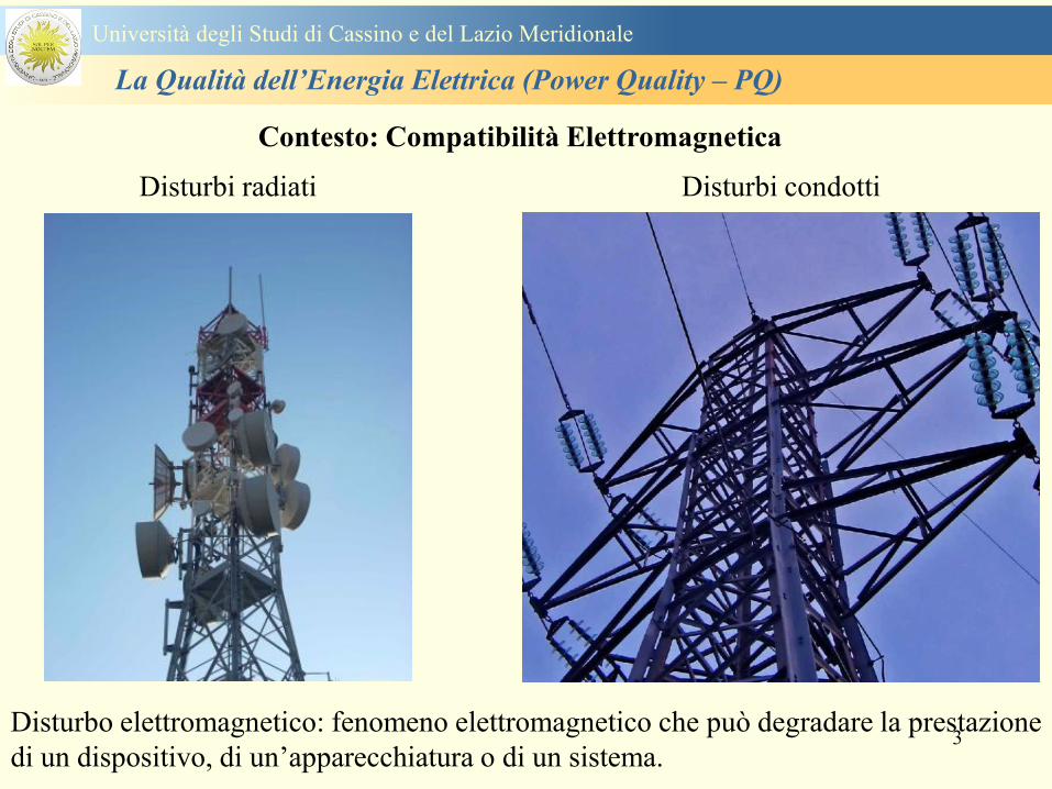
3
Contesto Compatibilitagrave Elettromagnetica
Disturbi radiati Disturbi condotti
Disturbo elettromagnetico fenomeno elettromagnetico che puograve degradare la prestazione
di un dispositivo di unrsquoapparecchiatura o di un sistema
Universitagrave degli Studi di Cassino e del Lazio Meridionale
La Qualitagrave dellrsquoEnergia Elettrica (Power Quality ndash PQ)
4
CIRCUITI NON LINEARI
Equivalent circuit of a non-linear load
Ih
Vh
Universitagrave degli Studi di Cassino e del Lazio Meridionale
La Qualitagrave dellrsquoEnergia Elettrica (Power Quality ndash PQ)
5
Power quality
problems
Turn off the mixer love
the monitorrsquos flickering
again
are
usually of
terrestrial
origin
Universitagrave degli Studi di Cassino e del Lazio Meridionale
La Qualitagrave dellrsquoEnergia Elettrica (Power Quality ndash PQ)
6
Universitagrave degli Studi di Cassino e del Lazio Meridionale
La Qualitagrave dellrsquoEnergia Elettrica (Power Quality ndash PQ)
Dobbiamo separare gli eventi di power quality dagli altri
problemi
bullSe avete delle apparecchiature sensibili
bullDisservizi inaspettati e intermittentihellip
bullQualrsquoegrave la causa dei disservizi o guasti
Software bug Cattive connessioni
Errori delloperatore Temperatura
Screpolature nei materiali Umiditagrave
Bolle nellacqua di raffreddamento
ecc ecc
ndashOppure egrave un disturbo power quality
7
Universitagrave degli Studi di Cassino Corso di Fondamenti di Misure
La Qualitagrave dellrsquoEnergia Elettrica (Power Quality ndash PQ)
Tensione costante e pari alla nominale
Frequenza costante e pari alla nominale
Tensioni e correnti sinusoidali
Continuitagrave del servizio
Le condizioni ideali
I ldquodisturbirdquo rappresentano lo scostamento
dei parametri elettrici dai valori ideali e la
non continuitagrave del servizio
La valutazione complessiva di questi
aspetti egrave denominata Power Quality
8
The good
old days bull
bull Ideal
three-phase
system
voltage
Three balanced
ohmic-inductive
single-phase loads
on the three phase
mains
-150A
-100A
-50A
0A
50A
100A
150A
0ms 5ms 10ms 15ms 20ms
t
i
i1 (L1)
i1 (L2)
i1 (L3)
-350V
-250V
-150V
-50V
50V
150V
250V
350V
0ms 5ms 10ms 15ms 20ms
t
u u1 (L1)
u1 (L2)
u1 (L3 )
Universitagrave degli Studi di Cassino e del Lazio Meridionale
La Qualitagrave dellrsquoEnergia Elettrica (Power Quality ndash PQ)
9
Distorsione armonica
Interruzioni del servizio
Abbassamenti di tensione e sovratensioni
Buchi di tensione
Transitori
Frequenza nominale della tensione fornita
Flicker - variazioni rapide della tensione
Squilibrio delle tensioni
Universitagrave degli Studi di Cassino e del Lazio Meridionale
La Qualitagrave dellrsquoEnergia Elettrica (Power Quality ndash PQ)
10
IEC 61000-2-22002 Electromagnetic compatibility (EMC) ndash Part 2-2 Environment ndash
Compatibility levels for low-frequency conducted disturbances and signalling in public
lowvoltage power supply systems
IEC 61000-2-4 Electromagnetic compatibility (EMC) ndash Part 2-4 Environment ndash
Compatibility levels in industrial plants for low-frequency conducted disturbances
IEC 61000-3-8 Electromagnetic compatibility (EMC) ndash Part 3 Limits ndash Section 8 Signalling
on low-voltage electrical installations ndash Emission levels frequency bands and electromagnetic
disturbance levels
IEC 61000-4-42004 Electromagnetic compatibility (EMC) ndash Part 4-4 Testing and
measurement techniques ndash Electrical fast transientburst immunity test
IEC 61000-4-72002 Electromagnetic compatibility (EMC) ndash Part 4-7 Testing and
measurement techniques ndash General guide on harmonics and interharmonics measurements
and instrumentation for power supply systems and equipment connected thereto
IEC 61000-4-302008 Electromagnetic compatibility (EMC) ndash Part 4-30 Testing and
measurement techniques ndash Power quality measurement methods
IEC 61000-4-15 Electromagnetic compatibility (EMC) ndash Part 4 Testing and measurement
techniques ndash Section 15 Flickermeter ndash Functional and design specifications
IEC 61180 (all parts) High-voltage test techniques for low voltage equipment
Normativa di riferimento
Universitagrave degli Studi di Cassino e del Lazio Meridionale
La Qualitagrave dellrsquoEnergia Elettrica (Power Quality ndash PQ)
11
IEC 61000 - 4 ndash 30 Norm
Seri 61000 Electromagnetic Compatibility
International Electrotechnical Commission
Part 4 Test and Measurement Tecniques
Section 30 PQ measurement methods
IEC 61000 - 4 ndash 7 Norm
Section 7 General guide on harmonics
and interharmonics measurements and
instrumentation for power supply
systems and equipment connected
thereto
Part 2 Environment ndashCompatibility levels
Seri 61000 Electromagnetic Compatibility
IEC International Electrotechnical Commission
Section xx details on the application sector
Part 3 Limits
Part 4 Test and Measurement Tecniques
Universitagrave degli Studi di Cassino e del Lazio Meridionale
La Qualitagrave dellrsquoEnergia Elettrica (Power Quality ndash PQ)
12
EN 501602010-07 Caratteristiche della tensione fornita dalle reti pubbliche di distribuzione
dellrsquoenergia elettrica
Descrive e specifica le caratteristiche principali della tensione ai terminali di
alimentazione di un utente della rete pubblica in bassa media e alta tensione in corrente
alternata in normali condizioni di esercizio Essa descrive i limiti o valori entro i quali le
caratteristiche della tensione possono essere attesi ai punti di alimentazione da reti elettriche
pubbliche europee e non descrive la situazione media sperimentata da un singolo utente di rete
Le caratteristiche della tensione fornite nella presente Norma non sono utilizzabili ai fini dei
limiti di EMC o di disturbi condotti nella rete pubblica Esse non sono utilizzabili ai fini di
prescrizioni nelle norme di prodotto o nelle norme per impianti
Normativa di riferimento
Universitagrave degli Studi di Cassino e del Lazio Meridionale
La Qualitagrave dellrsquoEnergia Elettrica (Power Quality ndash PQ)
13
Nel dettaglio la norma EN 50160 definisce i seguenti parametri
1 Frequenza nominale della tensione fornita
2 Ampiezza della tensione di alimentazione
3 Variazioni della tensione di alimentazione
4 Flicker - variazioni rapide della tensione
5 Buchi di tensione
6 Interruzioni della tensione di alimentazione
7 Squilibrio della tensione di alimentazione
8 Tensioni armoniche THD e fino al 25deg ordine
Universitagrave degli Studi di Cassino e del Lazio Meridionale
La Qualitagrave dellrsquoEnergia Elettrica (Power Quality ndash PQ)
14
Si specifica che qualora lrsquoazienda distributrice installi un registratore
della qualitagrave delle caratteristiche della tensione diverse dalle
interruzioni senza preavviso lunghe brevi e transitorie lo strumento
deve essere conforme alla norma tecnica EN 61000-4-30
Richiami nella delibera 042004
dellAUTORITA PER LENERGIA ELETTRICA E IL GAS
Il 30 gennaio 2004 con delibera 404 lrsquoautoritagrave dellrsquoenergia ha indicato tra i vari
argomenti trattati i criteri di misura delle qualitagrave della tensione
Nellrsquoarticolo 39 (pagina 29) viene indicato nel punto 391 e 2 che per la
registrazione di interruzioni senza preavviso lunghe brevi e transitorie occorre
utilizzare un registratore conforme alla CEI EN 50160 In questo caso lo strumento
registratore dice quando e per quanto si ha unrsquointerruzione del servizio ma a tutti gli
effetti NON EFFETTUA UNrsquoOSSERVAZIONE QUALITATIVA dei parametri
Universitagrave degli Studi di Cassino e del Lazio Meridionale
La Qualitagrave dellrsquoEnergia Elettrica (Power Quality ndash PQ)
15
Universitagrave degli Studi di Cassino e del Lazio Meridionale
La Qualitagrave dellrsquoEnergia Elettrica (Power Quality ndash PQ)
16
17
Universitagrave degli Studi di Cassino e del Lazio Meridionale
La Qualitagrave dellrsquoEnergia Elettrica (Power Quality ndash PQ)
CURVA DI TOLLERANZA AI DISTURBI
18
Caratteristiche dellrsquoalimentazione a bassa tensione
Universitagrave degli Studi di Cassino e del Lazio Meridionale
La Qualitagrave dellrsquoEnergia Elettrica (Power Quality ndash PQ)
19
Caratteristiche dellrsquoalimentazione a bassa tensione
Frequenza nominale
La frequenza nominale della tensione fornita deve essere di 50 Hz In condizioni normali
di esercizio il valore medio misurato nellrsquointervallo di 10 secondi deve essere
Per i sistemi con collegamento sincrono ad un sistema interconnesso
1 50 Hz plusmn 1 durante il 95 di un anno
2 50 Hz +4 - 6 durante il 100 di un anno
Per i sistemi senza collegamento sincrono ad un sistema interconnesso
1 50 Hz plusmn 2 durante il 95 di un anno
2 50 Hz plusmn 15 durante il 100 di un anno
Universitagrave degli Studi di Cassino e del Lazio Meridionale
La Qualitagrave dellrsquoEnergia Elettrica (Power Quality ndash PQ)
20
Caratteristiche dellrsquoalimentazione a bassa tensione
Universitagrave degli Studi di Cassino e del Lazio Meridionale
La Qualitagrave dellrsquoEnergia Elettrica (Power Quality ndash PQ)
21
Caratteristiche dellrsquoalimentazione a bassa tensione
Universitagrave degli Studi di Cassino e del Lazio Meridionale
La Qualitagrave dellrsquoEnergia Elettrica (Power Quality ndash PQ)
22
Variazioni della tensione di alimentazione (variazioni lente)
Le variazioni lente sono deviazioni ldquomedierdquo dal valore nominale dellrsquoampiezza della
tensione di consegna entro una fascia predefinita (per esempio del plusmn10) rispetto alla
tensione dichiarata
CAUSE variazione lenta dei carichi e dalla corrispondente azione di regolazione effettuata dai
variatori sotto carico dei trasformatori
Universitagrave degli Studi di Cassino e del Lazio Meridionale
La Qualitagrave dellrsquoEnergia Elettrica (Power Quality ndash PQ)
23
Variazioni della tensione di alimentazione (variazioni rapide)
Le variazioni rapide sono abbassamenti (o aumenti) bruschi di qualche percento della
tensione preesistente generalmente seguiti se abbassamenti da un ritorno (a rampa o di
altra forma) ad un valore intermedio tra quello preesistente e tra il minimo raggiunto
CAUSE commutazione dei carichi (partenza motori in particolare) funzionamento di carichi
con ciclo operativo particolarmente variabile e in qualche caso da manovre in rete (linee
trasformatori condensatori ecc)
Universitagrave degli Studi di Cassino e del Lazio Meridionale
La Qualitagrave dellrsquoEnergia Elettrica (Power Quality ndash PQ)
24
Flicker Il flicker egrave originato dalla fluttuazione della tensione Si definisce fluttuazione di tensione una
serie di variazioni rapide (uguali o diverse) della tensione
Fluttuazioni di tensione che presentano frequenze di modulazione del 50 Hz comprese tra 05 e
40 Hz danno origine al fenomeno del flicker (sfarfallio) ovvero della sensazione visiva
provocata dalle fluttuazioni dellrsquointensitagrave di illuminazione delle lampade
I suoi principali effetti sullrsquouomo possono essere mal di testa irritabilitagrave e fastidio agli occhi
Universitagrave degli Studi di Cassino e del Lazio Meridionale
La Qualitagrave dellrsquoEnergia Elettrica (Power Quality ndash PQ)
25
Universitagrave degli Studi di Cassino e del Lazio Meridionale
La Qualitagrave dellrsquoEnergia Elettrica (Power Quality ndash PQ)
26
La Qualitagrave dellrsquoEnergia Elettrica (Power Quality ndash PQ)
Universitagrave degli Studi di Cassino e del Lazio Meridionale
La Qualitagrave dellrsquoEnergia Elettrica (Power Quality ndash PQ)
27
Universitagrave degli Studi di Cassino e del Lazio Meridionale
La Qualitagrave dellrsquoEnergia Elettrica (Power Quality ndash PQ)
28
Universitagrave degli Studi di Cassino e del Lazio Meridionale
La Qualitagrave dellrsquoEnergia Elettrica (Power Quality ndash PQ)
29
Universitagrave degli Studi di Cassino e del Lazio Meridionale
La Qualitagrave dellrsquoEnergia Elettrica (Power Quality ndash PQ)
30
Universitagrave degli Studi di Cassino e del Lazio Meridionale
La Qualitagrave dellrsquoEnergia Elettrica (Power Quality ndash PQ)
31
Universitagrave degli Studi di Cassino e del Lazio Meridionale
La Qualitagrave dellrsquoEnergia Elettrica (Power Quality ndash PQ)
32
Buchi di tensione Riduzione temporanea della tensione in un punto della rete elettrica sotto una determinata
soglia Se durante un buco la tensione scende sotto una soglia di interruzione lrsquoevento egrave
considerato essere sia un buco che unrsquointerruzione
CAUSE I buchi di tensione sono generalmente dovuti a guasti che sopravvengono negli
impianti utilizzatori o nel sistema di distribuzione pubblico Possono dipendere anche variazioni
di carico lungo la linea
Universitagrave degli Studi di Cassino e del Lazio Meridionale
La Qualitagrave dellrsquoEnergia Elettrica (Power Quality ndash PQ)
33
Interruzioni della tensione di alimentazione Condizione in cui la tensione ad un terminale della rete egrave inferiore allrsquo1 della tensione
nominale per una durata fino a tre minuti (brevi) o maggiori di 3 minuti (lunghe)
Universitagrave degli Studi di Cassino e del Lazio Meridionale
La Qualitagrave dellrsquoEnergia Elettrica (Power Quality ndash PQ)
34
Sovratensioni temporanee alla frequenza di rete fra fasi e terra Le sovratensioni sono sopraelevazioni della tensione conseguenti a modificazioni dello
stato elettrico della rete elettrica
Universitagrave degli Studi di Cassino e del Lazio Meridionale
La Qualitagrave dellrsquoEnergia Elettrica (Power Quality ndash PQ)
35
Armoniche Le armoniche sono tensioni o correnti sinusoidali con frequenza pari ad un multiplo intero
(ordine) della frequenza fondamentale di funzionamento del sistema elettrico la cui
presenza determina una distorsione della forma drsquoonda della tensione di alimentazione
CAUSE In piccola parte dal sistema stesso (trasformatori etc) e per la maggior parte da
apparecchi utilizzatori carichi commutati elettronicamente raddrizzatori convertitori regolatori
in AC cicloconvertitori ecc carichi con caratteristiche non lineari apparecchiature a
saturazione magnetica lampade a scarica forni ad arco saldatrici ad arco trasformatori ecc
bull carichi inseriti e disinseriti da organi di manovra condensatori filtri e motori a induzione
Universitagrave degli Studi di Cassino e del Lazio Meridionale
La Qualitagrave dellrsquoEnergia Elettrica (Power Quality ndash PQ)
36
Armoniche di tensione e corrente ndash Problemi
Vi sono diversi ambiti causati dalle armoniche
bull problemi causati da armoniche di corrente
1048707 sovraccarico del neutro
1048707 aumento delle perdite nei trasformatori
1048707 interventi intempestivi degli interruttori automatici
1048707 aumento dellrsquoeffetto pelle
bull problemi causati da armoniche di tensione
1048707 deformazione della tensione
1048707 disturbi nella coppia dei motori ad induzione
1048707 rumore al passaggio per lo zero
bull problemi causati quando le armoniche di corrente raggiungono lrsquoalimentazione
Universitagrave degli Studi di Cassino e del Lazio Meridionale
La Qualitagrave dellrsquoEnergia Elettrica (Power Quality ndash PQ)
37
38
Universitagrave degli Studi di Cassino e del Lazio Meridionale
La Qualitagrave dellrsquoEnergia Elettrica (Power Quality ndash PQ)
39
Strumentazione ldquohand heldrdquo con display
Universitagrave degli Studi di Cassino e del Lazio Meridionale
La Qualitagrave dellrsquoEnergia Elettrica (Power Quality ndash PQ)
40
Strumentazione ldquohand heldrdquo con display
Universitagrave degli Studi di Cassino e del Lazio Meridionale
La Qualitagrave dellrsquoEnergia Elettrica (Power Quality ndash PQ)
41
Strumentazione da registrazione
Universitagrave degli Studi di Cassino e del Lazio Meridionale
La Qualitagrave dellrsquoEnergia Elettrica (Power Quality ndash PQ)
42
Schema di principio ndash 61000-4-30 copy IEC2008
The electrical quantity to be measured may be either directly accessible as is
generally the case in low-voltage systems or accessible via measurement
transducers
An instrument may include the whole measurement chain In this standard the
normative part does not consider the measurement transducers external to the
instrument and their associated uncertainty
Universitagrave degli Studi di Cassino e del Lazio Meridionale
La Qualitagrave dellrsquoEnergia Elettrica (Power Quality ndash PQ)
43
Universitagrave degli Studi di Cassino Corso di Fondamenti di Misure
La Qualitagrave dellrsquoEnergia Elettrica (Power Quality ndash PQ)
Classi dei metodi di misura - 61000-4-30 copy IEC2008
For each class measurement methods and appropriate performance requirements
are included
Sono definite tre classi A S e B
Class A
This class is used where precise measurements are necessary for example for contractual
applications that may require resolving disputes verifying compliance with standards etc
Any measurements of a parameter carried out with two different instruments complying with
the requirements of Class A when measuring the same signals will produce matching results
within the specified uncertainty for that parameter
Class S
This class is used for statistical applications such as surveys or power quality assessment
possibly with a limited subset of parameters Although it uses equivalent intervals of
measurement as class A the class S processing requirements are lower
Class B
This class is defined in order to avoid making many existing instruments designs obsolete
NOTE Class B methods are not recommended for new designs Readers are advised that Class B may be removed in a
future Edition of this standard
44
Classi dei metodi di misura - 61000-4-30 copy IEC2008
Measurement aggregation over time intervals
CLASS A
The basic measurement time interval for parameter magnitudes (supply voltage harmonics
interharmonics and unbalance) shall be a 10-cycle time interval for a 50 Hz power system
or 12-cycle time interval for a 60 Hz power system
The 1012-cycle measurement shall be re-synchronized at every RTC 10 min tick
The 1012-cycle values are then aggregated over 3 additional intervals
ndash 150180-cycle interval (150 cycles for 50 Hz nominal or 180 cycles for 60 Hz nominal)
ndash 10 min interval
ndash 2 h interval
CLASS S
Same time intervals as Class A
CLASS B
The manufacturer shall specify the number and duration of aggregation time intervals
Universitagrave degli Studi di Cassino e del Lazio Meridionale
La Qualitagrave dellrsquoEnergia Elettrica (Power Quality ndash PQ)
45
Universitagrave degli Studi di Cassino e del Lazio Meridionale
La Qualitagrave dellrsquoEnergia Elettrica (Power Quality ndash PQ)
46
Universitagrave degli Studi di Cassino e del Lazio Meridionale
La Qualitagrave dellrsquoEnergia Elettrica (Power Quality ndash PQ)
Class A
The 10-min aggregated value shall be tagged with the absolute time (for
example 01H1000) The time tag is the time at the conclusion of the 10-min
aggregation
The data for the 10-min time interval shall be aggregated from 1012-cycle time
intervals
Each 10-minute interval shall begin on a UTC 10-min tick The 10-min tick is
also used to re-synchronize the 1012-cycle intervals and the 150180-cycle
intervals
The final 1012-cycle interval(s) in a 10-min aggregation period will typically
overlap in time with the UTC 10-min clock tick Any overlapping 1012-cycle
interval (Overlap 1 in Figure 2) is included in the aggregation of the previous
10-min interval
47
Universitagrave degli Studi di Cassino e del Lazio Meridionale
La Qualitagrave dellrsquoEnergia Elettrica (Power Quality ndash PQ)
48
Universitagrave degli Studi di Cassino e del Lazio Meridionale
La Qualitagrave dellrsquoEnergia Elettrica (Power Quality ndash PQ)
49
Classi dei metodi di misura - 61000-4-30 copy IEC2008
Real time clock (RTC) uncertainty
Sono definite le specifiche per le 3 classi
Flagging concept
During a dip swell or interruption the measurement algorithm for other
parameters (for example frequency measurement) might produce an unreliable
value The flagging concept therefore avoids counting a single event more than
once in different parameters (for example counting a single dip as both a dip and a
frequency variation) and indicates that an aggregated value might be unreliable
Universitagrave degli Studi di Cassino e del Lazio Meridionale
La Qualitagrave dellrsquoEnergia Elettrica (Power Quality ndash PQ)
50
Classi dei metodi di misura - 61000-4-30 copy IEC2008
Power quality parameters - INDICES
Per ogni parametro viene suggerito il metodo di misura per le tre classi e
(soprattutto) le caratteristiche di precisione Per alcuni parametri rimanda a
specifiche norme (ad esempio Flicker e Armonicheinterarmoniche)
Esempio - Power frequency Class A
The frequency reading shall be obtained every 10 s As power frequency may not be exactly 50 Hz or 60
Hz within the 10 s time clock interval the number of cycles may not be an integer number The
fundamental frequency output is the ratio of the number of integral cycles counted during the 10 s time
clock interval divided by the cumulative duration of the integer cycles Before each assessment
harmonics and interharmonics shall be attenuated to minimize the effects of multiple zero crossings
The measurement time intervals shall be non-overlapping Individual cycles that overlap the 10 s time
clock are discarded Each 10 s interval shall begin on an absolute 10 s time clock with uncertainty as
defined in 46
Other techniques that provide equivalent results such as convolution are acceptable
Class S Same as class A
Class B The manufacturer shall specify the process used for frequency measurement
Universitagrave degli Studi di Cassino e del Lazio Meridionale
La Qualitagrave dellrsquoEnergia Elettrica (Power Quality ndash PQ)
51
Classi dei metodi di misura - 61000-4-30 copy IEC2008
Power quality parameters - INDICES
Per ogni parametro viene suggerito il metodo di misura per le tre classi e
(soprattutto) le caratteristiche di precisione Per alcuni parametri rimanda a
specifiche norme (ad esempio Flicker e Armonicheinterarmoniche)
Esempio - Power frequency
Measurement uncertainty and measuring range
ndash Class A
Under the conditions described in 61 the measurement uncertainty shall not exceed
plusmn10 mHz over the measuring ranges 425 Hz ~ 575 Hz 51 Hz ~ 69 Hz
ndash Class S
Under the conditions described in 61 the measurement uncertainty shall not exceed
plusmn50 mHz over the measuring ranges 425 Hz ~ 575 Hz 51 Hz ~ 69 Hz
ndash Class B
The manufacturer shall specify the uncertainty over the measuring ranges 425 Hz ~
575 Hz 51 Hz ~ 69 Hz
Universitagrave degli Studi di Cassino e del Lazio Meridionale
La Qualitagrave dellrsquoEnergia Elettrica (Power Quality ndash PQ)
52
Magnitude of the supply voltage
Measurement method
ndash Class A
The measurement shall be the rms value of the voltage magnitude over
a 10-cycle time interval for 50 Hz power system or 12-cycle time
interval for 60 Hz power system Every 1012-cycle interval shall be
contiguous and not overlapping with adjacent 1012-cycle intervals
except as shown as Overlap 1 in Figure 2
NOTE 1 This specific measurement method is used for quasi-stationary signals and is
not used for the detection and measurement of disturbances dips swells voltage
interruptions and transients
NOTE 2 The rms value includes by definition harmonics interharmonics mains
signalling etc
- Class S same as Class A
Universitagrave degli Studi di Cassino e del Lazio Meridionale
La Qualitagrave dellrsquoEnergia Elettrica (Power Quality ndash PQ)
53
Magnitude of the supply voltage
Measurement uncertainty and measuring range
ndash Class A
Under the conditions described in Clause 6 the measurement uncertainty
shall not exceed plusmn01 of Udin over the range of 10 ~ 150 of Udin
ndash Class S
Under the conditions described in Clause 6 the measurement uncertainty
shall not exceed plusmn05 of Udin over the range of 20 ~ 120 of Udin
Universitagrave degli Studi di Cassino e del Lazio Meridionale
La Qualitagrave dellrsquoEnergia Elettrica (Power Quality ndash PQ)
54
Supply voltage dips and swells
Measurement method
ndash Class A
The basic measurement Urms of a voltage dip and swell shall be the
Urms(frac12) on each measurement channel (see Clause 322)
The cycle duration for Urms(frac12) depends on the frequency The
frequency might be determined by the last non-flagged power frequency
measurement (see Clause 47 and Clause 51) or by any other method
that yields the uncertainty requirements of Clause 6
NOTE 1 The Urms(frac12) value includes by definition harmonics interharmonics mains
signalling voltage etc
NOTE 2 It is important to avoid loss of data when dips and swells occur in a rapid
sequence (for example three events in one second with up to one minute between
sequences may occur when a recloser operates into a sustained fault) If during a rapid
burst the dipswell event characteristics cannot be recorded then a count of events may
be useful
Universitagrave degli Studi di Cassino e del Lazio Meridionale
La Qualitagrave dellrsquoEnergia Elettrica (Power Quality ndash PQ)
55
Supply voltage dips and swells
Detection and evaluation of a voltage dip
Voltage dip detection
The dip threshold is a percentage of either Udin or the sliding voltage
reference Usr (see 525 544) The user shall declare the reference
voltage in use
NOTE ndash On single-phase systems a voltage dip begins when the Urms voltage falls
below the dip threshold and ends when the Urms voltage is equal to or above the dip
threshold plus the hysteresis voltage
ndash On polyphase systems a dip begins when the Urms voltage of one or more channels is
below the dip threshold and ends when the Urms voltage on all measured channels is
equal to or above the dip threshold plus the hysteresis voltage
The dip threshold and the hysteresis voltage are both set by the user according to the
use
Universitagrave degli Studi di Cassino e del Lazio Meridionale
La Qualitagrave dellrsquoEnergia Elettrica (Power Quality ndash PQ)
56
Calculation of a sliding reference voltage
The sliding reference voltage implementation is optional not mandatory
If a sliding reference is chosen for voltage dip or swell detection this
shall be calculated using a first-order filter with a 1-min time constant
This filter is given by
Usr(n) = 09967 times Usr(nndash1) + 00033 times U(1012)rms
where
Usr(n) is the present value of the sliding reference voltage
Usr(nndash1) is the previous value of the sliding reference voltage and
U(1012)rms is the most recent 1012-cycle rms value
When the measurement is started the initial value of the sliding reference voltage is set
to the declared input voltage The sliding reference voltage is updated every 1012-
cycles If a 1012-cycle value is flagged the sliding reference voltage is not updated
and the previous value is used
Universitagrave degli Studi di Cassino e del Lazio Meridionale
La Qualitagrave dellrsquoEnergia Elettrica (Power Quality ndash PQ)
57
Supply voltage dips and swells
Voltage dip evaluation
A voltage dip is characterized by a pair of data either residual voltage
(Ures) or depth and duration
ndash the residual voltage of a voltage dip is the lowest Urms(frac12) value
measured on any channel during the dip
ndash the depth is the difference between the reference voltage (either Udin
or Usr) and the residual voltage It is generally expressed in percentage
of the reference voltage
NOTE 1 During the dip it may be useful to also record the lowest Urms(frac12) on each
channel in addition to the residual voltage of the dip The duration spent below the dip
threshold on each channel may also be useful
Universitagrave degli Studi di Cassino e del Lazio Meridionale
La Qualitagrave dellrsquoEnergia Elettrica (Power Quality ndash PQ)
58
Supply voltage dips and swells
Voltage dip evaluation
NOTE 2 If voltage waveforms are recorded before during and after a
dip useful information about phase angle changes may be available in
the recorded data
The start time of a dip shall be time stamped with the time of the start of
the Urms of the channel that initiated the event and the end time of the
dip shall be the time stamped with the time of the end of the Urms that
ended the event as defined by the threshold plus the hysteresis
The duration of a voltage dip is the time difference between the start
time and the end time of the voltage dip
Universitagrave degli Studi di Cassino e del Lazio Meridionale
La Qualitagrave dellrsquoEnergia Elettrica (Power Quality ndash PQ)
59
Supply voltage dips and swells
Residual voltage and swell voltage magnitude measurement
uncertainty
ndash Class A
The measurement uncertainty shall not exceed plusmn02 of Udin
ndash Class S
The measurement uncertainty shall not exceed plusmn10 of Udin
Universitagrave degli Studi di Cassino e del Lazio Meridionale
La Qualitagrave dellrsquoEnergia Elettrica (Power Quality ndash PQ)
60
Schema di principio ndash 61000-4-7 copy IEC2002
Universitagrave degli Studi di Cassino e del Lazio Meridionale
La Qualitagrave dellrsquoEnergia Elettrica (Power Quality ndash PQ)
61
Universitagrave degli Studi di Cassino e del Lazio Meridionale
La Qualitagrave dellrsquoEnergia Elettrica (Power Quality ndash PQ)
62
Universitagrave degli Studi di Cassino e del Lazio Meridionale
La Qualitagrave dellrsquoEnergia Elettrica (Power Quality ndash PQ)
63
Inter-Armoniche Le inter-armoniche sono tensioni o correnti sinusoidali con frequenza diversa da un
multiplo intero della fondamentale la cui presenza determina una distorsione
(modulazione) della forma donda della tensione di alimentazione
CAUSE dai carichi che assorbono correnti inter-armoniche
- carichi commutati elettronicamente convertitori cascata subsincrona cicloconvertitori regolatori con
controllo a pacchetti di cicli ecc
- carichi con caratteristiche non lineari eo non stazionarie forni ad arco saldatrici ad arco ecc
Universitagrave degli Studi di Cassino e del Lazio Meridionale
La Qualitagrave dellrsquoEnergia Elettrica (Power Quality ndash PQ)
64
Universitagrave degli Studi di Cassino e del Lazio Meridionale
La Qualitagrave dellrsquoEnergia Elettrica (Power Quality ndash PQ)
Un porsquo di esempi e
consigli praticihellip
65
0V
50V
100V
150V
200V
250V
300V
350V
0ms 5ms 10ms 15ms 20ms
t
u
0A
1A
2A
3A
i
0V
50V
100V
150V
200V
250V
300V
350V
0ms 5ms 10ms 15ms 20ms
t
u
0A
1A
2A
3A
i
0V
50V
100V
150V
200V
250V
300V
350V
0ms 5ms 10ms 15ms 20ms
t
u
0A
1A
2A
3A
i
gleichgerichtete
Netzspannung
Kondensator-
spannung
gleichgerichteter
Netzstrom
The situation
today
bull Computed current and voltage profiles when a
230 V 58 W fluorescent lamp with an old-style
electronic ballast is driven on the phase wire of
a typical power distribution system
System voltage 230 V
System frequency 50 Hz
Source resistance 500 mW
Longitudinal induction 904 microH
System impedance 575 mW
Mean dc current 180 mA
Smoothing capacitance220 microF
66
And what about electronic ballasts that are rated over 25W
Introduce electronic power factor correction (PFC)
0V
20V
40V
60V
80V
100V
120V
140V
160V
180V
200V
220V
0deg 15deg 30deg 45deg
u
00A
03A
06A
09A
12A
i
67
Though todayrsquos ballasts are better if
rated gt25 W bull Only
the
small
ones
continu
e to
pollute
just like
PCs
TV sets
do
68
This leads to a number of
previously unknown effects bull 1 Deformed voltage curves
bull 2 Huge inrush current peaks
bull 3 Instrument dependent measured parameters
bull 4 Increased loading of phase conductors
bull 5 Loading and overloading of the neutral conductor
bull 6 Overheating and start-up problems of induction motors
bull 7 Additional stray losses in transformers
bull 8 Repercussions of generators upon the mains
bull 9 Influence of capacitors repercussions upon the mains
and four additional complications in TN-C systems
10 Stray currents in equipotential bonding system magnetic fields
11 Contamination of data streams by stray currents
12 Stray currents in the earthing system corrosion damage
13 Lightning currents in devices and equipment
69
1 Deformed voltage curves
bull in theory
-350V
-300V
-250V
-200V
-150V
-100V
-50V
0V
50V
100V
150V
200V
250V
300V
350V
0 5 10 15 20
t ms
u
System voltage profile when driving
a single-phase load comprising
twenty 58 W energy-saver lamps in
parallel on a typical 230 V power
system
70
and in practice
bull An actual
current profile
bull
bull and
bull a voltage profile
bull
bull recorded in a large storage
dispatch and administrative
building
71
at home or in industrial environments
bull
bull Television 40
W
bull 200 Vdiv 2
Adiv
bull 5 msdiv
Harmonic
spectrum
Frequency
converter
50 Adiv
Phase currents
I1=I2=I3=160 A
IN=295 A
5 msdiv
72
Every periodic waveform can be written
as the infinite sum of sinusoidal waves
-175
-150
-125
-100
-75
-50
-25
0
25
50
75
100
125
150
175
0 5 10 15 20
t ms
i
mA
itot
i1
Synthesis of a triangular current profile 100mA
Content fundamental I = 99 mA Isup2 = 9855 mAsup2
Sum of squares Isup2 = 9855 mAsup2
Root of sum = RMS value I = 99 mA
-175
-150
-125
-100
-75
-50
-25
0
25
50
75
100
125
150
175
0 5 10 15 20
t ms
i
mA
itot
i1
i3
Synthesis of a triangular current profile 100mA
Content fundamental I = 99 mA Isup2 = 9855 mAsup2
Cont 3 rd harmonic I = -11 mA Isup2 = 122 mAsup2
Sum of squares Isup2 = 9977 mAsup2
Root of sum = RMS value I = 100 mA
-175
-150
-125
-100
-75
-50
-25
0
25
50
75
100
125
150
175
0 5 10 15 20
t ms
i
mA
itot
i1
i3
i5
Synthesis of a triangular current profile 100mA
Content fundamental I = 99 mA Isup2 = 9855 mAsup2
Cont 3 rd harmonic I = -11 mA Isup2 = 122 mAsup2
Cont 5 th harmonic I = 4 mA Isup2 = 16 mAsup2
Sum of squares Isup2 = 9993 mAsup2
Root of sum = RMS value I = 100 mA
-175
-150
-125
-100
-75
-50
-25
0
25
50
75
100
125
150
175
0 5 10 15 20
t ms
i
mA
itot
i1
i3
i5
i7
Synthesis of a triangular current profile 100mA
Content fundamental I = 99 mA Isup2 = 9855 mAsup2
Cont 3 rd harmonic I = -11 mA Isup2 = 122 mAsup2
Cont 5 th harmonic I = 4 mA Isup2 = 16 mAsup2
Cont 7 th harmonic I = -2 mA Isup2 = 4 mAsup2
Sum of squares Isup2 = 9997 mAsup2
Root of sum = RMS value I = 100 mA
-175
-150
-125
-100
-75
-50
-25
0
25
50
75
100
125
150
175
0 5 10 15 20
t ms
i
mA
itot i1
i3 i5
i7 i9
Synthesis of a triangular current profile 100mA
Content fundamental I = 99 mA Isup2 = 9855 mAsup2
Cont 3 rd harmonic I = -11 mA Isup2 = 122 mAsup2
Cont 5 th harmonic I = 4 mA Isup2 = 16 mAsup2
Cont 7 th harmonic I = -2 mA Isup2 = 4 mAsup2
Cont 9 th harmonic I = 1 mA Isup2 = 2 mAsup2
Sum of squares Isup2 = 9998 mAsup2
Root of sum = RMS value I = 100 mA
-175
-150
-125
-100
-75
-50
-25
0
25
50
75
100
125
150
175
0 5 10 15 20
t ms
i
mA
itot i1
i3 i5
i7 i9
i11
Synthesis of a triangular current profile 100mA
Content fundamental I = 99 mA Isup2 = 9855 mAsup2
Cont 3 rd harmonic I = -11 mA Isup2 = 122 mAsup2
Cont 5 th harmonic I = 4 mA Isup2 = 16 mAsup2
Cont 7 th harmonic I = -2 mA Isup2 = 4 mAsup2
Cont 9 th harmonic I = 1 mA Isup2 = 2 mAsup2
Cont 11 th harmonic I = -1 mA Isup2 = 1 mAsup2
Sum of squares Isup2 = 9999 mAsup2
Root of sum = RMS value I = 100 mA
-175
-150
-125
-100
-75
-50
-25
0
25
50
75
100
125
150
175
0 5 10 15 20
t ms
i
mA
itot i1
i3 i5
i7 i9
i11 i13
Synthesis of a triangular current profile 100mA
Content fundamental I = 99 mA Isup2 = 9855 mAsup2
Cont 3 rd harmonic I = -11 mA Isup2 = 122 mAsup2
Cont 5 th harmonic I = 4 mA Isup2 = 16 mAsup2
Cont 7 th harmonic I = -2 mA Isup2 = 4 mAsup2
Cont 9 th harmonic I = 1 mA Isup2 = 2 mAsup2
Cont 11 th harmonic I = -1 mA Isup2 = 1 mAsup2
Cont 13 th harmonic I = 1 mA Isup2 = 0 mAsup2
Sum of squares Isup2 = 9999 mAsup2
Root of sum = RMS value I = 100 mA
-175
-150
-125
-100
-75
-50
-25
0
25
50
75
100
125
150
175
0 5 10 15 20
t ms
i
mA
itot i1
i3 i5
i7 i9
i11 i13
i15
Synthesis of a triangular current profile 100mA
Content fundamental I = 99 mA Isup2 = 9855 mAsup2
Cont 3 rd harmonic I = -11 mA Isup2 = 122 mAsup2
Cont 5 th harmonic I = 4 mA Isup2 = 16 mAsup2
Cont 7 th harmonic I = -2 mA Isup2 = 4 mAsup2
Cont 9 th harmonic I = 1 mA Isup2 = 2 mAsup2
Cont 11 th harmonic I = -1 mA Isup2 = 1 mAsup2
Cont 13 th harmonic I = 1 mA Isup2 = 0 mAsup2
Cont 15 th harmonic I = 0 mA Isup2 = 0 mAsup2
Sum of squares Isup2 = 10000 mAsup2
Root of sum = RMS value I = 100 mA
-175
-150
-125
-100
-75
-50
-25
0
25
50
75
100
125
150
175
0 5 10 15 20
t ms
i
mA
itot i1
i3 i5
i7 i9
i11 i13
i15 i17
Synthesis of a triangular current profile 100mA
Content fundamental I = 99 mA Isup2 = 9855 mAsup2
Cont 3 rd harmonic I = -11 mA Isup2 = 122 mAsup2
Cont 5 th harmonic I = 4 mA Isup2 = 16 mAsup2
Cont 7 th harmonic I = -2 mA Isup2 = 4 mAsup2
Cont 9 th harmonic I = 1 mA Isup2 = 2 mAsup2
Cont 11 th harmonic I = -1 mA Isup2 = 1 mAsup2
Cont 13 th harmonic I = 1 mA Isup2 = 0 mAsup2
Cont 15 th harmonic I = 0 mA Isup2 = 0 mAsup2
Cont 17 th harmonic I = 0 mA Isup2 = 0 mAsup2
Sum of squares Isup2 = 10000 mAsup2
Root of sum = RMS value I = 100 mA
73
whose frequencies called harmonics are
integer multiples of the fundamental frequency
-175
-150
-125
-100
-75
-50
-25
0
25
50
75
100
125
150
175
0 5 10 15 20
t ms
i
mA
itot
i1
Synthesis of a rectangular current profile 100mA
Content fundamental I = 90 mA Isup2 = 8106 mAsup2
Sum of squares Isup2 = 8106 mAsup2
Root of sum = RMS value I = 90 mA
-175
-150
-125
-100
-75
-50
-25
0
25
50
75
100
125
150
175
0 5 10 15 20
t ms
i
mA
itot
i1
i3
Synthesis of a rectangular current profile 100mA
Content fundamental I = 90 mA Isup2 = 8106 mAsup2
Cont 3 rd harmonic I = 30 mA Isup2 = 901 mAsup2
Sum of squares Isup2 = 9006 mAsup2
Root of sum = RMS value I = 95 mA
-175
-150
-125
-100
-75
-50
-25
0
25
50
75
100
125
150
175
0 5 10 15 20
t ms
i
mA
itot
i1
i3
i5
Synthesis of a rectangular current profile 100mA
Content fundamental I = 90 mA Isup2 = 8106 mAsup2
Cont 3 rd harmonic I = 30 mA Isup2 = 901 mAsup2
Cont 5 th harmonic I = 18 mA Isup2 = 324 mAsup2
Sum of squares Isup2 = 9331 mAsup2
Root of sum = RMS value I = 97 mA
-175
-150
-125
-100
-75
-50
-25
0
25
50
75
100
125
150
175
0 5 10 15 20
t ms
i
mA
itot
i1
i3
i5
i7
Synthesis of a rectangular current profile 100mA
Content fundamental I = 90 mA Isup2 = 8106 mAsup2
Cont 3 rd harmonic I = 30 mA Isup2 = 901 mAsup2
Cont 5 th harmonic I = 18 mA Isup2 = 324 mAsup2
Cont 7 th harmonic I = 13 mA Isup2 = 165 mAsup2
Sum of squares Isup2 = 9496 mAsup2
Root of sum = RMS value I = 97 mA
-175
-150
-125
-100
-75
-50
-25
0
25
50
75
100
125
150
175
0 5 10 15 20
t ms
i
mA
itot i1
i3 i5
i7 i9
Synthesis of a rectangular current profile 100mA
Content fundamental I = 90 mA Isup2 = 8106 mAsup2
Cont 3 rd harmonic I = 30 mA Isup2 = 901 mAsup2
Cont 5 th harmonic I = 18 mA Isup2 = 324 mAsup2
Cont 7 th harmonic I = 13 mA Isup2 = 165 mAsup2
Cont 9 th harmonic I = 10 mA Isup2 = 100 mAsup2
Sum of squares Isup2 = 9596 mAsup2
Root of sum = RMS value I = 98 mA
-175
-150
-125
-100
-75
-50
-25
0
25
50
75
100
125
150
175
0 5 10 15 20
t ms
i
mA
itot i1
i3 i5
i7 i9
i11
Synthesis of a rectangular current profile 100mA
Content fundamental I = 90 mA Isup2 = 8106 mAsup2
Cont 3 rd harmonic I = 30 mA Isup2 = 901 mAsup2
Cont 5 th harmonic I = 18 mA Isup2 = 324 mAsup2
Cont 7 th harmonic I = 13 mA Isup2 = 165 mAsup2
Cont 9 th harmonic I = 10 mA Isup2 = 100 mAsup2
Cont 11 th harmonic I = 8 mA Isup2 = 67 mAsup2
Sum of squares Isup2 = 9663 mAsup2
Root of sum = RMS value I = 98 mA
-175
-150
-125
-100
-75
-50
-25
0
25
50
75
100
125
150
175
0 5 10 15 20
t ms
i
mA
itot i1
i3 i5
i7 i9
i11 i13
Synthesis of a rectangular current profile 100mA
Content fundamental I = 90 mA Isup2 = 8106 mAsup2
Cont 3 rd harmonic I = 30 mA Isup2 = 901 mAsup2
Cont 5 th harmonic I = 18 mA Isup2 = 324 mAsup2
Cont 7 th harmonic I = 13 mA Isup2 = 165 mAsup2
Cont 9 th harmonic I = 10 mA Isup2 = 100 mAsup2
Cont 11 th harmonic I = 8 mA Isup2 = 67 mAsup2
Cont 13 th harmonic I = 7 mA Isup2 = 48 mAsup2
Sum of squares Isup2 = 9711 mAsup2
Root of sum = RMS value I = 99 mA
-175
-150
-125
-100
-75
-50
-25
0
25
50
75
100
125
150
175
0 5 10 15 20
t ms
i
mA
itot i1
i3 i5
i7 i9
i11 i13
i15
Synthesis of a rectangular current profile 100mA
Content fundamental I = 90 mA Isup2 = 8106 mAsup2
Cont 3 rd harmonic I = 30 mA Isup2 = 901 mAsup2
Cont 5 th harmonic I = 18 mA Isup2 = 324 mAsup2
Cont 7 th harmonic I = 13 mA Isup2 = 165 mAsup2
Cont 9 th harmonic I = 10 mA Isup2 = 100 mAsup2
Cont 11 th harmonic I = 8 mA Isup2 = 67 mAsup2
Cont 13 th harmonic I = 7 mA Isup2 = 48 mAsup2
Cont 15 th harmonic I = 6 mA Isup2 = 36 mAsup2
Sum of squares Isup2 = 9747 mAsup2
Root of sum = RMS value I = 99 mA
-175
-150
-125
-100
-75
-50
-25
0
25
50
75
100
125
150
175
0 5 10 15 20
t ms
i
mA
itot i1
i3 i5
i7 i9
i11 i13
i15 i17
Synthesis of a rectangular current profile 100mA
Content fundamental I = 90 mA Isup2 = 8106 mAsup2
Cont 3 rd harmonic I = 30 mA Isup2 = 901 mAsup2
Cont 5 th harmonic I = 18 mA Isup2 = 324 mAsup2
Cont 7 th harmonic I = 13 mA Isup2 = 165 mAsup2
Cont 9 th harmonic I = 10 mA Isup2 = 100 mAsup2
Cont 11 th harmonic I = 8 mA Isup2 = 67 mAsup2
Cont 13 th harmonic I = 7 mA Isup2 = 48 mAsup2
Cont 15 th harmonic I = 6 mA Isup2 = 36 mAsup2
Cont 17 th harmonic I = 5 mA Isup2 = 28 mAsup2
Sum of squares Isup2 = 9775 mAsup2
Root of sum = RMS value I = 99 mA
74
Even far better simulations are
available free of charge at
bull wwwpowerstandardscomMcEachern
75
-4A
-3A
-2A
-1A
0A
1A
2A
3A
4A
0ms 5ms 10ms 15ms 20ms
t
i
-4A
-3A
-2A
-1A
0A
1A
2A
3A
4A
0ms 5ms 10ms 15ms 20ms
t
i
Applying the Fourier
analysis to a real PC
current does not work
directly
bull
bull but it can be
modelled by a similar
triangular curve in
which not all of the
higher harmonics
have been included
Triangular current profile of
the same amplitude and a
pulse duty cycle of 17
Input current of a PC
with monitor
76
Analysis of the model triangular waveform
-400
-350
-300
-250
-200
-150
-100
-50
0
50
100
150
200
250
300
350
400
0 5 10 15 20
t ms
iI
itot(t) L1 [A] i1(t) L1 [A]
i3(t) L1 [A] i5(t) L1 [A]
i7(t) L1 [A] i9(t) L1 [A]
i11(t) L1 [A] i13(t) L1 [A]
i15(t) L1 [A] i17(t) L1 [A]
77
M3
Harmonics
Energy
(active
power)
L1
L2
L3
N
PE
Important
bull Harmonics are created within the loads
themselves and can flow ldquoupstreamrdquo to
contaminate the power system
78
-6A
-5A
-4A
-3A
-2A
-1A
0A
1A
2A
3A
4A
5A
6A
0ms 5ms 10ms 15ms 20ms
t
i
Squared values
Without
Fundamental 502 mA 251986 mAsup2 the fundamental
3rd harmonic -479 mA 229000 mAsup2 229000 mAsup2
5th harmonic 434 mA 188595 mAsup2 188595 mAsup2
7th harmonic -374 mA 139903 mAsup2 139903 mAsup2
9th harmonic 304 mA 92527 mAsup2 92527 mAsup2
11th harmonic -232 mA 53671 mAsup2 53671 mAsup2
13th harmonic 163 mA 26600 mAsup2 26600 mAsup2
15th harmonic -104 mA 10780 mAsup2 10780 mAsup2
17th harmonic 57 mA 3299 mAsup2 3299 mAsup2
Sum of the squares 996362 mAsup2 744377 mAsup2
Root thereof 998 mAeff THD = 863 mA
What actually is THD Example shown here triangular current
profile with an rms current of 1000 mA
and a pulse duty cycle of 17
THDr (root mean square) = 863mA1000mA = 86
THDf (fundamental) = 863mA502mA = 172
79
Effect on phase-to-neutral
and phase-to-phase voltages
bull Recorded
on June
30 2002
230 p
m
bull What
was the
matter
then
bull The
soccer
final
Germany
vs
Brazil
80
The triple-N harmonics drive
a circulating current in the
delta winding of a distribution
transformer
bull but the
bull voltage harmonics
propagate into the next
low-voltage power
distribution system
81 0V
50V
100V
150V
200V
250V
300V
350V
400V
450V
500V
550V
0 10 20 30 40 50
t ms
u
0A
10A
20A
30A
40A
50A
60A
70A
80A
90A
100A
110A
120A
130A
140A
150A
i
Switching on just as supply voltage passes through zero
0V
50V
100V
150V
200V
250V
300V
350V
400V
450V
500V
550V
0 10 20 30 40 50
t ms
u
0A
10A
20A
30A
40A
50A
60A
70A
80A
90A
100A
110A
120A
130A
140A
150A
i
Switching on just as supply voltage is at its peak
2 Huge inrush current peaks
ndash in theory
82
and in practice
bull Inrush current of a
compact energy-
saver lamp and its
effect on the system
voltage (recorded at
the Technical
University of
Budapest)
bull
83
enables us to infer what
happens when run by a
normal three-phase supply
The same fluorescent lamp
with a magnetic ballast
bull The behaviour measured
when connected to
a dc supply
bull
Behaviour of a 58 W fluorescent lamp connected to a dc
supply
0
20
40
60
80
100
120
140
160
180
200
0 200 400 600 800 1000 1200
i mA
u
V
Measurement
Behaviour of a 58 W fluorescent lamp connected to a dc
supply
0
20
40
60
80
100
120
140
160
180
200
0 200 400 600 800 1000 1200
i mA
u
V
MeasurementCalculation
-350
-300
-250
-200
-150
-100
-50
0
50
100
150
200
250
300
350
0 5 10 15 20
t ms
u
V
-10
-08
-06
-04
-02
00
02
04
06
08
10
i
A
Systems voltage
Current
-350
-300
-250
-200
-150
-100
-50
0
50
100
150
200
250
300
350
0 5 10 15 20
t ms
u
V
-10
-08
-06
-04
-02
00
02
04
06
08
10
i
A
Systems voltage
Lamp voltage
Current
84
Warning ldquoCompensationrdquo is not
always what you think it is
bull Distinguish
between
bull Reactive
power
compensatio
n
aka power
factor
correction
Remedial
measure
Parallel (or
sometimes series)
compensation
using capacitors
Filter circuits
tuned to the
individual harmonic
frequencies
Harmonic
compensation
85
5 (Over)loading the neutral conductor
bull Magnetic ballast Old-style electronic ballast
-25A
-20A
-15A
-10A
-05A
00A
05A
10A
15A
20A
25A
0 5 10 15 20
t ms i
i(t) N
-25A
-20A
-15A
-10A
-05A
00A
05A
10A
15A
20A
25A
0 5 10 15 20
t ms
i
i(t) N
-25A
-20A
-15A
-10A
-05A
00A
05A
10A
15A
20A
25A
0 5 10 15 20
t ms
i
i(t) L1 i(t) L2 i(t) L3
-25A
-20A
-15A
-10A
-05A
00A
05A
10A
15A
20A
25A
0 5 10 15 20
t ms
i
i(t) L1
i(t) L2
i(t) L3
86
Adding the 3rd
harmonics
in the
neutral
wire
-150-100-50
050
100150
0deg 30deg 60deg 90deg 120deg 150deg 180deg 210deg 240deg 270deg 300deg 330deg 360deg
L1
-150-100-50
050
100150
0deg 30deg 60deg 90deg 120deg 150deg 180deg 210deg 240deg 270deg 300deg 330deg 360deg
L2
-150-100-50
050
100150
0deg 30deg 60deg 90deg 120deg 150deg 180deg 210deg 240deg 270deg 300deg 330deg 360deg
L3
-450-400-350-300-250-200-150-100-50
050
100150200250300350400450
0deg 30deg 60deg 90deg 120deg 150deg 180deg 210deg 240deg 270deg 300deg 330deg 360deg
f
iicirc
N
Physics dictates
that at any
moment in time
the phase and
neutral currents
must sum to zero
87
Effect on a three-phase ac motor
appears almost identical
bull The same motor is being
driven
simultaneously in
these three modes
homopolar system
zero-sequence system
direct system
positive-sequence system
inverse system
negative-sequence system
88
The transformer
influences the load
89
but the load also effects
the transformer
Total transformer loss is
2
)()(
nom
nomCunomFeLossI
IPPP
While total transformer loss really is
2
)(
2
)(
2
)(
nomnom
nomad
nom
nomCu
nom
nomFeLossI
I
f
fP
I
IP
U
UPP
90
6 ldquosupplementaryrdquo additional losses
in transformers
can be calculated rapidly
using the following two
simple formulae 50
2
2
1
2
11
Nn
n
nqh
I
In
I
I
e
eK
50
1
2
1
1
50
1
2
Nn
n
nNn
n
nI
IIII
where
Oh well
perhaps a practical
example is clearer
1000 compact 11W
(15VA) energy-saver
lamps powered by a
15kVA transformer
uSC=4 Pa=01PCu
Harmonics of an Osram Dulux 11W
CFL and a serial impedance of
R =291Ω amp X L=113Ω
U U sup2 I L I Lsup2 P aP Cu
n V Vsup2 mA mAsup2
1 2302 529920 485 23523 56
3 83 689 371 13764 295
5 107 1145 203 4121 245
7 43 185 53 281 33
9 11 12 30 90 17
11 23 53 38 144 42
13 10 10 15 23 09
15 06 04 15 23 12
17 11 12 15 23 15
19 05 03 09 08 07
21 05 03 13 17 18
23 06 04 08 06 08
25 04 02 06 04 05
27 06 04 08 06 11
29 04 02 05 03 05
31 03 01 05 03 06
33 03 01 05 03 06
35 03 01 04 02 05
37 03 01 04 02 05
39 03 01 03 01 03
41 01 00 03 01 04
43 02 00 02 00 02
45 01 00 02 00 02
47 01 00 02 00 02
49 01 00 01 00 01
51 01 00 01 00 01
P aP Cu = 814814
etc
etc
91
Harmonics measurement on an
Osram Dulux 11W compact
fluorescent lamp
U U sup2 I L I Lsup2 P addP Cu
n V Vsup2 mA mAsup2
1 2327 541493 489 23912 37
3 06 04 391 15288 215
5 44 194 264 6970 273
7 23 53 200 4000 307
9 01 00 192 3686 467
11 01 00 166 2756 522
13 01 00 127 1613 427
15 01 00 110 1210 426
17 01 00 102 1040 471
19 01 00 87 757 428
21 01 00 77 593 409
23 01 00 73 533 441
25 01 00 61 372 364
27 01 00 49 240 274
29 01 00 42 176 232
31 01 00 36 130 195
33 01 00 30 90 153
35 01 00 33 109 209
37 01 00 31 96 206
39 01 00 25 63 149
41 01 00 25 63 164
43 01 00 25 63 181
45 01 00 19 36 114
47 01 00 18 32 112
49 01 00 19 36 136
51 01 00 16 26 104
P aP Cu = 7017
To some extent
the transformer
protects itself
bull Always remember to
consider it
bull If the influence of the
transformer upon the load
did not exist then the
influence of the load upon
the transformer would be
nearly 9 times as high
7017
etc
etc
92
Rule of thumb Select transformers 35
larger than specification by apparent
power would require
bull This suffices to err
on the safe side
even in the worst
case and can
hardly ever be
wrong since
maximum
efficiency always
lies between 25
and 50 of rated
load
Efficiency of a 1 MVA transformer plotted against loading
985
986
987
988
989
990
991
992
993
994
0 25 50 75 100 125
Relative load h
Design with max Cu loss and min Fe loss
Design with min Cu loss and max Fe loss
1 MVA oil transformer according to HD 428
93
Measured response of an 11 W
fluorescent lamp operated with a
magnetic ballast
94
We are
dealing with
a complex
problem
bull These
effects
are not
isolated
but are
mutuall
y inter-
depende
nt
Effects 2 3 and 5 can be demonstrated
on DKIrsquos display panel
95
A conventional approximately resistive-
inductive load
mA
N L1 L2 L3
Two conventional approximately
resistive-inductive loads Three conventional approximately
resistive-inductive loads
96
A modern electronic load
mA
N
Two modern electronic loads Three modern electronic loads
L1 L2 L3
97
Discoveries on a
refurbished
junction box
System voltage
(as trigger
signal)
Current in the
earthing
conductor
between the
consumer unit
and the
bonding
busbar
98
The TN-C system that was perfectly
adequate some years ago is unable to meet
present-day requirements
-6
-4
-2
0
2
4
6
0 5 10 15 20
t ms
i
A
-350
-300
-250
-200
-150
-100
-50
0
50
100
150
200
250
300
350
0 5 10 15 20
t ms
u
V
99
ldquoTHFrdquo
(third harmonic
filter) made in
Finland
In certain situations this affordable
filter can be of help
German
version ldquoTHXrdquo
100
0Ω
5 Ω
1 0 Ω
1 5 Ω
2 0 Ω
2 5 Ω
3 0 Ω
3 5 Ω
4 0 Ω
0Hz 50Hz 100Hz 150Hz 200Hz 250Hz 300Hz
f
Z
-90deg
-75deg
-60deg
-45deg
-30deg
-15deg
0deg
15deg
30deg
45deg
60deg
75deg
90deg
φ
Reactorreactance
Capacitorreactance
Parallelimpedace
Phase angle
Data and frequency response
of the filter
bull 1320 microF
bull 875
14 mW microH
101
The filter in use
bull In a nursery running sodium vapour lamps (500 kW)
In a typical office and administrative building
102
The EMC Transformer from Switzerland
7 The effects of stray magnetic fields
in TN-C systems
bull ldquoWhen we build transformers the first thing we focus on is complying with our customersrsquo
requirements and only then on complying with standards Why Because it is customer
needs and not standards that offer real scope for product innovationrdquo
103
8 In a TN-C system problems arise from data
streams and working currents mixing
bull Others who
have drawn
attention to
this source of
data
transmission
errors include
engineering
and insurance
companies experts
consultants and many
others besides
104
9 Increased corrosive damage
bull This (once) galvanized steel strip ndash the earth
electrode of a TN-C-S system ndash was located close
to the transformer station
Side facing
transformer
station
Side facing
transformer
station
Side facing away
from transformer
station
Side facing away
from transformer
station
105
bull WRONG RIGHT
Working currents have no place
in earthing systems and
protective conductors
106
10 Lightning currents
107
Which bridge to
cross which bridge to
burn
Sometimes you just donlsquot
believe what you see
This one will soon
look rather charred
IEC 60364-5-54
54343 If from any point of the installation the neutral and protective
functions are provided by separate conductors it is not permitted to
connect the neutral conductor to any other earthed part of the
installation
108
Well then the rest is no longer a
miracle
109
110
111
Another means of (over)loading the
neutral conductor
bull dc currents
Original ldquoFakerdquo
112
and their
effects U = 2285 V
I = 92 mA
P = 182 W
S = 209 VA
Q = 103 VAr
LF = 087
cos φ = 099
U = 2243 V
I = 126 A
P = 380 W
S = 2860 VA
Q = 2830 VAr
No-load current in a
toroidal-core
transformer
200 VA
-350-300
-250-200
-150-100
-500
50
100150
200250
300350
0 10 20 30 40
t ms
u
V
-12
-10
-8
-6
-4
-2
0
2
4
6
8
10
12
i
mA
Voltage
Current
No-load current in a toroidal-core
transformer 200 VA when
running a 1500 W
hairdryer at
half-power
in parallel
-350-300
-250-200
-150-100
-500
50
100150
200250
300350
0 5 10 15 20 25 30 35 40
t ms
u
V
-6
-5
-4
-3
-2
-1
0
1
2
3
4
5
6
i
A
Voltage
Current
113
The later models donlsquot do it any more
The EN 61000-3-2 has at least managed
to put an end to this approach
Domestic appliances Max 105 A of 2nd harmonic
114
An electrical engineering wonder
dc current generates ac voltage
115
Spicing things up with a pinch of HF
electronic halogen lamp transformers
116
Decorative HF reactors
117
Current and power loss as a function of voltage
00
02
04
06
08
10
12
14
16
18
0 40 80 120 160 200 240
U V
I
A
0
20
40
60
80
100
120
PV
W
I [A]
Pv [W]
Power loss capacitor voltage
and total voltage as a function of current
0
50
100
150
200
250
300
350
400
450
000 025 050 075 100 125 150
I A
U
V
0
5
10
15
20
25
30
35
40
45
50
PV
W
Utot [V] Eff
UR [V] Eff
Pv [W]
The passive
harmonic filter
made of readily
available
components
bull is both
reliable
118
and effective
bull befor
e
bull after
119
Half the solution has already been implemented
120
And if thatrsquos not enough
bull Passive filter circuits will do it
121
So what do we need to do
bull In low-voltage power distribution systems
Do not use cables in which the neutral or protective earth conductor has a
reduced cross-section
Use only 5-core cable Do not install TN-C- or TN-C-S systems
Be generous when dimensioning conductor cross-sections This helps to
reduce line voltage drops and thus reduces the effect of current distortions on
the voltage as well as lowering energy losses (see VDE 0298 Part 100)
Generously dimensioned conductors will have no problem coping with any
future increase in demand
Only use measuring instruments that display the true root mean square value
(TRMS meters)
In medium-voltage power distribution systems
Use a varied mix of distribution transformers with different vector groups
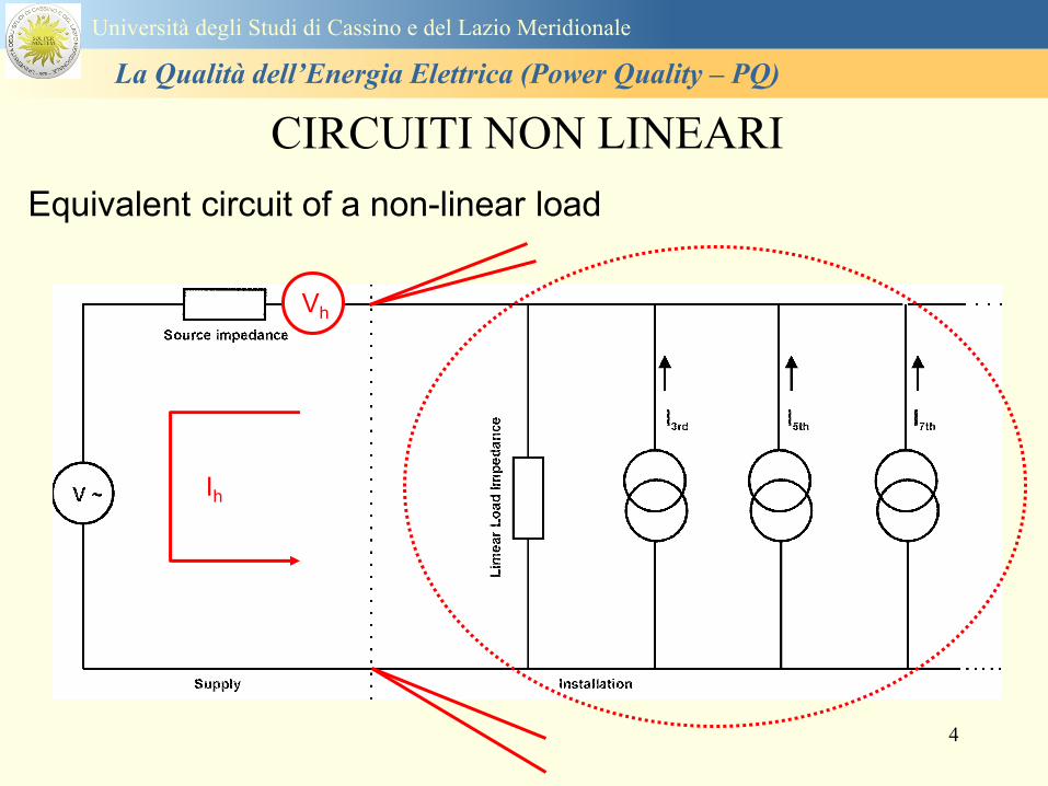
4
CIRCUITI NON LINEARI
Equivalent circuit of a non-linear load
Ih
Vh
Universitagrave degli Studi di Cassino e del Lazio Meridionale
La Qualitagrave dellrsquoEnergia Elettrica (Power Quality ndash PQ)
5
Power quality
problems
Turn off the mixer love
the monitorrsquos flickering
again
are
usually of
terrestrial
origin
Universitagrave degli Studi di Cassino e del Lazio Meridionale
La Qualitagrave dellrsquoEnergia Elettrica (Power Quality ndash PQ)
6
Universitagrave degli Studi di Cassino e del Lazio Meridionale
La Qualitagrave dellrsquoEnergia Elettrica (Power Quality ndash PQ)
Dobbiamo separare gli eventi di power quality dagli altri
problemi
bullSe avete delle apparecchiature sensibili
bullDisservizi inaspettati e intermittentihellip
bullQualrsquoegrave la causa dei disservizi o guasti
Software bug Cattive connessioni
Errori delloperatore Temperatura
Screpolature nei materiali Umiditagrave
Bolle nellacqua di raffreddamento
ecc ecc
ndashOppure egrave un disturbo power quality
7
Universitagrave degli Studi di Cassino Corso di Fondamenti di Misure
La Qualitagrave dellrsquoEnergia Elettrica (Power Quality ndash PQ)
Tensione costante e pari alla nominale
Frequenza costante e pari alla nominale
Tensioni e correnti sinusoidali
Continuitagrave del servizio
Le condizioni ideali
I ldquodisturbirdquo rappresentano lo scostamento
dei parametri elettrici dai valori ideali e la
non continuitagrave del servizio
La valutazione complessiva di questi
aspetti egrave denominata Power Quality
8
The good
old days bull
bull Ideal
three-phase
system
voltage
Three balanced
ohmic-inductive
single-phase loads
on the three phase
mains
-150A
-100A
-50A
0A
50A
100A
150A
0ms 5ms 10ms 15ms 20ms
t
i
i1 (L1)
i1 (L2)
i1 (L3)
-350V
-250V
-150V
-50V
50V
150V
250V
350V
0ms 5ms 10ms 15ms 20ms
t
u u1 (L1)
u1 (L2)
u1 (L3 )
Universitagrave degli Studi di Cassino e del Lazio Meridionale
La Qualitagrave dellrsquoEnergia Elettrica (Power Quality ndash PQ)
9
Distorsione armonica
Interruzioni del servizio
Abbassamenti di tensione e sovratensioni
Buchi di tensione
Transitori
Frequenza nominale della tensione fornita
Flicker - variazioni rapide della tensione
Squilibrio delle tensioni
Universitagrave degli Studi di Cassino e del Lazio Meridionale
La Qualitagrave dellrsquoEnergia Elettrica (Power Quality ndash PQ)
10
IEC 61000-2-22002 Electromagnetic compatibility (EMC) ndash Part 2-2 Environment ndash
Compatibility levels for low-frequency conducted disturbances and signalling in public
lowvoltage power supply systems
IEC 61000-2-4 Electromagnetic compatibility (EMC) ndash Part 2-4 Environment ndash
Compatibility levels in industrial plants for low-frequency conducted disturbances
IEC 61000-3-8 Electromagnetic compatibility (EMC) ndash Part 3 Limits ndash Section 8 Signalling
on low-voltage electrical installations ndash Emission levels frequency bands and electromagnetic
disturbance levels
IEC 61000-4-42004 Electromagnetic compatibility (EMC) ndash Part 4-4 Testing and
measurement techniques ndash Electrical fast transientburst immunity test
IEC 61000-4-72002 Electromagnetic compatibility (EMC) ndash Part 4-7 Testing and
measurement techniques ndash General guide on harmonics and interharmonics measurements
and instrumentation for power supply systems and equipment connected thereto
IEC 61000-4-302008 Electromagnetic compatibility (EMC) ndash Part 4-30 Testing and
measurement techniques ndash Power quality measurement methods
IEC 61000-4-15 Electromagnetic compatibility (EMC) ndash Part 4 Testing and measurement
techniques ndash Section 15 Flickermeter ndash Functional and design specifications
IEC 61180 (all parts) High-voltage test techniques for low voltage equipment
Normativa di riferimento
Universitagrave degli Studi di Cassino e del Lazio Meridionale
La Qualitagrave dellrsquoEnergia Elettrica (Power Quality ndash PQ)
11
IEC 61000 - 4 ndash 30 Norm
Seri 61000 Electromagnetic Compatibility
International Electrotechnical Commission
Part 4 Test and Measurement Tecniques
Section 30 PQ measurement methods
IEC 61000 - 4 ndash 7 Norm
Section 7 General guide on harmonics
and interharmonics measurements and
instrumentation for power supply
systems and equipment connected
thereto
Part 2 Environment ndashCompatibility levels
Seri 61000 Electromagnetic Compatibility
IEC International Electrotechnical Commission
Section xx details on the application sector
Part 3 Limits
Part 4 Test and Measurement Tecniques
Universitagrave degli Studi di Cassino e del Lazio Meridionale
La Qualitagrave dellrsquoEnergia Elettrica (Power Quality ndash PQ)
12
EN 501602010-07 Caratteristiche della tensione fornita dalle reti pubbliche di distribuzione
dellrsquoenergia elettrica
Descrive e specifica le caratteristiche principali della tensione ai terminali di
alimentazione di un utente della rete pubblica in bassa media e alta tensione in corrente
alternata in normali condizioni di esercizio Essa descrive i limiti o valori entro i quali le
caratteristiche della tensione possono essere attesi ai punti di alimentazione da reti elettriche
pubbliche europee e non descrive la situazione media sperimentata da un singolo utente di rete
Le caratteristiche della tensione fornite nella presente Norma non sono utilizzabili ai fini dei
limiti di EMC o di disturbi condotti nella rete pubblica Esse non sono utilizzabili ai fini di
prescrizioni nelle norme di prodotto o nelle norme per impianti
Normativa di riferimento
Universitagrave degli Studi di Cassino e del Lazio Meridionale
La Qualitagrave dellrsquoEnergia Elettrica (Power Quality ndash PQ)
13
Nel dettaglio la norma EN 50160 definisce i seguenti parametri
1 Frequenza nominale della tensione fornita
2 Ampiezza della tensione di alimentazione
3 Variazioni della tensione di alimentazione
4 Flicker - variazioni rapide della tensione
5 Buchi di tensione
6 Interruzioni della tensione di alimentazione
7 Squilibrio della tensione di alimentazione
8 Tensioni armoniche THD e fino al 25deg ordine
Universitagrave degli Studi di Cassino e del Lazio Meridionale
La Qualitagrave dellrsquoEnergia Elettrica (Power Quality ndash PQ)
14
Si specifica che qualora lrsquoazienda distributrice installi un registratore
della qualitagrave delle caratteristiche della tensione diverse dalle
interruzioni senza preavviso lunghe brevi e transitorie lo strumento
deve essere conforme alla norma tecnica EN 61000-4-30
Richiami nella delibera 042004
dellAUTORITA PER LENERGIA ELETTRICA E IL GAS
Il 30 gennaio 2004 con delibera 404 lrsquoautoritagrave dellrsquoenergia ha indicato tra i vari
argomenti trattati i criteri di misura delle qualitagrave della tensione
Nellrsquoarticolo 39 (pagina 29) viene indicato nel punto 391 e 2 che per la
registrazione di interruzioni senza preavviso lunghe brevi e transitorie occorre
utilizzare un registratore conforme alla CEI EN 50160 In questo caso lo strumento
registratore dice quando e per quanto si ha unrsquointerruzione del servizio ma a tutti gli
effetti NON EFFETTUA UNrsquoOSSERVAZIONE QUALITATIVA dei parametri
Universitagrave degli Studi di Cassino e del Lazio Meridionale
La Qualitagrave dellrsquoEnergia Elettrica (Power Quality ndash PQ)
15
Universitagrave degli Studi di Cassino e del Lazio Meridionale
La Qualitagrave dellrsquoEnergia Elettrica (Power Quality ndash PQ)
16
17
Universitagrave degli Studi di Cassino e del Lazio Meridionale
La Qualitagrave dellrsquoEnergia Elettrica (Power Quality ndash PQ)
CURVA DI TOLLERANZA AI DISTURBI
18
Caratteristiche dellrsquoalimentazione a bassa tensione
Universitagrave degli Studi di Cassino e del Lazio Meridionale
La Qualitagrave dellrsquoEnergia Elettrica (Power Quality ndash PQ)
19
Caratteristiche dellrsquoalimentazione a bassa tensione
Frequenza nominale
La frequenza nominale della tensione fornita deve essere di 50 Hz In condizioni normali
di esercizio il valore medio misurato nellrsquointervallo di 10 secondi deve essere
Per i sistemi con collegamento sincrono ad un sistema interconnesso
1 50 Hz plusmn 1 durante il 95 di un anno
2 50 Hz +4 - 6 durante il 100 di un anno
Per i sistemi senza collegamento sincrono ad un sistema interconnesso
1 50 Hz plusmn 2 durante il 95 di un anno
2 50 Hz plusmn 15 durante il 100 di un anno
Universitagrave degli Studi di Cassino e del Lazio Meridionale
La Qualitagrave dellrsquoEnergia Elettrica (Power Quality ndash PQ)
20
Caratteristiche dellrsquoalimentazione a bassa tensione
Universitagrave degli Studi di Cassino e del Lazio Meridionale
La Qualitagrave dellrsquoEnergia Elettrica (Power Quality ndash PQ)
21
Caratteristiche dellrsquoalimentazione a bassa tensione
Universitagrave degli Studi di Cassino e del Lazio Meridionale
La Qualitagrave dellrsquoEnergia Elettrica (Power Quality ndash PQ)
22
Variazioni della tensione di alimentazione (variazioni lente)
Le variazioni lente sono deviazioni ldquomedierdquo dal valore nominale dellrsquoampiezza della
tensione di consegna entro una fascia predefinita (per esempio del plusmn10) rispetto alla
tensione dichiarata
CAUSE variazione lenta dei carichi e dalla corrispondente azione di regolazione effettuata dai
variatori sotto carico dei trasformatori
Universitagrave degli Studi di Cassino e del Lazio Meridionale
La Qualitagrave dellrsquoEnergia Elettrica (Power Quality ndash PQ)
23
Variazioni della tensione di alimentazione (variazioni rapide)
Le variazioni rapide sono abbassamenti (o aumenti) bruschi di qualche percento della
tensione preesistente generalmente seguiti se abbassamenti da un ritorno (a rampa o di
altra forma) ad un valore intermedio tra quello preesistente e tra il minimo raggiunto
CAUSE commutazione dei carichi (partenza motori in particolare) funzionamento di carichi
con ciclo operativo particolarmente variabile e in qualche caso da manovre in rete (linee
trasformatori condensatori ecc)
Universitagrave degli Studi di Cassino e del Lazio Meridionale
La Qualitagrave dellrsquoEnergia Elettrica (Power Quality ndash PQ)
24
Flicker Il flicker egrave originato dalla fluttuazione della tensione Si definisce fluttuazione di tensione una
serie di variazioni rapide (uguali o diverse) della tensione
Fluttuazioni di tensione che presentano frequenze di modulazione del 50 Hz comprese tra 05 e
40 Hz danno origine al fenomeno del flicker (sfarfallio) ovvero della sensazione visiva
provocata dalle fluttuazioni dellrsquointensitagrave di illuminazione delle lampade
I suoi principali effetti sullrsquouomo possono essere mal di testa irritabilitagrave e fastidio agli occhi
Universitagrave degli Studi di Cassino e del Lazio Meridionale
La Qualitagrave dellrsquoEnergia Elettrica (Power Quality ndash PQ)
25
Universitagrave degli Studi di Cassino e del Lazio Meridionale
La Qualitagrave dellrsquoEnergia Elettrica (Power Quality ndash PQ)
26
La Qualitagrave dellrsquoEnergia Elettrica (Power Quality ndash PQ)
Universitagrave degli Studi di Cassino e del Lazio Meridionale
La Qualitagrave dellrsquoEnergia Elettrica (Power Quality ndash PQ)
27
Universitagrave degli Studi di Cassino e del Lazio Meridionale
La Qualitagrave dellrsquoEnergia Elettrica (Power Quality ndash PQ)
28
Universitagrave degli Studi di Cassino e del Lazio Meridionale
La Qualitagrave dellrsquoEnergia Elettrica (Power Quality ndash PQ)
29
Universitagrave degli Studi di Cassino e del Lazio Meridionale
La Qualitagrave dellrsquoEnergia Elettrica (Power Quality ndash PQ)
30
Universitagrave degli Studi di Cassino e del Lazio Meridionale
La Qualitagrave dellrsquoEnergia Elettrica (Power Quality ndash PQ)
31
Universitagrave degli Studi di Cassino e del Lazio Meridionale
La Qualitagrave dellrsquoEnergia Elettrica (Power Quality ndash PQ)
32
Buchi di tensione Riduzione temporanea della tensione in un punto della rete elettrica sotto una determinata
soglia Se durante un buco la tensione scende sotto una soglia di interruzione lrsquoevento egrave
considerato essere sia un buco che unrsquointerruzione
CAUSE I buchi di tensione sono generalmente dovuti a guasti che sopravvengono negli
impianti utilizzatori o nel sistema di distribuzione pubblico Possono dipendere anche variazioni
di carico lungo la linea
Universitagrave degli Studi di Cassino e del Lazio Meridionale
La Qualitagrave dellrsquoEnergia Elettrica (Power Quality ndash PQ)
33
Interruzioni della tensione di alimentazione Condizione in cui la tensione ad un terminale della rete egrave inferiore allrsquo1 della tensione
nominale per una durata fino a tre minuti (brevi) o maggiori di 3 minuti (lunghe)
Universitagrave degli Studi di Cassino e del Lazio Meridionale
La Qualitagrave dellrsquoEnergia Elettrica (Power Quality ndash PQ)
34
Sovratensioni temporanee alla frequenza di rete fra fasi e terra Le sovratensioni sono sopraelevazioni della tensione conseguenti a modificazioni dello
stato elettrico della rete elettrica
Universitagrave degli Studi di Cassino e del Lazio Meridionale
La Qualitagrave dellrsquoEnergia Elettrica (Power Quality ndash PQ)
35
Armoniche Le armoniche sono tensioni o correnti sinusoidali con frequenza pari ad un multiplo intero
(ordine) della frequenza fondamentale di funzionamento del sistema elettrico la cui
presenza determina una distorsione della forma drsquoonda della tensione di alimentazione
CAUSE In piccola parte dal sistema stesso (trasformatori etc) e per la maggior parte da
apparecchi utilizzatori carichi commutati elettronicamente raddrizzatori convertitori regolatori
in AC cicloconvertitori ecc carichi con caratteristiche non lineari apparecchiature a
saturazione magnetica lampade a scarica forni ad arco saldatrici ad arco trasformatori ecc
bull carichi inseriti e disinseriti da organi di manovra condensatori filtri e motori a induzione
Universitagrave degli Studi di Cassino e del Lazio Meridionale
La Qualitagrave dellrsquoEnergia Elettrica (Power Quality ndash PQ)
36
Armoniche di tensione e corrente ndash Problemi
Vi sono diversi ambiti causati dalle armoniche
bull problemi causati da armoniche di corrente
1048707 sovraccarico del neutro
1048707 aumento delle perdite nei trasformatori
1048707 interventi intempestivi degli interruttori automatici
1048707 aumento dellrsquoeffetto pelle
bull problemi causati da armoniche di tensione
1048707 deformazione della tensione
1048707 disturbi nella coppia dei motori ad induzione
1048707 rumore al passaggio per lo zero
bull problemi causati quando le armoniche di corrente raggiungono lrsquoalimentazione
Universitagrave degli Studi di Cassino e del Lazio Meridionale
La Qualitagrave dellrsquoEnergia Elettrica (Power Quality ndash PQ)
37
38
Universitagrave degli Studi di Cassino e del Lazio Meridionale
La Qualitagrave dellrsquoEnergia Elettrica (Power Quality ndash PQ)
39
Strumentazione ldquohand heldrdquo con display
Universitagrave degli Studi di Cassino e del Lazio Meridionale
La Qualitagrave dellrsquoEnergia Elettrica (Power Quality ndash PQ)
40
Strumentazione ldquohand heldrdquo con display
Universitagrave degli Studi di Cassino e del Lazio Meridionale
La Qualitagrave dellrsquoEnergia Elettrica (Power Quality ndash PQ)
41
Strumentazione da registrazione
Universitagrave degli Studi di Cassino e del Lazio Meridionale
La Qualitagrave dellrsquoEnergia Elettrica (Power Quality ndash PQ)
42
Schema di principio ndash 61000-4-30 copy IEC2008
The electrical quantity to be measured may be either directly accessible as is
generally the case in low-voltage systems or accessible via measurement
transducers
An instrument may include the whole measurement chain In this standard the
normative part does not consider the measurement transducers external to the
instrument and their associated uncertainty
Universitagrave degli Studi di Cassino e del Lazio Meridionale
La Qualitagrave dellrsquoEnergia Elettrica (Power Quality ndash PQ)
43
Universitagrave degli Studi di Cassino Corso di Fondamenti di Misure
La Qualitagrave dellrsquoEnergia Elettrica (Power Quality ndash PQ)
Classi dei metodi di misura - 61000-4-30 copy IEC2008
For each class measurement methods and appropriate performance requirements
are included
Sono definite tre classi A S e B
Class A
This class is used where precise measurements are necessary for example for contractual
applications that may require resolving disputes verifying compliance with standards etc
Any measurements of a parameter carried out with two different instruments complying with
the requirements of Class A when measuring the same signals will produce matching results
within the specified uncertainty for that parameter
Class S
This class is used for statistical applications such as surveys or power quality assessment
possibly with a limited subset of parameters Although it uses equivalent intervals of
measurement as class A the class S processing requirements are lower
Class B
This class is defined in order to avoid making many existing instruments designs obsolete
NOTE Class B methods are not recommended for new designs Readers are advised that Class B may be removed in a
future Edition of this standard
44
Classi dei metodi di misura - 61000-4-30 copy IEC2008
Measurement aggregation over time intervals
CLASS A
The basic measurement time interval for parameter magnitudes (supply voltage harmonics
interharmonics and unbalance) shall be a 10-cycle time interval for a 50 Hz power system
or 12-cycle time interval for a 60 Hz power system
The 1012-cycle measurement shall be re-synchronized at every RTC 10 min tick
The 1012-cycle values are then aggregated over 3 additional intervals
ndash 150180-cycle interval (150 cycles for 50 Hz nominal or 180 cycles for 60 Hz nominal)
ndash 10 min interval
ndash 2 h interval
CLASS S
Same time intervals as Class A
CLASS B
The manufacturer shall specify the number and duration of aggregation time intervals
Universitagrave degli Studi di Cassino e del Lazio Meridionale
La Qualitagrave dellrsquoEnergia Elettrica (Power Quality ndash PQ)
45
Universitagrave degli Studi di Cassino e del Lazio Meridionale
La Qualitagrave dellrsquoEnergia Elettrica (Power Quality ndash PQ)
46
Universitagrave degli Studi di Cassino e del Lazio Meridionale
La Qualitagrave dellrsquoEnergia Elettrica (Power Quality ndash PQ)
Class A
The 10-min aggregated value shall be tagged with the absolute time (for
example 01H1000) The time tag is the time at the conclusion of the 10-min
aggregation
The data for the 10-min time interval shall be aggregated from 1012-cycle time
intervals
Each 10-minute interval shall begin on a UTC 10-min tick The 10-min tick is
also used to re-synchronize the 1012-cycle intervals and the 150180-cycle
intervals
The final 1012-cycle interval(s) in a 10-min aggregation period will typically
overlap in time with the UTC 10-min clock tick Any overlapping 1012-cycle
interval (Overlap 1 in Figure 2) is included in the aggregation of the previous
10-min interval
47
Universitagrave degli Studi di Cassino e del Lazio Meridionale
La Qualitagrave dellrsquoEnergia Elettrica (Power Quality ndash PQ)
48
Universitagrave degli Studi di Cassino e del Lazio Meridionale
La Qualitagrave dellrsquoEnergia Elettrica (Power Quality ndash PQ)
49
Classi dei metodi di misura - 61000-4-30 copy IEC2008
Real time clock (RTC) uncertainty
Sono definite le specifiche per le 3 classi
Flagging concept
During a dip swell or interruption the measurement algorithm for other
parameters (for example frequency measurement) might produce an unreliable
value The flagging concept therefore avoids counting a single event more than
once in different parameters (for example counting a single dip as both a dip and a
frequency variation) and indicates that an aggregated value might be unreliable
Universitagrave degli Studi di Cassino e del Lazio Meridionale
La Qualitagrave dellrsquoEnergia Elettrica (Power Quality ndash PQ)
50
Classi dei metodi di misura - 61000-4-30 copy IEC2008
Power quality parameters - INDICES
Per ogni parametro viene suggerito il metodo di misura per le tre classi e
(soprattutto) le caratteristiche di precisione Per alcuni parametri rimanda a
specifiche norme (ad esempio Flicker e Armonicheinterarmoniche)
Esempio - Power frequency Class A
The frequency reading shall be obtained every 10 s As power frequency may not be exactly 50 Hz or 60
Hz within the 10 s time clock interval the number of cycles may not be an integer number The
fundamental frequency output is the ratio of the number of integral cycles counted during the 10 s time
clock interval divided by the cumulative duration of the integer cycles Before each assessment
harmonics and interharmonics shall be attenuated to minimize the effects of multiple zero crossings
The measurement time intervals shall be non-overlapping Individual cycles that overlap the 10 s time
clock are discarded Each 10 s interval shall begin on an absolute 10 s time clock with uncertainty as
defined in 46
Other techniques that provide equivalent results such as convolution are acceptable
Class S Same as class A
Class B The manufacturer shall specify the process used for frequency measurement
Universitagrave degli Studi di Cassino e del Lazio Meridionale
La Qualitagrave dellrsquoEnergia Elettrica (Power Quality ndash PQ)
51
Classi dei metodi di misura - 61000-4-30 copy IEC2008
Power quality parameters - INDICES
Per ogni parametro viene suggerito il metodo di misura per le tre classi e
(soprattutto) le caratteristiche di precisione Per alcuni parametri rimanda a
specifiche norme (ad esempio Flicker e Armonicheinterarmoniche)
Esempio - Power frequency
Measurement uncertainty and measuring range
ndash Class A
Under the conditions described in 61 the measurement uncertainty shall not exceed
plusmn10 mHz over the measuring ranges 425 Hz ~ 575 Hz 51 Hz ~ 69 Hz
ndash Class S
Under the conditions described in 61 the measurement uncertainty shall not exceed
plusmn50 mHz over the measuring ranges 425 Hz ~ 575 Hz 51 Hz ~ 69 Hz
ndash Class B
The manufacturer shall specify the uncertainty over the measuring ranges 425 Hz ~
575 Hz 51 Hz ~ 69 Hz
Universitagrave degli Studi di Cassino e del Lazio Meridionale
La Qualitagrave dellrsquoEnergia Elettrica (Power Quality ndash PQ)
52
Magnitude of the supply voltage
Measurement method
ndash Class A
The measurement shall be the rms value of the voltage magnitude over
a 10-cycle time interval for 50 Hz power system or 12-cycle time
interval for 60 Hz power system Every 1012-cycle interval shall be
contiguous and not overlapping with adjacent 1012-cycle intervals
except as shown as Overlap 1 in Figure 2
NOTE 1 This specific measurement method is used for quasi-stationary signals and is
not used for the detection and measurement of disturbances dips swells voltage
interruptions and transients
NOTE 2 The rms value includes by definition harmonics interharmonics mains
signalling etc
- Class S same as Class A
Universitagrave degli Studi di Cassino e del Lazio Meridionale
La Qualitagrave dellrsquoEnergia Elettrica (Power Quality ndash PQ)
53
Magnitude of the supply voltage
Measurement uncertainty and measuring range
ndash Class A
Under the conditions described in Clause 6 the measurement uncertainty
shall not exceed plusmn01 of Udin over the range of 10 ~ 150 of Udin
ndash Class S
Under the conditions described in Clause 6 the measurement uncertainty
shall not exceed plusmn05 of Udin over the range of 20 ~ 120 of Udin
Universitagrave degli Studi di Cassino e del Lazio Meridionale
La Qualitagrave dellrsquoEnergia Elettrica (Power Quality ndash PQ)
54
Supply voltage dips and swells
Measurement method
ndash Class A
The basic measurement Urms of a voltage dip and swell shall be the
Urms(frac12) on each measurement channel (see Clause 322)
The cycle duration for Urms(frac12) depends on the frequency The
frequency might be determined by the last non-flagged power frequency
measurement (see Clause 47 and Clause 51) or by any other method
that yields the uncertainty requirements of Clause 6
NOTE 1 The Urms(frac12) value includes by definition harmonics interharmonics mains
signalling voltage etc
NOTE 2 It is important to avoid loss of data when dips and swells occur in a rapid
sequence (for example three events in one second with up to one minute between
sequences may occur when a recloser operates into a sustained fault) If during a rapid
burst the dipswell event characteristics cannot be recorded then a count of events may
be useful
Universitagrave degli Studi di Cassino e del Lazio Meridionale
La Qualitagrave dellrsquoEnergia Elettrica (Power Quality ndash PQ)
55
Supply voltage dips and swells
Detection and evaluation of a voltage dip
Voltage dip detection
The dip threshold is a percentage of either Udin or the sliding voltage
reference Usr (see 525 544) The user shall declare the reference
voltage in use
NOTE ndash On single-phase systems a voltage dip begins when the Urms voltage falls
below the dip threshold and ends when the Urms voltage is equal to or above the dip
threshold plus the hysteresis voltage
ndash On polyphase systems a dip begins when the Urms voltage of one or more channels is
below the dip threshold and ends when the Urms voltage on all measured channels is
equal to or above the dip threshold plus the hysteresis voltage
The dip threshold and the hysteresis voltage are both set by the user according to the
use
Universitagrave degli Studi di Cassino e del Lazio Meridionale
La Qualitagrave dellrsquoEnergia Elettrica (Power Quality ndash PQ)
56
Calculation of a sliding reference voltage
The sliding reference voltage implementation is optional not mandatory
If a sliding reference is chosen for voltage dip or swell detection this
shall be calculated using a first-order filter with a 1-min time constant
This filter is given by
Usr(n) = 09967 times Usr(nndash1) + 00033 times U(1012)rms
where
Usr(n) is the present value of the sliding reference voltage
Usr(nndash1) is the previous value of the sliding reference voltage and
U(1012)rms is the most recent 1012-cycle rms value
When the measurement is started the initial value of the sliding reference voltage is set
to the declared input voltage The sliding reference voltage is updated every 1012-
cycles If a 1012-cycle value is flagged the sliding reference voltage is not updated
and the previous value is used
Universitagrave degli Studi di Cassino e del Lazio Meridionale
La Qualitagrave dellrsquoEnergia Elettrica (Power Quality ndash PQ)
57
Supply voltage dips and swells
Voltage dip evaluation
A voltage dip is characterized by a pair of data either residual voltage
(Ures) or depth and duration
ndash the residual voltage of a voltage dip is the lowest Urms(frac12) value
measured on any channel during the dip
ndash the depth is the difference between the reference voltage (either Udin
or Usr) and the residual voltage It is generally expressed in percentage
of the reference voltage
NOTE 1 During the dip it may be useful to also record the lowest Urms(frac12) on each
channel in addition to the residual voltage of the dip The duration spent below the dip
threshold on each channel may also be useful
Universitagrave degli Studi di Cassino e del Lazio Meridionale
La Qualitagrave dellrsquoEnergia Elettrica (Power Quality ndash PQ)
58
Supply voltage dips and swells
Voltage dip evaluation
NOTE 2 If voltage waveforms are recorded before during and after a
dip useful information about phase angle changes may be available in
the recorded data
The start time of a dip shall be time stamped with the time of the start of
the Urms of the channel that initiated the event and the end time of the
dip shall be the time stamped with the time of the end of the Urms that
ended the event as defined by the threshold plus the hysteresis
The duration of a voltage dip is the time difference between the start
time and the end time of the voltage dip
Universitagrave degli Studi di Cassino e del Lazio Meridionale
La Qualitagrave dellrsquoEnergia Elettrica (Power Quality ndash PQ)
59
Supply voltage dips and swells
Residual voltage and swell voltage magnitude measurement
uncertainty
ndash Class A
The measurement uncertainty shall not exceed plusmn02 of Udin
ndash Class S
The measurement uncertainty shall not exceed plusmn10 of Udin
Universitagrave degli Studi di Cassino e del Lazio Meridionale
La Qualitagrave dellrsquoEnergia Elettrica (Power Quality ndash PQ)
60
Schema di principio ndash 61000-4-7 copy IEC2002
Universitagrave degli Studi di Cassino e del Lazio Meridionale
La Qualitagrave dellrsquoEnergia Elettrica (Power Quality ndash PQ)
61
Universitagrave degli Studi di Cassino e del Lazio Meridionale
La Qualitagrave dellrsquoEnergia Elettrica (Power Quality ndash PQ)
62
Universitagrave degli Studi di Cassino e del Lazio Meridionale
La Qualitagrave dellrsquoEnergia Elettrica (Power Quality ndash PQ)
63
Inter-Armoniche Le inter-armoniche sono tensioni o correnti sinusoidali con frequenza diversa da un
multiplo intero della fondamentale la cui presenza determina una distorsione
(modulazione) della forma donda della tensione di alimentazione
CAUSE dai carichi che assorbono correnti inter-armoniche
- carichi commutati elettronicamente convertitori cascata subsincrona cicloconvertitori regolatori con
controllo a pacchetti di cicli ecc
- carichi con caratteristiche non lineari eo non stazionarie forni ad arco saldatrici ad arco ecc
Universitagrave degli Studi di Cassino e del Lazio Meridionale
La Qualitagrave dellrsquoEnergia Elettrica (Power Quality ndash PQ)
64
Universitagrave degli Studi di Cassino e del Lazio Meridionale
La Qualitagrave dellrsquoEnergia Elettrica (Power Quality ndash PQ)
Un porsquo di esempi e
consigli praticihellip
65
0V
50V
100V
150V
200V
250V
300V
350V
0ms 5ms 10ms 15ms 20ms
t
u
0A
1A
2A
3A
i
0V
50V
100V
150V
200V
250V
300V
350V
0ms 5ms 10ms 15ms 20ms
t
u
0A
1A
2A
3A
i
0V
50V
100V
150V
200V
250V
300V
350V
0ms 5ms 10ms 15ms 20ms
t
u
0A
1A
2A
3A
i
gleichgerichtete
Netzspannung
Kondensator-
spannung
gleichgerichteter
Netzstrom
The situation
today
bull Computed current and voltage profiles when a
230 V 58 W fluorescent lamp with an old-style
electronic ballast is driven on the phase wire of
a typical power distribution system
System voltage 230 V
System frequency 50 Hz
Source resistance 500 mW
Longitudinal induction 904 microH
System impedance 575 mW
Mean dc current 180 mA
Smoothing capacitance220 microF
66
And what about electronic ballasts that are rated over 25W
Introduce electronic power factor correction (PFC)
0V
20V
40V
60V
80V
100V
120V
140V
160V
180V
200V
220V
0deg 15deg 30deg 45deg
u
00A
03A
06A
09A
12A
i
67
Though todayrsquos ballasts are better if
rated gt25 W bull Only
the
small
ones
continu
e to
pollute
just like
PCs
TV sets
do
68
This leads to a number of
previously unknown effects bull 1 Deformed voltage curves
bull 2 Huge inrush current peaks
bull 3 Instrument dependent measured parameters
bull 4 Increased loading of phase conductors
bull 5 Loading and overloading of the neutral conductor
bull 6 Overheating and start-up problems of induction motors
bull 7 Additional stray losses in transformers
bull 8 Repercussions of generators upon the mains
bull 9 Influence of capacitors repercussions upon the mains
and four additional complications in TN-C systems
10 Stray currents in equipotential bonding system magnetic fields
11 Contamination of data streams by stray currents
12 Stray currents in the earthing system corrosion damage
13 Lightning currents in devices and equipment
69
1 Deformed voltage curves
bull in theory
-350V
-300V
-250V
-200V
-150V
-100V
-50V
0V
50V
100V
150V
200V
250V
300V
350V
0 5 10 15 20
t ms
u
System voltage profile when driving
a single-phase load comprising
twenty 58 W energy-saver lamps in
parallel on a typical 230 V power
system
70
and in practice
bull An actual
current profile
bull
bull and
bull a voltage profile
bull
bull recorded in a large storage
dispatch and administrative
building
71
at home or in industrial environments
bull
bull Television 40
W
bull 200 Vdiv 2
Adiv
bull 5 msdiv
Harmonic
spectrum
Frequency
converter
50 Adiv
Phase currents
I1=I2=I3=160 A
IN=295 A
5 msdiv
72
Every periodic waveform can be written
as the infinite sum of sinusoidal waves
-175
-150
-125
-100
-75
-50
-25
0
25
50
75
100
125
150
175
0 5 10 15 20
t ms
i
mA
itot
i1
Synthesis of a triangular current profile 100mA
Content fundamental I = 99 mA Isup2 = 9855 mAsup2
Sum of squares Isup2 = 9855 mAsup2
Root of sum = RMS value I = 99 mA
-175
-150
-125
-100
-75
-50
-25
0
25
50
75
100
125
150
175
0 5 10 15 20
t ms
i
mA
itot
i1
i3
Synthesis of a triangular current profile 100mA
Content fundamental I = 99 mA Isup2 = 9855 mAsup2
Cont 3 rd harmonic I = -11 mA Isup2 = 122 mAsup2
Sum of squares Isup2 = 9977 mAsup2
Root of sum = RMS value I = 100 mA
-175
-150
-125
-100
-75
-50
-25
0
25
50
75
100
125
150
175
0 5 10 15 20
t ms
i
mA
itot
i1
i3
i5
Synthesis of a triangular current profile 100mA
Content fundamental I = 99 mA Isup2 = 9855 mAsup2
Cont 3 rd harmonic I = -11 mA Isup2 = 122 mAsup2
Cont 5 th harmonic I = 4 mA Isup2 = 16 mAsup2
Sum of squares Isup2 = 9993 mAsup2
Root of sum = RMS value I = 100 mA
-175
-150
-125
-100
-75
-50
-25
0
25
50
75
100
125
150
175
0 5 10 15 20
t ms
i
mA
itot
i1
i3
i5
i7
Synthesis of a triangular current profile 100mA
Content fundamental I = 99 mA Isup2 = 9855 mAsup2
Cont 3 rd harmonic I = -11 mA Isup2 = 122 mAsup2
Cont 5 th harmonic I = 4 mA Isup2 = 16 mAsup2
Cont 7 th harmonic I = -2 mA Isup2 = 4 mAsup2
Sum of squares Isup2 = 9997 mAsup2
Root of sum = RMS value I = 100 mA
-175
-150
-125
-100
-75
-50
-25
0
25
50
75
100
125
150
175
0 5 10 15 20
t ms
i
mA
itot i1
i3 i5
i7 i9
Synthesis of a triangular current profile 100mA
Content fundamental I = 99 mA Isup2 = 9855 mAsup2
Cont 3 rd harmonic I = -11 mA Isup2 = 122 mAsup2
Cont 5 th harmonic I = 4 mA Isup2 = 16 mAsup2
Cont 7 th harmonic I = -2 mA Isup2 = 4 mAsup2
Cont 9 th harmonic I = 1 mA Isup2 = 2 mAsup2
Sum of squares Isup2 = 9998 mAsup2
Root of sum = RMS value I = 100 mA
-175
-150
-125
-100
-75
-50
-25
0
25
50
75
100
125
150
175
0 5 10 15 20
t ms
i
mA
itot i1
i3 i5
i7 i9
i11
Synthesis of a triangular current profile 100mA
Content fundamental I = 99 mA Isup2 = 9855 mAsup2
Cont 3 rd harmonic I = -11 mA Isup2 = 122 mAsup2
Cont 5 th harmonic I = 4 mA Isup2 = 16 mAsup2
Cont 7 th harmonic I = -2 mA Isup2 = 4 mAsup2
Cont 9 th harmonic I = 1 mA Isup2 = 2 mAsup2
Cont 11 th harmonic I = -1 mA Isup2 = 1 mAsup2
Sum of squares Isup2 = 9999 mAsup2
Root of sum = RMS value I = 100 mA
-175
-150
-125
-100
-75
-50
-25
0
25
50
75
100
125
150
175
0 5 10 15 20
t ms
i
mA
itot i1
i3 i5
i7 i9
i11 i13
Synthesis of a triangular current profile 100mA
Content fundamental I = 99 mA Isup2 = 9855 mAsup2
Cont 3 rd harmonic I = -11 mA Isup2 = 122 mAsup2
Cont 5 th harmonic I = 4 mA Isup2 = 16 mAsup2
Cont 7 th harmonic I = -2 mA Isup2 = 4 mAsup2
Cont 9 th harmonic I = 1 mA Isup2 = 2 mAsup2
Cont 11 th harmonic I = -1 mA Isup2 = 1 mAsup2
Cont 13 th harmonic I = 1 mA Isup2 = 0 mAsup2
Sum of squares Isup2 = 9999 mAsup2
Root of sum = RMS value I = 100 mA
-175
-150
-125
-100
-75
-50
-25
0
25
50
75
100
125
150
175
0 5 10 15 20
t ms
i
mA
itot i1
i3 i5
i7 i9
i11 i13
i15
Synthesis of a triangular current profile 100mA
Content fundamental I = 99 mA Isup2 = 9855 mAsup2
Cont 3 rd harmonic I = -11 mA Isup2 = 122 mAsup2
Cont 5 th harmonic I = 4 mA Isup2 = 16 mAsup2
Cont 7 th harmonic I = -2 mA Isup2 = 4 mAsup2
Cont 9 th harmonic I = 1 mA Isup2 = 2 mAsup2
Cont 11 th harmonic I = -1 mA Isup2 = 1 mAsup2
Cont 13 th harmonic I = 1 mA Isup2 = 0 mAsup2
Cont 15 th harmonic I = 0 mA Isup2 = 0 mAsup2
Sum of squares Isup2 = 10000 mAsup2
Root of sum = RMS value I = 100 mA
-175
-150
-125
-100
-75
-50
-25
0
25
50
75
100
125
150
175
0 5 10 15 20
t ms
i
mA
itot i1
i3 i5
i7 i9
i11 i13
i15 i17
Synthesis of a triangular current profile 100mA
Content fundamental I = 99 mA Isup2 = 9855 mAsup2
Cont 3 rd harmonic I = -11 mA Isup2 = 122 mAsup2
Cont 5 th harmonic I = 4 mA Isup2 = 16 mAsup2
Cont 7 th harmonic I = -2 mA Isup2 = 4 mAsup2
Cont 9 th harmonic I = 1 mA Isup2 = 2 mAsup2
Cont 11 th harmonic I = -1 mA Isup2 = 1 mAsup2
Cont 13 th harmonic I = 1 mA Isup2 = 0 mAsup2
Cont 15 th harmonic I = 0 mA Isup2 = 0 mAsup2
Cont 17 th harmonic I = 0 mA Isup2 = 0 mAsup2
Sum of squares Isup2 = 10000 mAsup2
Root of sum = RMS value I = 100 mA
73
whose frequencies called harmonics are
integer multiples of the fundamental frequency
-175
-150
-125
-100
-75
-50
-25
0
25
50
75
100
125
150
175
0 5 10 15 20
t ms
i
mA
itot
i1
Synthesis of a rectangular current profile 100mA
Content fundamental I = 90 mA Isup2 = 8106 mAsup2
Sum of squares Isup2 = 8106 mAsup2
Root of sum = RMS value I = 90 mA
-175
-150
-125
-100
-75
-50
-25
0
25
50
75
100
125
150
175
0 5 10 15 20
t ms
i
mA
itot
i1
i3
Synthesis of a rectangular current profile 100mA
Content fundamental I = 90 mA Isup2 = 8106 mAsup2
Cont 3 rd harmonic I = 30 mA Isup2 = 901 mAsup2
Sum of squares Isup2 = 9006 mAsup2
Root of sum = RMS value I = 95 mA
-175
-150
-125
-100
-75
-50
-25
0
25
50
75
100
125
150
175
0 5 10 15 20
t ms
i
mA
itot
i1
i3
i5
Synthesis of a rectangular current profile 100mA
Content fundamental I = 90 mA Isup2 = 8106 mAsup2
Cont 3 rd harmonic I = 30 mA Isup2 = 901 mAsup2
Cont 5 th harmonic I = 18 mA Isup2 = 324 mAsup2
Sum of squares Isup2 = 9331 mAsup2
Root of sum = RMS value I = 97 mA
-175
-150
-125
-100
-75
-50
-25
0
25
50
75
100
125
150
175
0 5 10 15 20
t ms
i
mA
itot
i1
i3
i5
i7
Synthesis of a rectangular current profile 100mA
Content fundamental I = 90 mA Isup2 = 8106 mAsup2
Cont 3 rd harmonic I = 30 mA Isup2 = 901 mAsup2
Cont 5 th harmonic I = 18 mA Isup2 = 324 mAsup2
Cont 7 th harmonic I = 13 mA Isup2 = 165 mAsup2
Sum of squares Isup2 = 9496 mAsup2
Root of sum = RMS value I = 97 mA
-175
-150
-125
-100
-75
-50
-25
0
25
50
75
100
125
150
175
0 5 10 15 20
t ms
i
mA
itot i1
i3 i5
i7 i9
Synthesis of a rectangular current profile 100mA
Content fundamental I = 90 mA Isup2 = 8106 mAsup2
Cont 3 rd harmonic I = 30 mA Isup2 = 901 mAsup2
Cont 5 th harmonic I = 18 mA Isup2 = 324 mAsup2
Cont 7 th harmonic I = 13 mA Isup2 = 165 mAsup2
Cont 9 th harmonic I = 10 mA Isup2 = 100 mAsup2
Sum of squares Isup2 = 9596 mAsup2
Root of sum = RMS value I = 98 mA
-175
-150
-125
-100
-75
-50
-25
0
25
50
75
100
125
150
175
0 5 10 15 20
t ms
i
mA
itot i1
i3 i5
i7 i9
i11
Synthesis of a rectangular current profile 100mA
Content fundamental I = 90 mA Isup2 = 8106 mAsup2
Cont 3 rd harmonic I = 30 mA Isup2 = 901 mAsup2
Cont 5 th harmonic I = 18 mA Isup2 = 324 mAsup2
Cont 7 th harmonic I = 13 mA Isup2 = 165 mAsup2
Cont 9 th harmonic I = 10 mA Isup2 = 100 mAsup2
Cont 11 th harmonic I = 8 mA Isup2 = 67 mAsup2
Sum of squares Isup2 = 9663 mAsup2
Root of sum = RMS value I = 98 mA
-175
-150
-125
-100
-75
-50
-25
0
25
50
75
100
125
150
175
0 5 10 15 20
t ms
i
mA
itot i1
i3 i5
i7 i9
i11 i13
Synthesis of a rectangular current profile 100mA
Content fundamental I = 90 mA Isup2 = 8106 mAsup2
Cont 3 rd harmonic I = 30 mA Isup2 = 901 mAsup2
Cont 5 th harmonic I = 18 mA Isup2 = 324 mAsup2
Cont 7 th harmonic I = 13 mA Isup2 = 165 mAsup2
Cont 9 th harmonic I = 10 mA Isup2 = 100 mAsup2
Cont 11 th harmonic I = 8 mA Isup2 = 67 mAsup2
Cont 13 th harmonic I = 7 mA Isup2 = 48 mAsup2
Sum of squares Isup2 = 9711 mAsup2
Root of sum = RMS value I = 99 mA
-175
-150
-125
-100
-75
-50
-25
0
25
50
75
100
125
150
175
0 5 10 15 20
t ms
i
mA
itot i1
i3 i5
i7 i9
i11 i13
i15
Synthesis of a rectangular current profile 100mA
Content fundamental I = 90 mA Isup2 = 8106 mAsup2
Cont 3 rd harmonic I = 30 mA Isup2 = 901 mAsup2
Cont 5 th harmonic I = 18 mA Isup2 = 324 mAsup2
Cont 7 th harmonic I = 13 mA Isup2 = 165 mAsup2
Cont 9 th harmonic I = 10 mA Isup2 = 100 mAsup2
Cont 11 th harmonic I = 8 mA Isup2 = 67 mAsup2
Cont 13 th harmonic I = 7 mA Isup2 = 48 mAsup2
Cont 15 th harmonic I = 6 mA Isup2 = 36 mAsup2
Sum of squares Isup2 = 9747 mAsup2
Root of sum = RMS value I = 99 mA
-175
-150
-125
-100
-75
-50
-25
0
25
50
75
100
125
150
175
0 5 10 15 20
t ms
i
mA
itot i1
i3 i5
i7 i9
i11 i13
i15 i17
Synthesis of a rectangular current profile 100mA
Content fundamental I = 90 mA Isup2 = 8106 mAsup2
Cont 3 rd harmonic I = 30 mA Isup2 = 901 mAsup2
Cont 5 th harmonic I = 18 mA Isup2 = 324 mAsup2
Cont 7 th harmonic I = 13 mA Isup2 = 165 mAsup2
Cont 9 th harmonic I = 10 mA Isup2 = 100 mAsup2
Cont 11 th harmonic I = 8 mA Isup2 = 67 mAsup2
Cont 13 th harmonic I = 7 mA Isup2 = 48 mAsup2
Cont 15 th harmonic I = 6 mA Isup2 = 36 mAsup2
Cont 17 th harmonic I = 5 mA Isup2 = 28 mAsup2
Sum of squares Isup2 = 9775 mAsup2
Root of sum = RMS value I = 99 mA
74
Even far better simulations are
available free of charge at
bull wwwpowerstandardscomMcEachern
75
-4A
-3A
-2A
-1A
0A
1A
2A
3A
4A
0ms 5ms 10ms 15ms 20ms
t
i
-4A
-3A
-2A
-1A
0A
1A
2A
3A
4A
0ms 5ms 10ms 15ms 20ms
t
i
Applying the Fourier
analysis to a real PC
current does not work
directly
bull
bull but it can be
modelled by a similar
triangular curve in
which not all of the
higher harmonics
have been included
Triangular current profile of
the same amplitude and a
pulse duty cycle of 17
Input current of a PC
with monitor
76
Analysis of the model triangular waveform
-400
-350
-300
-250
-200
-150
-100
-50
0
50
100
150
200
250
300
350
400
0 5 10 15 20
t ms
iI
itot(t) L1 [A] i1(t) L1 [A]
i3(t) L1 [A] i5(t) L1 [A]
i7(t) L1 [A] i9(t) L1 [A]
i11(t) L1 [A] i13(t) L1 [A]
i15(t) L1 [A] i17(t) L1 [A]
77
M3
Harmonics
Energy
(active
power)
L1
L2
L3
N
PE
Important
bull Harmonics are created within the loads
themselves and can flow ldquoupstreamrdquo to
contaminate the power system
78
-6A
-5A
-4A
-3A
-2A
-1A
0A
1A
2A
3A
4A
5A
6A
0ms 5ms 10ms 15ms 20ms
t
i
Squared values
Without
Fundamental 502 mA 251986 mAsup2 the fundamental
3rd harmonic -479 mA 229000 mAsup2 229000 mAsup2
5th harmonic 434 mA 188595 mAsup2 188595 mAsup2
7th harmonic -374 mA 139903 mAsup2 139903 mAsup2
9th harmonic 304 mA 92527 mAsup2 92527 mAsup2
11th harmonic -232 mA 53671 mAsup2 53671 mAsup2
13th harmonic 163 mA 26600 mAsup2 26600 mAsup2
15th harmonic -104 mA 10780 mAsup2 10780 mAsup2
17th harmonic 57 mA 3299 mAsup2 3299 mAsup2
Sum of the squares 996362 mAsup2 744377 mAsup2
Root thereof 998 mAeff THD = 863 mA
What actually is THD Example shown here triangular current
profile with an rms current of 1000 mA
and a pulse duty cycle of 17
THDr (root mean square) = 863mA1000mA = 86
THDf (fundamental) = 863mA502mA = 172
79
Effect on phase-to-neutral
and phase-to-phase voltages
bull Recorded
on June
30 2002
230 p
m
bull What
was the
matter
then
bull The
soccer
final
Germany
vs
Brazil
80
The triple-N harmonics drive
a circulating current in the
delta winding of a distribution
transformer
bull but the
bull voltage harmonics
propagate into the next
low-voltage power
distribution system
81 0V
50V
100V
150V
200V
250V
300V
350V
400V
450V
500V
550V
0 10 20 30 40 50
t ms
u
0A
10A
20A
30A
40A
50A
60A
70A
80A
90A
100A
110A
120A
130A
140A
150A
i
Switching on just as supply voltage passes through zero
0V
50V
100V
150V
200V
250V
300V
350V
400V
450V
500V
550V
0 10 20 30 40 50
t ms
u
0A
10A
20A
30A
40A
50A
60A
70A
80A
90A
100A
110A
120A
130A
140A
150A
i
Switching on just as supply voltage is at its peak
2 Huge inrush current peaks
ndash in theory
82
and in practice
bull Inrush current of a
compact energy-
saver lamp and its
effect on the system
voltage (recorded at
the Technical
University of
Budapest)
bull
83
enables us to infer what
happens when run by a
normal three-phase supply
The same fluorescent lamp
with a magnetic ballast
bull The behaviour measured
when connected to
a dc supply
bull
Behaviour of a 58 W fluorescent lamp connected to a dc
supply
0
20
40
60
80
100
120
140
160
180
200
0 200 400 600 800 1000 1200
i mA
u
V
Measurement
Behaviour of a 58 W fluorescent lamp connected to a dc
supply
0
20
40
60
80
100
120
140
160
180
200
0 200 400 600 800 1000 1200
i mA
u
V
MeasurementCalculation
-350
-300
-250
-200
-150
-100
-50
0
50
100
150
200
250
300
350
0 5 10 15 20
t ms
u
V
-10
-08
-06
-04
-02
00
02
04
06
08
10
i
A
Systems voltage
Current
-350
-300
-250
-200
-150
-100
-50
0
50
100
150
200
250
300
350
0 5 10 15 20
t ms
u
V
-10
-08
-06
-04
-02
00
02
04
06
08
10
i
A
Systems voltage
Lamp voltage
Current
84
Warning ldquoCompensationrdquo is not
always what you think it is
bull Distinguish
between
bull Reactive
power
compensatio
n
aka power
factor
correction
Remedial
measure
Parallel (or
sometimes series)
compensation
using capacitors
Filter circuits
tuned to the
individual harmonic
frequencies
Harmonic
compensation
85
5 (Over)loading the neutral conductor
bull Magnetic ballast Old-style electronic ballast
-25A
-20A
-15A
-10A
-05A
00A
05A
10A
15A
20A
25A
0 5 10 15 20
t ms i
i(t) N
-25A
-20A
-15A
-10A
-05A
00A
05A
10A
15A
20A
25A
0 5 10 15 20
t ms
i
i(t) N
-25A
-20A
-15A
-10A
-05A
00A
05A
10A
15A
20A
25A
0 5 10 15 20
t ms
i
i(t) L1 i(t) L2 i(t) L3
-25A
-20A
-15A
-10A
-05A
00A
05A
10A
15A
20A
25A
0 5 10 15 20
t ms
i
i(t) L1
i(t) L2
i(t) L3
86
Adding the 3rd
harmonics
in the
neutral
wire
-150-100-50
050
100150
0deg 30deg 60deg 90deg 120deg 150deg 180deg 210deg 240deg 270deg 300deg 330deg 360deg
L1
-150-100-50
050
100150
0deg 30deg 60deg 90deg 120deg 150deg 180deg 210deg 240deg 270deg 300deg 330deg 360deg
L2
-150-100-50
050
100150
0deg 30deg 60deg 90deg 120deg 150deg 180deg 210deg 240deg 270deg 300deg 330deg 360deg
L3
-450-400-350-300-250-200-150-100-50
050
100150200250300350400450
0deg 30deg 60deg 90deg 120deg 150deg 180deg 210deg 240deg 270deg 300deg 330deg 360deg
f
iicirc
N
Physics dictates
that at any
moment in time
the phase and
neutral currents
must sum to zero
87
Effect on a three-phase ac motor
appears almost identical
bull The same motor is being
driven
simultaneously in
these three modes
homopolar system
zero-sequence system
direct system
positive-sequence system
inverse system
negative-sequence system
88
The transformer
influences the load
89
but the load also effects
the transformer
Total transformer loss is
2
)()(
nom
nomCunomFeLossI
IPPP
While total transformer loss really is
2
)(
2
)(
2
)(
nomnom
nomad
nom
nomCu
nom
nomFeLossI
I
f
fP
I
IP
U
UPP
90
6 ldquosupplementaryrdquo additional losses
in transformers
can be calculated rapidly
using the following two
simple formulae 50
2
2
1
2
11
Nn
n
nqh
I
In
I
I
e
eK
50
1
2
1
1
50
1
2
Nn
n
nNn
n
nI
IIII
where
Oh well
perhaps a practical
example is clearer
1000 compact 11W
(15VA) energy-saver
lamps powered by a
15kVA transformer
uSC=4 Pa=01PCu
Harmonics of an Osram Dulux 11W
CFL and a serial impedance of
R =291Ω amp X L=113Ω
U U sup2 I L I Lsup2 P aP Cu
n V Vsup2 mA mAsup2
1 2302 529920 485 23523 56
3 83 689 371 13764 295
5 107 1145 203 4121 245
7 43 185 53 281 33
9 11 12 30 90 17
11 23 53 38 144 42
13 10 10 15 23 09
15 06 04 15 23 12
17 11 12 15 23 15
19 05 03 09 08 07
21 05 03 13 17 18
23 06 04 08 06 08
25 04 02 06 04 05
27 06 04 08 06 11
29 04 02 05 03 05
31 03 01 05 03 06
33 03 01 05 03 06
35 03 01 04 02 05
37 03 01 04 02 05
39 03 01 03 01 03
41 01 00 03 01 04
43 02 00 02 00 02
45 01 00 02 00 02
47 01 00 02 00 02
49 01 00 01 00 01
51 01 00 01 00 01
P aP Cu = 814814
etc
etc
91
Harmonics measurement on an
Osram Dulux 11W compact
fluorescent lamp
U U sup2 I L I Lsup2 P addP Cu
n V Vsup2 mA mAsup2
1 2327 541493 489 23912 37
3 06 04 391 15288 215
5 44 194 264 6970 273
7 23 53 200 4000 307
9 01 00 192 3686 467
11 01 00 166 2756 522
13 01 00 127 1613 427
15 01 00 110 1210 426
17 01 00 102 1040 471
19 01 00 87 757 428
21 01 00 77 593 409
23 01 00 73 533 441
25 01 00 61 372 364
27 01 00 49 240 274
29 01 00 42 176 232
31 01 00 36 130 195
33 01 00 30 90 153
35 01 00 33 109 209
37 01 00 31 96 206
39 01 00 25 63 149
41 01 00 25 63 164
43 01 00 25 63 181
45 01 00 19 36 114
47 01 00 18 32 112
49 01 00 19 36 136
51 01 00 16 26 104
P aP Cu = 7017
To some extent
the transformer
protects itself
bull Always remember to
consider it
bull If the influence of the
transformer upon the load
did not exist then the
influence of the load upon
the transformer would be
nearly 9 times as high
7017
etc
etc
92
Rule of thumb Select transformers 35
larger than specification by apparent
power would require
bull This suffices to err
on the safe side
even in the worst
case and can
hardly ever be
wrong since
maximum
efficiency always
lies between 25
and 50 of rated
load
Efficiency of a 1 MVA transformer plotted against loading
985
986
987
988
989
990
991
992
993
994
0 25 50 75 100 125
Relative load h
Design with max Cu loss and min Fe loss
Design with min Cu loss and max Fe loss
1 MVA oil transformer according to HD 428
93
Measured response of an 11 W
fluorescent lamp operated with a
magnetic ballast
94
We are
dealing with
a complex
problem
bull These
effects
are not
isolated
but are
mutuall
y inter-
depende
nt
Effects 2 3 and 5 can be demonstrated
on DKIrsquos display panel
95
A conventional approximately resistive-
inductive load
mA
N L1 L2 L3
Two conventional approximately
resistive-inductive loads Three conventional approximately
resistive-inductive loads
96
A modern electronic load
mA
N
Two modern electronic loads Three modern electronic loads
L1 L2 L3
97
Discoveries on a
refurbished
junction box
System voltage
(as trigger
signal)
Current in the
earthing
conductor
between the
consumer unit
and the
bonding
busbar
98
The TN-C system that was perfectly
adequate some years ago is unable to meet
present-day requirements
-6
-4
-2
0
2
4
6
0 5 10 15 20
t ms
i
A
-350
-300
-250
-200
-150
-100
-50
0
50
100
150
200
250
300
350
0 5 10 15 20
t ms
u
V
99
ldquoTHFrdquo
(third harmonic
filter) made in
Finland
In certain situations this affordable
filter can be of help
German
version ldquoTHXrdquo
100
0Ω
5 Ω
1 0 Ω
1 5 Ω
2 0 Ω
2 5 Ω
3 0 Ω
3 5 Ω
4 0 Ω
0Hz 50Hz 100Hz 150Hz 200Hz 250Hz 300Hz
f
Z
-90deg
-75deg
-60deg
-45deg
-30deg
-15deg
0deg
15deg
30deg
45deg
60deg
75deg
90deg
φ
Reactorreactance
Capacitorreactance
Parallelimpedace
Phase angle
Data and frequency response
of the filter
bull 1320 microF
bull 875
14 mW microH
101
The filter in use
bull In a nursery running sodium vapour lamps (500 kW)
In a typical office and administrative building
102
The EMC Transformer from Switzerland
7 The effects of stray magnetic fields
in TN-C systems
bull ldquoWhen we build transformers the first thing we focus on is complying with our customersrsquo
requirements and only then on complying with standards Why Because it is customer
needs and not standards that offer real scope for product innovationrdquo
103
8 In a TN-C system problems arise from data
streams and working currents mixing
bull Others who
have drawn
attention to
this source of
data
transmission
errors include
engineering
and insurance
companies experts
consultants and many
others besides
104
9 Increased corrosive damage
bull This (once) galvanized steel strip ndash the earth
electrode of a TN-C-S system ndash was located close
to the transformer station
Side facing
transformer
station
Side facing
transformer
station
Side facing away
from transformer
station
Side facing away
from transformer
station
105
bull WRONG RIGHT
Working currents have no place
in earthing systems and
protective conductors
106
10 Lightning currents
107
Which bridge to
cross which bridge to
burn
Sometimes you just donlsquot
believe what you see
This one will soon
look rather charred
IEC 60364-5-54
54343 If from any point of the installation the neutral and protective
functions are provided by separate conductors it is not permitted to
connect the neutral conductor to any other earthed part of the
installation
108
Well then the rest is no longer a
miracle
109
110
111
Another means of (over)loading the
neutral conductor
bull dc currents
Original ldquoFakerdquo
112
and their
effects U = 2285 V
I = 92 mA
P = 182 W
S = 209 VA
Q = 103 VAr
LF = 087
cos φ = 099
U = 2243 V
I = 126 A
P = 380 W
S = 2860 VA
Q = 2830 VAr
No-load current in a
toroidal-core
transformer
200 VA
-350-300
-250-200
-150-100
-500
50
100150
200250
300350
0 10 20 30 40
t ms
u
V
-12
-10
-8
-6
-4
-2
0
2
4
6
8
10
12
i
mA
Voltage
Current
No-load current in a toroidal-core
transformer 200 VA when
running a 1500 W
hairdryer at
half-power
in parallel
-350-300
-250-200
-150-100
-500
50
100150
200250
300350
0 5 10 15 20 25 30 35 40
t ms
u
V
-6
-5
-4
-3
-2
-1
0
1
2
3
4
5
6
i
A
Voltage
Current
113
The later models donlsquot do it any more
The EN 61000-3-2 has at least managed
to put an end to this approach
Domestic appliances Max 105 A of 2nd harmonic
114
An electrical engineering wonder
dc current generates ac voltage
115
Spicing things up with a pinch of HF
electronic halogen lamp transformers
116
Decorative HF reactors
117
Current and power loss as a function of voltage
00
02
04
06
08
10
12
14
16
18
0 40 80 120 160 200 240
U V
I
A
0
20
40
60
80
100
120
PV
W
I [A]
Pv [W]
Power loss capacitor voltage
and total voltage as a function of current
0
50
100
150
200
250
300
350
400
450
000 025 050 075 100 125 150
I A
U
V
0
5
10
15
20
25
30
35
40
45
50
PV
W
Utot [V] Eff
UR [V] Eff
Pv [W]
The passive
harmonic filter
made of readily
available
components
bull is both
reliable
118
and effective
bull befor
e
bull after
119
Half the solution has already been implemented
120
And if thatrsquos not enough
bull Passive filter circuits will do it
121
So what do we need to do
bull In low-voltage power distribution systems
Do not use cables in which the neutral or protective earth conductor has a
reduced cross-section
Use only 5-core cable Do not install TN-C- or TN-C-S systems
Be generous when dimensioning conductor cross-sections This helps to
reduce line voltage drops and thus reduces the effect of current distortions on
the voltage as well as lowering energy losses (see VDE 0298 Part 100)
Generously dimensioned conductors will have no problem coping with any
future increase in demand
Only use measuring instruments that display the true root mean square value
(TRMS meters)
In medium-voltage power distribution systems
Use a varied mix of distribution transformers with different vector groups
5
Power quality
problems
Turn off the mixer love
the monitorrsquos flickering
again
are
usually of
terrestrial
origin
Universitagrave degli Studi di Cassino e del Lazio Meridionale
La Qualitagrave dellrsquoEnergia Elettrica (Power Quality ndash PQ)
6
Universitagrave degli Studi di Cassino e del Lazio Meridionale
La Qualitagrave dellrsquoEnergia Elettrica (Power Quality ndash PQ)
Dobbiamo separare gli eventi di power quality dagli altri
problemi
bullSe avete delle apparecchiature sensibili
bullDisservizi inaspettati e intermittentihellip
bullQualrsquoegrave la causa dei disservizi o guasti
Software bug Cattive connessioni
Errori delloperatore Temperatura
Screpolature nei materiali Umiditagrave
Bolle nellacqua di raffreddamento
ecc ecc
ndashOppure egrave un disturbo power quality
7
Universitagrave degli Studi di Cassino Corso di Fondamenti di Misure
La Qualitagrave dellrsquoEnergia Elettrica (Power Quality ndash PQ)
Tensione costante e pari alla nominale
Frequenza costante e pari alla nominale
Tensioni e correnti sinusoidali
Continuitagrave del servizio
Le condizioni ideali
I ldquodisturbirdquo rappresentano lo scostamento
dei parametri elettrici dai valori ideali e la
non continuitagrave del servizio
La valutazione complessiva di questi
aspetti egrave denominata Power Quality
8
The good
old days bull
bull Ideal
three-phase
system
voltage
Three balanced
ohmic-inductive
single-phase loads
on the three phase
mains
-150A
-100A
-50A
0A
50A
100A
150A
0ms 5ms 10ms 15ms 20ms
t
i
i1 (L1)
i1 (L2)
i1 (L3)
-350V
-250V
-150V
-50V
50V
150V
250V
350V
0ms 5ms 10ms 15ms 20ms
t
u u1 (L1)
u1 (L2)
u1 (L3 )
Universitagrave degli Studi di Cassino e del Lazio Meridionale
La Qualitagrave dellrsquoEnergia Elettrica (Power Quality ndash PQ)
9
Distorsione armonica
Interruzioni del servizio
Abbassamenti di tensione e sovratensioni
Buchi di tensione
Transitori
Frequenza nominale della tensione fornita
Flicker - variazioni rapide della tensione
Squilibrio delle tensioni
Universitagrave degli Studi di Cassino e del Lazio Meridionale
La Qualitagrave dellrsquoEnergia Elettrica (Power Quality ndash PQ)
10
IEC 61000-2-22002 Electromagnetic compatibility (EMC) ndash Part 2-2 Environment ndash
Compatibility levels for low-frequency conducted disturbances and signalling in public
lowvoltage power supply systems
IEC 61000-2-4 Electromagnetic compatibility (EMC) ndash Part 2-4 Environment ndash
Compatibility levels in industrial plants for low-frequency conducted disturbances
IEC 61000-3-8 Electromagnetic compatibility (EMC) ndash Part 3 Limits ndash Section 8 Signalling
on low-voltage electrical installations ndash Emission levels frequency bands and electromagnetic
disturbance levels
IEC 61000-4-42004 Electromagnetic compatibility (EMC) ndash Part 4-4 Testing and
measurement techniques ndash Electrical fast transientburst immunity test
IEC 61000-4-72002 Electromagnetic compatibility (EMC) ndash Part 4-7 Testing and
measurement techniques ndash General guide on harmonics and interharmonics measurements
and instrumentation for power supply systems and equipment connected thereto
IEC 61000-4-302008 Electromagnetic compatibility (EMC) ndash Part 4-30 Testing and
measurement techniques ndash Power quality measurement methods
IEC 61000-4-15 Electromagnetic compatibility (EMC) ndash Part 4 Testing and measurement
techniques ndash Section 15 Flickermeter ndash Functional and design specifications
IEC 61180 (all parts) High-voltage test techniques for low voltage equipment
Normativa di riferimento
Universitagrave degli Studi di Cassino e del Lazio Meridionale
La Qualitagrave dellrsquoEnergia Elettrica (Power Quality ndash PQ)
11
IEC 61000 - 4 ndash 30 Norm
Seri 61000 Electromagnetic Compatibility
International Electrotechnical Commission
Part 4 Test and Measurement Tecniques
Section 30 PQ measurement methods
IEC 61000 - 4 ndash 7 Norm
Section 7 General guide on harmonics
and interharmonics measurements and
instrumentation for power supply
systems and equipment connected
thereto
Part 2 Environment ndashCompatibility levels
Seri 61000 Electromagnetic Compatibility
IEC International Electrotechnical Commission
Section xx details on the application sector
Part 3 Limits
Part 4 Test and Measurement Tecniques
Universitagrave degli Studi di Cassino e del Lazio Meridionale
La Qualitagrave dellrsquoEnergia Elettrica (Power Quality ndash PQ)
12
EN 501602010-07 Caratteristiche della tensione fornita dalle reti pubbliche di distribuzione
dellrsquoenergia elettrica
Descrive e specifica le caratteristiche principali della tensione ai terminali di
alimentazione di un utente della rete pubblica in bassa media e alta tensione in corrente
alternata in normali condizioni di esercizio Essa descrive i limiti o valori entro i quali le
caratteristiche della tensione possono essere attesi ai punti di alimentazione da reti elettriche
pubbliche europee e non descrive la situazione media sperimentata da un singolo utente di rete
Le caratteristiche della tensione fornite nella presente Norma non sono utilizzabili ai fini dei
limiti di EMC o di disturbi condotti nella rete pubblica Esse non sono utilizzabili ai fini di
prescrizioni nelle norme di prodotto o nelle norme per impianti
Normativa di riferimento
Universitagrave degli Studi di Cassino e del Lazio Meridionale
La Qualitagrave dellrsquoEnergia Elettrica (Power Quality ndash PQ)
13
Nel dettaglio la norma EN 50160 definisce i seguenti parametri
1 Frequenza nominale della tensione fornita
2 Ampiezza della tensione di alimentazione
3 Variazioni della tensione di alimentazione
4 Flicker - variazioni rapide della tensione
5 Buchi di tensione
6 Interruzioni della tensione di alimentazione
7 Squilibrio della tensione di alimentazione
8 Tensioni armoniche THD e fino al 25deg ordine
Universitagrave degli Studi di Cassino e del Lazio Meridionale
La Qualitagrave dellrsquoEnergia Elettrica (Power Quality ndash PQ)
14
Si specifica che qualora lrsquoazienda distributrice installi un registratore
della qualitagrave delle caratteristiche della tensione diverse dalle
interruzioni senza preavviso lunghe brevi e transitorie lo strumento
deve essere conforme alla norma tecnica EN 61000-4-30
Richiami nella delibera 042004
dellAUTORITA PER LENERGIA ELETTRICA E IL GAS
Il 30 gennaio 2004 con delibera 404 lrsquoautoritagrave dellrsquoenergia ha indicato tra i vari
argomenti trattati i criteri di misura delle qualitagrave della tensione
Nellrsquoarticolo 39 (pagina 29) viene indicato nel punto 391 e 2 che per la
registrazione di interruzioni senza preavviso lunghe brevi e transitorie occorre
utilizzare un registratore conforme alla CEI EN 50160 In questo caso lo strumento
registratore dice quando e per quanto si ha unrsquointerruzione del servizio ma a tutti gli
effetti NON EFFETTUA UNrsquoOSSERVAZIONE QUALITATIVA dei parametri
Universitagrave degli Studi di Cassino e del Lazio Meridionale
La Qualitagrave dellrsquoEnergia Elettrica (Power Quality ndash PQ)
15
Universitagrave degli Studi di Cassino e del Lazio Meridionale
La Qualitagrave dellrsquoEnergia Elettrica (Power Quality ndash PQ)
16
17
Universitagrave degli Studi di Cassino e del Lazio Meridionale
La Qualitagrave dellrsquoEnergia Elettrica (Power Quality ndash PQ)
CURVA DI TOLLERANZA AI DISTURBI
18
Caratteristiche dellrsquoalimentazione a bassa tensione
Universitagrave degli Studi di Cassino e del Lazio Meridionale
La Qualitagrave dellrsquoEnergia Elettrica (Power Quality ndash PQ)
19
Caratteristiche dellrsquoalimentazione a bassa tensione
Frequenza nominale
La frequenza nominale della tensione fornita deve essere di 50 Hz In condizioni normali
di esercizio il valore medio misurato nellrsquointervallo di 10 secondi deve essere
Per i sistemi con collegamento sincrono ad un sistema interconnesso
1 50 Hz plusmn 1 durante il 95 di un anno
2 50 Hz +4 - 6 durante il 100 di un anno
Per i sistemi senza collegamento sincrono ad un sistema interconnesso
1 50 Hz plusmn 2 durante il 95 di un anno
2 50 Hz plusmn 15 durante il 100 di un anno
Universitagrave degli Studi di Cassino e del Lazio Meridionale
La Qualitagrave dellrsquoEnergia Elettrica (Power Quality ndash PQ)
20
Caratteristiche dellrsquoalimentazione a bassa tensione
Universitagrave degli Studi di Cassino e del Lazio Meridionale
La Qualitagrave dellrsquoEnergia Elettrica (Power Quality ndash PQ)
21
Caratteristiche dellrsquoalimentazione a bassa tensione
Universitagrave degli Studi di Cassino e del Lazio Meridionale
La Qualitagrave dellrsquoEnergia Elettrica (Power Quality ndash PQ)
22
Variazioni della tensione di alimentazione (variazioni lente)
Le variazioni lente sono deviazioni ldquomedierdquo dal valore nominale dellrsquoampiezza della
tensione di consegna entro una fascia predefinita (per esempio del plusmn10) rispetto alla
tensione dichiarata
CAUSE variazione lenta dei carichi e dalla corrispondente azione di regolazione effettuata dai
variatori sotto carico dei trasformatori
Universitagrave degli Studi di Cassino e del Lazio Meridionale
La Qualitagrave dellrsquoEnergia Elettrica (Power Quality ndash PQ)
23
Variazioni della tensione di alimentazione (variazioni rapide)
Le variazioni rapide sono abbassamenti (o aumenti) bruschi di qualche percento della
tensione preesistente generalmente seguiti se abbassamenti da un ritorno (a rampa o di
altra forma) ad un valore intermedio tra quello preesistente e tra il minimo raggiunto
CAUSE commutazione dei carichi (partenza motori in particolare) funzionamento di carichi
con ciclo operativo particolarmente variabile e in qualche caso da manovre in rete (linee
trasformatori condensatori ecc)
Universitagrave degli Studi di Cassino e del Lazio Meridionale
La Qualitagrave dellrsquoEnergia Elettrica (Power Quality ndash PQ)
24
Flicker Il flicker egrave originato dalla fluttuazione della tensione Si definisce fluttuazione di tensione una
serie di variazioni rapide (uguali o diverse) della tensione
Fluttuazioni di tensione che presentano frequenze di modulazione del 50 Hz comprese tra 05 e
40 Hz danno origine al fenomeno del flicker (sfarfallio) ovvero della sensazione visiva
provocata dalle fluttuazioni dellrsquointensitagrave di illuminazione delle lampade
I suoi principali effetti sullrsquouomo possono essere mal di testa irritabilitagrave e fastidio agli occhi
Universitagrave degli Studi di Cassino e del Lazio Meridionale
La Qualitagrave dellrsquoEnergia Elettrica (Power Quality ndash PQ)
25
Universitagrave degli Studi di Cassino e del Lazio Meridionale
La Qualitagrave dellrsquoEnergia Elettrica (Power Quality ndash PQ)
26
La Qualitagrave dellrsquoEnergia Elettrica (Power Quality ndash PQ)
Universitagrave degli Studi di Cassino e del Lazio Meridionale
La Qualitagrave dellrsquoEnergia Elettrica (Power Quality ndash PQ)
27
Universitagrave degli Studi di Cassino e del Lazio Meridionale
La Qualitagrave dellrsquoEnergia Elettrica (Power Quality ndash PQ)
28
Universitagrave degli Studi di Cassino e del Lazio Meridionale
La Qualitagrave dellrsquoEnergia Elettrica (Power Quality ndash PQ)
29
Universitagrave degli Studi di Cassino e del Lazio Meridionale
La Qualitagrave dellrsquoEnergia Elettrica (Power Quality ndash PQ)
30
Universitagrave degli Studi di Cassino e del Lazio Meridionale
La Qualitagrave dellrsquoEnergia Elettrica (Power Quality ndash PQ)
31
Universitagrave degli Studi di Cassino e del Lazio Meridionale
La Qualitagrave dellrsquoEnergia Elettrica (Power Quality ndash PQ)
32
Buchi di tensione Riduzione temporanea della tensione in un punto della rete elettrica sotto una determinata
soglia Se durante un buco la tensione scende sotto una soglia di interruzione lrsquoevento egrave
considerato essere sia un buco che unrsquointerruzione
CAUSE I buchi di tensione sono generalmente dovuti a guasti che sopravvengono negli
impianti utilizzatori o nel sistema di distribuzione pubblico Possono dipendere anche variazioni
di carico lungo la linea
Universitagrave degli Studi di Cassino e del Lazio Meridionale
La Qualitagrave dellrsquoEnergia Elettrica (Power Quality ndash PQ)
33
Interruzioni della tensione di alimentazione Condizione in cui la tensione ad un terminale della rete egrave inferiore allrsquo1 della tensione
nominale per una durata fino a tre minuti (brevi) o maggiori di 3 minuti (lunghe)
Universitagrave degli Studi di Cassino e del Lazio Meridionale
La Qualitagrave dellrsquoEnergia Elettrica (Power Quality ndash PQ)
34
Sovratensioni temporanee alla frequenza di rete fra fasi e terra Le sovratensioni sono sopraelevazioni della tensione conseguenti a modificazioni dello
stato elettrico della rete elettrica
Universitagrave degli Studi di Cassino e del Lazio Meridionale
La Qualitagrave dellrsquoEnergia Elettrica (Power Quality ndash PQ)
35
Armoniche Le armoniche sono tensioni o correnti sinusoidali con frequenza pari ad un multiplo intero
(ordine) della frequenza fondamentale di funzionamento del sistema elettrico la cui
presenza determina una distorsione della forma drsquoonda della tensione di alimentazione
CAUSE In piccola parte dal sistema stesso (trasformatori etc) e per la maggior parte da
apparecchi utilizzatori carichi commutati elettronicamente raddrizzatori convertitori regolatori
in AC cicloconvertitori ecc carichi con caratteristiche non lineari apparecchiature a
saturazione magnetica lampade a scarica forni ad arco saldatrici ad arco trasformatori ecc
bull carichi inseriti e disinseriti da organi di manovra condensatori filtri e motori a induzione
Universitagrave degli Studi di Cassino e del Lazio Meridionale
La Qualitagrave dellrsquoEnergia Elettrica (Power Quality ndash PQ)
36
Armoniche di tensione e corrente ndash Problemi
Vi sono diversi ambiti causati dalle armoniche
bull problemi causati da armoniche di corrente
1048707 sovraccarico del neutro
1048707 aumento delle perdite nei trasformatori
1048707 interventi intempestivi degli interruttori automatici
1048707 aumento dellrsquoeffetto pelle
bull problemi causati da armoniche di tensione
1048707 deformazione della tensione
1048707 disturbi nella coppia dei motori ad induzione
1048707 rumore al passaggio per lo zero
bull problemi causati quando le armoniche di corrente raggiungono lrsquoalimentazione
Universitagrave degli Studi di Cassino e del Lazio Meridionale
La Qualitagrave dellrsquoEnergia Elettrica (Power Quality ndash PQ)
37
38
Universitagrave degli Studi di Cassino e del Lazio Meridionale
La Qualitagrave dellrsquoEnergia Elettrica (Power Quality ndash PQ)
39
Strumentazione ldquohand heldrdquo con display
Universitagrave degli Studi di Cassino e del Lazio Meridionale
La Qualitagrave dellrsquoEnergia Elettrica (Power Quality ndash PQ)
40
Strumentazione ldquohand heldrdquo con display
Universitagrave degli Studi di Cassino e del Lazio Meridionale
La Qualitagrave dellrsquoEnergia Elettrica (Power Quality ndash PQ)
41
Strumentazione da registrazione
Universitagrave degli Studi di Cassino e del Lazio Meridionale
La Qualitagrave dellrsquoEnergia Elettrica (Power Quality ndash PQ)
42
Schema di principio ndash 61000-4-30 copy IEC2008
The electrical quantity to be measured may be either directly accessible as is
generally the case in low-voltage systems or accessible via measurement
transducers
An instrument may include the whole measurement chain In this standard the
normative part does not consider the measurement transducers external to the
instrument and their associated uncertainty
Universitagrave degli Studi di Cassino e del Lazio Meridionale
La Qualitagrave dellrsquoEnergia Elettrica (Power Quality ndash PQ)
43
Universitagrave degli Studi di Cassino Corso di Fondamenti di Misure
La Qualitagrave dellrsquoEnergia Elettrica (Power Quality ndash PQ)
Classi dei metodi di misura - 61000-4-30 copy IEC2008
For each class measurement methods and appropriate performance requirements
are included
Sono definite tre classi A S e B
Class A
This class is used where precise measurements are necessary for example for contractual
applications that may require resolving disputes verifying compliance with standards etc
Any measurements of a parameter carried out with two different instruments complying with
the requirements of Class A when measuring the same signals will produce matching results
within the specified uncertainty for that parameter
Class S
This class is used for statistical applications such as surveys or power quality assessment
possibly with a limited subset of parameters Although it uses equivalent intervals of
measurement as class A the class S processing requirements are lower
Class B
This class is defined in order to avoid making many existing instruments designs obsolete
NOTE Class B methods are not recommended for new designs Readers are advised that Class B may be removed in a
future Edition of this standard
44
Classi dei metodi di misura - 61000-4-30 copy IEC2008
Measurement aggregation over time intervals
CLASS A
The basic measurement time interval for parameter magnitudes (supply voltage harmonics
interharmonics and unbalance) shall be a 10-cycle time interval for a 50 Hz power system
or 12-cycle time interval for a 60 Hz power system
The 1012-cycle measurement shall be re-synchronized at every RTC 10 min tick
The 1012-cycle values are then aggregated over 3 additional intervals
ndash 150180-cycle interval (150 cycles for 50 Hz nominal or 180 cycles for 60 Hz nominal)
ndash 10 min interval
ndash 2 h interval
CLASS S
Same time intervals as Class A
CLASS B
The manufacturer shall specify the number and duration of aggregation time intervals
Universitagrave degli Studi di Cassino e del Lazio Meridionale
La Qualitagrave dellrsquoEnergia Elettrica (Power Quality ndash PQ)
45
Universitagrave degli Studi di Cassino e del Lazio Meridionale
La Qualitagrave dellrsquoEnergia Elettrica (Power Quality ndash PQ)
46
Universitagrave degli Studi di Cassino e del Lazio Meridionale
La Qualitagrave dellrsquoEnergia Elettrica (Power Quality ndash PQ)
Class A
The 10-min aggregated value shall be tagged with the absolute time (for
example 01H1000) The time tag is the time at the conclusion of the 10-min
aggregation
The data for the 10-min time interval shall be aggregated from 1012-cycle time
intervals
Each 10-minute interval shall begin on a UTC 10-min tick The 10-min tick is
also used to re-synchronize the 1012-cycle intervals and the 150180-cycle
intervals
The final 1012-cycle interval(s) in a 10-min aggregation period will typically
overlap in time with the UTC 10-min clock tick Any overlapping 1012-cycle
interval (Overlap 1 in Figure 2) is included in the aggregation of the previous
10-min interval
47
Universitagrave degli Studi di Cassino e del Lazio Meridionale
La Qualitagrave dellrsquoEnergia Elettrica (Power Quality ndash PQ)
48
Universitagrave degli Studi di Cassino e del Lazio Meridionale
La Qualitagrave dellrsquoEnergia Elettrica (Power Quality ndash PQ)
49
Classi dei metodi di misura - 61000-4-30 copy IEC2008
Real time clock (RTC) uncertainty
Sono definite le specifiche per le 3 classi
Flagging concept
During a dip swell or interruption the measurement algorithm for other
parameters (for example frequency measurement) might produce an unreliable
value The flagging concept therefore avoids counting a single event more than
once in different parameters (for example counting a single dip as both a dip and a
frequency variation) and indicates that an aggregated value might be unreliable
Universitagrave degli Studi di Cassino e del Lazio Meridionale
La Qualitagrave dellrsquoEnergia Elettrica (Power Quality ndash PQ)
50
Classi dei metodi di misura - 61000-4-30 copy IEC2008
Power quality parameters - INDICES
Per ogni parametro viene suggerito il metodo di misura per le tre classi e
(soprattutto) le caratteristiche di precisione Per alcuni parametri rimanda a
specifiche norme (ad esempio Flicker e Armonicheinterarmoniche)
Esempio - Power frequency Class A
The frequency reading shall be obtained every 10 s As power frequency may not be exactly 50 Hz or 60
Hz within the 10 s time clock interval the number of cycles may not be an integer number The
fundamental frequency output is the ratio of the number of integral cycles counted during the 10 s time
clock interval divided by the cumulative duration of the integer cycles Before each assessment
harmonics and interharmonics shall be attenuated to minimize the effects of multiple zero crossings
The measurement time intervals shall be non-overlapping Individual cycles that overlap the 10 s time
clock are discarded Each 10 s interval shall begin on an absolute 10 s time clock with uncertainty as
defined in 46
Other techniques that provide equivalent results such as convolution are acceptable
Class S Same as class A
Class B The manufacturer shall specify the process used for frequency measurement
Universitagrave degli Studi di Cassino e del Lazio Meridionale
La Qualitagrave dellrsquoEnergia Elettrica (Power Quality ndash PQ)
51
Classi dei metodi di misura - 61000-4-30 copy IEC2008
Power quality parameters - INDICES
Per ogni parametro viene suggerito il metodo di misura per le tre classi e
(soprattutto) le caratteristiche di precisione Per alcuni parametri rimanda a
specifiche norme (ad esempio Flicker e Armonicheinterarmoniche)
Esempio - Power frequency
Measurement uncertainty and measuring range
ndash Class A
Under the conditions described in 61 the measurement uncertainty shall not exceed
plusmn10 mHz over the measuring ranges 425 Hz ~ 575 Hz 51 Hz ~ 69 Hz
ndash Class S
Under the conditions described in 61 the measurement uncertainty shall not exceed
plusmn50 mHz over the measuring ranges 425 Hz ~ 575 Hz 51 Hz ~ 69 Hz
ndash Class B
The manufacturer shall specify the uncertainty over the measuring ranges 425 Hz ~
575 Hz 51 Hz ~ 69 Hz
Universitagrave degli Studi di Cassino e del Lazio Meridionale
La Qualitagrave dellrsquoEnergia Elettrica (Power Quality ndash PQ)
52
Magnitude of the supply voltage
Measurement method
ndash Class A
The measurement shall be the rms value of the voltage magnitude over
a 10-cycle time interval for 50 Hz power system or 12-cycle time
interval for 60 Hz power system Every 1012-cycle interval shall be
contiguous and not overlapping with adjacent 1012-cycle intervals
except as shown as Overlap 1 in Figure 2
NOTE 1 This specific measurement method is used for quasi-stationary signals and is
not used for the detection and measurement of disturbances dips swells voltage
interruptions and transients
NOTE 2 The rms value includes by definition harmonics interharmonics mains
signalling etc
- Class S same as Class A
Universitagrave degli Studi di Cassino e del Lazio Meridionale
La Qualitagrave dellrsquoEnergia Elettrica (Power Quality ndash PQ)
53
Magnitude of the supply voltage
Measurement uncertainty and measuring range
ndash Class A
Under the conditions described in Clause 6 the measurement uncertainty
shall not exceed plusmn01 of Udin over the range of 10 ~ 150 of Udin
ndash Class S
Under the conditions described in Clause 6 the measurement uncertainty
shall not exceed plusmn05 of Udin over the range of 20 ~ 120 of Udin
Universitagrave degli Studi di Cassino e del Lazio Meridionale
La Qualitagrave dellrsquoEnergia Elettrica (Power Quality ndash PQ)
54
Supply voltage dips and swells
Measurement method
ndash Class A
The basic measurement Urms of a voltage dip and swell shall be the
Urms(frac12) on each measurement channel (see Clause 322)
The cycle duration for Urms(frac12) depends on the frequency The
frequency might be determined by the last non-flagged power frequency
measurement (see Clause 47 and Clause 51) or by any other method
that yields the uncertainty requirements of Clause 6
NOTE 1 The Urms(frac12) value includes by definition harmonics interharmonics mains
signalling voltage etc
NOTE 2 It is important to avoid loss of data when dips and swells occur in a rapid
sequence (for example three events in one second with up to one minute between
sequences may occur when a recloser operates into a sustained fault) If during a rapid
burst the dipswell event characteristics cannot be recorded then a count of events may
be useful
Universitagrave degli Studi di Cassino e del Lazio Meridionale
La Qualitagrave dellrsquoEnergia Elettrica (Power Quality ndash PQ)
55
Supply voltage dips and swells
Detection and evaluation of a voltage dip
Voltage dip detection
The dip threshold is a percentage of either Udin or the sliding voltage
reference Usr (see 525 544) The user shall declare the reference
voltage in use
NOTE ndash On single-phase systems a voltage dip begins when the Urms voltage falls
below the dip threshold and ends when the Urms voltage is equal to or above the dip
threshold plus the hysteresis voltage
ndash On polyphase systems a dip begins when the Urms voltage of one or more channels is
below the dip threshold and ends when the Urms voltage on all measured channels is
equal to or above the dip threshold plus the hysteresis voltage
The dip threshold and the hysteresis voltage are both set by the user according to the
use
Universitagrave degli Studi di Cassino e del Lazio Meridionale
La Qualitagrave dellrsquoEnergia Elettrica (Power Quality ndash PQ)
56
Calculation of a sliding reference voltage
The sliding reference voltage implementation is optional not mandatory
If a sliding reference is chosen for voltage dip or swell detection this
shall be calculated using a first-order filter with a 1-min time constant
This filter is given by
Usr(n) = 09967 times Usr(nndash1) + 00033 times U(1012)rms
where
Usr(n) is the present value of the sliding reference voltage
Usr(nndash1) is the previous value of the sliding reference voltage and
U(1012)rms is the most recent 1012-cycle rms value
When the measurement is started the initial value of the sliding reference voltage is set
to the declared input voltage The sliding reference voltage is updated every 1012-
cycles If a 1012-cycle value is flagged the sliding reference voltage is not updated
and the previous value is used
Universitagrave degli Studi di Cassino e del Lazio Meridionale
La Qualitagrave dellrsquoEnergia Elettrica (Power Quality ndash PQ)
57
Supply voltage dips and swells
Voltage dip evaluation
A voltage dip is characterized by a pair of data either residual voltage
(Ures) or depth and duration
ndash the residual voltage of a voltage dip is the lowest Urms(frac12) value
measured on any channel during the dip
ndash the depth is the difference between the reference voltage (either Udin
or Usr) and the residual voltage It is generally expressed in percentage
of the reference voltage
NOTE 1 During the dip it may be useful to also record the lowest Urms(frac12) on each
channel in addition to the residual voltage of the dip The duration spent below the dip
threshold on each channel may also be useful
Universitagrave degli Studi di Cassino e del Lazio Meridionale
La Qualitagrave dellrsquoEnergia Elettrica (Power Quality ndash PQ)
58
Supply voltage dips and swells
Voltage dip evaluation
NOTE 2 If voltage waveforms are recorded before during and after a
dip useful information about phase angle changes may be available in
the recorded data
The start time of a dip shall be time stamped with the time of the start of
the Urms of the channel that initiated the event and the end time of the
dip shall be the time stamped with the time of the end of the Urms that
ended the event as defined by the threshold plus the hysteresis
The duration of a voltage dip is the time difference between the start
time and the end time of the voltage dip
Universitagrave degli Studi di Cassino e del Lazio Meridionale
La Qualitagrave dellrsquoEnergia Elettrica (Power Quality ndash PQ)
59
Supply voltage dips and swells
Residual voltage and swell voltage magnitude measurement
uncertainty
ndash Class A
The measurement uncertainty shall not exceed plusmn02 of Udin
ndash Class S
The measurement uncertainty shall not exceed plusmn10 of Udin
Universitagrave degli Studi di Cassino e del Lazio Meridionale
La Qualitagrave dellrsquoEnergia Elettrica (Power Quality ndash PQ)
60
Schema di principio ndash 61000-4-7 copy IEC2002
Universitagrave degli Studi di Cassino e del Lazio Meridionale
La Qualitagrave dellrsquoEnergia Elettrica (Power Quality ndash PQ)
61
Universitagrave degli Studi di Cassino e del Lazio Meridionale
La Qualitagrave dellrsquoEnergia Elettrica (Power Quality ndash PQ)
62
Universitagrave degli Studi di Cassino e del Lazio Meridionale
La Qualitagrave dellrsquoEnergia Elettrica (Power Quality ndash PQ)
63
Inter-Armoniche Le inter-armoniche sono tensioni o correnti sinusoidali con frequenza diversa da un
multiplo intero della fondamentale la cui presenza determina una distorsione
(modulazione) della forma donda della tensione di alimentazione
CAUSE dai carichi che assorbono correnti inter-armoniche
- carichi commutati elettronicamente convertitori cascata subsincrona cicloconvertitori regolatori con
controllo a pacchetti di cicli ecc
- carichi con caratteristiche non lineari eo non stazionarie forni ad arco saldatrici ad arco ecc
Universitagrave degli Studi di Cassino e del Lazio Meridionale
La Qualitagrave dellrsquoEnergia Elettrica (Power Quality ndash PQ)
64
Universitagrave degli Studi di Cassino e del Lazio Meridionale
La Qualitagrave dellrsquoEnergia Elettrica (Power Quality ndash PQ)
Un porsquo di esempi e
consigli praticihellip
65
0V
50V
100V
150V
200V
250V
300V
350V
0ms 5ms 10ms 15ms 20ms
t
u
0A
1A
2A
3A
i
0V
50V
100V
150V
200V
250V
300V
350V
0ms 5ms 10ms 15ms 20ms
t
u
0A
1A
2A
3A
i
0V
50V
100V
150V
200V
250V
300V
350V
0ms 5ms 10ms 15ms 20ms
t
u
0A
1A
2A
3A
i
gleichgerichtete
Netzspannung
Kondensator-
spannung
gleichgerichteter
Netzstrom
The situation
today
bull Computed current and voltage profiles when a
230 V 58 W fluorescent lamp with an old-style
electronic ballast is driven on the phase wire of
a typical power distribution system
System voltage 230 V
System frequency 50 Hz
Source resistance 500 mW
Longitudinal induction 904 microH
System impedance 575 mW
Mean dc current 180 mA
Smoothing capacitance220 microF
66
And what about electronic ballasts that are rated over 25W
Introduce electronic power factor correction (PFC)
0V
20V
40V
60V
80V
100V
120V
140V
160V
180V
200V
220V
0deg 15deg 30deg 45deg
u
00A
03A
06A
09A
12A
i
67
Though todayrsquos ballasts are better if
rated gt25 W bull Only
the
small
ones
continu
e to
pollute
just like
PCs
TV sets
do
68
This leads to a number of
previously unknown effects bull 1 Deformed voltage curves
bull 2 Huge inrush current peaks
bull 3 Instrument dependent measured parameters
bull 4 Increased loading of phase conductors
bull 5 Loading and overloading of the neutral conductor
bull 6 Overheating and start-up problems of induction motors
bull 7 Additional stray losses in transformers
bull 8 Repercussions of generators upon the mains
bull 9 Influence of capacitors repercussions upon the mains
and four additional complications in TN-C systems
10 Stray currents in equipotential bonding system magnetic fields
11 Contamination of data streams by stray currents
12 Stray currents in the earthing system corrosion damage
13 Lightning currents in devices and equipment
69
1 Deformed voltage curves
bull in theory
-350V
-300V
-250V
-200V
-150V
-100V
-50V
0V
50V
100V
150V
200V
250V
300V
350V
0 5 10 15 20
t ms
u
System voltage profile when driving
a single-phase load comprising
twenty 58 W energy-saver lamps in
parallel on a typical 230 V power
system
70
and in practice
bull An actual
current profile
bull
bull and
bull a voltage profile
bull
bull recorded in a large storage
dispatch and administrative
building
71
at home or in industrial environments
bull
bull Television 40
W
bull 200 Vdiv 2
Adiv
bull 5 msdiv
Harmonic
spectrum
Frequency
converter
50 Adiv
Phase currents
I1=I2=I3=160 A
IN=295 A
5 msdiv
72
Every periodic waveform can be written
as the infinite sum of sinusoidal waves
-175
-150
-125
-100
-75
-50
-25
0
25
50
75
100
125
150
175
0 5 10 15 20
t ms
i
mA
itot
i1
Synthesis of a triangular current profile 100mA
Content fundamental I = 99 mA Isup2 = 9855 mAsup2
Sum of squares Isup2 = 9855 mAsup2
Root of sum = RMS value I = 99 mA
-175
-150
-125
-100
-75
-50
-25
0
25
50
75
100
125
150
175
0 5 10 15 20
t ms
i
mA
itot
i1
i3
Synthesis of a triangular current profile 100mA
Content fundamental I = 99 mA Isup2 = 9855 mAsup2
Cont 3 rd harmonic I = -11 mA Isup2 = 122 mAsup2
Sum of squares Isup2 = 9977 mAsup2
Root of sum = RMS value I = 100 mA
-175
-150
-125
-100
-75
-50
-25
0
25
50
75
100
125
150
175
0 5 10 15 20
t ms
i
mA
itot
i1
i3
i5
Synthesis of a triangular current profile 100mA
Content fundamental I = 99 mA Isup2 = 9855 mAsup2
Cont 3 rd harmonic I = -11 mA Isup2 = 122 mAsup2
Cont 5 th harmonic I = 4 mA Isup2 = 16 mAsup2
Sum of squares Isup2 = 9993 mAsup2
Root of sum = RMS value I = 100 mA
-175
-150
-125
-100
-75
-50
-25
0
25
50
75
100
125
150
175
0 5 10 15 20
t ms
i
mA
itot
i1
i3
i5
i7
Synthesis of a triangular current profile 100mA
Content fundamental I = 99 mA Isup2 = 9855 mAsup2
Cont 3 rd harmonic I = -11 mA Isup2 = 122 mAsup2
Cont 5 th harmonic I = 4 mA Isup2 = 16 mAsup2
Cont 7 th harmonic I = -2 mA Isup2 = 4 mAsup2
Sum of squares Isup2 = 9997 mAsup2
Root of sum = RMS value I = 100 mA
-175
-150
-125
-100
-75
-50
-25
0
25
50
75
100
125
150
175
0 5 10 15 20
t ms
i
mA
itot i1
i3 i5
i7 i9
Synthesis of a triangular current profile 100mA
Content fundamental I = 99 mA Isup2 = 9855 mAsup2
Cont 3 rd harmonic I = -11 mA Isup2 = 122 mAsup2
Cont 5 th harmonic I = 4 mA Isup2 = 16 mAsup2
Cont 7 th harmonic I = -2 mA Isup2 = 4 mAsup2
Cont 9 th harmonic I = 1 mA Isup2 = 2 mAsup2
Sum of squares Isup2 = 9998 mAsup2
Root of sum = RMS value I = 100 mA
-175
-150
-125
-100
-75
-50
-25
0
25
50
75
100
125
150
175
0 5 10 15 20
t ms
i
mA
itot i1
i3 i5
i7 i9
i11
Synthesis of a triangular current profile 100mA
Content fundamental I = 99 mA Isup2 = 9855 mAsup2
Cont 3 rd harmonic I = -11 mA Isup2 = 122 mAsup2
Cont 5 th harmonic I = 4 mA Isup2 = 16 mAsup2
Cont 7 th harmonic I = -2 mA Isup2 = 4 mAsup2
Cont 9 th harmonic I = 1 mA Isup2 = 2 mAsup2
Cont 11 th harmonic I = -1 mA Isup2 = 1 mAsup2
Sum of squares Isup2 = 9999 mAsup2
Root of sum = RMS value I = 100 mA
-175
-150
-125
-100
-75
-50
-25
0
25
50
75
100
125
150
175
0 5 10 15 20
t ms
i
mA
itot i1
i3 i5
i7 i9
i11 i13
Synthesis of a triangular current profile 100mA
Content fundamental I = 99 mA Isup2 = 9855 mAsup2
Cont 3 rd harmonic I = -11 mA Isup2 = 122 mAsup2
Cont 5 th harmonic I = 4 mA Isup2 = 16 mAsup2
Cont 7 th harmonic I = -2 mA Isup2 = 4 mAsup2
Cont 9 th harmonic I = 1 mA Isup2 = 2 mAsup2
Cont 11 th harmonic I = -1 mA Isup2 = 1 mAsup2
Cont 13 th harmonic I = 1 mA Isup2 = 0 mAsup2
Sum of squares Isup2 = 9999 mAsup2
Root of sum = RMS value I = 100 mA
-175
-150
-125
-100
-75
-50
-25
0
25
50
75
100
125
150
175
0 5 10 15 20
t ms
i
mA
itot i1
i3 i5
i7 i9
i11 i13
i15
Synthesis of a triangular current profile 100mA
Content fundamental I = 99 mA Isup2 = 9855 mAsup2
Cont 3 rd harmonic I = -11 mA Isup2 = 122 mAsup2
Cont 5 th harmonic I = 4 mA Isup2 = 16 mAsup2
Cont 7 th harmonic I = -2 mA Isup2 = 4 mAsup2
Cont 9 th harmonic I = 1 mA Isup2 = 2 mAsup2
Cont 11 th harmonic I = -1 mA Isup2 = 1 mAsup2
Cont 13 th harmonic I = 1 mA Isup2 = 0 mAsup2
Cont 15 th harmonic I = 0 mA Isup2 = 0 mAsup2
Sum of squares Isup2 = 10000 mAsup2
Root of sum = RMS value I = 100 mA
-175
-150
-125
-100
-75
-50
-25
0
25
50
75
100
125
150
175
0 5 10 15 20
t ms
i
mA
itot i1
i3 i5
i7 i9
i11 i13
i15 i17
Synthesis of a triangular current profile 100mA
Content fundamental I = 99 mA Isup2 = 9855 mAsup2
Cont 3 rd harmonic I = -11 mA Isup2 = 122 mAsup2
Cont 5 th harmonic I = 4 mA Isup2 = 16 mAsup2
Cont 7 th harmonic I = -2 mA Isup2 = 4 mAsup2
Cont 9 th harmonic I = 1 mA Isup2 = 2 mAsup2
Cont 11 th harmonic I = -1 mA Isup2 = 1 mAsup2
Cont 13 th harmonic I = 1 mA Isup2 = 0 mAsup2
Cont 15 th harmonic I = 0 mA Isup2 = 0 mAsup2
Cont 17 th harmonic I = 0 mA Isup2 = 0 mAsup2
Sum of squares Isup2 = 10000 mAsup2
Root of sum = RMS value I = 100 mA
73
whose frequencies called harmonics are
integer multiples of the fundamental frequency
-175
-150
-125
-100
-75
-50
-25
0
25
50
75
100
125
150
175
0 5 10 15 20
t ms
i
mA
itot
i1
Synthesis of a rectangular current profile 100mA
Content fundamental I = 90 mA Isup2 = 8106 mAsup2
Sum of squares Isup2 = 8106 mAsup2
Root of sum = RMS value I = 90 mA
-175
-150
-125
-100
-75
-50
-25
0
25
50
75
100
125
150
175
0 5 10 15 20
t ms
i
mA
itot
i1
i3
Synthesis of a rectangular current profile 100mA
Content fundamental I = 90 mA Isup2 = 8106 mAsup2
Cont 3 rd harmonic I = 30 mA Isup2 = 901 mAsup2
Sum of squares Isup2 = 9006 mAsup2
Root of sum = RMS value I = 95 mA
-175
-150
-125
-100
-75
-50
-25
0
25
50
75
100
125
150
175
0 5 10 15 20
t ms
i
mA
itot
i1
i3
i5
Synthesis of a rectangular current profile 100mA
Content fundamental I = 90 mA Isup2 = 8106 mAsup2
Cont 3 rd harmonic I = 30 mA Isup2 = 901 mAsup2
Cont 5 th harmonic I = 18 mA Isup2 = 324 mAsup2
Sum of squares Isup2 = 9331 mAsup2
Root of sum = RMS value I = 97 mA
-175
-150
-125
-100
-75
-50
-25
0
25
50
75
100
125
150
175
0 5 10 15 20
t ms
i
mA
itot
i1
i3
i5
i7
Synthesis of a rectangular current profile 100mA
Content fundamental I = 90 mA Isup2 = 8106 mAsup2
Cont 3 rd harmonic I = 30 mA Isup2 = 901 mAsup2
Cont 5 th harmonic I = 18 mA Isup2 = 324 mAsup2
Cont 7 th harmonic I = 13 mA Isup2 = 165 mAsup2
Sum of squares Isup2 = 9496 mAsup2
Root of sum = RMS value I = 97 mA
-175
-150
-125
-100
-75
-50
-25
0
25
50
75
100
125
150
175
0 5 10 15 20
t ms
i
mA
itot i1
i3 i5
i7 i9
Synthesis of a rectangular current profile 100mA
Content fundamental I = 90 mA Isup2 = 8106 mAsup2
Cont 3 rd harmonic I = 30 mA Isup2 = 901 mAsup2
Cont 5 th harmonic I = 18 mA Isup2 = 324 mAsup2
Cont 7 th harmonic I = 13 mA Isup2 = 165 mAsup2
Cont 9 th harmonic I = 10 mA Isup2 = 100 mAsup2
Sum of squares Isup2 = 9596 mAsup2
Root of sum = RMS value I = 98 mA
-175
-150
-125
-100
-75
-50
-25
0
25
50
75
100
125
150
175
0 5 10 15 20
t ms
i
mA
itot i1
i3 i5
i7 i9
i11
Synthesis of a rectangular current profile 100mA
Content fundamental I = 90 mA Isup2 = 8106 mAsup2
Cont 3 rd harmonic I = 30 mA Isup2 = 901 mAsup2
Cont 5 th harmonic I = 18 mA Isup2 = 324 mAsup2
Cont 7 th harmonic I = 13 mA Isup2 = 165 mAsup2
Cont 9 th harmonic I = 10 mA Isup2 = 100 mAsup2
Cont 11 th harmonic I = 8 mA Isup2 = 67 mAsup2
Sum of squares Isup2 = 9663 mAsup2
Root of sum = RMS value I = 98 mA
-175
-150
-125
-100
-75
-50
-25
0
25
50
75
100
125
150
175
0 5 10 15 20
t ms
i
mA
itot i1
i3 i5
i7 i9
i11 i13
Synthesis of a rectangular current profile 100mA
Content fundamental I = 90 mA Isup2 = 8106 mAsup2
Cont 3 rd harmonic I = 30 mA Isup2 = 901 mAsup2
Cont 5 th harmonic I = 18 mA Isup2 = 324 mAsup2
Cont 7 th harmonic I = 13 mA Isup2 = 165 mAsup2
Cont 9 th harmonic I = 10 mA Isup2 = 100 mAsup2
Cont 11 th harmonic I = 8 mA Isup2 = 67 mAsup2
Cont 13 th harmonic I = 7 mA Isup2 = 48 mAsup2
Sum of squares Isup2 = 9711 mAsup2
Root of sum = RMS value I = 99 mA
-175
-150
-125
-100
-75
-50
-25
0
25
50
75
100
125
150
175
0 5 10 15 20
t ms
i
mA
itot i1
i3 i5
i7 i9
i11 i13
i15
Synthesis of a rectangular current profile 100mA
Content fundamental I = 90 mA Isup2 = 8106 mAsup2
Cont 3 rd harmonic I = 30 mA Isup2 = 901 mAsup2
Cont 5 th harmonic I = 18 mA Isup2 = 324 mAsup2
Cont 7 th harmonic I = 13 mA Isup2 = 165 mAsup2
Cont 9 th harmonic I = 10 mA Isup2 = 100 mAsup2
Cont 11 th harmonic I = 8 mA Isup2 = 67 mAsup2
Cont 13 th harmonic I = 7 mA Isup2 = 48 mAsup2
Cont 15 th harmonic I = 6 mA Isup2 = 36 mAsup2
Sum of squares Isup2 = 9747 mAsup2
Root of sum = RMS value I = 99 mA
-175
-150
-125
-100
-75
-50
-25
0
25
50
75
100
125
150
175
0 5 10 15 20
t ms
i
mA
itot i1
i3 i5
i7 i9
i11 i13
i15 i17
Synthesis of a rectangular current profile 100mA
Content fundamental I = 90 mA Isup2 = 8106 mAsup2
Cont 3 rd harmonic I = 30 mA Isup2 = 901 mAsup2
Cont 5 th harmonic I = 18 mA Isup2 = 324 mAsup2
Cont 7 th harmonic I = 13 mA Isup2 = 165 mAsup2
Cont 9 th harmonic I = 10 mA Isup2 = 100 mAsup2
Cont 11 th harmonic I = 8 mA Isup2 = 67 mAsup2
Cont 13 th harmonic I = 7 mA Isup2 = 48 mAsup2
Cont 15 th harmonic I = 6 mA Isup2 = 36 mAsup2
Cont 17 th harmonic I = 5 mA Isup2 = 28 mAsup2
Sum of squares Isup2 = 9775 mAsup2
Root of sum = RMS value I = 99 mA
74
Even far better simulations are
available free of charge at
bull wwwpowerstandardscomMcEachern
75
-4A
-3A
-2A
-1A
0A
1A
2A
3A
4A
0ms 5ms 10ms 15ms 20ms
t
i
-4A
-3A
-2A
-1A
0A
1A
2A
3A
4A
0ms 5ms 10ms 15ms 20ms
t
i
Applying the Fourier
analysis to a real PC
current does not work
directly
bull
bull but it can be
modelled by a similar
triangular curve in
which not all of the
higher harmonics
have been included
Triangular current profile of
the same amplitude and a
pulse duty cycle of 17
Input current of a PC
with monitor
76
Analysis of the model triangular waveform
-400
-350
-300
-250
-200
-150
-100
-50
0
50
100
150
200
250
300
350
400
0 5 10 15 20
t ms
iI
itot(t) L1 [A] i1(t) L1 [A]
i3(t) L1 [A] i5(t) L1 [A]
i7(t) L1 [A] i9(t) L1 [A]
i11(t) L1 [A] i13(t) L1 [A]
i15(t) L1 [A] i17(t) L1 [A]
77
M3
Harmonics
Energy
(active
power)
L1
L2
L3
N
PE
Important
bull Harmonics are created within the loads
themselves and can flow ldquoupstreamrdquo to
contaminate the power system
78
-6A
-5A
-4A
-3A
-2A
-1A
0A
1A
2A
3A
4A
5A
6A
0ms 5ms 10ms 15ms 20ms
t
i
Squared values
Without
Fundamental 502 mA 251986 mAsup2 the fundamental
3rd harmonic -479 mA 229000 mAsup2 229000 mAsup2
5th harmonic 434 mA 188595 mAsup2 188595 mAsup2
7th harmonic -374 mA 139903 mAsup2 139903 mAsup2
9th harmonic 304 mA 92527 mAsup2 92527 mAsup2
11th harmonic -232 mA 53671 mAsup2 53671 mAsup2
13th harmonic 163 mA 26600 mAsup2 26600 mAsup2
15th harmonic -104 mA 10780 mAsup2 10780 mAsup2
17th harmonic 57 mA 3299 mAsup2 3299 mAsup2
Sum of the squares 996362 mAsup2 744377 mAsup2
Root thereof 998 mAeff THD = 863 mA
What actually is THD Example shown here triangular current
profile with an rms current of 1000 mA
and a pulse duty cycle of 17
THDr (root mean square) = 863mA1000mA = 86
THDf (fundamental) = 863mA502mA = 172
79
Effect on phase-to-neutral
and phase-to-phase voltages
bull Recorded
on June
30 2002
230 p
m
bull What
was the
matter
then
bull The
soccer
final
Germany
vs
Brazil
80
The triple-N harmonics drive
a circulating current in the
delta winding of a distribution
transformer
bull but the
bull voltage harmonics
propagate into the next
low-voltage power
distribution system
81 0V
50V
100V
150V
200V
250V
300V
350V
400V
450V
500V
550V
0 10 20 30 40 50
t ms
u
0A
10A
20A
30A
40A
50A
60A
70A
80A
90A
100A
110A
120A
130A
140A
150A
i
Switching on just as supply voltage passes through zero
0V
50V
100V
150V
200V
250V
300V
350V
400V
450V
500V
550V
0 10 20 30 40 50
t ms
u
0A
10A
20A
30A
40A
50A
60A
70A
80A
90A
100A
110A
120A
130A
140A
150A
i
Switching on just as supply voltage is at its peak
2 Huge inrush current peaks
ndash in theory
82
and in practice
bull Inrush current of a
compact energy-
saver lamp and its
effect on the system
voltage (recorded at
the Technical
University of
Budapest)
bull
83
enables us to infer what
happens when run by a
normal three-phase supply
The same fluorescent lamp
with a magnetic ballast
bull The behaviour measured
when connected to
a dc supply
bull
Behaviour of a 58 W fluorescent lamp connected to a dc
supply
0
20
40
60
80
100
120
140
160
180
200
0 200 400 600 800 1000 1200
i mA
u
V
Measurement
Behaviour of a 58 W fluorescent lamp connected to a dc
supply
0
20
40
60
80
100
120
140
160
180
200
0 200 400 600 800 1000 1200
i mA
u
V
MeasurementCalculation
-350
-300
-250
-200
-150
-100
-50
0
50
100
150
200
250
300
350
0 5 10 15 20
t ms
u
V
-10
-08
-06
-04
-02
00
02
04
06
08
10
i
A
Systems voltage
Current
-350
-300
-250
-200
-150
-100
-50
0
50
100
150
200
250
300
350
0 5 10 15 20
t ms
u
V
-10
-08
-06
-04
-02
00
02
04
06
08
10
i
A
Systems voltage
Lamp voltage
Current
84
Warning ldquoCompensationrdquo is not
always what you think it is
bull Distinguish
between
bull Reactive
power
compensatio
n
aka power
factor
correction
Remedial
measure
Parallel (or
sometimes series)
compensation
using capacitors
Filter circuits
tuned to the
individual harmonic
frequencies
Harmonic
compensation
85
5 (Over)loading the neutral conductor
bull Magnetic ballast Old-style electronic ballast
-25A
-20A
-15A
-10A
-05A
00A
05A
10A
15A
20A
25A
0 5 10 15 20
t ms i
i(t) N
-25A
-20A
-15A
-10A
-05A
00A
05A
10A
15A
20A
25A
0 5 10 15 20
t ms
i
i(t) N
-25A
-20A
-15A
-10A
-05A
00A
05A
10A
15A
20A
25A
0 5 10 15 20
t ms
i
i(t) L1 i(t) L2 i(t) L3
-25A
-20A
-15A
-10A
-05A
00A
05A
10A
15A
20A
25A
0 5 10 15 20
t ms
i
i(t) L1
i(t) L2
i(t) L3
86
Adding the 3rd
harmonics
in the
neutral
wire
-150-100-50
050
100150
0deg 30deg 60deg 90deg 120deg 150deg 180deg 210deg 240deg 270deg 300deg 330deg 360deg
L1
-150-100-50
050
100150
0deg 30deg 60deg 90deg 120deg 150deg 180deg 210deg 240deg 270deg 300deg 330deg 360deg
L2
-150-100-50
050
100150
0deg 30deg 60deg 90deg 120deg 150deg 180deg 210deg 240deg 270deg 300deg 330deg 360deg
L3
-450-400-350-300-250-200-150-100-50
050
100150200250300350400450
0deg 30deg 60deg 90deg 120deg 150deg 180deg 210deg 240deg 270deg 300deg 330deg 360deg
f
iicirc
N
Physics dictates
that at any
moment in time
the phase and
neutral currents
must sum to zero
87
Effect on a three-phase ac motor
appears almost identical
bull The same motor is being
driven
simultaneously in
these three modes
homopolar system
zero-sequence system
direct system
positive-sequence system
inverse system
negative-sequence system
88
The transformer
influences the load
89
but the load also effects
the transformer
Total transformer loss is
2
)()(
nom
nomCunomFeLossI
IPPP
While total transformer loss really is
2
)(
2
)(
2
)(
nomnom
nomad
nom
nomCu
nom
nomFeLossI
I
f
fP
I
IP
U
UPP
90
6 ldquosupplementaryrdquo additional losses
in transformers
can be calculated rapidly
using the following two
simple formulae 50
2
2
1
2
11
Nn
n
nqh
I
In
I
I
e
eK
50
1
2
1
1
50
1
2
Nn
n
nNn
n
nI
IIII
where
Oh well
perhaps a practical
example is clearer
1000 compact 11W
(15VA) energy-saver
lamps powered by a
15kVA transformer
uSC=4 Pa=01PCu
Harmonics of an Osram Dulux 11W
CFL and a serial impedance of
R =291Ω amp X L=113Ω
U U sup2 I L I Lsup2 P aP Cu
n V Vsup2 mA mAsup2
1 2302 529920 485 23523 56
3 83 689 371 13764 295
5 107 1145 203 4121 245
7 43 185 53 281 33
9 11 12 30 90 17
11 23 53 38 144 42
13 10 10 15 23 09
15 06 04 15 23 12
17 11 12 15 23 15
19 05 03 09 08 07
21 05 03 13 17 18
23 06 04 08 06 08
25 04 02 06 04 05
27 06 04 08 06 11
29 04 02 05 03 05
31 03 01 05 03 06
33 03 01 05 03 06
35 03 01 04 02 05
37 03 01 04 02 05
39 03 01 03 01 03
41 01 00 03 01 04
43 02 00 02 00 02
45 01 00 02 00 02
47 01 00 02 00 02
49 01 00 01 00 01
51 01 00 01 00 01
P aP Cu = 814814
etc
etc
91
Harmonics measurement on an
Osram Dulux 11W compact
fluorescent lamp
U U sup2 I L I Lsup2 P addP Cu
n V Vsup2 mA mAsup2
1 2327 541493 489 23912 37
3 06 04 391 15288 215
5 44 194 264 6970 273
7 23 53 200 4000 307
9 01 00 192 3686 467
11 01 00 166 2756 522
13 01 00 127 1613 427
15 01 00 110 1210 426
17 01 00 102 1040 471
19 01 00 87 757 428
21 01 00 77 593 409
23 01 00 73 533 441
25 01 00 61 372 364
27 01 00 49 240 274
29 01 00 42 176 232
31 01 00 36 130 195
33 01 00 30 90 153
35 01 00 33 109 209
37 01 00 31 96 206
39 01 00 25 63 149
41 01 00 25 63 164
43 01 00 25 63 181
45 01 00 19 36 114
47 01 00 18 32 112
49 01 00 19 36 136
51 01 00 16 26 104
P aP Cu = 7017
To some extent
the transformer
protects itself
bull Always remember to
consider it
bull If the influence of the
transformer upon the load
did not exist then the
influence of the load upon
the transformer would be
nearly 9 times as high
7017
etc
etc
92
Rule of thumb Select transformers 35
larger than specification by apparent
power would require
bull This suffices to err
on the safe side
even in the worst
case and can
hardly ever be
wrong since
maximum
efficiency always
lies between 25
and 50 of rated
load
Efficiency of a 1 MVA transformer plotted against loading
985
986
987
988
989
990
991
992
993
994
0 25 50 75 100 125
Relative load h
Design with max Cu loss and min Fe loss
Design with min Cu loss and max Fe loss
1 MVA oil transformer according to HD 428
93
Measured response of an 11 W
fluorescent lamp operated with a
magnetic ballast
94
We are
dealing with
a complex
problem
bull These
effects
are not
isolated
but are
mutuall
y inter-
depende
nt
Effects 2 3 and 5 can be demonstrated
on DKIrsquos display panel
95
A conventional approximately resistive-
inductive load
mA
N L1 L2 L3
Two conventional approximately
resistive-inductive loads Three conventional approximately
resistive-inductive loads
96
A modern electronic load
mA
N
Two modern electronic loads Three modern electronic loads
L1 L2 L3
97
Discoveries on a
refurbished
junction box
System voltage
(as trigger
signal)
Current in the
earthing
conductor
between the
consumer unit
and the
bonding
busbar
98
The TN-C system that was perfectly
adequate some years ago is unable to meet
present-day requirements
-6
-4
-2
0
2
4
6
0 5 10 15 20
t ms
i
A
-350
-300
-250
-200
-150
-100
-50
0
50
100
150
200
250
300
350
0 5 10 15 20
t ms
u
V
99
ldquoTHFrdquo
(third harmonic
filter) made in
Finland
In certain situations this affordable
filter can be of help
German
version ldquoTHXrdquo
100
0Ω
5 Ω
1 0 Ω
1 5 Ω
2 0 Ω
2 5 Ω
3 0 Ω
3 5 Ω
4 0 Ω
0Hz 50Hz 100Hz 150Hz 200Hz 250Hz 300Hz
f
Z
-90deg
-75deg
-60deg
-45deg
-30deg
-15deg
0deg
15deg
30deg
45deg
60deg
75deg
90deg
φ
Reactorreactance
Capacitorreactance
Parallelimpedace
Phase angle
Data and frequency response
of the filter
bull 1320 microF
bull 875
14 mW microH
101
The filter in use
bull In a nursery running sodium vapour lamps (500 kW)
In a typical office and administrative building
102
The EMC Transformer from Switzerland
7 The effects of stray magnetic fields
in TN-C systems
bull ldquoWhen we build transformers the first thing we focus on is complying with our customersrsquo
requirements and only then on complying with standards Why Because it is customer
needs and not standards that offer real scope for product innovationrdquo
103
8 In a TN-C system problems arise from data
streams and working currents mixing
bull Others who
have drawn
attention to
this source of
data
transmission
errors include
engineering
and insurance
companies experts
consultants and many
others besides
104
9 Increased corrosive damage
bull This (once) galvanized steel strip ndash the earth
electrode of a TN-C-S system ndash was located close
to the transformer station
Side facing
transformer
station
Side facing
transformer
station
Side facing away
from transformer
station
Side facing away
from transformer
station
105
bull WRONG RIGHT
Working currents have no place
in earthing systems and
protective conductors
106
10 Lightning currents
107
Which bridge to
cross which bridge to
burn
Sometimes you just donlsquot
believe what you see
This one will soon
look rather charred
IEC 60364-5-54
54343 If from any point of the installation the neutral and protective
functions are provided by separate conductors it is not permitted to
connect the neutral conductor to any other earthed part of the
installation
108
Well then the rest is no longer a
miracle
109
110
111
Another means of (over)loading the
neutral conductor
bull dc currents
Original ldquoFakerdquo
112
and their
effects U = 2285 V
I = 92 mA
P = 182 W
S = 209 VA
Q = 103 VAr
LF = 087
cos φ = 099
U = 2243 V
I = 126 A
P = 380 W
S = 2860 VA
Q = 2830 VAr
No-load current in a
toroidal-core
transformer
200 VA
-350-300
-250-200
-150-100
-500
50
100150
200250
300350
0 10 20 30 40
t ms
u
V
-12
-10
-8
-6
-4
-2
0
2
4
6
8
10
12
i
mA
Voltage
Current
No-load current in a toroidal-core
transformer 200 VA when
running a 1500 W
hairdryer at
half-power
in parallel
-350-300
-250-200
-150-100
-500
50
100150
200250
300350
0 5 10 15 20 25 30 35 40
t ms
u
V
-6
-5
-4
-3
-2
-1
0
1
2
3
4
5
6
i
A
Voltage
Current
113
The later models donlsquot do it any more
The EN 61000-3-2 has at least managed
to put an end to this approach
Domestic appliances Max 105 A of 2nd harmonic
114
An electrical engineering wonder
dc current generates ac voltage
115
Spicing things up with a pinch of HF
electronic halogen lamp transformers
116
Decorative HF reactors
117
Current and power loss as a function of voltage
00
02
04
06
08
10
12
14
16
18
0 40 80 120 160 200 240
U V
I
A
0
20
40
60
80
100
120
PV
W
I [A]
Pv [W]
Power loss capacitor voltage
and total voltage as a function of current
0
50
100
150
200
250
300
350
400
450
000 025 050 075 100 125 150
I A
U
V
0
5
10
15
20
25
30
35
40
45
50
PV
W
Utot [V] Eff
UR [V] Eff
Pv [W]
The passive
harmonic filter
made of readily
available
components
bull is both
reliable
118
and effective
bull befor
e
bull after
119
Half the solution has already been implemented
120
And if thatrsquos not enough
bull Passive filter circuits will do it
121
So what do we need to do
bull In low-voltage power distribution systems
Do not use cables in which the neutral or protective earth conductor has a
reduced cross-section
Use only 5-core cable Do not install TN-C- or TN-C-S systems
Be generous when dimensioning conductor cross-sections This helps to
reduce line voltage drops and thus reduces the effect of current distortions on
the voltage as well as lowering energy losses (see VDE 0298 Part 100)
Generously dimensioned conductors will have no problem coping with any
future increase in demand
Only use measuring instruments that display the true root mean square value
(TRMS meters)
In medium-voltage power distribution systems
Use a varied mix of distribution transformers with different vector groups
6
Universitagrave degli Studi di Cassino e del Lazio Meridionale
La Qualitagrave dellrsquoEnergia Elettrica (Power Quality ndash PQ)
Dobbiamo separare gli eventi di power quality dagli altri
problemi
bullSe avete delle apparecchiature sensibili
bullDisservizi inaspettati e intermittentihellip
bullQualrsquoegrave la causa dei disservizi o guasti
Software bug Cattive connessioni
Errori delloperatore Temperatura
Screpolature nei materiali Umiditagrave
Bolle nellacqua di raffreddamento
ecc ecc
ndashOppure egrave un disturbo power quality
7
Universitagrave degli Studi di Cassino Corso di Fondamenti di Misure
La Qualitagrave dellrsquoEnergia Elettrica (Power Quality ndash PQ)
Tensione costante e pari alla nominale
Frequenza costante e pari alla nominale
Tensioni e correnti sinusoidali
Continuitagrave del servizio
Le condizioni ideali
I ldquodisturbirdquo rappresentano lo scostamento
dei parametri elettrici dai valori ideali e la
non continuitagrave del servizio
La valutazione complessiva di questi
aspetti egrave denominata Power Quality
8
The good
old days bull
bull Ideal
three-phase
system
voltage
Three balanced
ohmic-inductive
single-phase loads
on the three phase
mains
-150A
-100A
-50A
0A
50A
100A
150A
0ms 5ms 10ms 15ms 20ms
t
i
i1 (L1)
i1 (L2)
i1 (L3)
-350V
-250V
-150V
-50V
50V
150V
250V
350V
0ms 5ms 10ms 15ms 20ms
t
u u1 (L1)
u1 (L2)
u1 (L3 )
Universitagrave degli Studi di Cassino e del Lazio Meridionale
La Qualitagrave dellrsquoEnergia Elettrica (Power Quality ndash PQ)
9
Distorsione armonica
Interruzioni del servizio
Abbassamenti di tensione e sovratensioni
Buchi di tensione
Transitori
Frequenza nominale della tensione fornita
Flicker - variazioni rapide della tensione
Squilibrio delle tensioni
Universitagrave degli Studi di Cassino e del Lazio Meridionale
La Qualitagrave dellrsquoEnergia Elettrica (Power Quality ndash PQ)
10
IEC 61000-2-22002 Electromagnetic compatibility (EMC) ndash Part 2-2 Environment ndash
Compatibility levels for low-frequency conducted disturbances and signalling in public
lowvoltage power supply systems
IEC 61000-2-4 Electromagnetic compatibility (EMC) ndash Part 2-4 Environment ndash
Compatibility levels in industrial plants for low-frequency conducted disturbances
IEC 61000-3-8 Electromagnetic compatibility (EMC) ndash Part 3 Limits ndash Section 8 Signalling
on low-voltage electrical installations ndash Emission levels frequency bands and electromagnetic
disturbance levels
IEC 61000-4-42004 Electromagnetic compatibility (EMC) ndash Part 4-4 Testing and
measurement techniques ndash Electrical fast transientburst immunity test
IEC 61000-4-72002 Electromagnetic compatibility (EMC) ndash Part 4-7 Testing and
measurement techniques ndash General guide on harmonics and interharmonics measurements
and instrumentation for power supply systems and equipment connected thereto
IEC 61000-4-302008 Electromagnetic compatibility (EMC) ndash Part 4-30 Testing and
measurement techniques ndash Power quality measurement methods
IEC 61000-4-15 Electromagnetic compatibility (EMC) ndash Part 4 Testing and measurement
techniques ndash Section 15 Flickermeter ndash Functional and design specifications
IEC 61180 (all parts) High-voltage test techniques for low voltage equipment
Normativa di riferimento
Universitagrave degli Studi di Cassino e del Lazio Meridionale
La Qualitagrave dellrsquoEnergia Elettrica (Power Quality ndash PQ)
11
IEC 61000 - 4 ndash 30 Norm
Seri 61000 Electromagnetic Compatibility
International Electrotechnical Commission
Part 4 Test and Measurement Tecniques
Section 30 PQ measurement methods
IEC 61000 - 4 ndash 7 Norm
Section 7 General guide on harmonics
and interharmonics measurements and
instrumentation for power supply
systems and equipment connected
thereto
Part 2 Environment ndashCompatibility levels
Seri 61000 Electromagnetic Compatibility
IEC International Electrotechnical Commission
Section xx details on the application sector
Part 3 Limits
Part 4 Test and Measurement Tecniques
Universitagrave degli Studi di Cassino e del Lazio Meridionale
La Qualitagrave dellrsquoEnergia Elettrica (Power Quality ndash PQ)
12
EN 501602010-07 Caratteristiche della tensione fornita dalle reti pubbliche di distribuzione
dellrsquoenergia elettrica
Descrive e specifica le caratteristiche principali della tensione ai terminali di
alimentazione di un utente della rete pubblica in bassa media e alta tensione in corrente
alternata in normali condizioni di esercizio Essa descrive i limiti o valori entro i quali le
caratteristiche della tensione possono essere attesi ai punti di alimentazione da reti elettriche
pubbliche europee e non descrive la situazione media sperimentata da un singolo utente di rete
Le caratteristiche della tensione fornite nella presente Norma non sono utilizzabili ai fini dei
limiti di EMC o di disturbi condotti nella rete pubblica Esse non sono utilizzabili ai fini di
prescrizioni nelle norme di prodotto o nelle norme per impianti
Normativa di riferimento
Universitagrave degli Studi di Cassino e del Lazio Meridionale
La Qualitagrave dellrsquoEnergia Elettrica (Power Quality ndash PQ)
13
Nel dettaglio la norma EN 50160 definisce i seguenti parametri
1 Frequenza nominale della tensione fornita
2 Ampiezza della tensione di alimentazione
3 Variazioni della tensione di alimentazione
4 Flicker - variazioni rapide della tensione
5 Buchi di tensione
6 Interruzioni della tensione di alimentazione
7 Squilibrio della tensione di alimentazione
8 Tensioni armoniche THD e fino al 25deg ordine
Universitagrave degli Studi di Cassino e del Lazio Meridionale
La Qualitagrave dellrsquoEnergia Elettrica (Power Quality ndash PQ)
14
Si specifica che qualora lrsquoazienda distributrice installi un registratore
della qualitagrave delle caratteristiche della tensione diverse dalle
interruzioni senza preavviso lunghe brevi e transitorie lo strumento
deve essere conforme alla norma tecnica EN 61000-4-30
Richiami nella delibera 042004
dellAUTORITA PER LENERGIA ELETTRICA E IL GAS
Il 30 gennaio 2004 con delibera 404 lrsquoautoritagrave dellrsquoenergia ha indicato tra i vari
argomenti trattati i criteri di misura delle qualitagrave della tensione
Nellrsquoarticolo 39 (pagina 29) viene indicato nel punto 391 e 2 che per la
registrazione di interruzioni senza preavviso lunghe brevi e transitorie occorre
utilizzare un registratore conforme alla CEI EN 50160 In questo caso lo strumento
registratore dice quando e per quanto si ha unrsquointerruzione del servizio ma a tutti gli
effetti NON EFFETTUA UNrsquoOSSERVAZIONE QUALITATIVA dei parametri
Universitagrave degli Studi di Cassino e del Lazio Meridionale
La Qualitagrave dellrsquoEnergia Elettrica (Power Quality ndash PQ)
15
Universitagrave degli Studi di Cassino e del Lazio Meridionale
La Qualitagrave dellrsquoEnergia Elettrica (Power Quality ndash PQ)
16
17
Universitagrave degli Studi di Cassino e del Lazio Meridionale
La Qualitagrave dellrsquoEnergia Elettrica (Power Quality ndash PQ)
CURVA DI TOLLERANZA AI DISTURBI
18
Caratteristiche dellrsquoalimentazione a bassa tensione
Universitagrave degli Studi di Cassino e del Lazio Meridionale
La Qualitagrave dellrsquoEnergia Elettrica (Power Quality ndash PQ)
19
Caratteristiche dellrsquoalimentazione a bassa tensione
Frequenza nominale
La frequenza nominale della tensione fornita deve essere di 50 Hz In condizioni normali
di esercizio il valore medio misurato nellrsquointervallo di 10 secondi deve essere
Per i sistemi con collegamento sincrono ad un sistema interconnesso
1 50 Hz plusmn 1 durante il 95 di un anno
2 50 Hz +4 - 6 durante il 100 di un anno
Per i sistemi senza collegamento sincrono ad un sistema interconnesso
1 50 Hz plusmn 2 durante il 95 di un anno
2 50 Hz plusmn 15 durante il 100 di un anno
Universitagrave degli Studi di Cassino e del Lazio Meridionale
La Qualitagrave dellrsquoEnergia Elettrica (Power Quality ndash PQ)
20
Caratteristiche dellrsquoalimentazione a bassa tensione
Universitagrave degli Studi di Cassino e del Lazio Meridionale
La Qualitagrave dellrsquoEnergia Elettrica (Power Quality ndash PQ)
21
Caratteristiche dellrsquoalimentazione a bassa tensione
Universitagrave degli Studi di Cassino e del Lazio Meridionale
La Qualitagrave dellrsquoEnergia Elettrica (Power Quality ndash PQ)
22
Variazioni della tensione di alimentazione (variazioni lente)
Le variazioni lente sono deviazioni ldquomedierdquo dal valore nominale dellrsquoampiezza della
tensione di consegna entro una fascia predefinita (per esempio del plusmn10) rispetto alla
tensione dichiarata
CAUSE variazione lenta dei carichi e dalla corrispondente azione di regolazione effettuata dai
variatori sotto carico dei trasformatori
Universitagrave degli Studi di Cassino e del Lazio Meridionale
La Qualitagrave dellrsquoEnergia Elettrica (Power Quality ndash PQ)
23
Variazioni della tensione di alimentazione (variazioni rapide)
Le variazioni rapide sono abbassamenti (o aumenti) bruschi di qualche percento della
tensione preesistente generalmente seguiti se abbassamenti da un ritorno (a rampa o di
altra forma) ad un valore intermedio tra quello preesistente e tra il minimo raggiunto
CAUSE commutazione dei carichi (partenza motori in particolare) funzionamento di carichi
con ciclo operativo particolarmente variabile e in qualche caso da manovre in rete (linee
trasformatori condensatori ecc)
Universitagrave degli Studi di Cassino e del Lazio Meridionale
La Qualitagrave dellrsquoEnergia Elettrica (Power Quality ndash PQ)
24
Flicker Il flicker egrave originato dalla fluttuazione della tensione Si definisce fluttuazione di tensione una
serie di variazioni rapide (uguali o diverse) della tensione
Fluttuazioni di tensione che presentano frequenze di modulazione del 50 Hz comprese tra 05 e
40 Hz danno origine al fenomeno del flicker (sfarfallio) ovvero della sensazione visiva
provocata dalle fluttuazioni dellrsquointensitagrave di illuminazione delle lampade
I suoi principali effetti sullrsquouomo possono essere mal di testa irritabilitagrave e fastidio agli occhi
Universitagrave degli Studi di Cassino e del Lazio Meridionale
La Qualitagrave dellrsquoEnergia Elettrica (Power Quality ndash PQ)
25
Universitagrave degli Studi di Cassino e del Lazio Meridionale
La Qualitagrave dellrsquoEnergia Elettrica (Power Quality ndash PQ)
26
La Qualitagrave dellrsquoEnergia Elettrica (Power Quality ndash PQ)
Universitagrave degli Studi di Cassino e del Lazio Meridionale
La Qualitagrave dellrsquoEnergia Elettrica (Power Quality ndash PQ)
27
Universitagrave degli Studi di Cassino e del Lazio Meridionale
La Qualitagrave dellrsquoEnergia Elettrica (Power Quality ndash PQ)
28
Universitagrave degli Studi di Cassino e del Lazio Meridionale
La Qualitagrave dellrsquoEnergia Elettrica (Power Quality ndash PQ)
29
Universitagrave degli Studi di Cassino e del Lazio Meridionale
La Qualitagrave dellrsquoEnergia Elettrica (Power Quality ndash PQ)
30
Universitagrave degli Studi di Cassino e del Lazio Meridionale
La Qualitagrave dellrsquoEnergia Elettrica (Power Quality ndash PQ)
31
Universitagrave degli Studi di Cassino e del Lazio Meridionale
La Qualitagrave dellrsquoEnergia Elettrica (Power Quality ndash PQ)
32
Buchi di tensione Riduzione temporanea della tensione in un punto della rete elettrica sotto una determinata
soglia Se durante un buco la tensione scende sotto una soglia di interruzione lrsquoevento egrave
considerato essere sia un buco che unrsquointerruzione
CAUSE I buchi di tensione sono generalmente dovuti a guasti che sopravvengono negli
impianti utilizzatori o nel sistema di distribuzione pubblico Possono dipendere anche variazioni
di carico lungo la linea
Universitagrave degli Studi di Cassino e del Lazio Meridionale
La Qualitagrave dellrsquoEnergia Elettrica (Power Quality ndash PQ)
33
Interruzioni della tensione di alimentazione Condizione in cui la tensione ad un terminale della rete egrave inferiore allrsquo1 della tensione
nominale per una durata fino a tre minuti (brevi) o maggiori di 3 minuti (lunghe)
Universitagrave degli Studi di Cassino e del Lazio Meridionale
La Qualitagrave dellrsquoEnergia Elettrica (Power Quality ndash PQ)
34
Sovratensioni temporanee alla frequenza di rete fra fasi e terra Le sovratensioni sono sopraelevazioni della tensione conseguenti a modificazioni dello
stato elettrico della rete elettrica
Universitagrave degli Studi di Cassino e del Lazio Meridionale
La Qualitagrave dellrsquoEnergia Elettrica (Power Quality ndash PQ)
35
Armoniche Le armoniche sono tensioni o correnti sinusoidali con frequenza pari ad un multiplo intero
(ordine) della frequenza fondamentale di funzionamento del sistema elettrico la cui
presenza determina una distorsione della forma drsquoonda della tensione di alimentazione
CAUSE In piccola parte dal sistema stesso (trasformatori etc) e per la maggior parte da
apparecchi utilizzatori carichi commutati elettronicamente raddrizzatori convertitori regolatori
in AC cicloconvertitori ecc carichi con caratteristiche non lineari apparecchiature a
saturazione magnetica lampade a scarica forni ad arco saldatrici ad arco trasformatori ecc
bull carichi inseriti e disinseriti da organi di manovra condensatori filtri e motori a induzione
Universitagrave degli Studi di Cassino e del Lazio Meridionale
La Qualitagrave dellrsquoEnergia Elettrica (Power Quality ndash PQ)
36
Armoniche di tensione e corrente ndash Problemi
Vi sono diversi ambiti causati dalle armoniche
bull problemi causati da armoniche di corrente
1048707 sovraccarico del neutro
1048707 aumento delle perdite nei trasformatori
1048707 interventi intempestivi degli interruttori automatici
1048707 aumento dellrsquoeffetto pelle
bull problemi causati da armoniche di tensione
1048707 deformazione della tensione
1048707 disturbi nella coppia dei motori ad induzione
1048707 rumore al passaggio per lo zero
bull problemi causati quando le armoniche di corrente raggiungono lrsquoalimentazione
Universitagrave degli Studi di Cassino e del Lazio Meridionale
La Qualitagrave dellrsquoEnergia Elettrica (Power Quality ndash PQ)
37
38
Universitagrave degli Studi di Cassino e del Lazio Meridionale
La Qualitagrave dellrsquoEnergia Elettrica (Power Quality ndash PQ)
39
Strumentazione ldquohand heldrdquo con display
Universitagrave degli Studi di Cassino e del Lazio Meridionale
La Qualitagrave dellrsquoEnergia Elettrica (Power Quality ndash PQ)
40
Strumentazione ldquohand heldrdquo con display
Universitagrave degli Studi di Cassino e del Lazio Meridionale
La Qualitagrave dellrsquoEnergia Elettrica (Power Quality ndash PQ)
41
Strumentazione da registrazione
Universitagrave degli Studi di Cassino e del Lazio Meridionale
La Qualitagrave dellrsquoEnergia Elettrica (Power Quality ndash PQ)
42
Schema di principio ndash 61000-4-30 copy IEC2008
The electrical quantity to be measured may be either directly accessible as is
generally the case in low-voltage systems or accessible via measurement
transducers
An instrument may include the whole measurement chain In this standard the
normative part does not consider the measurement transducers external to the
instrument and their associated uncertainty
Universitagrave degli Studi di Cassino e del Lazio Meridionale
La Qualitagrave dellrsquoEnergia Elettrica (Power Quality ndash PQ)
43
Universitagrave degli Studi di Cassino Corso di Fondamenti di Misure
La Qualitagrave dellrsquoEnergia Elettrica (Power Quality ndash PQ)
Classi dei metodi di misura - 61000-4-30 copy IEC2008
For each class measurement methods and appropriate performance requirements
are included
Sono definite tre classi A S e B
Class A
This class is used where precise measurements are necessary for example for contractual
applications that may require resolving disputes verifying compliance with standards etc
Any measurements of a parameter carried out with two different instruments complying with
the requirements of Class A when measuring the same signals will produce matching results
within the specified uncertainty for that parameter
Class S
This class is used for statistical applications such as surveys or power quality assessment
possibly with a limited subset of parameters Although it uses equivalent intervals of
measurement as class A the class S processing requirements are lower
Class B
This class is defined in order to avoid making many existing instruments designs obsolete
NOTE Class B methods are not recommended for new designs Readers are advised that Class B may be removed in a
future Edition of this standard
44
Classi dei metodi di misura - 61000-4-30 copy IEC2008
Measurement aggregation over time intervals
CLASS A
The basic measurement time interval for parameter magnitudes (supply voltage harmonics
interharmonics and unbalance) shall be a 10-cycle time interval for a 50 Hz power system
or 12-cycle time interval for a 60 Hz power system
The 1012-cycle measurement shall be re-synchronized at every RTC 10 min tick
The 1012-cycle values are then aggregated over 3 additional intervals
ndash 150180-cycle interval (150 cycles for 50 Hz nominal or 180 cycles for 60 Hz nominal)
ndash 10 min interval
ndash 2 h interval
CLASS S
Same time intervals as Class A
CLASS B
The manufacturer shall specify the number and duration of aggregation time intervals
Universitagrave degli Studi di Cassino e del Lazio Meridionale
La Qualitagrave dellrsquoEnergia Elettrica (Power Quality ndash PQ)
45
Universitagrave degli Studi di Cassino e del Lazio Meridionale
La Qualitagrave dellrsquoEnergia Elettrica (Power Quality ndash PQ)
46
Universitagrave degli Studi di Cassino e del Lazio Meridionale
La Qualitagrave dellrsquoEnergia Elettrica (Power Quality ndash PQ)
Class A
The 10-min aggregated value shall be tagged with the absolute time (for
example 01H1000) The time tag is the time at the conclusion of the 10-min
aggregation
The data for the 10-min time interval shall be aggregated from 1012-cycle time
intervals
Each 10-minute interval shall begin on a UTC 10-min tick The 10-min tick is
also used to re-synchronize the 1012-cycle intervals and the 150180-cycle
intervals
The final 1012-cycle interval(s) in a 10-min aggregation period will typically
overlap in time with the UTC 10-min clock tick Any overlapping 1012-cycle
interval (Overlap 1 in Figure 2) is included in the aggregation of the previous
10-min interval
47
Universitagrave degli Studi di Cassino e del Lazio Meridionale
La Qualitagrave dellrsquoEnergia Elettrica (Power Quality ndash PQ)
48
Universitagrave degli Studi di Cassino e del Lazio Meridionale
La Qualitagrave dellrsquoEnergia Elettrica (Power Quality ndash PQ)
49
Classi dei metodi di misura - 61000-4-30 copy IEC2008
Real time clock (RTC) uncertainty
Sono definite le specifiche per le 3 classi
Flagging concept
During a dip swell or interruption the measurement algorithm for other
parameters (for example frequency measurement) might produce an unreliable
value The flagging concept therefore avoids counting a single event more than
once in different parameters (for example counting a single dip as both a dip and a
frequency variation) and indicates that an aggregated value might be unreliable
Universitagrave degli Studi di Cassino e del Lazio Meridionale
La Qualitagrave dellrsquoEnergia Elettrica (Power Quality ndash PQ)
50
Classi dei metodi di misura - 61000-4-30 copy IEC2008
Power quality parameters - INDICES
Per ogni parametro viene suggerito il metodo di misura per le tre classi e
(soprattutto) le caratteristiche di precisione Per alcuni parametri rimanda a
specifiche norme (ad esempio Flicker e Armonicheinterarmoniche)
Esempio - Power frequency Class A
The frequency reading shall be obtained every 10 s As power frequency may not be exactly 50 Hz or 60
Hz within the 10 s time clock interval the number of cycles may not be an integer number The
fundamental frequency output is the ratio of the number of integral cycles counted during the 10 s time
clock interval divided by the cumulative duration of the integer cycles Before each assessment
harmonics and interharmonics shall be attenuated to minimize the effects of multiple zero crossings
The measurement time intervals shall be non-overlapping Individual cycles that overlap the 10 s time
clock are discarded Each 10 s interval shall begin on an absolute 10 s time clock with uncertainty as
defined in 46
Other techniques that provide equivalent results such as convolution are acceptable
Class S Same as class A
Class B The manufacturer shall specify the process used for frequency measurement
Universitagrave degli Studi di Cassino e del Lazio Meridionale
La Qualitagrave dellrsquoEnergia Elettrica (Power Quality ndash PQ)
51
Classi dei metodi di misura - 61000-4-30 copy IEC2008
Power quality parameters - INDICES
Per ogni parametro viene suggerito il metodo di misura per le tre classi e
(soprattutto) le caratteristiche di precisione Per alcuni parametri rimanda a
specifiche norme (ad esempio Flicker e Armonicheinterarmoniche)
Esempio - Power frequency
Measurement uncertainty and measuring range
ndash Class A
Under the conditions described in 61 the measurement uncertainty shall not exceed
plusmn10 mHz over the measuring ranges 425 Hz ~ 575 Hz 51 Hz ~ 69 Hz
ndash Class S
Under the conditions described in 61 the measurement uncertainty shall not exceed
plusmn50 mHz over the measuring ranges 425 Hz ~ 575 Hz 51 Hz ~ 69 Hz
ndash Class B
The manufacturer shall specify the uncertainty over the measuring ranges 425 Hz ~
575 Hz 51 Hz ~ 69 Hz
Universitagrave degli Studi di Cassino e del Lazio Meridionale
La Qualitagrave dellrsquoEnergia Elettrica (Power Quality ndash PQ)
52
Magnitude of the supply voltage
Measurement method
ndash Class A
The measurement shall be the rms value of the voltage magnitude over
a 10-cycle time interval for 50 Hz power system or 12-cycle time
interval for 60 Hz power system Every 1012-cycle interval shall be
contiguous and not overlapping with adjacent 1012-cycle intervals
except as shown as Overlap 1 in Figure 2
NOTE 1 This specific measurement method is used for quasi-stationary signals and is
not used for the detection and measurement of disturbances dips swells voltage
interruptions and transients
NOTE 2 The rms value includes by definition harmonics interharmonics mains
signalling etc
- Class S same as Class A
Universitagrave degli Studi di Cassino e del Lazio Meridionale
La Qualitagrave dellrsquoEnergia Elettrica (Power Quality ndash PQ)
53
Magnitude of the supply voltage
Measurement uncertainty and measuring range
ndash Class A
Under the conditions described in Clause 6 the measurement uncertainty
shall not exceed plusmn01 of Udin over the range of 10 ~ 150 of Udin
ndash Class S
Under the conditions described in Clause 6 the measurement uncertainty
shall not exceed plusmn05 of Udin over the range of 20 ~ 120 of Udin
Universitagrave degli Studi di Cassino e del Lazio Meridionale
La Qualitagrave dellrsquoEnergia Elettrica (Power Quality ndash PQ)
54
Supply voltage dips and swells
Measurement method
ndash Class A
The basic measurement Urms of a voltage dip and swell shall be the
Urms(frac12) on each measurement channel (see Clause 322)
The cycle duration for Urms(frac12) depends on the frequency The
frequency might be determined by the last non-flagged power frequency
measurement (see Clause 47 and Clause 51) or by any other method
that yields the uncertainty requirements of Clause 6
NOTE 1 The Urms(frac12) value includes by definition harmonics interharmonics mains
signalling voltage etc
NOTE 2 It is important to avoid loss of data when dips and swells occur in a rapid
sequence (for example three events in one second with up to one minute between
sequences may occur when a recloser operates into a sustained fault) If during a rapid
burst the dipswell event characteristics cannot be recorded then a count of events may
be useful
Universitagrave degli Studi di Cassino e del Lazio Meridionale
La Qualitagrave dellrsquoEnergia Elettrica (Power Quality ndash PQ)
55
Supply voltage dips and swells
Detection and evaluation of a voltage dip
Voltage dip detection
The dip threshold is a percentage of either Udin or the sliding voltage
reference Usr (see 525 544) The user shall declare the reference
voltage in use
NOTE ndash On single-phase systems a voltage dip begins when the Urms voltage falls
below the dip threshold and ends when the Urms voltage is equal to or above the dip
threshold plus the hysteresis voltage
ndash On polyphase systems a dip begins when the Urms voltage of one or more channels is
below the dip threshold and ends when the Urms voltage on all measured channels is
equal to or above the dip threshold plus the hysteresis voltage
The dip threshold and the hysteresis voltage are both set by the user according to the
use
Universitagrave degli Studi di Cassino e del Lazio Meridionale
La Qualitagrave dellrsquoEnergia Elettrica (Power Quality ndash PQ)
56
Calculation of a sliding reference voltage
The sliding reference voltage implementation is optional not mandatory
If a sliding reference is chosen for voltage dip or swell detection this
shall be calculated using a first-order filter with a 1-min time constant
This filter is given by
Usr(n) = 09967 times Usr(nndash1) + 00033 times U(1012)rms
where
Usr(n) is the present value of the sliding reference voltage
Usr(nndash1) is the previous value of the sliding reference voltage and
U(1012)rms is the most recent 1012-cycle rms value
When the measurement is started the initial value of the sliding reference voltage is set
to the declared input voltage The sliding reference voltage is updated every 1012-
cycles If a 1012-cycle value is flagged the sliding reference voltage is not updated
and the previous value is used
Universitagrave degli Studi di Cassino e del Lazio Meridionale
La Qualitagrave dellrsquoEnergia Elettrica (Power Quality ndash PQ)
57
Supply voltage dips and swells
Voltage dip evaluation
A voltage dip is characterized by a pair of data either residual voltage
(Ures) or depth and duration
ndash the residual voltage of a voltage dip is the lowest Urms(frac12) value
measured on any channel during the dip
ndash the depth is the difference between the reference voltage (either Udin
or Usr) and the residual voltage It is generally expressed in percentage
of the reference voltage
NOTE 1 During the dip it may be useful to also record the lowest Urms(frac12) on each
channel in addition to the residual voltage of the dip The duration spent below the dip
threshold on each channel may also be useful
Universitagrave degli Studi di Cassino e del Lazio Meridionale
La Qualitagrave dellrsquoEnergia Elettrica (Power Quality ndash PQ)
58
Supply voltage dips and swells
Voltage dip evaluation
NOTE 2 If voltage waveforms are recorded before during and after a
dip useful information about phase angle changes may be available in
the recorded data
The start time of a dip shall be time stamped with the time of the start of
the Urms of the channel that initiated the event and the end time of the
dip shall be the time stamped with the time of the end of the Urms that
ended the event as defined by the threshold plus the hysteresis
The duration of a voltage dip is the time difference between the start
time and the end time of the voltage dip
Universitagrave degli Studi di Cassino e del Lazio Meridionale
La Qualitagrave dellrsquoEnergia Elettrica (Power Quality ndash PQ)
59
Supply voltage dips and swells
Residual voltage and swell voltage magnitude measurement
uncertainty
ndash Class A
The measurement uncertainty shall not exceed plusmn02 of Udin
ndash Class S
The measurement uncertainty shall not exceed plusmn10 of Udin
Universitagrave degli Studi di Cassino e del Lazio Meridionale
La Qualitagrave dellrsquoEnergia Elettrica (Power Quality ndash PQ)
60
Schema di principio ndash 61000-4-7 copy IEC2002
Universitagrave degli Studi di Cassino e del Lazio Meridionale
La Qualitagrave dellrsquoEnergia Elettrica (Power Quality ndash PQ)
61
Universitagrave degli Studi di Cassino e del Lazio Meridionale
La Qualitagrave dellrsquoEnergia Elettrica (Power Quality ndash PQ)
62
Universitagrave degli Studi di Cassino e del Lazio Meridionale
La Qualitagrave dellrsquoEnergia Elettrica (Power Quality ndash PQ)
63
Inter-Armoniche Le inter-armoniche sono tensioni o correnti sinusoidali con frequenza diversa da un
multiplo intero della fondamentale la cui presenza determina una distorsione
(modulazione) della forma donda della tensione di alimentazione
CAUSE dai carichi che assorbono correnti inter-armoniche
- carichi commutati elettronicamente convertitori cascata subsincrona cicloconvertitori regolatori con
controllo a pacchetti di cicli ecc
- carichi con caratteristiche non lineari eo non stazionarie forni ad arco saldatrici ad arco ecc
Universitagrave degli Studi di Cassino e del Lazio Meridionale
La Qualitagrave dellrsquoEnergia Elettrica (Power Quality ndash PQ)
64
Universitagrave degli Studi di Cassino e del Lazio Meridionale
La Qualitagrave dellrsquoEnergia Elettrica (Power Quality ndash PQ)
Un porsquo di esempi e
consigli praticihellip
65
0V
50V
100V
150V
200V
250V
300V
350V
0ms 5ms 10ms 15ms 20ms
t
u
0A
1A
2A
3A
i
0V
50V
100V
150V
200V
250V
300V
350V
0ms 5ms 10ms 15ms 20ms
t
u
0A
1A
2A
3A
i
0V
50V
100V
150V
200V
250V
300V
350V
0ms 5ms 10ms 15ms 20ms
t
u
0A
1A
2A
3A
i
gleichgerichtete
Netzspannung
Kondensator-
spannung
gleichgerichteter
Netzstrom
The situation
today
bull Computed current and voltage profiles when a
230 V 58 W fluorescent lamp with an old-style
electronic ballast is driven on the phase wire of
a typical power distribution system
System voltage 230 V
System frequency 50 Hz
Source resistance 500 mW
Longitudinal induction 904 microH
System impedance 575 mW
Mean dc current 180 mA
Smoothing capacitance220 microF
66
And what about electronic ballasts that are rated over 25W
Introduce electronic power factor correction (PFC)
0V
20V
40V
60V
80V
100V
120V
140V
160V
180V
200V
220V
0deg 15deg 30deg 45deg
u
00A
03A
06A
09A
12A
i
67
Though todayrsquos ballasts are better if
rated gt25 W bull Only
the
small
ones
continu
e to
pollute
just like
PCs
TV sets
do
68
This leads to a number of
previously unknown effects bull 1 Deformed voltage curves
bull 2 Huge inrush current peaks
bull 3 Instrument dependent measured parameters
bull 4 Increased loading of phase conductors
bull 5 Loading and overloading of the neutral conductor
bull 6 Overheating and start-up problems of induction motors
bull 7 Additional stray losses in transformers
bull 8 Repercussions of generators upon the mains
bull 9 Influence of capacitors repercussions upon the mains
and four additional complications in TN-C systems
10 Stray currents in equipotential bonding system magnetic fields
11 Contamination of data streams by stray currents
12 Stray currents in the earthing system corrosion damage
13 Lightning currents in devices and equipment
69
1 Deformed voltage curves
bull in theory
-350V
-300V
-250V
-200V
-150V
-100V
-50V
0V
50V
100V
150V
200V
250V
300V
350V
0 5 10 15 20
t ms
u
System voltage profile when driving
a single-phase load comprising
twenty 58 W energy-saver lamps in
parallel on a typical 230 V power
system
70
and in practice
bull An actual
current profile
bull
bull and
bull a voltage profile
bull
bull recorded in a large storage
dispatch and administrative
building
71
at home or in industrial environments
bull
bull Television 40
W
bull 200 Vdiv 2
Adiv
bull 5 msdiv
Harmonic
spectrum
Frequency
converter
50 Adiv
Phase currents
I1=I2=I3=160 A
IN=295 A
5 msdiv
72
Every periodic waveform can be written
as the infinite sum of sinusoidal waves
-175
-150
-125
-100
-75
-50
-25
0
25
50
75
100
125
150
175
0 5 10 15 20
t ms
i
mA
itot
i1
Synthesis of a triangular current profile 100mA
Content fundamental I = 99 mA Isup2 = 9855 mAsup2
Sum of squares Isup2 = 9855 mAsup2
Root of sum = RMS value I = 99 mA
-175
-150
-125
-100
-75
-50
-25
0
25
50
75
100
125
150
175
0 5 10 15 20
t ms
i
mA
itot
i1
i3
Synthesis of a triangular current profile 100mA
Content fundamental I = 99 mA Isup2 = 9855 mAsup2
Cont 3 rd harmonic I = -11 mA Isup2 = 122 mAsup2
Sum of squares Isup2 = 9977 mAsup2
Root of sum = RMS value I = 100 mA
-175
-150
-125
-100
-75
-50
-25
0
25
50
75
100
125
150
175
0 5 10 15 20
t ms
i
mA
itot
i1
i3
i5
Synthesis of a triangular current profile 100mA
Content fundamental I = 99 mA Isup2 = 9855 mAsup2
Cont 3 rd harmonic I = -11 mA Isup2 = 122 mAsup2
Cont 5 th harmonic I = 4 mA Isup2 = 16 mAsup2
Sum of squares Isup2 = 9993 mAsup2
Root of sum = RMS value I = 100 mA
-175
-150
-125
-100
-75
-50
-25
0
25
50
75
100
125
150
175
0 5 10 15 20
t ms
i
mA
itot
i1
i3
i5
i7
Synthesis of a triangular current profile 100mA
Content fundamental I = 99 mA Isup2 = 9855 mAsup2
Cont 3 rd harmonic I = -11 mA Isup2 = 122 mAsup2
Cont 5 th harmonic I = 4 mA Isup2 = 16 mAsup2
Cont 7 th harmonic I = -2 mA Isup2 = 4 mAsup2
Sum of squares Isup2 = 9997 mAsup2
Root of sum = RMS value I = 100 mA
-175
-150
-125
-100
-75
-50
-25
0
25
50
75
100
125
150
175
0 5 10 15 20
t ms
i
mA
itot i1
i3 i5
i7 i9
Synthesis of a triangular current profile 100mA
Content fundamental I = 99 mA Isup2 = 9855 mAsup2
Cont 3 rd harmonic I = -11 mA Isup2 = 122 mAsup2
Cont 5 th harmonic I = 4 mA Isup2 = 16 mAsup2
Cont 7 th harmonic I = -2 mA Isup2 = 4 mAsup2
Cont 9 th harmonic I = 1 mA Isup2 = 2 mAsup2
Sum of squares Isup2 = 9998 mAsup2
Root of sum = RMS value I = 100 mA
-175
-150
-125
-100
-75
-50
-25
0
25
50
75
100
125
150
175
0 5 10 15 20
t ms
i
mA
itot i1
i3 i5
i7 i9
i11
Synthesis of a triangular current profile 100mA
Content fundamental I = 99 mA Isup2 = 9855 mAsup2
Cont 3 rd harmonic I = -11 mA Isup2 = 122 mAsup2
Cont 5 th harmonic I = 4 mA Isup2 = 16 mAsup2
Cont 7 th harmonic I = -2 mA Isup2 = 4 mAsup2
Cont 9 th harmonic I = 1 mA Isup2 = 2 mAsup2
Cont 11 th harmonic I = -1 mA Isup2 = 1 mAsup2
Sum of squares Isup2 = 9999 mAsup2
Root of sum = RMS value I = 100 mA
-175
-150
-125
-100
-75
-50
-25
0
25
50
75
100
125
150
175
0 5 10 15 20
t ms
i
mA
itot i1
i3 i5
i7 i9
i11 i13
Synthesis of a triangular current profile 100mA
Content fundamental I = 99 mA Isup2 = 9855 mAsup2
Cont 3 rd harmonic I = -11 mA Isup2 = 122 mAsup2
Cont 5 th harmonic I = 4 mA Isup2 = 16 mAsup2
Cont 7 th harmonic I = -2 mA Isup2 = 4 mAsup2
Cont 9 th harmonic I = 1 mA Isup2 = 2 mAsup2
Cont 11 th harmonic I = -1 mA Isup2 = 1 mAsup2
Cont 13 th harmonic I = 1 mA Isup2 = 0 mAsup2
Sum of squares Isup2 = 9999 mAsup2
Root of sum = RMS value I = 100 mA
-175
-150
-125
-100
-75
-50
-25
0
25
50
75
100
125
150
175
0 5 10 15 20
t ms
i
mA
itot i1
i3 i5
i7 i9
i11 i13
i15
Synthesis of a triangular current profile 100mA
Content fundamental I = 99 mA Isup2 = 9855 mAsup2
Cont 3 rd harmonic I = -11 mA Isup2 = 122 mAsup2
Cont 5 th harmonic I = 4 mA Isup2 = 16 mAsup2
Cont 7 th harmonic I = -2 mA Isup2 = 4 mAsup2
Cont 9 th harmonic I = 1 mA Isup2 = 2 mAsup2
Cont 11 th harmonic I = -1 mA Isup2 = 1 mAsup2
Cont 13 th harmonic I = 1 mA Isup2 = 0 mAsup2
Cont 15 th harmonic I = 0 mA Isup2 = 0 mAsup2
Sum of squares Isup2 = 10000 mAsup2
Root of sum = RMS value I = 100 mA
-175
-150
-125
-100
-75
-50
-25
0
25
50
75
100
125
150
175
0 5 10 15 20
t ms
i
mA
itot i1
i3 i5
i7 i9
i11 i13
i15 i17
Synthesis of a triangular current profile 100mA
Content fundamental I = 99 mA Isup2 = 9855 mAsup2
Cont 3 rd harmonic I = -11 mA Isup2 = 122 mAsup2
Cont 5 th harmonic I = 4 mA Isup2 = 16 mAsup2
Cont 7 th harmonic I = -2 mA Isup2 = 4 mAsup2
Cont 9 th harmonic I = 1 mA Isup2 = 2 mAsup2
Cont 11 th harmonic I = -1 mA Isup2 = 1 mAsup2
Cont 13 th harmonic I = 1 mA Isup2 = 0 mAsup2
Cont 15 th harmonic I = 0 mA Isup2 = 0 mAsup2
Cont 17 th harmonic I = 0 mA Isup2 = 0 mAsup2
Sum of squares Isup2 = 10000 mAsup2
Root of sum = RMS value I = 100 mA
73
whose frequencies called harmonics are
integer multiples of the fundamental frequency
-175
-150
-125
-100
-75
-50
-25
0
25
50
75
100
125
150
175
0 5 10 15 20
t ms
i
mA
itot
i1
Synthesis of a rectangular current profile 100mA
Content fundamental I = 90 mA Isup2 = 8106 mAsup2
Sum of squares Isup2 = 8106 mAsup2
Root of sum = RMS value I = 90 mA
-175
-150
-125
-100
-75
-50
-25
0
25
50
75
100
125
150
175
0 5 10 15 20
t ms
i
mA
itot
i1
i3
Synthesis of a rectangular current profile 100mA
Content fundamental I = 90 mA Isup2 = 8106 mAsup2
Cont 3 rd harmonic I = 30 mA Isup2 = 901 mAsup2
Sum of squares Isup2 = 9006 mAsup2
Root of sum = RMS value I = 95 mA
-175
-150
-125
-100
-75
-50
-25
0
25
50
75
100
125
150
175
0 5 10 15 20
t ms
i
mA
itot
i1
i3
i5
Synthesis of a rectangular current profile 100mA
Content fundamental I = 90 mA Isup2 = 8106 mAsup2
Cont 3 rd harmonic I = 30 mA Isup2 = 901 mAsup2
Cont 5 th harmonic I = 18 mA Isup2 = 324 mAsup2
Sum of squares Isup2 = 9331 mAsup2
Root of sum = RMS value I = 97 mA
-175
-150
-125
-100
-75
-50
-25
0
25
50
75
100
125
150
175
0 5 10 15 20
t ms
i
mA
itot
i1
i3
i5
i7
Synthesis of a rectangular current profile 100mA
Content fundamental I = 90 mA Isup2 = 8106 mAsup2
Cont 3 rd harmonic I = 30 mA Isup2 = 901 mAsup2
Cont 5 th harmonic I = 18 mA Isup2 = 324 mAsup2
Cont 7 th harmonic I = 13 mA Isup2 = 165 mAsup2
Sum of squares Isup2 = 9496 mAsup2
Root of sum = RMS value I = 97 mA
-175
-150
-125
-100
-75
-50
-25
0
25
50
75
100
125
150
175
0 5 10 15 20
t ms
i
mA
itot i1
i3 i5
i7 i9
Synthesis of a rectangular current profile 100mA
Content fundamental I = 90 mA Isup2 = 8106 mAsup2
Cont 3 rd harmonic I = 30 mA Isup2 = 901 mAsup2
Cont 5 th harmonic I = 18 mA Isup2 = 324 mAsup2
Cont 7 th harmonic I = 13 mA Isup2 = 165 mAsup2
Cont 9 th harmonic I = 10 mA Isup2 = 100 mAsup2
Sum of squares Isup2 = 9596 mAsup2
Root of sum = RMS value I = 98 mA
-175
-150
-125
-100
-75
-50
-25
0
25
50
75
100
125
150
175
0 5 10 15 20
t ms
i
mA
itot i1
i3 i5
i7 i9
i11
Synthesis of a rectangular current profile 100mA
Content fundamental I = 90 mA Isup2 = 8106 mAsup2
Cont 3 rd harmonic I = 30 mA Isup2 = 901 mAsup2
Cont 5 th harmonic I = 18 mA Isup2 = 324 mAsup2
Cont 7 th harmonic I = 13 mA Isup2 = 165 mAsup2
Cont 9 th harmonic I = 10 mA Isup2 = 100 mAsup2
Cont 11 th harmonic I = 8 mA Isup2 = 67 mAsup2
Sum of squares Isup2 = 9663 mAsup2
Root of sum = RMS value I = 98 mA
-175
-150
-125
-100
-75
-50
-25
0
25
50
75
100
125
150
175
0 5 10 15 20
t ms
i
mA
itot i1
i3 i5
i7 i9
i11 i13
Synthesis of a rectangular current profile 100mA
Content fundamental I = 90 mA Isup2 = 8106 mAsup2
Cont 3 rd harmonic I = 30 mA Isup2 = 901 mAsup2
Cont 5 th harmonic I = 18 mA Isup2 = 324 mAsup2
Cont 7 th harmonic I = 13 mA Isup2 = 165 mAsup2
Cont 9 th harmonic I = 10 mA Isup2 = 100 mAsup2
Cont 11 th harmonic I = 8 mA Isup2 = 67 mAsup2
Cont 13 th harmonic I = 7 mA Isup2 = 48 mAsup2
Sum of squares Isup2 = 9711 mAsup2
Root of sum = RMS value I = 99 mA
-175
-150
-125
-100
-75
-50
-25
0
25
50
75
100
125
150
175
0 5 10 15 20
t ms
i
mA
itot i1
i3 i5
i7 i9
i11 i13
i15
Synthesis of a rectangular current profile 100mA
Content fundamental I = 90 mA Isup2 = 8106 mAsup2
Cont 3 rd harmonic I = 30 mA Isup2 = 901 mAsup2
Cont 5 th harmonic I = 18 mA Isup2 = 324 mAsup2
Cont 7 th harmonic I = 13 mA Isup2 = 165 mAsup2
Cont 9 th harmonic I = 10 mA Isup2 = 100 mAsup2
Cont 11 th harmonic I = 8 mA Isup2 = 67 mAsup2
Cont 13 th harmonic I = 7 mA Isup2 = 48 mAsup2
Cont 15 th harmonic I = 6 mA Isup2 = 36 mAsup2
Sum of squares Isup2 = 9747 mAsup2
Root of sum = RMS value I = 99 mA
-175
-150
-125
-100
-75
-50
-25
0
25
50
75
100
125
150
175
0 5 10 15 20
t ms
i
mA
itot i1
i3 i5
i7 i9
i11 i13
i15 i17
Synthesis of a rectangular current profile 100mA
Content fundamental I = 90 mA Isup2 = 8106 mAsup2
Cont 3 rd harmonic I = 30 mA Isup2 = 901 mAsup2
Cont 5 th harmonic I = 18 mA Isup2 = 324 mAsup2
Cont 7 th harmonic I = 13 mA Isup2 = 165 mAsup2
Cont 9 th harmonic I = 10 mA Isup2 = 100 mAsup2
Cont 11 th harmonic I = 8 mA Isup2 = 67 mAsup2
Cont 13 th harmonic I = 7 mA Isup2 = 48 mAsup2
Cont 15 th harmonic I = 6 mA Isup2 = 36 mAsup2
Cont 17 th harmonic I = 5 mA Isup2 = 28 mAsup2
Sum of squares Isup2 = 9775 mAsup2
Root of sum = RMS value I = 99 mA
74
Even far better simulations are
available free of charge at
bull wwwpowerstandardscomMcEachern
75
-4A
-3A
-2A
-1A
0A
1A
2A
3A
4A
0ms 5ms 10ms 15ms 20ms
t
i
-4A
-3A
-2A
-1A
0A
1A
2A
3A
4A
0ms 5ms 10ms 15ms 20ms
t
i
Applying the Fourier
analysis to a real PC
current does not work
directly
bull
bull but it can be
modelled by a similar
triangular curve in
which not all of the
higher harmonics
have been included
Triangular current profile of
the same amplitude and a
pulse duty cycle of 17
Input current of a PC
with monitor
76
Analysis of the model triangular waveform
-400
-350
-300
-250
-200
-150
-100
-50
0
50
100
150
200
250
300
350
400
0 5 10 15 20
t ms
iI
itot(t) L1 [A] i1(t) L1 [A]
i3(t) L1 [A] i5(t) L1 [A]
i7(t) L1 [A] i9(t) L1 [A]
i11(t) L1 [A] i13(t) L1 [A]
i15(t) L1 [A] i17(t) L1 [A]
77
M3
Harmonics
Energy
(active
power)
L1
L2
L3
N
PE
Important
bull Harmonics are created within the loads
themselves and can flow ldquoupstreamrdquo to
contaminate the power system
78
-6A
-5A
-4A
-3A
-2A
-1A
0A
1A
2A
3A
4A
5A
6A
0ms 5ms 10ms 15ms 20ms
t
i
Squared values
Without
Fundamental 502 mA 251986 mAsup2 the fundamental
3rd harmonic -479 mA 229000 mAsup2 229000 mAsup2
5th harmonic 434 mA 188595 mAsup2 188595 mAsup2
7th harmonic -374 mA 139903 mAsup2 139903 mAsup2
9th harmonic 304 mA 92527 mAsup2 92527 mAsup2
11th harmonic -232 mA 53671 mAsup2 53671 mAsup2
13th harmonic 163 mA 26600 mAsup2 26600 mAsup2
15th harmonic -104 mA 10780 mAsup2 10780 mAsup2
17th harmonic 57 mA 3299 mAsup2 3299 mAsup2
Sum of the squares 996362 mAsup2 744377 mAsup2
Root thereof 998 mAeff THD = 863 mA
What actually is THD Example shown here triangular current
profile with an rms current of 1000 mA
and a pulse duty cycle of 17
THDr (root mean square) = 863mA1000mA = 86
THDf (fundamental) = 863mA502mA = 172
79
Effect on phase-to-neutral
and phase-to-phase voltages
bull Recorded
on June
30 2002
230 p
m
bull What
was the
matter
then
bull The
soccer
final
Germany
vs
Brazil
80
The triple-N harmonics drive
a circulating current in the
delta winding of a distribution
transformer
bull but the
bull voltage harmonics
propagate into the next
low-voltage power
distribution system
81 0V
50V
100V
150V
200V
250V
300V
350V
400V
450V
500V
550V
0 10 20 30 40 50
t ms
u
0A
10A
20A
30A
40A
50A
60A
70A
80A
90A
100A
110A
120A
130A
140A
150A
i
Switching on just as supply voltage passes through zero
0V
50V
100V
150V
200V
250V
300V
350V
400V
450V
500V
550V
0 10 20 30 40 50
t ms
u
0A
10A
20A
30A
40A
50A
60A
70A
80A
90A
100A
110A
120A
130A
140A
150A
i
Switching on just as supply voltage is at its peak
2 Huge inrush current peaks
ndash in theory
82
and in practice
bull Inrush current of a
compact energy-
saver lamp and its
effect on the system
voltage (recorded at
the Technical
University of
Budapest)
bull
83
enables us to infer what
happens when run by a
normal three-phase supply
The same fluorescent lamp
with a magnetic ballast
bull The behaviour measured
when connected to
a dc supply
bull
Behaviour of a 58 W fluorescent lamp connected to a dc
supply
0
20
40
60
80
100
120
140
160
180
200
0 200 400 600 800 1000 1200
i mA
u
V
Measurement
Behaviour of a 58 W fluorescent lamp connected to a dc
supply
0
20
40
60
80
100
120
140
160
180
200
0 200 400 600 800 1000 1200
i mA
u
V
MeasurementCalculation
-350
-300
-250
-200
-150
-100
-50
0
50
100
150
200
250
300
350
0 5 10 15 20
t ms
u
V
-10
-08
-06
-04
-02
00
02
04
06
08
10
i
A
Systems voltage
Current
-350
-300
-250
-200
-150
-100
-50
0
50
100
150
200
250
300
350
0 5 10 15 20
t ms
u
V
-10
-08
-06
-04
-02
00
02
04
06
08
10
i
A
Systems voltage
Lamp voltage
Current
84
Warning ldquoCompensationrdquo is not
always what you think it is
bull Distinguish
between
bull Reactive
power
compensatio
n
aka power
factor
correction
Remedial
measure
Parallel (or
sometimes series)
compensation
using capacitors
Filter circuits
tuned to the
individual harmonic
frequencies
Harmonic
compensation
85
5 (Over)loading the neutral conductor
bull Magnetic ballast Old-style electronic ballast
-25A
-20A
-15A
-10A
-05A
00A
05A
10A
15A
20A
25A
0 5 10 15 20
t ms i
i(t) N
-25A
-20A
-15A
-10A
-05A
00A
05A
10A
15A
20A
25A
0 5 10 15 20
t ms
i
i(t) N
-25A
-20A
-15A
-10A
-05A
00A
05A
10A
15A
20A
25A
0 5 10 15 20
t ms
i
i(t) L1 i(t) L2 i(t) L3
-25A
-20A
-15A
-10A
-05A
00A
05A
10A
15A
20A
25A
0 5 10 15 20
t ms
i
i(t) L1
i(t) L2
i(t) L3
86
Adding the 3rd
harmonics
in the
neutral
wire
-150-100-50
050
100150
0deg 30deg 60deg 90deg 120deg 150deg 180deg 210deg 240deg 270deg 300deg 330deg 360deg
L1
-150-100-50
050
100150
0deg 30deg 60deg 90deg 120deg 150deg 180deg 210deg 240deg 270deg 300deg 330deg 360deg
L2
-150-100-50
050
100150
0deg 30deg 60deg 90deg 120deg 150deg 180deg 210deg 240deg 270deg 300deg 330deg 360deg
L3
-450-400-350-300-250-200-150-100-50
050
100150200250300350400450
0deg 30deg 60deg 90deg 120deg 150deg 180deg 210deg 240deg 270deg 300deg 330deg 360deg
f
iicirc
N
Physics dictates
that at any
moment in time
the phase and
neutral currents
must sum to zero
87
Effect on a three-phase ac motor
appears almost identical
bull The same motor is being
driven
simultaneously in
these three modes
homopolar system
zero-sequence system
direct system
positive-sequence system
inverse system
negative-sequence system
88
The transformer
influences the load
89
but the load also effects
the transformer
Total transformer loss is
2
)()(
nom
nomCunomFeLossI
IPPP
While total transformer loss really is
2
)(
2
)(
2
)(
nomnom
nomad
nom
nomCu
nom
nomFeLossI
I
f
fP
I
IP
U
UPP
90
6 ldquosupplementaryrdquo additional losses
in transformers
can be calculated rapidly
using the following two
simple formulae 50
2
2
1
2
11
Nn
n
nqh
I
In
I
I
e
eK
50
1
2
1
1
50
1
2
Nn
n
nNn
n
nI
IIII
where
Oh well
perhaps a practical
example is clearer
1000 compact 11W
(15VA) energy-saver
lamps powered by a
15kVA transformer
uSC=4 Pa=01PCu
Harmonics of an Osram Dulux 11W
CFL and a serial impedance of
R =291Ω amp X L=113Ω
U U sup2 I L I Lsup2 P aP Cu
n V Vsup2 mA mAsup2
1 2302 529920 485 23523 56
3 83 689 371 13764 295
5 107 1145 203 4121 245
7 43 185 53 281 33
9 11 12 30 90 17
11 23 53 38 144 42
13 10 10 15 23 09
15 06 04 15 23 12
17 11 12 15 23 15
19 05 03 09 08 07
21 05 03 13 17 18
23 06 04 08 06 08
25 04 02 06 04 05
27 06 04 08 06 11
29 04 02 05 03 05
31 03 01 05 03 06
33 03 01 05 03 06
35 03 01 04 02 05
37 03 01 04 02 05
39 03 01 03 01 03
41 01 00 03 01 04
43 02 00 02 00 02
45 01 00 02 00 02
47 01 00 02 00 02
49 01 00 01 00 01
51 01 00 01 00 01
P aP Cu = 814814
etc
etc
91
Harmonics measurement on an
Osram Dulux 11W compact
fluorescent lamp
U U sup2 I L I Lsup2 P addP Cu
n V Vsup2 mA mAsup2
1 2327 541493 489 23912 37
3 06 04 391 15288 215
5 44 194 264 6970 273
7 23 53 200 4000 307
9 01 00 192 3686 467
11 01 00 166 2756 522
13 01 00 127 1613 427
15 01 00 110 1210 426
17 01 00 102 1040 471
19 01 00 87 757 428
21 01 00 77 593 409
23 01 00 73 533 441
25 01 00 61 372 364
27 01 00 49 240 274
29 01 00 42 176 232
31 01 00 36 130 195
33 01 00 30 90 153
35 01 00 33 109 209
37 01 00 31 96 206
39 01 00 25 63 149
41 01 00 25 63 164
43 01 00 25 63 181
45 01 00 19 36 114
47 01 00 18 32 112
49 01 00 19 36 136
51 01 00 16 26 104
P aP Cu = 7017
To some extent
the transformer
protects itself
bull Always remember to
consider it
bull If the influence of the
transformer upon the load
did not exist then the
influence of the load upon
the transformer would be
nearly 9 times as high
7017
etc
etc
92
Rule of thumb Select transformers 35
larger than specification by apparent
power would require
bull This suffices to err
on the safe side
even in the worst
case and can
hardly ever be
wrong since
maximum
efficiency always
lies between 25
and 50 of rated
load
Efficiency of a 1 MVA transformer plotted against loading
985
986
987
988
989
990
991
992
993
994
0 25 50 75 100 125
Relative load h
Design with max Cu loss and min Fe loss
Design with min Cu loss and max Fe loss
1 MVA oil transformer according to HD 428
93
Measured response of an 11 W
fluorescent lamp operated with a
magnetic ballast
94
We are
dealing with
a complex
problem
bull These
effects
are not
isolated
but are
mutuall
y inter-
depende
nt
Effects 2 3 and 5 can be demonstrated
on DKIrsquos display panel
95
A conventional approximately resistive-
inductive load
mA
N L1 L2 L3
Two conventional approximately
resistive-inductive loads Three conventional approximately
resistive-inductive loads
96
A modern electronic load
mA
N
Two modern electronic loads Three modern electronic loads
L1 L2 L3
97
Discoveries on a
refurbished
junction box
System voltage
(as trigger
signal)
Current in the
earthing
conductor
between the
consumer unit
and the
bonding
busbar
98
The TN-C system that was perfectly
adequate some years ago is unable to meet
present-day requirements
-6
-4
-2
0
2
4
6
0 5 10 15 20
t ms
i
A
-350
-300
-250
-200
-150
-100
-50
0
50
100
150
200
250
300
350
0 5 10 15 20
t ms
u
V
99
ldquoTHFrdquo
(third harmonic
filter) made in
Finland
In certain situations this affordable
filter can be of help
German
version ldquoTHXrdquo
100
0Ω
5 Ω
1 0 Ω
1 5 Ω
2 0 Ω
2 5 Ω
3 0 Ω
3 5 Ω
4 0 Ω
0Hz 50Hz 100Hz 150Hz 200Hz 250Hz 300Hz
f
Z
-90deg
-75deg
-60deg
-45deg
-30deg
-15deg
0deg
15deg
30deg
45deg
60deg
75deg
90deg
φ
Reactorreactance
Capacitorreactance
Parallelimpedace
Phase angle
Data and frequency response
of the filter
bull 1320 microF
bull 875
14 mW microH
101
The filter in use
bull In a nursery running sodium vapour lamps (500 kW)
In a typical office and administrative building
102
The EMC Transformer from Switzerland
7 The effects of stray magnetic fields
in TN-C systems
bull ldquoWhen we build transformers the first thing we focus on is complying with our customersrsquo
requirements and only then on complying with standards Why Because it is customer
needs and not standards that offer real scope for product innovationrdquo
103
8 In a TN-C system problems arise from data
streams and working currents mixing
bull Others who
have drawn
attention to
this source of
data
transmission
errors include
engineering
and insurance
companies experts
consultants and many
others besides
104
9 Increased corrosive damage
bull This (once) galvanized steel strip ndash the earth
electrode of a TN-C-S system ndash was located close
to the transformer station
Side facing
transformer
station
Side facing
transformer
station
Side facing away
from transformer
station
Side facing away
from transformer
station
105
bull WRONG RIGHT
Working currents have no place
in earthing systems and
protective conductors
106
10 Lightning currents
107
Which bridge to
cross which bridge to
burn
Sometimes you just donlsquot
believe what you see
This one will soon
look rather charred
IEC 60364-5-54
54343 If from any point of the installation the neutral and protective
functions are provided by separate conductors it is not permitted to
connect the neutral conductor to any other earthed part of the
installation
108
Well then the rest is no longer a
miracle
109
110
111
Another means of (over)loading the
neutral conductor
bull dc currents
Original ldquoFakerdquo
112
and their
effects U = 2285 V
I = 92 mA
P = 182 W
S = 209 VA
Q = 103 VAr
LF = 087
cos φ = 099
U = 2243 V
I = 126 A
P = 380 W
S = 2860 VA
Q = 2830 VAr
No-load current in a
toroidal-core
transformer
200 VA
-350-300
-250-200
-150-100
-500
50
100150
200250
300350
0 10 20 30 40
t ms
u
V
-12
-10
-8
-6
-4
-2
0
2
4
6
8
10
12
i
mA
Voltage
Current
No-load current in a toroidal-core
transformer 200 VA when
running a 1500 W
hairdryer at
half-power
in parallel
-350-300
-250-200
-150-100
-500
50
100150
200250
300350
0 5 10 15 20 25 30 35 40
t ms
u
V
-6
-5
-4
-3
-2
-1
0
1
2
3
4
5
6
i
A
Voltage
Current
113
The later models donlsquot do it any more
The EN 61000-3-2 has at least managed
to put an end to this approach
Domestic appliances Max 105 A of 2nd harmonic
114
An electrical engineering wonder
dc current generates ac voltage
115
Spicing things up with a pinch of HF
electronic halogen lamp transformers
116
Decorative HF reactors
117
Current and power loss as a function of voltage
00
02
04
06
08
10
12
14
16
18
0 40 80 120 160 200 240
U V
I
A
0
20
40
60
80
100
120
PV
W
I [A]
Pv [W]
Power loss capacitor voltage
and total voltage as a function of current
0
50
100
150
200
250
300
350
400
450
000 025 050 075 100 125 150
I A
U
V
0
5
10
15
20
25
30
35
40
45
50
PV
W
Utot [V] Eff
UR [V] Eff
Pv [W]
The passive
harmonic filter
made of readily
available
components
bull is both
reliable
118
and effective
bull befor
e
bull after
119
Half the solution has already been implemented
120
And if thatrsquos not enough
bull Passive filter circuits will do it
121
So what do we need to do
bull In low-voltage power distribution systems
Do not use cables in which the neutral or protective earth conductor has a
reduced cross-section
Use only 5-core cable Do not install TN-C- or TN-C-S systems
Be generous when dimensioning conductor cross-sections This helps to
reduce line voltage drops and thus reduces the effect of current distortions on
the voltage as well as lowering energy losses (see VDE 0298 Part 100)
Generously dimensioned conductors will have no problem coping with any
future increase in demand
Only use measuring instruments that display the true root mean square value
(TRMS meters)
In medium-voltage power distribution systems
Use a varied mix of distribution transformers with different vector groups
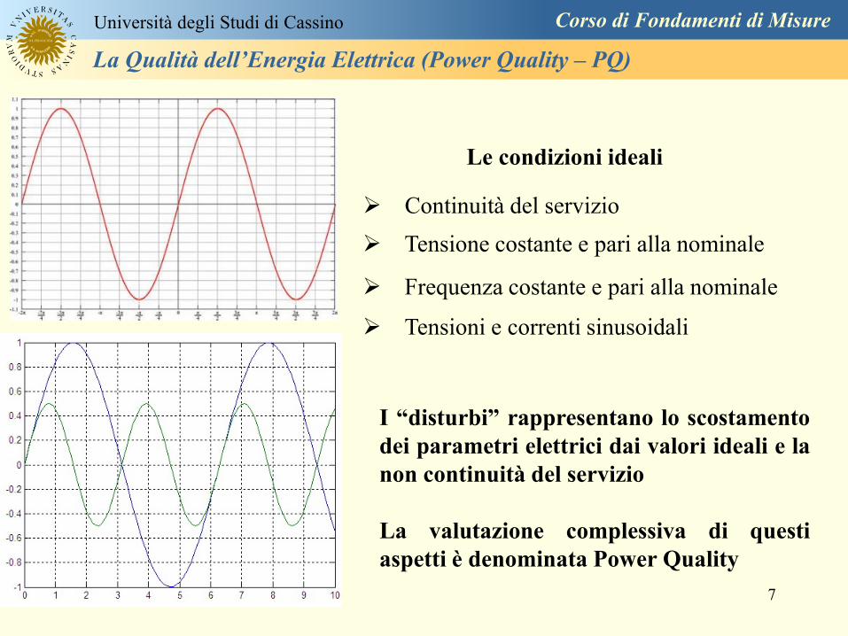
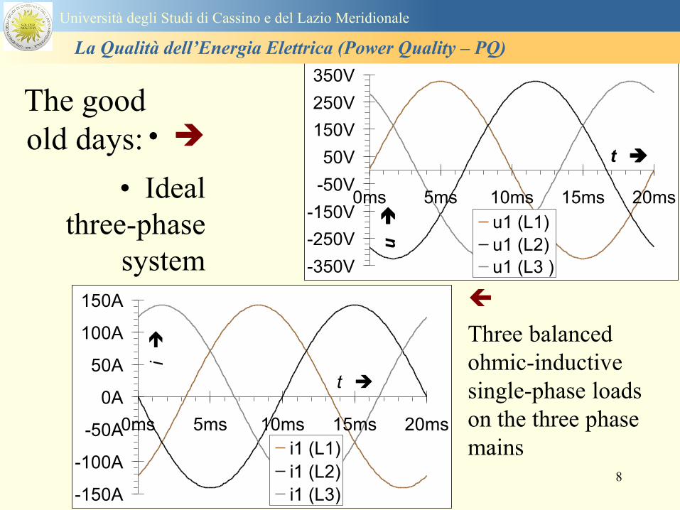
8
The good
old days bull
bull Ideal
three-phase
system
voltage
Three balanced
ohmic-inductive
single-phase loads
on the three phase
mains
-150A
-100A
-50A
0A
50A
100A
150A
0ms 5ms 10ms 15ms 20ms
t
i
i1 (L1)
i1 (L2)
i1 (L3)
-350V
-250V
-150V
-50V
50V
150V
250V
350V
0ms 5ms 10ms 15ms 20ms
t
u u1 (L1)
u1 (L2)
u1 (L3 )
Universitagrave degli Studi di Cassino e del Lazio Meridionale
La Qualitagrave dellrsquoEnergia Elettrica (Power Quality ndash PQ)
9
Distorsione armonica
Interruzioni del servizio
Abbassamenti di tensione e sovratensioni
Buchi di tensione
Transitori
Frequenza nominale della tensione fornita
Flicker - variazioni rapide della tensione
Squilibrio delle tensioni
Universitagrave degli Studi di Cassino e del Lazio Meridionale
La Qualitagrave dellrsquoEnergia Elettrica (Power Quality ndash PQ)
10
IEC 61000-2-22002 Electromagnetic compatibility (EMC) ndash Part 2-2 Environment ndash
Compatibility levels for low-frequency conducted disturbances and signalling in public
lowvoltage power supply systems
IEC 61000-2-4 Electromagnetic compatibility (EMC) ndash Part 2-4 Environment ndash
Compatibility levels in industrial plants for low-frequency conducted disturbances
IEC 61000-3-8 Electromagnetic compatibility (EMC) ndash Part 3 Limits ndash Section 8 Signalling
on low-voltage electrical installations ndash Emission levels frequency bands and electromagnetic
disturbance levels
IEC 61000-4-42004 Electromagnetic compatibility (EMC) ndash Part 4-4 Testing and
measurement techniques ndash Electrical fast transientburst immunity test
IEC 61000-4-72002 Electromagnetic compatibility (EMC) ndash Part 4-7 Testing and
measurement techniques ndash General guide on harmonics and interharmonics measurements
and instrumentation for power supply systems and equipment connected thereto
IEC 61000-4-302008 Electromagnetic compatibility (EMC) ndash Part 4-30 Testing and
measurement techniques ndash Power quality measurement methods
IEC 61000-4-15 Electromagnetic compatibility (EMC) ndash Part 4 Testing and measurement
techniques ndash Section 15 Flickermeter ndash Functional and design specifications
IEC 61180 (all parts) High-voltage test techniques for low voltage equipment
Normativa di riferimento
Universitagrave degli Studi di Cassino e del Lazio Meridionale
La Qualitagrave dellrsquoEnergia Elettrica (Power Quality ndash PQ)
11
IEC 61000 - 4 ndash 30 Norm
Seri 61000 Electromagnetic Compatibility
International Electrotechnical Commission
Part 4 Test and Measurement Tecniques
Section 30 PQ measurement methods
IEC 61000 - 4 ndash 7 Norm
Section 7 General guide on harmonics
and interharmonics measurements and
instrumentation for power supply
systems and equipment connected
thereto
Part 2 Environment ndashCompatibility levels
Seri 61000 Electromagnetic Compatibility
IEC International Electrotechnical Commission
Section xx details on the application sector
Part 3 Limits
Part 4 Test and Measurement Tecniques
Universitagrave degli Studi di Cassino e del Lazio Meridionale
La Qualitagrave dellrsquoEnergia Elettrica (Power Quality ndash PQ)
12
EN 501602010-07 Caratteristiche della tensione fornita dalle reti pubbliche di distribuzione
dellrsquoenergia elettrica
Descrive e specifica le caratteristiche principali della tensione ai terminali di
alimentazione di un utente della rete pubblica in bassa media e alta tensione in corrente
alternata in normali condizioni di esercizio Essa descrive i limiti o valori entro i quali le
caratteristiche della tensione possono essere attesi ai punti di alimentazione da reti elettriche
pubbliche europee e non descrive la situazione media sperimentata da un singolo utente di rete
Le caratteristiche della tensione fornite nella presente Norma non sono utilizzabili ai fini dei
limiti di EMC o di disturbi condotti nella rete pubblica Esse non sono utilizzabili ai fini di
prescrizioni nelle norme di prodotto o nelle norme per impianti
Normativa di riferimento
Universitagrave degli Studi di Cassino e del Lazio Meridionale
La Qualitagrave dellrsquoEnergia Elettrica (Power Quality ndash PQ)
13
Nel dettaglio la norma EN 50160 definisce i seguenti parametri
1 Frequenza nominale della tensione fornita
2 Ampiezza della tensione di alimentazione
3 Variazioni della tensione di alimentazione
4 Flicker - variazioni rapide della tensione
5 Buchi di tensione
6 Interruzioni della tensione di alimentazione
7 Squilibrio della tensione di alimentazione
8 Tensioni armoniche THD e fino al 25deg ordine
Universitagrave degli Studi di Cassino e del Lazio Meridionale
La Qualitagrave dellrsquoEnergia Elettrica (Power Quality ndash PQ)
14
Si specifica che qualora lrsquoazienda distributrice installi un registratore
della qualitagrave delle caratteristiche della tensione diverse dalle
interruzioni senza preavviso lunghe brevi e transitorie lo strumento
deve essere conforme alla norma tecnica EN 61000-4-30
Richiami nella delibera 042004
dellAUTORITA PER LENERGIA ELETTRICA E IL GAS
Il 30 gennaio 2004 con delibera 404 lrsquoautoritagrave dellrsquoenergia ha indicato tra i vari
argomenti trattati i criteri di misura delle qualitagrave della tensione
Nellrsquoarticolo 39 (pagina 29) viene indicato nel punto 391 e 2 che per la
registrazione di interruzioni senza preavviso lunghe brevi e transitorie occorre
utilizzare un registratore conforme alla CEI EN 50160 In questo caso lo strumento
registratore dice quando e per quanto si ha unrsquointerruzione del servizio ma a tutti gli
effetti NON EFFETTUA UNrsquoOSSERVAZIONE QUALITATIVA dei parametri
Universitagrave degli Studi di Cassino e del Lazio Meridionale
La Qualitagrave dellrsquoEnergia Elettrica (Power Quality ndash PQ)
15
Universitagrave degli Studi di Cassino e del Lazio Meridionale
La Qualitagrave dellrsquoEnergia Elettrica (Power Quality ndash PQ)
16
17
Universitagrave degli Studi di Cassino e del Lazio Meridionale
La Qualitagrave dellrsquoEnergia Elettrica (Power Quality ndash PQ)
CURVA DI TOLLERANZA AI DISTURBI
18
Caratteristiche dellrsquoalimentazione a bassa tensione
Universitagrave degli Studi di Cassino e del Lazio Meridionale
La Qualitagrave dellrsquoEnergia Elettrica (Power Quality ndash PQ)
19
Caratteristiche dellrsquoalimentazione a bassa tensione
Frequenza nominale
La frequenza nominale della tensione fornita deve essere di 50 Hz In condizioni normali
di esercizio il valore medio misurato nellrsquointervallo di 10 secondi deve essere
Per i sistemi con collegamento sincrono ad un sistema interconnesso
1 50 Hz plusmn 1 durante il 95 di un anno
2 50 Hz +4 - 6 durante il 100 di un anno
Per i sistemi senza collegamento sincrono ad un sistema interconnesso
1 50 Hz plusmn 2 durante il 95 di un anno
2 50 Hz plusmn 15 durante il 100 di un anno
Universitagrave degli Studi di Cassino e del Lazio Meridionale
La Qualitagrave dellrsquoEnergia Elettrica (Power Quality ndash PQ)
20
Caratteristiche dellrsquoalimentazione a bassa tensione
Universitagrave degli Studi di Cassino e del Lazio Meridionale
La Qualitagrave dellrsquoEnergia Elettrica (Power Quality ndash PQ)
21
Caratteristiche dellrsquoalimentazione a bassa tensione
Universitagrave degli Studi di Cassino e del Lazio Meridionale
La Qualitagrave dellrsquoEnergia Elettrica (Power Quality ndash PQ)
22
Variazioni della tensione di alimentazione (variazioni lente)
Le variazioni lente sono deviazioni ldquomedierdquo dal valore nominale dellrsquoampiezza della
tensione di consegna entro una fascia predefinita (per esempio del plusmn10) rispetto alla
tensione dichiarata
CAUSE variazione lenta dei carichi e dalla corrispondente azione di regolazione effettuata dai
variatori sotto carico dei trasformatori
Universitagrave degli Studi di Cassino e del Lazio Meridionale
La Qualitagrave dellrsquoEnergia Elettrica (Power Quality ndash PQ)
23
Variazioni della tensione di alimentazione (variazioni rapide)
Le variazioni rapide sono abbassamenti (o aumenti) bruschi di qualche percento della
tensione preesistente generalmente seguiti se abbassamenti da un ritorno (a rampa o di
altra forma) ad un valore intermedio tra quello preesistente e tra il minimo raggiunto
CAUSE commutazione dei carichi (partenza motori in particolare) funzionamento di carichi
con ciclo operativo particolarmente variabile e in qualche caso da manovre in rete (linee
trasformatori condensatori ecc)
Universitagrave degli Studi di Cassino e del Lazio Meridionale
La Qualitagrave dellrsquoEnergia Elettrica (Power Quality ndash PQ)
24
Flicker Il flicker egrave originato dalla fluttuazione della tensione Si definisce fluttuazione di tensione una
serie di variazioni rapide (uguali o diverse) della tensione
Fluttuazioni di tensione che presentano frequenze di modulazione del 50 Hz comprese tra 05 e
40 Hz danno origine al fenomeno del flicker (sfarfallio) ovvero della sensazione visiva
provocata dalle fluttuazioni dellrsquointensitagrave di illuminazione delle lampade
I suoi principali effetti sullrsquouomo possono essere mal di testa irritabilitagrave e fastidio agli occhi
Universitagrave degli Studi di Cassino e del Lazio Meridionale
La Qualitagrave dellrsquoEnergia Elettrica (Power Quality ndash PQ)
25
Universitagrave degli Studi di Cassino e del Lazio Meridionale
La Qualitagrave dellrsquoEnergia Elettrica (Power Quality ndash PQ)
26
La Qualitagrave dellrsquoEnergia Elettrica (Power Quality ndash PQ)
Universitagrave degli Studi di Cassino e del Lazio Meridionale
La Qualitagrave dellrsquoEnergia Elettrica (Power Quality ndash PQ)
27
Universitagrave degli Studi di Cassino e del Lazio Meridionale
La Qualitagrave dellrsquoEnergia Elettrica (Power Quality ndash PQ)
28
Universitagrave degli Studi di Cassino e del Lazio Meridionale
La Qualitagrave dellrsquoEnergia Elettrica (Power Quality ndash PQ)
29
Universitagrave degli Studi di Cassino e del Lazio Meridionale
La Qualitagrave dellrsquoEnergia Elettrica (Power Quality ndash PQ)
30
Universitagrave degli Studi di Cassino e del Lazio Meridionale
La Qualitagrave dellrsquoEnergia Elettrica (Power Quality ndash PQ)
31
Universitagrave degli Studi di Cassino e del Lazio Meridionale
La Qualitagrave dellrsquoEnergia Elettrica (Power Quality ndash PQ)
32
Buchi di tensione Riduzione temporanea della tensione in un punto della rete elettrica sotto una determinata
soglia Se durante un buco la tensione scende sotto una soglia di interruzione lrsquoevento egrave
considerato essere sia un buco che unrsquointerruzione
CAUSE I buchi di tensione sono generalmente dovuti a guasti che sopravvengono negli
impianti utilizzatori o nel sistema di distribuzione pubblico Possono dipendere anche variazioni
di carico lungo la linea
Universitagrave degli Studi di Cassino e del Lazio Meridionale
La Qualitagrave dellrsquoEnergia Elettrica (Power Quality ndash PQ)
33
Interruzioni della tensione di alimentazione Condizione in cui la tensione ad un terminale della rete egrave inferiore allrsquo1 della tensione
nominale per una durata fino a tre minuti (brevi) o maggiori di 3 minuti (lunghe)
Universitagrave degli Studi di Cassino e del Lazio Meridionale
La Qualitagrave dellrsquoEnergia Elettrica (Power Quality ndash PQ)
34
Sovratensioni temporanee alla frequenza di rete fra fasi e terra Le sovratensioni sono sopraelevazioni della tensione conseguenti a modificazioni dello
stato elettrico della rete elettrica
Universitagrave degli Studi di Cassino e del Lazio Meridionale
La Qualitagrave dellrsquoEnergia Elettrica (Power Quality ndash PQ)
35
Armoniche Le armoniche sono tensioni o correnti sinusoidali con frequenza pari ad un multiplo intero
(ordine) della frequenza fondamentale di funzionamento del sistema elettrico la cui
presenza determina una distorsione della forma drsquoonda della tensione di alimentazione
CAUSE In piccola parte dal sistema stesso (trasformatori etc) e per la maggior parte da
apparecchi utilizzatori carichi commutati elettronicamente raddrizzatori convertitori regolatori
in AC cicloconvertitori ecc carichi con caratteristiche non lineari apparecchiature a
saturazione magnetica lampade a scarica forni ad arco saldatrici ad arco trasformatori ecc
bull carichi inseriti e disinseriti da organi di manovra condensatori filtri e motori a induzione
Universitagrave degli Studi di Cassino e del Lazio Meridionale
La Qualitagrave dellrsquoEnergia Elettrica (Power Quality ndash PQ)
36
Armoniche di tensione e corrente ndash Problemi
Vi sono diversi ambiti causati dalle armoniche
bull problemi causati da armoniche di corrente
1048707 sovraccarico del neutro
1048707 aumento delle perdite nei trasformatori
1048707 interventi intempestivi degli interruttori automatici
1048707 aumento dellrsquoeffetto pelle
bull problemi causati da armoniche di tensione
1048707 deformazione della tensione
1048707 disturbi nella coppia dei motori ad induzione
1048707 rumore al passaggio per lo zero
bull problemi causati quando le armoniche di corrente raggiungono lrsquoalimentazione
Universitagrave degli Studi di Cassino e del Lazio Meridionale
La Qualitagrave dellrsquoEnergia Elettrica (Power Quality ndash PQ)
37
38
Universitagrave degli Studi di Cassino e del Lazio Meridionale
La Qualitagrave dellrsquoEnergia Elettrica (Power Quality ndash PQ)
39
Strumentazione ldquohand heldrdquo con display
Universitagrave degli Studi di Cassino e del Lazio Meridionale
La Qualitagrave dellrsquoEnergia Elettrica (Power Quality ndash PQ)
40
Strumentazione ldquohand heldrdquo con display
Universitagrave degli Studi di Cassino e del Lazio Meridionale
La Qualitagrave dellrsquoEnergia Elettrica (Power Quality ndash PQ)
41
Strumentazione da registrazione
Universitagrave degli Studi di Cassino e del Lazio Meridionale
La Qualitagrave dellrsquoEnergia Elettrica (Power Quality ndash PQ)
42
Schema di principio ndash 61000-4-30 copy IEC2008
The electrical quantity to be measured may be either directly accessible as is
generally the case in low-voltage systems or accessible via measurement
transducers
An instrument may include the whole measurement chain In this standard the
normative part does not consider the measurement transducers external to the
instrument and their associated uncertainty
Universitagrave degli Studi di Cassino e del Lazio Meridionale
La Qualitagrave dellrsquoEnergia Elettrica (Power Quality ndash PQ)
43
Universitagrave degli Studi di Cassino Corso di Fondamenti di Misure
La Qualitagrave dellrsquoEnergia Elettrica (Power Quality ndash PQ)
Classi dei metodi di misura - 61000-4-30 copy IEC2008
For each class measurement methods and appropriate performance requirements
are included
Sono definite tre classi A S e B
Class A
This class is used where precise measurements are necessary for example for contractual
applications that may require resolving disputes verifying compliance with standards etc
Any measurements of a parameter carried out with two different instruments complying with
the requirements of Class A when measuring the same signals will produce matching results
within the specified uncertainty for that parameter
Class S
This class is used for statistical applications such as surveys or power quality assessment
possibly with a limited subset of parameters Although it uses equivalent intervals of
measurement as class A the class S processing requirements are lower
Class B
This class is defined in order to avoid making many existing instruments designs obsolete
NOTE Class B methods are not recommended for new designs Readers are advised that Class B may be removed in a
future Edition of this standard
44
Classi dei metodi di misura - 61000-4-30 copy IEC2008
Measurement aggregation over time intervals
CLASS A
The basic measurement time interval for parameter magnitudes (supply voltage harmonics
interharmonics and unbalance) shall be a 10-cycle time interval for a 50 Hz power system
or 12-cycle time interval for a 60 Hz power system
The 1012-cycle measurement shall be re-synchronized at every RTC 10 min tick
The 1012-cycle values are then aggregated over 3 additional intervals
ndash 150180-cycle interval (150 cycles for 50 Hz nominal or 180 cycles for 60 Hz nominal)
ndash 10 min interval
ndash 2 h interval
CLASS S
Same time intervals as Class A
CLASS B
The manufacturer shall specify the number and duration of aggregation time intervals
Universitagrave degli Studi di Cassino e del Lazio Meridionale
La Qualitagrave dellrsquoEnergia Elettrica (Power Quality ndash PQ)
45
Universitagrave degli Studi di Cassino e del Lazio Meridionale
La Qualitagrave dellrsquoEnergia Elettrica (Power Quality ndash PQ)
46
Universitagrave degli Studi di Cassino e del Lazio Meridionale
La Qualitagrave dellrsquoEnergia Elettrica (Power Quality ndash PQ)
Class A
The 10-min aggregated value shall be tagged with the absolute time (for
example 01H1000) The time tag is the time at the conclusion of the 10-min
aggregation
The data for the 10-min time interval shall be aggregated from 1012-cycle time
intervals
Each 10-minute interval shall begin on a UTC 10-min tick The 10-min tick is
also used to re-synchronize the 1012-cycle intervals and the 150180-cycle
intervals
The final 1012-cycle interval(s) in a 10-min aggregation period will typically
overlap in time with the UTC 10-min clock tick Any overlapping 1012-cycle
interval (Overlap 1 in Figure 2) is included in the aggregation of the previous
10-min interval
47
Universitagrave degli Studi di Cassino e del Lazio Meridionale
La Qualitagrave dellrsquoEnergia Elettrica (Power Quality ndash PQ)
48
Universitagrave degli Studi di Cassino e del Lazio Meridionale
La Qualitagrave dellrsquoEnergia Elettrica (Power Quality ndash PQ)
49
Classi dei metodi di misura - 61000-4-30 copy IEC2008
Real time clock (RTC) uncertainty
Sono definite le specifiche per le 3 classi
Flagging concept
During a dip swell or interruption the measurement algorithm for other
parameters (for example frequency measurement) might produce an unreliable
value The flagging concept therefore avoids counting a single event more than
once in different parameters (for example counting a single dip as both a dip and a
frequency variation) and indicates that an aggregated value might be unreliable
Universitagrave degli Studi di Cassino e del Lazio Meridionale
La Qualitagrave dellrsquoEnergia Elettrica (Power Quality ndash PQ)
50
Classi dei metodi di misura - 61000-4-30 copy IEC2008
Power quality parameters - INDICES
Per ogni parametro viene suggerito il metodo di misura per le tre classi e
(soprattutto) le caratteristiche di precisione Per alcuni parametri rimanda a
specifiche norme (ad esempio Flicker e Armonicheinterarmoniche)
Esempio - Power frequency Class A
The frequency reading shall be obtained every 10 s As power frequency may not be exactly 50 Hz or 60
Hz within the 10 s time clock interval the number of cycles may not be an integer number The
fundamental frequency output is the ratio of the number of integral cycles counted during the 10 s time
clock interval divided by the cumulative duration of the integer cycles Before each assessment
harmonics and interharmonics shall be attenuated to minimize the effects of multiple zero crossings
The measurement time intervals shall be non-overlapping Individual cycles that overlap the 10 s time
clock are discarded Each 10 s interval shall begin on an absolute 10 s time clock with uncertainty as
defined in 46
Other techniques that provide equivalent results such as convolution are acceptable
Class S Same as class A
Class B The manufacturer shall specify the process used for frequency measurement
Universitagrave degli Studi di Cassino e del Lazio Meridionale
La Qualitagrave dellrsquoEnergia Elettrica (Power Quality ndash PQ)
51
Classi dei metodi di misura - 61000-4-30 copy IEC2008
Power quality parameters - INDICES
Per ogni parametro viene suggerito il metodo di misura per le tre classi e
(soprattutto) le caratteristiche di precisione Per alcuni parametri rimanda a
specifiche norme (ad esempio Flicker e Armonicheinterarmoniche)
Esempio - Power frequency
Measurement uncertainty and measuring range
ndash Class A
Under the conditions described in 61 the measurement uncertainty shall not exceed
plusmn10 mHz over the measuring ranges 425 Hz ~ 575 Hz 51 Hz ~ 69 Hz
ndash Class S
Under the conditions described in 61 the measurement uncertainty shall not exceed
plusmn50 mHz over the measuring ranges 425 Hz ~ 575 Hz 51 Hz ~ 69 Hz
ndash Class B
The manufacturer shall specify the uncertainty over the measuring ranges 425 Hz ~
575 Hz 51 Hz ~ 69 Hz
Universitagrave degli Studi di Cassino e del Lazio Meridionale
La Qualitagrave dellrsquoEnergia Elettrica (Power Quality ndash PQ)
52
Magnitude of the supply voltage
Measurement method
ndash Class A
The measurement shall be the rms value of the voltage magnitude over
a 10-cycle time interval for 50 Hz power system or 12-cycle time
interval for 60 Hz power system Every 1012-cycle interval shall be
contiguous and not overlapping with adjacent 1012-cycle intervals
except as shown as Overlap 1 in Figure 2
NOTE 1 This specific measurement method is used for quasi-stationary signals and is
not used for the detection and measurement of disturbances dips swells voltage
interruptions and transients
NOTE 2 The rms value includes by definition harmonics interharmonics mains
signalling etc
- Class S same as Class A
Universitagrave degli Studi di Cassino e del Lazio Meridionale
La Qualitagrave dellrsquoEnergia Elettrica (Power Quality ndash PQ)
53
Magnitude of the supply voltage
Measurement uncertainty and measuring range
ndash Class A
Under the conditions described in Clause 6 the measurement uncertainty
shall not exceed plusmn01 of Udin over the range of 10 ~ 150 of Udin
ndash Class S
Under the conditions described in Clause 6 the measurement uncertainty
shall not exceed plusmn05 of Udin over the range of 20 ~ 120 of Udin
Universitagrave degli Studi di Cassino e del Lazio Meridionale
La Qualitagrave dellrsquoEnergia Elettrica (Power Quality ndash PQ)
54
Supply voltage dips and swells
Measurement method
ndash Class A
The basic measurement Urms of a voltage dip and swell shall be the
Urms(frac12) on each measurement channel (see Clause 322)
The cycle duration for Urms(frac12) depends on the frequency The
frequency might be determined by the last non-flagged power frequency
measurement (see Clause 47 and Clause 51) or by any other method
that yields the uncertainty requirements of Clause 6
NOTE 1 The Urms(frac12) value includes by definition harmonics interharmonics mains
signalling voltage etc
NOTE 2 It is important to avoid loss of data when dips and swells occur in a rapid
sequence (for example three events in one second with up to one minute between
sequences may occur when a recloser operates into a sustained fault) If during a rapid
burst the dipswell event characteristics cannot be recorded then a count of events may
be useful
Universitagrave degli Studi di Cassino e del Lazio Meridionale
La Qualitagrave dellrsquoEnergia Elettrica (Power Quality ndash PQ)
55
Supply voltage dips and swells
Detection and evaluation of a voltage dip
Voltage dip detection
The dip threshold is a percentage of either Udin or the sliding voltage
reference Usr (see 525 544) The user shall declare the reference
voltage in use
NOTE ndash On single-phase systems a voltage dip begins when the Urms voltage falls
below the dip threshold and ends when the Urms voltage is equal to or above the dip
threshold plus the hysteresis voltage
ndash On polyphase systems a dip begins when the Urms voltage of one or more channels is
below the dip threshold and ends when the Urms voltage on all measured channels is
equal to or above the dip threshold plus the hysteresis voltage
The dip threshold and the hysteresis voltage are both set by the user according to the
use
Universitagrave degli Studi di Cassino e del Lazio Meridionale
La Qualitagrave dellrsquoEnergia Elettrica (Power Quality ndash PQ)
56
Calculation of a sliding reference voltage
The sliding reference voltage implementation is optional not mandatory
If a sliding reference is chosen for voltage dip or swell detection this
shall be calculated using a first-order filter with a 1-min time constant
This filter is given by
Usr(n) = 09967 times Usr(nndash1) + 00033 times U(1012)rms
where
Usr(n) is the present value of the sliding reference voltage
Usr(nndash1) is the previous value of the sliding reference voltage and
U(1012)rms is the most recent 1012-cycle rms value
When the measurement is started the initial value of the sliding reference voltage is set
to the declared input voltage The sliding reference voltage is updated every 1012-
cycles If a 1012-cycle value is flagged the sliding reference voltage is not updated
and the previous value is used
Universitagrave degli Studi di Cassino e del Lazio Meridionale
La Qualitagrave dellrsquoEnergia Elettrica (Power Quality ndash PQ)
57
Supply voltage dips and swells
Voltage dip evaluation
A voltage dip is characterized by a pair of data either residual voltage
(Ures) or depth and duration
ndash the residual voltage of a voltage dip is the lowest Urms(frac12) value
measured on any channel during the dip
ndash the depth is the difference between the reference voltage (either Udin
or Usr) and the residual voltage It is generally expressed in percentage
of the reference voltage
NOTE 1 During the dip it may be useful to also record the lowest Urms(frac12) on each
channel in addition to the residual voltage of the dip The duration spent below the dip
threshold on each channel may also be useful
Universitagrave degli Studi di Cassino e del Lazio Meridionale
La Qualitagrave dellrsquoEnergia Elettrica (Power Quality ndash PQ)
58
Supply voltage dips and swells
Voltage dip evaluation
NOTE 2 If voltage waveforms are recorded before during and after a
dip useful information about phase angle changes may be available in
the recorded data
The start time of a dip shall be time stamped with the time of the start of
the Urms of the channel that initiated the event and the end time of the
dip shall be the time stamped with the time of the end of the Urms that
ended the event as defined by the threshold plus the hysteresis
The duration of a voltage dip is the time difference between the start
time and the end time of the voltage dip
Universitagrave degli Studi di Cassino e del Lazio Meridionale
La Qualitagrave dellrsquoEnergia Elettrica (Power Quality ndash PQ)
59
Supply voltage dips and swells
Residual voltage and swell voltage magnitude measurement
uncertainty
ndash Class A
The measurement uncertainty shall not exceed plusmn02 of Udin
ndash Class S
The measurement uncertainty shall not exceed plusmn10 of Udin
Universitagrave degli Studi di Cassino e del Lazio Meridionale
La Qualitagrave dellrsquoEnergia Elettrica (Power Quality ndash PQ)
60
Schema di principio ndash 61000-4-7 copy IEC2002
Universitagrave degli Studi di Cassino e del Lazio Meridionale
La Qualitagrave dellrsquoEnergia Elettrica (Power Quality ndash PQ)
61
Universitagrave degli Studi di Cassino e del Lazio Meridionale
La Qualitagrave dellrsquoEnergia Elettrica (Power Quality ndash PQ)
62
Universitagrave degli Studi di Cassino e del Lazio Meridionale
La Qualitagrave dellrsquoEnergia Elettrica (Power Quality ndash PQ)
63
Inter-Armoniche Le inter-armoniche sono tensioni o correnti sinusoidali con frequenza diversa da un
multiplo intero della fondamentale la cui presenza determina una distorsione
(modulazione) della forma donda della tensione di alimentazione
CAUSE dai carichi che assorbono correnti inter-armoniche
- carichi commutati elettronicamente convertitori cascata subsincrona cicloconvertitori regolatori con
controllo a pacchetti di cicli ecc
- carichi con caratteristiche non lineari eo non stazionarie forni ad arco saldatrici ad arco ecc
Universitagrave degli Studi di Cassino e del Lazio Meridionale
La Qualitagrave dellrsquoEnergia Elettrica (Power Quality ndash PQ)
64
Universitagrave degli Studi di Cassino e del Lazio Meridionale
La Qualitagrave dellrsquoEnergia Elettrica (Power Quality ndash PQ)
Un porsquo di esempi e
consigli praticihellip
65
0V
50V
100V
150V
200V
250V
300V
350V
0ms 5ms 10ms 15ms 20ms
t
u
0A
1A
2A
3A
i
0V
50V
100V
150V
200V
250V
300V
350V
0ms 5ms 10ms 15ms 20ms
t
u
0A
1A
2A
3A
i
0V
50V
100V
150V
200V
250V
300V
350V
0ms 5ms 10ms 15ms 20ms
t
u
0A
1A
2A
3A
i
gleichgerichtete
Netzspannung
Kondensator-
spannung
gleichgerichteter
Netzstrom
The situation
today
bull Computed current and voltage profiles when a
230 V 58 W fluorescent lamp with an old-style
electronic ballast is driven on the phase wire of
a typical power distribution system
System voltage 230 V
System frequency 50 Hz
Source resistance 500 mW
Longitudinal induction 904 microH
System impedance 575 mW
Mean dc current 180 mA
Smoothing capacitance220 microF
66
And what about electronic ballasts that are rated over 25W
Introduce electronic power factor correction (PFC)
0V
20V
40V
60V
80V
100V
120V
140V
160V
180V
200V
220V
0deg 15deg 30deg 45deg
u
00A
03A
06A
09A
12A
i
67
Though todayrsquos ballasts are better if
rated gt25 W bull Only
the
small
ones
continu
e to
pollute
just like
PCs
TV sets
do
68
This leads to a number of
previously unknown effects bull 1 Deformed voltage curves
bull 2 Huge inrush current peaks
bull 3 Instrument dependent measured parameters
bull 4 Increased loading of phase conductors
bull 5 Loading and overloading of the neutral conductor
bull 6 Overheating and start-up problems of induction motors
bull 7 Additional stray losses in transformers
bull 8 Repercussions of generators upon the mains
bull 9 Influence of capacitors repercussions upon the mains
and four additional complications in TN-C systems
10 Stray currents in equipotential bonding system magnetic fields
11 Contamination of data streams by stray currents
12 Stray currents in the earthing system corrosion damage
13 Lightning currents in devices and equipment
69
1 Deformed voltage curves
bull in theory
-350V
-300V
-250V
-200V
-150V
-100V
-50V
0V
50V
100V
150V
200V
250V
300V
350V
0 5 10 15 20
t ms
u
System voltage profile when driving
a single-phase load comprising
twenty 58 W energy-saver lamps in
parallel on a typical 230 V power
system
70
and in practice
bull An actual
current profile
bull
bull and
bull a voltage profile
bull
bull recorded in a large storage
dispatch and administrative
building
71
at home or in industrial environments
bull
bull Television 40
W
bull 200 Vdiv 2
Adiv
bull 5 msdiv
Harmonic
spectrum
Frequency
converter
50 Adiv
Phase currents
I1=I2=I3=160 A
IN=295 A
5 msdiv
72
Every periodic waveform can be written
as the infinite sum of sinusoidal waves
-175
-150
-125
-100
-75
-50
-25
0
25
50
75
100
125
150
175
0 5 10 15 20
t ms
i
mA
itot
i1
Synthesis of a triangular current profile 100mA
Content fundamental I = 99 mA Isup2 = 9855 mAsup2
Sum of squares Isup2 = 9855 mAsup2
Root of sum = RMS value I = 99 mA
-175
-150
-125
-100
-75
-50
-25
0
25
50
75
100
125
150
175
0 5 10 15 20
t ms
i
mA
itot
i1
i3
Synthesis of a triangular current profile 100mA
Content fundamental I = 99 mA Isup2 = 9855 mAsup2
Cont 3 rd harmonic I = -11 mA Isup2 = 122 mAsup2
Sum of squares Isup2 = 9977 mAsup2
Root of sum = RMS value I = 100 mA
-175
-150
-125
-100
-75
-50
-25
0
25
50
75
100
125
150
175
0 5 10 15 20
t ms
i
mA
itot
i1
i3
i5
Synthesis of a triangular current profile 100mA
Content fundamental I = 99 mA Isup2 = 9855 mAsup2
Cont 3 rd harmonic I = -11 mA Isup2 = 122 mAsup2
Cont 5 th harmonic I = 4 mA Isup2 = 16 mAsup2
Sum of squares Isup2 = 9993 mAsup2
Root of sum = RMS value I = 100 mA
-175
-150
-125
-100
-75
-50
-25
0
25
50
75
100
125
150
175
0 5 10 15 20
t ms
i
mA
itot
i1
i3
i5
i7
Synthesis of a triangular current profile 100mA
Content fundamental I = 99 mA Isup2 = 9855 mAsup2
Cont 3 rd harmonic I = -11 mA Isup2 = 122 mAsup2
Cont 5 th harmonic I = 4 mA Isup2 = 16 mAsup2
Cont 7 th harmonic I = -2 mA Isup2 = 4 mAsup2
Sum of squares Isup2 = 9997 mAsup2
Root of sum = RMS value I = 100 mA
-175
-150
-125
-100
-75
-50
-25
0
25
50
75
100
125
150
175
0 5 10 15 20
t ms
i
mA
itot i1
i3 i5
i7 i9
Synthesis of a triangular current profile 100mA
Content fundamental I = 99 mA Isup2 = 9855 mAsup2
Cont 3 rd harmonic I = -11 mA Isup2 = 122 mAsup2
Cont 5 th harmonic I = 4 mA Isup2 = 16 mAsup2
Cont 7 th harmonic I = -2 mA Isup2 = 4 mAsup2
Cont 9 th harmonic I = 1 mA Isup2 = 2 mAsup2
Sum of squares Isup2 = 9998 mAsup2
Root of sum = RMS value I = 100 mA
-175
-150
-125
-100
-75
-50
-25
0
25
50
75
100
125
150
175
0 5 10 15 20
t ms
i
mA
itot i1
i3 i5
i7 i9
i11
Synthesis of a triangular current profile 100mA
Content fundamental I = 99 mA Isup2 = 9855 mAsup2
Cont 3 rd harmonic I = -11 mA Isup2 = 122 mAsup2
Cont 5 th harmonic I = 4 mA Isup2 = 16 mAsup2
Cont 7 th harmonic I = -2 mA Isup2 = 4 mAsup2
Cont 9 th harmonic I = 1 mA Isup2 = 2 mAsup2
Cont 11 th harmonic I = -1 mA Isup2 = 1 mAsup2
Sum of squares Isup2 = 9999 mAsup2
Root of sum = RMS value I = 100 mA
-175
-150
-125
-100
-75
-50
-25
0
25
50
75
100
125
150
175
0 5 10 15 20
t ms
i
mA
itot i1
i3 i5
i7 i9
i11 i13
Synthesis of a triangular current profile 100mA
Content fundamental I = 99 mA Isup2 = 9855 mAsup2
Cont 3 rd harmonic I = -11 mA Isup2 = 122 mAsup2
Cont 5 th harmonic I = 4 mA Isup2 = 16 mAsup2
Cont 7 th harmonic I = -2 mA Isup2 = 4 mAsup2
Cont 9 th harmonic I = 1 mA Isup2 = 2 mAsup2
Cont 11 th harmonic I = -1 mA Isup2 = 1 mAsup2
Cont 13 th harmonic I = 1 mA Isup2 = 0 mAsup2
Sum of squares Isup2 = 9999 mAsup2
Root of sum = RMS value I = 100 mA
-175
-150
-125
-100
-75
-50
-25
0
25
50
75
100
125
150
175
0 5 10 15 20
t ms
i
mA
itot i1
i3 i5
i7 i9
i11 i13
i15
Synthesis of a triangular current profile 100mA
Content fundamental I = 99 mA Isup2 = 9855 mAsup2
Cont 3 rd harmonic I = -11 mA Isup2 = 122 mAsup2
Cont 5 th harmonic I = 4 mA Isup2 = 16 mAsup2
Cont 7 th harmonic I = -2 mA Isup2 = 4 mAsup2
Cont 9 th harmonic I = 1 mA Isup2 = 2 mAsup2
Cont 11 th harmonic I = -1 mA Isup2 = 1 mAsup2
Cont 13 th harmonic I = 1 mA Isup2 = 0 mAsup2
Cont 15 th harmonic I = 0 mA Isup2 = 0 mAsup2
Sum of squares Isup2 = 10000 mAsup2
Root of sum = RMS value I = 100 mA
-175
-150
-125
-100
-75
-50
-25
0
25
50
75
100
125
150
175
0 5 10 15 20
t ms
i
mA
itot i1
i3 i5
i7 i9
i11 i13
i15 i17
Synthesis of a triangular current profile 100mA
Content fundamental I = 99 mA Isup2 = 9855 mAsup2
Cont 3 rd harmonic I = -11 mA Isup2 = 122 mAsup2
Cont 5 th harmonic I = 4 mA Isup2 = 16 mAsup2
Cont 7 th harmonic I = -2 mA Isup2 = 4 mAsup2
Cont 9 th harmonic I = 1 mA Isup2 = 2 mAsup2
Cont 11 th harmonic I = -1 mA Isup2 = 1 mAsup2
Cont 13 th harmonic I = 1 mA Isup2 = 0 mAsup2
Cont 15 th harmonic I = 0 mA Isup2 = 0 mAsup2
Cont 17 th harmonic I = 0 mA Isup2 = 0 mAsup2
Sum of squares Isup2 = 10000 mAsup2
Root of sum = RMS value I = 100 mA
73
whose frequencies called harmonics are
integer multiples of the fundamental frequency
-175
-150
-125
-100
-75
-50
-25
0
25
50
75
100
125
150
175
0 5 10 15 20
t ms
i
mA
itot
i1
Synthesis of a rectangular current profile 100mA
Content fundamental I = 90 mA Isup2 = 8106 mAsup2
Sum of squares Isup2 = 8106 mAsup2
Root of sum = RMS value I = 90 mA
-175
-150
-125
-100
-75
-50
-25
0
25
50
75
100
125
150
175
0 5 10 15 20
t ms
i
mA
itot
i1
i3
Synthesis of a rectangular current profile 100mA
Content fundamental I = 90 mA Isup2 = 8106 mAsup2
Cont 3 rd harmonic I = 30 mA Isup2 = 901 mAsup2
Sum of squares Isup2 = 9006 mAsup2
Root of sum = RMS value I = 95 mA
-175
-150
-125
-100
-75
-50
-25
0
25
50
75
100
125
150
175
0 5 10 15 20
t ms
i
mA
itot
i1
i3
i5
Synthesis of a rectangular current profile 100mA
Content fundamental I = 90 mA Isup2 = 8106 mAsup2
Cont 3 rd harmonic I = 30 mA Isup2 = 901 mAsup2
Cont 5 th harmonic I = 18 mA Isup2 = 324 mAsup2
Sum of squares Isup2 = 9331 mAsup2
Root of sum = RMS value I = 97 mA
-175
-150
-125
-100
-75
-50
-25
0
25
50
75
100
125
150
175
0 5 10 15 20
t ms
i
mA
itot
i1
i3
i5
i7
Synthesis of a rectangular current profile 100mA
Content fundamental I = 90 mA Isup2 = 8106 mAsup2
Cont 3 rd harmonic I = 30 mA Isup2 = 901 mAsup2
Cont 5 th harmonic I = 18 mA Isup2 = 324 mAsup2
Cont 7 th harmonic I = 13 mA Isup2 = 165 mAsup2
Sum of squares Isup2 = 9496 mAsup2
Root of sum = RMS value I = 97 mA
-175
-150
-125
-100
-75
-50
-25
0
25
50
75
100
125
150
175
0 5 10 15 20
t ms
i
mA
itot i1
i3 i5
i7 i9
Synthesis of a rectangular current profile 100mA
Content fundamental I = 90 mA Isup2 = 8106 mAsup2
Cont 3 rd harmonic I = 30 mA Isup2 = 901 mAsup2
Cont 5 th harmonic I = 18 mA Isup2 = 324 mAsup2
Cont 7 th harmonic I = 13 mA Isup2 = 165 mAsup2
Cont 9 th harmonic I = 10 mA Isup2 = 100 mAsup2
Sum of squares Isup2 = 9596 mAsup2
Root of sum = RMS value I = 98 mA
-175
-150
-125
-100
-75
-50
-25
0
25
50
75
100
125
150
175
0 5 10 15 20
t ms
i
mA
itot i1
i3 i5
i7 i9
i11
Synthesis of a rectangular current profile 100mA
Content fundamental I = 90 mA Isup2 = 8106 mAsup2
Cont 3 rd harmonic I = 30 mA Isup2 = 901 mAsup2
Cont 5 th harmonic I = 18 mA Isup2 = 324 mAsup2
Cont 7 th harmonic I = 13 mA Isup2 = 165 mAsup2
Cont 9 th harmonic I = 10 mA Isup2 = 100 mAsup2
Cont 11 th harmonic I = 8 mA Isup2 = 67 mAsup2
Sum of squares Isup2 = 9663 mAsup2
Root of sum = RMS value I = 98 mA
-175
-150
-125
-100
-75
-50
-25
0
25
50
75
100
125
150
175
0 5 10 15 20
t ms
i
mA
itot i1
i3 i5
i7 i9
i11 i13
Synthesis of a rectangular current profile 100mA
Content fundamental I = 90 mA Isup2 = 8106 mAsup2
Cont 3 rd harmonic I = 30 mA Isup2 = 901 mAsup2
Cont 5 th harmonic I = 18 mA Isup2 = 324 mAsup2
Cont 7 th harmonic I = 13 mA Isup2 = 165 mAsup2
Cont 9 th harmonic I = 10 mA Isup2 = 100 mAsup2
Cont 11 th harmonic I = 8 mA Isup2 = 67 mAsup2
Cont 13 th harmonic I = 7 mA Isup2 = 48 mAsup2
Sum of squares Isup2 = 9711 mAsup2
Root of sum = RMS value I = 99 mA
-175
-150
-125
-100
-75
-50
-25
0
25
50
75
100
125
150
175
0 5 10 15 20
t ms
i
mA
itot i1
i3 i5
i7 i9
i11 i13
i15
Synthesis of a rectangular current profile 100mA
Content fundamental I = 90 mA Isup2 = 8106 mAsup2
Cont 3 rd harmonic I = 30 mA Isup2 = 901 mAsup2
Cont 5 th harmonic I = 18 mA Isup2 = 324 mAsup2
Cont 7 th harmonic I = 13 mA Isup2 = 165 mAsup2
Cont 9 th harmonic I = 10 mA Isup2 = 100 mAsup2
Cont 11 th harmonic I = 8 mA Isup2 = 67 mAsup2
Cont 13 th harmonic I = 7 mA Isup2 = 48 mAsup2
Cont 15 th harmonic I = 6 mA Isup2 = 36 mAsup2
Sum of squares Isup2 = 9747 mAsup2
Root of sum = RMS value I = 99 mA
-175
-150
-125
-100
-75
-50
-25
0
25
50
75
100
125
150
175
0 5 10 15 20
t ms
i
mA
itot i1
i3 i5
i7 i9
i11 i13
i15 i17
Synthesis of a rectangular current profile 100mA
Content fundamental I = 90 mA Isup2 = 8106 mAsup2
Cont 3 rd harmonic I = 30 mA Isup2 = 901 mAsup2
Cont 5 th harmonic I = 18 mA Isup2 = 324 mAsup2
Cont 7 th harmonic I = 13 mA Isup2 = 165 mAsup2
Cont 9 th harmonic I = 10 mA Isup2 = 100 mAsup2
Cont 11 th harmonic I = 8 mA Isup2 = 67 mAsup2
Cont 13 th harmonic I = 7 mA Isup2 = 48 mAsup2
Cont 15 th harmonic I = 6 mA Isup2 = 36 mAsup2
Cont 17 th harmonic I = 5 mA Isup2 = 28 mAsup2
Sum of squares Isup2 = 9775 mAsup2
Root of sum = RMS value I = 99 mA
74
Even far better simulations are
available free of charge at
bull wwwpowerstandardscomMcEachern
75
-4A
-3A
-2A
-1A
0A
1A
2A
3A
4A
0ms 5ms 10ms 15ms 20ms
t
i
-4A
-3A
-2A
-1A
0A
1A
2A
3A
4A
0ms 5ms 10ms 15ms 20ms
t
i
Applying the Fourier
analysis to a real PC
current does not work
directly
bull
bull but it can be
modelled by a similar
triangular curve in
which not all of the
higher harmonics
have been included
Triangular current profile of
the same amplitude and a
pulse duty cycle of 17
Input current of a PC
with monitor
76
Analysis of the model triangular waveform
-400
-350
-300
-250
-200
-150
-100
-50
0
50
100
150
200
250
300
350
400
0 5 10 15 20
t ms
iI
itot(t) L1 [A] i1(t) L1 [A]
i3(t) L1 [A] i5(t) L1 [A]
i7(t) L1 [A] i9(t) L1 [A]
i11(t) L1 [A] i13(t) L1 [A]
i15(t) L1 [A] i17(t) L1 [A]
77
M3
Harmonics
Energy
(active
power)
L1
L2
L3
N
PE
Important
bull Harmonics are created within the loads
themselves and can flow ldquoupstreamrdquo to
contaminate the power system
78
-6A
-5A
-4A
-3A
-2A
-1A
0A
1A
2A
3A
4A
5A
6A
0ms 5ms 10ms 15ms 20ms
t
i
Squared values
Without
Fundamental 502 mA 251986 mAsup2 the fundamental
3rd harmonic -479 mA 229000 mAsup2 229000 mAsup2
5th harmonic 434 mA 188595 mAsup2 188595 mAsup2
7th harmonic -374 mA 139903 mAsup2 139903 mAsup2
9th harmonic 304 mA 92527 mAsup2 92527 mAsup2
11th harmonic -232 mA 53671 mAsup2 53671 mAsup2
13th harmonic 163 mA 26600 mAsup2 26600 mAsup2
15th harmonic -104 mA 10780 mAsup2 10780 mAsup2
17th harmonic 57 mA 3299 mAsup2 3299 mAsup2
Sum of the squares 996362 mAsup2 744377 mAsup2
Root thereof 998 mAeff THD = 863 mA
What actually is THD Example shown here triangular current
profile with an rms current of 1000 mA
and a pulse duty cycle of 17
THDr (root mean square) = 863mA1000mA = 86
THDf (fundamental) = 863mA502mA = 172
79
Effect on phase-to-neutral
and phase-to-phase voltages
bull Recorded
on June
30 2002
230 p
m
bull What
was the
matter
then
bull The
soccer
final
Germany
vs
Brazil
80
The triple-N harmonics drive
a circulating current in the
delta winding of a distribution
transformer
bull but the
bull voltage harmonics
propagate into the next
low-voltage power
distribution system
81 0V
50V
100V
150V
200V
250V
300V
350V
400V
450V
500V
550V
0 10 20 30 40 50
t ms
u
0A
10A
20A
30A
40A
50A
60A
70A
80A
90A
100A
110A
120A
130A
140A
150A
i
Switching on just as supply voltage passes through zero
0V
50V
100V
150V
200V
250V
300V
350V
400V
450V
500V
550V
0 10 20 30 40 50
t ms
u
0A
10A
20A
30A
40A
50A
60A
70A
80A
90A
100A
110A
120A
130A
140A
150A
i
Switching on just as supply voltage is at its peak
2 Huge inrush current peaks
ndash in theory
82
and in practice
bull Inrush current of a
compact energy-
saver lamp and its
effect on the system
voltage (recorded at
the Technical
University of
Budapest)
bull
83
enables us to infer what
happens when run by a
normal three-phase supply
The same fluorescent lamp
with a magnetic ballast
bull The behaviour measured
when connected to
a dc supply
bull
Behaviour of a 58 W fluorescent lamp connected to a dc
supply
0
20
40
60
80
100
120
140
160
180
200
0 200 400 600 800 1000 1200
i mA
u
V
Measurement
Behaviour of a 58 W fluorescent lamp connected to a dc
supply
0
20
40
60
80
100
120
140
160
180
200
0 200 400 600 800 1000 1200
i mA
u
V
MeasurementCalculation
-350
-300
-250
-200
-150
-100
-50
0
50
100
150
200
250
300
350
0 5 10 15 20
t ms
u
V
-10
-08
-06
-04
-02
00
02
04
06
08
10
i
A
Systems voltage
Current
-350
-300
-250
-200
-150
-100
-50
0
50
100
150
200
250
300
350
0 5 10 15 20
t ms
u
V
-10
-08
-06
-04
-02
00
02
04
06
08
10
i
A
Systems voltage
Lamp voltage
Current
84
Warning ldquoCompensationrdquo is not
always what you think it is
bull Distinguish
between
bull Reactive
power
compensatio
n
aka power
factor
correction
Remedial
measure
Parallel (or
sometimes series)
compensation
using capacitors
Filter circuits
tuned to the
individual harmonic
frequencies
Harmonic
compensation
85
5 (Over)loading the neutral conductor
bull Magnetic ballast Old-style electronic ballast
-25A
-20A
-15A
-10A
-05A
00A
05A
10A
15A
20A
25A
0 5 10 15 20
t ms i
i(t) N
-25A
-20A
-15A
-10A
-05A
00A
05A
10A
15A
20A
25A
0 5 10 15 20
t ms
i
i(t) N
-25A
-20A
-15A
-10A
-05A
00A
05A
10A
15A
20A
25A
0 5 10 15 20
t ms
i
i(t) L1 i(t) L2 i(t) L3
-25A
-20A
-15A
-10A
-05A
00A
05A
10A
15A
20A
25A
0 5 10 15 20
t ms
i
i(t) L1
i(t) L2
i(t) L3
86
Adding the 3rd
harmonics
in the
neutral
wire
-150-100-50
050
100150
0deg 30deg 60deg 90deg 120deg 150deg 180deg 210deg 240deg 270deg 300deg 330deg 360deg
L1
-150-100-50
050
100150
0deg 30deg 60deg 90deg 120deg 150deg 180deg 210deg 240deg 270deg 300deg 330deg 360deg
L2
-150-100-50
050
100150
0deg 30deg 60deg 90deg 120deg 150deg 180deg 210deg 240deg 270deg 300deg 330deg 360deg
L3
-450-400-350-300-250-200-150-100-50
050
100150200250300350400450
0deg 30deg 60deg 90deg 120deg 150deg 180deg 210deg 240deg 270deg 300deg 330deg 360deg
f
iicirc
N
Physics dictates
that at any
moment in time
the phase and
neutral currents
must sum to zero
87
Effect on a three-phase ac motor
appears almost identical
bull The same motor is being
driven
simultaneously in
these three modes
homopolar system
zero-sequence system
direct system
positive-sequence system
inverse system
negative-sequence system
88
The transformer
influences the load
89
but the load also effects
the transformer
Total transformer loss is
2
)()(
nom
nomCunomFeLossI
IPPP
While total transformer loss really is
2
)(
2
)(
2
)(
nomnom
nomad
nom
nomCu
nom
nomFeLossI
I
f
fP
I
IP
U
UPP
90
6 ldquosupplementaryrdquo additional losses
in transformers
can be calculated rapidly
using the following two
simple formulae 50
2
2
1
2
11
Nn
n
nqh
I
In
I
I
e
eK
50
1
2
1
1
50
1
2
Nn
n
nNn
n
nI
IIII
where
Oh well
perhaps a practical
example is clearer
1000 compact 11W
(15VA) energy-saver
lamps powered by a
15kVA transformer
uSC=4 Pa=01PCu
Harmonics of an Osram Dulux 11W
CFL and a serial impedance of
R =291Ω amp X L=113Ω
U U sup2 I L I Lsup2 P aP Cu
n V Vsup2 mA mAsup2
1 2302 529920 485 23523 56
3 83 689 371 13764 295
5 107 1145 203 4121 245
7 43 185 53 281 33
9 11 12 30 90 17
11 23 53 38 144 42
13 10 10 15 23 09
15 06 04 15 23 12
17 11 12 15 23 15
19 05 03 09 08 07
21 05 03 13 17 18
23 06 04 08 06 08
25 04 02 06 04 05
27 06 04 08 06 11
29 04 02 05 03 05
31 03 01 05 03 06
33 03 01 05 03 06
35 03 01 04 02 05
37 03 01 04 02 05
39 03 01 03 01 03
41 01 00 03 01 04
43 02 00 02 00 02
45 01 00 02 00 02
47 01 00 02 00 02
49 01 00 01 00 01
51 01 00 01 00 01
P aP Cu = 814814
etc
etc
91
Harmonics measurement on an
Osram Dulux 11W compact
fluorescent lamp
U U sup2 I L I Lsup2 P addP Cu
n V Vsup2 mA mAsup2
1 2327 541493 489 23912 37
3 06 04 391 15288 215
5 44 194 264 6970 273
7 23 53 200 4000 307
9 01 00 192 3686 467
11 01 00 166 2756 522
13 01 00 127 1613 427
15 01 00 110 1210 426
17 01 00 102 1040 471
19 01 00 87 757 428
21 01 00 77 593 409
23 01 00 73 533 441
25 01 00 61 372 364
27 01 00 49 240 274
29 01 00 42 176 232
31 01 00 36 130 195
33 01 00 30 90 153
35 01 00 33 109 209
37 01 00 31 96 206
39 01 00 25 63 149
41 01 00 25 63 164
43 01 00 25 63 181
45 01 00 19 36 114
47 01 00 18 32 112
49 01 00 19 36 136
51 01 00 16 26 104
P aP Cu = 7017
To some extent
the transformer
protects itself
bull Always remember to
consider it
bull If the influence of the
transformer upon the load
did not exist then the
influence of the load upon
the transformer would be
nearly 9 times as high
7017
etc
etc
92
Rule of thumb Select transformers 35
larger than specification by apparent
power would require
bull This suffices to err
on the safe side
even in the worst
case and can
hardly ever be
wrong since
maximum
efficiency always
lies between 25
and 50 of rated
load
Efficiency of a 1 MVA transformer plotted against loading
985
986
987
988
989
990
991
992
993
994
0 25 50 75 100 125
Relative load h
Design with max Cu loss and min Fe loss
Design with min Cu loss and max Fe loss
1 MVA oil transformer according to HD 428
93
Measured response of an 11 W
fluorescent lamp operated with a
magnetic ballast
94
We are
dealing with
a complex
problem
bull These
effects
are not
isolated
but are
mutuall
y inter-
depende
nt
Effects 2 3 and 5 can be demonstrated
on DKIrsquos display panel
95
A conventional approximately resistive-
inductive load
mA
N L1 L2 L3
Two conventional approximately
resistive-inductive loads Three conventional approximately
resistive-inductive loads
96
A modern electronic load
mA
N
Two modern electronic loads Three modern electronic loads
L1 L2 L3
97
Discoveries on a
refurbished
junction box
System voltage
(as trigger
signal)
Current in the
earthing
conductor
between the
consumer unit
and the
bonding
busbar
98
The TN-C system that was perfectly
adequate some years ago is unable to meet
present-day requirements
-6
-4
-2
0
2
4
6
0 5 10 15 20
t ms
i
A
-350
-300
-250
-200
-150
-100
-50
0
50
100
150
200
250
300
350
0 5 10 15 20
t ms
u
V
99
ldquoTHFrdquo
(third harmonic
filter) made in
Finland
In certain situations this affordable
filter can be of help
German
version ldquoTHXrdquo
100
0Ω
5 Ω
1 0 Ω
1 5 Ω
2 0 Ω
2 5 Ω
3 0 Ω
3 5 Ω
4 0 Ω
0Hz 50Hz 100Hz 150Hz 200Hz 250Hz 300Hz
f
Z
-90deg
-75deg
-60deg
-45deg
-30deg
-15deg
0deg
15deg
30deg
45deg
60deg
75deg
90deg
φ
Reactorreactance
Capacitorreactance
Parallelimpedace
Phase angle
Data and frequency response
of the filter
bull 1320 microF
bull 875
14 mW microH
101
The filter in use
bull In a nursery running sodium vapour lamps (500 kW)
In a typical office and administrative building
102
The EMC Transformer from Switzerland
7 The effects of stray magnetic fields
in TN-C systems
bull ldquoWhen we build transformers the first thing we focus on is complying with our customersrsquo
requirements and only then on complying with standards Why Because it is customer
needs and not standards that offer real scope for product innovationrdquo
103
8 In a TN-C system problems arise from data
streams and working currents mixing
bull Others who
have drawn
attention to
this source of
data
transmission
errors include
engineering
and insurance
companies experts
consultants and many
others besides
104
9 Increased corrosive damage
bull This (once) galvanized steel strip ndash the earth
electrode of a TN-C-S system ndash was located close
to the transformer station
Side facing
transformer
station
Side facing
transformer
station
Side facing away
from transformer
station
Side facing away
from transformer
station
105
bull WRONG RIGHT
Working currents have no place
in earthing systems and
protective conductors
106
10 Lightning currents
107
Which bridge to
cross which bridge to
burn
Sometimes you just donlsquot
believe what you see
This one will soon
look rather charred
IEC 60364-5-54
54343 If from any point of the installation the neutral and protective
functions are provided by separate conductors it is not permitted to
connect the neutral conductor to any other earthed part of the
installation
108
Well then the rest is no longer a
miracle
109
110
111
Another means of (over)loading the
neutral conductor
bull dc currents
Original ldquoFakerdquo
112
and their
effects U = 2285 V
I = 92 mA
P = 182 W
S = 209 VA
Q = 103 VAr
LF = 087
cos φ = 099
U = 2243 V
I = 126 A
P = 380 W
S = 2860 VA
Q = 2830 VAr
No-load current in a
toroidal-core
transformer
200 VA
-350-300
-250-200
-150-100
-500
50
100150
200250
300350
0 10 20 30 40
t ms
u
V
-12
-10
-8
-6
-4
-2
0
2
4
6
8
10
12
i
mA
Voltage
Current
No-load current in a toroidal-core
transformer 200 VA when
running a 1500 W
hairdryer at
half-power
in parallel
-350-300
-250-200
-150-100
-500
50
100150
200250
300350
0 5 10 15 20 25 30 35 40
t ms
u
V
-6
-5
-4
-3
-2
-1
0
1
2
3
4
5
6
i
A
Voltage
Current
113
The later models donlsquot do it any more
The EN 61000-3-2 has at least managed
to put an end to this approach
Domestic appliances Max 105 A of 2nd harmonic
114
An electrical engineering wonder
dc current generates ac voltage
115
Spicing things up with a pinch of HF
electronic halogen lamp transformers
116
Decorative HF reactors
117
Current and power loss as a function of voltage
00
02
04
06
08
10
12
14
16
18
0 40 80 120 160 200 240
U V
I
A
0
20
40
60
80
100
120
PV
W
I [A]
Pv [W]
Power loss capacitor voltage
and total voltage as a function of current
0
50
100
150
200
250
300
350
400
450
000 025 050 075 100 125 150
I A
U
V
0
5
10
15
20
25
30
35
40
45
50
PV
W
Utot [V] Eff
UR [V] Eff
Pv [W]
The passive
harmonic filter
made of readily
available
components
bull is both
reliable
118
and effective
bull befor
e
bull after
119
Half the solution has already been implemented
120
And if thatrsquos not enough
bull Passive filter circuits will do it
121
So what do we need to do
bull In low-voltage power distribution systems
Do not use cables in which the neutral or protective earth conductor has a
reduced cross-section
Use only 5-core cable Do not install TN-C- or TN-C-S systems
Be generous when dimensioning conductor cross-sections This helps to
reduce line voltage drops and thus reduces the effect of current distortions on
the voltage as well as lowering energy losses (see VDE 0298 Part 100)
Generously dimensioned conductors will have no problem coping with any
future increase in demand
Only use measuring instruments that display the true root mean square value
(TRMS meters)
In medium-voltage power distribution systems
Use a varied mix of distribution transformers with different vector groups
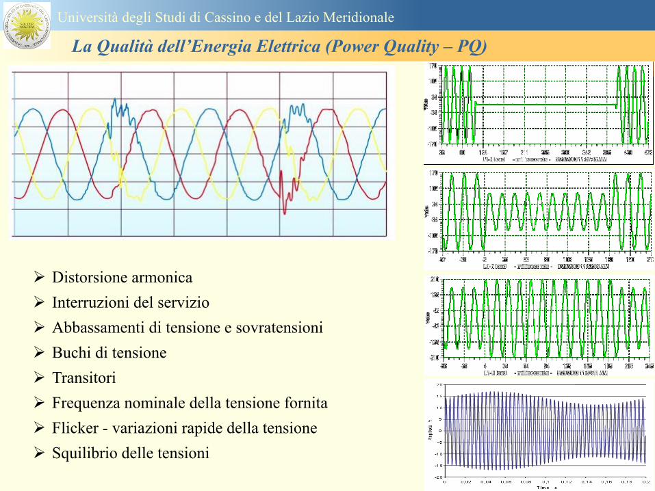
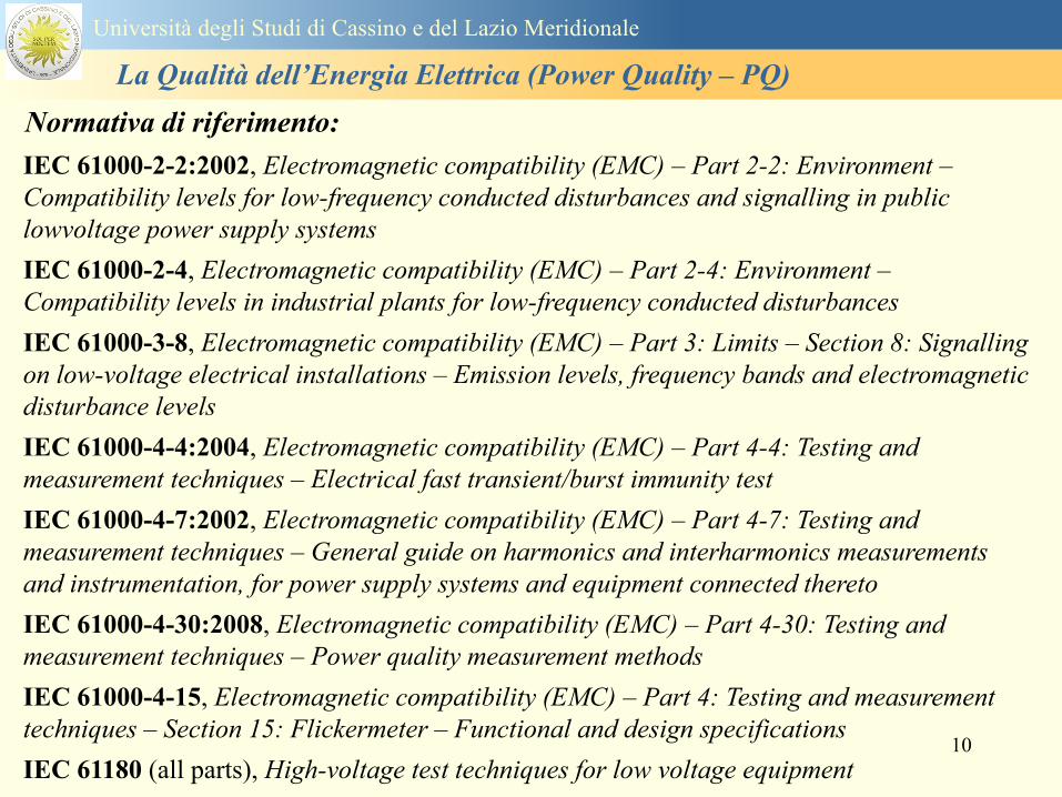
10
IEC 61000-2-22002 Electromagnetic compatibility (EMC) ndash Part 2-2 Environment ndash
Compatibility levels for low-frequency conducted disturbances and signalling in public
lowvoltage power supply systems
IEC 61000-2-4 Electromagnetic compatibility (EMC) ndash Part 2-4 Environment ndash
Compatibility levels in industrial plants for low-frequency conducted disturbances
IEC 61000-3-8 Electromagnetic compatibility (EMC) ndash Part 3 Limits ndash Section 8 Signalling
on low-voltage electrical installations ndash Emission levels frequency bands and electromagnetic
disturbance levels
IEC 61000-4-42004 Electromagnetic compatibility (EMC) ndash Part 4-4 Testing and
measurement techniques ndash Electrical fast transientburst immunity test
IEC 61000-4-72002 Electromagnetic compatibility (EMC) ndash Part 4-7 Testing and
measurement techniques ndash General guide on harmonics and interharmonics measurements
and instrumentation for power supply systems and equipment connected thereto
IEC 61000-4-302008 Electromagnetic compatibility (EMC) ndash Part 4-30 Testing and
measurement techniques ndash Power quality measurement methods
IEC 61000-4-15 Electromagnetic compatibility (EMC) ndash Part 4 Testing and measurement
techniques ndash Section 15 Flickermeter ndash Functional and design specifications
IEC 61180 (all parts) High-voltage test techniques for low voltage equipment
Normativa di riferimento
Universitagrave degli Studi di Cassino e del Lazio Meridionale
La Qualitagrave dellrsquoEnergia Elettrica (Power Quality ndash PQ)
11
IEC 61000 - 4 ndash 30 Norm
Seri 61000 Electromagnetic Compatibility
International Electrotechnical Commission
Part 4 Test and Measurement Tecniques
Section 30 PQ measurement methods
IEC 61000 - 4 ndash 7 Norm
Section 7 General guide on harmonics
and interharmonics measurements and
instrumentation for power supply
systems and equipment connected
thereto
Part 2 Environment ndashCompatibility levels
Seri 61000 Electromagnetic Compatibility
IEC International Electrotechnical Commission
Section xx details on the application sector
Part 3 Limits
Part 4 Test and Measurement Tecniques
Universitagrave degli Studi di Cassino e del Lazio Meridionale
La Qualitagrave dellrsquoEnergia Elettrica (Power Quality ndash PQ)
12
EN 501602010-07 Caratteristiche della tensione fornita dalle reti pubbliche di distribuzione
dellrsquoenergia elettrica
Descrive e specifica le caratteristiche principali della tensione ai terminali di
alimentazione di un utente della rete pubblica in bassa media e alta tensione in corrente
alternata in normali condizioni di esercizio Essa descrive i limiti o valori entro i quali le
caratteristiche della tensione possono essere attesi ai punti di alimentazione da reti elettriche
pubbliche europee e non descrive la situazione media sperimentata da un singolo utente di rete
Le caratteristiche della tensione fornite nella presente Norma non sono utilizzabili ai fini dei
limiti di EMC o di disturbi condotti nella rete pubblica Esse non sono utilizzabili ai fini di
prescrizioni nelle norme di prodotto o nelle norme per impianti
Normativa di riferimento
Universitagrave degli Studi di Cassino e del Lazio Meridionale
La Qualitagrave dellrsquoEnergia Elettrica (Power Quality ndash PQ)
13
Nel dettaglio la norma EN 50160 definisce i seguenti parametri
1 Frequenza nominale della tensione fornita
2 Ampiezza della tensione di alimentazione
3 Variazioni della tensione di alimentazione
4 Flicker - variazioni rapide della tensione
5 Buchi di tensione
6 Interruzioni della tensione di alimentazione
7 Squilibrio della tensione di alimentazione
8 Tensioni armoniche THD e fino al 25deg ordine
Universitagrave degli Studi di Cassino e del Lazio Meridionale
La Qualitagrave dellrsquoEnergia Elettrica (Power Quality ndash PQ)
14
Si specifica che qualora lrsquoazienda distributrice installi un registratore
della qualitagrave delle caratteristiche della tensione diverse dalle
interruzioni senza preavviso lunghe brevi e transitorie lo strumento
deve essere conforme alla norma tecnica EN 61000-4-30
Richiami nella delibera 042004
dellAUTORITA PER LENERGIA ELETTRICA E IL GAS
Il 30 gennaio 2004 con delibera 404 lrsquoautoritagrave dellrsquoenergia ha indicato tra i vari
argomenti trattati i criteri di misura delle qualitagrave della tensione
Nellrsquoarticolo 39 (pagina 29) viene indicato nel punto 391 e 2 che per la
registrazione di interruzioni senza preavviso lunghe brevi e transitorie occorre
utilizzare un registratore conforme alla CEI EN 50160 In questo caso lo strumento
registratore dice quando e per quanto si ha unrsquointerruzione del servizio ma a tutti gli
effetti NON EFFETTUA UNrsquoOSSERVAZIONE QUALITATIVA dei parametri
Universitagrave degli Studi di Cassino e del Lazio Meridionale
La Qualitagrave dellrsquoEnergia Elettrica (Power Quality ndash PQ)
15
Universitagrave degli Studi di Cassino e del Lazio Meridionale
La Qualitagrave dellrsquoEnergia Elettrica (Power Quality ndash PQ)
16
17
Universitagrave degli Studi di Cassino e del Lazio Meridionale
La Qualitagrave dellrsquoEnergia Elettrica (Power Quality ndash PQ)
CURVA DI TOLLERANZA AI DISTURBI
18
Caratteristiche dellrsquoalimentazione a bassa tensione
Universitagrave degli Studi di Cassino e del Lazio Meridionale
La Qualitagrave dellrsquoEnergia Elettrica (Power Quality ndash PQ)
19
Caratteristiche dellrsquoalimentazione a bassa tensione
Frequenza nominale
La frequenza nominale della tensione fornita deve essere di 50 Hz In condizioni normali
di esercizio il valore medio misurato nellrsquointervallo di 10 secondi deve essere
Per i sistemi con collegamento sincrono ad un sistema interconnesso
1 50 Hz plusmn 1 durante il 95 di un anno
2 50 Hz +4 - 6 durante il 100 di un anno
Per i sistemi senza collegamento sincrono ad un sistema interconnesso
1 50 Hz plusmn 2 durante il 95 di un anno
2 50 Hz plusmn 15 durante il 100 di un anno
Universitagrave degli Studi di Cassino e del Lazio Meridionale
La Qualitagrave dellrsquoEnergia Elettrica (Power Quality ndash PQ)
20
Caratteristiche dellrsquoalimentazione a bassa tensione
Universitagrave degli Studi di Cassino e del Lazio Meridionale
La Qualitagrave dellrsquoEnergia Elettrica (Power Quality ndash PQ)
21
Caratteristiche dellrsquoalimentazione a bassa tensione
Universitagrave degli Studi di Cassino e del Lazio Meridionale
La Qualitagrave dellrsquoEnergia Elettrica (Power Quality ndash PQ)
22
Variazioni della tensione di alimentazione (variazioni lente)
Le variazioni lente sono deviazioni ldquomedierdquo dal valore nominale dellrsquoampiezza della
tensione di consegna entro una fascia predefinita (per esempio del plusmn10) rispetto alla
tensione dichiarata
CAUSE variazione lenta dei carichi e dalla corrispondente azione di regolazione effettuata dai
variatori sotto carico dei trasformatori
Universitagrave degli Studi di Cassino e del Lazio Meridionale
La Qualitagrave dellrsquoEnergia Elettrica (Power Quality ndash PQ)
23
Variazioni della tensione di alimentazione (variazioni rapide)
Le variazioni rapide sono abbassamenti (o aumenti) bruschi di qualche percento della
tensione preesistente generalmente seguiti se abbassamenti da un ritorno (a rampa o di
altra forma) ad un valore intermedio tra quello preesistente e tra il minimo raggiunto
CAUSE commutazione dei carichi (partenza motori in particolare) funzionamento di carichi
con ciclo operativo particolarmente variabile e in qualche caso da manovre in rete (linee
trasformatori condensatori ecc)
Universitagrave degli Studi di Cassino e del Lazio Meridionale
La Qualitagrave dellrsquoEnergia Elettrica (Power Quality ndash PQ)
24
Flicker Il flicker egrave originato dalla fluttuazione della tensione Si definisce fluttuazione di tensione una
serie di variazioni rapide (uguali o diverse) della tensione
Fluttuazioni di tensione che presentano frequenze di modulazione del 50 Hz comprese tra 05 e
40 Hz danno origine al fenomeno del flicker (sfarfallio) ovvero della sensazione visiva
provocata dalle fluttuazioni dellrsquointensitagrave di illuminazione delle lampade
I suoi principali effetti sullrsquouomo possono essere mal di testa irritabilitagrave e fastidio agli occhi
Universitagrave degli Studi di Cassino e del Lazio Meridionale
La Qualitagrave dellrsquoEnergia Elettrica (Power Quality ndash PQ)
25
Universitagrave degli Studi di Cassino e del Lazio Meridionale
La Qualitagrave dellrsquoEnergia Elettrica (Power Quality ndash PQ)
26
La Qualitagrave dellrsquoEnergia Elettrica (Power Quality ndash PQ)
Universitagrave degli Studi di Cassino e del Lazio Meridionale
La Qualitagrave dellrsquoEnergia Elettrica (Power Quality ndash PQ)
27
Universitagrave degli Studi di Cassino e del Lazio Meridionale
La Qualitagrave dellrsquoEnergia Elettrica (Power Quality ndash PQ)
28
Universitagrave degli Studi di Cassino e del Lazio Meridionale
La Qualitagrave dellrsquoEnergia Elettrica (Power Quality ndash PQ)
29
Universitagrave degli Studi di Cassino e del Lazio Meridionale
La Qualitagrave dellrsquoEnergia Elettrica (Power Quality ndash PQ)
30
Universitagrave degli Studi di Cassino e del Lazio Meridionale
La Qualitagrave dellrsquoEnergia Elettrica (Power Quality ndash PQ)
31
Universitagrave degli Studi di Cassino e del Lazio Meridionale
La Qualitagrave dellrsquoEnergia Elettrica (Power Quality ndash PQ)
32
Buchi di tensione Riduzione temporanea della tensione in un punto della rete elettrica sotto una determinata
soglia Se durante un buco la tensione scende sotto una soglia di interruzione lrsquoevento egrave
considerato essere sia un buco che unrsquointerruzione
CAUSE I buchi di tensione sono generalmente dovuti a guasti che sopravvengono negli
impianti utilizzatori o nel sistema di distribuzione pubblico Possono dipendere anche variazioni
di carico lungo la linea
Universitagrave degli Studi di Cassino e del Lazio Meridionale
La Qualitagrave dellrsquoEnergia Elettrica (Power Quality ndash PQ)
33
Interruzioni della tensione di alimentazione Condizione in cui la tensione ad un terminale della rete egrave inferiore allrsquo1 della tensione
nominale per una durata fino a tre minuti (brevi) o maggiori di 3 minuti (lunghe)
Universitagrave degli Studi di Cassino e del Lazio Meridionale
La Qualitagrave dellrsquoEnergia Elettrica (Power Quality ndash PQ)
34
Sovratensioni temporanee alla frequenza di rete fra fasi e terra Le sovratensioni sono sopraelevazioni della tensione conseguenti a modificazioni dello
stato elettrico della rete elettrica
Universitagrave degli Studi di Cassino e del Lazio Meridionale
La Qualitagrave dellrsquoEnergia Elettrica (Power Quality ndash PQ)
35
Armoniche Le armoniche sono tensioni o correnti sinusoidali con frequenza pari ad un multiplo intero
(ordine) della frequenza fondamentale di funzionamento del sistema elettrico la cui
presenza determina una distorsione della forma drsquoonda della tensione di alimentazione
CAUSE In piccola parte dal sistema stesso (trasformatori etc) e per la maggior parte da
apparecchi utilizzatori carichi commutati elettronicamente raddrizzatori convertitori regolatori
in AC cicloconvertitori ecc carichi con caratteristiche non lineari apparecchiature a
saturazione magnetica lampade a scarica forni ad arco saldatrici ad arco trasformatori ecc
bull carichi inseriti e disinseriti da organi di manovra condensatori filtri e motori a induzione
Universitagrave degli Studi di Cassino e del Lazio Meridionale
La Qualitagrave dellrsquoEnergia Elettrica (Power Quality ndash PQ)
36
Armoniche di tensione e corrente ndash Problemi
Vi sono diversi ambiti causati dalle armoniche
bull problemi causati da armoniche di corrente
1048707 sovraccarico del neutro
1048707 aumento delle perdite nei trasformatori
1048707 interventi intempestivi degli interruttori automatici
1048707 aumento dellrsquoeffetto pelle
bull problemi causati da armoniche di tensione
1048707 deformazione della tensione
1048707 disturbi nella coppia dei motori ad induzione
1048707 rumore al passaggio per lo zero
bull problemi causati quando le armoniche di corrente raggiungono lrsquoalimentazione
Universitagrave degli Studi di Cassino e del Lazio Meridionale
La Qualitagrave dellrsquoEnergia Elettrica (Power Quality ndash PQ)
37
38
Universitagrave degli Studi di Cassino e del Lazio Meridionale
La Qualitagrave dellrsquoEnergia Elettrica (Power Quality ndash PQ)
39
Strumentazione ldquohand heldrdquo con display
Universitagrave degli Studi di Cassino e del Lazio Meridionale
La Qualitagrave dellrsquoEnergia Elettrica (Power Quality ndash PQ)
40
Strumentazione ldquohand heldrdquo con display
Universitagrave degli Studi di Cassino e del Lazio Meridionale
La Qualitagrave dellrsquoEnergia Elettrica (Power Quality ndash PQ)
41
Strumentazione da registrazione
Universitagrave degli Studi di Cassino e del Lazio Meridionale
La Qualitagrave dellrsquoEnergia Elettrica (Power Quality ndash PQ)
42
Schema di principio ndash 61000-4-30 copy IEC2008
The electrical quantity to be measured may be either directly accessible as is
generally the case in low-voltage systems or accessible via measurement
transducers
An instrument may include the whole measurement chain In this standard the
normative part does not consider the measurement transducers external to the
instrument and their associated uncertainty
Universitagrave degli Studi di Cassino e del Lazio Meridionale
La Qualitagrave dellrsquoEnergia Elettrica (Power Quality ndash PQ)
43
Universitagrave degli Studi di Cassino Corso di Fondamenti di Misure
La Qualitagrave dellrsquoEnergia Elettrica (Power Quality ndash PQ)
Classi dei metodi di misura - 61000-4-30 copy IEC2008
For each class measurement methods and appropriate performance requirements
are included
Sono definite tre classi A S e B
Class A
This class is used where precise measurements are necessary for example for contractual
applications that may require resolving disputes verifying compliance with standards etc
Any measurements of a parameter carried out with two different instruments complying with
the requirements of Class A when measuring the same signals will produce matching results
within the specified uncertainty for that parameter
Class S
This class is used for statistical applications such as surveys or power quality assessment
possibly with a limited subset of parameters Although it uses equivalent intervals of
measurement as class A the class S processing requirements are lower
Class B
This class is defined in order to avoid making many existing instruments designs obsolete
NOTE Class B methods are not recommended for new designs Readers are advised that Class B may be removed in a
future Edition of this standard
44
Classi dei metodi di misura - 61000-4-30 copy IEC2008
Measurement aggregation over time intervals
CLASS A
The basic measurement time interval for parameter magnitudes (supply voltage harmonics
interharmonics and unbalance) shall be a 10-cycle time interval for a 50 Hz power system
or 12-cycle time interval for a 60 Hz power system
The 1012-cycle measurement shall be re-synchronized at every RTC 10 min tick
The 1012-cycle values are then aggregated over 3 additional intervals
ndash 150180-cycle interval (150 cycles for 50 Hz nominal or 180 cycles for 60 Hz nominal)
ndash 10 min interval
ndash 2 h interval
CLASS S
Same time intervals as Class A
CLASS B
The manufacturer shall specify the number and duration of aggregation time intervals
Universitagrave degli Studi di Cassino e del Lazio Meridionale
La Qualitagrave dellrsquoEnergia Elettrica (Power Quality ndash PQ)
45
Universitagrave degli Studi di Cassino e del Lazio Meridionale
La Qualitagrave dellrsquoEnergia Elettrica (Power Quality ndash PQ)
46
Universitagrave degli Studi di Cassino e del Lazio Meridionale
La Qualitagrave dellrsquoEnergia Elettrica (Power Quality ndash PQ)
Class A
The 10-min aggregated value shall be tagged with the absolute time (for
example 01H1000) The time tag is the time at the conclusion of the 10-min
aggregation
The data for the 10-min time interval shall be aggregated from 1012-cycle time
intervals
Each 10-minute interval shall begin on a UTC 10-min tick The 10-min tick is
also used to re-synchronize the 1012-cycle intervals and the 150180-cycle
intervals
The final 1012-cycle interval(s) in a 10-min aggregation period will typically
overlap in time with the UTC 10-min clock tick Any overlapping 1012-cycle
interval (Overlap 1 in Figure 2) is included in the aggregation of the previous
10-min interval
47
Universitagrave degli Studi di Cassino e del Lazio Meridionale
La Qualitagrave dellrsquoEnergia Elettrica (Power Quality ndash PQ)
48
Universitagrave degli Studi di Cassino e del Lazio Meridionale
La Qualitagrave dellrsquoEnergia Elettrica (Power Quality ndash PQ)
49
Classi dei metodi di misura - 61000-4-30 copy IEC2008
Real time clock (RTC) uncertainty
Sono definite le specifiche per le 3 classi
Flagging concept
During a dip swell or interruption the measurement algorithm for other
parameters (for example frequency measurement) might produce an unreliable
value The flagging concept therefore avoids counting a single event more than
once in different parameters (for example counting a single dip as both a dip and a
frequency variation) and indicates that an aggregated value might be unreliable
Universitagrave degli Studi di Cassino e del Lazio Meridionale
La Qualitagrave dellrsquoEnergia Elettrica (Power Quality ndash PQ)
50
Classi dei metodi di misura - 61000-4-30 copy IEC2008
Power quality parameters - INDICES
Per ogni parametro viene suggerito il metodo di misura per le tre classi e
(soprattutto) le caratteristiche di precisione Per alcuni parametri rimanda a
specifiche norme (ad esempio Flicker e Armonicheinterarmoniche)
Esempio - Power frequency Class A
The frequency reading shall be obtained every 10 s As power frequency may not be exactly 50 Hz or 60
Hz within the 10 s time clock interval the number of cycles may not be an integer number The
fundamental frequency output is the ratio of the number of integral cycles counted during the 10 s time
clock interval divided by the cumulative duration of the integer cycles Before each assessment
harmonics and interharmonics shall be attenuated to minimize the effects of multiple zero crossings
The measurement time intervals shall be non-overlapping Individual cycles that overlap the 10 s time
clock are discarded Each 10 s interval shall begin on an absolute 10 s time clock with uncertainty as
defined in 46
Other techniques that provide equivalent results such as convolution are acceptable
Class S Same as class A
Class B The manufacturer shall specify the process used for frequency measurement
Universitagrave degli Studi di Cassino e del Lazio Meridionale
La Qualitagrave dellrsquoEnergia Elettrica (Power Quality ndash PQ)
51
Classi dei metodi di misura - 61000-4-30 copy IEC2008
Power quality parameters - INDICES
Per ogni parametro viene suggerito il metodo di misura per le tre classi e
(soprattutto) le caratteristiche di precisione Per alcuni parametri rimanda a
specifiche norme (ad esempio Flicker e Armonicheinterarmoniche)
Esempio - Power frequency
Measurement uncertainty and measuring range
ndash Class A
Under the conditions described in 61 the measurement uncertainty shall not exceed
plusmn10 mHz over the measuring ranges 425 Hz ~ 575 Hz 51 Hz ~ 69 Hz
ndash Class S
Under the conditions described in 61 the measurement uncertainty shall not exceed
plusmn50 mHz over the measuring ranges 425 Hz ~ 575 Hz 51 Hz ~ 69 Hz
ndash Class B
The manufacturer shall specify the uncertainty over the measuring ranges 425 Hz ~
575 Hz 51 Hz ~ 69 Hz
Universitagrave degli Studi di Cassino e del Lazio Meridionale
La Qualitagrave dellrsquoEnergia Elettrica (Power Quality ndash PQ)
52
Magnitude of the supply voltage
Measurement method
ndash Class A
The measurement shall be the rms value of the voltage magnitude over
a 10-cycle time interval for 50 Hz power system or 12-cycle time
interval for 60 Hz power system Every 1012-cycle interval shall be
contiguous and not overlapping with adjacent 1012-cycle intervals
except as shown as Overlap 1 in Figure 2
NOTE 1 This specific measurement method is used for quasi-stationary signals and is
not used for the detection and measurement of disturbances dips swells voltage
interruptions and transients
NOTE 2 The rms value includes by definition harmonics interharmonics mains
signalling etc
- Class S same as Class A
Universitagrave degli Studi di Cassino e del Lazio Meridionale
La Qualitagrave dellrsquoEnergia Elettrica (Power Quality ndash PQ)
53
Magnitude of the supply voltage
Measurement uncertainty and measuring range
ndash Class A
Under the conditions described in Clause 6 the measurement uncertainty
shall not exceed plusmn01 of Udin over the range of 10 ~ 150 of Udin
ndash Class S
Under the conditions described in Clause 6 the measurement uncertainty
shall not exceed plusmn05 of Udin over the range of 20 ~ 120 of Udin
Universitagrave degli Studi di Cassino e del Lazio Meridionale
La Qualitagrave dellrsquoEnergia Elettrica (Power Quality ndash PQ)
54
Supply voltage dips and swells
Measurement method
ndash Class A
The basic measurement Urms of a voltage dip and swell shall be the
Urms(frac12) on each measurement channel (see Clause 322)
The cycle duration for Urms(frac12) depends on the frequency The
frequency might be determined by the last non-flagged power frequency
measurement (see Clause 47 and Clause 51) or by any other method
that yields the uncertainty requirements of Clause 6
NOTE 1 The Urms(frac12) value includes by definition harmonics interharmonics mains
signalling voltage etc
NOTE 2 It is important to avoid loss of data when dips and swells occur in a rapid
sequence (for example three events in one second with up to one minute between
sequences may occur when a recloser operates into a sustained fault) If during a rapid
burst the dipswell event characteristics cannot be recorded then a count of events may
be useful
Universitagrave degli Studi di Cassino e del Lazio Meridionale
La Qualitagrave dellrsquoEnergia Elettrica (Power Quality ndash PQ)
55
Supply voltage dips and swells
Detection and evaluation of a voltage dip
Voltage dip detection
The dip threshold is a percentage of either Udin or the sliding voltage
reference Usr (see 525 544) The user shall declare the reference
voltage in use
NOTE ndash On single-phase systems a voltage dip begins when the Urms voltage falls
below the dip threshold and ends when the Urms voltage is equal to or above the dip
threshold plus the hysteresis voltage
ndash On polyphase systems a dip begins when the Urms voltage of one or more channels is
below the dip threshold and ends when the Urms voltage on all measured channels is
equal to or above the dip threshold plus the hysteresis voltage
The dip threshold and the hysteresis voltage are both set by the user according to the
use
Universitagrave degli Studi di Cassino e del Lazio Meridionale
La Qualitagrave dellrsquoEnergia Elettrica (Power Quality ndash PQ)
56
Calculation of a sliding reference voltage
The sliding reference voltage implementation is optional not mandatory
If a sliding reference is chosen for voltage dip or swell detection this
shall be calculated using a first-order filter with a 1-min time constant
This filter is given by
Usr(n) = 09967 times Usr(nndash1) + 00033 times U(1012)rms
where
Usr(n) is the present value of the sliding reference voltage
Usr(nndash1) is the previous value of the sliding reference voltage and
U(1012)rms is the most recent 1012-cycle rms value
When the measurement is started the initial value of the sliding reference voltage is set
to the declared input voltage The sliding reference voltage is updated every 1012-
cycles If a 1012-cycle value is flagged the sliding reference voltage is not updated
and the previous value is used
Universitagrave degli Studi di Cassino e del Lazio Meridionale
La Qualitagrave dellrsquoEnergia Elettrica (Power Quality ndash PQ)
57
Supply voltage dips and swells
Voltage dip evaluation
A voltage dip is characterized by a pair of data either residual voltage
(Ures) or depth and duration
ndash the residual voltage of a voltage dip is the lowest Urms(frac12) value
measured on any channel during the dip
ndash the depth is the difference between the reference voltage (either Udin
or Usr) and the residual voltage It is generally expressed in percentage
of the reference voltage
NOTE 1 During the dip it may be useful to also record the lowest Urms(frac12) on each
channel in addition to the residual voltage of the dip The duration spent below the dip
threshold on each channel may also be useful
Universitagrave degli Studi di Cassino e del Lazio Meridionale
La Qualitagrave dellrsquoEnergia Elettrica (Power Quality ndash PQ)
58
Supply voltage dips and swells
Voltage dip evaluation
NOTE 2 If voltage waveforms are recorded before during and after a
dip useful information about phase angle changes may be available in
the recorded data
The start time of a dip shall be time stamped with the time of the start of
the Urms of the channel that initiated the event and the end time of the
dip shall be the time stamped with the time of the end of the Urms that
ended the event as defined by the threshold plus the hysteresis
The duration of a voltage dip is the time difference between the start
time and the end time of the voltage dip
Universitagrave degli Studi di Cassino e del Lazio Meridionale
La Qualitagrave dellrsquoEnergia Elettrica (Power Quality ndash PQ)
59
Supply voltage dips and swells
Residual voltage and swell voltage magnitude measurement
uncertainty
ndash Class A
The measurement uncertainty shall not exceed plusmn02 of Udin
ndash Class S
The measurement uncertainty shall not exceed plusmn10 of Udin
Universitagrave degli Studi di Cassino e del Lazio Meridionale
La Qualitagrave dellrsquoEnergia Elettrica (Power Quality ndash PQ)
60
Schema di principio ndash 61000-4-7 copy IEC2002
Universitagrave degli Studi di Cassino e del Lazio Meridionale
La Qualitagrave dellrsquoEnergia Elettrica (Power Quality ndash PQ)
61
Universitagrave degli Studi di Cassino e del Lazio Meridionale
La Qualitagrave dellrsquoEnergia Elettrica (Power Quality ndash PQ)
62
Universitagrave degli Studi di Cassino e del Lazio Meridionale
La Qualitagrave dellrsquoEnergia Elettrica (Power Quality ndash PQ)
63
Inter-Armoniche Le inter-armoniche sono tensioni o correnti sinusoidali con frequenza diversa da un
multiplo intero della fondamentale la cui presenza determina una distorsione
(modulazione) della forma donda della tensione di alimentazione
CAUSE dai carichi che assorbono correnti inter-armoniche
- carichi commutati elettronicamente convertitori cascata subsincrona cicloconvertitori regolatori con
controllo a pacchetti di cicli ecc
- carichi con caratteristiche non lineari eo non stazionarie forni ad arco saldatrici ad arco ecc
Universitagrave degli Studi di Cassino e del Lazio Meridionale
La Qualitagrave dellrsquoEnergia Elettrica (Power Quality ndash PQ)
64
Universitagrave degli Studi di Cassino e del Lazio Meridionale
La Qualitagrave dellrsquoEnergia Elettrica (Power Quality ndash PQ)
Un porsquo di esempi e
consigli praticihellip
65
0V
50V
100V
150V
200V
250V
300V
350V
0ms 5ms 10ms 15ms 20ms
t
u
0A
1A
2A
3A
i
0V
50V
100V
150V
200V
250V
300V
350V
0ms 5ms 10ms 15ms 20ms
t
u
0A
1A
2A
3A
i
0V
50V
100V
150V
200V
250V
300V
350V
0ms 5ms 10ms 15ms 20ms
t
u
0A
1A
2A
3A
i
gleichgerichtete
Netzspannung
Kondensator-
spannung
gleichgerichteter
Netzstrom
The situation
today
bull Computed current and voltage profiles when a
230 V 58 W fluorescent lamp with an old-style
electronic ballast is driven on the phase wire of
a typical power distribution system
System voltage 230 V
System frequency 50 Hz
Source resistance 500 mW
Longitudinal induction 904 microH
System impedance 575 mW
Mean dc current 180 mA
Smoothing capacitance220 microF
66
And what about electronic ballasts that are rated over 25W
Introduce electronic power factor correction (PFC)
0V
20V
40V
60V
80V
100V
120V
140V
160V
180V
200V
220V
0deg 15deg 30deg 45deg
u
00A
03A
06A
09A
12A
i
67
Though todayrsquos ballasts are better if
rated gt25 W bull Only
the
small
ones
continu
e to
pollute
just like
PCs
TV sets
do
68
This leads to a number of
previously unknown effects bull 1 Deformed voltage curves
bull 2 Huge inrush current peaks
bull 3 Instrument dependent measured parameters
bull 4 Increased loading of phase conductors
bull 5 Loading and overloading of the neutral conductor
bull 6 Overheating and start-up problems of induction motors
bull 7 Additional stray losses in transformers
bull 8 Repercussions of generators upon the mains
bull 9 Influence of capacitors repercussions upon the mains
and four additional complications in TN-C systems
10 Stray currents in equipotential bonding system magnetic fields
11 Contamination of data streams by stray currents
12 Stray currents in the earthing system corrosion damage
13 Lightning currents in devices and equipment
69
1 Deformed voltage curves
bull in theory
-350V
-300V
-250V
-200V
-150V
-100V
-50V
0V
50V
100V
150V
200V
250V
300V
350V
0 5 10 15 20
t ms
u
System voltage profile when driving
a single-phase load comprising
twenty 58 W energy-saver lamps in
parallel on a typical 230 V power
system
70
and in practice
bull An actual
current profile
bull
bull and
bull a voltage profile
bull
bull recorded in a large storage
dispatch and administrative
building
71
at home or in industrial environments
bull
bull Television 40
W
bull 200 Vdiv 2
Adiv
bull 5 msdiv
Harmonic
spectrum
Frequency
converter
50 Adiv
Phase currents
I1=I2=I3=160 A
IN=295 A
5 msdiv
72
Every periodic waveform can be written
as the infinite sum of sinusoidal waves
-175
-150
-125
-100
-75
-50
-25
0
25
50
75
100
125
150
175
0 5 10 15 20
t ms
i
mA
itot
i1
Synthesis of a triangular current profile 100mA
Content fundamental I = 99 mA Isup2 = 9855 mAsup2
Sum of squares Isup2 = 9855 mAsup2
Root of sum = RMS value I = 99 mA
-175
-150
-125
-100
-75
-50
-25
0
25
50
75
100
125
150
175
0 5 10 15 20
t ms
i
mA
itot
i1
i3
Synthesis of a triangular current profile 100mA
Content fundamental I = 99 mA Isup2 = 9855 mAsup2
Cont 3 rd harmonic I = -11 mA Isup2 = 122 mAsup2
Sum of squares Isup2 = 9977 mAsup2
Root of sum = RMS value I = 100 mA
-175
-150
-125
-100
-75
-50
-25
0
25
50
75
100
125
150
175
0 5 10 15 20
t ms
i
mA
itot
i1
i3
i5
Synthesis of a triangular current profile 100mA
Content fundamental I = 99 mA Isup2 = 9855 mAsup2
Cont 3 rd harmonic I = -11 mA Isup2 = 122 mAsup2
Cont 5 th harmonic I = 4 mA Isup2 = 16 mAsup2
Sum of squares Isup2 = 9993 mAsup2
Root of sum = RMS value I = 100 mA
-175
-150
-125
-100
-75
-50
-25
0
25
50
75
100
125
150
175
0 5 10 15 20
t ms
i
mA
itot
i1
i3
i5
i7
Synthesis of a triangular current profile 100mA
Content fundamental I = 99 mA Isup2 = 9855 mAsup2
Cont 3 rd harmonic I = -11 mA Isup2 = 122 mAsup2
Cont 5 th harmonic I = 4 mA Isup2 = 16 mAsup2
Cont 7 th harmonic I = -2 mA Isup2 = 4 mAsup2
Sum of squares Isup2 = 9997 mAsup2
Root of sum = RMS value I = 100 mA
-175
-150
-125
-100
-75
-50
-25
0
25
50
75
100
125
150
175
0 5 10 15 20
t ms
i
mA
itot i1
i3 i5
i7 i9
Synthesis of a triangular current profile 100mA
Content fundamental I = 99 mA Isup2 = 9855 mAsup2
Cont 3 rd harmonic I = -11 mA Isup2 = 122 mAsup2
Cont 5 th harmonic I = 4 mA Isup2 = 16 mAsup2
Cont 7 th harmonic I = -2 mA Isup2 = 4 mAsup2
Cont 9 th harmonic I = 1 mA Isup2 = 2 mAsup2
Sum of squares Isup2 = 9998 mAsup2
Root of sum = RMS value I = 100 mA
-175
-150
-125
-100
-75
-50
-25
0
25
50
75
100
125
150
175
0 5 10 15 20
t ms
i
mA
itot i1
i3 i5
i7 i9
i11
Synthesis of a triangular current profile 100mA
Content fundamental I = 99 mA Isup2 = 9855 mAsup2
Cont 3 rd harmonic I = -11 mA Isup2 = 122 mAsup2
Cont 5 th harmonic I = 4 mA Isup2 = 16 mAsup2
Cont 7 th harmonic I = -2 mA Isup2 = 4 mAsup2
Cont 9 th harmonic I = 1 mA Isup2 = 2 mAsup2
Cont 11 th harmonic I = -1 mA Isup2 = 1 mAsup2
Sum of squares Isup2 = 9999 mAsup2
Root of sum = RMS value I = 100 mA
-175
-150
-125
-100
-75
-50
-25
0
25
50
75
100
125
150
175
0 5 10 15 20
t ms
i
mA
itot i1
i3 i5
i7 i9
i11 i13
Synthesis of a triangular current profile 100mA
Content fundamental I = 99 mA Isup2 = 9855 mAsup2
Cont 3 rd harmonic I = -11 mA Isup2 = 122 mAsup2
Cont 5 th harmonic I = 4 mA Isup2 = 16 mAsup2
Cont 7 th harmonic I = -2 mA Isup2 = 4 mAsup2
Cont 9 th harmonic I = 1 mA Isup2 = 2 mAsup2
Cont 11 th harmonic I = -1 mA Isup2 = 1 mAsup2
Cont 13 th harmonic I = 1 mA Isup2 = 0 mAsup2
Sum of squares Isup2 = 9999 mAsup2
Root of sum = RMS value I = 100 mA
-175
-150
-125
-100
-75
-50
-25
0
25
50
75
100
125
150
175
0 5 10 15 20
t ms
i
mA
itot i1
i3 i5
i7 i9
i11 i13
i15
Synthesis of a triangular current profile 100mA
Content fundamental I = 99 mA Isup2 = 9855 mAsup2
Cont 3 rd harmonic I = -11 mA Isup2 = 122 mAsup2
Cont 5 th harmonic I = 4 mA Isup2 = 16 mAsup2
Cont 7 th harmonic I = -2 mA Isup2 = 4 mAsup2
Cont 9 th harmonic I = 1 mA Isup2 = 2 mAsup2
Cont 11 th harmonic I = -1 mA Isup2 = 1 mAsup2
Cont 13 th harmonic I = 1 mA Isup2 = 0 mAsup2
Cont 15 th harmonic I = 0 mA Isup2 = 0 mAsup2
Sum of squares Isup2 = 10000 mAsup2
Root of sum = RMS value I = 100 mA
-175
-150
-125
-100
-75
-50
-25
0
25
50
75
100
125
150
175
0 5 10 15 20
t ms
i
mA
itot i1
i3 i5
i7 i9
i11 i13
i15 i17
Synthesis of a triangular current profile 100mA
Content fundamental I = 99 mA Isup2 = 9855 mAsup2
Cont 3 rd harmonic I = -11 mA Isup2 = 122 mAsup2
Cont 5 th harmonic I = 4 mA Isup2 = 16 mAsup2
Cont 7 th harmonic I = -2 mA Isup2 = 4 mAsup2
Cont 9 th harmonic I = 1 mA Isup2 = 2 mAsup2
Cont 11 th harmonic I = -1 mA Isup2 = 1 mAsup2
Cont 13 th harmonic I = 1 mA Isup2 = 0 mAsup2
Cont 15 th harmonic I = 0 mA Isup2 = 0 mAsup2
Cont 17 th harmonic I = 0 mA Isup2 = 0 mAsup2
Sum of squares Isup2 = 10000 mAsup2
Root of sum = RMS value I = 100 mA
73
whose frequencies called harmonics are
integer multiples of the fundamental frequency
-175
-150
-125
-100
-75
-50
-25
0
25
50
75
100
125
150
175
0 5 10 15 20
t ms
i
mA
itot
i1
Synthesis of a rectangular current profile 100mA
Content fundamental I = 90 mA Isup2 = 8106 mAsup2
Sum of squares Isup2 = 8106 mAsup2
Root of sum = RMS value I = 90 mA
-175
-150
-125
-100
-75
-50
-25
0
25
50
75
100
125
150
175
0 5 10 15 20
t ms
i
mA
itot
i1
i3
Synthesis of a rectangular current profile 100mA
Content fundamental I = 90 mA Isup2 = 8106 mAsup2
Cont 3 rd harmonic I = 30 mA Isup2 = 901 mAsup2
Sum of squares Isup2 = 9006 mAsup2
Root of sum = RMS value I = 95 mA
-175
-150
-125
-100
-75
-50
-25
0
25
50
75
100
125
150
175
0 5 10 15 20
t ms
i
mA
itot
i1
i3
i5
Synthesis of a rectangular current profile 100mA
Content fundamental I = 90 mA Isup2 = 8106 mAsup2
Cont 3 rd harmonic I = 30 mA Isup2 = 901 mAsup2
Cont 5 th harmonic I = 18 mA Isup2 = 324 mAsup2
Sum of squares Isup2 = 9331 mAsup2
Root of sum = RMS value I = 97 mA
-175
-150
-125
-100
-75
-50
-25
0
25
50
75
100
125
150
175
0 5 10 15 20
t ms
i
mA
itot
i1
i3
i5
i7
Synthesis of a rectangular current profile 100mA
Content fundamental I = 90 mA Isup2 = 8106 mAsup2
Cont 3 rd harmonic I = 30 mA Isup2 = 901 mAsup2
Cont 5 th harmonic I = 18 mA Isup2 = 324 mAsup2
Cont 7 th harmonic I = 13 mA Isup2 = 165 mAsup2
Sum of squares Isup2 = 9496 mAsup2
Root of sum = RMS value I = 97 mA
-175
-150
-125
-100
-75
-50
-25
0
25
50
75
100
125
150
175
0 5 10 15 20
t ms
i
mA
itot i1
i3 i5
i7 i9
Synthesis of a rectangular current profile 100mA
Content fundamental I = 90 mA Isup2 = 8106 mAsup2
Cont 3 rd harmonic I = 30 mA Isup2 = 901 mAsup2
Cont 5 th harmonic I = 18 mA Isup2 = 324 mAsup2
Cont 7 th harmonic I = 13 mA Isup2 = 165 mAsup2
Cont 9 th harmonic I = 10 mA Isup2 = 100 mAsup2
Sum of squares Isup2 = 9596 mAsup2
Root of sum = RMS value I = 98 mA
-175
-150
-125
-100
-75
-50
-25
0
25
50
75
100
125
150
175
0 5 10 15 20
t ms
i
mA
itot i1
i3 i5
i7 i9
i11
Synthesis of a rectangular current profile 100mA
Content fundamental I = 90 mA Isup2 = 8106 mAsup2
Cont 3 rd harmonic I = 30 mA Isup2 = 901 mAsup2
Cont 5 th harmonic I = 18 mA Isup2 = 324 mAsup2
Cont 7 th harmonic I = 13 mA Isup2 = 165 mAsup2
Cont 9 th harmonic I = 10 mA Isup2 = 100 mAsup2
Cont 11 th harmonic I = 8 mA Isup2 = 67 mAsup2
Sum of squares Isup2 = 9663 mAsup2
Root of sum = RMS value I = 98 mA
-175
-150
-125
-100
-75
-50
-25
0
25
50
75
100
125
150
175
0 5 10 15 20
t ms
i
mA
itot i1
i3 i5
i7 i9
i11 i13
Synthesis of a rectangular current profile 100mA
Content fundamental I = 90 mA Isup2 = 8106 mAsup2
Cont 3 rd harmonic I = 30 mA Isup2 = 901 mAsup2
Cont 5 th harmonic I = 18 mA Isup2 = 324 mAsup2
Cont 7 th harmonic I = 13 mA Isup2 = 165 mAsup2
Cont 9 th harmonic I = 10 mA Isup2 = 100 mAsup2
Cont 11 th harmonic I = 8 mA Isup2 = 67 mAsup2
Cont 13 th harmonic I = 7 mA Isup2 = 48 mAsup2
Sum of squares Isup2 = 9711 mAsup2
Root of sum = RMS value I = 99 mA
-175
-150
-125
-100
-75
-50
-25
0
25
50
75
100
125
150
175
0 5 10 15 20
t ms
i
mA
itot i1
i3 i5
i7 i9
i11 i13
i15
Synthesis of a rectangular current profile 100mA
Content fundamental I = 90 mA Isup2 = 8106 mAsup2
Cont 3 rd harmonic I = 30 mA Isup2 = 901 mAsup2
Cont 5 th harmonic I = 18 mA Isup2 = 324 mAsup2
Cont 7 th harmonic I = 13 mA Isup2 = 165 mAsup2
Cont 9 th harmonic I = 10 mA Isup2 = 100 mAsup2
Cont 11 th harmonic I = 8 mA Isup2 = 67 mAsup2
Cont 13 th harmonic I = 7 mA Isup2 = 48 mAsup2
Cont 15 th harmonic I = 6 mA Isup2 = 36 mAsup2
Sum of squares Isup2 = 9747 mAsup2
Root of sum = RMS value I = 99 mA
-175
-150
-125
-100
-75
-50
-25
0
25
50
75
100
125
150
175
0 5 10 15 20
t ms
i
mA
itot i1
i3 i5
i7 i9
i11 i13
i15 i17
Synthesis of a rectangular current profile 100mA
Content fundamental I = 90 mA Isup2 = 8106 mAsup2
Cont 3 rd harmonic I = 30 mA Isup2 = 901 mAsup2
Cont 5 th harmonic I = 18 mA Isup2 = 324 mAsup2
Cont 7 th harmonic I = 13 mA Isup2 = 165 mAsup2
Cont 9 th harmonic I = 10 mA Isup2 = 100 mAsup2
Cont 11 th harmonic I = 8 mA Isup2 = 67 mAsup2
Cont 13 th harmonic I = 7 mA Isup2 = 48 mAsup2
Cont 15 th harmonic I = 6 mA Isup2 = 36 mAsup2
Cont 17 th harmonic I = 5 mA Isup2 = 28 mAsup2
Sum of squares Isup2 = 9775 mAsup2
Root of sum = RMS value I = 99 mA
74
Even far better simulations are
available free of charge at
bull wwwpowerstandardscomMcEachern
75
-4A
-3A
-2A
-1A
0A
1A
2A
3A
4A
0ms 5ms 10ms 15ms 20ms
t
i
-4A
-3A
-2A
-1A
0A
1A
2A
3A
4A
0ms 5ms 10ms 15ms 20ms
t
i
Applying the Fourier
analysis to a real PC
current does not work
directly
bull
bull but it can be
modelled by a similar
triangular curve in
which not all of the
higher harmonics
have been included
Triangular current profile of
the same amplitude and a
pulse duty cycle of 17
Input current of a PC
with monitor
76
Analysis of the model triangular waveform
-400
-350
-300
-250
-200
-150
-100
-50
0
50
100
150
200
250
300
350
400
0 5 10 15 20
t ms
iI
itot(t) L1 [A] i1(t) L1 [A]
i3(t) L1 [A] i5(t) L1 [A]
i7(t) L1 [A] i9(t) L1 [A]
i11(t) L1 [A] i13(t) L1 [A]
i15(t) L1 [A] i17(t) L1 [A]
77
M3
Harmonics
Energy
(active
power)
L1
L2
L3
N
PE
Important
bull Harmonics are created within the loads
themselves and can flow ldquoupstreamrdquo to
contaminate the power system
78
-6A
-5A
-4A
-3A
-2A
-1A
0A
1A
2A
3A
4A
5A
6A
0ms 5ms 10ms 15ms 20ms
t
i
Squared values
Without
Fundamental 502 mA 251986 mAsup2 the fundamental
3rd harmonic -479 mA 229000 mAsup2 229000 mAsup2
5th harmonic 434 mA 188595 mAsup2 188595 mAsup2
7th harmonic -374 mA 139903 mAsup2 139903 mAsup2
9th harmonic 304 mA 92527 mAsup2 92527 mAsup2
11th harmonic -232 mA 53671 mAsup2 53671 mAsup2
13th harmonic 163 mA 26600 mAsup2 26600 mAsup2
15th harmonic -104 mA 10780 mAsup2 10780 mAsup2
17th harmonic 57 mA 3299 mAsup2 3299 mAsup2
Sum of the squares 996362 mAsup2 744377 mAsup2
Root thereof 998 mAeff THD = 863 mA
What actually is THD Example shown here triangular current
profile with an rms current of 1000 mA
and a pulse duty cycle of 17
THDr (root mean square) = 863mA1000mA = 86
THDf (fundamental) = 863mA502mA = 172
79
Effect on phase-to-neutral
and phase-to-phase voltages
bull Recorded
on June
30 2002
230 p
m
bull What
was the
matter
then
bull The
soccer
final
Germany
vs
Brazil
80
The triple-N harmonics drive
a circulating current in the
delta winding of a distribution
transformer
bull but the
bull voltage harmonics
propagate into the next
low-voltage power
distribution system
81 0V
50V
100V
150V
200V
250V
300V
350V
400V
450V
500V
550V
0 10 20 30 40 50
t ms
u
0A
10A
20A
30A
40A
50A
60A
70A
80A
90A
100A
110A
120A
130A
140A
150A
i
Switching on just as supply voltage passes through zero
0V
50V
100V
150V
200V
250V
300V
350V
400V
450V
500V
550V
0 10 20 30 40 50
t ms
u
0A
10A
20A
30A
40A
50A
60A
70A
80A
90A
100A
110A
120A
130A
140A
150A
i
Switching on just as supply voltage is at its peak
2 Huge inrush current peaks
ndash in theory
82
and in practice
bull Inrush current of a
compact energy-
saver lamp and its
effect on the system
voltage (recorded at
the Technical
University of
Budapest)
bull
83
enables us to infer what
happens when run by a
normal three-phase supply
The same fluorescent lamp
with a magnetic ballast
bull The behaviour measured
when connected to
a dc supply
bull
Behaviour of a 58 W fluorescent lamp connected to a dc
supply
0
20
40
60
80
100
120
140
160
180
200
0 200 400 600 800 1000 1200
i mA
u
V
Measurement
Behaviour of a 58 W fluorescent lamp connected to a dc
supply
0
20
40
60
80
100
120
140
160
180
200
0 200 400 600 800 1000 1200
i mA
u
V
MeasurementCalculation
-350
-300
-250
-200
-150
-100
-50
0
50
100
150
200
250
300
350
0 5 10 15 20
t ms
u
V
-10
-08
-06
-04
-02
00
02
04
06
08
10
i
A
Systems voltage
Current
-350
-300
-250
-200
-150
-100
-50
0
50
100
150
200
250
300
350
0 5 10 15 20
t ms
u
V
-10
-08
-06
-04
-02
00
02
04
06
08
10
i
A
Systems voltage
Lamp voltage
Current
84
Warning ldquoCompensationrdquo is not
always what you think it is
bull Distinguish
between
bull Reactive
power
compensatio
n
aka power
factor
correction
Remedial
measure
Parallel (or
sometimes series)
compensation
using capacitors
Filter circuits
tuned to the
individual harmonic
frequencies
Harmonic
compensation
85
5 (Over)loading the neutral conductor
bull Magnetic ballast Old-style electronic ballast
-25A
-20A
-15A
-10A
-05A
00A
05A
10A
15A
20A
25A
0 5 10 15 20
t ms i
i(t) N
-25A
-20A
-15A
-10A
-05A
00A
05A
10A
15A
20A
25A
0 5 10 15 20
t ms
i
i(t) N
-25A
-20A
-15A
-10A
-05A
00A
05A
10A
15A
20A
25A
0 5 10 15 20
t ms
i
i(t) L1 i(t) L2 i(t) L3
-25A
-20A
-15A
-10A
-05A
00A
05A
10A
15A
20A
25A
0 5 10 15 20
t ms
i
i(t) L1
i(t) L2
i(t) L3
86
Adding the 3rd
harmonics
in the
neutral
wire
-150-100-50
050
100150
0deg 30deg 60deg 90deg 120deg 150deg 180deg 210deg 240deg 270deg 300deg 330deg 360deg
L1
-150-100-50
050
100150
0deg 30deg 60deg 90deg 120deg 150deg 180deg 210deg 240deg 270deg 300deg 330deg 360deg
L2
-150-100-50
050
100150
0deg 30deg 60deg 90deg 120deg 150deg 180deg 210deg 240deg 270deg 300deg 330deg 360deg
L3
-450-400-350-300-250-200-150-100-50
050
100150200250300350400450
0deg 30deg 60deg 90deg 120deg 150deg 180deg 210deg 240deg 270deg 300deg 330deg 360deg
f
iicirc
N
Physics dictates
that at any
moment in time
the phase and
neutral currents
must sum to zero
87
Effect on a three-phase ac motor
appears almost identical
bull The same motor is being
driven
simultaneously in
these three modes
homopolar system
zero-sequence system
direct system
positive-sequence system
inverse system
negative-sequence system
88
The transformer
influences the load
89
but the load also effects
the transformer
Total transformer loss is
2
)()(
nom
nomCunomFeLossI
IPPP
While total transformer loss really is
2
)(
2
)(
2
)(
nomnom
nomad
nom
nomCu
nom
nomFeLossI
I
f
fP
I
IP
U
UPP
90
6 ldquosupplementaryrdquo additional losses
in transformers
can be calculated rapidly
using the following two
simple formulae 50
2
2
1
2
11
Nn
n
nqh
I
In
I
I
e
eK
50
1
2
1
1
50
1
2
Nn
n
nNn
n
nI
IIII
where
Oh well
perhaps a practical
example is clearer
1000 compact 11W
(15VA) energy-saver
lamps powered by a
15kVA transformer
uSC=4 Pa=01PCu
Harmonics of an Osram Dulux 11W
CFL and a serial impedance of
R =291Ω amp X L=113Ω
U U sup2 I L I Lsup2 P aP Cu
n V Vsup2 mA mAsup2
1 2302 529920 485 23523 56
3 83 689 371 13764 295
5 107 1145 203 4121 245
7 43 185 53 281 33
9 11 12 30 90 17
11 23 53 38 144 42
13 10 10 15 23 09
15 06 04 15 23 12
17 11 12 15 23 15
19 05 03 09 08 07
21 05 03 13 17 18
23 06 04 08 06 08
25 04 02 06 04 05
27 06 04 08 06 11
29 04 02 05 03 05
31 03 01 05 03 06
33 03 01 05 03 06
35 03 01 04 02 05
37 03 01 04 02 05
39 03 01 03 01 03
41 01 00 03 01 04
43 02 00 02 00 02
45 01 00 02 00 02
47 01 00 02 00 02
49 01 00 01 00 01
51 01 00 01 00 01
P aP Cu = 814814
etc
etc
91
Harmonics measurement on an
Osram Dulux 11W compact
fluorescent lamp
U U sup2 I L I Lsup2 P addP Cu
n V Vsup2 mA mAsup2
1 2327 541493 489 23912 37
3 06 04 391 15288 215
5 44 194 264 6970 273
7 23 53 200 4000 307
9 01 00 192 3686 467
11 01 00 166 2756 522
13 01 00 127 1613 427
15 01 00 110 1210 426
17 01 00 102 1040 471
19 01 00 87 757 428
21 01 00 77 593 409
23 01 00 73 533 441
25 01 00 61 372 364
27 01 00 49 240 274
29 01 00 42 176 232
31 01 00 36 130 195
33 01 00 30 90 153
35 01 00 33 109 209
37 01 00 31 96 206
39 01 00 25 63 149
41 01 00 25 63 164
43 01 00 25 63 181
45 01 00 19 36 114
47 01 00 18 32 112
49 01 00 19 36 136
51 01 00 16 26 104
P aP Cu = 7017
To some extent
the transformer
protects itself
bull Always remember to
consider it
bull If the influence of the
transformer upon the load
did not exist then the
influence of the load upon
the transformer would be
nearly 9 times as high
7017
etc
etc
92
Rule of thumb Select transformers 35
larger than specification by apparent
power would require
bull This suffices to err
on the safe side
even in the worst
case and can
hardly ever be
wrong since
maximum
efficiency always
lies between 25
and 50 of rated
load
Efficiency of a 1 MVA transformer plotted against loading
985
986
987
988
989
990
991
992
993
994
0 25 50 75 100 125
Relative load h
Design with max Cu loss and min Fe loss
Design with min Cu loss and max Fe loss
1 MVA oil transformer according to HD 428
93
Measured response of an 11 W
fluorescent lamp operated with a
magnetic ballast
94
We are
dealing with
a complex
problem
bull These
effects
are not
isolated
but are
mutuall
y inter-
depende
nt
Effects 2 3 and 5 can be demonstrated
on DKIrsquos display panel
95
A conventional approximately resistive-
inductive load
mA
N L1 L2 L3
Two conventional approximately
resistive-inductive loads Three conventional approximately
resistive-inductive loads
96
A modern electronic load
mA
N
Two modern electronic loads Three modern electronic loads
L1 L2 L3
97
Discoveries on a
refurbished
junction box
System voltage
(as trigger
signal)
Current in the
earthing
conductor
between the
consumer unit
and the
bonding
busbar
98
The TN-C system that was perfectly
adequate some years ago is unable to meet
present-day requirements
-6
-4
-2
0
2
4
6
0 5 10 15 20
t ms
i
A
-350
-300
-250
-200
-150
-100
-50
0
50
100
150
200
250
300
350
0 5 10 15 20
t ms
u
V
99
ldquoTHFrdquo
(third harmonic
filter) made in
Finland
In certain situations this affordable
filter can be of help
German
version ldquoTHXrdquo
100
0Ω
5 Ω
1 0 Ω
1 5 Ω
2 0 Ω
2 5 Ω
3 0 Ω
3 5 Ω
4 0 Ω
0Hz 50Hz 100Hz 150Hz 200Hz 250Hz 300Hz
f
Z
-90deg
-75deg
-60deg
-45deg
-30deg
-15deg
0deg
15deg
30deg
45deg
60deg
75deg
90deg
φ
Reactorreactance
Capacitorreactance
Parallelimpedace
Phase angle
Data and frequency response
of the filter
bull 1320 microF
bull 875
14 mW microH
101
The filter in use
bull In a nursery running sodium vapour lamps (500 kW)
In a typical office and administrative building
102
The EMC Transformer from Switzerland
7 The effects of stray magnetic fields
in TN-C systems
bull ldquoWhen we build transformers the first thing we focus on is complying with our customersrsquo
requirements and only then on complying with standards Why Because it is customer
needs and not standards that offer real scope for product innovationrdquo
103
8 In a TN-C system problems arise from data
streams and working currents mixing
bull Others who
have drawn
attention to
this source of
data
transmission
errors include
engineering
and insurance
companies experts
consultants and many
others besides
104
9 Increased corrosive damage
bull This (once) galvanized steel strip ndash the earth
electrode of a TN-C-S system ndash was located close
to the transformer station
Side facing
transformer
station
Side facing
transformer
station
Side facing away
from transformer
station
Side facing away
from transformer
station
105
bull WRONG RIGHT
Working currents have no place
in earthing systems and
protective conductors
106
10 Lightning currents
107
Which bridge to
cross which bridge to
burn
Sometimes you just donlsquot
believe what you see
This one will soon
look rather charred
IEC 60364-5-54
54343 If from any point of the installation the neutral and protective
functions are provided by separate conductors it is not permitted to
connect the neutral conductor to any other earthed part of the
installation
108
Well then the rest is no longer a
miracle
109
110
111
Another means of (over)loading the
neutral conductor
bull dc currents
Original ldquoFakerdquo
112
and their
effects U = 2285 V
I = 92 mA
P = 182 W
S = 209 VA
Q = 103 VAr
LF = 087
cos φ = 099
U = 2243 V
I = 126 A
P = 380 W
S = 2860 VA
Q = 2830 VAr
No-load current in a
toroidal-core
transformer
200 VA
-350-300
-250-200
-150-100
-500
50
100150
200250
300350
0 10 20 30 40
t ms
u
V
-12
-10
-8
-6
-4
-2
0
2
4
6
8
10
12
i
mA
Voltage
Current
No-load current in a toroidal-core
transformer 200 VA when
running a 1500 W
hairdryer at
half-power
in parallel
-350-300
-250-200
-150-100
-500
50
100150
200250
300350
0 5 10 15 20 25 30 35 40
t ms
u
V
-6
-5
-4
-3
-2
-1
0
1
2
3
4
5
6
i
A
Voltage
Current
113
The later models donlsquot do it any more
The EN 61000-3-2 has at least managed
to put an end to this approach
Domestic appliances Max 105 A of 2nd harmonic
114
An electrical engineering wonder
dc current generates ac voltage
115
Spicing things up with a pinch of HF
electronic halogen lamp transformers
116
Decorative HF reactors
117
Current and power loss as a function of voltage
00
02
04
06
08
10
12
14
16
18
0 40 80 120 160 200 240
U V
I
A
0
20
40
60
80
100
120
PV
W
I [A]
Pv [W]
Power loss capacitor voltage
and total voltage as a function of current
0
50
100
150
200
250
300
350
400
450
000 025 050 075 100 125 150
I A
U
V
0
5
10
15
20
25
30
35
40
45
50
PV
W
Utot [V] Eff
UR [V] Eff
Pv [W]
The passive
harmonic filter
made of readily
available
components
bull is both
reliable
118
and effective
bull befor
e
bull after
119
Half the solution has already been implemented
120
And if thatrsquos not enough
bull Passive filter circuits will do it
121
So what do we need to do
bull In low-voltage power distribution systems
Do not use cables in which the neutral or protective earth conductor has a
reduced cross-section
Use only 5-core cable Do not install TN-C- or TN-C-S systems
Be generous when dimensioning conductor cross-sections This helps to
reduce line voltage drops and thus reduces the effect of current distortions on
the voltage as well as lowering energy losses (see VDE 0298 Part 100)
Generously dimensioned conductors will have no problem coping with any
future increase in demand
Only use measuring instruments that display the true root mean square value
(TRMS meters)
In medium-voltage power distribution systems
Use a varied mix of distribution transformers with different vector groups
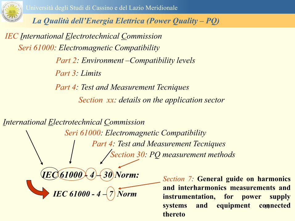
11
IEC 61000 - 4 ndash 30 Norm
Seri 61000 Electromagnetic Compatibility
International Electrotechnical Commission
Part 4 Test and Measurement Tecniques
Section 30 PQ measurement methods
IEC 61000 - 4 ndash 7 Norm
Section 7 General guide on harmonics
and interharmonics measurements and
instrumentation for power supply
systems and equipment connected
thereto
Part 2 Environment ndashCompatibility levels
Seri 61000 Electromagnetic Compatibility
IEC International Electrotechnical Commission
Section xx details on the application sector
Part 3 Limits
Part 4 Test and Measurement Tecniques
Universitagrave degli Studi di Cassino e del Lazio Meridionale
La Qualitagrave dellrsquoEnergia Elettrica (Power Quality ndash PQ)
12
EN 501602010-07 Caratteristiche della tensione fornita dalle reti pubbliche di distribuzione
dellrsquoenergia elettrica
Descrive e specifica le caratteristiche principali della tensione ai terminali di
alimentazione di un utente della rete pubblica in bassa media e alta tensione in corrente
alternata in normali condizioni di esercizio Essa descrive i limiti o valori entro i quali le
caratteristiche della tensione possono essere attesi ai punti di alimentazione da reti elettriche
pubbliche europee e non descrive la situazione media sperimentata da un singolo utente di rete
Le caratteristiche della tensione fornite nella presente Norma non sono utilizzabili ai fini dei
limiti di EMC o di disturbi condotti nella rete pubblica Esse non sono utilizzabili ai fini di
prescrizioni nelle norme di prodotto o nelle norme per impianti
Normativa di riferimento
Universitagrave degli Studi di Cassino e del Lazio Meridionale
La Qualitagrave dellrsquoEnergia Elettrica (Power Quality ndash PQ)
13
Nel dettaglio la norma EN 50160 definisce i seguenti parametri
1 Frequenza nominale della tensione fornita
2 Ampiezza della tensione di alimentazione
3 Variazioni della tensione di alimentazione
4 Flicker - variazioni rapide della tensione
5 Buchi di tensione
6 Interruzioni della tensione di alimentazione
7 Squilibrio della tensione di alimentazione
8 Tensioni armoniche THD e fino al 25deg ordine
Universitagrave degli Studi di Cassino e del Lazio Meridionale
La Qualitagrave dellrsquoEnergia Elettrica (Power Quality ndash PQ)
14
Si specifica che qualora lrsquoazienda distributrice installi un registratore
della qualitagrave delle caratteristiche della tensione diverse dalle
interruzioni senza preavviso lunghe brevi e transitorie lo strumento
deve essere conforme alla norma tecnica EN 61000-4-30
Richiami nella delibera 042004
dellAUTORITA PER LENERGIA ELETTRICA E IL GAS
Il 30 gennaio 2004 con delibera 404 lrsquoautoritagrave dellrsquoenergia ha indicato tra i vari
argomenti trattati i criteri di misura delle qualitagrave della tensione
Nellrsquoarticolo 39 (pagina 29) viene indicato nel punto 391 e 2 che per la
registrazione di interruzioni senza preavviso lunghe brevi e transitorie occorre
utilizzare un registratore conforme alla CEI EN 50160 In questo caso lo strumento
registratore dice quando e per quanto si ha unrsquointerruzione del servizio ma a tutti gli
effetti NON EFFETTUA UNrsquoOSSERVAZIONE QUALITATIVA dei parametri
Universitagrave degli Studi di Cassino e del Lazio Meridionale
La Qualitagrave dellrsquoEnergia Elettrica (Power Quality ndash PQ)
15
Universitagrave degli Studi di Cassino e del Lazio Meridionale
La Qualitagrave dellrsquoEnergia Elettrica (Power Quality ndash PQ)
16
17
Universitagrave degli Studi di Cassino e del Lazio Meridionale
La Qualitagrave dellrsquoEnergia Elettrica (Power Quality ndash PQ)
CURVA DI TOLLERANZA AI DISTURBI
18
Caratteristiche dellrsquoalimentazione a bassa tensione
Universitagrave degli Studi di Cassino e del Lazio Meridionale
La Qualitagrave dellrsquoEnergia Elettrica (Power Quality ndash PQ)
19
Caratteristiche dellrsquoalimentazione a bassa tensione
Frequenza nominale
La frequenza nominale della tensione fornita deve essere di 50 Hz In condizioni normali
di esercizio il valore medio misurato nellrsquointervallo di 10 secondi deve essere
Per i sistemi con collegamento sincrono ad un sistema interconnesso
1 50 Hz plusmn 1 durante il 95 di un anno
2 50 Hz +4 - 6 durante il 100 di un anno
Per i sistemi senza collegamento sincrono ad un sistema interconnesso
1 50 Hz plusmn 2 durante il 95 di un anno
2 50 Hz plusmn 15 durante il 100 di un anno
Universitagrave degli Studi di Cassino e del Lazio Meridionale
La Qualitagrave dellrsquoEnergia Elettrica (Power Quality ndash PQ)
20
Caratteristiche dellrsquoalimentazione a bassa tensione
Universitagrave degli Studi di Cassino e del Lazio Meridionale
La Qualitagrave dellrsquoEnergia Elettrica (Power Quality ndash PQ)
21
Caratteristiche dellrsquoalimentazione a bassa tensione
Universitagrave degli Studi di Cassino e del Lazio Meridionale
La Qualitagrave dellrsquoEnergia Elettrica (Power Quality ndash PQ)
22
Variazioni della tensione di alimentazione (variazioni lente)
Le variazioni lente sono deviazioni ldquomedierdquo dal valore nominale dellrsquoampiezza della
tensione di consegna entro una fascia predefinita (per esempio del plusmn10) rispetto alla
tensione dichiarata
CAUSE variazione lenta dei carichi e dalla corrispondente azione di regolazione effettuata dai
variatori sotto carico dei trasformatori
Universitagrave degli Studi di Cassino e del Lazio Meridionale
La Qualitagrave dellrsquoEnergia Elettrica (Power Quality ndash PQ)
23
Variazioni della tensione di alimentazione (variazioni rapide)
Le variazioni rapide sono abbassamenti (o aumenti) bruschi di qualche percento della
tensione preesistente generalmente seguiti se abbassamenti da un ritorno (a rampa o di
altra forma) ad un valore intermedio tra quello preesistente e tra il minimo raggiunto
CAUSE commutazione dei carichi (partenza motori in particolare) funzionamento di carichi
con ciclo operativo particolarmente variabile e in qualche caso da manovre in rete (linee
trasformatori condensatori ecc)
Universitagrave degli Studi di Cassino e del Lazio Meridionale
La Qualitagrave dellrsquoEnergia Elettrica (Power Quality ndash PQ)
24
Flicker Il flicker egrave originato dalla fluttuazione della tensione Si definisce fluttuazione di tensione una
serie di variazioni rapide (uguali o diverse) della tensione
Fluttuazioni di tensione che presentano frequenze di modulazione del 50 Hz comprese tra 05 e
40 Hz danno origine al fenomeno del flicker (sfarfallio) ovvero della sensazione visiva
provocata dalle fluttuazioni dellrsquointensitagrave di illuminazione delle lampade
I suoi principali effetti sullrsquouomo possono essere mal di testa irritabilitagrave e fastidio agli occhi
Universitagrave degli Studi di Cassino e del Lazio Meridionale
La Qualitagrave dellrsquoEnergia Elettrica (Power Quality ndash PQ)
25
Universitagrave degli Studi di Cassino e del Lazio Meridionale
La Qualitagrave dellrsquoEnergia Elettrica (Power Quality ndash PQ)
26
La Qualitagrave dellrsquoEnergia Elettrica (Power Quality ndash PQ)
Universitagrave degli Studi di Cassino e del Lazio Meridionale
La Qualitagrave dellrsquoEnergia Elettrica (Power Quality ndash PQ)
27
Universitagrave degli Studi di Cassino e del Lazio Meridionale
La Qualitagrave dellrsquoEnergia Elettrica (Power Quality ndash PQ)
28
Universitagrave degli Studi di Cassino e del Lazio Meridionale
La Qualitagrave dellrsquoEnergia Elettrica (Power Quality ndash PQ)
29
Universitagrave degli Studi di Cassino e del Lazio Meridionale
La Qualitagrave dellrsquoEnergia Elettrica (Power Quality ndash PQ)
30
Universitagrave degli Studi di Cassino e del Lazio Meridionale
La Qualitagrave dellrsquoEnergia Elettrica (Power Quality ndash PQ)
31
Universitagrave degli Studi di Cassino e del Lazio Meridionale
La Qualitagrave dellrsquoEnergia Elettrica (Power Quality ndash PQ)
32
Buchi di tensione Riduzione temporanea della tensione in un punto della rete elettrica sotto una determinata
soglia Se durante un buco la tensione scende sotto una soglia di interruzione lrsquoevento egrave
considerato essere sia un buco che unrsquointerruzione
CAUSE I buchi di tensione sono generalmente dovuti a guasti che sopravvengono negli
impianti utilizzatori o nel sistema di distribuzione pubblico Possono dipendere anche variazioni
di carico lungo la linea
Universitagrave degli Studi di Cassino e del Lazio Meridionale
La Qualitagrave dellrsquoEnergia Elettrica (Power Quality ndash PQ)
33
Interruzioni della tensione di alimentazione Condizione in cui la tensione ad un terminale della rete egrave inferiore allrsquo1 della tensione
nominale per una durata fino a tre minuti (brevi) o maggiori di 3 minuti (lunghe)
Universitagrave degli Studi di Cassino e del Lazio Meridionale
La Qualitagrave dellrsquoEnergia Elettrica (Power Quality ndash PQ)
34
Sovratensioni temporanee alla frequenza di rete fra fasi e terra Le sovratensioni sono sopraelevazioni della tensione conseguenti a modificazioni dello
stato elettrico della rete elettrica
Universitagrave degli Studi di Cassino e del Lazio Meridionale
La Qualitagrave dellrsquoEnergia Elettrica (Power Quality ndash PQ)
35
Armoniche Le armoniche sono tensioni o correnti sinusoidali con frequenza pari ad un multiplo intero
(ordine) della frequenza fondamentale di funzionamento del sistema elettrico la cui
presenza determina una distorsione della forma drsquoonda della tensione di alimentazione
CAUSE In piccola parte dal sistema stesso (trasformatori etc) e per la maggior parte da
apparecchi utilizzatori carichi commutati elettronicamente raddrizzatori convertitori regolatori
in AC cicloconvertitori ecc carichi con caratteristiche non lineari apparecchiature a
saturazione magnetica lampade a scarica forni ad arco saldatrici ad arco trasformatori ecc
bull carichi inseriti e disinseriti da organi di manovra condensatori filtri e motori a induzione
Universitagrave degli Studi di Cassino e del Lazio Meridionale
La Qualitagrave dellrsquoEnergia Elettrica (Power Quality ndash PQ)
36
Armoniche di tensione e corrente ndash Problemi
Vi sono diversi ambiti causati dalle armoniche
bull problemi causati da armoniche di corrente
1048707 sovraccarico del neutro
1048707 aumento delle perdite nei trasformatori
1048707 interventi intempestivi degli interruttori automatici
1048707 aumento dellrsquoeffetto pelle
bull problemi causati da armoniche di tensione
1048707 deformazione della tensione
1048707 disturbi nella coppia dei motori ad induzione
1048707 rumore al passaggio per lo zero
bull problemi causati quando le armoniche di corrente raggiungono lrsquoalimentazione
Universitagrave degli Studi di Cassino e del Lazio Meridionale
La Qualitagrave dellrsquoEnergia Elettrica (Power Quality ndash PQ)
37
38
Universitagrave degli Studi di Cassino e del Lazio Meridionale
La Qualitagrave dellrsquoEnergia Elettrica (Power Quality ndash PQ)
39
Strumentazione ldquohand heldrdquo con display
Universitagrave degli Studi di Cassino e del Lazio Meridionale
La Qualitagrave dellrsquoEnergia Elettrica (Power Quality ndash PQ)
40
Strumentazione ldquohand heldrdquo con display
Universitagrave degli Studi di Cassino e del Lazio Meridionale
La Qualitagrave dellrsquoEnergia Elettrica (Power Quality ndash PQ)
41
Strumentazione da registrazione
Universitagrave degli Studi di Cassino e del Lazio Meridionale
La Qualitagrave dellrsquoEnergia Elettrica (Power Quality ndash PQ)
42
Schema di principio ndash 61000-4-30 copy IEC2008
The electrical quantity to be measured may be either directly accessible as is
generally the case in low-voltage systems or accessible via measurement
transducers
An instrument may include the whole measurement chain In this standard the
normative part does not consider the measurement transducers external to the
instrument and their associated uncertainty
Universitagrave degli Studi di Cassino e del Lazio Meridionale
La Qualitagrave dellrsquoEnergia Elettrica (Power Quality ndash PQ)
43
Universitagrave degli Studi di Cassino Corso di Fondamenti di Misure
La Qualitagrave dellrsquoEnergia Elettrica (Power Quality ndash PQ)
Classi dei metodi di misura - 61000-4-30 copy IEC2008
For each class measurement methods and appropriate performance requirements
are included
Sono definite tre classi A S e B
Class A
This class is used where precise measurements are necessary for example for contractual
applications that may require resolving disputes verifying compliance with standards etc
Any measurements of a parameter carried out with two different instruments complying with
the requirements of Class A when measuring the same signals will produce matching results
within the specified uncertainty for that parameter
Class S
This class is used for statistical applications such as surveys or power quality assessment
possibly with a limited subset of parameters Although it uses equivalent intervals of
measurement as class A the class S processing requirements are lower
Class B
This class is defined in order to avoid making many existing instruments designs obsolete
NOTE Class B methods are not recommended for new designs Readers are advised that Class B may be removed in a
future Edition of this standard
44
Classi dei metodi di misura - 61000-4-30 copy IEC2008
Measurement aggregation over time intervals
CLASS A
The basic measurement time interval for parameter magnitudes (supply voltage harmonics
interharmonics and unbalance) shall be a 10-cycle time interval for a 50 Hz power system
or 12-cycle time interval for a 60 Hz power system
The 1012-cycle measurement shall be re-synchronized at every RTC 10 min tick
The 1012-cycle values are then aggregated over 3 additional intervals
ndash 150180-cycle interval (150 cycles for 50 Hz nominal or 180 cycles for 60 Hz nominal)
ndash 10 min interval
ndash 2 h interval
CLASS S
Same time intervals as Class A
CLASS B
The manufacturer shall specify the number and duration of aggregation time intervals
Universitagrave degli Studi di Cassino e del Lazio Meridionale
La Qualitagrave dellrsquoEnergia Elettrica (Power Quality ndash PQ)
45
Universitagrave degli Studi di Cassino e del Lazio Meridionale
La Qualitagrave dellrsquoEnergia Elettrica (Power Quality ndash PQ)
46
Universitagrave degli Studi di Cassino e del Lazio Meridionale
La Qualitagrave dellrsquoEnergia Elettrica (Power Quality ndash PQ)
Class A
The 10-min aggregated value shall be tagged with the absolute time (for
example 01H1000) The time tag is the time at the conclusion of the 10-min
aggregation
The data for the 10-min time interval shall be aggregated from 1012-cycle time
intervals
Each 10-minute interval shall begin on a UTC 10-min tick The 10-min tick is
also used to re-synchronize the 1012-cycle intervals and the 150180-cycle
intervals
The final 1012-cycle interval(s) in a 10-min aggregation period will typically
overlap in time with the UTC 10-min clock tick Any overlapping 1012-cycle
interval (Overlap 1 in Figure 2) is included in the aggregation of the previous
10-min interval
47
Universitagrave degli Studi di Cassino e del Lazio Meridionale
La Qualitagrave dellrsquoEnergia Elettrica (Power Quality ndash PQ)
48
Universitagrave degli Studi di Cassino e del Lazio Meridionale
La Qualitagrave dellrsquoEnergia Elettrica (Power Quality ndash PQ)
49
Classi dei metodi di misura - 61000-4-30 copy IEC2008
Real time clock (RTC) uncertainty
Sono definite le specifiche per le 3 classi
Flagging concept
During a dip swell or interruption the measurement algorithm for other
parameters (for example frequency measurement) might produce an unreliable
value The flagging concept therefore avoids counting a single event more than
once in different parameters (for example counting a single dip as both a dip and a
frequency variation) and indicates that an aggregated value might be unreliable
Universitagrave degli Studi di Cassino e del Lazio Meridionale
La Qualitagrave dellrsquoEnergia Elettrica (Power Quality ndash PQ)
50
Classi dei metodi di misura - 61000-4-30 copy IEC2008
Power quality parameters - INDICES
Per ogni parametro viene suggerito il metodo di misura per le tre classi e
(soprattutto) le caratteristiche di precisione Per alcuni parametri rimanda a
specifiche norme (ad esempio Flicker e Armonicheinterarmoniche)
Esempio - Power frequency Class A
The frequency reading shall be obtained every 10 s As power frequency may not be exactly 50 Hz or 60
Hz within the 10 s time clock interval the number of cycles may not be an integer number The
fundamental frequency output is the ratio of the number of integral cycles counted during the 10 s time
clock interval divided by the cumulative duration of the integer cycles Before each assessment
harmonics and interharmonics shall be attenuated to minimize the effects of multiple zero crossings
The measurement time intervals shall be non-overlapping Individual cycles that overlap the 10 s time
clock are discarded Each 10 s interval shall begin on an absolute 10 s time clock with uncertainty as
defined in 46
Other techniques that provide equivalent results such as convolution are acceptable
Class S Same as class A
Class B The manufacturer shall specify the process used for frequency measurement
Universitagrave degli Studi di Cassino e del Lazio Meridionale
La Qualitagrave dellrsquoEnergia Elettrica (Power Quality ndash PQ)
51
Classi dei metodi di misura - 61000-4-30 copy IEC2008
Power quality parameters - INDICES
Per ogni parametro viene suggerito il metodo di misura per le tre classi e
(soprattutto) le caratteristiche di precisione Per alcuni parametri rimanda a
specifiche norme (ad esempio Flicker e Armonicheinterarmoniche)
Esempio - Power frequency
Measurement uncertainty and measuring range
ndash Class A
Under the conditions described in 61 the measurement uncertainty shall not exceed
plusmn10 mHz over the measuring ranges 425 Hz ~ 575 Hz 51 Hz ~ 69 Hz
ndash Class S
Under the conditions described in 61 the measurement uncertainty shall not exceed
plusmn50 mHz over the measuring ranges 425 Hz ~ 575 Hz 51 Hz ~ 69 Hz
ndash Class B
The manufacturer shall specify the uncertainty over the measuring ranges 425 Hz ~
575 Hz 51 Hz ~ 69 Hz
Universitagrave degli Studi di Cassino e del Lazio Meridionale
La Qualitagrave dellrsquoEnergia Elettrica (Power Quality ndash PQ)
52
Magnitude of the supply voltage
Measurement method
ndash Class A
The measurement shall be the rms value of the voltage magnitude over
a 10-cycle time interval for 50 Hz power system or 12-cycle time
interval for 60 Hz power system Every 1012-cycle interval shall be
contiguous and not overlapping with adjacent 1012-cycle intervals
except as shown as Overlap 1 in Figure 2
NOTE 1 This specific measurement method is used for quasi-stationary signals and is
not used for the detection and measurement of disturbances dips swells voltage
interruptions and transients
NOTE 2 The rms value includes by definition harmonics interharmonics mains
signalling etc
- Class S same as Class A
Universitagrave degli Studi di Cassino e del Lazio Meridionale
La Qualitagrave dellrsquoEnergia Elettrica (Power Quality ndash PQ)
53
Magnitude of the supply voltage
Measurement uncertainty and measuring range
ndash Class A
Under the conditions described in Clause 6 the measurement uncertainty
shall not exceed plusmn01 of Udin over the range of 10 ~ 150 of Udin
ndash Class S
Under the conditions described in Clause 6 the measurement uncertainty
shall not exceed plusmn05 of Udin over the range of 20 ~ 120 of Udin
Universitagrave degli Studi di Cassino e del Lazio Meridionale
La Qualitagrave dellrsquoEnergia Elettrica (Power Quality ndash PQ)
54
Supply voltage dips and swells
Measurement method
ndash Class A
The basic measurement Urms of a voltage dip and swell shall be the
Urms(frac12) on each measurement channel (see Clause 322)
The cycle duration for Urms(frac12) depends on the frequency The
frequency might be determined by the last non-flagged power frequency
measurement (see Clause 47 and Clause 51) or by any other method
that yields the uncertainty requirements of Clause 6
NOTE 1 The Urms(frac12) value includes by definition harmonics interharmonics mains
signalling voltage etc
NOTE 2 It is important to avoid loss of data when dips and swells occur in a rapid
sequence (for example three events in one second with up to one minute between
sequences may occur when a recloser operates into a sustained fault) If during a rapid
burst the dipswell event characteristics cannot be recorded then a count of events may
be useful
Universitagrave degli Studi di Cassino e del Lazio Meridionale
La Qualitagrave dellrsquoEnergia Elettrica (Power Quality ndash PQ)
55
Supply voltage dips and swells
Detection and evaluation of a voltage dip
Voltage dip detection
The dip threshold is a percentage of either Udin or the sliding voltage
reference Usr (see 525 544) The user shall declare the reference
voltage in use
NOTE ndash On single-phase systems a voltage dip begins when the Urms voltage falls
below the dip threshold and ends when the Urms voltage is equal to or above the dip
threshold plus the hysteresis voltage
ndash On polyphase systems a dip begins when the Urms voltage of one or more channels is
below the dip threshold and ends when the Urms voltage on all measured channels is
equal to or above the dip threshold plus the hysteresis voltage
The dip threshold and the hysteresis voltage are both set by the user according to the
use
Universitagrave degli Studi di Cassino e del Lazio Meridionale
La Qualitagrave dellrsquoEnergia Elettrica (Power Quality ndash PQ)
56
Calculation of a sliding reference voltage
The sliding reference voltage implementation is optional not mandatory
If a sliding reference is chosen for voltage dip or swell detection this
shall be calculated using a first-order filter with a 1-min time constant
This filter is given by
Usr(n) = 09967 times Usr(nndash1) + 00033 times U(1012)rms
where
Usr(n) is the present value of the sliding reference voltage
Usr(nndash1) is the previous value of the sliding reference voltage and
U(1012)rms is the most recent 1012-cycle rms value
When the measurement is started the initial value of the sliding reference voltage is set
to the declared input voltage The sliding reference voltage is updated every 1012-
cycles If a 1012-cycle value is flagged the sliding reference voltage is not updated
and the previous value is used
Universitagrave degli Studi di Cassino e del Lazio Meridionale
La Qualitagrave dellrsquoEnergia Elettrica (Power Quality ndash PQ)
57
Supply voltage dips and swells
Voltage dip evaluation
A voltage dip is characterized by a pair of data either residual voltage
(Ures) or depth and duration
ndash the residual voltage of a voltage dip is the lowest Urms(frac12) value
measured on any channel during the dip
ndash the depth is the difference between the reference voltage (either Udin
or Usr) and the residual voltage It is generally expressed in percentage
of the reference voltage
NOTE 1 During the dip it may be useful to also record the lowest Urms(frac12) on each
channel in addition to the residual voltage of the dip The duration spent below the dip
threshold on each channel may also be useful
Universitagrave degli Studi di Cassino e del Lazio Meridionale
La Qualitagrave dellrsquoEnergia Elettrica (Power Quality ndash PQ)
58
Supply voltage dips and swells
Voltage dip evaluation
NOTE 2 If voltage waveforms are recorded before during and after a
dip useful information about phase angle changes may be available in
the recorded data
The start time of a dip shall be time stamped with the time of the start of
the Urms of the channel that initiated the event and the end time of the
dip shall be the time stamped with the time of the end of the Urms that
ended the event as defined by the threshold plus the hysteresis
The duration of a voltage dip is the time difference between the start
time and the end time of the voltage dip
Universitagrave degli Studi di Cassino e del Lazio Meridionale
La Qualitagrave dellrsquoEnergia Elettrica (Power Quality ndash PQ)
59
Supply voltage dips and swells
Residual voltage and swell voltage magnitude measurement
uncertainty
ndash Class A
The measurement uncertainty shall not exceed plusmn02 of Udin
ndash Class S
The measurement uncertainty shall not exceed plusmn10 of Udin
Universitagrave degli Studi di Cassino e del Lazio Meridionale
La Qualitagrave dellrsquoEnergia Elettrica (Power Quality ndash PQ)
60
Schema di principio ndash 61000-4-7 copy IEC2002
Universitagrave degli Studi di Cassino e del Lazio Meridionale
La Qualitagrave dellrsquoEnergia Elettrica (Power Quality ndash PQ)
61
Universitagrave degli Studi di Cassino e del Lazio Meridionale
La Qualitagrave dellrsquoEnergia Elettrica (Power Quality ndash PQ)
62
Universitagrave degli Studi di Cassino e del Lazio Meridionale
La Qualitagrave dellrsquoEnergia Elettrica (Power Quality ndash PQ)
63
Inter-Armoniche Le inter-armoniche sono tensioni o correnti sinusoidali con frequenza diversa da un
multiplo intero della fondamentale la cui presenza determina una distorsione
(modulazione) della forma donda della tensione di alimentazione
CAUSE dai carichi che assorbono correnti inter-armoniche
- carichi commutati elettronicamente convertitori cascata subsincrona cicloconvertitori regolatori con
controllo a pacchetti di cicli ecc
- carichi con caratteristiche non lineari eo non stazionarie forni ad arco saldatrici ad arco ecc
Universitagrave degli Studi di Cassino e del Lazio Meridionale
La Qualitagrave dellrsquoEnergia Elettrica (Power Quality ndash PQ)
64
Universitagrave degli Studi di Cassino e del Lazio Meridionale
La Qualitagrave dellrsquoEnergia Elettrica (Power Quality ndash PQ)
Un porsquo di esempi e
consigli praticihellip
65
0V
50V
100V
150V
200V
250V
300V
350V
0ms 5ms 10ms 15ms 20ms
t
u
0A
1A
2A
3A
i
0V
50V
100V
150V
200V
250V
300V
350V
0ms 5ms 10ms 15ms 20ms
t
u
0A
1A
2A
3A
i
0V
50V
100V
150V
200V
250V
300V
350V
0ms 5ms 10ms 15ms 20ms
t
u
0A
1A
2A
3A
i
gleichgerichtete
Netzspannung
Kondensator-
spannung
gleichgerichteter
Netzstrom
The situation
today
bull Computed current and voltage profiles when a
230 V 58 W fluorescent lamp with an old-style
electronic ballast is driven on the phase wire of
a typical power distribution system
System voltage 230 V
System frequency 50 Hz
Source resistance 500 mW
Longitudinal induction 904 microH
System impedance 575 mW
Mean dc current 180 mA
Smoothing capacitance220 microF
66
And what about electronic ballasts that are rated over 25W
Introduce electronic power factor correction (PFC)
0V
20V
40V
60V
80V
100V
120V
140V
160V
180V
200V
220V
0deg 15deg 30deg 45deg
u
00A
03A
06A
09A
12A
i
67
Though todayrsquos ballasts are better if
rated gt25 W bull Only
the
small
ones
continu
e to
pollute
just like
PCs
TV sets
do
68
This leads to a number of
previously unknown effects bull 1 Deformed voltage curves
bull 2 Huge inrush current peaks
bull 3 Instrument dependent measured parameters
bull 4 Increased loading of phase conductors
bull 5 Loading and overloading of the neutral conductor
bull 6 Overheating and start-up problems of induction motors
bull 7 Additional stray losses in transformers
bull 8 Repercussions of generators upon the mains
bull 9 Influence of capacitors repercussions upon the mains
and four additional complications in TN-C systems
10 Stray currents in equipotential bonding system magnetic fields
11 Contamination of data streams by stray currents
12 Stray currents in the earthing system corrosion damage
13 Lightning currents in devices and equipment
69
1 Deformed voltage curves
bull in theory
-350V
-300V
-250V
-200V
-150V
-100V
-50V
0V
50V
100V
150V
200V
250V
300V
350V
0 5 10 15 20
t ms
u
System voltage profile when driving
a single-phase load comprising
twenty 58 W energy-saver lamps in
parallel on a typical 230 V power
system
70
and in practice
bull An actual
current profile
bull
bull and
bull a voltage profile
bull
bull recorded in a large storage
dispatch and administrative
building
71
at home or in industrial environments
bull
bull Television 40
W
bull 200 Vdiv 2
Adiv
bull 5 msdiv
Harmonic
spectrum
Frequency
converter
50 Adiv
Phase currents
I1=I2=I3=160 A
IN=295 A
5 msdiv
72
Every periodic waveform can be written
as the infinite sum of sinusoidal waves
-175
-150
-125
-100
-75
-50
-25
0
25
50
75
100
125
150
175
0 5 10 15 20
t ms
i
mA
itot
i1
Synthesis of a triangular current profile 100mA
Content fundamental I = 99 mA Isup2 = 9855 mAsup2
Sum of squares Isup2 = 9855 mAsup2
Root of sum = RMS value I = 99 mA
-175
-150
-125
-100
-75
-50
-25
0
25
50
75
100
125
150
175
0 5 10 15 20
t ms
i
mA
itot
i1
i3
Synthesis of a triangular current profile 100mA
Content fundamental I = 99 mA Isup2 = 9855 mAsup2
Cont 3 rd harmonic I = -11 mA Isup2 = 122 mAsup2
Sum of squares Isup2 = 9977 mAsup2
Root of sum = RMS value I = 100 mA
-175
-150
-125
-100
-75
-50
-25
0
25
50
75
100
125
150
175
0 5 10 15 20
t ms
i
mA
itot
i1
i3
i5
Synthesis of a triangular current profile 100mA
Content fundamental I = 99 mA Isup2 = 9855 mAsup2
Cont 3 rd harmonic I = -11 mA Isup2 = 122 mAsup2
Cont 5 th harmonic I = 4 mA Isup2 = 16 mAsup2
Sum of squares Isup2 = 9993 mAsup2
Root of sum = RMS value I = 100 mA
-175
-150
-125
-100
-75
-50
-25
0
25
50
75
100
125
150
175
0 5 10 15 20
t ms
i
mA
itot
i1
i3
i5
i7
Synthesis of a triangular current profile 100mA
Content fundamental I = 99 mA Isup2 = 9855 mAsup2
Cont 3 rd harmonic I = -11 mA Isup2 = 122 mAsup2
Cont 5 th harmonic I = 4 mA Isup2 = 16 mAsup2
Cont 7 th harmonic I = -2 mA Isup2 = 4 mAsup2
Sum of squares Isup2 = 9997 mAsup2
Root of sum = RMS value I = 100 mA
-175
-150
-125
-100
-75
-50
-25
0
25
50
75
100
125
150
175
0 5 10 15 20
t ms
i
mA
itot i1
i3 i5
i7 i9
Synthesis of a triangular current profile 100mA
Content fundamental I = 99 mA Isup2 = 9855 mAsup2
Cont 3 rd harmonic I = -11 mA Isup2 = 122 mAsup2
Cont 5 th harmonic I = 4 mA Isup2 = 16 mAsup2
Cont 7 th harmonic I = -2 mA Isup2 = 4 mAsup2
Cont 9 th harmonic I = 1 mA Isup2 = 2 mAsup2
Sum of squares Isup2 = 9998 mAsup2
Root of sum = RMS value I = 100 mA
-175
-150
-125
-100
-75
-50
-25
0
25
50
75
100
125
150
175
0 5 10 15 20
t ms
i
mA
itot i1
i3 i5
i7 i9
i11
Synthesis of a triangular current profile 100mA
Content fundamental I = 99 mA Isup2 = 9855 mAsup2
Cont 3 rd harmonic I = -11 mA Isup2 = 122 mAsup2
Cont 5 th harmonic I = 4 mA Isup2 = 16 mAsup2
Cont 7 th harmonic I = -2 mA Isup2 = 4 mAsup2
Cont 9 th harmonic I = 1 mA Isup2 = 2 mAsup2
Cont 11 th harmonic I = -1 mA Isup2 = 1 mAsup2
Sum of squares Isup2 = 9999 mAsup2
Root of sum = RMS value I = 100 mA
-175
-150
-125
-100
-75
-50
-25
0
25
50
75
100
125
150
175
0 5 10 15 20
t ms
i
mA
itot i1
i3 i5
i7 i9
i11 i13
Synthesis of a triangular current profile 100mA
Content fundamental I = 99 mA Isup2 = 9855 mAsup2
Cont 3 rd harmonic I = -11 mA Isup2 = 122 mAsup2
Cont 5 th harmonic I = 4 mA Isup2 = 16 mAsup2
Cont 7 th harmonic I = -2 mA Isup2 = 4 mAsup2
Cont 9 th harmonic I = 1 mA Isup2 = 2 mAsup2
Cont 11 th harmonic I = -1 mA Isup2 = 1 mAsup2
Cont 13 th harmonic I = 1 mA Isup2 = 0 mAsup2
Sum of squares Isup2 = 9999 mAsup2
Root of sum = RMS value I = 100 mA
-175
-150
-125
-100
-75
-50
-25
0
25
50
75
100
125
150
175
0 5 10 15 20
t ms
i
mA
itot i1
i3 i5
i7 i9
i11 i13
i15
Synthesis of a triangular current profile 100mA
Content fundamental I = 99 mA Isup2 = 9855 mAsup2
Cont 3 rd harmonic I = -11 mA Isup2 = 122 mAsup2
Cont 5 th harmonic I = 4 mA Isup2 = 16 mAsup2
Cont 7 th harmonic I = -2 mA Isup2 = 4 mAsup2
Cont 9 th harmonic I = 1 mA Isup2 = 2 mAsup2
Cont 11 th harmonic I = -1 mA Isup2 = 1 mAsup2
Cont 13 th harmonic I = 1 mA Isup2 = 0 mAsup2
Cont 15 th harmonic I = 0 mA Isup2 = 0 mAsup2
Sum of squares Isup2 = 10000 mAsup2
Root of sum = RMS value I = 100 mA
-175
-150
-125
-100
-75
-50
-25
0
25
50
75
100
125
150
175
0 5 10 15 20
t ms
i
mA
itot i1
i3 i5
i7 i9
i11 i13
i15 i17
Synthesis of a triangular current profile 100mA
Content fundamental I = 99 mA Isup2 = 9855 mAsup2
Cont 3 rd harmonic I = -11 mA Isup2 = 122 mAsup2
Cont 5 th harmonic I = 4 mA Isup2 = 16 mAsup2
Cont 7 th harmonic I = -2 mA Isup2 = 4 mAsup2
Cont 9 th harmonic I = 1 mA Isup2 = 2 mAsup2
Cont 11 th harmonic I = -1 mA Isup2 = 1 mAsup2
Cont 13 th harmonic I = 1 mA Isup2 = 0 mAsup2
Cont 15 th harmonic I = 0 mA Isup2 = 0 mAsup2
Cont 17 th harmonic I = 0 mA Isup2 = 0 mAsup2
Sum of squares Isup2 = 10000 mAsup2
Root of sum = RMS value I = 100 mA
73
whose frequencies called harmonics are
integer multiples of the fundamental frequency
-175
-150
-125
-100
-75
-50
-25
0
25
50
75
100
125
150
175
0 5 10 15 20
t ms
i
mA
itot
i1
Synthesis of a rectangular current profile 100mA
Content fundamental I = 90 mA Isup2 = 8106 mAsup2
Sum of squares Isup2 = 8106 mAsup2
Root of sum = RMS value I = 90 mA
-175
-150
-125
-100
-75
-50
-25
0
25
50
75
100
125
150
175
0 5 10 15 20
t ms
i
mA
itot
i1
i3
Synthesis of a rectangular current profile 100mA
Content fundamental I = 90 mA Isup2 = 8106 mAsup2
Cont 3 rd harmonic I = 30 mA Isup2 = 901 mAsup2
Sum of squares Isup2 = 9006 mAsup2
Root of sum = RMS value I = 95 mA
-175
-150
-125
-100
-75
-50
-25
0
25
50
75
100
125
150
175
0 5 10 15 20
t ms
i
mA
itot
i1
i3
i5
Synthesis of a rectangular current profile 100mA
Content fundamental I = 90 mA Isup2 = 8106 mAsup2
Cont 3 rd harmonic I = 30 mA Isup2 = 901 mAsup2
Cont 5 th harmonic I = 18 mA Isup2 = 324 mAsup2
Sum of squares Isup2 = 9331 mAsup2
Root of sum = RMS value I = 97 mA
-175
-150
-125
-100
-75
-50
-25
0
25
50
75
100
125
150
175
0 5 10 15 20
t ms
i
mA
itot
i1
i3
i5
i7
Synthesis of a rectangular current profile 100mA
Content fundamental I = 90 mA Isup2 = 8106 mAsup2
Cont 3 rd harmonic I = 30 mA Isup2 = 901 mAsup2
Cont 5 th harmonic I = 18 mA Isup2 = 324 mAsup2
Cont 7 th harmonic I = 13 mA Isup2 = 165 mAsup2
Sum of squares Isup2 = 9496 mAsup2
Root of sum = RMS value I = 97 mA
-175
-150
-125
-100
-75
-50
-25
0
25
50
75
100
125
150
175
0 5 10 15 20
t ms
i
mA
itot i1
i3 i5
i7 i9
Synthesis of a rectangular current profile 100mA
Content fundamental I = 90 mA Isup2 = 8106 mAsup2
Cont 3 rd harmonic I = 30 mA Isup2 = 901 mAsup2
Cont 5 th harmonic I = 18 mA Isup2 = 324 mAsup2
Cont 7 th harmonic I = 13 mA Isup2 = 165 mAsup2
Cont 9 th harmonic I = 10 mA Isup2 = 100 mAsup2
Sum of squares Isup2 = 9596 mAsup2
Root of sum = RMS value I = 98 mA
-175
-150
-125
-100
-75
-50
-25
0
25
50
75
100
125
150
175
0 5 10 15 20
t ms
i
mA
itot i1
i3 i5
i7 i9
i11
Synthesis of a rectangular current profile 100mA
Content fundamental I = 90 mA Isup2 = 8106 mAsup2
Cont 3 rd harmonic I = 30 mA Isup2 = 901 mAsup2
Cont 5 th harmonic I = 18 mA Isup2 = 324 mAsup2
Cont 7 th harmonic I = 13 mA Isup2 = 165 mAsup2
Cont 9 th harmonic I = 10 mA Isup2 = 100 mAsup2
Cont 11 th harmonic I = 8 mA Isup2 = 67 mAsup2
Sum of squares Isup2 = 9663 mAsup2
Root of sum = RMS value I = 98 mA
-175
-150
-125
-100
-75
-50
-25
0
25
50
75
100
125
150
175
0 5 10 15 20
t ms
i
mA
itot i1
i3 i5
i7 i9
i11 i13
Synthesis of a rectangular current profile 100mA
Content fundamental I = 90 mA Isup2 = 8106 mAsup2
Cont 3 rd harmonic I = 30 mA Isup2 = 901 mAsup2
Cont 5 th harmonic I = 18 mA Isup2 = 324 mAsup2
Cont 7 th harmonic I = 13 mA Isup2 = 165 mAsup2
Cont 9 th harmonic I = 10 mA Isup2 = 100 mAsup2
Cont 11 th harmonic I = 8 mA Isup2 = 67 mAsup2
Cont 13 th harmonic I = 7 mA Isup2 = 48 mAsup2
Sum of squares Isup2 = 9711 mAsup2
Root of sum = RMS value I = 99 mA
-175
-150
-125
-100
-75
-50
-25
0
25
50
75
100
125
150
175
0 5 10 15 20
t ms
i
mA
itot i1
i3 i5
i7 i9
i11 i13
i15
Synthesis of a rectangular current profile 100mA
Content fundamental I = 90 mA Isup2 = 8106 mAsup2
Cont 3 rd harmonic I = 30 mA Isup2 = 901 mAsup2
Cont 5 th harmonic I = 18 mA Isup2 = 324 mAsup2
Cont 7 th harmonic I = 13 mA Isup2 = 165 mAsup2
Cont 9 th harmonic I = 10 mA Isup2 = 100 mAsup2
Cont 11 th harmonic I = 8 mA Isup2 = 67 mAsup2
Cont 13 th harmonic I = 7 mA Isup2 = 48 mAsup2
Cont 15 th harmonic I = 6 mA Isup2 = 36 mAsup2
Sum of squares Isup2 = 9747 mAsup2
Root of sum = RMS value I = 99 mA
-175
-150
-125
-100
-75
-50
-25
0
25
50
75
100
125
150
175
0 5 10 15 20
t ms
i
mA
itot i1
i3 i5
i7 i9
i11 i13
i15 i17
Synthesis of a rectangular current profile 100mA
Content fundamental I = 90 mA Isup2 = 8106 mAsup2
Cont 3 rd harmonic I = 30 mA Isup2 = 901 mAsup2
Cont 5 th harmonic I = 18 mA Isup2 = 324 mAsup2
Cont 7 th harmonic I = 13 mA Isup2 = 165 mAsup2
Cont 9 th harmonic I = 10 mA Isup2 = 100 mAsup2
Cont 11 th harmonic I = 8 mA Isup2 = 67 mAsup2
Cont 13 th harmonic I = 7 mA Isup2 = 48 mAsup2
Cont 15 th harmonic I = 6 mA Isup2 = 36 mAsup2
Cont 17 th harmonic I = 5 mA Isup2 = 28 mAsup2
Sum of squares Isup2 = 9775 mAsup2
Root of sum = RMS value I = 99 mA
74
Even far better simulations are
available free of charge at
bull wwwpowerstandardscomMcEachern
75
-4A
-3A
-2A
-1A
0A
1A
2A
3A
4A
0ms 5ms 10ms 15ms 20ms
t
i
-4A
-3A
-2A
-1A
0A
1A
2A
3A
4A
0ms 5ms 10ms 15ms 20ms
t
i
Applying the Fourier
analysis to a real PC
current does not work
directly
bull
bull but it can be
modelled by a similar
triangular curve in
which not all of the
higher harmonics
have been included
Triangular current profile of
the same amplitude and a
pulse duty cycle of 17
Input current of a PC
with monitor
76
Analysis of the model triangular waveform
-400
-350
-300
-250
-200
-150
-100
-50
0
50
100
150
200
250
300
350
400
0 5 10 15 20
t ms
iI
itot(t) L1 [A] i1(t) L1 [A]
i3(t) L1 [A] i5(t) L1 [A]
i7(t) L1 [A] i9(t) L1 [A]
i11(t) L1 [A] i13(t) L1 [A]
i15(t) L1 [A] i17(t) L1 [A]
77
M3
Harmonics
Energy
(active
power)
L1
L2
L3
N
PE
Important
bull Harmonics are created within the loads
themselves and can flow ldquoupstreamrdquo to
contaminate the power system
78
-6A
-5A
-4A
-3A
-2A
-1A
0A
1A
2A
3A
4A
5A
6A
0ms 5ms 10ms 15ms 20ms
t
i
Squared values
Without
Fundamental 502 mA 251986 mAsup2 the fundamental
3rd harmonic -479 mA 229000 mAsup2 229000 mAsup2
5th harmonic 434 mA 188595 mAsup2 188595 mAsup2
7th harmonic -374 mA 139903 mAsup2 139903 mAsup2
9th harmonic 304 mA 92527 mAsup2 92527 mAsup2
11th harmonic -232 mA 53671 mAsup2 53671 mAsup2
13th harmonic 163 mA 26600 mAsup2 26600 mAsup2
15th harmonic -104 mA 10780 mAsup2 10780 mAsup2
17th harmonic 57 mA 3299 mAsup2 3299 mAsup2
Sum of the squares 996362 mAsup2 744377 mAsup2
Root thereof 998 mAeff THD = 863 mA
What actually is THD Example shown here triangular current
profile with an rms current of 1000 mA
and a pulse duty cycle of 17
THDr (root mean square) = 863mA1000mA = 86
THDf (fundamental) = 863mA502mA = 172
79
Effect on phase-to-neutral
and phase-to-phase voltages
bull Recorded
on June
30 2002
230 p
m
bull What
was the
matter
then
bull The
soccer
final
Germany
vs
Brazil
80
The triple-N harmonics drive
a circulating current in the
delta winding of a distribution
transformer
bull but the
bull voltage harmonics
propagate into the next
low-voltage power
distribution system
81 0V
50V
100V
150V
200V
250V
300V
350V
400V
450V
500V
550V
0 10 20 30 40 50
t ms
u
0A
10A
20A
30A
40A
50A
60A
70A
80A
90A
100A
110A
120A
130A
140A
150A
i
Switching on just as supply voltage passes through zero
0V
50V
100V
150V
200V
250V
300V
350V
400V
450V
500V
550V
0 10 20 30 40 50
t ms
u
0A
10A
20A
30A
40A
50A
60A
70A
80A
90A
100A
110A
120A
130A
140A
150A
i
Switching on just as supply voltage is at its peak
2 Huge inrush current peaks
ndash in theory
82
and in practice
bull Inrush current of a
compact energy-
saver lamp and its
effect on the system
voltage (recorded at
the Technical
University of
Budapest)
bull
83
enables us to infer what
happens when run by a
normal three-phase supply
The same fluorescent lamp
with a magnetic ballast
bull The behaviour measured
when connected to
a dc supply
bull
Behaviour of a 58 W fluorescent lamp connected to a dc
supply
0
20
40
60
80
100
120
140
160
180
200
0 200 400 600 800 1000 1200
i mA
u
V
Measurement
Behaviour of a 58 W fluorescent lamp connected to a dc
supply
0
20
40
60
80
100
120
140
160
180
200
0 200 400 600 800 1000 1200
i mA
u
V
MeasurementCalculation
-350
-300
-250
-200
-150
-100
-50
0
50
100
150
200
250
300
350
0 5 10 15 20
t ms
u
V
-10
-08
-06
-04
-02
00
02
04
06
08
10
i
A
Systems voltage
Current
-350
-300
-250
-200
-150
-100
-50
0
50
100
150
200
250
300
350
0 5 10 15 20
t ms
u
V
-10
-08
-06
-04
-02
00
02
04
06
08
10
i
A
Systems voltage
Lamp voltage
Current
84
Warning ldquoCompensationrdquo is not
always what you think it is
bull Distinguish
between
bull Reactive
power
compensatio
n
aka power
factor
correction
Remedial
measure
Parallel (or
sometimes series)
compensation
using capacitors
Filter circuits
tuned to the
individual harmonic
frequencies
Harmonic
compensation
85
5 (Over)loading the neutral conductor
bull Magnetic ballast Old-style electronic ballast
-25A
-20A
-15A
-10A
-05A
00A
05A
10A
15A
20A
25A
0 5 10 15 20
t ms i
i(t) N
-25A
-20A
-15A
-10A
-05A
00A
05A
10A
15A
20A
25A
0 5 10 15 20
t ms
i
i(t) N
-25A
-20A
-15A
-10A
-05A
00A
05A
10A
15A
20A
25A
0 5 10 15 20
t ms
i
i(t) L1 i(t) L2 i(t) L3
-25A
-20A
-15A
-10A
-05A
00A
05A
10A
15A
20A
25A
0 5 10 15 20
t ms
i
i(t) L1
i(t) L2
i(t) L3
86
Adding the 3rd
harmonics
in the
neutral
wire
-150-100-50
050
100150
0deg 30deg 60deg 90deg 120deg 150deg 180deg 210deg 240deg 270deg 300deg 330deg 360deg
L1
-150-100-50
050
100150
0deg 30deg 60deg 90deg 120deg 150deg 180deg 210deg 240deg 270deg 300deg 330deg 360deg
L2
-150-100-50
050
100150
0deg 30deg 60deg 90deg 120deg 150deg 180deg 210deg 240deg 270deg 300deg 330deg 360deg
L3
-450-400-350-300-250-200-150-100-50
050
100150200250300350400450
0deg 30deg 60deg 90deg 120deg 150deg 180deg 210deg 240deg 270deg 300deg 330deg 360deg
f
iicirc
N
Physics dictates
that at any
moment in time
the phase and
neutral currents
must sum to zero
87
Effect on a three-phase ac motor
appears almost identical
bull The same motor is being
driven
simultaneously in
these three modes
homopolar system
zero-sequence system
direct system
positive-sequence system
inverse system
negative-sequence system
88
The transformer
influences the load
89
but the load also effects
the transformer
Total transformer loss is
2
)()(
nom
nomCunomFeLossI
IPPP
While total transformer loss really is
2
)(
2
)(
2
)(
nomnom
nomad
nom
nomCu
nom
nomFeLossI
I
f
fP
I
IP
U
UPP
90
6 ldquosupplementaryrdquo additional losses
in transformers
can be calculated rapidly
using the following two
simple formulae 50
2
2
1
2
11
Nn
n
nqh
I
In
I
I
e
eK
50
1
2
1
1
50
1
2
Nn
n
nNn
n
nI
IIII
where
Oh well
perhaps a practical
example is clearer
1000 compact 11W
(15VA) energy-saver
lamps powered by a
15kVA transformer
uSC=4 Pa=01PCu
Harmonics of an Osram Dulux 11W
CFL and a serial impedance of
R =291Ω amp X L=113Ω
U U sup2 I L I Lsup2 P aP Cu
n V Vsup2 mA mAsup2
1 2302 529920 485 23523 56
3 83 689 371 13764 295
5 107 1145 203 4121 245
7 43 185 53 281 33
9 11 12 30 90 17
11 23 53 38 144 42
13 10 10 15 23 09
15 06 04 15 23 12
17 11 12 15 23 15
19 05 03 09 08 07
21 05 03 13 17 18
23 06 04 08 06 08
25 04 02 06 04 05
27 06 04 08 06 11
29 04 02 05 03 05
31 03 01 05 03 06
33 03 01 05 03 06
35 03 01 04 02 05
37 03 01 04 02 05
39 03 01 03 01 03
41 01 00 03 01 04
43 02 00 02 00 02
45 01 00 02 00 02
47 01 00 02 00 02
49 01 00 01 00 01
51 01 00 01 00 01
P aP Cu = 814814
etc
etc
91
Harmonics measurement on an
Osram Dulux 11W compact
fluorescent lamp
U U sup2 I L I Lsup2 P addP Cu
n V Vsup2 mA mAsup2
1 2327 541493 489 23912 37
3 06 04 391 15288 215
5 44 194 264 6970 273
7 23 53 200 4000 307
9 01 00 192 3686 467
11 01 00 166 2756 522
13 01 00 127 1613 427
15 01 00 110 1210 426
17 01 00 102 1040 471
19 01 00 87 757 428
21 01 00 77 593 409
23 01 00 73 533 441
25 01 00 61 372 364
27 01 00 49 240 274
29 01 00 42 176 232
31 01 00 36 130 195
33 01 00 30 90 153
35 01 00 33 109 209
37 01 00 31 96 206
39 01 00 25 63 149
41 01 00 25 63 164
43 01 00 25 63 181
45 01 00 19 36 114
47 01 00 18 32 112
49 01 00 19 36 136
51 01 00 16 26 104
P aP Cu = 7017
To some extent
the transformer
protects itself
bull Always remember to
consider it
bull If the influence of the
transformer upon the load
did not exist then the
influence of the load upon
the transformer would be
nearly 9 times as high
7017
etc
etc
92
Rule of thumb Select transformers 35
larger than specification by apparent
power would require
bull This suffices to err
on the safe side
even in the worst
case and can
hardly ever be
wrong since
maximum
efficiency always
lies between 25
and 50 of rated
load
Efficiency of a 1 MVA transformer plotted against loading
985
986
987
988
989
990
991
992
993
994
0 25 50 75 100 125
Relative load h
Design with max Cu loss and min Fe loss
Design with min Cu loss and max Fe loss
1 MVA oil transformer according to HD 428
93
Measured response of an 11 W
fluorescent lamp operated with a
magnetic ballast
94
We are
dealing with
a complex
problem
bull These
effects
are not
isolated
but are
mutuall
y inter-
depende
nt
Effects 2 3 and 5 can be demonstrated
on DKIrsquos display panel
95
A conventional approximately resistive-
inductive load
mA
N L1 L2 L3
Two conventional approximately
resistive-inductive loads Three conventional approximately
resistive-inductive loads
96
A modern electronic load
mA
N
Two modern electronic loads Three modern electronic loads
L1 L2 L3
97
Discoveries on a
refurbished
junction box
System voltage
(as trigger
signal)
Current in the
earthing
conductor
between the
consumer unit
and the
bonding
busbar
98
The TN-C system that was perfectly
adequate some years ago is unable to meet
present-day requirements
-6
-4
-2
0
2
4
6
0 5 10 15 20
t ms
i
A
-350
-300
-250
-200
-150
-100
-50
0
50
100
150
200
250
300
350
0 5 10 15 20
t ms
u
V
99
ldquoTHFrdquo
(third harmonic
filter) made in
Finland
In certain situations this affordable
filter can be of help
German
version ldquoTHXrdquo
100
0Ω
5 Ω
1 0 Ω
1 5 Ω
2 0 Ω
2 5 Ω
3 0 Ω
3 5 Ω
4 0 Ω
0Hz 50Hz 100Hz 150Hz 200Hz 250Hz 300Hz
f
Z
-90deg
-75deg
-60deg
-45deg
-30deg
-15deg
0deg
15deg
30deg
45deg
60deg
75deg
90deg
φ
Reactorreactance
Capacitorreactance
Parallelimpedace
Phase angle
Data and frequency response
of the filter
bull 1320 microF
bull 875
14 mW microH
101
The filter in use
bull In a nursery running sodium vapour lamps (500 kW)
In a typical office and administrative building
102
The EMC Transformer from Switzerland
7 The effects of stray magnetic fields
in TN-C systems
bull ldquoWhen we build transformers the first thing we focus on is complying with our customersrsquo
requirements and only then on complying with standards Why Because it is customer
needs and not standards that offer real scope for product innovationrdquo
103
8 In a TN-C system problems arise from data
streams and working currents mixing
bull Others who
have drawn
attention to
this source of
data
transmission
errors include
engineering
and insurance
companies experts
consultants and many
others besides
104
9 Increased corrosive damage
bull This (once) galvanized steel strip ndash the earth
electrode of a TN-C-S system ndash was located close
to the transformer station
Side facing
transformer
station
Side facing
transformer
station
Side facing away
from transformer
station
Side facing away
from transformer
station
105
bull WRONG RIGHT
Working currents have no place
in earthing systems and
protective conductors
106
10 Lightning currents
107
Which bridge to
cross which bridge to
burn
Sometimes you just donlsquot
believe what you see
This one will soon
look rather charred
IEC 60364-5-54
54343 If from any point of the installation the neutral and protective
functions are provided by separate conductors it is not permitted to
connect the neutral conductor to any other earthed part of the
installation
108
Well then the rest is no longer a
miracle
109
110
111
Another means of (over)loading the
neutral conductor
bull dc currents
Original ldquoFakerdquo
112
and their
effects U = 2285 V
I = 92 mA
P = 182 W
S = 209 VA
Q = 103 VAr
LF = 087
cos φ = 099
U = 2243 V
I = 126 A
P = 380 W
S = 2860 VA
Q = 2830 VAr
No-load current in a
toroidal-core
transformer
200 VA
-350-300
-250-200
-150-100
-500
50
100150
200250
300350
0 10 20 30 40
t ms
u
V
-12
-10
-8
-6
-4
-2
0
2
4
6
8
10
12
i
mA
Voltage
Current
No-load current in a toroidal-core
transformer 200 VA when
running a 1500 W
hairdryer at
half-power
in parallel
-350-300
-250-200
-150-100
-500
50
100150
200250
300350
0 5 10 15 20 25 30 35 40
t ms
u
V
-6
-5
-4
-3
-2
-1
0
1
2
3
4
5
6
i
A
Voltage
Current
113
The later models donlsquot do it any more
The EN 61000-3-2 has at least managed
to put an end to this approach
Domestic appliances Max 105 A of 2nd harmonic
114
An electrical engineering wonder
dc current generates ac voltage
115
Spicing things up with a pinch of HF
electronic halogen lamp transformers
116
Decorative HF reactors
117
Current and power loss as a function of voltage
00
02
04
06
08
10
12
14
16
18
0 40 80 120 160 200 240
U V
I
A
0
20
40
60
80
100
120
PV
W
I [A]
Pv [W]
Power loss capacitor voltage
and total voltage as a function of current
0
50
100
150
200
250
300
350
400
450
000 025 050 075 100 125 150
I A
U
V
0
5
10
15
20
25
30
35
40
45
50
PV
W
Utot [V] Eff
UR [V] Eff
Pv [W]
The passive
harmonic filter
made of readily
available
components
bull is both
reliable
118
and effective
bull befor
e
bull after
119
Half the solution has already been implemented
120
And if thatrsquos not enough
bull Passive filter circuits will do it
121
So what do we need to do
bull In low-voltage power distribution systems
Do not use cables in which the neutral or protective earth conductor has a
reduced cross-section
Use only 5-core cable Do not install TN-C- or TN-C-S systems
Be generous when dimensioning conductor cross-sections This helps to
reduce line voltage drops and thus reduces the effect of current distortions on
the voltage as well as lowering energy losses (see VDE 0298 Part 100)
Generously dimensioned conductors will have no problem coping with any
future increase in demand
Only use measuring instruments that display the true root mean square value
(TRMS meters)
In medium-voltage power distribution systems
Use a varied mix of distribution transformers with different vector groups
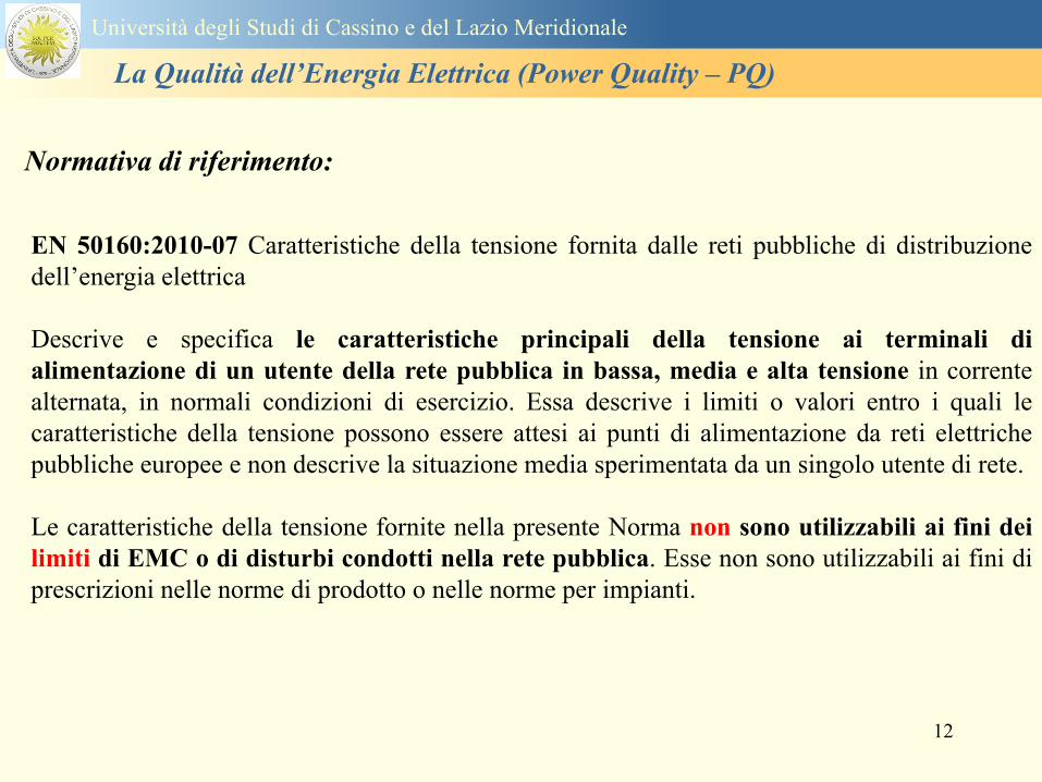
12
EN 501602010-07 Caratteristiche della tensione fornita dalle reti pubbliche di distribuzione
dellrsquoenergia elettrica
Descrive e specifica le caratteristiche principali della tensione ai terminali di
alimentazione di un utente della rete pubblica in bassa media e alta tensione in corrente
alternata in normali condizioni di esercizio Essa descrive i limiti o valori entro i quali le
caratteristiche della tensione possono essere attesi ai punti di alimentazione da reti elettriche
pubbliche europee e non descrive la situazione media sperimentata da un singolo utente di rete
Le caratteristiche della tensione fornite nella presente Norma non sono utilizzabili ai fini dei
limiti di EMC o di disturbi condotti nella rete pubblica Esse non sono utilizzabili ai fini di
prescrizioni nelle norme di prodotto o nelle norme per impianti
Normativa di riferimento
Universitagrave degli Studi di Cassino e del Lazio Meridionale
La Qualitagrave dellrsquoEnergia Elettrica (Power Quality ndash PQ)
13
Nel dettaglio la norma EN 50160 definisce i seguenti parametri
1 Frequenza nominale della tensione fornita
2 Ampiezza della tensione di alimentazione
3 Variazioni della tensione di alimentazione
4 Flicker - variazioni rapide della tensione
5 Buchi di tensione
6 Interruzioni della tensione di alimentazione
7 Squilibrio della tensione di alimentazione
8 Tensioni armoniche THD e fino al 25deg ordine
Universitagrave degli Studi di Cassino e del Lazio Meridionale
La Qualitagrave dellrsquoEnergia Elettrica (Power Quality ndash PQ)
14
Si specifica che qualora lrsquoazienda distributrice installi un registratore
della qualitagrave delle caratteristiche della tensione diverse dalle
interruzioni senza preavviso lunghe brevi e transitorie lo strumento
deve essere conforme alla norma tecnica EN 61000-4-30
Richiami nella delibera 042004
dellAUTORITA PER LENERGIA ELETTRICA E IL GAS
Il 30 gennaio 2004 con delibera 404 lrsquoautoritagrave dellrsquoenergia ha indicato tra i vari
argomenti trattati i criteri di misura delle qualitagrave della tensione
Nellrsquoarticolo 39 (pagina 29) viene indicato nel punto 391 e 2 che per la
registrazione di interruzioni senza preavviso lunghe brevi e transitorie occorre
utilizzare un registratore conforme alla CEI EN 50160 In questo caso lo strumento
registratore dice quando e per quanto si ha unrsquointerruzione del servizio ma a tutti gli
effetti NON EFFETTUA UNrsquoOSSERVAZIONE QUALITATIVA dei parametri
Universitagrave degli Studi di Cassino e del Lazio Meridionale
La Qualitagrave dellrsquoEnergia Elettrica (Power Quality ndash PQ)
15
Universitagrave degli Studi di Cassino e del Lazio Meridionale
La Qualitagrave dellrsquoEnergia Elettrica (Power Quality ndash PQ)
16
17
Universitagrave degli Studi di Cassino e del Lazio Meridionale
La Qualitagrave dellrsquoEnergia Elettrica (Power Quality ndash PQ)
CURVA DI TOLLERANZA AI DISTURBI
18
Caratteristiche dellrsquoalimentazione a bassa tensione
Universitagrave degli Studi di Cassino e del Lazio Meridionale
La Qualitagrave dellrsquoEnergia Elettrica (Power Quality ndash PQ)
19
Caratteristiche dellrsquoalimentazione a bassa tensione
Frequenza nominale
La frequenza nominale della tensione fornita deve essere di 50 Hz In condizioni normali
di esercizio il valore medio misurato nellrsquointervallo di 10 secondi deve essere
Per i sistemi con collegamento sincrono ad un sistema interconnesso
1 50 Hz plusmn 1 durante il 95 di un anno
2 50 Hz +4 - 6 durante il 100 di un anno
Per i sistemi senza collegamento sincrono ad un sistema interconnesso
1 50 Hz plusmn 2 durante il 95 di un anno
2 50 Hz plusmn 15 durante il 100 di un anno
Universitagrave degli Studi di Cassino e del Lazio Meridionale
La Qualitagrave dellrsquoEnergia Elettrica (Power Quality ndash PQ)
20
Caratteristiche dellrsquoalimentazione a bassa tensione
Universitagrave degli Studi di Cassino e del Lazio Meridionale
La Qualitagrave dellrsquoEnergia Elettrica (Power Quality ndash PQ)
21
Caratteristiche dellrsquoalimentazione a bassa tensione
Universitagrave degli Studi di Cassino e del Lazio Meridionale
La Qualitagrave dellrsquoEnergia Elettrica (Power Quality ndash PQ)
22
Variazioni della tensione di alimentazione (variazioni lente)
Le variazioni lente sono deviazioni ldquomedierdquo dal valore nominale dellrsquoampiezza della
tensione di consegna entro una fascia predefinita (per esempio del plusmn10) rispetto alla
tensione dichiarata
CAUSE variazione lenta dei carichi e dalla corrispondente azione di regolazione effettuata dai
variatori sotto carico dei trasformatori
Universitagrave degli Studi di Cassino e del Lazio Meridionale
La Qualitagrave dellrsquoEnergia Elettrica (Power Quality ndash PQ)
23
Variazioni della tensione di alimentazione (variazioni rapide)
Le variazioni rapide sono abbassamenti (o aumenti) bruschi di qualche percento della
tensione preesistente generalmente seguiti se abbassamenti da un ritorno (a rampa o di
altra forma) ad un valore intermedio tra quello preesistente e tra il minimo raggiunto
CAUSE commutazione dei carichi (partenza motori in particolare) funzionamento di carichi
con ciclo operativo particolarmente variabile e in qualche caso da manovre in rete (linee
trasformatori condensatori ecc)
Universitagrave degli Studi di Cassino e del Lazio Meridionale
La Qualitagrave dellrsquoEnergia Elettrica (Power Quality ndash PQ)
24
Flicker Il flicker egrave originato dalla fluttuazione della tensione Si definisce fluttuazione di tensione una
serie di variazioni rapide (uguali o diverse) della tensione
Fluttuazioni di tensione che presentano frequenze di modulazione del 50 Hz comprese tra 05 e
40 Hz danno origine al fenomeno del flicker (sfarfallio) ovvero della sensazione visiva
provocata dalle fluttuazioni dellrsquointensitagrave di illuminazione delle lampade
I suoi principali effetti sullrsquouomo possono essere mal di testa irritabilitagrave e fastidio agli occhi
Universitagrave degli Studi di Cassino e del Lazio Meridionale
La Qualitagrave dellrsquoEnergia Elettrica (Power Quality ndash PQ)
25
Universitagrave degli Studi di Cassino e del Lazio Meridionale
La Qualitagrave dellrsquoEnergia Elettrica (Power Quality ndash PQ)
26
La Qualitagrave dellrsquoEnergia Elettrica (Power Quality ndash PQ)
Universitagrave degli Studi di Cassino e del Lazio Meridionale
La Qualitagrave dellrsquoEnergia Elettrica (Power Quality ndash PQ)
27
Universitagrave degli Studi di Cassino e del Lazio Meridionale
La Qualitagrave dellrsquoEnergia Elettrica (Power Quality ndash PQ)
28
Universitagrave degli Studi di Cassino e del Lazio Meridionale
La Qualitagrave dellrsquoEnergia Elettrica (Power Quality ndash PQ)
29
Universitagrave degli Studi di Cassino e del Lazio Meridionale
La Qualitagrave dellrsquoEnergia Elettrica (Power Quality ndash PQ)
30
Universitagrave degli Studi di Cassino e del Lazio Meridionale
La Qualitagrave dellrsquoEnergia Elettrica (Power Quality ndash PQ)
31
Universitagrave degli Studi di Cassino e del Lazio Meridionale
La Qualitagrave dellrsquoEnergia Elettrica (Power Quality ndash PQ)
32
Buchi di tensione Riduzione temporanea della tensione in un punto della rete elettrica sotto una determinata
soglia Se durante un buco la tensione scende sotto una soglia di interruzione lrsquoevento egrave
considerato essere sia un buco che unrsquointerruzione
CAUSE I buchi di tensione sono generalmente dovuti a guasti che sopravvengono negli
impianti utilizzatori o nel sistema di distribuzione pubblico Possono dipendere anche variazioni
di carico lungo la linea
Universitagrave degli Studi di Cassino e del Lazio Meridionale
La Qualitagrave dellrsquoEnergia Elettrica (Power Quality ndash PQ)
33
Interruzioni della tensione di alimentazione Condizione in cui la tensione ad un terminale della rete egrave inferiore allrsquo1 della tensione
nominale per una durata fino a tre minuti (brevi) o maggiori di 3 minuti (lunghe)
Universitagrave degli Studi di Cassino e del Lazio Meridionale
La Qualitagrave dellrsquoEnergia Elettrica (Power Quality ndash PQ)
34
Sovratensioni temporanee alla frequenza di rete fra fasi e terra Le sovratensioni sono sopraelevazioni della tensione conseguenti a modificazioni dello
stato elettrico della rete elettrica
Universitagrave degli Studi di Cassino e del Lazio Meridionale
La Qualitagrave dellrsquoEnergia Elettrica (Power Quality ndash PQ)
35
Armoniche Le armoniche sono tensioni o correnti sinusoidali con frequenza pari ad un multiplo intero
(ordine) della frequenza fondamentale di funzionamento del sistema elettrico la cui
presenza determina una distorsione della forma drsquoonda della tensione di alimentazione
CAUSE In piccola parte dal sistema stesso (trasformatori etc) e per la maggior parte da
apparecchi utilizzatori carichi commutati elettronicamente raddrizzatori convertitori regolatori
in AC cicloconvertitori ecc carichi con caratteristiche non lineari apparecchiature a
saturazione magnetica lampade a scarica forni ad arco saldatrici ad arco trasformatori ecc
bull carichi inseriti e disinseriti da organi di manovra condensatori filtri e motori a induzione
Universitagrave degli Studi di Cassino e del Lazio Meridionale
La Qualitagrave dellrsquoEnergia Elettrica (Power Quality ndash PQ)
36
Armoniche di tensione e corrente ndash Problemi
Vi sono diversi ambiti causati dalle armoniche
bull problemi causati da armoniche di corrente
1048707 sovraccarico del neutro
1048707 aumento delle perdite nei trasformatori
1048707 interventi intempestivi degli interruttori automatici
1048707 aumento dellrsquoeffetto pelle
bull problemi causati da armoniche di tensione
1048707 deformazione della tensione
1048707 disturbi nella coppia dei motori ad induzione
1048707 rumore al passaggio per lo zero
bull problemi causati quando le armoniche di corrente raggiungono lrsquoalimentazione
Universitagrave degli Studi di Cassino e del Lazio Meridionale
La Qualitagrave dellrsquoEnergia Elettrica (Power Quality ndash PQ)
37
38
Universitagrave degli Studi di Cassino e del Lazio Meridionale
La Qualitagrave dellrsquoEnergia Elettrica (Power Quality ndash PQ)
39
Strumentazione ldquohand heldrdquo con display
Universitagrave degli Studi di Cassino e del Lazio Meridionale
La Qualitagrave dellrsquoEnergia Elettrica (Power Quality ndash PQ)
40
Strumentazione ldquohand heldrdquo con display
Universitagrave degli Studi di Cassino e del Lazio Meridionale
La Qualitagrave dellrsquoEnergia Elettrica (Power Quality ndash PQ)
41
Strumentazione da registrazione
Universitagrave degli Studi di Cassino e del Lazio Meridionale
La Qualitagrave dellrsquoEnergia Elettrica (Power Quality ndash PQ)
42
Schema di principio ndash 61000-4-30 copy IEC2008
The electrical quantity to be measured may be either directly accessible as is
generally the case in low-voltage systems or accessible via measurement
transducers
An instrument may include the whole measurement chain In this standard the
normative part does not consider the measurement transducers external to the
instrument and their associated uncertainty
Universitagrave degli Studi di Cassino e del Lazio Meridionale
La Qualitagrave dellrsquoEnergia Elettrica (Power Quality ndash PQ)
43
Universitagrave degli Studi di Cassino Corso di Fondamenti di Misure
La Qualitagrave dellrsquoEnergia Elettrica (Power Quality ndash PQ)
Classi dei metodi di misura - 61000-4-30 copy IEC2008
For each class measurement methods and appropriate performance requirements
are included
Sono definite tre classi A S e B
Class A
This class is used where precise measurements are necessary for example for contractual
applications that may require resolving disputes verifying compliance with standards etc
Any measurements of a parameter carried out with two different instruments complying with
the requirements of Class A when measuring the same signals will produce matching results
within the specified uncertainty for that parameter
Class S
This class is used for statistical applications such as surveys or power quality assessment
possibly with a limited subset of parameters Although it uses equivalent intervals of
measurement as class A the class S processing requirements are lower
Class B
This class is defined in order to avoid making many existing instruments designs obsolete
NOTE Class B methods are not recommended for new designs Readers are advised that Class B may be removed in a
future Edition of this standard
44
Classi dei metodi di misura - 61000-4-30 copy IEC2008
Measurement aggregation over time intervals
CLASS A
The basic measurement time interval for parameter magnitudes (supply voltage harmonics
interharmonics and unbalance) shall be a 10-cycle time interval for a 50 Hz power system
or 12-cycle time interval for a 60 Hz power system
The 1012-cycle measurement shall be re-synchronized at every RTC 10 min tick
The 1012-cycle values are then aggregated over 3 additional intervals
ndash 150180-cycle interval (150 cycles for 50 Hz nominal or 180 cycles for 60 Hz nominal)
ndash 10 min interval
ndash 2 h interval
CLASS S
Same time intervals as Class A
CLASS B
The manufacturer shall specify the number and duration of aggregation time intervals
Universitagrave degli Studi di Cassino e del Lazio Meridionale
La Qualitagrave dellrsquoEnergia Elettrica (Power Quality ndash PQ)
45
Universitagrave degli Studi di Cassino e del Lazio Meridionale
La Qualitagrave dellrsquoEnergia Elettrica (Power Quality ndash PQ)
46
Universitagrave degli Studi di Cassino e del Lazio Meridionale
La Qualitagrave dellrsquoEnergia Elettrica (Power Quality ndash PQ)
Class A
The 10-min aggregated value shall be tagged with the absolute time (for
example 01H1000) The time tag is the time at the conclusion of the 10-min
aggregation
The data for the 10-min time interval shall be aggregated from 1012-cycle time
intervals
Each 10-minute interval shall begin on a UTC 10-min tick The 10-min tick is
also used to re-synchronize the 1012-cycle intervals and the 150180-cycle
intervals
The final 1012-cycle interval(s) in a 10-min aggregation period will typically
overlap in time with the UTC 10-min clock tick Any overlapping 1012-cycle
interval (Overlap 1 in Figure 2) is included in the aggregation of the previous
10-min interval
47
Universitagrave degli Studi di Cassino e del Lazio Meridionale
La Qualitagrave dellrsquoEnergia Elettrica (Power Quality ndash PQ)
48
Universitagrave degli Studi di Cassino e del Lazio Meridionale
La Qualitagrave dellrsquoEnergia Elettrica (Power Quality ndash PQ)
49
Classi dei metodi di misura - 61000-4-30 copy IEC2008
Real time clock (RTC) uncertainty
Sono definite le specifiche per le 3 classi
Flagging concept
During a dip swell or interruption the measurement algorithm for other
parameters (for example frequency measurement) might produce an unreliable
value The flagging concept therefore avoids counting a single event more than
once in different parameters (for example counting a single dip as both a dip and a
frequency variation) and indicates that an aggregated value might be unreliable
Universitagrave degli Studi di Cassino e del Lazio Meridionale
La Qualitagrave dellrsquoEnergia Elettrica (Power Quality ndash PQ)
50
Classi dei metodi di misura - 61000-4-30 copy IEC2008
Power quality parameters - INDICES
Per ogni parametro viene suggerito il metodo di misura per le tre classi e
(soprattutto) le caratteristiche di precisione Per alcuni parametri rimanda a
specifiche norme (ad esempio Flicker e Armonicheinterarmoniche)
Esempio - Power frequency Class A
The frequency reading shall be obtained every 10 s As power frequency may not be exactly 50 Hz or 60
Hz within the 10 s time clock interval the number of cycles may not be an integer number The
fundamental frequency output is the ratio of the number of integral cycles counted during the 10 s time
clock interval divided by the cumulative duration of the integer cycles Before each assessment
harmonics and interharmonics shall be attenuated to minimize the effects of multiple zero crossings
The measurement time intervals shall be non-overlapping Individual cycles that overlap the 10 s time
clock are discarded Each 10 s interval shall begin on an absolute 10 s time clock with uncertainty as
defined in 46
Other techniques that provide equivalent results such as convolution are acceptable
Class S Same as class A
Class B The manufacturer shall specify the process used for frequency measurement
Universitagrave degli Studi di Cassino e del Lazio Meridionale
La Qualitagrave dellrsquoEnergia Elettrica (Power Quality ndash PQ)
51
Classi dei metodi di misura - 61000-4-30 copy IEC2008
Power quality parameters - INDICES
Per ogni parametro viene suggerito il metodo di misura per le tre classi e
(soprattutto) le caratteristiche di precisione Per alcuni parametri rimanda a
specifiche norme (ad esempio Flicker e Armonicheinterarmoniche)
Esempio - Power frequency
Measurement uncertainty and measuring range
ndash Class A
Under the conditions described in 61 the measurement uncertainty shall not exceed
plusmn10 mHz over the measuring ranges 425 Hz ~ 575 Hz 51 Hz ~ 69 Hz
ndash Class S
Under the conditions described in 61 the measurement uncertainty shall not exceed
plusmn50 mHz over the measuring ranges 425 Hz ~ 575 Hz 51 Hz ~ 69 Hz
ndash Class B
The manufacturer shall specify the uncertainty over the measuring ranges 425 Hz ~
575 Hz 51 Hz ~ 69 Hz
Universitagrave degli Studi di Cassino e del Lazio Meridionale
La Qualitagrave dellrsquoEnergia Elettrica (Power Quality ndash PQ)
52
Magnitude of the supply voltage
Measurement method
ndash Class A
The measurement shall be the rms value of the voltage magnitude over
a 10-cycle time interval for 50 Hz power system or 12-cycle time
interval for 60 Hz power system Every 1012-cycle interval shall be
contiguous and not overlapping with adjacent 1012-cycle intervals
except as shown as Overlap 1 in Figure 2
NOTE 1 This specific measurement method is used for quasi-stationary signals and is
not used for the detection and measurement of disturbances dips swells voltage
interruptions and transients
NOTE 2 The rms value includes by definition harmonics interharmonics mains
signalling etc
- Class S same as Class A
Universitagrave degli Studi di Cassino e del Lazio Meridionale
La Qualitagrave dellrsquoEnergia Elettrica (Power Quality ndash PQ)
53
Magnitude of the supply voltage
Measurement uncertainty and measuring range
ndash Class A
Under the conditions described in Clause 6 the measurement uncertainty
shall not exceed plusmn01 of Udin over the range of 10 ~ 150 of Udin
ndash Class S
Under the conditions described in Clause 6 the measurement uncertainty
shall not exceed plusmn05 of Udin over the range of 20 ~ 120 of Udin
Universitagrave degli Studi di Cassino e del Lazio Meridionale
La Qualitagrave dellrsquoEnergia Elettrica (Power Quality ndash PQ)
54
Supply voltage dips and swells
Measurement method
ndash Class A
The basic measurement Urms of a voltage dip and swell shall be the
Urms(frac12) on each measurement channel (see Clause 322)
The cycle duration for Urms(frac12) depends on the frequency The
frequency might be determined by the last non-flagged power frequency
measurement (see Clause 47 and Clause 51) or by any other method
that yields the uncertainty requirements of Clause 6
NOTE 1 The Urms(frac12) value includes by definition harmonics interharmonics mains
signalling voltage etc
NOTE 2 It is important to avoid loss of data when dips and swells occur in a rapid
sequence (for example three events in one second with up to one minute between
sequences may occur when a recloser operates into a sustained fault) If during a rapid
burst the dipswell event characteristics cannot be recorded then a count of events may
be useful
Universitagrave degli Studi di Cassino e del Lazio Meridionale
La Qualitagrave dellrsquoEnergia Elettrica (Power Quality ndash PQ)
55
Supply voltage dips and swells
Detection and evaluation of a voltage dip
Voltage dip detection
The dip threshold is a percentage of either Udin or the sliding voltage
reference Usr (see 525 544) The user shall declare the reference
voltage in use
NOTE ndash On single-phase systems a voltage dip begins when the Urms voltage falls
below the dip threshold and ends when the Urms voltage is equal to or above the dip
threshold plus the hysteresis voltage
ndash On polyphase systems a dip begins when the Urms voltage of one or more channels is
below the dip threshold and ends when the Urms voltage on all measured channels is
equal to or above the dip threshold plus the hysteresis voltage
The dip threshold and the hysteresis voltage are both set by the user according to the
use
Universitagrave degli Studi di Cassino e del Lazio Meridionale
La Qualitagrave dellrsquoEnergia Elettrica (Power Quality ndash PQ)
56
Calculation of a sliding reference voltage
The sliding reference voltage implementation is optional not mandatory
If a sliding reference is chosen for voltage dip or swell detection this
shall be calculated using a first-order filter with a 1-min time constant
This filter is given by
Usr(n) = 09967 times Usr(nndash1) + 00033 times U(1012)rms
where
Usr(n) is the present value of the sliding reference voltage
Usr(nndash1) is the previous value of the sliding reference voltage and
U(1012)rms is the most recent 1012-cycle rms value
When the measurement is started the initial value of the sliding reference voltage is set
to the declared input voltage The sliding reference voltage is updated every 1012-
cycles If a 1012-cycle value is flagged the sliding reference voltage is not updated
and the previous value is used
Universitagrave degli Studi di Cassino e del Lazio Meridionale
La Qualitagrave dellrsquoEnergia Elettrica (Power Quality ndash PQ)
57
Supply voltage dips and swells
Voltage dip evaluation
A voltage dip is characterized by a pair of data either residual voltage
(Ures) or depth and duration
ndash the residual voltage of a voltage dip is the lowest Urms(frac12) value
measured on any channel during the dip
ndash the depth is the difference between the reference voltage (either Udin
or Usr) and the residual voltage It is generally expressed in percentage
of the reference voltage
NOTE 1 During the dip it may be useful to also record the lowest Urms(frac12) on each
channel in addition to the residual voltage of the dip The duration spent below the dip
threshold on each channel may also be useful
Universitagrave degli Studi di Cassino e del Lazio Meridionale
La Qualitagrave dellrsquoEnergia Elettrica (Power Quality ndash PQ)
58
Supply voltage dips and swells
Voltage dip evaluation
NOTE 2 If voltage waveforms are recorded before during and after a
dip useful information about phase angle changes may be available in
the recorded data
The start time of a dip shall be time stamped with the time of the start of
the Urms of the channel that initiated the event and the end time of the
dip shall be the time stamped with the time of the end of the Urms that
ended the event as defined by the threshold plus the hysteresis
The duration of a voltage dip is the time difference between the start
time and the end time of the voltage dip
Universitagrave degli Studi di Cassino e del Lazio Meridionale
La Qualitagrave dellrsquoEnergia Elettrica (Power Quality ndash PQ)
59
Supply voltage dips and swells
Residual voltage and swell voltage magnitude measurement
uncertainty
ndash Class A
The measurement uncertainty shall not exceed plusmn02 of Udin
ndash Class S
The measurement uncertainty shall not exceed plusmn10 of Udin
Universitagrave degli Studi di Cassino e del Lazio Meridionale
La Qualitagrave dellrsquoEnergia Elettrica (Power Quality ndash PQ)
60
Schema di principio ndash 61000-4-7 copy IEC2002
Universitagrave degli Studi di Cassino e del Lazio Meridionale
La Qualitagrave dellrsquoEnergia Elettrica (Power Quality ndash PQ)
61
Universitagrave degli Studi di Cassino e del Lazio Meridionale
La Qualitagrave dellrsquoEnergia Elettrica (Power Quality ndash PQ)
62
Universitagrave degli Studi di Cassino e del Lazio Meridionale
La Qualitagrave dellrsquoEnergia Elettrica (Power Quality ndash PQ)
63
Inter-Armoniche Le inter-armoniche sono tensioni o correnti sinusoidali con frequenza diversa da un
multiplo intero della fondamentale la cui presenza determina una distorsione
(modulazione) della forma donda della tensione di alimentazione
CAUSE dai carichi che assorbono correnti inter-armoniche
- carichi commutati elettronicamente convertitori cascata subsincrona cicloconvertitori regolatori con
controllo a pacchetti di cicli ecc
- carichi con caratteristiche non lineari eo non stazionarie forni ad arco saldatrici ad arco ecc
Universitagrave degli Studi di Cassino e del Lazio Meridionale
La Qualitagrave dellrsquoEnergia Elettrica (Power Quality ndash PQ)
64
Universitagrave degli Studi di Cassino e del Lazio Meridionale
La Qualitagrave dellrsquoEnergia Elettrica (Power Quality ndash PQ)
Un porsquo di esempi e
consigli praticihellip
65
0V
50V
100V
150V
200V
250V
300V
350V
0ms 5ms 10ms 15ms 20ms
t
u
0A
1A
2A
3A
i
0V
50V
100V
150V
200V
250V
300V
350V
0ms 5ms 10ms 15ms 20ms
t
u
0A
1A
2A
3A
i
0V
50V
100V
150V
200V
250V
300V
350V
0ms 5ms 10ms 15ms 20ms
t
u
0A
1A
2A
3A
i
gleichgerichtete
Netzspannung
Kondensator-
spannung
gleichgerichteter
Netzstrom
The situation
today
bull Computed current and voltage profiles when a
230 V 58 W fluorescent lamp with an old-style
electronic ballast is driven on the phase wire of
a typical power distribution system
System voltage 230 V
System frequency 50 Hz
Source resistance 500 mW
Longitudinal induction 904 microH
System impedance 575 mW
Mean dc current 180 mA
Smoothing capacitance220 microF
66
And what about electronic ballasts that are rated over 25W
Introduce electronic power factor correction (PFC)
0V
20V
40V
60V
80V
100V
120V
140V
160V
180V
200V
220V
0deg 15deg 30deg 45deg
u
00A
03A
06A
09A
12A
i
67
Though todayrsquos ballasts are better if
rated gt25 W bull Only
the
small
ones
continu
e to
pollute
just like
PCs
TV sets
do
68
This leads to a number of
previously unknown effects bull 1 Deformed voltage curves
bull 2 Huge inrush current peaks
bull 3 Instrument dependent measured parameters
bull 4 Increased loading of phase conductors
bull 5 Loading and overloading of the neutral conductor
bull 6 Overheating and start-up problems of induction motors
bull 7 Additional stray losses in transformers
bull 8 Repercussions of generators upon the mains
bull 9 Influence of capacitors repercussions upon the mains
and four additional complications in TN-C systems
10 Stray currents in equipotential bonding system magnetic fields
11 Contamination of data streams by stray currents
12 Stray currents in the earthing system corrosion damage
13 Lightning currents in devices and equipment
69
1 Deformed voltage curves
bull in theory
-350V
-300V
-250V
-200V
-150V
-100V
-50V
0V
50V
100V
150V
200V
250V
300V
350V
0 5 10 15 20
t ms
u
System voltage profile when driving
a single-phase load comprising
twenty 58 W energy-saver lamps in
parallel on a typical 230 V power
system
70
and in practice
bull An actual
current profile
bull
bull and
bull a voltage profile
bull
bull recorded in a large storage
dispatch and administrative
building
71
at home or in industrial environments
bull
bull Television 40
W
bull 200 Vdiv 2
Adiv
bull 5 msdiv
Harmonic
spectrum
Frequency
converter
50 Adiv
Phase currents
I1=I2=I3=160 A
IN=295 A
5 msdiv
72
Every periodic waveform can be written
as the infinite sum of sinusoidal waves
-175
-150
-125
-100
-75
-50
-25
0
25
50
75
100
125
150
175
0 5 10 15 20
t ms
i
mA
itot
i1
Synthesis of a triangular current profile 100mA
Content fundamental I = 99 mA Isup2 = 9855 mAsup2
Sum of squares Isup2 = 9855 mAsup2
Root of sum = RMS value I = 99 mA
-175
-150
-125
-100
-75
-50
-25
0
25
50
75
100
125
150
175
0 5 10 15 20
t ms
i
mA
itot
i1
i3
Synthesis of a triangular current profile 100mA
Content fundamental I = 99 mA Isup2 = 9855 mAsup2
Cont 3 rd harmonic I = -11 mA Isup2 = 122 mAsup2
Sum of squares Isup2 = 9977 mAsup2
Root of sum = RMS value I = 100 mA
-175
-150
-125
-100
-75
-50
-25
0
25
50
75
100
125
150
175
0 5 10 15 20
t ms
i
mA
itot
i1
i3
i5
Synthesis of a triangular current profile 100mA
Content fundamental I = 99 mA Isup2 = 9855 mAsup2
Cont 3 rd harmonic I = -11 mA Isup2 = 122 mAsup2
Cont 5 th harmonic I = 4 mA Isup2 = 16 mAsup2
Sum of squares Isup2 = 9993 mAsup2
Root of sum = RMS value I = 100 mA
-175
-150
-125
-100
-75
-50
-25
0
25
50
75
100
125
150
175
0 5 10 15 20
t ms
i
mA
itot
i1
i3
i5
i7
Synthesis of a triangular current profile 100mA
Content fundamental I = 99 mA Isup2 = 9855 mAsup2
Cont 3 rd harmonic I = -11 mA Isup2 = 122 mAsup2
Cont 5 th harmonic I = 4 mA Isup2 = 16 mAsup2
Cont 7 th harmonic I = -2 mA Isup2 = 4 mAsup2
Sum of squares Isup2 = 9997 mAsup2
Root of sum = RMS value I = 100 mA
-175
-150
-125
-100
-75
-50
-25
0
25
50
75
100
125
150
175
0 5 10 15 20
t ms
i
mA
itot i1
i3 i5
i7 i9
Synthesis of a triangular current profile 100mA
Content fundamental I = 99 mA Isup2 = 9855 mAsup2
Cont 3 rd harmonic I = -11 mA Isup2 = 122 mAsup2
Cont 5 th harmonic I = 4 mA Isup2 = 16 mAsup2
Cont 7 th harmonic I = -2 mA Isup2 = 4 mAsup2
Cont 9 th harmonic I = 1 mA Isup2 = 2 mAsup2
Sum of squares Isup2 = 9998 mAsup2
Root of sum = RMS value I = 100 mA
-175
-150
-125
-100
-75
-50
-25
0
25
50
75
100
125
150
175
0 5 10 15 20
t ms
i
mA
itot i1
i3 i5
i7 i9
i11
Synthesis of a triangular current profile 100mA
Content fundamental I = 99 mA Isup2 = 9855 mAsup2
Cont 3 rd harmonic I = -11 mA Isup2 = 122 mAsup2
Cont 5 th harmonic I = 4 mA Isup2 = 16 mAsup2
Cont 7 th harmonic I = -2 mA Isup2 = 4 mAsup2
Cont 9 th harmonic I = 1 mA Isup2 = 2 mAsup2
Cont 11 th harmonic I = -1 mA Isup2 = 1 mAsup2
Sum of squares Isup2 = 9999 mAsup2
Root of sum = RMS value I = 100 mA
-175
-150
-125
-100
-75
-50
-25
0
25
50
75
100
125
150
175
0 5 10 15 20
t ms
i
mA
itot i1
i3 i5
i7 i9
i11 i13
Synthesis of a triangular current profile 100mA
Content fundamental I = 99 mA Isup2 = 9855 mAsup2
Cont 3 rd harmonic I = -11 mA Isup2 = 122 mAsup2
Cont 5 th harmonic I = 4 mA Isup2 = 16 mAsup2
Cont 7 th harmonic I = -2 mA Isup2 = 4 mAsup2
Cont 9 th harmonic I = 1 mA Isup2 = 2 mAsup2
Cont 11 th harmonic I = -1 mA Isup2 = 1 mAsup2
Cont 13 th harmonic I = 1 mA Isup2 = 0 mAsup2
Sum of squares Isup2 = 9999 mAsup2
Root of sum = RMS value I = 100 mA
-175
-150
-125
-100
-75
-50
-25
0
25
50
75
100
125
150
175
0 5 10 15 20
t ms
i
mA
itot i1
i3 i5
i7 i9
i11 i13
i15
Synthesis of a triangular current profile 100mA
Content fundamental I = 99 mA Isup2 = 9855 mAsup2
Cont 3 rd harmonic I = -11 mA Isup2 = 122 mAsup2
Cont 5 th harmonic I = 4 mA Isup2 = 16 mAsup2
Cont 7 th harmonic I = -2 mA Isup2 = 4 mAsup2
Cont 9 th harmonic I = 1 mA Isup2 = 2 mAsup2
Cont 11 th harmonic I = -1 mA Isup2 = 1 mAsup2
Cont 13 th harmonic I = 1 mA Isup2 = 0 mAsup2
Cont 15 th harmonic I = 0 mA Isup2 = 0 mAsup2
Sum of squares Isup2 = 10000 mAsup2
Root of sum = RMS value I = 100 mA
-175
-150
-125
-100
-75
-50
-25
0
25
50
75
100
125
150
175
0 5 10 15 20
t ms
i
mA
itot i1
i3 i5
i7 i9
i11 i13
i15 i17
Synthesis of a triangular current profile 100mA
Content fundamental I = 99 mA Isup2 = 9855 mAsup2
Cont 3 rd harmonic I = -11 mA Isup2 = 122 mAsup2
Cont 5 th harmonic I = 4 mA Isup2 = 16 mAsup2
Cont 7 th harmonic I = -2 mA Isup2 = 4 mAsup2
Cont 9 th harmonic I = 1 mA Isup2 = 2 mAsup2
Cont 11 th harmonic I = -1 mA Isup2 = 1 mAsup2
Cont 13 th harmonic I = 1 mA Isup2 = 0 mAsup2
Cont 15 th harmonic I = 0 mA Isup2 = 0 mAsup2
Cont 17 th harmonic I = 0 mA Isup2 = 0 mAsup2
Sum of squares Isup2 = 10000 mAsup2
Root of sum = RMS value I = 100 mA
73
whose frequencies called harmonics are
integer multiples of the fundamental frequency
-175
-150
-125
-100
-75
-50
-25
0
25
50
75
100
125
150
175
0 5 10 15 20
t ms
i
mA
itot
i1
Synthesis of a rectangular current profile 100mA
Content fundamental I = 90 mA Isup2 = 8106 mAsup2
Sum of squares Isup2 = 8106 mAsup2
Root of sum = RMS value I = 90 mA
-175
-150
-125
-100
-75
-50
-25
0
25
50
75
100
125
150
175
0 5 10 15 20
t ms
i
mA
itot
i1
i3
Synthesis of a rectangular current profile 100mA
Content fundamental I = 90 mA Isup2 = 8106 mAsup2
Cont 3 rd harmonic I = 30 mA Isup2 = 901 mAsup2
Sum of squares Isup2 = 9006 mAsup2
Root of sum = RMS value I = 95 mA
-175
-150
-125
-100
-75
-50
-25
0
25
50
75
100
125
150
175
0 5 10 15 20
t ms
i
mA
itot
i1
i3
i5
Synthesis of a rectangular current profile 100mA
Content fundamental I = 90 mA Isup2 = 8106 mAsup2
Cont 3 rd harmonic I = 30 mA Isup2 = 901 mAsup2
Cont 5 th harmonic I = 18 mA Isup2 = 324 mAsup2
Sum of squares Isup2 = 9331 mAsup2
Root of sum = RMS value I = 97 mA
-175
-150
-125
-100
-75
-50
-25
0
25
50
75
100
125
150
175
0 5 10 15 20
t ms
i
mA
itot
i1
i3
i5
i7
Synthesis of a rectangular current profile 100mA
Content fundamental I = 90 mA Isup2 = 8106 mAsup2
Cont 3 rd harmonic I = 30 mA Isup2 = 901 mAsup2
Cont 5 th harmonic I = 18 mA Isup2 = 324 mAsup2
Cont 7 th harmonic I = 13 mA Isup2 = 165 mAsup2
Sum of squares Isup2 = 9496 mAsup2
Root of sum = RMS value I = 97 mA
-175
-150
-125
-100
-75
-50
-25
0
25
50
75
100
125
150
175
0 5 10 15 20
t ms
i
mA
itot i1
i3 i5
i7 i9
Synthesis of a rectangular current profile 100mA
Content fundamental I = 90 mA Isup2 = 8106 mAsup2
Cont 3 rd harmonic I = 30 mA Isup2 = 901 mAsup2
Cont 5 th harmonic I = 18 mA Isup2 = 324 mAsup2
Cont 7 th harmonic I = 13 mA Isup2 = 165 mAsup2
Cont 9 th harmonic I = 10 mA Isup2 = 100 mAsup2
Sum of squares Isup2 = 9596 mAsup2
Root of sum = RMS value I = 98 mA
-175
-150
-125
-100
-75
-50
-25
0
25
50
75
100
125
150
175
0 5 10 15 20
t ms
i
mA
itot i1
i3 i5
i7 i9
i11
Synthesis of a rectangular current profile 100mA
Content fundamental I = 90 mA Isup2 = 8106 mAsup2
Cont 3 rd harmonic I = 30 mA Isup2 = 901 mAsup2
Cont 5 th harmonic I = 18 mA Isup2 = 324 mAsup2
Cont 7 th harmonic I = 13 mA Isup2 = 165 mAsup2
Cont 9 th harmonic I = 10 mA Isup2 = 100 mAsup2
Cont 11 th harmonic I = 8 mA Isup2 = 67 mAsup2
Sum of squares Isup2 = 9663 mAsup2
Root of sum = RMS value I = 98 mA
-175
-150
-125
-100
-75
-50
-25
0
25
50
75
100
125
150
175
0 5 10 15 20
t ms
i
mA
itot i1
i3 i5
i7 i9
i11 i13
Synthesis of a rectangular current profile 100mA
Content fundamental I = 90 mA Isup2 = 8106 mAsup2
Cont 3 rd harmonic I = 30 mA Isup2 = 901 mAsup2
Cont 5 th harmonic I = 18 mA Isup2 = 324 mAsup2
Cont 7 th harmonic I = 13 mA Isup2 = 165 mAsup2
Cont 9 th harmonic I = 10 mA Isup2 = 100 mAsup2
Cont 11 th harmonic I = 8 mA Isup2 = 67 mAsup2
Cont 13 th harmonic I = 7 mA Isup2 = 48 mAsup2
Sum of squares Isup2 = 9711 mAsup2
Root of sum = RMS value I = 99 mA
-175
-150
-125
-100
-75
-50
-25
0
25
50
75
100
125
150
175
0 5 10 15 20
t ms
i
mA
itot i1
i3 i5
i7 i9
i11 i13
i15
Synthesis of a rectangular current profile 100mA
Content fundamental I = 90 mA Isup2 = 8106 mAsup2
Cont 3 rd harmonic I = 30 mA Isup2 = 901 mAsup2
Cont 5 th harmonic I = 18 mA Isup2 = 324 mAsup2
Cont 7 th harmonic I = 13 mA Isup2 = 165 mAsup2
Cont 9 th harmonic I = 10 mA Isup2 = 100 mAsup2
Cont 11 th harmonic I = 8 mA Isup2 = 67 mAsup2
Cont 13 th harmonic I = 7 mA Isup2 = 48 mAsup2
Cont 15 th harmonic I = 6 mA Isup2 = 36 mAsup2
Sum of squares Isup2 = 9747 mAsup2
Root of sum = RMS value I = 99 mA
-175
-150
-125
-100
-75
-50
-25
0
25
50
75
100
125
150
175
0 5 10 15 20
t ms
i
mA
itot i1
i3 i5
i7 i9
i11 i13
i15 i17
Synthesis of a rectangular current profile 100mA
Content fundamental I = 90 mA Isup2 = 8106 mAsup2
Cont 3 rd harmonic I = 30 mA Isup2 = 901 mAsup2
Cont 5 th harmonic I = 18 mA Isup2 = 324 mAsup2
Cont 7 th harmonic I = 13 mA Isup2 = 165 mAsup2
Cont 9 th harmonic I = 10 mA Isup2 = 100 mAsup2
Cont 11 th harmonic I = 8 mA Isup2 = 67 mAsup2
Cont 13 th harmonic I = 7 mA Isup2 = 48 mAsup2
Cont 15 th harmonic I = 6 mA Isup2 = 36 mAsup2
Cont 17 th harmonic I = 5 mA Isup2 = 28 mAsup2
Sum of squares Isup2 = 9775 mAsup2
Root of sum = RMS value I = 99 mA
74
Even far better simulations are
available free of charge at
bull wwwpowerstandardscomMcEachern
75
-4A
-3A
-2A
-1A
0A
1A
2A
3A
4A
0ms 5ms 10ms 15ms 20ms
t
i
-4A
-3A
-2A
-1A
0A
1A
2A
3A
4A
0ms 5ms 10ms 15ms 20ms
t
i
Applying the Fourier
analysis to a real PC
current does not work
directly
bull
bull but it can be
modelled by a similar
triangular curve in
which not all of the
higher harmonics
have been included
Triangular current profile of
the same amplitude and a
pulse duty cycle of 17
Input current of a PC
with monitor
76
Analysis of the model triangular waveform
-400
-350
-300
-250
-200
-150
-100
-50
0
50
100
150
200
250
300
350
400
0 5 10 15 20
t ms
iI
itot(t) L1 [A] i1(t) L1 [A]
i3(t) L1 [A] i5(t) L1 [A]
i7(t) L1 [A] i9(t) L1 [A]
i11(t) L1 [A] i13(t) L1 [A]
i15(t) L1 [A] i17(t) L1 [A]
77
M3
Harmonics
Energy
(active
power)
L1
L2
L3
N
PE
Important
bull Harmonics are created within the loads
themselves and can flow ldquoupstreamrdquo to
contaminate the power system
78
-6A
-5A
-4A
-3A
-2A
-1A
0A
1A
2A
3A
4A
5A
6A
0ms 5ms 10ms 15ms 20ms
t
i
Squared values
Without
Fundamental 502 mA 251986 mAsup2 the fundamental
3rd harmonic -479 mA 229000 mAsup2 229000 mAsup2
5th harmonic 434 mA 188595 mAsup2 188595 mAsup2
7th harmonic -374 mA 139903 mAsup2 139903 mAsup2
9th harmonic 304 mA 92527 mAsup2 92527 mAsup2
11th harmonic -232 mA 53671 mAsup2 53671 mAsup2
13th harmonic 163 mA 26600 mAsup2 26600 mAsup2
15th harmonic -104 mA 10780 mAsup2 10780 mAsup2
17th harmonic 57 mA 3299 mAsup2 3299 mAsup2
Sum of the squares 996362 mAsup2 744377 mAsup2
Root thereof 998 mAeff THD = 863 mA
What actually is THD Example shown here triangular current
profile with an rms current of 1000 mA
and a pulse duty cycle of 17
THDr (root mean square) = 863mA1000mA = 86
THDf (fundamental) = 863mA502mA = 172
79
Effect on phase-to-neutral
and phase-to-phase voltages
bull Recorded
on June
30 2002
230 p
m
bull What
was the
matter
then
bull The
soccer
final
Germany
vs
Brazil
80
The triple-N harmonics drive
a circulating current in the
delta winding of a distribution
transformer
bull but the
bull voltage harmonics
propagate into the next
low-voltage power
distribution system
81 0V
50V
100V
150V
200V
250V
300V
350V
400V
450V
500V
550V
0 10 20 30 40 50
t ms
u
0A
10A
20A
30A
40A
50A
60A
70A
80A
90A
100A
110A
120A
130A
140A
150A
i
Switching on just as supply voltage passes through zero
0V
50V
100V
150V
200V
250V
300V
350V
400V
450V
500V
550V
0 10 20 30 40 50
t ms
u
0A
10A
20A
30A
40A
50A
60A
70A
80A
90A
100A
110A
120A
130A
140A
150A
i
Switching on just as supply voltage is at its peak
2 Huge inrush current peaks
ndash in theory
82
and in practice
bull Inrush current of a
compact energy-
saver lamp and its
effect on the system
voltage (recorded at
the Technical
University of
Budapest)
bull
83
enables us to infer what
happens when run by a
normal three-phase supply
The same fluorescent lamp
with a magnetic ballast
bull The behaviour measured
when connected to
a dc supply
bull
Behaviour of a 58 W fluorescent lamp connected to a dc
supply
0
20
40
60
80
100
120
140
160
180
200
0 200 400 600 800 1000 1200
i mA
u
V
Measurement
Behaviour of a 58 W fluorescent lamp connected to a dc
supply
0
20
40
60
80
100
120
140
160
180
200
0 200 400 600 800 1000 1200
i mA
u
V
MeasurementCalculation
-350
-300
-250
-200
-150
-100
-50
0
50
100
150
200
250
300
350
0 5 10 15 20
t ms
u
V
-10
-08
-06
-04
-02
00
02
04
06
08
10
i
A
Systems voltage
Current
-350
-300
-250
-200
-150
-100
-50
0
50
100
150
200
250
300
350
0 5 10 15 20
t ms
u
V
-10
-08
-06
-04
-02
00
02
04
06
08
10
i
A
Systems voltage
Lamp voltage
Current
84
Warning ldquoCompensationrdquo is not
always what you think it is
bull Distinguish
between
bull Reactive
power
compensatio
n
aka power
factor
correction
Remedial
measure
Parallel (or
sometimes series)
compensation
using capacitors
Filter circuits
tuned to the
individual harmonic
frequencies
Harmonic
compensation
85
5 (Over)loading the neutral conductor
bull Magnetic ballast Old-style electronic ballast
-25A
-20A
-15A
-10A
-05A
00A
05A
10A
15A
20A
25A
0 5 10 15 20
t ms i
i(t) N
-25A
-20A
-15A
-10A
-05A
00A
05A
10A
15A
20A
25A
0 5 10 15 20
t ms
i
i(t) N
-25A
-20A
-15A
-10A
-05A
00A
05A
10A
15A
20A
25A
0 5 10 15 20
t ms
i
i(t) L1 i(t) L2 i(t) L3
-25A
-20A
-15A
-10A
-05A
00A
05A
10A
15A
20A
25A
0 5 10 15 20
t ms
i
i(t) L1
i(t) L2
i(t) L3
86
Adding the 3rd
harmonics
in the
neutral
wire
-150-100-50
050
100150
0deg 30deg 60deg 90deg 120deg 150deg 180deg 210deg 240deg 270deg 300deg 330deg 360deg
L1
-150-100-50
050
100150
0deg 30deg 60deg 90deg 120deg 150deg 180deg 210deg 240deg 270deg 300deg 330deg 360deg
L2
-150-100-50
050
100150
0deg 30deg 60deg 90deg 120deg 150deg 180deg 210deg 240deg 270deg 300deg 330deg 360deg
L3
-450-400-350-300-250-200-150-100-50
050
100150200250300350400450
0deg 30deg 60deg 90deg 120deg 150deg 180deg 210deg 240deg 270deg 300deg 330deg 360deg
f
iicirc
N
Physics dictates
that at any
moment in time
the phase and
neutral currents
must sum to zero
87
Effect on a three-phase ac motor
appears almost identical
bull The same motor is being
driven
simultaneously in
these three modes
homopolar system
zero-sequence system
direct system
positive-sequence system
inverse system
negative-sequence system
88
The transformer
influences the load
89
but the load also effects
the transformer
Total transformer loss is
2
)()(
nom
nomCunomFeLossI
IPPP
While total transformer loss really is
2
)(
2
)(
2
)(
nomnom
nomad
nom
nomCu
nom
nomFeLossI
I
f
fP
I
IP
U
UPP
90
6 ldquosupplementaryrdquo additional losses
in transformers
can be calculated rapidly
using the following two
simple formulae 50
2
2
1
2
11
Nn
n
nqh
I
In
I
I
e
eK
50
1
2
1
1
50
1
2
Nn
n
nNn
n
nI
IIII
where
Oh well
perhaps a practical
example is clearer
1000 compact 11W
(15VA) energy-saver
lamps powered by a
15kVA transformer
uSC=4 Pa=01PCu
Harmonics of an Osram Dulux 11W
CFL and a serial impedance of
R =291Ω amp X L=113Ω
U U sup2 I L I Lsup2 P aP Cu
n V Vsup2 mA mAsup2
1 2302 529920 485 23523 56
3 83 689 371 13764 295
5 107 1145 203 4121 245
7 43 185 53 281 33
9 11 12 30 90 17
11 23 53 38 144 42
13 10 10 15 23 09
15 06 04 15 23 12
17 11 12 15 23 15
19 05 03 09 08 07
21 05 03 13 17 18
23 06 04 08 06 08
25 04 02 06 04 05
27 06 04 08 06 11
29 04 02 05 03 05
31 03 01 05 03 06
33 03 01 05 03 06
35 03 01 04 02 05
37 03 01 04 02 05
39 03 01 03 01 03
41 01 00 03 01 04
43 02 00 02 00 02
45 01 00 02 00 02
47 01 00 02 00 02
49 01 00 01 00 01
51 01 00 01 00 01
P aP Cu = 814814
etc
etc
91
Harmonics measurement on an
Osram Dulux 11W compact
fluorescent lamp
U U sup2 I L I Lsup2 P addP Cu
n V Vsup2 mA mAsup2
1 2327 541493 489 23912 37
3 06 04 391 15288 215
5 44 194 264 6970 273
7 23 53 200 4000 307
9 01 00 192 3686 467
11 01 00 166 2756 522
13 01 00 127 1613 427
15 01 00 110 1210 426
17 01 00 102 1040 471
19 01 00 87 757 428
21 01 00 77 593 409
23 01 00 73 533 441
25 01 00 61 372 364
27 01 00 49 240 274
29 01 00 42 176 232
31 01 00 36 130 195
33 01 00 30 90 153
35 01 00 33 109 209
37 01 00 31 96 206
39 01 00 25 63 149
41 01 00 25 63 164
43 01 00 25 63 181
45 01 00 19 36 114
47 01 00 18 32 112
49 01 00 19 36 136
51 01 00 16 26 104
P aP Cu = 7017
To some extent
the transformer
protects itself
bull Always remember to
consider it
bull If the influence of the
transformer upon the load
did not exist then the
influence of the load upon
the transformer would be
nearly 9 times as high
7017
etc
etc
92
Rule of thumb Select transformers 35
larger than specification by apparent
power would require
bull This suffices to err
on the safe side
even in the worst
case and can
hardly ever be
wrong since
maximum
efficiency always
lies between 25
and 50 of rated
load
Efficiency of a 1 MVA transformer plotted against loading
985
986
987
988
989
990
991
992
993
994
0 25 50 75 100 125
Relative load h
Design with max Cu loss and min Fe loss
Design with min Cu loss and max Fe loss
1 MVA oil transformer according to HD 428
93
Measured response of an 11 W
fluorescent lamp operated with a
magnetic ballast
94
We are
dealing with
a complex
problem
bull These
effects
are not
isolated
but are
mutuall
y inter-
depende
nt
Effects 2 3 and 5 can be demonstrated
on DKIrsquos display panel
95
A conventional approximately resistive-
inductive load
mA
N L1 L2 L3
Two conventional approximately
resistive-inductive loads Three conventional approximately
resistive-inductive loads
96
A modern electronic load
mA
N
Two modern electronic loads Three modern electronic loads
L1 L2 L3
97
Discoveries on a
refurbished
junction box
System voltage
(as trigger
signal)
Current in the
earthing
conductor
between the
consumer unit
and the
bonding
busbar
98
The TN-C system that was perfectly
adequate some years ago is unable to meet
present-day requirements
-6
-4
-2
0
2
4
6
0 5 10 15 20
t ms
i
A
-350
-300
-250
-200
-150
-100
-50
0
50
100
150
200
250
300
350
0 5 10 15 20
t ms
u
V
99
ldquoTHFrdquo
(third harmonic
filter) made in
Finland
In certain situations this affordable
filter can be of help
German
version ldquoTHXrdquo
100
0Ω
5 Ω
1 0 Ω
1 5 Ω
2 0 Ω
2 5 Ω
3 0 Ω
3 5 Ω
4 0 Ω
0Hz 50Hz 100Hz 150Hz 200Hz 250Hz 300Hz
f
Z
-90deg
-75deg
-60deg
-45deg
-30deg
-15deg
0deg
15deg
30deg
45deg
60deg
75deg
90deg
φ
Reactorreactance
Capacitorreactance
Parallelimpedace
Phase angle
Data and frequency response
of the filter
bull 1320 microF
bull 875
14 mW microH
101
The filter in use
bull In a nursery running sodium vapour lamps (500 kW)
In a typical office and administrative building
102
The EMC Transformer from Switzerland
7 The effects of stray magnetic fields
in TN-C systems
bull ldquoWhen we build transformers the first thing we focus on is complying with our customersrsquo
requirements and only then on complying with standards Why Because it is customer
needs and not standards that offer real scope for product innovationrdquo
103
8 In a TN-C system problems arise from data
streams and working currents mixing
bull Others who
have drawn
attention to
this source of
data
transmission
errors include
engineering
and insurance
companies experts
consultants and many
others besides
104
9 Increased corrosive damage
bull This (once) galvanized steel strip ndash the earth
electrode of a TN-C-S system ndash was located close
to the transformer station
Side facing
transformer
station
Side facing
transformer
station
Side facing away
from transformer
station
Side facing away
from transformer
station
105
bull WRONG RIGHT
Working currents have no place
in earthing systems and
protective conductors
106
10 Lightning currents
107
Which bridge to
cross which bridge to
burn
Sometimes you just donlsquot
believe what you see
This one will soon
look rather charred
IEC 60364-5-54
54343 If from any point of the installation the neutral and protective
functions are provided by separate conductors it is not permitted to
connect the neutral conductor to any other earthed part of the
installation
108
Well then the rest is no longer a
miracle
109
110
111
Another means of (over)loading the
neutral conductor
bull dc currents
Original ldquoFakerdquo
112
and their
effects U = 2285 V
I = 92 mA
P = 182 W
S = 209 VA
Q = 103 VAr
LF = 087
cos φ = 099
U = 2243 V
I = 126 A
P = 380 W
S = 2860 VA
Q = 2830 VAr
No-load current in a
toroidal-core
transformer
200 VA
-350-300
-250-200
-150-100
-500
50
100150
200250
300350
0 10 20 30 40
t ms
u
V
-12
-10
-8
-6
-4
-2
0
2
4
6
8
10
12
i
mA
Voltage
Current
No-load current in a toroidal-core
transformer 200 VA when
running a 1500 W
hairdryer at
half-power
in parallel
-350-300
-250-200
-150-100
-500
50
100150
200250
300350
0 5 10 15 20 25 30 35 40
t ms
u
V
-6
-5
-4
-3
-2
-1
0
1
2
3
4
5
6
i
A
Voltage
Current
113
The later models donlsquot do it any more
The EN 61000-3-2 has at least managed
to put an end to this approach
Domestic appliances Max 105 A of 2nd harmonic
114
An electrical engineering wonder
dc current generates ac voltage
115
Spicing things up with a pinch of HF
electronic halogen lamp transformers
116
Decorative HF reactors
117
Current and power loss as a function of voltage
00
02
04
06
08
10
12
14
16
18
0 40 80 120 160 200 240
U V
I
A
0
20
40
60
80
100
120
PV
W
I [A]
Pv [W]
Power loss capacitor voltage
and total voltage as a function of current
0
50
100
150
200
250
300
350
400
450
000 025 050 075 100 125 150
I A
U
V
0
5
10
15
20
25
30
35
40
45
50
PV
W
Utot [V] Eff
UR [V] Eff
Pv [W]
The passive
harmonic filter
made of readily
available
components
bull is both
reliable
118
and effective
bull befor
e
bull after
119
Half the solution has already been implemented
120
And if thatrsquos not enough
bull Passive filter circuits will do it
121
So what do we need to do
bull In low-voltage power distribution systems
Do not use cables in which the neutral or protective earth conductor has a
reduced cross-section
Use only 5-core cable Do not install TN-C- or TN-C-S systems
Be generous when dimensioning conductor cross-sections This helps to
reduce line voltage drops and thus reduces the effect of current distortions on
the voltage as well as lowering energy losses (see VDE 0298 Part 100)
Generously dimensioned conductors will have no problem coping with any
future increase in demand
Only use measuring instruments that display the true root mean square value
(TRMS meters)
In medium-voltage power distribution systems
Use a varied mix of distribution transformers with different vector groups
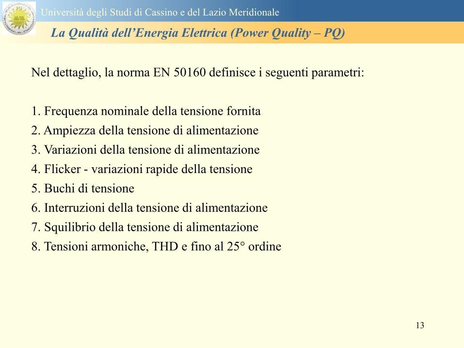
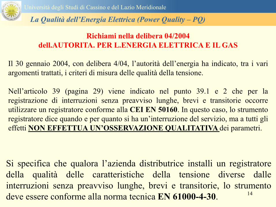
14
Si specifica che qualora lrsquoazienda distributrice installi un registratore
della qualitagrave delle caratteristiche della tensione diverse dalle
interruzioni senza preavviso lunghe brevi e transitorie lo strumento
deve essere conforme alla norma tecnica EN 61000-4-30
Richiami nella delibera 042004
dellAUTORITA PER LENERGIA ELETTRICA E IL GAS
Il 30 gennaio 2004 con delibera 404 lrsquoautoritagrave dellrsquoenergia ha indicato tra i vari
argomenti trattati i criteri di misura delle qualitagrave della tensione
Nellrsquoarticolo 39 (pagina 29) viene indicato nel punto 391 e 2 che per la
registrazione di interruzioni senza preavviso lunghe brevi e transitorie occorre
utilizzare un registratore conforme alla CEI EN 50160 In questo caso lo strumento
registratore dice quando e per quanto si ha unrsquointerruzione del servizio ma a tutti gli
effetti NON EFFETTUA UNrsquoOSSERVAZIONE QUALITATIVA dei parametri
Universitagrave degli Studi di Cassino e del Lazio Meridionale
La Qualitagrave dellrsquoEnergia Elettrica (Power Quality ndash PQ)
15
Universitagrave degli Studi di Cassino e del Lazio Meridionale
La Qualitagrave dellrsquoEnergia Elettrica (Power Quality ndash PQ)
16
17
Universitagrave degli Studi di Cassino e del Lazio Meridionale
La Qualitagrave dellrsquoEnergia Elettrica (Power Quality ndash PQ)
CURVA DI TOLLERANZA AI DISTURBI
18
Caratteristiche dellrsquoalimentazione a bassa tensione
Universitagrave degli Studi di Cassino e del Lazio Meridionale
La Qualitagrave dellrsquoEnergia Elettrica (Power Quality ndash PQ)
19
Caratteristiche dellrsquoalimentazione a bassa tensione
Frequenza nominale
La frequenza nominale della tensione fornita deve essere di 50 Hz In condizioni normali
di esercizio il valore medio misurato nellrsquointervallo di 10 secondi deve essere
Per i sistemi con collegamento sincrono ad un sistema interconnesso
1 50 Hz plusmn 1 durante il 95 di un anno
2 50 Hz +4 - 6 durante il 100 di un anno
Per i sistemi senza collegamento sincrono ad un sistema interconnesso
1 50 Hz plusmn 2 durante il 95 di un anno
2 50 Hz plusmn 15 durante il 100 di un anno
Universitagrave degli Studi di Cassino e del Lazio Meridionale
La Qualitagrave dellrsquoEnergia Elettrica (Power Quality ndash PQ)
20
Caratteristiche dellrsquoalimentazione a bassa tensione
Universitagrave degli Studi di Cassino e del Lazio Meridionale
La Qualitagrave dellrsquoEnergia Elettrica (Power Quality ndash PQ)
21
Caratteristiche dellrsquoalimentazione a bassa tensione
Universitagrave degli Studi di Cassino e del Lazio Meridionale
La Qualitagrave dellrsquoEnergia Elettrica (Power Quality ndash PQ)
22
Variazioni della tensione di alimentazione (variazioni lente)
Le variazioni lente sono deviazioni ldquomedierdquo dal valore nominale dellrsquoampiezza della
tensione di consegna entro una fascia predefinita (per esempio del plusmn10) rispetto alla
tensione dichiarata
CAUSE variazione lenta dei carichi e dalla corrispondente azione di regolazione effettuata dai
variatori sotto carico dei trasformatori
Universitagrave degli Studi di Cassino e del Lazio Meridionale
La Qualitagrave dellrsquoEnergia Elettrica (Power Quality ndash PQ)
23
Variazioni della tensione di alimentazione (variazioni rapide)
Le variazioni rapide sono abbassamenti (o aumenti) bruschi di qualche percento della
tensione preesistente generalmente seguiti se abbassamenti da un ritorno (a rampa o di
altra forma) ad un valore intermedio tra quello preesistente e tra il minimo raggiunto
CAUSE commutazione dei carichi (partenza motori in particolare) funzionamento di carichi
con ciclo operativo particolarmente variabile e in qualche caso da manovre in rete (linee
trasformatori condensatori ecc)
Universitagrave degli Studi di Cassino e del Lazio Meridionale
La Qualitagrave dellrsquoEnergia Elettrica (Power Quality ndash PQ)
24
Flicker Il flicker egrave originato dalla fluttuazione della tensione Si definisce fluttuazione di tensione una
serie di variazioni rapide (uguali o diverse) della tensione
Fluttuazioni di tensione che presentano frequenze di modulazione del 50 Hz comprese tra 05 e
40 Hz danno origine al fenomeno del flicker (sfarfallio) ovvero della sensazione visiva
provocata dalle fluttuazioni dellrsquointensitagrave di illuminazione delle lampade
I suoi principali effetti sullrsquouomo possono essere mal di testa irritabilitagrave e fastidio agli occhi
Universitagrave degli Studi di Cassino e del Lazio Meridionale
La Qualitagrave dellrsquoEnergia Elettrica (Power Quality ndash PQ)
25
Universitagrave degli Studi di Cassino e del Lazio Meridionale
La Qualitagrave dellrsquoEnergia Elettrica (Power Quality ndash PQ)
26
La Qualitagrave dellrsquoEnergia Elettrica (Power Quality ndash PQ)
Universitagrave degli Studi di Cassino e del Lazio Meridionale
La Qualitagrave dellrsquoEnergia Elettrica (Power Quality ndash PQ)
27
Universitagrave degli Studi di Cassino e del Lazio Meridionale
La Qualitagrave dellrsquoEnergia Elettrica (Power Quality ndash PQ)
28
Universitagrave degli Studi di Cassino e del Lazio Meridionale
La Qualitagrave dellrsquoEnergia Elettrica (Power Quality ndash PQ)
29
Universitagrave degli Studi di Cassino e del Lazio Meridionale
La Qualitagrave dellrsquoEnergia Elettrica (Power Quality ndash PQ)
30
Universitagrave degli Studi di Cassino e del Lazio Meridionale
La Qualitagrave dellrsquoEnergia Elettrica (Power Quality ndash PQ)
31
Universitagrave degli Studi di Cassino e del Lazio Meridionale
La Qualitagrave dellrsquoEnergia Elettrica (Power Quality ndash PQ)
32
Buchi di tensione Riduzione temporanea della tensione in un punto della rete elettrica sotto una determinata
soglia Se durante un buco la tensione scende sotto una soglia di interruzione lrsquoevento egrave
considerato essere sia un buco che unrsquointerruzione
CAUSE I buchi di tensione sono generalmente dovuti a guasti che sopravvengono negli
impianti utilizzatori o nel sistema di distribuzione pubblico Possono dipendere anche variazioni
di carico lungo la linea
Universitagrave degli Studi di Cassino e del Lazio Meridionale
La Qualitagrave dellrsquoEnergia Elettrica (Power Quality ndash PQ)
33
Interruzioni della tensione di alimentazione Condizione in cui la tensione ad un terminale della rete egrave inferiore allrsquo1 della tensione
nominale per una durata fino a tre minuti (brevi) o maggiori di 3 minuti (lunghe)
Universitagrave degli Studi di Cassino e del Lazio Meridionale
La Qualitagrave dellrsquoEnergia Elettrica (Power Quality ndash PQ)
34
Sovratensioni temporanee alla frequenza di rete fra fasi e terra Le sovratensioni sono sopraelevazioni della tensione conseguenti a modificazioni dello
stato elettrico della rete elettrica
Universitagrave degli Studi di Cassino e del Lazio Meridionale
La Qualitagrave dellrsquoEnergia Elettrica (Power Quality ndash PQ)
35
Armoniche Le armoniche sono tensioni o correnti sinusoidali con frequenza pari ad un multiplo intero
(ordine) della frequenza fondamentale di funzionamento del sistema elettrico la cui
presenza determina una distorsione della forma drsquoonda della tensione di alimentazione
CAUSE In piccola parte dal sistema stesso (trasformatori etc) e per la maggior parte da
apparecchi utilizzatori carichi commutati elettronicamente raddrizzatori convertitori regolatori
in AC cicloconvertitori ecc carichi con caratteristiche non lineari apparecchiature a
saturazione magnetica lampade a scarica forni ad arco saldatrici ad arco trasformatori ecc
bull carichi inseriti e disinseriti da organi di manovra condensatori filtri e motori a induzione
Universitagrave degli Studi di Cassino e del Lazio Meridionale
La Qualitagrave dellrsquoEnergia Elettrica (Power Quality ndash PQ)
36
Armoniche di tensione e corrente ndash Problemi
Vi sono diversi ambiti causati dalle armoniche
bull problemi causati da armoniche di corrente
1048707 sovraccarico del neutro
1048707 aumento delle perdite nei trasformatori
1048707 interventi intempestivi degli interruttori automatici
1048707 aumento dellrsquoeffetto pelle
bull problemi causati da armoniche di tensione
1048707 deformazione della tensione
1048707 disturbi nella coppia dei motori ad induzione
1048707 rumore al passaggio per lo zero
bull problemi causati quando le armoniche di corrente raggiungono lrsquoalimentazione
Universitagrave degli Studi di Cassino e del Lazio Meridionale
La Qualitagrave dellrsquoEnergia Elettrica (Power Quality ndash PQ)
37
38
Universitagrave degli Studi di Cassino e del Lazio Meridionale
La Qualitagrave dellrsquoEnergia Elettrica (Power Quality ndash PQ)
39
Strumentazione ldquohand heldrdquo con display
Universitagrave degli Studi di Cassino e del Lazio Meridionale
La Qualitagrave dellrsquoEnergia Elettrica (Power Quality ndash PQ)
40
Strumentazione ldquohand heldrdquo con display
Universitagrave degli Studi di Cassino e del Lazio Meridionale
La Qualitagrave dellrsquoEnergia Elettrica (Power Quality ndash PQ)
41
Strumentazione da registrazione
Universitagrave degli Studi di Cassino e del Lazio Meridionale
La Qualitagrave dellrsquoEnergia Elettrica (Power Quality ndash PQ)
42
Schema di principio ndash 61000-4-30 copy IEC2008
The electrical quantity to be measured may be either directly accessible as is
generally the case in low-voltage systems or accessible via measurement
transducers
An instrument may include the whole measurement chain In this standard the
normative part does not consider the measurement transducers external to the
instrument and their associated uncertainty
Universitagrave degli Studi di Cassino e del Lazio Meridionale
La Qualitagrave dellrsquoEnergia Elettrica (Power Quality ndash PQ)
43
Universitagrave degli Studi di Cassino Corso di Fondamenti di Misure
La Qualitagrave dellrsquoEnergia Elettrica (Power Quality ndash PQ)
Classi dei metodi di misura - 61000-4-30 copy IEC2008
For each class measurement methods and appropriate performance requirements
are included
Sono definite tre classi A S e B
Class A
This class is used where precise measurements are necessary for example for contractual
applications that may require resolving disputes verifying compliance with standards etc
Any measurements of a parameter carried out with two different instruments complying with
the requirements of Class A when measuring the same signals will produce matching results
within the specified uncertainty for that parameter
Class S
This class is used for statistical applications such as surveys or power quality assessment
possibly with a limited subset of parameters Although it uses equivalent intervals of
measurement as class A the class S processing requirements are lower
Class B
This class is defined in order to avoid making many existing instruments designs obsolete
NOTE Class B methods are not recommended for new designs Readers are advised that Class B may be removed in a
future Edition of this standard
44
Classi dei metodi di misura - 61000-4-30 copy IEC2008
Measurement aggregation over time intervals
CLASS A
The basic measurement time interval for parameter magnitudes (supply voltage harmonics
interharmonics and unbalance) shall be a 10-cycle time interval for a 50 Hz power system
or 12-cycle time interval for a 60 Hz power system
The 1012-cycle measurement shall be re-synchronized at every RTC 10 min tick
The 1012-cycle values are then aggregated over 3 additional intervals
ndash 150180-cycle interval (150 cycles for 50 Hz nominal or 180 cycles for 60 Hz nominal)
ndash 10 min interval
ndash 2 h interval
CLASS S
Same time intervals as Class A
CLASS B
The manufacturer shall specify the number and duration of aggregation time intervals
Universitagrave degli Studi di Cassino e del Lazio Meridionale
La Qualitagrave dellrsquoEnergia Elettrica (Power Quality ndash PQ)
45
Universitagrave degli Studi di Cassino e del Lazio Meridionale
La Qualitagrave dellrsquoEnergia Elettrica (Power Quality ndash PQ)
46
Universitagrave degli Studi di Cassino e del Lazio Meridionale
La Qualitagrave dellrsquoEnergia Elettrica (Power Quality ndash PQ)
Class A
The 10-min aggregated value shall be tagged with the absolute time (for
example 01H1000) The time tag is the time at the conclusion of the 10-min
aggregation
The data for the 10-min time interval shall be aggregated from 1012-cycle time
intervals
Each 10-minute interval shall begin on a UTC 10-min tick The 10-min tick is
also used to re-synchronize the 1012-cycle intervals and the 150180-cycle
intervals
The final 1012-cycle interval(s) in a 10-min aggregation period will typically
overlap in time with the UTC 10-min clock tick Any overlapping 1012-cycle
interval (Overlap 1 in Figure 2) is included in the aggregation of the previous
10-min interval
47
Universitagrave degli Studi di Cassino e del Lazio Meridionale
La Qualitagrave dellrsquoEnergia Elettrica (Power Quality ndash PQ)
48
Universitagrave degli Studi di Cassino e del Lazio Meridionale
La Qualitagrave dellrsquoEnergia Elettrica (Power Quality ndash PQ)
49
Classi dei metodi di misura - 61000-4-30 copy IEC2008
Real time clock (RTC) uncertainty
Sono definite le specifiche per le 3 classi
Flagging concept
During a dip swell or interruption the measurement algorithm for other
parameters (for example frequency measurement) might produce an unreliable
value The flagging concept therefore avoids counting a single event more than
once in different parameters (for example counting a single dip as both a dip and a
frequency variation) and indicates that an aggregated value might be unreliable
Universitagrave degli Studi di Cassino e del Lazio Meridionale
La Qualitagrave dellrsquoEnergia Elettrica (Power Quality ndash PQ)
50
Classi dei metodi di misura - 61000-4-30 copy IEC2008
Power quality parameters - INDICES
Per ogni parametro viene suggerito il metodo di misura per le tre classi e
(soprattutto) le caratteristiche di precisione Per alcuni parametri rimanda a
specifiche norme (ad esempio Flicker e Armonicheinterarmoniche)
Esempio - Power frequency Class A
The frequency reading shall be obtained every 10 s As power frequency may not be exactly 50 Hz or 60
Hz within the 10 s time clock interval the number of cycles may not be an integer number The
fundamental frequency output is the ratio of the number of integral cycles counted during the 10 s time
clock interval divided by the cumulative duration of the integer cycles Before each assessment
harmonics and interharmonics shall be attenuated to minimize the effects of multiple zero crossings
The measurement time intervals shall be non-overlapping Individual cycles that overlap the 10 s time
clock are discarded Each 10 s interval shall begin on an absolute 10 s time clock with uncertainty as
defined in 46
Other techniques that provide equivalent results such as convolution are acceptable
Class S Same as class A
Class B The manufacturer shall specify the process used for frequency measurement
Universitagrave degli Studi di Cassino e del Lazio Meridionale
La Qualitagrave dellrsquoEnergia Elettrica (Power Quality ndash PQ)
51
Classi dei metodi di misura - 61000-4-30 copy IEC2008
Power quality parameters - INDICES
Per ogni parametro viene suggerito il metodo di misura per le tre classi e
(soprattutto) le caratteristiche di precisione Per alcuni parametri rimanda a
specifiche norme (ad esempio Flicker e Armonicheinterarmoniche)
Esempio - Power frequency
Measurement uncertainty and measuring range
ndash Class A
Under the conditions described in 61 the measurement uncertainty shall not exceed
plusmn10 mHz over the measuring ranges 425 Hz ~ 575 Hz 51 Hz ~ 69 Hz
ndash Class S
Under the conditions described in 61 the measurement uncertainty shall not exceed
plusmn50 mHz over the measuring ranges 425 Hz ~ 575 Hz 51 Hz ~ 69 Hz
ndash Class B
The manufacturer shall specify the uncertainty over the measuring ranges 425 Hz ~
575 Hz 51 Hz ~ 69 Hz
Universitagrave degli Studi di Cassino e del Lazio Meridionale
La Qualitagrave dellrsquoEnergia Elettrica (Power Quality ndash PQ)
52
Magnitude of the supply voltage
Measurement method
ndash Class A
The measurement shall be the rms value of the voltage magnitude over
a 10-cycle time interval for 50 Hz power system or 12-cycle time
interval for 60 Hz power system Every 1012-cycle interval shall be
contiguous and not overlapping with adjacent 1012-cycle intervals
except as shown as Overlap 1 in Figure 2
NOTE 1 This specific measurement method is used for quasi-stationary signals and is
not used for the detection and measurement of disturbances dips swells voltage
interruptions and transients
NOTE 2 The rms value includes by definition harmonics interharmonics mains
signalling etc
- Class S same as Class A
Universitagrave degli Studi di Cassino e del Lazio Meridionale
La Qualitagrave dellrsquoEnergia Elettrica (Power Quality ndash PQ)
53
Magnitude of the supply voltage
Measurement uncertainty and measuring range
ndash Class A
Under the conditions described in Clause 6 the measurement uncertainty
shall not exceed plusmn01 of Udin over the range of 10 ~ 150 of Udin
ndash Class S
Under the conditions described in Clause 6 the measurement uncertainty
shall not exceed plusmn05 of Udin over the range of 20 ~ 120 of Udin
Universitagrave degli Studi di Cassino e del Lazio Meridionale
La Qualitagrave dellrsquoEnergia Elettrica (Power Quality ndash PQ)
54
Supply voltage dips and swells
Measurement method
ndash Class A
The basic measurement Urms of a voltage dip and swell shall be the
Urms(frac12) on each measurement channel (see Clause 322)
The cycle duration for Urms(frac12) depends on the frequency The
frequency might be determined by the last non-flagged power frequency
measurement (see Clause 47 and Clause 51) or by any other method
that yields the uncertainty requirements of Clause 6
NOTE 1 The Urms(frac12) value includes by definition harmonics interharmonics mains
signalling voltage etc
NOTE 2 It is important to avoid loss of data when dips and swells occur in a rapid
sequence (for example three events in one second with up to one minute between
sequences may occur when a recloser operates into a sustained fault) If during a rapid
burst the dipswell event characteristics cannot be recorded then a count of events may
be useful
Universitagrave degli Studi di Cassino e del Lazio Meridionale
La Qualitagrave dellrsquoEnergia Elettrica (Power Quality ndash PQ)
55
Supply voltage dips and swells
Detection and evaluation of a voltage dip
Voltage dip detection
The dip threshold is a percentage of either Udin or the sliding voltage
reference Usr (see 525 544) The user shall declare the reference
voltage in use
NOTE ndash On single-phase systems a voltage dip begins when the Urms voltage falls
below the dip threshold and ends when the Urms voltage is equal to or above the dip
threshold plus the hysteresis voltage
ndash On polyphase systems a dip begins when the Urms voltage of one or more channels is
below the dip threshold and ends when the Urms voltage on all measured channels is
equal to or above the dip threshold plus the hysteresis voltage
The dip threshold and the hysteresis voltage are both set by the user according to the
use
Universitagrave degli Studi di Cassino e del Lazio Meridionale
La Qualitagrave dellrsquoEnergia Elettrica (Power Quality ndash PQ)
56
Calculation of a sliding reference voltage
The sliding reference voltage implementation is optional not mandatory
If a sliding reference is chosen for voltage dip or swell detection this
shall be calculated using a first-order filter with a 1-min time constant
This filter is given by
Usr(n) = 09967 times Usr(nndash1) + 00033 times U(1012)rms
where
Usr(n) is the present value of the sliding reference voltage
Usr(nndash1) is the previous value of the sliding reference voltage and
U(1012)rms is the most recent 1012-cycle rms value
When the measurement is started the initial value of the sliding reference voltage is set
to the declared input voltage The sliding reference voltage is updated every 1012-
cycles If a 1012-cycle value is flagged the sliding reference voltage is not updated
and the previous value is used
Universitagrave degli Studi di Cassino e del Lazio Meridionale
La Qualitagrave dellrsquoEnergia Elettrica (Power Quality ndash PQ)
57
Supply voltage dips and swells
Voltage dip evaluation
A voltage dip is characterized by a pair of data either residual voltage
(Ures) or depth and duration
ndash the residual voltage of a voltage dip is the lowest Urms(frac12) value
measured on any channel during the dip
ndash the depth is the difference between the reference voltage (either Udin
or Usr) and the residual voltage It is generally expressed in percentage
of the reference voltage
NOTE 1 During the dip it may be useful to also record the lowest Urms(frac12) on each
channel in addition to the residual voltage of the dip The duration spent below the dip
threshold on each channel may also be useful
Universitagrave degli Studi di Cassino e del Lazio Meridionale
La Qualitagrave dellrsquoEnergia Elettrica (Power Quality ndash PQ)
58
Supply voltage dips and swells
Voltage dip evaluation
NOTE 2 If voltage waveforms are recorded before during and after a
dip useful information about phase angle changes may be available in
the recorded data
The start time of a dip shall be time stamped with the time of the start of
the Urms of the channel that initiated the event and the end time of the
dip shall be the time stamped with the time of the end of the Urms that
ended the event as defined by the threshold plus the hysteresis
The duration of a voltage dip is the time difference between the start
time and the end time of the voltage dip
Universitagrave degli Studi di Cassino e del Lazio Meridionale
La Qualitagrave dellrsquoEnergia Elettrica (Power Quality ndash PQ)
59
Supply voltage dips and swells
Residual voltage and swell voltage magnitude measurement
uncertainty
ndash Class A
The measurement uncertainty shall not exceed plusmn02 of Udin
ndash Class S
The measurement uncertainty shall not exceed plusmn10 of Udin
Universitagrave degli Studi di Cassino e del Lazio Meridionale
La Qualitagrave dellrsquoEnergia Elettrica (Power Quality ndash PQ)
60
Schema di principio ndash 61000-4-7 copy IEC2002
Universitagrave degli Studi di Cassino e del Lazio Meridionale
La Qualitagrave dellrsquoEnergia Elettrica (Power Quality ndash PQ)
61
Universitagrave degli Studi di Cassino e del Lazio Meridionale
La Qualitagrave dellrsquoEnergia Elettrica (Power Quality ndash PQ)
62
Universitagrave degli Studi di Cassino e del Lazio Meridionale
La Qualitagrave dellrsquoEnergia Elettrica (Power Quality ndash PQ)
63
Inter-Armoniche Le inter-armoniche sono tensioni o correnti sinusoidali con frequenza diversa da un
multiplo intero della fondamentale la cui presenza determina una distorsione
(modulazione) della forma donda della tensione di alimentazione
CAUSE dai carichi che assorbono correnti inter-armoniche
- carichi commutati elettronicamente convertitori cascata subsincrona cicloconvertitori regolatori con
controllo a pacchetti di cicli ecc
- carichi con caratteristiche non lineari eo non stazionarie forni ad arco saldatrici ad arco ecc
Universitagrave degli Studi di Cassino e del Lazio Meridionale
La Qualitagrave dellrsquoEnergia Elettrica (Power Quality ndash PQ)
64
Universitagrave degli Studi di Cassino e del Lazio Meridionale
La Qualitagrave dellrsquoEnergia Elettrica (Power Quality ndash PQ)
Un porsquo di esempi e
consigli praticihellip
65
0V
50V
100V
150V
200V
250V
300V
350V
0ms 5ms 10ms 15ms 20ms
t
u
0A
1A
2A
3A
i
0V
50V
100V
150V
200V
250V
300V
350V
0ms 5ms 10ms 15ms 20ms
t
u
0A
1A
2A
3A
i
0V
50V
100V
150V
200V
250V
300V
350V
0ms 5ms 10ms 15ms 20ms
t
u
0A
1A
2A
3A
i
gleichgerichtete
Netzspannung
Kondensator-
spannung
gleichgerichteter
Netzstrom
The situation
today
bull Computed current and voltage profiles when a
230 V 58 W fluorescent lamp with an old-style
electronic ballast is driven on the phase wire of
a typical power distribution system
System voltage 230 V
System frequency 50 Hz
Source resistance 500 mW
Longitudinal induction 904 microH
System impedance 575 mW
Mean dc current 180 mA
Smoothing capacitance220 microF
66
And what about electronic ballasts that are rated over 25W
Introduce electronic power factor correction (PFC)
0V
20V
40V
60V
80V
100V
120V
140V
160V
180V
200V
220V
0deg 15deg 30deg 45deg
u
00A
03A
06A
09A
12A
i
67
Though todayrsquos ballasts are better if
rated gt25 W bull Only
the
small
ones
continu
e to
pollute
just like
PCs
TV sets
do
68
This leads to a number of
previously unknown effects bull 1 Deformed voltage curves
bull 2 Huge inrush current peaks
bull 3 Instrument dependent measured parameters
bull 4 Increased loading of phase conductors
bull 5 Loading and overloading of the neutral conductor
bull 6 Overheating and start-up problems of induction motors
bull 7 Additional stray losses in transformers
bull 8 Repercussions of generators upon the mains
bull 9 Influence of capacitors repercussions upon the mains
and four additional complications in TN-C systems
10 Stray currents in equipotential bonding system magnetic fields
11 Contamination of data streams by stray currents
12 Stray currents in the earthing system corrosion damage
13 Lightning currents in devices and equipment
69
1 Deformed voltage curves
bull in theory
-350V
-300V
-250V
-200V
-150V
-100V
-50V
0V
50V
100V
150V
200V
250V
300V
350V
0 5 10 15 20
t ms
u
System voltage profile when driving
a single-phase load comprising
twenty 58 W energy-saver lamps in
parallel on a typical 230 V power
system
70
and in practice
bull An actual
current profile
bull
bull and
bull a voltage profile
bull
bull recorded in a large storage
dispatch and administrative
building
71
at home or in industrial environments
bull
bull Television 40
W
bull 200 Vdiv 2
Adiv
bull 5 msdiv
Harmonic
spectrum
Frequency
converter
50 Adiv
Phase currents
I1=I2=I3=160 A
IN=295 A
5 msdiv
72
Every periodic waveform can be written
as the infinite sum of sinusoidal waves
-175
-150
-125
-100
-75
-50
-25
0
25
50
75
100
125
150
175
0 5 10 15 20
t ms
i
mA
itot
i1
Synthesis of a triangular current profile 100mA
Content fundamental I = 99 mA Isup2 = 9855 mAsup2
Sum of squares Isup2 = 9855 mAsup2
Root of sum = RMS value I = 99 mA
-175
-150
-125
-100
-75
-50
-25
0
25
50
75
100
125
150
175
0 5 10 15 20
t ms
i
mA
itot
i1
i3
Synthesis of a triangular current profile 100mA
Content fundamental I = 99 mA Isup2 = 9855 mAsup2
Cont 3 rd harmonic I = -11 mA Isup2 = 122 mAsup2
Sum of squares Isup2 = 9977 mAsup2
Root of sum = RMS value I = 100 mA
-175
-150
-125
-100
-75
-50
-25
0
25
50
75
100
125
150
175
0 5 10 15 20
t ms
i
mA
itot
i1
i3
i5
Synthesis of a triangular current profile 100mA
Content fundamental I = 99 mA Isup2 = 9855 mAsup2
Cont 3 rd harmonic I = -11 mA Isup2 = 122 mAsup2
Cont 5 th harmonic I = 4 mA Isup2 = 16 mAsup2
Sum of squares Isup2 = 9993 mAsup2
Root of sum = RMS value I = 100 mA
-175
-150
-125
-100
-75
-50
-25
0
25
50
75
100
125
150
175
0 5 10 15 20
t ms
i
mA
itot
i1
i3
i5
i7
Synthesis of a triangular current profile 100mA
Content fundamental I = 99 mA Isup2 = 9855 mAsup2
Cont 3 rd harmonic I = -11 mA Isup2 = 122 mAsup2
Cont 5 th harmonic I = 4 mA Isup2 = 16 mAsup2
Cont 7 th harmonic I = -2 mA Isup2 = 4 mAsup2
Sum of squares Isup2 = 9997 mAsup2
Root of sum = RMS value I = 100 mA
-175
-150
-125
-100
-75
-50
-25
0
25
50
75
100
125
150
175
0 5 10 15 20
t ms
i
mA
itot i1
i3 i5
i7 i9
Synthesis of a triangular current profile 100mA
Content fundamental I = 99 mA Isup2 = 9855 mAsup2
Cont 3 rd harmonic I = -11 mA Isup2 = 122 mAsup2
Cont 5 th harmonic I = 4 mA Isup2 = 16 mAsup2
Cont 7 th harmonic I = -2 mA Isup2 = 4 mAsup2
Cont 9 th harmonic I = 1 mA Isup2 = 2 mAsup2
Sum of squares Isup2 = 9998 mAsup2
Root of sum = RMS value I = 100 mA
-175
-150
-125
-100
-75
-50
-25
0
25
50
75
100
125
150
175
0 5 10 15 20
t ms
i
mA
itot i1
i3 i5
i7 i9
i11
Synthesis of a triangular current profile 100mA
Content fundamental I = 99 mA Isup2 = 9855 mAsup2
Cont 3 rd harmonic I = -11 mA Isup2 = 122 mAsup2
Cont 5 th harmonic I = 4 mA Isup2 = 16 mAsup2
Cont 7 th harmonic I = -2 mA Isup2 = 4 mAsup2
Cont 9 th harmonic I = 1 mA Isup2 = 2 mAsup2
Cont 11 th harmonic I = -1 mA Isup2 = 1 mAsup2
Sum of squares Isup2 = 9999 mAsup2
Root of sum = RMS value I = 100 mA
-175
-150
-125
-100
-75
-50
-25
0
25
50
75
100
125
150
175
0 5 10 15 20
t ms
i
mA
itot i1
i3 i5
i7 i9
i11 i13
Synthesis of a triangular current profile 100mA
Content fundamental I = 99 mA Isup2 = 9855 mAsup2
Cont 3 rd harmonic I = -11 mA Isup2 = 122 mAsup2
Cont 5 th harmonic I = 4 mA Isup2 = 16 mAsup2
Cont 7 th harmonic I = -2 mA Isup2 = 4 mAsup2
Cont 9 th harmonic I = 1 mA Isup2 = 2 mAsup2
Cont 11 th harmonic I = -1 mA Isup2 = 1 mAsup2
Cont 13 th harmonic I = 1 mA Isup2 = 0 mAsup2
Sum of squares Isup2 = 9999 mAsup2
Root of sum = RMS value I = 100 mA
-175
-150
-125
-100
-75
-50
-25
0
25
50
75
100
125
150
175
0 5 10 15 20
t ms
i
mA
itot i1
i3 i5
i7 i9
i11 i13
i15
Synthesis of a triangular current profile 100mA
Content fundamental I = 99 mA Isup2 = 9855 mAsup2
Cont 3 rd harmonic I = -11 mA Isup2 = 122 mAsup2
Cont 5 th harmonic I = 4 mA Isup2 = 16 mAsup2
Cont 7 th harmonic I = -2 mA Isup2 = 4 mAsup2
Cont 9 th harmonic I = 1 mA Isup2 = 2 mAsup2
Cont 11 th harmonic I = -1 mA Isup2 = 1 mAsup2
Cont 13 th harmonic I = 1 mA Isup2 = 0 mAsup2
Cont 15 th harmonic I = 0 mA Isup2 = 0 mAsup2
Sum of squares Isup2 = 10000 mAsup2
Root of sum = RMS value I = 100 mA
-175
-150
-125
-100
-75
-50
-25
0
25
50
75
100
125
150
175
0 5 10 15 20
t ms
i
mA
itot i1
i3 i5
i7 i9
i11 i13
i15 i17
Synthesis of a triangular current profile 100mA
Content fundamental I = 99 mA Isup2 = 9855 mAsup2
Cont 3 rd harmonic I = -11 mA Isup2 = 122 mAsup2
Cont 5 th harmonic I = 4 mA Isup2 = 16 mAsup2
Cont 7 th harmonic I = -2 mA Isup2 = 4 mAsup2
Cont 9 th harmonic I = 1 mA Isup2 = 2 mAsup2
Cont 11 th harmonic I = -1 mA Isup2 = 1 mAsup2
Cont 13 th harmonic I = 1 mA Isup2 = 0 mAsup2
Cont 15 th harmonic I = 0 mA Isup2 = 0 mAsup2
Cont 17 th harmonic I = 0 mA Isup2 = 0 mAsup2
Sum of squares Isup2 = 10000 mAsup2
Root of sum = RMS value I = 100 mA
73
whose frequencies called harmonics are
integer multiples of the fundamental frequency
-175
-150
-125
-100
-75
-50
-25
0
25
50
75
100
125
150
175
0 5 10 15 20
t ms
i
mA
itot
i1
Synthesis of a rectangular current profile 100mA
Content fundamental I = 90 mA Isup2 = 8106 mAsup2
Sum of squares Isup2 = 8106 mAsup2
Root of sum = RMS value I = 90 mA
-175
-150
-125
-100
-75
-50
-25
0
25
50
75
100
125
150
175
0 5 10 15 20
t ms
i
mA
itot
i1
i3
Synthesis of a rectangular current profile 100mA
Content fundamental I = 90 mA Isup2 = 8106 mAsup2
Cont 3 rd harmonic I = 30 mA Isup2 = 901 mAsup2
Sum of squares Isup2 = 9006 mAsup2
Root of sum = RMS value I = 95 mA
-175
-150
-125
-100
-75
-50
-25
0
25
50
75
100
125
150
175
0 5 10 15 20
t ms
i
mA
itot
i1
i3
i5
Synthesis of a rectangular current profile 100mA
Content fundamental I = 90 mA Isup2 = 8106 mAsup2
Cont 3 rd harmonic I = 30 mA Isup2 = 901 mAsup2
Cont 5 th harmonic I = 18 mA Isup2 = 324 mAsup2
Sum of squares Isup2 = 9331 mAsup2
Root of sum = RMS value I = 97 mA
-175
-150
-125
-100
-75
-50
-25
0
25
50
75
100
125
150
175
0 5 10 15 20
t ms
i
mA
itot
i1
i3
i5
i7
Synthesis of a rectangular current profile 100mA
Content fundamental I = 90 mA Isup2 = 8106 mAsup2
Cont 3 rd harmonic I = 30 mA Isup2 = 901 mAsup2
Cont 5 th harmonic I = 18 mA Isup2 = 324 mAsup2
Cont 7 th harmonic I = 13 mA Isup2 = 165 mAsup2
Sum of squares Isup2 = 9496 mAsup2
Root of sum = RMS value I = 97 mA
-175
-150
-125
-100
-75
-50
-25
0
25
50
75
100
125
150
175
0 5 10 15 20
t ms
i
mA
itot i1
i3 i5
i7 i9
Synthesis of a rectangular current profile 100mA
Content fundamental I = 90 mA Isup2 = 8106 mAsup2
Cont 3 rd harmonic I = 30 mA Isup2 = 901 mAsup2
Cont 5 th harmonic I = 18 mA Isup2 = 324 mAsup2
Cont 7 th harmonic I = 13 mA Isup2 = 165 mAsup2
Cont 9 th harmonic I = 10 mA Isup2 = 100 mAsup2
Sum of squares Isup2 = 9596 mAsup2
Root of sum = RMS value I = 98 mA
-175
-150
-125
-100
-75
-50
-25
0
25
50
75
100
125
150
175
0 5 10 15 20
t ms
i
mA
itot i1
i3 i5
i7 i9
i11
Synthesis of a rectangular current profile 100mA
Content fundamental I = 90 mA Isup2 = 8106 mAsup2
Cont 3 rd harmonic I = 30 mA Isup2 = 901 mAsup2
Cont 5 th harmonic I = 18 mA Isup2 = 324 mAsup2
Cont 7 th harmonic I = 13 mA Isup2 = 165 mAsup2
Cont 9 th harmonic I = 10 mA Isup2 = 100 mAsup2
Cont 11 th harmonic I = 8 mA Isup2 = 67 mAsup2
Sum of squares Isup2 = 9663 mAsup2
Root of sum = RMS value I = 98 mA
-175
-150
-125
-100
-75
-50
-25
0
25
50
75
100
125
150
175
0 5 10 15 20
t ms
i
mA
itot i1
i3 i5
i7 i9
i11 i13
Synthesis of a rectangular current profile 100mA
Content fundamental I = 90 mA Isup2 = 8106 mAsup2
Cont 3 rd harmonic I = 30 mA Isup2 = 901 mAsup2
Cont 5 th harmonic I = 18 mA Isup2 = 324 mAsup2
Cont 7 th harmonic I = 13 mA Isup2 = 165 mAsup2
Cont 9 th harmonic I = 10 mA Isup2 = 100 mAsup2
Cont 11 th harmonic I = 8 mA Isup2 = 67 mAsup2
Cont 13 th harmonic I = 7 mA Isup2 = 48 mAsup2
Sum of squares Isup2 = 9711 mAsup2
Root of sum = RMS value I = 99 mA
-175
-150
-125
-100
-75
-50
-25
0
25
50
75
100
125
150
175
0 5 10 15 20
t ms
i
mA
itot i1
i3 i5
i7 i9
i11 i13
i15
Synthesis of a rectangular current profile 100mA
Content fundamental I = 90 mA Isup2 = 8106 mAsup2
Cont 3 rd harmonic I = 30 mA Isup2 = 901 mAsup2
Cont 5 th harmonic I = 18 mA Isup2 = 324 mAsup2
Cont 7 th harmonic I = 13 mA Isup2 = 165 mAsup2
Cont 9 th harmonic I = 10 mA Isup2 = 100 mAsup2
Cont 11 th harmonic I = 8 mA Isup2 = 67 mAsup2
Cont 13 th harmonic I = 7 mA Isup2 = 48 mAsup2
Cont 15 th harmonic I = 6 mA Isup2 = 36 mAsup2
Sum of squares Isup2 = 9747 mAsup2
Root of sum = RMS value I = 99 mA
-175
-150
-125
-100
-75
-50
-25
0
25
50
75
100
125
150
175
0 5 10 15 20
t ms
i
mA
itot i1
i3 i5
i7 i9
i11 i13
i15 i17
Synthesis of a rectangular current profile 100mA
Content fundamental I = 90 mA Isup2 = 8106 mAsup2
Cont 3 rd harmonic I = 30 mA Isup2 = 901 mAsup2
Cont 5 th harmonic I = 18 mA Isup2 = 324 mAsup2
Cont 7 th harmonic I = 13 mA Isup2 = 165 mAsup2
Cont 9 th harmonic I = 10 mA Isup2 = 100 mAsup2
Cont 11 th harmonic I = 8 mA Isup2 = 67 mAsup2
Cont 13 th harmonic I = 7 mA Isup2 = 48 mAsup2
Cont 15 th harmonic I = 6 mA Isup2 = 36 mAsup2
Cont 17 th harmonic I = 5 mA Isup2 = 28 mAsup2
Sum of squares Isup2 = 9775 mAsup2
Root of sum = RMS value I = 99 mA
74
Even far better simulations are
available free of charge at
bull wwwpowerstandardscomMcEachern
75
-4A
-3A
-2A
-1A
0A
1A
2A
3A
4A
0ms 5ms 10ms 15ms 20ms
t
i
-4A
-3A
-2A
-1A
0A
1A
2A
3A
4A
0ms 5ms 10ms 15ms 20ms
t
i
Applying the Fourier
analysis to a real PC
current does not work
directly
bull
bull but it can be
modelled by a similar
triangular curve in
which not all of the
higher harmonics
have been included
Triangular current profile of
the same amplitude and a
pulse duty cycle of 17
Input current of a PC
with monitor
76
Analysis of the model triangular waveform
-400
-350
-300
-250
-200
-150
-100
-50
0
50
100
150
200
250
300
350
400
0 5 10 15 20
t ms
iI
itot(t) L1 [A] i1(t) L1 [A]
i3(t) L1 [A] i5(t) L1 [A]
i7(t) L1 [A] i9(t) L1 [A]
i11(t) L1 [A] i13(t) L1 [A]
i15(t) L1 [A] i17(t) L1 [A]
77
M3
Harmonics
Energy
(active
power)
L1
L2
L3
N
PE
Important
bull Harmonics are created within the loads
themselves and can flow ldquoupstreamrdquo to
contaminate the power system
78
-6A
-5A
-4A
-3A
-2A
-1A
0A
1A
2A
3A
4A
5A
6A
0ms 5ms 10ms 15ms 20ms
t
i
Squared values
Without
Fundamental 502 mA 251986 mAsup2 the fundamental
3rd harmonic -479 mA 229000 mAsup2 229000 mAsup2
5th harmonic 434 mA 188595 mAsup2 188595 mAsup2
7th harmonic -374 mA 139903 mAsup2 139903 mAsup2
9th harmonic 304 mA 92527 mAsup2 92527 mAsup2
11th harmonic -232 mA 53671 mAsup2 53671 mAsup2
13th harmonic 163 mA 26600 mAsup2 26600 mAsup2
15th harmonic -104 mA 10780 mAsup2 10780 mAsup2
17th harmonic 57 mA 3299 mAsup2 3299 mAsup2
Sum of the squares 996362 mAsup2 744377 mAsup2
Root thereof 998 mAeff THD = 863 mA
What actually is THD Example shown here triangular current
profile with an rms current of 1000 mA
and a pulse duty cycle of 17
THDr (root mean square) = 863mA1000mA = 86
THDf (fundamental) = 863mA502mA = 172
79
Effect on phase-to-neutral
and phase-to-phase voltages
bull Recorded
on June
30 2002
230 p
m
bull What
was the
matter
then
bull The
soccer
final
Germany
vs
Brazil
80
The triple-N harmonics drive
a circulating current in the
delta winding of a distribution
transformer
bull but the
bull voltage harmonics
propagate into the next
low-voltage power
distribution system
81 0V
50V
100V
150V
200V
250V
300V
350V
400V
450V
500V
550V
0 10 20 30 40 50
t ms
u
0A
10A
20A
30A
40A
50A
60A
70A
80A
90A
100A
110A
120A
130A
140A
150A
i
Switching on just as supply voltage passes through zero
0V
50V
100V
150V
200V
250V
300V
350V
400V
450V
500V
550V
0 10 20 30 40 50
t ms
u
0A
10A
20A
30A
40A
50A
60A
70A
80A
90A
100A
110A
120A
130A
140A
150A
i
Switching on just as supply voltage is at its peak
2 Huge inrush current peaks
ndash in theory
82
and in practice
bull Inrush current of a
compact energy-
saver lamp and its
effect on the system
voltage (recorded at
the Technical
University of
Budapest)
bull
83
enables us to infer what
happens when run by a
normal three-phase supply
The same fluorescent lamp
with a magnetic ballast
bull The behaviour measured
when connected to
a dc supply
bull
Behaviour of a 58 W fluorescent lamp connected to a dc
supply
0
20
40
60
80
100
120
140
160
180
200
0 200 400 600 800 1000 1200
i mA
u
V
Measurement
Behaviour of a 58 W fluorescent lamp connected to a dc
supply
0
20
40
60
80
100
120
140
160
180
200
0 200 400 600 800 1000 1200
i mA
u
V
MeasurementCalculation
-350
-300
-250
-200
-150
-100
-50
0
50
100
150
200
250
300
350
0 5 10 15 20
t ms
u
V
-10
-08
-06
-04
-02
00
02
04
06
08
10
i
A
Systems voltage
Current
-350
-300
-250
-200
-150
-100
-50
0
50
100
150
200
250
300
350
0 5 10 15 20
t ms
u
V
-10
-08
-06
-04
-02
00
02
04
06
08
10
i
A
Systems voltage
Lamp voltage
Current
84
Warning ldquoCompensationrdquo is not
always what you think it is
bull Distinguish
between
bull Reactive
power
compensatio
n
aka power
factor
correction
Remedial
measure
Parallel (or
sometimes series)
compensation
using capacitors
Filter circuits
tuned to the
individual harmonic
frequencies
Harmonic
compensation
85
5 (Over)loading the neutral conductor
bull Magnetic ballast Old-style electronic ballast
-25A
-20A
-15A
-10A
-05A
00A
05A
10A
15A
20A
25A
0 5 10 15 20
t ms i
i(t) N
-25A
-20A
-15A
-10A
-05A
00A
05A
10A
15A
20A
25A
0 5 10 15 20
t ms
i
i(t) N
-25A
-20A
-15A
-10A
-05A
00A
05A
10A
15A
20A
25A
0 5 10 15 20
t ms
i
i(t) L1 i(t) L2 i(t) L3
-25A
-20A
-15A
-10A
-05A
00A
05A
10A
15A
20A
25A
0 5 10 15 20
t ms
i
i(t) L1
i(t) L2
i(t) L3
86
Adding the 3rd
harmonics
in the
neutral
wire
-150-100-50
050
100150
0deg 30deg 60deg 90deg 120deg 150deg 180deg 210deg 240deg 270deg 300deg 330deg 360deg
L1
-150-100-50
050
100150
0deg 30deg 60deg 90deg 120deg 150deg 180deg 210deg 240deg 270deg 300deg 330deg 360deg
L2
-150-100-50
050
100150
0deg 30deg 60deg 90deg 120deg 150deg 180deg 210deg 240deg 270deg 300deg 330deg 360deg
L3
-450-400-350-300-250-200-150-100-50
050
100150200250300350400450
0deg 30deg 60deg 90deg 120deg 150deg 180deg 210deg 240deg 270deg 300deg 330deg 360deg
f
iicirc
N
Physics dictates
that at any
moment in time
the phase and
neutral currents
must sum to zero
87
Effect on a three-phase ac motor
appears almost identical
bull The same motor is being
driven
simultaneously in
these three modes
homopolar system
zero-sequence system
direct system
positive-sequence system
inverse system
negative-sequence system
88
The transformer
influences the load
89
but the load also effects
the transformer
Total transformer loss is
2
)()(
nom
nomCunomFeLossI
IPPP
While total transformer loss really is
2
)(
2
)(
2
)(
nomnom
nomad
nom
nomCu
nom
nomFeLossI
I
f
fP
I
IP
U
UPP
90
6 ldquosupplementaryrdquo additional losses
in transformers
can be calculated rapidly
using the following two
simple formulae 50
2
2
1
2
11
Nn
n
nqh
I
In
I
I
e
eK
50
1
2
1
1
50
1
2
Nn
n
nNn
n
nI
IIII
where
Oh well
perhaps a practical
example is clearer
1000 compact 11W
(15VA) energy-saver
lamps powered by a
15kVA transformer
uSC=4 Pa=01PCu
Harmonics of an Osram Dulux 11W
CFL and a serial impedance of
R =291Ω amp X L=113Ω
U U sup2 I L I Lsup2 P aP Cu
n V Vsup2 mA mAsup2
1 2302 529920 485 23523 56
3 83 689 371 13764 295
5 107 1145 203 4121 245
7 43 185 53 281 33
9 11 12 30 90 17
11 23 53 38 144 42
13 10 10 15 23 09
15 06 04 15 23 12
17 11 12 15 23 15
19 05 03 09 08 07
21 05 03 13 17 18
23 06 04 08 06 08
25 04 02 06 04 05
27 06 04 08 06 11
29 04 02 05 03 05
31 03 01 05 03 06
33 03 01 05 03 06
35 03 01 04 02 05
37 03 01 04 02 05
39 03 01 03 01 03
41 01 00 03 01 04
43 02 00 02 00 02
45 01 00 02 00 02
47 01 00 02 00 02
49 01 00 01 00 01
51 01 00 01 00 01
P aP Cu = 814814
etc
etc
91
Harmonics measurement on an
Osram Dulux 11W compact
fluorescent lamp
U U sup2 I L I Lsup2 P addP Cu
n V Vsup2 mA mAsup2
1 2327 541493 489 23912 37
3 06 04 391 15288 215
5 44 194 264 6970 273
7 23 53 200 4000 307
9 01 00 192 3686 467
11 01 00 166 2756 522
13 01 00 127 1613 427
15 01 00 110 1210 426
17 01 00 102 1040 471
19 01 00 87 757 428
21 01 00 77 593 409
23 01 00 73 533 441
25 01 00 61 372 364
27 01 00 49 240 274
29 01 00 42 176 232
31 01 00 36 130 195
33 01 00 30 90 153
35 01 00 33 109 209
37 01 00 31 96 206
39 01 00 25 63 149
41 01 00 25 63 164
43 01 00 25 63 181
45 01 00 19 36 114
47 01 00 18 32 112
49 01 00 19 36 136
51 01 00 16 26 104
P aP Cu = 7017
To some extent
the transformer
protects itself
bull Always remember to
consider it
bull If the influence of the
transformer upon the load
did not exist then the
influence of the load upon
the transformer would be
nearly 9 times as high
7017
etc
etc
92
Rule of thumb Select transformers 35
larger than specification by apparent
power would require
bull This suffices to err
on the safe side
even in the worst
case and can
hardly ever be
wrong since
maximum
efficiency always
lies between 25
and 50 of rated
load
Efficiency of a 1 MVA transformer plotted against loading
985
986
987
988
989
990
991
992
993
994
0 25 50 75 100 125
Relative load h
Design with max Cu loss and min Fe loss
Design with min Cu loss and max Fe loss
1 MVA oil transformer according to HD 428
93
Measured response of an 11 W
fluorescent lamp operated with a
magnetic ballast
94
We are
dealing with
a complex
problem
bull These
effects
are not
isolated
but are
mutuall
y inter-
depende
nt
Effects 2 3 and 5 can be demonstrated
on DKIrsquos display panel
95
A conventional approximately resistive-
inductive load
mA
N L1 L2 L3
Two conventional approximately
resistive-inductive loads Three conventional approximately
resistive-inductive loads
96
A modern electronic load
mA
N
Two modern electronic loads Three modern electronic loads
L1 L2 L3
97
Discoveries on a
refurbished
junction box
System voltage
(as trigger
signal)
Current in the
earthing
conductor
between the
consumer unit
and the
bonding
busbar
98
The TN-C system that was perfectly
adequate some years ago is unable to meet
present-day requirements
-6
-4
-2
0
2
4
6
0 5 10 15 20
t ms
i
A
-350
-300
-250
-200
-150
-100
-50
0
50
100
150
200
250
300
350
0 5 10 15 20
t ms
u
V
99
ldquoTHFrdquo
(third harmonic
filter) made in
Finland
In certain situations this affordable
filter can be of help
German
version ldquoTHXrdquo
100
0Ω
5 Ω
1 0 Ω
1 5 Ω
2 0 Ω
2 5 Ω
3 0 Ω
3 5 Ω
4 0 Ω
0Hz 50Hz 100Hz 150Hz 200Hz 250Hz 300Hz
f
Z
-90deg
-75deg
-60deg
-45deg
-30deg
-15deg
0deg
15deg
30deg
45deg
60deg
75deg
90deg
φ
Reactorreactance
Capacitorreactance
Parallelimpedace
Phase angle
Data and frequency response
of the filter
bull 1320 microF
bull 875
14 mW microH
101
The filter in use
bull In a nursery running sodium vapour lamps (500 kW)
In a typical office and administrative building
102
The EMC Transformer from Switzerland
7 The effects of stray magnetic fields
in TN-C systems
bull ldquoWhen we build transformers the first thing we focus on is complying with our customersrsquo
requirements and only then on complying with standards Why Because it is customer
needs and not standards that offer real scope for product innovationrdquo
103
8 In a TN-C system problems arise from data
streams and working currents mixing
bull Others who
have drawn
attention to
this source of
data
transmission
errors include
engineering
and insurance
companies experts
consultants and many
others besides
104
9 Increased corrosive damage
bull This (once) galvanized steel strip ndash the earth
electrode of a TN-C-S system ndash was located close
to the transformer station
Side facing
transformer
station
Side facing
transformer
station
Side facing away
from transformer
station
Side facing away
from transformer
station
105
bull WRONG RIGHT
Working currents have no place
in earthing systems and
protective conductors
106
10 Lightning currents
107
Which bridge to
cross which bridge to
burn
Sometimes you just donlsquot
believe what you see
This one will soon
look rather charred
IEC 60364-5-54
54343 If from any point of the installation the neutral and protective
functions are provided by separate conductors it is not permitted to
connect the neutral conductor to any other earthed part of the
installation
108
Well then the rest is no longer a
miracle
109
110
111
Another means of (over)loading the
neutral conductor
bull dc currents
Original ldquoFakerdquo
112
and their
effects U = 2285 V
I = 92 mA
P = 182 W
S = 209 VA
Q = 103 VAr
LF = 087
cos φ = 099
U = 2243 V
I = 126 A
P = 380 W
S = 2860 VA
Q = 2830 VAr
No-load current in a
toroidal-core
transformer
200 VA
-350-300
-250-200
-150-100
-500
50
100150
200250
300350
0 10 20 30 40
t ms
u
V
-12
-10
-8
-6
-4
-2
0
2
4
6
8
10
12
i
mA
Voltage
Current
No-load current in a toroidal-core
transformer 200 VA when
running a 1500 W
hairdryer at
half-power
in parallel
-350-300
-250-200
-150-100
-500
50
100150
200250
300350
0 5 10 15 20 25 30 35 40
t ms
u
V
-6
-5
-4
-3
-2
-1
0
1
2
3
4
5
6
i
A
Voltage
Current
113
The later models donlsquot do it any more
The EN 61000-3-2 has at least managed
to put an end to this approach
Domestic appliances Max 105 A of 2nd harmonic
114
An electrical engineering wonder
dc current generates ac voltage
115
Spicing things up with a pinch of HF
electronic halogen lamp transformers
116
Decorative HF reactors
117
Current and power loss as a function of voltage
00
02
04
06
08
10
12
14
16
18
0 40 80 120 160 200 240
U V
I
A
0
20
40
60
80
100
120
PV
W
I [A]
Pv [W]
Power loss capacitor voltage
and total voltage as a function of current
0
50
100
150
200
250
300
350
400
450
000 025 050 075 100 125 150
I A
U
V
0
5
10
15
20
25
30
35
40
45
50
PV
W
Utot [V] Eff
UR [V] Eff
Pv [W]
The passive
harmonic filter
made of readily
available
components
bull is both
reliable
118
and effective
bull befor
e
bull after
119
Half the solution has already been implemented
120
And if thatrsquos not enough
bull Passive filter circuits will do it
121
So what do we need to do
bull In low-voltage power distribution systems
Do not use cables in which the neutral or protective earth conductor has a
reduced cross-section
Use only 5-core cable Do not install TN-C- or TN-C-S systems
Be generous when dimensioning conductor cross-sections This helps to
reduce line voltage drops and thus reduces the effect of current distortions on
the voltage as well as lowering energy losses (see VDE 0298 Part 100)
Generously dimensioned conductors will have no problem coping with any
future increase in demand
Only use measuring instruments that display the true root mean square value
(TRMS meters)
In medium-voltage power distribution systems
Use a varied mix of distribution transformers with different vector groups
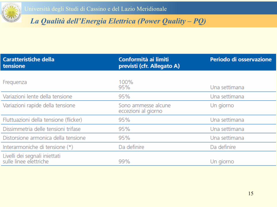
15
Universitagrave degli Studi di Cassino e del Lazio Meridionale
La Qualitagrave dellrsquoEnergia Elettrica (Power Quality ndash PQ)
16
17
Universitagrave degli Studi di Cassino e del Lazio Meridionale
La Qualitagrave dellrsquoEnergia Elettrica (Power Quality ndash PQ)
CURVA DI TOLLERANZA AI DISTURBI
18
Caratteristiche dellrsquoalimentazione a bassa tensione
Universitagrave degli Studi di Cassino e del Lazio Meridionale
La Qualitagrave dellrsquoEnergia Elettrica (Power Quality ndash PQ)
19
Caratteristiche dellrsquoalimentazione a bassa tensione
Frequenza nominale
La frequenza nominale della tensione fornita deve essere di 50 Hz In condizioni normali
di esercizio il valore medio misurato nellrsquointervallo di 10 secondi deve essere
Per i sistemi con collegamento sincrono ad un sistema interconnesso
1 50 Hz plusmn 1 durante il 95 di un anno
2 50 Hz +4 - 6 durante il 100 di un anno
Per i sistemi senza collegamento sincrono ad un sistema interconnesso
1 50 Hz plusmn 2 durante il 95 di un anno
2 50 Hz plusmn 15 durante il 100 di un anno
Universitagrave degli Studi di Cassino e del Lazio Meridionale
La Qualitagrave dellrsquoEnergia Elettrica (Power Quality ndash PQ)
20
Caratteristiche dellrsquoalimentazione a bassa tensione
Universitagrave degli Studi di Cassino e del Lazio Meridionale
La Qualitagrave dellrsquoEnergia Elettrica (Power Quality ndash PQ)
21
Caratteristiche dellrsquoalimentazione a bassa tensione
Universitagrave degli Studi di Cassino e del Lazio Meridionale
La Qualitagrave dellrsquoEnergia Elettrica (Power Quality ndash PQ)
22
Variazioni della tensione di alimentazione (variazioni lente)
Le variazioni lente sono deviazioni ldquomedierdquo dal valore nominale dellrsquoampiezza della
tensione di consegna entro una fascia predefinita (per esempio del plusmn10) rispetto alla
tensione dichiarata
CAUSE variazione lenta dei carichi e dalla corrispondente azione di regolazione effettuata dai
variatori sotto carico dei trasformatori
Universitagrave degli Studi di Cassino e del Lazio Meridionale
La Qualitagrave dellrsquoEnergia Elettrica (Power Quality ndash PQ)
23
Variazioni della tensione di alimentazione (variazioni rapide)
Le variazioni rapide sono abbassamenti (o aumenti) bruschi di qualche percento della
tensione preesistente generalmente seguiti se abbassamenti da un ritorno (a rampa o di
altra forma) ad un valore intermedio tra quello preesistente e tra il minimo raggiunto
CAUSE commutazione dei carichi (partenza motori in particolare) funzionamento di carichi
con ciclo operativo particolarmente variabile e in qualche caso da manovre in rete (linee
trasformatori condensatori ecc)
Universitagrave degli Studi di Cassino e del Lazio Meridionale
La Qualitagrave dellrsquoEnergia Elettrica (Power Quality ndash PQ)
24
Flicker Il flicker egrave originato dalla fluttuazione della tensione Si definisce fluttuazione di tensione una
serie di variazioni rapide (uguali o diverse) della tensione
Fluttuazioni di tensione che presentano frequenze di modulazione del 50 Hz comprese tra 05 e
40 Hz danno origine al fenomeno del flicker (sfarfallio) ovvero della sensazione visiva
provocata dalle fluttuazioni dellrsquointensitagrave di illuminazione delle lampade
I suoi principali effetti sullrsquouomo possono essere mal di testa irritabilitagrave e fastidio agli occhi
Universitagrave degli Studi di Cassino e del Lazio Meridionale
La Qualitagrave dellrsquoEnergia Elettrica (Power Quality ndash PQ)
25
Universitagrave degli Studi di Cassino e del Lazio Meridionale
La Qualitagrave dellrsquoEnergia Elettrica (Power Quality ndash PQ)
26
La Qualitagrave dellrsquoEnergia Elettrica (Power Quality ndash PQ)
Universitagrave degli Studi di Cassino e del Lazio Meridionale
La Qualitagrave dellrsquoEnergia Elettrica (Power Quality ndash PQ)
27
Universitagrave degli Studi di Cassino e del Lazio Meridionale
La Qualitagrave dellrsquoEnergia Elettrica (Power Quality ndash PQ)
28
Universitagrave degli Studi di Cassino e del Lazio Meridionale
La Qualitagrave dellrsquoEnergia Elettrica (Power Quality ndash PQ)
29
Universitagrave degli Studi di Cassino e del Lazio Meridionale
La Qualitagrave dellrsquoEnergia Elettrica (Power Quality ndash PQ)
30
Universitagrave degli Studi di Cassino e del Lazio Meridionale
La Qualitagrave dellrsquoEnergia Elettrica (Power Quality ndash PQ)
31
Universitagrave degli Studi di Cassino e del Lazio Meridionale
La Qualitagrave dellrsquoEnergia Elettrica (Power Quality ndash PQ)
32
Buchi di tensione Riduzione temporanea della tensione in un punto della rete elettrica sotto una determinata
soglia Se durante un buco la tensione scende sotto una soglia di interruzione lrsquoevento egrave
considerato essere sia un buco che unrsquointerruzione
CAUSE I buchi di tensione sono generalmente dovuti a guasti che sopravvengono negli
impianti utilizzatori o nel sistema di distribuzione pubblico Possono dipendere anche variazioni
di carico lungo la linea
Universitagrave degli Studi di Cassino e del Lazio Meridionale
La Qualitagrave dellrsquoEnergia Elettrica (Power Quality ndash PQ)
33
Interruzioni della tensione di alimentazione Condizione in cui la tensione ad un terminale della rete egrave inferiore allrsquo1 della tensione
nominale per una durata fino a tre minuti (brevi) o maggiori di 3 minuti (lunghe)
Universitagrave degli Studi di Cassino e del Lazio Meridionale
La Qualitagrave dellrsquoEnergia Elettrica (Power Quality ndash PQ)
34
Sovratensioni temporanee alla frequenza di rete fra fasi e terra Le sovratensioni sono sopraelevazioni della tensione conseguenti a modificazioni dello
stato elettrico della rete elettrica
Universitagrave degli Studi di Cassino e del Lazio Meridionale
La Qualitagrave dellrsquoEnergia Elettrica (Power Quality ndash PQ)
35
Armoniche Le armoniche sono tensioni o correnti sinusoidali con frequenza pari ad un multiplo intero
(ordine) della frequenza fondamentale di funzionamento del sistema elettrico la cui
presenza determina una distorsione della forma drsquoonda della tensione di alimentazione
CAUSE In piccola parte dal sistema stesso (trasformatori etc) e per la maggior parte da
apparecchi utilizzatori carichi commutati elettronicamente raddrizzatori convertitori regolatori
in AC cicloconvertitori ecc carichi con caratteristiche non lineari apparecchiature a
saturazione magnetica lampade a scarica forni ad arco saldatrici ad arco trasformatori ecc
bull carichi inseriti e disinseriti da organi di manovra condensatori filtri e motori a induzione
Universitagrave degli Studi di Cassino e del Lazio Meridionale
La Qualitagrave dellrsquoEnergia Elettrica (Power Quality ndash PQ)
36
Armoniche di tensione e corrente ndash Problemi
Vi sono diversi ambiti causati dalle armoniche
bull problemi causati da armoniche di corrente
1048707 sovraccarico del neutro
1048707 aumento delle perdite nei trasformatori
1048707 interventi intempestivi degli interruttori automatici
1048707 aumento dellrsquoeffetto pelle
bull problemi causati da armoniche di tensione
1048707 deformazione della tensione
1048707 disturbi nella coppia dei motori ad induzione
1048707 rumore al passaggio per lo zero
bull problemi causati quando le armoniche di corrente raggiungono lrsquoalimentazione
Universitagrave degli Studi di Cassino e del Lazio Meridionale
La Qualitagrave dellrsquoEnergia Elettrica (Power Quality ndash PQ)
37
38
Universitagrave degli Studi di Cassino e del Lazio Meridionale
La Qualitagrave dellrsquoEnergia Elettrica (Power Quality ndash PQ)
39
Strumentazione ldquohand heldrdquo con display
Universitagrave degli Studi di Cassino e del Lazio Meridionale
La Qualitagrave dellrsquoEnergia Elettrica (Power Quality ndash PQ)
40
Strumentazione ldquohand heldrdquo con display
Universitagrave degli Studi di Cassino e del Lazio Meridionale
La Qualitagrave dellrsquoEnergia Elettrica (Power Quality ndash PQ)
41
Strumentazione da registrazione
Universitagrave degli Studi di Cassino e del Lazio Meridionale
La Qualitagrave dellrsquoEnergia Elettrica (Power Quality ndash PQ)
42
Schema di principio ndash 61000-4-30 copy IEC2008
The electrical quantity to be measured may be either directly accessible as is
generally the case in low-voltage systems or accessible via measurement
transducers
An instrument may include the whole measurement chain In this standard the
normative part does not consider the measurement transducers external to the
instrument and their associated uncertainty
Universitagrave degli Studi di Cassino e del Lazio Meridionale
La Qualitagrave dellrsquoEnergia Elettrica (Power Quality ndash PQ)
43
Universitagrave degli Studi di Cassino Corso di Fondamenti di Misure
La Qualitagrave dellrsquoEnergia Elettrica (Power Quality ndash PQ)
Classi dei metodi di misura - 61000-4-30 copy IEC2008
For each class measurement methods and appropriate performance requirements
are included
Sono definite tre classi A S e B
Class A
This class is used where precise measurements are necessary for example for contractual
applications that may require resolving disputes verifying compliance with standards etc
Any measurements of a parameter carried out with two different instruments complying with
the requirements of Class A when measuring the same signals will produce matching results
within the specified uncertainty for that parameter
Class S
This class is used for statistical applications such as surveys or power quality assessment
possibly with a limited subset of parameters Although it uses equivalent intervals of
measurement as class A the class S processing requirements are lower
Class B
This class is defined in order to avoid making many existing instruments designs obsolete
NOTE Class B methods are not recommended for new designs Readers are advised that Class B may be removed in a
future Edition of this standard
44
Classi dei metodi di misura - 61000-4-30 copy IEC2008
Measurement aggregation over time intervals
CLASS A
The basic measurement time interval for parameter magnitudes (supply voltage harmonics
interharmonics and unbalance) shall be a 10-cycle time interval for a 50 Hz power system
or 12-cycle time interval for a 60 Hz power system
The 1012-cycle measurement shall be re-synchronized at every RTC 10 min tick
The 1012-cycle values are then aggregated over 3 additional intervals
ndash 150180-cycle interval (150 cycles for 50 Hz nominal or 180 cycles for 60 Hz nominal)
ndash 10 min interval
ndash 2 h interval
CLASS S
Same time intervals as Class A
CLASS B
The manufacturer shall specify the number and duration of aggregation time intervals
Universitagrave degli Studi di Cassino e del Lazio Meridionale
La Qualitagrave dellrsquoEnergia Elettrica (Power Quality ndash PQ)
45
Universitagrave degli Studi di Cassino e del Lazio Meridionale
La Qualitagrave dellrsquoEnergia Elettrica (Power Quality ndash PQ)
46
Universitagrave degli Studi di Cassino e del Lazio Meridionale
La Qualitagrave dellrsquoEnergia Elettrica (Power Quality ndash PQ)
Class A
The 10-min aggregated value shall be tagged with the absolute time (for
example 01H1000) The time tag is the time at the conclusion of the 10-min
aggregation
The data for the 10-min time interval shall be aggregated from 1012-cycle time
intervals
Each 10-minute interval shall begin on a UTC 10-min tick The 10-min tick is
also used to re-synchronize the 1012-cycle intervals and the 150180-cycle
intervals
The final 1012-cycle interval(s) in a 10-min aggregation period will typically
overlap in time with the UTC 10-min clock tick Any overlapping 1012-cycle
interval (Overlap 1 in Figure 2) is included in the aggregation of the previous
10-min interval
47
Universitagrave degli Studi di Cassino e del Lazio Meridionale
La Qualitagrave dellrsquoEnergia Elettrica (Power Quality ndash PQ)
48
Universitagrave degli Studi di Cassino e del Lazio Meridionale
La Qualitagrave dellrsquoEnergia Elettrica (Power Quality ndash PQ)
49
Classi dei metodi di misura - 61000-4-30 copy IEC2008
Real time clock (RTC) uncertainty
Sono definite le specifiche per le 3 classi
Flagging concept
During a dip swell or interruption the measurement algorithm for other
parameters (for example frequency measurement) might produce an unreliable
value The flagging concept therefore avoids counting a single event more than
once in different parameters (for example counting a single dip as both a dip and a
frequency variation) and indicates that an aggregated value might be unreliable
Universitagrave degli Studi di Cassino e del Lazio Meridionale
La Qualitagrave dellrsquoEnergia Elettrica (Power Quality ndash PQ)
50
Classi dei metodi di misura - 61000-4-30 copy IEC2008
Power quality parameters - INDICES
Per ogni parametro viene suggerito il metodo di misura per le tre classi e
(soprattutto) le caratteristiche di precisione Per alcuni parametri rimanda a
specifiche norme (ad esempio Flicker e Armonicheinterarmoniche)
Esempio - Power frequency Class A
The frequency reading shall be obtained every 10 s As power frequency may not be exactly 50 Hz or 60
Hz within the 10 s time clock interval the number of cycles may not be an integer number The
fundamental frequency output is the ratio of the number of integral cycles counted during the 10 s time
clock interval divided by the cumulative duration of the integer cycles Before each assessment
harmonics and interharmonics shall be attenuated to minimize the effects of multiple zero crossings
The measurement time intervals shall be non-overlapping Individual cycles that overlap the 10 s time
clock are discarded Each 10 s interval shall begin on an absolute 10 s time clock with uncertainty as
defined in 46
Other techniques that provide equivalent results such as convolution are acceptable
Class S Same as class A
Class B The manufacturer shall specify the process used for frequency measurement
Universitagrave degli Studi di Cassino e del Lazio Meridionale
La Qualitagrave dellrsquoEnergia Elettrica (Power Quality ndash PQ)
51
Classi dei metodi di misura - 61000-4-30 copy IEC2008
Power quality parameters - INDICES
Per ogni parametro viene suggerito il metodo di misura per le tre classi e
(soprattutto) le caratteristiche di precisione Per alcuni parametri rimanda a
specifiche norme (ad esempio Flicker e Armonicheinterarmoniche)
Esempio - Power frequency
Measurement uncertainty and measuring range
ndash Class A
Under the conditions described in 61 the measurement uncertainty shall not exceed
plusmn10 mHz over the measuring ranges 425 Hz ~ 575 Hz 51 Hz ~ 69 Hz
ndash Class S
Under the conditions described in 61 the measurement uncertainty shall not exceed
plusmn50 mHz over the measuring ranges 425 Hz ~ 575 Hz 51 Hz ~ 69 Hz
ndash Class B
The manufacturer shall specify the uncertainty over the measuring ranges 425 Hz ~
575 Hz 51 Hz ~ 69 Hz
Universitagrave degli Studi di Cassino e del Lazio Meridionale
La Qualitagrave dellrsquoEnergia Elettrica (Power Quality ndash PQ)
52
Magnitude of the supply voltage
Measurement method
ndash Class A
The measurement shall be the rms value of the voltage magnitude over
a 10-cycle time interval for 50 Hz power system or 12-cycle time
interval for 60 Hz power system Every 1012-cycle interval shall be
contiguous and not overlapping with adjacent 1012-cycle intervals
except as shown as Overlap 1 in Figure 2
NOTE 1 This specific measurement method is used for quasi-stationary signals and is
not used for the detection and measurement of disturbances dips swells voltage
interruptions and transients
NOTE 2 The rms value includes by definition harmonics interharmonics mains
signalling etc
- Class S same as Class A
Universitagrave degli Studi di Cassino e del Lazio Meridionale
La Qualitagrave dellrsquoEnergia Elettrica (Power Quality ndash PQ)
53
Magnitude of the supply voltage
Measurement uncertainty and measuring range
ndash Class A
Under the conditions described in Clause 6 the measurement uncertainty
shall not exceed plusmn01 of Udin over the range of 10 ~ 150 of Udin
ndash Class S
Under the conditions described in Clause 6 the measurement uncertainty
shall not exceed plusmn05 of Udin over the range of 20 ~ 120 of Udin
Universitagrave degli Studi di Cassino e del Lazio Meridionale
La Qualitagrave dellrsquoEnergia Elettrica (Power Quality ndash PQ)
54
Supply voltage dips and swells
Measurement method
ndash Class A
The basic measurement Urms of a voltage dip and swell shall be the
Urms(frac12) on each measurement channel (see Clause 322)
The cycle duration for Urms(frac12) depends on the frequency The
frequency might be determined by the last non-flagged power frequency
measurement (see Clause 47 and Clause 51) or by any other method
that yields the uncertainty requirements of Clause 6
NOTE 1 The Urms(frac12) value includes by definition harmonics interharmonics mains
signalling voltage etc
NOTE 2 It is important to avoid loss of data when dips and swells occur in a rapid
sequence (for example three events in one second with up to one minute between
sequences may occur when a recloser operates into a sustained fault) If during a rapid
burst the dipswell event characteristics cannot be recorded then a count of events may
be useful
Universitagrave degli Studi di Cassino e del Lazio Meridionale
La Qualitagrave dellrsquoEnergia Elettrica (Power Quality ndash PQ)
55
Supply voltage dips and swells
Detection and evaluation of a voltage dip
Voltage dip detection
The dip threshold is a percentage of either Udin or the sliding voltage
reference Usr (see 525 544) The user shall declare the reference
voltage in use
NOTE ndash On single-phase systems a voltage dip begins when the Urms voltage falls
below the dip threshold and ends when the Urms voltage is equal to or above the dip
threshold plus the hysteresis voltage
ndash On polyphase systems a dip begins when the Urms voltage of one or more channels is
below the dip threshold and ends when the Urms voltage on all measured channels is
equal to or above the dip threshold plus the hysteresis voltage
The dip threshold and the hysteresis voltage are both set by the user according to the
use
Universitagrave degli Studi di Cassino e del Lazio Meridionale
La Qualitagrave dellrsquoEnergia Elettrica (Power Quality ndash PQ)
56
Calculation of a sliding reference voltage
The sliding reference voltage implementation is optional not mandatory
If a sliding reference is chosen for voltage dip or swell detection this
shall be calculated using a first-order filter with a 1-min time constant
This filter is given by
Usr(n) = 09967 times Usr(nndash1) + 00033 times U(1012)rms
where
Usr(n) is the present value of the sliding reference voltage
Usr(nndash1) is the previous value of the sliding reference voltage and
U(1012)rms is the most recent 1012-cycle rms value
When the measurement is started the initial value of the sliding reference voltage is set
to the declared input voltage The sliding reference voltage is updated every 1012-
cycles If a 1012-cycle value is flagged the sliding reference voltage is not updated
and the previous value is used
Universitagrave degli Studi di Cassino e del Lazio Meridionale
La Qualitagrave dellrsquoEnergia Elettrica (Power Quality ndash PQ)
57
Supply voltage dips and swells
Voltage dip evaluation
A voltage dip is characterized by a pair of data either residual voltage
(Ures) or depth and duration
ndash the residual voltage of a voltage dip is the lowest Urms(frac12) value
measured on any channel during the dip
ndash the depth is the difference between the reference voltage (either Udin
or Usr) and the residual voltage It is generally expressed in percentage
of the reference voltage
NOTE 1 During the dip it may be useful to also record the lowest Urms(frac12) on each
channel in addition to the residual voltage of the dip The duration spent below the dip
threshold on each channel may also be useful
Universitagrave degli Studi di Cassino e del Lazio Meridionale
La Qualitagrave dellrsquoEnergia Elettrica (Power Quality ndash PQ)
58
Supply voltage dips and swells
Voltage dip evaluation
NOTE 2 If voltage waveforms are recorded before during and after a
dip useful information about phase angle changes may be available in
the recorded data
The start time of a dip shall be time stamped with the time of the start of
the Urms of the channel that initiated the event and the end time of the
dip shall be the time stamped with the time of the end of the Urms that
ended the event as defined by the threshold plus the hysteresis
The duration of a voltage dip is the time difference between the start
time and the end time of the voltage dip
Universitagrave degli Studi di Cassino e del Lazio Meridionale
La Qualitagrave dellrsquoEnergia Elettrica (Power Quality ndash PQ)
59
Supply voltage dips and swells
Residual voltage and swell voltage magnitude measurement
uncertainty
ndash Class A
The measurement uncertainty shall not exceed plusmn02 of Udin
ndash Class S
The measurement uncertainty shall not exceed plusmn10 of Udin
Universitagrave degli Studi di Cassino e del Lazio Meridionale
La Qualitagrave dellrsquoEnergia Elettrica (Power Quality ndash PQ)
60
Schema di principio ndash 61000-4-7 copy IEC2002
Universitagrave degli Studi di Cassino e del Lazio Meridionale
La Qualitagrave dellrsquoEnergia Elettrica (Power Quality ndash PQ)
61
Universitagrave degli Studi di Cassino e del Lazio Meridionale
La Qualitagrave dellrsquoEnergia Elettrica (Power Quality ndash PQ)
62
Universitagrave degli Studi di Cassino e del Lazio Meridionale
La Qualitagrave dellrsquoEnergia Elettrica (Power Quality ndash PQ)
63
Inter-Armoniche Le inter-armoniche sono tensioni o correnti sinusoidali con frequenza diversa da un
multiplo intero della fondamentale la cui presenza determina una distorsione
(modulazione) della forma donda della tensione di alimentazione
CAUSE dai carichi che assorbono correnti inter-armoniche
- carichi commutati elettronicamente convertitori cascata subsincrona cicloconvertitori regolatori con
controllo a pacchetti di cicli ecc
- carichi con caratteristiche non lineari eo non stazionarie forni ad arco saldatrici ad arco ecc
Universitagrave degli Studi di Cassino e del Lazio Meridionale
La Qualitagrave dellrsquoEnergia Elettrica (Power Quality ndash PQ)
64
Universitagrave degli Studi di Cassino e del Lazio Meridionale
La Qualitagrave dellrsquoEnergia Elettrica (Power Quality ndash PQ)
Un porsquo di esempi e
consigli praticihellip
65
0V
50V
100V
150V
200V
250V
300V
350V
0ms 5ms 10ms 15ms 20ms
t
u
0A
1A
2A
3A
i
0V
50V
100V
150V
200V
250V
300V
350V
0ms 5ms 10ms 15ms 20ms
t
u
0A
1A
2A
3A
i
0V
50V
100V
150V
200V
250V
300V
350V
0ms 5ms 10ms 15ms 20ms
t
u
0A
1A
2A
3A
i
gleichgerichtete
Netzspannung
Kondensator-
spannung
gleichgerichteter
Netzstrom
The situation
today
bull Computed current and voltage profiles when a
230 V 58 W fluorescent lamp with an old-style
electronic ballast is driven on the phase wire of
a typical power distribution system
System voltage 230 V
System frequency 50 Hz
Source resistance 500 mW
Longitudinal induction 904 microH
System impedance 575 mW
Mean dc current 180 mA
Smoothing capacitance220 microF
66
And what about electronic ballasts that are rated over 25W
Introduce electronic power factor correction (PFC)
0V
20V
40V
60V
80V
100V
120V
140V
160V
180V
200V
220V
0deg 15deg 30deg 45deg
u
00A
03A
06A
09A
12A
i
67
Though todayrsquos ballasts are better if
rated gt25 W bull Only
the
small
ones
continu
e to
pollute
just like
PCs
TV sets
do
68
This leads to a number of
previously unknown effects bull 1 Deformed voltage curves
bull 2 Huge inrush current peaks
bull 3 Instrument dependent measured parameters
bull 4 Increased loading of phase conductors
bull 5 Loading and overloading of the neutral conductor
bull 6 Overheating and start-up problems of induction motors
bull 7 Additional stray losses in transformers
bull 8 Repercussions of generators upon the mains
bull 9 Influence of capacitors repercussions upon the mains
and four additional complications in TN-C systems
10 Stray currents in equipotential bonding system magnetic fields
11 Contamination of data streams by stray currents
12 Stray currents in the earthing system corrosion damage
13 Lightning currents in devices and equipment
69
1 Deformed voltage curves
bull in theory
-350V
-300V
-250V
-200V
-150V
-100V
-50V
0V
50V
100V
150V
200V
250V
300V
350V
0 5 10 15 20
t ms
u
System voltage profile when driving
a single-phase load comprising
twenty 58 W energy-saver lamps in
parallel on a typical 230 V power
system
70
and in practice
bull An actual
current profile
bull
bull and
bull a voltage profile
bull
bull recorded in a large storage
dispatch and administrative
building
71
at home or in industrial environments
bull
bull Television 40
W
bull 200 Vdiv 2
Adiv
bull 5 msdiv
Harmonic
spectrum
Frequency
converter
50 Adiv
Phase currents
I1=I2=I3=160 A
IN=295 A
5 msdiv
72
Every periodic waveform can be written
as the infinite sum of sinusoidal waves
-175
-150
-125
-100
-75
-50
-25
0
25
50
75
100
125
150
175
0 5 10 15 20
t ms
i
mA
itot
i1
Synthesis of a triangular current profile 100mA
Content fundamental I = 99 mA Isup2 = 9855 mAsup2
Sum of squares Isup2 = 9855 mAsup2
Root of sum = RMS value I = 99 mA
-175
-150
-125
-100
-75
-50
-25
0
25
50
75
100
125
150
175
0 5 10 15 20
t ms
i
mA
itot
i1
i3
Synthesis of a triangular current profile 100mA
Content fundamental I = 99 mA Isup2 = 9855 mAsup2
Cont 3 rd harmonic I = -11 mA Isup2 = 122 mAsup2
Sum of squares Isup2 = 9977 mAsup2
Root of sum = RMS value I = 100 mA
-175
-150
-125
-100
-75
-50
-25
0
25
50
75
100
125
150
175
0 5 10 15 20
t ms
i
mA
itot
i1
i3
i5
Synthesis of a triangular current profile 100mA
Content fundamental I = 99 mA Isup2 = 9855 mAsup2
Cont 3 rd harmonic I = -11 mA Isup2 = 122 mAsup2
Cont 5 th harmonic I = 4 mA Isup2 = 16 mAsup2
Sum of squares Isup2 = 9993 mAsup2
Root of sum = RMS value I = 100 mA
-175
-150
-125
-100
-75
-50
-25
0
25
50
75
100
125
150
175
0 5 10 15 20
t ms
i
mA
itot
i1
i3
i5
i7
Synthesis of a triangular current profile 100mA
Content fundamental I = 99 mA Isup2 = 9855 mAsup2
Cont 3 rd harmonic I = -11 mA Isup2 = 122 mAsup2
Cont 5 th harmonic I = 4 mA Isup2 = 16 mAsup2
Cont 7 th harmonic I = -2 mA Isup2 = 4 mAsup2
Sum of squares Isup2 = 9997 mAsup2
Root of sum = RMS value I = 100 mA
-175
-150
-125
-100
-75
-50
-25
0
25
50
75
100
125
150
175
0 5 10 15 20
t ms
i
mA
itot i1
i3 i5
i7 i9
Synthesis of a triangular current profile 100mA
Content fundamental I = 99 mA Isup2 = 9855 mAsup2
Cont 3 rd harmonic I = -11 mA Isup2 = 122 mAsup2
Cont 5 th harmonic I = 4 mA Isup2 = 16 mAsup2
Cont 7 th harmonic I = -2 mA Isup2 = 4 mAsup2
Cont 9 th harmonic I = 1 mA Isup2 = 2 mAsup2
Sum of squares Isup2 = 9998 mAsup2
Root of sum = RMS value I = 100 mA
-175
-150
-125
-100
-75
-50
-25
0
25
50
75
100
125
150
175
0 5 10 15 20
t ms
i
mA
itot i1
i3 i5
i7 i9
i11
Synthesis of a triangular current profile 100mA
Content fundamental I = 99 mA Isup2 = 9855 mAsup2
Cont 3 rd harmonic I = -11 mA Isup2 = 122 mAsup2
Cont 5 th harmonic I = 4 mA Isup2 = 16 mAsup2
Cont 7 th harmonic I = -2 mA Isup2 = 4 mAsup2
Cont 9 th harmonic I = 1 mA Isup2 = 2 mAsup2
Cont 11 th harmonic I = -1 mA Isup2 = 1 mAsup2
Sum of squares Isup2 = 9999 mAsup2
Root of sum = RMS value I = 100 mA
-175
-150
-125
-100
-75
-50
-25
0
25
50
75
100
125
150
175
0 5 10 15 20
t ms
i
mA
itot i1
i3 i5
i7 i9
i11 i13
Synthesis of a triangular current profile 100mA
Content fundamental I = 99 mA Isup2 = 9855 mAsup2
Cont 3 rd harmonic I = -11 mA Isup2 = 122 mAsup2
Cont 5 th harmonic I = 4 mA Isup2 = 16 mAsup2
Cont 7 th harmonic I = -2 mA Isup2 = 4 mAsup2
Cont 9 th harmonic I = 1 mA Isup2 = 2 mAsup2
Cont 11 th harmonic I = -1 mA Isup2 = 1 mAsup2
Cont 13 th harmonic I = 1 mA Isup2 = 0 mAsup2
Sum of squares Isup2 = 9999 mAsup2
Root of sum = RMS value I = 100 mA
-175
-150
-125
-100
-75
-50
-25
0
25
50
75
100
125
150
175
0 5 10 15 20
t ms
i
mA
itot i1
i3 i5
i7 i9
i11 i13
i15
Synthesis of a triangular current profile 100mA
Content fundamental I = 99 mA Isup2 = 9855 mAsup2
Cont 3 rd harmonic I = -11 mA Isup2 = 122 mAsup2
Cont 5 th harmonic I = 4 mA Isup2 = 16 mAsup2
Cont 7 th harmonic I = -2 mA Isup2 = 4 mAsup2
Cont 9 th harmonic I = 1 mA Isup2 = 2 mAsup2
Cont 11 th harmonic I = -1 mA Isup2 = 1 mAsup2
Cont 13 th harmonic I = 1 mA Isup2 = 0 mAsup2
Cont 15 th harmonic I = 0 mA Isup2 = 0 mAsup2
Sum of squares Isup2 = 10000 mAsup2
Root of sum = RMS value I = 100 mA
-175
-150
-125
-100
-75
-50
-25
0
25
50
75
100
125
150
175
0 5 10 15 20
t ms
i
mA
itot i1
i3 i5
i7 i9
i11 i13
i15 i17
Synthesis of a triangular current profile 100mA
Content fundamental I = 99 mA Isup2 = 9855 mAsup2
Cont 3 rd harmonic I = -11 mA Isup2 = 122 mAsup2
Cont 5 th harmonic I = 4 mA Isup2 = 16 mAsup2
Cont 7 th harmonic I = -2 mA Isup2 = 4 mAsup2
Cont 9 th harmonic I = 1 mA Isup2 = 2 mAsup2
Cont 11 th harmonic I = -1 mA Isup2 = 1 mAsup2
Cont 13 th harmonic I = 1 mA Isup2 = 0 mAsup2
Cont 15 th harmonic I = 0 mA Isup2 = 0 mAsup2
Cont 17 th harmonic I = 0 mA Isup2 = 0 mAsup2
Sum of squares Isup2 = 10000 mAsup2
Root of sum = RMS value I = 100 mA
73
whose frequencies called harmonics are
integer multiples of the fundamental frequency
-175
-150
-125
-100
-75
-50
-25
0
25
50
75
100
125
150
175
0 5 10 15 20
t ms
i
mA
itot
i1
Synthesis of a rectangular current profile 100mA
Content fundamental I = 90 mA Isup2 = 8106 mAsup2
Sum of squares Isup2 = 8106 mAsup2
Root of sum = RMS value I = 90 mA
-175
-150
-125
-100
-75
-50
-25
0
25
50
75
100
125
150
175
0 5 10 15 20
t ms
i
mA
itot
i1
i3
Synthesis of a rectangular current profile 100mA
Content fundamental I = 90 mA Isup2 = 8106 mAsup2
Cont 3 rd harmonic I = 30 mA Isup2 = 901 mAsup2
Sum of squares Isup2 = 9006 mAsup2
Root of sum = RMS value I = 95 mA
-175
-150
-125
-100
-75
-50
-25
0
25
50
75
100
125
150
175
0 5 10 15 20
t ms
i
mA
itot
i1
i3
i5
Synthesis of a rectangular current profile 100mA
Content fundamental I = 90 mA Isup2 = 8106 mAsup2
Cont 3 rd harmonic I = 30 mA Isup2 = 901 mAsup2
Cont 5 th harmonic I = 18 mA Isup2 = 324 mAsup2
Sum of squares Isup2 = 9331 mAsup2
Root of sum = RMS value I = 97 mA
-175
-150
-125
-100
-75
-50
-25
0
25
50
75
100
125
150
175
0 5 10 15 20
t ms
i
mA
itot
i1
i3
i5
i7
Synthesis of a rectangular current profile 100mA
Content fundamental I = 90 mA Isup2 = 8106 mAsup2
Cont 3 rd harmonic I = 30 mA Isup2 = 901 mAsup2
Cont 5 th harmonic I = 18 mA Isup2 = 324 mAsup2
Cont 7 th harmonic I = 13 mA Isup2 = 165 mAsup2
Sum of squares Isup2 = 9496 mAsup2
Root of sum = RMS value I = 97 mA
-175
-150
-125
-100
-75
-50
-25
0
25
50
75
100
125
150
175
0 5 10 15 20
t ms
i
mA
itot i1
i3 i5
i7 i9
Synthesis of a rectangular current profile 100mA
Content fundamental I = 90 mA Isup2 = 8106 mAsup2
Cont 3 rd harmonic I = 30 mA Isup2 = 901 mAsup2
Cont 5 th harmonic I = 18 mA Isup2 = 324 mAsup2
Cont 7 th harmonic I = 13 mA Isup2 = 165 mAsup2
Cont 9 th harmonic I = 10 mA Isup2 = 100 mAsup2
Sum of squares Isup2 = 9596 mAsup2
Root of sum = RMS value I = 98 mA
-175
-150
-125
-100
-75
-50
-25
0
25
50
75
100
125
150
175
0 5 10 15 20
t ms
i
mA
itot i1
i3 i5
i7 i9
i11
Synthesis of a rectangular current profile 100mA
Content fundamental I = 90 mA Isup2 = 8106 mAsup2
Cont 3 rd harmonic I = 30 mA Isup2 = 901 mAsup2
Cont 5 th harmonic I = 18 mA Isup2 = 324 mAsup2
Cont 7 th harmonic I = 13 mA Isup2 = 165 mAsup2
Cont 9 th harmonic I = 10 mA Isup2 = 100 mAsup2
Cont 11 th harmonic I = 8 mA Isup2 = 67 mAsup2
Sum of squares Isup2 = 9663 mAsup2
Root of sum = RMS value I = 98 mA
-175
-150
-125
-100
-75
-50
-25
0
25
50
75
100
125
150
175
0 5 10 15 20
t ms
i
mA
itot i1
i3 i5
i7 i9
i11 i13
Synthesis of a rectangular current profile 100mA
Content fundamental I = 90 mA Isup2 = 8106 mAsup2
Cont 3 rd harmonic I = 30 mA Isup2 = 901 mAsup2
Cont 5 th harmonic I = 18 mA Isup2 = 324 mAsup2
Cont 7 th harmonic I = 13 mA Isup2 = 165 mAsup2
Cont 9 th harmonic I = 10 mA Isup2 = 100 mAsup2
Cont 11 th harmonic I = 8 mA Isup2 = 67 mAsup2
Cont 13 th harmonic I = 7 mA Isup2 = 48 mAsup2
Sum of squares Isup2 = 9711 mAsup2
Root of sum = RMS value I = 99 mA
-175
-150
-125
-100
-75
-50
-25
0
25
50
75
100
125
150
175
0 5 10 15 20
t ms
i
mA
itot i1
i3 i5
i7 i9
i11 i13
i15
Synthesis of a rectangular current profile 100mA
Content fundamental I = 90 mA Isup2 = 8106 mAsup2
Cont 3 rd harmonic I = 30 mA Isup2 = 901 mAsup2
Cont 5 th harmonic I = 18 mA Isup2 = 324 mAsup2
Cont 7 th harmonic I = 13 mA Isup2 = 165 mAsup2
Cont 9 th harmonic I = 10 mA Isup2 = 100 mAsup2
Cont 11 th harmonic I = 8 mA Isup2 = 67 mAsup2
Cont 13 th harmonic I = 7 mA Isup2 = 48 mAsup2
Cont 15 th harmonic I = 6 mA Isup2 = 36 mAsup2
Sum of squares Isup2 = 9747 mAsup2
Root of sum = RMS value I = 99 mA
-175
-150
-125
-100
-75
-50
-25
0
25
50
75
100
125
150
175
0 5 10 15 20
t ms
i
mA
itot i1
i3 i5
i7 i9
i11 i13
i15 i17
Synthesis of a rectangular current profile 100mA
Content fundamental I = 90 mA Isup2 = 8106 mAsup2
Cont 3 rd harmonic I = 30 mA Isup2 = 901 mAsup2
Cont 5 th harmonic I = 18 mA Isup2 = 324 mAsup2
Cont 7 th harmonic I = 13 mA Isup2 = 165 mAsup2
Cont 9 th harmonic I = 10 mA Isup2 = 100 mAsup2
Cont 11 th harmonic I = 8 mA Isup2 = 67 mAsup2
Cont 13 th harmonic I = 7 mA Isup2 = 48 mAsup2
Cont 15 th harmonic I = 6 mA Isup2 = 36 mAsup2
Cont 17 th harmonic I = 5 mA Isup2 = 28 mAsup2
Sum of squares Isup2 = 9775 mAsup2
Root of sum = RMS value I = 99 mA
74
Even far better simulations are
available free of charge at
bull wwwpowerstandardscomMcEachern
75
-4A
-3A
-2A
-1A
0A
1A
2A
3A
4A
0ms 5ms 10ms 15ms 20ms
t
i
-4A
-3A
-2A
-1A
0A
1A
2A
3A
4A
0ms 5ms 10ms 15ms 20ms
t
i
Applying the Fourier
analysis to a real PC
current does not work
directly
bull
bull but it can be
modelled by a similar
triangular curve in
which not all of the
higher harmonics
have been included
Triangular current profile of
the same amplitude and a
pulse duty cycle of 17
Input current of a PC
with monitor
76
Analysis of the model triangular waveform
-400
-350
-300
-250
-200
-150
-100
-50
0
50
100
150
200
250
300
350
400
0 5 10 15 20
t ms
iI
itot(t) L1 [A] i1(t) L1 [A]
i3(t) L1 [A] i5(t) L1 [A]
i7(t) L1 [A] i9(t) L1 [A]
i11(t) L1 [A] i13(t) L1 [A]
i15(t) L1 [A] i17(t) L1 [A]
77
M3
Harmonics
Energy
(active
power)
L1
L2
L3
N
PE
Important
bull Harmonics are created within the loads
themselves and can flow ldquoupstreamrdquo to
contaminate the power system
78
-6A
-5A
-4A
-3A
-2A
-1A
0A
1A
2A
3A
4A
5A
6A
0ms 5ms 10ms 15ms 20ms
t
i
Squared values
Without
Fundamental 502 mA 251986 mAsup2 the fundamental
3rd harmonic -479 mA 229000 mAsup2 229000 mAsup2
5th harmonic 434 mA 188595 mAsup2 188595 mAsup2
7th harmonic -374 mA 139903 mAsup2 139903 mAsup2
9th harmonic 304 mA 92527 mAsup2 92527 mAsup2
11th harmonic -232 mA 53671 mAsup2 53671 mAsup2
13th harmonic 163 mA 26600 mAsup2 26600 mAsup2
15th harmonic -104 mA 10780 mAsup2 10780 mAsup2
17th harmonic 57 mA 3299 mAsup2 3299 mAsup2
Sum of the squares 996362 mAsup2 744377 mAsup2
Root thereof 998 mAeff THD = 863 mA
What actually is THD Example shown here triangular current
profile with an rms current of 1000 mA
and a pulse duty cycle of 17
THDr (root mean square) = 863mA1000mA = 86
THDf (fundamental) = 863mA502mA = 172
79
Effect on phase-to-neutral
and phase-to-phase voltages
bull Recorded
on June
30 2002
230 p
m
bull What
was the
matter
then
bull The
soccer
final
Germany
vs
Brazil
80
The triple-N harmonics drive
a circulating current in the
delta winding of a distribution
transformer
bull but the
bull voltage harmonics
propagate into the next
low-voltage power
distribution system
81 0V
50V
100V
150V
200V
250V
300V
350V
400V
450V
500V
550V
0 10 20 30 40 50
t ms
u
0A
10A
20A
30A
40A
50A
60A
70A
80A
90A
100A
110A
120A
130A
140A
150A
i
Switching on just as supply voltage passes through zero
0V
50V
100V
150V
200V
250V
300V
350V
400V
450V
500V
550V
0 10 20 30 40 50
t ms
u
0A
10A
20A
30A
40A
50A
60A
70A
80A
90A
100A
110A
120A
130A
140A
150A
i
Switching on just as supply voltage is at its peak
2 Huge inrush current peaks
ndash in theory
82
and in practice
bull Inrush current of a
compact energy-
saver lamp and its
effect on the system
voltage (recorded at
the Technical
University of
Budapest)
bull
83
enables us to infer what
happens when run by a
normal three-phase supply
The same fluorescent lamp
with a magnetic ballast
bull The behaviour measured
when connected to
a dc supply
bull
Behaviour of a 58 W fluorescent lamp connected to a dc
supply
0
20
40
60
80
100
120
140
160
180
200
0 200 400 600 800 1000 1200
i mA
u
V
Measurement
Behaviour of a 58 W fluorescent lamp connected to a dc
supply
0
20
40
60
80
100
120
140
160
180
200
0 200 400 600 800 1000 1200
i mA
u
V
MeasurementCalculation
-350
-300
-250
-200
-150
-100
-50
0
50
100
150
200
250
300
350
0 5 10 15 20
t ms
u
V
-10
-08
-06
-04
-02
00
02
04
06
08
10
i
A
Systems voltage
Current
-350
-300
-250
-200
-150
-100
-50
0
50
100
150
200
250
300
350
0 5 10 15 20
t ms
u
V
-10
-08
-06
-04
-02
00
02
04
06
08
10
i
A
Systems voltage
Lamp voltage
Current
84
Warning ldquoCompensationrdquo is not
always what you think it is
bull Distinguish
between
bull Reactive
power
compensatio
n
aka power
factor
correction
Remedial
measure
Parallel (or
sometimes series)
compensation
using capacitors
Filter circuits
tuned to the
individual harmonic
frequencies
Harmonic
compensation
85
5 (Over)loading the neutral conductor
bull Magnetic ballast Old-style electronic ballast
-25A
-20A
-15A
-10A
-05A
00A
05A
10A
15A
20A
25A
0 5 10 15 20
t ms i
i(t) N
-25A
-20A
-15A
-10A
-05A
00A
05A
10A
15A
20A
25A
0 5 10 15 20
t ms
i
i(t) N
-25A
-20A
-15A
-10A
-05A
00A
05A
10A
15A
20A
25A
0 5 10 15 20
t ms
i
i(t) L1 i(t) L2 i(t) L3
-25A
-20A
-15A
-10A
-05A
00A
05A
10A
15A
20A
25A
0 5 10 15 20
t ms
i
i(t) L1
i(t) L2
i(t) L3
86
Adding the 3rd
harmonics
in the
neutral
wire
-150-100-50
050
100150
0deg 30deg 60deg 90deg 120deg 150deg 180deg 210deg 240deg 270deg 300deg 330deg 360deg
L1
-150-100-50
050
100150
0deg 30deg 60deg 90deg 120deg 150deg 180deg 210deg 240deg 270deg 300deg 330deg 360deg
L2
-150-100-50
050
100150
0deg 30deg 60deg 90deg 120deg 150deg 180deg 210deg 240deg 270deg 300deg 330deg 360deg
L3
-450-400-350-300-250-200-150-100-50
050
100150200250300350400450
0deg 30deg 60deg 90deg 120deg 150deg 180deg 210deg 240deg 270deg 300deg 330deg 360deg
f
iicirc
N
Physics dictates
that at any
moment in time
the phase and
neutral currents
must sum to zero
87
Effect on a three-phase ac motor
appears almost identical
bull The same motor is being
driven
simultaneously in
these three modes
homopolar system
zero-sequence system
direct system
positive-sequence system
inverse system
negative-sequence system
88
The transformer
influences the load
89
but the load also effects
the transformer
Total transformer loss is
2
)()(
nom
nomCunomFeLossI
IPPP
While total transformer loss really is
2
)(
2
)(
2
)(
nomnom
nomad
nom
nomCu
nom
nomFeLossI
I
f
fP
I
IP
U
UPP
90
6 ldquosupplementaryrdquo additional losses
in transformers
can be calculated rapidly
using the following two
simple formulae 50
2
2
1
2
11
Nn
n
nqh
I
In
I
I
e
eK
50
1
2
1
1
50
1
2
Nn
n
nNn
n
nI
IIII
where
Oh well
perhaps a practical
example is clearer
1000 compact 11W
(15VA) energy-saver
lamps powered by a
15kVA transformer
uSC=4 Pa=01PCu
Harmonics of an Osram Dulux 11W
CFL and a serial impedance of
R =291Ω amp X L=113Ω
U U sup2 I L I Lsup2 P aP Cu
n V Vsup2 mA mAsup2
1 2302 529920 485 23523 56
3 83 689 371 13764 295
5 107 1145 203 4121 245
7 43 185 53 281 33
9 11 12 30 90 17
11 23 53 38 144 42
13 10 10 15 23 09
15 06 04 15 23 12
17 11 12 15 23 15
19 05 03 09 08 07
21 05 03 13 17 18
23 06 04 08 06 08
25 04 02 06 04 05
27 06 04 08 06 11
29 04 02 05 03 05
31 03 01 05 03 06
33 03 01 05 03 06
35 03 01 04 02 05
37 03 01 04 02 05
39 03 01 03 01 03
41 01 00 03 01 04
43 02 00 02 00 02
45 01 00 02 00 02
47 01 00 02 00 02
49 01 00 01 00 01
51 01 00 01 00 01
P aP Cu = 814814
etc
etc
91
Harmonics measurement on an
Osram Dulux 11W compact
fluorescent lamp
U U sup2 I L I Lsup2 P addP Cu
n V Vsup2 mA mAsup2
1 2327 541493 489 23912 37
3 06 04 391 15288 215
5 44 194 264 6970 273
7 23 53 200 4000 307
9 01 00 192 3686 467
11 01 00 166 2756 522
13 01 00 127 1613 427
15 01 00 110 1210 426
17 01 00 102 1040 471
19 01 00 87 757 428
21 01 00 77 593 409
23 01 00 73 533 441
25 01 00 61 372 364
27 01 00 49 240 274
29 01 00 42 176 232
31 01 00 36 130 195
33 01 00 30 90 153
35 01 00 33 109 209
37 01 00 31 96 206
39 01 00 25 63 149
41 01 00 25 63 164
43 01 00 25 63 181
45 01 00 19 36 114
47 01 00 18 32 112
49 01 00 19 36 136
51 01 00 16 26 104
P aP Cu = 7017
To some extent
the transformer
protects itself
bull Always remember to
consider it
bull If the influence of the
transformer upon the load
did not exist then the
influence of the load upon
the transformer would be
nearly 9 times as high
7017
etc
etc
92
Rule of thumb Select transformers 35
larger than specification by apparent
power would require
bull This suffices to err
on the safe side
even in the worst
case and can
hardly ever be
wrong since
maximum
efficiency always
lies between 25
and 50 of rated
load
Efficiency of a 1 MVA transformer plotted against loading
985
986
987
988
989
990
991
992
993
994
0 25 50 75 100 125
Relative load h
Design with max Cu loss and min Fe loss
Design with min Cu loss and max Fe loss
1 MVA oil transformer according to HD 428
93
Measured response of an 11 W
fluorescent lamp operated with a
magnetic ballast
94
We are
dealing with
a complex
problem
bull These
effects
are not
isolated
but are
mutuall
y inter-
depende
nt
Effects 2 3 and 5 can be demonstrated
on DKIrsquos display panel
95
A conventional approximately resistive-
inductive load
mA
N L1 L2 L3
Two conventional approximately
resistive-inductive loads Three conventional approximately
resistive-inductive loads
96
A modern electronic load
mA
N
Two modern electronic loads Three modern electronic loads
L1 L2 L3
97
Discoveries on a
refurbished
junction box
System voltage
(as trigger
signal)
Current in the
earthing
conductor
between the
consumer unit
and the
bonding
busbar
98
The TN-C system that was perfectly
adequate some years ago is unable to meet
present-day requirements
-6
-4
-2
0
2
4
6
0 5 10 15 20
t ms
i
A
-350
-300
-250
-200
-150
-100
-50
0
50
100
150
200
250
300
350
0 5 10 15 20
t ms
u
V
99
ldquoTHFrdquo
(third harmonic
filter) made in
Finland
In certain situations this affordable
filter can be of help
German
version ldquoTHXrdquo
100
0Ω
5 Ω
1 0 Ω
1 5 Ω
2 0 Ω
2 5 Ω
3 0 Ω
3 5 Ω
4 0 Ω
0Hz 50Hz 100Hz 150Hz 200Hz 250Hz 300Hz
f
Z
-90deg
-75deg
-60deg
-45deg
-30deg
-15deg
0deg
15deg
30deg
45deg
60deg
75deg
90deg
φ
Reactorreactance
Capacitorreactance
Parallelimpedace
Phase angle
Data and frequency response
of the filter
bull 1320 microF
bull 875
14 mW microH
101
The filter in use
bull In a nursery running sodium vapour lamps (500 kW)
In a typical office and administrative building
102
The EMC Transformer from Switzerland
7 The effects of stray magnetic fields
in TN-C systems
bull ldquoWhen we build transformers the first thing we focus on is complying with our customersrsquo
requirements and only then on complying with standards Why Because it is customer
needs and not standards that offer real scope for product innovationrdquo
103
8 In a TN-C system problems arise from data
streams and working currents mixing
bull Others who
have drawn
attention to
this source of
data
transmission
errors include
engineering
and insurance
companies experts
consultants and many
others besides
104
9 Increased corrosive damage
bull This (once) galvanized steel strip ndash the earth
electrode of a TN-C-S system ndash was located close
to the transformer station
Side facing
transformer
station
Side facing
transformer
station
Side facing away
from transformer
station
Side facing away
from transformer
station
105
bull WRONG RIGHT
Working currents have no place
in earthing systems and
protective conductors
106
10 Lightning currents
107
Which bridge to
cross which bridge to
burn
Sometimes you just donlsquot
believe what you see
This one will soon
look rather charred
IEC 60364-5-54
54343 If from any point of the installation the neutral and protective
functions are provided by separate conductors it is not permitted to
connect the neutral conductor to any other earthed part of the
installation
108
Well then the rest is no longer a
miracle
109
110
111
Another means of (over)loading the
neutral conductor
bull dc currents
Original ldquoFakerdquo
112
and their
effects U = 2285 V
I = 92 mA
P = 182 W
S = 209 VA
Q = 103 VAr
LF = 087
cos φ = 099
U = 2243 V
I = 126 A
P = 380 W
S = 2860 VA
Q = 2830 VAr
No-load current in a
toroidal-core
transformer
200 VA
-350-300
-250-200
-150-100
-500
50
100150
200250
300350
0 10 20 30 40
t ms
u
V
-12
-10
-8
-6
-4
-2
0
2
4
6
8
10
12
i
mA
Voltage
Current
No-load current in a toroidal-core
transformer 200 VA when
running a 1500 W
hairdryer at
half-power
in parallel
-350-300
-250-200
-150-100
-500
50
100150
200250
300350
0 5 10 15 20 25 30 35 40
t ms
u
V
-6
-5
-4
-3
-2
-1
0
1
2
3
4
5
6
i
A
Voltage
Current
113
The later models donlsquot do it any more
The EN 61000-3-2 has at least managed
to put an end to this approach
Domestic appliances Max 105 A of 2nd harmonic
114
An electrical engineering wonder
dc current generates ac voltage
115
Spicing things up with a pinch of HF
electronic halogen lamp transformers
116
Decorative HF reactors
117
Current and power loss as a function of voltage
00
02
04
06
08
10
12
14
16
18
0 40 80 120 160 200 240
U V
I
A
0
20
40
60
80
100
120
PV
W
I [A]
Pv [W]
Power loss capacitor voltage
and total voltage as a function of current
0
50
100
150
200
250
300
350
400
450
000 025 050 075 100 125 150
I A
U
V
0
5
10
15
20
25
30
35
40
45
50
PV
W
Utot [V] Eff
UR [V] Eff
Pv [W]
The passive
harmonic filter
made of readily
available
components
bull is both
reliable
118
and effective
bull befor
e
bull after
119
Half the solution has already been implemented
120
And if thatrsquos not enough
bull Passive filter circuits will do it
121
So what do we need to do
bull In low-voltage power distribution systems
Do not use cables in which the neutral or protective earth conductor has a
reduced cross-section
Use only 5-core cable Do not install TN-C- or TN-C-S systems
Be generous when dimensioning conductor cross-sections This helps to
reduce line voltage drops and thus reduces the effect of current distortions on
the voltage as well as lowering energy losses (see VDE 0298 Part 100)
Generously dimensioned conductors will have no problem coping with any
future increase in demand
Only use measuring instruments that display the true root mean square value
(TRMS meters)
In medium-voltage power distribution systems
Use a varied mix of distribution transformers with different vector groups
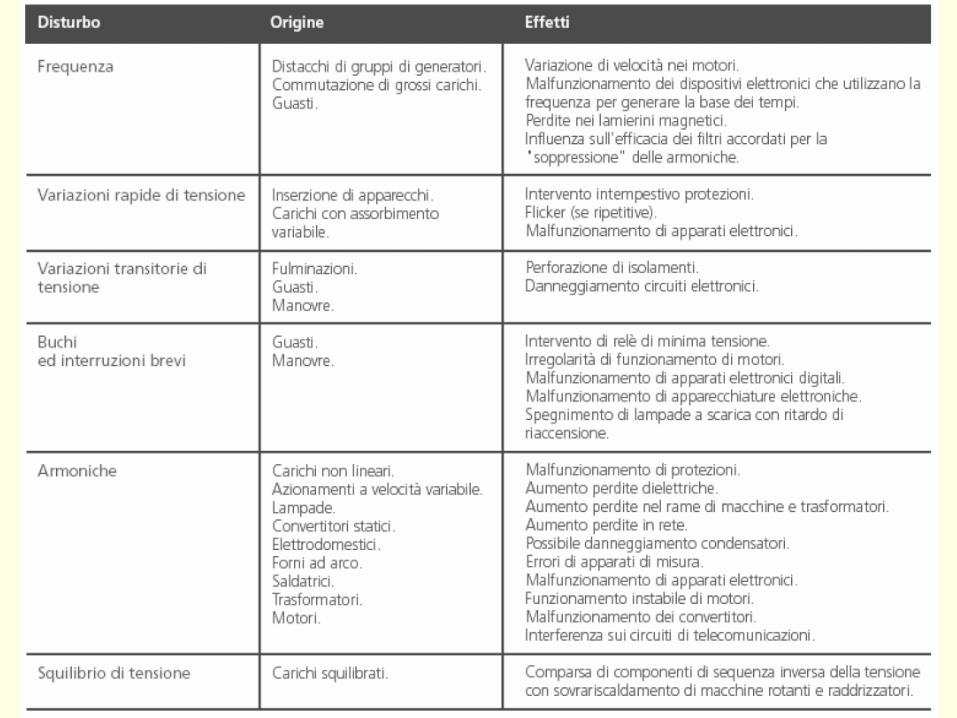
16
17
Universitagrave degli Studi di Cassino e del Lazio Meridionale
La Qualitagrave dellrsquoEnergia Elettrica (Power Quality ndash PQ)
CURVA DI TOLLERANZA AI DISTURBI
18
Caratteristiche dellrsquoalimentazione a bassa tensione
Universitagrave degli Studi di Cassino e del Lazio Meridionale
La Qualitagrave dellrsquoEnergia Elettrica (Power Quality ndash PQ)
19
Caratteristiche dellrsquoalimentazione a bassa tensione
Frequenza nominale
La frequenza nominale della tensione fornita deve essere di 50 Hz In condizioni normali
di esercizio il valore medio misurato nellrsquointervallo di 10 secondi deve essere
Per i sistemi con collegamento sincrono ad un sistema interconnesso
1 50 Hz plusmn 1 durante il 95 di un anno
2 50 Hz +4 - 6 durante il 100 di un anno
Per i sistemi senza collegamento sincrono ad un sistema interconnesso
1 50 Hz plusmn 2 durante il 95 di un anno
2 50 Hz plusmn 15 durante il 100 di un anno
Universitagrave degli Studi di Cassino e del Lazio Meridionale
La Qualitagrave dellrsquoEnergia Elettrica (Power Quality ndash PQ)
20
Caratteristiche dellrsquoalimentazione a bassa tensione
Universitagrave degli Studi di Cassino e del Lazio Meridionale
La Qualitagrave dellrsquoEnergia Elettrica (Power Quality ndash PQ)
21
Caratteristiche dellrsquoalimentazione a bassa tensione
Universitagrave degli Studi di Cassino e del Lazio Meridionale
La Qualitagrave dellrsquoEnergia Elettrica (Power Quality ndash PQ)
22
Variazioni della tensione di alimentazione (variazioni lente)
Le variazioni lente sono deviazioni ldquomedierdquo dal valore nominale dellrsquoampiezza della
tensione di consegna entro una fascia predefinita (per esempio del plusmn10) rispetto alla
tensione dichiarata
CAUSE variazione lenta dei carichi e dalla corrispondente azione di regolazione effettuata dai
variatori sotto carico dei trasformatori
Universitagrave degli Studi di Cassino e del Lazio Meridionale
La Qualitagrave dellrsquoEnergia Elettrica (Power Quality ndash PQ)
23
Variazioni della tensione di alimentazione (variazioni rapide)
Le variazioni rapide sono abbassamenti (o aumenti) bruschi di qualche percento della
tensione preesistente generalmente seguiti se abbassamenti da un ritorno (a rampa o di
altra forma) ad un valore intermedio tra quello preesistente e tra il minimo raggiunto
CAUSE commutazione dei carichi (partenza motori in particolare) funzionamento di carichi
con ciclo operativo particolarmente variabile e in qualche caso da manovre in rete (linee
trasformatori condensatori ecc)
Universitagrave degli Studi di Cassino e del Lazio Meridionale
La Qualitagrave dellrsquoEnergia Elettrica (Power Quality ndash PQ)
24
Flicker Il flicker egrave originato dalla fluttuazione della tensione Si definisce fluttuazione di tensione una
serie di variazioni rapide (uguali o diverse) della tensione
Fluttuazioni di tensione che presentano frequenze di modulazione del 50 Hz comprese tra 05 e
40 Hz danno origine al fenomeno del flicker (sfarfallio) ovvero della sensazione visiva
provocata dalle fluttuazioni dellrsquointensitagrave di illuminazione delle lampade
I suoi principali effetti sullrsquouomo possono essere mal di testa irritabilitagrave e fastidio agli occhi
Universitagrave degli Studi di Cassino e del Lazio Meridionale
La Qualitagrave dellrsquoEnergia Elettrica (Power Quality ndash PQ)
25
Universitagrave degli Studi di Cassino e del Lazio Meridionale
La Qualitagrave dellrsquoEnergia Elettrica (Power Quality ndash PQ)
26
La Qualitagrave dellrsquoEnergia Elettrica (Power Quality ndash PQ)
Universitagrave degli Studi di Cassino e del Lazio Meridionale
La Qualitagrave dellrsquoEnergia Elettrica (Power Quality ndash PQ)
27
Universitagrave degli Studi di Cassino e del Lazio Meridionale
La Qualitagrave dellrsquoEnergia Elettrica (Power Quality ndash PQ)
28
Universitagrave degli Studi di Cassino e del Lazio Meridionale
La Qualitagrave dellrsquoEnergia Elettrica (Power Quality ndash PQ)
29
Universitagrave degli Studi di Cassino e del Lazio Meridionale
La Qualitagrave dellrsquoEnergia Elettrica (Power Quality ndash PQ)
30
Universitagrave degli Studi di Cassino e del Lazio Meridionale
La Qualitagrave dellrsquoEnergia Elettrica (Power Quality ndash PQ)
31
Universitagrave degli Studi di Cassino e del Lazio Meridionale
La Qualitagrave dellrsquoEnergia Elettrica (Power Quality ndash PQ)
32
Buchi di tensione Riduzione temporanea della tensione in un punto della rete elettrica sotto una determinata
soglia Se durante un buco la tensione scende sotto una soglia di interruzione lrsquoevento egrave
considerato essere sia un buco che unrsquointerruzione
CAUSE I buchi di tensione sono generalmente dovuti a guasti che sopravvengono negli
impianti utilizzatori o nel sistema di distribuzione pubblico Possono dipendere anche variazioni
di carico lungo la linea
Universitagrave degli Studi di Cassino e del Lazio Meridionale
La Qualitagrave dellrsquoEnergia Elettrica (Power Quality ndash PQ)
33
Interruzioni della tensione di alimentazione Condizione in cui la tensione ad un terminale della rete egrave inferiore allrsquo1 della tensione
nominale per una durata fino a tre minuti (brevi) o maggiori di 3 minuti (lunghe)
Universitagrave degli Studi di Cassino e del Lazio Meridionale
La Qualitagrave dellrsquoEnergia Elettrica (Power Quality ndash PQ)
34
Sovratensioni temporanee alla frequenza di rete fra fasi e terra Le sovratensioni sono sopraelevazioni della tensione conseguenti a modificazioni dello
stato elettrico della rete elettrica
Universitagrave degli Studi di Cassino e del Lazio Meridionale
La Qualitagrave dellrsquoEnergia Elettrica (Power Quality ndash PQ)
35
Armoniche Le armoniche sono tensioni o correnti sinusoidali con frequenza pari ad un multiplo intero
(ordine) della frequenza fondamentale di funzionamento del sistema elettrico la cui
presenza determina una distorsione della forma drsquoonda della tensione di alimentazione
CAUSE In piccola parte dal sistema stesso (trasformatori etc) e per la maggior parte da
apparecchi utilizzatori carichi commutati elettronicamente raddrizzatori convertitori regolatori
in AC cicloconvertitori ecc carichi con caratteristiche non lineari apparecchiature a
saturazione magnetica lampade a scarica forni ad arco saldatrici ad arco trasformatori ecc
bull carichi inseriti e disinseriti da organi di manovra condensatori filtri e motori a induzione
Universitagrave degli Studi di Cassino e del Lazio Meridionale
La Qualitagrave dellrsquoEnergia Elettrica (Power Quality ndash PQ)
36
Armoniche di tensione e corrente ndash Problemi
Vi sono diversi ambiti causati dalle armoniche
bull problemi causati da armoniche di corrente
1048707 sovraccarico del neutro
1048707 aumento delle perdite nei trasformatori
1048707 interventi intempestivi degli interruttori automatici
1048707 aumento dellrsquoeffetto pelle
bull problemi causati da armoniche di tensione
1048707 deformazione della tensione
1048707 disturbi nella coppia dei motori ad induzione
1048707 rumore al passaggio per lo zero
bull problemi causati quando le armoniche di corrente raggiungono lrsquoalimentazione
Universitagrave degli Studi di Cassino e del Lazio Meridionale
La Qualitagrave dellrsquoEnergia Elettrica (Power Quality ndash PQ)
37
38
Universitagrave degli Studi di Cassino e del Lazio Meridionale
La Qualitagrave dellrsquoEnergia Elettrica (Power Quality ndash PQ)
39
Strumentazione ldquohand heldrdquo con display
Universitagrave degli Studi di Cassino e del Lazio Meridionale
La Qualitagrave dellrsquoEnergia Elettrica (Power Quality ndash PQ)
40
Strumentazione ldquohand heldrdquo con display
Universitagrave degli Studi di Cassino e del Lazio Meridionale
La Qualitagrave dellrsquoEnergia Elettrica (Power Quality ndash PQ)
41
Strumentazione da registrazione
Universitagrave degli Studi di Cassino e del Lazio Meridionale
La Qualitagrave dellrsquoEnergia Elettrica (Power Quality ndash PQ)
42
Schema di principio ndash 61000-4-30 copy IEC2008
The electrical quantity to be measured may be either directly accessible as is
generally the case in low-voltage systems or accessible via measurement
transducers
An instrument may include the whole measurement chain In this standard the
normative part does not consider the measurement transducers external to the
instrument and their associated uncertainty
Universitagrave degli Studi di Cassino e del Lazio Meridionale
La Qualitagrave dellrsquoEnergia Elettrica (Power Quality ndash PQ)
43
Universitagrave degli Studi di Cassino Corso di Fondamenti di Misure
La Qualitagrave dellrsquoEnergia Elettrica (Power Quality ndash PQ)
Classi dei metodi di misura - 61000-4-30 copy IEC2008
For each class measurement methods and appropriate performance requirements
are included
Sono definite tre classi A S e B
Class A
This class is used where precise measurements are necessary for example for contractual
applications that may require resolving disputes verifying compliance with standards etc
Any measurements of a parameter carried out with two different instruments complying with
the requirements of Class A when measuring the same signals will produce matching results
within the specified uncertainty for that parameter
Class S
This class is used for statistical applications such as surveys or power quality assessment
possibly with a limited subset of parameters Although it uses equivalent intervals of
measurement as class A the class S processing requirements are lower
Class B
This class is defined in order to avoid making many existing instruments designs obsolete
NOTE Class B methods are not recommended for new designs Readers are advised that Class B may be removed in a
future Edition of this standard
44
Classi dei metodi di misura - 61000-4-30 copy IEC2008
Measurement aggregation over time intervals
CLASS A
The basic measurement time interval for parameter magnitudes (supply voltage harmonics
interharmonics and unbalance) shall be a 10-cycle time interval for a 50 Hz power system
or 12-cycle time interval for a 60 Hz power system
The 1012-cycle measurement shall be re-synchronized at every RTC 10 min tick
The 1012-cycle values are then aggregated over 3 additional intervals
ndash 150180-cycle interval (150 cycles for 50 Hz nominal or 180 cycles for 60 Hz nominal)
ndash 10 min interval
ndash 2 h interval
CLASS S
Same time intervals as Class A
CLASS B
The manufacturer shall specify the number and duration of aggregation time intervals
Universitagrave degli Studi di Cassino e del Lazio Meridionale
La Qualitagrave dellrsquoEnergia Elettrica (Power Quality ndash PQ)
45
Universitagrave degli Studi di Cassino e del Lazio Meridionale
La Qualitagrave dellrsquoEnergia Elettrica (Power Quality ndash PQ)
46
Universitagrave degli Studi di Cassino e del Lazio Meridionale
La Qualitagrave dellrsquoEnergia Elettrica (Power Quality ndash PQ)
Class A
The 10-min aggregated value shall be tagged with the absolute time (for
example 01H1000) The time tag is the time at the conclusion of the 10-min
aggregation
The data for the 10-min time interval shall be aggregated from 1012-cycle time
intervals
Each 10-minute interval shall begin on a UTC 10-min tick The 10-min tick is
also used to re-synchronize the 1012-cycle intervals and the 150180-cycle
intervals
The final 1012-cycle interval(s) in a 10-min aggregation period will typically
overlap in time with the UTC 10-min clock tick Any overlapping 1012-cycle
interval (Overlap 1 in Figure 2) is included in the aggregation of the previous
10-min interval
47
Universitagrave degli Studi di Cassino e del Lazio Meridionale
La Qualitagrave dellrsquoEnergia Elettrica (Power Quality ndash PQ)
48
Universitagrave degli Studi di Cassino e del Lazio Meridionale
La Qualitagrave dellrsquoEnergia Elettrica (Power Quality ndash PQ)
49
Classi dei metodi di misura - 61000-4-30 copy IEC2008
Real time clock (RTC) uncertainty
Sono definite le specifiche per le 3 classi
Flagging concept
During a dip swell or interruption the measurement algorithm for other
parameters (for example frequency measurement) might produce an unreliable
value The flagging concept therefore avoids counting a single event more than
once in different parameters (for example counting a single dip as both a dip and a
frequency variation) and indicates that an aggregated value might be unreliable
Universitagrave degli Studi di Cassino e del Lazio Meridionale
La Qualitagrave dellrsquoEnergia Elettrica (Power Quality ndash PQ)
50
Classi dei metodi di misura - 61000-4-30 copy IEC2008
Power quality parameters - INDICES
Per ogni parametro viene suggerito il metodo di misura per le tre classi e
(soprattutto) le caratteristiche di precisione Per alcuni parametri rimanda a
specifiche norme (ad esempio Flicker e Armonicheinterarmoniche)
Esempio - Power frequency Class A
The frequency reading shall be obtained every 10 s As power frequency may not be exactly 50 Hz or 60
Hz within the 10 s time clock interval the number of cycles may not be an integer number The
fundamental frequency output is the ratio of the number of integral cycles counted during the 10 s time
clock interval divided by the cumulative duration of the integer cycles Before each assessment
harmonics and interharmonics shall be attenuated to minimize the effects of multiple zero crossings
The measurement time intervals shall be non-overlapping Individual cycles that overlap the 10 s time
clock are discarded Each 10 s interval shall begin on an absolute 10 s time clock with uncertainty as
defined in 46
Other techniques that provide equivalent results such as convolution are acceptable
Class S Same as class A
Class B The manufacturer shall specify the process used for frequency measurement
Universitagrave degli Studi di Cassino e del Lazio Meridionale
La Qualitagrave dellrsquoEnergia Elettrica (Power Quality ndash PQ)
51
Classi dei metodi di misura - 61000-4-30 copy IEC2008
Power quality parameters - INDICES
Per ogni parametro viene suggerito il metodo di misura per le tre classi e
(soprattutto) le caratteristiche di precisione Per alcuni parametri rimanda a
specifiche norme (ad esempio Flicker e Armonicheinterarmoniche)
Esempio - Power frequency
Measurement uncertainty and measuring range
ndash Class A
Under the conditions described in 61 the measurement uncertainty shall not exceed
plusmn10 mHz over the measuring ranges 425 Hz ~ 575 Hz 51 Hz ~ 69 Hz
ndash Class S
Under the conditions described in 61 the measurement uncertainty shall not exceed
plusmn50 mHz over the measuring ranges 425 Hz ~ 575 Hz 51 Hz ~ 69 Hz
ndash Class B
The manufacturer shall specify the uncertainty over the measuring ranges 425 Hz ~
575 Hz 51 Hz ~ 69 Hz
Universitagrave degli Studi di Cassino e del Lazio Meridionale
La Qualitagrave dellrsquoEnergia Elettrica (Power Quality ndash PQ)
52
Magnitude of the supply voltage
Measurement method
ndash Class A
The measurement shall be the rms value of the voltage magnitude over
a 10-cycle time interval for 50 Hz power system or 12-cycle time
interval for 60 Hz power system Every 1012-cycle interval shall be
contiguous and not overlapping with adjacent 1012-cycle intervals
except as shown as Overlap 1 in Figure 2
NOTE 1 This specific measurement method is used for quasi-stationary signals and is
not used for the detection and measurement of disturbances dips swells voltage
interruptions and transients
NOTE 2 The rms value includes by definition harmonics interharmonics mains
signalling etc
- Class S same as Class A
Universitagrave degli Studi di Cassino e del Lazio Meridionale
La Qualitagrave dellrsquoEnergia Elettrica (Power Quality ndash PQ)
53
Magnitude of the supply voltage
Measurement uncertainty and measuring range
ndash Class A
Under the conditions described in Clause 6 the measurement uncertainty
shall not exceed plusmn01 of Udin over the range of 10 ~ 150 of Udin
ndash Class S
Under the conditions described in Clause 6 the measurement uncertainty
shall not exceed plusmn05 of Udin over the range of 20 ~ 120 of Udin
Universitagrave degli Studi di Cassino e del Lazio Meridionale
La Qualitagrave dellrsquoEnergia Elettrica (Power Quality ndash PQ)
54
Supply voltage dips and swells
Measurement method
ndash Class A
The basic measurement Urms of a voltage dip and swell shall be the
Urms(frac12) on each measurement channel (see Clause 322)
The cycle duration for Urms(frac12) depends on the frequency The
frequency might be determined by the last non-flagged power frequency
measurement (see Clause 47 and Clause 51) or by any other method
that yields the uncertainty requirements of Clause 6
NOTE 1 The Urms(frac12) value includes by definition harmonics interharmonics mains
signalling voltage etc
NOTE 2 It is important to avoid loss of data when dips and swells occur in a rapid
sequence (for example three events in one second with up to one minute between
sequences may occur when a recloser operates into a sustained fault) If during a rapid
burst the dipswell event characteristics cannot be recorded then a count of events may
be useful
Universitagrave degli Studi di Cassino e del Lazio Meridionale
La Qualitagrave dellrsquoEnergia Elettrica (Power Quality ndash PQ)
55
Supply voltage dips and swells
Detection and evaluation of a voltage dip
Voltage dip detection
The dip threshold is a percentage of either Udin or the sliding voltage
reference Usr (see 525 544) The user shall declare the reference
voltage in use
NOTE ndash On single-phase systems a voltage dip begins when the Urms voltage falls
below the dip threshold and ends when the Urms voltage is equal to or above the dip
threshold plus the hysteresis voltage
ndash On polyphase systems a dip begins when the Urms voltage of one or more channels is
below the dip threshold and ends when the Urms voltage on all measured channels is
equal to or above the dip threshold plus the hysteresis voltage
The dip threshold and the hysteresis voltage are both set by the user according to the
use
Universitagrave degli Studi di Cassino e del Lazio Meridionale
La Qualitagrave dellrsquoEnergia Elettrica (Power Quality ndash PQ)
56
Calculation of a sliding reference voltage
The sliding reference voltage implementation is optional not mandatory
If a sliding reference is chosen for voltage dip or swell detection this
shall be calculated using a first-order filter with a 1-min time constant
This filter is given by
Usr(n) = 09967 times Usr(nndash1) + 00033 times U(1012)rms
where
Usr(n) is the present value of the sliding reference voltage
Usr(nndash1) is the previous value of the sliding reference voltage and
U(1012)rms is the most recent 1012-cycle rms value
When the measurement is started the initial value of the sliding reference voltage is set
to the declared input voltage The sliding reference voltage is updated every 1012-
cycles If a 1012-cycle value is flagged the sliding reference voltage is not updated
and the previous value is used
Universitagrave degli Studi di Cassino e del Lazio Meridionale
La Qualitagrave dellrsquoEnergia Elettrica (Power Quality ndash PQ)
57
Supply voltage dips and swells
Voltage dip evaluation
A voltage dip is characterized by a pair of data either residual voltage
(Ures) or depth and duration
ndash the residual voltage of a voltage dip is the lowest Urms(frac12) value
measured on any channel during the dip
ndash the depth is the difference between the reference voltage (either Udin
or Usr) and the residual voltage It is generally expressed in percentage
of the reference voltage
NOTE 1 During the dip it may be useful to also record the lowest Urms(frac12) on each
channel in addition to the residual voltage of the dip The duration spent below the dip
threshold on each channel may also be useful
Universitagrave degli Studi di Cassino e del Lazio Meridionale
La Qualitagrave dellrsquoEnergia Elettrica (Power Quality ndash PQ)
58
Supply voltage dips and swells
Voltage dip evaluation
NOTE 2 If voltage waveforms are recorded before during and after a
dip useful information about phase angle changes may be available in
the recorded data
The start time of a dip shall be time stamped with the time of the start of
the Urms of the channel that initiated the event and the end time of the
dip shall be the time stamped with the time of the end of the Urms that
ended the event as defined by the threshold plus the hysteresis
The duration of a voltage dip is the time difference between the start
time and the end time of the voltage dip
Universitagrave degli Studi di Cassino e del Lazio Meridionale
La Qualitagrave dellrsquoEnergia Elettrica (Power Quality ndash PQ)
59
Supply voltage dips and swells
Residual voltage and swell voltage magnitude measurement
uncertainty
ndash Class A
The measurement uncertainty shall not exceed plusmn02 of Udin
ndash Class S
The measurement uncertainty shall not exceed plusmn10 of Udin
Universitagrave degli Studi di Cassino e del Lazio Meridionale
La Qualitagrave dellrsquoEnergia Elettrica (Power Quality ndash PQ)
60
Schema di principio ndash 61000-4-7 copy IEC2002
Universitagrave degli Studi di Cassino e del Lazio Meridionale
La Qualitagrave dellrsquoEnergia Elettrica (Power Quality ndash PQ)
61
Universitagrave degli Studi di Cassino e del Lazio Meridionale
La Qualitagrave dellrsquoEnergia Elettrica (Power Quality ndash PQ)
62
Universitagrave degli Studi di Cassino e del Lazio Meridionale
La Qualitagrave dellrsquoEnergia Elettrica (Power Quality ndash PQ)
63
Inter-Armoniche Le inter-armoniche sono tensioni o correnti sinusoidali con frequenza diversa da un
multiplo intero della fondamentale la cui presenza determina una distorsione
(modulazione) della forma donda della tensione di alimentazione
CAUSE dai carichi che assorbono correnti inter-armoniche
- carichi commutati elettronicamente convertitori cascata subsincrona cicloconvertitori regolatori con
controllo a pacchetti di cicli ecc
- carichi con caratteristiche non lineari eo non stazionarie forni ad arco saldatrici ad arco ecc
Universitagrave degli Studi di Cassino e del Lazio Meridionale
La Qualitagrave dellrsquoEnergia Elettrica (Power Quality ndash PQ)
64
Universitagrave degli Studi di Cassino e del Lazio Meridionale
La Qualitagrave dellrsquoEnergia Elettrica (Power Quality ndash PQ)
Un porsquo di esempi e
consigli praticihellip
65
0V
50V
100V
150V
200V
250V
300V
350V
0ms 5ms 10ms 15ms 20ms
t
u
0A
1A
2A
3A
i
0V
50V
100V
150V
200V
250V
300V
350V
0ms 5ms 10ms 15ms 20ms
t
u
0A
1A
2A
3A
i
0V
50V
100V
150V
200V
250V
300V
350V
0ms 5ms 10ms 15ms 20ms
t
u
0A
1A
2A
3A
i
gleichgerichtete
Netzspannung
Kondensator-
spannung
gleichgerichteter
Netzstrom
The situation
today
bull Computed current and voltage profiles when a
230 V 58 W fluorescent lamp with an old-style
electronic ballast is driven on the phase wire of
a typical power distribution system
System voltage 230 V
System frequency 50 Hz
Source resistance 500 mW
Longitudinal induction 904 microH
System impedance 575 mW
Mean dc current 180 mA
Smoothing capacitance220 microF
66
And what about electronic ballasts that are rated over 25W
Introduce electronic power factor correction (PFC)
0V
20V
40V
60V
80V
100V
120V
140V
160V
180V
200V
220V
0deg 15deg 30deg 45deg
u
00A
03A
06A
09A
12A
i
67
Though todayrsquos ballasts are better if
rated gt25 W bull Only
the
small
ones
continu
e to
pollute
just like
PCs
TV sets
do
68
This leads to a number of
previously unknown effects bull 1 Deformed voltage curves
bull 2 Huge inrush current peaks
bull 3 Instrument dependent measured parameters
bull 4 Increased loading of phase conductors
bull 5 Loading and overloading of the neutral conductor
bull 6 Overheating and start-up problems of induction motors
bull 7 Additional stray losses in transformers
bull 8 Repercussions of generators upon the mains
bull 9 Influence of capacitors repercussions upon the mains
and four additional complications in TN-C systems
10 Stray currents in equipotential bonding system magnetic fields
11 Contamination of data streams by stray currents
12 Stray currents in the earthing system corrosion damage
13 Lightning currents in devices and equipment
69
1 Deformed voltage curves
bull in theory
-350V
-300V
-250V
-200V
-150V
-100V
-50V
0V
50V
100V
150V
200V
250V
300V
350V
0 5 10 15 20
t ms
u
System voltage profile when driving
a single-phase load comprising
twenty 58 W energy-saver lamps in
parallel on a typical 230 V power
system
70
and in practice
bull An actual
current profile
bull
bull and
bull a voltage profile
bull
bull recorded in a large storage
dispatch and administrative
building
71
at home or in industrial environments
bull
bull Television 40
W
bull 200 Vdiv 2
Adiv
bull 5 msdiv
Harmonic
spectrum
Frequency
converter
50 Adiv
Phase currents
I1=I2=I3=160 A
IN=295 A
5 msdiv
72
Every periodic waveform can be written
as the infinite sum of sinusoidal waves
-175
-150
-125
-100
-75
-50
-25
0
25
50
75
100
125
150
175
0 5 10 15 20
t ms
i
mA
itot
i1
Synthesis of a triangular current profile 100mA
Content fundamental I = 99 mA Isup2 = 9855 mAsup2
Sum of squares Isup2 = 9855 mAsup2
Root of sum = RMS value I = 99 mA
-175
-150
-125
-100
-75
-50
-25
0
25
50
75
100
125
150
175
0 5 10 15 20
t ms
i
mA
itot
i1
i3
Synthesis of a triangular current profile 100mA
Content fundamental I = 99 mA Isup2 = 9855 mAsup2
Cont 3 rd harmonic I = -11 mA Isup2 = 122 mAsup2
Sum of squares Isup2 = 9977 mAsup2
Root of sum = RMS value I = 100 mA
-175
-150
-125
-100
-75
-50
-25
0
25
50
75
100
125
150
175
0 5 10 15 20
t ms
i
mA
itot
i1
i3
i5
Synthesis of a triangular current profile 100mA
Content fundamental I = 99 mA Isup2 = 9855 mAsup2
Cont 3 rd harmonic I = -11 mA Isup2 = 122 mAsup2
Cont 5 th harmonic I = 4 mA Isup2 = 16 mAsup2
Sum of squares Isup2 = 9993 mAsup2
Root of sum = RMS value I = 100 mA
-175
-150
-125
-100
-75
-50
-25
0
25
50
75
100
125
150
175
0 5 10 15 20
t ms
i
mA
itot
i1
i3
i5
i7
Synthesis of a triangular current profile 100mA
Content fundamental I = 99 mA Isup2 = 9855 mAsup2
Cont 3 rd harmonic I = -11 mA Isup2 = 122 mAsup2
Cont 5 th harmonic I = 4 mA Isup2 = 16 mAsup2
Cont 7 th harmonic I = -2 mA Isup2 = 4 mAsup2
Sum of squares Isup2 = 9997 mAsup2
Root of sum = RMS value I = 100 mA
-175
-150
-125
-100
-75
-50
-25
0
25
50
75
100
125
150
175
0 5 10 15 20
t ms
i
mA
itot i1
i3 i5
i7 i9
Synthesis of a triangular current profile 100mA
Content fundamental I = 99 mA Isup2 = 9855 mAsup2
Cont 3 rd harmonic I = -11 mA Isup2 = 122 mAsup2
Cont 5 th harmonic I = 4 mA Isup2 = 16 mAsup2
Cont 7 th harmonic I = -2 mA Isup2 = 4 mAsup2
Cont 9 th harmonic I = 1 mA Isup2 = 2 mAsup2
Sum of squares Isup2 = 9998 mAsup2
Root of sum = RMS value I = 100 mA
-175
-150
-125
-100
-75
-50
-25
0
25
50
75
100
125
150
175
0 5 10 15 20
t ms
i
mA
itot i1
i3 i5
i7 i9
i11
Synthesis of a triangular current profile 100mA
Content fundamental I = 99 mA Isup2 = 9855 mAsup2
Cont 3 rd harmonic I = -11 mA Isup2 = 122 mAsup2
Cont 5 th harmonic I = 4 mA Isup2 = 16 mAsup2
Cont 7 th harmonic I = -2 mA Isup2 = 4 mAsup2
Cont 9 th harmonic I = 1 mA Isup2 = 2 mAsup2
Cont 11 th harmonic I = -1 mA Isup2 = 1 mAsup2
Sum of squares Isup2 = 9999 mAsup2
Root of sum = RMS value I = 100 mA
-175
-150
-125
-100
-75
-50
-25
0
25
50
75
100
125
150
175
0 5 10 15 20
t ms
i
mA
itot i1
i3 i5
i7 i9
i11 i13
Synthesis of a triangular current profile 100mA
Content fundamental I = 99 mA Isup2 = 9855 mAsup2
Cont 3 rd harmonic I = -11 mA Isup2 = 122 mAsup2
Cont 5 th harmonic I = 4 mA Isup2 = 16 mAsup2
Cont 7 th harmonic I = -2 mA Isup2 = 4 mAsup2
Cont 9 th harmonic I = 1 mA Isup2 = 2 mAsup2
Cont 11 th harmonic I = -1 mA Isup2 = 1 mAsup2
Cont 13 th harmonic I = 1 mA Isup2 = 0 mAsup2
Sum of squares Isup2 = 9999 mAsup2
Root of sum = RMS value I = 100 mA
-175
-150
-125
-100
-75
-50
-25
0
25
50
75
100
125
150
175
0 5 10 15 20
t ms
i
mA
itot i1
i3 i5
i7 i9
i11 i13
i15
Synthesis of a triangular current profile 100mA
Content fundamental I = 99 mA Isup2 = 9855 mAsup2
Cont 3 rd harmonic I = -11 mA Isup2 = 122 mAsup2
Cont 5 th harmonic I = 4 mA Isup2 = 16 mAsup2
Cont 7 th harmonic I = -2 mA Isup2 = 4 mAsup2
Cont 9 th harmonic I = 1 mA Isup2 = 2 mAsup2
Cont 11 th harmonic I = -1 mA Isup2 = 1 mAsup2
Cont 13 th harmonic I = 1 mA Isup2 = 0 mAsup2
Cont 15 th harmonic I = 0 mA Isup2 = 0 mAsup2
Sum of squares Isup2 = 10000 mAsup2
Root of sum = RMS value I = 100 mA
-175
-150
-125
-100
-75
-50
-25
0
25
50
75
100
125
150
175
0 5 10 15 20
t ms
i
mA
itot i1
i3 i5
i7 i9
i11 i13
i15 i17
Synthesis of a triangular current profile 100mA
Content fundamental I = 99 mA Isup2 = 9855 mAsup2
Cont 3 rd harmonic I = -11 mA Isup2 = 122 mAsup2
Cont 5 th harmonic I = 4 mA Isup2 = 16 mAsup2
Cont 7 th harmonic I = -2 mA Isup2 = 4 mAsup2
Cont 9 th harmonic I = 1 mA Isup2 = 2 mAsup2
Cont 11 th harmonic I = -1 mA Isup2 = 1 mAsup2
Cont 13 th harmonic I = 1 mA Isup2 = 0 mAsup2
Cont 15 th harmonic I = 0 mA Isup2 = 0 mAsup2
Cont 17 th harmonic I = 0 mA Isup2 = 0 mAsup2
Sum of squares Isup2 = 10000 mAsup2
Root of sum = RMS value I = 100 mA
73
whose frequencies called harmonics are
integer multiples of the fundamental frequency
-175
-150
-125
-100
-75
-50
-25
0
25
50
75
100
125
150
175
0 5 10 15 20
t ms
i
mA
itot
i1
Synthesis of a rectangular current profile 100mA
Content fundamental I = 90 mA Isup2 = 8106 mAsup2
Sum of squares Isup2 = 8106 mAsup2
Root of sum = RMS value I = 90 mA
-175
-150
-125
-100
-75
-50
-25
0
25
50
75
100
125
150
175
0 5 10 15 20
t ms
i
mA
itot
i1
i3
Synthesis of a rectangular current profile 100mA
Content fundamental I = 90 mA Isup2 = 8106 mAsup2
Cont 3 rd harmonic I = 30 mA Isup2 = 901 mAsup2
Sum of squares Isup2 = 9006 mAsup2
Root of sum = RMS value I = 95 mA
-175
-150
-125
-100
-75
-50
-25
0
25
50
75
100
125
150
175
0 5 10 15 20
t ms
i
mA
itot
i1
i3
i5
Synthesis of a rectangular current profile 100mA
Content fundamental I = 90 mA Isup2 = 8106 mAsup2
Cont 3 rd harmonic I = 30 mA Isup2 = 901 mAsup2
Cont 5 th harmonic I = 18 mA Isup2 = 324 mAsup2
Sum of squares Isup2 = 9331 mAsup2
Root of sum = RMS value I = 97 mA
-175
-150
-125
-100
-75
-50
-25
0
25
50
75
100
125
150
175
0 5 10 15 20
t ms
i
mA
itot
i1
i3
i5
i7
Synthesis of a rectangular current profile 100mA
Content fundamental I = 90 mA Isup2 = 8106 mAsup2
Cont 3 rd harmonic I = 30 mA Isup2 = 901 mAsup2
Cont 5 th harmonic I = 18 mA Isup2 = 324 mAsup2
Cont 7 th harmonic I = 13 mA Isup2 = 165 mAsup2
Sum of squares Isup2 = 9496 mAsup2
Root of sum = RMS value I = 97 mA
-175
-150
-125
-100
-75
-50
-25
0
25
50
75
100
125
150
175
0 5 10 15 20
t ms
i
mA
itot i1
i3 i5
i7 i9
Synthesis of a rectangular current profile 100mA
Content fundamental I = 90 mA Isup2 = 8106 mAsup2
Cont 3 rd harmonic I = 30 mA Isup2 = 901 mAsup2
Cont 5 th harmonic I = 18 mA Isup2 = 324 mAsup2
Cont 7 th harmonic I = 13 mA Isup2 = 165 mAsup2
Cont 9 th harmonic I = 10 mA Isup2 = 100 mAsup2
Sum of squares Isup2 = 9596 mAsup2
Root of sum = RMS value I = 98 mA
-175
-150
-125
-100
-75
-50
-25
0
25
50
75
100
125
150
175
0 5 10 15 20
t ms
i
mA
itot i1
i3 i5
i7 i9
i11
Synthesis of a rectangular current profile 100mA
Content fundamental I = 90 mA Isup2 = 8106 mAsup2
Cont 3 rd harmonic I = 30 mA Isup2 = 901 mAsup2
Cont 5 th harmonic I = 18 mA Isup2 = 324 mAsup2
Cont 7 th harmonic I = 13 mA Isup2 = 165 mAsup2
Cont 9 th harmonic I = 10 mA Isup2 = 100 mAsup2
Cont 11 th harmonic I = 8 mA Isup2 = 67 mAsup2
Sum of squares Isup2 = 9663 mAsup2
Root of sum = RMS value I = 98 mA
-175
-150
-125
-100
-75
-50
-25
0
25
50
75
100
125
150
175
0 5 10 15 20
t ms
i
mA
itot i1
i3 i5
i7 i9
i11 i13
Synthesis of a rectangular current profile 100mA
Content fundamental I = 90 mA Isup2 = 8106 mAsup2
Cont 3 rd harmonic I = 30 mA Isup2 = 901 mAsup2
Cont 5 th harmonic I = 18 mA Isup2 = 324 mAsup2
Cont 7 th harmonic I = 13 mA Isup2 = 165 mAsup2
Cont 9 th harmonic I = 10 mA Isup2 = 100 mAsup2
Cont 11 th harmonic I = 8 mA Isup2 = 67 mAsup2
Cont 13 th harmonic I = 7 mA Isup2 = 48 mAsup2
Sum of squares Isup2 = 9711 mAsup2
Root of sum = RMS value I = 99 mA
-175
-150
-125
-100
-75
-50
-25
0
25
50
75
100
125
150
175
0 5 10 15 20
t ms
i
mA
itot i1
i3 i5
i7 i9
i11 i13
i15
Synthesis of a rectangular current profile 100mA
Content fundamental I = 90 mA Isup2 = 8106 mAsup2
Cont 3 rd harmonic I = 30 mA Isup2 = 901 mAsup2
Cont 5 th harmonic I = 18 mA Isup2 = 324 mAsup2
Cont 7 th harmonic I = 13 mA Isup2 = 165 mAsup2
Cont 9 th harmonic I = 10 mA Isup2 = 100 mAsup2
Cont 11 th harmonic I = 8 mA Isup2 = 67 mAsup2
Cont 13 th harmonic I = 7 mA Isup2 = 48 mAsup2
Cont 15 th harmonic I = 6 mA Isup2 = 36 mAsup2
Sum of squares Isup2 = 9747 mAsup2
Root of sum = RMS value I = 99 mA
-175
-150
-125
-100
-75
-50
-25
0
25
50
75
100
125
150
175
0 5 10 15 20
t ms
i
mA
itot i1
i3 i5
i7 i9
i11 i13
i15 i17
Synthesis of a rectangular current profile 100mA
Content fundamental I = 90 mA Isup2 = 8106 mAsup2
Cont 3 rd harmonic I = 30 mA Isup2 = 901 mAsup2
Cont 5 th harmonic I = 18 mA Isup2 = 324 mAsup2
Cont 7 th harmonic I = 13 mA Isup2 = 165 mAsup2
Cont 9 th harmonic I = 10 mA Isup2 = 100 mAsup2
Cont 11 th harmonic I = 8 mA Isup2 = 67 mAsup2
Cont 13 th harmonic I = 7 mA Isup2 = 48 mAsup2
Cont 15 th harmonic I = 6 mA Isup2 = 36 mAsup2
Cont 17 th harmonic I = 5 mA Isup2 = 28 mAsup2
Sum of squares Isup2 = 9775 mAsup2
Root of sum = RMS value I = 99 mA
74
Even far better simulations are
available free of charge at
bull wwwpowerstandardscomMcEachern
75
-4A
-3A
-2A
-1A
0A
1A
2A
3A
4A
0ms 5ms 10ms 15ms 20ms
t
i
-4A
-3A
-2A
-1A
0A
1A
2A
3A
4A
0ms 5ms 10ms 15ms 20ms
t
i
Applying the Fourier
analysis to a real PC
current does not work
directly
bull
bull but it can be
modelled by a similar
triangular curve in
which not all of the
higher harmonics
have been included
Triangular current profile of
the same amplitude and a
pulse duty cycle of 17
Input current of a PC
with monitor
76
Analysis of the model triangular waveform
-400
-350
-300
-250
-200
-150
-100
-50
0
50
100
150
200
250
300
350
400
0 5 10 15 20
t ms
iI
itot(t) L1 [A] i1(t) L1 [A]
i3(t) L1 [A] i5(t) L1 [A]
i7(t) L1 [A] i9(t) L1 [A]
i11(t) L1 [A] i13(t) L1 [A]
i15(t) L1 [A] i17(t) L1 [A]
77
M3
Harmonics
Energy
(active
power)
L1
L2
L3
N
PE
Important
bull Harmonics are created within the loads
themselves and can flow ldquoupstreamrdquo to
contaminate the power system
78
-6A
-5A
-4A
-3A
-2A
-1A
0A
1A
2A
3A
4A
5A
6A
0ms 5ms 10ms 15ms 20ms
t
i
Squared values
Without
Fundamental 502 mA 251986 mAsup2 the fundamental
3rd harmonic -479 mA 229000 mAsup2 229000 mAsup2
5th harmonic 434 mA 188595 mAsup2 188595 mAsup2
7th harmonic -374 mA 139903 mAsup2 139903 mAsup2
9th harmonic 304 mA 92527 mAsup2 92527 mAsup2
11th harmonic -232 mA 53671 mAsup2 53671 mAsup2
13th harmonic 163 mA 26600 mAsup2 26600 mAsup2
15th harmonic -104 mA 10780 mAsup2 10780 mAsup2
17th harmonic 57 mA 3299 mAsup2 3299 mAsup2
Sum of the squares 996362 mAsup2 744377 mAsup2
Root thereof 998 mAeff THD = 863 mA
What actually is THD Example shown here triangular current
profile with an rms current of 1000 mA
and a pulse duty cycle of 17
THDr (root mean square) = 863mA1000mA = 86
THDf (fundamental) = 863mA502mA = 172
79
Effect on phase-to-neutral
and phase-to-phase voltages
bull Recorded
on June
30 2002
230 p
m
bull What
was the
matter
then
bull The
soccer
final
Germany
vs
Brazil
80
The triple-N harmonics drive
a circulating current in the
delta winding of a distribution
transformer
bull but the
bull voltage harmonics
propagate into the next
low-voltage power
distribution system
81 0V
50V
100V
150V
200V
250V
300V
350V
400V
450V
500V
550V
0 10 20 30 40 50
t ms
u
0A
10A
20A
30A
40A
50A
60A
70A
80A
90A
100A
110A
120A
130A
140A
150A
i
Switching on just as supply voltage passes through zero
0V
50V
100V
150V
200V
250V
300V
350V
400V
450V
500V
550V
0 10 20 30 40 50
t ms
u
0A
10A
20A
30A
40A
50A
60A
70A
80A
90A
100A
110A
120A
130A
140A
150A
i
Switching on just as supply voltage is at its peak
2 Huge inrush current peaks
ndash in theory
82
and in practice
bull Inrush current of a
compact energy-
saver lamp and its
effect on the system
voltage (recorded at
the Technical
University of
Budapest)
bull
83
enables us to infer what
happens when run by a
normal three-phase supply
The same fluorescent lamp
with a magnetic ballast
bull The behaviour measured
when connected to
a dc supply
bull
Behaviour of a 58 W fluorescent lamp connected to a dc
supply
0
20
40
60
80
100
120
140
160
180
200
0 200 400 600 800 1000 1200
i mA
u
V
Measurement
Behaviour of a 58 W fluorescent lamp connected to a dc
supply
0
20
40
60
80
100
120
140
160
180
200
0 200 400 600 800 1000 1200
i mA
u
V
MeasurementCalculation
-350
-300
-250
-200
-150
-100
-50
0
50
100
150
200
250
300
350
0 5 10 15 20
t ms
u
V
-10
-08
-06
-04
-02
00
02
04
06
08
10
i
A
Systems voltage
Current
-350
-300
-250
-200
-150
-100
-50
0
50
100
150
200
250
300
350
0 5 10 15 20
t ms
u
V
-10
-08
-06
-04
-02
00
02
04
06
08
10
i
A
Systems voltage
Lamp voltage
Current
84
Warning ldquoCompensationrdquo is not
always what you think it is
bull Distinguish
between
bull Reactive
power
compensatio
n
aka power
factor
correction
Remedial
measure
Parallel (or
sometimes series)
compensation
using capacitors
Filter circuits
tuned to the
individual harmonic
frequencies
Harmonic
compensation
85
5 (Over)loading the neutral conductor
bull Magnetic ballast Old-style electronic ballast
-25A
-20A
-15A
-10A
-05A
00A
05A
10A
15A
20A
25A
0 5 10 15 20
t ms i
i(t) N
-25A
-20A
-15A
-10A
-05A
00A
05A
10A
15A
20A
25A
0 5 10 15 20
t ms
i
i(t) N
-25A
-20A
-15A
-10A
-05A
00A
05A
10A
15A
20A
25A
0 5 10 15 20
t ms
i
i(t) L1 i(t) L2 i(t) L3
-25A
-20A
-15A
-10A
-05A
00A
05A
10A
15A
20A
25A
0 5 10 15 20
t ms
i
i(t) L1
i(t) L2
i(t) L3
86
Adding the 3rd
harmonics
in the
neutral
wire
-150-100-50
050
100150
0deg 30deg 60deg 90deg 120deg 150deg 180deg 210deg 240deg 270deg 300deg 330deg 360deg
L1
-150-100-50
050
100150
0deg 30deg 60deg 90deg 120deg 150deg 180deg 210deg 240deg 270deg 300deg 330deg 360deg
L2
-150-100-50
050
100150
0deg 30deg 60deg 90deg 120deg 150deg 180deg 210deg 240deg 270deg 300deg 330deg 360deg
L3
-450-400-350-300-250-200-150-100-50
050
100150200250300350400450
0deg 30deg 60deg 90deg 120deg 150deg 180deg 210deg 240deg 270deg 300deg 330deg 360deg
f
iicirc
N
Physics dictates
that at any
moment in time
the phase and
neutral currents
must sum to zero
87
Effect on a three-phase ac motor
appears almost identical
bull The same motor is being
driven
simultaneously in
these three modes
homopolar system
zero-sequence system
direct system
positive-sequence system
inverse system
negative-sequence system
88
The transformer
influences the load
89
but the load also effects
the transformer
Total transformer loss is
2
)()(
nom
nomCunomFeLossI
IPPP
While total transformer loss really is
2
)(
2
)(
2
)(
nomnom
nomad
nom
nomCu
nom
nomFeLossI
I
f
fP
I
IP
U
UPP
90
6 ldquosupplementaryrdquo additional losses
in transformers
can be calculated rapidly
using the following two
simple formulae 50
2
2
1
2
11
Nn
n
nqh
I
In
I
I
e
eK
50
1
2
1
1
50
1
2
Nn
n
nNn
n
nI
IIII
where
Oh well
perhaps a practical
example is clearer
1000 compact 11W
(15VA) energy-saver
lamps powered by a
15kVA transformer
uSC=4 Pa=01PCu
Harmonics of an Osram Dulux 11W
CFL and a serial impedance of
R =291Ω amp X L=113Ω
U U sup2 I L I Lsup2 P aP Cu
n V Vsup2 mA mAsup2
1 2302 529920 485 23523 56
3 83 689 371 13764 295
5 107 1145 203 4121 245
7 43 185 53 281 33
9 11 12 30 90 17
11 23 53 38 144 42
13 10 10 15 23 09
15 06 04 15 23 12
17 11 12 15 23 15
19 05 03 09 08 07
21 05 03 13 17 18
23 06 04 08 06 08
25 04 02 06 04 05
27 06 04 08 06 11
29 04 02 05 03 05
31 03 01 05 03 06
33 03 01 05 03 06
35 03 01 04 02 05
37 03 01 04 02 05
39 03 01 03 01 03
41 01 00 03 01 04
43 02 00 02 00 02
45 01 00 02 00 02
47 01 00 02 00 02
49 01 00 01 00 01
51 01 00 01 00 01
P aP Cu = 814814
etc
etc
91
Harmonics measurement on an
Osram Dulux 11W compact
fluorescent lamp
U U sup2 I L I Lsup2 P addP Cu
n V Vsup2 mA mAsup2
1 2327 541493 489 23912 37
3 06 04 391 15288 215
5 44 194 264 6970 273
7 23 53 200 4000 307
9 01 00 192 3686 467
11 01 00 166 2756 522
13 01 00 127 1613 427
15 01 00 110 1210 426
17 01 00 102 1040 471
19 01 00 87 757 428
21 01 00 77 593 409
23 01 00 73 533 441
25 01 00 61 372 364
27 01 00 49 240 274
29 01 00 42 176 232
31 01 00 36 130 195
33 01 00 30 90 153
35 01 00 33 109 209
37 01 00 31 96 206
39 01 00 25 63 149
41 01 00 25 63 164
43 01 00 25 63 181
45 01 00 19 36 114
47 01 00 18 32 112
49 01 00 19 36 136
51 01 00 16 26 104
P aP Cu = 7017
To some extent
the transformer
protects itself
bull Always remember to
consider it
bull If the influence of the
transformer upon the load
did not exist then the
influence of the load upon
the transformer would be
nearly 9 times as high
7017
etc
etc
92
Rule of thumb Select transformers 35
larger than specification by apparent
power would require
bull This suffices to err
on the safe side
even in the worst
case and can
hardly ever be
wrong since
maximum
efficiency always
lies between 25
and 50 of rated
load
Efficiency of a 1 MVA transformer plotted against loading
985
986
987
988
989
990
991
992
993
994
0 25 50 75 100 125
Relative load h
Design with max Cu loss and min Fe loss
Design with min Cu loss and max Fe loss
1 MVA oil transformer according to HD 428
93
Measured response of an 11 W
fluorescent lamp operated with a
magnetic ballast
94
We are
dealing with
a complex
problem
bull These
effects
are not
isolated
but are
mutuall
y inter-
depende
nt
Effects 2 3 and 5 can be demonstrated
on DKIrsquos display panel
95
A conventional approximately resistive-
inductive load
mA
N L1 L2 L3
Two conventional approximately
resistive-inductive loads Three conventional approximately
resistive-inductive loads
96
A modern electronic load
mA
N
Two modern electronic loads Three modern electronic loads
L1 L2 L3
97
Discoveries on a
refurbished
junction box
System voltage
(as trigger
signal)
Current in the
earthing
conductor
between the
consumer unit
and the
bonding
busbar
98
The TN-C system that was perfectly
adequate some years ago is unable to meet
present-day requirements
-6
-4
-2
0
2
4
6
0 5 10 15 20
t ms
i
A
-350
-300
-250
-200
-150
-100
-50
0
50
100
150
200
250
300
350
0 5 10 15 20
t ms
u
V
99
ldquoTHFrdquo
(third harmonic
filter) made in
Finland
In certain situations this affordable
filter can be of help
German
version ldquoTHXrdquo
100
0Ω
5 Ω
1 0 Ω
1 5 Ω
2 0 Ω
2 5 Ω
3 0 Ω
3 5 Ω
4 0 Ω
0Hz 50Hz 100Hz 150Hz 200Hz 250Hz 300Hz
f
Z
-90deg
-75deg
-60deg
-45deg
-30deg
-15deg
0deg
15deg
30deg
45deg
60deg
75deg
90deg
φ
Reactorreactance
Capacitorreactance
Parallelimpedace
Phase angle
Data and frequency response
of the filter
bull 1320 microF
bull 875
14 mW microH
101
The filter in use
bull In a nursery running sodium vapour lamps (500 kW)
In a typical office and administrative building
102
The EMC Transformer from Switzerland
7 The effects of stray magnetic fields
in TN-C systems
bull ldquoWhen we build transformers the first thing we focus on is complying with our customersrsquo
requirements and only then on complying with standards Why Because it is customer
needs and not standards that offer real scope for product innovationrdquo
103
8 In a TN-C system problems arise from data
streams and working currents mixing
bull Others who
have drawn
attention to
this source of
data
transmission
errors include
engineering
and insurance
companies experts
consultants and many
others besides
104
9 Increased corrosive damage
bull This (once) galvanized steel strip ndash the earth
electrode of a TN-C-S system ndash was located close
to the transformer station
Side facing
transformer
station
Side facing
transformer
station
Side facing away
from transformer
station
Side facing away
from transformer
station
105
bull WRONG RIGHT
Working currents have no place
in earthing systems and
protective conductors
106
10 Lightning currents
107
Which bridge to
cross which bridge to
burn
Sometimes you just donlsquot
believe what you see
This one will soon
look rather charred
IEC 60364-5-54
54343 If from any point of the installation the neutral and protective
functions are provided by separate conductors it is not permitted to
connect the neutral conductor to any other earthed part of the
installation
108
Well then the rest is no longer a
miracle
109
110
111
Another means of (over)loading the
neutral conductor
bull dc currents
Original ldquoFakerdquo
112
and their
effects U = 2285 V
I = 92 mA
P = 182 W
S = 209 VA
Q = 103 VAr
LF = 087
cos φ = 099
U = 2243 V
I = 126 A
P = 380 W
S = 2860 VA
Q = 2830 VAr
No-load current in a
toroidal-core
transformer
200 VA
-350-300
-250-200
-150-100
-500
50
100150
200250
300350
0 10 20 30 40
t ms
u
V
-12
-10
-8
-6
-4
-2
0
2
4
6
8
10
12
i
mA
Voltage
Current
No-load current in a toroidal-core
transformer 200 VA when
running a 1500 W
hairdryer at
half-power
in parallel
-350-300
-250-200
-150-100
-500
50
100150
200250
300350
0 5 10 15 20 25 30 35 40
t ms
u
V
-6
-5
-4
-3
-2
-1
0
1
2
3
4
5
6
i
A
Voltage
Current
113
The later models donlsquot do it any more
The EN 61000-3-2 has at least managed
to put an end to this approach
Domestic appliances Max 105 A of 2nd harmonic
114
An electrical engineering wonder
dc current generates ac voltage
115
Spicing things up with a pinch of HF
electronic halogen lamp transformers
116
Decorative HF reactors
117
Current and power loss as a function of voltage
00
02
04
06
08
10
12
14
16
18
0 40 80 120 160 200 240
U V
I
A
0
20
40
60
80
100
120
PV
W
I [A]
Pv [W]
Power loss capacitor voltage
and total voltage as a function of current
0
50
100
150
200
250
300
350
400
450
000 025 050 075 100 125 150
I A
U
V
0
5
10
15
20
25
30
35
40
45
50
PV
W
Utot [V] Eff
UR [V] Eff
Pv [W]
The passive
harmonic filter
made of readily
available
components
bull is both
reliable
118
and effective
bull befor
e
bull after
119
Half the solution has already been implemented
120
And if thatrsquos not enough
bull Passive filter circuits will do it
121
So what do we need to do
bull In low-voltage power distribution systems
Do not use cables in which the neutral or protective earth conductor has a
reduced cross-section
Use only 5-core cable Do not install TN-C- or TN-C-S systems
Be generous when dimensioning conductor cross-sections This helps to
reduce line voltage drops and thus reduces the effect of current distortions on
the voltage as well as lowering energy losses (see VDE 0298 Part 100)
Generously dimensioned conductors will have no problem coping with any
future increase in demand
Only use measuring instruments that display the true root mean square value
(TRMS meters)
In medium-voltage power distribution systems
Use a varied mix of distribution transformers with different vector groups
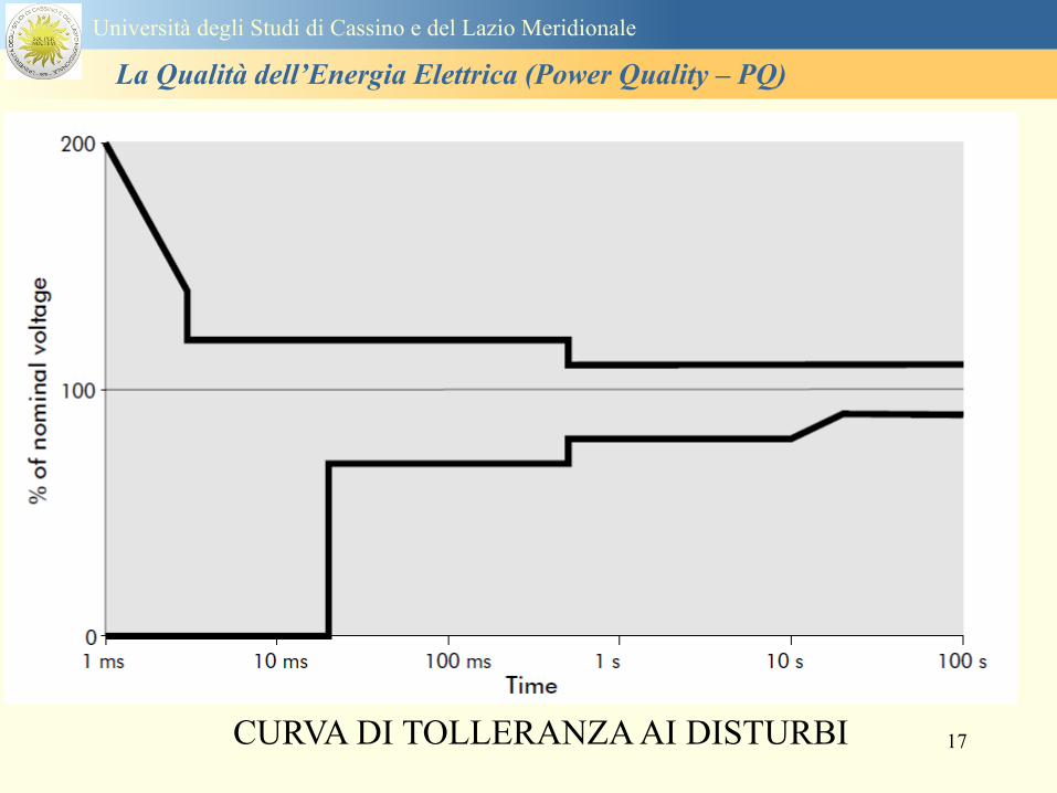
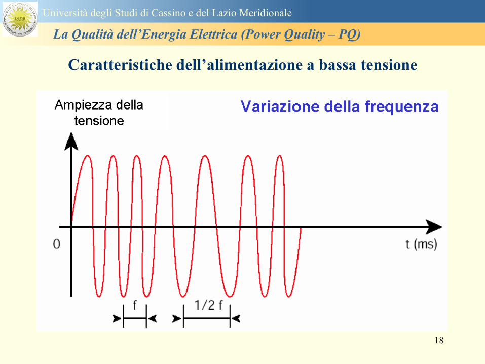
18
Caratteristiche dellrsquoalimentazione a bassa tensione
Universitagrave degli Studi di Cassino e del Lazio Meridionale
La Qualitagrave dellrsquoEnergia Elettrica (Power Quality ndash PQ)
19
Caratteristiche dellrsquoalimentazione a bassa tensione
Frequenza nominale
La frequenza nominale della tensione fornita deve essere di 50 Hz In condizioni normali
di esercizio il valore medio misurato nellrsquointervallo di 10 secondi deve essere
Per i sistemi con collegamento sincrono ad un sistema interconnesso
1 50 Hz plusmn 1 durante il 95 di un anno
2 50 Hz +4 - 6 durante il 100 di un anno
Per i sistemi senza collegamento sincrono ad un sistema interconnesso
1 50 Hz plusmn 2 durante il 95 di un anno
2 50 Hz plusmn 15 durante il 100 di un anno
Universitagrave degli Studi di Cassino e del Lazio Meridionale
La Qualitagrave dellrsquoEnergia Elettrica (Power Quality ndash PQ)
20
Caratteristiche dellrsquoalimentazione a bassa tensione
Universitagrave degli Studi di Cassino e del Lazio Meridionale
La Qualitagrave dellrsquoEnergia Elettrica (Power Quality ndash PQ)
21
Caratteristiche dellrsquoalimentazione a bassa tensione
Universitagrave degli Studi di Cassino e del Lazio Meridionale
La Qualitagrave dellrsquoEnergia Elettrica (Power Quality ndash PQ)
22
Variazioni della tensione di alimentazione (variazioni lente)
Le variazioni lente sono deviazioni ldquomedierdquo dal valore nominale dellrsquoampiezza della
tensione di consegna entro una fascia predefinita (per esempio del plusmn10) rispetto alla
tensione dichiarata
CAUSE variazione lenta dei carichi e dalla corrispondente azione di regolazione effettuata dai
variatori sotto carico dei trasformatori
Universitagrave degli Studi di Cassino e del Lazio Meridionale
La Qualitagrave dellrsquoEnergia Elettrica (Power Quality ndash PQ)
23
Variazioni della tensione di alimentazione (variazioni rapide)
Le variazioni rapide sono abbassamenti (o aumenti) bruschi di qualche percento della
tensione preesistente generalmente seguiti se abbassamenti da un ritorno (a rampa o di
altra forma) ad un valore intermedio tra quello preesistente e tra il minimo raggiunto
CAUSE commutazione dei carichi (partenza motori in particolare) funzionamento di carichi
con ciclo operativo particolarmente variabile e in qualche caso da manovre in rete (linee
trasformatori condensatori ecc)
Universitagrave degli Studi di Cassino e del Lazio Meridionale
La Qualitagrave dellrsquoEnergia Elettrica (Power Quality ndash PQ)
24
Flicker Il flicker egrave originato dalla fluttuazione della tensione Si definisce fluttuazione di tensione una
serie di variazioni rapide (uguali o diverse) della tensione
Fluttuazioni di tensione che presentano frequenze di modulazione del 50 Hz comprese tra 05 e
40 Hz danno origine al fenomeno del flicker (sfarfallio) ovvero della sensazione visiva
provocata dalle fluttuazioni dellrsquointensitagrave di illuminazione delle lampade
I suoi principali effetti sullrsquouomo possono essere mal di testa irritabilitagrave e fastidio agli occhi
Universitagrave degli Studi di Cassino e del Lazio Meridionale
La Qualitagrave dellrsquoEnergia Elettrica (Power Quality ndash PQ)
25
Universitagrave degli Studi di Cassino e del Lazio Meridionale
La Qualitagrave dellrsquoEnergia Elettrica (Power Quality ndash PQ)
26
La Qualitagrave dellrsquoEnergia Elettrica (Power Quality ndash PQ)
Universitagrave degli Studi di Cassino e del Lazio Meridionale
La Qualitagrave dellrsquoEnergia Elettrica (Power Quality ndash PQ)
27
Universitagrave degli Studi di Cassino e del Lazio Meridionale
La Qualitagrave dellrsquoEnergia Elettrica (Power Quality ndash PQ)
28
Universitagrave degli Studi di Cassino e del Lazio Meridionale
La Qualitagrave dellrsquoEnergia Elettrica (Power Quality ndash PQ)
29
Universitagrave degli Studi di Cassino e del Lazio Meridionale
La Qualitagrave dellrsquoEnergia Elettrica (Power Quality ndash PQ)
30
Universitagrave degli Studi di Cassino e del Lazio Meridionale
La Qualitagrave dellrsquoEnergia Elettrica (Power Quality ndash PQ)
31
Universitagrave degli Studi di Cassino e del Lazio Meridionale
La Qualitagrave dellrsquoEnergia Elettrica (Power Quality ndash PQ)
32
Buchi di tensione Riduzione temporanea della tensione in un punto della rete elettrica sotto una determinata
soglia Se durante un buco la tensione scende sotto una soglia di interruzione lrsquoevento egrave
considerato essere sia un buco che unrsquointerruzione
CAUSE I buchi di tensione sono generalmente dovuti a guasti che sopravvengono negli
impianti utilizzatori o nel sistema di distribuzione pubblico Possono dipendere anche variazioni
di carico lungo la linea
Universitagrave degli Studi di Cassino e del Lazio Meridionale
La Qualitagrave dellrsquoEnergia Elettrica (Power Quality ndash PQ)
33
Interruzioni della tensione di alimentazione Condizione in cui la tensione ad un terminale della rete egrave inferiore allrsquo1 della tensione
nominale per una durata fino a tre minuti (brevi) o maggiori di 3 minuti (lunghe)
Universitagrave degli Studi di Cassino e del Lazio Meridionale
La Qualitagrave dellrsquoEnergia Elettrica (Power Quality ndash PQ)
34
Sovratensioni temporanee alla frequenza di rete fra fasi e terra Le sovratensioni sono sopraelevazioni della tensione conseguenti a modificazioni dello
stato elettrico della rete elettrica
Universitagrave degli Studi di Cassino e del Lazio Meridionale
La Qualitagrave dellrsquoEnergia Elettrica (Power Quality ndash PQ)
35
Armoniche Le armoniche sono tensioni o correnti sinusoidali con frequenza pari ad un multiplo intero
(ordine) della frequenza fondamentale di funzionamento del sistema elettrico la cui
presenza determina una distorsione della forma drsquoonda della tensione di alimentazione
CAUSE In piccola parte dal sistema stesso (trasformatori etc) e per la maggior parte da
apparecchi utilizzatori carichi commutati elettronicamente raddrizzatori convertitori regolatori
in AC cicloconvertitori ecc carichi con caratteristiche non lineari apparecchiature a
saturazione magnetica lampade a scarica forni ad arco saldatrici ad arco trasformatori ecc
bull carichi inseriti e disinseriti da organi di manovra condensatori filtri e motori a induzione
Universitagrave degli Studi di Cassino e del Lazio Meridionale
La Qualitagrave dellrsquoEnergia Elettrica (Power Quality ndash PQ)
36
Armoniche di tensione e corrente ndash Problemi
Vi sono diversi ambiti causati dalle armoniche
bull problemi causati da armoniche di corrente
1048707 sovraccarico del neutro
1048707 aumento delle perdite nei trasformatori
1048707 interventi intempestivi degli interruttori automatici
1048707 aumento dellrsquoeffetto pelle
bull problemi causati da armoniche di tensione
1048707 deformazione della tensione
1048707 disturbi nella coppia dei motori ad induzione
1048707 rumore al passaggio per lo zero
bull problemi causati quando le armoniche di corrente raggiungono lrsquoalimentazione
Universitagrave degli Studi di Cassino e del Lazio Meridionale
La Qualitagrave dellrsquoEnergia Elettrica (Power Quality ndash PQ)
37
38
Universitagrave degli Studi di Cassino e del Lazio Meridionale
La Qualitagrave dellrsquoEnergia Elettrica (Power Quality ndash PQ)
39
Strumentazione ldquohand heldrdquo con display
Universitagrave degli Studi di Cassino e del Lazio Meridionale
La Qualitagrave dellrsquoEnergia Elettrica (Power Quality ndash PQ)
40
Strumentazione ldquohand heldrdquo con display
Universitagrave degli Studi di Cassino e del Lazio Meridionale
La Qualitagrave dellrsquoEnergia Elettrica (Power Quality ndash PQ)
41
Strumentazione da registrazione
Universitagrave degli Studi di Cassino e del Lazio Meridionale
La Qualitagrave dellrsquoEnergia Elettrica (Power Quality ndash PQ)
42
Schema di principio ndash 61000-4-30 copy IEC2008
The electrical quantity to be measured may be either directly accessible as is
generally the case in low-voltage systems or accessible via measurement
transducers
An instrument may include the whole measurement chain In this standard the
normative part does not consider the measurement transducers external to the
instrument and their associated uncertainty
Universitagrave degli Studi di Cassino e del Lazio Meridionale
La Qualitagrave dellrsquoEnergia Elettrica (Power Quality ndash PQ)
43
Universitagrave degli Studi di Cassino Corso di Fondamenti di Misure
La Qualitagrave dellrsquoEnergia Elettrica (Power Quality ndash PQ)
Classi dei metodi di misura - 61000-4-30 copy IEC2008
For each class measurement methods and appropriate performance requirements
are included
Sono definite tre classi A S e B
Class A
This class is used where precise measurements are necessary for example for contractual
applications that may require resolving disputes verifying compliance with standards etc
Any measurements of a parameter carried out with two different instruments complying with
the requirements of Class A when measuring the same signals will produce matching results
within the specified uncertainty for that parameter
Class S
This class is used for statistical applications such as surveys or power quality assessment
possibly with a limited subset of parameters Although it uses equivalent intervals of
measurement as class A the class S processing requirements are lower
Class B
This class is defined in order to avoid making many existing instruments designs obsolete
NOTE Class B methods are not recommended for new designs Readers are advised that Class B may be removed in a
future Edition of this standard
44
Classi dei metodi di misura - 61000-4-30 copy IEC2008
Measurement aggregation over time intervals
CLASS A
The basic measurement time interval for parameter magnitudes (supply voltage harmonics
interharmonics and unbalance) shall be a 10-cycle time interval for a 50 Hz power system
or 12-cycle time interval for a 60 Hz power system
The 1012-cycle measurement shall be re-synchronized at every RTC 10 min tick
The 1012-cycle values are then aggregated over 3 additional intervals
ndash 150180-cycle interval (150 cycles for 50 Hz nominal or 180 cycles for 60 Hz nominal)
ndash 10 min interval
ndash 2 h interval
CLASS S
Same time intervals as Class A
CLASS B
The manufacturer shall specify the number and duration of aggregation time intervals
Universitagrave degli Studi di Cassino e del Lazio Meridionale
La Qualitagrave dellrsquoEnergia Elettrica (Power Quality ndash PQ)
45
Universitagrave degli Studi di Cassino e del Lazio Meridionale
La Qualitagrave dellrsquoEnergia Elettrica (Power Quality ndash PQ)
46
Universitagrave degli Studi di Cassino e del Lazio Meridionale
La Qualitagrave dellrsquoEnergia Elettrica (Power Quality ndash PQ)
Class A
The 10-min aggregated value shall be tagged with the absolute time (for
example 01H1000) The time tag is the time at the conclusion of the 10-min
aggregation
The data for the 10-min time interval shall be aggregated from 1012-cycle time
intervals
Each 10-minute interval shall begin on a UTC 10-min tick The 10-min tick is
also used to re-synchronize the 1012-cycle intervals and the 150180-cycle
intervals
The final 1012-cycle interval(s) in a 10-min aggregation period will typically
overlap in time with the UTC 10-min clock tick Any overlapping 1012-cycle
interval (Overlap 1 in Figure 2) is included in the aggregation of the previous
10-min interval
47
Universitagrave degli Studi di Cassino e del Lazio Meridionale
La Qualitagrave dellrsquoEnergia Elettrica (Power Quality ndash PQ)
48
Universitagrave degli Studi di Cassino e del Lazio Meridionale
La Qualitagrave dellrsquoEnergia Elettrica (Power Quality ndash PQ)
49
Classi dei metodi di misura - 61000-4-30 copy IEC2008
Real time clock (RTC) uncertainty
Sono definite le specifiche per le 3 classi
Flagging concept
During a dip swell or interruption the measurement algorithm for other
parameters (for example frequency measurement) might produce an unreliable
value The flagging concept therefore avoids counting a single event more than
once in different parameters (for example counting a single dip as both a dip and a
frequency variation) and indicates that an aggregated value might be unreliable
Universitagrave degli Studi di Cassino e del Lazio Meridionale
La Qualitagrave dellrsquoEnergia Elettrica (Power Quality ndash PQ)
50
Classi dei metodi di misura - 61000-4-30 copy IEC2008
Power quality parameters - INDICES
Per ogni parametro viene suggerito il metodo di misura per le tre classi e
(soprattutto) le caratteristiche di precisione Per alcuni parametri rimanda a
specifiche norme (ad esempio Flicker e Armonicheinterarmoniche)
Esempio - Power frequency Class A
The frequency reading shall be obtained every 10 s As power frequency may not be exactly 50 Hz or 60
Hz within the 10 s time clock interval the number of cycles may not be an integer number The
fundamental frequency output is the ratio of the number of integral cycles counted during the 10 s time
clock interval divided by the cumulative duration of the integer cycles Before each assessment
harmonics and interharmonics shall be attenuated to minimize the effects of multiple zero crossings
The measurement time intervals shall be non-overlapping Individual cycles that overlap the 10 s time
clock are discarded Each 10 s interval shall begin on an absolute 10 s time clock with uncertainty as
defined in 46
Other techniques that provide equivalent results such as convolution are acceptable
Class S Same as class A
Class B The manufacturer shall specify the process used for frequency measurement
Universitagrave degli Studi di Cassino e del Lazio Meridionale
La Qualitagrave dellrsquoEnergia Elettrica (Power Quality ndash PQ)
51
Classi dei metodi di misura - 61000-4-30 copy IEC2008
Power quality parameters - INDICES
Per ogni parametro viene suggerito il metodo di misura per le tre classi e
(soprattutto) le caratteristiche di precisione Per alcuni parametri rimanda a
specifiche norme (ad esempio Flicker e Armonicheinterarmoniche)
Esempio - Power frequency
Measurement uncertainty and measuring range
ndash Class A
Under the conditions described in 61 the measurement uncertainty shall not exceed
plusmn10 mHz over the measuring ranges 425 Hz ~ 575 Hz 51 Hz ~ 69 Hz
ndash Class S
Under the conditions described in 61 the measurement uncertainty shall not exceed
plusmn50 mHz over the measuring ranges 425 Hz ~ 575 Hz 51 Hz ~ 69 Hz
ndash Class B
The manufacturer shall specify the uncertainty over the measuring ranges 425 Hz ~
575 Hz 51 Hz ~ 69 Hz
Universitagrave degli Studi di Cassino e del Lazio Meridionale
La Qualitagrave dellrsquoEnergia Elettrica (Power Quality ndash PQ)
52
Magnitude of the supply voltage
Measurement method
ndash Class A
The measurement shall be the rms value of the voltage magnitude over
a 10-cycle time interval for 50 Hz power system or 12-cycle time
interval for 60 Hz power system Every 1012-cycle interval shall be
contiguous and not overlapping with adjacent 1012-cycle intervals
except as shown as Overlap 1 in Figure 2
NOTE 1 This specific measurement method is used for quasi-stationary signals and is
not used for the detection and measurement of disturbances dips swells voltage
interruptions and transients
NOTE 2 The rms value includes by definition harmonics interharmonics mains
signalling etc
- Class S same as Class A
Universitagrave degli Studi di Cassino e del Lazio Meridionale
La Qualitagrave dellrsquoEnergia Elettrica (Power Quality ndash PQ)
53
Magnitude of the supply voltage
Measurement uncertainty and measuring range
ndash Class A
Under the conditions described in Clause 6 the measurement uncertainty
shall not exceed plusmn01 of Udin over the range of 10 ~ 150 of Udin
ndash Class S
Under the conditions described in Clause 6 the measurement uncertainty
shall not exceed plusmn05 of Udin over the range of 20 ~ 120 of Udin
Universitagrave degli Studi di Cassino e del Lazio Meridionale
La Qualitagrave dellrsquoEnergia Elettrica (Power Quality ndash PQ)
54
Supply voltage dips and swells
Measurement method
ndash Class A
The basic measurement Urms of a voltage dip and swell shall be the
Urms(frac12) on each measurement channel (see Clause 322)
The cycle duration for Urms(frac12) depends on the frequency The
frequency might be determined by the last non-flagged power frequency
measurement (see Clause 47 and Clause 51) or by any other method
that yields the uncertainty requirements of Clause 6
NOTE 1 The Urms(frac12) value includes by definition harmonics interharmonics mains
signalling voltage etc
NOTE 2 It is important to avoid loss of data when dips and swells occur in a rapid
sequence (for example three events in one second with up to one minute between
sequences may occur when a recloser operates into a sustained fault) If during a rapid
burst the dipswell event characteristics cannot be recorded then a count of events may
be useful
Universitagrave degli Studi di Cassino e del Lazio Meridionale
La Qualitagrave dellrsquoEnergia Elettrica (Power Quality ndash PQ)
55
Supply voltage dips and swells
Detection and evaluation of a voltage dip
Voltage dip detection
The dip threshold is a percentage of either Udin or the sliding voltage
reference Usr (see 525 544) The user shall declare the reference
voltage in use
NOTE ndash On single-phase systems a voltage dip begins when the Urms voltage falls
below the dip threshold and ends when the Urms voltage is equal to or above the dip
threshold plus the hysteresis voltage
ndash On polyphase systems a dip begins when the Urms voltage of one or more channels is
below the dip threshold and ends when the Urms voltage on all measured channels is
equal to or above the dip threshold plus the hysteresis voltage
The dip threshold and the hysteresis voltage are both set by the user according to the
use
Universitagrave degli Studi di Cassino e del Lazio Meridionale
La Qualitagrave dellrsquoEnergia Elettrica (Power Quality ndash PQ)
56
Calculation of a sliding reference voltage
The sliding reference voltage implementation is optional not mandatory
If a sliding reference is chosen for voltage dip or swell detection this
shall be calculated using a first-order filter with a 1-min time constant
This filter is given by
Usr(n) = 09967 times Usr(nndash1) + 00033 times U(1012)rms
where
Usr(n) is the present value of the sliding reference voltage
Usr(nndash1) is the previous value of the sliding reference voltage and
U(1012)rms is the most recent 1012-cycle rms value
When the measurement is started the initial value of the sliding reference voltage is set
to the declared input voltage The sliding reference voltage is updated every 1012-
cycles If a 1012-cycle value is flagged the sliding reference voltage is not updated
and the previous value is used
Universitagrave degli Studi di Cassino e del Lazio Meridionale
La Qualitagrave dellrsquoEnergia Elettrica (Power Quality ndash PQ)
57
Supply voltage dips and swells
Voltage dip evaluation
A voltage dip is characterized by a pair of data either residual voltage
(Ures) or depth and duration
ndash the residual voltage of a voltage dip is the lowest Urms(frac12) value
measured on any channel during the dip
ndash the depth is the difference between the reference voltage (either Udin
or Usr) and the residual voltage It is generally expressed in percentage
of the reference voltage
NOTE 1 During the dip it may be useful to also record the lowest Urms(frac12) on each
channel in addition to the residual voltage of the dip The duration spent below the dip
threshold on each channel may also be useful
Universitagrave degli Studi di Cassino e del Lazio Meridionale
La Qualitagrave dellrsquoEnergia Elettrica (Power Quality ndash PQ)
58
Supply voltage dips and swells
Voltage dip evaluation
NOTE 2 If voltage waveforms are recorded before during and after a
dip useful information about phase angle changes may be available in
the recorded data
The start time of a dip shall be time stamped with the time of the start of
the Urms of the channel that initiated the event and the end time of the
dip shall be the time stamped with the time of the end of the Urms that
ended the event as defined by the threshold plus the hysteresis
The duration of a voltage dip is the time difference between the start
time and the end time of the voltage dip
Universitagrave degli Studi di Cassino e del Lazio Meridionale
La Qualitagrave dellrsquoEnergia Elettrica (Power Quality ndash PQ)
59
Supply voltage dips and swells
Residual voltage and swell voltage magnitude measurement
uncertainty
ndash Class A
The measurement uncertainty shall not exceed plusmn02 of Udin
ndash Class S
The measurement uncertainty shall not exceed plusmn10 of Udin
Universitagrave degli Studi di Cassino e del Lazio Meridionale
La Qualitagrave dellrsquoEnergia Elettrica (Power Quality ndash PQ)
60
Schema di principio ndash 61000-4-7 copy IEC2002
Universitagrave degli Studi di Cassino e del Lazio Meridionale
La Qualitagrave dellrsquoEnergia Elettrica (Power Quality ndash PQ)
61
Universitagrave degli Studi di Cassino e del Lazio Meridionale
La Qualitagrave dellrsquoEnergia Elettrica (Power Quality ndash PQ)
62
Universitagrave degli Studi di Cassino e del Lazio Meridionale
La Qualitagrave dellrsquoEnergia Elettrica (Power Quality ndash PQ)
63
Inter-Armoniche Le inter-armoniche sono tensioni o correnti sinusoidali con frequenza diversa da un
multiplo intero della fondamentale la cui presenza determina una distorsione
(modulazione) della forma donda della tensione di alimentazione
CAUSE dai carichi che assorbono correnti inter-armoniche
- carichi commutati elettronicamente convertitori cascata subsincrona cicloconvertitori regolatori con
controllo a pacchetti di cicli ecc
- carichi con caratteristiche non lineari eo non stazionarie forni ad arco saldatrici ad arco ecc
Universitagrave degli Studi di Cassino e del Lazio Meridionale
La Qualitagrave dellrsquoEnergia Elettrica (Power Quality ndash PQ)
64
Universitagrave degli Studi di Cassino e del Lazio Meridionale
La Qualitagrave dellrsquoEnergia Elettrica (Power Quality ndash PQ)
Un porsquo di esempi e
consigli praticihellip
65
0V
50V
100V
150V
200V
250V
300V
350V
0ms 5ms 10ms 15ms 20ms
t
u
0A
1A
2A
3A
i
0V
50V
100V
150V
200V
250V
300V
350V
0ms 5ms 10ms 15ms 20ms
t
u
0A
1A
2A
3A
i
0V
50V
100V
150V
200V
250V
300V
350V
0ms 5ms 10ms 15ms 20ms
t
u
0A
1A
2A
3A
i
gleichgerichtete
Netzspannung
Kondensator-
spannung
gleichgerichteter
Netzstrom
The situation
today
bull Computed current and voltage profiles when a
230 V 58 W fluorescent lamp with an old-style
electronic ballast is driven on the phase wire of
a typical power distribution system
System voltage 230 V
System frequency 50 Hz
Source resistance 500 mW
Longitudinal induction 904 microH
System impedance 575 mW
Mean dc current 180 mA
Smoothing capacitance220 microF
66
And what about electronic ballasts that are rated over 25W
Introduce electronic power factor correction (PFC)
0V
20V
40V
60V
80V
100V
120V
140V
160V
180V
200V
220V
0deg 15deg 30deg 45deg
u
00A
03A
06A
09A
12A
i
67
Though todayrsquos ballasts are better if
rated gt25 W bull Only
the
small
ones
continu
e to
pollute
just like
PCs
TV sets
do
68
This leads to a number of
previously unknown effects bull 1 Deformed voltage curves
bull 2 Huge inrush current peaks
bull 3 Instrument dependent measured parameters
bull 4 Increased loading of phase conductors
bull 5 Loading and overloading of the neutral conductor
bull 6 Overheating and start-up problems of induction motors
bull 7 Additional stray losses in transformers
bull 8 Repercussions of generators upon the mains
bull 9 Influence of capacitors repercussions upon the mains
and four additional complications in TN-C systems
10 Stray currents in equipotential bonding system magnetic fields
11 Contamination of data streams by stray currents
12 Stray currents in the earthing system corrosion damage
13 Lightning currents in devices and equipment
69
1 Deformed voltage curves
bull in theory
-350V
-300V
-250V
-200V
-150V
-100V
-50V
0V
50V
100V
150V
200V
250V
300V
350V
0 5 10 15 20
t ms
u
System voltage profile when driving
a single-phase load comprising
twenty 58 W energy-saver lamps in
parallel on a typical 230 V power
system
70
and in practice
bull An actual
current profile
bull
bull and
bull a voltage profile
bull
bull recorded in a large storage
dispatch and administrative
building
71
at home or in industrial environments
bull
bull Television 40
W
bull 200 Vdiv 2
Adiv
bull 5 msdiv
Harmonic
spectrum
Frequency
converter
50 Adiv
Phase currents
I1=I2=I3=160 A
IN=295 A
5 msdiv
72
Every periodic waveform can be written
as the infinite sum of sinusoidal waves
-175
-150
-125
-100
-75
-50
-25
0
25
50
75
100
125
150
175
0 5 10 15 20
t ms
i
mA
itot
i1
Synthesis of a triangular current profile 100mA
Content fundamental I = 99 mA Isup2 = 9855 mAsup2
Sum of squares Isup2 = 9855 mAsup2
Root of sum = RMS value I = 99 mA
-175
-150
-125
-100
-75
-50
-25
0
25
50
75
100
125
150
175
0 5 10 15 20
t ms
i
mA
itot
i1
i3
Synthesis of a triangular current profile 100mA
Content fundamental I = 99 mA Isup2 = 9855 mAsup2
Cont 3 rd harmonic I = -11 mA Isup2 = 122 mAsup2
Sum of squares Isup2 = 9977 mAsup2
Root of sum = RMS value I = 100 mA
-175
-150
-125
-100
-75
-50
-25
0
25
50
75
100
125
150
175
0 5 10 15 20
t ms
i
mA
itot
i1
i3
i5
Synthesis of a triangular current profile 100mA
Content fundamental I = 99 mA Isup2 = 9855 mAsup2
Cont 3 rd harmonic I = -11 mA Isup2 = 122 mAsup2
Cont 5 th harmonic I = 4 mA Isup2 = 16 mAsup2
Sum of squares Isup2 = 9993 mAsup2
Root of sum = RMS value I = 100 mA
-175
-150
-125
-100
-75
-50
-25
0
25
50
75
100
125
150
175
0 5 10 15 20
t ms
i
mA
itot
i1
i3
i5
i7
Synthesis of a triangular current profile 100mA
Content fundamental I = 99 mA Isup2 = 9855 mAsup2
Cont 3 rd harmonic I = -11 mA Isup2 = 122 mAsup2
Cont 5 th harmonic I = 4 mA Isup2 = 16 mAsup2
Cont 7 th harmonic I = -2 mA Isup2 = 4 mAsup2
Sum of squares Isup2 = 9997 mAsup2
Root of sum = RMS value I = 100 mA
-175
-150
-125
-100
-75
-50
-25
0
25
50
75
100
125
150
175
0 5 10 15 20
t ms
i
mA
itot i1
i3 i5
i7 i9
Synthesis of a triangular current profile 100mA
Content fundamental I = 99 mA Isup2 = 9855 mAsup2
Cont 3 rd harmonic I = -11 mA Isup2 = 122 mAsup2
Cont 5 th harmonic I = 4 mA Isup2 = 16 mAsup2
Cont 7 th harmonic I = -2 mA Isup2 = 4 mAsup2
Cont 9 th harmonic I = 1 mA Isup2 = 2 mAsup2
Sum of squares Isup2 = 9998 mAsup2
Root of sum = RMS value I = 100 mA
-175
-150
-125
-100
-75
-50
-25
0
25
50
75
100
125
150
175
0 5 10 15 20
t ms
i
mA
itot i1
i3 i5
i7 i9
i11
Synthesis of a triangular current profile 100mA
Content fundamental I = 99 mA Isup2 = 9855 mAsup2
Cont 3 rd harmonic I = -11 mA Isup2 = 122 mAsup2
Cont 5 th harmonic I = 4 mA Isup2 = 16 mAsup2
Cont 7 th harmonic I = -2 mA Isup2 = 4 mAsup2
Cont 9 th harmonic I = 1 mA Isup2 = 2 mAsup2
Cont 11 th harmonic I = -1 mA Isup2 = 1 mAsup2
Sum of squares Isup2 = 9999 mAsup2
Root of sum = RMS value I = 100 mA
-175
-150
-125
-100
-75
-50
-25
0
25
50
75
100
125
150
175
0 5 10 15 20
t ms
i
mA
itot i1
i3 i5
i7 i9
i11 i13
Synthesis of a triangular current profile 100mA
Content fundamental I = 99 mA Isup2 = 9855 mAsup2
Cont 3 rd harmonic I = -11 mA Isup2 = 122 mAsup2
Cont 5 th harmonic I = 4 mA Isup2 = 16 mAsup2
Cont 7 th harmonic I = -2 mA Isup2 = 4 mAsup2
Cont 9 th harmonic I = 1 mA Isup2 = 2 mAsup2
Cont 11 th harmonic I = -1 mA Isup2 = 1 mAsup2
Cont 13 th harmonic I = 1 mA Isup2 = 0 mAsup2
Sum of squares Isup2 = 9999 mAsup2
Root of sum = RMS value I = 100 mA
-175
-150
-125
-100
-75
-50
-25
0
25
50
75
100
125
150
175
0 5 10 15 20
t ms
i
mA
itot i1
i3 i5
i7 i9
i11 i13
i15
Synthesis of a triangular current profile 100mA
Content fundamental I = 99 mA Isup2 = 9855 mAsup2
Cont 3 rd harmonic I = -11 mA Isup2 = 122 mAsup2
Cont 5 th harmonic I = 4 mA Isup2 = 16 mAsup2
Cont 7 th harmonic I = -2 mA Isup2 = 4 mAsup2
Cont 9 th harmonic I = 1 mA Isup2 = 2 mAsup2
Cont 11 th harmonic I = -1 mA Isup2 = 1 mAsup2
Cont 13 th harmonic I = 1 mA Isup2 = 0 mAsup2
Cont 15 th harmonic I = 0 mA Isup2 = 0 mAsup2
Sum of squares Isup2 = 10000 mAsup2
Root of sum = RMS value I = 100 mA
-175
-150
-125
-100
-75
-50
-25
0
25
50
75
100
125
150
175
0 5 10 15 20
t ms
i
mA
itot i1
i3 i5
i7 i9
i11 i13
i15 i17
Synthesis of a triangular current profile 100mA
Content fundamental I = 99 mA Isup2 = 9855 mAsup2
Cont 3 rd harmonic I = -11 mA Isup2 = 122 mAsup2
Cont 5 th harmonic I = 4 mA Isup2 = 16 mAsup2
Cont 7 th harmonic I = -2 mA Isup2 = 4 mAsup2
Cont 9 th harmonic I = 1 mA Isup2 = 2 mAsup2
Cont 11 th harmonic I = -1 mA Isup2 = 1 mAsup2
Cont 13 th harmonic I = 1 mA Isup2 = 0 mAsup2
Cont 15 th harmonic I = 0 mA Isup2 = 0 mAsup2
Cont 17 th harmonic I = 0 mA Isup2 = 0 mAsup2
Sum of squares Isup2 = 10000 mAsup2
Root of sum = RMS value I = 100 mA
73
whose frequencies called harmonics are
integer multiples of the fundamental frequency
-175
-150
-125
-100
-75
-50
-25
0
25
50
75
100
125
150
175
0 5 10 15 20
t ms
i
mA
itot
i1
Synthesis of a rectangular current profile 100mA
Content fundamental I = 90 mA Isup2 = 8106 mAsup2
Sum of squares Isup2 = 8106 mAsup2
Root of sum = RMS value I = 90 mA
-175
-150
-125
-100
-75
-50
-25
0
25
50
75
100
125
150
175
0 5 10 15 20
t ms
i
mA
itot
i1
i3
Synthesis of a rectangular current profile 100mA
Content fundamental I = 90 mA Isup2 = 8106 mAsup2
Cont 3 rd harmonic I = 30 mA Isup2 = 901 mAsup2
Sum of squares Isup2 = 9006 mAsup2
Root of sum = RMS value I = 95 mA
-175
-150
-125
-100
-75
-50
-25
0
25
50
75
100
125
150
175
0 5 10 15 20
t ms
i
mA
itot
i1
i3
i5
Synthesis of a rectangular current profile 100mA
Content fundamental I = 90 mA Isup2 = 8106 mAsup2
Cont 3 rd harmonic I = 30 mA Isup2 = 901 mAsup2
Cont 5 th harmonic I = 18 mA Isup2 = 324 mAsup2
Sum of squares Isup2 = 9331 mAsup2
Root of sum = RMS value I = 97 mA
-175
-150
-125
-100
-75
-50
-25
0
25
50
75
100
125
150
175
0 5 10 15 20
t ms
i
mA
itot
i1
i3
i5
i7
Synthesis of a rectangular current profile 100mA
Content fundamental I = 90 mA Isup2 = 8106 mAsup2
Cont 3 rd harmonic I = 30 mA Isup2 = 901 mAsup2
Cont 5 th harmonic I = 18 mA Isup2 = 324 mAsup2
Cont 7 th harmonic I = 13 mA Isup2 = 165 mAsup2
Sum of squares Isup2 = 9496 mAsup2
Root of sum = RMS value I = 97 mA
-175
-150
-125
-100
-75
-50
-25
0
25
50
75
100
125
150
175
0 5 10 15 20
t ms
i
mA
itot i1
i3 i5
i7 i9
Synthesis of a rectangular current profile 100mA
Content fundamental I = 90 mA Isup2 = 8106 mAsup2
Cont 3 rd harmonic I = 30 mA Isup2 = 901 mAsup2
Cont 5 th harmonic I = 18 mA Isup2 = 324 mAsup2
Cont 7 th harmonic I = 13 mA Isup2 = 165 mAsup2
Cont 9 th harmonic I = 10 mA Isup2 = 100 mAsup2
Sum of squares Isup2 = 9596 mAsup2
Root of sum = RMS value I = 98 mA
-175
-150
-125
-100
-75
-50
-25
0
25
50
75
100
125
150
175
0 5 10 15 20
t ms
i
mA
itot i1
i3 i5
i7 i9
i11
Synthesis of a rectangular current profile 100mA
Content fundamental I = 90 mA Isup2 = 8106 mAsup2
Cont 3 rd harmonic I = 30 mA Isup2 = 901 mAsup2
Cont 5 th harmonic I = 18 mA Isup2 = 324 mAsup2
Cont 7 th harmonic I = 13 mA Isup2 = 165 mAsup2
Cont 9 th harmonic I = 10 mA Isup2 = 100 mAsup2
Cont 11 th harmonic I = 8 mA Isup2 = 67 mAsup2
Sum of squares Isup2 = 9663 mAsup2
Root of sum = RMS value I = 98 mA
-175
-150
-125
-100
-75
-50
-25
0
25
50
75
100
125
150
175
0 5 10 15 20
t ms
i
mA
itot i1
i3 i5
i7 i9
i11 i13
Synthesis of a rectangular current profile 100mA
Content fundamental I = 90 mA Isup2 = 8106 mAsup2
Cont 3 rd harmonic I = 30 mA Isup2 = 901 mAsup2
Cont 5 th harmonic I = 18 mA Isup2 = 324 mAsup2
Cont 7 th harmonic I = 13 mA Isup2 = 165 mAsup2
Cont 9 th harmonic I = 10 mA Isup2 = 100 mAsup2
Cont 11 th harmonic I = 8 mA Isup2 = 67 mAsup2
Cont 13 th harmonic I = 7 mA Isup2 = 48 mAsup2
Sum of squares Isup2 = 9711 mAsup2
Root of sum = RMS value I = 99 mA
-175
-150
-125
-100
-75
-50
-25
0
25
50
75
100
125
150
175
0 5 10 15 20
t ms
i
mA
itot i1
i3 i5
i7 i9
i11 i13
i15
Synthesis of a rectangular current profile 100mA
Content fundamental I = 90 mA Isup2 = 8106 mAsup2
Cont 3 rd harmonic I = 30 mA Isup2 = 901 mAsup2
Cont 5 th harmonic I = 18 mA Isup2 = 324 mAsup2
Cont 7 th harmonic I = 13 mA Isup2 = 165 mAsup2
Cont 9 th harmonic I = 10 mA Isup2 = 100 mAsup2
Cont 11 th harmonic I = 8 mA Isup2 = 67 mAsup2
Cont 13 th harmonic I = 7 mA Isup2 = 48 mAsup2
Cont 15 th harmonic I = 6 mA Isup2 = 36 mAsup2
Sum of squares Isup2 = 9747 mAsup2
Root of sum = RMS value I = 99 mA
-175
-150
-125
-100
-75
-50
-25
0
25
50
75
100
125
150
175
0 5 10 15 20
t ms
i
mA
itot i1
i3 i5
i7 i9
i11 i13
i15 i17
Synthesis of a rectangular current profile 100mA
Content fundamental I = 90 mA Isup2 = 8106 mAsup2
Cont 3 rd harmonic I = 30 mA Isup2 = 901 mAsup2
Cont 5 th harmonic I = 18 mA Isup2 = 324 mAsup2
Cont 7 th harmonic I = 13 mA Isup2 = 165 mAsup2
Cont 9 th harmonic I = 10 mA Isup2 = 100 mAsup2
Cont 11 th harmonic I = 8 mA Isup2 = 67 mAsup2
Cont 13 th harmonic I = 7 mA Isup2 = 48 mAsup2
Cont 15 th harmonic I = 6 mA Isup2 = 36 mAsup2
Cont 17 th harmonic I = 5 mA Isup2 = 28 mAsup2
Sum of squares Isup2 = 9775 mAsup2
Root of sum = RMS value I = 99 mA
74
Even far better simulations are
available free of charge at
bull wwwpowerstandardscomMcEachern
75
-4A
-3A
-2A
-1A
0A
1A
2A
3A
4A
0ms 5ms 10ms 15ms 20ms
t
i
-4A
-3A
-2A
-1A
0A
1A
2A
3A
4A
0ms 5ms 10ms 15ms 20ms
t
i
Applying the Fourier
analysis to a real PC
current does not work
directly
bull
bull but it can be
modelled by a similar
triangular curve in
which not all of the
higher harmonics
have been included
Triangular current profile of
the same amplitude and a
pulse duty cycle of 17
Input current of a PC
with monitor
76
Analysis of the model triangular waveform
-400
-350
-300
-250
-200
-150
-100
-50
0
50
100
150
200
250
300
350
400
0 5 10 15 20
t ms
iI
itot(t) L1 [A] i1(t) L1 [A]
i3(t) L1 [A] i5(t) L1 [A]
i7(t) L1 [A] i9(t) L1 [A]
i11(t) L1 [A] i13(t) L1 [A]
i15(t) L1 [A] i17(t) L1 [A]
77
M3
Harmonics
Energy
(active
power)
L1
L2
L3
N
PE
Important
bull Harmonics are created within the loads
themselves and can flow ldquoupstreamrdquo to
contaminate the power system
78
-6A
-5A
-4A
-3A
-2A
-1A
0A
1A
2A
3A
4A
5A
6A
0ms 5ms 10ms 15ms 20ms
t
i
Squared values
Without
Fundamental 502 mA 251986 mAsup2 the fundamental
3rd harmonic -479 mA 229000 mAsup2 229000 mAsup2
5th harmonic 434 mA 188595 mAsup2 188595 mAsup2
7th harmonic -374 mA 139903 mAsup2 139903 mAsup2
9th harmonic 304 mA 92527 mAsup2 92527 mAsup2
11th harmonic -232 mA 53671 mAsup2 53671 mAsup2
13th harmonic 163 mA 26600 mAsup2 26600 mAsup2
15th harmonic -104 mA 10780 mAsup2 10780 mAsup2
17th harmonic 57 mA 3299 mAsup2 3299 mAsup2
Sum of the squares 996362 mAsup2 744377 mAsup2
Root thereof 998 mAeff THD = 863 mA
What actually is THD Example shown here triangular current
profile with an rms current of 1000 mA
and a pulse duty cycle of 17
THDr (root mean square) = 863mA1000mA = 86
THDf (fundamental) = 863mA502mA = 172
79
Effect on phase-to-neutral
and phase-to-phase voltages
bull Recorded
on June
30 2002
230 p
m
bull What
was the
matter
then
bull The
soccer
final
Germany
vs
Brazil
80
The triple-N harmonics drive
a circulating current in the
delta winding of a distribution
transformer
bull but the
bull voltage harmonics
propagate into the next
low-voltage power
distribution system
81 0V
50V
100V
150V
200V
250V
300V
350V
400V
450V
500V
550V
0 10 20 30 40 50
t ms
u
0A
10A
20A
30A
40A
50A
60A
70A
80A
90A
100A
110A
120A
130A
140A
150A
i
Switching on just as supply voltage passes through zero
0V
50V
100V
150V
200V
250V
300V
350V
400V
450V
500V
550V
0 10 20 30 40 50
t ms
u
0A
10A
20A
30A
40A
50A
60A
70A
80A
90A
100A
110A
120A
130A
140A
150A
i
Switching on just as supply voltage is at its peak
2 Huge inrush current peaks
ndash in theory
82
and in practice
bull Inrush current of a
compact energy-
saver lamp and its
effect on the system
voltage (recorded at
the Technical
University of
Budapest)
bull
83
enables us to infer what
happens when run by a
normal three-phase supply
The same fluorescent lamp
with a magnetic ballast
bull The behaviour measured
when connected to
a dc supply
bull
Behaviour of a 58 W fluorescent lamp connected to a dc
supply
0
20
40
60
80
100
120
140
160
180
200
0 200 400 600 800 1000 1200
i mA
u
V
Measurement
Behaviour of a 58 W fluorescent lamp connected to a dc
supply
0
20
40
60
80
100
120
140
160
180
200
0 200 400 600 800 1000 1200
i mA
u
V
MeasurementCalculation
-350
-300
-250
-200
-150
-100
-50
0
50
100
150
200
250
300
350
0 5 10 15 20
t ms
u
V
-10
-08
-06
-04
-02
00
02
04
06
08
10
i
A
Systems voltage
Current
-350
-300
-250
-200
-150
-100
-50
0
50
100
150
200
250
300
350
0 5 10 15 20
t ms
u
V
-10
-08
-06
-04
-02
00
02
04
06
08
10
i
A
Systems voltage
Lamp voltage
Current
84
Warning ldquoCompensationrdquo is not
always what you think it is
bull Distinguish
between
bull Reactive
power
compensatio
n
aka power
factor
correction
Remedial
measure
Parallel (or
sometimes series)
compensation
using capacitors
Filter circuits
tuned to the
individual harmonic
frequencies
Harmonic
compensation
85
5 (Over)loading the neutral conductor
bull Magnetic ballast Old-style electronic ballast
-25A
-20A
-15A
-10A
-05A
00A
05A
10A
15A
20A
25A
0 5 10 15 20
t ms i
i(t) N
-25A
-20A
-15A
-10A
-05A
00A
05A
10A
15A
20A
25A
0 5 10 15 20
t ms
i
i(t) N
-25A
-20A
-15A
-10A
-05A
00A
05A
10A
15A
20A
25A
0 5 10 15 20
t ms
i
i(t) L1 i(t) L2 i(t) L3
-25A
-20A
-15A
-10A
-05A
00A
05A
10A
15A
20A
25A
0 5 10 15 20
t ms
i
i(t) L1
i(t) L2
i(t) L3
86
Adding the 3rd
harmonics
in the
neutral
wire
-150-100-50
050
100150
0deg 30deg 60deg 90deg 120deg 150deg 180deg 210deg 240deg 270deg 300deg 330deg 360deg
L1
-150-100-50
050
100150
0deg 30deg 60deg 90deg 120deg 150deg 180deg 210deg 240deg 270deg 300deg 330deg 360deg
L2
-150-100-50
050
100150
0deg 30deg 60deg 90deg 120deg 150deg 180deg 210deg 240deg 270deg 300deg 330deg 360deg
L3
-450-400-350-300-250-200-150-100-50
050
100150200250300350400450
0deg 30deg 60deg 90deg 120deg 150deg 180deg 210deg 240deg 270deg 300deg 330deg 360deg
f
iicirc
N
Physics dictates
that at any
moment in time
the phase and
neutral currents
must sum to zero
87
Effect on a three-phase ac motor
appears almost identical
bull The same motor is being
driven
simultaneously in
these three modes
homopolar system
zero-sequence system
direct system
positive-sequence system
inverse system
negative-sequence system
88
The transformer
influences the load
89
but the load also effects
the transformer
Total transformer loss is
2
)()(
nom
nomCunomFeLossI
IPPP
While total transformer loss really is
2
)(
2
)(
2
)(
nomnom
nomad
nom
nomCu
nom
nomFeLossI
I
f
fP
I
IP
U
UPP
90
6 ldquosupplementaryrdquo additional losses
in transformers
can be calculated rapidly
using the following two
simple formulae 50
2
2
1
2
11
Nn
n
nqh
I
In
I
I
e
eK
50
1
2
1
1
50
1
2
Nn
n
nNn
n
nI
IIII
where
Oh well
perhaps a practical
example is clearer
1000 compact 11W
(15VA) energy-saver
lamps powered by a
15kVA transformer
uSC=4 Pa=01PCu
Harmonics of an Osram Dulux 11W
CFL and a serial impedance of
R =291Ω amp X L=113Ω
U U sup2 I L I Lsup2 P aP Cu
n V Vsup2 mA mAsup2
1 2302 529920 485 23523 56
3 83 689 371 13764 295
5 107 1145 203 4121 245
7 43 185 53 281 33
9 11 12 30 90 17
11 23 53 38 144 42
13 10 10 15 23 09
15 06 04 15 23 12
17 11 12 15 23 15
19 05 03 09 08 07
21 05 03 13 17 18
23 06 04 08 06 08
25 04 02 06 04 05
27 06 04 08 06 11
29 04 02 05 03 05
31 03 01 05 03 06
33 03 01 05 03 06
35 03 01 04 02 05
37 03 01 04 02 05
39 03 01 03 01 03
41 01 00 03 01 04
43 02 00 02 00 02
45 01 00 02 00 02
47 01 00 02 00 02
49 01 00 01 00 01
51 01 00 01 00 01
P aP Cu = 814814
etc
etc
91
Harmonics measurement on an
Osram Dulux 11W compact
fluorescent lamp
U U sup2 I L I Lsup2 P addP Cu
n V Vsup2 mA mAsup2
1 2327 541493 489 23912 37
3 06 04 391 15288 215
5 44 194 264 6970 273
7 23 53 200 4000 307
9 01 00 192 3686 467
11 01 00 166 2756 522
13 01 00 127 1613 427
15 01 00 110 1210 426
17 01 00 102 1040 471
19 01 00 87 757 428
21 01 00 77 593 409
23 01 00 73 533 441
25 01 00 61 372 364
27 01 00 49 240 274
29 01 00 42 176 232
31 01 00 36 130 195
33 01 00 30 90 153
35 01 00 33 109 209
37 01 00 31 96 206
39 01 00 25 63 149
41 01 00 25 63 164
43 01 00 25 63 181
45 01 00 19 36 114
47 01 00 18 32 112
49 01 00 19 36 136
51 01 00 16 26 104
P aP Cu = 7017
To some extent
the transformer
protects itself
bull Always remember to
consider it
bull If the influence of the
transformer upon the load
did not exist then the
influence of the load upon
the transformer would be
nearly 9 times as high
7017
etc
etc
92
Rule of thumb Select transformers 35
larger than specification by apparent
power would require
bull This suffices to err
on the safe side
even in the worst
case and can
hardly ever be
wrong since
maximum
efficiency always
lies between 25
and 50 of rated
load
Efficiency of a 1 MVA transformer plotted against loading
985
986
987
988
989
990
991
992
993
994
0 25 50 75 100 125
Relative load h
Design with max Cu loss and min Fe loss
Design with min Cu loss and max Fe loss
1 MVA oil transformer according to HD 428
93
Measured response of an 11 W
fluorescent lamp operated with a
magnetic ballast
94
We are
dealing with
a complex
problem
bull These
effects
are not
isolated
but are
mutuall
y inter-
depende
nt
Effects 2 3 and 5 can be demonstrated
on DKIrsquos display panel
95
A conventional approximately resistive-
inductive load
mA
N L1 L2 L3
Two conventional approximately
resistive-inductive loads Three conventional approximately
resistive-inductive loads
96
A modern electronic load
mA
N
Two modern electronic loads Three modern electronic loads
L1 L2 L3
97
Discoveries on a
refurbished
junction box
System voltage
(as trigger
signal)
Current in the
earthing
conductor
between the
consumer unit
and the
bonding
busbar
98
The TN-C system that was perfectly
adequate some years ago is unable to meet
present-day requirements
-6
-4
-2
0
2
4
6
0 5 10 15 20
t ms
i
A
-350
-300
-250
-200
-150
-100
-50
0
50
100
150
200
250
300
350
0 5 10 15 20
t ms
u
V
99
ldquoTHFrdquo
(third harmonic
filter) made in
Finland
In certain situations this affordable
filter can be of help
German
version ldquoTHXrdquo
100
0Ω
5 Ω
1 0 Ω
1 5 Ω
2 0 Ω
2 5 Ω
3 0 Ω
3 5 Ω
4 0 Ω
0Hz 50Hz 100Hz 150Hz 200Hz 250Hz 300Hz
f
Z
-90deg
-75deg
-60deg
-45deg
-30deg
-15deg
0deg
15deg
30deg
45deg
60deg
75deg
90deg
φ
Reactorreactance
Capacitorreactance
Parallelimpedace
Phase angle
Data and frequency response
of the filter
bull 1320 microF
bull 875
14 mW microH
101
The filter in use
bull In a nursery running sodium vapour lamps (500 kW)
In a typical office and administrative building
102
The EMC Transformer from Switzerland
7 The effects of stray magnetic fields
in TN-C systems
bull ldquoWhen we build transformers the first thing we focus on is complying with our customersrsquo
requirements and only then on complying with standards Why Because it is customer
needs and not standards that offer real scope for product innovationrdquo
103
8 In a TN-C system problems arise from data
streams and working currents mixing
bull Others who
have drawn
attention to
this source of
data
transmission
errors include
engineering
and insurance
companies experts
consultants and many
others besides
104
9 Increased corrosive damage
bull This (once) galvanized steel strip ndash the earth
electrode of a TN-C-S system ndash was located close
to the transformer station
Side facing
transformer
station
Side facing
transformer
station
Side facing away
from transformer
station
Side facing away
from transformer
station
105
bull WRONG RIGHT
Working currents have no place
in earthing systems and
protective conductors
106
10 Lightning currents
107
Which bridge to
cross which bridge to
burn
Sometimes you just donlsquot
believe what you see
This one will soon
look rather charred
IEC 60364-5-54
54343 If from any point of the installation the neutral and protective
functions are provided by separate conductors it is not permitted to
connect the neutral conductor to any other earthed part of the
installation
108
Well then the rest is no longer a
miracle
109
110
111
Another means of (over)loading the
neutral conductor
bull dc currents
Original ldquoFakerdquo
112
and their
effects U = 2285 V
I = 92 mA
P = 182 W
S = 209 VA
Q = 103 VAr
LF = 087
cos φ = 099
U = 2243 V
I = 126 A
P = 380 W
S = 2860 VA
Q = 2830 VAr
No-load current in a
toroidal-core
transformer
200 VA
-350-300
-250-200
-150-100
-500
50
100150
200250
300350
0 10 20 30 40
t ms
u
V
-12
-10
-8
-6
-4
-2
0
2
4
6
8
10
12
i
mA
Voltage
Current
No-load current in a toroidal-core
transformer 200 VA when
running a 1500 W
hairdryer at
half-power
in parallel
-350-300
-250-200
-150-100
-500
50
100150
200250
300350
0 5 10 15 20 25 30 35 40
t ms
u
V
-6
-5
-4
-3
-2
-1
0
1
2
3
4
5
6
i
A
Voltage
Current
113
The later models donlsquot do it any more
The EN 61000-3-2 has at least managed
to put an end to this approach
Domestic appliances Max 105 A of 2nd harmonic
114
An electrical engineering wonder
dc current generates ac voltage
115
Spicing things up with a pinch of HF
electronic halogen lamp transformers
116
Decorative HF reactors
117
Current and power loss as a function of voltage
00
02
04
06
08
10
12
14
16
18
0 40 80 120 160 200 240
U V
I
A
0
20
40
60
80
100
120
PV
W
I [A]
Pv [W]
Power loss capacitor voltage
and total voltage as a function of current
0
50
100
150
200
250
300
350
400
450
000 025 050 075 100 125 150
I A
U
V
0
5
10
15
20
25
30
35
40
45
50
PV
W
Utot [V] Eff
UR [V] Eff
Pv [W]
The passive
harmonic filter
made of readily
available
components
bull is both
reliable
118
and effective
bull befor
e
bull after
119
Half the solution has already been implemented
120
And if thatrsquos not enough
bull Passive filter circuits will do it
121
So what do we need to do
bull In low-voltage power distribution systems
Do not use cables in which the neutral or protective earth conductor has a
reduced cross-section
Use only 5-core cable Do not install TN-C- or TN-C-S systems
Be generous when dimensioning conductor cross-sections This helps to
reduce line voltage drops and thus reduces the effect of current distortions on
the voltage as well as lowering energy losses (see VDE 0298 Part 100)
Generously dimensioned conductors will have no problem coping with any
future increase in demand
Only use measuring instruments that display the true root mean square value
(TRMS meters)
In medium-voltage power distribution systems
Use a varied mix of distribution transformers with different vector groups
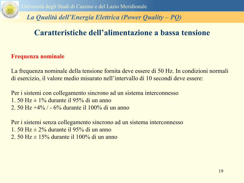
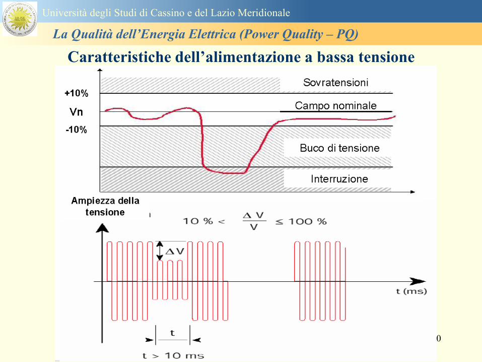
20
Caratteristiche dellrsquoalimentazione a bassa tensione
Universitagrave degli Studi di Cassino e del Lazio Meridionale
La Qualitagrave dellrsquoEnergia Elettrica (Power Quality ndash PQ)
21
Caratteristiche dellrsquoalimentazione a bassa tensione
Universitagrave degli Studi di Cassino e del Lazio Meridionale
La Qualitagrave dellrsquoEnergia Elettrica (Power Quality ndash PQ)
22
Variazioni della tensione di alimentazione (variazioni lente)
Le variazioni lente sono deviazioni ldquomedierdquo dal valore nominale dellrsquoampiezza della
tensione di consegna entro una fascia predefinita (per esempio del plusmn10) rispetto alla
tensione dichiarata
CAUSE variazione lenta dei carichi e dalla corrispondente azione di regolazione effettuata dai
variatori sotto carico dei trasformatori
Universitagrave degli Studi di Cassino e del Lazio Meridionale
La Qualitagrave dellrsquoEnergia Elettrica (Power Quality ndash PQ)
23
Variazioni della tensione di alimentazione (variazioni rapide)
Le variazioni rapide sono abbassamenti (o aumenti) bruschi di qualche percento della
tensione preesistente generalmente seguiti se abbassamenti da un ritorno (a rampa o di
altra forma) ad un valore intermedio tra quello preesistente e tra il minimo raggiunto
CAUSE commutazione dei carichi (partenza motori in particolare) funzionamento di carichi
con ciclo operativo particolarmente variabile e in qualche caso da manovre in rete (linee
trasformatori condensatori ecc)
Universitagrave degli Studi di Cassino e del Lazio Meridionale
La Qualitagrave dellrsquoEnergia Elettrica (Power Quality ndash PQ)
24
Flicker Il flicker egrave originato dalla fluttuazione della tensione Si definisce fluttuazione di tensione una
serie di variazioni rapide (uguali o diverse) della tensione
Fluttuazioni di tensione che presentano frequenze di modulazione del 50 Hz comprese tra 05 e
40 Hz danno origine al fenomeno del flicker (sfarfallio) ovvero della sensazione visiva
provocata dalle fluttuazioni dellrsquointensitagrave di illuminazione delle lampade
I suoi principali effetti sullrsquouomo possono essere mal di testa irritabilitagrave e fastidio agli occhi
Universitagrave degli Studi di Cassino e del Lazio Meridionale
La Qualitagrave dellrsquoEnergia Elettrica (Power Quality ndash PQ)
25
Universitagrave degli Studi di Cassino e del Lazio Meridionale
La Qualitagrave dellrsquoEnergia Elettrica (Power Quality ndash PQ)
26
La Qualitagrave dellrsquoEnergia Elettrica (Power Quality ndash PQ)
Universitagrave degli Studi di Cassino e del Lazio Meridionale
La Qualitagrave dellrsquoEnergia Elettrica (Power Quality ndash PQ)
27
Universitagrave degli Studi di Cassino e del Lazio Meridionale
La Qualitagrave dellrsquoEnergia Elettrica (Power Quality ndash PQ)
28
Universitagrave degli Studi di Cassino e del Lazio Meridionale
La Qualitagrave dellrsquoEnergia Elettrica (Power Quality ndash PQ)
29
Universitagrave degli Studi di Cassino e del Lazio Meridionale
La Qualitagrave dellrsquoEnergia Elettrica (Power Quality ndash PQ)
30
Universitagrave degli Studi di Cassino e del Lazio Meridionale
La Qualitagrave dellrsquoEnergia Elettrica (Power Quality ndash PQ)
31
Universitagrave degli Studi di Cassino e del Lazio Meridionale
La Qualitagrave dellrsquoEnergia Elettrica (Power Quality ndash PQ)
32
Buchi di tensione Riduzione temporanea della tensione in un punto della rete elettrica sotto una determinata
soglia Se durante un buco la tensione scende sotto una soglia di interruzione lrsquoevento egrave
considerato essere sia un buco che unrsquointerruzione
CAUSE I buchi di tensione sono generalmente dovuti a guasti che sopravvengono negli
impianti utilizzatori o nel sistema di distribuzione pubblico Possono dipendere anche variazioni
di carico lungo la linea
Universitagrave degli Studi di Cassino e del Lazio Meridionale
La Qualitagrave dellrsquoEnergia Elettrica (Power Quality ndash PQ)
33
Interruzioni della tensione di alimentazione Condizione in cui la tensione ad un terminale della rete egrave inferiore allrsquo1 della tensione
nominale per una durata fino a tre minuti (brevi) o maggiori di 3 minuti (lunghe)
Universitagrave degli Studi di Cassino e del Lazio Meridionale
La Qualitagrave dellrsquoEnergia Elettrica (Power Quality ndash PQ)
34
Sovratensioni temporanee alla frequenza di rete fra fasi e terra Le sovratensioni sono sopraelevazioni della tensione conseguenti a modificazioni dello
stato elettrico della rete elettrica
Universitagrave degli Studi di Cassino e del Lazio Meridionale
La Qualitagrave dellrsquoEnergia Elettrica (Power Quality ndash PQ)
35
Armoniche Le armoniche sono tensioni o correnti sinusoidali con frequenza pari ad un multiplo intero
(ordine) della frequenza fondamentale di funzionamento del sistema elettrico la cui
presenza determina una distorsione della forma drsquoonda della tensione di alimentazione
CAUSE In piccola parte dal sistema stesso (trasformatori etc) e per la maggior parte da
apparecchi utilizzatori carichi commutati elettronicamente raddrizzatori convertitori regolatori
in AC cicloconvertitori ecc carichi con caratteristiche non lineari apparecchiature a
saturazione magnetica lampade a scarica forni ad arco saldatrici ad arco trasformatori ecc
bull carichi inseriti e disinseriti da organi di manovra condensatori filtri e motori a induzione
Universitagrave degli Studi di Cassino e del Lazio Meridionale
La Qualitagrave dellrsquoEnergia Elettrica (Power Quality ndash PQ)
36
Armoniche di tensione e corrente ndash Problemi
Vi sono diversi ambiti causati dalle armoniche
bull problemi causati da armoniche di corrente
1048707 sovraccarico del neutro
1048707 aumento delle perdite nei trasformatori
1048707 interventi intempestivi degli interruttori automatici
1048707 aumento dellrsquoeffetto pelle
bull problemi causati da armoniche di tensione
1048707 deformazione della tensione
1048707 disturbi nella coppia dei motori ad induzione
1048707 rumore al passaggio per lo zero
bull problemi causati quando le armoniche di corrente raggiungono lrsquoalimentazione
Universitagrave degli Studi di Cassino e del Lazio Meridionale
La Qualitagrave dellrsquoEnergia Elettrica (Power Quality ndash PQ)
37
38
Universitagrave degli Studi di Cassino e del Lazio Meridionale
La Qualitagrave dellrsquoEnergia Elettrica (Power Quality ndash PQ)
39
Strumentazione ldquohand heldrdquo con display
Universitagrave degli Studi di Cassino e del Lazio Meridionale
La Qualitagrave dellrsquoEnergia Elettrica (Power Quality ndash PQ)
40
Strumentazione ldquohand heldrdquo con display
Universitagrave degli Studi di Cassino e del Lazio Meridionale
La Qualitagrave dellrsquoEnergia Elettrica (Power Quality ndash PQ)
41
Strumentazione da registrazione
Universitagrave degli Studi di Cassino e del Lazio Meridionale
La Qualitagrave dellrsquoEnergia Elettrica (Power Quality ndash PQ)
42
Schema di principio ndash 61000-4-30 copy IEC2008
The electrical quantity to be measured may be either directly accessible as is
generally the case in low-voltage systems or accessible via measurement
transducers
An instrument may include the whole measurement chain In this standard the
normative part does not consider the measurement transducers external to the
instrument and their associated uncertainty
Universitagrave degli Studi di Cassino e del Lazio Meridionale
La Qualitagrave dellrsquoEnergia Elettrica (Power Quality ndash PQ)
43
Universitagrave degli Studi di Cassino Corso di Fondamenti di Misure
La Qualitagrave dellrsquoEnergia Elettrica (Power Quality ndash PQ)
Classi dei metodi di misura - 61000-4-30 copy IEC2008
For each class measurement methods and appropriate performance requirements
are included
Sono definite tre classi A S e B
Class A
This class is used where precise measurements are necessary for example for contractual
applications that may require resolving disputes verifying compliance with standards etc
Any measurements of a parameter carried out with two different instruments complying with
the requirements of Class A when measuring the same signals will produce matching results
within the specified uncertainty for that parameter
Class S
This class is used for statistical applications such as surveys or power quality assessment
possibly with a limited subset of parameters Although it uses equivalent intervals of
measurement as class A the class S processing requirements are lower
Class B
This class is defined in order to avoid making many existing instruments designs obsolete
NOTE Class B methods are not recommended for new designs Readers are advised that Class B may be removed in a
future Edition of this standard
44
Classi dei metodi di misura - 61000-4-30 copy IEC2008
Measurement aggregation over time intervals
CLASS A
The basic measurement time interval for parameter magnitudes (supply voltage harmonics
interharmonics and unbalance) shall be a 10-cycle time interval for a 50 Hz power system
or 12-cycle time interval for a 60 Hz power system
The 1012-cycle measurement shall be re-synchronized at every RTC 10 min tick
The 1012-cycle values are then aggregated over 3 additional intervals
ndash 150180-cycle interval (150 cycles for 50 Hz nominal or 180 cycles for 60 Hz nominal)
ndash 10 min interval
ndash 2 h interval
CLASS S
Same time intervals as Class A
CLASS B
The manufacturer shall specify the number and duration of aggregation time intervals
Universitagrave degli Studi di Cassino e del Lazio Meridionale
La Qualitagrave dellrsquoEnergia Elettrica (Power Quality ndash PQ)
45
Universitagrave degli Studi di Cassino e del Lazio Meridionale
La Qualitagrave dellrsquoEnergia Elettrica (Power Quality ndash PQ)
46
Universitagrave degli Studi di Cassino e del Lazio Meridionale
La Qualitagrave dellrsquoEnergia Elettrica (Power Quality ndash PQ)
Class A
The 10-min aggregated value shall be tagged with the absolute time (for
example 01H1000) The time tag is the time at the conclusion of the 10-min
aggregation
The data for the 10-min time interval shall be aggregated from 1012-cycle time
intervals
Each 10-minute interval shall begin on a UTC 10-min tick The 10-min tick is
also used to re-synchronize the 1012-cycle intervals and the 150180-cycle
intervals
The final 1012-cycle interval(s) in a 10-min aggregation period will typically
overlap in time with the UTC 10-min clock tick Any overlapping 1012-cycle
interval (Overlap 1 in Figure 2) is included in the aggregation of the previous
10-min interval
47
Universitagrave degli Studi di Cassino e del Lazio Meridionale
La Qualitagrave dellrsquoEnergia Elettrica (Power Quality ndash PQ)
48
Universitagrave degli Studi di Cassino e del Lazio Meridionale
La Qualitagrave dellrsquoEnergia Elettrica (Power Quality ndash PQ)
49
Classi dei metodi di misura - 61000-4-30 copy IEC2008
Real time clock (RTC) uncertainty
Sono definite le specifiche per le 3 classi
Flagging concept
During a dip swell or interruption the measurement algorithm for other
parameters (for example frequency measurement) might produce an unreliable
value The flagging concept therefore avoids counting a single event more than
once in different parameters (for example counting a single dip as both a dip and a
frequency variation) and indicates that an aggregated value might be unreliable
Universitagrave degli Studi di Cassino e del Lazio Meridionale
La Qualitagrave dellrsquoEnergia Elettrica (Power Quality ndash PQ)
50
Classi dei metodi di misura - 61000-4-30 copy IEC2008
Power quality parameters - INDICES
Per ogni parametro viene suggerito il metodo di misura per le tre classi e
(soprattutto) le caratteristiche di precisione Per alcuni parametri rimanda a
specifiche norme (ad esempio Flicker e Armonicheinterarmoniche)
Esempio - Power frequency Class A
The frequency reading shall be obtained every 10 s As power frequency may not be exactly 50 Hz or 60
Hz within the 10 s time clock interval the number of cycles may not be an integer number The
fundamental frequency output is the ratio of the number of integral cycles counted during the 10 s time
clock interval divided by the cumulative duration of the integer cycles Before each assessment
harmonics and interharmonics shall be attenuated to minimize the effects of multiple zero crossings
The measurement time intervals shall be non-overlapping Individual cycles that overlap the 10 s time
clock are discarded Each 10 s interval shall begin on an absolute 10 s time clock with uncertainty as
defined in 46
Other techniques that provide equivalent results such as convolution are acceptable
Class S Same as class A
Class B The manufacturer shall specify the process used for frequency measurement
Universitagrave degli Studi di Cassino e del Lazio Meridionale
La Qualitagrave dellrsquoEnergia Elettrica (Power Quality ndash PQ)
51
Classi dei metodi di misura - 61000-4-30 copy IEC2008
Power quality parameters - INDICES
Per ogni parametro viene suggerito il metodo di misura per le tre classi e
(soprattutto) le caratteristiche di precisione Per alcuni parametri rimanda a
specifiche norme (ad esempio Flicker e Armonicheinterarmoniche)
Esempio - Power frequency
Measurement uncertainty and measuring range
ndash Class A
Under the conditions described in 61 the measurement uncertainty shall not exceed
plusmn10 mHz over the measuring ranges 425 Hz ~ 575 Hz 51 Hz ~ 69 Hz
ndash Class S
Under the conditions described in 61 the measurement uncertainty shall not exceed
plusmn50 mHz over the measuring ranges 425 Hz ~ 575 Hz 51 Hz ~ 69 Hz
ndash Class B
The manufacturer shall specify the uncertainty over the measuring ranges 425 Hz ~
575 Hz 51 Hz ~ 69 Hz
Universitagrave degli Studi di Cassino e del Lazio Meridionale
La Qualitagrave dellrsquoEnergia Elettrica (Power Quality ndash PQ)
52
Magnitude of the supply voltage
Measurement method
ndash Class A
The measurement shall be the rms value of the voltage magnitude over
a 10-cycle time interval for 50 Hz power system or 12-cycle time
interval for 60 Hz power system Every 1012-cycle interval shall be
contiguous and not overlapping with adjacent 1012-cycle intervals
except as shown as Overlap 1 in Figure 2
NOTE 1 This specific measurement method is used for quasi-stationary signals and is
not used for the detection and measurement of disturbances dips swells voltage
interruptions and transients
NOTE 2 The rms value includes by definition harmonics interharmonics mains
signalling etc
- Class S same as Class A
Universitagrave degli Studi di Cassino e del Lazio Meridionale
La Qualitagrave dellrsquoEnergia Elettrica (Power Quality ndash PQ)
53
Magnitude of the supply voltage
Measurement uncertainty and measuring range
ndash Class A
Under the conditions described in Clause 6 the measurement uncertainty
shall not exceed plusmn01 of Udin over the range of 10 ~ 150 of Udin
ndash Class S
Under the conditions described in Clause 6 the measurement uncertainty
shall not exceed plusmn05 of Udin over the range of 20 ~ 120 of Udin
Universitagrave degli Studi di Cassino e del Lazio Meridionale
La Qualitagrave dellrsquoEnergia Elettrica (Power Quality ndash PQ)
54
Supply voltage dips and swells
Measurement method
ndash Class A
The basic measurement Urms of a voltage dip and swell shall be the
Urms(frac12) on each measurement channel (see Clause 322)
The cycle duration for Urms(frac12) depends on the frequency The
frequency might be determined by the last non-flagged power frequency
measurement (see Clause 47 and Clause 51) or by any other method
that yields the uncertainty requirements of Clause 6
NOTE 1 The Urms(frac12) value includes by definition harmonics interharmonics mains
signalling voltage etc
NOTE 2 It is important to avoid loss of data when dips and swells occur in a rapid
sequence (for example three events in one second with up to one minute between
sequences may occur when a recloser operates into a sustained fault) If during a rapid
burst the dipswell event characteristics cannot be recorded then a count of events may
be useful
Universitagrave degli Studi di Cassino e del Lazio Meridionale
La Qualitagrave dellrsquoEnergia Elettrica (Power Quality ndash PQ)
55
Supply voltage dips and swells
Detection and evaluation of a voltage dip
Voltage dip detection
The dip threshold is a percentage of either Udin or the sliding voltage
reference Usr (see 525 544) The user shall declare the reference
voltage in use
NOTE ndash On single-phase systems a voltage dip begins when the Urms voltage falls
below the dip threshold and ends when the Urms voltage is equal to or above the dip
threshold plus the hysteresis voltage
ndash On polyphase systems a dip begins when the Urms voltage of one or more channels is
below the dip threshold and ends when the Urms voltage on all measured channels is
equal to or above the dip threshold plus the hysteresis voltage
The dip threshold and the hysteresis voltage are both set by the user according to the
use
Universitagrave degli Studi di Cassino e del Lazio Meridionale
La Qualitagrave dellrsquoEnergia Elettrica (Power Quality ndash PQ)
56
Calculation of a sliding reference voltage
The sliding reference voltage implementation is optional not mandatory
If a sliding reference is chosen for voltage dip or swell detection this
shall be calculated using a first-order filter with a 1-min time constant
This filter is given by
Usr(n) = 09967 times Usr(nndash1) + 00033 times U(1012)rms
where
Usr(n) is the present value of the sliding reference voltage
Usr(nndash1) is the previous value of the sliding reference voltage and
U(1012)rms is the most recent 1012-cycle rms value
When the measurement is started the initial value of the sliding reference voltage is set
to the declared input voltage The sliding reference voltage is updated every 1012-
cycles If a 1012-cycle value is flagged the sliding reference voltage is not updated
and the previous value is used
Universitagrave degli Studi di Cassino e del Lazio Meridionale
La Qualitagrave dellrsquoEnergia Elettrica (Power Quality ndash PQ)
57
Supply voltage dips and swells
Voltage dip evaluation
A voltage dip is characterized by a pair of data either residual voltage
(Ures) or depth and duration
ndash the residual voltage of a voltage dip is the lowest Urms(frac12) value
measured on any channel during the dip
ndash the depth is the difference between the reference voltage (either Udin
or Usr) and the residual voltage It is generally expressed in percentage
of the reference voltage
NOTE 1 During the dip it may be useful to also record the lowest Urms(frac12) on each
channel in addition to the residual voltage of the dip The duration spent below the dip
threshold on each channel may also be useful
Universitagrave degli Studi di Cassino e del Lazio Meridionale
La Qualitagrave dellrsquoEnergia Elettrica (Power Quality ndash PQ)
58
Supply voltage dips and swells
Voltage dip evaluation
NOTE 2 If voltage waveforms are recorded before during and after a
dip useful information about phase angle changes may be available in
the recorded data
The start time of a dip shall be time stamped with the time of the start of
the Urms of the channel that initiated the event and the end time of the
dip shall be the time stamped with the time of the end of the Urms that
ended the event as defined by the threshold plus the hysteresis
The duration of a voltage dip is the time difference between the start
time and the end time of the voltage dip
Universitagrave degli Studi di Cassino e del Lazio Meridionale
La Qualitagrave dellrsquoEnergia Elettrica (Power Quality ndash PQ)
59
Supply voltage dips and swells
Residual voltage and swell voltage magnitude measurement
uncertainty
ndash Class A
The measurement uncertainty shall not exceed plusmn02 of Udin
ndash Class S
The measurement uncertainty shall not exceed plusmn10 of Udin
Universitagrave degli Studi di Cassino e del Lazio Meridionale
La Qualitagrave dellrsquoEnergia Elettrica (Power Quality ndash PQ)
60
Schema di principio ndash 61000-4-7 copy IEC2002
Universitagrave degli Studi di Cassino e del Lazio Meridionale
La Qualitagrave dellrsquoEnergia Elettrica (Power Quality ndash PQ)
61
Universitagrave degli Studi di Cassino e del Lazio Meridionale
La Qualitagrave dellrsquoEnergia Elettrica (Power Quality ndash PQ)
62
Universitagrave degli Studi di Cassino e del Lazio Meridionale
La Qualitagrave dellrsquoEnergia Elettrica (Power Quality ndash PQ)
63
Inter-Armoniche Le inter-armoniche sono tensioni o correnti sinusoidali con frequenza diversa da un
multiplo intero della fondamentale la cui presenza determina una distorsione
(modulazione) della forma donda della tensione di alimentazione
CAUSE dai carichi che assorbono correnti inter-armoniche
- carichi commutati elettronicamente convertitori cascata subsincrona cicloconvertitori regolatori con
controllo a pacchetti di cicli ecc
- carichi con caratteristiche non lineari eo non stazionarie forni ad arco saldatrici ad arco ecc
Universitagrave degli Studi di Cassino e del Lazio Meridionale
La Qualitagrave dellrsquoEnergia Elettrica (Power Quality ndash PQ)
64
Universitagrave degli Studi di Cassino e del Lazio Meridionale
La Qualitagrave dellrsquoEnergia Elettrica (Power Quality ndash PQ)
Un porsquo di esempi e
consigli praticihellip
65
0V
50V
100V
150V
200V
250V
300V
350V
0ms 5ms 10ms 15ms 20ms
t
u
0A
1A
2A
3A
i
0V
50V
100V
150V
200V
250V
300V
350V
0ms 5ms 10ms 15ms 20ms
t
u
0A
1A
2A
3A
i
0V
50V
100V
150V
200V
250V
300V
350V
0ms 5ms 10ms 15ms 20ms
t
u
0A
1A
2A
3A
i
gleichgerichtete
Netzspannung
Kondensator-
spannung
gleichgerichteter
Netzstrom
The situation
today
bull Computed current and voltage profiles when a
230 V 58 W fluorescent lamp with an old-style
electronic ballast is driven on the phase wire of
a typical power distribution system
System voltage 230 V
System frequency 50 Hz
Source resistance 500 mW
Longitudinal induction 904 microH
System impedance 575 mW
Mean dc current 180 mA
Smoothing capacitance220 microF
66
And what about electronic ballasts that are rated over 25W
Introduce electronic power factor correction (PFC)
0V
20V
40V
60V
80V
100V
120V
140V
160V
180V
200V
220V
0deg 15deg 30deg 45deg
u
00A
03A
06A
09A
12A
i
67
Though todayrsquos ballasts are better if
rated gt25 W bull Only
the
small
ones
continu
e to
pollute
just like
PCs
TV sets
do
68
This leads to a number of
previously unknown effects bull 1 Deformed voltage curves
bull 2 Huge inrush current peaks
bull 3 Instrument dependent measured parameters
bull 4 Increased loading of phase conductors
bull 5 Loading and overloading of the neutral conductor
bull 6 Overheating and start-up problems of induction motors
bull 7 Additional stray losses in transformers
bull 8 Repercussions of generators upon the mains
bull 9 Influence of capacitors repercussions upon the mains
and four additional complications in TN-C systems
10 Stray currents in equipotential bonding system magnetic fields
11 Contamination of data streams by stray currents
12 Stray currents in the earthing system corrosion damage
13 Lightning currents in devices and equipment
69
1 Deformed voltage curves
bull in theory
-350V
-300V
-250V
-200V
-150V
-100V
-50V
0V
50V
100V
150V
200V
250V
300V
350V
0 5 10 15 20
t ms
u
System voltage profile when driving
a single-phase load comprising
twenty 58 W energy-saver lamps in
parallel on a typical 230 V power
system
70
and in practice
bull An actual
current profile
bull
bull and
bull a voltage profile
bull
bull recorded in a large storage
dispatch and administrative
building
71
at home or in industrial environments
bull
bull Television 40
W
bull 200 Vdiv 2
Adiv
bull 5 msdiv
Harmonic
spectrum
Frequency
converter
50 Adiv
Phase currents
I1=I2=I3=160 A
IN=295 A
5 msdiv
72
Every periodic waveform can be written
as the infinite sum of sinusoidal waves
-175
-150
-125
-100
-75
-50
-25
0
25
50
75
100
125
150
175
0 5 10 15 20
t ms
i
mA
itot
i1
Synthesis of a triangular current profile 100mA
Content fundamental I = 99 mA Isup2 = 9855 mAsup2
Sum of squares Isup2 = 9855 mAsup2
Root of sum = RMS value I = 99 mA
-175
-150
-125
-100
-75
-50
-25
0
25
50
75
100
125
150
175
0 5 10 15 20
t ms
i
mA
itot
i1
i3
Synthesis of a triangular current profile 100mA
Content fundamental I = 99 mA Isup2 = 9855 mAsup2
Cont 3 rd harmonic I = -11 mA Isup2 = 122 mAsup2
Sum of squares Isup2 = 9977 mAsup2
Root of sum = RMS value I = 100 mA
-175
-150
-125
-100
-75
-50
-25
0
25
50
75
100
125
150
175
0 5 10 15 20
t ms
i
mA
itot
i1
i3
i5
Synthesis of a triangular current profile 100mA
Content fundamental I = 99 mA Isup2 = 9855 mAsup2
Cont 3 rd harmonic I = -11 mA Isup2 = 122 mAsup2
Cont 5 th harmonic I = 4 mA Isup2 = 16 mAsup2
Sum of squares Isup2 = 9993 mAsup2
Root of sum = RMS value I = 100 mA
-175
-150
-125
-100
-75
-50
-25
0
25
50
75
100
125
150
175
0 5 10 15 20
t ms
i
mA
itot
i1
i3
i5
i7
Synthesis of a triangular current profile 100mA
Content fundamental I = 99 mA Isup2 = 9855 mAsup2
Cont 3 rd harmonic I = -11 mA Isup2 = 122 mAsup2
Cont 5 th harmonic I = 4 mA Isup2 = 16 mAsup2
Cont 7 th harmonic I = -2 mA Isup2 = 4 mAsup2
Sum of squares Isup2 = 9997 mAsup2
Root of sum = RMS value I = 100 mA
-175
-150
-125
-100
-75
-50
-25
0
25
50
75
100
125
150
175
0 5 10 15 20
t ms
i
mA
itot i1
i3 i5
i7 i9
Synthesis of a triangular current profile 100mA
Content fundamental I = 99 mA Isup2 = 9855 mAsup2
Cont 3 rd harmonic I = -11 mA Isup2 = 122 mAsup2
Cont 5 th harmonic I = 4 mA Isup2 = 16 mAsup2
Cont 7 th harmonic I = -2 mA Isup2 = 4 mAsup2
Cont 9 th harmonic I = 1 mA Isup2 = 2 mAsup2
Sum of squares Isup2 = 9998 mAsup2
Root of sum = RMS value I = 100 mA
-175
-150
-125
-100
-75
-50
-25
0
25
50
75
100
125
150
175
0 5 10 15 20
t ms
i
mA
itot i1
i3 i5
i7 i9
i11
Synthesis of a triangular current profile 100mA
Content fundamental I = 99 mA Isup2 = 9855 mAsup2
Cont 3 rd harmonic I = -11 mA Isup2 = 122 mAsup2
Cont 5 th harmonic I = 4 mA Isup2 = 16 mAsup2
Cont 7 th harmonic I = -2 mA Isup2 = 4 mAsup2
Cont 9 th harmonic I = 1 mA Isup2 = 2 mAsup2
Cont 11 th harmonic I = -1 mA Isup2 = 1 mAsup2
Sum of squares Isup2 = 9999 mAsup2
Root of sum = RMS value I = 100 mA
-175
-150
-125
-100
-75
-50
-25
0
25
50
75
100
125
150
175
0 5 10 15 20
t ms
i
mA
itot i1
i3 i5
i7 i9
i11 i13
Synthesis of a triangular current profile 100mA
Content fundamental I = 99 mA Isup2 = 9855 mAsup2
Cont 3 rd harmonic I = -11 mA Isup2 = 122 mAsup2
Cont 5 th harmonic I = 4 mA Isup2 = 16 mAsup2
Cont 7 th harmonic I = -2 mA Isup2 = 4 mAsup2
Cont 9 th harmonic I = 1 mA Isup2 = 2 mAsup2
Cont 11 th harmonic I = -1 mA Isup2 = 1 mAsup2
Cont 13 th harmonic I = 1 mA Isup2 = 0 mAsup2
Sum of squares Isup2 = 9999 mAsup2
Root of sum = RMS value I = 100 mA
-175
-150
-125
-100
-75
-50
-25
0
25
50
75
100
125
150
175
0 5 10 15 20
t ms
i
mA
itot i1
i3 i5
i7 i9
i11 i13
i15
Synthesis of a triangular current profile 100mA
Content fundamental I = 99 mA Isup2 = 9855 mAsup2
Cont 3 rd harmonic I = -11 mA Isup2 = 122 mAsup2
Cont 5 th harmonic I = 4 mA Isup2 = 16 mAsup2
Cont 7 th harmonic I = -2 mA Isup2 = 4 mAsup2
Cont 9 th harmonic I = 1 mA Isup2 = 2 mAsup2
Cont 11 th harmonic I = -1 mA Isup2 = 1 mAsup2
Cont 13 th harmonic I = 1 mA Isup2 = 0 mAsup2
Cont 15 th harmonic I = 0 mA Isup2 = 0 mAsup2
Sum of squares Isup2 = 10000 mAsup2
Root of sum = RMS value I = 100 mA
-175
-150
-125
-100
-75
-50
-25
0
25
50
75
100
125
150
175
0 5 10 15 20
t ms
i
mA
itot i1
i3 i5
i7 i9
i11 i13
i15 i17
Synthesis of a triangular current profile 100mA
Content fundamental I = 99 mA Isup2 = 9855 mAsup2
Cont 3 rd harmonic I = -11 mA Isup2 = 122 mAsup2
Cont 5 th harmonic I = 4 mA Isup2 = 16 mAsup2
Cont 7 th harmonic I = -2 mA Isup2 = 4 mAsup2
Cont 9 th harmonic I = 1 mA Isup2 = 2 mAsup2
Cont 11 th harmonic I = -1 mA Isup2 = 1 mAsup2
Cont 13 th harmonic I = 1 mA Isup2 = 0 mAsup2
Cont 15 th harmonic I = 0 mA Isup2 = 0 mAsup2
Cont 17 th harmonic I = 0 mA Isup2 = 0 mAsup2
Sum of squares Isup2 = 10000 mAsup2
Root of sum = RMS value I = 100 mA
73
whose frequencies called harmonics are
integer multiples of the fundamental frequency
-175
-150
-125
-100
-75
-50
-25
0
25
50
75
100
125
150
175
0 5 10 15 20
t ms
i
mA
itot
i1
Synthesis of a rectangular current profile 100mA
Content fundamental I = 90 mA Isup2 = 8106 mAsup2
Sum of squares Isup2 = 8106 mAsup2
Root of sum = RMS value I = 90 mA
-175
-150
-125
-100
-75
-50
-25
0
25
50
75
100
125
150
175
0 5 10 15 20
t ms
i
mA
itot
i1
i3
Synthesis of a rectangular current profile 100mA
Content fundamental I = 90 mA Isup2 = 8106 mAsup2
Cont 3 rd harmonic I = 30 mA Isup2 = 901 mAsup2
Sum of squares Isup2 = 9006 mAsup2
Root of sum = RMS value I = 95 mA
-175
-150
-125
-100
-75
-50
-25
0
25
50
75
100
125
150
175
0 5 10 15 20
t ms
i
mA
itot
i1
i3
i5
Synthesis of a rectangular current profile 100mA
Content fundamental I = 90 mA Isup2 = 8106 mAsup2
Cont 3 rd harmonic I = 30 mA Isup2 = 901 mAsup2
Cont 5 th harmonic I = 18 mA Isup2 = 324 mAsup2
Sum of squares Isup2 = 9331 mAsup2
Root of sum = RMS value I = 97 mA
-175
-150
-125
-100
-75
-50
-25
0
25
50
75
100
125
150
175
0 5 10 15 20
t ms
i
mA
itot
i1
i3
i5
i7
Synthesis of a rectangular current profile 100mA
Content fundamental I = 90 mA Isup2 = 8106 mAsup2
Cont 3 rd harmonic I = 30 mA Isup2 = 901 mAsup2
Cont 5 th harmonic I = 18 mA Isup2 = 324 mAsup2
Cont 7 th harmonic I = 13 mA Isup2 = 165 mAsup2
Sum of squares Isup2 = 9496 mAsup2
Root of sum = RMS value I = 97 mA
-175
-150
-125
-100
-75
-50
-25
0
25
50
75
100
125
150
175
0 5 10 15 20
t ms
i
mA
itot i1
i3 i5
i7 i9
Synthesis of a rectangular current profile 100mA
Content fundamental I = 90 mA Isup2 = 8106 mAsup2
Cont 3 rd harmonic I = 30 mA Isup2 = 901 mAsup2
Cont 5 th harmonic I = 18 mA Isup2 = 324 mAsup2
Cont 7 th harmonic I = 13 mA Isup2 = 165 mAsup2
Cont 9 th harmonic I = 10 mA Isup2 = 100 mAsup2
Sum of squares Isup2 = 9596 mAsup2
Root of sum = RMS value I = 98 mA
-175
-150
-125
-100
-75
-50
-25
0
25
50
75
100
125
150
175
0 5 10 15 20
t ms
i
mA
itot i1
i3 i5
i7 i9
i11
Synthesis of a rectangular current profile 100mA
Content fundamental I = 90 mA Isup2 = 8106 mAsup2
Cont 3 rd harmonic I = 30 mA Isup2 = 901 mAsup2
Cont 5 th harmonic I = 18 mA Isup2 = 324 mAsup2
Cont 7 th harmonic I = 13 mA Isup2 = 165 mAsup2
Cont 9 th harmonic I = 10 mA Isup2 = 100 mAsup2
Cont 11 th harmonic I = 8 mA Isup2 = 67 mAsup2
Sum of squares Isup2 = 9663 mAsup2
Root of sum = RMS value I = 98 mA
-175
-150
-125
-100
-75
-50
-25
0
25
50
75
100
125
150
175
0 5 10 15 20
t ms
i
mA
itot i1
i3 i5
i7 i9
i11 i13
Synthesis of a rectangular current profile 100mA
Content fundamental I = 90 mA Isup2 = 8106 mAsup2
Cont 3 rd harmonic I = 30 mA Isup2 = 901 mAsup2
Cont 5 th harmonic I = 18 mA Isup2 = 324 mAsup2
Cont 7 th harmonic I = 13 mA Isup2 = 165 mAsup2
Cont 9 th harmonic I = 10 mA Isup2 = 100 mAsup2
Cont 11 th harmonic I = 8 mA Isup2 = 67 mAsup2
Cont 13 th harmonic I = 7 mA Isup2 = 48 mAsup2
Sum of squares Isup2 = 9711 mAsup2
Root of sum = RMS value I = 99 mA
-175
-150
-125
-100
-75
-50
-25
0
25
50
75
100
125
150
175
0 5 10 15 20
t ms
i
mA
itot i1
i3 i5
i7 i9
i11 i13
i15
Synthesis of a rectangular current profile 100mA
Content fundamental I = 90 mA Isup2 = 8106 mAsup2
Cont 3 rd harmonic I = 30 mA Isup2 = 901 mAsup2
Cont 5 th harmonic I = 18 mA Isup2 = 324 mAsup2
Cont 7 th harmonic I = 13 mA Isup2 = 165 mAsup2
Cont 9 th harmonic I = 10 mA Isup2 = 100 mAsup2
Cont 11 th harmonic I = 8 mA Isup2 = 67 mAsup2
Cont 13 th harmonic I = 7 mA Isup2 = 48 mAsup2
Cont 15 th harmonic I = 6 mA Isup2 = 36 mAsup2
Sum of squares Isup2 = 9747 mAsup2
Root of sum = RMS value I = 99 mA
-175
-150
-125
-100
-75
-50
-25
0
25
50
75
100
125
150
175
0 5 10 15 20
t ms
i
mA
itot i1
i3 i5
i7 i9
i11 i13
i15 i17
Synthesis of a rectangular current profile 100mA
Content fundamental I = 90 mA Isup2 = 8106 mAsup2
Cont 3 rd harmonic I = 30 mA Isup2 = 901 mAsup2
Cont 5 th harmonic I = 18 mA Isup2 = 324 mAsup2
Cont 7 th harmonic I = 13 mA Isup2 = 165 mAsup2
Cont 9 th harmonic I = 10 mA Isup2 = 100 mAsup2
Cont 11 th harmonic I = 8 mA Isup2 = 67 mAsup2
Cont 13 th harmonic I = 7 mA Isup2 = 48 mAsup2
Cont 15 th harmonic I = 6 mA Isup2 = 36 mAsup2
Cont 17 th harmonic I = 5 mA Isup2 = 28 mAsup2
Sum of squares Isup2 = 9775 mAsup2
Root of sum = RMS value I = 99 mA
74
Even far better simulations are
available free of charge at
bull wwwpowerstandardscomMcEachern
75
-4A
-3A
-2A
-1A
0A
1A
2A
3A
4A
0ms 5ms 10ms 15ms 20ms
t
i
-4A
-3A
-2A
-1A
0A
1A
2A
3A
4A
0ms 5ms 10ms 15ms 20ms
t
i
Applying the Fourier
analysis to a real PC
current does not work
directly
bull
bull but it can be
modelled by a similar
triangular curve in
which not all of the
higher harmonics
have been included
Triangular current profile of
the same amplitude and a
pulse duty cycle of 17
Input current of a PC
with monitor
76
Analysis of the model triangular waveform
-400
-350
-300
-250
-200
-150
-100
-50
0
50
100
150
200
250
300
350
400
0 5 10 15 20
t ms
iI
itot(t) L1 [A] i1(t) L1 [A]
i3(t) L1 [A] i5(t) L1 [A]
i7(t) L1 [A] i9(t) L1 [A]
i11(t) L1 [A] i13(t) L1 [A]
i15(t) L1 [A] i17(t) L1 [A]
77
M3
Harmonics
Energy
(active
power)
L1
L2
L3
N
PE
Important
bull Harmonics are created within the loads
themselves and can flow ldquoupstreamrdquo to
contaminate the power system
78
-6A
-5A
-4A
-3A
-2A
-1A
0A
1A
2A
3A
4A
5A
6A
0ms 5ms 10ms 15ms 20ms
t
i
Squared values
Without
Fundamental 502 mA 251986 mAsup2 the fundamental
3rd harmonic -479 mA 229000 mAsup2 229000 mAsup2
5th harmonic 434 mA 188595 mAsup2 188595 mAsup2
7th harmonic -374 mA 139903 mAsup2 139903 mAsup2
9th harmonic 304 mA 92527 mAsup2 92527 mAsup2
11th harmonic -232 mA 53671 mAsup2 53671 mAsup2
13th harmonic 163 mA 26600 mAsup2 26600 mAsup2
15th harmonic -104 mA 10780 mAsup2 10780 mAsup2
17th harmonic 57 mA 3299 mAsup2 3299 mAsup2
Sum of the squares 996362 mAsup2 744377 mAsup2
Root thereof 998 mAeff THD = 863 mA
What actually is THD Example shown here triangular current
profile with an rms current of 1000 mA
and a pulse duty cycle of 17
THDr (root mean square) = 863mA1000mA = 86
THDf (fundamental) = 863mA502mA = 172
79
Effect on phase-to-neutral
and phase-to-phase voltages
bull Recorded
on June
30 2002
230 p
m
bull What
was the
matter
then
bull The
soccer
final
Germany
vs
Brazil
80
The triple-N harmonics drive
a circulating current in the
delta winding of a distribution
transformer
bull but the
bull voltage harmonics
propagate into the next
low-voltage power
distribution system
81 0V
50V
100V
150V
200V
250V
300V
350V
400V
450V
500V
550V
0 10 20 30 40 50
t ms
u
0A
10A
20A
30A
40A
50A
60A
70A
80A
90A
100A
110A
120A
130A
140A
150A
i
Switching on just as supply voltage passes through zero
0V
50V
100V
150V
200V
250V
300V
350V
400V
450V
500V
550V
0 10 20 30 40 50
t ms
u
0A
10A
20A
30A
40A
50A
60A
70A
80A
90A
100A
110A
120A
130A
140A
150A
i
Switching on just as supply voltage is at its peak
2 Huge inrush current peaks
ndash in theory
82
and in practice
bull Inrush current of a
compact energy-
saver lamp and its
effect on the system
voltage (recorded at
the Technical
University of
Budapest)
bull
83
enables us to infer what
happens when run by a
normal three-phase supply
The same fluorescent lamp
with a magnetic ballast
bull The behaviour measured
when connected to
a dc supply
bull
Behaviour of a 58 W fluorescent lamp connected to a dc
supply
0
20
40
60
80
100
120
140
160
180
200
0 200 400 600 800 1000 1200
i mA
u
V
Measurement
Behaviour of a 58 W fluorescent lamp connected to a dc
supply
0
20
40
60
80
100
120
140
160
180
200
0 200 400 600 800 1000 1200
i mA
u
V
MeasurementCalculation
-350
-300
-250
-200
-150
-100
-50
0
50
100
150
200
250
300
350
0 5 10 15 20
t ms
u
V
-10
-08
-06
-04
-02
00
02
04
06
08
10
i
A
Systems voltage
Current
-350
-300
-250
-200
-150
-100
-50
0
50
100
150
200
250
300
350
0 5 10 15 20
t ms
u
V
-10
-08
-06
-04
-02
00
02
04
06
08
10
i
A
Systems voltage
Lamp voltage
Current
84
Warning ldquoCompensationrdquo is not
always what you think it is
bull Distinguish
between
bull Reactive
power
compensatio
n
aka power
factor
correction
Remedial
measure
Parallel (or
sometimes series)
compensation
using capacitors
Filter circuits
tuned to the
individual harmonic
frequencies
Harmonic
compensation
85
5 (Over)loading the neutral conductor
bull Magnetic ballast Old-style electronic ballast
-25A
-20A
-15A
-10A
-05A
00A
05A
10A
15A
20A
25A
0 5 10 15 20
t ms i
i(t) N
-25A
-20A
-15A
-10A
-05A
00A
05A
10A
15A
20A
25A
0 5 10 15 20
t ms
i
i(t) N
-25A
-20A
-15A
-10A
-05A
00A
05A
10A
15A
20A
25A
0 5 10 15 20
t ms
i
i(t) L1 i(t) L2 i(t) L3
-25A
-20A
-15A
-10A
-05A
00A
05A
10A
15A
20A
25A
0 5 10 15 20
t ms
i
i(t) L1
i(t) L2
i(t) L3
86
Adding the 3rd
harmonics
in the
neutral
wire
-150-100-50
050
100150
0deg 30deg 60deg 90deg 120deg 150deg 180deg 210deg 240deg 270deg 300deg 330deg 360deg
L1
-150-100-50
050
100150
0deg 30deg 60deg 90deg 120deg 150deg 180deg 210deg 240deg 270deg 300deg 330deg 360deg
L2
-150-100-50
050
100150
0deg 30deg 60deg 90deg 120deg 150deg 180deg 210deg 240deg 270deg 300deg 330deg 360deg
L3
-450-400-350-300-250-200-150-100-50
050
100150200250300350400450
0deg 30deg 60deg 90deg 120deg 150deg 180deg 210deg 240deg 270deg 300deg 330deg 360deg
f
iicirc
N
Physics dictates
that at any
moment in time
the phase and
neutral currents
must sum to zero
87
Effect on a three-phase ac motor
appears almost identical
bull The same motor is being
driven
simultaneously in
these three modes
homopolar system
zero-sequence system
direct system
positive-sequence system
inverse system
negative-sequence system
88
The transformer
influences the load
89
but the load also effects
the transformer
Total transformer loss is
2
)()(
nom
nomCunomFeLossI
IPPP
While total transformer loss really is
2
)(
2
)(
2
)(
nomnom
nomad
nom
nomCu
nom
nomFeLossI
I
f
fP
I
IP
U
UPP
90
6 ldquosupplementaryrdquo additional losses
in transformers
can be calculated rapidly
using the following two
simple formulae 50
2
2
1
2
11
Nn
n
nqh
I
In
I
I
e
eK
50
1
2
1
1
50
1
2
Nn
n
nNn
n
nI
IIII
where
Oh well
perhaps a practical
example is clearer
1000 compact 11W
(15VA) energy-saver
lamps powered by a
15kVA transformer
uSC=4 Pa=01PCu
Harmonics of an Osram Dulux 11W
CFL and a serial impedance of
R =291Ω amp X L=113Ω
U U sup2 I L I Lsup2 P aP Cu
n V Vsup2 mA mAsup2
1 2302 529920 485 23523 56
3 83 689 371 13764 295
5 107 1145 203 4121 245
7 43 185 53 281 33
9 11 12 30 90 17
11 23 53 38 144 42
13 10 10 15 23 09
15 06 04 15 23 12
17 11 12 15 23 15
19 05 03 09 08 07
21 05 03 13 17 18
23 06 04 08 06 08
25 04 02 06 04 05
27 06 04 08 06 11
29 04 02 05 03 05
31 03 01 05 03 06
33 03 01 05 03 06
35 03 01 04 02 05
37 03 01 04 02 05
39 03 01 03 01 03
41 01 00 03 01 04
43 02 00 02 00 02
45 01 00 02 00 02
47 01 00 02 00 02
49 01 00 01 00 01
51 01 00 01 00 01
P aP Cu = 814814
etc
etc
91
Harmonics measurement on an
Osram Dulux 11W compact
fluorescent lamp
U U sup2 I L I Lsup2 P addP Cu
n V Vsup2 mA mAsup2
1 2327 541493 489 23912 37
3 06 04 391 15288 215
5 44 194 264 6970 273
7 23 53 200 4000 307
9 01 00 192 3686 467
11 01 00 166 2756 522
13 01 00 127 1613 427
15 01 00 110 1210 426
17 01 00 102 1040 471
19 01 00 87 757 428
21 01 00 77 593 409
23 01 00 73 533 441
25 01 00 61 372 364
27 01 00 49 240 274
29 01 00 42 176 232
31 01 00 36 130 195
33 01 00 30 90 153
35 01 00 33 109 209
37 01 00 31 96 206
39 01 00 25 63 149
41 01 00 25 63 164
43 01 00 25 63 181
45 01 00 19 36 114
47 01 00 18 32 112
49 01 00 19 36 136
51 01 00 16 26 104
P aP Cu = 7017
To some extent
the transformer
protects itself
bull Always remember to
consider it
bull If the influence of the
transformer upon the load
did not exist then the
influence of the load upon
the transformer would be
nearly 9 times as high
7017
etc
etc
92
Rule of thumb Select transformers 35
larger than specification by apparent
power would require
bull This suffices to err
on the safe side
even in the worst
case and can
hardly ever be
wrong since
maximum
efficiency always
lies between 25
and 50 of rated
load
Efficiency of a 1 MVA transformer plotted against loading
985
986
987
988
989
990
991
992
993
994
0 25 50 75 100 125
Relative load h
Design with max Cu loss and min Fe loss
Design with min Cu loss and max Fe loss
1 MVA oil transformer according to HD 428
93
Measured response of an 11 W
fluorescent lamp operated with a
magnetic ballast
94
We are
dealing with
a complex
problem
bull These
effects
are not
isolated
but are
mutuall
y inter-
depende
nt
Effects 2 3 and 5 can be demonstrated
on DKIrsquos display panel
95
A conventional approximately resistive-
inductive load
mA
N L1 L2 L3
Two conventional approximately
resistive-inductive loads Three conventional approximately
resistive-inductive loads
96
A modern electronic load
mA
N
Two modern electronic loads Three modern electronic loads
L1 L2 L3
97
Discoveries on a
refurbished
junction box
System voltage
(as trigger
signal)
Current in the
earthing
conductor
between the
consumer unit
and the
bonding
busbar
98
The TN-C system that was perfectly
adequate some years ago is unable to meet
present-day requirements
-6
-4
-2
0
2
4
6
0 5 10 15 20
t ms
i
A
-350
-300
-250
-200
-150
-100
-50
0
50
100
150
200
250
300
350
0 5 10 15 20
t ms
u
V
99
ldquoTHFrdquo
(third harmonic
filter) made in
Finland
In certain situations this affordable
filter can be of help
German
version ldquoTHXrdquo
100
0Ω
5 Ω
1 0 Ω
1 5 Ω
2 0 Ω
2 5 Ω
3 0 Ω
3 5 Ω
4 0 Ω
0Hz 50Hz 100Hz 150Hz 200Hz 250Hz 300Hz
f
Z
-90deg
-75deg
-60deg
-45deg
-30deg
-15deg
0deg
15deg
30deg
45deg
60deg
75deg
90deg
φ
Reactorreactance
Capacitorreactance
Parallelimpedace
Phase angle
Data and frequency response
of the filter
bull 1320 microF
bull 875
14 mW microH
101
The filter in use
bull In a nursery running sodium vapour lamps (500 kW)
In a typical office and administrative building
102
The EMC Transformer from Switzerland
7 The effects of stray magnetic fields
in TN-C systems
bull ldquoWhen we build transformers the first thing we focus on is complying with our customersrsquo
requirements and only then on complying with standards Why Because it is customer
needs and not standards that offer real scope for product innovationrdquo
103
8 In a TN-C system problems arise from data
streams and working currents mixing
bull Others who
have drawn
attention to
this source of
data
transmission
errors include
engineering
and insurance
companies experts
consultants and many
others besides
104
9 Increased corrosive damage
bull This (once) galvanized steel strip ndash the earth
electrode of a TN-C-S system ndash was located close
to the transformer station
Side facing
transformer
station
Side facing
transformer
station
Side facing away
from transformer
station
Side facing away
from transformer
station
105
bull WRONG RIGHT
Working currents have no place
in earthing systems and
protective conductors
106
10 Lightning currents
107
Which bridge to
cross which bridge to
burn
Sometimes you just donlsquot
believe what you see
This one will soon
look rather charred
IEC 60364-5-54
54343 If from any point of the installation the neutral and protective
functions are provided by separate conductors it is not permitted to
connect the neutral conductor to any other earthed part of the
installation
108
Well then the rest is no longer a
miracle
109
110
111
Another means of (over)loading the
neutral conductor
bull dc currents
Original ldquoFakerdquo
112
and their
effects U = 2285 V
I = 92 mA
P = 182 W
S = 209 VA
Q = 103 VAr
LF = 087
cos φ = 099
U = 2243 V
I = 126 A
P = 380 W
S = 2860 VA
Q = 2830 VAr
No-load current in a
toroidal-core
transformer
200 VA
-350-300
-250-200
-150-100
-500
50
100150
200250
300350
0 10 20 30 40
t ms
u
V
-12
-10
-8
-6
-4
-2
0
2
4
6
8
10
12
i
mA
Voltage
Current
No-load current in a toroidal-core
transformer 200 VA when
running a 1500 W
hairdryer at
half-power
in parallel
-350-300
-250-200
-150-100
-500
50
100150
200250
300350
0 5 10 15 20 25 30 35 40
t ms
u
V
-6
-5
-4
-3
-2
-1
0
1
2
3
4
5
6
i
A
Voltage
Current
113
The later models donlsquot do it any more
The EN 61000-3-2 has at least managed
to put an end to this approach
Domestic appliances Max 105 A of 2nd harmonic
114
An electrical engineering wonder
dc current generates ac voltage
115
Spicing things up with a pinch of HF
electronic halogen lamp transformers
116
Decorative HF reactors
117
Current and power loss as a function of voltage
00
02
04
06
08
10
12
14
16
18
0 40 80 120 160 200 240
U V
I
A
0
20
40
60
80
100
120
PV
W
I [A]
Pv [W]
Power loss capacitor voltage
and total voltage as a function of current
0
50
100
150
200
250
300
350
400
450
000 025 050 075 100 125 150
I A
U
V
0
5
10
15
20
25
30
35
40
45
50
PV
W
Utot [V] Eff
UR [V] Eff
Pv [W]
The passive
harmonic filter
made of readily
available
components
bull is both
reliable
118
and effective
bull befor
e
bull after
119
Half the solution has already been implemented
120
And if thatrsquos not enough
bull Passive filter circuits will do it
121
So what do we need to do
bull In low-voltage power distribution systems
Do not use cables in which the neutral or protective earth conductor has a
reduced cross-section
Use only 5-core cable Do not install TN-C- or TN-C-S systems
Be generous when dimensioning conductor cross-sections This helps to
reduce line voltage drops and thus reduces the effect of current distortions on
the voltage as well as lowering energy losses (see VDE 0298 Part 100)
Generously dimensioned conductors will have no problem coping with any
future increase in demand
Only use measuring instruments that display the true root mean square value
(TRMS meters)
In medium-voltage power distribution systems
Use a varied mix of distribution transformers with different vector groups
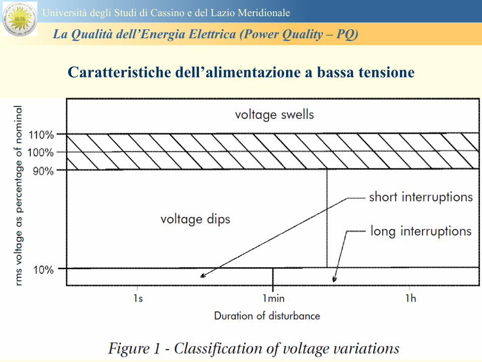
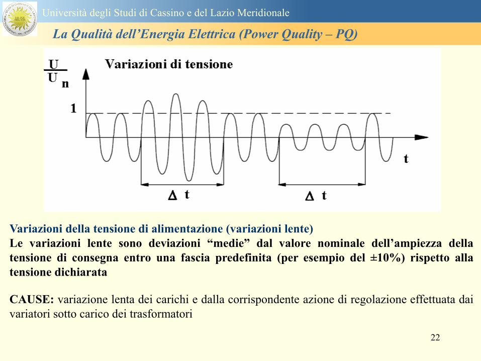
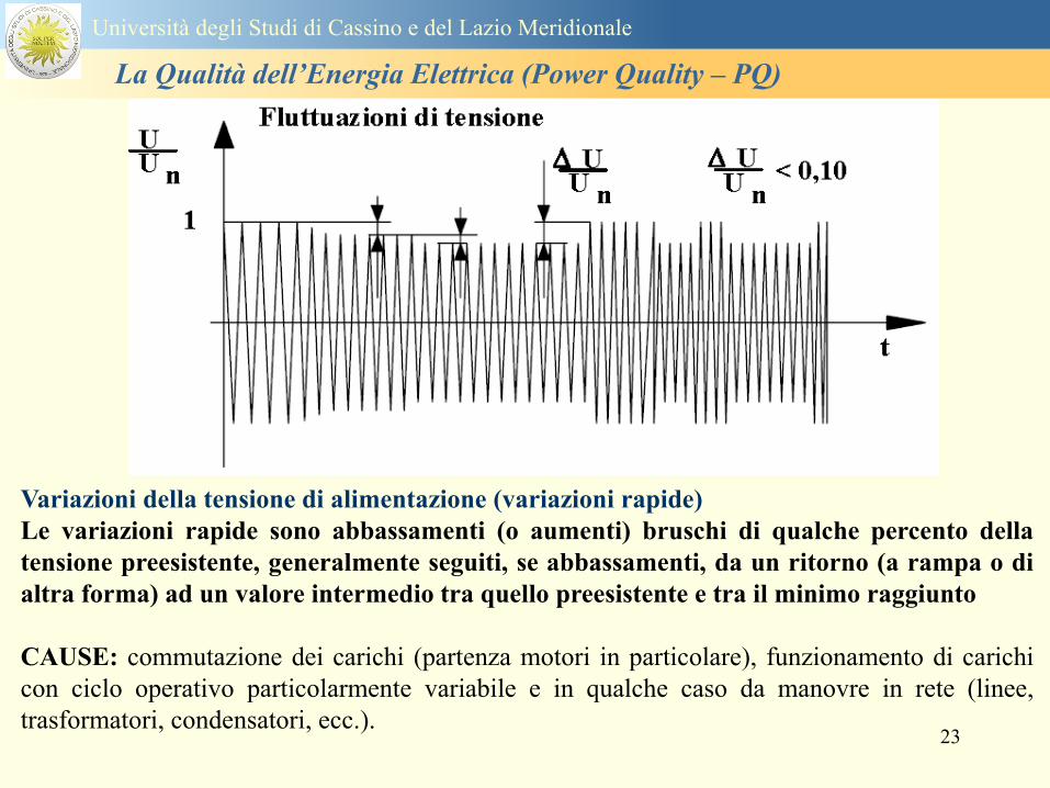
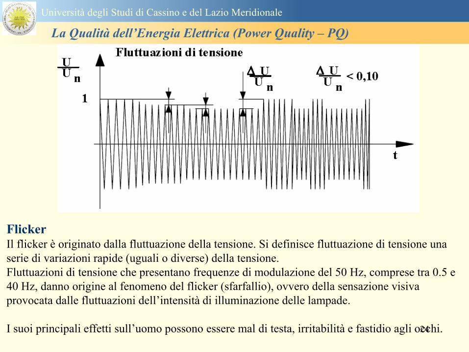
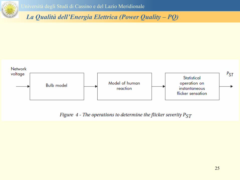
25
Universitagrave degli Studi di Cassino e del Lazio Meridionale
La Qualitagrave dellrsquoEnergia Elettrica (Power Quality ndash PQ)
26
La Qualitagrave dellrsquoEnergia Elettrica (Power Quality ndash PQ)
Universitagrave degli Studi di Cassino e del Lazio Meridionale
La Qualitagrave dellrsquoEnergia Elettrica (Power Quality ndash PQ)
27
Universitagrave degli Studi di Cassino e del Lazio Meridionale
La Qualitagrave dellrsquoEnergia Elettrica (Power Quality ndash PQ)
28
Universitagrave degli Studi di Cassino e del Lazio Meridionale
La Qualitagrave dellrsquoEnergia Elettrica (Power Quality ndash PQ)
29
Universitagrave degli Studi di Cassino e del Lazio Meridionale
La Qualitagrave dellrsquoEnergia Elettrica (Power Quality ndash PQ)
30
Universitagrave degli Studi di Cassino e del Lazio Meridionale
La Qualitagrave dellrsquoEnergia Elettrica (Power Quality ndash PQ)
31
Universitagrave degli Studi di Cassino e del Lazio Meridionale
La Qualitagrave dellrsquoEnergia Elettrica (Power Quality ndash PQ)
32
Buchi di tensione Riduzione temporanea della tensione in un punto della rete elettrica sotto una determinata
soglia Se durante un buco la tensione scende sotto una soglia di interruzione lrsquoevento egrave
considerato essere sia un buco che unrsquointerruzione
CAUSE I buchi di tensione sono generalmente dovuti a guasti che sopravvengono negli
impianti utilizzatori o nel sistema di distribuzione pubblico Possono dipendere anche variazioni
di carico lungo la linea
Universitagrave degli Studi di Cassino e del Lazio Meridionale
La Qualitagrave dellrsquoEnergia Elettrica (Power Quality ndash PQ)
33
Interruzioni della tensione di alimentazione Condizione in cui la tensione ad un terminale della rete egrave inferiore allrsquo1 della tensione
nominale per una durata fino a tre minuti (brevi) o maggiori di 3 minuti (lunghe)
Universitagrave degli Studi di Cassino e del Lazio Meridionale
La Qualitagrave dellrsquoEnergia Elettrica (Power Quality ndash PQ)
34
Sovratensioni temporanee alla frequenza di rete fra fasi e terra Le sovratensioni sono sopraelevazioni della tensione conseguenti a modificazioni dello
stato elettrico della rete elettrica
Universitagrave degli Studi di Cassino e del Lazio Meridionale
La Qualitagrave dellrsquoEnergia Elettrica (Power Quality ndash PQ)
35
Armoniche Le armoniche sono tensioni o correnti sinusoidali con frequenza pari ad un multiplo intero
(ordine) della frequenza fondamentale di funzionamento del sistema elettrico la cui
presenza determina una distorsione della forma drsquoonda della tensione di alimentazione
CAUSE In piccola parte dal sistema stesso (trasformatori etc) e per la maggior parte da
apparecchi utilizzatori carichi commutati elettronicamente raddrizzatori convertitori regolatori
in AC cicloconvertitori ecc carichi con caratteristiche non lineari apparecchiature a
saturazione magnetica lampade a scarica forni ad arco saldatrici ad arco trasformatori ecc
bull carichi inseriti e disinseriti da organi di manovra condensatori filtri e motori a induzione
Universitagrave degli Studi di Cassino e del Lazio Meridionale
La Qualitagrave dellrsquoEnergia Elettrica (Power Quality ndash PQ)
36
Armoniche di tensione e corrente ndash Problemi
Vi sono diversi ambiti causati dalle armoniche
bull problemi causati da armoniche di corrente
1048707 sovraccarico del neutro
1048707 aumento delle perdite nei trasformatori
1048707 interventi intempestivi degli interruttori automatici
1048707 aumento dellrsquoeffetto pelle
bull problemi causati da armoniche di tensione
1048707 deformazione della tensione
1048707 disturbi nella coppia dei motori ad induzione
1048707 rumore al passaggio per lo zero
bull problemi causati quando le armoniche di corrente raggiungono lrsquoalimentazione
Universitagrave degli Studi di Cassino e del Lazio Meridionale
La Qualitagrave dellrsquoEnergia Elettrica (Power Quality ndash PQ)
37
38
Universitagrave degli Studi di Cassino e del Lazio Meridionale
La Qualitagrave dellrsquoEnergia Elettrica (Power Quality ndash PQ)
39
Strumentazione ldquohand heldrdquo con display
Universitagrave degli Studi di Cassino e del Lazio Meridionale
La Qualitagrave dellrsquoEnergia Elettrica (Power Quality ndash PQ)
40
Strumentazione ldquohand heldrdquo con display
Universitagrave degli Studi di Cassino e del Lazio Meridionale
La Qualitagrave dellrsquoEnergia Elettrica (Power Quality ndash PQ)
41
Strumentazione da registrazione
Universitagrave degli Studi di Cassino e del Lazio Meridionale
La Qualitagrave dellrsquoEnergia Elettrica (Power Quality ndash PQ)
42
Schema di principio ndash 61000-4-30 copy IEC2008
The electrical quantity to be measured may be either directly accessible as is
generally the case in low-voltage systems or accessible via measurement
transducers
An instrument may include the whole measurement chain In this standard the
normative part does not consider the measurement transducers external to the
instrument and their associated uncertainty
Universitagrave degli Studi di Cassino e del Lazio Meridionale
La Qualitagrave dellrsquoEnergia Elettrica (Power Quality ndash PQ)
43
Universitagrave degli Studi di Cassino Corso di Fondamenti di Misure
La Qualitagrave dellrsquoEnergia Elettrica (Power Quality ndash PQ)
Classi dei metodi di misura - 61000-4-30 copy IEC2008
For each class measurement methods and appropriate performance requirements
are included
Sono definite tre classi A S e B
Class A
This class is used where precise measurements are necessary for example for contractual
applications that may require resolving disputes verifying compliance with standards etc
Any measurements of a parameter carried out with two different instruments complying with
the requirements of Class A when measuring the same signals will produce matching results
within the specified uncertainty for that parameter
Class S
This class is used for statistical applications such as surveys or power quality assessment
possibly with a limited subset of parameters Although it uses equivalent intervals of
measurement as class A the class S processing requirements are lower
Class B
This class is defined in order to avoid making many existing instruments designs obsolete
NOTE Class B methods are not recommended for new designs Readers are advised that Class B may be removed in a
future Edition of this standard
44
Classi dei metodi di misura - 61000-4-30 copy IEC2008
Measurement aggregation over time intervals
CLASS A
The basic measurement time interval for parameter magnitudes (supply voltage harmonics
interharmonics and unbalance) shall be a 10-cycle time interval for a 50 Hz power system
or 12-cycle time interval for a 60 Hz power system
The 1012-cycle measurement shall be re-synchronized at every RTC 10 min tick
The 1012-cycle values are then aggregated over 3 additional intervals
ndash 150180-cycle interval (150 cycles for 50 Hz nominal or 180 cycles for 60 Hz nominal)
ndash 10 min interval
ndash 2 h interval
CLASS S
Same time intervals as Class A
CLASS B
The manufacturer shall specify the number and duration of aggregation time intervals
Universitagrave degli Studi di Cassino e del Lazio Meridionale
La Qualitagrave dellrsquoEnergia Elettrica (Power Quality ndash PQ)
45
Universitagrave degli Studi di Cassino e del Lazio Meridionale
La Qualitagrave dellrsquoEnergia Elettrica (Power Quality ndash PQ)
46
Universitagrave degli Studi di Cassino e del Lazio Meridionale
La Qualitagrave dellrsquoEnergia Elettrica (Power Quality ndash PQ)
Class A
The 10-min aggregated value shall be tagged with the absolute time (for
example 01H1000) The time tag is the time at the conclusion of the 10-min
aggregation
The data for the 10-min time interval shall be aggregated from 1012-cycle time
intervals
Each 10-minute interval shall begin on a UTC 10-min tick The 10-min tick is
also used to re-synchronize the 1012-cycle intervals and the 150180-cycle
intervals
The final 1012-cycle interval(s) in a 10-min aggregation period will typically
overlap in time with the UTC 10-min clock tick Any overlapping 1012-cycle
interval (Overlap 1 in Figure 2) is included in the aggregation of the previous
10-min interval
47
Universitagrave degli Studi di Cassino e del Lazio Meridionale
La Qualitagrave dellrsquoEnergia Elettrica (Power Quality ndash PQ)
48
Universitagrave degli Studi di Cassino e del Lazio Meridionale
La Qualitagrave dellrsquoEnergia Elettrica (Power Quality ndash PQ)
49
Classi dei metodi di misura - 61000-4-30 copy IEC2008
Real time clock (RTC) uncertainty
Sono definite le specifiche per le 3 classi
Flagging concept
During a dip swell or interruption the measurement algorithm for other
parameters (for example frequency measurement) might produce an unreliable
value The flagging concept therefore avoids counting a single event more than
once in different parameters (for example counting a single dip as both a dip and a
frequency variation) and indicates that an aggregated value might be unreliable
Universitagrave degli Studi di Cassino e del Lazio Meridionale
La Qualitagrave dellrsquoEnergia Elettrica (Power Quality ndash PQ)
50
Classi dei metodi di misura - 61000-4-30 copy IEC2008
Power quality parameters - INDICES
Per ogni parametro viene suggerito il metodo di misura per le tre classi e
(soprattutto) le caratteristiche di precisione Per alcuni parametri rimanda a
specifiche norme (ad esempio Flicker e Armonicheinterarmoniche)
Esempio - Power frequency Class A
The frequency reading shall be obtained every 10 s As power frequency may not be exactly 50 Hz or 60
Hz within the 10 s time clock interval the number of cycles may not be an integer number The
fundamental frequency output is the ratio of the number of integral cycles counted during the 10 s time
clock interval divided by the cumulative duration of the integer cycles Before each assessment
harmonics and interharmonics shall be attenuated to minimize the effects of multiple zero crossings
The measurement time intervals shall be non-overlapping Individual cycles that overlap the 10 s time
clock are discarded Each 10 s interval shall begin on an absolute 10 s time clock with uncertainty as
defined in 46
Other techniques that provide equivalent results such as convolution are acceptable
Class S Same as class A
Class B The manufacturer shall specify the process used for frequency measurement
Universitagrave degli Studi di Cassino e del Lazio Meridionale
La Qualitagrave dellrsquoEnergia Elettrica (Power Quality ndash PQ)
51
Classi dei metodi di misura - 61000-4-30 copy IEC2008
Power quality parameters - INDICES
Per ogni parametro viene suggerito il metodo di misura per le tre classi e
(soprattutto) le caratteristiche di precisione Per alcuni parametri rimanda a
specifiche norme (ad esempio Flicker e Armonicheinterarmoniche)
Esempio - Power frequency
Measurement uncertainty and measuring range
ndash Class A
Under the conditions described in 61 the measurement uncertainty shall not exceed
plusmn10 mHz over the measuring ranges 425 Hz ~ 575 Hz 51 Hz ~ 69 Hz
ndash Class S
Under the conditions described in 61 the measurement uncertainty shall not exceed
plusmn50 mHz over the measuring ranges 425 Hz ~ 575 Hz 51 Hz ~ 69 Hz
ndash Class B
The manufacturer shall specify the uncertainty over the measuring ranges 425 Hz ~
575 Hz 51 Hz ~ 69 Hz
Universitagrave degli Studi di Cassino e del Lazio Meridionale
La Qualitagrave dellrsquoEnergia Elettrica (Power Quality ndash PQ)
52
Magnitude of the supply voltage
Measurement method
ndash Class A
The measurement shall be the rms value of the voltage magnitude over
a 10-cycle time interval for 50 Hz power system or 12-cycle time
interval for 60 Hz power system Every 1012-cycle interval shall be
contiguous and not overlapping with adjacent 1012-cycle intervals
except as shown as Overlap 1 in Figure 2
NOTE 1 This specific measurement method is used for quasi-stationary signals and is
not used for the detection and measurement of disturbances dips swells voltage
interruptions and transients
NOTE 2 The rms value includes by definition harmonics interharmonics mains
signalling etc
- Class S same as Class A
Universitagrave degli Studi di Cassino e del Lazio Meridionale
La Qualitagrave dellrsquoEnergia Elettrica (Power Quality ndash PQ)
53
Magnitude of the supply voltage
Measurement uncertainty and measuring range
ndash Class A
Under the conditions described in Clause 6 the measurement uncertainty
shall not exceed plusmn01 of Udin over the range of 10 ~ 150 of Udin
ndash Class S
Under the conditions described in Clause 6 the measurement uncertainty
shall not exceed plusmn05 of Udin over the range of 20 ~ 120 of Udin
Universitagrave degli Studi di Cassino e del Lazio Meridionale
La Qualitagrave dellrsquoEnergia Elettrica (Power Quality ndash PQ)
54
Supply voltage dips and swells
Measurement method
ndash Class A
The basic measurement Urms of a voltage dip and swell shall be the
Urms(frac12) on each measurement channel (see Clause 322)
The cycle duration for Urms(frac12) depends on the frequency The
frequency might be determined by the last non-flagged power frequency
measurement (see Clause 47 and Clause 51) or by any other method
that yields the uncertainty requirements of Clause 6
NOTE 1 The Urms(frac12) value includes by definition harmonics interharmonics mains
signalling voltage etc
NOTE 2 It is important to avoid loss of data when dips and swells occur in a rapid
sequence (for example three events in one second with up to one minute between
sequences may occur when a recloser operates into a sustained fault) If during a rapid
burst the dipswell event characteristics cannot be recorded then a count of events may
be useful
Universitagrave degli Studi di Cassino e del Lazio Meridionale
La Qualitagrave dellrsquoEnergia Elettrica (Power Quality ndash PQ)
55
Supply voltage dips and swells
Detection and evaluation of a voltage dip
Voltage dip detection
The dip threshold is a percentage of either Udin or the sliding voltage
reference Usr (see 525 544) The user shall declare the reference
voltage in use
NOTE ndash On single-phase systems a voltage dip begins when the Urms voltage falls
below the dip threshold and ends when the Urms voltage is equal to or above the dip
threshold plus the hysteresis voltage
ndash On polyphase systems a dip begins when the Urms voltage of one or more channels is
below the dip threshold and ends when the Urms voltage on all measured channels is
equal to or above the dip threshold plus the hysteresis voltage
The dip threshold and the hysteresis voltage are both set by the user according to the
use
Universitagrave degli Studi di Cassino e del Lazio Meridionale
La Qualitagrave dellrsquoEnergia Elettrica (Power Quality ndash PQ)
56
Calculation of a sliding reference voltage
The sliding reference voltage implementation is optional not mandatory
If a sliding reference is chosen for voltage dip or swell detection this
shall be calculated using a first-order filter with a 1-min time constant
This filter is given by
Usr(n) = 09967 times Usr(nndash1) + 00033 times U(1012)rms
where
Usr(n) is the present value of the sliding reference voltage
Usr(nndash1) is the previous value of the sliding reference voltage and
U(1012)rms is the most recent 1012-cycle rms value
When the measurement is started the initial value of the sliding reference voltage is set
to the declared input voltage The sliding reference voltage is updated every 1012-
cycles If a 1012-cycle value is flagged the sliding reference voltage is not updated
and the previous value is used
Universitagrave degli Studi di Cassino e del Lazio Meridionale
La Qualitagrave dellrsquoEnergia Elettrica (Power Quality ndash PQ)
57
Supply voltage dips and swells
Voltage dip evaluation
A voltage dip is characterized by a pair of data either residual voltage
(Ures) or depth and duration
ndash the residual voltage of a voltage dip is the lowest Urms(frac12) value
measured on any channel during the dip
ndash the depth is the difference between the reference voltage (either Udin
or Usr) and the residual voltage It is generally expressed in percentage
of the reference voltage
NOTE 1 During the dip it may be useful to also record the lowest Urms(frac12) on each
channel in addition to the residual voltage of the dip The duration spent below the dip
threshold on each channel may also be useful
Universitagrave degli Studi di Cassino e del Lazio Meridionale
La Qualitagrave dellrsquoEnergia Elettrica (Power Quality ndash PQ)
58
Supply voltage dips and swells
Voltage dip evaluation
NOTE 2 If voltage waveforms are recorded before during and after a
dip useful information about phase angle changes may be available in
the recorded data
The start time of a dip shall be time stamped with the time of the start of
the Urms of the channel that initiated the event and the end time of the
dip shall be the time stamped with the time of the end of the Urms that
ended the event as defined by the threshold plus the hysteresis
The duration of a voltage dip is the time difference between the start
time and the end time of the voltage dip
Universitagrave degli Studi di Cassino e del Lazio Meridionale
La Qualitagrave dellrsquoEnergia Elettrica (Power Quality ndash PQ)
59
Supply voltage dips and swells
Residual voltage and swell voltage magnitude measurement
uncertainty
ndash Class A
The measurement uncertainty shall not exceed plusmn02 of Udin
ndash Class S
The measurement uncertainty shall not exceed plusmn10 of Udin
Universitagrave degli Studi di Cassino e del Lazio Meridionale
La Qualitagrave dellrsquoEnergia Elettrica (Power Quality ndash PQ)
60
Schema di principio ndash 61000-4-7 copy IEC2002
Universitagrave degli Studi di Cassino e del Lazio Meridionale
La Qualitagrave dellrsquoEnergia Elettrica (Power Quality ndash PQ)
61
Universitagrave degli Studi di Cassino e del Lazio Meridionale
La Qualitagrave dellrsquoEnergia Elettrica (Power Quality ndash PQ)
62
Universitagrave degli Studi di Cassino e del Lazio Meridionale
La Qualitagrave dellrsquoEnergia Elettrica (Power Quality ndash PQ)
63
Inter-Armoniche Le inter-armoniche sono tensioni o correnti sinusoidali con frequenza diversa da un
multiplo intero della fondamentale la cui presenza determina una distorsione
(modulazione) della forma donda della tensione di alimentazione
CAUSE dai carichi che assorbono correnti inter-armoniche
- carichi commutati elettronicamente convertitori cascata subsincrona cicloconvertitori regolatori con
controllo a pacchetti di cicli ecc
- carichi con caratteristiche non lineari eo non stazionarie forni ad arco saldatrici ad arco ecc
Universitagrave degli Studi di Cassino e del Lazio Meridionale
La Qualitagrave dellrsquoEnergia Elettrica (Power Quality ndash PQ)
64
Universitagrave degli Studi di Cassino e del Lazio Meridionale
La Qualitagrave dellrsquoEnergia Elettrica (Power Quality ndash PQ)
Un porsquo di esempi e
consigli praticihellip
65
0V
50V
100V
150V
200V
250V
300V
350V
0ms 5ms 10ms 15ms 20ms
t
u
0A
1A
2A
3A
i
0V
50V
100V
150V
200V
250V
300V
350V
0ms 5ms 10ms 15ms 20ms
t
u
0A
1A
2A
3A
i
0V
50V
100V
150V
200V
250V
300V
350V
0ms 5ms 10ms 15ms 20ms
t
u
0A
1A
2A
3A
i
gleichgerichtete
Netzspannung
Kondensator-
spannung
gleichgerichteter
Netzstrom
The situation
today
bull Computed current and voltage profiles when a
230 V 58 W fluorescent lamp with an old-style
electronic ballast is driven on the phase wire of
a typical power distribution system
System voltage 230 V
System frequency 50 Hz
Source resistance 500 mW
Longitudinal induction 904 microH
System impedance 575 mW
Mean dc current 180 mA
Smoothing capacitance220 microF
66
And what about electronic ballasts that are rated over 25W
Introduce electronic power factor correction (PFC)
0V
20V
40V
60V
80V
100V
120V
140V
160V
180V
200V
220V
0deg 15deg 30deg 45deg
u
00A
03A
06A
09A
12A
i
67
Though todayrsquos ballasts are better if
rated gt25 W bull Only
the
small
ones
continu
e to
pollute
just like
PCs
TV sets
do
68
This leads to a number of
previously unknown effects bull 1 Deformed voltage curves
bull 2 Huge inrush current peaks
bull 3 Instrument dependent measured parameters
bull 4 Increased loading of phase conductors
bull 5 Loading and overloading of the neutral conductor
bull 6 Overheating and start-up problems of induction motors
bull 7 Additional stray losses in transformers
bull 8 Repercussions of generators upon the mains
bull 9 Influence of capacitors repercussions upon the mains
and four additional complications in TN-C systems
10 Stray currents in equipotential bonding system magnetic fields
11 Contamination of data streams by stray currents
12 Stray currents in the earthing system corrosion damage
13 Lightning currents in devices and equipment
69
1 Deformed voltage curves
bull in theory
-350V
-300V
-250V
-200V
-150V
-100V
-50V
0V
50V
100V
150V
200V
250V
300V
350V
0 5 10 15 20
t ms
u
System voltage profile when driving
a single-phase load comprising
twenty 58 W energy-saver lamps in
parallel on a typical 230 V power
system
70
and in practice
bull An actual
current profile
bull
bull and
bull a voltage profile
bull
bull recorded in a large storage
dispatch and administrative
building
71
at home or in industrial environments
bull
bull Television 40
W
bull 200 Vdiv 2
Adiv
bull 5 msdiv
Harmonic
spectrum
Frequency
converter
50 Adiv
Phase currents
I1=I2=I3=160 A
IN=295 A
5 msdiv
72
Every periodic waveform can be written
as the infinite sum of sinusoidal waves
-175
-150
-125
-100
-75
-50
-25
0
25
50
75
100
125
150
175
0 5 10 15 20
t ms
i
mA
itot
i1
Synthesis of a triangular current profile 100mA
Content fundamental I = 99 mA Isup2 = 9855 mAsup2
Sum of squares Isup2 = 9855 mAsup2
Root of sum = RMS value I = 99 mA
-175
-150
-125
-100
-75
-50
-25
0
25
50
75
100
125
150
175
0 5 10 15 20
t ms
i
mA
itot
i1
i3
Synthesis of a triangular current profile 100mA
Content fundamental I = 99 mA Isup2 = 9855 mAsup2
Cont 3 rd harmonic I = -11 mA Isup2 = 122 mAsup2
Sum of squares Isup2 = 9977 mAsup2
Root of sum = RMS value I = 100 mA
-175
-150
-125
-100
-75
-50
-25
0
25
50
75
100
125
150
175
0 5 10 15 20
t ms
i
mA
itot
i1
i3
i5
Synthesis of a triangular current profile 100mA
Content fundamental I = 99 mA Isup2 = 9855 mAsup2
Cont 3 rd harmonic I = -11 mA Isup2 = 122 mAsup2
Cont 5 th harmonic I = 4 mA Isup2 = 16 mAsup2
Sum of squares Isup2 = 9993 mAsup2
Root of sum = RMS value I = 100 mA
-175
-150
-125
-100
-75
-50
-25
0
25
50
75
100
125
150
175
0 5 10 15 20
t ms
i
mA
itot
i1
i3
i5
i7
Synthesis of a triangular current profile 100mA
Content fundamental I = 99 mA Isup2 = 9855 mAsup2
Cont 3 rd harmonic I = -11 mA Isup2 = 122 mAsup2
Cont 5 th harmonic I = 4 mA Isup2 = 16 mAsup2
Cont 7 th harmonic I = -2 mA Isup2 = 4 mAsup2
Sum of squares Isup2 = 9997 mAsup2
Root of sum = RMS value I = 100 mA
-175
-150
-125
-100
-75
-50
-25
0
25
50
75
100
125
150
175
0 5 10 15 20
t ms
i
mA
itot i1
i3 i5
i7 i9
Synthesis of a triangular current profile 100mA
Content fundamental I = 99 mA Isup2 = 9855 mAsup2
Cont 3 rd harmonic I = -11 mA Isup2 = 122 mAsup2
Cont 5 th harmonic I = 4 mA Isup2 = 16 mAsup2
Cont 7 th harmonic I = -2 mA Isup2 = 4 mAsup2
Cont 9 th harmonic I = 1 mA Isup2 = 2 mAsup2
Sum of squares Isup2 = 9998 mAsup2
Root of sum = RMS value I = 100 mA
-175
-150
-125
-100
-75
-50
-25
0
25
50
75
100
125
150
175
0 5 10 15 20
t ms
i
mA
itot i1
i3 i5
i7 i9
i11
Synthesis of a triangular current profile 100mA
Content fundamental I = 99 mA Isup2 = 9855 mAsup2
Cont 3 rd harmonic I = -11 mA Isup2 = 122 mAsup2
Cont 5 th harmonic I = 4 mA Isup2 = 16 mAsup2
Cont 7 th harmonic I = -2 mA Isup2 = 4 mAsup2
Cont 9 th harmonic I = 1 mA Isup2 = 2 mAsup2
Cont 11 th harmonic I = -1 mA Isup2 = 1 mAsup2
Sum of squares Isup2 = 9999 mAsup2
Root of sum = RMS value I = 100 mA
-175
-150
-125
-100
-75
-50
-25
0
25
50
75
100
125
150
175
0 5 10 15 20
t ms
i
mA
itot i1
i3 i5
i7 i9
i11 i13
Synthesis of a triangular current profile 100mA
Content fundamental I = 99 mA Isup2 = 9855 mAsup2
Cont 3 rd harmonic I = -11 mA Isup2 = 122 mAsup2
Cont 5 th harmonic I = 4 mA Isup2 = 16 mAsup2
Cont 7 th harmonic I = -2 mA Isup2 = 4 mAsup2
Cont 9 th harmonic I = 1 mA Isup2 = 2 mAsup2
Cont 11 th harmonic I = -1 mA Isup2 = 1 mAsup2
Cont 13 th harmonic I = 1 mA Isup2 = 0 mAsup2
Sum of squares Isup2 = 9999 mAsup2
Root of sum = RMS value I = 100 mA
-175
-150
-125
-100
-75
-50
-25
0
25
50
75
100
125
150
175
0 5 10 15 20
t ms
i
mA
itot i1
i3 i5
i7 i9
i11 i13
i15
Synthesis of a triangular current profile 100mA
Content fundamental I = 99 mA Isup2 = 9855 mAsup2
Cont 3 rd harmonic I = -11 mA Isup2 = 122 mAsup2
Cont 5 th harmonic I = 4 mA Isup2 = 16 mAsup2
Cont 7 th harmonic I = -2 mA Isup2 = 4 mAsup2
Cont 9 th harmonic I = 1 mA Isup2 = 2 mAsup2
Cont 11 th harmonic I = -1 mA Isup2 = 1 mAsup2
Cont 13 th harmonic I = 1 mA Isup2 = 0 mAsup2
Cont 15 th harmonic I = 0 mA Isup2 = 0 mAsup2
Sum of squares Isup2 = 10000 mAsup2
Root of sum = RMS value I = 100 mA
-175
-150
-125
-100
-75
-50
-25
0
25
50
75
100
125
150
175
0 5 10 15 20
t ms
i
mA
itot i1
i3 i5
i7 i9
i11 i13
i15 i17
Synthesis of a triangular current profile 100mA
Content fundamental I = 99 mA Isup2 = 9855 mAsup2
Cont 3 rd harmonic I = -11 mA Isup2 = 122 mAsup2
Cont 5 th harmonic I = 4 mA Isup2 = 16 mAsup2
Cont 7 th harmonic I = -2 mA Isup2 = 4 mAsup2
Cont 9 th harmonic I = 1 mA Isup2 = 2 mAsup2
Cont 11 th harmonic I = -1 mA Isup2 = 1 mAsup2
Cont 13 th harmonic I = 1 mA Isup2 = 0 mAsup2
Cont 15 th harmonic I = 0 mA Isup2 = 0 mAsup2
Cont 17 th harmonic I = 0 mA Isup2 = 0 mAsup2
Sum of squares Isup2 = 10000 mAsup2
Root of sum = RMS value I = 100 mA
73
whose frequencies called harmonics are
integer multiples of the fundamental frequency
-175
-150
-125
-100
-75
-50
-25
0
25
50
75
100
125
150
175
0 5 10 15 20
t ms
i
mA
itot
i1
Synthesis of a rectangular current profile 100mA
Content fundamental I = 90 mA Isup2 = 8106 mAsup2
Sum of squares Isup2 = 8106 mAsup2
Root of sum = RMS value I = 90 mA
-175
-150
-125
-100
-75
-50
-25
0
25
50
75
100
125
150
175
0 5 10 15 20
t ms
i
mA
itot
i1
i3
Synthesis of a rectangular current profile 100mA
Content fundamental I = 90 mA Isup2 = 8106 mAsup2
Cont 3 rd harmonic I = 30 mA Isup2 = 901 mAsup2
Sum of squares Isup2 = 9006 mAsup2
Root of sum = RMS value I = 95 mA
-175
-150
-125
-100
-75
-50
-25
0
25
50
75
100
125
150
175
0 5 10 15 20
t ms
i
mA
itot
i1
i3
i5
Synthesis of a rectangular current profile 100mA
Content fundamental I = 90 mA Isup2 = 8106 mAsup2
Cont 3 rd harmonic I = 30 mA Isup2 = 901 mAsup2
Cont 5 th harmonic I = 18 mA Isup2 = 324 mAsup2
Sum of squares Isup2 = 9331 mAsup2
Root of sum = RMS value I = 97 mA
-175
-150
-125
-100
-75
-50
-25
0
25
50
75
100
125
150
175
0 5 10 15 20
t ms
i
mA
itot
i1
i3
i5
i7
Synthesis of a rectangular current profile 100mA
Content fundamental I = 90 mA Isup2 = 8106 mAsup2
Cont 3 rd harmonic I = 30 mA Isup2 = 901 mAsup2
Cont 5 th harmonic I = 18 mA Isup2 = 324 mAsup2
Cont 7 th harmonic I = 13 mA Isup2 = 165 mAsup2
Sum of squares Isup2 = 9496 mAsup2
Root of sum = RMS value I = 97 mA
-175
-150
-125
-100
-75
-50
-25
0
25
50
75
100
125
150
175
0 5 10 15 20
t ms
i
mA
itot i1
i3 i5
i7 i9
Synthesis of a rectangular current profile 100mA
Content fundamental I = 90 mA Isup2 = 8106 mAsup2
Cont 3 rd harmonic I = 30 mA Isup2 = 901 mAsup2
Cont 5 th harmonic I = 18 mA Isup2 = 324 mAsup2
Cont 7 th harmonic I = 13 mA Isup2 = 165 mAsup2
Cont 9 th harmonic I = 10 mA Isup2 = 100 mAsup2
Sum of squares Isup2 = 9596 mAsup2
Root of sum = RMS value I = 98 mA
-175
-150
-125
-100
-75
-50
-25
0
25
50
75
100
125
150
175
0 5 10 15 20
t ms
i
mA
itot i1
i3 i5
i7 i9
i11
Synthesis of a rectangular current profile 100mA
Content fundamental I = 90 mA Isup2 = 8106 mAsup2
Cont 3 rd harmonic I = 30 mA Isup2 = 901 mAsup2
Cont 5 th harmonic I = 18 mA Isup2 = 324 mAsup2
Cont 7 th harmonic I = 13 mA Isup2 = 165 mAsup2
Cont 9 th harmonic I = 10 mA Isup2 = 100 mAsup2
Cont 11 th harmonic I = 8 mA Isup2 = 67 mAsup2
Sum of squares Isup2 = 9663 mAsup2
Root of sum = RMS value I = 98 mA
-175
-150
-125
-100
-75
-50
-25
0
25
50
75
100
125
150
175
0 5 10 15 20
t ms
i
mA
itot i1
i3 i5
i7 i9
i11 i13
Synthesis of a rectangular current profile 100mA
Content fundamental I = 90 mA Isup2 = 8106 mAsup2
Cont 3 rd harmonic I = 30 mA Isup2 = 901 mAsup2
Cont 5 th harmonic I = 18 mA Isup2 = 324 mAsup2
Cont 7 th harmonic I = 13 mA Isup2 = 165 mAsup2
Cont 9 th harmonic I = 10 mA Isup2 = 100 mAsup2
Cont 11 th harmonic I = 8 mA Isup2 = 67 mAsup2
Cont 13 th harmonic I = 7 mA Isup2 = 48 mAsup2
Sum of squares Isup2 = 9711 mAsup2
Root of sum = RMS value I = 99 mA
-175
-150
-125
-100
-75
-50
-25
0
25
50
75
100
125
150
175
0 5 10 15 20
t ms
i
mA
itot i1
i3 i5
i7 i9
i11 i13
i15
Synthesis of a rectangular current profile 100mA
Content fundamental I = 90 mA Isup2 = 8106 mAsup2
Cont 3 rd harmonic I = 30 mA Isup2 = 901 mAsup2
Cont 5 th harmonic I = 18 mA Isup2 = 324 mAsup2
Cont 7 th harmonic I = 13 mA Isup2 = 165 mAsup2
Cont 9 th harmonic I = 10 mA Isup2 = 100 mAsup2
Cont 11 th harmonic I = 8 mA Isup2 = 67 mAsup2
Cont 13 th harmonic I = 7 mA Isup2 = 48 mAsup2
Cont 15 th harmonic I = 6 mA Isup2 = 36 mAsup2
Sum of squares Isup2 = 9747 mAsup2
Root of sum = RMS value I = 99 mA
-175
-150
-125
-100
-75
-50
-25
0
25
50
75
100
125
150
175
0 5 10 15 20
t ms
i
mA
itot i1
i3 i5
i7 i9
i11 i13
i15 i17
Synthesis of a rectangular current profile 100mA
Content fundamental I = 90 mA Isup2 = 8106 mAsup2
Cont 3 rd harmonic I = 30 mA Isup2 = 901 mAsup2
Cont 5 th harmonic I = 18 mA Isup2 = 324 mAsup2
Cont 7 th harmonic I = 13 mA Isup2 = 165 mAsup2
Cont 9 th harmonic I = 10 mA Isup2 = 100 mAsup2
Cont 11 th harmonic I = 8 mA Isup2 = 67 mAsup2
Cont 13 th harmonic I = 7 mA Isup2 = 48 mAsup2
Cont 15 th harmonic I = 6 mA Isup2 = 36 mAsup2
Cont 17 th harmonic I = 5 mA Isup2 = 28 mAsup2
Sum of squares Isup2 = 9775 mAsup2
Root of sum = RMS value I = 99 mA
74
Even far better simulations are
available free of charge at
bull wwwpowerstandardscomMcEachern
75
-4A
-3A
-2A
-1A
0A
1A
2A
3A
4A
0ms 5ms 10ms 15ms 20ms
t
i
-4A
-3A
-2A
-1A
0A
1A
2A
3A
4A
0ms 5ms 10ms 15ms 20ms
t
i
Applying the Fourier
analysis to a real PC
current does not work
directly
bull
bull but it can be
modelled by a similar
triangular curve in
which not all of the
higher harmonics
have been included
Triangular current profile of
the same amplitude and a
pulse duty cycle of 17
Input current of a PC
with monitor
76
Analysis of the model triangular waveform
-400
-350
-300
-250
-200
-150
-100
-50
0
50
100
150
200
250
300
350
400
0 5 10 15 20
t ms
iI
itot(t) L1 [A] i1(t) L1 [A]
i3(t) L1 [A] i5(t) L1 [A]
i7(t) L1 [A] i9(t) L1 [A]
i11(t) L1 [A] i13(t) L1 [A]
i15(t) L1 [A] i17(t) L1 [A]
77
M3
Harmonics
Energy
(active
power)
L1
L2
L3
N
PE
Important
bull Harmonics are created within the loads
themselves and can flow ldquoupstreamrdquo to
contaminate the power system
78
-6A
-5A
-4A
-3A
-2A
-1A
0A
1A
2A
3A
4A
5A
6A
0ms 5ms 10ms 15ms 20ms
t
i
Squared values
Without
Fundamental 502 mA 251986 mAsup2 the fundamental
3rd harmonic -479 mA 229000 mAsup2 229000 mAsup2
5th harmonic 434 mA 188595 mAsup2 188595 mAsup2
7th harmonic -374 mA 139903 mAsup2 139903 mAsup2
9th harmonic 304 mA 92527 mAsup2 92527 mAsup2
11th harmonic -232 mA 53671 mAsup2 53671 mAsup2
13th harmonic 163 mA 26600 mAsup2 26600 mAsup2
15th harmonic -104 mA 10780 mAsup2 10780 mAsup2
17th harmonic 57 mA 3299 mAsup2 3299 mAsup2
Sum of the squares 996362 mAsup2 744377 mAsup2
Root thereof 998 mAeff THD = 863 mA
What actually is THD Example shown here triangular current
profile with an rms current of 1000 mA
and a pulse duty cycle of 17
THDr (root mean square) = 863mA1000mA = 86
THDf (fundamental) = 863mA502mA = 172
79
Effect on phase-to-neutral
and phase-to-phase voltages
bull Recorded
on June
30 2002
230 p
m
bull What
was the
matter
then
bull The
soccer
final
Germany
vs
Brazil
80
The triple-N harmonics drive
a circulating current in the
delta winding of a distribution
transformer
bull but the
bull voltage harmonics
propagate into the next
low-voltage power
distribution system
81 0V
50V
100V
150V
200V
250V
300V
350V
400V
450V
500V
550V
0 10 20 30 40 50
t ms
u
0A
10A
20A
30A
40A
50A
60A
70A
80A
90A
100A
110A
120A
130A
140A
150A
i
Switching on just as supply voltage passes through zero
0V
50V
100V
150V
200V
250V
300V
350V
400V
450V
500V
550V
0 10 20 30 40 50
t ms
u
0A
10A
20A
30A
40A
50A
60A
70A
80A
90A
100A
110A
120A
130A
140A
150A
i
Switching on just as supply voltage is at its peak
2 Huge inrush current peaks
ndash in theory
82
and in practice
bull Inrush current of a
compact energy-
saver lamp and its
effect on the system
voltage (recorded at
the Technical
University of
Budapest)
bull
83
enables us to infer what
happens when run by a
normal three-phase supply
The same fluorescent lamp
with a magnetic ballast
bull The behaviour measured
when connected to
a dc supply
bull
Behaviour of a 58 W fluorescent lamp connected to a dc
supply
0
20
40
60
80
100
120
140
160
180
200
0 200 400 600 800 1000 1200
i mA
u
V
Measurement
Behaviour of a 58 W fluorescent lamp connected to a dc
supply
0
20
40
60
80
100
120
140
160
180
200
0 200 400 600 800 1000 1200
i mA
u
V
MeasurementCalculation
-350
-300
-250
-200
-150
-100
-50
0
50
100
150
200
250
300
350
0 5 10 15 20
t ms
u
V
-10
-08
-06
-04
-02
00
02
04
06
08
10
i
A
Systems voltage
Current
-350
-300
-250
-200
-150
-100
-50
0
50
100
150
200
250
300
350
0 5 10 15 20
t ms
u
V
-10
-08
-06
-04
-02
00
02
04
06
08
10
i
A
Systems voltage
Lamp voltage
Current
84
Warning ldquoCompensationrdquo is not
always what you think it is
bull Distinguish
between
bull Reactive
power
compensatio
n
aka power
factor
correction
Remedial
measure
Parallel (or
sometimes series)
compensation
using capacitors
Filter circuits
tuned to the
individual harmonic
frequencies
Harmonic
compensation
85
5 (Over)loading the neutral conductor
bull Magnetic ballast Old-style electronic ballast
-25A
-20A
-15A
-10A
-05A
00A
05A
10A
15A
20A
25A
0 5 10 15 20
t ms i
i(t) N
-25A
-20A
-15A
-10A
-05A
00A
05A
10A
15A
20A
25A
0 5 10 15 20
t ms
i
i(t) N
-25A
-20A
-15A
-10A
-05A
00A
05A
10A
15A
20A
25A
0 5 10 15 20
t ms
i
i(t) L1 i(t) L2 i(t) L3
-25A
-20A
-15A
-10A
-05A
00A
05A
10A
15A
20A
25A
0 5 10 15 20
t ms
i
i(t) L1
i(t) L2
i(t) L3
86
Adding the 3rd
harmonics
in the
neutral
wire
-150-100-50
050
100150
0deg 30deg 60deg 90deg 120deg 150deg 180deg 210deg 240deg 270deg 300deg 330deg 360deg
L1
-150-100-50
050
100150
0deg 30deg 60deg 90deg 120deg 150deg 180deg 210deg 240deg 270deg 300deg 330deg 360deg
L2
-150-100-50
050
100150
0deg 30deg 60deg 90deg 120deg 150deg 180deg 210deg 240deg 270deg 300deg 330deg 360deg
L3
-450-400-350-300-250-200-150-100-50
050
100150200250300350400450
0deg 30deg 60deg 90deg 120deg 150deg 180deg 210deg 240deg 270deg 300deg 330deg 360deg
f
iicirc
N
Physics dictates
that at any
moment in time
the phase and
neutral currents
must sum to zero
87
Effect on a three-phase ac motor
appears almost identical
bull The same motor is being
driven
simultaneously in
these three modes
homopolar system
zero-sequence system
direct system
positive-sequence system
inverse system
negative-sequence system
88
The transformer
influences the load
89
but the load also effects
the transformer
Total transformer loss is
2
)()(
nom
nomCunomFeLossI
IPPP
While total transformer loss really is
2
)(
2
)(
2
)(
nomnom
nomad
nom
nomCu
nom
nomFeLossI
I
f
fP
I
IP
U
UPP
90
6 ldquosupplementaryrdquo additional losses
in transformers
can be calculated rapidly
using the following two
simple formulae 50
2
2
1
2
11
Nn
n
nqh
I
In
I
I
e
eK
50
1
2
1
1
50
1
2
Nn
n
nNn
n
nI
IIII
where
Oh well
perhaps a practical
example is clearer
1000 compact 11W
(15VA) energy-saver
lamps powered by a
15kVA transformer
uSC=4 Pa=01PCu
Harmonics of an Osram Dulux 11W
CFL and a serial impedance of
R =291Ω amp X L=113Ω
U U sup2 I L I Lsup2 P aP Cu
n V Vsup2 mA mAsup2
1 2302 529920 485 23523 56
3 83 689 371 13764 295
5 107 1145 203 4121 245
7 43 185 53 281 33
9 11 12 30 90 17
11 23 53 38 144 42
13 10 10 15 23 09
15 06 04 15 23 12
17 11 12 15 23 15
19 05 03 09 08 07
21 05 03 13 17 18
23 06 04 08 06 08
25 04 02 06 04 05
27 06 04 08 06 11
29 04 02 05 03 05
31 03 01 05 03 06
33 03 01 05 03 06
35 03 01 04 02 05
37 03 01 04 02 05
39 03 01 03 01 03
41 01 00 03 01 04
43 02 00 02 00 02
45 01 00 02 00 02
47 01 00 02 00 02
49 01 00 01 00 01
51 01 00 01 00 01
P aP Cu = 814814
etc
etc
91
Harmonics measurement on an
Osram Dulux 11W compact
fluorescent lamp
U U sup2 I L I Lsup2 P addP Cu
n V Vsup2 mA mAsup2
1 2327 541493 489 23912 37
3 06 04 391 15288 215
5 44 194 264 6970 273
7 23 53 200 4000 307
9 01 00 192 3686 467
11 01 00 166 2756 522
13 01 00 127 1613 427
15 01 00 110 1210 426
17 01 00 102 1040 471
19 01 00 87 757 428
21 01 00 77 593 409
23 01 00 73 533 441
25 01 00 61 372 364
27 01 00 49 240 274
29 01 00 42 176 232
31 01 00 36 130 195
33 01 00 30 90 153
35 01 00 33 109 209
37 01 00 31 96 206
39 01 00 25 63 149
41 01 00 25 63 164
43 01 00 25 63 181
45 01 00 19 36 114
47 01 00 18 32 112
49 01 00 19 36 136
51 01 00 16 26 104
P aP Cu = 7017
To some extent
the transformer
protects itself
bull Always remember to
consider it
bull If the influence of the
transformer upon the load
did not exist then the
influence of the load upon
the transformer would be
nearly 9 times as high
7017
etc
etc
92
Rule of thumb Select transformers 35
larger than specification by apparent
power would require
bull This suffices to err
on the safe side
even in the worst
case and can
hardly ever be
wrong since
maximum
efficiency always
lies between 25
and 50 of rated
load
Efficiency of a 1 MVA transformer plotted against loading
985
986
987
988
989
990
991
992
993
994
0 25 50 75 100 125
Relative load h
Design with max Cu loss and min Fe loss
Design with min Cu loss and max Fe loss
1 MVA oil transformer according to HD 428
93
Measured response of an 11 W
fluorescent lamp operated with a
magnetic ballast
94
We are
dealing with
a complex
problem
bull These
effects
are not
isolated
but are
mutuall
y inter-
depende
nt
Effects 2 3 and 5 can be demonstrated
on DKIrsquos display panel
95
A conventional approximately resistive-
inductive load
mA
N L1 L2 L3
Two conventional approximately
resistive-inductive loads Three conventional approximately
resistive-inductive loads
96
A modern electronic load
mA
N
Two modern electronic loads Three modern electronic loads
L1 L2 L3
97
Discoveries on a
refurbished
junction box
System voltage
(as trigger
signal)
Current in the
earthing
conductor
between the
consumer unit
and the
bonding
busbar
98
The TN-C system that was perfectly
adequate some years ago is unable to meet
present-day requirements
-6
-4
-2
0
2
4
6
0 5 10 15 20
t ms
i
A
-350
-300
-250
-200
-150
-100
-50
0
50
100
150
200
250
300
350
0 5 10 15 20
t ms
u
V
99
ldquoTHFrdquo
(third harmonic
filter) made in
Finland
In certain situations this affordable
filter can be of help
German
version ldquoTHXrdquo
100
0Ω
5 Ω
1 0 Ω
1 5 Ω
2 0 Ω
2 5 Ω
3 0 Ω
3 5 Ω
4 0 Ω
0Hz 50Hz 100Hz 150Hz 200Hz 250Hz 300Hz
f
Z
-90deg
-75deg
-60deg
-45deg
-30deg
-15deg
0deg
15deg
30deg
45deg
60deg
75deg
90deg
φ
Reactorreactance
Capacitorreactance
Parallelimpedace
Phase angle
Data and frequency response
of the filter
bull 1320 microF
bull 875
14 mW microH
101
The filter in use
bull In a nursery running sodium vapour lamps (500 kW)
In a typical office and administrative building
102
The EMC Transformer from Switzerland
7 The effects of stray magnetic fields
in TN-C systems
bull ldquoWhen we build transformers the first thing we focus on is complying with our customersrsquo
requirements and only then on complying with standards Why Because it is customer
needs and not standards that offer real scope for product innovationrdquo
103
8 In a TN-C system problems arise from data
streams and working currents mixing
bull Others who
have drawn
attention to
this source of
data
transmission
errors include
engineering
and insurance
companies experts
consultants and many
others besides
104
9 Increased corrosive damage
bull This (once) galvanized steel strip ndash the earth
electrode of a TN-C-S system ndash was located close
to the transformer station
Side facing
transformer
station
Side facing
transformer
station
Side facing away
from transformer
station
Side facing away
from transformer
station
105
bull WRONG RIGHT
Working currents have no place
in earthing systems and
protective conductors
106
10 Lightning currents
107
Which bridge to
cross which bridge to
burn
Sometimes you just donlsquot
believe what you see
This one will soon
look rather charred
IEC 60364-5-54
54343 If from any point of the installation the neutral and protective
functions are provided by separate conductors it is not permitted to
connect the neutral conductor to any other earthed part of the
installation
108
Well then the rest is no longer a
miracle
109
110
111
Another means of (over)loading the
neutral conductor
bull dc currents
Original ldquoFakerdquo
112
and their
effects U = 2285 V
I = 92 mA
P = 182 W
S = 209 VA
Q = 103 VAr
LF = 087
cos φ = 099
U = 2243 V
I = 126 A
P = 380 W
S = 2860 VA
Q = 2830 VAr
No-load current in a
toroidal-core
transformer
200 VA
-350-300
-250-200
-150-100
-500
50
100150
200250
300350
0 10 20 30 40
t ms
u
V
-12
-10
-8
-6
-4
-2
0
2
4
6
8
10
12
i
mA
Voltage
Current
No-load current in a toroidal-core
transformer 200 VA when
running a 1500 W
hairdryer at
half-power
in parallel
-350-300
-250-200
-150-100
-500
50
100150
200250
300350
0 5 10 15 20 25 30 35 40
t ms
u
V
-6
-5
-4
-3
-2
-1
0
1
2
3
4
5
6
i
A
Voltage
Current
113
The later models donlsquot do it any more
The EN 61000-3-2 has at least managed
to put an end to this approach
Domestic appliances Max 105 A of 2nd harmonic
114
An electrical engineering wonder
dc current generates ac voltage
115
Spicing things up with a pinch of HF
electronic halogen lamp transformers
116
Decorative HF reactors
117
Current and power loss as a function of voltage
00
02
04
06
08
10
12
14
16
18
0 40 80 120 160 200 240
U V
I
A
0
20
40
60
80
100
120
PV
W
I [A]
Pv [W]
Power loss capacitor voltage
and total voltage as a function of current
0
50
100
150
200
250
300
350
400
450
000 025 050 075 100 125 150
I A
U
V
0
5
10
15
20
25
30
35
40
45
50
PV
W
Utot [V] Eff
UR [V] Eff
Pv [W]
The passive
harmonic filter
made of readily
available
components
bull is both
reliable
118
and effective
bull befor
e
bull after
119
Half the solution has already been implemented
120
And if thatrsquos not enough
bull Passive filter circuits will do it
121
So what do we need to do
bull In low-voltage power distribution systems
Do not use cables in which the neutral or protective earth conductor has a
reduced cross-section
Use only 5-core cable Do not install TN-C- or TN-C-S systems
Be generous when dimensioning conductor cross-sections This helps to
reduce line voltage drops and thus reduces the effect of current distortions on
the voltage as well as lowering energy losses (see VDE 0298 Part 100)
Generously dimensioned conductors will have no problem coping with any
future increase in demand
Only use measuring instruments that display the true root mean square value
(TRMS meters)
In medium-voltage power distribution systems
Use a varied mix of distribution transformers with different vector groups
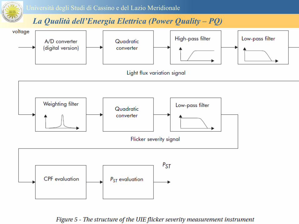
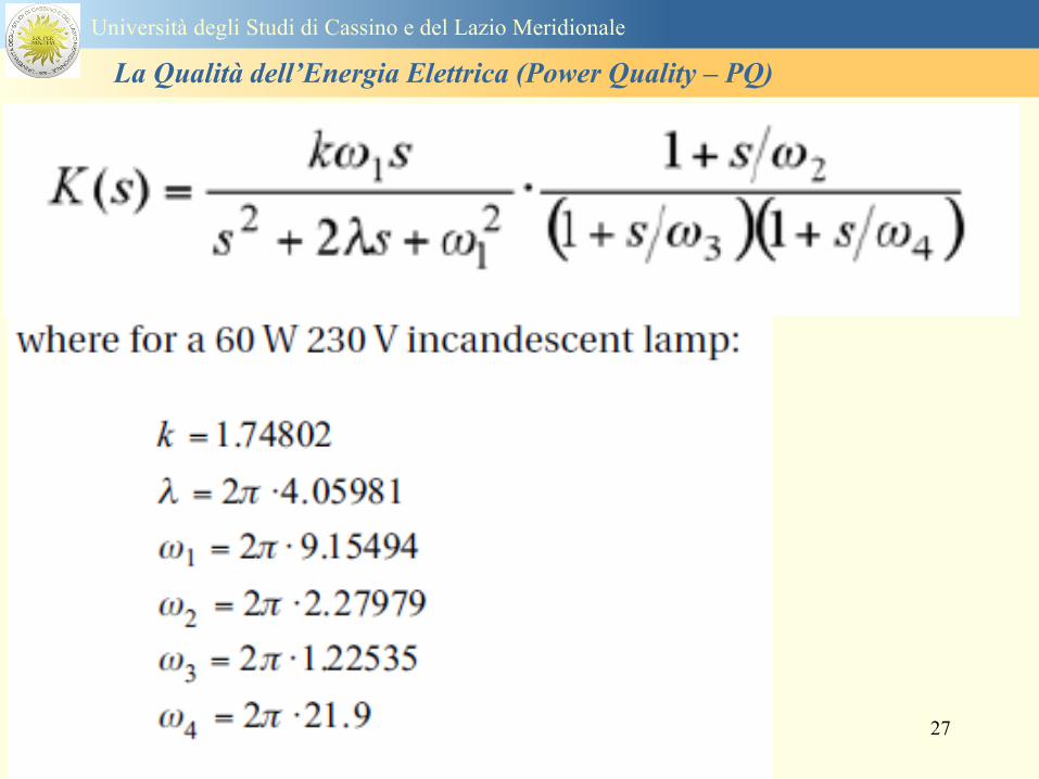
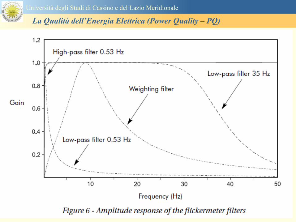
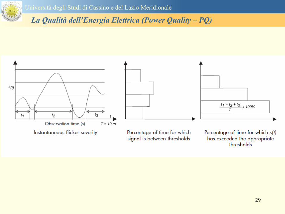
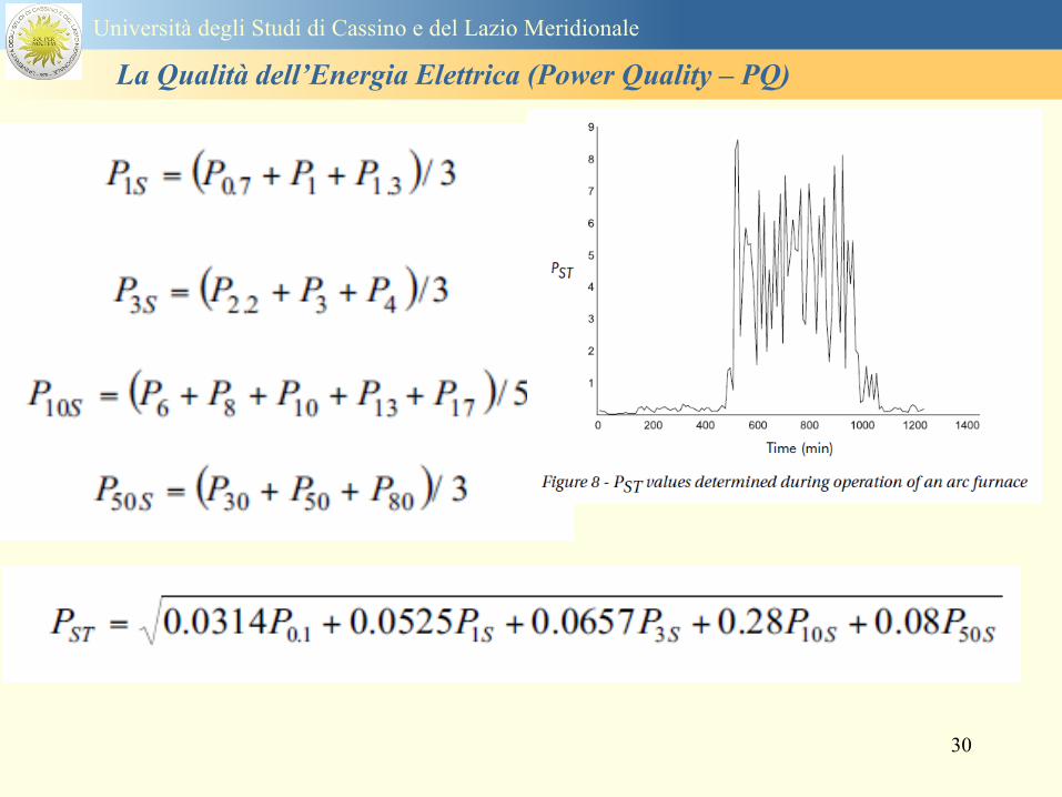
30
Universitagrave degli Studi di Cassino e del Lazio Meridionale
La Qualitagrave dellrsquoEnergia Elettrica (Power Quality ndash PQ)
31
Universitagrave degli Studi di Cassino e del Lazio Meridionale
La Qualitagrave dellrsquoEnergia Elettrica (Power Quality ndash PQ)
32
Buchi di tensione Riduzione temporanea della tensione in un punto della rete elettrica sotto una determinata
soglia Se durante un buco la tensione scende sotto una soglia di interruzione lrsquoevento egrave
considerato essere sia un buco che unrsquointerruzione
CAUSE I buchi di tensione sono generalmente dovuti a guasti che sopravvengono negli
impianti utilizzatori o nel sistema di distribuzione pubblico Possono dipendere anche variazioni
di carico lungo la linea
Universitagrave degli Studi di Cassino e del Lazio Meridionale
La Qualitagrave dellrsquoEnergia Elettrica (Power Quality ndash PQ)
33
Interruzioni della tensione di alimentazione Condizione in cui la tensione ad un terminale della rete egrave inferiore allrsquo1 della tensione
nominale per una durata fino a tre minuti (brevi) o maggiori di 3 minuti (lunghe)
Universitagrave degli Studi di Cassino e del Lazio Meridionale
La Qualitagrave dellrsquoEnergia Elettrica (Power Quality ndash PQ)
34
Sovratensioni temporanee alla frequenza di rete fra fasi e terra Le sovratensioni sono sopraelevazioni della tensione conseguenti a modificazioni dello
stato elettrico della rete elettrica
Universitagrave degli Studi di Cassino e del Lazio Meridionale
La Qualitagrave dellrsquoEnergia Elettrica (Power Quality ndash PQ)
35
Armoniche Le armoniche sono tensioni o correnti sinusoidali con frequenza pari ad un multiplo intero
(ordine) della frequenza fondamentale di funzionamento del sistema elettrico la cui
presenza determina una distorsione della forma drsquoonda della tensione di alimentazione
CAUSE In piccola parte dal sistema stesso (trasformatori etc) e per la maggior parte da
apparecchi utilizzatori carichi commutati elettronicamente raddrizzatori convertitori regolatori
in AC cicloconvertitori ecc carichi con caratteristiche non lineari apparecchiature a
saturazione magnetica lampade a scarica forni ad arco saldatrici ad arco trasformatori ecc
bull carichi inseriti e disinseriti da organi di manovra condensatori filtri e motori a induzione
Universitagrave degli Studi di Cassino e del Lazio Meridionale
La Qualitagrave dellrsquoEnergia Elettrica (Power Quality ndash PQ)
36
Armoniche di tensione e corrente ndash Problemi
Vi sono diversi ambiti causati dalle armoniche
bull problemi causati da armoniche di corrente
1048707 sovraccarico del neutro
1048707 aumento delle perdite nei trasformatori
1048707 interventi intempestivi degli interruttori automatici
1048707 aumento dellrsquoeffetto pelle
bull problemi causati da armoniche di tensione
1048707 deformazione della tensione
1048707 disturbi nella coppia dei motori ad induzione
1048707 rumore al passaggio per lo zero
bull problemi causati quando le armoniche di corrente raggiungono lrsquoalimentazione
Universitagrave degli Studi di Cassino e del Lazio Meridionale
La Qualitagrave dellrsquoEnergia Elettrica (Power Quality ndash PQ)
37
38
Universitagrave degli Studi di Cassino e del Lazio Meridionale
La Qualitagrave dellrsquoEnergia Elettrica (Power Quality ndash PQ)
39
Strumentazione ldquohand heldrdquo con display
Universitagrave degli Studi di Cassino e del Lazio Meridionale
La Qualitagrave dellrsquoEnergia Elettrica (Power Quality ndash PQ)
40
Strumentazione ldquohand heldrdquo con display
Universitagrave degli Studi di Cassino e del Lazio Meridionale
La Qualitagrave dellrsquoEnergia Elettrica (Power Quality ndash PQ)
41
Strumentazione da registrazione
Universitagrave degli Studi di Cassino e del Lazio Meridionale
La Qualitagrave dellrsquoEnergia Elettrica (Power Quality ndash PQ)
42
Schema di principio ndash 61000-4-30 copy IEC2008
The electrical quantity to be measured may be either directly accessible as is
generally the case in low-voltage systems or accessible via measurement
transducers
An instrument may include the whole measurement chain In this standard the
normative part does not consider the measurement transducers external to the
instrument and their associated uncertainty
Universitagrave degli Studi di Cassino e del Lazio Meridionale
La Qualitagrave dellrsquoEnergia Elettrica (Power Quality ndash PQ)
43
Universitagrave degli Studi di Cassino Corso di Fondamenti di Misure
La Qualitagrave dellrsquoEnergia Elettrica (Power Quality ndash PQ)
Classi dei metodi di misura - 61000-4-30 copy IEC2008
For each class measurement methods and appropriate performance requirements
are included
Sono definite tre classi A S e B
Class A
This class is used where precise measurements are necessary for example for contractual
applications that may require resolving disputes verifying compliance with standards etc
Any measurements of a parameter carried out with two different instruments complying with
the requirements of Class A when measuring the same signals will produce matching results
within the specified uncertainty for that parameter
Class S
This class is used for statistical applications such as surveys or power quality assessment
possibly with a limited subset of parameters Although it uses equivalent intervals of
measurement as class A the class S processing requirements are lower
Class B
This class is defined in order to avoid making many existing instruments designs obsolete
NOTE Class B methods are not recommended for new designs Readers are advised that Class B may be removed in a
future Edition of this standard
44
Classi dei metodi di misura - 61000-4-30 copy IEC2008
Measurement aggregation over time intervals
CLASS A
The basic measurement time interval for parameter magnitudes (supply voltage harmonics
interharmonics and unbalance) shall be a 10-cycle time interval for a 50 Hz power system
or 12-cycle time interval for a 60 Hz power system
The 1012-cycle measurement shall be re-synchronized at every RTC 10 min tick
The 1012-cycle values are then aggregated over 3 additional intervals
ndash 150180-cycle interval (150 cycles for 50 Hz nominal or 180 cycles for 60 Hz nominal)
ndash 10 min interval
ndash 2 h interval
CLASS S
Same time intervals as Class A
CLASS B
The manufacturer shall specify the number and duration of aggregation time intervals
Universitagrave degli Studi di Cassino e del Lazio Meridionale
La Qualitagrave dellrsquoEnergia Elettrica (Power Quality ndash PQ)
45
Universitagrave degli Studi di Cassino e del Lazio Meridionale
La Qualitagrave dellrsquoEnergia Elettrica (Power Quality ndash PQ)
46
Universitagrave degli Studi di Cassino e del Lazio Meridionale
La Qualitagrave dellrsquoEnergia Elettrica (Power Quality ndash PQ)
Class A
The 10-min aggregated value shall be tagged with the absolute time (for
example 01H1000) The time tag is the time at the conclusion of the 10-min
aggregation
The data for the 10-min time interval shall be aggregated from 1012-cycle time
intervals
Each 10-minute interval shall begin on a UTC 10-min tick The 10-min tick is
also used to re-synchronize the 1012-cycle intervals and the 150180-cycle
intervals
The final 1012-cycle interval(s) in a 10-min aggregation period will typically
overlap in time with the UTC 10-min clock tick Any overlapping 1012-cycle
interval (Overlap 1 in Figure 2) is included in the aggregation of the previous
10-min interval
47
Universitagrave degli Studi di Cassino e del Lazio Meridionale
La Qualitagrave dellrsquoEnergia Elettrica (Power Quality ndash PQ)
48
Universitagrave degli Studi di Cassino e del Lazio Meridionale
La Qualitagrave dellrsquoEnergia Elettrica (Power Quality ndash PQ)
49
Classi dei metodi di misura - 61000-4-30 copy IEC2008
Real time clock (RTC) uncertainty
Sono definite le specifiche per le 3 classi
Flagging concept
During a dip swell or interruption the measurement algorithm for other
parameters (for example frequency measurement) might produce an unreliable
value The flagging concept therefore avoids counting a single event more than
once in different parameters (for example counting a single dip as both a dip and a
frequency variation) and indicates that an aggregated value might be unreliable
Universitagrave degli Studi di Cassino e del Lazio Meridionale
La Qualitagrave dellrsquoEnergia Elettrica (Power Quality ndash PQ)
50
Classi dei metodi di misura - 61000-4-30 copy IEC2008
Power quality parameters - INDICES
Per ogni parametro viene suggerito il metodo di misura per le tre classi e
(soprattutto) le caratteristiche di precisione Per alcuni parametri rimanda a
specifiche norme (ad esempio Flicker e Armonicheinterarmoniche)
Esempio - Power frequency Class A
The frequency reading shall be obtained every 10 s As power frequency may not be exactly 50 Hz or 60
Hz within the 10 s time clock interval the number of cycles may not be an integer number The
fundamental frequency output is the ratio of the number of integral cycles counted during the 10 s time
clock interval divided by the cumulative duration of the integer cycles Before each assessment
harmonics and interharmonics shall be attenuated to minimize the effects of multiple zero crossings
The measurement time intervals shall be non-overlapping Individual cycles that overlap the 10 s time
clock are discarded Each 10 s interval shall begin on an absolute 10 s time clock with uncertainty as
defined in 46
Other techniques that provide equivalent results such as convolution are acceptable
Class S Same as class A
Class B The manufacturer shall specify the process used for frequency measurement
Universitagrave degli Studi di Cassino e del Lazio Meridionale
La Qualitagrave dellrsquoEnergia Elettrica (Power Quality ndash PQ)
51
Classi dei metodi di misura - 61000-4-30 copy IEC2008
Power quality parameters - INDICES
Per ogni parametro viene suggerito il metodo di misura per le tre classi e
(soprattutto) le caratteristiche di precisione Per alcuni parametri rimanda a
specifiche norme (ad esempio Flicker e Armonicheinterarmoniche)
Esempio - Power frequency
Measurement uncertainty and measuring range
ndash Class A
Under the conditions described in 61 the measurement uncertainty shall not exceed
plusmn10 mHz over the measuring ranges 425 Hz ~ 575 Hz 51 Hz ~ 69 Hz
ndash Class S
Under the conditions described in 61 the measurement uncertainty shall not exceed
plusmn50 mHz over the measuring ranges 425 Hz ~ 575 Hz 51 Hz ~ 69 Hz
ndash Class B
The manufacturer shall specify the uncertainty over the measuring ranges 425 Hz ~
575 Hz 51 Hz ~ 69 Hz
Universitagrave degli Studi di Cassino e del Lazio Meridionale
La Qualitagrave dellrsquoEnergia Elettrica (Power Quality ndash PQ)
52
Magnitude of the supply voltage
Measurement method
ndash Class A
The measurement shall be the rms value of the voltage magnitude over
a 10-cycle time interval for 50 Hz power system or 12-cycle time
interval for 60 Hz power system Every 1012-cycle interval shall be
contiguous and not overlapping with adjacent 1012-cycle intervals
except as shown as Overlap 1 in Figure 2
NOTE 1 This specific measurement method is used for quasi-stationary signals and is
not used for the detection and measurement of disturbances dips swells voltage
interruptions and transients
NOTE 2 The rms value includes by definition harmonics interharmonics mains
signalling etc
- Class S same as Class A
Universitagrave degli Studi di Cassino e del Lazio Meridionale
La Qualitagrave dellrsquoEnergia Elettrica (Power Quality ndash PQ)
53
Magnitude of the supply voltage
Measurement uncertainty and measuring range
ndash Class A
Under the conditions described in Clause 6 the measurement uncertainty
shall not exceed plusmn01 of Udin over the range of 10 ~ 150 of Udin
ndash Class S
Under the conditions described in Clause 6 the measurement uncertainty
shall not exceed plusmn05 of Udin over the range of 20 ~ 120 of Udin
Universitagrave degli Studi di Cassino e del Lazio Meridionale
La Qualitagrave dellrsquoEnergia Elettrica (Power Quality ndash PQ)
54
Supply voltage dips and swells
Measurement method
ndash Class A
The basic measurement Urms of a voltage dip and swell shall be the
Urms(frac12) on each measurement channel (see Clause 322)
The cycle duration for Urms(frac12) depends on the frequency The
frequency might be determined by the last non-flagged power frequency
measurement (see Clause 47 and Clause 51) or by any other method
that yields the uncertainty requirements of Clause 6
NOTE 1 The Urms(frac12) value includes by definition harmonics interharmonics mains
signalling voltage etc
NOTE 2 It is important to avoid loss of data when dips and swells occur in a rapid
sequence (for example three events in one second with up to one minute between
sequences may occur when a recloser operates into a sustained fault) If during a rapid
burst the dipswell event characteristics cannot be recorded then a count of events may
be useful
Universitagrave degli Studi di Cassino e del Lazio Meridionale
La Qualitagrave dellrsquoEnergia Elettrica (Power Quality ndash PQ)
55
Supply voltage dips and swells
Detection and evaluation of a voltage dip
Voltage dip detection
The dip threshold is a percentage of either Udin or the sliding voltage
reference Usr (see 525 544) The user shall declare the reference
voltage in use
NOTE ndash On single-phase systems a voltage dip begins when the Urms voltage falls
below the dip threshold and ends when the Urms voltage is equal to or above the dip
threshold plus the hysteresis voltage
ndash On polyphase systems a dip begins when the Urms voltage of one or more channels is
below the dip threshold and ends when the Urms voltage on all measured channels is
equal to or above the dip threshold plus the hysteresis voltage
The dip threshold and the hysteresis voltage are both set by the user according to the
use
Universitagrave degli Studi di Cassino e del Lazio Meridionale
La Qualitagrave dellrsquoEnergia Elettrica (Power Quality ndash PQ)
56
Calculation of a sliding reference voltage
The sliding reference voltage implementation is optional not mandatory
If a sliding reference is chosen for voltage dip or swell detection this
shall be calculated using a first-order filter with a 1-min time constant
This filter is given by
Usr(n) = 09967 times Usr(nndash1) + 00033 times U(1012)rms
where
Usr(n) is the present value of the sliding reference voltage
Usr(nndash1) is the previous value of the sliding reference voltage and
U(1012)rms is the most recent 1012-cycle rms value
When the measurement is started the initial value of the sliding reference voltage is set
to the declared input voltage The sliding reference voltage is updated every 1012-
cycles If a 1012-cycle value is flagged the sliding reference voltage is not updated
and the previous value is used
Universitagrave degli Studi di Cassino e del Lazio Meridionale
La Qualitagrave dellrsquoEnergia Elettrica (Power Quality ndash PQ)
57
Supply voltage dips and swells
Voltage dip evaluation
A voltage dip is characterized by a pair of data either residual voltage
(Ures) or depth and duration
ndash the residual voltage of a voltage dip is the lowest Urms(frac12) value
measured on any channel during the dip
ndash the depth is the difference between the reference voltage (either Udin
or Usr) and the residual voltage It is generally expressed in percentage
of the reference voltage
NOTE 1 During the dip it may be useful to also record the lowest Urms(frac12) on each
channel in addition to the residual voltage of the dip The duration spent below the dip
threshold on each channel may also be useful
Universitagrave degli Studi di Cassino e del Lazio Meridionale
La Qualitagrave dellrsquoEnergia Elettrica (Power Quality ndash PQ)
58
Supply voltage dips and swells
Voltage dip evaluation
NOTE 2 If voltage waveforms are recorded before during and after a
dip useful information about phase angle changes may be available in
the recorded data
The start time of a dip shall be time stamped with the time of the start of
the Urms of the channel that initiated the event and the end time of the
dip shall be the time stamped with the time of the end of the Urms that
ended the event as defined by the threshold plus the hysteresis
The duration of a voltage dip is the time difference between the start
time and the end time of the voltage dip
Universitagrave degli Studi di Cassino e del Lazio Meridionale
La Qualitagrave dellrsquoEnergia Elettrica (Power Quality ndash PQ)
59
Supply voltage dips and swells
Residual voltage and swell voltage magnitude measurement
uncertainty
ndash Class A
The measurement uncertainty shall not exceed plusmn02 of Udin
ndash Class S
The measurement uncertainty shall not exceed plusmn10 of Udin
Universitagrave degli Studi di Cassino e del Lazio Meridionale
La Qualitagrave dellrsquoEnergia Elettrica (Power Quality ndash PQ)
60
Schema di principio ndash 61000-4-7 copy IEC2002
Universitagrave degli Studi di Cassino e del Lazio Meridionale
La Qualitagrave dellrsquoEnergia Elettrica (Power Quality ndash PQ)
61
Universitagrave degli Studi di Cassino e del Lazio Meridionale
La Qualitagrave dellrsquoEnergia Elettrica (Power Quality ndash PQ)
62
Universitagrave degli Studi di Cassino e del Lazio Meridionale
La Qualitagrave dellrsquoEnergia Elettrica (Power Quality ndash PQ)
63
Inter-Armoniche Le inter-armoniche sono tensioni o correnti sinusoidali con frequenza diversa da un
multiplo intero della fondamentale la cui presenza determina una distorsione
(modulazione) della forma donda della tensione di alimentazione
CAUSE dai carichi che assorbono correnti inter-armoniche
- carichi commutati elettronicamente convertitori cascata subsincrona cicloconvertitori regolatori con
controllo a pacchetti di cicli ecc
- carichi con caratteristiche non lineari eo non stazionarie forni ad arco saldatrici ad arco ecc
Universitagrave degli Studi di Cassino e del Lazio Meridionale
La Qualitagrave dellrsquoEnergia Elettrica (Power Quality ndash PQ)
64
Universitagrave degli Studi di Cassino e del Lazio Meridionale
La Qualitagrave dellrsquoEnergia Elettrica (Power Quality ndash PQ)
Un porsquo di esempi e
consigli praticihellip
65
0V
50V
100V
150V
200V
250V
300V
350V
0ms 5ms 10ms 15ms 20ms
t
u
0A
1A
2A
3A
i
0V
50V
100V
150V
200V
250V
300V
350V
0ms 5ms 10ms 15ms 20ms
t
u
0A
1A
2A
3A
i
0V
50V
100V
150V
200V
250V
300V
350V
0ms 5ms 10ms 15ms 20ms
t
u
0A
1A
2A
3A
i
gleichgerichtete
Netzspannung
Kondensator-
spannung
gleichgerichteter
Netzstrom
The situation
today
bull Computed current and voltage profiles when a
230 V 58 W fluorescent lamp with an old-style
electronic ballast is driven on the phase wire of
a typical power distribution system
System voltage 230 V
System frequency 50 Hz
Source resistance 500 mW
Longitudinal induction 904 microH
System impedance 575 mW
Mean dc current 180 mA
Smoothing capacitance220 microF
66
And what about electronic ballasts that are rated over 25W
Introduce electronic power factor correction (PFC)
0V
20V
40V
60V
80V
100V
120V
140V
160V
180V
200V
220V
0deg 15deg 30deg 45deg
u
00A
03A
06A
09A
12A
i
67
Though todayrsquos ballasts are better if
rated gt25 W bull Only
the
small
ones
continu
e to
pollute
just like
PCs
TV sets
do
68
This leads to a number of
previously unknown effects bull 1 Deformed voltage curves
bull 2 Huge inrush current peaks
bull 3 Instrument dependent measured parameters
bull 4 Increased loading of phase conductors
bull 5 Loading and overloading of the neutral conductor
bull 6 Overheating and start-up problems of induction motors
bull 7 Additional stray losses in transformers
bull 8 Repercussions of generators upon the mains
bull 9 Influence of capacitors repercussions upon the mains
and four additional complications in TN-C systems
10 Stray currents in equipotential bonding system magnetic fields
11 Contamination of data streams by stray currents
12 Stray currents in the earthing system corrosion damage
13 Lightning currents in devices and equipment
69
1 Deformed voltage curves
bull in theory
-350V
-300V
-250V
-200V
-150V
-100V
-50V
0V
50V
100V
150V
200V
250V
300V
350V
0 5 10 15 20
t ms
u
System voltage profile when driving
a single-phase load comprising
twenty 58 W energy-saver lamps in
parallel on a typical 230 V power
system
70
and in practice
bull An actual
current profile
bull
bull and
bull a voltage profile
bull
bull recorded in a large storage
dispatch and administrative
building
71
at home or in industrial environments
bull
bull Television 40
W
bull 200 Vdiv 2
Adiv
bull 5 msdiv
Harmonic
spectrum
Frequency
converter
50 Adiv
Phase currents
I1=I2=I3=160 A
IN=295 A
5 msdiv
72
Every periodic waveform can be written
as the infinite sum of sinusoidal waves
-175
-150
-125
-100
-75
-50
-25
0
25
50
75
100
125
150
175
0 5 10 15 20
t ms
i
mA
itot
i1
Synthesis of a triangular current profile 100mA
Content fundamental I = 99 mA Isup2 = 9855 mAsup2
Sum of squares Isup2 = 9855 mAsup2
Root of sum = RMS value I = 99 mA
-175
-150
-125
-100
-75
-50
-25
0
25
50
75
100
125
150
175
0 5 10 15 20
t ms
i
mA
itot
i1
i3
Synthesis of a triangular current profile 100mA
Content fundamental I = 99 mA Isup2 = 9855 mAsup2
Cont 3 rd harmonic I = -11 mA Isup2 = 122 mAsup2
Sum of squares Isup2 = 9977 mAsup2
Root of sum = RMS value I = 100 mA
-175
-150
-125
-100
-75
-50
-25
0
25
50
75
100
125
150
175
0 5 10 15 20
t ms
i
mA
itot
i1
i3
i5
Synthesis of a triangular current profile 100mA
Content fundamental I = 99 mA Isup2 = 9855 mAsup2
Cont 3 rd harmonic I = -11 mA Isup2 = 122 mAsup2
Cont 5 th harmonic I = 4 mA Isup2 = 16 mAsup2
Sum of squares Isup2 = 9993 mAsup2
Root of sum = RMS value I = 100 mA
-175
-150
-125
-100
-75
-50
-25
0
25
50
75
100
125
150
175
0 5 10 15 20
t ms
i
mA
itot
i1
i3
i5
i7
Synthesis of a triangular current profile 100mA
Content fundamental I = 99 mA Isup2 = 9855 mAsup2
Cont 3 rd harmonic I = -11 mA Isup2 = 122 mAsup2
Cont 5 th harmonic I = 4 mA Isup2 = 16 mAsup2
Cont 7 th harmonic I = -2 mA Isup2 = 4 mAsup2
Sum of squares Isup2 = 9997 mAsup2
Root of sum = RMS value I = 100 mA
-175
-150
-125
-100
-75
-50
-25
0
25
50
75
100
125
150
175
0 5 10 15 20
t ms
i
mA
itot i1
i3 i5
i7 i9
Synthesis of a triangular current profile 100mA
Content fundamental I = 99 mA Isup2 = 9855 mAsup2
Cont 3 rd harmonic I = -11 mA Isup2 = 122 mAsup2
Cont 5 th harmonic I = 4 mA Isup2 = 16 mAsup2
Cont 7 th harmonic I = -2 mA Isup2 = 4 mAsup2
Cont 9 th harmonic I = 1 mA Isup2 = 2 mAsup2
Sum of squares Isup2 = 9998 mAsup2
Root of sum = RMS value I = 100 mA
-175
-150
-125
-100
-75
-50
-25
0
25
50
75
100
125
150
175
0 5 10 15 20
t ms
i
mA
itot i1
i3 i5
i7 i9
i11
Synthesis of a triangular current profile 100mA
Content fundamental I = 99 mA Isup2 = 9855 mAsup2
Cont 3 rd harmonic I = -11 mA Isup2 = 122 mAsup2
Cont 5 th harmonic I = 4 mA Isup2 = 16 mAsup2
Cont 7 th harmonic I = -2 mA Isup2 = 4 mAsup2
Cont 9 th harmonic I = 1 mA Isup2 = 2 mAsup2
Cont 11 th harmonic I = -1 mA Isup2 = 1 mAsup2
Sum of squares Isup2 = 9999 mAsup2
Root of sum = RMS value I = 100 mA
-175
-150
-125
-100
-75
-50
-25
0
25
50
75
100
125
150
175
0 5 10 15 20
t ms
i
mA
itot i1
i3 i5
i7 i9
i11 i13
Synthesis of a triangular current profile 100mA
Content fundamental I = 99 mA Isup2 = 9855 mAsup2
Cont 3 rd harmonic I = -11 mA Isup2 = 122 mAsup2
Cont 5 th harmonic I = 4 mA Isup2 = 16 mAsup2
Cont 7 th harmonic I = -2 mA Isup2 = 4 mAsup2
Cont 9 th harmonic I = 1 mA Isup2 = 2 mAsup2
Cont 11 th harmonic I = -1 mA Isup2 = 1 mAsup2
Cont 13 th harmonic I = 1 mA Isup2 = 0 mAsup2
Sum of squares Isup2 = 9999 mAsup2
Root of sum = RMS value I = 100 mA
-175
-150
-125
-100
-75
-50
-25
0
25
50
75
100
125
150
175
0 5 10 15 20
t ms
i
mA
itot i1
i3 i5
i7 i9
i11 i13
i15
Synthesis of a triangular current profile 100mA
Content fundamental I = 99 mA Isup2 = 9855 mAsup2
Cont 3 rd harmonic I = -11 mA Isup2 = 122 mAsup2
Cont 5 th harmonic I = 4 mA Isup2 = 16 mAsup2
Cont 7 th harmonic I = -2 mA Isup2 = 4 mAsup2
Cont 9 th harmonic I = 1 mA Isup2 = 2 mAsup2
Cont 11 th harmonic I = -1 mA Isup2 = 1 mAsup2
Cont 13 th harmonic I = 1 mA Isup2 = 0 mAsup2
Cont 15 th harmonic I = 0 mA Isup2 = 0 mAsup2
Sum of squares Isup2 = 10000 mAsup2
Root of sum = RMS value I = 100 mA
-175
-150
-125
-100
-75
-50
-25
0
25
50
75
100
125
150
175
0 5 10 15 20
t ms
i
mA
itot i1
i3 i5
i7 i9
i11 i13
i15 i17
Synthesis of a triangular current profile 100mA
Content fundamental I = 99 mA Isup2 = 9855 mAsup2
Cont 3 rd harmonic I = -11 mA Isup2 = 122 mAsup2
Cont 5 th harmonic I = 4 mA Isup2 = 16 mAsup2
Cont 7 th harmonic I = -2 mA Isup2 = 4 mAsup2
Cont 9 th harmonic I = 1 mA Isup2 = 2 mAsup2
Cont 11 th harmonic I = -1 mA Isup2 = 1 mAsup2
Cont 13 th harmonic I = 1 mA Isup2 = 0 mAsup2
Cont 15 th harmonic I = 0 mA Isup2 = 0 mAsup2
Cont 17 th harmonic I = 0 mA Isup2 = 0 mAsup2
Sum of squares Isup2 = 10000 mAsup2
Root of sum = RMS value I = 100 mA
73
whose frequencies called harmonics are
integer multiples of the fundamental frequency
-175
-150
-125
-100
-75
-50
-25
0
25
50
75
100
125
150
175
0 5 10 15 20
t ms
i
mA
itot
i1
Synthesis of a rectangular current profile 100mA
Content fundamental I = 90 mA Isup2 = 8106 mAsup2
Sum of squares Isup2 = 8106 mAsup2
Root of sum = RMS value I = 90 mA
-175
-150
-125
-100
-75
-50
-25
0
25
50
75
100
125
150
175
0 5 10 15 20
t ms
i
mA
itot
i1
i3
Synthesis of a rectangular current profile 100mA
Content fundamental I = 90 mA Isup2 = 8106 mAsup2
Cont 3 rd harmonic I = 30 mA Isup2 = 901 mAsup2
Sum of squares Isup2 = 9006 mAsup2
Root of sum = RMS value I = 95 mA
-175
-150
-125
-100
-75
-50
-25
0
25
50
75
100
125
150
175
0 5 10 15 20
t ms
i
mA
itot
i1
i3
i5
Synthesis of a rectangular current profile 100mA
Content fundamental I = 90 mA Isup2 = 8106 mAsup2
Cont 3 rd harmonic I = 30 mA Isup2 = 901 mAsup2
Cont 5 th harmonic I = 18 mA Isup2 = 324 mAsup2
Sum of squares Isup2 = 9331 mAsup2
Root of sum = RMS value I = 97 mA
-175
-150
-125
-100
-75
-50
-25
0
25
50
75
100
125
150
175
0 5 10 15 20
t ms
i
mA
itot
i1
i3
i5
i7
Synthesis of a rectangular current profile 100mA
Content fundamental I = 90 mA Isup2 = 8106 mAsup2
Cont 3 rd harmonic I = 30 mA Isup2 = 901 mAsup2
Cont 5 th harmonic I = 18 mA Isup2 = 324 mAsup2
Cont 7 th harmonic I = 13 mA Isup2 = 165 mAsup2
Sum of squares Isup2 = 9496 mAsup2
Root of sum = RMS value I = 97 mA
-175
-150
-125
-100
-75
-50
-25
0
25
50
75
100
125
150
175
0 5 10 15 20
t ms
i
mA
itot i1
i3 i5
i7 i9
Synthesis of a rectangular current profile 100mA
Content fundamental I = 90 mA Isup2 = 8106 mAsup2
Cont 3 rd harmonic I = 30 mA Isup2 = 901 mAsup2
Cont 5 th harmonic I = 18 mA Isup2 = 324 mAsup2
Cont 7 th harmonic I = 13 mA Isup2 = 165 mAsup2
Cont 9 th harmonic I = 10 mA Isup2 = 100 mAsup2
Sum of squares Isup2 = 9596 mAsup2
Root of sum = RMS value I = 98 mA
-175
-150
-125
-100
-75
-50
-25
0
25
50
75
100
125
150
175
0 5 10 15 20
t ms
i
mA
itot i1
i3 i5
i7 i9
i11
Synthesis of a rectangular current profile 100mA
Content fundamental I = 90 mA Isup2 = 8106 mAsup2
Cont 3 rd harmonic I = 30 mA Isup2 = 901 mAsup2
Cont 5 th harmonic I = 18 mA Isup2 = 324 mAsup2
Cont 7 th harmonic I = 13 mA Isup2 = 165 mAsup2
Cont 9 th harmonic I = 10 mA Isup2 = 100 mAsup2
Cont 11 th harmonic I = 8 mA Isup2 = 67 mAsup2
Sum of squares Isup2 = 9663 mAsup2
Root of sum = RMS value I = 98 mA
-175
-150
-125
-100
-75
-50
-25
0
25
50
75
100
125
150
175
0 5 10 15 20
t ms
i
mA
itot i1
i3 i5
i7 i9
i11 i13
Synthesis of a rectangular current profile 100mA
Content fundamental I = 90 mA Isup2 = 8106 mAsup2
Cont 3 rd harmonic I = 30 mA Isup2 = 901 mAsup2
Cont 5 th harmonic I = 18 mA Isup2 = 324 mAsup2
Cont 7 th harmonic I = 13 mA Isup2 = 165 mAsup2
Cont 9 th harmonic I = 10 mA Isup2 = 100 mAsup2
Cont 11 th harmonic I = 8 mA Isup2 = 67 mAsup2
Cont 13 th harmonic I = 7 mA Isup2 = 48 mAsup2
Sum of squares Isup2 = 9711 mAsup2
Root of sum = RMS value I = 99 mA
-175
-150
-125
-100
-75
-50
-25
0
25
50
75
100
125
150
175
0 5 10 15 20
t ms
i
mA
itot i1
i3 i5
i7 i9
i11 i13
i15
Synthesis of a rectangular current profile 100mA
Content fundamental I = 90 mA Isup2 = 8106 mAsup2
Cont 3 rd harmonic I = 30 mA Isup2 = 901 mAsup2
Cont 5 th harmonic I = 18 mA Isup2 = 324 mAsup2
Cont 7 th harmonic I = 13 mA Isup2 = 165 mAsup2
Cont 9 th harmonic I = 10 mA Isup2 = 100 mAsup2
Cont 11 th harmonic I = 8 mA Isup2 = 67 mAsup2
Cont 13 th harmonic I = 7 mA Isup2 = 48 mAsup2
Cont 15 th harmonic I = 6 mA Isup2 = 36 mAsup2
Sum of squares Isup2 = 9747 mAsup2
Root of sum = RMS value I = 99 mA
-175
-150
-125
-100
-75
-50
-25
0
25
50
75
100
125
150
175
0 5 10 15 20
t ms
i
mA
itot i1
i3 i5
i7 i9
i11 i13
i15 i17
Synthesis of a rectangular current profile 100mA
Content fundamental I = 90 mA Isup2 = 8106 mAsup2
Cont 3 rd harmonic I = 30 mA Isup2 = 901 mAsup2
Cont 5 th harmonic I = 18 mA Isup2 = 324 mAsup2
Cont 7 th harmonic I = 13 mA Isup2 = 165 mAsup2
Cont 9 th harmonic I = 10 mA Isup2 = 100 mAsup2
Cont 11 th harmonic I = 8 mA Isup2 = 67 mAsup2
Cont 13 th harmonic I = 7 mA Isup2 = 48 mAsup2
Cont 15 th harmonic I = 6 mA Isup2 = 36 mAsup2
Cont 17 th harmonic I = 5 mA Isup2 = 28 mAsup2
Sum of squares Isup2 = 9775 mAsup2
Root of sum = RMS value I = 99 mA
74
Even far better simulations are
available free of charge at
bull wwwpowerstandardscomMcEachern
75
-4A
-3A
-2A
-1A
0A
1A
2A
3A
4A
0ms 5ms 10ms 15ms 20ms
t
i
-4A
-3A
-2A
-1A
0A
1A
2A
3A
4A
0ms 5ms 10ms 15ms 20ms
t
i
Applying the Fourier
analysis to a real PC
current does not work
directly
bull
bull but it can be
modelled by a similar
triangular curve in
which not all of the
higher harmonics
have been included
Triangular current profile of
the same amplitude and a
pulse duty cycle of 17
Input current of a PC
with monitor
76
Analysis of the model triangular waveform
-400
-350
-300
-250
-200
-150
-100
-50
0
50
100
150
200
250
300
350
400
0 5 10 15 20
t ms
iI
itot(t) L1 [A] i1(t) L1 [A]
i3(t) L1 [A] i5(t) L1 [A]
i7(t) L1 [A] i9(t) L1 [A]
i11(t) L1 [A] i13(t) L1 [A]
i15(t) L1 [A] i17(t) L1 [A]
77
M3
Harmonics
Energy
(active
power)
L1
L2
L3
N
PE
Important
bull Harmonics are created within the loads
themselves and can flow ldquoupstreamrdquo to
contaminate the power system
78
-6A
-5A
-4A
-3A
-2A
-1A
0A
1A
2A
3A
4A
5A
6A
0ms 5ms 10ms 15ms 20ms
t
i
Squared values
Without
Fundamental 502 mA 251986 mAsup2 the fundamental
3rd harmonic -479 mA 229000 mAsup2 229000 mAsup2
5th harmonic 434 mA 188595 mAsup2 188595 mAsup2
7th harmonic -374 mA 139903 mAsup2 139903 mAsup2
9th harmonic 304 mA 92527 mAsup2 92527 mAsup2
11th harmonic -232 mA 53671 mAsup2 53671 mAsup2
13th harmonic 163 mA 26600 mAsup2 26600 mAsup2
15th harmonic -104 mA 10780 mAsup2 10780 mAsup2
17th harmonic 57 mA 3299 mAsup2 3299 mAsup2
Sum of the squares 996362 mAsup2 744377 mAsup2
Root thereof 998 mAeff THD = 863 mA
What actually is THD Example shown here triangular current
profile with an rms current of 1000 mA
and a pulse duty cycle of 17
THDr (root mean square) = 863mA1000mA = 86
THDf (fundamental) = 863mA502mA = 172
79
Effect on phase-to-neutral
and phase-to-phase voltages
bull Recorded
on June
30 2002
230 p
m
bull What
was the
matter
then
bull The
soccer
final
Germany
vs
Brazil
80
The triple-N harmonics drive
a circulating current in the
delta winding of a distribution
transformer
bull but the
bull voltage harmonics
propagate into the next
low-voltage power
distribution system
81 0V
50V
100V
150V
200V
250V
300V
350V
400V
450V
500V
550V
0 10 20 30 40 50
t ms
u
0A
10A
20A
30A
40A
50A
60A
70A
80A
90A
100A
110A
120A
130A
140A
150A
i
Switching on just as supply voltage passes through zero
0V
50V
100V
150V
200V
250V
300V
350V
400V
450V
500V
550V
0 10 20 30 40 50
t ms
u
0A
10A
20A
30A
40A
50A
60A
70A
80A
90A
100A
110A
120A
130A
140A
150A
i
Switching on just as supply voltage is at its peak
2 Huge inrush current peaks
ndash in theory
82
and in practice
bull Inrush current of a
compact energy-
saver lamp and its
effect on the system
voltage (recorded at
the Technical
University of
Budapest)
bull
83
enables us to infer what
happens when run by a
normal three-phase supply
The same fluorescent lamp
with a magnetic ballast
bull The behaviour measured
when connected to
a dc supply
bull
Behaviour of a 58 W fluorescent lamp connected to a dc
supply
0
20
40
60
80
100
120
140
160
180
200
0 200 400 600 800 1000 1200
i mA
u
V
Measurement
Behaviour of a 58 W fluorescent lamp connected to a dc
supply
0
20
40
60
80
100
120
140
160
180
200
0 200 400 600 800 1000 1200
i mA
u
V
MeasurementCalculation
-350
-300
-250
-200
-150
-100
-50
0
50
100
150
200
250
300
350
0 5 10 15 20
t ms
u
V
-10
-08
-06
-04
-02
00
02
04
06
08
10
i
A
Systems voltage
Current
-350
-300
-250
-200
-150
-100
-50
0
50
100
150
200
250
300
350
0 5 10 15 20
t ms
u
V
-10
-08
-06
-04
-02
00
02
04
06
08
10
i
A
Systems voltage
Lamp voltage
Current
84
Warning ldquoCompensationrdquo is not
always what you think it is
bull Distinguish
between
bull Reactive
power
compensatio
n
aka power
factor
correction
Remedial
measure
Parallel (or
sometimes series)
compensation
using capacitors
Filter circuits
tuned to the
individual harmonic
frequencies
Harmonic
compensation
85
5 (Over)loading the neutral conductor
bull Magnetic ballast Old-style electronic ballast
-25A
-20A
-15A
-10A
-05A
00A
05A
10A
15A
20A
25A
0 5 10 15 20
t ms i
i(t) N
-25A
-20A
-15A
-10A
-05A
00A
05A
10A
15A
20A
25A
0 5 10 15 20
t ms
i
i(t) N
-25A
-20A
-15A
-10A
-05A
00A
05A
10A
15A
20A
25A
0 5 10 15 20
t ms
i
i(t) L1 i(t) L2 i(t) L3
-25A
-20A
-15A
-10A
-05A
00A
05A
10A
15A
20A
25A
0 5 10 15 20
t ms
i
i(t) L1
i(t) L2
i(t) L3
86
Adding the 3rd
harmonics
in the
neutral
wire
-150-100-50
050
100150
0deg 30deg 60deg 90deg 120deg 150deg 180deg 210deg 240deg 270deg 300deg 330deg 360deg
L1
-150-100-50
050
100150
0deg 30deg 60deg 90deg 120deg 150deg 180deg 210deg 240deg 270deg 300deg 330deg 360deg
L2
-150-100-50
050
100150
0deg 30deg 60deg 90deg 120deg 150deg 180deg 210deg 240deg 270deg 300deg 330deg 360deg
L3
-450-400-350-300-250-200-150-100-50
050
100150200250300350400450
0deg 30deg 60deg 90deg 120deg 150deg 180deg 210deg 240deg 270deg 300deg 330deg 360deg
f
iicirc
N
Physics dictates
that at any
moment in time
the phase and
neutral currents
must sum to zero
87
Effect on a three-phase ac motor
appears almost identical
bull The same motor is being
driven
simultaneously in
these three modes
homopolar system
zero-sequence system
direct system
positive-sequence system
inverse system
negative-sequence system
88
The transformer
influences the load
89
but the load also effects
the transformer
Total transformer loss is
2
)()(
nom
nomCunomFeLossI
IPPP
While total transformer loss really is
2
)(
2
)(
2
)(
nomnom
nomad
nom
nomCu
nom
nomFeLossI
I
f
fP
I
IP
U
UPP
90
6 ldquosupplementaryrdquo additional losses
in transformers
can be calculated rapidly
using the following two
simple formulae 50
2
2
1
2
11
Nn
n
nqh
I
In
I
I
e
eK
50
1
2
1
1
50
1
2
Nn
n
nNn
n
nI
IIII
where
Oh well
perhaps a practical
example is clearer
1000 compact 11W
(15VA) energy-saver
lamps powered by a
15kVA transformer
uSC=4 Pa=01PCu
Harmonics of an Osram Dulux 11W
CFL and a serial impedance of
R =291Ω amp X L=113Ω
U U sup2 I L I Lsup2 P aP Cu
n V Vsup2 mA mAsup2
1 2302 529920 485 23523 56
3 83 689 371 13764 295
5 107 1145 203 4121 245
7 43 185 53 281 33
9 11 12 30 90 17
11 23 53 38 144 42
13 10 10 15 23 09
15 06 04 15 23 12
17 11 12 15 23 15
19 05 03 09 08 07
21 05 03 13 17 18
23 06 04 08 06 08
25 04 02 06 04 05
27 06 04 08 06 11
29 04 02 05 03 05
31 03 01 05 03 06
33 03 01 05 03 06
35 03 01 04 02 05
37 03 01 04 02 05
39 03 01 03 01 03
41 01 00 03 01 04
43 02 00 02 00 02
45 01 00 02 00 02
47 01 00 02 00 02
49 01 00 01 00 01
51 01 00 01 00 01
P aP Cu = 814814
etc
etc
91
Harmonics measurement on an
Osram Dulux 11W compact
fluorescent lamp
U U sup2 I L I Lsup2 P addP Cu
n V Vsup2 mA mAsup2
1 2327 541493 489 23912 37
3 06 04 391 15288 215
5 44 194 264 6970 273
7 23 53 200 4000 307
9 01 00 192 3686 467
11 01 00 166 2756 522
13 01 00 127 1613 427
15 01 00 110 1210 426
17 01 00 102 1040 471
19 01 00 87 757 428
21 01 00 77 593 409
23 01 00 73 533 441
25 01 00 61 372 364
27 01 00 49 240 274
29 01 00 42 176 232
31 01 00 36 130 195
33 01 00 30 90 153
35 01 00 33 109 209
37 01 00 31 96 206
39 01 00 25 63 149
41 01 00 25 63 164
43 01 00 25 63 181
45 01 00 19 36 114
47 01 00 18 32 112
49 01 00 19 36 136
51 01 00 16 26 104
P aP Cu = 7017
To some extent
the transformer
protects itself
bull Always remember to
consider it
bull If the influence of the
transformer upon the load
did not exist then the
influence of the load upon
the transformer would be
nearly 9 times as high
7017
etc
etc
92
Rule of thumb Select transformers 35
larger than specification by apparent
power would require
bull This suffices to err
on the safe side
even in the worst
case and can
hardly ever be
wrong since
maximum
efficiency always
lies between 25
and 50 of rated
load
Efficiency of a 1 MVA transformer plotted against loading
985
986
987
988
989
990
991
992
993
994
0 25 50 75 100 125
Relative load h
Design with max Cu loss and min Fe loss
Design with min Cu loss and max Fe loss
1 MVA oil transformer according to HD 428
93
Measured response of an 11 W
fluorescent lamp operated with a
magnetic ballast
94
We are
dealing with
a complex
problem
bull These
effects
are not
isolated
but are
mutuall
y inter-
depende
nt
Effects 2 3 and 5 can be demonstrated
on DKIrsquos display panel
95
A conventional approximately resistive-
inductive load
mA
N L1 L2 L3
Two conventional approximately
resistive-inductive loads Three conventional approximately
resistive-inductive loads
96
A modern electronic load
mA
N
Two modern electronic loads Three modern electronic loads
L1 L2 L3
97
Discoveries on a
refurbished
junction box
System voltage
(as trigger
signal)
Current in the
earthing
conductor
between the
consumer unit
and the
bonding
busbar
98
The TN-C system that was perfectly
adequate some years ago is unable to meet
present-day requirements
-6
-4
-2
0
2
4
6
0 5 10 15 20
t ms
i
A
-350
-300
-250
-200
-150
-100
-50
0
50
100
150
200
250
300
350
0 5 10 15 20
t ms
u
V
99
ldquoTHFrdquo
(third harmonic
filter) made in
Finland
In certain situations this affordable
filter can be of help
German
version ldquoTHXrdquo
100
0Ω
5 Ω
1 0 Ω
1 5 Ω
2 0 Ω
2 5 Ω
3 0 Ω
3 5 Ω
4 0 Ω
0Hz 50Hz 100Hz 150Hz 200Hz 250Hz 300Hz
f
Z
-90deg
-75deg
-60deg
-45deg
-30deg
-15deg
0deg
15deg
30deg
45deg
60deg
75deg
90deg
φ
Reactorreactance
Capacitorreactance
Parallelimpedace
Phase angle
Data and frequency response
of the filter
bull 1320 microF
bull 875
14 mW microH
101
The filter in use
bull In a nursery running sodium vapour lamps (500 kW)
In a typical office and administrative building
102
The EMC Transformer from Switzerland
7 The effects of stray magnetic fields
in TN-C systems
bull ldquoWhen we build transformers the first thing we focus on is complying with our customersrsquo
requirements and only then on complying with standards Why Because it is customer
needs and not standards that offer real scope for product innovationrdquo
103
8 In a TN-C system problems arise from data
streams and working currents mixing
bull Others who
have drawn
attention to
this source of
data
transmission
errors include
engineering
and insurance
companies experts
consultants and many
others besides
104
9 Increased corrosive damage
bull This (once) galvanized steel strip ndash the earth
electrode of a TN-C-S system ndash was located close
to the transformer station
Side facing
transformer
station
Side facing
transformer
station
Side facing away
from transformer
station
Side facing away
from transformer
station
105
bull WRONG RIGHT
Working currents have no place
in earthing systems and
protective conductors
106
10 Lightning currents
107
Which bridge to
cross which bridge to
burn
Sometimes you just donlsquot
believe what you see
This one will soon
look rather charred
IEC 60364-5-54
54343 If from any point of the installation the neutral and protective
functions are provided by separate conductors it is not permitted to
connect the neutral conductor to any other earthed part of the
installation
108
Well then the rest is no longer a
miracle
109
110
111
Another means of (over)loading the
neutral conductor
bull dc currents
Original ldquoFakerdquo
112
and their
effects U = 2285 V
I = 92 mA
P = 182 W
S = 209 VA
Q = 103 VAr
LF = 087
cos φ = 099
U = 2243 V
I = 126 A
P = 380 W
S = 2860 VA
Q = 2830 VAr
No-load current in a
toroidal-core
transformer
200 VA
-350-300
-250-200
-150-100
-500
50
100150
200250
300350
0 10 20 30 40
t ms
u
V
-12
-10
-8
-6
-4
-2
0
2
4
6
8
10
12
i
mA
Voltage
Current
No-load current in a toroidal-core
transformer 200 VA when
running a 1500 W
hairdryer at
half-power
in parallel
-350-300
-250-200
-150-100
-500
50
100150
200250
300350
0 5 10 15 20 25 30 35 40
t ms
u
V
-6
-5
-4
-3
-2
-1
0
1
2
3
4
5
6
i
A
Voltage
Current
113
The later models donlsquot do it any more
The EN 61000-3-2 has at least managed
to put an end to this approach
Domestic appliances Max 105 A of 2nd harmonic
114
An electrical engineering wonder
dc current generates ac voltage
115
Spicing things up with a pinch of HF
electronic halogen lamp transformers
116
Decorative HF reactors
117
Current and power loss as a function of voltage
00
02
04
06
08
10
12
14
16
18
0 40 80 120 160 200 240
U V
I
A
0
20
40
60
80
100
120
PV
W
I [A]
Pv [W]
Power loss capacitor voltage
and total voltage as a function of current
0
50
100
150
200
250
300
350
400
450
000 025 050 075 100 125 150
I A
U
V
0
5
10
15
20
25
30
35
40
45
50
PV
W
Utot [V] Eff
UR [V] Eff
Pv [W]
The passive
harmonic filter
made of readily
available
components
bull is both
reliable
118
and effective
bull befor
e
bull after
119
Half the solution has already been implemented
120
And if thatrsquos not enough
bull Passive filter circuits will do it
121
So what do we need to do
bull In low-voltage power distribution systems
Do not use cables in which the neutral or protective earth conductor has a
reduced cross-section
Use only 5-core cable Do not install TN-C- or TN-C-S systems
Be generous when dimensioning conductor cross-sections This helps to
reduce line voltage drops and thus reduces the effect of current distortions on
the voltage as well as lowering energy losses (see VDE 0298 Part 100)
Generously dimensioned conductors will have no problem coping with any
future increase in demand
Only use measuring instruments that display the true root mean square value
(TRMS meters)
In medium-voltage power distribution systems
Use a varied mix of distribution transformers with different vector groups
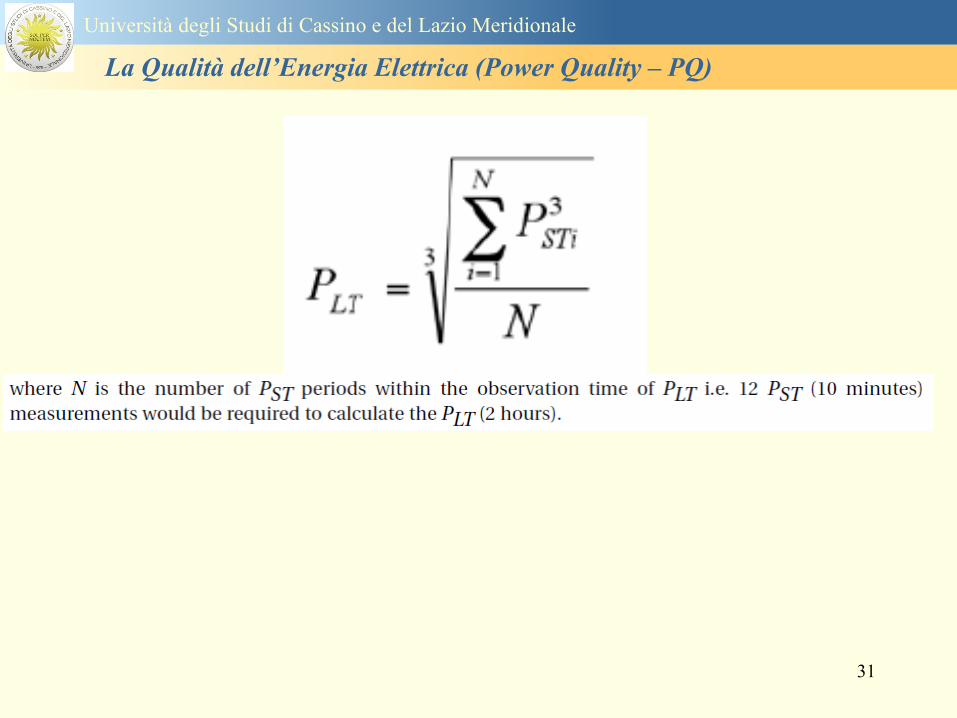
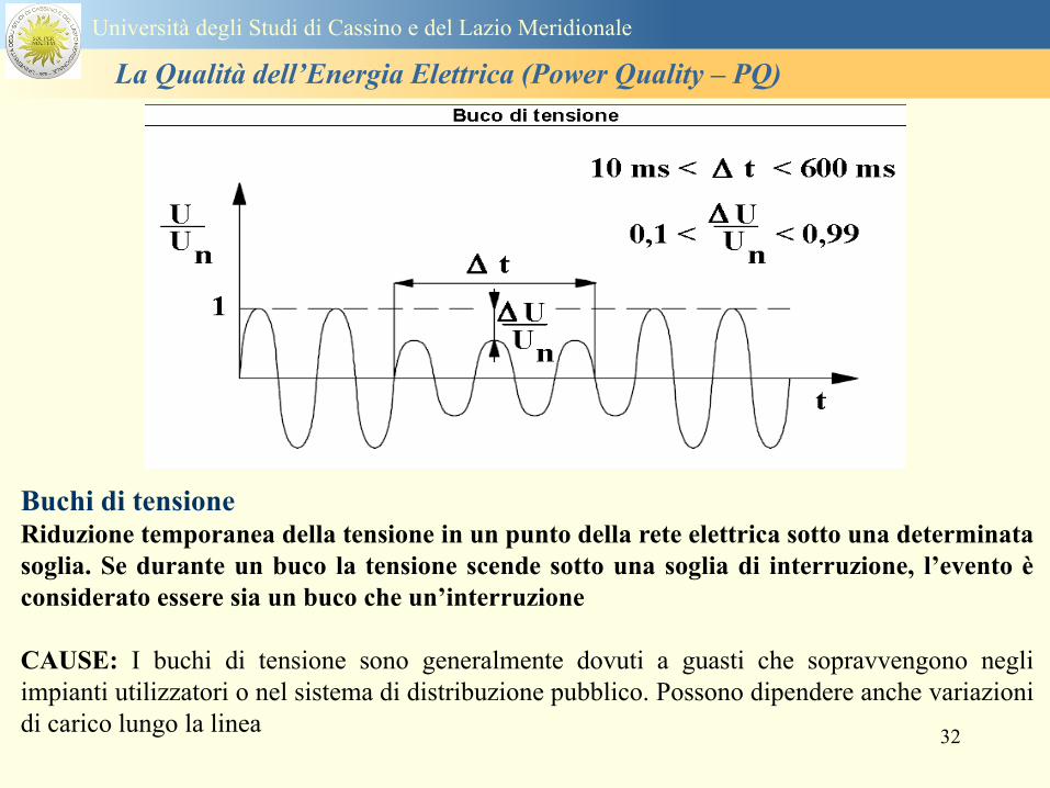
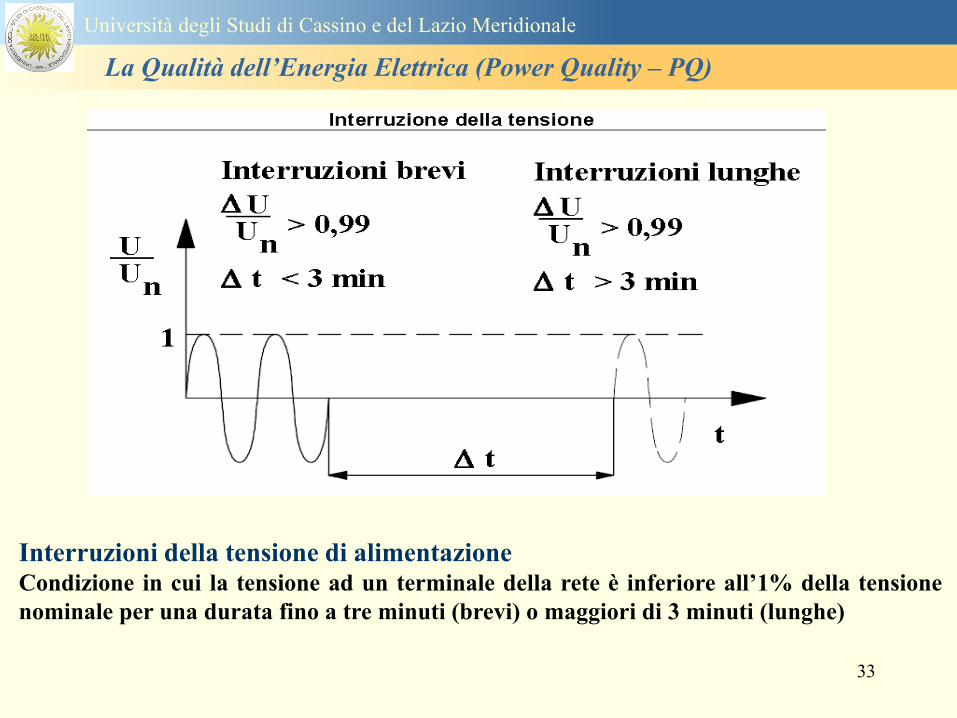
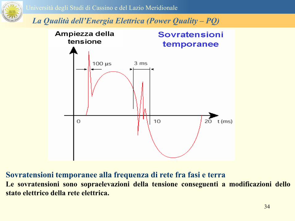
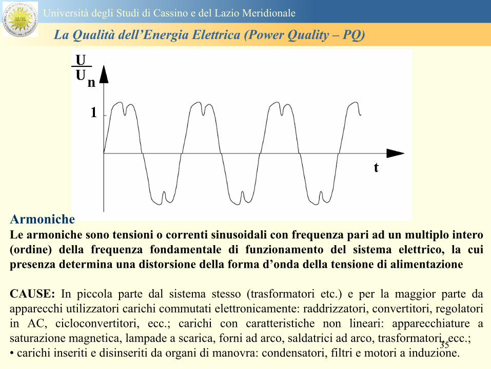
35
Armoniche Le armoniche sono tensioni o correnti sinusoidali con frequenza pari ad un multiplo intero
(ordine) della frequenza fondamentale di funzionamento del sistema elettrico la cui
presenza determina una distorsione della forma drsquoonda della tensione di alimentazione
CAUSE In piccola parte dal sistema stesso (trasformatori etc) e per la maggior parte da
apparecchi utilizzatori carichi commutati elettronicamente raddrizzatori convertitori regolatori
in AC cicloconvertitori ecc carichi con caratteristiche non lineari apparecchiature a
saturazione magnetica lampade a scarica forni ad arco saldatrici ad arco trasformatori ecc
bull carichi inseriti e disinseriti da organi di manovra condensatori filtri e motori a induzione
Universitagrave degli Studi di Cassino e del Lazio Meridionale
La Qualitagrave dellrsquoEnergia Elettrica (Power Quality ndash PQ)
36
Armoniche di tensione e corrente ndash Problemi
Vi sono diversi ambiti causati dalle armoniche
bull problemi causati da armoniche di corrente
1048707 sovraccarico del neutro
1048707 aumento delle perdite nei trasformatori
1048707 interventi intempestivi degli interruttori automatici
1048707 aumento dellrsquoeffetto pelle
bull problemi causati da armoniche di tensione
1048707 deformazione della tensione
1048707 disturbi nella coppia dei motori ad induzione
1048707 rumore al passaggio per lo zero
bull problemi causati quando le armoniche di corrente raggiungono lrsquoalimentazione
Universitagrave degli Studi di Cassino e del Lazio Meridionale
La Qualitagrave dellrsquoEnergia Elettrica (Power Quality ndash PQ)
37
38
Universitagrave degli Studi di Cassino e del Lazio Meridionale
La Qualitagrave dellrsquoEnergia Elettrica (Power Quality ndash PQ)
39
Strumentazione ldquohand heldrdquo con display
Universitagrave degli Studi di Cassino e del Lazio Meridionale
La Qualitagrave dellrsquoEnergia Elettrica (Power Quality ndash PQ)
40
Strumentazione ldquohand heldrdquo con display
Universitagrave degli Studi di Cassino e del Lazio Meridionale
La Qualitagrave dellrsquoEnergia Elettrica (Power Quality ndash PQ)
41
Strumentazione da registrazione
Universitagrave degli Studi di Cassino e del Lazio Meridionale
La Qualitagrave dellrsquoEnergia Elettrica (Power Quality ndash PQ)
42
Schema di principio ndash 61000-4-30 copy IEC2008
The electrical quantity to be measured may be either directly accessible as is
generally the case in low-voltage systems or accessible via measurement
transducers
An instrument may include the whole measurement chain In this standard the
normative part does not consider the measurement transducers external to the
instrument and their associated uncertainty
Universitagrave degli Studi di Cassino e del Lazio Meridionale
La Qualitagrave dellrsquoEnergia Elettrica (Power Quality ndash PQ)
43
Universitagrave degli Studi di Cassino Corso di Fondamenti di Misure
La Qualitagrave dellrsquoEnergia Elettrica (Power Quality ndash PQ)
Classi dei metodi di misura - 61000-4-30 copy IEC2008
For each class measurement methods and appropriate performance requirements
are included
Sono definite tre classi A S e B
Class A
This class is used where precise measurements are necessary for example for contractual
applications that may require resolving disputes verifying compliance with standards etc
Any measurements of a parameter carried out with two different instruments complying with
the requirements of Class A when measuring the same signals will produce matching results
within the specified uncertainty for that parameter
Class S
This class is used for statistical applications such as surveys or power quality assessment
possibly with a limited subset of parameters Although it uses equivalent intervals of
measurement as class A the class S processing requirements are lower
Class B
This class is defined in order to avoid making many existing instruments designs obsolete
NOTE Class B methods are not recommended for new designs Readers are advised that Class B may be removed in a
future Edition of this standard
44
Classi dei metodi di misura - 61000-4-30 copy IEC2008
Measurement aggregation over time intervals
CLASS A
The basic measurement time interval for parameter magnitudes (supply voltage harmonics
interharmonics and unbalance) shall be a 10-cycle time interval for a 50 Hz power system
or 12-cycle time interval for a 60 Hz power system
The 1012-cycle measurement shall be re-synchronized at every RTC 10 min tick
The 1012-cycle values are then aggregated over 3 additional intervals
ndash 150180-cycle interval (150 cycles for 50 Hz nominal or 180 cycles for 60 Hz nominal)
ndash 10 min interval
ndash 2 h interval
CLASS S
Same time intervals as Class A
CLASS B
The manufacturer shall specify the number and duration of aggregation time intervals
Universitagrave degli Studi di Cassino e del Lazio Meridionale
La Qualitagrave dellrsquoEnergia Elettrica (Power Quality ndash PQ)
45
Universitagrave degli Studi di Cassino e del Lazio Meridionale
La Qualitagrave dellrsquoEnergia Elettrica (Power Quality ndash PQ)
46
Universitagrave degli Studi di Cassino e del Lazio Meridionale
La Qualitagrave dellrsquoEnergia Elettrica (Power Quality ndash PQ)
Class A
The 10-min aggregated value shall be tagged with the absolute time (for
example 01H1000) The time tag is the time at the conclusion of the 10-min
aggregation
The data for the 10-min time interval shall be aggregated from 1012-cycle time
intervals
Each 10-minute interval shall begin on a UTC 10-min tick The 10-min tick is
also used to re-synchronize the 1012-cycle intervals and the 150180-cycle
intervals
The final 1012-cycle interval(s) in a 10-min aggregation period will typically
overlap in time with the UTC 10-min clock tick Any overlapping 1012-cycle
interval (Overlap 1 in Figure 2) is included in the aggregation of the previous
10-min interval
47
Universitagrave degli Studi di Cassino e del Lazio Meridionale
La Qualitagrave dellrsquoEnergia Elettrica (Power Quality ndash PQ)
48
Universitagrave degli Studi di Cassino e del Lazio Meridionale
La Qualitagrave dellrsquoEnergia Elettrica (Power Quality ndash PQ)
49
Classi dei metodi di misura - 61000-4-30 copy IEC2008
Real time clock (RTC) uncertainty
Sono definite le specifiche per le 3 classi
Flagging concept
During a dip swell or interruption the measurement algorithm for other
parameters (for example frequency measurement) might produce an unreliable
value The flagging concept therefore avoids counting a single event more than
once in different parameters (for example counting a single dip as both a dip and a
frequency variation) and indicates that an aggregated value might be unreliable
Universitagrave degli Studi di Cassino e del Lazio Meridionale
La Qualitagrave dellrsquoEnergia Elettrica (Power Quality ndash PQ)
50
Classi dei metodi di misura - 61000-4-30 copy IEC2008
Power quality parameters - INDICES
Per ogni parametro viene suggerito il metodo di misura per le tre classi e
(soprattutto) le caratteristiche di precisione Per alcuni parametri rimanda a
specifiche norme (ad esempio Flicker e Armonicheinterarmoniche)
Esempio - Power frequency Class A
The frequency reading shall be obtained every 10 s As power frequency may not be exactly 50 Hz or 60
Hz within the 10 s time clock interval the number of cycles may not be an integer number The
fundamental frequency output is the ratio of the number of integral cycles counted during the 10 s time
clock interval divided by the cumulative duration of the integer cycles Before each assessment
harmonics and interharmonics shall be attenuated to minimize the effects of multiple zero crossings
The measurement time intervals shall be non-overlapping Individual cycles that overlap the 10 s time
clock are discarded Each 10 s interval shall begin on an absolute 10 s time clock with uncertainty as
defined in 46
Other techniques that provide equivalent results such as convolution are acceptable
Class S Same as class A
Class B The manufacturer shall specify the process used for frequency measurement
Universitagrave degli Studi di Cassino e del Lazio Meridionale
La Qualitagrave dellrsquoEnergia Elettrica (Power Quality ndash PQ)
51
Classi dei metodi di misura - 61000-4-30 copy IEC2008
Power quality parameters - INDICES
Per ogni parametro viene suggerito il metodo di misura per le tre classi e
(soprattutto) le caratteristiche di precisione Per alcuni parametri rimanda a
specifiche norme (ad esempio Flicker e Armonicheinterarmoniche)
Esempio - Power frequency
Measurement uncertainty and measuring range
ndash Class A
Under the conditions described in 61 the measurement uncertainty shall not exceed
plusmn10 mHz over the measuring ranges 425 Hz ~ 575 Hz 51 Hz ~ 69 Hz
ndash Class S
Under the conditions described in 61 the measurement uncertainty shall not exceed
plusmn50 mHz over the measuring ranges 425 Hz ~ 575 Hz 51 Hz ~ 69 Hz
ndash Class B
The manufacturer shall specify the uncertainty over the measuring ranges 425 Hz ~
575 Hz 51 Hz ~ 69 Hz
Universitagrave degli Studi di Cassino e del Lazio Meridionale
La Qualitagrave dellrsquoEnergia Elettrica (Power Quality ndash PQ)
52
Magnitude of the supply voltage
Measurement method
ndash Class A
The measurement shall be the rms value of the voltage magnitude over
a 10-cycle time interval for 50 Hz power system or 12-cycle time
interval for 60 Hz power system Every 1012-cycle interval shall be
contiguous and not overlapping with adjacent 1012-cycle intervals
except as shown as Overlap 1 in Figure 2
NOTE 1 This specific measurement method is used for quasi-stationary signals and is
not used for the detection and measurement of disturbances dips swells voltage
interruptions and transients
NOTE 2 The rms value includes by definition harmonics interharmonics mains
signalling etc
- Class S same as Class A
Universitagrave degli Studi di Cassino e del Lazio Meridionale
La Qualitagrave dellrsquoEnergia Elettrica (Power Quality ndash PQ)
53
Magnitude of the supply voltage
Measurement uncertainty and measuring range
ndash Class A
Under the conditions described in Clause 6 the measurement uncertainty
shall not exceed plusmn01 of Udin over the range of 10 ~ 150 of Udin
ndash Class S
Under the conditions described in Clause 6 the measurement uncertainty
shall not exceed plusmn05 of Udin over the range of 20 ~ 120 of Udin
Universitagrave degli Studi di Cassino e del Lazio Meridionale
La Qualitagrave dellrsquoEnergia Elettrica (Power Quality ndash PQ)
54
Supply voltage dips and swells
Measurement method
ndash Class A
The basic measurement Urms of a voltage dip and swell shall be the
Urms(frac12) on each measurement channel (see Clause 322)
The cycle duration for Urms(frac12) depends on the frequency The
frequency might be determined by the last non-flagged power frequency
measurement (see Clause 47 and Clause 51) or by any other method
that yields the uncertainty requirements of Clause 6
NOTE 1 The Urms(frac12) value includes by definition harmonics interharmonics mains
signalling voltage etc
NOTE 2 It is important to avoid loss of data when dips and swells occur in a rapid
sequence (for example three events in one second with up to one minute between
sequences may occur when a recloser operates into a sustained fault) If during a rapid
burst the dipswell event characteristics cannot be recorded then a count of events may
be useful
Universitagrave degli Studi di Cassino e del Lazio Meridionale
La Qualitagrave dellrsquoEnergia Elettrica (Power Quality ndash PQ)
55
Supply voltage dips and swells
Detection and evaluation of a voltage dip
Voltage dip detection
The dip threshold is a percentage of either Udin or the sliding voltage
reference Usr (see 525 544) The user shall declare the reference
voltage in use
NOTE ndash On single-phase systems a voltage dip begins when the Urms voltage falls
below the dip threshold and ends when the Urms voltage is equal to or above the dip
threshold plus the hysteresis voltage
ndash On polyphase systems a dip begins when the Urms voltage of one or more channels is
below the dip threshold and ends when the Urms voltage on all measured channels is
equal to or above the dip threshold plus the hysteresis voltage
The dip threshold and the hysteresis voltage are both set by the user according to the
use
Universitagrave degli Studi di Cassino e del Lazio Meridionale
La Qualitagrave dellrsquoEnergia Elettrica (Power Quality ndash PQ)
56
Calculation of a sliding reference voltage
The sliding reference voltage implementation is optional not mandatory
If a sliding reference is chosen for voltage dip or swell detection this
shall be calculated using a first-order filter with a 1-min time constant
This filter is given by
Usr(n) = 09967 times Usr(nndash1) + 00033 times U(1012)rms
where
Usr(n) is the present value of the sliding reference voltage
Usr(nndash1) is the previous value of the sliding reference voltage and
U(1012)rms is the most recent 1012-cycle rms value
When the measurement is started the initial value of the sliding reference voltage is set
to the declared input voltage The sliding reference voltage is updated every 1012-
cycles If a 1012-cycle value is flagged the sliding reference voltage is not updated
and the previous value is used
Universitagrave degli Studi di Cassino e del Lazio Meridionale
La Qualitagrave dellrsquoEnergia Elettrica (Power Quality ndash PQ)
57
Supply voltage dips and swells
Voltage dip evaluation
A voltage dip is characterized by a pair of data either residual voltage
(Ures) or depth and duration
ndash the residual voltage of a voltage dip is the lowest Urms(frac12) value
measured on any channel during the dip
ndash the depth is the difference between the reference voltage (either Udin
or Usr) and the residual voltage It is generally expressed in percentage
of the reference voltage
NOTE 1 During the dip it may be useful to also record the lowest Urms(frac12) on each
channel in addition to the residual voltage of the dip The duration spent below the dip
threshold on each channel may also be useful
Universitagrave degli Studi di Cassino e del Lazio Meridionale
La Qualitagrave dellrsquoEnergia Elettrica (Power Quality ndash PQ)
58
Supply voltage dips and swells
Voltage dip evaluation
NOTE 2 If voltage waveforms are recorded before during and after a
dip useful information about phase angle changes may be available in
the recorded data
The start time of a dip shall be time stamped with the time of the start of
the Urms of the channel that initiated the event and the end time of the
dip shall be the time stamped with the time of the end of the Urms that
ended the event as defined by the threshold plus the hysteresis
The duration of a voltage dip is the time difference between the start
time and the end time of the voltage dip
Universitagrave degli Studi di Cassino e del Lazio Meridionale
La Qualitagrave dellrsquoEnergia Elettrica (Power Quality ndash PQ)
59
Supply voltage dips and swells
Residual voltage and swell voltage magnitude measurement
uncertainty
ndash Class A
The measurement uncertainty shall not exceed plusmn02 of Udin
ndash Class S
The measurement uncertainty shall not exceed plusmn10 of Udin
Universitagrave degli Studi di Cassino e del Lazio Meridionale
La Qualitagrave dellrsquoEnergia Elettrica (Power Quality ndash PQ)
60
Schema di principio ndash 61000-4-7 copy IEC2002
Universitagrave degli Studi di Cassino e del Lazio Meridionale
La Qualitagrave dellrsquoEnergia Elettrica (Power Quality ndash PQ)
61
Universitagrave degli Studi di Cassino e del Lazio Meridionale
La Qualitagrave dellrsquoEnergia Elettrica (Power Quality ndash PQ)
62
Universitagrave degli Studi di Cassino e del Lazio Meridionale
La Qualitagrave dellrsquoEnergia Elettrica (Power Quality ndash PQ)
63
Inter-Armoniche Le inter-armoniche sono tensioni o correnti sinusoidali con frequenza diversa da un
multiplo intero della fondamentale la cui presenza determina una distorsione
(modulazione) della forma donda della tensione di alimentazione
CAUSE dai carichi che assorbono correnti inter-armoniche
- carichi commutati elettronicamente convertitori cascata subsincrona cicloconvertitori regolatori con
controllo a pacchetti di cicli ecc
- carichi con caratteristiche non lineari eo non stazionarie forni ad arco saldatrici ad arco ecc
Universitagrave degli Studi di Cassino e del Lazio Meridionale
La Qualitagrave dellrsquoEnergia Elettrica (Power Quality ndash PQ)
64
Universitagrave degli Studi di Cassino e del Lazio Meridionale
La Qualitagrave dellrsquoEnergia Elettrica (Power Quality ndash PQ)
Un porsquo di esempi e
consigli praticihellip
65
0V
50V
100V
150V
200V
250V
300V
350V
0ms 5ms 10ms 15ms 20ms
t
u
0A
1A
2A
3A
i
0V
50V
100V
150V
200V
250V
300V
350V
0ms 5ms 10ms 15ms 20ms
t
u
0A
1A
2A
3A
i
0V
50V
100V
150V
200V
250V
300V
350V
0ms 5ms 10ms 15ms 20ms
t
u
0A
1A
2A
3A
i
gleichgerichtete
Netzspannung
Kondensator-
spannung
gleichgerichteter
Netzstrom
The situation
today
bull Computed current and voltage profiles when a
230 V 58 W fluorescent lamp with an old-style
electronic ballast is driven on the phase wire of
a typical power distribution system
System voltage 230 V
System frequency 50 Hz
Source resistance 500 mW
Longitudinal induction 904 microH
System impedance 575 mW
Mean dc current 180 mA
Smoothing capacitance220 microF
66
And what about electronic ballasts that are rated over 25W
Introduce electronic power factor correction (PFC)
0V
20V
40V
60V
80V
100V
120V
140V
160V
180V
200V
220V
0deg 15deg 30deg 45deg
u
00A
03A
06A
09A
12A
i
67
Though todayrsquos ballasts are better if
rated gt25 W bull Only
the
small
ones
continu
e to
pollute
just like
PCs
TV sets
do
68
This leads to a number of
previously unknown effects bull 1 Deformed voltage curves
bull 2 Huge inrush current peaks
bull 3 Instrument dependent measured parameters
bull 4 Increased loading of phase conductors
bull 5 Loading and overloading of the neutral conductor
bull 6 Overheating and start-up problems of induction motors
bull 7 Additional stray losses in transformers
bull 8 Repercussions of generators upon the mains
bull 9 Influence of capacitors repercussions upon the mains
and four additional complications in TN-C systems
10 Stray currents in equipotential bonding system magnetic fields
11 Contamination of data streams by stray currents
12 Stray currents in the earthing system corrosion damage
13 Lightning currents in devices and equipment
69
1 Deformed voltage curves
bull in theory
-350V
-300V
-250V
-200V
-150V
-100V
-50V
0V
50V
100V
150V
200V
250V
300V
350V
0 5 10 15 20
t ms
u
System voltage profile when driving
a single-phase load comprising
twenty 58 W energy-saver lamps in
parallel on a typical 230 V power
system
70
and in practice
bull An actual
current profile
bull
bull and
bull a voltage profile
bull
bull recorded in a large storage
dispatch and administrative
building
71
at home or in industrial environments
bull
bull Television 40
W
bull 200 Vdiv 2
Adiv
bull 5 msdiv
Harmonic
spectrum
Frequency
converter
50 Adiv
Phase currents
I1=I2=I3=160 A
IN=295 A
5 msdiv
72
Every periodic waveform can be written
as the infinite sum of sinusoidal waves
-175
-150
-125
-100
-75
-50
-25
0
25
50
75
100
125
150
175
0 5 10 15 20
t ms
i
mA
itot
i1
Synthesis of a triangular current profile 100mA
Content fundamental I = 99 mA Isup2 = 9855 mAsup2
Sum of squares Isup2 = 9855 mAsup2
Root of sum = RMS value I = 99 mA
-175
-150
-125
-100
-75
-50
-25
0
25
50
75
100
125
150
175
0 5 10 15 20
t ms
i
mA
itot
i1
i3
Synthesis of a triangular current profile 100mA
Content fundamental I = 99 mA Isup2 = 9855 mAsup2
Cont 3 rd harmonic I = -11 mA Isup2 = 122 mAsup2
Sum of squares Isup2 = 9977 mAsup2
Root of sum = RMS value I = 100 mA
-175
-150
-125
-100
-75
-50
-25
0
25
50
75
100
125
150
175
0 5 10 15 20
t ms
i
mA
itot
i1
i3
i5
Synthesis of a triangular current profile 100mA
Content fundamental I = 99 mA Isup2 = 9855 mAsup2
Cont 3 rd harmonic I = -11 mA Isup2 = 122 mAsup2
Cont 5 th harmonic I = 4 mA Isup2 = 16 mAsup2
Sum of squares Isup2 = 9993 mAsup2
Root of sum = RMS value I = 100 mA
-175
-150
-125
-100
-75
-50
-25
0
25
50
75
100
125
150
175
0 5 10 15 20
t ms
i
mA
itot
i1
i3
i5
i7
Synthesis of a triangular current profile 100mA
Content fundamental I = 99 mA Isup2 = 9855 mAsup2
Cont 3 rd harmonic I = -11 mA Isup2 = 122 mAsup2
Cont 5 th harmonic I = 4 mA Isup2 = 16 mAsup2
Cont 7 th harmonic I = -2 mA Isup2 = 4 mAsup2
Sum of squares Isup2 = 9997 mAsup2
Root of sum = RMS value I = 100 mA
-175
-150
-125
-100
-75
-50
-25
0
25
50
75
100
125
150
175
0 5 10 15 20
t ms
i
mA
itot i1
i3 i5
i7 i9
Synthesis of a triangular current profile 100mA
Content fundamental I = 99 mA Isup2 = 9855 mAsup2
Cont 3 rd harmonic I = -11 mA Isup2 = 122 mAsup2
Cont 5 th harmonic I = 4 mA Isup2 = 16 mAsup2
Cont 7 th harmonic I = -2 mA Isup2 = 4 mAsup2
Cont 9 th harmonic I = 1 mA Isup2 = 2 mAsup2
Sum of squares Isup2 = 9998 mAsup2
Root of sum = RMS value I = 100 mA
-175
-150
-125
-100
-75
-50
-25
0
25
50
75
100
125
150
175
0 5 10 15 20
t ms
i
mA
itot i1
i3 i5
i7 i9
i11
Synthesis of a triangular current profile 100mA
Content fundamental I = 99 mA Isup2 = 9855 mAsup2
Cont 3 rd harmonic I = -11 mA Isup2 = 122 mAsup2
Cont 5 th harmonic I = 4 mA Isup2 = 16 mAsup2
Cont 7 th harmonic I = -2 mA Isup2 = 4 mAsup2
Cont 9 th harmonic I = 1 mA Isup2 = 2 mAsup2
Cont 11 th harmonic I = -1 mA Isup2 = 1 mAsup2
Sum of squares Isup2 = 9999 mAsup2
Root of sum = RMS value I = 100 mA
-175
-150
-125
-100
-75
-50
-25
0
25
50
75
100
125
150
175
0 5 10 15 20
t ms
i
mA
itot i1
i3 i5
i7 i9
i11 i13
Synthesis of a triangular current profile 100mA
Content fundamental I = 99 mA Isup2 = 9855 mAsup2
Cont 3 rd harmonic I = -11 mA Isup2 = 122 mAsup2
Cont 5 th harmonic I = 4 mA Isup2 = 16 mAsup2
Cont 7 th harmonic I = -2 mA Isup2 = 4 mAsup2
Cont 9 th harmonic I = 1 mA Isup2 = 2 mAsup2
Cont 11 th harmonic I = -1 mA Isup2 = 1 mAsup2
Cont 13 th harmonic I = 1 mA Isup2 = 0 mAsup2
Sum of squares Isup2 = 9999 mAsup2
Root of sum = RMS value I = 100 mA
-175
-150
-125
-100
-75
-50
-25
0
25
50
75
100
125
150
175
0 5 10 15 20
t ms
i
mA
itot i1
i3 i5
i7 i9
i11 i13
i15
Synthesis of a triangular current profile 100mA
Content fundamental I = 99 mA Isup2 = 9855 mAsup2
Cont 3 rd harmonic I = -11 mA Isup2 = 122 mAsup2
Cont 5 th harmonic I = 4 mA Isup2 = 16 mAsup2
Cont 7 th harmonic I = -2 mA Isup2 = 4 mAsup2
Cont 9 th harmonic I = 1 mA Isup2 = 2 mAsup2
Cont 11 th harmonic I = -1 mA Isup2 = 1 mAsup2
Cont 13 th harmonic I = 1 mA Isup2 = 0 mAsup2
Cont 15 th harmonic I = 0 mA Isup2 = 0 mAsup2
Sum of squares Isup2 = 10000 mAsup2
Root of sum = RMS value I = 100 mA
-175
-150
-125
-100
-75
-50
-25
0
25
50
75
100
125
150
175
0 5 10 15 20
t ms
i
mA
itot i1
i3 i5
i7 i9
i11 i13
i15 i17
Synthesis of a triangular current profile 100mA
Content fundamental I = 99 mA Isup2 = 9855 mAsup2
Cont 3 rd harmonic I = -11 mA Isup2 = 122 mAsup2
Cont 5 th harmonic I = 4 mA Isup2 = 16 mAsup2
Cont 7 th harmonic I = -2 mA Isup2 = 4 mAsup2
Cont 9 th harmonic I = 1 mA Isup2 = 2 mAsup2
Cont 11 th harmonic I = -1 mA Isup2 = 1 mAsup2
Cont 13 th harmonic I = 1 mA Isup2 = 0 mAsup2
Cont 15 th harmonic I = 0 mA Isup2 = 0 mAsup2
Cont 17 th harmonic I = 0 mA Isup2 = 0 mAsup2
Sum of squares Isup2 = 10000 mAsup2
Root of sum = RMS value I = 100 mA
73
whose frequencies called harmonics are
integer multiples of the fundamental frequency
-175
-150
-125
-100
-75
-50
-25
0
25
50
75
100
125
150
175
0 5 10 15 20
t ms
i
mA
itot
i1
Synthesis of a rectangular current profile 100mA
Content fundamental I = 90 mA Isup2 = 8106 mAsup2
Sum of squares Isup2 = 8106 mAsup2
Root of sum = RMS value I = 90 mA
-175
-150
-125
-100
-75
-50
-25
0
25
50
75
100
125
150
175
0 5 10 15 20
t ms
i
mA
itot
i1
i3
Synthesis of a rectangular current profile 100mA
Content fundamental I = 90 mA Isup2 = 8106 mAsup2
Cont 3 rd harmonic I = 30 mA Isup2 = 901 mAsup2
Sum of squares Isup2 = 9006 mAsup2
Root of sum = RMS value I = 95 mA
-175
-150
-125
-100
-75
-50
-25
0
25
50
75
100
125
150
175
0 5 10 15 20
t ms
i
mA
itot
i1
i3
i5
Synthesis of a rectangular current profile 100mA
Content fundamental I = 90 mA Isup2 = 8106 mAsup2
Cont 3 rd harmonic I = 30 mA Isup2 = 901 mAsup2
Cont 5 th harmonic I = 18 mA Isup2 = 324 mAsup2
Sum of squares Isup2 = 9331 mAsup2
Root of sum = RMS value I = 97 mA
-175
-150
-125
-100
-75
-50
-25
0
25
50
75
100
125
150
175
0 5 10 15 20
t ms
i
mA
itot
i1
i3
i5
i7
Synthesis of a rectangular current profile 100mA
Content fundamental I = 90 mA Isup2 = 8106 mAsup2
Cont 3 rd harmonic I = 30 mA Isup2 = 901 mAsup2
Cont 5 th harmonic I = 18 mA Isup2 = 324 mAsup2
Cont 7 th harmonic I = 13 mA Isup2 = 165 mAsup2
Sum of squares Isup2 = 9496 mAsup2
Root of sum = RMS value I = 97 mA
-175
-150
-125
-100
-75
-50
-25
0
25
50
75
100
125
150
175
0 5 10 15 20
t ms
i
mA
itot i1
i3 i5
i7 i9
Synthesis of a rectangular current profile 100mA
Content fundamental I = 90 mA Isup2 = 8106 mAsup2
Cont 3 rd harmonic I = 30 mA Isup2 = 901 mAsup2
Cont 5 th harmonic I = 18 mA Isup2 = 324 mAsup2
Cont 7 th harmonic I = 13 mA Isup2 = 165 mAsup2
Cont 9 th harmonic I = 10 mA Isup2 = 100 mAsup2
Sum of squares Isup2 = 9596 mAsup2
Root of sum = RMS value I = 98 mA
-175
-150
-125
-100
-75
-50
-25
0
25
50
75
100
125
150
175
0 5 10 15 20
t ms
i
mA
itot i1
i3 i5
i7 i9
i11
Synthesis of a rectangular current profile 100mA
Content fundamental I = 90 mA Isup2 = 8106 mAsup2
Cont 3 rd harmonic I = 30 mA Isup2 = 901 mAsup2
Cont 5 th harmonic I = 18 mA Isup2 = 324 mAsup2
Cont 7 th harmonic I = 13 mA Isup2 = 165 mAsup2
Cont 9 th harmonic I = 10 mA Isup2 = 100 mAsup2
Cont 11 th harmonic I = 8 mA Isup2 = 67 mAsup2
Sum of squares Isup2 = 9663 mAsup2
Root of sum = RMS value I = 98 mA
-175
-150
-125
-100
-75
-50
-25
0
25
50
75
100
125
150
175
0 5 10 15 20
t ms
i
mA
itot i1
i3 i5
i7 i9
i11 i13
Synthesis of a rectangular current profile 100mA
Content fundamental I = 90 mA Isup2 = 8106 mAsup2
Cont 3 rd harmonic I = 30 mA Isup2 = 901 mAsup2
Cont 5 th harmonic I = 18 mA Isup2 = 324 mAsup2
Cont 7 th harmonic I = 13 mA Isup2 = 165 mAsup2
Cont 9 th harmonic I = 10 mA Isup2 = 100 mAsup2
Cont 11 th harmonic I = 8 mA Isup2 = 67 mAsup2
Cont 13 th harmonic I = 7 mA Isup2 = 48 mAsup2
Sum of squares Isup2 = 9711 mAsup2
Root of sum = RMS value I = 99 mA
-175
-150
-125
-100
-75
-50
-25
0
25
50
75
100
125
150
175
0 5 10 15 20
t ms
i
mA
itot i1
i3 i5
i7 i9
i11 i13
i15
Synthesis of a rectangular current profile 100mA
Content fundamental I = 90 mA Isup2 = 8106 mAsup2
Cont 3 rd harmonic I = 30 mA Isup2 = 901 mAsup2
Cont 5 th harmonic I = 18 mA Isup2 = 324 mAsup2
Cont 7 th harmonic I = 13 mA Isup2 = 165 mAsup2
Cont 9 th harmonic I = 10 mA Isup2 = 100 mAsup2
Cont 11 th harmonic I = 8 mA Isup2 = 67 mAsup2
Cont 13 th harmonic I = 7 mA Isup2 = 48 mAsup2
Cont 15 th harmonic I = 6 mA Isup2 = 36 mAsup2
Sum of squares Isup2 = 9747 mAsup2
Root of sum = RMS value I = 99 mA
-175
-150
-125
-100
-75
-50
-25
0
25
50
75
100
125
150
175
0 5 10 15 20
t ms
i
mA
itot i1
i3 i5
i7 i9
i11 i13
i15 i17
Synthesis of a rectangular current profile 100mA
Content fundamental I = 90 mA Isup2 = 8106 mAsup2
Cont 3 rd harmonic I = 30 mA Isup2 = 901 mAsup2
Cont 5 th harmonic I = 18 mA Isup2 = 324 mAsup2
Cont 7 th harmonic I = 13 mA Isup2 = 165 mAsup2
Cont 9 th harmonic I = 10 mA Isup2 = 100 mAsup2
Cont 11 th harmonic I = 8 mA Isup2 = 67 mAsup2
Cont 13 th harmonic I = 7 mA Isup2 = 48 mAsup2
Cont 15 th harmonic I = 6 mA Isup2 = 36 mAsup2
Cont 17 th harmonic I = 5 mA Isup2 = 28 mAsup2
Sum of squares Isup2 = 9775 mAsup2
Root of sum = RMS value I = 99 mA
74
Even far better simulations are
available free of charge at
bull wwwpowerstandardscomMcEachern
75
-4A
-3A
-2A
-1A
0A
1A
2A
3A
4A
0ms 5ms 10ms 15ms 20ms
t
i
-4A
-3A
-2A
-1A
0A
1A
2A
3A
4A
0ms 5ms 10ms 15ms 20ms
t
i
Applying the Fourier
analysis to a real PC
current does not work
directly
bull
bull but it can be
modelled by a similar
triangular curve in
which not all of the
higher harmonics
have been included
Triangular current profile of
the same amplitude and a
pulse duty cycle of 17
Input current of a PC
with monitor
76
Analysis of the model triangular waveform
-400
-350
-300
-250
-200
-150
-100
-50
0
50
100
150
200
250
300
350
400
0 5 10 15 20
t ms
iI
itot(t) L1 [A] i1(t) L1 [A]
i3(t) L1 [A] i5(t) L1 [A]
i7(t) L1 [A] i9(t) L1 [A]
i11(t) L1 [A] i13(t) L1 [A]
i15(t) L1 [A] i17(t) L1 [A]
77
M3
Harmonics
Energy
(active
power)
L1
L2
L3
N
PE
Important
bull Harmonics are created within the loads
themselves and can flow ldquoupstreamrdquo to
contaminate the power system
78
-6A
-5A
-4A
-3A
-2A
-1A
0A
1A
2A
3A
4A
5A
6A
0ms 5ms 10ms 15ms 20ms
t
i
Squared values
Without
Fundamental 502 mA 251986 mAsup2 the fundamental
3rd harmonic -479 mA 229000 mAsup2 229000 mAsup2
5th harmonic 434 mA 188595 mAsup2 188595 mAsup2
7th harmonic -374 mA 139903 mAsup2 139903 mAsup2
9th harmonic 304 mA 92527 mAsup2 92527 mAsup2
11th harmonic -232 mA 53671 mAsup2 53671 mAsup2
13th harmonic 163 mA 26600 mAsup2 26600 mAsup2
15th harmonic -104 mA 10780 mAsup2 10780 mAsup2
17th harmonic 57 mA 3299 mAsup2 3299 mAsup2
Sum of the squares 996362 mAsup2 744377 mAsup2
Root thereof 998 mAeff THD = 863 mA
What actually is THD Example shown here triangular current
profile with an rms current of 1000 mA
and a pulse duty cycle of 17
THDr (root mean square) = 863mA1000mA = 86
THDf (fundamental) = 863mA502mA = 172
79
Effect on phase-to-neutral
and phase-to-phase voltages
bull Recorded
on June
30 2002
230 p
m
bull What
was the
matter
then
bull The
soccer
final
Germany
vs
Brazil
80
The triple-N harmonics drive
a circulating current in the
delta winding of a distribution
transformer
bull but the
bull voltage harmonics
propagate into the next
low-voltage power
distribution system
81 0V
50V
100V
150V
200V
250V
300V
350V
400V
450V
500V
550V
0 10 20 30 40 50
t ms
u
0A
10A
20A
30A
40A
50A
60A
70A
80A
90A
100A
110A
120A
130A
140A
150A
i
Switching on just as supply voltage passes through zero
0V
50V
100V
150V
200V
250V
300V
350V
400V
450V
500V
550V
0 10 20 30 40 50
t ms
u
0A
10A
20A
30A
40A
50A
60A
70A
80A
90A
100A
110A
120A
130A
140A
150A
i
Switching on just as supply voltage is at its peak
2 Huge inrush current peaks
ndash in theory
82
and in practice
bull Inrush current of a
compact energy-
saver lamp and its
effect on the system
voltage (recorded at
the Technical
University of
Budapest)
bull
83
enables us to infer what
happens when run by a
normal three-phase supply
The same fluorescent lamp
with a magnetic ballast
bull The behaviour measured
when connected to
a dc supply
bull
Behaviour of a 58 W fluorescent lamp connected to a dc
supply
0
20
40
60
80
100
120
140
160
180
200
0 200 400 600 800 1000 1200
i mA
u
V
Measurement
Behaviour of a 58 W fluorescent lamp connected to a dc
supply
0
20
40
60
80
100
120
140
160
180
200
0 200 400 600 800 1000 1200
i mA
u
V
MeasurementCalculation
-350
-300
-250
-200
-150
-100
-50
0
50
100
150
200
250
300
350
0 5 10 15 20
t ms
u
V
-10
-08
-06
-04
-02
00
02
04
06
08
10
i
A
Systems voltage
Current
-350
-300
-250
-200
-150
-100
-50
0
50
100
150
200
250
300
350
0 5 10 15 20
t ms
u
V
-10
-08
-06
-04
-02
00
02
04
06
08
10
i
A
Systems voltage
Lamp voltage
Current
84
Warning ldquoCompensationrdquo is not
always what you think it is
bull Distinguish
between
bull Reactive
power
compensatio
n
aka power
factor
correction
Remedial
measure
Parallel (or
sometimes series)
compensation
using capacitors
Filter circuits
tuned to the
individual harmonic
frequencies
Harmonic
compensation
85
5 (Over)loading the neutral conductor
bull Magnetic ballast Old-style electronic ballast
-25A
-20A
-15A
-10A
-05A
00A
05A
10A
15A
20A
25A
0 5 10 15 20
t ms i
i(t) N
-25A
-20A
-15A
-10A
-05A
00A
05A
10A
15A
20A
25A
0 5 10 15 20
t ms
i
i(t) N
-25A
-20A
-15A
-10A
-05A
00A
05A
10A
15A
20A
25A
0 5 10 15 20
t ms
i
i(t) L1 i(t) L2 i(t) L3
-25A
-20A
-15A
-10A
-05A
00A
05A
10A
15A
20A
25A
0 5 10 15 20
t ms
i
i(t) L1
i(t) L2
i(t) L3
86
Adding the 3rd
harmonics
in the
neutral
wire
-150-100-50
050
100150
0deg 30deg 60deg 90deg 120deg 150deg 180deg 210deg 240deg 270deg 300deg 330deg 360deg
L1
-150-100-50
050
100150
0deg 30deg 60deg 90deg 120deg 150deg 180deg 210deg 240deg 270deg 300deg 330deg 360deg
L2
-150-100-50
050
100150
0deg 30deg 60deg 90deg 120deg 150deg 180deg 210deg 240deg 270deg 300deg 330deg 360deg
L3
-450-400-350-300-250-200-150-100-50
050
100150200250300350400450
0deg 30deg 60deg 90deg 120deg 150deg 180deg 210deg 240deg 270deg 300deg 330deg 360deg
f
iicirc
N
Physics dictates
that at any
moment in time
the phase and
neutral currents
must sum to zero
87
Effect on a three-phase ac motor
appears almost identical
bull The same motor is being
driven
simultaneously in
these three modes
homopolar system
zero-sequence system
direct system
positive-sequence system
inverse system
negative-sequence system
88
The transformer
influences the load
89
but the load also effects
the transformer
Total transformer loss is
2
)()(
nom
nomCunomFeLossI
IPPP
While total transformer loss really is
2
)(
2
)(
2
)(
nomnom
nomad
nom
nomCu
nom
nomFeLossI
I
f
fP
I
IP
U
UPP
90
6 ldquosupplementaryrdquo additional losses
in transformers
can be calculated rapidly
using the following two
simple formulae 50
2
2
1
2
11
Nn
n
nqh
I
In
I
I
e
eK
50
1
2
1
1
50
1
2
Nn
n
nNn
n
nI
IIII
where
Oh well
perhaps a practical
example is clearer
1000 compact 11W
(15VA) energy-saver
lamps powered by a
15kVA transformer
uSC=4 Pa=01PCu
Harmonics of an Osram Dulux 11W
CFL and a serial impedance of
R =291Ω amp X L=113Ω
U U sup2 I L I Lsup2 P aP Cu
n V Vsup2 mA mAsup2
1 2302 529920 485 23523 56
3 83 689 371 13764 295
5 107 1145 203 4121 245
7 43 185 53 281 33
9 11 12 30 90 17
11 23 53 38 144 42
13 10 10 15 23 09
15 06 04 15 23 12
17 11 12 15 23 15
19 05 03 09 08 07
21 05 03 13 17 18
23 06 04 08 06 08
25 04 02 06 04 05
27 06 04 08 06 11
29 04 02 05 03 05
31 03 01 05 03 06
33 03 01 05 03 06
35 03 01 04 02 05
37 03 01 04 02 05
39 03 01 03 01 03
41 01 00 03 01 04
43 02 00 02 00 02
45 01 00 02 00 02
47 01 00 02 00 02
49 01 00 01 00 01
51 01 00 01 00 01
P aP Cu = 814814
etc
etc
91
Harmonics measurement on an
Osram Dulux 11W compact
fluorescent lamp
U U sup2 I L I Lsup2 P addP Cu
n V Vsup2 mA mAsup2
1 2327 541493 489 23912 37
3 06 04 391 15288 215
5 44 194 264 6970 273
7 23 53 200 4000 307
9 01 00 192 3686 467
11 01 00 166 2756 522
13 01 00 127 1613 427
15 01 00 110 1210 426
17 01 00 102 1040 471
19 01 00 87 757 428
21 01 00 77 593 409
23 01 00 73 533 441
25 01 00 61 372 364
27 01 00 49 240 274
29 01 00 42 176 232
31 01 00 36 130 195
33 01 00 30 90 153
35 01 00 33 109 209
37 01 00 31 96 206
39 01 00 25 63 149
41 01 00 25 63 164
43 01 00 25 63 181
45 01 00 19 36 114
47 01 00 18 32 112
49 01 00 19 36 136
51 01 00 16 26 104
P aP Cu = 7017
To some extent
the transformer
protects itself
bull Always remember to
consider it
bull If the influence of the
transformer upon the load
did not exist then the
influence of the load upon
the transformer would be
nearly 9 times as high
7017
etc
etc
92
Rule of thumb Select transformers 35
larger than specification by apparent
power would require
bull This suffices to err
on the safe side
even in the worst
case and can
hardly ever be
wrong since
maximum
efficiency always
lies between 25
and 50 of rated
load
Efficiency of a 1 MVA transformer plotted against loading
985
986
987
988
989
990
991
992
993
994
0 25 50 75 100 125
Relative load h
Design with max Cu loss and min Fe loss
Design with min Cu loss and max Fe loss
1 MVA oil transformer according to HD 428
93
Measured response of an 11 W
fluorescent lamp operated with a
magnetic ballast
94
We are
dealing with
a complex
problem
bull These
effects
are not
isolated
but are
mutuall
y inter-
depende
nt
Effects 2 3 and 5 can be demonstrated
on DKIrsquos display panel
95
A conventional approximately resistive-
inductive load
mA
N L1 L2 L3
Two conventional approximately
resistive-inductive loads Three conventional approximately
resistive-inductive loads
96
A modern electronic load
mA
N
Two modern electronic loads Three modern electronic loads
L1 L2 L3
97
Discoveries on a
refurbished
junction box
System voltage
(as trigger
signal)
Current in the
earthing
conductor
between the
consumer unit
and the
bonding
busbar
98
The TN-C system that was perfectly
adequate some years ago is unable to meet
present-day requirements
-6
-4
-2
0
2
4
6
0 5 10 15 20
t ms
i
A
-350
-300
-250
-200
-150
-100
-50
0
50
100
150
200
250
300
350
0 5 10 15 20
t ms
u
V
99
ldquoTHFrdquo
(third harmonic
filter) made in
Finland
In certain situations this affordable
filter can be of help
German
version ldquoTHXrdquo
100
0Ω
5 Ω
1 0 Ω
1 5 Ω
2 0 Ω
2 5 Ω
3 0 Ω
3 5 Ω
4 0 Ω
0Hz 50Hz 100Hz 150Hz 200Hz 250Hz 300Hz
f
Z
-90deg
-75deg
-60deg
-45deg
-30deg
-15deg
0deg
15deg
30deg
45deg
60deg
75deg
90deg
φ
Reactorreactance
Capacitorreactance
Parallelimpedace
Phase angle
Data and frequency response
of the filter
bull 1320 microF
bull 875
14 mW microH
101
The filter in use
bull In a nursery running sodium vapour lamps (500 kW)
In a typical office and administrative building
102
The EMC Transformer from Switzerland
7 The effects of stray magnetic fields
in TN-C systems
bull ldquoWhen we build transformers the first thing we focus on is complying with our customersrsquo
requirements and only then on complying with standards Why Because it is customer
needs and not standards that offer real scope for product innovationrdquo
103
8 In a TN-C system problems arise from data
streams and working currents mixing
bull Others who
have drawn
attention to
this source of
data
transmission
errors include
engineering
and insurance
companies experts
consultants and many
others besides
104
9 Increased corrosive damage
bull This (once) galvanized steel strip ndash the earth
electrode of a TN-C-S system ndash was located close
to the transformer station
Side facing
transformer
station
Side facing
transformer
station
Side facing away
from transformer
station
Side facing away
from transformer
station
105
bull WRONG RIGHT
Working currents have no place
in earthing systems and
protective conductors
106
10 Lightning currents
107
Which bridge to
cross which bridge to
burn
Sometimes you just donlsquot
believe what you see
This one will soon
look rather charred
IEC 60364-5-54
54343 If from any point of the installation the neutral and protective
functions are provided by separate conductors it is not permitted to
connect the neutral conductor to any other earthed part of the
installation
108
Well then the rest is no longer a
miracle
109
110
111
Another means of (over)loading the
neutral conductor
bull dc currents
Original ldquoFakerdquo
112
and their
effects U = 2285 V
I = 92 mA
P = 182 W
S = 209 VA
Q = 103 VAr
LF = 087
cos φ = 099
U = 2243 V
I = 126 A
P = 380 W
S = 2860 VA
Q = 2830 VAr
No-load current in a
toroidal-core
transformer
200 VA
-350-300
-250-200
-150-100
-500
50
100150
200250
300350
0 10 20 30 40
t ms
u
V
-12
-10
-8
-6
-4
-2
0
2
4
6
8
10
12
i
mA
Voltage
Current
No-load current in a toroidal-core
transformer 200 VA when
running a 1500 W
hairdryer at
half-power
in parallel
-350-300
-250-200
-150-100
-500
50
100150
200250
300350
0 5 10 15 20 25 30 35 40
t ms
u
V
-6
-5
-4
-3
-2
-1
0
1
2
3
4
5
6
i
A
Voltage
Current
113
The later models donlsquot do it any more
The EN 61000-3-2 has at least managed
to put an end to this approach
Domestic appliances Max 105 A of 2nd harmonic
114
An electrical engineering wonder
dc current generates ac voltage
115
Spicing things up with a pinch of HF
electronic halogen lamp transformers
116
Decorative HF reactors
117
Current and power loss as a function of voltage
00
02
04
06
08
10
12
14
16
18
0 40 80 120 160 200 240
U V
I
A
0
20
40
60
80
100
120
PV
W
I [A]
Pv [W]
Power loss capacitor voltage
and total voltage as a function of current
0
50
100
150
200
250
300
350
400
450
000 025 050 075 100 125 150
I A
U
V
0
5
10
15
20
25
30
35
40
45
50
PV
W
Utot [V] Eff
UR [V] Eff
Pv [W]
The passive
harmonic filter
made of readily
available
components
bull is both
reliable
118
and effective
bull befor
e
bull after
119
Half the solution has already been implemented
120
And if thatrsquos not enough
bull Passive filter circuits will do it
121
So what do we need to do
bull In low-voltage power distribution systems
Do not use cables in which the neutral or protective earth conductor has a
reduced cross-section
Use only 5-core cable Do not install TN-C- or TN-C-S systems
Be generous when dimensioning conductor cross-sections This helps to
reduce line voltage drops and thus reduces the effect of current distortions on
the voltage as well as lowering energy losses (see VDE 0298 Part 100)
Generously dimensioned conductors will have no problem coping with any
future increase in demand
Only use measuring instruments that display the true root mean square value
(TRMS meters)
In medium-voltage power distribution systems
Use a varied mix of distribution transformers with different vector groups
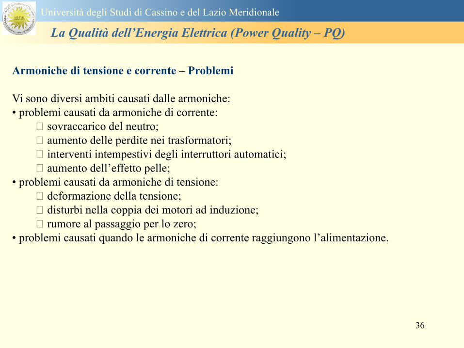
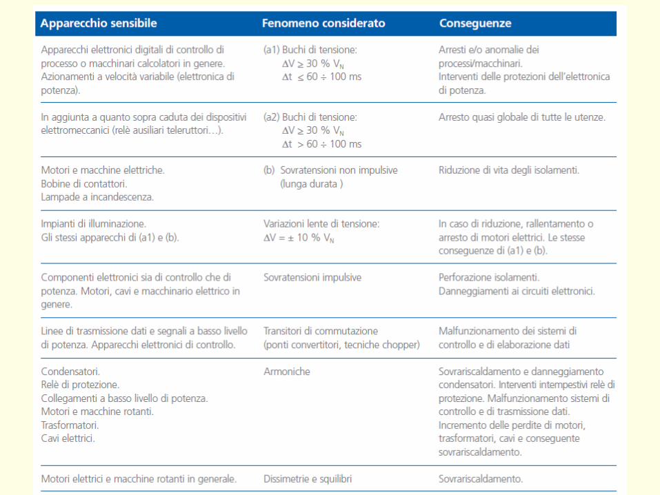
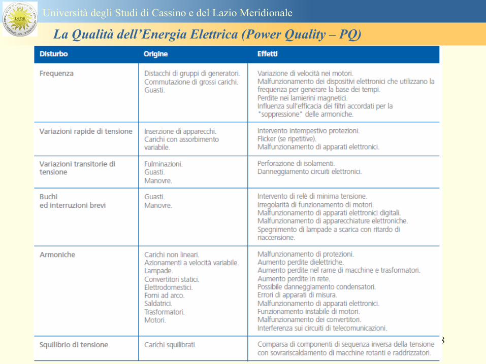
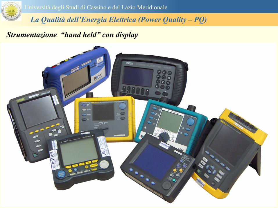
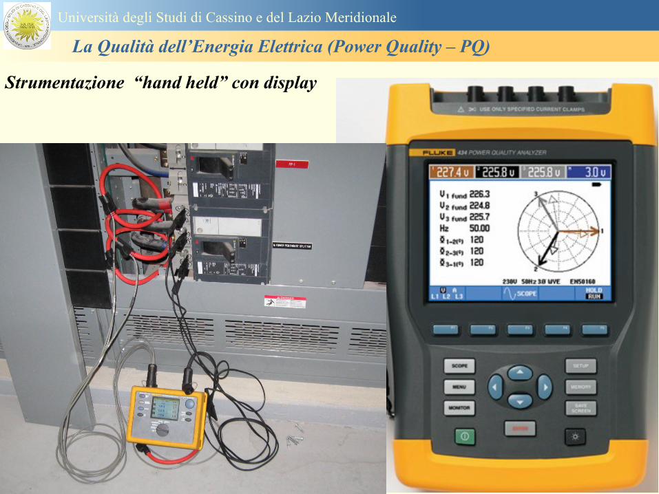
40
Strumentazione ldquohand heldrdquo con display
Universitagrave degli Studi di Cassino e del Lazio Meridionale
La Qualitagrave dellrsquoEnergia Elettrica (Power Quality ndash PQ)
41
Strumentazione da registrazione
Universitagrave degli Studi di Cassino e del Lazio Meridionale
La Qualitagrave dellrsquoEnergia Elettrica (Power Quality ndash PQ)
42
Schema di principio ndash 61000-4-30 copy IEC2008
The electrical quantity to be measured may be either directly accessible as is
generally the case in low-voltage systems or accessible via measurement
transducers
An instrument may include the whole measurement chain In this standard the
normative part does not consider the measurement transducers external to the
instrument and their associated uncertainty
Universitagrave degli Studi di Cassino e del Lazio Meridionale
La Qualitagrave dellrsquoEnergia Elettrica (Power Quality ndash PQ)
43
Universitagrave degli Studi di Cassino Corso di Fondamenti di Misure
La Qualitagrave dellrsquoEnergia Elettrica (Power Quality ndash PQ)
Classi dei metodi di misura - 61000-4-30 copy IEC2008
For each class measurement methods and appropriate performance requirements
are included
Sono definite tre classi A S e B
Class A
This class is used where precise measurements are necessary for example for contractual
applications that may require resolving disputes verifying compliance with standards etc
Any measurements of a parameter carried out with two different instruments complying with
the requirements of Class A when measuring the same signals will produce matching results
within the specified uncertainty for that parameter
Class S
This class is used for statistical applications such as surveys or power quality assessment
possibly with a limited subset of parameters Although it uses equivalent intervals of
measurement as class A the class S processing requirements are lower
Class B
This class is defined in order to avoid making many existing instruments designs obsolete
NOTE Class B methods are not recommended for new designs Readers are advised that Class B may be removed in a
future Edition of this standard
44
Classi dei metodi di misura - 61000-4-30 copy IEC2008
Measurement aggregation over time intervals
CLASS A
The basic measurement time interval for parameter magnitudes (supply voltage harmonics
interharmonics and unbalance) shall be a 10-cycle time interval for a 50 Hz power system
or 12-cycle time interval for a 60 Hz power system
The 1012-cycle measurement shall be re-synchronized at every RTC 10 min tick
The 1012-cycle values are then aggregated over 3 additional intervals
ndash 150180-cycle interval (150 cycles for 50 Hz nominal or 180 cycles for 60 Hz nominal)
ndash 10 min interval
ndash 2 h interval
CLASS S
Same time intervals as Class A
CLASS B
The manufacturer shall specify the number and duration of aggregation time intervals
Universitagrave degli Studi di Cassino e del Lazio Meridionale
La Qualitagrave dellrsquoEnergia Elettrica (Power Quality ndash PQ)
45
Universitagrave degli Studi di Cassino e del Lazio Meridionale
La Qualitagrave dellrsquoEnergia Elettrica (Power Quality ndash PQ)
46
Universitagrave degli Studi di Cassino e del Lazio Meridionale
La Qualitagrave dellrsquoEnergia Elettrica (Power Quality ndash PQ)
Class A
The 10-min aggregated value shall be tagged with the absolute time (for
example 01H1000) The time tag is the time at the conclusion of the 10-min
aggregation
The data for the 10-min time interval shall be aggregated from 1012-cycle time
intervals
Each 10-minute interval shall begin on a UTC 10-min tick The 10-min tick is
also used to re-synchronize the 1012-cycle intervals and the 150180-cycle
intervals
The final 1012-cycle interval(s) in a 10-min aggregation period will typically
overlap in time with the UTC 10-min clock tick Any overlapping 1012-cycle
interval (Overlap 1 in Figure 2) is included in the aggregation of the previous
10-min interval
47
Universitagrave degli Studi di Cassino e del Lazio Meridionale
La Qualitagrave dellrsquoEnergia Elettrica (Power Quality ndash PQ)
48
Universitagrave degli Studi di Cassino e del Lazio Meridionale
La Qualitagrave dellrsquoEnergia Elettrica (Power Quality ndash PQ)
49
Classi dei metodi di misura - 61000-4-30 copy IEC2008
Real time clock (RTC) uncertainty
Sono definite le specifiche per le 3 classi
Flagging concept
During a dip swell or interruption the measurement algorithm for other
parameters (for example frequency measurement) might produce an unreliable
value The flagging concept therefore avoids counting a single event more than
once in different parameters (for example counting a single dip as both a dip and a
frequency variation) and indicates that an aggregated value might be unreliable
Universitagrave degli Studi di Cassino e del Lazio Meridionale
La Qualitagrave dellrsquoEnergia Elettrica (Power Quality ndash PQ)
50
Classi dei metodi di misura - 61000-4-30 copy IEC2008
Power quality parameters - INDICES
Per ogni parametro viene suggerito il metodo di misura per le tre classi e
(soprattutto) le caratteristiche di precisione Per alcuni parametri rimanda a
specifiche norme (ad esempio Flicker e Armonicheinterarmoniche)
Esempio - Power frequency Class A
The frequency reading shall be obtained every 10 s As power frequency may not be exactly 50 Hz or 60
Hz within the 10 s time clock interval the number of cycles may not be an integer number The
fundamental frequency output is the ratio of the number of integral cycles counted during the 10 s time
clock interval divided by the cumulative duration of the integer cycles Before each assessment
harmonics and interharmonics shall be attenuated to minimize the effects of multiple zero crossings
The measurement time intervals shall be non-overlapping Individual cycles that overlap the 10 s time
clock are discarded Each 10 s interval shall begin on an absolute 10 s time clock with uncertainty as
defined in 46
Other techniques that provide equivalent results such as convolution are acceptable
Class S Same as class A
Class B The manufacturer shall specify the process used for frequency measurement
Universitagrave degli Studi di Cassino e del Lazio Meridionale
La Qualitagrave dellrsquoEnergia Elettrica (Power Quality ndash PQ)
51
Classi dei metodi di misura - 61000-4-30 copy IEC2008
Power quality parameters - INDICES
Per ogni parametro viene suggerito il metodo di misura per le tre classi e
(soprattutto) le caratteristiche di precisione Per alcuni parametri rimanda a
specifiche norme (ad esempio Flicker e Armonicheinterarmoniche)
Esempio - Power frequency
Measurement uncertainty and measuring range
ndash Class A
Under the conditions described in 61 the measurement uncertainty shall not exceed
plusmn10 mHz over the measuring ranges 425 Hz ~ 575 Hz 51 Hz ~ 69 Hz
ndash Class S
Under the conditions described in 61 the measurement uncertainty shall not exceed
plusmn50 mHz over the measuring ranges 425 Hz ~ 575 Hz 51 Hz ~ 69 Hz
ndash Class B
The manufacturer shall specify the uncertainty over the measuring ranges 425 Hz ~
575 Hz 51 Hz ~ 69 Hz
Universitagrave degli Studi di Cassino e del Lazio Meridionale
La Qualitagrave dellrsquoEnergia Elettrica (Power Quality ndash PQ)
52
Magnitude of the supply voltage
Measurement method
ndash Class A
The measurement shall be the rms value of the voltage magnitude over
a 10-cycle time interval for 50 Hz power system or 12-cycle time
interval for 60 Hz power system Every 1012-cycle interval shall be
contiguous and not overlapping with adjacent 1012-cycle intervals
except as shown as Overlap 1 in Figure 2
NOTE 1 This specific measurement method is used for quasi-stationary signals and is
not used for the detection and measurement of disturbances dips swells voltage
interruptions and transients
NOTE 2 The rms value includes by definition harmonics interharmonics mains
signalling etc
- Class S same as Class A
Universitagrave degli Studi di Cassino e del Lazio Meridionale
La Qualitagrave dellrsquoEnergia Elettrica (Power Quality ndash PQ)
53
Magnitude of the supply voltage
Measurement uncertainty and measuring range
ndash Class A
Under the conditions described in Clause 6 the measurement uncertainty
shall not exceed plusmn01 of Udin over the range of 10 ~ 150 of Udin
ndash Class S
Under the conditions described in Clause 6 the measurement uncertainty
shall not exceed plusmn05 of Udin over the range of 20 ~ 120 of Udin
Universitagrave degli Studi di Cassino e del Lazio Meridionale
La Qualitagrave dellrsquoEnergia Elettrica (Power Quality ndash PQ)
54
Supply voltage dips and swells
Measurement method
ndash Class A
The basic measurement Urms of a voltage dip and swell shall be the
Urms(frac12) on each measurement channel (see Clause 322)
The cycle duration for Urms(frac12) depends on the frequency The
frequency might be determined by the last non-flagged power frequency
measurement (see Clause 47 and Clause 51) or by any other method
that yields the uncertainty requirements of Clause 6
NOTE 1 The Urms(frac12) value includes by definition harmonics interharmonics mains
signalling voltage etc
NOTE 2 It is important to avoid loss of data when dips and swells occur in a rapid
sequence (for example three events in one second with up to one minute between
sequences may occur when a recloser operates into a sustained fault) If during a rapid
burst the dipswell event characteristics cannot be recorded then a count of events may
be useful
Universitagrave degli Studi di Cassino e del Lazio Meridionale
La Qualitagrave dellrsquoEnergia Elettrica (Power Quality ndash PQ)
55
Supply voltage dips and swells
Detection and evaluation of a voltage dip
Voltage dip detection
The dip threshold is a percentage of either Udin or the sliding voltage
reference Usr (see 525 544) The user shall declare the reference
voltage in use
NOTE ndash On single-phase systems a voltage dip begins when the Urms voltage falls
below the dip threshold and ends when the Urms voltage is equal to or above the dip
threshold plus the hysteresis voltage
ndash On polyphase systems a dip begins when the Urms voltage of one or more channels is
below the dip threshold and ends when the Urms voltage on all measured channels is
equal to or above the dip threshold plus the hysteresis voltage
The dip threshold and the hysteresis voltage are both set by the user according to the
use
Universitagrave degli Studi di Cassino e del Lazio Meridionale
La Qualitagrave dellrsquoEnergia Elettrica (Power Quality ndash PQ)
56
Calculation of a sliding reference voltage
The sliding reference voltage implementation is optional not mandatory
If a sliding reference is chosen for voltage dip or swell detection this
shall be calculated using a first-order filter with a 1-min time constant
This filter is given by
Usr(n) = 09967 times Usr(nndash1) + 00033 times U(1012)rms
where
Usr(n) is the present value of the sliding reference voltage
Usr(nndash1) is the previous value of the sliding reference voltage and
U(1012)rms is the most recent 1012-cycle rms value
When the measurement is started the initial value of the sliding reference voltage is set
to the declared input voltage The sliding reference voltage is updated every 1012-
cycles If a 1012-cycle value is flagged the sliding reference voltage is not updated
and the previous value is used
Universitagrave degli Studi di Cassino e del Lazio Meridionale
La Qualitagrave dellrsquoEnergia Elettrica (Power Quality ndash PQ)
57
Supply voltage dips and swells
Voltage dip evaluation
A voltage dip is characterized by a pair of data either residual voltage
(Ures) or depth and duration
ndash the residual voltage of a voltage dip is the lowest Urms(frac12) value
measured on any channel during the dip
ndash the depth is the difference between the reference voltage (either Udin
or Usr) and the residual voltage It is generally expressed in percentage
of the reference voltage
NOTE 1 During the dip it may be useful to also record the lowest Urms(frac12) on each
channel in addition to the residual voltage of the dip The duration spent below the dip
threshold on each channel may also be useful
Universitagrave degli Studi di Cassino e del Lazio Meridionale
La Qualitagrave dellrsquoEnergia Elettrica (Power Quality ndash PQ)
58
Supply voltage dips and swells
Voltage dip evaluation
NOTE 2 If voltage waveforms are recorded before during and after a
dip useful information about phase angle changes may be available in
the recorded data
The start time of a dip shall be time stamped with the time of the start of
the Urms of the channel that initiated the event and the end time of the
dip shall be the time stamped with the time of the end of the Urms that
ended the event as defined by the threshold plus the hysteresis
The duration of a voltage dip is the time difference between the start
time and the end time of the voltage dip
Universitagrave degli Studi di Cassino e del Lazio Meridionale
La Qualitagrave dellrsquoEnergia Elettrica (Power Quality ndash PQ)
59
Supply voltage dips and swells
Residual voltage and swell voltage magnitude measurement
uncertainty
ndash Class A
The measurement uncertainty shall not exceed plusmn02 of Udin
ndash Class S
The measurement uncertainty shall not exceed plusmn10 of Udin
Universitagrave degli Studi di Cassino e del Lazio Meridionale
La Qualitagrave dellrsquoEnergia Elettrica (Power Quality ndash PQ)
60
Schema di principio ndash 61000-4-7 copy IEC2002
Universitagrave degli Studi di Cassino e del Lazio Meridionale
La Qualitagrave dellrsquoEnergia Elettrica (Power Quality ndash PQ)
61
Universitagrave degli Studi di Cassino e del Lazio Meridionale
La Qualitagrave dellrsquoEnergia Elettrica (Power Quality ndash PQ)
62
Universitagrave degli Studi di Cassino e del Lazio Meridionale
La Qualitagrave dellrsquoEnergia Elettrica (Power Quality ndash PQ)
63
Inter-Armoniche Le inter-armoniche sono tensioni o correnti sinusoidali con frequenza diversa da un
multiplo intero della fondamentale la cui presenza determina una distorsione
(modulazione) della forma donda della tensione di alimentazione
CAUSE dai carichi che assorbono correnti inter-armoniche
- carichi commutati elettronicamente convertitori cascata subsincrona cicloconvertitori regolatori con
controllo a pacchetti di cicli ecc
- carichi con caratteristiche non lineari eo non stazionarie forni ad arco saldatrici ad arco ecc
Universitagrave degli Studi di Cassino e del Lazio Meridionale
La Qualitagrave dellrsquoEnergia Elettrica (Power Quality ndash PQ)
64
Universitagrave degli Studi di Cassino e del Lazio Meridionale
La Qualitagrave dellrsquoEnergia Elettrica (Power Quality ndash PQ)
Un porsquo di esempi e
consigli praticihellip
65
0V
50V
100V
150V
200V
250V
300V
350V
0ms 5ms 10ms 15ms 20ms
t
u
0A
1A
2A
3A
i
0V
50V
100V
150V
200V
250V
300V
350V
0ms 5ms 10ms 15ms 20ms
t
u
0A
1A
2A
3A
i
0V
50V
100V
150V
200V
250V
300V
350V
0ms 5ms 10ms 15ms 20ms
t
u
0A
1A
2A
3A
i
gleichgerichtete
Netzspannung
Kondensator-
spannung
gleichgerichteter
Netzstrom
The situation
today
bull Computed current and voltage profiles when a
230 V 58 W fluorescent lamp with an old-style
electronic ballast is driven on the phase wire of
a typical power distribution system
System voltage 230 V
System frequency 50 Hz
Source resistance 500 mW
Longitudinal induction 904 microH
System impedance 575 mW
Mean dc current 180 mA
Smoothing capacitance220 microF
66
And what about electronic ballasts that are rated over 25W
Introduce electronic power factor correction (PFC)
0V
20V
40V
60V
80V
100V
120V
140V
160V
180V
200V
220V
0deg 15deg 30deg 45deg
u
00A
03A
06A
09A
12A
i
67
Though todayrsquos ballasts are better if
rated gt25 W bull Only
the
small
ones
continu
e to
pollute
just like
PCs
TV sets
do
68
This leads to a number of
previously unknown effects bull 1 Deformed voltage curves
bull 2 Huge inrush current peaks
bull 3 Instrument dependent measured parameters
bull 4 Increased loading of phase conductors
bull 5 Loading and overloading of the neutral conductor
bull 6 Overheating and start-up problems of induction motors
bull 7 Additional stray losses in transformers
bull 8 Repercussions of generators upon the mains
bull 9 Influence of capacitors repercussions upon the mains
and four additional complications in TN-C systems
10 Stray currents in equipotential bonding system magnetic fields
11 Contamination of data streams by stray currents
12 Stray currents in the earthing system corrosion damage
13 Lightning currents in devices and equipment
69
1 Deformed voltage curves
bull in theory
-350V
-300V
-250V
-200V
-150V
-100V
-50V
0V
50V
100V
150V
200V
250V
300V
350V
0 5 10 15 20
t ms
u
System voltage profile when driving
a single-phase load comprising
twenty 58 W energy-saver lamps in
parallel on a typical 230 V power
system
70
and in practice
bull An actual
current profile
bull
bull and
bull a voltage profile
bull
bull recorded in a large storage
dispatch and administrative
building
71
at home or in industrial environments
bull
bull Television 40
W
bull 200 Vdiv 2
Adiv
bull 5 msdiv
Harmonic
spectrum
Frequency
converter
50 Adiv
Phase currents
I1=I2=I3=160 A
IN=295 A
5 msdiv
72
Every periodic waveform can be written
as the infinite sum of sinusoidal waves
-175
-150
-125
-100
-75
-50
-25
0
25
50
75
100
125
150
175
0 5 10 15 20
t ms
i
mA
itot
i1
Synthesis of a triangular current profile 100mA
Content fundamental I = 99 mA Isup2 = 9855 mAsup2
Sum of squares Isup2 = 9855 mAsup2
Root of sum = RMS value I = 99 mA
-175
-150
-125
-100
-75
-50
-25
0
25
50
75
100
125
150
175
0 5 10 15 20
t ms
i
mA
itot
i1
i3
Synthesis of a triangular current profile 100mA
Content fundamental I = 99 mA Isup2 = 9855 mAsup2
Cont 3 rd harmonic I = -11 mA Isup2 = 122 mAsup2
Sum of squares Isup2 = 9977 mAsup2
Root of sum = RMS value I = 100 mA
-175
-150
-125
-100
-75
-50
-25
0
25
50
75
100
125
150
175
0 5 10 15 20
t ms
i
mA
itot
i1
i3
i5
Synthesis of a triangular current profile 100mA
Content fundamental I = 99 mA Isup2 = 9855 mAsup2
Cont 3 rd harmonic I = -11 mA Isup2 = 122 mAsup2
Cont 5 th harmonic I = 4 mA Isup2 = 16 mAsup2
Sum of squares Isup2 = 9993 mAsup2
Root of sum = RMS value I = 100 mA
-175
-150
-125
-100
-75
-50
-25
0
25
50
75
100
125
150
175
0 5 10 15 20
t ms
i
mA
itot
i1
i3
i5
i7
Synthesis of a triangular current profile 100mA
Content fundamental I = 99 mA Isup2 = 9855 mAsup2
Cont 3 rd harmonic I = -11 mA Isup2 = 122 mAsup2
Cont 5 th harmonic I = 4 mA Isup2 = 16 mAsup2
Cont 7 th harmonic I = -2 mA Isup2 = 4 mAsup2
Sum of squares Isup2 = 9997 mAsup2
Root of sum = RMS value I = 100 mA
-175
-150
-125
-100
-75
-50
-25
0
25
50
75
100
125
150
175
0 5 10 15 20
t ms
i
mA
itot i1
i3 i5
i7 i9
Synthesis of a triangular current profile 100mA
Content fundamental I = 99 mA Isup2 = 9855 mAsup2
Cont 3 rd harmonic I = -11 mA Isup2 = 122 mAsup2
Cont 5 th harmonic I = 4 mA Isup2 = 16 mAsup2
Cont 7 th harmonic I = -2 mA Isup2 = 4 mAsup2
Cont 9 th harmonic I = 1 mA Isup2 = 2 mAsup2
Sum of squares Isup2 = 9998 mAsup2
Root of sum = RMS value I = 100 mA
-175
-150
-125
-100
-75
-50
-25
0
25
50
75
100
125
150
175
0 5 10 15 20
t ms
i
mA
itot i1
i3 i5
i7 i9
i11
Synthesis of a triangular current profile 100mA
Content fundamental I = 99 mA Isup2 = 9855 mAsup2
Cont 3 rd harmonic I = -11 mA Isup2 = 122 mAsup2
Cont 5 th harmonic I = 4 mA Isup2 = 16 mAsup2
Cont 7 th harmonic I = -2 mA Isup2 = 4 mAsup2
Cont 9 th harmonic I = 1 mA Isup2 = 2 mAsup2
Cont 11 th harmonic I = -1 mA Isup2 = 1 mAsup2
Sum of squares Isup2 = 9999 mAsup2
Root of sum = RMS value I = 100 mA
-175
-150
-125
-100
-75
-50
-25
0
25
50
75
100
125
150
175
0 5 10 15 20
t ms
i
mA
itot i1
i3 i5
i7 i9
i11 i13
Synthesis of a triangular current profile 100mA
Content fundamental I = 99 mA Isup2 = 9855 mAsup2
Cont 3 rd harmonic I = -11 mA Isup2 = 122 mAsup2
Cont 5 th harmonic I = 4 mA Isup2 = 16 mAsup2
Cont 7 th harmonic I = -2 mA Isup2 = 4 mAsup2
Cont 9 th harmonic I = 1 mA Isup2 = 2 mAsup2
Cont 11 th harmonic I = -1 mA Isup2 = 1 mAsup2
Cont 13 th harmonic I = 1 mA Isup2 = 0 mAsup2
Sum of squares Isup2 = 9999 mAsup2
Root of sum = RMS value I = 100 mA
-175
-150
-125
-100
-75
-50
-25
0
25
50
75
100
125
150
175
0 5 10 15 20
t ms
i
mA
itot i1
i3 i5
i7 i9
i11 i13
i15
Synthesis of a triangular current profile 100mA
Content fundamental I = 99 mA Isup2 = 9855 mAsup2
Cont 3 rd harmonic I = -11 mA Isup2 = 122 mAsup2
Cont 5 th harmonic I = 4 mA Isup2 = 16 mAsup2
Cont 7 th harmonic I = -2 mA Isup2 = 4 mAsup2
Cont 9 th harmonic I = 1 mA Isup2 = 2 mAsup2
Cont 11 th harmonic I = -1 mA Isup2 = 1 mAsup2
Cont 13 th harmonic I = 1 mA Isup2 = 0 mAsup2
Cont 15 th harmonic I = 0 mA Isup2 = 0 mAsup2
Sum of squares Isup2 = 10000 mAsup2
Root of sum = RMS value I = 100 mA
-175
-150
-125
-100
-75
-50
-25
0
25
50
75
100
125
150
175
0 5 10 15 20
t ms
i
mA
itot i1
i3 i5
i7 i9
i11 i13
i15 i17
Synthesis of a triangular current profile 100mA
Content fundamental I = 99 mA Isup2 = 9855 mAsup2
Cont 3 rd harmonic I = -11 mA Isup2 = 122 mAsup2
Cont 5 th harmonic I = 4 mA Isup2 = 16 mAsup2
Cont 7 th harmonic I = -2 mA Isup2 = 4 mAsup2
Cont 9 th harmonic I = 1 mA Isup2 = 2 mAsup2
Cont 11 th harmonic I = -1 mA Isup2 = 1 mAsup2
Cont 13 th harmonic I = 1 mA Isup2 = 0 mAsup2
Cont 15 th harmonic I = 0 mA Isup2 = 0 mAsup2
Cont 17 th harmonic I = 0 mA Isup2 = 0 mAsup2
Sum of squares Isup2 = 10000 mAsup2
Root of sum = RMS value I = 100 mA
73
whose frequencies called harmonics are
integer multiples of the fundamental frequency
-175
-150
-125
-100
-75
-50
-25
0
25
50
75
100
125
150
175
0 5 10 15 20
t ms
i
mA
itot
i1
Synthesis of a rectangular current profile 100mA
Content fundamental I = 90 mA Isup2 = 8106 mAsup2
Sum of squares Isup2 = 8106 mAsup2
Root of sum = RMS value I = 90 mA
-175
-150
-125
-100
-75
-50
-25
0
25
50
75
100
125
150
175
0 5 10 15 20
t ms
i
mA
itot
i1
i3
Synthesis of a rectangular current profile 100mA
Content fundamental I = 90 mA Isup2 = 8106 mAsup2
Cont 3 rd harmonic I = 30 mA Isup2 = 901 mAsup2
Sum of squares Isup2 = 9006 mAsup2
Root of sum = RMS value I = 95 mA
-175
-150
-125
-100
-75
-50
-25
0
25
50
75
100
125
150
175
0 5 10 15 20
t ms
i
mA
itot
i1
i3
i5
Synthesis of a rectangular current profile 100mA
Content fundamental I = 90 mA Isup2 = 8106 mAsup2
Cont 3 rd harmonic I = 30 mA Isup2 = 901 mAsup2
Cont 5 th harmonic I = 18 mA Isup2 = 324 mAsup2
Sum of squares Isup2 = 9331 mAsup2
Root of sum = RMS value I = 97 mA
-175
-150
-125
-100
-75
-50
-25
0
25
50
75
100
125
150
175
0 5 10 15 20
t ms
i
mA
itot
i1
i3
i5
i7
Synthesis of a rectangular current profile 100mA
Content fundamental I = 90 mA Isup2 = 8106 mAsup2
Cont 3 rd harmonic I = 30 mA Isup2 = 901 mAsup2
Cont 5 th harmonic I = 18 mA Isup2 = 324 mAsup2
Cont 7 th harmonic I = 13 mA Isup2 = 165 mAsup2
Sum of squares Isup2 = 9496 mAsup2
Root of sum = RMS value I = 97 mA
-175
-150
-125
-100
-75
-50
-25
0
25
50
75
100
125
150
175
0 5 10 15 20
t ms
i
mA
itot i1
i3 i5
i7 i9
Synthesis of a rectangular current profile 100mA
Content fundamental I = 90 mA Isup2 = 8106 mAsup2
Cont 3 rd harmonic I = 30 mA Isup2 = 901 mAsup2
Cont 5 th harmonic I = 18 mA Isup2 = 324 mAsup2
Cont 7 th harmonic I = 13 mA Isup2 = 165 mAsup2
Cont 9 th harmonic I = 10 mA Isup2 = 100 mAsup2
Sum of squares Isup2 = 9596 mAsup2
Root of sum = RMS value I = 98 mA
-175
-150
-125
-100
-75
-50
-25
0
25
50
75
100
125
150
175
0 5 10 15 20
t ms
i
mA
itot i1
i3 i5
i7 i9
i11
Synthesis of a rectangular current profile 100mA
Content fundamental I = 90 mA Isup2 = 8106 mAsup2
Cont 3 rd harmonic I = 30 mA Isup2 = 901 mAsup2
Cont 5 th harmonic I = 18 mA Isup2 = 324 mAsup2
Cont 7 th harmonic I = 13 mA Isup2 = 165 mAsup2
Cont 9 th harmonic I = 10 mA Isup2 = 100 mAsup2
Cont 11 th harmonic I = 8 mA Isup2 = 67 mAsup2
Sum of squares Isup2 = 9663 mAsup2
Root of sum = RMS value I = 98 mA
-175
-150
-125
-100
-75
-50
-25
0
25
50
75
100
125
150
175
0 5 10 15 20
t ms
i
mA
itot i1
i3 i5
i7 i9
i11 i13
Synthesis of a rectangular current profile 100mA
Content fundamental I = 90 mA Isup2 = 8106 mAsup2
Cont 3 rd harmonic I = 30 mA Isup2 = 901 mAsup2
Cont 5 th harmonic I = 18 mA Isup2 = 324 mAsup2
Cont 7 th harmonic I = 13 mA Isup2 = 165 mAsup2
Cont 9 th harmonic I = 10 mA Isup2 = 100 mAsup2
Cont 11 th harmonic I = 8 mA Isup2 = 67 mAsup2
Cont 13 th harmonic I = 7 mA Isup2 = 48 mAsup2
Sum of squares Isup2 = 9711 mAsup2
Root of sum = RMS value I = 99 mA
-175
-150
-125
-100
-75
-50
-25
0
25
50
75
100
125
150
175
0 5 10 15 20
t ms
i
mA
itot i1
i3 i5
i7 i9
i11 i13
i15
Synthesis of a rectangular current profile 100mA
Content fundamental I = 90 mA Isup2 = 8106 mAsup2
Cont 3 rd harmonic I = 30 mA Isup2 = 901 mAsup2
Cont 5 th harmonic I = 18 mA Isup2 = 324 mAsup2
Cont 7 th harmonic I = 13 mA Isup2 = 165 mAsup2
Cont 9 th harmonic I = 10 mA Isup2 = 100 mAsup2
Cont 11 th harmonic I = 8 mA Isup2 = 67 mAsup2
Cont 13 th harmonic I = 7 mA Isup2 = 48 mAsup2
Cont 15 th harmonic I = 6 mA Isup2 = 36 mAsup2
Sum of squares Isup2 = 9747 mAsup2
Root of sum = RMS value I = 99 mA
-175
-150
-125
-100
-75
-50
-25
0
25
50
75
100
125
150
175
0 5 10 15 20
t ms
i
mA
itot i1
i3 i5
i7 i9
i11 i13
i15 i17
Synthesis of a rectangular current profile 100mA
Content fundamental I = 90 mA Isup2 = 8106 mAsup2
Cont 3 rd harmonic I = 30 mA Isup2 = 901 mAsup2
Cont 5 th harmonic I = 18 mA Isup2 = 324 mAsup2
Cont 7 th harmonic I = 13 mA Isup2 = 165 mAsup2
Cont 9 th harmonic I = 10 mA Isup2 = 100 mAsup2
Cont 11 th harmonic I = 8 mA Isup2 = 67 mAsup2
Cont 13 th harmonic I = 7 mA Isup2 = 48 mAsup2
Cont 15 th harmonic I = 6 mA Isup2 = 36 mAsup2
Cont 17 th harmonic I = 5 mA Isup2 = 28 mAsup2
Sum of squares Isup2 = 9775 mAsup2
Root of sum = RMS value I = 99 mA
74
Even far better simulations are
available free of charge at
bull wwwpowerstandardscomMcEachern
75
-4A
-3A
-2A
-1A
0A
1A
2A
3A
4A
0ms 5ms 10ms 15ms 20ms
t
i
-4A
-3A
-2A
-1A
0A
1A
2A
3A
4A
0ms 5ms 10ms 15ms 20ms
t
i
Applying the Fourier
analysis to a real PC
current does not work
directly
bull
bull but it can be
modelled by a similar
triangular curve in
which not all of the
higher harmonics
have been included
Triangular current profile of
the same amplitude and a
pulse duty cycle of 17
Input current of a PC
with monitor
76
Analysis of the model triangular waveform
-400
-350
-300
-250
-200
-150
-100
-50
0
50
100
150
200
250
300
350
400
0 5 10 15 20
t ms
iI
itot(t) L1 [A] i1(t) L1 [A]
i3(t) L1 [A] i5(t) L1 [A]
i7(t) L1 [A] i9(t) L1 [A]
i11(t) L1 [A] i13(t) L1 [A]
i15(t) L1 [A] i17(t) L1 [A]
77
M3
Harmonics
Energy
(active
power)
L1
L2
L3
N
PE
Important
bull Harmonics are created within the loads
themselves and can flow ldquoupstreamrdquo to
contaminate the power system
78
-6A
-5A
-4A
-3A
-2A
-1A
0A
1A
2A
3A
4A
5A
6A
0ms 5ms 10ms 15ms 20ms
t
i
Squared values
Without
Fundamental 502 mA 251986 mAsup2 the fundamental
3rd harmonic -479 mA 229000 mAsup2 229000 mAsup2
5th harmonic 434 mA 188595 mAsup2 188595 mAsup2
7th harmonic -374 mA 139903 mAsup2 139903 mAsup2
9th harmonic 304 mA 92527 mAsup2 92527 mAsup2
11th harmonic -232 mA 53671 mAsup2 53671 mAsup2
13th harmonic 163 mA 26600 mAsup2 26600 mAsup2
15th harmonic -104 mA 10780 mAsup2 10780 mAsup2
17th harmonic 57 mA 3299 mAsup2 3299 mAsup2
Sum of the squares 996362 mAsup2 744377 mAsup2
Root thereof 998 mAeff THD = 863 mA
What actually is THD Example shown here triangular current
profile with an rms current of 1000 mA
and a pulse duty cycle of 17
THDr (root mean square) = 863mA1000mA = 86
THDf (fundamental) = 863mA502mA = 172
79
Effect on phase-to-neutral
and phase-to-phase voltages
bull Recorded
on June
30 2002
230 p
m
bull What
was the
matter
then
bull The
soccer
final
Germany
vs
Brazil
80
The triple-N harmonics drive
a circulating current in the
delta winding of a distribution
transformer
bull but the
bull voltage harmonics
propagate into the next
low-voltage power
distribution system
81 0V
50V
100V
150V
200V
250V
300V
350V
400V
450V
500V
550V
0 10 20 30 40 50
t ms
u
0A
10A
20A
30A
40A
50A
60A
70A
80A
90A
100A
110A
120A
130A
140A
150A
i
Switching on just as supply voltage passes through zero
0V
50V
100V
150V
200V
250V
300V
350V
400V
450V
500V
550V
0 10 20 30 40 50
t ms
u
0A
10A
20A
30A
40A
50A
60A
70A
80A
90A
100A
110A
120A
130A
140A
150A
i
Switching on just as supply voltage is at its peak
2 Huge inrush current peaks
ndash in theory
82
and in practice
bull Inrush current of a
compact energy-
saver lamp and its
effect on the system
voltage (recorded at
the Technical
University of
Budapest)
bull
83
enables us to infer what
happens when run by a
normal three-phase supply
The same fluorescent lamp
with a magnetic ballast
bull The behaviour measured
when connected to
a dc supply
bull
Behaviour of a 58 W fluorescent lamp connected to a dc
supply
0
20
40
60
80
100
120
140
160
180
200
0 200 400 600 800 1000 1200
i mA
u
V
Measurement
Behaviour of a 58 W fluorescent lamp connected to a dc
supply
0
20
40
60
80
100
120
140
160
180
200
0 200 400 600 800 1000 1200
i mA
u
V
MeasurementCalculation
-350
-300
-250
-200
-150
-100
-50
0
50
100
150
200
250
300
350
0 5 10 15 20
t ms
u
V
-10
-08
-06
-04
-02
00
02
04
06
08
10
i
A
Systems voltage
Current
-350
-300
-250
-200
-150
-100
-50
0
50
100
150
200
250
300
350
0 5 10 15 20
t ms
u
V
-10
-08
-06
-04
-02
00
02
04
06
08
10
i
A
Systems voltage
Lamp voltage
Current
84
Warning ldquoCompensationrdquo is not
always what you think it is
bull Distinguish
between
bull Reactive
power
compensatio
n
aka power
factor
correction
Remedial
measure
Parallel (or
sometimes series)
compensation
using capacitors
Filter circuits
tuned to the
individual harmonic
frequencies
Harmonic
compensation
85
5 (Over)loading the neutral conductor
bull Magnetic ballast Old-style electronic ballast
-25A
-20A
-15A
-10A
-05A
00A
05A
10A
15A
20A
25A
0 5 10 15 20
t ms i
i(t) N
-25A
-20A
-15A
-10A
-05A
00A
05A
10A
15A
20A
25A
0 5 10 15 20
t ms
i
i(t) N
-25A
-20A
-15A
-10A
-05A
00A
05A
10A
15A
20A
25A
0 5 10 15 20
t ms
i
i(t) L1 i(t) L2 i(t) L3
-25A
-20A
-15A
-10A
-05A
00A
05A
10A
15A
20A
25A
0 5 10 15 20
t ms
i
i(t) L1
i(t) L2
i(t) L3
86
Adding the 3rd
harmonics
in the
neutral
wire
-150-100-50
050
100150
0deg 30deg 60deg 90deg 120deg 150deg 180deg 210deg 240deg 270deg 300deg 330deg 360deg
L1
-150-100-50
050
100150
0deg 30deg 60deg 90deg 120deg 150deg 180deg 210deg 240deg 270deg 300deg 330deg 360deg
L2
-150-100-50
050
100150
0deg 30deg 60deg 90deg 120deg 150deg 180deg 210deg 240deg 270deg 300deg 330deg 360deg
L3
-450-400-350-300-250-200-150-100-50
050
100150200250300350400450
0deg 30deg 60deg 90deg 120deg 150deg 180deg 210deg 240deg 270deg 300deg 330deg 360deg
f
iicirc
N
Physics dictates
that at any
moment in time
the phase and
neutral currents
must sum to zero
87
Effect on a three-phase ac motor
appears almost identical
bull The same motor is being
driven
simultaneously in
these three modes
homopolar system
zero-sequence system
direct system
positive-sequence system
inverse system
negative-sequence system
88
The transformer
influences the load
89
but the load also effects
the transformer
Total transformer loss is
2
)()(
nom
nomCunomFeLossI
IPPP
While total transformer loss really is
2
)(
2
)(
2
)(
nomnom
nomad
nom
nomCu
nom
nomFeLossI
I
f
fP
I
IP
U
UPP
90
6 ldquosupplementaryrdquo additional losses
in transformers
can be calculated rapidly
using the following two
simple formulae 50
2
2
1
2
11
Nn
n
nqh
I
In
I
I
e
eK
50
1
2
1
1
50
1
2
Nn
n
nNn
n
nI
IIII
where
Oh well
perhaps a practical
example is clearer
1000 compact 11W
(15VA) energy-saver
lamps powered by a
15kVA transformer
uSC=4 Pa=01PCu
Harmonics of an Osram Dulux 11W
CFL and a serial impedance of
R =291Ω amp X L=113Ω
U U sup2 I L I Lsup2 P aP Cu
n V Vsup2 mA mAsup2
1 2302 529920 485 23523 56
3 83 689 371 13764 295
5 107 1145 203 4121 245
7 43 185 53 281 33
9 11 12 30 90 17
11 23 53 38 144 42
13 10 10 15 23 09
15 06 04 15 23 12
17 11 12 15 23 15
19 05 03 09 08 07
21 05 03 13 17 18
23 06 04 08 06 08
25 04 02 06 04 05
27 06 04 08 06 11
29 04 02 05 03 05
31 03 01 05 03 06
33 03 01 05 03 06
35 03 01 04 02 05
37 03 01 04 02 05
39 03 01 03 01 03
41 01 00 03 01 04
43 02 00 02 00 02
45 01 00 02 00 02
47 01 00 02 00 02
49 01 00 01 00 01
51 01 00 01 00 01
P aP Cu = 814814
etc
etc
91
Harmonics measurement on an
Osram Dulux 11W compact
fluorescent lamp
U U sup2 I L I Lsup2 P addP Cu
n V Vsup2 mA mAsup2
1 2327 541493 489 23912 37
3 06 04 391 15288 215
5 44 194 264 6970 273
7 23 53 200 4000 307
9 01 00 192 3686 467
11 01 00 166 2756 522
13 01 00 127 1613 427
15 01 00 110 1210 426
17 01 00 102 1040 471
19 01 00 87 757 428
21 01 00 77 593 409
23 01 00 73 533 441
25 01 00 61 372 364
27 01 00 49 240 274
29 01 00 42 176 232
31 01 00 36 130 195
33 01 00 30 90 153
35 01 00 33 109 209
37 01 00 31 96 206
39 01 00 25 63 149
41 01 00 25 63 164
43 01 00 25 63 181
45 01 00 19 36 114
47 01 00 18 32 112
49 01 00 19 36 136
51 01 00 16 26 104
P aP Cu = 7017
To some extent
the transformer
protects itself
bull Always remember to
consider it
bull If the influence of the
transformer upon the load
did not exist then the
influence of the load upon
the transformer would be
nearly 9 times as high
7017
etc
etc
92
Rule of thumb Select transformers 35
larger than specification by apparent
power would require
bull This suffices to err
on the safe side
even in the worst
case and can
hardly ever be
wrong since
maximum
efficiency always
lies between 25
and 50 of rated
load
Efficiency of a 1 MVA transformer plotted against loading
985
986
987
988
989
990
991
992
993
994
0 25 50 75 100 125
Relative load h
Design with max Cu loss and min Fe loss
Design with min Cu loss and max Fe loss
1 MVA oil transformer according to HD 428
93
Measured response of an 11 W
fluorescent lamp operated with a
magnetic ballast
94
We are
dealing with
a complex
problem
bull These
effects
are not
isolated
but are
mutuall
y inter-
depende
nt
Effects 2 3 and 5 can be demonstrated
on DKIrsquos display panel
95
A conventional approximately resistive-
inductive load
mA
N L1 L2 L3
Two conventional approximately
resistive-inductive loads Three conventional approximately
resistive-inductive loads
96
A modern electronic load
mA
N
Two modern electronic loads Three modern electronic loads
L1 L2 L3
97
Discoveries on a
refurbished
junction box
System voltage
(as trigger
signal)
Current in the
earthing
conductor
between the
consumer unit
and the
bonding
busbar
98
The TN-C system that was perfectly
adequate some years ago is unable to meet
present-day requirements
-6
-4
-2
0
2
4
6
0 5 10 15 20
t ms
i
A
-350
-300
-250
-200
-150
-100
-50
0
50
100
150
200
250
300
350
0 5 10 15 20
t ms
u
V
99
ldquoTHFrdquo
(third harmonic
filter) made in
Finland
In certain situations this affordable
filter can be of help
German
version ldquoTHXrdquo
100
0Ω
5 Ω
1 0 Ω
1 5 Ω
2 0 Ω
2 5 Ω
3 0 Ω
3 5 Ω
4 0 Ω
0Hz 50Hz 100Hz 150Hz 200Hz 250Hz 300Hz
f
Z
-90deg
-75deg
-60deg
-45deg
-30deg
-15deg
0deg
15deg
30deg
45deg
60deg
75deg
90deg
φ
Reactorreactance
Capacitorreactance
Parallelimpedace
Phase angle
Data and frequency response
of the filter
bull 1320 microF
bull 875
14 mW microH
101
The filter in use
bull In a nursery running sodium vapour lamps (500 kW)
In a typical office and administrative building
102
The EMC Transformer from Switzerland
7 The effects of stray magnetic fields
in TN-C systems
bull ldquoWhen we build transformers the first thing we focus on is complying with our customersrsquo
requirements and only then on complying with standards Why Because it is customer
needs and not standards that offer real scope for product innovationrdquo
103
8 In a TN-C system problems arise from data
streams and working currents mixing
bull Others who
have drawn
attention to
this source of
data
transmission
errors include
engineering
and insurance
companies experts
consultants and many
others besides
104
9 Increased corrosive damage
bull This (once) galvanized steel strip ndash the earth
electrode of a TN-C-S system ndash was located close
to the transformer station
Side facing
transformer
station
Side facing
transformer
station
Side facing away
from transformer
station
Side facing away
from transformer
station
105
bull WRONG RIGHT
Working currents have no place
in earthing systems and
protective conductors
106
10 Lightning currents
107
Which bridge to
cross which bridge to
burn
Sometimes you just donlsquot
believe what you see
This one will soon
look rather charred
IEC 60364-5-54
54343 If from any point of the installation the neutral and protective
functions are provided by separate conductors it is not permitted to
connect the neutral conductor to any other earthed part of the
installation
108
Well then the rest is no longer a
miracle
109
110
111
Another means of (over)loading the
neutral conductor
bull dc currents
Original ldquoFakerdquo
112
and their
effects U = 2285 V
I = 92 mA
P = 182 W
S = 209 VA
Q = 103 VAr
LF = 087
cos φ = 099
U = 2243 V
I = 126 A
P = 380 W
S = 2860 VA
Q = 2830 VAr
No-load current in a
toroidal-core
transformer
200 VA
-350-300
-250-200
-150-100
-500
50
100150
200250
300350
0 10 20 30 40
t ms
u
V
-12
-10
-8
-6
-4
-2
0
2
4
6
8
10
12
i
mA
Voltage
Current
No-load current in a toroidal-core
transformer 200 VA when
running a 1500 W
hairdryer at
half-power
in parallel
-350-300
-250-200
-150-100
-500
50
100150
200250
300350
0 5 10 15 20 25 30 35 40
t ms
u
V
-6
-5
-4
-3
-2
-1
0
1
2
3
4
5
6
i
A
Voltage
Current
113
The later models donlsquot do it any more
The EN 61000-3-2 has at least managed
to put an end to this approach
Domestic appliances Max 105 A of 2nd harmonic
114
An electrical engineering wonder
dc current generates ac voltage
115
Spicing things up with a pinch of HF
electronic halogen lamp transformers
116
Decorative HF reactors
117
Current and power loss as a function of voltage
00
02
04
06
08
10
12
14
16
18
0 40 80 120 160 200 240
U V
I
A
0
20
40
60
80
100
120
PV
W
I [A]
Pv [W]
Power loss capacitor voltage
and total voltage as a function of current
0
50
100
150
200
250
300
350
400
450
000 025 050 075 100 125 150
I A
U
V
0
5
10
15
20
25
30
35
40
45
50
PV
W
Utot [V] Eff
UR [V] Eff
Pv [W]
The passive
harmonic filter
made of readily
available
components
bull is both
reliable
118
and effective
bull befor
e
bull after
119
Half the solution has already been implemented
120
And if thatrsquos not enough
bull Passive filter circuits will do it
121
So what do we need to do
bull In low-voltage power distribution systems
Do not use cables in which the neutral or protective earth conductor has a
reduced cross-section
Use only 5-core cable Do not install TN-C- or TN-C-S systems
Be generous when dimensioning conductor cross-sections This helps to
reduce line voltage drops and thus reduces the effect of current distortions on
the voltage as well as lowering energy losses (see VDE 0298 Part 100)
Generously dimensioned conductors will have no problem coping with any
future increase in demand
Only use measuring instruments that display the true root mean square value
(TRMS meters)
In medium-voltage power distribution systems
Use a varied mix of distribution transformers with different vector groups
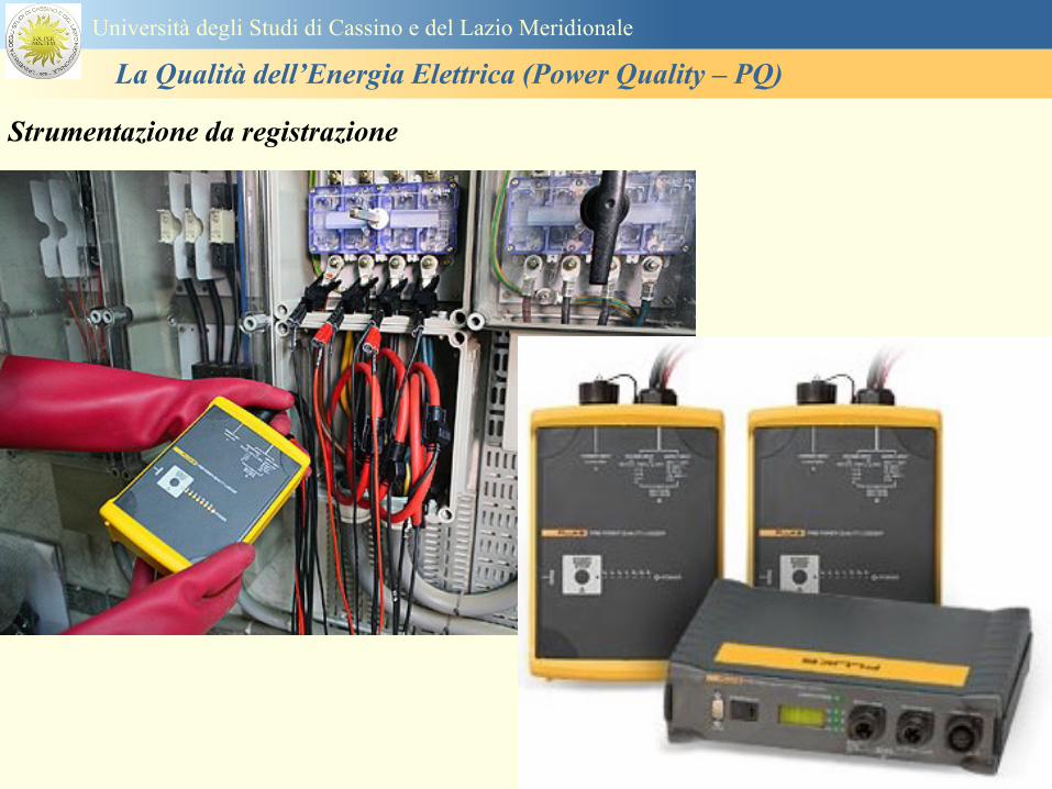
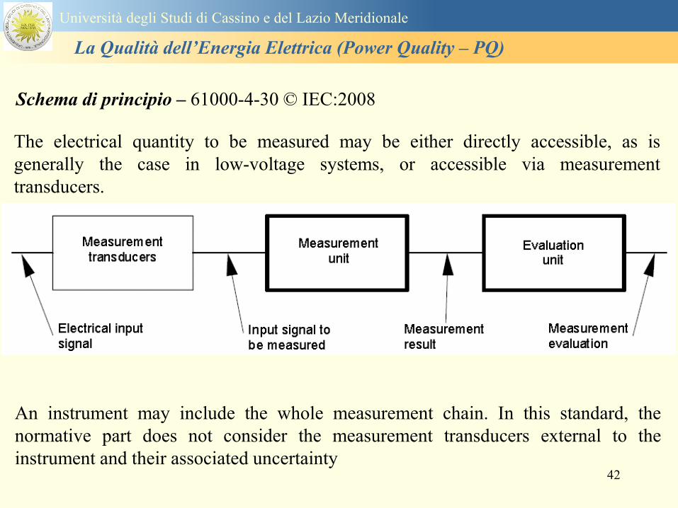
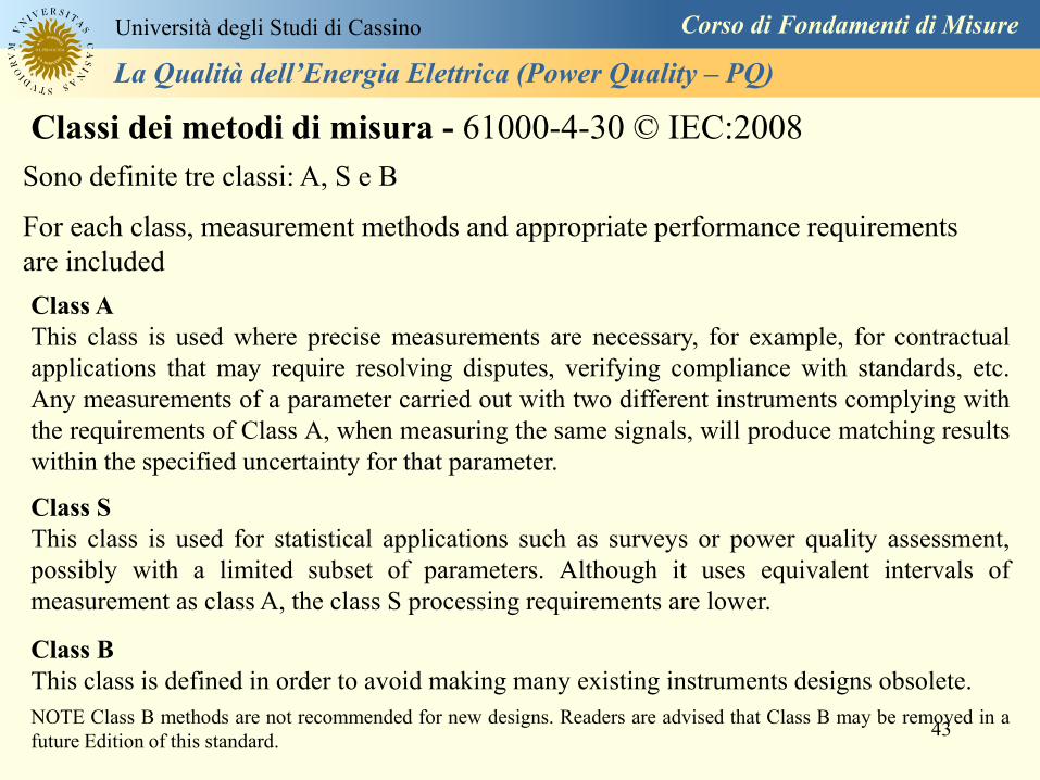
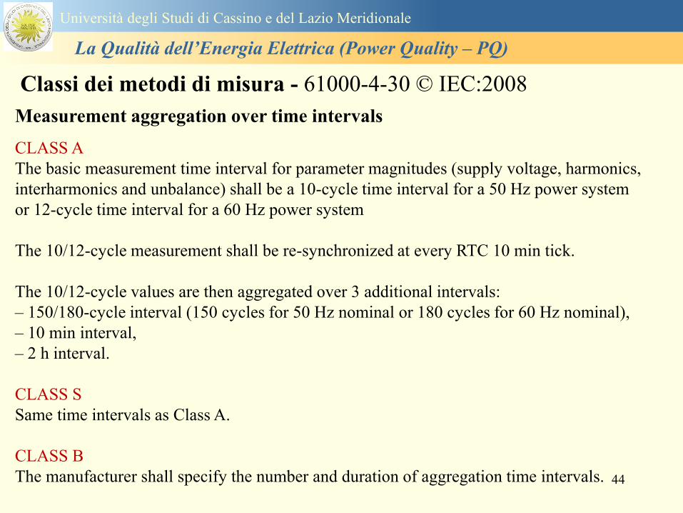
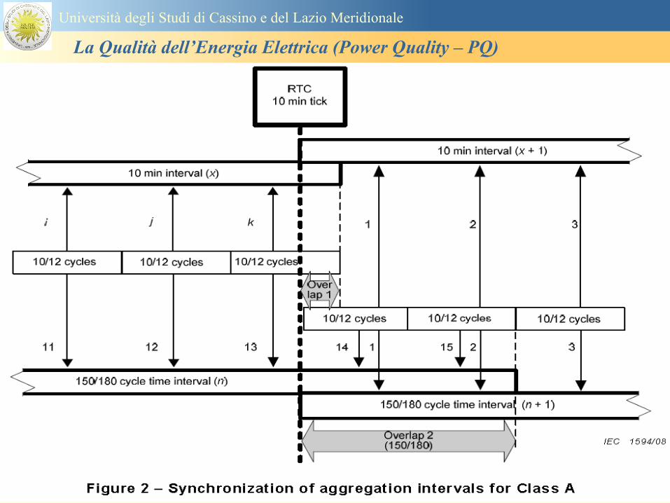
45
Universitagrave degli Studi di Cassino e del Lazio Meridionale
La Qualitagrave dellrsquoEnergia Elettrica (Power Quality ndash PQ)
46
Universitagrave degli Studi di Cassino e del Lazio Meridionale
La Qualitagrave dellrsquoEnergia Elettrica (Power Quality ndash PQ)
Class A
The 10-min aggregated value shall be tagged with the absolute time (for
example 01H1000) The time tag is the time at the conclusion of the 10-min
aggregation
The data for the 10-min time interval shall be aggregated from 1012-cycle time
intervals
Each 10-minute interval shall begin on a UTC 10-min tick The 10-min tick is
also used to re-synchronize the 1012-cycle intervals and the 150180-cycle
intervals
The final 1012-cycle interval(s) in a 10-min aggregation period will typically
overlap in time with the UTC 10-min clock tick Any overlapping 1012-cycle
interval (Overlap 1 in Figure 2) is included in the aggregation of the previous
10-min interval
47
Universitagrave degli Studi di Cassino e del Lazio Meridionale
La Qualitagrave dellrsquoEnergia Elettrica (Power Quality ndash PQ)
48
Universitagrave degli Studi di Cassino e del Lazio Meridionale
La Qualitagrave dellrsquoEnergia Elettrica (Power Quality ndash PQ)
49
Classi dei metodi di misura - 61000-4-30 copy IEC2008
Real time clock (RTC) uncertainty
Sono definite le specifiche per le 3 classi
Flagging concept
During a dip swell or interruption the measurement algorithm for other
parameters (for example frequency measurement) might produce an unreliable
value The flagging concept therefore avoids counting a single event more than
once in different parameters (for example counting a single dip as both a dip and a
frequency variation) and indicates that an aggregated value might be unreliable
Universitagrave degli Studi di Cassino e del Lazio Meridionale
La Qualitagrave dellrsquoEnergia Elettrica (Power Quality ndash PQ)
50
Classi dei metodi di misura - 61000-4-30 copy IEC2008
Power quality parameters - INDICES
Per ogni parametro viene suggerito il metodo di misura per le tre classi e
(soprattutto) le caratteristiche di precisione Per alcuni parametri rimanda a
specifiche norme (ad esempio Flicker e Armonicheinterarmoniche)
Esempio - Power frequency Class A
The frequency reading shall be obtained every 10 s As power frequency may not be exactly 50 Hz or 60
Hz within the 10 s time clock interval the number of cycles may not be an integer number The
fundamental frequency output is the ratio of the number of integral cycles counted during the 10 s time
clock interval divided by the cumulative duration of the integer cycles Before each assessment
harmonics and interharmonics shall be attenuated to minimize the effects of multiple zero crossings
The measurement time intervals shall be non-overlapping Individual cycles that overlap the 10 s time
clock are discarded Each 10 s interval shall begin on an absolute 10 s time clock with uncertainty as
defined in 46
Other techniques that provide equivalent results such as convolution are acceptable
Class S Same as class A
Class B The manufacturer shall specify the process used for frequency measurement
Universitagrave degli Studi di Cassino e del Lazio Meridionale
La Qualitagrave dellrsquoEnergia Elettrica (Power Quality ndash PQ)
51
Classi dei metodi di misura - 61000-4-30 copy IEC2008
Power quality parameters - INDICES
Per ogni parametro viene suggerito il metodo di misura per le tre classi e
(soprattutto) le caratteristiche di precisione Per alcuni parametri rimanda a
specifiche norme (ad esempio Flicker e Armonicheinterarmoniche)
Esempio - Power frequency
Measurement uncertainty and measuring range
ndash Class A
Under the conditions described in 61 the measurement uncertainty shall not exceed
plusmn10 mHz over the measuring ranges 425 Hz ~ 575 Hz 51 Hz ~ 69 Hz
ndash Class S
Under the conditions described in 61 the measurement uncertainty shall not exceed
plusmn50 mHz over the measuring ranges 425 Hz ~ 575 Hz 51 Hz ~ 69 Hz
ndash Class B
The manufacturer shall specify the uncertainty over the measuring ranges 425 Hz ~
575 Hz 51 Hz ~ 69 Hz
Universitagrave degli Studi di Cassino e del Lazio Meridionale
La Qualitagrave dellrsquoEnergia Elettrica (Power Quality ndash PQ)
52
Magnitude of the supply voltage
Measurement method
ndash Class A
The measurement shall be the rms value of the voltage magnitude over
a 10-cycle time interval for 50 Hz power system or 12-cycle time
interval for 60 Hz power system Every 1012-cycle interval shall be
contiguous and not overlapping with adjacent 1012-cycle intervals
except as shown as Overlap 1 in Figure 2
NOTE 1 This specific measurement method is used for quasi-stationary signals and is
not used for the detection and measurement of disturbances dips swells voltage
interruptions and transients
NOTE 2 The rms value includes by definition harmonics interharmonics mains
signalling etc
- Class S same as Class A
Universitagrave degli Studi di Cassino e del Lazio Meridionale
La Qualitagrave dellrsquoEnergia Elettrica (Power Quality ndash PQ)
53
Magnitude of the supply voltage
Measurement uncertainty and measuring range
ndash Class A
Under the conditions described in Clause 6 the measurement uncertainty
shall not exceed plusmn01 of Udin over the range of 10 ~ 150 of Udin
ndash Class S
Under the conditions described in Clause 6 the measurement uncertainty
shall not exceed plusmn05 of Udin over the range of 20 ~ 120 of Udin
Universitagrave degli Studi di Cassino e del Lazio Meridionale
La Qualitagrave dellrsquoEnergia Elettrica (Power Quality ndash PQ)
54
Supply voltage dips and swells
Measurement method
ndash Class A
The basic measurement Urms of a voltage dip and swell shall be the
Urms(frac12) on each measurement channel (see Clause 322)
The cycle duration for Urms(frac12) depends on the frequency The
frequency might be determined by the last non-flagged power frequency
measurement (see Clause 47 and Clause 51) or by any other method
that yields the uncertainty requirements of Clause 6
NOTE 1 The Urms(frac12) value includes by definition harmonics interharmonics mains
signalling voltage etc
NOTE 2 It is important to avoid loss of data when dips and swells occur in a rapid
sequence (for example three events in one second with up to one minute between
sequences may occur when a recloser operates into a sustained fault) If during a rapid
burst the dipswell event characteristics cannot be recorded then a count of events may
be useful
Universitagrave degli Studi di Cassino e del Lazio Meridionale
La Qualitagrave dellrsquoEnergia Elettrica (Power Quality ndash PQ)
55
Supply voltage dips and swells
Detection and evaluation of a voltage dip
Voltage dip detection
The dip threshold is a percentage of either Udin or the sliding voltage
reference Usr (see 525 544) The user shall declare the reference
voltage in use
NOTE ndash On single-phase systems a voltage dip begins when the Urms voltage falls
below the dip threshold and ends when the Urms voltage is equal to or above the dip
threshold plus the hysteresis voltage
ndash On polyphase systems a dip begins when the Urms voltage of one or more channels is
below the dip threshold and ends when the Urms voltage on all measured channels is
equal to or above the dip threshold plus the hysteresis voltage
The dip threshold and the hysteresis voltage are both set by the user according to the
use
Universitagrave degli Studi di Cassino e del Lazio Meridionale
La Qualitagrave dellrsquoEnergia Elettrica (Power Quality ndash PQ)
56
Calculation of a sliding reference voltage
The sliding reference voltage implementation is optional not mandatory
If a sliding reference is chosen for voltage dip or swell detection this
shall be calculated using a first-order filter with a 1-min time constant
This filter is given by
Usr(n) = 09967 times Usr(nndash1) + 00033 times U(1012)rms
where
Usr(n) is the present value of the sliding reference voltage
Usr(nndash1) is the previous value of the sliding reference voltage and
U(1012)rms is the most recent 1012-cycle rms value
When the measurement is started the initial value of the sliding reference voltage is set
to the declared input voltage The sliding reference voltage is updated every 1012-
cycles If a 1012-cycle value is flagged the sliding reference voltage is not updated
and the previous value is used
Universitagrave degli Studi di Cassino e del Lazio Meridionale
La Qualitagrave dellrsquoEnergia Elettrica (Power Quality ndash PQ)
57
Supply voltage dips and swells
Voltage dip evaluation
A voltage dip is characterized by a pair of data either residual voltage
(Ures) or depth and duration
ndash the residual voltage of a voltage dip is the lowest Urms(frac12) value
measured on any channel during the dip
ndash the depth is the difference between the reference voltage (either Udin
or Usr) and the residual voltage It is generally expressed in percentage
of the reference voltage
NOTE 1 During the dip it may be useful to also record the lowest Urms(frac12) on each
channel in addition to the residual voltage of the dip The duration spent below the dip
threshold on each channel may also be useful
Universitagrave degli Studi di Cassino e del Lazio Meridionale
La Qualitagrave dellrsquoEnergia Elettrica (Power Quality ndash PQ)
58
Supply voltage dips and swells
Voltage dip evaluation
NOTE 2 If voltage waveforms are recorded before during and after a
dip useful information about phase angle changes may be available in
the recorded data
The start time of a dip shall be time stamped with the time of the start of
the Urms of the channel that initiated the event and the end time of the
dip shall be the time stamped with the time of the end of the Urms that
ended the event as defined by the threshold plus the hysteresis
The duration of a voltage dip is the time difference between the start
time and the end time of the voltage dip
Universitagrave degli Studi di Cassino e del Lazio Meridionale
La Qualitagrave dellrsquoEnergia Elettrica (Power Quality ndash PQ)
59
Supply voltage dips and swells
Residual voltage and swell voltage magnitude measurement
uncertainty
ndash Class A
The measurement uncertainty shall not exceed plusmn02 of Udin
ndash Class S
The measurement uncertainty shall not exceed plusmn10 of Udin
Universitagrave degli Studi di Cassino e del Lazio Meridionale
La Qualitagrave dellrsquoEnergia Elettrica (Power Quality ndash PQ)
60
Schema di principio ndash 61000-4-7 copy IEC2002
Universitagrave degli Studi di Cassino e del Lazio Meridionale
La Qualitagrave dellrsquoEnergia Elettrica (Power Quality ndash PQ)
61
Universitagrave degli Studi di Cassino e del Lazio Meridionale
La Qualitagrave dellrsquoEnergia Elettrica (Power Quality ndash PQ)
62
Universitagrave degli Studi di Cassino e del Lazio Meridionale
La Qualitagrave dellrsquoEnergia Elettrica (Power Quality ndash PQ)
63
Inter-Armoniche Le inter-armoniche sono tensioni o correnti sinusoidali con frequenza diversa da un
multiplo intero della fondamentale la cui presenza determina una distorsione
(modulazione) della forma donda della tensione di alimentazione
CAUSE dai carichi che assorbono correnti inter-armoniche
- carichi commutati elettronicamente convertitori cascata subsincrona cicloconvertitori regolatori con
controllo a pacchetti di cicli ecc
- carichi con caratteristiche non lineari eo non stazionarie forni ad arco saldatrici ad arco ecc
Universitagrave degli Studi di Cassino e del Lazio Meridionale
La Qualitagrave dellrsquoEnergia Elettrica (Power Quality ndash PQ)
64
Universitagrave degli Studi di Cassino e del Lazio Meridionale
La Qualitagrave dellrsquoEnergia Elettrica (Power Quality ndash PQ)
Un porsquo di esempi e
consigli praticihellip
65
0V
50V
100V
150V
200V
250V
300V
350V
0ms 5ms 10ms 15ms 20ms
t
u
0A
1A
2A
3A
i
0V
50V
100V
150V
200V
250V
300V
350V
0ms 5ms 10ms 15ms 20ms
t
u
0A
1A
2A
3A
i
0V
50V
100V
150V
200V
250V
300V
350V
0ms 5ms 10ms 15ms 20ms
t
u
0A
1A
2A
3A
i
gleichgerichtete
Netzspannung
Kondensator-
spannung
gleichgerichteter
Netzstrom
The situation
today
bull Computed current and voltage profiles when a
230 V 58 W fluorescent lamp with an old-style
electronic ballast is driven on the phase wire of
a typical power distribution system
System voltage 230 V
System frequency 50 Hz
Source resistance 500 mW
Longitudinal induction 904 microH
System impedance 575 mW
Mean dc current 180 mA
Smoothing capacitance220 microF
66
And what about electronic ballasts that are rated over 25W
Introduce electronic power factor correction (PFC)
0V
20V
40V
60V
80V
100V
120V
140V
160V
180V
200V
220V
0deg 15deg 30deg 45deg
u
00A
03A
06A
09A
12A
i
67
Though todayrsquos ballasts are better if
rated gt25 W bull Only
the
small
ones
continu
e to
pollute
just like
PCs
TV sets
do
68
This leads to a number of
previously unknown effects bull 1 Deformed voltage curves
bull 2 Huge inrush current peaks
bull 3 Instrument dependent measured parameters
bull 4 Increased loading of phase conductors
bull 5 Loading and overloading of the neutral conductor
bull 6 Overheating and start-up problems of induction motors
bull 7 Additional stray losses in transformers
bull 8 Repercussions of generators upon the mains
bull 9 Influence of capacitors repercussions upon the mains
and four additional complications in TN-C systems
10 Stray currents in equipotential bonding system magnetic fields
11 Contamination of data streams by stray currents
12 Stray currents in the earthing system corrosion damage
13 Lightning currents in devices and equipment
69
1 Deformed voltage curves
bull in theory
-350V
-300V
-250V
-200V
-150V
-100V
-50V
0V
50V
100V
150V
200V
250V
300V
350V
0 5 10 15 20
t ms
u
System voltage profile when driving
a single-phase load comprising
twenty 58 W energy-saver lamps in
parallel on a typical 230 V power
system
70
and in practice
bull An actual
current profile
bull
bull and
bull a voltage profile
bull
bull recorded in a large storage
dispatch and administrative
building
71
at home or in industrial environments
bull
bull Television 40
W
bull 200 Vdiv 2
Adiv
bull 5 msdiv
Harmonic
spectrum
Frequency
converter
50 Adiv
Phase currents
I1=I2=I3=160 A
IN=295 A
5 msdiv
72
Every periodic waveform can be written
as the infinite sum of sinusoidal waves
-175
-150
-125
-100
-75
-50
-25
0
25
50
75
100
125
150
175
0 5 10 15 20
t ms
i
mA
itot
i1
Synthesis of a triangular current profile 100mA
Content fundamental I = 99 mA Isup2 = 9855 mAsup2
Sum of squares Isup2 = 9855 mAsup2
Root of sum = RMS value I = 99 mA
-175
-150
-125
-100
-75
-50
-25
0
25
50
75
100
125
150
175
0 5 10 15 20
t ms
i
mA
itot
i1
i3
Synthesis of a triangular current profile 100mA
Content fundamental I = 99 mA Isup2 = 9855 mAsup2
Cont 3 rd harmonic I = -11 mA Isup2 = 122 mAsup2
Sum of squares Isup2 = 9977 mAsup2
Root of sum = RMS value I = 100 mA
-175
-150
-125
-100
-75
-50
-25
0
25
50
75
100
125
150
175
0 5 10 15 20
t ms
i
mA
itot
i1
i3
i5
Synthesis of a triangular current profile 100mA
Content fundamental I = 99 mA Isup2 = 9855 mAsup2
Cont 3 rd harmonic I = -11 mA Isup2 = 122 mAsup2
Cont 5 th harmonic I = 4 mA Isup2 = 16 mAsup2
Sum of squares Isup2 = 9993 mAsup2
Root of sum = RMS value I = 100 mA
-175
-150
-125
-100
-75
-50
-25
0
25
50
75
100
125
150
175
0 5 10 15 20
t ms
i
mA
itot
i1
i3
i5
i7
Synthesis of a triangular current profile 100mA
Content fundamental I = 99 mA Isup2 = 9855 mAsup2
Cont 3 rd harmonic I = -11 mA Isup2 = 122 mAsup2
Cont 5 th harmonic I = 4 mA Isup2 = 16 mAsup2
Cont 7 th harmonic I = -2 mA Isup2 = 4 mAsup2
Sum of squares Isup2 = 9997 mAsup2
Root of sum = RMS value I = 100 mA
-175
-150
-125
-100
-75
-50
-25
0
25
50
75
100
125
150
175
0 5 10 15 20
t ms
i
mA
itot i1
i3 i5
i7 i9
Synthesis of a triangular current profile 100mA
Content fundamental I = 99 mA Isup2 = 9855 mAsup2
Cont 3 rd harmonic I = -11 mA Isup2 = 122 mAsup2
Cont 5 th harmonic I = 4 mA Isup2 = 16 mAsup2
Cont 7 th harmonic I = -2 mA Isup2 = 4 mAsup2
Cont 9 th harmonic I = 1 mA Isup2 = 2 mAsup2
Sum of squares Isup2 = 9998 mAsup2
Root of sum = RMS value I = 100 mA
-175
-150
-125
-100
-75
-50
-25
0
25
50
75
100
125
150
175
0 5 10 15 20
t ms
i
mA
itot i1
i3 i5
i7 i9
i11
Synthesis of a triangular current profile 100mA
Content fundamental I = 99 mA Isup2 = 9855 mAsup2
Cont 3 rd harmonic I = -11 mA Isup2 = 122 mAsup2
Cont 5 th harmonic I = 4 mA Isup2 = 16 mAsup2
Cont 7 th harmonic I = -2 mA Isup2 = 4 mAsup2
Cont 9 th harmonic I = 1 mA Isup2 = 2 mAsup2
Cont 11 th harmonic I = -1 mA Isup2 = 1 mAsup2
Sum of squares Isup2 = 9999 mAsup2
Root of sum = RMS value I = 100 mA
-175
-150
-125
-100
-75
-50
-25
0
25
50
75
100
125
150
175
0 5 10 15 20
t ms
i
mA
itot i1
i3 i5
i7 i9
i11 i13
Synthesis of a triangular current profile 100mA
Content fundamental I = 99 mA Isup2 = 9855 mAsup2
Cont 3 rd harmonic I = -11 mA Isup2 = 122 mAsup2
Cont 5 th harmonic I = 4 mA Isup2 = 16 mAsup2
Cont 7 th harmonic I = -2 mA Isup2 = 4 mAsup2
Cont 9 th harmonic I = 1 mA Isup2 = 2 mAsup2
Cont 11 th harmonic I = -1 mA Isup2 = 1 mAsup2
Cont 13 th harmonic I = 1 mA Isup2 = 0 mAsup2
Sum of squares Isup2 = 9999 mAsup2
Root of sum = RMS value I = 100 mA
-175
-150
-125
-100
-75
-50
-25
0
25
50
75
100
125
150
175
0 5 10 15 20
t ms
i
mA
itot i1
i3 i5
i7 i9
i11 i13
i15
Synthesis of a triangular current profile 100mA
Content fundamental I = 99 mA Isup2 = 9855 mAsup2
Cont 3 rd harmonic I = -11 mA Isup2 = 122 mAsup2
Cont 5 th harmonic I = 4 mA Isup2 = 16 mAsup2
Cont 7 th harmonic I = -2 mA Isup2 = 4 mAsup2
Cont 9 th harmonic I = 1 mA Isup2 = 2 mAsup2
Cont 11 th harmonic I = -1 mA Isup2 = 1 mAsup2
Cont 13 th harmonic I = 1 mA Isup2 = 0 mAsup2
Cont 15 th harmonic I = 0 mA Isup2 = 0 mAsup2
Sum of squares Isup2 = 10000 mAsup2
Root of sum = RMS value I = 100 mA
-175
-150
-125
-100
-75
-50
-25
0
25
50
75
100
125
150
175
0 5 10 15 20
t ms
i
mA
itot i1
i3 i5
i7 i9
i11 i13
i15 i17
Synthesis of a triangular current profile 100mA
Content fundamental I = 99 mA Isup2 = 9855 mAsup2
Cont 3 rd harmonic I = -11 mA Isup2 = 122 mAsup2
Cont 5 th harmonic I = 4 mA Isup2 = 16 mAsup2
Cont 7 th harmonic I = -2 mA Isup2 = 4 mAsup2
Cont 9 th harmonic I = 1 mA Isup2 = 2 mAsup2
Cont 11 th harmonic I = -1 mA Isup2 = 1 mAsup2
Cont 13 th harmonic I = 1 mA Isup2 = 0 mAsup2
Cont 15 th harmonic I = 0 mA Isup2 = 0 mAsup2
Cont 17 th harmonic I = 0 mA Isup2 = 0 mAsup2
Sum of squares Isup2 = 10000 mAsup2
Root of sum = RMS value I = 100 mA
73
whose frequencies called harmonics are
integer multiples of the fundamental frequency
-175
-150
-125
-100
-75
-50
-25
0
25
50
75
100
125
150
175
0 5 10 15 20
t ms
i
mA
itot
i1
Synthesis of a rectangular current profile 100mA
Content fundamental I = 90 mA Isup2 = 8106 mAsup2
Sum of squares Isup2 = 8106 mAsup2
Root of sum = RMS value I = 90 mA
-175
-150
-125
-100
-75
-50
-25
0
25
50
75
100
125
150
175
0 5 10 15 20
t ms
i
mA
itot
i1
i3
Synthesis of a rectangular current profile 100mA
Content fundamental I = 90 mA Isup2 = 8106 mAsup2
Cont 3 rd harmonic I = 30 mA Isup2 = 901 mAsup2
Sum of squares Isup2 = 9006 mAsup2
Root of sum = RMS value I = 95 mA
-175
-150
-125
-100
-75
-50
-25
0
25
50
75
100
125
150
175
0 5 10 15 20
t ms
i
mA
itot
i1
i3
i5
Synthesis of a rectangular current profile 100mA
Content fundamental I = 90 mA Isup2 = 8106 mAsup2
Cont 3 rd harmonic I = 30 mA Isup2 = 901 mAsup2
Cont 5 th harmonic I = 18 mA Isup2 = 324 mAsup2
Sum of squares Isup2 = 9331 mAsup2
Root of sum = RMS value I = 97 mA
-175
-150
-125
-100
-75
-50
-25
0
25
50
75
100
125
150
175
0 5 10 15 20
t ms
i
mA
itot
i1
i3
i5
i7
Synthesis of a rectangular current profile 100mA
Content fundamental I = 90 mA Isup2 = 8106 mAsup2
Cont 3 rd harmonic I = 30 mA Isup2 = 901 mAsup2
Cont 5 th harmonic I = 18 mA Isup2 = 324 mAsup2
Cont 7 th harmonic I = 13 mA Isup2 = 165 mAsup2
Sum of squares Isup2 = 9496 mAsup2
Root of sum = RMS value I = 97 mA
-175
-150
-125
-100
-75
-50
-25
0
25
50
75
100
125
150
175
0 5 10 15 20
t ms
i
mA
itot i1
i3 i5
i7 i9
Synthesis of a rectangular current profile 100mA
Content fundamental I = 90 mA Isup2 = 8106 mAsup2
Cont 3 rd harmonic I = 30 mA Isup2 = 901 mAsup2
Cont 5 th harmonic I = 18 mA Isup2 = 324 mAsup2
Cont 7 th harmonic I = 13 mA Isup2 = 165 mAsup2
Cont 9 th harmonic I = 10 mA Isup2 = 100 mAsup2
Sum of squares Isup2 = 9596 mAsup2
Root of sum = RMS value I = 98 mA
-175
-150
-125
-100
-75
-50
-25
0
25
50
75
100
125
150
175
0 5 10 15 20
t ms
i
mA
itot i1
i3 i5
i7 i9
i11
Synthesis of a rectangular current profile 100mA
Content fundamental I = 90 mA Isup2 = 8106 mAsup2
Cont 3 rd harmonic I = 30 mA Isup2 = 901 mAsup2
Cont 5 th harmonic I = 18 mA Isup2 = 324 mAsup2
Cont 7 th harmonic I = 13 mA Isup2 = 165 mAsup2
Cont 9 th harmonic I = 10 mA Isup2 = 100 mAsup2
Cont 11 th harmonic I = 8 mA Isup2 = 67 mAsup2
Sum of squares Isup2 = 9663 mAsup2
Root of sum = RMS value I = 98 mA
-175
-150
-125
-100
-75
-50
-25
0
25
50
75
100
125
150
175
0 5 10 15 20
t ms
i
mA
itot i1
i3 i5
i7 i9
i11 i13
Synthesis of a rectangular current profile 100mA
Content fundamental I = 90 mA Isup2 = 8106 mAsup2
Cont 3 rd harmonic I = 30 mA Isup2 = 901 mAsup2
Cont 5 th harmonic I = 18 mA Isup2 = 324 mAsup2
Cont 7 th harmonic I = 13 mA Isup2 = 165 mAsup2
Cont 9 th harmonic I = 10 mA Isup2 = 100 mAsup2
Cont 11 th harmonic I = 8 mA Isup2 = 67 mAsup2
Cont 13 th harmonic I = 7 mA Isup2 = 48 mAsup2
Sum of squares Isup2 = 9711 mAsup2
Root of sum = RMS value I = 99 mA
-175
-150
-125
-100
-75
-50
-25
0
25
50
75
100
125
150
175
0 5 10 15 20
t ms
i
mA
itot i1
i3 i5
i7 i9
i11 i13
i15
Synthesis of a rectangular current profile 100mA
Content fundamental I = 90 mA Isup2 = 8106 mAsup2
Cont 3 rd harmonic I = 30 mA Isup2 = 901 mAsup2
Cont 5 th harmonic I = 18 mA Isup2 = 324 mAsup2
Cont 7 th harmonic I = 13 mA Isup2 = 165 mAsup2
Cont 9 th harmonic I = 10 mA Isup2 = 100 mAsup2
Cont 11 th harmonic I = 8 mA Isup2 = 67 mAsup2
Cont 13 th harmonic I = 7 mA Isup2 = 48 mAsup2
Cont 15 th harmonic I = 6 mA Isup2 = 36 mAsup2
Sum of squares Isup2 = 9747 mAsup2
Root of sum = RMS value I = 99 mA
-175
-150
-125
-100
-75
-50
-25
0
25
50
75
100
125
150
175
0 5 10 15 20
t ms
i
mA
itot i1
i3 i5
i7 i9
i11 i13
i15 i17
Synthesis of a rectangular current profile 100mA
Content fundamental I = 90 mA Isup2 = 8106 mAsup2
Cont 3 rd harmonic I = 30 mA Isup2 = 901 mAsup2
Cont 5 th harmonic I = 18 mA Isup2 = 324 mAsup2
Cont 7 th harmonic I = 13 mA Isup2 = 165 mAsup2
Cont 9 th harmonic I = 10 mA Isup2 = 100 mAsup2
Cont 11 th harmonic I = 8 mA Isup2 = 67 mAsup2
Cont 13 th harmonic I = 7 mA Isup2 = 48 mAsup2
Cont 15 th harmonic I = 6 mA Isup2 = 36 mAsup2
Cont 17 th harmonic I = 5 mA Isup2 = 28 mAsup2
Sum of squares Isup2 = 9775 mAsup2
Root of sum = RMS value I = 99 mA
74
Even far better simulations are
available free of charge at
bull wwwpowerstandardscomMcEachern
75
-4A
-3A
-2A
-1A
0A
1A
2A
3A
4A
0ms 5ms 10ms 15ms 20ms
t
i
-4A
-3A
-2A
-1A
0A
1A
2A
3A
4A
0ms 5ms 10ms 15ms 20ms
t
i
Applying the Fourier
analysis to a real PC
current does not work
directly
bull
bull but it can be
modelled by a similar
triangular curve in
which not all of the
higher harmonics
have been included
Triangular current profile of
the same amplitude and a
pulse duty cycle of 17
Input current of a PC
with monitor
76
Analysis of the model triangular waveform
-400
-350
-300
-250
-200
-150
-100
-50
0
50
100
150
200
250
300
350
400
0 5 10 15 20
t ms
iI
itot(t) L1 [A] i1(t) L1 [A]
i3(t) L1 [A] i5(t) L1 [A]
i7(t) L1 [A] i9(t) L1 [A]
i11(t) L1 [A] i13(t) L1 [A]
i15(t) L1 [A] i17(t) L1 [A]
77
M3
Harmonics
Energy
(active
power)
L1
L2
L3
N
PE
Important
bull Harmonics are created within the loads
themselves and can flow ldquoupstreamrdquo to
contaminate the power system
78
-6A
-5A
-4A
-3A
-2A
-1A
0A
1A
2A
3A
4A
5A
6A
0ms 5ms 10ms 15ms 20ms
t
i
Squared values
Without
Fundamental 502 mA 251986 mAsup2 the fundamental
3rd harmonic -479 mA 229000 mAsup2 229000 mAsup2
5th harmonic 434 mA 188595 mAsup2 188595 mAsup2
7th harmonic -374 mA 139903 mAsup2 139903 mAsup2
9th harmonic 304 mA 92527 mAsup2 92527 mAsup2
11th harmonic -232 mA 53671 mAsup2 53671 mAsup2
13th harmonic 163 mA 26600 mAsup2 26600 mAsup2
15th harmonic -104 mA 10780 mAsup2 10780 mAsup2
17th harmonic 57 mA 3299 mAsup2 3299 mAsup2
Sum of the squares 996362 mAsup2 744377 mAsup2
Root thereof 998 mAeff THD = 863 mA
What actually is THD Example shown here triangular current
profile with an rms current of 1000 mA
and a pulse duty cycle of 17
THDr (root mean square) = 863mA1000mA = 86
THDf (fundamental) = 863mA502mA = 172
79
Effect on phase-to-neutral
and phase-to-phase voltages
bull Recorded
on June
30 2002
230 p
m
bull What
was the
matter
then
bull The
soccer
final
Germany
vs
Brazil
80
The triple-N harmonics drive
a circulating current in the
delta winding of a distribution
transformer
bull but the
bull voltage harmonics
propagate into the next
low-voltage power
distribution system
81 0V
50V
100V
150V
200V
250V
300V
350V
400V
450V
500V
550V
0 10 20 30 40 50
t ms
u
0A
10A
20A
30A
40A
50A
60A
70A
80A
90A
100A
110A
120A
130A
140A
150A
i
Switching on just as supply voltage passes through zero
0V
50V
100V
150V
200V
250V
300V
350V
400V
450V
500V
550V
0 10 20 30 40 50
t ms
u
0A
10A
20A
30A
40A
50A
60A
70A
80A
90A
100A
110A
120A
130A
140A
150A
i
Switching on just as supply voltage is at its peak
2 Huge inrush current peaks
ndash in theory
82
and in practice
bull Inrush current of a
compact energy-
saver lamp and its
effect on the system
voltage (recorded at
the Technical
University of
Budapest)
bull
83
enables us to infer what
happens when run by a
normal three-phase supply
The same fluorescent lamp
with a magnetic ballast
bull The behaviour measured
when connected to
a dc supply
bull
Behaviour of a 58 W fluorescent lamp connected to a dc
supply
0
20
40
60
80
100
120
140
160
180
200
0 200 400 600 800 1000 1200
i mA
u
V
Measurement
Behaviour of a 58 W fluorescent lamp connected to a dc
supply
0
20
40
60
80
100
120
140
160
180
200
0 200 400 600 800 1000 1200
i mA
u
V
MeasurementCalculation
-350
-300
-250
-200
-150
-100
-50
0
50
100
150
200
250
300
350
0 5 10 15 20
t ms
u
V
-10
-08
-06
-04
-02
00
02
04
06
08
10
i
A
Systems voltage
Current
-350
-300
-250
-200
-150
-100
-50
0
50
100
150
200
250
300
350
0 5 10 15 20
t ms
u
V
-10
-08
-06
-04
-02
00
02
04
06
08
10
i
A
Systems voltage
Lamp voltage
Current
84
Warning ldquoCompensationrdquo is not
always what you think it is
bull Distinguish
between
bull Reactive
power
compensatio
n
aka power
factor
correction
Remedial
measure
Parallel (or
sometimes series)
compensation
using capacitors
Filter circuits
tuned to the
individual harmonic
frequencies
Harmonic
compensation
85
5 (Over)loading the neutral conductor
bull Magnetic ballast Old-style electronic ballast
-25A
-20A
-15A
-10A
-05A
00A
05A
10A
15A
20A
25A
0 5 10 15 20
t ms i
i(t) N
-25A
-20A
-15A
-10A
-05A
00A
05A
10A
15A
20A
25A
0 5 10 15 20
t ms
i
i(t) N
-25A
-20A
-15A
-10A
-05A
00A
05A
10A
15A
20A
25A
0 5 10 15 20
t ms
i
i(t) L1 i(t) L2 i(t) L3
-25A
-20A
-15A
-10A
-05A
00A
05A
10A
15A
20A
25A
0 5 10 15 20
t ms
i
i(t) L1
i(t) L2
i(t) L3
86
Adding the 3rd
harmonics
in the
neutral
wire
-150-100-50
050
100150
0deg 30deg 60deg 90deg 120deg 150deg 180deg 210deg 240deg 270deg 300deg 330deg 360deg
L1
-150-100-50
050
100150
0deg 30deg 60deg 90deg 120deg 150deg 180deg 210deg 240deg 270deg 300deg 330deg 360deg
L2
-150-100-50
050
100150
0deg 30deg 60deg 90deg 120deg 150deg 180deg 210deg 240deg 270deg 300deg 330deg 360deg
L3
-450-400-350-300-250-200-150-100-50
050
100150200250300350400450
0deg 30deg 60deg 90deg 120deg 150deg 180deg 210deg 240deg 270deg 300deg 330deg 360deg
f
iicirc
N
Physics dictates
that at any
moment in time
the phase and
neutral currents
must sum to zero
87
Effect on a three-phase ac motor
appears almost identical
bull The same motor is being
driven
simultaneously in
these three modes
homopolar system
zero-sequence system
direct system
positive-sequence system
inverse system
negative-sequence system
88
The transformer
influences the load
89
but the load also effects
the transformer
Total transformer loss is
2
)()(
nom
nomCunomFeLossI
IPPP
While total transformer loss really is
2
)(
2
)(
2
)(
nomnom
nomad
nom
nomCu
nom
nomFeLossI
I
f
fP
I
IP
U
UPP
90
6 ldquosupplementaryrdquo additional losses
in transformers
can be calculated rapidly
using the following two
simple formulae 50
2
2
1
2
11
Nn
n
nqh
I
In
I
I
e
eK
50
1
2
1
1
50
1
2
Nn
n
nNn
n
nI
IIII
where
Oh well
perhaps a practical
example is clearer
1000 compact 11W
(15VA) energy-saver
lamps powered by a
15kVA transformer
uSC=4 Pa=01PCu
Harmonics of an Osram Dulux 11W
CFL and a serial impedance of
R =291Ω amp X L=113Ω
U U sup2 I L I Lsup2 P aP Cu
n V Vsup2 mA mAsup2
1 2302 529920 485 23523 56
3 83 689 371 13764 295
5 107 1145 203 4121 245
7 43 185 53 281 33
9 11 12 30 90 17
11 23 53 38 144 42
13 10 10 15 23 09
15 06 04 15 23 12
17 11 12 15 23 15
19 05 03 09 08 07
21 05 03 13 17 18
23 06 04 08 06 08
25 04 02 06 04 05
27 06 04 08 06 11
29 04 02 05 03 05
31 03 01 05 03 06
33 03 01 05 03 06
35 03 01 04 02 05
37 03 01 04 02 05
39 03 01 03 01 03
41 01 00 03 01 04
43 02 00 02 00 02
45 01 00 02 00 02
47 01 00 02 00 02
49 01 00 01 00 01
51 01 00 01 00 01
P aP Cu = 814814
etc
etc
91
Harmonics measurement on an
Osram Dulux 11W compact
fluorescent lamp
U U sup2 I L I Lsup2 P addP Cu
n V Vsup2 mA mAsup2
1 2327 541493 489 23912 37
3 06 04 391 15288 215
5 44 194 264 6970 273
7 23 53 200 4000 307
9 01 00 192 3686 467
11 01 00 166 2756 522
13 01 00 127 1613 427
15 01 00 110 1210 426
17 01 00 102 1040 471
19 01 00 87 757 428
21 01 00 77 593 409
23 01 00 73 533 441
25 01 00 61 372 364
27 01 00 49 240 274
29 01 00 42 176 232
31 01 00 36 130 195
33 01 00 30 90 153
35 01 00 33 109 209
37 01 00 31 96 206
39 01 00 25 63 149
41 01 00 25 63 164
43 01 00 25 63 181
45 01 00 19 36 114
47 01 00 18 32 112
49 01 00 19 36 136
51 01 00 16 26 104
P aP Cu = 7017
To some extent
the transformer
protects itself
bull Always remember to
consider it
bull If the influence of the
transformer upon the load
did not exist then the
influence of the load upon
the transformer would be
nearly 9 times as high
7017
etc
etc
92
Rule of thumb Select transformers 35
larger than specification by apparent
power would require
bull This suffices to err
on the safe side
even in the worst
case and can
hardly ever be
wrong since
maximum
efficiency always
lies between 25
and 50 of rated
load
Efficiency of a 1 MVA transformer plotted against loading
985
986
987
988
989
990
991
992
993
994
0 25 50 75 100 125
Relative load h
Design with max Cu loss and min Fe loss
Design with min Cu loss and max Fe loss
1 MVA oil transformer according to HD 428
93
Measured response of an 11 W
fluorescent lamp operated with a
magnetic ballast
94
We are
dealing with
a complex
problem
bull These
effects
are not
isolated
but are
mutuall
y inter-
depende
nt
Effects 2 3 and 5 can be demonstrated
on DKIrsquos display panel
95
A conventional approximately resistive-
inductive load
mA
N L1 L2 L3
Two conventional approximately
resistive-inductive loads Three conventional approximately
resistive-inductive loads
96
A modern electronic load
mA
N
Two modern electronic loads Three modern electronic loads
L1 L2 L3
97
Discoveries on a
refurbished
junction box
System voltage
(as trigger
signal)
Current in the
earthing
conductor
between the
consumer unit
and the
bonding
busbar
98
The TN-C system that was perfectly
adequate some years ago is unable to meet
present-day requirements
-6
-4
-2
0
2
4
6
0 5 10 15 20
t ms
i
A
-350
-300
-250
-200
-150
-100
-50
0
50
100
150
200
250
300
350
0 5 10 15 20
t ms
u
V
99
ldquoTHFrdquo
(third harmonic
filter) made in
Finland
In certain situations this affordable
filter can be of help
German
version ldquoTHXrdquo
100
0Ω
5 Ω
1 0 Ω
1 5 Ω
2 0 Ω
2 5 Ω
3 0 Ω
3 5 Ω
4 0 Ω
0Hz 50Hz 100Hz 150Hz 200Hz 250Hz 300Hz
f
Z
-90deg
-75deg
-60deg
-45deg
-30deg
-15deg
0deg
15deg
30deg
45deg
60deg
75deg
90deg
φ
Reactorreactance
Capacitorreactance
Parallelimpedace
Phase angle
Data and frequency response
of the filter
bull 1320 microF
bull 875
14 mW microH
101
The filter in use
bull In a nursery running sodium vapour lamps (500 kW)
In a typical office and administrative building
102
The EMC Transformer from Switzerland
7 The effects of stray magnetic fields
in TN-C systems
bull ldquoWhen we build transformers the first thing we focus on is complying with our customersrsquo
requirements and only then on complying with standards Why Because it is customer
needs and not standards that offer real scope for product innovationrdquo
103
8 In a TN-C system problems arise from data
streams and working currents mixing
bull Others who
have drawn
attention to
this source of
data
transmission
errors include
engineering
and insurance
companies experts
consultants and many
others besides
104
9 Increased corrosive damage
bull This (once) galvanized steel strip ndash the earth
electrode of a TN-C-S system ndash was located close
to the transformer station
Side facing
transformer
station
Side facing
transformer
station
Side facing away
from transformer
station
Side facing away
from transformer
station
105
bull WRONG RIGHT
Working currents have no place
in earthing systems and
protective conductors
106
10 Lightning currents
107
Which bridge to
cross which bridge to
burn
Sometimes you just donlsquot
believe what you see
This one will soon
look rather charred
IEC 60364-5-54
54343 If from any point of the installation the neutral and protective
functions are provided by separate conductors it is not permitted to
connect the neutral conductor to any other earthed part of the
installation
108
Well then the rest is no longer a
miracle
109
110
111
Another means of (over)loading the
neutral conductor
bull dc currents
Original ldquoFakerdquo
112
and their
effects U = 2285 V
I = 92 mA
P = 182 W
S = 209 VA
Q = 103 VAr
LF = 087
cos φ = 099
U = 2243 V
I = 126 A
P = 380 W
S = 2860 VA
Q = 2830 VAr
No-load current in a
toroidal-core
transformer
200 VA
-350-300
-250-200
-150-100
-500
50
100150
200250
300350
0 10 20 30 40
t ms
u
V
-12
-10
-8
-6
-4
-2
0
2
4
6
8
10
12
i
mA
Voltage
Current
No-load current in a toroidal-core
transformer 200 VA when
running a 1500 W
hairdryer at
half-power
in parallel
-350-300
-250-200
-150-100
-500
50
100150
200250
300350
0 5 10 15 20 25 30 35 40
t ms
u
V
-6
-5
-4
-3
-2
-1
0
1
2
3
4
5
6
i
A
Voltage
Current
113
The later models donlsquot do it any more
The EN 61000-3-2 has at least managed
to put an end to this approach
Domestic appliances Max 105 A of 2nd harmonic
114
An electrical engineering wonder
dc current generates ac voltage
115
Spicing things up with a pinch of HF
electronic halogen lamp transformers
116
Decorative HF reactors
117
Current and power loss as a function of voltage
00
02
04
06
08
10
12
14
16
18
0 40 80 120 160 200 240
U V
I
A
0
20
40
60
80
100
120
PV
W
I [A]
Pv [W]
Power loss capacitor voltage
and total voltage as a function of current
0
50
100
150
200
250
300
350
400
450
000 025 050 075 100 125 150
I A
U
V
0
5
10
15
20
25
30
35
40
45
50
PV
W
Utot [V] Eff
UR [V] Eff
Pv [W]
The passive
harmonic filter
made of readily
available
components
bull is both
reliable
118
and effective
bull befor
e
bull after
119
Half the solution has already been implemented
120
And if thatrsquos not enough
bull Passive filter circuits will do it
121
So what do we need to do
bull In low-voltage power distribution systems
Do not use cables in which the neutral or protective earth conductor has a
reduced cross-section
Use only 5-core cable Do not install TN-C- or TN-C-S systems
Be generous when dimensioning conductor cross-sections This helps to
reduce line voltage drops and thus reduces the effect of current distortions on
the voltage as well as lowering energy losses (see VDE 0298 Part 100)
Generously dimensioned conductors will have no problem coping with any
future increase in demand
Only use measuring instruments that display the true root mean square value
(TRMS meters)
In medium-voltage power distribution systems
Use a varied mix of distribution transformers with different vector groups
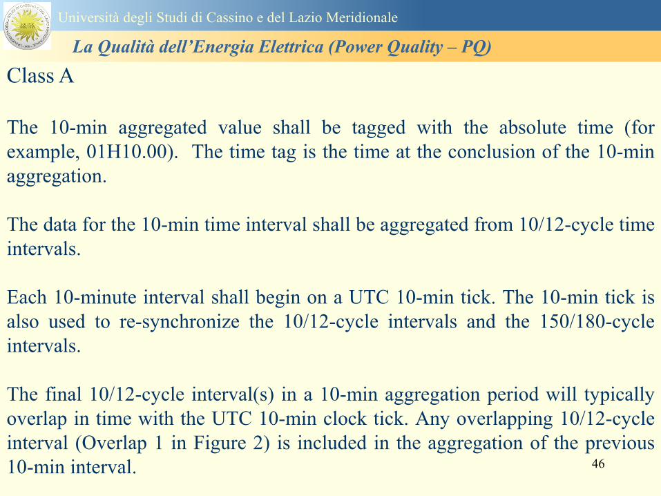
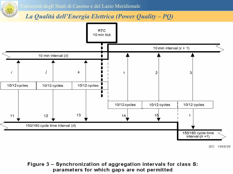
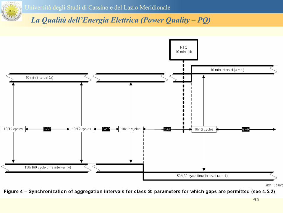
50
Classi dei metodi di misura - 61000-4-30 copy IEC2008
Power quality parameters - INDICES
Per ogni parametro viene suggerito il metodo di misura per le tre classi e
(soprattutto) le caratteristiche di precisione Per alcuni parametri rimanda a
specifiche norme (ad esempio Flicker e Armonicheinterarmoniche)
Esempio - Power frequency Class A
The frequency reading shall be obtained every 10 s As power frequency may not be exactly 50 Hz or 60
Hz within the 10 s time clock interval the number of cycles may not be an integer number The
fundamental frequency output is the ratio of the number of integral cycles counted during the 10 s time
clock interval divided by the cumulative duration of the integer cycles Before each assessment
harmonics and interharmonics shall be attenuated to minimize the effects of multiple zero crossings
The measurement time intervals shall be non-overlapping Individual cycles that overlap the 10 s time
clock are discarded Each 10 s interval shall begin on an absolute 10 s time clock with uncertainty as
defined in 46
Other techniques that provide equivalent results such as convolution are acceptable
Class S Same as class A
Class B The manufacturer shall specify the process used for frequency measurement
Universitagrave degli Studi di Cassino e del Lazio Meridionale
La Qualitagrave dellrsquoEnergia Elettrica (Power Quality ndash PQ)
51
Classi dei metodi di misura - 61000-4-30 copy IEC2008
Power quality parameters - INDICES
Per ogni parametro viene suggerito il metodo di misura per le tre classi e
(soprattutto) le caratteristiche di precisione Per alcuni parametri rimanda a
specifiche norme (ad esempio Flicker e Armonicheinterarmoniche)
Esempio - Power frequency
Measurement uncertainty and measuring range
ndash Class A
Under the conditions described in 61 the measurement uncertainty shall not exceed
plusmn10 mHz over the measuring ranges 425 Hz ~ 575 Hz 51 Hz ~ 69 Hz
ndash Class S
Under the conditions described in 61 the measurement uncertainty shall not exceed
plusmn50 mHz over the measuring ranges 425 Hz ~ 575 Hz 51 Hz ~ 69 Hz
ndash Class B
The manufacturer shall specify the uncertainty over the measuring ranges 425 Hz ~
575 Hz 51 Hz ~ 69 Hz
Universitagrave degli Studi di Cassino e del Lazio Meridionale
La Qualitagrave dellrsquoEnergia Elettrica (Power Quality ndash PQ)
52
Magnitude of the supply voltage
Measurement method
ndash Class A
The measurement shall be the rms value of the voltage magnitude over
a 10-cycle time interval for 50 Hz power system or 12-cycle time
interval for 60 Hz power system Every 1012-cycle interval shall be
contiguous and not overlapping with adjacent 1012-cycle intervals
except as shown as Overlap 1 in Figure 2
NOTE 1 This specific measurement method is used for quasi-stationary signals and is
not used for the detection and measurement of disturbances dips swells voltage
interruptions and transients
NOTE 2 The rms value includes by definition harmonics interharmonics mains
signalling etc
- Class S same as Class A
Universitagrave degli Studi di Cassino e del Lazio Meridionale
La Qualitagrave dellrsquoEnergia Elettrica (Power Quality ndash PQ)
53
Magnitude of the supply voltage
Measurement uncertainty and measuring range
ndash Class A
Under the conditions described in Clause 6 the measurement uncertainty
shall not exceed plusmn01 of Udin over the range of 10 ~ 150 of Udin
ndash Class S
Under the conditions described in Clause 6 the measurement uncertainty
shall not exceed plusmn05 of Udin over the range of 20 ~ 120 of Udin
Universitagrave degli Studi di Cassino e del Lazio Meridionale
La Qualitagrave dellrsquoEnergia Elettrica (Power Quality ndash PQ)
54
Supply voltage dips and swells
Measurement method
ndash Class A
The basic measurement Urms of a voltage dip and swell shall be the
Urms(frac12) on each measurement channel (see Clause 322)
The cycle duration for Urms(frac12) depends on the frequency The
frequency might be determined by the last non-flagged power frequency
measurement (see Clause 47 and Clause 51) or by any other method
that yields the uncertainty requirements of Clause 6
NOTE 1 The Urms(frac12) value includes by definition harmonics interharmonics mains
signalling voltage etc
NOTE 2 It is important to avoid loss of data when dips and swells occur in a rapid
sequence (for example three events in one second with up to one minute between
sequences may occur when a recloser operates into a sustained fault) If during a rapid
burst the dipswell event characteristics cannot be recorded then a count of events may
be useful
Universitagrave degli Studi di Cassino e del Lazio Meridionale
La Qualitagrave dellrsquoEnergia Elettrica (Power Quality ndash PQ)
55
Supply voltage dips and swells
Detection and evaluation of a voltage dip
Voltage dip detection
The dip threshold is a percentage of either Udin or the sliding voltage
reference Usr (see 525 544) The user shall declare the reference
voltage in use
NOTE ndash On single-phase systems a voltage dip begins when the Urms voltage falls
below the dip threshold and ends when the Urms voltage is equal to or above the dip
threshold plus the hysteresis voltage
ndash On polyphase systems a dip begins when the Urms voltage of one or more channels is
below the dip threshold and ends when the Urms voltage on all measured channels is
equal to or above the dip threshold plus the hysteresis voltage
The dip threshold and the hysteresis voltage are both set by the user according to the
use
Universitagrave degli Studi di Cassino e del Lazio Meridionale
La Qualitagrave dellrsquoEnergia Elettrica (Power Quality ndash PQ)
56
Calculation of a sliding reference voltage
The sliding reference voltage implementation is optional not mandatory
If a sliding reference is chosen for voltage dip or swell detection this
shall be calculated using a first-order filter with a 1-min time constant
This filter is given by
Usr(n) = 09967 times Usr(nndash1) + 00033 times U(1012)rms
where
Usr(n) is the present value of the sliding reference voltage
Usr(nndash1) is the previous value of the sliding reference voltage and
U(1012)rms is the most recent 1012-cycle rms value
When the measurement is started the initial value of the sliding reference voltage is set
to the declared input voltage The sliding reference voltage is updated every 1012-
cycles If a 1012-cycle value is flagged the sliding reference voltage is not updated
and the previous value is used
Universitagrave degli Studi di Cassino e del Lazio Meridionale
La Qualitagrave dellrsquoEnergia Elettrica (Power Quality ndash PQ)
57
Supply voltage dips and swells
Voltage dip evaluation
A voltage dip is characterized by a pair of data either residual voltage
(Ures) or depth and duration
ndash the residual voltage of a voltage dip is the lowest Urms(frac12) value
measured on any channel during the dip
ndash the depth is the difference between the reference voltage (either Udin
or Usr) and the residual voltage It is generally expressed in percentage
of the reference voltage
NOTE 1 During the dip it may be useful to also record the lowest Urms(frac12) on each
channel in addition to the residual voltage of the dip The duration spent below the dip
threshold on each channel may also be useful
Universitagrave degli Studi di Cassino e del Lazio Meridionale
La Qualitagrave dellrsquoEnergia Elettrica (Power Quality ndash PQ)
58
Supply voltage dips and swells
Voltage dip evaluation
NOTE 2 If voltage waveforms are recorded before during and after a
dip useful information about phase angle changes may be available in
the recorded data
The start time of a dip shall be time stamped with the time of the start of
the Urms of the channel that initiated the event and the end time of the
dip shall be the time stamped with the time of the end of the Urms that
ended the event as defined by the threshold plus the hysteresis
The duration of a voltage dip is the time difference between the start
time and the end time of the voltage dip
Universitagrave degli Studi di Cassino e del Lazio Meridionale
La Qualitagrave dellrsquoEnergia Elettrica (Power Quality ndash PQ)
59
Supply voltage dips and swells
Residual voltage and swell voltage magnitude measurement
uncertainty
ndash Class A
The measurement uncertainty shall not exceed plusmn02 of Udin
ndash Class S
The measurement uncertainty shall not exceed plusmn10 of Udin
Universitagrave degli Studi di Cassino e del Lazio Meridionale
La Qualitagrave dellrsquoEnergia Elettrica (Power Quality ndash PQ)
60
Schema di principio ndash 61000-4-7 copy IEC2002
Universitagrave degli Studi di Cassino e del Lazio Meridionale
La Qualitagrave dellrsquoEnergia Elettrica (Power Quality ndash PQ)
61
Universitagrave degli Studi di Cassino e del Lazio Meridionale
La Qualitagrave dellrsquoEnergia Elettrica (Power Quality ndash PQ)
62
Universitagrave degli Studi di Cassino e del Lazio Meridionale
La Qualitagrave dellrsquoEnergia Elettrica (Power Quality ndash PQ)
63
Inter-Armoniche Le inter-armoniche sono tensioni o correnti sinusoidali con frequenza diversa da un
multiplo intero della fondamentale la cui presenza determina una distorsione
(modulazione) della forma donda della tensione di alimentazione
CAUSE dai carichi che assorbono correnti inter-armoniche
- carichi commutati elettronicamente convertitori cascata subsincrona cicloconvertitori regolatori con
controllo a pacchetti di cicli ecc
- carichi con caratteristiche non lineari eo non stazionarie forni ad arco saldatrici ad arco ecc
Universitagrave degli Studi di Cassino e del Lazio Meridionale
La Qualitagrave dellrsquoEnergia Elettrica (Power Quality ndash PQ)
64
Universitagrave degli Studi di Cassino e del Lazio Meridionale
La Qualitagrave dellrsquoEnergia Elettrica (Power Quality ndash PQ)
Un porsquo di esempi e
consigli praticihellip
65
0V
50V
100V
150V
200V
250V
300V
350V
0ms 5ms 10ms 15ms 20ms
t
u
0A
1A
2A
3A
i
0V
50V
100V
150V
200V
250V
300V
350V
0ms 5ms 10ms 15ms 20ms
t
u
0A
1A
2A
3A
i
0V
50V
100V
150V
200V
250V
300V
350V
0ms 5ms 10ms 15ms 20ms
t
u
0A
1A
2A
3A
i
gleichgerichtete
Netzspannung
Kondensator-
spannung
gleichgerichteter
Netzstrom
The situation
today
bull Computed current and voltage profiles when a
230 V 58 W fluorescent lamp with an old-style
electronic ballast is driven on the phase wire of
a typical power distribution system
System voltage 230 V
System frequency 50 Hz
Source resistance 500 mW
Longitudinal induction 904 microH
System impedance 575 mW
Mean dc current 180 mA
Smoothing capacitance220 microF
66
And what about electronic ballasts that are rated over 25W
Introduce electronic power factor correction (PFC)
0V
20V
40V
60V
80V
100V
120V
140V
160V
180V
200V
220V
0deg 15deg 30deg 45deg
u
00A
03A
06A
09A
12A
i
67
Though todayrsquos ballasts are better if
rated gt25 W bull Only
the
small
ones
continu
e to
pollute
just like
PCs
TV sets
do
68
This leads to a number of
previously unknown effects bull 1 Deformed voltage curves
bull 2 Huge inrush current peaks
bull 3 Instrument dependent measured parameters
bull 4 Increased loading of phase conductors
bull 5 Loading and overloading of the neutral conductor
bull 6 Overheating and start-up problems of induction motors
bull 7 Additional stray losses in transformers
bull 8 Repercussions of generators upon the mains
bull 9 Influence of capacitors repercussions upon the mains
and four additional complications in TN-C systems
10 Stray currents in equipotential bonding system magnetic fields
11 Contamination of data streams by stray currents
12 Stray currents in the earthing system corrosion damage
13 Lightning currents in devices and equipment
69
1 Deformed voltage curves
bull in theory
-350V
-300V
-250V
-200V
-150V
-100V
-50V
0V
50V
100V
150V
200V
250V
300V
350V
0 5 10 15 20
t ms
u
System voltage profile when driving
a single-phase load comprising
twenty 58 W energy-saver lamps in
parallel on a typical 230 V power
system
70
and in practice
bull An actual
current profile
bull
bull and
bull a voltage profile
bull
bull recorded in a large storage
dispatch and administrative
building
71
at home or in industrial environments
bull
bull Television 40
W
bull 200 Vdiv 2
Adiv
bull 5 msdiv
Harmonic
spectrum
Frequency
converter
50 Adiv
Phase currents
I1=I2=I3=160 A
IN=295 A
5 msdiv
72
Every periodic waveform can be written
as the infinite sum of sinusoidal waves
-175
-150
-125
-100
-75
-50
-25
0
25
50
75
100
125
150
175
0 5 10 15 20
t ms
i
mA
itot
i1
Synthesis of a triangular current profile 100mA
Content fundamental I = 99 mA Isup2 = 9855 mAsup2
Sum of squares Isup2 = 9855 mAsup2
Root of sum = RMS value I = 99 mA
-175
-150
-125
-100
-75
-50
-25
0
25
50
75
100
125
150
175
0 5 10 15 20
t ms
i
mA
itot
i1
i3
Synthesis of a triangular current profile 100mA
Content fundamental I = 99 mA Isup2 = 9855 mAsup2
Cont 3 rd harmonic I = -11 mA Isup2 = 122 mAsup2
Sum of squares Isup2 = 9977 mAsup2
Root of sum = RMS value I = 100 mA
-175
-150
-125
-100
-75
-50
-25
0
25
50
75
100
125
150
175
0 5 10 15 20
t ms
i
mA
itot
i1
i3
i5
Synthesis of a triangular current profile 100mA
Content fundamental I = 99 mA Isup2 = 9855 mAsup2
Cont 3 rd harmonic I = -11 mA Isup2 = 122 mAsup2
Cont 5 th harmonic I = 4 mA Isup2 = 16 mAsup2
Sum of squares Isup2 = 9993 mAsup2
Root of sum = RMS value I = 100 mA
-175
-150
-125
-100
-75
-50
-25
0
25
50
75
100
125
150
175
0 5 10 15 20
t ms
i
mA
itot
i1
i3
i5
i7
Synthesis of a triangular current profile 100mA
Content fundamental I = 99 mA Isup2 = 9855 mAsup2
Cont 3 rd harmonic I = -11 mA Isup2 = 122 mAsup2
Cont 5 th harmonic I = 4 mA Isup2 = 16 mAsup2
Cont 7 th harmonic I = -2 mA Isup2 = 4 mAsup2
Sum of squares Isup2 = 9997 mAsup2
Root of sum = RMS value I = 100 mA
-175
-150
-125
-100
-75
-50
-25
0
25
50
75
100
125
150
175
0 5 10 15 20
t ms
i
mA
itot i1
i3 i5
i7 i9
Synthesis of a triangular current profile 100mA
Content fundamental I = 99 mA Isup2 = 9855 mAsup2
Cont 3 rd harmonic I = -11 mA Isup2 = 122 mAsup2
Cont 5 th harmonic I = 4 mA Isup2 = 16 mAsup2
Cont 7 th harmonic I = -2 mA Isup2 = 4 mAsup2
Cont 9 th harmonic I = 1 mA Isup2 = 2 mAsup2
Sum of squares Isup2 = 9998 mAsup2
Root of sum = RMS value I = 100 mA
-175
-150
-125
-100
-75
-50
-25
0
25
50
75
100
125
150
175
0 5 10 15 20
t ms
i
mA
itot i1
i3 i5
i7 i9
i11
Synthesis of a triangular current profile 100mA
Content fundamental I = 99 mA Isup2 = 9855 mAsup2
Cont 3 rd harmonic I = -11 mA Isup2 = 122 mAsup2
Cont 5 th harmonic I = 4 mA Isup2 = 16 mAsup2
Cont 7 th harmonic I = -2 mA Isup2 = 4 mAsup2
Cont 9 th harmonic I = 1 mA Isup2 = 2 mAsup2
Cont 11 th harmonic I = -1 mA Isup2 = 1 mAsup2
Sum of squares Isup2 = 9999 mAsup2
Root of sum = RMS value I = 100 mA
-175
-150
-125
-100
-75
-50
-25
0
25
50
75
100
125
150
175
0 5 10 15 20
t ms
i
mA
itot i1
i3 i5
i7 i9
i11 i13
Synthesis of a triangular current profile 100mA
Content fundamental I = 99 mA Isup2 = 9855 mAsup2
Cont 3 rd harmonic I = -11 mA Isup2 = 122 mAsup2
Cont 5 th harmonic I = 4 mA Isup2 = 16 mAsup2
Cont 7 th harmonic I = -2 mA Isup2 = 4 mAsup2
Cont 9 th harmonic I = 1 mA Isup2 = 2 mAsup2
Cont 11 th harmonic I = -1 mA Isup2 = 1 mAsup2
Cont 13 th harmonic I = 1 mA Isup2 = 0 mAsup2
Sum of squares Isup2 = 9999 mAsup2
Root of sum = RMS value I = 100 mA
-175
-150
-125
-100
-75
-50
-25
0
25
50
75
100
125
150
175
0 5 10 15 20
t ms
i
mA
itot i1
i3 i5
i7 i9
i11 i13
i15
Synthesis of a triangular current profile 100mA
Content fundamental I = 99 mA Isup2 = 9855 mAsup2
Cont 3 rd harmonic I = -11 mA Isup2 = 122 mAsup2
Cont 5 th harmonic I = 4 mA Isup2 = 16 mAsup2
Cont 7 th harmonic I = -2 mA Isup2 = 4 mAsup2
Cont 9 th harmonic I = 1 mA Isup2 = 2 mAsup2
Cont 11 th harmonic I = -1 mA Isup2 = 1 mAsup2
Cont 13 th harmonic I = 1 mA Isup2 = 0 mAsup2
Cont 15 th harmonic I = 0 mA Isup2 = 0 mAsup2
Sum of squares Isup2 = 10000 mAsup2
Root of sum = RMS value I = 100 mA
-175
-150
-125
-100
-75
-50
-25
0
25
50
75
100
125
150
175
0 5 10 15 20
t ms
i
mA
itot i1
i3 i5
i7 i9
i11 i13
i15 i17
Synthesis of a triangular current profile 100mA
Content fundamental I = 99 mA Isup2 = 9855 mAsup2
Cont 3 rd harmonic I = -11 mA Isup2 = 122 mAsup2
Cont 5 th harmonic I = 4 mA Isup2 = 16 mAsup2
Cont 7 th harmonic I = -2 mA Isup2 = 4 mAsup2
Cont 9 th harmonic I = 1 mA Isup2 = 2 mAsup2
Cont 11 th harmonic I = -1 mA Isup2 = 1 mAsup2
Cont 13 th harmonic I = 1 mA Isup2 = 0 mAsup2
Cont 15 th harmonic I = 0 mA Isup2 = 0 mAsup2
Cont 17 th harmonic I = 0 mA Isup2 = 0 mAsup2
Sum of squares Isup2 = 10000 mAsup2
Root of sum = RMS value I = 100 mA
73
whose frequencies called harmonics are
integer multiples of the fundamental frequency
-175
-150
-125
-100
-75
-50
-25
0
25
50
75
100
125
150
175
0 5 10 15 20
t ms
i
mA
itot
i1
Synthesis of a rectangular current profile 100mA
Content fundamental I = 90 mA Isup2 = 8106 mAsup2
Sum of squares Isup2 = 8106 mAsup2
Root of sum = RMS value I = 90 mA
-175
-150
-125
-100
-75
-50
-25
0
25
50
75
100
125
150
175
0 5 10 15 20
t ms
i
mA
itot
i1
i3
Synthesis of a rectangular current profile 100mA
Content fundamental I = 90 mA Isup2 = 8106 mAsup2
Cont 3 rd harmonic I = 30 mA Isup2 = 901 mAsup2
Sum of squares Isup2 = 9006 mAsup2
Root of sum = RMS value I = 95 mA
-175
-150
-125
-100
-75
-50
-25
0
25
50
75
100
125
150
175
0 5 10 15 20
t ms
i
mA
itot
i1
i3
i5
Synthesis of a rectangular current profile 100mA
Content fundamental I = 90 mA Isup2 = 8106 mAsup2
Cont 3 rd harmonic I = 30 mA Isup2 = 901 mAsup2
Cont 5 th harmonic I = 18 mA Isup2 = 324 mAsup2
Sum of squares Isup2 = 9331 mAsup2
Root of sum = RMS value I = 97 mA
-175
-150
-125
-100
-75
-50
-25
0
25
50
75
100
125
150
175
0 5 10 15 20
t ms
i
mA
itot
i1
i3
i5
i7
Synthesis of a rectangular current profile 100mA
Content fundamental I = 90 mA Isup2 = 8106 mAsup2
Cont 3 rd harmonic I = 30 mA Isup2 = 901 mAsup2
Cont 5 th harmonic I = 18 mA Isup2 = 324 mAsup2
Cont 7 th harmonic I = 13 mA Isup2 = 165 mAsup2
Sum of squares Isup2 = 9496 mAsup2
Root of sum = RMS value I = 97 mA
-175
-150
-125
-100
-75
-50
-25
0
25
50
75
100
125
150
175
0 5 10 15 20
t ms
i
mA
itot i1
i3 i5
i7 i9
Synthesis of a rectangular current profile 100mA
Content fundamental I = 90 mA Isup2 = 8106 mAsup2
Cont 3 rd harmonic I = 30 mA Isup2 = 901 mAsup2
Cont 5 th harmonic I = 18 mA Isup2 = 324 mAsup2
Cont 7 th harmonic I = 13 mA Isup2 = 165 mAsup2
Cont 9 th harmonic I = 10 mA Isup2 = 100 mAsup2
Sum of squares Isup2 = 9596 mAsup2
Root of sum = RMS value I = 98 mA
-175
-150
-125
-100
-75
-50
-25
0
25
50
75
100
125
150
175
0 5 10 15 20
t ms
i
mA
itot i1
i3 i5
i7 i9
i11
Synthesis of a rectangular current profile 100mA
Content fundamental I = 90 mA Isup2 = 8106 mAsup2
Cont 3 rd harmonic I = 30 mA Isup2 = 901 mAsup2
Cont 5 th harmonic I = 18 mA Isup2 = 324 mAsup2
Cont 7 th harmonic I = 13 mA Isup2 = 165 mAsup2
Cont 9 th harmonic I = 10 mA Isup2 = 100 mAsup2
Cont 11 th harmonic I = 8 mA Isup2 = 67 mAsup2
Sum of squares Isup2 = 9663 mAsup2
Root of sum = RMS value I = 98 mA
-175
-150
-125
-100
-75
-50
-25
0
25
50
75
100
125
150
175
0 5 10 15 20
t ms
i
mA
itot i1
i3 i5
i7 i9
i11 i13
Synthesis of a rectangular current profile 100mA
Content fundamental I = 90 mA Isup2 = 8106 mAsup2
Cont 3 rd harmonic I = 30 mA Isup2 = 901 mAsup2
Cont 5 th harmonic I = 18 mA Isup2 = 324 mAsup2
Cont 7 th harmonic I = 13 mA Isup2 = 165 mAsup2
Cont 9 th harmonic I = 10 mA Isup2 = 100 mAsup2
Cont 11 th harmonic I = 8 mA Isup2 = 67 mAsup2
Cont 13 th harmonic I = 7 mA Isup2 = 48 mAsup2
Sum of squares Isup2 = 9711 mAsup2
Root of sum = RMS value I = 99 mA
-175
-150
-125
-100
-75
-50
-25
0
25
50
75
100
125
150
175
0 5 10 15 20
t ms
i
mA
itot i1
i3 i5
i7 i9
i11 i13
i15
Synthesis of a rectangular current profile 100mA
Content fundamental I = 90 mA Isup2 = 8106 mAsup2
Cont 3 rd harmonic I = 30 mA Isup2 = 901 mAsup2
Cont 5 th harmonic I = 18 mA Isup2 = 324 mAsup2
Cont 7 th harmonic I = 13 mA Isup2 = 165 mAsup2
Cont 9 th harmonic I = 10 mA Isup2 = 100 mAsup2
Cont 11 th harmonic I = 8 mA Isup2 = 67 mAsup2
Cont 13 th harmonic I = 7 mA Isup2 = 48 mAsup2
Cont 15 th harmonic I = 6 mA Isup2 = 36 mAsup2
Sum of squares Isup2 = 9747 mAsup2
Root of sum = RMS value I = 99 mA
-175
-150
-125
-100
-75
-50
-25
0
25
50
75
100
125
150
175
0 5 10 15 20
t ms
i
mA
itot i1
i3 i5
i7 i9
i11 i13
i15 i17
Synthesis of a rectangular current profile 100mA
Content fundamental I = 90 mA Isup2 = 8106 mAsup2
Cont 3 rd harmonic I = 30 mA Isup2 = 901 mAsup2
Cont 5 th harmonic I = 18 mA Isup2 = 324 mAsup2
Cont 7 th harmonic I = 13 mA Isup2 = 165 mAsup2
Cont 9 th harmonic I = 10 mA Isup2 = 100 mAsup2
Cont 11 th harmonic I = 8 mA Isup2 = 67 mAsup2
Cont 13 th harmonic I = 7 mA Isup2 = 48 mAsup2
Cont 15 th harmonic I = 6 mA Isup2 = 36 mAsup2
Cont 17 th harmonic I = 5 mA Isup2 = 28 mAsup2
Sum of squares Isup2 = 9775 mAsup2
Root of sum = RMS value I = 99 mA
74
Even far better simulations are
available free of charge at
bull wwwpowerstandardscomMcEachern
75
-4A
-3A
-2A
-1A
0A
1A
2A
3A
4A
0ms 5ms 10ms 15ms 20ms
t
i
-4A
-3A
-2A
-1A
0A
1A
2A
3A
4A
0ms 5ms 10ms 15ms 20ms
t
i
Applying the Fourier
analysis to a real PC
current does not work
directly
bull
bull but it can be
modelled by a similar
triangular curve in
which not all of the
higher harmonics
have been included
Triangular current profile of
the same amplitude and a
pulse duty cycle of 17
Input current of a PC
with monitor
76
Analysis of the model triangular waveform
-400
-350
-300
-250
-200
-150
-100
-50
0
50
100
150
200
250
300
350
400
0 5 10 15 20
t ms
iI
itot(t) L1 [A] i1(t) L1 [A]
i3(t) L1 [A] i5(t) L1 [A]
i7(t) L1 [A] i9(t) L1 [A]
i11(t) L1 [A] i13(t) L1 [A]
i15(t) L1 [A] i17(t) L1 [A]
77
M3
Harmonics
Energy
(active
power)
L1
L2
L3
N
PE
Important
bull Harmonics are created within the loads
themselves and can flow ldquoupstreamrdquo to
contaminate the power system
78
-6A
-5A
-4A
-3A
-2A
-1A
0A
1A
2A
3A
4A
5A
6A
0ms 5ms 10ms 15ms 20ms
t
i
Squared values
Without
Fundamental 502 mA 251986 mAsup2 the fundamental
3rd harmonic -479 mA 229000 mAsup2 229000 mAsup2
5th harmonic 434 mA 188595 mAsup2 188595 mAsup2
7th harmonic -374 mA 139903 mAsup2 139903 mAsup2
9th harmonic 304 mA 92527 mAsup2 92527 mAsup2
11th harmonic -232 mA 53671 mAsup2 53671 mAsup2
13th harmonic 163 mA 26600 mAsup2 26600 mAsup2
15th harmonic -104 mA 10780 mAsup2 10780 mAsup2
17th harmonic 57 mA 3299 mAsup2 3299 mAsup2
Sum of the squares 996362 mAsup2 744377 mAsup2
Root thereof 998 mAeff THD = 863 mA
What actually is THD Example shown here triangular current
profile with an rms current of 1000 mA
and a pulse duty cycle of 17
THDr (root mean square) = 863mA1000mA = 86
THDf (fundamental) = 863mA502mA = 172
79
Effect on phase-to-neutral
and phase-to-phase voltages
bull Recorded
on June
30 2002
230 p
m
bull What
was the
matter
then
bull The
soccer
final
Germany
vs
Brazil
80
The triple-N harmonics drive
a circulating current in the
delta winding of a distribution
transformer
bull but the
bull voltage harmonics
propagate into the next
low-voltage power
distribution system
81 0V
50V
100V
150V
200V
250V
300V
350V
400V
450V
500V
550V
0 10 20 30 40 50
t ms
u
0A
10A
20A
30A
40A
50A
60A
70A
80A
90A
100A
110A
120A
130A
140A
150A
i
Switching on just as supply voltage passes through zero
0V
50V
100V
150V
200V
250V
300V
350V
400V
450V
500V
550V
0 10 20 30 40 50
t ms
u
0A
10A
20A
30A
40A
50A
60A
70A
80A
90A
100A
110A
120A
130A
140A
150A
i
Switching on just as supply voltage is at its peak
2 Huge inrush current peaks
ndash in theory
82
and in practice
bull Inrush current of a
compact energy-
saver lamp and its
effect on the system
voltage (recorded at
the Technical
University of
Budapest)
bull
83
enables us to infer what
happens when run by a
normal three-phase supply
The same fluorescent lamp
with a magnetic ballast
bull The behaviour measured
when connected to
a dc supply
bull
Behaviour of a 58 W fluorescent lamp connected to a dc
supply
0
20
40
60
80
100
120
140
160
180
200
0 200 400 600 800 1000 1200
i mA
u
V
Measurement
Behaviour of a 58 W fluorescent lamp connected to a dc
supply
0
20
40
60
80
100
120
140
160
180
200
0 200 400 600 800 1000 1200
i mA
u
V
MeasurementCalculation
-350
-300
-250
-200
-150
-100
-50
0
50
100
150
200
250
300
350
0 5 10 15 20
t ms
u
V
-10
-08
-06
-04
-02
00
02
04
06
08
10
i
A
Systems voltage
Current
-350
-300
-250
-200
-150
-100
-50
0
50
100
150
200
250
300
350
0 5 10 15 20
t ms
u
V
-10
-08
-06
-04
-02
00
02
04
06
08
10
i
A
Systems voltage
Lamp voltage
Current
84
Warning ldquoCompensationrdquo is not
always what you think it is
bull Distinguish
between
bull Reactive
power
compensatio
n
aka power
factor
correction
Remedial
measure
Parallel (or
sometimes series)
compensation
using capacitors
Filter circuits
tuned to the
individual harmonic
frequencies
Harmonic
compensation
85
5 (Over)loading the neutral conductor
bull Magnetic ballast Old-style electronic ballast
-25A
-20A
-15A
-10A
-05A
00A
05A
10A
15A
20A
25A
0 5 10 15 20
t ms i
i(t) N
-25A
-20A
-15A
-10A
-05A
00A
05A
10A
15A
20A
25A
0 5 10 15 20
t ms
i
i(t) N
-25A
-20A
-15A
-10A
-05A
00A
05A
10A
15A
20A
25A
0 5 10 15 20
t ms
i
i(t) L1 i(t) L2 i(t) L3
-25A
-20A
-15A
-10A
-05A
00A
05A
10A
15A
20A
25A
0 5 10 15 20
t ms
i
i(t) L1
i(t) L2
i(t) L3
86
Adding the 3rd
harmonics
in the
neutral
wire
-150-100-50
050
100150
0deg 30deg 60deg 90deg 120deg 150deg 180deg 210deg 240deg 270deg 300deg 330deg 360deg
L1
-150-100-50
050
100150
0deg 30deg 60deg 90deg 120deg 150deg 180deg 210deg 240deg 270deg 300deg 330deg 360deg
L2
-150-100-50
050
100150
0deg 30deg 60deg 90deg 120deg 150deg 180deg 210deg 240deg 270deg 300deg 330deg 360deg
L3
-450-400-350-300-250-200-150-100-50
050
100150200250300350400450
0deg 30deg 60deg 90deg 120deg 150deg 180deg 210deg 240deg 270deg 300deg 330deg 360deg
f
iicirc
N
Physics dictates
that at any
moment in time
the phase and
neutral currents
must sum to zero
87
Effect on a three-phase ac motor
appears almost identical
bull The same motor is being
driven
simultaneously in
these three modes
homopolar system
zero-sequence system
direct system
positive-sequence system
inverse system
negative-sequence system
88
The transformer
influences the load
89
but the load also effects
the transformer
Total transformer loss is
2
)()(
nom
nomCunomFeLossI
IPPP
While total transformer loss really is
2
)(
2
)(
2
)(
nomnom
nomad
nom
nomCu
nom
nomFeLossI
I
f
fP
I
IP
U
UPP
90
6 ldquosupplementaryrdquo additional losses
in transformers
can be calculated rapidly
using the following two
simple formulae 50
2
2
1
2
11
Nn
n
nqh
I
In
I
I
e
eK
50
1
2
1
1
50
1
2
Nn
n
nNn
n
nI
IIII
where
Oh well
perhaps a practical
example is clearer
1000 compact 11W
(15VA) energy-saver
lamps powered by a
15kVA transformer
uSC=4 Pa=01PCu
Harmonics of an Osram Dulux 11W
CFL and a serial impedance of
R =291Ω amp X L=113Ω
U U sup2 I L I Lsup2 P aP Cu
n V Vsup2 mA mAsup2
1 2302 529920 485 23523 56
3 83 689 371 13764 295
5 107 1145 203 4121 245
7 43 185 53 281 33
9 11 12 30 90 17
11 23 53 38 144 42
13 10 10 15 23 09
15 06 04 15 23 12
17 11 12 15 23 15
19 05 03 09 08 07
21 05 03 13 17 18
23 06 04 08 06 08
25 04 02 06 04 05
27 06 04 08 06 11
29 04 02 05 03 05
31 03 01 05 03 06
33 03 01 05 03 06
35 03 01 04 02 05
37 03 01 04 02 05
39 03 01 03 01 03
41 01 00 03 01 04
43 02 00 02 00 02
45 01 00 02 00 02
47 01 00 02 00 02
49 01 00 01 00 01
51 01 00 01 00 01
P aP Cu = 814814
etc
etc
91
Harmonics measurement on an
Osram Dulux 11W compact
fluorescent lamp
U U sup2 I L I Lsup2 P addP Cu
n V Vsup2 mA mAsup2
1 2327 541493 489 23912 37
3 06 04 391 15288 215
5 44 194 264 6970 273
7 23 53 200 4000 307
9 01 00 192 3686 467
11 01 00 166 2756 522
13 01 00 127 1613 427
15 01 00 110 1210 426
17 01 00 102 1040 471
19 01 00 87 757 428
21 01 00 77 593 409
23 01 00 73 533 441
25 01 00 61 372 364
27 01 00 49 240 274
29 01 00 42 176 232
31 01 00 36 130 195
33 01 00 30 90 153
35 01 00 33 109 209
37 01 00 31 96 206
39 01 00 25 63 149
41 01 00 25 63 164
43 01 00 25 63 181
45 01 00 19 36 114
47 01 00 18 32 112
49 01 00 19 36 136
51 01 00 16 26 104
P aP Cu = 7017
To some extent
the transformer
protects itself
bull Always remember to
consider it
bull If the influence of the
transformer upon the load
did not exist then the
influence of the load upon
the transformer would be
nearly 9 times as high
7017
etc
etc
92
Rule of thumb Select transformers 35
larger than specification by apparent
power would require
bull This suffices to err
on the safe side
even in the worst
case and can
hardly ever be
wrong since
maximum
efficiency always
lies between 25
and 50 of rated
load
Efficiency of a 1 MVA transformer plotted against loading
985
986
987
988
989
990
991
992
993
994
0 25 50 75 100 125
Relative load h
Design with max Cu loss and min Fe loss
Design with min Cu loss and max Fe loss
1 MVA oil transformer according to HD 428
93
Measured response of an 11 W
fluorescent lamp operated with a
magnetic ballast
94
We are
dealing with
a complex
problem
bull These
effects
are not
isolated
but are
mutuall
y inter-
depende
nt
Effects 2 3 and 5 can be demonstrated
on DKIrsquos display panel
95
A conventional approximately resistive-
inductive load
mA
N L1 L2 L3
Two conventional approximately
resistive-inductive loads Three conventional approximately
resistive-inductive loads
96
A modern electronic load
mA
N
Two modern electronic loads Three modern electronic loads
L1 L2 L3
97
Discoveries on a
refurbished
junction box
System voltage
(as trigger
signal)
Current in the
earthing
conductor
between the
consumer unit
and the
bonding
busbar
98
The TN-C system that was perfectly
adequate some years ago is unable to meet
present-day requirements
-6
-4
-2
0
2
4
6
0 5 10 15 20
t ms
i
A
-350
-300
-250
-200
-150
-100
-50
0
50
100
150
200
250
300
350
0 5 10 15 20
t ms
u
V
99
ldquoTHFrdquo
(third harmonic
filter) made in
Finland
In certain situations this affordable
filter can be of help
German
version ldquoTHXrdquo
100
0Ω
5 Ω
1 0 Ω
1 5 Ω
2 0 Ω
2 5 Ω
3 0 Ω
3 5 Ω
4 0 Ω
0Hz 50Hz 100Hz 150Hz 200Hz 250Hz 300Hz
f
Z
-90deg
-75deg
-60deg
-45deg
-30deg
-15deg
0deg
15deg
30deg
45deg
60deg
75deg
90deg
φ
Reactorreactance
Capacitorreactance
Parallelimpedace
Phase angle
Data and frequency response
of the filter
bull 1320 microF
bull 875
14 mW microH
101
The filter in use
bull In a nursery running sodium vapour lamps (500 kW)
In a typical office and administrative building
102
The EMC Transformer from Switzerland
7 The effects of stray magnetic fields
in TN-C systems
bull ldquoWhen we build transformers the first thing we focus on is complying with our customersrsquo
requirements and only then on complying with standards Why Because it is customer
needs and not standards that offer real scope for product innovationrdquo
103
8 In a TN-C system problems arise from data
streams and working currents mixing
bull Others who
have drawn
attention to
this source of
data
transmission
errors include
engineering
and insurance
companies experts
consultants and many
others besides
104
9 Increased corrosive damage
bull This (once) galvanized steel strip ndash the earth
electrode of a TN-C-S system ndash was located close
to the transformer station
Side facing
transformer
station
Side facing
transformer
station
Side facing away
from transformer
station
Side facing away
from transformer
station
105
bull WRONG RIGHT
Working currents have no place
in earthing systems and
protective conductors
106
10 Lightning currents
107
Which bridge to
cross which bridge to
burn
Sometimes you just donlsquot
believe what you see
This one will soon
look rather charred
IEC 60364-5-54
54343 If from any point of the installation the neutral and protective
functions are provided by separate conductors it is not permitted to
connect the neutral conductor to any other earthed part of the
installation
108
Well then the rest is no longer a
miracle
109
110
111
Another means of (over)loading the
neutral conductor
bull dc currents
Original ldquoFakerdquo
112
and their
effects U = 2285 V
I = 92 mA
P = 182 W
S = 209 VA
Q = 103 VAr
LF = 087
cos φ = 099
U = 2243 V
I = 126 A
P = 380 W
S = 2860 VA
Q = 2830 VAr
No-load current in a
toroidal-core
transformer
200 VA
-350-300
-250-200
-150-100
-500
50
100150
200250
300350
0 10 20 30 40
t ms
u
V
-12
-10
-8
-6
-4
-2
0
2
4
6
8
10
12
i
mA
Voltage
Current
No-load current in a toroidal-core
transformer 200 VA when
running a 1500 W
hairdryer at
half-power
in parallel
-350-300
-250-200
-150-100
-500
50
100150
200250
300350
0 5 10 15 20 25 30 35 40
t ms
u
V
-6
-5
-4
-3
-2
-1
0
1
2
3
4
5
6
i
A
Voltage
Current
113
The later models donlsquot do it any more
The EN 61000-3-2 has at least managed
to put an end to this approach
Domestic appliances Max 105 A of 2nd harmonic
114
An electrical engineering wonder
dc current generates ac voltage
115
Spicing things up with a pinch of HF
electronic halogen lamp transformers
116
Decorative HF reactors
117
Current and power loss as a function of voltage
00
02
04
06
08
10
12
14
16
18
0 40 80 120 160 200 240
U V
I
A
0
20
40
60
80
100
120
PV
W
I [A]
Pv [W]
Power loss capacitor voltage
and total voltage as a function of current
0
50
100
150
200
250
300
350
400
450
000 025 050 075 100 125 150
I A
U
V
0
5
10
15
20
25
30
35
40
45
50
PV
W
Utot [V] Eff
UR [V] Eff
Pv [W]
The passive
harmonic filter
made of readily
available
components
bull is both
reliable
118
and effective
bull befor
e
bull after
119
Half the solution has already been implemented
120
And if thatrsquos not enough
bull Passive filter circuits will do it
121
So what do we need to do
bull In low-voltage power distribution systems
Do not use cables in which the neutral or protective earth conductor has a
reduced cross-section
Use only 5-core cable Do not install TN-C- or TN-C-S systems
Be generous when dimensioning conductor cross-sections This helps to
reduce line voltage drops and thus reduces the effect of current distortions on
the voltage as well as lowering energy losses (see VDE 0298 Part 100)
Generously dimensioned conductors will have no problem coping with any
future increase in demand
Only use measuring instruments that display the true root mean square value
(TRMS meters)
In medium-voltage power distribution systems
Use a varied mix of distribution transformers with different vector groups
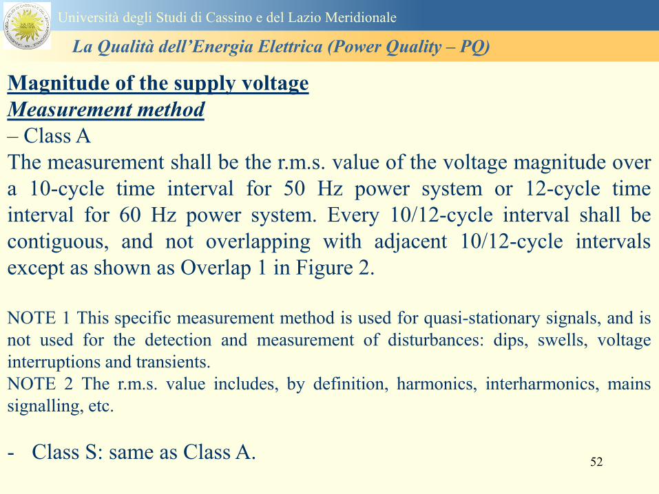
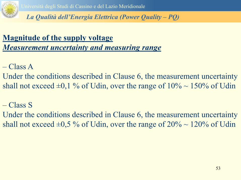
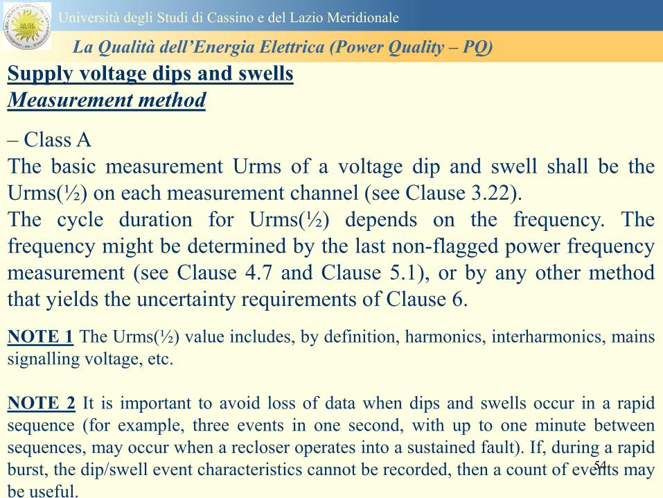
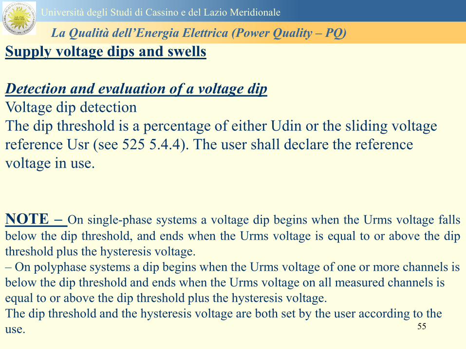
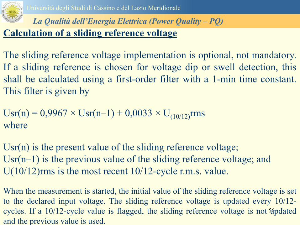
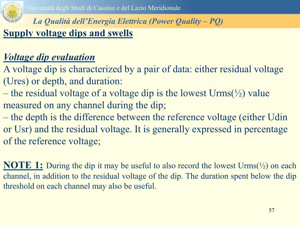
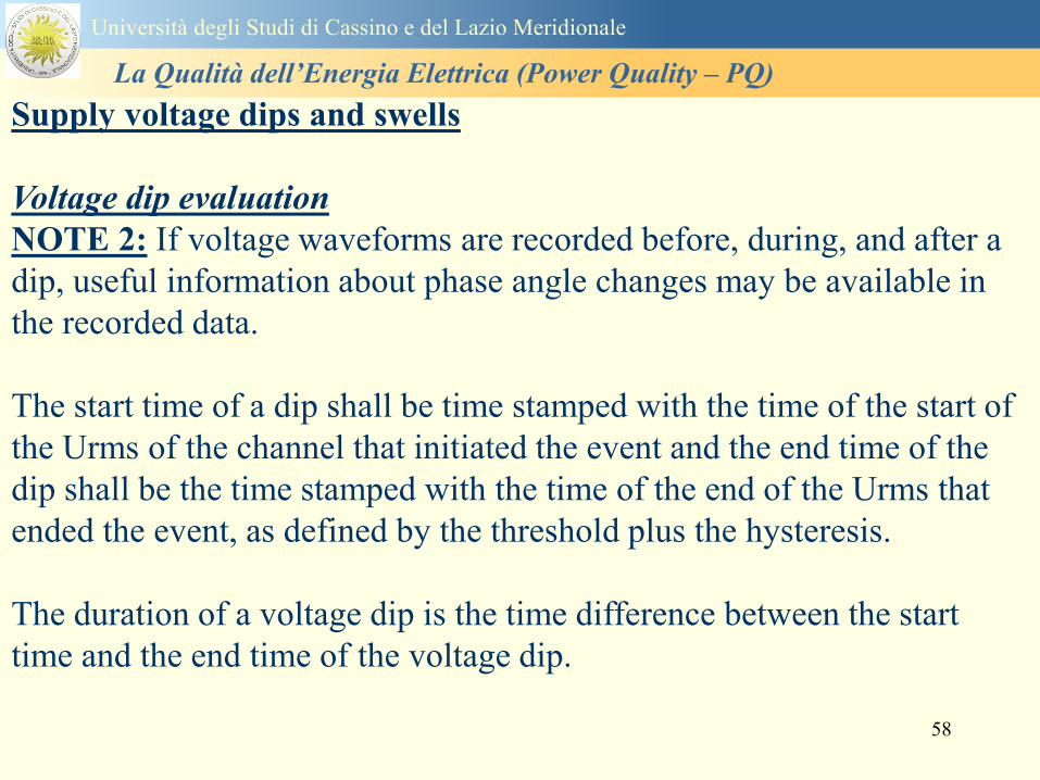
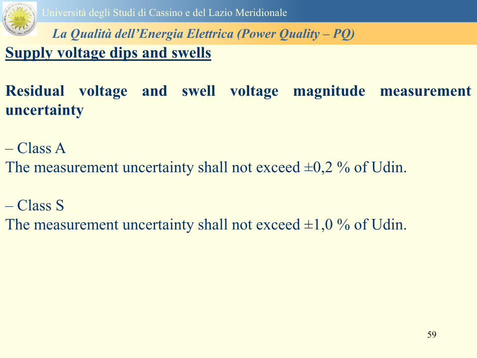
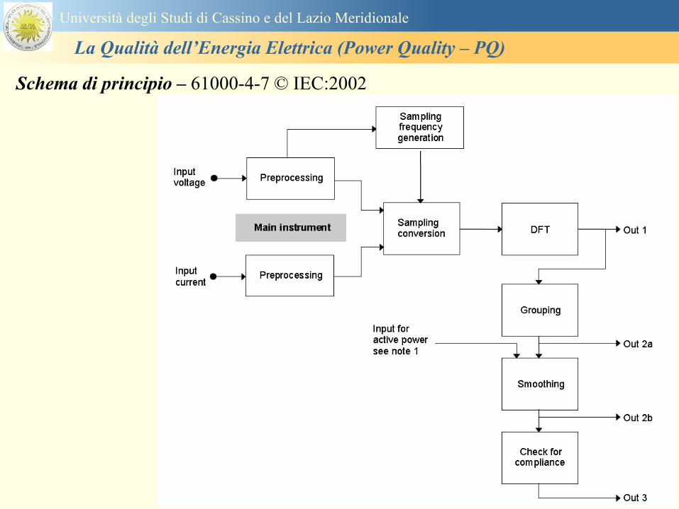
60
Schema di principio ndash 61000-4-7 copy IEC2002
Universitagrave degli Studi di Cassino e del Lazio Meridionale
La Qualitagrave dellrsquoEnergia Elettrica (Power Quality ndash PQ)
61
Universitagrave degli Studi di Cassino e del Lazio Meridionale
La Qualitagrave dellrsquoEnergia Elettrica (Power Quality ndash PQ)
62
Universitagrave degli Studi di Cassino e del Lazio Meridionale
La Qualitagrave dellrsquoEnergia Elettrica (Power Quality ndash PQ)
63
Inter-Armoniche Le inter-armoniche sono tensioni o correnti sinusoidali con frequenza diversa da un
multiplo intero della fondamentale la cui presenza determina una distorsione
(modulazione) della forma donda della tensione di alimentazione
CAUSE dai carichi che assorbono correnti inter-armoniche
- carichi commutati elettronicamente convertitori cascata subsincrona cicloconvertitori regolatori con
controllo a pacchetti di cicli ecc
- carichi con caratteristiche non lineari eo non stazionarie forni ad arco saldatrici ad arco ecc
Universitagrave degli Studi di Cassino e del Lazio Meridionale
La Qualitagrave dellrsquoEnergia Elettrica (Power Quality ndash PQ)
64
Universitagrave degli Studi di Cassino e del Lazio Meridionale
La Qualitagrave dellrsquoEnergia Elettrica (Power Quality ndash PQ)
Un porsquo di esempi e
consigli praticihellip
65
0V
50V
100V
150V
200V
250V
300V
350V
0ms 5ms 10ms 15ms 20ms
t
u
0A
1A
2A
3A
i
0V
50V
100V
150V
200V
250V
300V
350V
0ms 5ms 10ms 15ms 20ms
t
u
0A
1A
2A
3A
i
0V
50V
100V
150V
200V
250V
300V
350V
0ms 5ms 10ms 15ms 20ms
t
u
0A
1A
2A
3A
i
gleichgerichtete
Netzspannung
Kondensator-
spannung
gleichgerichteter
Netzstrom
The situation
today
bull Computed current and voltage profiles when a
230 V 58 W fluorescent lamp with an old-style
electronic ballast is driven on the phase wire of
a typical power distribution system
System voltage 230 V
System frequency 50 Hz
Source resistance 500 mW
Longitudinal induction 904 microH
System impedance 575 mW
Mean dc current 180 mA
Smoothing capacitance220 microF
66
And what about electronic ballasts that are rated over 25W
Introduce electronic power factor correction (PFC)
0V
20V
40V
60V
80V
100V
120V
140V
160V
180V
200V
220V
0deg 15deg 30deg 45deg
u
00A
03A
06A
09A
12A
i
67
Though todayrsquos ballasts are better if
rated gt25 W bull Only
the
small
ones
continu
e to
pollute
just like
PCs
TV sets
do
68
This leads to a number of
previously unknown effects bull 1 Deformed voltage curves
bull 2 Huge inrush current peaks
bull 3 Instrument dependent measured parameters
bull 4 Increased loading of phase conductors
bull 5 Loading and overloading of the neutral conductor
bull 6 Overheating and start-up problems of induction motors
bull 7 Additional stray losses in transformers
bull 8 Repercussions of generators upon the mains
bull 9 Influence of capacitors repercussions upon the mains
and four additional complications in TN-C systems
10 Stray currents in equipotential bonding system magnetic fields
11 Contamination of data streams by stray currents
12 Stray currents in the earthing system corrosion damage
13 Lightning currents in devices and equipment
69
1 Deformed voltage curves
bull in theory
-350V
-300V
-250V
-200V
-150V
-100V
-50V
0V
50V
100V
150V
200V
250V
300V
350V
0 5 10 15 20
t ms
u
System voltage profile when driving
a single-phase load comprising
twenty 58 W energy-saver lamps in
parallel on a typical 230 V power
system
70
and in practice
bull An actual
current profile
bull
bull and
bull a voltage profile
bull
bull recorded in a large storage
dispatch and administrative
building
71
at home or in industrial environments
bull
bull Television 40
W
bull 200 Vdiv 2
Adiv
bull 5 msdiv
Harmonic
spectrum
Frequency
converter
50 Adiv
Phase currents
I1=I2=I3=160 A
IN=295 A
5 msdiv
72
Every periodic waveform can be written
as the infinite sum of sinusoidal waves
-175
-150
-125
-100
-75
-50
-25
0
25
50
75
100
125
150
175
0 5 10 15 20
t ms
i
mA
itot
i1
Synthesis of a triangular current profile 100mA
Content fundamental I = 99 mA Isup2 = 9855 mAsup2
Sum of squares Isup2 = 9855 mAsup2
Root of sum = RMS value I = 99 mA
-175
-150
-125
-100
-75
-50
-25
0
25
50
75
100
125
150
175
0 5 10 15 20
t ms
i
mA
itot
i1
i3
Synthesis of a triangular current profile 100mA
Content fundamental I = 99 mA Isup2 = 9855 mAsup2
Cont 3 rd harmonic I = -11 mA Isup2 = 122 mAsup2
Sum of squares Isup2 = 9977 mAsup2
Root of sum = RMS value I = 100 mA
-175
-150
-125
-100
-75
-50
-25
0
25
50
75
100
125
150
175
0 5 10 15 20
t ms
i
mA
itot
i1
i3
i5
Synthesis of a triangular current profile 100mA
Content fundamental I = 99 mA Isup2 = 9855 mAsup2
Cont 3 rd harmonic I = -11 mA Isup2 = 122 mAsup2
Cont 5 th harmonic I = 4 mA Isup2 = 16 mAsup2
Sum of squares Isup2 = 9993 mAsup2
Root of sum = RMS value I = 100 mA
-175
-150
-125
-100
-75
-50
-25
0
25
50
75
100
125
150
175
0 5 10 15 20
t ms
i
mA
itot
i1
i3
i5
i7
Synthesis of a triangular current profile 100mA
Content fundamental I = 99 mA Isup2 = 9855 mAsup2
Cont 3 rd harmonic I = -11 mA Isup2 = 122 mAsup2
Cont 5 th harmonic I = 4 mA Isup2 = 16 mAsup2
Cont 7 th harmonic I = -2 mA Isup2 = 4 mAsup2
Sum of squares Isup2 = 9997 mAsup2
Root of sum = RMS value I = 100 mA
-175
-150
-125
-100
-75
-50
-25
0
25
50
75
100
125
150
175
0 5 10 15 20
t ms
i
mA
itot i1
i3 i5
i7 i9
Synthesis of a triangular current profile 100mA
Content fundamental I = 99 mA Isup2 = 9855 mAsup2
Cont 3 rd harmonic I = -11 mA Isup2 = 122 mAsup2
Cont 5 th harmonic I = 4 mA Isup2 = 16 mAsup2
Cont 7 th harmonic I = -2 mA Isup2 = 4 mAsup2
Cont 9 th harmonic I = 1 mA Isup2 = 2 mAsup2
Sum of squares Isup2 = 9998 mAsup2
Root of sum = RMS value I = 100 mA
-175
-150
-125
-100
-75
-50
-25
0
25
50
75
100
125
150
175
0 5 10 15 20
t ms
i
mA
itot i1
i3 i5
i7 i9
i11
Synthesis of a triangular current profile 100mA
Content fundamental I = 99 mA Isup2 = 9855 mAsup2
Cont 3 rd harmonic I = -11 mA Isup2 = 122 mAsup2
Cont 5 th harmonic I = 4 mA Isup2 = 16 mAsup2
Cont 7 th harmonic I = -2 mA Isup2 = 4 mAsup2
Cont 9 th harmonic I = 1 mA Isup2 = 2 mAsup2
Cont 11 th harmonic I = -1 mA Isup2 = 1 mAsup2
Sum of squares Isup2 = 9999 mAsup2
Root of sum = RMS value I = 100 mA
-175
-150
-125
-100
-75
-50
-25
0
25
50
75
100
125
150
175
0 5 10 15 20
t ms
i
mA
itot i1
i3 i5
i7 i9
i11 i13
Synthesis of a triangular current profile 100mA
Content fundamental I = 99 mA Isup2 = 9855 mAsup2
Cont 3 rd harmonic I = -11 mA Isup2 = 122 mAsup2
Cont 5 th harmonic I = 4 mA Isup2 = 16 mAsup2
Cont 7 th harmonic I = -2 mA Isup2 = 4 mAsup2
Cont 9 th harmonic I = 1 mA Isup2 = 2 mAsup2
Cont 11 th harmonic I = -1 mA Isup2 = 1 mAsup2
Cont 13 th harmonic I = 1 mA Isup2 = 0 mAsup2
Sum of squares Isup2 = 9999 mAsup2
Root of sum = RMS value I = 100 mA
-175
-150
-125
-100
-75
-50
-25
0
25
50
75
100
125
150
175
0 5 10 15 20
t ms
i
mA
itot i1
i3 i5
i7 i9
i11 i13
i15
Synthesis of a triangular current profile 100mA
Content fundamental I = 99 mA Isup2 = 9855 mAsup2
Cont 3 rd harmonic I = -11 mA Isup2 = 122 mAsup2
Cont 5 th harmonic I = 4 mA Isup2 = 16 mAsup2
Cont 7 th harmonic I = -2 mA Isup2 = 4 mAsup2
Cont 9 th harmonic I = 1 mA Isup2 = 2 mAsup2
Cont 11 th harmonic I = -1 mA Isup2 = 1 mAsup2
Cont 13 th harmonic I = 1 mA Isup2 = 0 mAsup2
Cont 15 th harmonic I = 0 mA Isup2 = 0 mAsup2
Sum of squares Isup2 = 10000 mAsup2
Root of sum = RMS value I = 100 mA
-175
-150
-125
-100
-75
-50
-25
0
25
50
75
100
125
150
175
0 5 10 15 20
t ms
i
mA
itot i1
i3 i5
i7 i9
i11 i13
i15 i17
Synthesis of a triangular current profile 100mA
Content fundamental I = 99 mA Isup2 = 9855 mAsup2
Cont 3 rd harmonic I = -11 mA Isup2 = 122 mAsup2
Cont 5 th harmonic I = 4 mA Isup2 = 16 mAsup2
Cont 7 th harmonic I = -2 mA Isup2 = 4 mAsup2
Cont 9 th harmonic I = 1 mA Isup2 = 2 mAsup2
Cont 11 th harmonic I = -1 mA Isup2 = 1 mAsup2
Cont 13 th harmonic I = 1 mA Isup2 = 0 mAsup2
Cont 15 th harmonic I = 0 mA Isup2 = 0 mAsup2
Cont 17 th harmonic I = 0 mA Isup2 = 0 mAsup2
Sum of squares Isup2 = 10000 mAsup2
Root of sum = RMS value I = 100 mA
73
whose frequencies called harmonics are
integer multiples of the fundamental frequency
-175
-150
-125
-100
-75
-50
-25
0
25
50
75
100
125
150
175
0 5 10 15 20
t ms
i
mA
itot
i1
Synthesis of a rectangular current profile 100mA
Content fundamental I = 90 mA Isup2 = 8106 mAsup2
Sum of squares Isup2 = 8106 mAsup2
Root of sum = RMS value I = 90 mA
-175
-150
-125
-100
-75
-50
-25
0
25
50
75
100
125
150
175
0 5 10 15 20
t ms
i
mA
itot
i1
i3
Synthesis of a rectangular current profile 100mA
Content fundamental I = 90 mA Isup2 = 8106 mAsup2
Cont 3 rd harmonic I = 30 mA Isup2 = 901 mAsup2
Sum of squares Isup2 = 9006 mAsup2
Root of sum = RMS value I = 95 mA
-175
-150
-125
-100
-75
-50
-25
0
25
50
75
100
125
150
175
0 5 10 15 20
t ms
i
mA
itot
i1
i3
i5
Synthesis of a rectangular current profile 100mA
Content fundamental I = 90 mA Isup2 = 8106 mAsup2
Cont 3 rd harmonic I = 30 mA Isup2 = 901 mAsup2
Cont 5 th harmonic I = 18 mA Isup2 = 324 mAsup2
Sum of squares Isup2 = 9331 mAsup2
Root of sum = RMS value I = 97 mA
-175
-150
-125
-100
-75
-50
-25
0
25
50
75
100
125
150
175
0 5 10 15 20
t ms
i
mA
itot
i1
i3
i5
i7
Synthesis of a rectangular current profile 100mA
Content fundamental I = 90 mA Isup2 = 8106 mAsup2
Cont 3 rd harmonic I = 30 mA Isup2 = 901 mAsup2
Cont 5 th harmonic I = 18 mA Isup2 = 324 mAsup2
Cont 7 th harmonic I = 13 mA Isup2 = 165 mAsup2
Sum of squares Isup2 = 9496 mAsup2
Root of sum = RMS value I = 97 mA
-175
-150
-125
-100
-75
-50
-25
0
25
50
75
100
125
150
175
0 5 10 15 20
t ms
i
mA
itot i1
i3 i5
i7 i9
Synthesis of a rectangular current profile 100mA
Content fundamental I = 90 mA Isup2 = 8106 mAsup2
Cont 3 rd harmonic I = 30 mA Isup2 = 901 mAsup2
Cont 5 th harmonic I = 18 mA Isup2 = 324 mAsup2
Cont 7 th harmonic I = 13 mA Isup2 = 165 mAsup2
Cont 9 th harmonic I = 10 mA Isup2 = 100 mAsup2
Sum of squares Isup2 = 9596 mAsup2
Root of sum = RMS value I = 98 mA
-175
-150
-125
-100
-75
-50
-25
0
25
50
75
100
125
150
175
0 5 10 15 20
t ms
i
mA
itot i1
i3 i5
i7 i9
i11
Synthesis of a rectangular current profile 100mA
Content fundamental I = 90 mA Isup2 = 8106 mAsup2
Cont 3 rd harmonic I = 30 mA Isup2 = 901 mAsup2
Cont 5 th harmonic I = 18 mA Isup2 = 324 mAsup2
Cont 7 th harmonic I = 13 mA Isup2 = 165 mAsup2
Cont 9 th harmonic I = 10 mA Isup2 = 100 mAsup2
Cont 11 th harmonic I = 8 mA Isup2 = 67 mAsup2
Sum of squares Isup2 = 9663 mAsup2
Root of sum = RMS value I = 98 mA
-175
-150
-125
-100
-75
-50
-25
0
25
50
75
100
125
150
175
0 5 10 15 20
t ms
i
mA
itot i1
i3 i5
i7 i9
i11 i13
Synthesis of a rectangular current profile 100mA
Content fundamental I = 90 mA Isup2 = 8106 mAsup2
Cont 3 rd harmonic I = 30 mA Isup2 = 901 mAsup2
Cont 5 th harmonic I = 18 mA Isup2 = 324 mAsup2
Cont 7 th harmonic I = 13 mA Isup2 = 165 mAsup2
Cont 9 th harmonic I = 10 mA Isup2 = 100 mAsup2
Cont 11 th harmonic I = 8 mA Isup2 = 67 mAsup2
Cont 13 th harmonic I = 7 mA Isup2 = 48 mAsup2
Sum of squares Isup2 = 9711 mAsup2
Root of sum = RMS value I = 99 mA
-175
-150
-125
-100
-75
-50
-25
0
25
50
75
100
125
150
175
0 5 10 15 20
t ms
i
mA
itot i1
i3 i5
i7 i9
i11 i13
i15
Synthesis of a rectangular current profile 100mA
Content fundamental I = 90 mA Isup2 = 8106 mAsup2
Cont 3 rd harmonic I = 30 mA Isup2 = 901 mAsup2
Cont 5 th harmonic I = 18 mA Isup2 = 324 mAsup2
Cont 7 th harmonic I = 13 mA Isup2 = 165 mAsup2
Cont 9 th harmonic I = 10 mA Isup2 = 100 mAsup2
Cont 11 th harmonic I = 8 mA Isup2 = 67 mAsup2
Cont 13 th harmonic I = 7 mA Isup2 = 48 mAsup2
Cont 15 th harmonic I = 6 mA Isup2 = 36 mAsup2
Sum of squares Isup2 = 9747 mAsup2
Root of sum = RMS value I = 99 mA
-175
-150
-125
-100
-75
-50
-25
0
25
50
75
100
125
150
175
0 5 10 15 20
t ms
i
mA
itot i1
i3 i5
i7 i9
i11 i13
i15 i17
Synthesis of a rectangular current profile 100mA
Content fundamental I = 90 mA Isup2 = 8106 mAsup2
Cont 3 rd harmonic I = 30 mA Isup2 = 901 mAsup2
Cont 5 th harmonic I = 18 mA Isup2 = 324 mAsup2
Cont 7 th harmonic I = 13 mA Isup2 = 165 mAsup2
Cont 9 th harmonic I = 10 mA Isup2 = 100 mAsup2
Cont 11 th harmonic I = 8 mA Isup2 = 67 mAsup2
Cont 13 th harmonic I = 7 mA Isup2 = 48 mAsup2
Cont 15 th harmonic I = 6 mA Isup2 = 36 mAsup2
Cont 17 th harmonic I = 5 mA Isup2 = 28 mAsup2
Sum of squares Isup2 = 9775 mAsup2
Root of sum = RMS value I = 99 mA
74
Even far better simulations are
available free of charge at
bull wwwpowerstandardscomMcEachern
75
-4A
-3A
-2A
-1A
0A
1A
2A
3A
4A
0ms 5ms 10ms 15ms 20ms
t
i
-4A
-3A
-2A
-1A
0A
1A
2A
3A
4A
0ms 5ms 10ms 15ms 20ms
t
i
Applying the Fourier
analysis to a real PC
current does not work
directly
bull
bull but it can be
modelled by a similar
triangular curve in
which not all of the
higher harmonics
have been included
Triangular current profile of
the same amplitude and a
pulse duty cycle of 17
Input current of a PC
with monitor
76
Analysis of the model triangular waveform
-400
-350
-300
-250
-200
-150
-100
-50
0
50
100
150
200
250
300
350
400
0 5 10 15 20
t ms
iI
itot(t) L1 [A] i1(t) L1 [A]
i3(t) L1 [A] i5(t) L1 [A]
i7(t) L1 [A] i9(t) L1 [A]
i11(t) L1 [A] i13(t) L1 [A]
i15(t) L1 [A] i17(t) L1 [A]
77
M3
Harmonics
Energy
(active
power)
L1
L2
L3
N
PE
Important
bull Harmonics are created within the loads
themselves and can flow ldquoupstreamrdquo to
contaminate the power system
78
-6A
-5A
-4A
-3A
-2A
-1A
0A
1A
2A
3A
4A
5A
6A
0ms 5ms 10ms 15ms 20ms
t
i
Squared values
Without
Fundamental 502 mA 251986 mAsup2 the fundamental
3rd harmonic -479 mA 229000 mAsup2 229000 mAsup2
5th harmonic 434 mA 188595 mAsup2 188595 mAsup2
7th harmonic -374 mA 139903 mAsup2 139903 mAsup2
9th harmonic 304 mA 92527 mAsup2 92527 mAsup2
11th harmonic -232 mA 53671 mAsup2 53671 mAsup2
13th harmonic 163 mA 26600 mAsup2 26600 mAsup2
15th harmonic -104 mA 10780 mAsup2 10780 mAsup2
17th harmonic 57 mA 3299 mAsup2 3299 mAsup2
Sum of the squares 996362 mAsup2 744377 mAsup2
Root thereof 998 mAeff THD = 863 mA
What actually is THD Example shown here triangular current
profile with an rms current of 1000 mA
and a pulse duty cycle of 17
THDr (root mean square) = 863mA1000mA = 86
THDf (fundamental) = 863mA502mA = 172
79
Effect on phase-to-neutral
and phase-to-phase voltages
bull Recorded
on June
30 2002
230 p
m
bull What
was the
matter
then
bull The
soccer
final
Germany
vs
Brazil
80
The triple-N harmonics drive
a circulating current in the
delta winding of a distribution
transformer
bull but the
bull voltage harmonics
propagate into the next
low-voltage power
distribution system
81 0V
50V
100V
150V
200V
250V
300V
350V
400V
450V
500V
550V
0 10 20 30 40 50
t ms
u
0A
10A
20A
30A
40A
50A
60A
70A
80A
90A
100A
110A
120A
130A
140A
150A
i
Switching on just as supply voltage passes through zero
0V
50V
100V
150V
200V
250V
300V
350V
400V
450V
500V
550V
0 10 20 30 40 50
t ms
u
0A
10A
20A
30A
40A
50A
60A
70A
80A
90A
100A
110A
120A
130A
140A
150A
i
Switching on just as supply voltage is at its peak
2 Huge inrush current peaks
ndash in theory
82
and in practice
bull Inrush current of a
compact energy-
saver lamp and its
effect on the system
voltage (recorded at
the Technical
University of
Budapest)
bull
83
enables us to infer what
happens when run by a
normal three-phase supply
The same fluorescent lamp
with a magnetic ballast
bull The behaviour measured
when connected to
a dc supply
bull
Behaviour of a 58 W fluorescent lamp connected to a dc
supply
0
20
40
60
80
100
120
140
160
180
200
0 200 400 600 800 1000 1200
i mA
u
V
Measurement
Behaviour of a 58 W fluorescent lamp connected to a dc
supply
0
20
40
60
80
100
120
140
160
180
200
0 200 400 600 800 1000 1200
i mA
u
V
MeasurementCalculation
-350
-300
-250
-200
-150
-100
-50
0
50
100
150
200
250
300
350
0 5 10 15 20
t ms
u
V
-10
-08
-06
-04
-02
00
02
04
06
08
10
i
A
Systems voltage
Current
-350
-300
-250
-200
-150
-100
-50
0
50
100
150
200
250
300
350
0 5 10 15 20
t ms
u
V
-10
-08
-06
-04
-02
00
02
04
06
08
10
i
A
Systems voltage
Lamp voltage
Current
84
Warning ldquoCompensationrdquo is not
always what you think it is
bull Distinguish
between
bull Reactive
power
compensatio
n
aka power
factor
correction
Remedial
measure
Parallel (or
sometimes series)
compensation
using capacitors
Filter circuits
tuned to the
individual harmonic
frequencies
Harmonic
compensation
85
5 (Over)loading the neutral conductor
bull Magnetic ballast Old-style electronic ballast
-25A
-20A
-15A
-10A
-05A
00A
05A
10A
15A
20A
25A
0 5 10 15 20
t ms i
i(t) N
-25A
-20A
-15A
-10A
-05A
00A
05A
10A
15A
20A
25A
0 5 10 15 20
t ms
i
i(t) N
-25A
-20A
-15A
-10A
-05A
00A
05A
10A
15A
20A
25A
0 5 10 15 20
t ms
i
i(t) L1 i(t) L2 i(t) L3
-25A
-20A
-15A
-10A
-05A
00A
05A
10A
15A
20A
25A
0 5 10 15 20
t ms
i
i(t) L1
i(t) L2
i(t) L3
86
Adding the 3rd
harmonics
in the
neutral
wire
-150-100-50
050
100150
0deg 30deg 60deg 90deg 120deg 150deg 180deg 210deg 240deg 270deg 300deg 330deg 360deg
L1
-150-100-50
050
100150
0deg 30deg 60deg 90deg 120deg 150deg 180deg 210deg 240deg 270deg 300deg 330deg 360deg
L2
-150-100-50
050
100150
0deg 30deg 60deg 90deg 120deg 150deg 180deg 210deg 240deg 270deg 300deg 330deg 360deg
L3
-450-400-350-300-250-200-150-100-50
050
100150200250300350400450
0deg 30deg 60deg 90deg 120deg 150deg 180deg 210deg 240deg 270deg 300deg 330deg 360deg
f
iicirc
N
Physics dictates
that at any
moment in time
the phase and
neutral currents
must sum to zero
87
Effect on a three-phase ac motor
appears almost identical
bull The same motor is being
driven
simultaneously in
these three modes
homopolar system
zero-sequence system
direct system
positive-sequence system
inverse system
negative-sequence system
88
The transformer
influences the load
89
but the load also effects
the transformer
Total transformer loss is
2
)()(
nom
nomCunomFeLossI
IPPP
While total transformer loss really is
2
)(
2
)(
2
)(
nomnom
nomad
nom
nomCu
nom
nomFeLossI
I
f
fP
I
IP
U
UPP
90
6 ldquosupplementaryrdquo additional losses
in transformers
can be calculated rapidly
using the following two
simple formulae 50
2
2
1
2
11
Nn
n
nqh
I
In
I
I
e
eK
50
1
2
1
1
50
1
2
Nn
n
nNn
n
nI
IIII
where
Oh well
perhaps a practical
example is clearer
1000 compact 11W
(15VA) energy-saver
lamps powered by a
15kVA transformer
uSC=4 Pa=01PCu
Harmonics of an Osram Dulux 11W
CFL and a serial impedance of
R =291Ω amp X L=113Ω
U U sup2 I L I Lsup2 P aP Cu
n V Vsup2 mA mAsup2
1 2302 529920 485 23523 56
3 83 689 371 13764 295
5 107 1145 203 4121 245
7 43 185 53 281 33
9 11 12 30 90 17
11 23 53 38 144 42
13 10 10 15 23 09
15 06 04 15 23 12
17 11 12 15 23 15
19 05 03 09 08 07
21 05 03 13 17 18
23 06 04 08 06 08
25 04 02 06 04 05
27 06 04 08 06 11
29 04 02 05 03 05
31 03 01 05 03 06
33 03 01 05 03 06
35 03 01 04 02 05
37 03 01 04 02 05
39 03 01 03 01 03
41 01 00 03 01 04
43 02 00 02 00 02
45 01 00 02 00 02
47 01 00 02 00 02
49 01 00 01 00 01
51 01 00 01 00 01
P aP Cu = 814814
etc
etc
91
Harmonics measurement on an
Osram Dulux 11W compact
fluorescent lamp
U U sup2 I L I Lsup2 P addP Cu
n V Vsup2 mA mAsup2
1 2327 541493 489 23912 37
3 06 04 391 15288 215
5 44 194 264 6970 273
7 23 53 200 4000 307
9 01 00 192 3686 467
11 01 00 166 2756 522
13 01 00 127 1613 427
15 01 00 110 1210 426
17 01 00 102 1040 471
19 01 00 87 757 428
21 01 00 77 593 409
23 01 00 73 533 441
25 01 00 61 372 364
27 01 00 49 240 274
29 01 00 42 176 232
31 01 00 36 130 195
33 01 00 30 90 153
35 01 00 33 109 209
37 01 00 31 96 206
39 01 00 25 63 149
41 01 00 25 63 164
43 01 00 25 63 181
45 01 00 19 36 114
47 01 00 18 32 112
49 01 00 19 36 136
51 01 00 16 26 104
P aP Cu = 7017
To some extent
the transformer
protects itself
bull Always remember to
consider it
bull If the influence of the
transformer upon the load
did not exist then the
influence of the load upon
the transformer would be
nearly 9 times as high
7017
etc
etc
92
Rule of thumb Select transformers 35
larger than specification by apparent
power would require
bull This suffices to err
on the safe side
even in the worst
case and can
hardly ever be
wrong since
maximum
efficiency always
lies between 25
and 50 of rated
load
Efficiency of a 1 MVA transformer plotted against loading
985
986
987
988
989
990
991
992
993
994
0 25 50 75 100 125
Relative load h
Design with max Cu loss and min Fe loss
Design with min Cu loss and max Fe loss
1 MVA oil transformer according to HD 428
93
Measured response of an 11 W
fluorescent lamp operated with a
magnetic ballast
94
We are
dealing with
a complex
problem
bull These
effects
are not
isolated
but are
mutuall
y inter-
depende
nt
Effects 2 3 and 5 can be demonstrated
on DKIrsquos display panel
95
A conventional approximately resistive-
inductive load
mA
N L1 L2 L3
Two conventional approximately
resistive-inductive loads Three conventional approximately
resistive-inductive loads
96
A modern electronic load
mA
N
Two modern electronic loads Three modern electronic loads
L1 L2 L3
97
Discoveries on a
refurbished
junction box
System voltage
(as trigger
signal)
Current in the
earthing
conductor
between the
consumer unit
and the
bonding
busbar
98
The TN-C system that was perfectly
adequate some years ago is unable to meet
present-day requirements
-6
-4
-2
0
2
4
6
0 5 10 15 20
t ms
i
A
-350
-300
-250
-200
-150
-100
-50
0
50
100
150
200
250
300
350
0 5 10 15 20
t ms
u
V
99
ldquoTHFrdquo
(third harmonic
filter) made in
Finland
In certain situations this affordable
filter can be of help
German
version ldquoTHXrdquo
100
0Ω
5 Ω
1 0 Ω
1 5 Ω
2 0 Ω
2 5 Ω
3 0 Ω
3 5 Ω
4 0 Ω
0Hz 50Hz 100Hz 150Hz 200Hz 250Hz 300Hz
f
Z
-90deg
-75deg
-60deg
-45deg
-30deg
-15deg
0deg
15deg
30deg
45deg
60deg
75deg
90deg
φ
Reactorreactance
Capacitorreactance
Parallelimpedace
Phase angle
Data and frequency response
of the filter
bull 1320 microF
bull 875
14 mW microH
101
The filter in use
bull In a nursery running sodium vapour lamps (500 kW)
In a typical office and administrative building
102
The EMC Transformer from Switzerland
7 The effects of stray magnetic fields
in TN-C systems
bull ldquoWhen we build transformers the first thing we focus on is complying with our customersrsquo
requirements and only then on complying with standards Why Because it is customer
needs and not standards that offer real scope for product innovationrdquo
103
8 In a TN-C system problems arise from data
streams and working currents mixing
bull Others who
have drawn
attention to
this source of
data
transmission
errors include
engineering
and insurance
companies experts
consultants and many
others besides
104
9 Increased corrosive damage
bull This (once) galvanized steel strip ndash the earth
electrode of a TN-C-S system ndash was located close
to the transformer station
Side facing
transformer
station
Side facing
transformer
station
Side facing away
from transformer
station
Side facing away
from transformer
station
105
bull WRONG RIGHT
Working currents have no place
in earthing systems and
protective conductors
106
10 Lightning currents
107
Which bridge to
cross which bridge to
burn
Sometimes you just donlsquot
believe what you see
This one will soon
look rather charred
IEC 60364-5-54
54343 If from any point of the installation the neutral and protective
functions are provided by separate conductors it is not permitted to
connect the neutral conductor to any other earthed part of the
installation
108
Well then the rest is no longer a
miracle
109
110
111
Another means of (over)loading the
neutral conductor
bull dc currents
Original ldquoFakerdquo
112
and their
effects U = 2285 V
I = 92 mA
P = 182 W
S = 209 VA
Q = 103 VAr
LF = 087
cos φ = 099
U = 2243 V
I = 126 A
P = 380 W
S = 2860 VA
Q = 2830 VAr
No-load current in a
toroidal-core
transformer
200 VA
-350-300
-250-200
-150-100
-500
50
100150
200250
300350
0 10 20 30 40
t ms
u
V
-12
-10
-8
-6
-4
-2
0
2
4
6
8
10
12
i
mA
Voltage
Current
No-load current in a toroidal-core
transformer 200 VA when
running a 1500 W
hairdryer at
half-power
in parallel
-350-300
-250-200
-150-100
-500
50
100150
200250
300350
0 5 10 15 20 25 30 35 40
t ms
u
V
-6
-5
-4
-3
-2
-1
0
1
2
3
4
5
6
i
A
Voltage
Current
113
The later models donlsquot do it any more
The EN 61000-3-2 has at least managed
to put an end to this approach
Domestic appliances Max 105 A of 2nd harmonic
114
An electrical engineering wonder
dc current generates ac voltage
115
Spicing things up with a pinch of HF
electronic halogen lamp transformers
116
Decorative HF reactors
117
Current and power loss as a function of voltage
00
02
04
06
08
10
12
14
16
18
0 40 80 120 160 200 240
U V
I
A
0
20
40
60
80
100
120
PV
W
I [A]
Pv [W]
Power loss capacitor voltage
and total voltage as a function of current
0
50
100
150
200
250
300
350
400
450
000 025 050 075 100 125 150
I A
U
V
0
5
10
15
20
25
30
35
40
45
50
PV
W
Utot [V] Eff
UR [V] Eff
Pv [W]
The passive
harmonic filter
made of readily
available
components
bull is both
reliable
118
and effective
bull befor
e
bull after
119
Half the solution has already been implemented
120
And if thatrsquos not enough
bull Passive filter circuits will do it
121
So what do we need to do
bull In low-voltage power distribution systems
Do not use cables in which the neutral or protective earth conductor has a
reduced cross-section
Use only 5-core cable Do not install TN-C- or TN-C-S systems
Be generous when dimensioning conductor cross-sections This helps to
reduce line voltage drops and thus reduces the effect of current distortions on
the voltage as well as lowering energy losses (see VDE 0298 Part 100)
Generously dimensioned conductors will have no problem coping with any
future increase in demand
Only use measuring instruments that display the true root mean square value
(TRMS meters)
In medium-voltage power distribution systems
Use a varied mix of distribution transformers with different vector groups
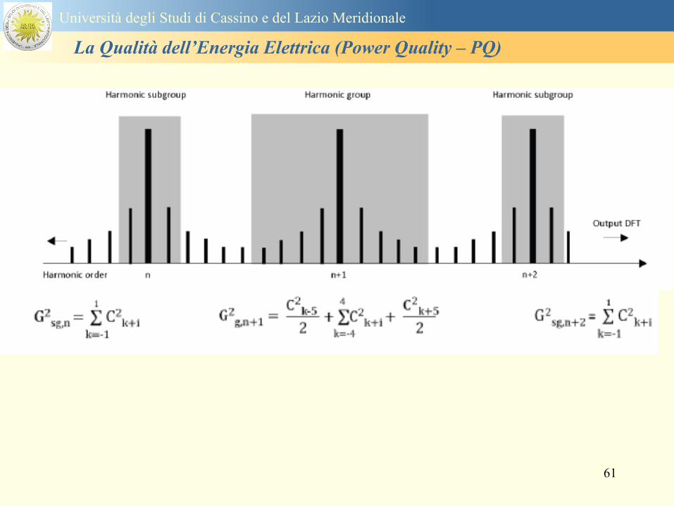
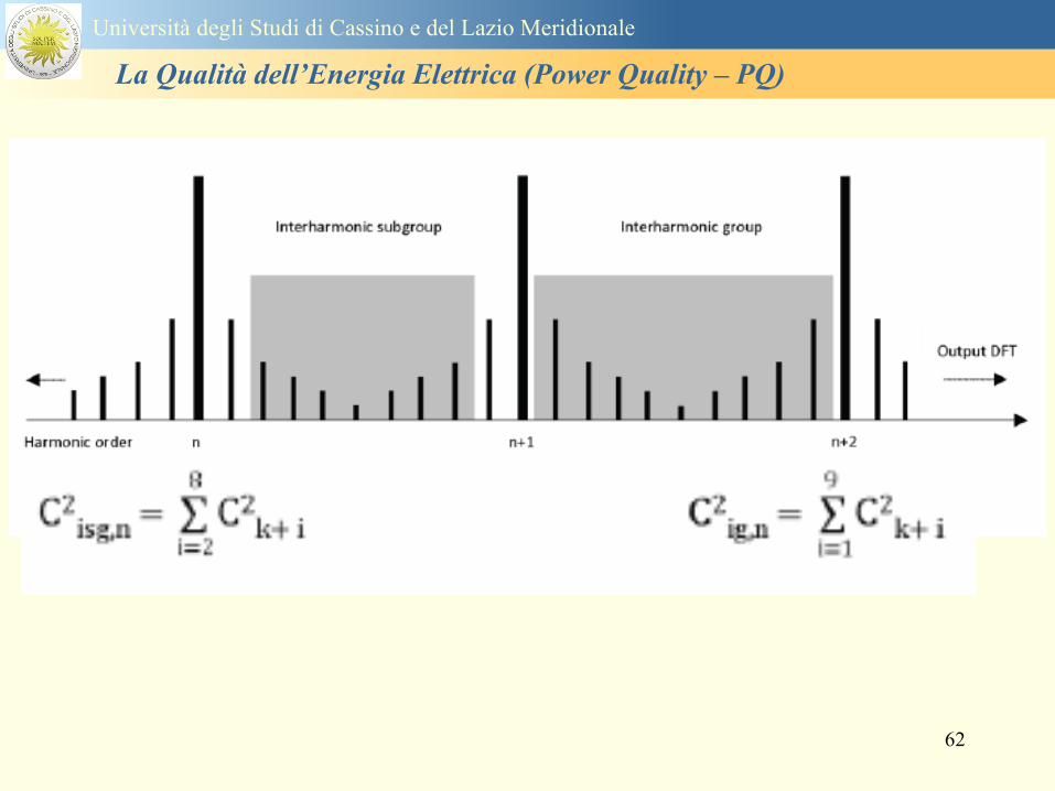
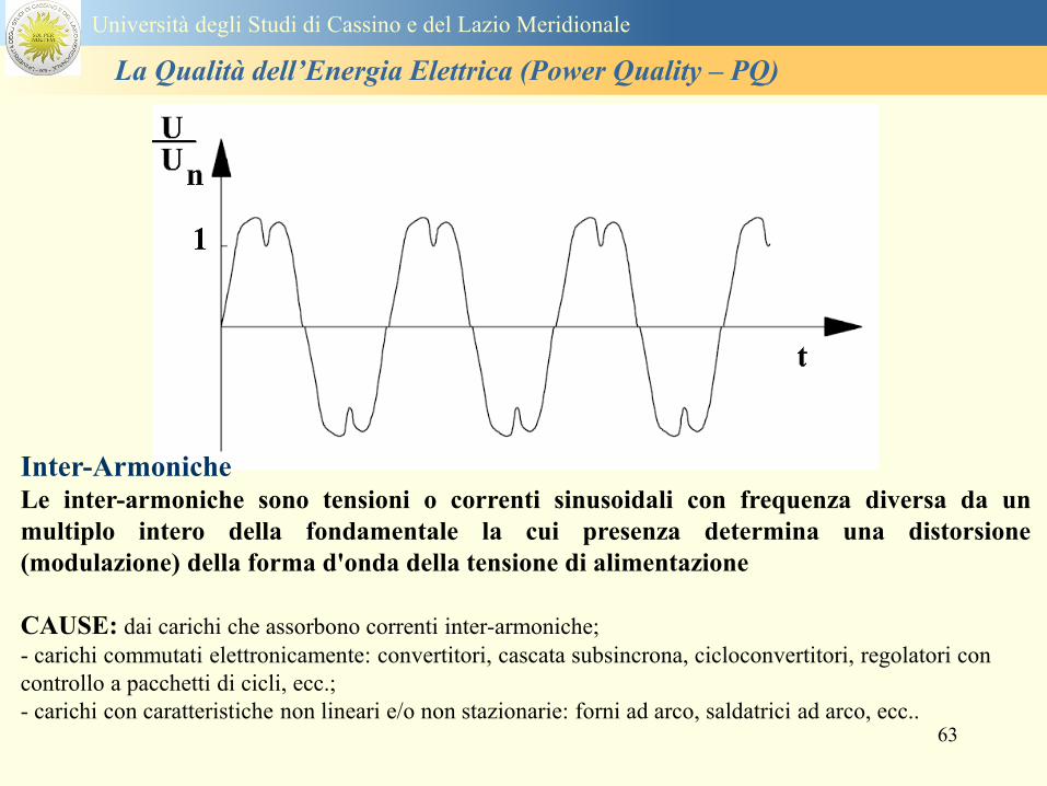
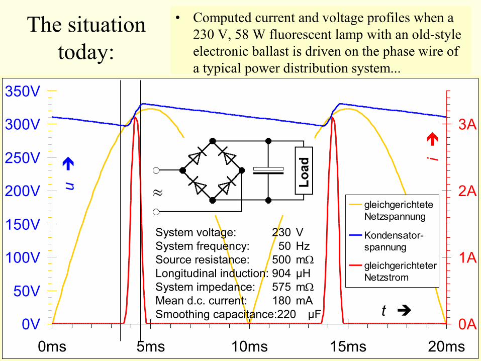
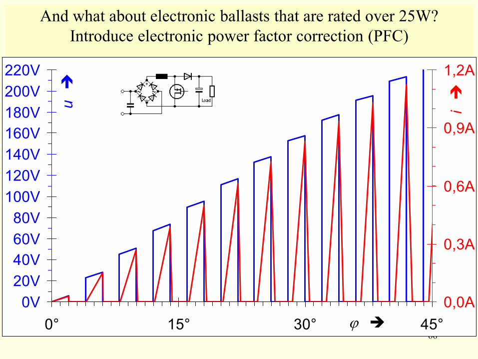
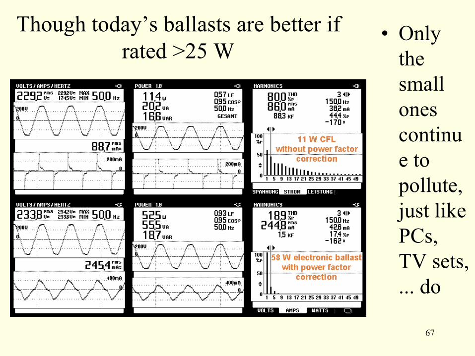
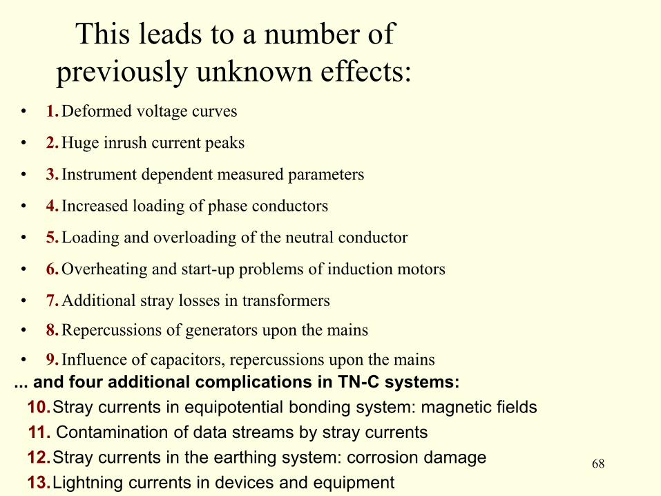
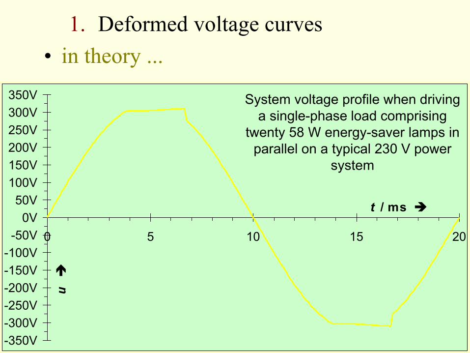
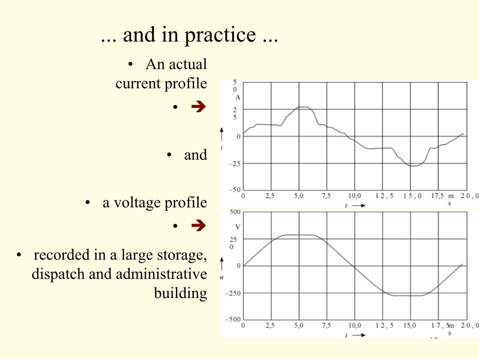
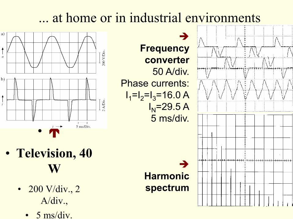
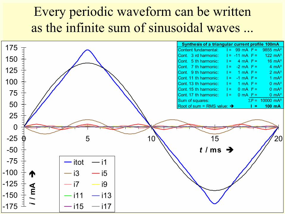
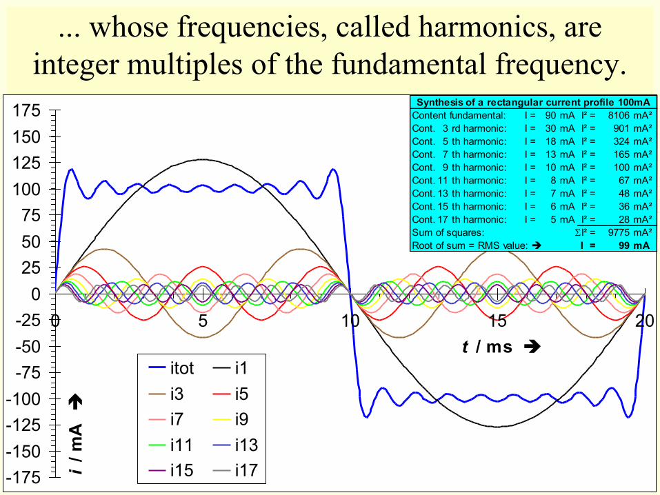
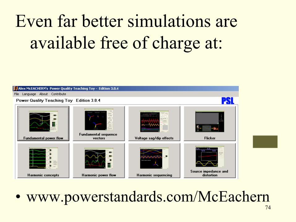
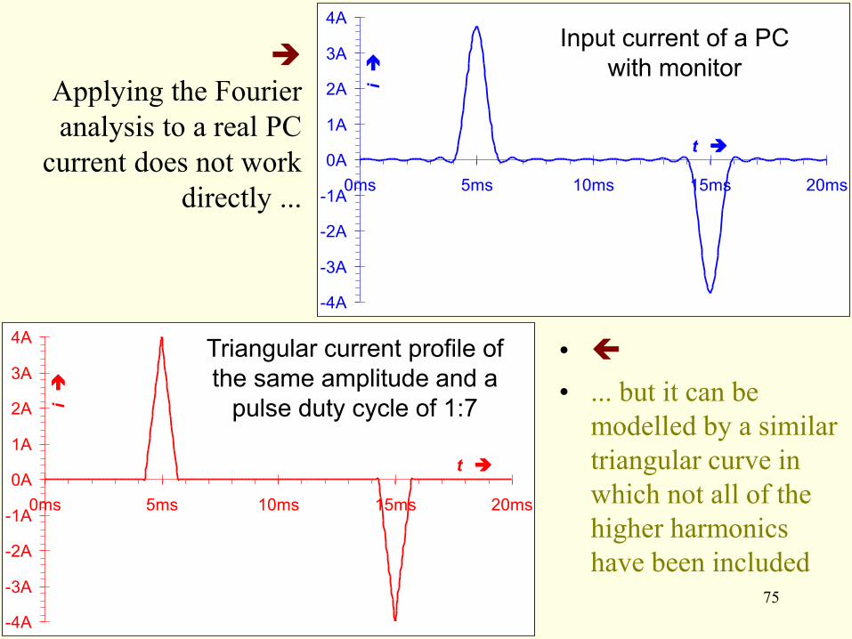
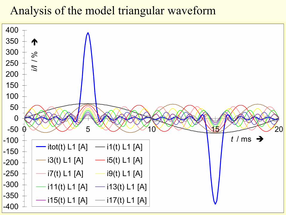
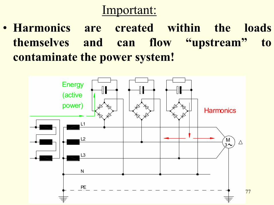
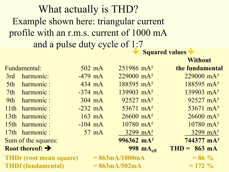
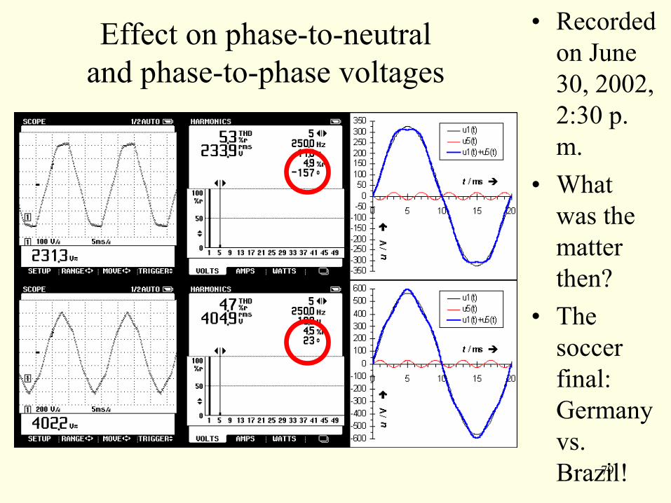
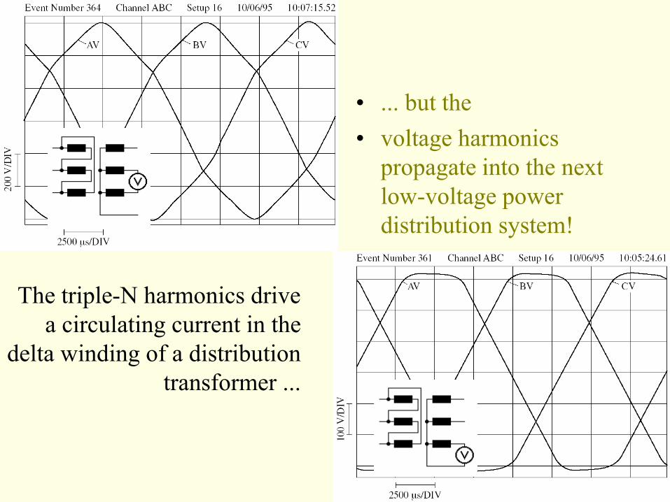
80
The triple-N harmonics drive
a circulating current in the
delta winding of a distribution
transformer
bull but the
bull voltage harmonics
propagate into the next
low-voltage power
distribution system
81 0V
50V
100V
150V
200V
250V
300V
350V
400V
450V
500V
550V
0 10 20 30 40 50
t ms
u
0A
10A
20A
30A
40A
50A
60A
70A
80A
90A
100A
110A
120A
130A
140A
150A
i
Switching on just as supply voltage passes through zero
0V
50V
100V
150V
200V
250V
300V
350V
400V
450V
500V
550V
0 10 20 30 40 50
t ms
u
0A
10A
20A
30A
40A
50A
60A
70A
80A
90A
100A
110A
120A
130A
140A
150A
i
Switching on just as supply voltage is at its peak
2 Huge inrush current peaks
ndash in theory
82
and in practice
bull Inrush current of a
compact energy-
saver lamp and its
effect on the system
voltage (recorded at
the Technical
University of
Budapest)
bull
83
enables us to infer what
happens when run by a
normal three-phase supply
The same fluorescent lamp
with a magnetic ballast
bull The behaviour measured
when connected to
a dc supply
bull
Behaviour of a 58 W fluorescent lamp connected to a dc
supply
0
20
40
60
80
100
120
140
160
180
200
0 200 400 600 800 1000 1200
i mA
u
V
Measurement
Behaviour of a 58 W fluorescent lamp connected to a dc
supply
0
20
40
60
80
100
120
140
160
180
200
0 200 400 600 800 1000 1200
i mA
u
V
MeasurementCalculation
-350
-300
-250
-200
-150
-100
-50
0
50
100
150
200
250
300
350
0 5 10 15 20
t ms
u
V
-10
-08
-06
-04
-02
00
02
04
06
08
10
i
A
Systems voltage
Current
-350
-300
-250
-200
-150
-100
-50
0
50
100
150
200
250
300
350
0 5 10 15 20
t ms
u
V
-10
-08
-06
-04
-02
00
02
04
06
08
10
i
A
Systems voltage
Lamp voltage
Current
84
Warning ldquoCompensationrdquo is not
always what you think it is
bull Distinguish
between
bull Reactive
power
compensatio
n
aka power
factor
correction
Remedial
measure
Parallel (or
sometimes series)
compensation
using capacitors
Filter circuits
tuned to the
individual harmonic
frequencies
Harmonic
compensation
85
5 (Over)loading the neutral conductor
bull Magnetic ballast Old-style electronic ballast
-25A
-20A
-15A
-10A
-05A
00A
05A
10A
15A
20A
25A
0 5 10 15 20
t ms i
i(t) N
-25A
-20A
-15A
-10A
-05A
00A
05A
10A
15A
20A
25A
0 5 10 15 20
t ms
i
i(t) N
-25A
-20A
-15A
-10A
-05A
00A
05A
10A
15A
20A
25A
0 5 10 15 20
t ms
i
i(t) L1 i(t) L2 i(t) L3
-25A
-20A
-15A
-10A
-05A
00A
05A
10A
15A
20A
25A
0 5 10 15 20
t ms
i
i(t) L1
i(t) L2
i(t) L3
86
Adding the 3rd
harmonics
in the
neutral
wire
-150-100-50
050
100150
0deg 30deg 60deg 90deg 120deg 150deg 180deg 210deg 240deg 270deg 300deg 330deg 360deg
L1
-150-100-50
050
100150
0deg 30deg 60deg 90deg 120deg 150deg 180deg 210deg 240deg 270deg 300deg 330deg 360deg
L2
-150-100-50
050
100150
0deg 30deg 60deg 90deg 120deg 150deg 180deg 210deg 240deg 270deg 300deg 330deg 360deg
L3
-450-400-350-300-250-200-150-100-50
050
100150200250300350400450
0deg 30deg 60deg 90deg 120deg 150deg 180deg 210deg 240deg 270deg 300deg 330deg 360deg
f
iicirc
N
Physics dictates
that at any
moment in time
the phase and
neutral currents
must sum to zero
87
Effect on a three-phase ac motor
appears almost identical
bull The same motor is being
driven
simultaneously in
these three modes
homopolar system
zero-sequence system
direct system
positive-sequence system
inverse system
negative-sequence system
88
The transformer
influences the load
89
but the load also effects
the transformer
Total transformer loss is
2
)()(
nom
nomCunomFeLossI
IPPP
While total transformer loss really is
2
)(
2
)(
2
)(
nomnom
nomad
nom
nomCu
nom
nomFeLossI
I
f
fP
I
IP
U
UPP
90
6 ldquosupplementaryrdquo additional losses
in transformers
can be calculated rapidly
using the following two
simple formulae 50
2
2
1
2
11
Nn
n
nqh
I
In
I
I
e
eK
50
1
2
1
1
50
1
2
Nn
n
nNn
n
nI
IIII
where
Oh well
perhaps a practical
example is clearer
1000 compact 11W
(15VA) energy-saver
lamps powered by a
15kVA transformer
uSC=4 Pa=01PCu
Harmonics of an Osram Dulux 11W
CFL and a serial impedance of
R =291Ω amp X L=113Ω
U U sup2 I L I Lsup2 P aP Cu
n V Vsup2 mA mAsup2
1 2302 529920 485 23523 56
3 83 689 371 13764 295
5 107 1145 203 4121 245
7 43 185 53 281 33
9 11 12 30 90 17
11 23 53 38 144 42
13 10 10 15 23 09
15 06 04 15 23 12
17 11 12 15 23 15
19 05 03 09 08 07
21 05 03 13 17 18
23 06 04 08 06 08
25 04 02 06 04 05
27 06 04 08 06 11
29 04 02 05 03 05
31 03 01 05 03 06
33 03 01 05 03 06
35 03 01 04 02 05
37 03 01 04 02 05
39 03 01 03 01 03
41 01 00 03 01 04
43 02 00 02 00 02
45 01 00 02 00 02
47 01 00 02 00 02
49 01 00 01 00 01
51 01 00 01 00 01
P aP Cu = 814814
etc
etc
91
Harmonics measurement on an
Osram Dulux 11W compact
fluorescent lamp
U U sup2 I L I Lsup2 P addP Cu
n V Vsup2 mA mAsup2
1 2327 541493 489 23912 37
3 06 04 391 15288 215
5 44 194 264 6970 273
7 23 53 200 4000 307
9 01 00 192 3686 467
11 01 00 166 2756 522
13 01 00 127 1613 427
15 01 00 110 1210 426
17 01 00 102 1040 471
19 01 00 87 757 428
21 01 00 77 593 409
23 01 00 73 533 441
25 01 00 61 372 364
27 01 00 49 240 274
29 01 00 42 176 232
31 01 00 36 130 195
33 01 00 30 90 153
35 01 00 33 109 209
37 01 00 31 96 206
39 01 00 25 63 149
41 01 00 25 63 164
43 01 00 25 63 181
45 01 00 19 36 114
47 01 00 18 32 112
49 01 00 19 36 136
51 01 00 16 26 104
P aP Cu = 7017
To some extent
the transformer
protects itself
bull Always remember to
consider it
bull If the influence of the
transformer upon the load
did not exist then the
influence of the load upon
the transformer would be
nearly 9 times as high
7017
etc
etc
92
Rule of thumb Select transformers 35
larger than specification by apparent
power would require
bull This suffices to err
on the safe side
even in the worst
case and can
hardly ever be
wrong since
maximum
efficiency always
lies between 25
and 50 of rated
load
Efficiency of a 1 MVA transformer plotted against loading
985
986
987
988
989
990
991
992
993
994
0 25 50 75 100 125
Relative load h
Design with max Cu loss and min Fe loss
Design with min Cu loss and max Fe loss
1 MVA oil transformer according to HD 428
93
Measured response of an 11 W
fluorescent lamp operated with a
magnetic ballast
94
We are
dealing with
a complex
problem
bull These
effects
are not
isolated
but are
mutuall
y inter-
depende
nt
Effects 2 3 and 5 can be demonstrated
on DKIrsquos display panel
95
A conventional approximately resistive-
inductive load
mA
N L1 L2 L3
Two conventional approximately
resistive-inductive loads Three conventional approximately
resistive-inductive loads
96
A modern electronic load
mA
N
Two modern electronic loads Three modern electronic loads
L1 L2 L3
97
Discoveries on a
refurbished
junction box
System voltage
(as trigger
signal)
Current in the
earthing
conductor
between the
consumer unit
and the
bonding
busbar
98
The TN-C system that was perfectly
adequate some years ago is unable to meet
present-day requirements
-6
-4
-2
0
2
4
6
0 5 10 15 20
t ms
i
A
-350
-300
-250
-200
-150
-100
-50
0
50
100
150
200
250
300
350
0 5 10 15 20
t ms
u
V
99
ldquoTHFrdquo
(third harmonic
filter) made in
Finland
In certain situations this affordable
filter can be of help
German
version ldquoTHXrdquo
100
0Ω
5 Ω
1 0 Ω
1 5 Ω
2 0 Ω
2 5 Ω
3 0 Ω
3 5 Ω
4 0 Ω
0Hz 50Hz 100Hz 150Hz 200Hz 250Hz 300Hz
f
Z
-90deg
-75deg
-60deg
-45deg
-30deg
-15deg
0deg
15deg
30deg
45deg
60deg
75deg
90deg
φ
Reactorreactance
Capacitorreactance
Parallelimpedace
Phase angle
Data and frequency response
of the filter
bull 1320 microF
bull 875
14 mW microH
101
The filter in use
bull In a nursery running sodium vapour lamps (500 kW)
In a typical office and administrative building
102
The EMC Transformer from Switzerland
7 The effects of stray magnetic fields
in TN-C systems
bull ldquoWhen we build transformers the first thing we focus on is complying with our customersrsquo
requirements and only then on complying with standards Why Because it is customer
needs and not standards that offer real scope for product innovationrdquo
103
8 In a TN-C system problems arise from data
streams and working currents mixing
bull Others who
have drawn
attention to
this source of
data
transmission
errors include
engineering
and insurance
companies experts
consultants and many
others besides
104
9 Increased corrosive damage
bull This (once) galvanized steel strip ndash the earth
electrode of a TN-C-S system ndash was located close
to the transformer station
Side facing
transformer
station
Side facing
transformer
station
Side facing away
from transformer
station
Side facing away
from transformer
station
105
bull WRONG RIGHT
Working currents have no place
in earthing systems and
protective conductors
106
10 Lightning currents
107
Which bridge to
cross which bridge to
burn
Sometimes you just donlsquot
believe what you see
This one will soon
look rather charred
IEC 60364-5-54
54343 If from any point of the installation the neutral and protective
functions are provided by separate conductors it is not permitted to
connect the neutral conductor to any other earthed part of the
installation
108
Well then the rest is no longer a
miracle
109
110
111
Another means of (over)loading the
neutral conductor
bull dc currents
Original ldquoFakerdquo
112
and their
effects U = 2285 V
I = 92 mA
P = 182 W
S = 209 VA
Q = 103 VAr
LF = 087
cos φ = 099
U = 2243 V
I = 126 A
P = 380 W
S = 2860 VA
Q = 2830 VAr
No-load current in a
toroidal-core
transformer
200 VA
-350-300
-250-200
-150-100
-500
50
100150
200250
300350
0 10 20 30 40
t ms
u
V
-12
-10
-8
-6
-4
-2
0
2
4
6
8
10
12
i
mA
Voltage
Current
No-load current in a toroidal-core
transformer 200 VA when
running a 1500 W
hairdryer at
half-power
in parallel
-350-300
-250-200
-150-100
-500
50
100150
200250
300350
0 5 10 15 20 25 30 35 40
t ms
u
V
-6
-5
-4
-3
-2
-1
0
1
2
3
4
5
6
i
A
Voltage
Current
113
The later models donlsquot do it any more
The EN 61000-3-2 has at least managed
to put an end to this approach
Domestic appliances Max 105 A of 2nd harmonic
114
An electrical engineering wonder
dc current generates ac voltage
115
Spicing things up with a pinch of HF
electronic halogen lamp transformers
116
Decorative HF reactors
117
Current and power loss as a function of voltage
00
02
04
06
08
10
12
14
16
18
0 40 80 120 160 200 240
U V
I
A
0
20
40
60
80
100
120
PV
W
I [A]
Pv [W]
Power loss capacitor voltage
and total voltage as a function of current
0
50
100
150
200
250
300
350
400
450
000 025 050 075 100 125 150
I A
U
V
0
5
10
15
20
25
30
35
40
45
50
PV
W
Utot [V] Eff
UR [V] Eff
Pv [W]
The passive
harmonic filter
made of readily
available
components
bull is both
reliable
118
and effective
bull befor
e
bull after
119
Half the solution has already been implemented
120
And if thatrsquos not enough
bull Passive filter circuits will do it
121
So what do we need to do
bull In low-voltage power distribution systems
Do not use cables in which the neutral or protective earth conductor has a
reduced cross-section
Use only 5-core cable Do not install TN-C- or TN-C-S systems
Be generous when dimensioning conductor cross-sections This helps to
reduce line voltage drops and thus reduces the effect of current distortions on
the voltage as well as lowering energy losses (see VDE 0298 Part 100)
Generously dimensioned conductors will have no problem coping with any
future increase in demand
Only use measuring instruments that display the true root mean square value
(TRMS meters)
In medium-voltage power distribution systems
Use a varied mix of distribution transformers with different vector groups
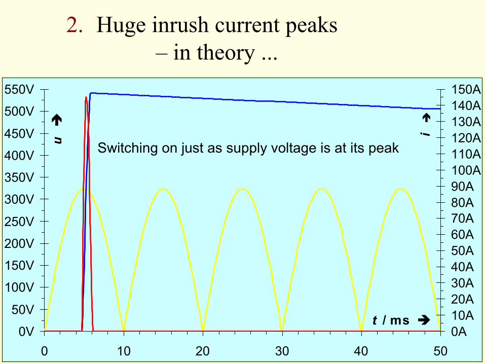
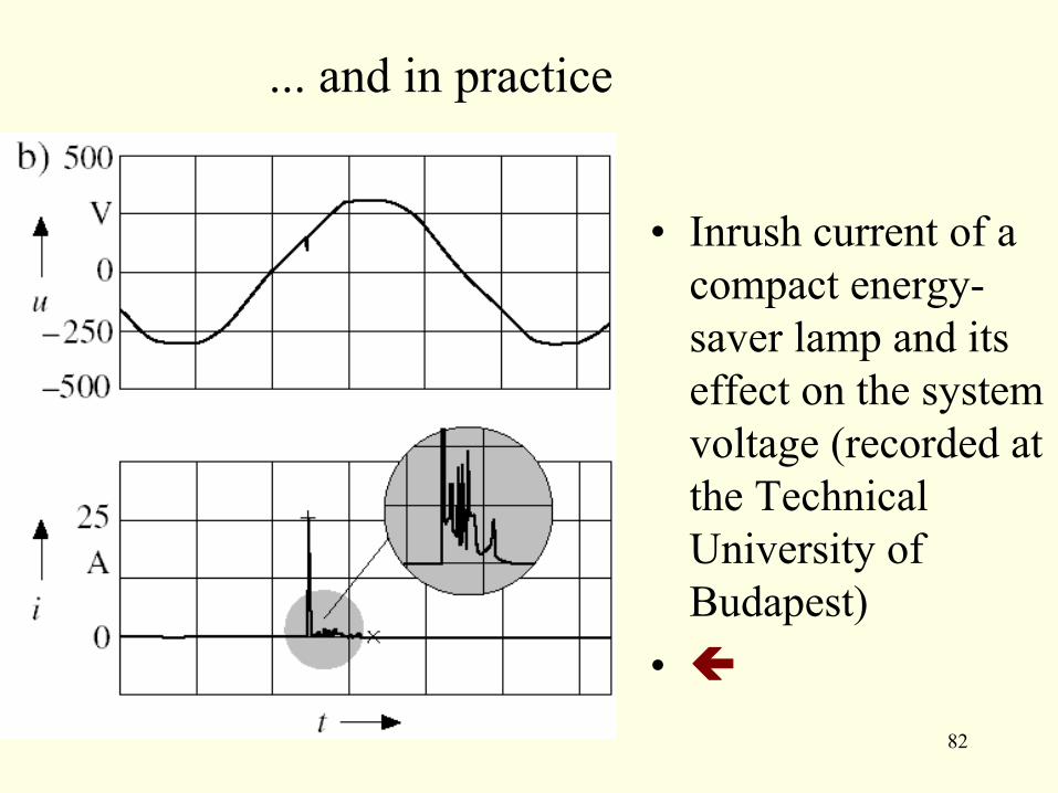
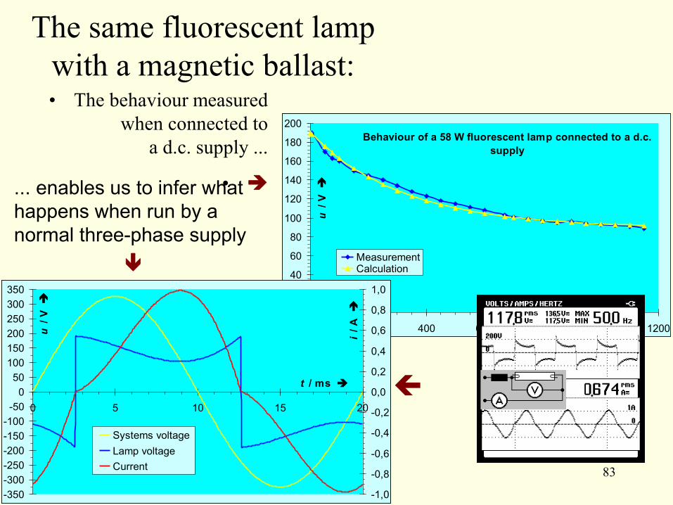
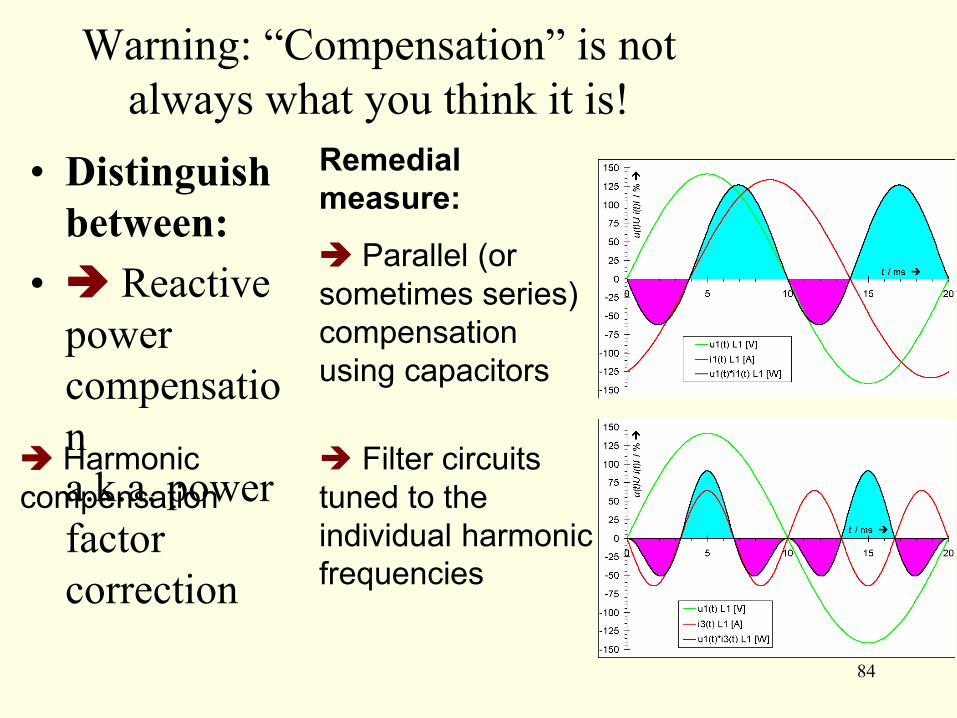
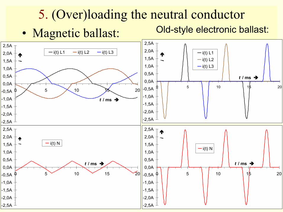
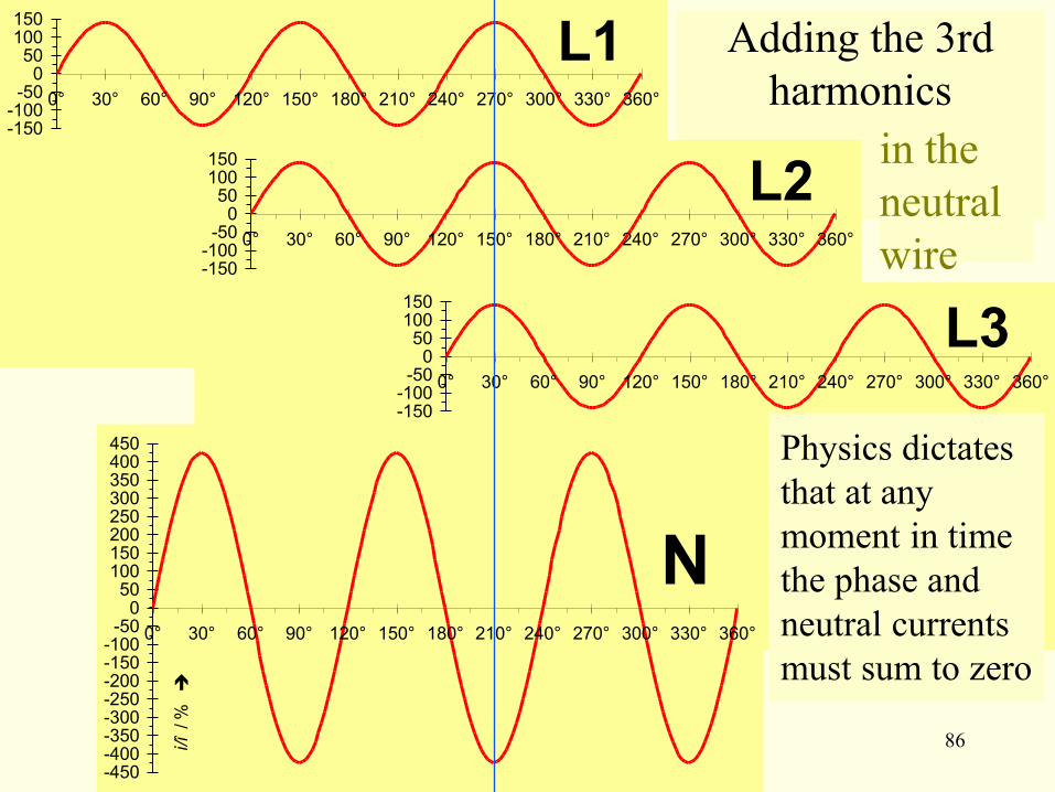
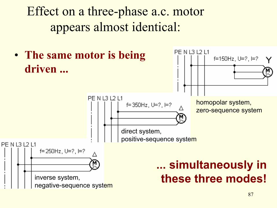
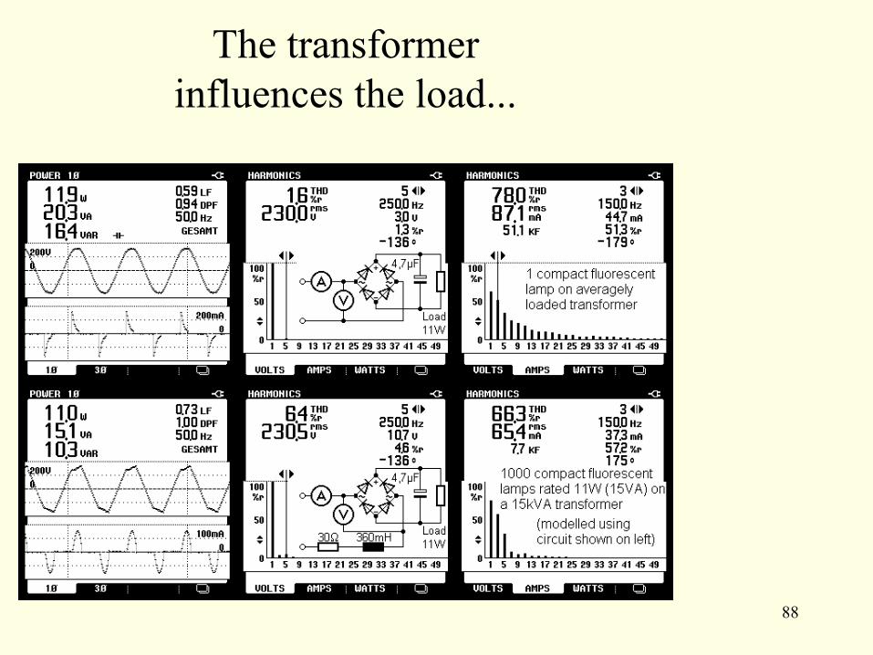
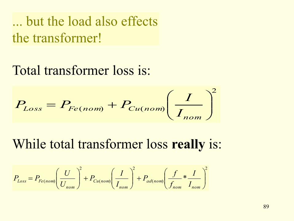
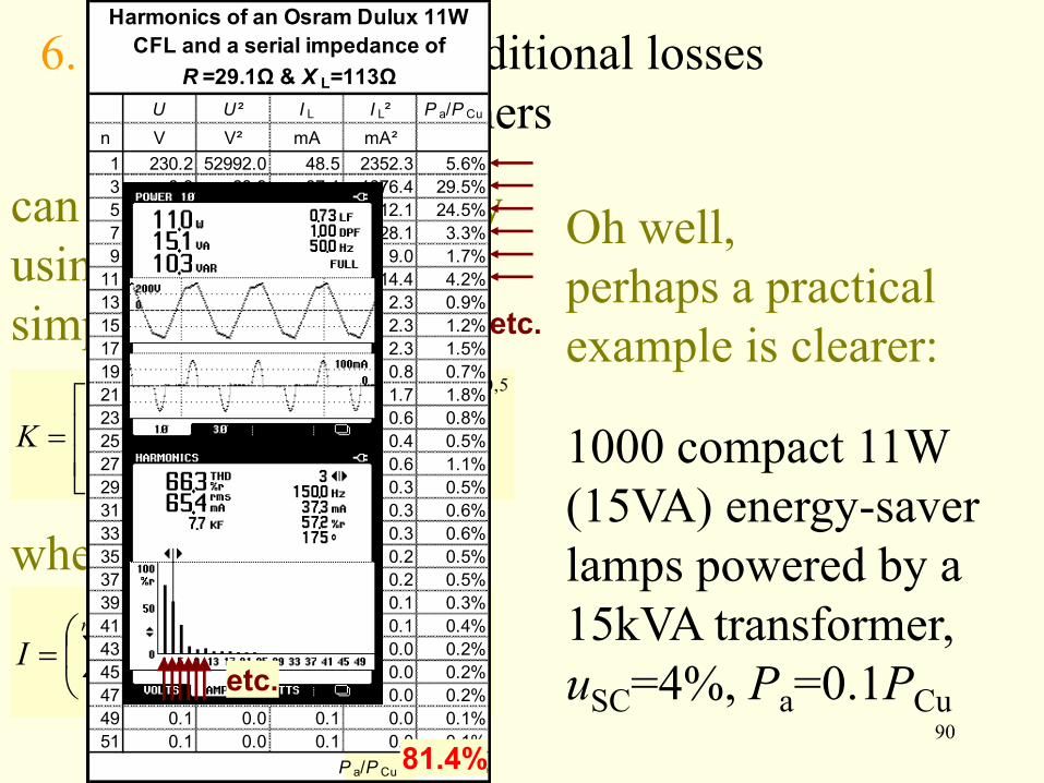
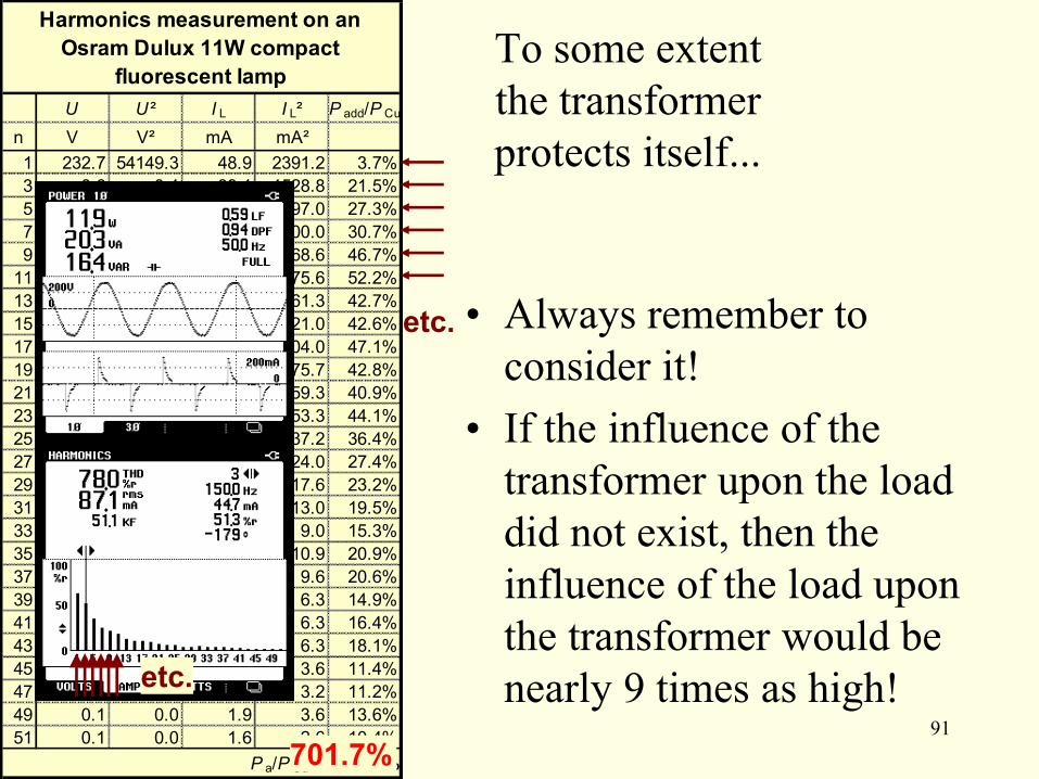
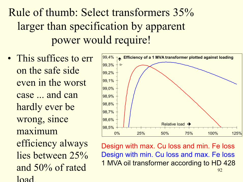
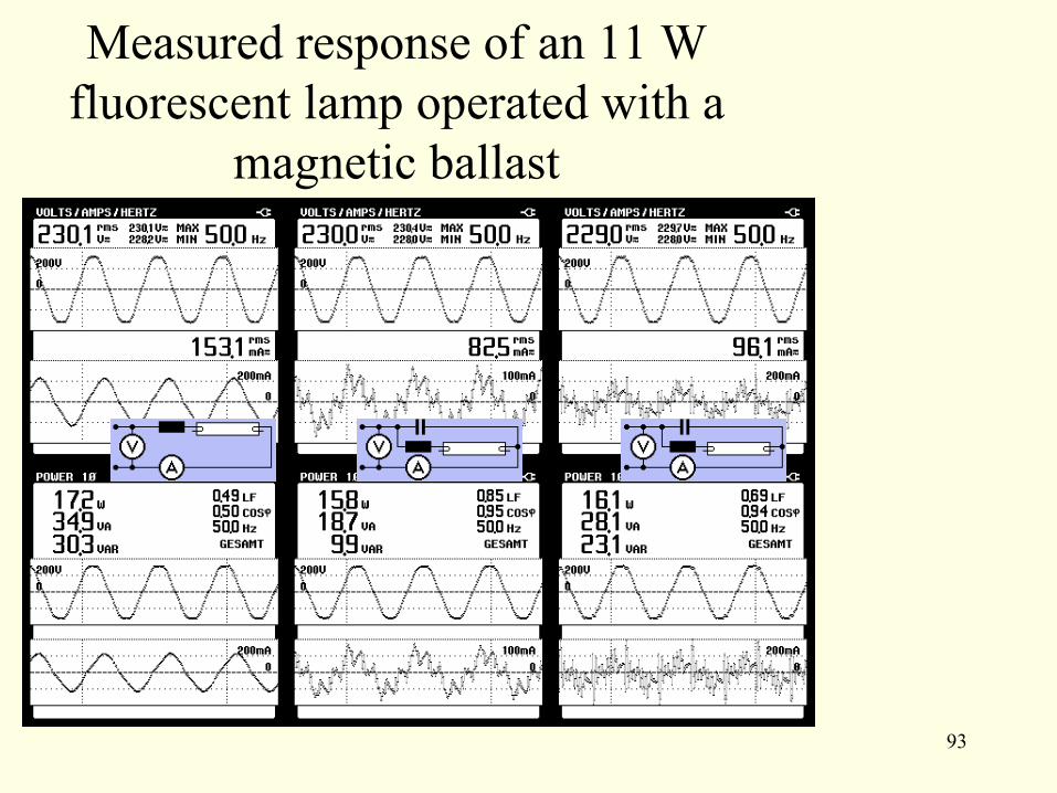
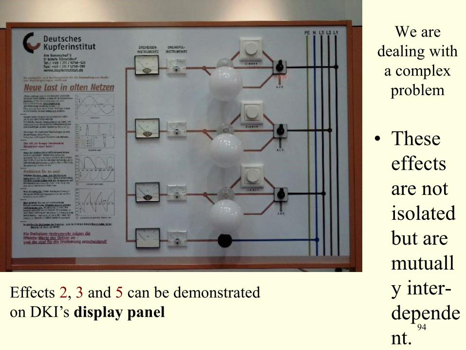
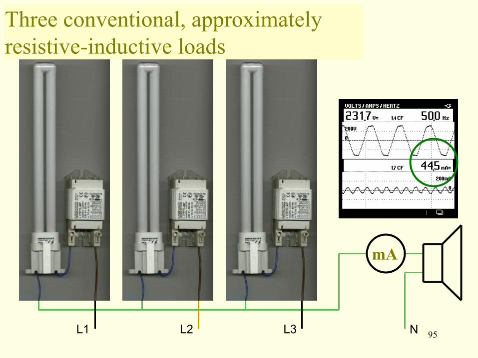
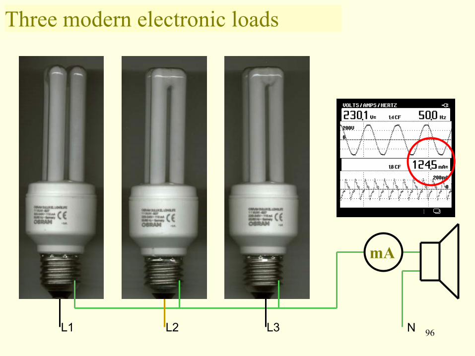
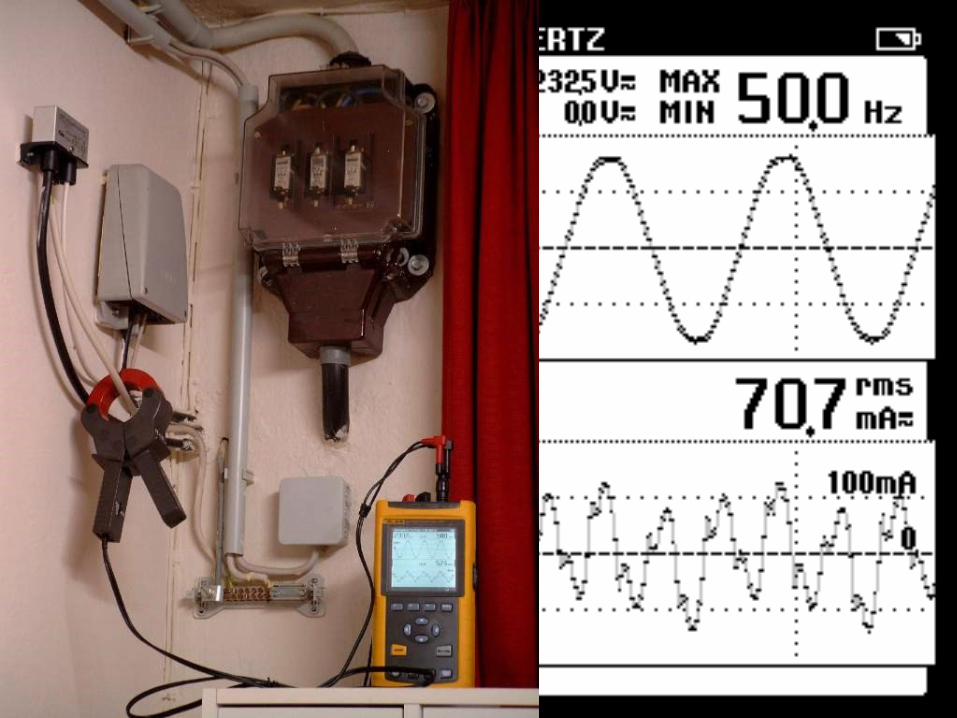
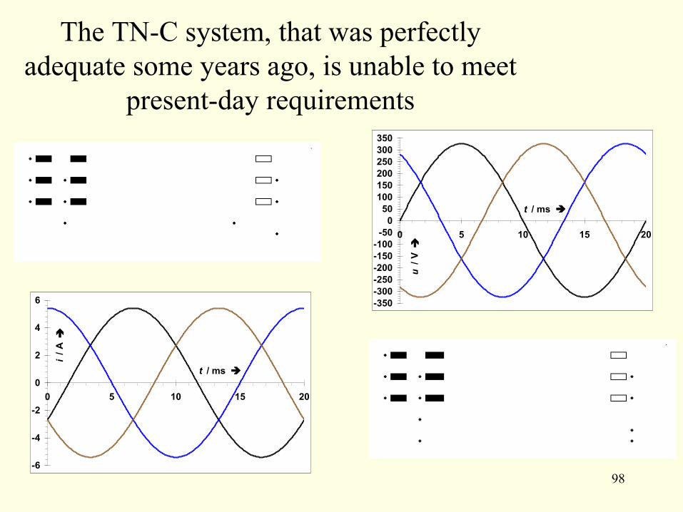
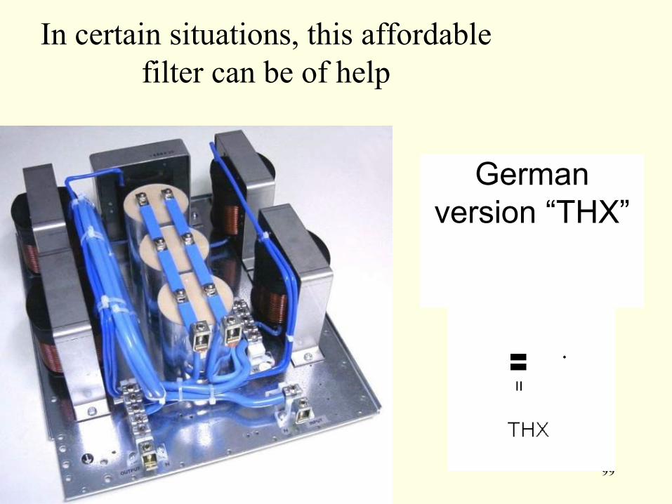
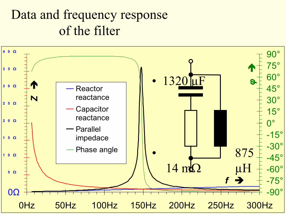
100
0Ω
5 Ω
1 0 Ω
1 5 Ω
2 0 Ω
2 5 Ω
3 0 Ω
3 5 Ω
4 0 Ω
0Hz 50Hz 100Hz 150Hz 200Hz 250Hz 300Hz
f
Z
-90deg
-75deg
-60deg
-45deg
-30deg
-15deg
0deg
15deg
30deg
45deg
60deg
75deg
90deg
φ
Reactorreactance
Capacitorreactance
Parallelimpedace
Phase angle
Data and frequency response
of the filter
bull 1320 microF
bull 875
14 mW microH
101
The filter in use
bull In a nursery running sodium vapour lamps (500 kW)
In a typical office and administrative building
102
The EMC Transformer from Switzerland
7 The effects of stray magnetic fields
in TN-C systems
bull ldquoWhen we build transformers the first thing we focus on is complying with our customersrsquo
requirements and only then on complying with standards Why Because it is customer
needs and not standards that offer real scope for product innovationrdquo
103
8 In a TN-C system problems arise from data
streams and working currents mixing
bull Others who
have drawn
attention to
this source of
data
transmission
errors include
engineering
and insurance
companies experts
consultants and many
others besides
104
9 Increased corrosive damage
bull This (once) galvanized steel strip ndash the earth
electrode of a TN-C-S system ndash was located close
to the transformer station
Side facing
transformer
station
Side facing
transformer
station
Side facing away
from transformer
station
Side facing away
from transformer
station
105
bull WRONG RIGHT
Working currents have no place
in earthing systems and
protective conductors
106
10 Lightning currents
107
Which bridge to
cross which bridge to
burn
Sometimes you just donlsquot
believe what you see
This one will soon
look rather charred
IEC 60364-5-54
54343 If from any point of the installation the neutral and protective
functions are provided by separate conductors it is not permitted to
connect the neutral conductor to any other earthed part of the
installation
108
Well then the rest is no longer a
miracle
109
110
111
Another means of (over)loading the
neutral conductor
bull dc currents
Original ldquoFakerdquo
112
and their
effects U = 2285 V
I = 92 mA
P = 182 W
S = 209 VA
Q = 103 VAr
LF = 087
cos φ = 099
U = 2243 V
I = 126 A
P = 380 W
S = 2860 VA
Q = 2830 VAr
No-load current in a
toroidal-core
transformer
200 VA
-350-300
-250-200
-150-100
-500
50
100150
200250
300350
0 10 20 30 40
t ms
u
V
-12
-10
-8
-6
-4
-2
0
2
4
6
8
10
12
i
mA
Voltage
Current
No-load current in a toroidal-core
transformer 200 VA when
running a 1500 W
hairdryer at
half-power
in parallel
-350-300
-250-200
-150-100
-500
50
100150
200250
300350
0 5 10 15 20 25 30 35 40
t ms
u
V
-6
-5
-4
-3
-2
-1
0
1
2
3
4
5
6
i
A
Voltage
Current
113
The later models donlsquot do it any more
The EN 61000-3-2 has at least managed
to put an end to this approach
Domestic appliances Max 105 A of 2nd harmonic
114
An electrical engineering wonder
dc current generates ac voltage
115
Spicing things up with a pinch of HF
electronic halogen lamp transformers
116
Decorative HF reactors
117
Current and power loss as a function of voltage
00
02
04
06
08
10
12
14
16
18
0 40 80 120 160 200 240
U V
I
A
0
20
40
60
80
100
120
PV
W
I [A]
Pv [W]
Power loss capacitor voltage
and total voltage as a function of current
0
50
100
150
200
250
300
350
400
450
000 025 050 075 100 125 150
I A
U
V
0
5
10
15
20
25
30
35
40
45
50
PV
W
Utot [V] Eff
UR [V] Eff
Pv [W]
The passive
harmonic filter
made of readily
available
components
bull is both
reliable
118
and effective
bull befor
e
bull after
119
Half the solution has already been implemented
120
And if thatrsquos not enough
bull Passive filter circuits will do it
121
So what do we need to do
bull In low-voltage power distribution systems
Do not use cables in which the neutral or protective earth conductor has a
reduced cross-section
Use only 5-core cable Do not install TN-C- or TN-C-S systems
Be generous when dimensioning conductor cross-sections This helps to
reduce line voltage drops and thus reduces the effect of current distortions on
the voltage as well as lowering energy losses (see VDE 0298 Part 100)
Generously dimensioned conductors will have no problem coping with any
future increase in demand
Only use measuring instruments that display the true root mean square value
(TRMS meters)
In medium-voltage power distribution systems
Use a varied mix of distribution transformers with different vector groups
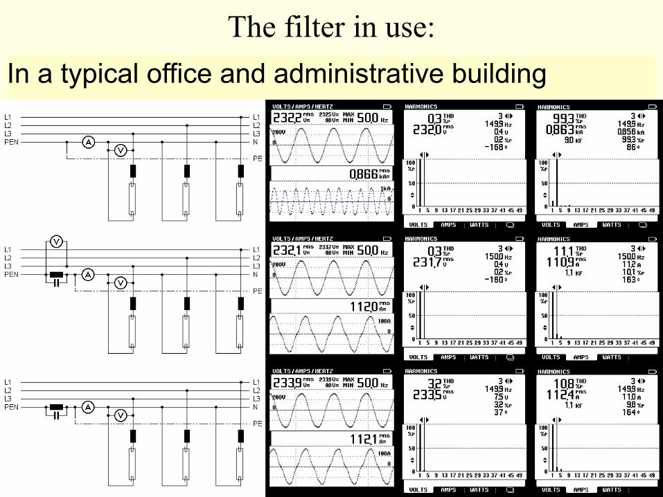
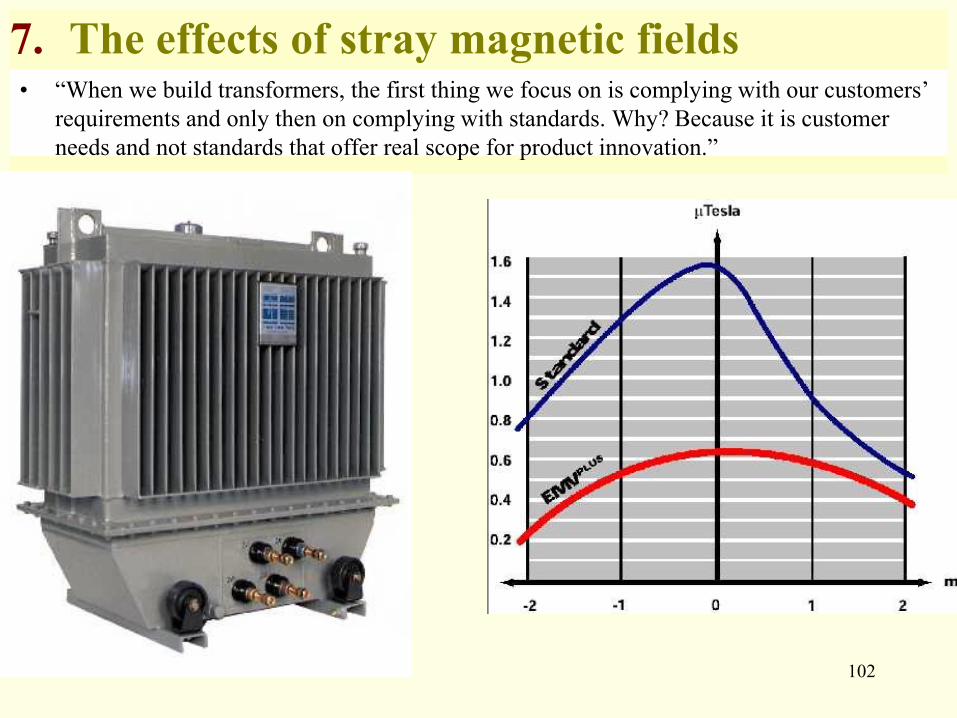
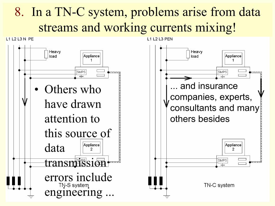
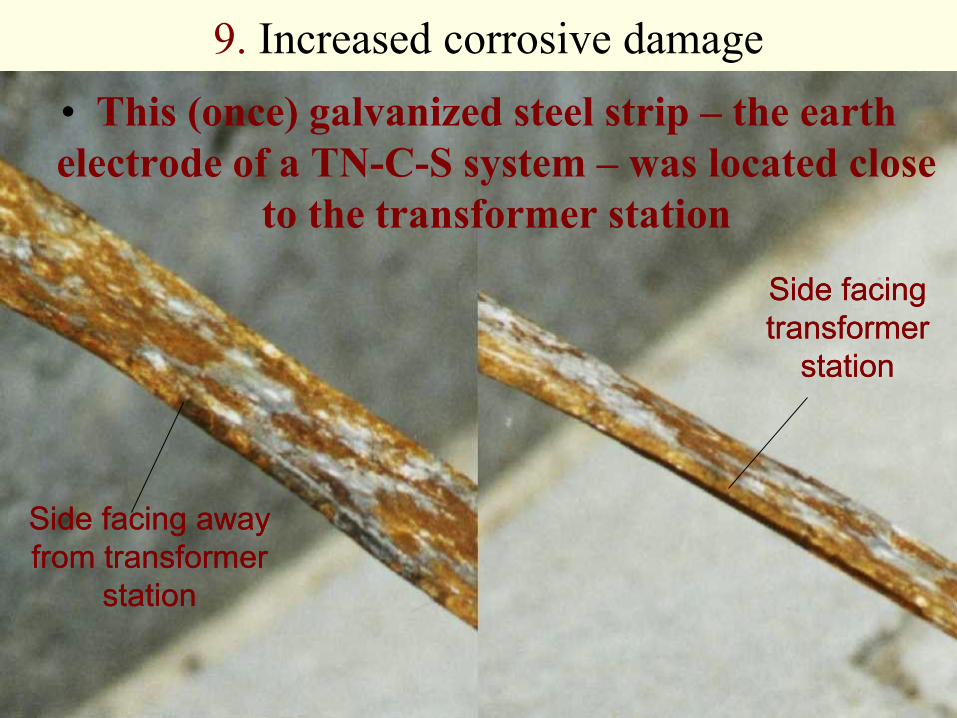
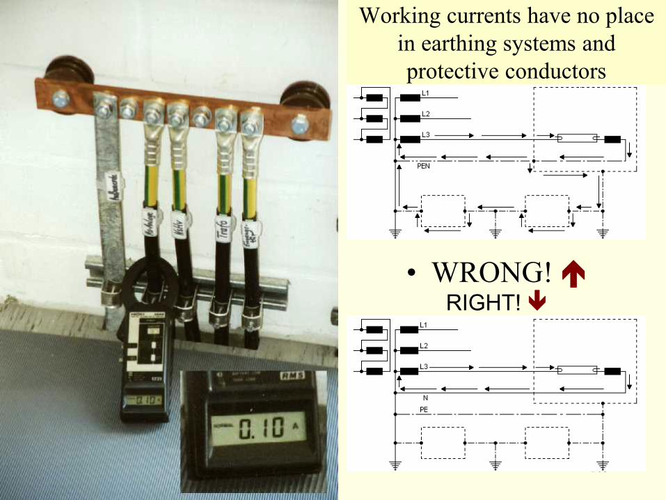
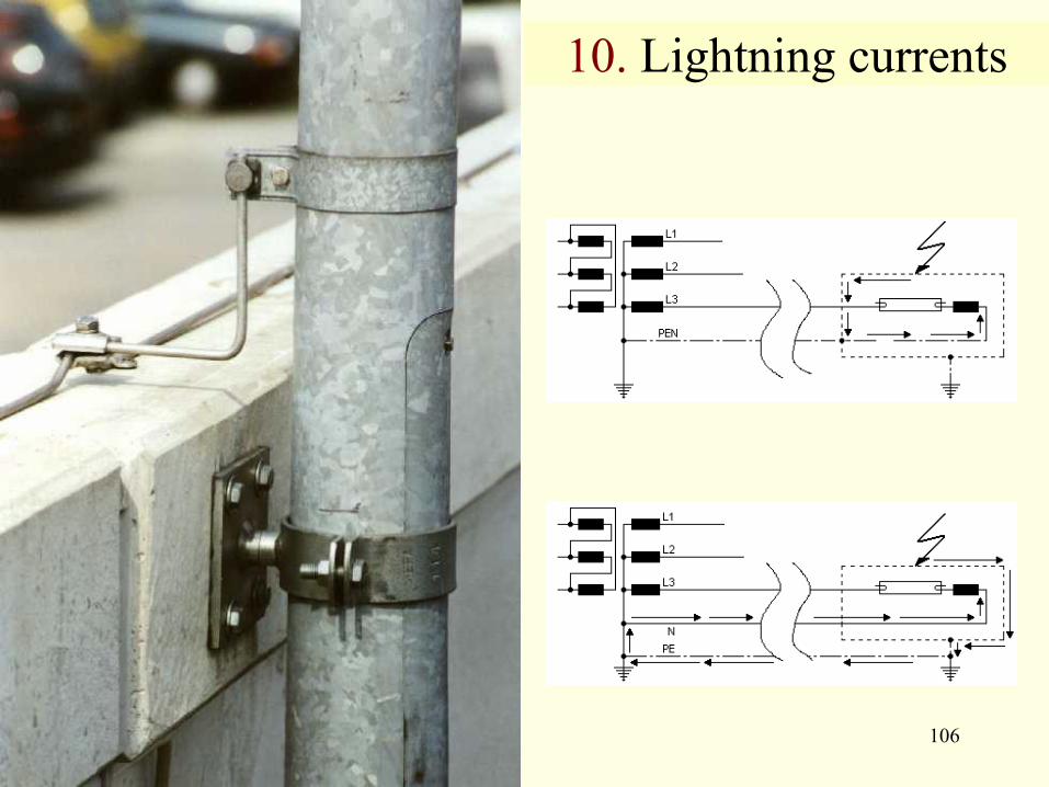
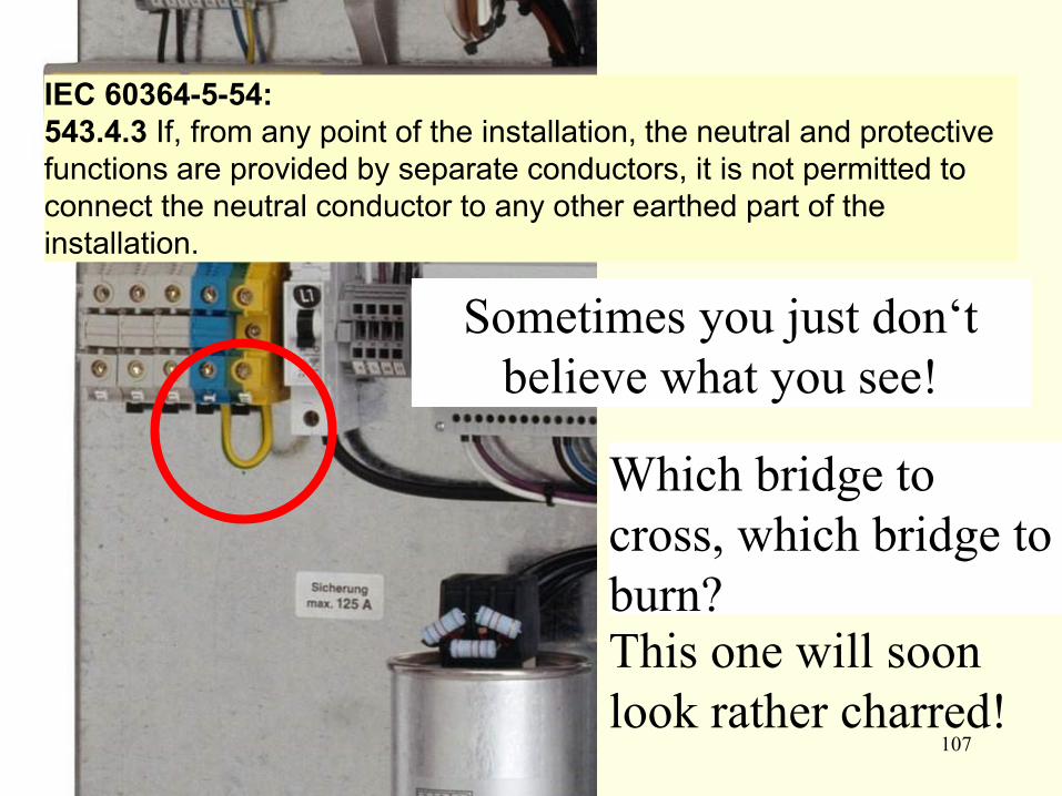
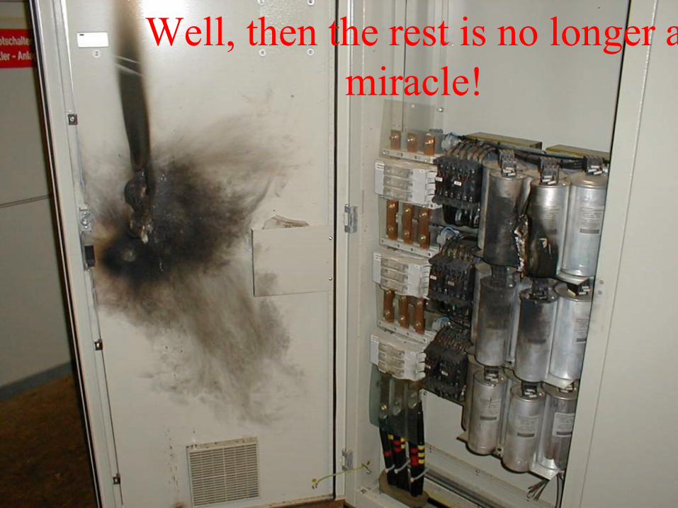
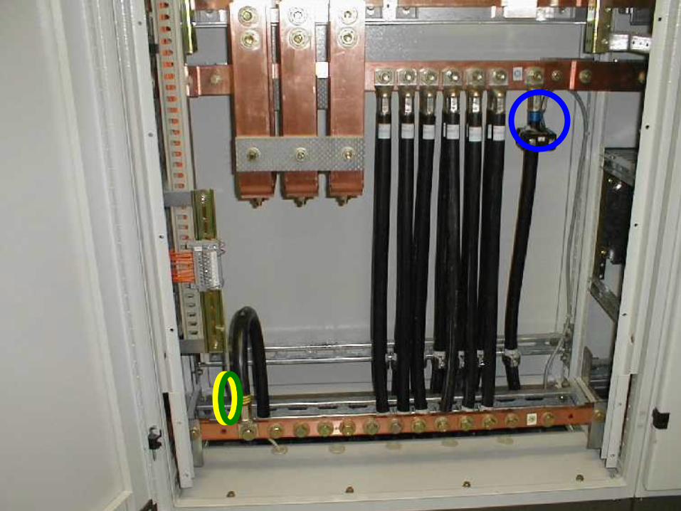
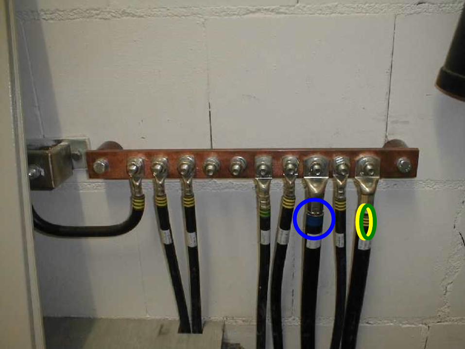
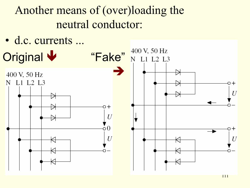
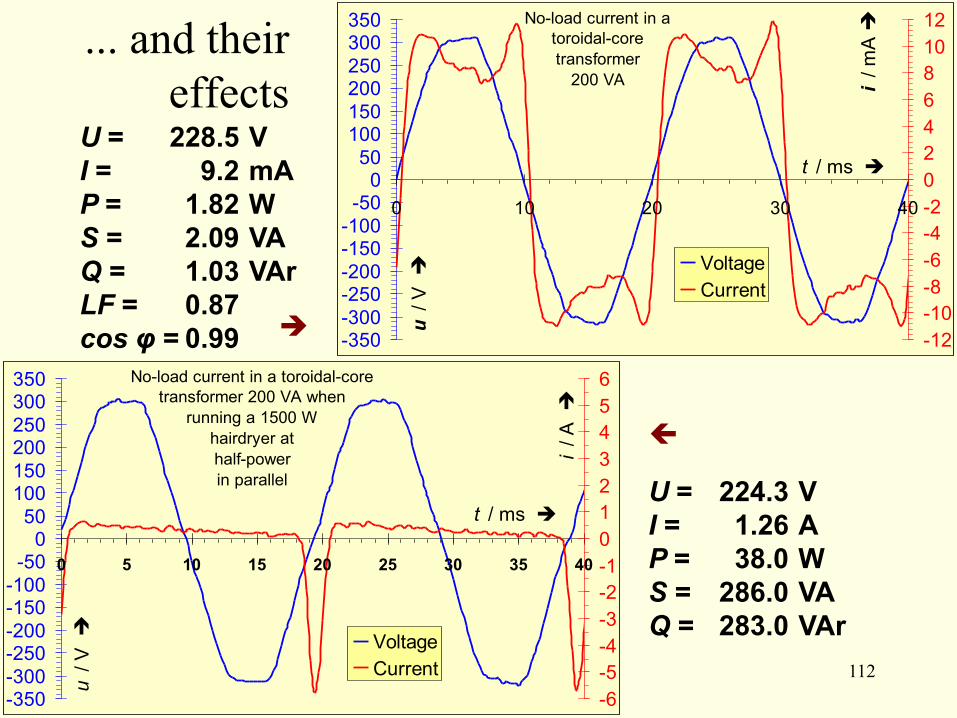
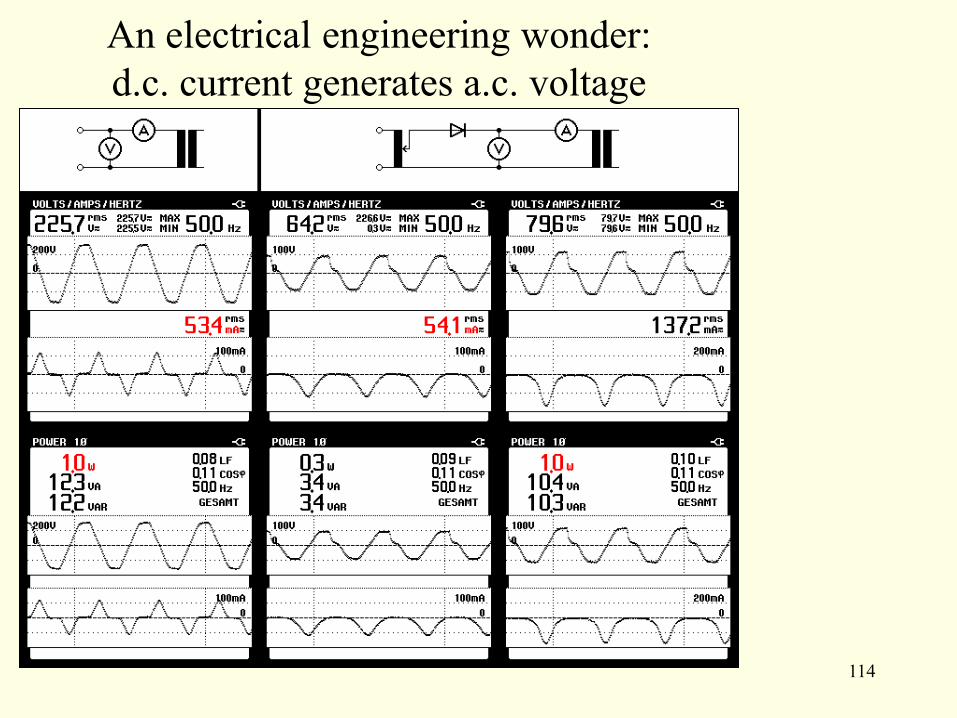
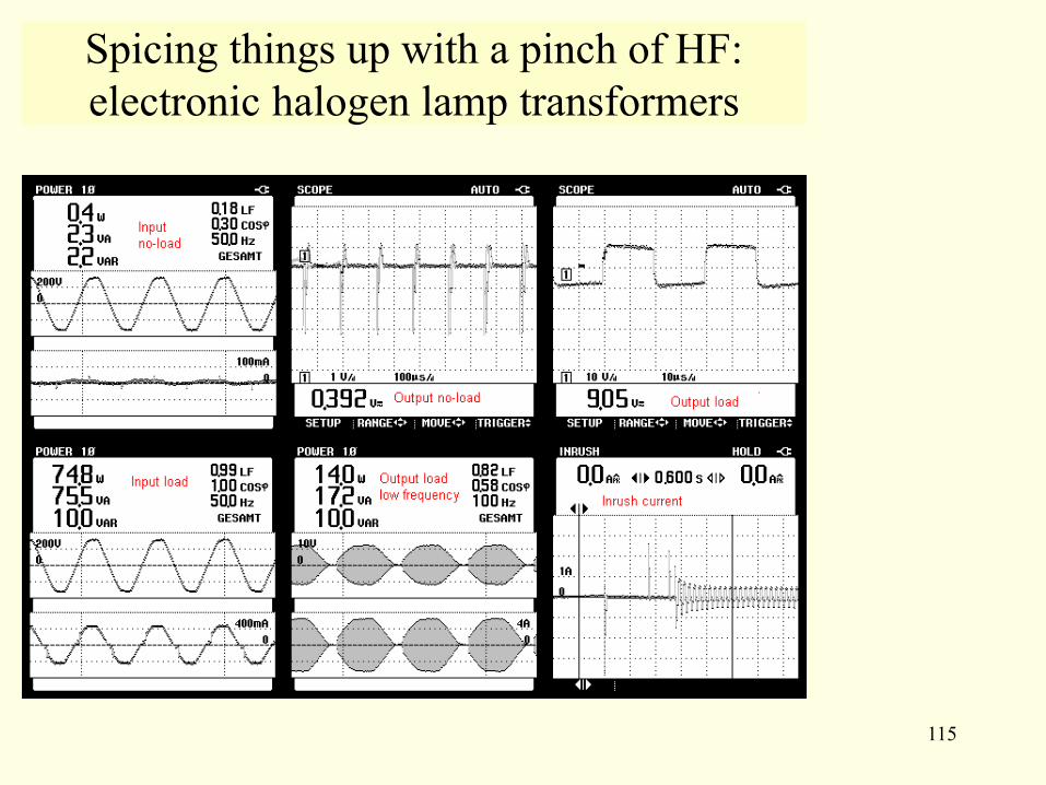
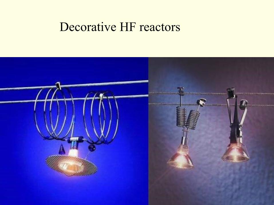
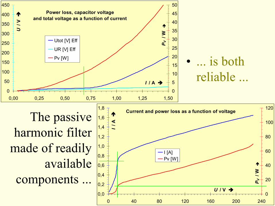
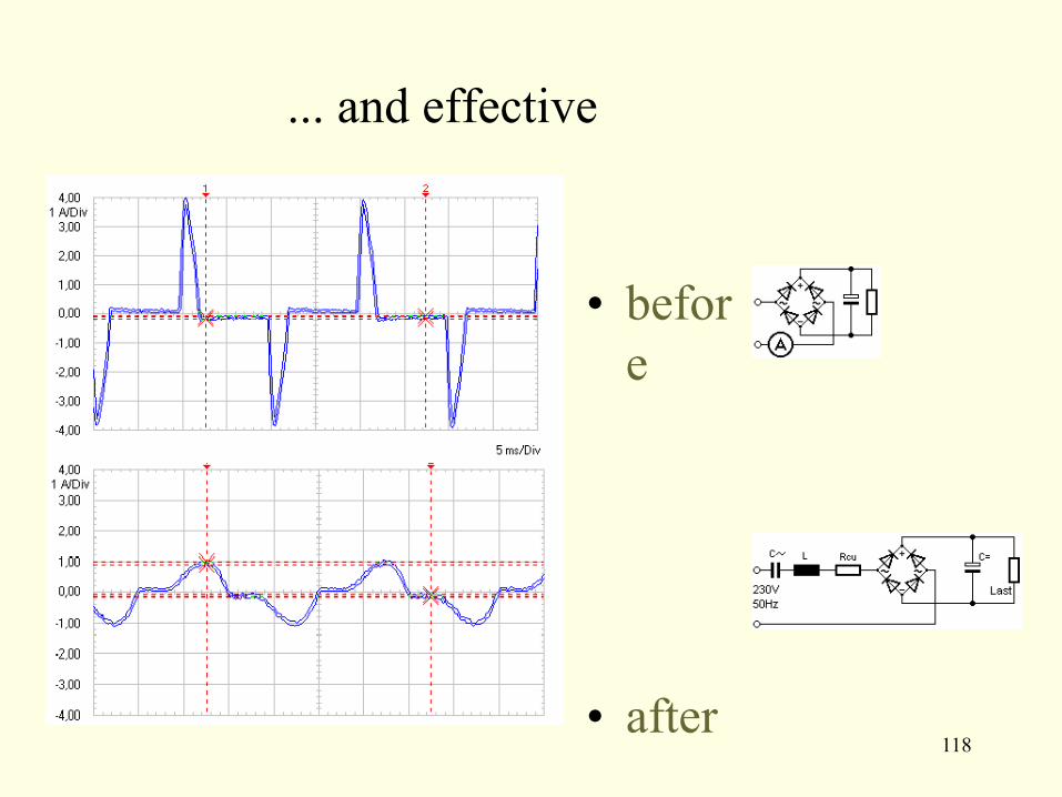
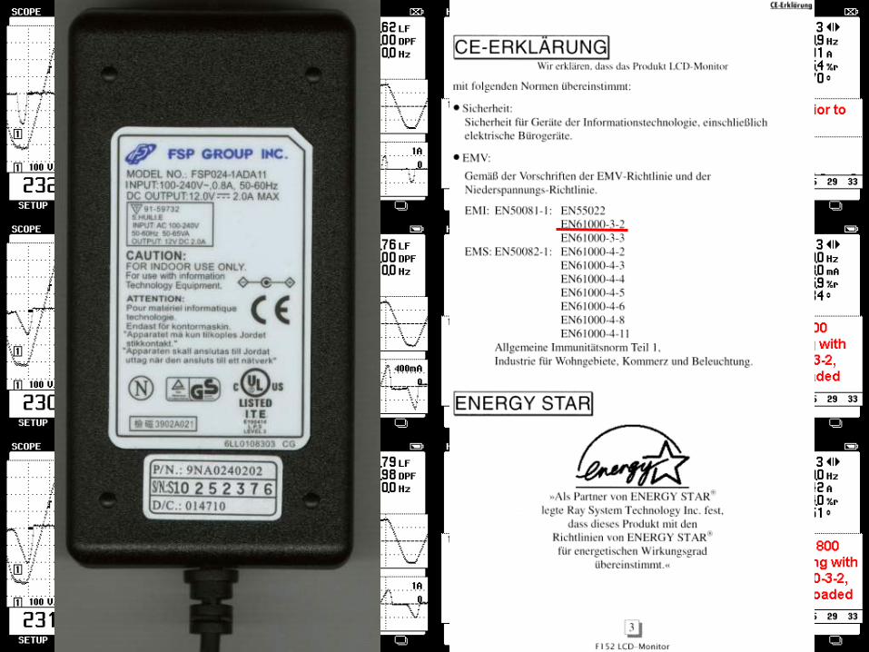
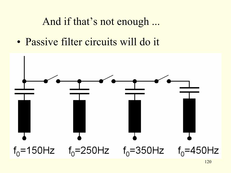