Embed Size (px)
Citation preview
promoting access to White Rose research papers
White Rose Research Online [email protected]
Universities of Leeds, Sheffield and York http://eprints.whiterose.ac.uk/
This is an author produced version of a paper published in Journal of Materials in Civil Engineering. White Rose Research Online URL for this paper: http://eprints.whiterose.ac.uk/42806
Published paper Neocleous, K., Tlemat, H., Pilakoutas, K. (2006) Design issues for concrete reinforced with steel fibers, including fibers recovered from used tires, Journal of Materials in Civil Engineering, 18 (5), pp. 677-685 http://dx.doi.org/10.1061/(ASCE)0899-1561(2006)18:5(677)
Materials in Civil Engineering (ASCE) Journal
Paper Ref. MT/2004/022927 – Accepted Manuscript 1
Design Issues for Concrete Reinforced with Steel Fibers, Including Fibers Recovered from Used
Tires
K. Neocleous1, H. Tlemat 2 and K. Pilakoutas3
1 Post -d octor al Resear ch Associate, Cen t r e for Cem ent an d Concr ete, Dep t . of
Civ i l & St r uctu r al En gin eer in g, Un iv . of Shef f ield , Sh ef f ield , S1 3JD, UK,
k .n eocleous@shef f ield .ac.uk
2 Senior Engineer, Buro Happold, 49 Newhall Street, Birmingham, B3 3QR, UK, [email protected] 3 Pr ofessor of Const r uct ion In novat ion , Cen t r e for Cem ent an d Con cr ete, Dep t .
of Civ i l & St r uctu r al En gin eer in g, Un iv . of Sh ef f ield , M app in St r eet , Shef f ield ,
S1 3JD, UK. K.p i lakou tas@shef f ield .ac.uk , Tel . +44-114-225065, Fax +44-114-
2225700
Materials in Civil Engineering (ASCE) Journal
Paper Ref. MT/2004/022927 – Accepted Manuscript 2
Abstract: The authors are investigating the use of steel fibers, recovered from used tires (RSF), as
concrete reinforcement, aiming at the development of design recommendations. This paper presents
part of this research and examines initially an existing design guideline, developed by RILEM for
steel fiber-reinforced concrete (SFRC), in order to assess the suitability of the guideline for the
flexural design of concrete reinforced with RSF (RSFRC). This examination indicates that, although
the RILEM guideline is in general suitable for the flexural design of RSFRC, there are some
fundamental issues related to the evaluation of the tensile stress-strain behavior of SFRC that affect
the accuracy of the guideline. Thus, based on this conclusion, a new approach is outlined for the
evaluation of the tensile stress-strain behavior of SFRC and models are derived for different types of
RSF and industrially-produced fibers. These models are applied to the flexural design of concrete
reinforced with RSF (RSFRC) and results are compared with those obtained by using the RILEM
tensile stress-strain models. It is concluded that the model proposed in this study is more conservative
and accurate than the RILEM models. Recommendations are also made on values of tensile strain to
be used as ultimate limit state, when predicting the resistance-capacity of SFRC and RSFRC.
CE Database subject headings: waste utilization, tires, steel fibers, concrete properties, structural
design, flexural strength.
Introduction
A recently-filed patent (University of Sheffield 2001) claims that RSF can be used as fiber
reinforcement to enhance the flexural strength and ductility of concrete. The use of RSF as
reinforcement in concrete will benefit the environment, since the fibers are currently a waste arising
from the recycling of tires. However, the lack of a general design framework and simple design
guidelines for concrete reinforced with RSF is perceived as one of the main barriers to the use of RSF
in concrete construction. Although the flexural behavior of RSFRC is similar to that of conventional
SFRC (Tlemat 2004), it is not certain whether existing design guidelines, developed specifically for
SFRC, can be successfully applied for the flexural design of RSFRC. Therefore, the authors deemed
necessary to examine these guidelines in order to assess their suitability for RSFRC and, if necessary,
to propose appropriate modifications to the guidelines.
Materials in Civil Engineering (ASCE) Journal
Paper Ref. MT/2004/022927 – Accepted Manuscript 3
The research reported in this paper was undertaken as part of a comprehensive investigation on
the use of RSF in concrete construction (DTI 2001, European Commission 2002, Tlemat 2004), and
aimed at the development of a general framework for design, as well as simple design guidelines for
the effective use of RSF in concrete construction.
Initially, one of the RILEM guidelines recommended for the design of SFRC (RILEM 2000) is
examined and an attempt is made to analyze the design philosophy behind it by considering the
findings of a European project (Brite-Euram, 2002) on conventional SFRC as well as the results,
obtained by the authors, on the flexural behavior of both RSFRC and SFRC. This involves the
examination of a number of design issues that are relevant to the guideline, such as the accuracy of the
design procedure, the type of bending test utilized for the evaluation of the flexural tensile strength
and the derivation of the tensile stress block.
The tensile stress-strain model developed as part of the above research (Tlemat 2004) is also
presented, and an attempt is made to predict the flexural behavior of SFRC and RSFRC prisms by
using the proposed model and models obtained from the RILEM guidelines. The designs are
compared with results obtained experimentally (Tlemat et al. 2005), and recommendations are made
about deformation limits and tensile strains to be used for the limit-state design of different types of
SFRC and RSFRC elements.
RILEM stress-strain design guideline for SFRC
The stress-strain (σ-ε) design guideline for SFRC was published by the RILEM technical
committee on “test and design methods of steel fiber reinforced concrete” (RILEM 2000). This
guideline is similar to previous design guidelines for SFRC developed for a specific type of industrial
fibers (Nemegeer 1996). The guideline utilizes the design framework of Eurocode 2 (ENV 1992) and
it contains design provisions for the ultimate limit-states of flexure and shear, as well as for the
serviceability limit-state of cracking.
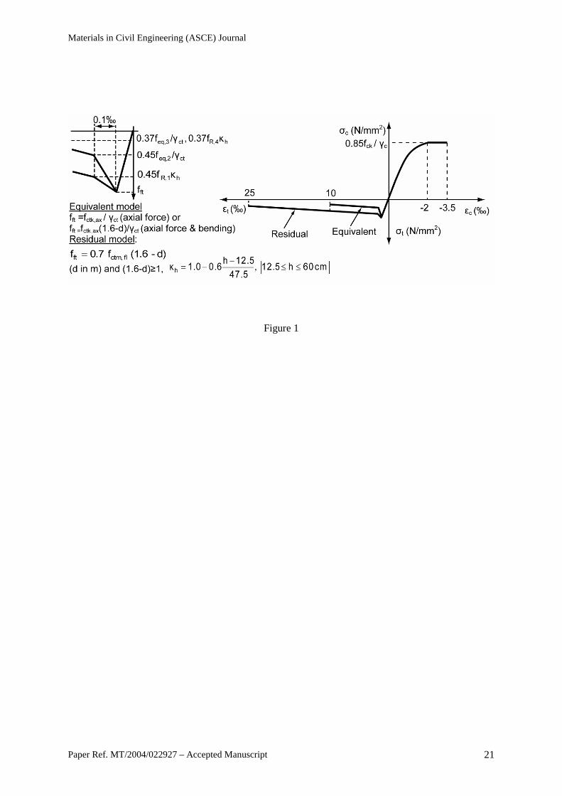
Fig. 1 shows the σ-ε relationship adopted for SFRC by the σ-ε guideline. The compressive part
of the σ-ε relationship is defined by using the model adopted by Eurocode 2 for plain concrete. The
tensile part of the σ-ε relationship is described in terms of the SFRC axial tensile strength and the
SFRC equivalent flexural tensile strengths feq,2 and feq,3. The ultimate tensile strain adopted by the
Materials in Civil Engineering (ASCE) Journal
Paper Ref. MT/2004/022927 – Accepted Manuscript 4
model is 10‰. The axial tensile strength of SFRC can be calculated from either the load at the limit of
proportionality (LOP) or the compressive strength of SFRC. The equivalent flexural tensile strengths
are post-cracking average stresses, derived from the energy-absorption capacities DfBZ,2 and Df
BZ,3
(equations 1 and 2). DfBZ,2 aims to represent the average flexural capacity just after cracking, whilst
DfBZ,3 is the average flexural capacity for the entire post-cracking region up to just before failure.
DfBZ,2, used to derive feq,2, is the area under the load-deflection curve between the deflection at the
LOP (δLOP) and a deflection of δLOP plus 0.65 mm, whilst for feq,3, the energy-absorption capacity
DfBZ,3 is calculated as the area under the load-deflection curve between δLOP and a deflection of δLOP
plus 2.65 mm (RILEM 2000). A new model for the tensile σ-ε relationship, also shown in Fig. 1, was
recently developed on the basis of the SFRC axial tensile strength, the residual flexural tensile
strengths (fR,1 and fR,4) and the ultimate tensile strain of 25‰ (Brite-Euram 2002, RILEM 2003). The
residual flexural tensile strengths are post-cracking stresses calculated at different locations of the
SFRC load-deflection curve (equation 3); fR,1 is calculated at a mid-span deflection of 0.46 mm or a
crack-mouth-opening-displacement (CMOD) of 0.5 mm; fR,4 is calculated at a mid-span deflection of
3 mm or a CMOD of 3.5 mm (RILEM 2003).
2
fBZ,2
eq,2 bhL
0.50D
23f
= (1)
2
fBZ,3
eq,3 bhL
2.50D
23f
= (2)
2i
iR, bhLF
23f = (3)
The accuracy of both σ-ε guidelines (RILEM 2000, RILEM 2003) is an important issue for
discussion. A recently-completed study on SFRC (Brite-Euram 2002) reports that the 2000 RILEM σ-
ε guideline, based on the equivalent-strength model, overestimates the flexural resistance of deep
beams. This was particularly observed for SFRC beams that did not contain any conventional steel
reinforcement (Erdem 2003). In addition, Erdem pointed out that, for SFRC beams containing
conventional reinforcement, this inaccuracy increases with the fiber content (Vf). The Brite-Euram
Materials in Civil Engineering (ASCE) Journal
Paper Ref. MT/2004/022927 – Accepted Manuscript 5
study consequently proposed the use of reduction factors on the values of feq and fR. It is noted that
these reduction factors are defined as a function of the element’s depth. A similar reduction factor (κh)
accounting for size-effect is also proposed in RILEM (2003), as shown in Fig. 1.
Erdem (2003) also pointed out that, in addition to the size-effect, the flexural resistance is not
accurately predicted because the behavior of SFRC elements is modeled by the same tensile stress-
strain relationship irrespective of Vf. Furthermore, Erdem argues that the effectiveness of the fibers,
and consequently the flexural resistance of SFRC, is influenced by the orientation of the fibers (η),
which in turn is affected by the depth of the element. Hence, Erdem proposes that the RILEM stress-
strain model should be modified for each design case by using reduction factors, which are
probabilistically-derived as a function of both Vf and element size.
The procedure adopted to define the general shape of the RILEM tensile stress-strain curve is
another source of inaccuracy. As illustrated in Fig. 1, the shape of this curve is defined by equivalent-
strength and residual-strength constants (0.45 for feq,2 and fR,1, and 0.37 for feq,3 and fR,4). These stress
constants are determined on the basis of equivalent elasto-plastic stress diagrams, by assuming
specific values for the neutral axis depth (RILEM 2003). Although this approach seems reasonable, it
is not entirely appropriate for the derivation of general stress-strain relationships. This is because, in
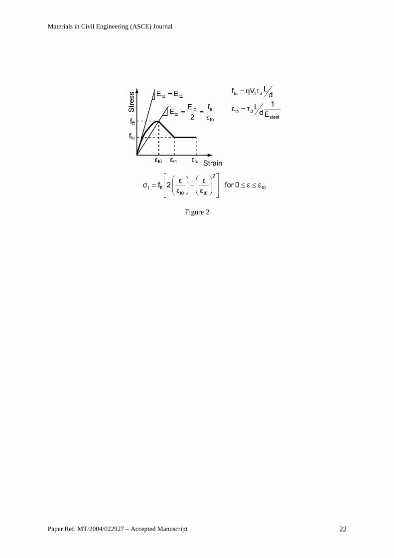
addition to Vf and fiber orientation within the element (Erdem 2003, Tlemat 2004), the position of the
neutral axis and the shape of the tensile stress-strain curve are affected by the material characteristics
of the fibers (such as aspect ratio L/d and bond strength τd). Depending on these characteristics, an
SFRC element may exhibit flexural strengthening or softening (Lok and Xiao 1999). Thus, the tensile
stress-strain model developed for SFRC by Lok and Xiao (Fig. 2) may be more appropriate for
codified design of SFRC, since this model takes into account all these characteristics. An attempt to
apply this model for the design of RSFRC has indicated that it is not possible to accurately apply the
model for the case of RSF (especially for those extracted from tire shredding). This is mainly
attributed to the variable geometry of the fibers (Neocleous et al. 2004).
As mentioned above, the application of the σ-ε design guideline requires the evaluation of
general material properties of SFRC, such as feq and fR, which are essential for the characterization of
the post-cracking flexural behavior of SFRC. These material properties are in general determined by
Materials in Civil Engineering (ASCE) Journal
Paper Ref. MT/2004/022927 – Accepted Manuscript 6
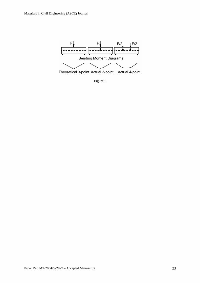
carrying out deformation-controlled bending tests on SFRC prisms. The σ-ε design guideline uses a
deformation-controlled bending test with a three-point bending load arrangement (RILEM 2002,
Vandewalle and Dupont 2003). This load arrangement overestimates the flexural resistance of the
element due to load spreading, which occurs at the point of load application (Timoshenko and
Goodier 1970). Hence, it may be more appropriate to use a four-point bending load arrangement for
the evaluation of the flexural resistance, as this decouples the load spreading effect and creates a
region of constant moment (Fig. 3).
The definition of the LOP (the point on the load-deflection curve where cracking initiates) is
essential for the calculation of feq and, hence, accuracy problems may be encountered when evaluating
this limit. Similar to other design guidelines, the bending test (RILEM 2002) adopted by the σ-ε
guideline defines LOP as the point of maximum load within a predefined deflection interval (RILEM
uses the interval between 0 and 0.05 mm). This approach for defining the LOP is prone to mistakes,
since initial errors in experimental measurements are often eliminated subjectively. It is noted that the
recently-completed Brite-Euram project on SFRC (Brite-Euram 2002a) proposes the use of a more
objective method, where the LOP is defined through an iterative procedure, whose aim is the
evaluation of the correct slope at the limit of proportionality.
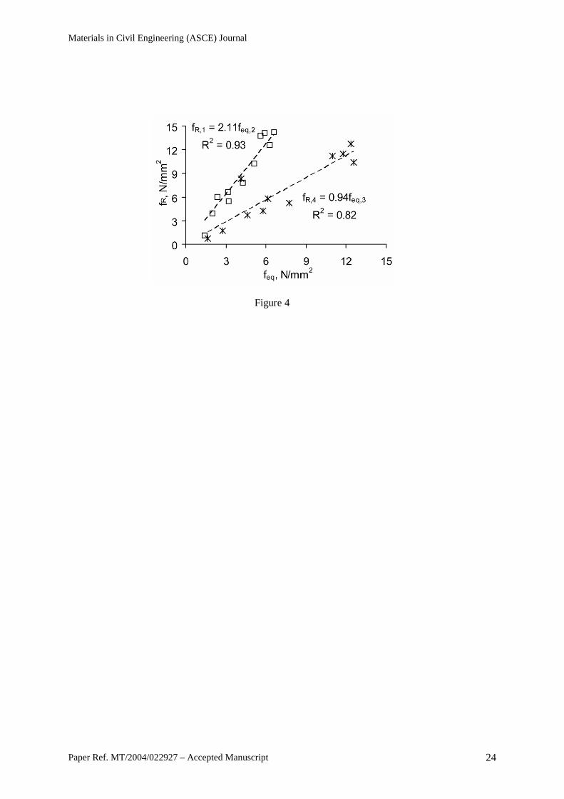
The introduction of the RILEM tensile σ-ε model, based on fR, is intended to eliminate the
subjectivity of removing initial errors in experimental measurements, since this model uses CMOSs,
which can be measured more accurately. The difference between residual strengths and equivalent
strengths is illustrated in Fig. 4 for experiments undertaken by the authors using the “yoke” specified
by the Japanese standard for the deflection measurements (Tlemat 2004, JSCE 1994). The values
calculated for the residual strength fR,1 and equivalent strength feq,2, though not similar, have a high
degree of correlation. This means that, although the method is radically different leading to a much
higher residual strength value, displacement measurements taken using the “yoke” appear to be as
reliable as the CMODs. The values of the residual strength fR,4 and equivalent strength feq,3 are similar,
since the accuracy of feq,3 is not affected much by any initial errors in experimental measurements.
The introduction of the residual-strength σ-ε model is a conceptual improvement on the
equivalent-strength σ-ε model, since it provides a measure of stress rather than a measure of ductility.
Materials in Civil Engineering (ASCE) Journal
Paper Ref. MT/2004/022927 – Accepted Manuscript 7
It is noted that to arrive at σ-ε models, both design approaches (RILEM 2000, RILEM 2003) need
experimental data for every different parameter, including Vf.
The general outcome of this examination is that the RILEM guideline could be adopted for the
flexural design of RSFRC, provided that the above issues are resolved. In particular, the determination
of the tensile σ-ε model for SFRC using the RILEM approach is not that reliable and, hence, the
development of a more robust approach requires more extensive analytical investigations.
Proposed tensile stress-strain model
A new model was derived by adopting an inverse analysis technique on results obtained from
bending tests on prisms (Tlemat et al. 2005). The objective of the analysis is to optimize the
tensile stress-strain model input (tension stiffening model) until the analytical load-deflection
curve fitted experimental results. The experimental work used (Tlemat 2004) includes four-
point bending tests on notched prisms reinforced with industrial steel fibers (ISF-1 and ISF-
2), as well as chopped tire-cord (VSF) and two types of RSF (pyrolysed: PRSF and shredded:
SRSF); each fiber type is shown in Fig. 5. Three prisms (150 mm deep, 150 mm wide, and
550 mm long) were cast and tested for each Vf and fiber type (Table 1). A crack-inducer
notch (25 mm deep and 5 mm wide) was sawn at mid-span into the tensile face of each prism
(perpendicular to the top casting surface) by using rotating diamond blades. To avoid
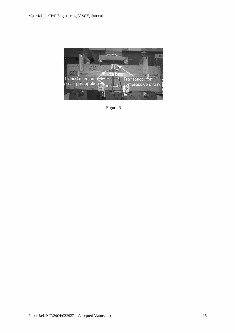
experimental errors (due to spurious support displacements, machine stiffness, and load rate)
and the effect of torsion on the deflection measurements of notched prisms, a yoke was used
(Fig. 6) as specified in the Japanese standard for bending tests (JSCE, 1994). The specimens
were tested in a 100 kN servo-hydraulic machine under displacement control at a constant
rate of 0.2 mm/min. Average mid-span prism deflections were measured on both sides of the
prism using two transducers fixed to the yoke (Fig. 6).
The ABAQUS finite-element package (Hibbitt et al. 2000) is used to perform the inverse
analysis, since it allows the definition of the strain-softening behavior for cracked concrete in as many
stages as needed. The analysis is performed by incremental loading, with integration in each
increment. Since considerable nonlinearity is expected in the response of the analyzed prism
(including the possibility of instability as concrete cracks), the load magnitudes are covered by a
Materials in Civil Engineering (ASCE) Journal
Paper Ref. MT/2004/022927 – Accepted Manuscript 8
single scalar parameter. The modified Riks algorithm of ABAQUS with automatic increments is used,
which uses the “arc length” along the static equilibrium path in the load-displacement space. To take
advantage of symmetry, only half of the prism is modeled and to simulate the notch along the
symmetry axis, nodes within the notch’s height are unrestrained. Initially a mesh size of 25 mm was
used (Tlemat et al. 2005).
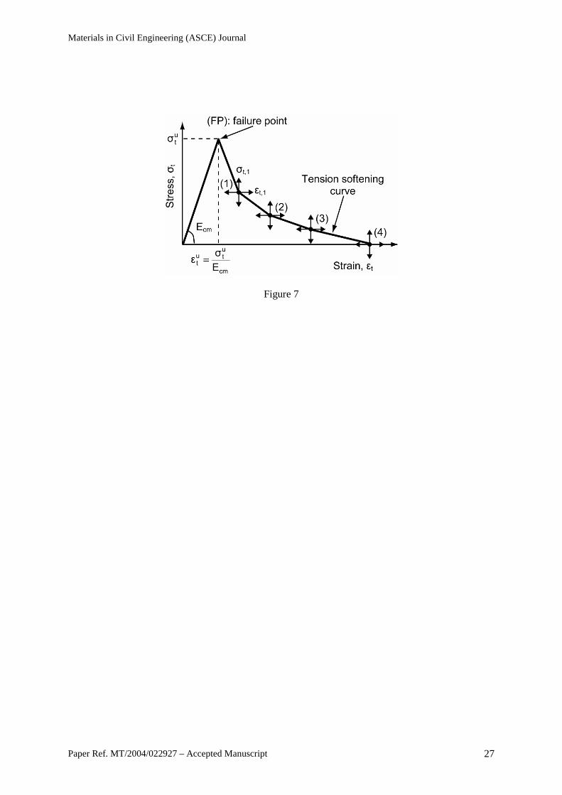
The tension stiffening of concrete is simulated by a multi-linear descending curve, whose
gradient is varied as illustrated in Fig. 7. Up to point (FP), the concrete is considered to be uncracked
having the same elastic modulus as the initial modulus in compression (Ecm). This point is established
iteratively, by using the LOP as the starting point. After this point, subsequent points (1), (2), (3), and
(4) are obtained by iteration, until the experimental load-deflection curve is followed accurately. It is
noted that the tensile strain at points (1), (2,), (3) and (4) is constant at 2‰, 10‰, 25‰ and 40‰,
respectively (Tlemat et al. 2005).
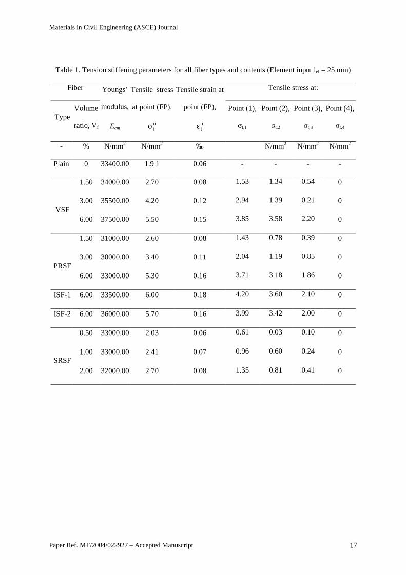
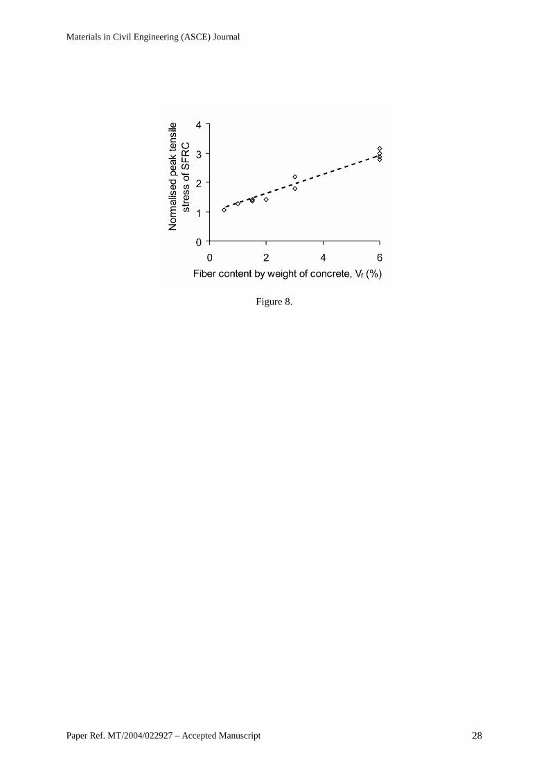
Table 1 shows the optimized tension stiffening stress-parameters obtained by the inverse
analysis for each fiber type and content (Tlemat et al. 2005). The results indicate that the peak tensile
stress ( utσ ), obtained at point (FP) is affected by Vf. This relationship is examined further by
normalizing the values of utσ against the peak tensile stress of plain concrete ( u
pt,σ = 1.91 N/mm2).
Fig. 8 shows that there is a direct relationship between the normalized utσ ( u
ntσ ) and Vf, and it can be
estimated by equation 4. It is noted that Vf is defined as a percentage of the weight of concrete.
)V0.32(1σσ fu
pt,ut ⋅+= (N/mm2) (4)
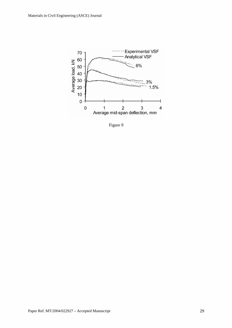
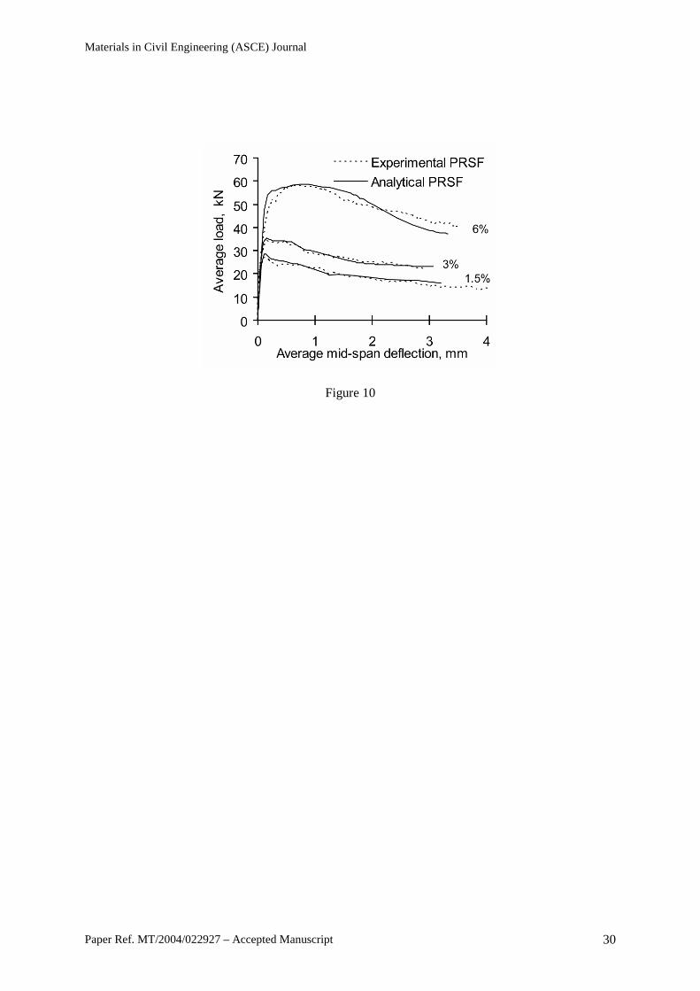
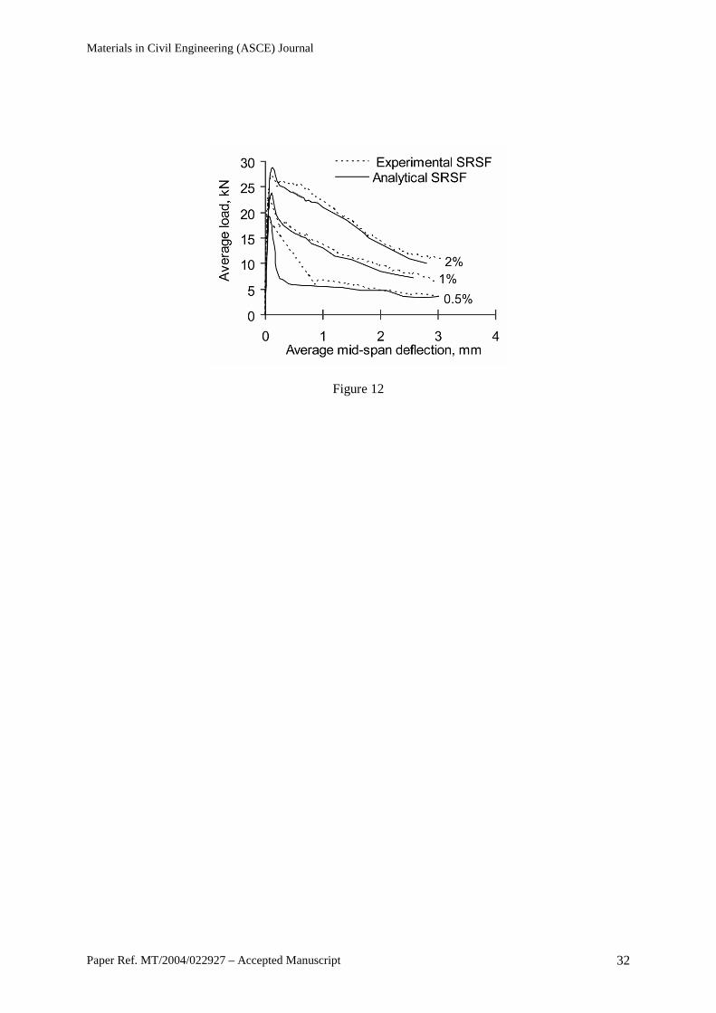
Using the values shown in Table 1, the load-deflection curves, calculated by using ABAQUS,
are in good agreement with the experimental results for all fiber types and Vf (Fig. 9 to 12). It is noted
that the predicted curves are only shown up to a tensile strain of 25‰ (ε3).
Materials in Civil Engineering (ASCE) Journal
Paper Ref. MT/2004/022927 – Accepted Manuscript 9
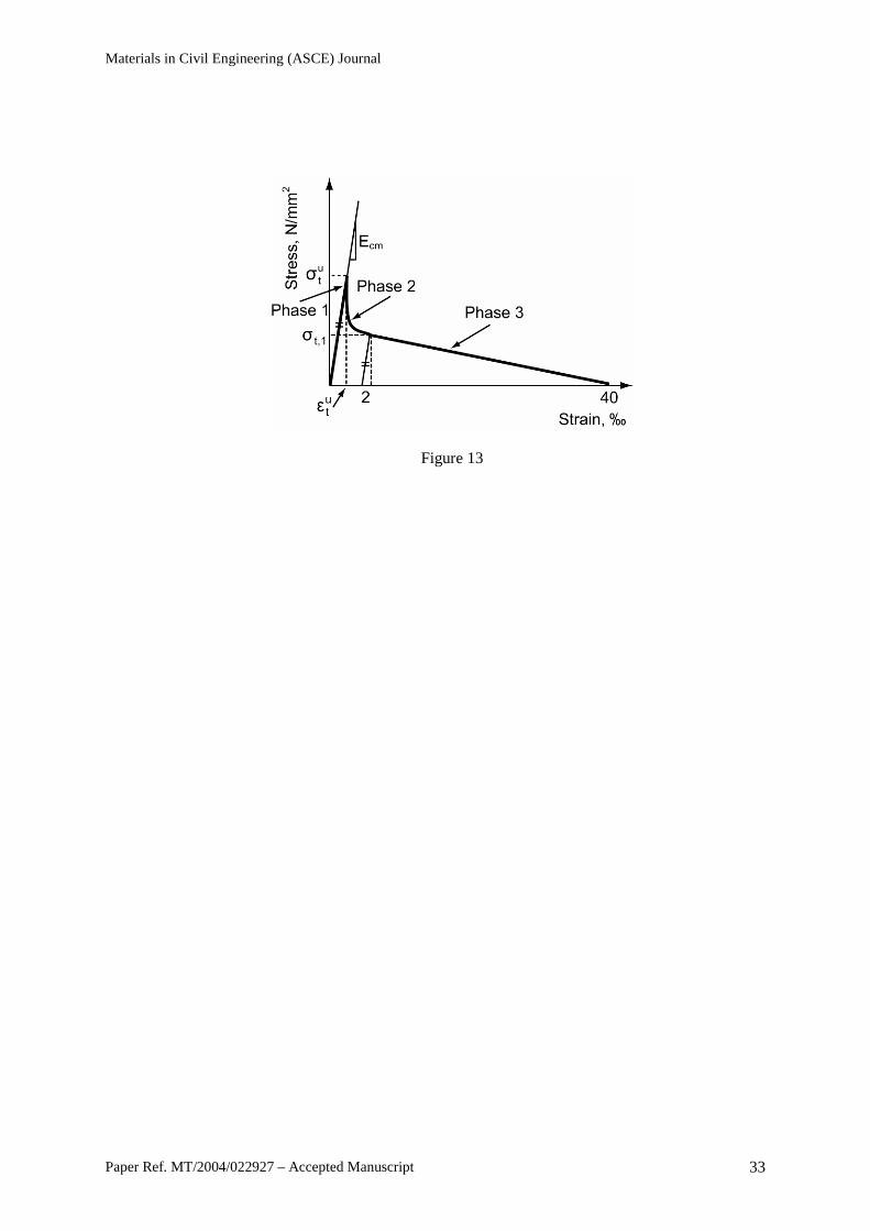
Multi-linear models, such as the one obtained from the back-analysis, require the determination
of many points and rely on extensive experimental results. To simplify the constitutive model, a
model such as the one shown in Fig. 13 needs to be developed, as it represents the behavior of SFRC
in a more realistic manner. However, to simulate the drop in stress in phase 2 (Tlemat et al. 2005), this
model requires extremely accurate displacement-controlled experimental data, which are impossible
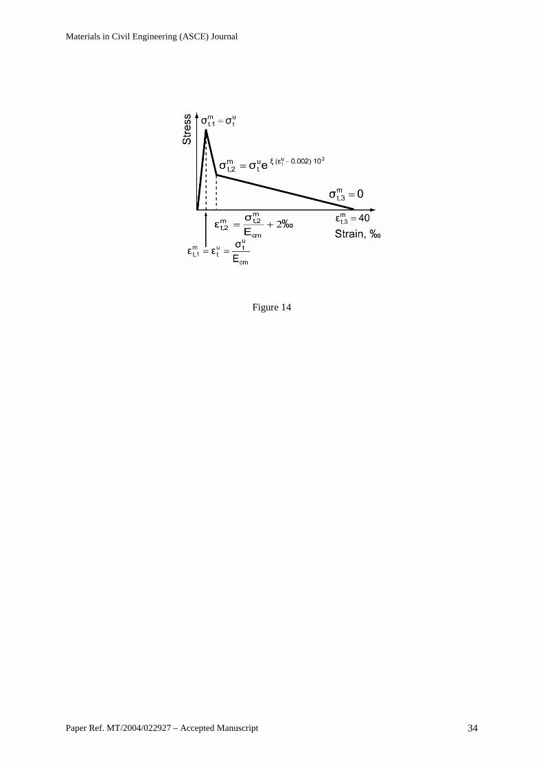
to obtain due to the sudden loss of stiffness in the cracked region. As a compromise, a linear drop is
proposed instead, as shown in Fig. 14. By considering the optimized stress values reported in Table 1,
the stress-drop ratio (φ) is defined as the ratio of the stress just after cracking to the peak stress. By
assuming that the stress decay shown in Fig. 13 is characterized by an exponential relationship, it is
possible to estimate a factor ξ that reflects the influence of fiber type on the tensile softening (equation
5). The following values of φ and ξ are obtained for each fiber type: VSF (φ, ξ = 0.70; 0.20), PRSF
(φ, ξ = 0.60; 0.28), ISF-1 (φ, ξ = 0.73; 0.17), ISF-2 (φ, ξ = 0.71; 0.19) and SRSF (φ, ξ = 0.38; 0.51).
3ut
10 0.002)(ε ξ
10 0.002)(εlne
3ut
−=⇒= − φξφ (5)
Model validation
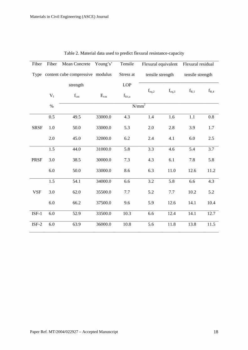
The modified tensile σ-ε model, proposed in the previous section, is used to predict the flexural
(unfactored) resistance-capacity of tested concrete prisms. For comparison purposes, the two tensile
σ-ε models obtained by using the RILEM recommendations are also used to predict the resistance-
capacity of the prisms. The prisms, tested in four-point bending (Fig. 6, Tlemat 2004), were 150 mm
deep, 150 mm wide, 550 mm long and were reinforced with RSF obtained from both the shredding of
tires and pyrolysis of tires, as well as industrially produced fibers and fibers obtained by cutting tire
cord (Fig. 5). It is noted that three specimens were tested for each fiber type. The material properties
of each prism are shown in Table 2 and the calculation procedure is outlined in Appendix A. The
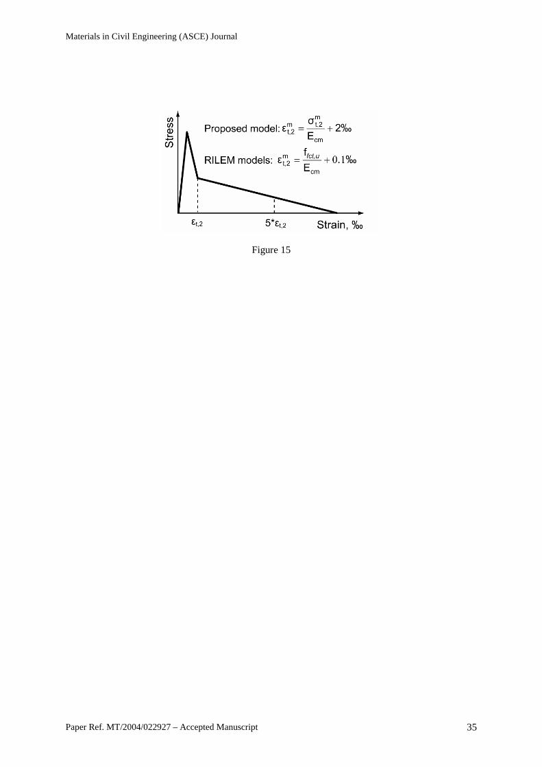
resistance-capacity of each prism is calculated by using as limit-state the ultimate tensile strain (εult)
adopted by each model (10‰ for feq, 25‰ for fR and 40‰ for the proposed model), as well as the
tensile strains ε2 and 5ε2 (shown in Fig. 15).
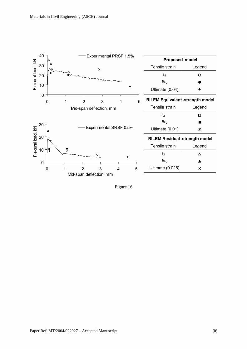
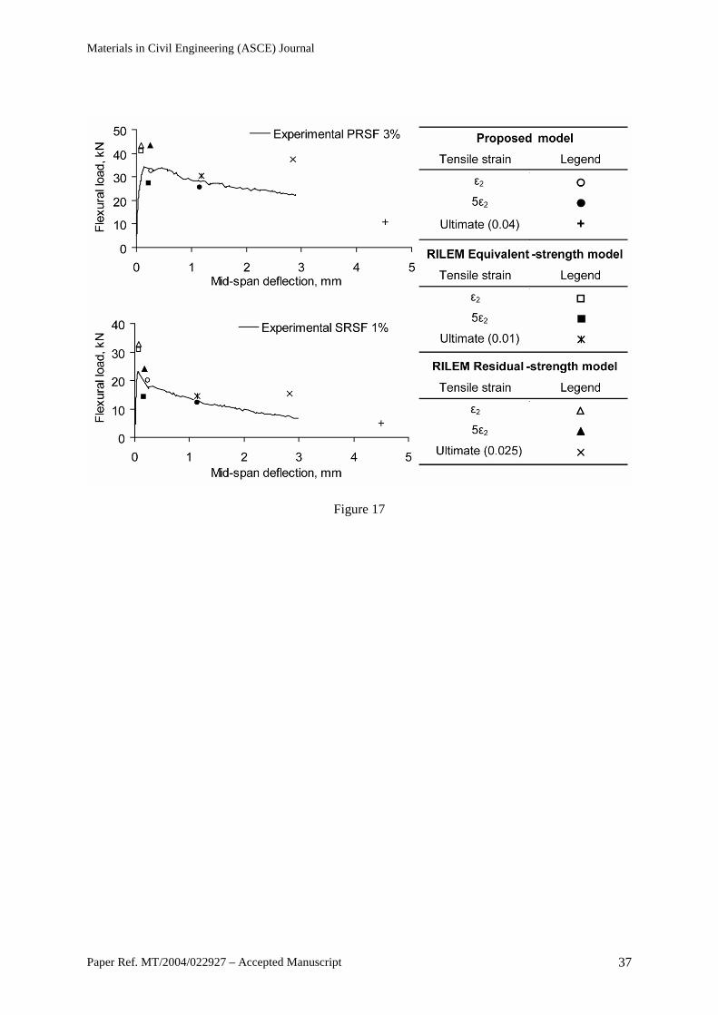
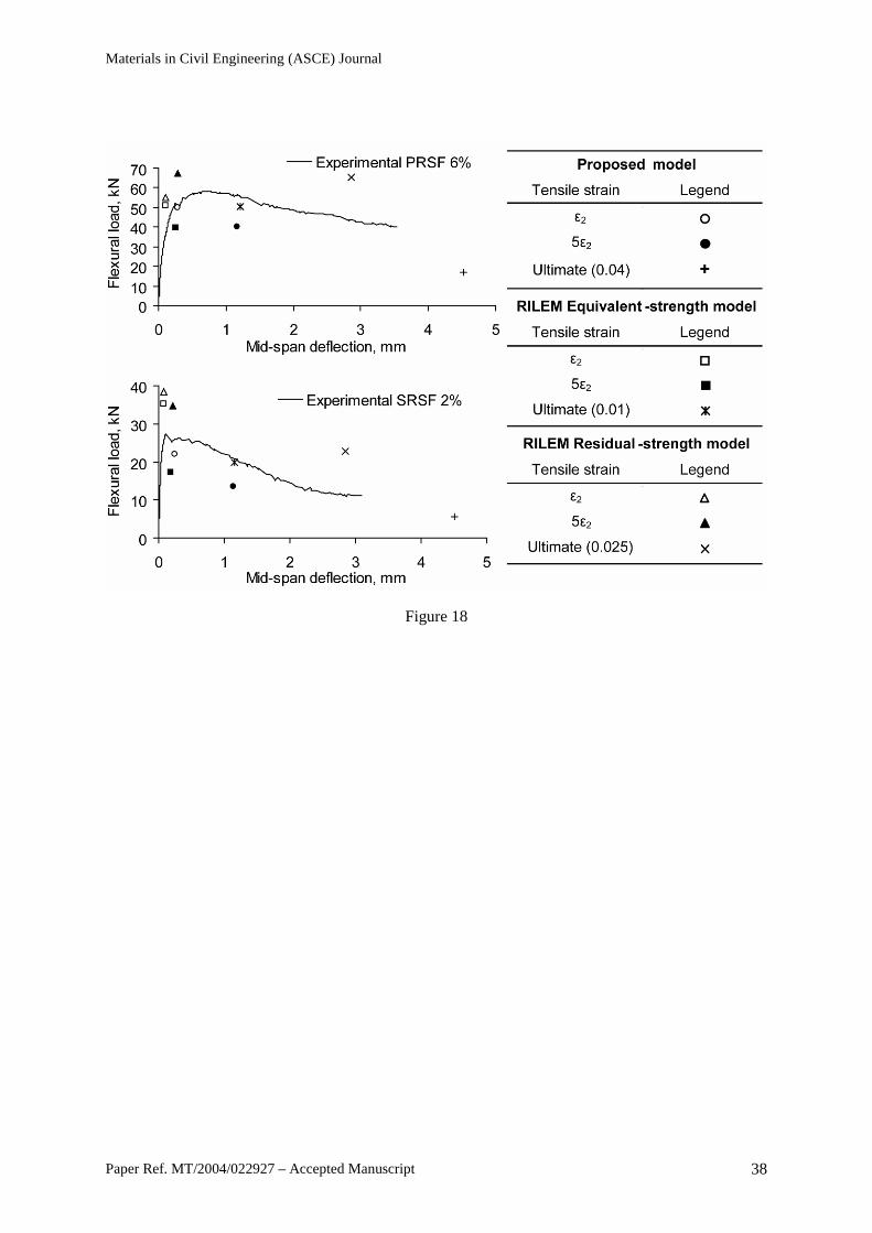
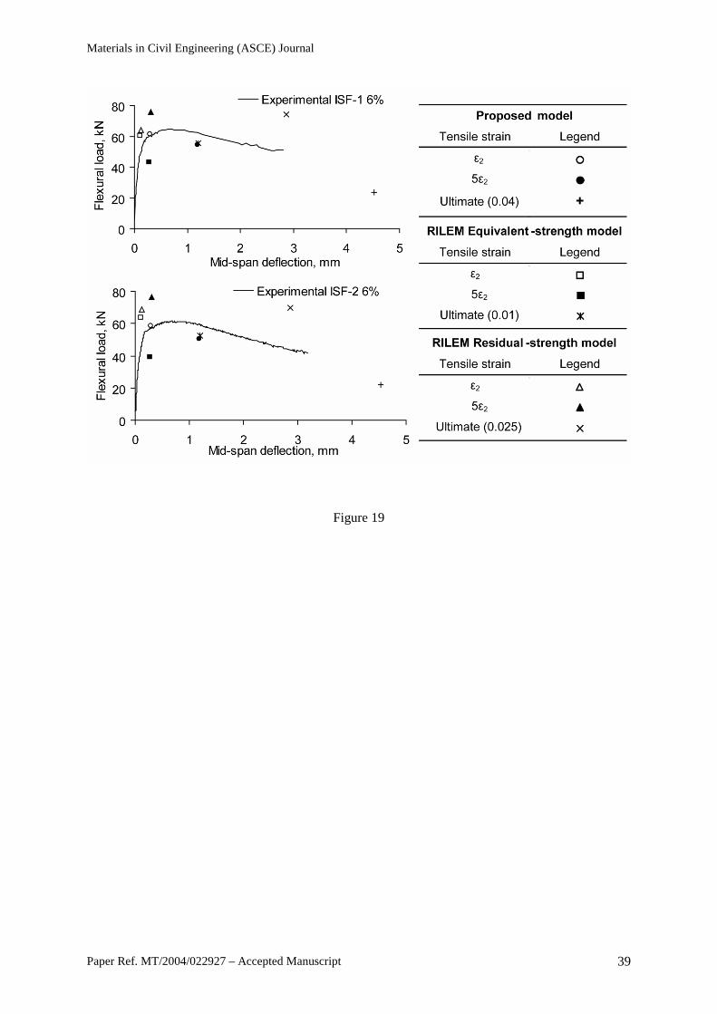
As shown in Fig. 16 to 18 for prisms reinforced with PRSF and SRSF and in Fig. 19 for
prisms reinforced with ISF-1 and ISF-2, the application of the three tensile σ-ε models led to different
Materials in Civil Engineering (ASCE) Journal
Paper Ref. MT/2004/022927 – Accepted Manuscript 10
values for the flexural load-capacity of the prisms. Similar results were also obtained for the prisms
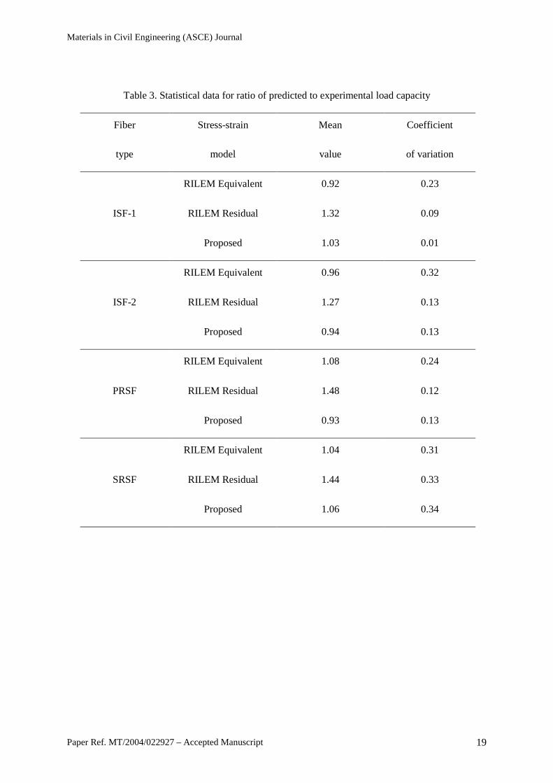
reinforced with VSF (not shown here). Table 3 summarizes (for ISF-1, ISF-2, PRSF and SRSF) the
mean value and coefficient of variation (COV) of the ratio of the load-capacity predicted by each
model divided by the experimental load-capacity. These results show that the load-capacity values
predicted by the proposed model are generally more conservative and uniform than the values
predicted by the RILEM models. Although similar mean values are calculated for the proposed and
equivalent-strength model, higher COVs are obtained for the latter model, which also had more
variable results than the residual-strength model. However, the equivalent-strength model is more
conservative than the residual-strength model due to much lower mean values. As expected, the more
random nature of the shredded fiber also led to a higher variability of the results.
Deformation Limits
The RILEM σ-ε models give deformations which satisfy the deformation limit adopted for the
ultimate limit state by the two RILEM guidelines (1.5 mm and 3.5 for the 2000 and 2003 guideline,
respectively). The proposed model adopts a larger value for the tensile strain εult and, hence, leads to
ultimate limit state deformations of 4.5mm and corresponding lower ultimate resisting-capacities.
One of the problems associated with the design of SFRC at ultimate limit state is the selection
of appropriate control parameters for the calculation of the load-capacity and corresponding
deformation. In general, the tensile strain of SFRC is used as the control parameter.
The resistance-capacity, predicted for the tested prisms by using the tensile strain ε2,
corresponds to the maximum load-capacity. This resistance-capacity does not necessarily lead to safe
designs, due to lack of ductility, and hence, the value of ε2 should only be used to check the peak load-
capacity for elastic analysis.
In the case of statically-determinate elements, where failure is due to a single hinge (possibly
due to a single crack), the ultimate load-capacity predicted by using the tensile strain 5ε2 is more
appropriate for design purposes. This load-capacity will be maintained at a displacement ductility of
around 5 and cracking will be limited to around 1mm (according to the proposed σ-ε model).
Materials in Civil Engineering (ASCE) Journal
Paper Ref. MT/2004/022927 – Accepted Manuscript 11
The load-capacities calculated by using the tensile strain εult will enable a larger degree of
ductility and safety. It is proposed that εult is used as the control strain for the design of structural
elements (such as slabs-on-grade) which require high moment redistribution and high deformations.
Conclusions
This study investigates the design philosophy of the RILEM σ-ε guideline for SFRC, in order to
assess its suitability for the design of RSFRC. It is shown that the guideline overestimates the flexural
resistance-capacity of SFRC. This is attributed to inaccuracies in the determination of the tensile σ-ε
model.
An inverse finite-element analysis method was proposed for deriving the tensile σ-ε
characteristics of SFRC. This is achieved by optimizing the tension stiffening model until the
analytical load-deflection curve fits closely the curve obtained from four-point bending tests. Based
on these results, a simplified model is proposed that can be used for design purposes. A key feature of
the proposed model is that, for a specific fiber content, the peak stress value can be determined by
using only the fiber ratio and it is independent of the fiber type. However, the drop of stress following
cracking is a function of the fiber type.
The proposed stress-strain model and those recommended by RILEM are used to predict the
flexural resistance-capacity of prisms reinforced with conventional and recycled steel fibers. The
proposed model leads to conservative predictions, while the predictions of the RILEM models are
often unconservative. The RILEM models, in particular the equivalent-strength model, lead to more
variable results than the proposed model.
Acknowledgements
The authors wish to acknowledge the Marie-Curie EU Community program “Improving Human
Research Potential and the Socio-economic Knowledge Base” under contract number HPMF-CT-
2002-01825, and UK Government’s Department of Trade and Industry for the partners in innovation
project “Demonstrating steel fibers from waste tires as reinforcement in concrete” (contract: CI
39/3/684, cc2227).
Materials in Civil Engineering (ASCE) Journal
Paper Ref. MT/2004/022927 – Accepted Manuscript 12
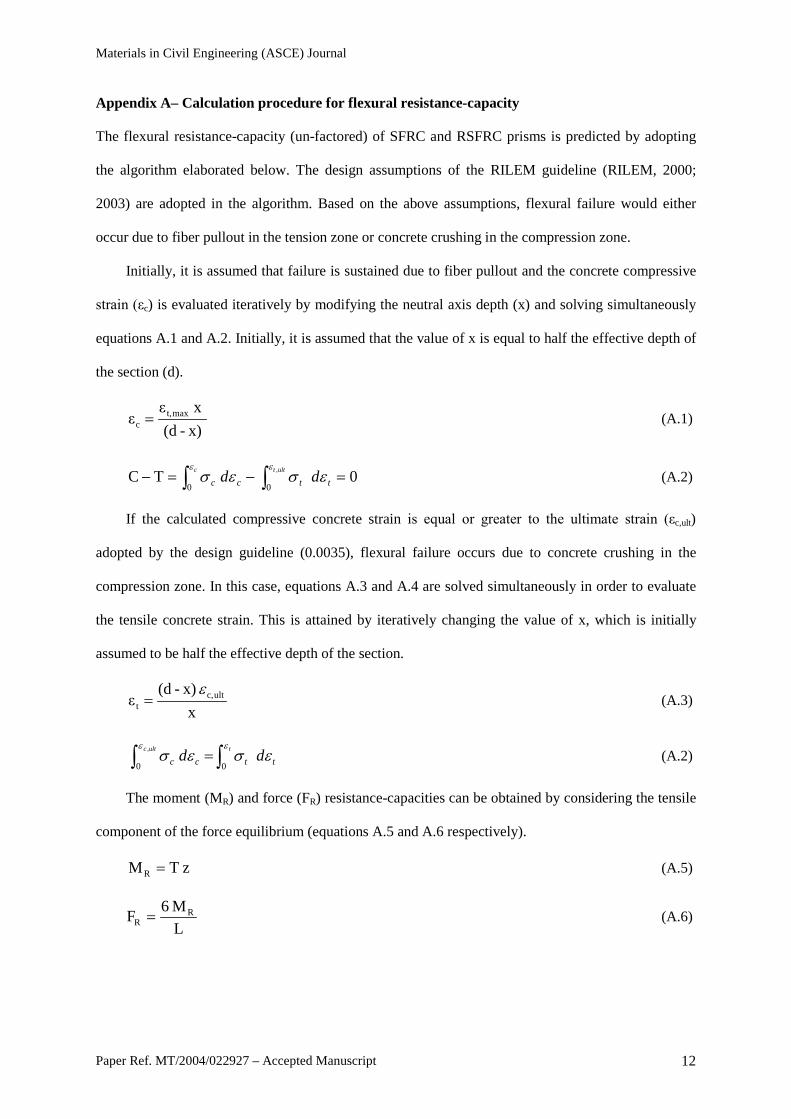
Appendix A– Calculation procedure for flexural resistance-capacity
The flexural resistance-capacity (un-factored) of SFRC and RSFRC prisms is predicted by adopting
the algorithm elaborated below. The design assumptions of the RILEM guideline (RILEM, 2000;
2003) are adopted in the algorithm. Based on the above assumptions, flexural failure would either
occur due to fiber pullout in the tension zone or concrete crushing in the compression zone.
Initially, it is assumed that failure is sustained due to fiber pullout and the concrete compressive
strain (εc) is evaluated iteratively by modifying the neutral axis depth (x) and solving simultaneously
equations A.1 and A.2. Initially, it is assumed that the value of x is equal to half the effective depth of
the section (d).
x)-(d x ε
ε maxt,c = (A.1)
0 TC ,
0
0 =−=− ∫∫
ulttc
ttcc ddεε
εσεσ (A.2)
If the calculated compressive concrete strain is equal or greater to the ultimate strain (εc,ult)
adopted by the design guideline (0.0035), flexural failure occurs due to concrete crushing in the
compression zone. In this case, equations A.3 and A.4 are solved simultaneously in order to evaluate
the tensile concrete strain. This is attained by iteratively changing the value of x, which is initially
assumed to be half the effective depth of the section.
x x)- (d
ε ultc,t
ε= (A.3)
∫∫ = tultc
ttcc ddεε
εσεσ
0
0 , (A.2)
The moment (MR) and force (FR) resistance-capacities can be obtained by considering the tensile
component of the force equilibrium (equations A.5 and A.6 respectively).
z TMR = (A.5)
LM 6F R
R = (A.6)

Materials in Civil Engineering (ASCE) Journal
Paper Ref. MT/2004/022927 – Accepted Manuscript 13
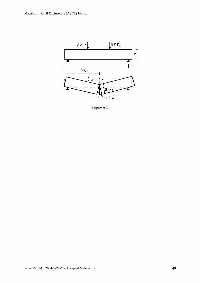
The total deflection (δ) sustained by the prism is calculated according to the RILEM guideline
by considering the elastic deflection (δel) and the deflection sustained after cracking (δw), (equation
A.7). The value of δw is calculated by assuming that the prism behaves as a rigid body (Fig. A.1).
4L
I E 1296L F 23
x)-4(hL x)-(h
I E 1296L F 23
x)-4(hL w
I E 1296L F 23 t
cm
3Rt
cm
3R
cm
3R εεδδδ +=+=+=+= wel (A.7)
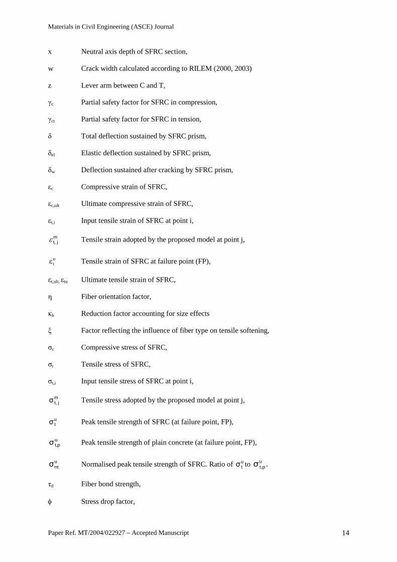
Notation
C Compressive force of steel fiber reinforced concrete (SFRC),
Ecm, Ec0 Young’s modulus of plain concrete,
Esteel Young’s modulus of steel,
F Applied load,
Fi Experimental bending load at location i,
FR Force resistance-capacity of SFRC,
I Moment of Inertia of SFRC section,
L Span of SFRC prism
L/d Fiber aspect ratio,
MR Moment resistance-capacity of SFRC section,
R Coefficient of determination (R-squared value of a trend-line),
T Tensile force in SFRC,
Vf Fiber content by weight of concrete, expressed as a percentage of the concrete weight,
fck Characteristic concrete cylinder compressive strength,
fcm Mean concrete cylinder compressive strength,
feq Equivalent flexural tensile strength of SFRC,
fft Axial tensile strength of SFRC,
fR Residual flexural tensile strength of SFRC,
ftu Ultimate tensile strength of SFRC,
b Width of SFRC section,
d Effective depth of SFRC section,
h Overall depth of SFRC section,
Materials in Civil Engineering (ASCE) Journal
Paper Ref. MT/2004/022927 – Accepted Manuscript 14
x Neutral axis depth of SFRC section,
w Crack width calculated according to RILEM (2000, 2003)
z Lever arm between C and T,
γc Partial safety factor for SFRC in compression,
γct Partial safety factor for SFRC in tension,
δ Total deflection sustained by SFRC prism,
δel Elastic deflection sustained by SFRC prism,
δw Deflection sustained after cracking by SFRC prism,
εc Compressive strain of SFRC,
εc,ult Ultimate compressive strain of SFRC,
εt,i Input tensile strain of SFRC at point i,
mj t,ε Tensile strain adopted by the proposed model at point j,
utε Tensile strain of SFRC at failure point (FP),
εt,ult, εtu Ultimate tensile strain of SFRC,
η Fiber orientation factor,
κh Reduction factor accounting for size effects
ξ Factor reflecting the influence of fiber type on tensile softening,
σc Compressive stress of SFRC,
σt Tensile stress of SFRC,
σt,i Input tensile stress of SFRC at point i,
mj t,σ Tensile stress adopted by the proposed model at point j,
utσ Peak tensile strength of SFRC (at failure point, FP),
upt,σ Peak tensile strength of plain concrete (at failure point, FP),
untσ Normalised peak tensile strength of SFRC. Ratio of u
tσ to .σupt,
τd Fiber bond strength,
φ Stress drop factor,
Materials in Civil Engineering (ASCE) Journal
Paper Ref. MT/2004/022927 – Accepted Manuscript 15
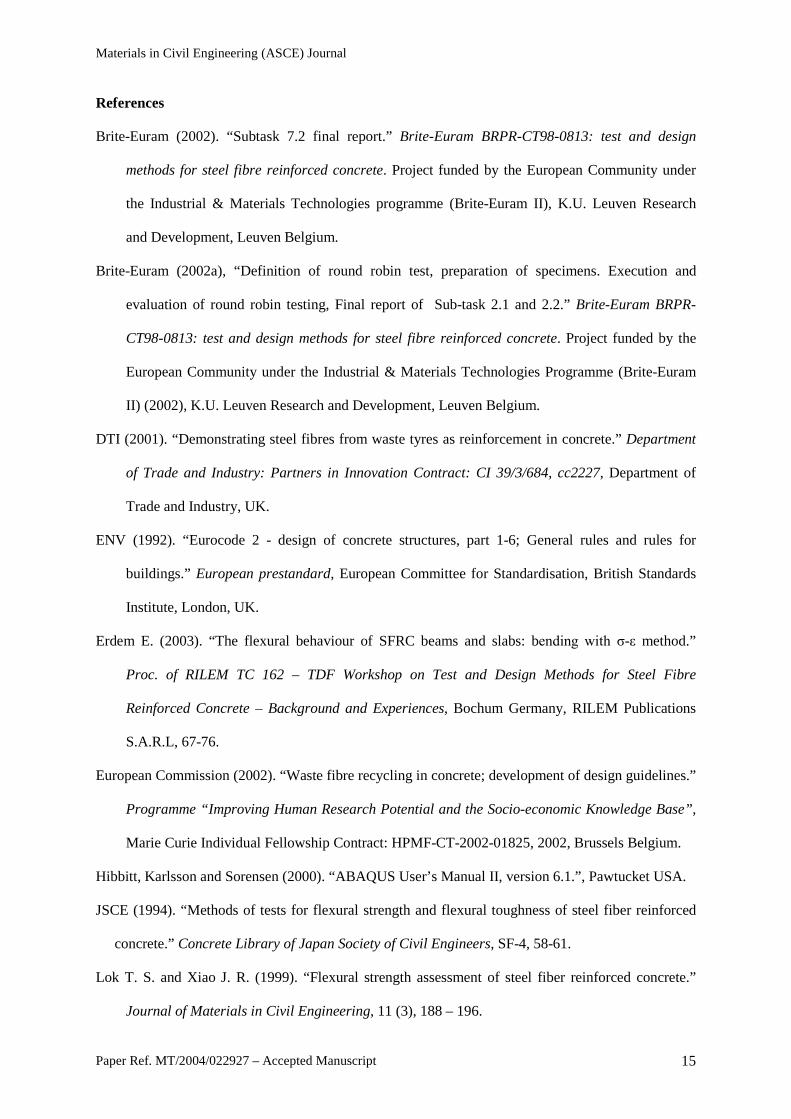
References
Brite-Euram (2002). “Subtask 7.2 final report.” Brite-Euram BRPR-CT98-0813: test and design
methods for steel fibre reinforced concrete. Project funded by the European Community under
the Industrial & Materials Technologies programme (Brite-Euram II), K.U. Leuven Research
and Development, Leuven Belgium.
Brite-Euram (2002a), “Definition of round robin test, preparation of specimens. Execution and
evaluation of round robin testing, Final report of Sub-task 2.1 and 2.2.” Brite-Euram BRPR-
CT98-0813: test and design methods for steel fibre reinforced concrete. Project funded by the
European Community under the Industrial & Materials Technologies Programme (Brite-Euram
II) (2002), K.U. Leuven Research and Development, Leuven Belgium.
DTI (2001). “Demonstrating steel fibres from waste tyres as reinforcement in concrete.” Department
of Trade and Industry: Partners in Innovation Contract: CI 39/3/684, cc2227, Department of
Trade and Industry, UK.
ENV (1992). “Eurocode 2 - design of concrete structures, part 1-6; General rules and rules for
buildings.” European prestandard, European Committee for Standardisation, British Standards
Institute, London, UK.
Erdem E. (2003). “The flexural behaviour of SFRC beams and slabs: bending with σ-ε method.”
Proc. of RILEM TC 162 – TDF Workshop on Test and Design Methods for Steel Fibre
Reinforced Concrete – Background and Experiences, Bochum Germany, RILEM Publications
S.A.R.L, 67-76.
European Commission (2002). “Waste fibre recycling in concrete; development of design guidelines.”
Programme “Improving Human Research Potential and the Socio-economic Knowledge Base”,
Marie Curie Individual Fellowship Contract: HPMF-CT-2002-01825, 2002, Brussels Belgium.
Hibbitt, Karlsson and Sorensen (2000). “ABAQUS User’s Manual II, version 6.1.”, Pawtucket USA.
JSCE (1994). “Methods of tests for flexural strength and flexural toughness of steel fiber reinforced
concrete.” Concrete Library of Japan Society of Civil Engineers, SF-4, 58-61.
Lok T. S. and Xiao J. R. (1999). “Flexural strength assessment of steel fiber reinforced concrete.”
Journal of Materials in Civil Engineering, 11 (3), 188 – 196.
Materials in Civil Engineering (ASCE) Journal
Paper Ref. MT/2004/022927 – Accepted Manuscript 16
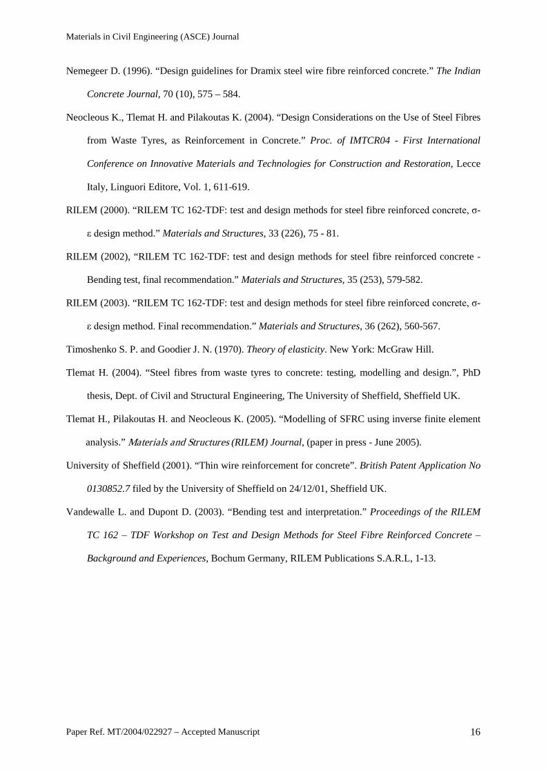
Nemegeer D. (1996). “Design guidelines for Dramix steel wire fibre reinforced concrete.” The Indian
Concrete Journal, 70 (10), 575 – 584.
Neocleous K., Tlemat H. and Pilakoutas K. (2004). “Design Considerations on the Use of Steel Fibres
from Waste Tyres, as Reinforcement in Concrete.” Proc. of IMTCR04 - First International
Conference on Innovative Materials and Technologies for Construction and Restoration, Lecce
Italy, Linguori Editore, Vol. 1, 611-619.
RILEM (2000). “RILEM TC 162-TDF: test and design methods for steel fibre reinforced concrete, σ-
ε design method.” Materials and Structures, 33 (226), 75 - 81.
RILEM (2002), “RILEM TC 162-TDF: test and design methods for steel fibre reinforced concrete -
Bending test, final recommendation.” Materials and Structures, 35 (253), 579-582.
RILEM (2003). “RILEM TC 162-TDF: test and design methods for steel fibre reinforced concrete, σ-
ε design method. Final recommendation.” Materials and Structures, 36 (262), 560-567.
Timoshenko S. P. and Goodier J. N. (1970). Theory of elasticity. New York: McGraw Hill.
Tlemat H. (2004). “Steel fibres from waste tyres to concrete: testing, modelling and design.”, PhD
thesis, Dept. of Civil and Structural Engineering, The University of Sheffield, Sheffield UK.
Tlemat H., Pilakoutas H. and Neocleous K. (2005). “Modelling of SFRC using inverse finite element
analysis.” Materials and Structures (RILEM) Journal, (paper in press - June 2005).
University of Sheffield (2001). “Thin wire reinforcement for concrete”. British Patent Application No
0130852.7 filed by the University of Sheffield on 24/12/01, Sheffield UK.
Vandewalle L. and Dupont D. (2003). “Bending test and interpretation.” Proceedings of the RILEM
TC 162 – TDF Workshop on Test and Design Methods for Steel Fibre Reinforced Concrete –
Background and Experiences, Bochum Germany, RILEM Publications S.A.R.L, 1-13.
Materials in Civil Engineering (ASCE) Journal
Paper Ref. MT/2004/022927 – Accepted Manuscript 17
Table 1. Tension stiffening parameters for all fiber types and contents (Element input lel = 25 mm)
Fiber Youngs’
modulus,
Ecm
Tensile stress
at point (FP),
utσ
Tensile strain at
point (FP),
utε
Tensile stress at:
Type Volume
ratio, Vf
Point (1),
σt,1
Point (2),
σt,2
Point (3),
σt,3
Point (4),
σt,4
- % N/mm2 N/mm2 ‰ N/mm2 N/mm2 N/mm2
Plain 0 33400.00 1.9 1 0.06 - - - -
VSF
1.50 34000.00 2.70 0.08 1.53 1.34 0.54 0
3.00 35500.00 4.20 0.12 2.94 1.39 0.21 0
6.00 37500.00 5.50 0.15 3.85 3.58 2.20 0
PRSF
1.50 31000.00 2.60 0.08 1.43 0.78 0.39 0
3.00 30000.00 3.40 0.11 2.04 1.19 0.85 0
6.00 33000.00 5.30 0.16 3.71 3.18 1.86 0
ISF-1 6.00 33500.00 6.00 0.18 4.20 3.60 2.10 0
ISF-2 6.00 36000.00 5.70 0.16 3.99 3.42 2.00 0
SRSF
0.50 33000.00 2.03 0.06 0.61 0.03 0.10 0
1.00 33000.00 2.41 0.07 0.96 0.60 0.24 0
2.00 32000.00 2.70 0.08 1.35 0.81 0.41 0
Materials in Civil Engineering (ASCE) Journal
Paper Ref. MT/2004/022927 – Accepted Manuscript 18
Table 2. Material data used to predict flexural resistance-capacity
Fiber
Type
Fiber
content
Vf
Mean Concrete
cube compressive
strength
fcm
Young’s’
modulus
Ecm
Tensile
Stress at
LOP
ffct,u
Flexural equivalent
tensile strength
Flexural residual
tensile strength
feq,2 feq,3 fR,1 fR,4
% N/mm2
SRSF
0.5 49.5 33000.0 4.3 1.4 1.6 1.1 0.8
1.0 50.0 33000.0 5.3 2.0 2.8 3.9 1.7
2.0 45.0 32000.0 6.2 2.4 4.1 6.0 2.5
PRSF
1.5 44.0 31000.0 5.8 3.3 4.6 5.4 3.7
3.0 38.5 30000.0 7.3 4.3 6.1 7.8 5.8
6.0 50.0 33000.0 8.6 6.3 11.0 12.6 11.2
VSF
1.5 54.1 34000.0 6.6 3.2 5.8 6.6 4.3
3.0 62.0 35500.0 7.7 5.2 7.7 10.2 5.2
6.0 66.2 37500.0 9.6 5.9 12.6 14.1 10.4
ISF-1 6.0 52.9 33500.0 10.3 6.6 12.4 14.1 12.7
ISF-2 6.0 63.9 36000.0 10.8 5.6 11.8 13.8 11.5
Materials in Civil Engineering (ASCE) Journal
Paper Ref. MT/2004/022927 – Accepted Manuscript 19
Table 3. Statistical data for ratio of predicted to experimental load capacity
Fiber
type
Stress-strain
model
Mean
value
Coefficient
of variation
ISF-1
RILEM Equivalent 0.92 0.23
RILEM Residual 1.32 0.09
Proposed 1.03 0.01
ISF-2
RILEM Equivalent 0.96 0.32
RILEM Residual 1.27 0.13
Proposed 0.94 0.13
PRSF
RILEM Equivalent 1.08 0.24
RILEM Residual 1.48 0.12
Proposed 0.93 0.13
SRSF
RILEM Equivalent 1.04 0.31
RILEM Residual 1.44 0.33
Proposed 1.06 0.34
Materials in Civil Engineering (ASCE) Journal
Paper Ref. MT/2004/022927 – Accepted Manuscript 20
Figure Captions:
Figure 1. RILEM stress-strain model adopted for SFRC (after RILEM 2000, “with permission”)
Figure 2. Tensile stress-strain model proposed by Lok and Xiao (1999)
Figure 3. Load spreading effect for three and four-point loading arrangements
Figure 4. Correlation between equivalent-strengths and residual-strengths
Figure 5. Types of fiber used to reinforce the concrete prisms
Figure 6. Four-point bending test arrangement used for SFRC and RSFRC prisms
Figure 7. Tension stiffening model adopted in FE analysis
Figure 8. Relationship between peak tensile stress of SFRC and fiber content
Figure 9. Analytical and experimental load-deflection curves for prisms reinforced with VSF
Figure 10. Analytical and experimental load-deflection curves for prisms reinforced with PRSF
Figure 11. Analytical and experimental load-deflection curves for prisms reinforced with ISF-1 and
ISF-2
Figure 12. Analytical and experimental load-deflection curves for prisms reinforced with SRSF
Figure 13. Idealized uniaxial tensile stress-strain model for SFRC
Figure 14. Proposed uniaxial tensile stress-train model
Figure 15. Tensile strains used to predict the flexural capacity of the prisms
Figure 16. Comparison of predicted and experimental resistance-capacities (prisms reinforced with
1.5% PRSF and 0.5% SRSF)
Figure 17. Comparison of predicted and experimental resistance-capacities (prisms reinforced with
3% PRSF and 1% SRSF)
Figure 18. Comparison of predicted and experimental resistance-capacities (prisms reinforced with
6% PRSF and 2% SRSF)
Figure 19. Comparison of predicted and experimental resistance-capacities (prisms reinforced with
6% ISF-1 and 6% ISF-2)
Figure A.1 Relationship between deflection and crack width
Materials in Civil Engineering (ASCE) Journal
Paper Ref. MT/2004/022927 – Accepted Manuscript 21
Figure 1
Materials in Civil Engineering (ASCE) Journal
Paper Ref. MT/2004/022927 – Accepted Manuscript 22
Figure 2
Materials in Civil Engineering (ASCE) Journal
Paper Ref. MT/2004/022927 – Accepted Manuscript 23
Figure 3
Materials in Civil Engineering (ASCE) Journal
Paper Ref. MT/2004/022927 – Accepted Manuscript 24
Figure 4

Materials in Civil Engineering (ASCE) Journal
Paper Ref. MT/2004/022927 – Accepted Manuscript 25
Figure 5
Materials in Civil Engineering (ASCE) Journal
Paper Ref. MT/2004/022927 – Accepted Manuscript 26
Figure 6
Materials in Civil Engineering (ASCE) Journal
Paper Ref. MT/2004/022927 – Accepted Manuscript 27
Figure 7
Materials in Civil Engineering (ASCE) Journal
Paper Ref. MT/2004/022927 – Accepted Manuscript 28
Figure 8.
Materials in Civil Engineering (ASCE) Journal
Paper Ref. MT/2004/022927 – Accepted Manuscript 29
Figure 9
Materials in Civil Engineering (ASCE) Journal
Paper Ref. MT/2004/022927 – Accepted Manuscript 30
Figure 10

Materials in Civil Engineering (ASCE) Journal
Paper Ref. MT/2004/022927 – Accepted Manuscript 31
Figure 11
Materials in Civil Engineering (ASCE) Journal
Paper Ref. MT/2004/022927 – Accepted Manuscript 32
Figure 12
Materials in Civil Engineering (ASCE) Journal
Paper Ref. MT/2004/022927 – Accepted Manuscript 33
Figure 13
Materials in Civil Engineering (ASCE) Journal
Paper Ref. MT/2004/022927 – Accepted Manuscript 34
Figure 14
Materials in Civil Engineering (ASCE) Journal
Paper Ref. MT/2004/022927 – Accepted Manuscript 35
Figure 15
Materials in Civil Engineering (ASCE) Journal
Paper Ref. MT/2004/022927 – Accepted Manuscript 36
Figure 16
Materials in Civil Engineering (ASCE) Journal
Paper Ref. MT/2004/022927 – Accepted Manuscript 37
Figure 17
Materials in Civil Engineering (ASCE) Journal
Paper Ref. MT/2004/022927 – Accepted Manuscript 38
Figure 18
Materials in Civil Engineering (ASCE) Journal
Paper Ref. MT/2004/022927 – Accepted Manuscript 39
Figure 19
Materials in Civil Engineering (ASCE) Journal
Paper Ref. MT/2004/022927 – Accepted Manuscript 40
Figure A.1